US8130495B2 - Audio amplifier in compact case with peak voltage and current limiting circuit and thermal cooling tunnel - Google Patents
Audio amplifier in compact case with peak voltage and current limiting circuit and thermal cooling tunnelDownload PDFInfo
- Publication number
- US8130495B2 US8130495B2US12/570,910US57091009AUS8130495B2US 8130495 B2US8130495 B2US 8130495B2US 57091009 AUS57091009 AUS 57091009AUS 8130495 B2US8130495 B2US 8130495B2
- Authority
- US
- United States
- Prior art keywords
- cooling tunnel
- audio
- sound system
- audio amplifier
- compact case
- Prior art date
- Legal status (The legal status is an assumption and is not a legal conclusion. Google has not performed a legal analysis and makes no representation as to the accuracy of the status listed.)
- Expired - Fee Related, expires
Links
Images


Classifications
- G—PHYSICS
- G10—MUSICAL INSTRUMENTS; ACOUSTICS
- G10H—ELECTROPHONIC MUSICAL INSTRUMENTS; INSTRUMENTS IN WHICH THE TONES ARE GENERATED BY ELECTROMECHANICAL MEANS OR ELECTRONIC GENERATORS, OR IN WHICH THE TONES ARE SYNTHESISED FROM A DATA STORE
- G10H1/00—Details of electrophonic musical instruments
- G10H1/32—Constructional details
- G—PHYSICS
- G10—MUSICAL INSTRUMENTS; ACOUSTICS
- G10H—ELECTROPHONIC MUSICAL INSTRUMENTS; INSTRUMENTS IN WHICH THE TONES ARE GENERATED BY ELECTROMECHANICAL MEANS OR ELECTRONIC GENERATORS, OR IN WHICH THE TONES ARE SYNTHESISED FROM A DATA STORE
- G10H3/00—Instruments in which the tones are generated by electromechanical means
- G10H3/12—Instruments in which the tones are generated by electromechanical means using mechanical resonant generators, e.g. strings or percussive instruments, the tones of which are picked up by electromechanical transducers, the electrical signals being further manipulated or amplified and subsequently converted to sound by a loudspeaker or equivalent instrument
- G10H3/14—Instruments in which the tones are generated by electromechanical means using mechanical resonant generators, e.g. strings or percussive instruments, the tones of which are picked up by electromechanical transducers, the electrical signals being further manipulated or amplified and subsequently converted to sound by a loudspeaker or equivalent instrument using mechanically actuated vibrators with pick-up means
- G10H3/18—Instruments in which the tones are generated by electromechanical means using mechanical resonant generators, e.g. strings or percussive instruments, the tones of which are picked up by electromechanical transducers, the electrical signals being further manipulated or amplified and subsequently converted to sound by a loudspeaker or equivalent instrument using mechanically actuated vibrators with pick-up means using a string, e.g. electric guitar
- G10H3/186—Means for processing the signal picked up from the strings
- H—ELECTRICITY
- H03—ELECTRONIC CIRCUITRY
- H03F—AMPLIFIERS
- H03F3/00—Amplifiers with only discharge tubes or only semiconductor devices as amplifying elements
- H03F3/20—Power amplifiers, e.g. Class B amplifiers, Class C amplifiers
- H03F3/21—Power amplifiers, e.g. Class B amplifiers, Class C amplifiers with semiconductor devices only
- H03F3/217—Class D power amplifiers; Switching amplifiers
- G—PHYSICS
- G10—MUSICAL INSTRUMENTS; ACOUSTICS
- G10H—ELECTROPHONIC MUSICAL INSTRUMENTS; INSTRUMENTS IN WHICH THE TONES ARE GENERATED BY ELECTROMECHANICAL MEANS OR ELECTRONIC GENERATORS, OR IN WHICH THE TONES ARE SYNTHESISED FROM A DATA STORE
- G10H2230/00—General physical, ergonomic or hardware implementation of electrophonic musical tools or instruments, e.g. shape or architecture
- G10H2230/025—Computing or signal processing architecture features
- G10H2230/035—Power management, i.e. specific power supply solutions for electrophonic musical instruments, e.g. auto power shut-off, energy saving designs, power conditioning, connector design, avoiding inconvenient wiring
Definitions
- the present inventionrelates in general to audio sound systems and, more particularly, to an audio amplifier in a compact case with peak voltage and current limiting circuit and thermal cooling tunnel with fan for heat dissipation.
- Audio amplifiers and speakers for entertainment systemscan take a variety of forms.
- musical instrumentsgenerate electrical audio signals representative of sounds produced by the instrument.
- Electric guitars and electric bass guitarsare well-known musical instruments. The artist plays the guitar and generates electric signals representative of the intended notes and chords.
- the audio signalsmay be generated from vocals through a microphone.
- the electrical signalsare routed through one or more audio amplifiers for pre-amplification, power amplification, filtering, and other signal processing to enhance the tonal quality and properties of the signal.
- the processed signalsthen drive one or more speaker systems to reproduce the original sound from the musical instrument for the audience.
- FIG. 1illustrates a conventional musical instrument 10 , such as an electric bass guitar, providing electrical signals to audio amplifier 12 .
- audio amplifier 12can be implemented as ICE Power 250ASX2 audio power amplifier.
- Other signal processing units 14such as pre-amplifier or effects loop, can be placed between musical instrument 10 and audio amplifier circuit 12 .
- Audio amplifier 12has separate outputs to drive one or two speaker systems 16 and 18 , such as passive or active speakers, subwoofers, wireless speakers, multimedia audio, and distributed audio. Audio amplifier 12 is typically housed in a compact, small profile case having dimensions of 6.4 ⁇ 25.4 ⁇ 26.7 centimeters (cm) and weight of about 1.7 kilograms.
- Audio amplifier 12can produce 250 watts (W) into two 4-ohm loads for stereo applications, or 500 W into a single 8-ohm load using a bridge tied load (BTL) for mono applications.
- Amplifieris specified for convection cooled operation, and the amplifier is not rated for 2 ohm stereo or 4 ohms BTL operation.
- the present inventionis an audio sound system comprising a compact case having dimensions of approximately 6.4 by 25.4 by 26.7 centimeters.
- a printed circuit boardis disposed within the compact case.
- the printed circuit boardincludes a power conversion circuit for generating an operating potential.
- the power conversion circuitincludes heat-generating components.
- the printed circuit boardfurther includes an audio amplifier circuit coupled for receiving the operating potential to amplify an audio signal, and peak voltage and current limiting circuit coupled to the audio amplifier circuit to avoid hard clipping of the audio signal.
- a cooling tunnelis mounted over the printed circuit board.
- a cooling fanis mounted in the compact case adjacent a first opening of the cooling tunnel for directing air flow through a second opening of the cooling tunnel over the heat-generating components.
- the present inventionis an audio sound system comprising a compact case and printed circuit board disposed within the compact case.
- the printed circuit boardincludes a power conversion circuit for generating an operating potential, an audio amplifier circuit coupled for receiving the operating potential to amplify an audio signal, and peak voltage and current limiting circuit coupled to the audio amplifier circuit.
- a cooling tunnelis mounted over the printed circuit board for directing air flow through a first opening of the cooling tunnel over the printed circuit board.
- the present inventionis an audio sound system comprising a compact case and printed circuit board disposed within the compact case for amplifying an audio signal.
- a cooling tunnelis mounted over the printed circuit board for directing air flow through a first opening of the cooling tunnel over the printed circuit board.
- the present inventionis a method of amplifying an audio signal comprising the steps of providing a compact case, disposing a printed circuit board within the compact case.
- the printed circuit boardincludes a power conversion circuit for generating an operating potential, audio amplifier circuit coupled for receiving the operating potential to amplify an audio signal, and peak voltage and current limiting circuit coupled to the audio amplifier circuit.
- the methodfurther includes the step of mounting a cooling tunnel over the printed circuit board for directing air flow through a first opening of the cooling tunnel over the printed circuit board.
- FIG. 1illustrates a conventional bass guitar connected to an audio sound system
- FIG. 2illustrates a bass guitar connected to an audio sound system
- FIG. 3illustrates a back view of a compact case with various input and output jacks
- FIG. 4illustrates an interior view of the compact case
- FIG. 5is a schematic and block diagram of the signal processing of the audio amplifier
- FIG. 6is a block diagram of power conversion and output stage amplifier circuit
- FIG. 7illustrates further detail of the peak voltage and current limiting circuit
- FIG. 8illustrates a waveform plot of the peak voltage and current limited output of the volume control amplifier
- FIGS. 9 a - 9 cillustrate various views of a cooling tunnel for the power conversion and signal processing PCB.
- FIG. 10illustrates the cooling tunnel and PCB installed in the compact case.
- a musical instrument 20such as an electric bass guitar, is shown with an audio output cable 22 .
- the musical instrumentmay be an electric guitar, violin, drums, electric keyboard, audio microphone, or other instrument generating electric signals representative of sound content.
- Guitar 20generates an electric signal representative of the produced sounds, which is routed via audio output cable 22 to front panel input jack 23 of audio amplifier 24 for signal processing and power amplification.
- the signal processingmay include amplification, equalization, filtering, special effects, and other signal processing functions.
- the output of audio amplifier 24connects to speaker systems 26 and 28 through cables 30 and 32 , respectively.
- the power amplificationincreases the power level and signal strength of the audio signal (voltage and current) to drive speaker systems 26 and 28 and reproduce the original sound from the musical instrument.
- Audio amplifier 24is contained within a compact, small profile case 25 having dimensions of 6.4 ⁇ 25.4 ⁇ 26.7 cm and weight of about 1.7 kilograms. Audio amplifier 24 has a front user control panel interface 33 . Audio amplifier 24 fits into enclosure 34 attached to a top surface of speaker 26 . The compact dimensions and light weight of audio amplifier 24 make it ideal for handling and transporting, while compact case 25 conveniently fits into enclosure 34 during a playing session.
- FIG. 3shows a back panel 35 of compact case 25 with a variety of input and output jacks.
- Alternating current (AC) poweris connected to electrical terminal 36 .
- Speaker cables 30 and 32plug into jacks 38 and 40 .
- Headphonescan plug into jack 42 .
- a foot control switchcan plug into jack 44 .
- An effects loop send and receiveis provided through jacks 46 .
- the effects loopcan bring in additional signal processing features, such as compressor, echo, reverb, and distortion.
- Jack 48is auxiliary input
- jack 50is tuner out
- jack 52is direct output.
- FIG. 4is an interior view of compact case 25 containing printed circuit board (PCB) 54 and PCB 56 .
- PCB 54contains electrical components for interfacing to front user control panel 33 , amplification, and other signal processing.
- PCB 56performs AC/DC power conversion in area 58 , and output stage class D amplification in area 60 .
- the AC/DC power conversionutilizes pulse width modulation with power switching metal oxide semiconductor field effect transistors (MOSFET) 62 and 64 .
- MOSFETmetal oxide semiconductor field effect transistors
- power MOSFETs 62 and 64are major heat-generating devices requiring specialized thermal management for heat dissipation.
- FIG. 5is a schematic and block diagram of PCBs 54 and 56 .
- INPUT 1corresponds to front panel input jack 23 and INPUT 2 can be auxiliary input jack 48 .
- the electrical signal from guitar 20is routed through cable 22 and INPUT 1 to an input of buffer 90 with gain of about 1.5.
- the output of buffer 90is coupled through resistor 94 to high-pass filter 96 .
- Amplifier 98 and variable resistor 100provide gain control for vacuum tube type amplifiers 102 .
- Amplifier 98has the ability to overdrive vacuum tube amplifier 102 to create distortion, which is desired by many bass guitar musicians.
- Variable resistor 104adjusts the output signal level of vacuum tube amplifier 102 .
- Block 106is a 3-band equalizer with low frequency, sweepable mid frequency, and high frequency adjustment.
- Filter 108is a low frequency boost
- filter 110is mid frequency scoop
- filter 112is high frequency attack for filtering and waveform shaping.
- Terminals 46provide for an optional effects loop, as described in FIG. 3 .
- a summing amplifier 120 and variable resistor 122provide master volume control.
- INPUT 2can be auxiliary input 48 connected to CD player, MP3 player, or other audio source for additional sounds, which is summed into the master volume control through resistor 124 .
- Block 126is a peak voltage and current limiting circuit for limiting the output signal of amplifier 120 to prevent hard clipping output stage power amplifiers 128 and 130 to a square wave.
- Power amplifiers 128 and 130are shown bridged to speaker jacks 38 and 40 .
- speaker jacks 38 and 40can be driven separately by power amplifiers 128 and 130 .
- Power amplifiers 128 and 130also connect through resistors 132 and 134 to headphone jack 42 .
- Volume control amplifier 120 , output stage power amplifiers 128 and 130 , and other electronic components on PCBs 54 and 56receive operating potentials ⁇ V CC for amplifying the power level and signal strength of the respective input signal.
- FIG. 6is a block diagram of output stage power amplifier circuit 128 - 130 , as well as the power conversion circuit for PCB 54 and 56 .
- AC poweris routed through fuse 70 to electromagnetic interference (EMI) filter 72 and rectification and filtering block 74 to convert the AC power to direct current (DC) power.
- DC/DC power conversion block 76provides regulated and unregulated DC operating potentials (V CC ), e.g., ⁇ 5, ⁇ 24, and ⁇ 65 volts DC, to the electrical components in PCB 56 .
- V CCregulated and unregulated DC operating potentials
- DC/DC power conversion block 76contains the heat-generating power MOSFETs 62 and 64 .
- Block 78receives input signals from IN 128 and IN 130 from peak voltage and current limiting circuit 126 and provides input buffering and filtering and DC blocking.
- Block 80performs multivariable enhanced cascade control (MECC) and hybrid controlled oscillation modulation (HCOM).
- Blocks 82 and 84are power output stages and filtering for OUT 128 and OUT 130 to speaker jacks 38 and 40 , respectively.
- the audio amplifier circuit 78 - 84receives the V CC operating potentials from DC/DC power conversion block 76 to increase the power level and signal strength of the audio signal to drive speaker systems 26 and 28 .
- Audio amplifier circuit 78 - 84requires more operating power from DC/DC power conversion block 76 . Accordingly, power switching MOSFETs 62 and 64 in DC/DC power conversion block 76 , as well as output stage and filtering blocks 82 and 84 , generate more heat with the additional power demand which must be properly and adequately dissipated in compact case 25 .
- FIG. 7shows further detail of peak voltage and current limiting circuit 126 .
- Peak voltage and current limiting circuit 126prevents output stage power amplifiers 128 and 130 from hard clipping to a square wave, for example, when playing an accentuated or aggressive note from bass guitar 20 .
- Peak voltage and current limiting circuit 126maintains controlled operation of output stage power amplifiers 128 - 130 during all playing levels.
- the output of amplifier 120is coupled through capacitor 140 and resistor 142 to node 144 .
- Transistor 146has an emitter coupled to node 144 , collector coupled to power supply conductor 148 operating at ground potential, and base coupled through resistor 150 to V REF1 operating at +V CC .
- the base of transistor 146is also coupled through resistor 152 to power supply conductor 148 .
- Transistor 156has an emitter coupled to node 144 , collector coupled to power supply conductor 148 , and base coupled through resistor 160 to V REF2 operating at ⁇ V CC . The base of transistor 156 is also coupled through resistor 162 to power supply conductor 148 .
- Transistors 146 and 156limit the output signal of volume control amplifier 120 prior to hard clipping output stage power amplifiers 128 - 130 to a square wave. In other words, transistors 146 and 156 are set to limit or pre-soft clip the output signal of amplifier 120 right before the internal hard clip of output stage power amplifiers 128 - 130 .
- Peak voltage and current limiting circuit 126further includes resistor 164 coupled between node 144 and the inverting input of amplifier 166 .
- the non-inverting input of amplifier 166is coupled to power supply conductor 148 .
- Resistor 168is coupled between the output of amplifier 166 and the inverting input of amplifier 166 .
- the output of amplifier 166is also coupled through series-connected capacitor 170 and resistor 172 to node 174 .
- Capacitor 176is coupled between node 174 and power supply conductor 148 .
- Resistor 178is coupled between node 174 and the input of amplifier 128 .
- Capacitor 180 and resistor 182are serially coupled between node 144 and node 184 .
- Capacitor 186is coupled between node 184 and power supply conductor 148 .
- Resistor 188is coupled between node 184 and the input of amplifier 130 .
- Resistor 190is coupled between the input of amplifier 128 and power supply conductor 148 , and resistor 192 is coupled between the input of amplifier 130 and power supply conductor 148 .
- FIG. 8illustrates waveform 194 at node 144 .
- a similar waveformexists at the outputs of power amplifiers 128 and 130 . Notice peaks 196 and valleys 198 are limited and tend to flatten, maintaining radiused corner transitions, but do not hard clip to a square wave. Peak voltage and current limiting circuit 126 aids in the desired goal achieving greater than 500 W, up to 1000 W, into 4-ohm speaker load by preventing hard clipping on output stage power amplifiers 128 - 130 . Peak voltage and current limiting circuit 126 maintains controlled operation of amplifier 120 and output stage power amplifiers 128 - 130 during all playing levels.
- DC/DC power conversion block 76In addition, to achieve greater than 500 W, up to 1000 W, into 4-ohm power capability for audio amplifier 24 , DC/DC power conversion block 76 must provide additional power to output stage amplifiers 128 and 130 .
- the additional power demand on DC/DC power conversion block 76increases the current through power MOSFETs 62 and 64 as used to switch transformer currents in the pulse width modulated power conversion process.
- the heat generated by power switching MOSFETs 62 and 64must be properly dissipated within the space limitations of compact case 25 .
- the additional currentsmust also be controlled/limited within blocks 74 , 76 , 82 and 84 .
- FIG. 9 ashows a prospective view of cooling tunnel 200 mounted over PCB 56 for heat dissipation. More specifically, cooling tunnel 200 channels air flow over major heat-generating electrical components, including power MOSFETs 62 and 64 .
- Cooling tunnel 200has a top surface 202 and side surfaces 204 and 206 . Heat sink 212 also provides for electrical components on PCB 56 .
- FIG. 9 bis an end view showing that side surface 204 is shorter than side surface 206 . Side surface 206 extends down to bottom chassis 214 of compact case 25 for a stable support base. Cooling tunnel 200 readily fits over and directs balanced air flow across the heat-critical electrical components of PCB 56 .
- FIG. 9 cshows a side view of cooling tunnel 200 .
- One or more notches like 210can be formed or cut into side surfaces 204 and 206 of cooling tunnel 200 to create space between the side surfaces and electrical components of PCB 56 .
- Notch 210prevents side surfaces 204 and 206 from contacting or damaging the electrical components of PCB 56 .
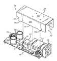
- FIG. 10shows PCB 56 and cooling tunnel 200 installed in compact case 25 of audio amplifier 24 .
- Cooling fan 216is disposed in compact case 25 adjacent to opening 217 of cooling tunnel 200 to draw air out of the compact case. Cooling fan 216 can also be placed on top surface 202 . Fresh air is drawn in through opening 218 and through notches 220 of cooling tunnel 200 and flows across the electrical components of PCB 56 . The heated air is then exhausted out opening 217 by cooling fan 216 .
- the major heat-generating componentse.g., transformer 222 , coils 224 , electrolytic capacitors 226 , power MOSFETs 62 - 64 , rectifier blocks 74 , 76 , and output stage blocks 82 , 84 are located on PCB 56 near opening 218 or inside cooling tunnel 200 .
- the air flow drawn into cooling tunnel 200 through opening 218provide maximum heat dissipation and maintain a proportional thermal range for each electrical component within its thermal design parameters.
- the opening 218maintains a balanced air flow across the electrical components of PCB 56 .
- Notch 220directs targeted air flow across power MOSFETs 62 and 64 and other major heat-generating electrical components.
- the deeper side 206also aids with maximum air flow efficiency from cooling fan 216 .
- a thermo-couplecan be attached to a component of PCB 56 to regulate speed of cooling fan 216 and the volume of air flow through cooling tunnel 200 .
- the audio amplifier circuitcan generate a high power rating greater than 500 W, up to 1000 W, into 4-ohm speaker load, in a compact case.
- the higher power ratingis achieved by limiting peak voltage and current in the output stage amplifiers to prevent hard clipping to a square wave.
- the peak voltage and current limiting circuitmaintains controlled operation of the power amplifiers and power conversion circuit during all playing levels.
- the additional power from the DC/DC power convertergenerates more heat which is dissipated with a cooling tunnel that channels maximum air flow over the major heat-generating electrical components, including the power switching transistors in the DC/DC converter.
- the cooling tunnelprovides the necessary thermal management within the space limitations of the compact case.
Landscapes
- Engineering & Computer Science (AREA)
- Physics & Mathematics (AREA)
- Acoustics & Sound (AREA)
- Multimedia (AREA)
- Signal Processing (AREA)
- Power Engineering (AREA)
- Amplifiers (AREA)
Abstract
Description
Claims (33)
Priority Applications (1)
| Application Number | Priority Date | Filing Date | Title |
|---|---|---|---|
| US12/570,910US8130495B2 (en) | 2009-09-30 | 2009-09-30 | Audio amplifier in compact case with peak voltage and current limiting circuit and thermal cooling tunnel |
Applications Claiming Priority (1)
| Application Number | Priority Date | Filing Date | Title |
|---|---|---|---|
| US12/570,910US8130495B2 (en) | 2009-09-30 | 2009-09-30 | Audio amplifier in compact case with peak voltage and current limiting circuit and thermal cooling tunnel |
Publications (2)
| Publication Number | Publication Date |
|---|---|
| US20110075359A1 US20110075359A1 (en) | 2011-03-31 |
| US8130495B2true US8130495B2 (en) | 2012-03-06 |
Family
ID=43780161
Family Applications (1)
| Application Number | Title | Priority Date | Filing Date |
|---|---|---|---|
| US12/570,910Expired - Fee RelatedUS8130495B2 (en) | 2009-09-30 | 2009-09-30 | Audio amplifier in compact case with peak voltage and current limiting circuit and thermal cooling tunnel |
Country Status (1)
| Country | Link |
|---|---|
| US (1) | US8130495B2 (en) |
Cited By (4)
| Publication number | Priority date | Publication date | Assignee | Title |
|---|---|---|---|---|
| US20110219942A1 (en)* | 2009-01-10 | 2011-09-15 | Kevin Arthur Robertson | Audio coupling device to couple an electric musical instrument to a handheld computing device |
| CN105848457A (en)* | 2016-05-30 | 2016-08-10 | 佛山市南海蜚声演出器材制造有限公司 | Extremely compact type power amplifier |
| US10490175B2 (en)* | 2017-12-27 | 2019-11-26 | Casio Computer Co., Ltd. | Audio device and electronic instrument |
| US20230052653A1 (en)* | 2019-10-14 | 2023-02-16 | Google Llc | Passive thermal-control system of an electronic speaker device and associated electronic speaker devices |
Families Citing this family (7)
| Publication number | Priority date | Publication date | Assignee | Title |
|---|---|---|---|---|
| KR101802333B1 (en)* | 2011-10-17 | 2017-12-29 | 삼성전자주식회사 | Method for outputting an audio signal and apparatus for outputting an audio signal thereof |
| CN203278615U (en)* | 2013-05-22 | 2013-11-06 | Abb技术有限公司 | A power module for a medium-high voltage inverter and an inverter including the same |
| CN107612366B (en)* | 2017-11-03 | 2023-04-07 | 张家港水云新能源科技有限公司 | High-power low-voltage large-current output direct-current power supply based on silicon carbide |
| US10755885B2 (en)* | 2018-04-11 | 2020-08-25 | Echowell Electronic Co., Ltd. | Vacuum tube rear device |
| CN108513208A (en)* | 2018-06-12 | 2018-09-07 | 江苏吉意信息技术有限公司 | A kind of mini combination audio of electron tube |
| CN108882647B (en)* | 2018-08-09 | 2020-05-01 | 安徽诺希电气设备科技有限公司 | Electronic instrument for radiating by accelerating air flow rate |
| US11178796B2 (en)* | 2018-09-26 | 2021-11-16 | Rockwell Automation Technologies, Inc. | Power conversion equipment cooling with cyclonic airborne particle reduction |
Citations (10)
| Publication number | Priority date | Publication date | Assignee | Title |
|---|---|---|---|---|
| US5689403A (en)* | 1994-12-27 | 1997-11-18 | Motorola, Inc. | Intercooled electronic device |
| US5726603A (en)* | 1994-07-14 | 1998-03-10 | Eni Technologies, Inc. | Linear RF power amplifier |
| US5946188A (en)* | 1998-07-29 | 1999-08-31 | Epsilon Electronics, Inc. | Car amplifier incorporating a peltier device for cooling |
| US6259798B1 (en)* | 1997-07-18 | 2001-07-10 | Mackie Designs Inc. | Passive radiator cooled electronics/heat sink housing for a powered speaker |
| US20040022024A1 (en)* | 2002-07-31 | 2004-02-05 | Infineon Technologies North America Corp. | Cooling hood for circuit board |
| US20040036563A1 (en)* | 2002-04-04 | 2004-02-26 | Seaton David W. | Heat dissipation system for audio amplifier |
| US6731502B1 (en)* | 2002-11-14 | 2004-05-04 | Inventec Corporation | Heat dissipation device for server |
| US20050057899A1 (en)* | 2003-09-16 | 2005-03-17 | Charles Lord | Compact electronics plenum |
| US20050135068A1 (en)* | 2003-12-17 | 2005-06-23 | Huff Brian E. | Electronic equipment enclosure |
| US7039374B2 (en)* | 2001-04-25 | 2006-05-02 | Fujitsu Limited | Transmitting and amplifying unit for wireless communication device |
- 2009
- 2009-09-30USUS12/570,910patent/US8130495B2/ennot_activeExpired - Fee Related
Patent Citations (13)
| Publication number | Priority date | Publication date | Assignee | Title |
|---|---|---|---|---|
| US5726603A (en)* | 1994-07-14 | 1998-03-10 | Eni Technologies, Inc. | Linear RF power amplifier |
| US5689403A (en)* | 1994-12-27 | 1997-11-18 | Motorola, Inc. | Intercooled electronic device |
| US6259798B1 (en)* | 1997-07-18 | 2001-07-10 | Mackie Designs Inc. | Passive radiator cooled electronics/heat sink housing for a powered speaker |
| US5946188A (en)* | 1998-07-29 | 1999-08-31 | Epsilon Electronics, Inc. | Car amplifier incorporating a peltier device for cooling |
| US7039374B2 (en)* | 2001-04-25 | 2006-05-02 | Fujitsu Limited | Transmitting and amplifying unit for wireless communication device |
| US6853553B2 (en)* | 2002-04-04 | 2005-02-08 | Gibson Guitar Corp. | Heat dissipation system for audio amplifier |
| US20040036563A1 (en)* | 2002-04-04 | 2004-02-26 | Seaton David W. | Heat dissipation system for audio amplifier |
| US6721180B2 (en)* | 2002-07-31 | 2004-04-13 | Infineon Technologies Ag | Cooling hood for circuit board |
| US20040022024A1 (en)* | 2002-07-31 | 2004-02-05 | Infineon Technologies North America Corp. | Cooling hood for circuit board |
| US6731502B1 (en)* | 2002-11-14 | 2004-05-04 | Inventec Corporation | Heat dissipation device for server |
| US20040095724A1 (en)* | 2002-11-14 | 2004-05-20 | Cheng-Chung Hsu | Heat dissipation device for server |
| US20050057899A1 (en)* | 2003-09-16 | 2005-03-17 | Charles Lord | Compact electronics plenum |
| US20050135068A1 (en)* | 2003-12-17 | 2005-06-23 | Huff Brian E. | Electronic equipment enclosure |
Non-Patent Citations (3)
| Title |
|---|
| ICEpower Amplifier with integrated ICEpower Supply Datasheet, version 1.1, Bang & Olufsen ICEpower a/s, pp. 1-27, Sep. 30, 2009. |
| Icepower ASX2 Series, Bang & Olufsen ICEpower a/s, pp. 1-16, Dec. 2008. |
| Shuttle Max 6.0 Owner's Manual, Genz Benz, Rev. 2, pp. 1-10, Jan. 1, 2009. |
Cited By (6)
| Publication number | Priority date | Publication date | Assignee | Title |
|---|---|---|---|---|
| US20110219942A1 (en)* | 2009-01-10 | 2011-09-15 | Kevin Arthur Robertson | Audio coupling device to couple an electric musical instrument to a handheld computing device |
| US8916761B2 (en)* | 2009-01-10 | 2014-12-23 | Kevin Arthur Robertson | Audio coupling device to couple an electric musical instrument to a handheld computing device |
| CN105848457A (en)* | 2016-05-30 | 2016-08-10 | 佛山市南海蜚声演出器材制造有限公司 | Extremely compact type power amplifier |
| US10490175B2 (en)* | 2017-12-27 | 2019-11-26 | Casio Computer Co., Ltd. | Audio device and electronic instrument |
| US20230052653A1 (en)* | 2019-10-14 | 2023-02-16 | Google Llc | Passive thermal-control system of an electronic speaker device and associated electronic speaker devices |
| US12176260B2 (en)* | 2019-10-14 | 2024-12-24 | Google Llc | Passive thermal-control system of an electronic speaker device and associated electronic speaker devices |
Also Published As
| Publication number | Publication date |
|---|---|
| US20110075359A1 (en) | 2011-03-31 |
Similar Documents
| Publication | Publication Date | Title |
|---|---|---|
| US8130495B2 (en) | Audio amplifier in compact case with peak voltage and current limiting circuit and thermal cooling tunnel | |
| US9008333B2 (en) | Guitar amplifier | |
| EP2215856B1 (en) | An electrostatic speaker system | |
| US20150201255A1 (en) | Portable Studio Monitor System | |
| US4991221A (en) | Active speaker system and components therefor | |
| US8386242B2 (en) | Method, medium and apparatus enhancing a bass signal using an auditory property | |
| US20090136061A1 (en) | Audio level compressor | |
| US20140169588A1 (en) | Boosted Differential Class H Amplifier | |
| CN201590835U (en) | High-fidelity sound reproduction system | |
| JP2005508105A (en) | Electric to acoustic converter | |
| JP3296311B2 (en) | Sound equipment | |
| Bogdan-Flavius et al. | Enhancing Audio Performance: Noise Reduction and Efficiency in Class AB Amplifier Design | |
| US20070189572A1 (en) | Loudspeaker system for acoustic instruments and method therefor | |
| US11101779B2 (en) | Amplifying device | |
| KR101094004B1 (en) | Digital Audio Amplifier with Speaker Current Feedback | |
| US8822802B1 (en) | System and method for generating musical distortion in an audio amplifier | |
| US20200357380A1 (en) | Electronic effects device and method | |
| Rahman et al. | Design and implementation of a high performance AB-class amplifier using TDA2030 | |
| US20080267418A1 (en) | Method and apparatus for dynamically adjusting the spectral content of an audio signal | |
| JP4494902B2 (en) | Sound playback device | |
| Lee et al. | High-level power management of audio power amplifiers for portable multimedia applications | |
| Militaru et al. | Technical Review of Class TD Audio Power Amplifiers | |
| US20230261617A1 (en) | Pre-amplification conditioning circuit for a transducer audio device | |
| KR20250134077A (en) | musical instrument amplifier | |
| US20070248233A1 (en) | Method and apparatus for dynamically adjusting the spectral content of an audio signal |
Legal Events
| Date | Code | Title | Description |
|---|---|---|---|
| AS | Assignment | Owner name:KMC MUSIC, INC., CONNECTICUT Free format text:ASSIGNMENT OF ASSIGNORS INTEREST;ASSIGNORS:FIELD, ANDREW L.;ANDRES, SCOTT L.;GENZLER, JEFFREY D.;SIGNING DATES FROM 20090928 TO 20090929;REEL/FRAME:023308/0613 | |
| STCF | Information on status: patent grant | Free format text:PATENTED CASE | |
| CC | Certificate of correction | ||
| AS | Assignment | Owner name:JPMORGAN CHASE BANK, N.A., AS ADMINISTRATIVE AGENT Free format text:SECURITY AGREEMENT;ASSIGNOR:KMC MUSIC, INC. (F/K/A KAMAN MUSIC CORPORATION);REEL/FRAME:030441/0630 Effective date:20130403 | |
| AS | Assignment | Owner name:JPMORGAN CHASE BANK, N.A., AS ADMINISTRATIVE AGENT Free format text:SECURITY AGREEMENT;ASSIGNOR:KMC MUSIC, INC. (F/K/A KAMAN MUSIC CORPORATION);REEL/FRAME:030486/0270 Effective date:20130516 | |
| AS | Assignment | Owner name:KMC MUSIC, INC. (F/K/A KAMAN MUSIC CORPORATION), C Free format text:PARTIAL RELEASE OF GRANT OF SECURITY INTEREST IN PATENT RIGHTS RECORDED AT REEL 030441/FRAME 0630;ASSIGNOR:JPMORGAN CHASE BANK, N.A.;REEL/FRAME:034914/0581 Effective date:20150206 Owner name:KMC MUSIC, INC. (F/K/A KAMAN MUSIC CORPORATION), C Free format text:PARTIAL RELEASE OF GRANT OF SECURITY INTEREST IN PATENT RIGHTS RECORDED AT REEL 030486/FRAME 0270;ASSIGNOR:JPMORGAN CHASE BANK, N.A.;REEL/FRAME:034914/0640 Effective date:20150206 | |
| AS | Assignment | Owner name:JAM INDUSTRIES USA, LLC, CANADA Free format text:ASSIGNMENT OF ASSIGNORS INTEREST;ASSIGNOR:KMC MUSIC, INC.;REEL/FRAME:034970/0380 Effective date:20150206 | |
| AS | Assignment | Owner name:JAM INDUSTRIES USA, LLC, CANADA Free format text:CORRECTIVE ASSIGNMENT TO CORRECT THE RECEIVING PARTY DATA - STREET ADDRESS PREVIOUSLY RECORDED ON REEL 034970 FRAME 380. ASSIGNOR(S) HEREBY CONFIRMS THE 21000 TRANS-CANADA HIGHWAY;ASSIGNOR:KMC MUSIC, INC.;REEL/FRAME:035269/0609 Effective date:20150206 | |
| FPAY | Fee payment | Year of fee payment:4 | |
| AS | Assignment | Owner name:FENDER MUSICAL INSTRUMENTS CORPORATION, ARIZONA Free format text:RELEASE BY SECURED PARTY;ASSIGNOR:JPMORGAN CHASE BANK, N.A., AS ADMINISTRATIVE AGENT;REEL/FRAME:041649/0926 Effective date:20170203 Owner name:KMC MUSIC, INC. (F/K/A KAMAN MUSIC CORPORATION), A Free format text:RELEASE BY SECURED PARTY;ASSIGNOR:JPMORGAN CHASE BANK, N.A., AS ADMINISTRATIVE AGENT;REEL/FRAME:041649/0926 Effective date:20170203 Owner name:ROKR DISTRIBUTION US, INC. (FORMERLY KMC MUSIC, IN Free format text:RELEASE BY SECURED PARTY;ASSIGNOR:JPMORGAN CHASE BANK, N.A.;REEL/FRAME:041651/0785 Effective date:20170203 Owner name:FENDER MUSICAL INSTRUMENTS CORPORATION, ARIZONA Free format text:RELEASE BY SECURED PARTY;ASSIGNOR:JPMORGAN CHASE BANK, N.A.;REEL/FRAME:041651/0785 Effective date:20170203 | |
| FEPP | Fee payment procedure | Free format text:MAINTENANCE FEE REMINDER MAILED (ORIGINAL EVENT CODE: REM.); ENTITY STATUS OF PATENT OWNER: LARGE ENTITY | |
| LAPS | Lapse for failure to pay maintenance fees | Free format text:PATENT EXPIRED FOR FAILURE TO PAY MAINTENANCE FEES (ORIGINAL EVENT CODE: EXP.); ENTITY STATUS OF PATENT OWNER: LARGE ENTITY | |
| STCH | Information on status: patent discontinuation | Free format text:PATENT EXPIRED DUE TO NONPAYMENT OF MAINTENANCE FEES UNDER 37 CFR 1.362 | |
| FP | Lapsed due to failure to pay maintenance fee | Effective date:20200306 |