US8130159B2 - Electromagnetic field generation antenna for a transponder - Google Patents
Electromagnetic field generation antenna for a transponderDownload PDFInfo
- Publication number
- US8130159B2 US8130159B2US12/560,184US56018409AUS8130159B2US 8130159 B2US8130159 B2US 8130159B2US 56018409 AUS56018409 AUS 56018409AUS 8130159 B2US8130159 B2US 8130159B2
- Authority
- US
- United States
- Prior art keywords
- inductive element
- resonant circuit
- antenna
- planar
- windings
- Prior art date
- Legal status (The legal status is an assumption and is not a legal conclusion. Google has not performed a legal analysis and makes no representation as to the accuracy of the status listed.)
- Expired - Fee Related
Links
Images


Classifications
- G—PHYSICS
- G06—COMPUTING OR CALCULATING; COUNTING
- G06K—GRAPHICAL DATA READING; PRESENTATION OF DATA; RECORD CARRIERS; HANDLING RECORD CARRIERS
- G06K7/00—Methods or arrangements for sensing record carriers, e.g. for reading patterns
- G06K7/10—Methods or arrangements for sensing record carriers, e.g. for reading patterns by electromagnetic radiation, e.g. optical sensing; by corpuscular radiation
- G06K7/10009—Methods or arrangements for sensing record carriers, e.g. for reading patterns by electromagnetic radiation, e.g. optical sensing; by corpuscular radiation sensing by radiation using wavelengths larger than 0.1 mm, e.g. radio-waves or microwaves
- G06K7/10316—Methods or arrangements for sensing record carriers, e.g. for reading patterns by electromagnetic radiation, e.g. optical sensing; by corpuscular radiation sensing by radiation using wavelengths larger than 0.1 mm, e.g. radio-waves or microwaves using at least one antenna particularly designed for interrogating the wireless record carriers
- G06K7/10346—Methods or arrangements for sensing record carriers, e.g. for reading patterns by electromagnetic radiation, e.g. optical sensing; by corpuscular radiation sensing by radiation using wavelengths larger than 0.1 mm, e.g. radio-waves or microwaves using at least one antenna particularly designed for interrogating the wireless record carriers the antenna being of the far field type, e.g. HF types or dipoles
- G—PHYSICS
- G06—COMPUTING OR CALCULATING; COUNTING
- G06K—GRAPHICAL DATA READING; PRESENTATION OF DATA; RECORD CARRIERS; HANDLING RECORD CARRIERS
- G06K7/00—Methods or arrangements for sensing record carriers, e.g. for reading patterns
- G06K7/0008—General problems related to the reading of electronic memory record carriers, independent of its reading method, e.g. power transfer
- G—PHYSICS
- G06—COMPUTING OR CALCULATING; COUNTING
- G06K—GRAPHICAL DATA READING; PRESENTATION OF DATA; RECORD CARRIERS; HANDLING RECORD CARRIERS
- G06K7/00—Methods or arrangements for sensing record carriers, e.g. for reading patterns
- G06K7/10—Methods or arrangements for sensing record carriers, e.g. for reading patterns by electromagnetic radiation, e.g. optical sensing; by corpuscular radiation
- G06K7/10009—Methods or arrangements for sensing record carriers, e.g. for reading patterns by electromagnetic radiation, e.g. optical sensing; by corpuscular radiation sensing by radiation using wavelengths larger than 0.1 mm, e.g. radio-waves or microwaves
- G06K7/10158—Methods or arrangements for sensing record carriers, e.g. for reading patterns by electromagnetic radiation, e.g. optical sensing; by corpuscular radiation sensing by radiation using wavelengths larger than 0.1 mm, e.g. radio-waves or microwaves methods and means used by the interrogation device for reliably powering the wireless record carriers using an electromagnetic interrogation field
- G06K7/10178—Methods or arrangements for sensing record carriers, e.g. for reading patterns by electromagnetic radiation, e.g. optical sensing; by corpuscular radiation sensing by radiation using wavelengths larger than 0.1 mm, e.g. radio-waves or microwaves methods and means used by the interrogation device for reliably powering the wireless record carriers using an electromagnetic interrogation field including auxiliary means for focusing, repeating or boosting the electromagnetic interrogation field
- G—PHYSICS
- G06—COMPUTING OR CALCULATING; COUNTING
- G06K—GRAPHICAL DATA READING; PRESENTATION OF DATA; RECORD CARRIERS; HANDLING RECORD CARRIERS
- G06K7/00—Methods or arrangements for sensing record carriers, e.g. for reading patterns
- G06K7/10—Methods or arrangements for sensing record carriers, e.g. for reading patterns by electromagnetic radiation, e.g. optical sensing; by corpuscular radiation
- G06K7/10009—Methods or arrangements for sensing record carriers, e.g. for reading patterns by electromagnetic radiation, e.g. optical sensing; by corpuscular radiation sensing by radiation using wavelengths larger than 0.1 mm, e.g. radio-waves or microwaves
- G06K7/10316—Methods or arrangements for sensing record carriers, e.g. for reading patterns by electromagnetic radiation, e.g. optical sensing; by corpuscular radiation sensing by radiation using wavelengths larger than 0.1 mm, e.g. radio-waves or microwaves using at least one antenna particularly designed for interrogating the wireless record carriers
- G06K7/10336—Methods or arrangements for sensing record carriers, e.g. for reading patterns by electromagnetic radiation, e.g. optical sensing; by corpuscular radiation sensing by radiation using wavelengths larger than 0.1 mm, e.g. radio-waves or microwaves using at least one antenna particularly designed for interrogating the wireless record carriers the antenna being of the near field type, inductive coil
Definitions
- the present inventionrelates to systems using electromagnetic transponders, that is, transmitters and/or receivers (generally mobile) capable of being interrogated in a contactless and wireless manner by a unit (generally fixed), called a read and/or write terminal.
- transpondersextract the power supply required by the electronic circuits included therein from the high-frequency field radiated by an antenna of the read-write terminal.
- the present inventionmore specifically relates to a read and/or write terminal for electromagnetic transponders as well as to the antenna that it includes.
- FIG. 1very schematically shows a conventional example of a read/write terminal 1 associated with a transponder 10 .
- terminal 1is essentially formed of a series oscillating circuit formed of an inductance L 1 in series with a capacitor C 1 and a resistor R 1 .
- This oscillating circuitis controlled by a device 2 including, among others, an amplifier or antenna coupler and a control circuit exploiting the received data provided, in particular, with a modulator/demodulator and a microprocessor for processing the control signals and the data.
- the oscillating circuitis excited by a voltage Vg provided by device 2 between terminals 3 and 4 .
- Circuit 2generally communicates with different input/output circuits (keyboard, screen, means of exchange with a server, etc.) and/or processing circuits, not shown.
- the circuits of the read/write terminaldraw the power necessary to their operation from a supply circuit (not shown) connected, for example, to the electric supply system.
- a transponder 10intended for cooperating with a terminal 1 , essentially includes a parallel oscillating circuit.
- This circuitis formed of an inductance L 2 in parallel with a capacitor C 2 between two input terminals 11 , 12 of a control and processing circuit 13 .
- Terminals 11 , 12are in practice connected to the input of a rectifying means (not shown), the outputs of which form D.C. supply terminals of the circuits internal to transponder 10 .
- These circuitsgenerally include, essentially, a microprocessor, a memory, a demodulator of the signals that may be received from terminal 1 , and a modulator for transmitting information to the terminal.
- the oscillating circuits of the terminal and of the transponderare generally tuned on a same frequency corresponding to the frequency of excitation signal Vg of the terminal's oscillating circuit.
- This high-frequency signal(for example, at 13.56 MHz) is not only used as a carrier of data transmission from the terminal to the transponder, but also as a remote supply carrier for the transponders located in the terminal's field.
- a transponder 10is located in the field of a terminal 1 , a high-frequency voltage is generated across terminals 11 and 12 of the transponder's resonant circuit. This voltage, after being rectified and possibly clipped, provides the supply voltage of electronic circuits 13 of the transponder.
- the high-frequency carrier transmitted by the terminalis generally modulated in amplitude by said terminal according to different coding techniques to transmit data and/or control signals to one or several transponders in the field.
- the data transmission from the transponder to a terminalis generally performed by modulating the load formed by resonant circuit L 2 , C 2 .
- the load variationis performed at the rate of a sub-carrier having a frequency (for example, 847.5 kHz) smaller than that of the carrier.
- This load variationcan then be detected by the terminal as an amplitude variation or as a phase variation by means, for example, of a measurement of the voltage across capacitor C 1 or of current Ig in the oscillating circuit.
- the measurement signalhas been symbolized by a connection 5 in dotted lines connecting the midpoint of the series connection of inductance L 1 and capacitor C 1 to circuit 2 .
- a problem which arises in conventional transponder systemsis that they generally have a limited range.
- the system rangecorresponds to the limiting distance beyond which the field sensed by a transponder is too small to enable extraction of the power necessary for its operation therefrom.
- the limited rangeis essentially due to the maximum admissible magnetic field, which is set by standards.
- the diameter of the antennais desired to be increased, to avoid exceeding this maximum allowed magnetic field.
- increasing the diameteramounts to increasing excitation current Ig in proportions that are not desirable, among others, for power consumption reasons.
- An object of the present inventionis to improve the range of electromagnetic transponder read/write terminals.
- the present inventionmore specifically aims at providing a novel long-range electromagnetic field generation antenna.
- the present inventionalso aims at requiring no modification of the transponders and, accordingly, at being able to operate with any conventional transponder.
- the present inventionalso aims at reducing or minimizing the power consumption of the terminal.
- the present inventionprovides an antenna for generating an electromagnetic field for an electromagnetic transponder, including a first inductive element intended for being connected to two terminals of application of an excitation voltage, and a parallel resonant circuit coupled with the first inductive element.
- said resonant circuitincludes a second inductive element, the value of which is chosen to be greater than the value of the first inductive element with a ratio depending on a desired field amplification.
- the first inductive elementis formed of several inductances associated in a network.
- the inductive element(s)are formed of planar windings.
- the two inductive elementsare in parallel planes.
- the distance that separates the respective planes of the inductive elementsis chosen according to the power consumption of the transponders for which the antenna is intended and to the desired range.
- the present inventionalso provides a terminal for generating a high-frequency electromagnetic field for at least one transponder entering this field, the terminal including a resonant circuit, magnetically coupled to an excitation circuit including a first inductive element and having no capacitive element.
- the resonant circuitis formed of a second inductive element and of a capacitive element in parallel, and is tuned to the frequency of an excitation signal of the first inductive element.
- said resonant circuitincludes a control switch.
- FIG. 1shows a conventional example of a transponder system of the type to which the present invention applies;
- FIG. 2schematically shows a first embodiment of a read and/or write terminal, provided with an antenna according to the present invention, and associated with a conventional transponder;
- FIGS. 3A and 3Bshow an antenna according to a second embodiment of the present invention.
- FIG. 4shows an alternative embodiment of a terminal according to the present invention.
- a feature of the present inventionis to provide the antenna of a read and/or write terminal in the form of an LR circuit coupled to a resonant LC circuit.
- the LR circuitis excited by the high-frequency generator of the terminal.
- the excitation frequencyis, conventionally, that of the remote supply carrier and of the possible data to be transmitted.
- the resonant circuitforms a rejector circuit formed of an inductance and of a capacitor. It is in practice an RLC circuit with as small a resistance as possible corresponding to the series resistances of the inductance and of the capacitor.
- Another feature of the present inventionis to provide a value of the inductance of the rejector circuit greater than that of the LR excitation circuit.
- the voltage developed across the capacitor of the rejector circuitis greater than the excitation voltage of the LR circuit.
- the quality factor of the rejector circuitis desired to be increased or maximized to favor the amplification created by its coupling with the LR excitation circuit.
- the quality factoris inversely proportional to the sum of the series resistances and to the square root of the capacitance of the rejector circuit, and directly proportional to the square root of its inductance. Accordingly, the inductance is desired to be increased or maximized and the series resistances and the capacitance are desired to be reduced or minimized.
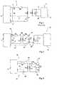
- FIG. 2schematically shows a first embodiment of a read and/or write terminal according to the present invention.
- a terminal 20includes circuits 2 for processing, controlling, and analyzing data to be exchanged with a transponder 10 , also conventional.
- a high-frequency voltage Vg used as a remote power supply carrier and/or as a modulation carrier for a transponderis provided across output terminals 3 and 4 of circuit 2 .
- terminals 3 and 4are connected to a series LR circuit formed of a resistor R 1 in series with an inductance Lp.
- Inductance Lpis intended to be coupled with an inductance Lb of a rejector circuit 21 associated with the LR circuit.
- Circuit 21also includes a capacitor Cb, the two electrodes of which are respectively connected to the two terminals 24 and 25 of inductance Lb.
- the inductive LR circuitconnected across terminals 3 and 4 of circuit 2 , includes no capacitor.
- this tuningis transferred to rejector circuit 21 .
- the respective values of inductance Lb and of capacitance Cbare selected so that the resonance frequency of this circuit corresponds to the remote supply carrier of the system (for example, 13.56 MHz).
- inductances Lp and Lbare, preferably, made in the form of planar inductances having one or several spirals.
- the inductancesare placed in parallel planes to increase or maximize the magnetic coupling between them. This coupling is symbolized in FIG. 2 by mutual inductance M between the LR and LC circuits.
- Transponder 10is a conventional transponder, the present invention requiring no modification of the transponder for its implementation. When transponder 10 is present in the terminal's field, it is in magnetic coupling (mutual inductance M′) with the rejector circuit, from which it draws the power necessary to its operation.
- the fact of placing a transponder in the antenna's fieldamounts to increasing the series resistance of rejector circuit 21 , and thus reduces its quality factor and the current flow therethrough. This causes power consumption on the side of excitation circuit R 1 -Lp.
- the terminal's generatorcan just provide an energizing current to the rejector circuit where the current and the voltage are naturally high.
- Inductance Lpis chosen to be as small as possible to improve or optimize the system efficiency and maximize the use of the installed power of the generator providing voltage Vg.
- the value of inductance Lb of rejector circuit 21is chosen to be as high as possible to increase or maximize the system range. Indeed, the higher ratio Lb/Lp, the greater the ratio between the voltage developed across capacitor Cb and voltage Vg.
- the interval between the planar inductances, arranged in parallel planesis adapted to the transponders for which the terminal is intended.
- the charge level represented by different transpondersin particular, according to whether they include or not a microprocessor
- the coupling between the excitation and rejector circuitscan be improved or optimized.
- the antenna's inductanceswill be drawn away from each other to increase or maximize the overvoltage generated across the rejector circuit. For example, an interval ranging between approximately 0.5 cm and a few centimeters will be selected.
- the coupling between inductancesmust be maximized so that the load represented by the transponders does not alter too much the quality factor of the rejector circuit.
- the antenna's inductancesare then placed as close as possible to each other. The interval of course depends, among others, on the diameter of the inductances and on the quality coefficient of the rejector circuit.
- An advantage of the present inventionis that it enables increasing the range of a read and/or write terminal for a given voltage Vg and excitation current Ig.
- Another advantage of the present inventionis that it requires no modification of existing transponders.
- the detection of a back modulation coming from a transpondercan be performed either on the LR circuit or in LC circuit 21 .
- a current transformer 22having the function of measuring the current in rejector circuit 21 has been symbolized.
- a connection 23provides the result of this measurement to circuit 2 .
- the measurementmay be performed in the LR circuit. However, it is easier to detect variations in the rejector circuit where the signal levels are higher. It will however be ascertained that this measurement disturbs as little as possible the quality factor of the rejector circuit. For example, if a voltage measurement is performed across capacitor Cb, it will be ascertained to use a measurement element with a high input impedance.
- the present inventionenables increasing the transmitted magnetic field without increasing either the current provided by the generator or voltage Vg, and thus without increasing the installed terminal power.
- the present inventionenables easy use of antennas of large dimensions, which is difficult with conventional terminals without increasing the generator voltage to provide the sufficient current.
- Another advantage of the present inventionis that it eases the impedance matching of the antenna with respect to control circuit 2 .
- Rprepresents the following real part:
- Rp⁇ 2 ⁇ k pb 2 ⁇ Lp ⁇ Lb Rb , and
- the ratio between inductances Lb and Lpmay, for example, be modified, or a resistor may be introduced in parallel in circuit 21 .
- imaginary part Xp of impedance Zpeqis a function of inductance Lp, which is reduced or minimized.
- the impedancemay, as a first approximation, be considered as being purely resistive. It is thus particularly easy to obtain an off-load impedance matching (for example, at 50 ⁇ ).
- An advantagethen is that the antenna of the read/write terminal can be easily moved aside from its control circuits. A 50- ⁇ matched impedance cable is sufficient.
- a transponderwhen a transponder is present in the field, it has an influence upon the impedance seen by the generator (at the denominator of the real part).
- FIGS. 3A and 3Bshow the two sides of an antenna according to a preferred embodiment of the present invention.
- inductive excitation element Lpis formed of several inductances 31 , 32 , 33 , 34 , 35 , 36 , and 37 in a network, that is, electrically in parallel.
- Inductances 31 , 32 , 33 , 34 , 35 , 36 , and 37are coplanar.
- the inductancesare, preferably, distributed in a honeycomb.
- Each inductance 31 , 32 , 33 , 34 , 35 , 36 , and 37includes, for example, a single hexagonal spiral. The number of spirals of these inductances may be adapted to the value desired for the resulting inductive element Lp.
- Terminals 38 and 39 of interconnection of the respective terminals of inductances 31 to 37form the terminals of element Lp.
- the inductancesare for example formed by depositions of conductive tracks on a printed circuit wafer.
- a first end of each inductanceis connected to terminal 38 .
- This connectionis performed by means of vias 41 and of conductive tracks 42 of the two wafer surfaces ( FIGS. 3A and 3B ).
- the second end of each inductanceis connected to terminal 39 by means of vias 43 and of tracks 44 .
- the network association of the inductancesmust be such that all inductances in the network generate fields, the lines of which add (all are in the same direction).
- Inductance Lbis formed on the second wafer surface.
- this inductanceis formed of a single spiral 40 approximately delimiting a surface equivalent to that of all the network-connected spirals of inductive element Lp. It thus follows the external contour of the honeycomb.
- the end terminals of spiral 40define terminals 24 and 25 of inductance Lb intended for being connected to capacitor Cb (not shown).
- An advantage of using a network inductive element on the side of the LR circuitis that the voltage and current ratio is increased or maximized between the rejector circuit and the excitation circuit. Indeed, the ratio between the inductances of the rejector circuit and of the excitation circuit is increased.
- FIG. 4shows another embodiment of a read and/or write terminal 45 according to the present invention.
- This embodimentmore specifically applies to a terminal intended for operating either in relatively remote coupling with a transponder, or in very close coupling therewith. Indeed, in some applications, it is desired to only exchange information between a transponder and the terminal when said transponder is very close to the terminal. This, to avoid that a pirate device intercepts the data exchanges. In such a case, to use a single terminal, the data exchange sequences must conventionally be adapted and software controls must be performed for an operation in very close coupling allowed to a single transponder.
- FIG. 4illustrates that the implementation of the present invention greatly eases an operation in extreme closeness of a read and/or write terminal.
- a switch 46is provided in rejector circuit 21 ′. This switch is placed in parallel with inductance Lb and is intended for short-circuiting the rejector circuit and, accordingly, eliminating the coupling with excitation circuit LR. Switch 46 is controlled by circuit 2 , via a connection 47 .
- switch 46when the terminal is desired to be dedicated to an operation in extreme closeness, switch 46 is closed. In this case, a transponder that wants to exchange data with the terminal must be placed almost on the terminal's antenna to obtain a magnetic coupling with inductive element Lp. The smaller the value of this inductance, the more it will be necessary for the transponder to be close to the terminal. The operation will here be close to an operation as a transformer. When switch 46 is open, the rejector circuit performs its function and the range of the read and/or write terminal is maximum.
- the switchis placed in series in the rejector circuit. The operation is then inverted and the opening of the switch turns off the rejector circuit. In this alternative, it will be ascertained that the series resistance of the switch is minimum.
- FIG. 4shows a current transformer 22 ′ in series with inductive element Lp, and measurement signal 23 ′ of which is sent to circuit 2 .
- This current transformerprovides a measurement of the current in the excitation circuit.
- Such an arrangementis here necessary at least for the operation in extreme closeness since a detection can no longer be performed by the rejector circuit. It is however possible to maintain the use of a measurement system, on the rejector circuit side, when the terminal operates in remote range.
Landscapes
- Engineering & Computer Science (AREA)
- Physics & Mathematics (AREA)
- Health & Medical Sciences (AREA)
- Toxicology (AREA)
- Electromagnetism (AREA)
- Artificial Intelligence (AREA)
- Computer Vision & Pattern Recognition (AREA)
- General Physics & Mathematics (AREA)
- Theoretical Computer Science (AREA)
- Computer Networks & Wireless Communication (AREA)
- General Health & Medical Sciences (AREA)
- Near-Field Transmission Systems (AREA)
Abstract
Description
This application is a continuation of U.S. patent application Ser. No. 10/344,880, filed on Feb. 14, 2003, entitled “ELECTROMAGNETIC FIELD GENERATION ANTENNA FOR A TRANSPONDER,” which application is a U.S. National Stage application of International Application serial No. PCT/FR2001/02621, filed on Aug. 16, 2001, entitled “ANTENNA GENERATING AN ELECTROMAGNETIC FIELD FOR TRANSPONDER,” which application claims priority benefit of French patent application number 00/10699, filed on Aug. 17, 2000, entitled “ANTENNA GENERATING AN ELECTROMAGNETIC FIELD FOR TRANSPONDER,” which applications are hereby incorporated by reference to the maximum extent allowable by law.
1. Field of the Invention
The present invention relates to systems using electromagnetic transponders, that is, transmitters and/or receivers (generally mobile) capable of being interrogated in a contactless and wireless manner by a unit (generally fixed), called a read and/or write terminal. Generally, transponders extract the power supply required by the electronic circuits included therein from the high-frequency field radiated by an antenna of the read-write terminal. The present invention more specifically relates to a read and/or write terminal for electromagnetic transponders as well as to the antenna that it includes.
2. Discussion of the Related Art
Generally,terminal 1 is essentially formed of a series oscillating circuit formed of an inductance L1 in series with a capacitor C1 and a resistor R1. This oscillating circuit is controlled by adevice 2 including, among others, an amplifier or antenna coupler and a control circuit exploiting the received data provided, in particular, with a modulator/demodulator and a microprocessor for processing the control signals and the data. The oscillating circuit is excited by a voltage Vg provided bydevice 2 betweenterminals 3 and4.Circuit 2 generally communicates with different input/output circuits (keyboard, screen, means of exchange with a server, etc.) and/or processing circuits, not shown. The circuits of the read/write terminal draw the power necessary to their operation from a supply circuit (not shown) connected, for example, to the electric supply system.
Atransponder 10, intended for cooperating with aterminal 1, essentially includes a parallel oscillating circuit. This circuit is formed of an inductance L2 in parallel with a capacitor C2 between twoinput terminals processing circuit 13.Terminals terminal 1, and a modulator for transmitting information to the terminal.
The oscillating circuits of the terminal and of the transponder are generally tuned on a same frequency corresponding to the frequency of excitation signal Vg of the terminal's oscillating circuit. This high-frequency signal (for example, at 13.56 MHz) is not only used as a carrier of data transmission from the terminal to the transponder, but also as a remote supply carrier for the transponders located in the terminal's field. When atransponder 10 is located in the field of aterminal 1, a high-frequency voltage is generated acrossterminals electronic circuits 13 of the transponder.
The high-frequency carrier transmitted by the terminal is generally modulated in amplitude by said terminal according to different coding techniques to transmit data and/or control signals to one or several transponders in the field. In return, the data transmission from the transponder to a terminal is generally performed by modulating the load formed by resonant circuit L2, C2. The load variation is performed at the rate of a sub-carrier having a frequency (for example, 847.5 kHz) smaller than that of the carrier. This load variation can then be detected by the terminal as an amplitude variation or as a phase variation by means, for example, of a measurement of the voltage across capacitor C1 or of current Ig in the oscillating circuit. InFIG. 1 , the measurement signal has been symbolized by a connection5 in dotted lines connecting the midpoint of the series connection of inductance L1 and capacitor C1 tocircuit 2.
A problem which arises in conventional transponder systems is that they generally have a limited range. The system range corresponds to the limiting distance beyond which the field sensed by a transponder is too small to enable extraction of the power necessary for its operation therefrom. The limited range is essentially due to the maximum admissible magnetic field, which is set by standards. Conventionally, to increase the range, the diameter of the antenna is desired to be increased, to avoid exceeding this maximum allowed magnetic field. Now, increasing the diameter amounts to increasing excitation current Ig in proportions that are not desirable, among others, for power consumption reasons.
An object of the present invention is to improve the range of electromagnetic transponder read/write terminals.
The present invention more specifically aims at providing a novel long-range electromagnetic field generation antenna.
The present invention also aims at requiring no modification of the transponders and, accordingly, at being able to operate with any conventional transponder.
The present invention also aims at reducing or minimizing the power consumption of the terminal.
To achieve these and other objects, the present invention provides an antenna for generating an electromagnetic field for an electromagnetic transponder, including a first inductive element intended for being connected to two terminals of application of an excitation voltage, and a parallel resonant circuit coupled with the first inductive element.
According to an embodiment of the present invention, said resonant circuit includes a second inductive element, the value of which is chosen to be greater than the value of the first inductive element with a ratio depending on a desired field amplification.
According to an embodiment of the present invention, the first inductive element is formed of several inductances associated in a network.
According to an embodiment of the present invention, the inductive element(s) are formed of planar windings.
According to an embodiment of the present invention, the two inductive elements are in parallel planes.
According to an embodiment of the present invention, the distance that separates the respective planes of the inductive elements is chosen according to the power consumption of the transponders for which the antenna is intended and to the desired range.
The present invention also provides a terminal for generating a high-frequency electromagnetic field for at least one transponder entering this field, the terminal including a resonant circuit, magnetically coupled to an excitation circuit including a first inductive element and having no capacitive element.
According to an embodiment of the present invention, the resonant circuit is formed of a second inductive element and of a capacitive element in parallel, and is tuned to the frequency of an excitation signal of the first inductive element.
According to an embodiment of the present invention, said resonant circuit includes a control switch.
The foregoing objects, features and advantages of the present invention, will be discussed in detail in the following non-limiting description of specific embodiments in connection with the accompanying drawings.
The same elements have been referred to with the same references in the different drawings. For clarity, only those elements which are necessary to the understanding of the present invention have been illustrated in the drawings and will be described hereafter. In particular, the internal structures of the electronic circuits of a transponder and of a read and/or write terminal have not been detailed.
A feature of the present invention is to provide the antenna of a read and/or write terminal in the form of an LR circuit coupled to a resonant LC circuit. According to the present invention, the LR circuit is excited by the high-frequency generator of the terminal. The excitation frequency is, conventionally, that of the remote supply carrier and of the possible data to be transmitted. The resonant circuit forms a rejector circuit formed of an inductance and of a capacitor. It is in practice an RLC circuit with as small a resistance as possible corresponding to the series resistances of the inductance and of the capacitor.
Another feature of the present invention is to provide a value of the inductance of the rejector circuit greater than that of the LR excitation circuit. Thus, the voltage developed across the capacitor of the rejector circuit is greater than the excitation voltage of the LR circuit. According to the present invention, the quality factor of the rejector circuit is desired to be increased or maximized to favor the amplification created by its coupling with the LR excitation circuit. The quality factor is inversely proportional to the sum of the series resistances and to the square root of the capacitance of the rejector circuit, and directly proportional to the square root of its inductance. Accordingly, the inductance is desired to be increased or maximized and the series resistances and the capacitance are desired to be reduced or minimized.
Conventionally, a terminal20 according to the present invention includescircuits 2 for processing, controlling, and analyzing data to be exchanged with atransponder 10, also conventional. A high-frequency voltage Vg used as a remote power supply carrier and/or as a modulation carrier for a transponder is provided acrossoutput terminals 3 and4 ofcircuit 2. According to the present invention,terminals 3 and4 are connected to a series LR circuit formed of a resistor R1 in series with an inductance Lp. Inductance Lp is intended to be coupled with an inductance Lb of arejector circuit 21 associated with the LR circuit.Circuit 21 also includes a capacitor Cb, the two electrodes of which are respectively connected to the twoterminals terminals 3 and4 ofcircuit 2, includes no capacitor. Thus, there is no tuning of the excitation circuit on the remote supply carrier frequency. According to the present invention, this tuning is transferred torejector circuit 21. For the latter, the respective values of inductance Lb and of capacitance Cb are selected so that the resonance frequency of this circuit corresponds to the remote supply carrier of the system (for example, 13.56 MHz).
According to the present invention, inductances Lp and Lb are, preferably, made in the form of planar inductances having one or several spirals. The inductances are placed in parallel planes to increase or maximize the magnetic coupling between them. This coupling is symbolized inFIG. 2 by mutual inductance M between the LR and LC circuits.Transponder 10 is a conventional transponder, the present invention requiring no modification of the transponder for its implementation. Whentransponder 10 is present in the terminal's field, it is in magnetic coupling (mutual inductance M′) with the rejector circuit, from which it draws the power necessary to its operation.
The fact of placing a transponder in the antenna's field amounts to increasing the series resistance ofrejector circuit 21, and thus reduces its quality factor and the current flow therethrough. This causes power consumption on the side of excitation circuit R1-Lp. However, the terminal's generator can just provide an energizing current to the rejector circuit where the current and the voltage are naturally high.
Inductance Lp is chosen to be as small as possible to improve or optimize the system efficiency and maximize the use of the installed power of the generator providing voltage Vg. The value of inductance Lb ofrejector circuit 21 is chosen to be as high as possible to increase or maximize the system range. Indeed, the higher ratio Lb/Lp, the greater the ratio between the voltage developed across capacitor Cb and voltage Vg.
According to a preferred embodiment of the present invention, the interval between the planar inductances, arranged in parallel planes, is adapted to the transponders for which the terminal is intended. According to the charge level represented by different transponders (in particular, according to whether they include or not a microprocessor) and according to the desired range, the coupling between the excitation and rejector circuits can be improved or optimized. In the case of low-power consumption transponders and where a large range is desired, the antenna's inductances will be drawn away from each other to increase or maximize the overvoltage generated across the rejector circuit. For example, an interval ranging between approximately 0.5 cm and a few centimeters will be selected. Conversely, for transponders having a higher power consumption, the coupling between inductances must be maximized so that the load represented by the transponders does not alter too much the quality factor of the rejector circuit. The antenna's inductances are then placed as close as possible to each other. The interval of course depends, among others, on the diameter of the inductances and on the quality coefficient of the rejector circuit.
An advantage of the present invention is that it enables increasing the range of a read and/or write terminal for a given voltage Vg and excitation current Ig.
Another advantage of the present invention is that it requires no modification of existing transponders.
The detection of a back modulation coming from a transponder can be performed either on the LR circuit or inLC circuit 21. In the embodiment ofFIG. 2 , acurrent transformer 22 having the function of measuring the current inrejector circuit 21 has been symbolized. Aconnection 23 provides the result of this measurement tocircuit 2. As an alternative, the measurement may be performed in the LR circuit. However, it is easier to detect variations in the rejector circuit where the signal levels are higher. It will however be ascertained that this measurement disturbs as little as possible the quality factor of the rejector circuit. For example, if a voltage measurement is performed across capacitor Cb, it will be ascertained to use a measurement element with a high input impedance.
The present invention enables increasing the transmitted magnetic field without increasing either the current provided by the generator or voltage Vg, and thus without increasing the installed terminal power. For a same terminal with a given installed power, the present invention enables easy use of antennas of large dimensions, which is difficult with conventional terminals without increasing the generator voltage to provide the sufficient current.
Another advantage of the present invention is that it eases the impedance matching of the antenna with respect to controlcircuit 2. Indeed, the impedance Zpeq seen by the generator (circuit2) providing the high-frequency excitation voltage can be generally written as:
Zpeq=Rp+j·Xp,
Zpeq=Rp+j·Xp,
where Rp represents the following real part:
where Xp represents the following imaginary part:
Xp=ω·Lp,
Xp=ω·Lp,
with kpbrepresenting the magnetic coupling coefficient between the excitation and rejector circuits, and Rb representing the equivalent resistance of circuit21 (sum of the parasitic resistances of capacitor Cb and of inductance Lb). In real part Rp, no account has been taken of resistance R1, which corresponds in practice to the output resistance of the excitation generator. The series resistance of inductance Lp has further been neglected. The taking into account of these resistive elements merely amounts to adding their respective values to resistance Rb indicated hereabove.
To adapt the antenna's impedance, the ratio between inductances Lb and Lp may, for example, be modified, or a resistor may be introduced in parallel incircuit 21.
Further, imaginary part Xp of impedance Zpeq is a function of inductance Lp, which is reduced or minimized. Accordingly, the impedance may, as a first approximation, be considered as being purely resistive. It is thus particularly easy to obtain an off-load impedance matching (for example, at 50Ω). An advantage then is that the antenna of the read/write terminal can be easily moved aside from its control circuits. A 50-Ω matched impedance cable is sufficient. Of course, when a transponder is present in the field, it has an influence upon the impedance seen by the generator (at the denominator of the real part).
The network association of the inductances must be such that all inductances in the network generate fields, the lines of which add (all are in the same direction).
Inductance Lb is formed on the second wafer surface. In this preferred embodiment, this inductance is formed of asingle spiral 40 approximately delimiting a surface equivalent to that of all the network-connected spirals of inductive element Lp. It thus follows the external contour of the honeycomb. The end terminals ofspiral 40 defineterminals
An advantage of using a network inductive element on the side of the LR circuit is that the voltage and current ratio is increased or maximized between the rejector circuit and the excitation circuit. Indeed, the ratio between the inductances of the rejector circuit and of the excitation circuit is increased.
Another advantage of using network inductive elements in the excitation circuit is that this further eases the impedance matching. Indeed, the value of inductance Lp, which intervenes in the imaginary part of the impedance of the excitation circuit, is minimized.
For example, when the terminal is desired to be dedicated to an operation in extreme closeness,switch 46 is closed. In this case, a transponder that wants to exchange data with the terminal must be placed almost on the terminal's antenna to obtain a magnetic coupling with inductive element Lp. The smaller the value of this inductance, the more it will be necessary for the transponder to be close to the terminal. The operation will here be close to an operation as a transformer. Whenswitch 46 is open, the rejector circuit performs its function and the range of the read and/or write terminal is maximum.
As an alternative, the switch is placed in series in the rejector circuit. The operation is then inverted and the opening of the switch turns off the rejector circuit. In this alternative, it will be ascertained that the series resistance of the switch is minimum.
The embodiment ofFIG. 4 shows acurrent transformer 22′ in series with inductive element Lp, andmeasurement signal 23′ of which is sent tocircuit 2. This current transformer provides a measurement of the current in the excitation circuit. Such an arrangement is here necessary at least for the operation in extreme closeness since a detection can no longer be performed by the rejector circuit. It is however possible to maintain the use of a measurement system, on the rejector circuit side, when the terminal operates in remote range.
Of course, the present invention is likely to have various alterations, modifications, and improvements which will readily occur to those skilled in the art. In particular, the sizing of the different components of a read and/or write terminal according to the present invention is within the abilities of those skilled in the art based on the functional indications given hereabove.
Such alterations, modifications, and improvements are intended to be part of this disclosure, and are intended to be within the spirit and the scope of the present invention. Accordingly, the foregoing description is by way of example only and is not intended to be limiting. The present invention is limited only as defined in the following claims and the equivalents thereto.
Claims (32)
1. An apparatus comprising:
an antenna for generating an electromagnetic field for an electromagnetic transponder, the antenna comprising:
a first inductive element operative to connect to two terminals of application of an excitation voltage; and
a parallel resonant circuit coupled with the first inductive element to extend a range of an electromagnetic field emitted by the first inductive element, and
wherein the parallel resonant circuit comprises a second inductive element and a control switch connected to the second inductive element.
2. The antenna ofclaim 1 , wherein the control switch is connected in parallel with the second inductive element.
3. The antenna ofclaim 1 , wherein the control switch is connected in series with the second inductive element.
4. An apparatus comprising:
an antenna for generating an electromagnetic field for an electromagnetic transponder, the antenna comprising:
a first inductive element operative to connect to two terminals of application of an excitation voltage; and
a parallel resonant circuit coupled with the first inductive element to extend a range of an electromagnetic field emitted by the first inductive element,
wherein the parallel resonant circuit comprises a second inductive element and a control switch connected to the second inductive element,
wherein the first inductive element is formed of several inductances organized in a network, and
wherein the several inductances comprise seven planar windings.
5. The antenna ofclaim 4 , wherein the seven windings are distributed in a honeycomb formation, such that each side of one planar winding of the seven planar windings is adjacent to a single side of each of the other six planar windings of the seven planar windings.
6. An apparatus comprising:
an antenna for generating an electromagnetic field for an electromagnetic transponder, the antenna comprising:
a first inductive element operative to connect to two terminals of application of an excitation voltage; and
a parallel resonant circuit coupled with the first inductive element to extend a range of an electromagnetic field emitted by the first inductive element,
wherein the parallel resonant circuit comprises a second inductive element and a control switch connected to the second inductive element,
wherein the first inductive element and the second inductive element are formed of planar windings, and
wherein a value of the second inductive element is greater than a value of the first inductive element.
7. An apparatus comprising:
an antenna comprising:
a first inductive element configured to connect to an excitation signal; and
a resonant circuit to extend a range of an electromagnetic field emitted by the first inductive element, the resonant circuit being configured to inductively couple to the first inductive element, the resonant circuit comprising a second inductive element and a control switch connected to the second inductive element,
wherein the first inductive element and the second inductive element each comprise a planar winding,
wherein a plane of the first inductive element and a plane of the second inductive element are substantially parallel, and
wherein the first inductive element comprises a plurality of planar windings.
8. The antenna ofclaim 7 , wherein the planar winding of the second inductive element has a substantially same planar shape and size as a planar shape and size of a perimeter of the plurality of planar windings.
9. The antenna ofclaim 7 , wherein at least one planar winding of the plurality of planar windings has a substantially hexagonal geometry.
10. The antenna ofclaim 7 , wherein the plurality of planar windings includes seven planar windings, each winding of the seven planar windings having a substantially hexagonal geometry.
11. The antenna ofclaim 10 , wherein the seven planar windings are distributed in a honeycomb formation, such that each side of one planar winding of the seven planar windings is adjacent to a single side of each of the other six planar windings of the seven planar windings.
12. An apparatus comprising:
an antenna comprising:
a first inductive element configured to connect to an excitation signal; and
a resonant circuit to extend a range of an electromagnetic field emitted by the first inductive element, the resonant circuit being configured to inductively couple to the first inductive element, the resonant circuit comprising a second inductive element and a control switch connected to the second inductive element,
wherein the first inductive element and the second inductive element each comprise a planar winding,
wherein a plane of the first inductive element and a plane of the second inductive element are substantially parallel,
wherein the resonant circuit further comprises a first capacitor, and wherein the first capacitor is connected in parallel to the second inductive element, and
wherein a value of the first capacitor and a value of the second inductive element define a natural frequency approximately equal to a frequency of the excitation signal.
13. An apparatus comprising:
an antenna comprising:
a first inductive element configured to connect to an excitation signal; and
a resonant circuit to extend a range of an electromagnetic field emitted by the first inductive element, the resonant circuit being configured to inductively couple to the first inductive element, the resonant circuit comprising a second inductive element,
wherein the first inductive element and the second inductive element each comprise a planar winding,
wherein a plane of the first inductive element and a plane of the second inductive element are substantially parallel,
wherein the resonant circuit further comprises a first capacitor, and wherein the first capacitor is connected in parallel to the second inductive element, and
wherein the resonant circuit further comprises a switch.
14. The antenna ofclaim 13 , wherein the switch is in parallel with the second inductive element.
15. The antenna ofclaim 13 , wherein the switch is in series with the second inductive element.
16. An apparatus comprising:
an antenna comprising:
a first inductive element configured to connect to an excitation signal; and
a resonant circuit to extend a range of an electromagnetic field emitted by the first inductive element, the resonant circuit being configured to inductively couple to the first inductive element, the resonant circuit comprising a second inductive element and a control switch connected to the second inductive element,
wherein the first inductive element and the resonant circuit are disposed on a same substrate.
17. An apparatus comprising:
an antenna comprising:
a first inductive element configured to connect to an excitation signal; and a resonant circuit to extend a range of an electromagnetic field emitted by the first inductive element, the resonant circuit being configured to inductively couple to the first inductive element, the resonant circuit comprising a second inductive element and a control switch connected to the second inductive element,
wherein the first inductive element and the resonant circuit are disposed on a same substrate wherein the first inductive element comprises a plurality of planar windings.
18. The antenna ofclaim 17 , wherein the second inductive element comprises a planar winding, and wherein the planar winding of the second inductive element has a substantially same planar shape and size as a planar shape and size of a perimeter of the plurality of planar windings.
19. The antenna ofclaim 17 , wherein at least one planar winding of the plurality of planar windings has a substantially hexagonal geometry.
20. The antenna ofclaim 17 , wherein the plurality of planar windings includes seven planar windings, each winding of the seven planar windings having a substantially hexagonal geometry.
21. The antenna ofclaim 20 , wherein the seven planar windings are distributed in a honeycomb formation, such that each side of one planar winding of the seven planar windings is adjacent to a single side of each of the other six planar windings of the seven planar windings.
22. An apparatus comprising:
an antenna comprising:
a first inductive element configured to connect to an excitation signal; and
a resonant circuit to extend a range of an electromagnetic field emitted by the first inductive element, the resonant circuit being configured to inductively couple to the first inductive element, the resonant circuit comprising a second inductive element and a switch connected to the second inductive element,
wherein the first inductive element and the resonant circuit are disposed on a same substrate,
wherein the resonant circuit further comprises a first capacitor, and wherein the first capacitor is connected in parallel to the second inductive element, and
wherein a value of the first capacitor and a value of the second inductive element define a natural frequency approximately equal to a frequency of the excitation signal.
23. The antenna ofclaim 22 , wherein the switch is in parallel with the second inductive element.
24. The antenna ofclaim 22 , wherein the switch is in series with the second inductive element.
25. A terminal for generating a high-frequency electromagnetic field for at least one transponder entering this field, the terminal comprising:
an antenna for generating an electromagnetic field for the at least one transponder, the antenna comprising:
a resonant circuit and an excitation circuit magnetically coupled to the resonant circuit, the excitation circuit including a first inductive element and having no capacitive element, said resonant circuit including a second inductive element and a control switch connected to the second inductive element, a value of which is chosen to be greater than a value of the first inductive element with a ratio depending on a desired field amplification for extending a range of an electromagnetic field emitted by the excitation circuit.
26. The terminal ofclaim 25 , further comprising a current transformer connected to the resonant circuit.
27. The terminal ofclaim 25 , further comprising a current transformer connected to the excitation circuit.
28. The terminal ofclaim 25 , wherein the first inductive element comprises seven planar windings.
29. The terminal ofclaim 28 , wherein the seven windings are distributed in a honeycomb formation, such that each side of one planar winding of the seven planar windings is adjacent to a single side of each of the other six planar windings of the seven planar windings.
30. The terminal ofclaim 25 , wherein the control switch is connected in series with the second inductive element.
31. The terminal ofclaim 25 , wherein the control switch is connected in parallel with the second inductive element.
32. The terminal ofclaim 25 , wherein the resonant circuit is formed of the second inductive element and of a capacitive element in parallel, and is tuned to the frequency of an excitation signal of the first inductive element.
Priority Applications (1)
| Application Number | Priority Date | Filing Date | Title |
|---|---|---|---|
| US12/560,184US8130159B2 (en) | 2000-08-17 | 2009-09-15 | Electromagnetic field generation antenna for a transponder |
Applications Claiming Priority (6)
| Application Number | Priority Date | Filing Date | Title |
|---|---|---|---|
| FRFR00/10699 | 2000-08-17 | ||
| FR0010699AFR2813149A1 (en) | 2000-08-17 | 2000-08-17 | ANTENNA FOR GENERATING AN ELECTROMAGNETIC FIELD FOR TRANSPONDER |
| FR00/10699 | 2000-08-17 | ||
| US10/344,880US20030169169A1 (en) | 2000-08-17 | 2001-08-16 | Antenna generating an electromagnetic field for transponder |
| PCT/FR2001/002621WO2002015116A1 (en) | 2000-08-17 | 2001-08-16 | Antenna generating an electromagnetic field for transponder |
| US12/560,184US8130159B2 (en) | 2000-08-17 | 2009-09-15 | Electromagnetic field generation antenna for a transponder |
Related Parent Applications (3)
| Application Number | Title | Priority Date | Filing Date |
|---|---|---|---|
| PCT/FR2001/002621ContinuationWO2002015116A1 (en) | 2000-08-17 | 2001-08-16 | Antenna generating an electromagnetic field for transponder |
| US10/344,880ContinuationUS20030169169A1 (en) | 2000-08-17 | 2001-08-16 | Antenna generating an electromagnetic field for transponder |
| US10344880Continuation | 2001-08-16 |
Publications (2)
| Publication Number | Publication Date |
|---|---|
| US20100039337A1 US20100039337A1 (en) | 2010-02-18 |
| US8130159B2true US8130159B2 (en) | 2012-03-06 |
Family
ID=29585772
Family Applications (2)
| Application Number | Title | Priority Date | Filing Date |
|---|---|---|---|
| US10/344,880AbandonedUS20030169169A1 (en) | 2000-08-17 | 2001-08-16 | Antenna generating an electromagnetic field for transponder |
| US12/560,184Expired - Fee RelatedUS8130159B2 (en) | 2000-08-17 | 2009-09-15 | Electromagnetic field generation antenna for a transponder |
Family Applications Before (1)
| Application Number | Title | Priority Date | Filing Date |
|---|---|---|---|
| US10/344,880AbandonedUS20030169169A1 (en) | 2000-08-17 | 2001-08-16 | Antenna generating an electromagnetic field for transponder |
Country Status (1)
| Country | Link |
|---|---|
| US (2) | US20030169169A1 (en) |
Cited By (10)
| Publication number | Priority date | Publication date | Assignee | Title |
|---|---|---|---|---|
| US20110128050A1 (en)* | 2008-07-14 | 2011-06-02 | W.W.I.M. Ltd. | Device and method for reducing harmful effects of electromagnetic radiation |
| US20110278945A1 (en)* | 2010-05-13 | 2011-11-17 | Qualcomm Incorporated | Resonance detection and control within a wireless power system |
| US20130328736A1 (en)* | 2012-06-11 | 2013-12-12 | Melexis Technologies N.V. | Adaptation of an antenna circuit for a near-field communication terminal |
| CN104777936A (en)* | 2015-04-16 | 2015-07-15 | 京东方科技集团股份有限公司 | Touch driving unit and circuit, display panel and display device |
| US9344156B2 (en) | 2011-06-03 | 2016-05-17 | Stmicroelectronics (Rousset) Sas | Protection of communication by an electromagnetic transponder |
| US9356656B2 (en) | 2011-06-03 | 2016-05-31 | Stmicroelectronics (Rousset) Sas | Assistance for positioning a transponder |
| US9407307B2 (en) | 2011-06-03 | 2016-08-02 | Stmicroelectronics (Rousset) Sas | Transponder positioning aid |
| US9507975B2 (en) | 2011-06-03 | 2016-11-29 | Stmicroelectronics (Rousset) Sas | Protection of communication between an electromagnetic transponder and a terminal |
| US9508033B2 (en) | 2009-06-19 | 2016-11-29 | Stmicroelectronics (Rousset) Sas | Power management in an electromagnetic transponder |
| US10950378B2 (en) | 2018-03-22 | 2021-03-16 | The Chinese University Of Hong Kong | Methods and systems for controlling electromagnetic field generators |
Families Citing this family (11)
| Publication number | Priority date | Publication date | Assignee | Title |
|---|---|---|---|---|
| KR100682488B1 (en) | 1998-08-26 | 2007-02-15 | 센서즈 포 메드슨 앤드 사이언스 인코포레이티드 | Optical system |
| US7553280B2 (en)* | 2000-06-29 | 2009-06-30 | Sensors For Medicine And Science, Inc. | Implanted sensor processing system and method |
| BR0209357A (en)* | 2001-05-04 | 2004-06-08 | Sensors For Med & Science Inc | Electro-reading device with reference channel |
| JP2007525858A (en)* | 2003-04-15 | 2007-09-06 | センサーズ・フォー・メデセン・アンド・サイエンス・インコーポレーテッド | Printed circuit device with integrated antenna and implantable sensor processing device with printed integrated circuit board antenna |
| JP4325621B2 (en)* | 2003-08-13 | 2009-09-02 | 株式会社村田製作所 | Reader / writer and mobile communication device |
| US20050179056A1 (en)* | 2004-02-18 | 2005-08-18 | Teggatz Ross E. | System for resonant circuit tuning |
| US7308292B2 (en) | 2005-04-15 | 2007-12-11 | Sensors For Medicine And Science, Inc. | Optical-based sensing devices |
| US7808253B2 (en)* | 2005-12-02 | 2010-10-05 | Semiconductor Energy Laboratory Co., Ltd. | Test method of microstructure body and micromachine |
| US8063746B2 (en)* | 2006-03-31 | 2011-11-22 | Assa Abloy Ab | Transponder detector for an RFID system generating a progression of detection signals |
| US8203429B2 (en)* | 2008-04-01 | 2012-06-19 | Assa Abloy Ab | Switched capacitance method for the detection of, and subsequent communication with a wireless transponder device using a single antenna |
| KR102144360B1 (en)* | 2012-12-05 | 2020-08-13 | 삼성전자주식회사 | Smart nfc antenna matching network system and user device including the same |
Citations (139)
| Publication number | Priority date | Publication date | Assignee | Title |
|---|---|---|---|---|
| US2411555A (en) | 1941-10-15 | 1946-11-26 | Standard Telephones Cables Ltd | Electric wave filter |
| US3618089A (en) | 1969-01-29 | 1971-11-02 | Moran Instr Corp | Range and time measure system |
| FR2114026B1 (en) | 1970-11-17 | 1976-12-03 | English Electric Co Ltd | |
| US4068232A (en) | 1976-02-12 | 1978-01-10 | Fairchild Industries, Inc. | Passive encoding microwave transponder |
| DE2835549A1 (en) | 1977-08-15 | 1979-03-01 | Medibit A S | Remote control circuit for coded receivers - operates with direct modification of power supply waveform by positive and negative half-wave clipping |
| US4209783A (en) | 1977-03-30 | 1980-06-24 | Tokyo Shibaura Electric Co., Ltd. | Object identification system |
| US4258348A (en) | 1979-11-13 | 1981-03-24 | Stb Transformer Company | Current measuring transformer |
| US4278977A (en) | 1979-05-04 | 1981-07-14 | Rca Corporation | Range determining system |
| EP0038877A1 (en) | 1980-04-28 | 1981-11-04 | Paul Rouet | Process and system for transmitting information and instructions on an alternating current distribution network |
| US4375289A (en) | 1977-07-19 | 1983-03-01 | PRECITEC Gesellschaft fur Prazisionstechnik und Elektronik mbH & Co. Entwicklungs und Vertriebs-KG | Apparatus for monitoring a boundary line |
| US4408185A (en) | 1978-11-13 | 1983-10-04 | Elsmark A/S | Process for transferring information and system for carrying out the process |
| US4593412A (en) | 1984-05-21 | 1986-06-03 | Multi-Elmac Company | Integrated oscillator antenna for low power, low harmonic radiation |
| US4656472A (en) | 1985-01-23 | 1987-04-07 | Walton Charles A | Proximity identification system with power aided identifier |
| US4660192A (en) | 1985-04-11 | 1987-04-21 | Pomatto Sr Robert P | Simultaneous AM and FM transmitter and receiver |
| US4673932A (en) | 1983-12-29 | 1987-06-16 | Revlon, Inc. | Rapid inventory data acquistion system |
| US4706050A (en) | 1984-09-22 | 1987-11-10 | Smiths Industries Public Limited Company | Microstrip devices |
| US4782308A (en) | 1986-03-07 | 1988-11-01 | Iskra-Sozd Elektrokovinske Industrije N.Sol.O | Circuit arrangement of a reading device for electromagnetic identification cards |
| US4802080A (en) | 1988-03-18 | 1989-01-31 | American Telephone And Telegraph Company, At&T Information Systems | Power transfer circuit including a sympathetic resonator |
| US4814595A (en) | 1987-03-27 | 1989-03-21 | Electo-Galil Ltd. | Electronic data communications system |
| US4827266A (en) | 1985-02-26 | 1989-05-02 | Mitsubishi Denki Kabushiki Kaisha | Antenna with lumped reactive matching elements between radiator and groundplate |
| US4928108A (en) | 1983-12-20 | 1990-05-22 | Bsh Electronics, Ltd. | Electrical signal separating device having isolating and matching circuitry for split passband matching |
| EP0369622A2 (en) | 1988-11-09 | 1990-05-23 | Security Tag Systems, Inc. | Proximity reading of coded tag |
| US4963887A (en) | 1988-08-31 | 1990-10-16 | Yamatake-Honeywell Co., Ltd. | Full duplex transponder system |
| US5013898A (en) | 1986-11-03 | 1991-05-07 | Mars Incorporated | Data detection, power transfer and power regulation for data storage devices |
| US5055853A (en) | 1988-10-03 | 1991-10-08 | Garnier Robert C | Magnetic frill generator |
| US5084699A (en) | 1989-05-26 | 1992-01-28 | Trovan Limited | Impedance matching coil assembly for an inductively coupled transponder |
| US5099227A (en) | 1989-07-18 | 1992-03-24 | Indala Corporation | Proximity detecting apparatus |
| US5113184A (en) | 1987-09-22 | 1992-05-12 | Hitachi Maxell, Ltd. | Method and system of communication for a non-contact ic card |
| US5126749A (en) | 1989-08-25 | 1992-06-30 | Kaltner George W | Individually fed multiloop antennas for electronic security systems |
| US5142292A (en) | 1991-08-05 | 1992-08-25 | Checkpoint Systems, Inc. | Coplanar multiple loop antenna for electronic article surveillance systems |
| US5202644A (en) | 1959-06-11 | 1993-04-13 | Ail Systems, Inc. | Receiver apparatus |
| US5214409A (en) | 1991-12-03 | 1993-05-25 | Avid Corporation | Multi-memory electronic identification tag |
| US5235326A (en) | 1991-08-15 | 1993-08-10 | Avid Corporation | Multi-mode identification system |
| WO1993017482A3 (en) | 1992-02-29 | 1993-10-28 | Scantronic Ltd | Power supply and smoke sensor for alarm system |
| EP0568067A1 (en) | 1992-04-29 | 1993-11-03 | Texas Instruments Incorporated | RFID system with controlled charge |
| EP0579332A1 (en) | 1992-07-15 | 1994-01-19 | N.V. Nederlandsche Apparatenfabriek NEDAP | Electromagnetic detection system |
| US5305008A (en) | 1991-08-12 | 1994-04-19 | Integrated Silicon Design Pty. Ltd. | Transponder system |
| US5324315A (en) | 1993-08-12 | 1994-06-28 | Medtronic, Inc. | Closed-loop downlink telemetry and method for implantable medical device |
| US5382952A (en) | 1992-01-22 | 1995-01-17 | Indala Corporation | Transponder for proximity identification system |
| US5396251A (en) | 1992-12-15 | 1995-03-07 | Texas Instruments Deutschland Gmbh | Electronic transponder tuning procedure |
| EP0645840A1 (en) | 1993-09-24 | 1995-03-29 | N.V. Nederlandsche Apparatenfabriek NEDAP | Antenna configuration of an electromagnetic detection system and an electromagnetic detection system comprising such antenna configuration |
| US5440594A (en) | 1993-12-09 | 1995-08-08 | Bell Communications Research, Inc. | Method and apparatus for joint optimization of transmitted pulse shape and receiver timing in digital systems |
| US5451958A (en) | 1993-05-21 | 1995-09-19 | Texas Instruments Deutschland Gmbh | Dual standard RF-ID system |
| US5452344A (en) | 1992-05-29 | 1995-09-19 | Datran Systems Corporation | Communication over power lines |
| DE4444984C1 (en) | 1994-12-16 | 1995-12-14 | Siemens Ag | Contactless data transmission system using inductive or capacitive coupling |
| US5493267A (en) | 1992-03-06 | 1996-02-20 | Aktiebolaget Electrolux | Arrangement for the transfer of control commands in an apparatus or a machine operated from the mains |
| US5504485A (en) | 1994-07-21 | 1996-04-02 | Amtech Corporation | System for preventing reading of undesired RF signals |
| US5517194A (en) | 1994-02-10 | 1996-05-14 | Racom Systems, Inc. | Passive RF transponder and method |
| US5519381A (en) | 1992-11-18 | 1996-05-21 | British Technology Group Limited | Detection of multiple articles |
| US5521602A (en) | 1994-02-10 | 1996-05-28 | Racom Systems, Inc. | Communications system utilizing FSK/PSK modulation techniques |
| US5525993A (en) | 1995-05-12 | 1996-06-11 | The Regents Of The University Of California | Microwave noncontact identification transponder using subharmonic interrogation and method of using the same |
| US5541604A (en) | 1993-09-03 | 1996-07-30 | Texas Instruments Deutschland Gmbh | Transponders, Interrogators, systems and methods for elimination of interrogator synchronization requirement |
| US5550536A (en) | 1994-08-17 | 1996-08-27 | Texas Instruments Deutschland Gmbh | Circuit frequency following technique transponder resonant |
| GB2298553A (en) | 1995-02-21 | 1996-09-04 | Robert William Moore | Remote control system; smoke alarms combined with lights |
| US5574470A (en)* | 1994-09-30 | 1996-11-12 | Palomar Technologies Corporation | Radio frequency identification transponder apparatus and method |
| US5604411A (en) | 1995-03-31 | 1997-02-18 | Philips Electronics North America Corporation | Electronic ballast having a triac dimming filter with preconditioner offset control |
| US5619529A (en) | 1992-07-20 | 1997-04-08 | Mitsubishi Denki Kabushiki Kaisha | Non-contact IC card and non-contact IC card reader/writer |
| US5621411A (en) | 1993-10-04 | 1997-04-15 | Texas Instruments Incorporated | Positioning with RF-ID transponders |
| EP0768540A1 (en) | 1995-10-11 | 1997-04-16 | Texas Instruments Deutschland Gmbh | Transponder system and method |
| DE19546928A1 (en) | 1995-12-15 | 1997-06-19 | Diehl Ident Gmbh | Inductive high frequency information signal transmitter |
| US5691605A (en) | 1995-03-31 | 1997-11-25 | Philips Electronics North America | Electronic ballast with interface circuitry for multiple dimming inputs |
| DE19621076A1 (en) | 1996-05-24 | 1997-11-27 | Siemens Ag | Device and method for the contactless transmission of energy or data |
| US5698837A (en) | 1994-10-28 | 1997-12-16 | Mitsubishi Denki Kabushiki Kaisha | Method and system for identifying and communicating with a plurality of contactless IC cards |
| US5698838A (en) | 1994-10-06 | 1997-12-16 | Mitsubishi Denki Kabushiki Kaisha | Non-contact IC card including antenna circuit with adjustable resonant frequency |
| US5701121A (en) | 1988-04-11 | 1997-12-23 | Uniscan Ltd. | Transducer and interrogator device |
| US5703573A (en) | 1995-01-11 | 1997-12-30 | Sony Chemicals Corp. | Transmitter-receiver for non-contact IC card system |
| DE19632282A1 (en) | 1996-08-09 | 1998-02-19 | Holzer Walter Prof Dr H C Ing | Process and device for controlling the brightness of fluorescent lamps |
| WO1998020363A1 (en) | 1996-11-05 | 1998-05-14 | Philips Electronics N.V. | Contactless data transmission and receiving device with a synchronous demodulator |
| FR2746200B1 (en) | 1996-03-12 | 1998-05-29 | NON-CONTACT INFORMATION EXCHANGE DEVICE WITH AN ELECTRONIC LABEL | |
| US5767503A (en) | 1994-09-13 | 1998-06-16 | Gemplus | Method for the manufacture of contact-free cards |
| GB2321726A (en) | 1997-01-30 | 1998-08-05 | Motorola Inc | Apparatus and method for regulating power on a contactless portable data carrier |
| EP0857981A1 (en) | 1997-02-05 | 1998-08-12 | EM Microelectronic-Marin SA | Base station of a remote interrogation system with a voltage and phase controlled oscillator |
| US5850416A (en) | 1993-06-30 | 1998-12-15 | Lucent Technologies, Inc. | Wireless transmitter-receiver information device |
| US5883582A (en) | 1997-02-07 | 1999-03-16 | Checkpoint Systems, Inc. | Anticollision protocol for reading multiple RFID tags |
| EP0902475A2 (en) | 1997-09-15 | 1999-03-17 | Microchip Technology Inc. | A single-sided package including an integrated circuit semiconductor chip and inductive coil and method therefor |
| FR2757952B1 (en) | 1996-12-27 | 1999-03-19 | Gemplus Card Int | RADIO TRANSPONDER PROVIDED WITH AN ANTENNA AND A FREQUENCY TUNING CIRCUIT |
| US5889273A (en) | 1995-09-19 | 1999-03-30 | Kabushiki Kaisha Toshiba | Wireless communication data storing medium for receiving a plurality of carriers of proximate frequencies and a transmission/receiving method |
| US5903150A (en) | 1996-06-03 | 1999-05-11 | Roznitsky; Samuel | Antenna system for NMR and MRI apparatus |
| US5905444A (en) | 1995-11-09 | 1999-05-18 | Siemens Aktiengesellschaft | Anti-theft system for a motor vehicle |
| WO1999033017A1 (en) | 1997-12-22 | 1999-07-01 | Advanced Technology Communications Limited | Tag and detection system |
| US5940006A (en) | 1995-12-12 | 1999-08-17 | Lucent Technologies Inc. | Enhanced uplink modulated backscatter system |
| WO1999043096A1 (en) | 1998-02-19 | 1999-08-26 | Motorola Inc. | Data communications terminal and method of adjusting a power signal generated therefrom |
| US5955950A (en) | 1998-07-24 | 1999-09-21 | Checkpoint Systems, Inc. | Low noise signal generator for use with an RFID system |
| US6014088A (en) | 1995-11-28 | 2000-01-11 | Ronald Barend Van Santbrink | Method and system for contactless exchange of data between a read/write unit and one or more information carriers |
| US6025780A (en) | 1997-07-25 | 2000-02-15 | Checkpoint Systems, Inc. | RFID tags which are virtually activated and/or deactivated and apparatus and methods of using same in an electronic security system |
| US6034640A (en) | 1997-04-01 | 2000-03-07 | Murata Manufacturing Co., Ltd. | Antenna device |
| US6070803A (en) | 1993-05-17 | 2000-06-06 | Stobbe; Anatoli | Reading device for a transponder |
| US6070804A (en) | 1997-08-12 | 2000-06-06 | Mitsubishi Denki Kabushiki Kaisha | Non-contact IC card with monitor for source power |
| US6072383A (en) | 1998-11-04 | 2000-06-06 | Checkpoint Systems, Inc. | RFID tag having parallel resonant circuit for magnetically decoupling tag from its environment |
| US6075491A (en) | 1997-05-15 | 2000-06-13 | Murata Manufacturing Co., Ltd. | Chip antenna and mobile communication apparatus using same |
| US6079622A (en) | 1996-10-24 | 2000-06-27 | Kabushiki Kaisha Toshiba | Non-contact information storage medium and data transmission method for the medium |
| US6100788A (en) | 1997-12-29 | 2000-08-08 | Storage Technology Corporation | Multifunctional electromagnetic transponder device and method for performing same |
| US6127929A (en) | 1997-12-23 | 2000-10-03 | Em Microelectronic-Marin Sa | Transponder for half-duplex communication |
| US6137411A (en) | 1996-02-12 | 2000-10-24 | Rso Corporation N.V. | Article surveillance system |
| US6147605A (en) | 1998-09-11 | 2000-11-14 | Motorola, Inc. | Method and apparatus for an optimized circuit for an electrostatic radio frequency identification tag |
| US6150986A (en) | 1995-08-16 | 2000-11-21 | Alfa Laval Agri Ab | Antenna system comprising driver circuits for transponder |
| US6154635A (en) | 1995-06-22 | 2000-11-28 | Fujitsu Ten Limited | Antenna driving device for transponder |
| US6172608B1 (en) | 1996-06-19 | 2001-01-09 | Integrated Silicon Design Pty. Ltd. | Enhanced range transponder system |
| US6208235B1 (en) | 1997-03-24 | 2001-03-27 | Checkpoint Systems, Inc. | Apparatus for magnetically decoupling an RFID tag |
| US6229443B1 (en) | 2000-06-23 | 2001-05-08 | Single Chip Systems | Apparatus and method for detuning of RFID tag to regulate voltage |
| US6243013B1 (en) | 1999-01-08 | 2001-06-05 | Intermec Ip Corp. | Cascaded DC voltages of multiple antenna RF tag front-end circuits |
| US6249212B1 (en) | 1994-10-05 | 2001-06-19 | Avid Marketing, Inc. | Universal electronic identification tag |
| US6272321B1 (en) | 1996-09-13 | 2001-08-07 | Temic Semiconductor Gmbh | Method for tuning an oscillating receiver circuit of a transponder built into a RFID system |
| US6272320B1 (en) | 1997-02-05 | 2001-08-07 | Em Microelectronic-Marin Sa | Base station for a contactless interrogation system comprising a phase locked and voltage controlled oscillator |
| US6281794B1 (en) | 1998-01-02 | 2001-08-28 | Intermec Ip Corp. | Radio frequency transponder with improved read distance |
| US6304169B1 (en) | 1997-01-02 | 2001-10-16 | C. W. Over Solutions, Inc. | Inductor-capacitor resonant circuits and improved methods of using same |
| US6307468B1 (en) | 1999-07-20 | 2001-10-23 | Avid Identification Systems, Inc. | Impedance matching network and multidimensional electromagnetic field coil for a transponder interrogator |
| US6307517B1 (en) | 2000-06-13 | 2001-10-23 | Applied Wireless Identifications Group, Inc. | Metal compensated radio frequency identification reader |
| US6335665B1 (en) | 1999-09-28 | 2002-01-01 | Lucent Technologies Inc. | Adjustable phase and delay shift element |
| US20020008611A1 (en) | 2000-05-12 | 2002-01-24 | Luc Wuidart | Validation of the presence of an electromagnetic transponder in the field of an amplitude demodulation reader |
| US6356738B1 (en) | 1999-02-18 | 2002-03-12 | Gary W. Schneider | Method and apparatus for communicating data with a transponder |
| US6378774B1 (en)* | 1997-11-14 | 2002-04-30 | Toppan Printing Co., Ltd. | IC module and smart card |
| US6393045B1 (en) | 1997-09-26 | 2002-05-21 | Wherenet Corp. | Spread spectrum baseband modulation of magnetic fields for communications and proximity sensing |
| US6398710B1 (en) | 1999-01-06 | 2002-06-04 | Ball Semiconductor, Inc. | Radiation dosimetry system |
| US6424820B1 (en) | 1999-04-02 | 2002-07-23 | Interval Research Corporation | Inductively coupled wireless system and method |
| US6441804B1 (en) | 1998-02-23 | 2002-08-27 | Kye Systems Corp. | Transmitter and receiver for use in a wireless cursor control system |
| US6446049B1 (en) | 1996-10-25 | 2002-09-03 | Pole/Zero Corporation | Method and apparatus for transmitting a digital information signal and vending system incorporating same |
| US6465903B1 (en) | 1998-06-22 | 2002-10-15 | Stmicroelectronics S.A. | Transmission of an operating order via an A.C. supply line |
| US6473028B1 (en) | 1999-04-07 | 2002-10-29 | Stmicroelectronics S.A. | Detection of the distance between an electromagnetic transponder and a terminal |
| US6476709B1 (en) | 1998-06-22 | 2002-11-05 | Stmicroelectronics S.A. | Transmission of digital data over an A.C. supply line |
| US6483426B1 (en) | 1997-12-10 | 2002-11-19 | Pagnol Frederic | Method of identifying a plurality of transponders, analysis apparatus and a transponder for implementing such a method |
| US6491230B1 (en) | 1998-07-21 | 2002-12-10 | Thomson-Csf Detexis | Contactless badge reader |
| US6498923B2 (en) | 1997-03-28 | 2002-12-24 | Rohm Co., Ltd. | Telecommunication device |
| US6547149B1 (en) | 1999-04-07 | 2003-04-15 | Stmicroelectronics S.A. | Electromagnetic transponder operating in very close coupling |
| US20030098783A1 (en) | 1999-12-15 | 2003-05-29 | Frederic Pagnol | Transponder reading device |
| US6617962B1 (en) | 2000-01-06 | 2003-09-09 | Samsys Technologies Inc. | System for multi-standard RFID tags |
| US6646543B1 (en) | 1997-03-03 | 2003-11-11 | Regie Autonome Des Transports Parisiens | Method for managing collisions in a contactless data exchanging system |
| US6650227B1 (en) | 1999-12-08 | 2003-11-18 | Hid Corporation | Reader for a radio frequency identification system having automatic tuning capability |
| US6650229B1 (en) | 1999-04-07 | 2003-11-18 | Stmicroelectronics S.A. | Electromagnetic transponder read terminal operating in very close coupling |
| US6650226B1 (en) | 1999-04-07 | 2003-11-18 | Stmicroelectronics S.A. | Detection, by an electromagnetic transponder reader, of the distance separating it from a transponder |
| US6654466B1 (en) | 1997-04-17 | 2003-11-25 | Rohm Co., Ltd. | Data communication equipment, data communication system, and data communication method |
| US20030227323A1 (en) | 2002-06-06 | 2003-12-11 | Jean-Pierre Enguent | Electromagnetic transponder reader |
| US6685096B1 (en) | 1999-09-22 | 2004-02-03 | Em Microelectronic-Marin Sa | Transponder intended for several different applications |
| US6690229B2 (en) | 2001-12-21 | 2004-02-10 | Koninklijke Philips Electronics N.V. | Feed back current-source circuit |
| US6703921B1 (en) | 1999-04-07 | 2004-03-09 | Stmicroelectronics S.A. | Operation in very close coupling of an electromagnetic transponder system |
| US6731198B1 (en) | 1999-01-08 | 2004-05-04 | Antaloli Stobbe | Security system, transponder and receiver device |
| US20040113790A1 (en) | 2002-09-23 | 2004-06-17 | Hamel Michael John | Remotely powered and remotely interrogated wireless digital sensor telemetry system |
| US6762683B1 (en) | 1999-10-26 | 2004-07-13 | Koninklijke Philips Electronics N.V. | Tag device |
| US6778070B1 (en) | 1998-03-31 | 2004-08-17 | Commissariat A L'energie Atomique | Remote transmission apparatus operating by inductive coupling |
Family Cites Families (4)
| Publication number | Priority date | Publication date | Assignee | Title |
|---|---|---|---|---|
| DE3625841A1 (en)* | 1986-07-30 | 1988-02-11 | Gabler Gmbh Maschbau | STACKING DEVICE FOR, IN PARTICULAR MANUFACTURED IN A THERMOFORMING MACHINE, PLASTIC DRAWING PARTS |
| JP3003826B2 (en)* | 1992-12-11 | 2000-01-31 | 三菱電機株式会社 | Clock recovery circuit |
| US5737560A (en)* | 1995-12-29 | 1998-04-07 | Silicon Graphics, Inc. | Graphical method and system for accessing information on a communications network |
| US5986570A (en)* | 1997-09-03 | 1999-11-16 | Micron Communications, Inc. | Method for resolving signal collisions between multiple RFID transponders in a field |
- 2001
- 2001-08-16USUS10/344,880patent/US20030169169A1/ennot_activeAbandoned
- 2009
- 2009-09-15USUS12/560,184patent/US8130159B2/ennot_activeExpired - Fee Related
Patent Citations (144)
| Publication number | Priority date | Publication date | Assignee | Title |
|---|---|---|---|---|
| US2411555A (en) | 1941-10-15 | 1946-11-26 | Standard Telephones Cables Ltd | Electric wave filter |
| US5202644A (en) | 1959-06-11 | 1993-04-13 | Ail Systems, Inc. | Receiver apparatus |
| US3618089A (en) | 1969-01-29 | 1971-11-02 | Moran Instr Corp | Range and time measure system |
| FR2114026B1 (en) | 1970-11-17 | 1976-12-03 | English Electric Co Ltd | |
| US4068232A (en) | 1976-02-12 | 1978-01-10 | Fairchild Industries, Inc. | Passive encoding microwave transponder |
| US4209783A (en) | 1977-03-30 | 1980-06-24 | Tokyo Shibaura Electric Co., Ltd. | Object identification system |
| US4375289A (en) | 1977-07-19 | 1983-03-01 | PRECITEC Gesellschaft fur Prazisionstechnik und Elektronik mbH & Co. Entwicklungs und Vertriebs-KG | Apparatus for monitoring a boundary line |
| DE2835549A1 (en) | 1977-08-15 | 1979-03-01 | Medibit A S | Remote control circuit for coded receivers - operates with direct modification of power supply waveform by positive and negative half-wave clipping |
| US4408185A (en) | 1978-11-13 | 1983-10-04 | Elsmark A/S | Process for transferring information and system for carrying out the process |
| US4278977A (en) | 1979-05-04 | 1981-07-14 | Rca Corporation | Range determining system |
| US4258348A (en) | 1979-11-13 | 1981-03-24 | Stb Transformer Company | Current measuring transformer |
| EP0038877A1 (en) | 1980-04-28 | 1981-11-04 | Paul Rouet | Process and system for transmitting information and instructions on an alternating current distribution network |
| US4928108A (en) | 1983-12-20 | 1990-05-22 | Bsh Electronics, Ltd. | Electrical signal separating device having isolating and matching circuitry for split passband matching |
| US4673932A (en) | 1983-12-29 | 1987-06-16 | Revlon, Inc. | Rapid inventory data acquistion system |
| US4593412A (en) | 1984-05-21 | 1986-06-03 | Multi-Elmac Company | Integrated oscillator antenna for low power, low harmonic radiation |
| US4706050A (en) | 1984-09-22 | 1987-11-10 | Smiths Industries Public Limited Company | Microstrip devices |
| US4656472A (en) | 1985-01-23 | 1987-04-07 | Walton Charles A | Proximity identification system with power aided identifier |
| US4827266A (en) | 1985-02-26 | 1989-05-02 | Mitsubishi Denki Kabushiki Kaisha | Antenna with lumped reactive matching elements between radiator and groundplate |
| US4660192A (en) | 1985-04-11 | 1987-04-21 | Pomatto Sr Robert P | Simultaneous AM and FM transmitter and receiver |
| US4782308A (en) | 1986-03-07 | 1988-11-01 | Iskra-Sozd Elektrokovinske Industrije N.Sol.O | Circuit arrangement of a reading device for electromagnetic identification cards |
| US5013898A (en) | 1986-11-03 | 1991-05-07 | Mars Incorporated | Data detection, power transfer and power regulation for data storage devices |
| US4814595A (en) | 1987-03-27 | 1989-03-21 | Electo-Galil Ltd. | Electronic data communications system |
| US5113184A (en) | 1987-09-22 | 1992-05-12 | Hitachi Maxell, Ltd. | Method and system of communication for a non-contact ic card |
| US4802080A (en) | 1988-03-18 | 1989-01-31 | American Telephone And Telegraph Company, At&T Information Systems | Power transfer circuit including a sympathetic resonator |
| EP0333388A2 (en) | 1988-03-18 | 1989-09-20 | AT&T Corp. | Power transfer circuit including a sympathetic resonator |
| US5701121A (en) | 1988-04-11 | 1997-12-23 | Uniscan Ltd. | Transducer and interrogator device |
| US4963887A (en) | 1988-08-31 | 1990-10-16 | Yamatake-Honeywell Co., Ltd. | Full duplex transponder system |
| US5055853A (en) | 1988-10-03 | 1991-10-08 | Garnier Robert C | Magnetic frill generator |
| EP0369622A2 (en) | 1988-11-09 | 1990-05-23 | Security Tag Systems, Inc. | Proximity reading of coded tag |
| US5084699A (en) | 1989-05-26 | 1992-01-28 | Trovan Limited | Impedance matching coil assembly for an inductively coupled transponder |
| US5099227A (en) | 1989-07-18 | 1992-03-24 | Indala Corporation | Proximity detecting apparatus |
| US5126749A (en) | 1989-08-25 | 1992-06-30 | Kaltner George W | Individually fed multiloop antennas for electronic security systems |
| US5142292A (en) | 1991-08-05 | 1992-08-25 | Checkpoint Systems, Inc. | Coplanar multiple loop antenna for electronic article surveillance systems |
| US5305008A (en) | 1991-08-12 | 1994-04-19 | Integrated Silicon Design Pty. Ltd. | Transponder system |
| US5235326A (en) | 1991-08-15 | 1993-08-10 | Avid Corporation | Multi-mode identification system |
| US5214409A (en) | 1991-12-03 | 1993-05-25 | Avid Corporation | Multi-memory electronic identification tag |
| US5382952A (en) | 1992-01-22 | 1995-01-17 | Indala Corporation | Transponder for proximity identification system |
| WO1993017482A3 (en) | 1992-02-29 | 1993-10-28 | Scantronic Ltd | Power supply and smoke sensor for alarm system |
| US5493267A (en) | 1992-03-06 | 1996-02-20 | Aktiebolaget Electrolux | Arrangement for the transfer of control commands in an apparatus or a machine operated from the mains |
| EP0568067A1 (en) | 1992-04-29 | 1993-11-03 | Texas Instruments Incorporated | RFID system with controlled charge |
| US5452344A (en) | 1992-05-29 | 1995-09-19 | Datran Systems Corporation | Communication over power lines |
| EP0579332A1 (en) | 1992-07-15 | 1994-01-19 | N.V. Nederlandsche Apparatenfabriek NEDAP | Electromagnetic detection system |
| US5619529A (en) | 1992-07-20 | 1997-04-08 | Mitsubishi Denki Kabushiki Kaisha | Non-contact IC card and non-contact IC card reader/writer |
| US5519381A (en) | 1992-11-18 | 1996-05-21 | British Technology Group Limited | Detection of multiple articles |
| US5396251A (en) | 1992-12-15 | 1995-03-07 | Texas Instruments Deutschland Gmbh | Electronic transponder tuning procedure |
| US6070803A (en) | 1993-05-17 | 2000-06-06 | Stobbe; Anatoli | Reading device for a transponder |
| US5451958A (en) | 1993-05-21 | 1995-09-19 | Texas Instruments Deutschland Gmbh | Dual standard RF-ID system |
| US5850416A (en) | 1993-06-30 | 1998-12-15 | Lucent Technologies, Inc. | Wireless transmitter-receiver information device |
| US5324315A (en) | 1993-08-12 | 1994-06-28 | Medtronic, Inc. | Closed-loop downlink telemetry and method for implantable medical device |
| US5541604A (en) | 1993-09-03 | 1996-07-30 | Texas Instruments Deutschland Gmbh | Transponders, Interrogators, systems and methods for elimination of interrogator synchronization requirement |
| EP0645840A1 (en) | 1993-09-24 | 1995-03-29 | N.V. Nederlandsche Apparatenfabriek NEDAP | Antenna configuration of an electromagnetic detection system and an electromagnetic detection system comprising such antenna configuration |
| US5621411A (en) | 1993-10-04 | 1997-04-15 | Texas Instruments Incorporated | Positioning with RF-ID transponders |
| US5440594A (en) | 1993-12-09 | 1995-08-08 | Bell Communications Research, Inc. | Method and apparatus for joint optimization of transmitted pulse shape and receiver timing in digital systems |
| US5521602A (en) | 1994-02-10 | 1996-05-28 | Racom Systems, Inc. | Communications system utilizing FSK/PSK modulation techniques |
| US5517194A (en) | 1994-02-10 | 1996-05-14 | Racom Systems, Inc. | Passive RF transponder and method |
| US5504485A (en) | 1994-07-21 | 1996-04-02 | Amtech Corporation | System for preventing reading of undesired RF signals |
| US5550536A (en) | 1994-08-17 | 1996-08-27 | Texas Instruments Deutschland Gmbh | Circuit frequency following technique transponder resonant |
| US5767503A (en) | 1994-09-13 | 1998-06-16 | Gemplus | Method for the manufacture of contact-free cards |
| US5574470A (en)* | 1994-09-30 | 1996-11-12 | Palomar Technologies Corporation | Radio frequency identification transponder apparatus and method |
| US6249212B1 (en) | 1994-10-05 | 2001-06-19 | Avid Marketing, Inc. | Universal electronic identification tag |
| US5874725A (en) | 1994-10-06 | 1999-02-23 | Mitsubishi Denki Kabushiki Kaisha | Non-contact IC card with phase variation detector |
| US5698838A (en) | 1994-10-06 | 1997-12-16 | Mitsubishi Denki Kabushiki Kaisha | Non-contact IC card including antenna circuit with adjustable resonant frequency |
| US5831257A (en) | 1994-10-06 | 1998-11-03 | Mitsubishi Denki Kabushiki Kaisha | Non-contact IC card including phase-locked loop circuitry |
| US5801372A (en) | 1994-10-06 | 1998-09-01 | Mitsubishi Denki Kabushiki Kaisha | Non-contact IC card with antenna switching circuit |
| US5698837A (en) | 1994-10-28 | 1997-12-16 | Mitsubishi Denki Kabushiki Kaisha | Method and system for identifying and communicating with a plurality of contactless IC cards |
| DE4444984C1 (en) | 1994-12-16 | 1995-12-14 | Siemens Ag | Contactless data transmission system using inductive or capacitive coupling |
| US5703573A (en) | 1995-01-11 | 1997-12-30 | Sony Chemicals Corp. | Transmitter-receiver for non-contact IC card system |
| GB2298553A (en) | 1995-02-21 | 1996-09-04 | Robert William Moore | Remote control system; smoke alarms combined with lights |
| US5604411A (en) | 1995-03-31 | 1997-02-18 | Philips Electronics North America Corporation | Electronic ballast having a triac dimming filter with preconditioner offset control |
| US5691605A (en) | 1995-03-31 | 1997-11-25 | Philips Electronics North America | Electronic ballast with interface circuitry for multiple dimming inputs |
| US5525993A (en) | 1995-05-12 | 1996-06-11 | The Regents Of The University Of California | Microwave noncontact identification transponder using subharmonic interrogation and method of using the same |
| US6154635A (en) | 1995-06-22 | 2000-11-28 | Fujitsu Ten Limited | Antenna driving device for transponder |
| US6150986A (en) | 1995-08-16 | 2000-11-21 | Alfa Laval Agri Ab | Antenna system comprising driver circuits for transponder |
| US5889273A (en) | 1995-09-19 | 1999-03-30 | Kabushiki Kaisha Toshiba | Wireless communication data storing medium for receiving a plurality of carriers of proximate frequencies and a transmission/receiving method |
| EP0768540A1 (en) | 1995-10-11 | 1997-04-16 | Texas Instruments Deutschland Gmbh | Transponder system and method |
| US5905444A (en) | 1995-11-09 | 1999-05-18 | Siemens Aktiengesellschaft | Anti-theft system for a motor vehicle |
| US6014088A (en) | 1995-11-28 | 2000-01-11 | Ronald Barend Van Santbrink | Method and system for contactless exchange of data between a read/write unit and one or more information carriers |
| US5940006A (en) | 1995-12-12 | 1999-08-17 | Lucent Technologies Inc. | Enhanced uplink modulated backscatter system |
| DE19546928A1 (en) | 1995-12-15 | 1997-06-19 | Diehl Ident Gmbh | Inductive high frequency information signal transmitter |
| US6137411A (en) | 1996-02-12 | 2000-10-24 | Rso Corporation N.V. | Article surveillance system |
| FR2746200B1 (en) | 1996-03-12 | 1998-05-29 | NON-CONTACT INFORMATION EXCHANGE DEVICE WITH AN ELECTRONIC LABEL | |
| DE19621076A1 (en) | 1996-05-24 | 1997-11-27 | Siemens Ag | Device and method for the contactless transmission of energy or data |
| US5903150A (en) | 1996-06-03 | 1999-05-11 | Roznitsky; Samuel | Antenna system for NMR and MRI apparatus |
| US6172608B1 (en) | 1996-06-19 | 2001-01-09 | Integrated Silicon Design Pty. Ltd. | Enhanced range transponder system |
| DE19632282A1 (en) | 1996-08-09 | 1998-02-19 | Holzer Walter Prof Dr H C Ing | Process and device for controlling the brightness of fluorescent lamps |
| US6272321B1 (en) | 1996-09-13 | 2001-08-07 | Temic Semiconductor Gmbh | Method for tuning an oscillating receiver circuit of a transponder built into a RFID system |
| US6079622A (en) | 1996-10-24 | 2000-06-27 | Kabushiki Kaisha Toshiba | Non-contact information storage medium and data transmission method for the medium |
| US6446049B1 (en) | 1996-10-25 | 2002-09-03 | Pole/Zero Corporation | Method and apparatus for transmitting a digital information signal and vending system incorporating same |
| WO1998020363A1 (en) | 1996-11-05 | 1998-05-14 | Philips Electronics N.V. | Contactless data transmission and receiving device with a synchronous demodulator |
| US6028503A (en) | 1996-11-05 | 2000-02-22 | U.S. Philips Corporation | Contactless data transmission and receiving device with a synchronous demodulator |
| FR2757952B1 (en) | 1996-12-27 | 1999-03-19 | Gemplus Card Int | RADIO TRANSPONDER PROVIDED WITH AN ANTENNA AND A FREQUENCY TUNING CIRCUIT |
| US6304169B1 (en) | 1997-01-02 | 2001-10-16 | C. W. Over Solutions, Inc. | Inductor-capacitor resonant circuits and improved methods of using same |
| GB2321726A (en) | 1997-01-30 | 1998-08-05 | Motorola Inc | Apparatus and method for regulating power on a contactless portable data carrier |
| US6272320B1 (en) | 1997-02-05 | 2001-08-07 | Em Microelectronic-Marin Sa | Base station for a contactless interrogation system comprising a phase locked and voltage controlled oscillator |
| EP0857981A1 (en) | 1997-02-05 | 1998-08-12 | EM Microelectronic-Marin SA | Base station of a remote interrogation system with a voltage and phase controlled oscillator |
| US5883582A (en) | 1997-02-07 | 1999-03-16 | Checkpoint Systems, Inc. | Anticollision protocol for reading multiple RFID tags |
| US6646543B1 (en) | 1997-03-03 | 2003-11-11 | Regie Autonome Des Transports Parisiens | Method for managing collisions in a contactless data exchanging system |
| US6208235B1 (en) | 1997-03-24 | 2001-03-27 | Checkpoint Systems, Inc. | Apparatus for magnetically decoupling an RFID tag |
| US6498923B2 (en) | 1997-03-28 | 2002-12-24 | Rohm Co., Ltd. | Telecommunication device |
| US6034640A (en) | 1997-04-01 | 2000-03-07 | Murata Manufacturing Co., Ltd. | Antenna device |
| US6654466B1 (en) | 1997-04-17 | 2003-11-25 | Rohm Co., Ltd. | Data communication equipment, data communication system, and data communication method |
| US6075491A (en) | 1997-05-15 | 2000-06-13 | Murata Manufacturing Co., Ltd. | Chip antenna and mobile communication apparatus using same |
| US6025780A (en) | 1997-07-25 | 2000-02-15 | Checkpoint Systems, Inc. | RFID tags which are virtually activated and/or deactivated and apparatus and methods of using same in an electronic security system |
| US6070804A (en) | 1997-08-12 | 2000-06-06 | Mitsubishi Denki Kabushiki Kaisha | Non-contact IC card with monitor for source power |
| EP0902475A2 (en) | 1997-09-15 | 1999-03-17 | Microchip Technology Inc. | A single-sided package including an integrated circuit semiconductor chip and inductive coil and method therefor |
| US6393045B1 (en) | 1997-09-26 | 2002-05-21 | Wherenet Corp. | Spread spectrum baseband modulation of magnetic fields for communications and proximity sensing |
| US6378774B1 (en)* | 1997-11-14 | 2002-04-30 | Toppan Printing Co., Ltd. | IC module and smart card |
| US6483426B1 (en) | 1997-12-10 | 2002-11-19 | Pagnol Frederic | Method of identifying a plurality of transponders, analysis apparatus and a transponder for implementing such a method |
| WO1999033017A1 (en) | 1997-12-22 | 1999-07-01 | Advanced Technology Communications Limited | Tag and detection system |
| US6127929A (en) | 1997-12-23 | 2000-10-03 | Em Microelectronic-Marin Sa | Transponder for half-duplex communication |
| US6100788A (en) | 1997-12-29 | 2000-08-08 | Storage Technology Corporation | Multifunctional electromagnetic transponder device and method for performing same |
| US6281794B1 (en) | 1998-01-02 | 2001-08-28 | Intermec Ip Corp. | Radio frequency transponder with improved read distance |
| WO1999043096A1 (en) | 1998-02-19 | 1999-08-26 | Motorola Inc. | Data communications terminal and method of adjusting a power signal generated therefrom |
| US6441804B1 (en) | 1998-02-23 | 2002-08-27 | Kye Systems Corp. | Transmitter and receiver for use in a wireless cursor control system |
| US6778070B1 (en) | 1998-03-31 | 2004-08-17 | Commissariat A L'energie Atomique | Remote transmission apparatus operating by inductive coupling |
| US6465903B1 (en) | 1998-06-22 | 2002-10-15 | Stmicroelectronics S.A. | Transmission of an operating order via an A.C. supply line |
| US6476709B1 (en) | 1998-06-22 | 2002-11-05 | Stmicroelectronics S.A. | Transmission of digital data over an A.C. supply line |
| US6491230B1 (en) | 1998-07-21 | 2002-12-10 | Thomson-Csf Detexis | Contactless badge reader |
| US5955950A (en) | 1998-07-24 | 1999-09-21 | Checkpoint Systems, Inc. | Low noise signal generator for use with an RFID system |
| US6147605A (en) | 1998-09-11 | 2000-11-14 | Motorola, Inc. | Method and apparatus for an optimized circuit for an electrostatic radio frequency identification tag |
| US6072383A (en) | 1998-11-04 | 2000-06-06 | Checkpoint Systems, Inc. | RFID tag having parallel resonant circuit for magnetically decoupling tag from its environment |
| US6398710B1 (en) | 1999-01-06 | 2002-06-04 | Ball Semiconductor, Inc. | Radiation dosimetry system |
| US6243013B1 (en) | 1999-01-08 | 2001-06-05 | Intermec Ip Corp. | Cascaded DC voltages of multiple antenna RF tag front-end circuits |
| US6731198B1 (en) | 1999-01-08 | 2004-05-04 | Antaloli Stobbe | Security system, transponder and receiver device |
| US6356738B1 (en) | 1999-02-18 | 2002-03-12 | Gary W. Schneider | Method and apparatus for communicating data with a transponder |
| US6424820B1 (en) | 1999-04-02 | 2002-07-23 | Interval Research Corporation | Inductively coupled wireless system and method |
| US6650229B1 (en) | 1999-04-07 | 2003-11-18 | Stmicroelectronics S.A. | Electromagnetic transponder read terminal operating in very close coupling |
| US6473028B1 (en) | 1999-04-07 | 2002-10-29 | Stmicroelectronics S.A. | Detection of the distance between an electromagnetic transponder and a terminal |
| US6547149B1 (en) | 1999-04-07 | 2003-04-15 | Stmicroelectronics S.A. | Electromagnetic transponder operating in very close coupling |
| US6703921B1 (en) | 1999-04-07 | 2004-03-09 | Stmicroelectronics S.A. | Operation in very close coupling of an electromagnetic transponder system |
| US6650226B1 (en) | 1999-04-07 | 2003-11-18 | Stmicroelectronics S.A. | Detection, by an electromagnetic transponder reader, of the distance separating it from a transponder |
| US6307468B1 (en) | 1999-07-20 | 2001-10-23 | Avid Identification Systems, Inc. | Impedance matching network and multidimensional electromagnetic field coil for a transponder interrogator |
| US6685096B1 (en) | 1999-09-22 | 2004-02-03 | Em Microelectronic-Marin Sa | Transponder intended for several different applications |
| US6335665B1 (en) | 1999-09-28 | 2002-01-01 | Lucent Technologies Inc. | Adjustable phase and delay shift element |
| US6762683B1 (en) | 1999-10-26 | 2004-07-13 | Koninklijke Philips Electronics N.V. | Tag device |
| US6650227B1 (en) | 1999-12-08 | 2003-11-18 | Hid Corporation | Reader for a radio frequency identification system having automatic tuning capability |
| US20030098783A1 (en) | 1999-12-15 | 2003-05-29 | Frederic Pagnol | Transponder reading device |
| US6617962B1 (en) | 2000-01-06 | 2003-09-09 | Samsys Technologies Inc. | System for multi-standard RFID tags |
| US20020008611A1 (en) | 2000-05-12 | 2002-01-24 | Luc Wuidart | Validation of the presence of an electromagnetic transponder in the field of an amplitude demodulation reader |
| US6307517B1 (en) | 2000-06-13 | 2001-10-23 | Applied Wireless Identifications Group, Inc. | Metal compensated radio frequency identification reader |
| US6229443B1 (en) | 2000-06-23 | 2001-05-08 | Single Chip Systems | Apparatus and method for detuning of RFID tag to regulate voltage |
| US6690229B2 (en) | 2001-12-21 | 2004-02-10 | Koninklijke Philips Electronics N.V. | Feed back current-source circuit |
| US20030227323A1 (en) | 2002-06-06 | 2003-12-11 | Jean-Pierre Enguent | Electromagnetic transponder reader |
| US20040113790A1 (en) | 2002-09-23 | 2004-06-17 | Hamel Michael John | Remotely powered and remotely interrogated wireless digital sensor telemetry system |
Non-Patent Citations (21)
| Title |
|---|
| French Search Report from French Patent Application No. 00 01214, filed Jan. 31, 2000. |
| French Search Report from French Patent Application No. 00 06061, filed May 12, 2000. |
| French Search Report from French Patent Application No. 00 06064, filed May 12, 2000. |
| French Search Report from French Patent Application No. 00 06065, filed May 12, 2000. |
| French Search Report from French Patent Application No. 00 06071, filed May 12, 2000. |
| French Search Report from French Patent Application No. 00 06301, filed May 17, 2000. |
| French Search Report from French Patent Application No. 00 06302, filed May 17, 2000. |
| French Search Report from French Patent Application No. 98 08024, filed Jun. 22, 1998. |
| French Search Report from French Patent Application No. 98 08025, filed Jun. 22, 1998. |
| French Search Report from French Patent Application No. 99 04544, filed Apr. 7, 1999. |
| French Search Report from French Patent Application No. 99 04545, filed Apr. 7, 1999. |
| French Search Report from French Patent Application No. 99 04546, filed Apr. 7, 1999. |
| French Search Report from French Patent Application No. 99 04547, filed Apr. 7, 1999. |
| French Search Report from French Patent Application No. 99 04548, filed Apr. 7, 1999. |
| French Search Report from French Patent Application No. 99 04549, filed Apr. 7, 1999. |
| French Search Report from French Patent Application No. 99 07024, filed May 31, 1999. |
| French Search Report from French Patent Application No. 99 09563, filed Jul. 20, 1999. |
| French Search Report from French Patent Application No. 99 09564, filed Jul. 20, 1999. |
| International Search Report from International Application No. PCT/FR01/02621 filed Aug. 16, 2001. |
| International Search Report from International Patent Application No. PCT/FR 01 02591, filed Aug. 9, 2001. |
| Translation of the International Preliminary Examination Report from priority application No. PCT/FR01/02521. |
Cited By (13)
| Publication number | Priority date | Publication date | Assignee | Title |
|---|---|---|---|---|
| US20110128050A1 (en)* | 2008-07-14 | 2011-06-02 | W.W.I.M. Ltd. | Device and method for reducing harmful effects of electromagnetic radiation |
| US8937516B2 (en)* | 2008-07-14 | 2015-01-20 | W.W.I.M. Ltd. | Device and method for reducing harmful effects of electromagnetic radiation |
| US9508033B2 (en) | 2009-06-19 | 2016-11-29 | Stmicroelectronics (Rousset) Sas | Power management in an electromagnetic transponder |
| US20110278945A1 (en)* | 2010-05-13 | 2011-11-17 | Qualcomm Incorporated | Resonance detection and control within a wireless power system |
| US9479225B2 (en)* | 2010-05-13 | 2016-10-25 | Qualcomm Incorporated | Resonance detection and control within a wireless power system |
| US9356656B2 (en) | 2011-06-03 | 2016-05-31 | Stmicroelectronics (Rousset) Sas | Assistance for positioning a transponder |
| US9344156B2 (en) | 2011-06-03 | 2016-05-17 | Stmicroelectronics (Rousset) Sas | Protection of communication by an electromagnetic transponder |
| US9407307B2 (en) | 2011-06-03 | 2016-08-02 | Stmicroelectronics (Rousset) Sas | Transponder positioning aid |
| US9507975B2 (en) | 2011-06-03 | 2016-11-29 | Stmicroelectronics (Rousset) Sas | Protection of communication between an electromagnetic transponder and a terminal |
| US20130328736A1 (en)* | 2012-06-11 | 2013-12-12 | Melexis Technologies N.V. | Adaptation of an antenna circuit for a near-field communication terminal |
| US10249946B2 (en)* | 2012-06-11 | 2019-04-02 | Stmicroelectronics (Rousset) Sas | Adaptation of an antenna circuit for a near-field communication terminal |
| CN104777936A (en)* | 2015-04-16 | 2015-07-15 | 京东方科技集团股份有限公司 | Touch driving unit and circuit, display panel and display device |
| US10950378B2 (en) | 2018-03-22 | 2021-03-16 | The Chinese University Of Hong Kong | Methods and systems for controlling electromagnetic field generators |
Also Published As
| Publication number | Publication date |
|---|---|
| US20030169169A1 (en) | 2003-09-11 |
| US20100039337A1 (en) | 2010-02-18 |
Similar Documents
| Publication | Publication Date | Title |
|---|---|---|
| US8130159B2 (en) | Electromagnetic field generation antenna for a transponder | |
| US6533178B1 (en) | Device for contactless transmission of data | |
| US6173899B1 (en) | Method and system for contactless energy transmission and data exchange between a terminal and IC card | |
| US5847447A (en) | Capcitively coupled bi-directional data and power transmission system | |
| US7164344B2 (en) | Non-contact IC card reading/writing apparatus | |
| US6173897B1 (en) | Universal card interface module for contact free cards | |
| JP3475996B2 (en) | Non-contact IC card system, IC card reader and IC card | |
| JP3649374B2 (en) | Antenna device and card-like storage medium | |
| US6950074B2 (en) | Noncontact type IC card | |
| US7023391B2 (en) | Electromagnetic field generation antenna for a transponder | |
| JP2003218624A (en) | Booster antenna for ic card | |
| US20060172702A1 (en) | Sizing of an electromagnetic transponder system for an operation in extreme proximity | |
| US20090247079A1 (en) | Terminal of radio-frequency transmission/reception by inductive coupling | |
| EP2490294B1 (en) | Transmission/reception antenna and transmission/reception device using same | |
| US11043751B2 (en) | NFC antenna device in a metallic environment | |
| US7046146B2 (en) | Electromagnetic field generation device for a transponder | |
| US7049935B1 (en) | Sizing of an electromagnetic transponder system for a dedicated distant coupling operation | |
| KR20020064451A (en) | An amplifying method for RF signals in a contactless IC card system by through a mutual induced amplifying junction antenna and an apparatus therefor | |
| JPS61283981A (en) | Integrated circuit card | |
| JP4736306B2 (en) | An antenna that generates an electromagnetic field for the transponder | |
| JP3519520B2 (en) | Wireless communication system | |
| JP2626882B2 (en) | Contactless card reader | |
| JPH05291991A (en) | Non-contact transmitting device | |
| CN1393045A (en) | Transmit and/or receive antenna with cutouts | |
| KR20020001757A (en) | Communications terminal |
Legal Events
| Date | Code | Title | Description |
|---|---|---|---|
| ZAAA | Notice of allowance and fees due | Free format text:ORIGINAL CODE: NOA | |
| ZAAB | Notice of allowance mailed | Free format text:ORIGINAL CODE: MN/=. | |
| STCF | Information on status: patent grant | Free format text:PATENTED CASE | |
| FPAY | Fee payment | Year of fee payment:4 | |
| MAFP | Maintenance fee payment | Free format text:PAYMENT OF MAINTENANCE FEE, 8TH YEAR, LARGE ENTITY (ORIGINAL EVENT CODE: M1552); ENTITY STATUS OF PATENT OWNER: LARGE ENTITY Year of fee payment:8 | |
| FEPP | Fee payment procedure | Free format text:MAINTENANCE FEE REMINDER MAILED (ORIGINAL EVENT CODE: REM.); ENTITY STATUS OF PATENT OWNER: LARGE ENTITY | |
| LAPS | Lapse for failure to pay maintenance fees | Free format text:PATENT EXPIRED FOR FAILURE TO PAY MAINTENANCE FEES (ORIGINAL EVENT CODE: EXP.); ENTITY STATUS OF PATENT OWNER: LARGE ENTITY | |
| STCH | Information on status: patent discontinuation | Free format text:PATENT EXPIRED DUE TO NONPAYMENT OF MAINTENANCE FEES UNDER 37 CFR 1.362 | |
| FP | Lapsed due to failure to pay maintenance fee | Effective date:20240306 |