US8129880B2 - Concentrated winding machine with magnetic slot wedges - Google Patents
Concentrated winding machine with magnetic slot wedgesDownload PDFInfo
- Publication number
- US8129880B2 US8129880B2US11/940,407US94040707AUS8129880B2US 8129880 B2US8129880 B2US 8129880B2US 94040707 AUS94040707 AUS 94040707AUS 8129880 B2US8129880 B2US 8129880B2
- Authority
- US
- United States
- Prior art keywords
- stator
- teeth
- adjacent
- stator teeth
- slot
- Prior art date
- Legal status (The legal status is an assumption and is not a legal conclusion. Google has not performed a legal analysis and makes no representation as to the accuracy of the status listed.)
- Expired - Fee Related, expires
Links
Images


Classifications
- H—ELECTRICITY
- H02—GENERATION; CONVERSION OR DISTRIBUTION OF ELECTRIC POWER
- H02K—DYNAMO-ELECTRIC MACHINES
- H02K1/00—Details of the magnetic circuit
- H02K1/06—Details of the magnetic circuit characterised by the shape, form or construction
- H02K1/12—Stationary parts of the magnetic circuit
- H02K1/14—Stator cores with salient poles
- H02K1/146—Stator cores with salient poles consisting of a generally annular yoke with salient poles
- H02K1/148—Sectional cores
- H—ELECTRICITY
- H02—GENERATION; CONVERSION OR DISTRIBUTION OF ELECTRIC POWER
- H02K—DYNAMO-ELECTRIC MACHINES
- H02K3/00—Details of windings
- H02K3/32—Windings characterised by the shape, form or construction of the insulation
- H02K3/34—Windings characterised by the shape, form or construction of the insulation between conductors or between conductor and core, e.g. slot insulation
- H02K3/345—Windings characterised by the shape, form or construction of the insulation between conductors or between conductor and core, e.g. slot insulation between conductor and core, e.g. slot insulation
- H—ELECTRICITY
- H02—GENERATION; CONVERSION OR DISTRIBUTION OF ELECTRIC POWER
- H02K—DYNAMO-ELECTRIC MACHINES
- H02K3/00—Details of windings
- H02K3/46—Fastening of windings on the stator or rotor structure
- H02K3/48—Fastening of windings on the stator or rotor structure in slots
- H02K3/487—Slot-closing devices
- H02K3/493—Slot-closing devices magnetic
Definitions
- This disclosurerelates generally to electrical machines, and more particularly relates to concentrated winding machines.
- FIG. 1is a sectional diagram illustrating a conventional segmented stator 500 that is composed of a number of stator segments 510 .
- Each stator segmentincludes an integral tooth 512 and teeth tips 515 .
- the teeth 512define stator slots 520 that lie between adjacent teeth.
- Each stator segment 510is in contact with an adjacent stator segment 510 at one radial end, while at the other radial end the teeth tips 515 of the teeth 512 are separated by a distance 505 .
- the distance 505may also be referred to as a slot opening.
- a fixed-tooth statoris defined as a stator that does not allow for the movement of stator teeth with respect to one another.
- the segmented stator 500may be referred to as a fixed-tooth stator because the stator 500 is assembled such that the individual stator segments 510 are joined in a way that does not allow stator teeth 512 to move relative to one another.
- loose-tooth statorsallow for the movement of stator teeth with respect to one another. Examples of loose-tooth stators may be found in U.S. Pat. No. 6,844,653 to Kolomeitsev et al., issued Jan. 18, 2005, entitled “Stator design for permanent magnet motor with combination slot wedge and tooth locator,” which is incorporated by reference.
- FIG. 2is a sectional diagram illustrating a conventional stator segment 620 having a coil 630 wrapped around a plastic bobbin 640 .
- a disadvantage to using the plastic bobbin 640 as a slot lineris that it reduces the slot fill. That is, because the plastic is relatively thick, it decreases the volume in the stator slot that could otherwise be occupied by turns of the coil 630 .
- paper insulation slot linersare thinner than plastic slot liners, paper insulation slot liners cannot be used in conventional segmented stator construction because bobbin style winding is not possible as the paper is often twisted or cut as the coil is wound around the paper. Also by filling the slot with more copper (thicker conductor), copper loss can be reduced. Reduced copper loss enables improved thermal performance of the machine.
- FIG. 3is a sectional diagram illustrating another conventional fixed-tooth stator 700 that is constructed by inserting stator teeth 720 in a continuous stator back ring 710 .
- the stator teeth 720define stator slots 725 between adjacent teeth, and the stator teeth have teeth tips 715 that define a small gap or slot opening 705 .
- the coilis wound separately from a stator tooth 720 .
- a paper insulation slot linermay be placed around the teeth, and then coil is slid over the end of the stator teeth 720 that do not have the teeth tips 715 .
- the same end of the stator tooth 720(the one without the teeth tips 715 ) is inserted in a corresponding slot on the stator back ring 710 to form the stator.
- a disadvantage to the method of stator construction illustrated in FIG. 3is that it weakens the stator mechanical structure and lowers its stiffness. Therefore, compared to the segmented stator construction method illustrated by FIG. 1 , this method is more susceptible to undesirable vibration and noise.
- the apparatuscomprises a fixed-tooth stator that includes stator teeth arranged in an annular fashion about an axis to define stator slots between adjacent stator teeth, the stator slots having slot openings between the ends of the stator teeth.
- the apparatusincludes conductive windings that form coils around the stator teeth and that occupy a portion of the slot openings, and magnetic wedges joined to the ends of the stator teeth to cover the slot openings.
- a method for improving operational characteristics of a concentrated winding machinecomprises fabricating a fixed-tooth stator that has stator teeth, the stator teeth defining stator slots and slot openings between adjacent stator teeth, the fixed-tooth stator not allowing for relative movement between adjacent stator teeth.
- the methodfurther comprises inserting magnetic wedges between adjacent stator teeth to close the slot openings.
- FIG. 1is a sectional diagram illustrating a conventional stator composed of a number of stator segments
- FIG. 2is a sectional diagram illustrating a conventional stator segment having a coil wrapped around a plastic bobbin
- FIG. 3is a sectional diagram illustrating a conventional stator that is constructed by inserting stator teeth in a continuous stator back ring;
- FIG. 4is a diagram illustrating a 24-16 geometry for a concentrated winding machine in accordance with an example embodiment.
- FIG. 5is a diagram that illustrates the winding distribution of the 24-16 geometry of FIG. 8 .
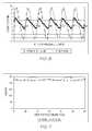
- FIG. 6is a graph comparing the cogging torque as a function of rotor position for a concentrated winding machine having magnetic wedges in accordance with the example embodiment and for a conventional concentrated winding machine that has teeth tips like the conventional design illustrated in FIG. 5 .
- FIG. 7is a graph comparing the machine torque as a function of rotor position for a 24-16 fixed-tooth stator concentrated winding machine having magnetic wedges in accordance with the example embodiment and for a conventional 24-16 fixed-tooth stator concentrated winding machine that has teeth tips like the conventional design illustrated in FIG. 5 .
- FIG. 8is a sectional diagram that further illustrates a magnetic stator slot wedge and its relationship to the stator teeth and the rotor in accordance with an example embodiment.
- FIG. 9is a graph that compares the natural frequency of a stator as a function of mode number, for a stator fabricated with magnetic wedges in accordance with the example embodiment and for a conventional fixed-tooth segmented stator without magnetic wedges.
- FIG. 10is a graph that illustrates the core loss as a function of rotor position for an electrical machine having a conventional stator design and an electrical machine having a stator with magnetic wedges in accordance with the example embodiment.
- FIG. 11is a flowchart illustrating some processes included in a method of fabricating a concentrated winding machine according to an example embodiment.
- FIG. 12is a flowchart illustrating some processes included in a method for improving the characteristics of a fixed-tooth stator having stator teeth that define stator slots and slot openings according to an example embodiment.
- FIG. 13is a flowchart illustrating some processes included in a method according to an example embodiment.
- FIG. 4is a sectional diagram illustrating the arrangement of the stator slots and rotor poles in a portion 800 of a concentrated winding machine in accordance with an example embodiment.
- the portion 800 illustrated in FIG. 4has a periodicity of 8, that is, only 1 ⁇ 8 th of the complete geometry is shown in the diagram.
- fixed-tooth stator segments 810each have a stator tooth 820 , where stator slots 830 are defined between adjacent stator teeth 820 . Also shown in portion 800 are a rotor 840 , north rotor poles 850 , and south rotor poles 860 . In total, there are twenty-four stator slots 830 and sixteen rotor poles 850 , 860 , resulting in a slot-to-pole ratio of 1.5.
- the geometry of FIG. 4may be referred to as a 24-16 geometry. It should be emphasized that the 24-16 geometry is merely an example; alternative embodiments may have different numbers of slots and poles that result in a different slot-to-pole ratio.
- the stator segments 810together form an annular stator yoke and the stator teeth 820 extend from an edge of the annular stator yoke to define stator slots 830 between adjacent stator teeth and slot openings at distal ends of the stator teeth.
- the concentrated winding machinefurther includes three phase windings A, B, C that form coils around the stator teeth 820 and that occupy a portion of the stator slots 830 .
- each of the windings A, B, Chas a positive coil-side and a negative coil-side, the negative coil-side indicated by the prime symbol (e.g., the negative coil-side of the phase A winding in indicated by A′).
- FIG. 8illustrates a common configuration where the stator segments 810 surround a rotor 840 that rotates on a shaft (not shown).
- the inventive aspects of the example embodimentmay also be applied to so-called “inside-out” designs where the rotor rotates around the stator.
- FIG. 5is a diagram that illustrates the winding distribution for the 24-16 geometry of FIG. 4 .
- six numbered slotsare illustrated, representing one fourth of the complete 24-16 geometry.
- there are two windings in each of the stator slots 830where the phase of each winding is referred to with the letters A, B, C, and where the positive and negative coil-sides of each winding is indicated by the absence or presence of the “prime” symbol. That is, A′, B′, and C′ are all indicative of the negative coil-side.
- the stator 800 of FIG. 4has double-layer concentrated windings.
- the bottom half of FIG. 5illustrates the relationship of the rotor poles 850 , 860 of FIG.
- phase windings A, B, C of FIG. 5the relative magnitude and phase difference among the phase windings is as follows: Phase A: [0.866, ⁇ 30], Phase B: [0.866, 90], Phase C: [0.866, 210].
- the cogging frequency in the arrangement illustrated in FIG. 4 and FIG. 5is 48 times the rotor mechanical frequency. Of course, other embodiments may exhibit different magnitudes, phases, and cogging frequencies.
- the portion 800further includes magnetic wedges 870 joined to the distal ends of adjacent stator teeth 820 to close the slot openings of the stator slots 830 .
- the example embodimentlacks teeth tips 515 or 715 .
- the presence of teeth tips 515means that the individual stator segments 510 are separately bobbin-wrapped with a plastic bobbin to form the coils, as was described above.
- stator segments 810may be assembled to form the stator and thereafter the coils, which have been wound separately, may be slipped over the end of the stator teeth 820 along with a paper slot liner.
- the magnetic wedges 870may then be joined to the stator teeth 820 after the coils and slot liners have been arranged on the stator teeth 820 .
- the presence of the magnetic wedges 870also improves physical characteristics of the electrical machine. This is explained in further detail in the following paragraphs, which contain terms such as slotting effect, noise, vibration, cogging torque, torque ripple, leakage flux, eddy current, core loss, and spin loss. These terms refer to undesirable physical phenomena that may be present, in varying degrees, in electrical machines. Other terms such as reluctance, permeability, and rotor skew are also used. Since the meanings associated with these terms are well-known to those of skill in the art, a complete and thorough description of these terms is omitted for the sake of brevity, and cursory descriptions of these terms may instead appear.
- slotting effectarises due to the presence of slots and slot openings in the stator, such as the slots 520 and slot openings 505 of FIG. 1 , which have a lower magnetic permeability relative to the stator teeth material, which is typically iron.
- the example embodiment illustrated in FIG. 4does not have teeth tips, which allows the winding to be wound outside and then slid onto the teeth.
- the elimination of the teeth tipsmeans the slot openings of the slots 830 ( FIG. 4 ) are wider than the slot openings 505 for the conventional stator of FIG. 1 .
- Increasing the width of the slot openinggenerally results in an increased slotting effect.
- Cogging torqueis produced from the physical structure of the machine, e.g., the magnetic attraction between the rotor-mounted magnets and the stator teeth. Cogging torque is an undesirable effect that contributes to torque ripple, vibration, and noise in the machine.
- the cogging torquecan be physically felt if one attempts to manually turn the rotor of a small machine within a stator—in some positions the rotor will turn relatively easily, while in others there will be a noticeably increased resistance to the applied torque.
- torque rippleis produced from the harmonic content of the current and voltage waveforms in the machine. Torque ripple can be produced by the same slotting effect but at the presence of the winding current. The latter effect usually the major source of torque ripple in most machines.
- the magnetic wedges 870are positioned across the slot opening to reduce the slotting effect. That is, the permeability of the selected wedge material is preferably high enough such that the reluctance of the magnetic field near the slot opening is reduced, thus lowering the slotting effect.
- FIG. 6is a graph illustrating the cogging torque as a function of rotor position for a 24-16 concentrated winding machine having magnetic wedges in accordance with the example embodiment and for a conventional 24-16 stator concentrated winding machine that has teeth tips, like the conventional design illustrated in FIG. 1 .
- the peak-to-peak cogging torqueis reduced from 18 Newton meters (Nm) to 5 Nm after the introduction of the magnetic wedges.
- FIG. 7is a graph illustrating the machine torque as a function of rotor position for a 24-16 concentrated winding machine having magnetic wedges in accordance with the example embodiment and for a conventional 24-16 concentrated winding machine that has teeth tips and no magnetic wedges, like the conventional design with teeth tips 515 illustrated in FIG. 1 .
- the average torqueis 232 Nm while the peak-to-peak torque ripple is 24 Nm, or about 10.3% of the average torque.
- the average torque of the geometry with the magnetic wedgeis 223 Nm, a reduction of roughly 4% compared to the conventional design, while the peak-to-peak torque ripple is reduced to only 8.5 Nm, or about 3.8% of the average torque.
- the average torque produced by the example embodimentis slightly less compared to the conventional design, there is a significant improvement in the torque ripple.
- FIG. 7is also illustrative of an additional advantage of the magnetic wedges 870 , which is related to noise. Noise performance is also an important design consideration for electrical motors.
- the 24-16 geometry of FIG. 4has a slot-to-pole ratio of 1.5.
- this specific ratio of stator slots to rotor polesensures a favorable radial force distribution. Since the radial force is a major source of noise, the ratio of 1.5 is also known as one that reduces machine noise, but it is unfortunately also a ratio that is associated with an increased torque ripple.
- a conventional method of reducing the unwanted torque rippleis to skew the rotor. However, rotor skewing increases the manufacturing cost and also reduces the machine torque by roughly 4% or greater. It should be noted that in FIG. 7 , the significant improvement to the torque ripple achieved by the example embodiment is attainable without any skewing of the rotor, and the reduction in the average torque is less than what is typically achieved through conventional rotor skewing.
- the magnetic wedges 870significantly reduce the repercussions of the slotting effect by reducing both the cogging torque and the torque ripple.
- the permeability of the magnetic material used in the magnetic wedges 870is also preferably low enough to reduce the amount of leakage flux. That is, the permeability of the selected wedge material should also be lower than the permeability of the stator and rotor material in order to reduce the amount of leakage flux that would otherwise lower the machine torque.
- the permeability of the magnetic wedges 870is carefully selected such that it is high enough to reduce the slotting effect, but low enough to also reduce the amount of leakage flux.
- Powdered metal core type materialsuch as Somoloy 500 manufactured by Hoganas AB of Hoganas, Sweden is one possible choice for the material of the magnetic wedge 870 .
- FIG. 8is a sectional diagram that further illustrates a magnetic stator slot wedge 1200 and its relationship to the stator teeth 1210 and the rotor 1205 in accordance with an example embodiment.
- the magnetic stator slot wedge 1200is shown in position across the slot opening of the stator slot 1215 , between two adjacent stator teeth 1210 .
- the stator slot wedge 1200is disposed at a distance 1220 from the surface of the rotor 1205 . This distance is typically close to the airgap between the rotor and the stator.
- Two windings 1230 , 1240are also shown occupying the stator slot 1215 .
- Protrusions 1250 , 1270 on the edges of the stator slot wedge 1200correspond to grooves 1260 , 1280 , respectively on the edges of the stator teeth 1210 .
- the grooves 1260 , 1280are used to join the magnetic stator wedge 1200 to the stator teeth 1210 .
- the grooves 1260 , 1280may be cut into the stator teeth 1210 or alternatively, formed at the same time as the stator teeth 1210 (e.g., punched lamination).
- FIG. 8illustrates that according to the example embodiment, the protrusion 1250 and its corresponding groove 1260 are radially offset from the protrusion 1270 and its corresponding groove 1280 .
- the magnetic slot wedge 1200has an asymmetric cross-section about the plane AB that contains the axis of rotation of the rotor and that is also equidistant from the ends of the magnetic slot wedge.
- the protrusion 1250 that engages one of the adjacent stator teeth 1210 and the protrusion 1270 that engages the other one of the adjacent stator teeth 1210is not symmetric about the plane AB.
- the magnetic slot wedge 1200includes two protrusions 1250 , 1270 that are structured to engage the ends of adjacent stator teeth 1210 at different radial positions relative to the axis of rotation of the rotor (not shown) that is contained by the plane AB.
- Each of the stator teeth 1200includes a groove 1260 , 1280 disposed at the end of the stator tooth, where the grooves are structured to engage one of the two protrusions 1250 , 1270 .
- the radial position of the groove 1280 relative to the axis of rotationoverlaps the radial position of the groove 1260 . That is, both the groove 1260 and the groove 1280 are intersected by a single arc that is located at a fixed distance from the axis of rotation.
- the radial position of the grooves 1260 , 1280is such that no single arc located at a fixed distance from the axis of rotation will intersect both of the grooves.
- the grooves 1260 , 1280may be said to be partially radially offset
- the grooves 1260 , 1280can be said to be entirely radially offset.
- Radially offsetting the grooves 1260 , 1280 in the manner described aboveis advantageous because it may be used to reduce the overall narrowing of the stator teeth 1210 in some or all radial positions, thereby preventing any significant reduction in magnetic flux in the stator teeth or torque.
- the grooves 1260 , 1280may not be radially offset at all. Obviously, these embodiments could not reduce the narrowing of the stator teeth which is achieved through the embodiments that use radially offset grooves, but these embodiments would still be effective in preventing a reduction in torque.
- FIG. 9is a graph that illustrates the natural frequency of a stator as a function of mode number, for a fixed-tooth stator fabricated with magnetic wedges in accordance with the example embodiment and for a corresponding conventional fixed-tooth segmented stator without magnetic wedges.
- the inclusion of the stator wedgehas increased the natural frequency of the stator significantly (top line) relative to the conventional stator (bottom line). As a result of the increased stiffness, machine noise and vibration is reduced.
- FIG. 10is a graph of the core loss (in Watts, W) as a function of rotor position for both a conventional fixed tooth stator design and a stator having magnetic wedges in accordance with the example embodiment.
- the induced eddy currents and core losses arising from the rotation of the machinemay collectively be referred to as spin loss.
- FIG. 11is a flowchart illustrating some processes included in a method 1500 of fabricating a concentrated winding machine according to an example embodiment.
- Method 1500begins with process 1510 , with the fabrication of stator segments. Each of the stator segments has at least one stator tooth, but contrary to conventional designs the stator tooth may not have teeth tips.
- process 1520the stator windings for the concentrated winding machine are wound apart from the stator segments, using a bobbin winding method or other method known in the art. In alternative embodiments, process 1520 may occur before process 1510 .
- process 1530the stator windings and a relatively thin paper slot liner are positioned over the stator teeth by sliding the windings and the paper slot liner over the end of the tooth.
- paper insulationmay be wrapped around the stator teeth and the winding formed outside may be slid onto the stator teeth, over the paper slot liner.
- magnetic wedgesare inserted across the slot openings between adjacent stator teeth to close the slot openings and to achieve the advantages discussed in the above paragraphs.
- stator windingsmay be wound apart from the stator teeth and then slid over the ends of the stator teeth along with a relatively thin paper slot liner.
- Thisadvantageously increases the slot fill factor for the stator relative to the conventional method, such as illustrated in FIG. 2 , where a relatively thick plastic slot liner 640 is used.
- An added advantageis that the thinner paper insulation may be used in conjunction with segmented stator construction, which is stronger than the method of inserting stator teeth into a continuous back ring, as was explained above with regard to FIG. 3 .
- concentrated winding machines manufactured in accordance with example embodiments and achieving improved performance in accordance with example embodimentsmay be advantageously incorporated into a variety of electro-mechanical systems as will be apparent to those of skill in the art.
- FIG. 12is a flowchart illustrating some processes included in a method 1600 for improving the characteristics of a fixed-tooth stator having stator teeth that define stator slots and slot openings according to an example embodiment.
- Method 1600begins with process 1610 , which is the formation of radially offset grooves in adjacent stator teeth.
- the groovesare formed proximate to the distal ends of the adjacent stator teeth, but are radially offset from one another. That is, the grooves do not lie at the same distance from a geometric center of the fixed tooth stator. As was explained above, this offset decreases the overall reduction in the width of the stator teeth, which prevents undesirable reductions in flux and torque.
- the slot openingsare closed by inserting magnetic wedges into the grooves, which achieves the advantages that were discussed above.
- FIG. 13is a flowchart illustrating some processes included in a method 1700 according to an example embodiment.
- the methodbegins at process 1710 , which is the fabrication of a fixed-tooth stator that does not allow for relative movement between adjacent stator teeth.
- the stator teethdefine stator slots and slot openings between adjacent stator teeth.
- magnetic wedgesare inserted between adjacent stator teeth to achieve the advantages discussed above.
- process 1710may include assembling the fixed tooth-stator from stator segments, where the stator segments each have at least one stator tooth that is integral to the stator segment. In an example embodiment, process 1710 may include fabricating the stator such that the stator teeth do not have teeth tips.
- process 1720may include inserting magnetic wedges that have protrusions to engage a corresponding groove on each one of the adjacent stator teeth.
- the protrusionsmay be arranged to engage the corresponding groove at different relative positions on each one of the adjacent stator teeth.
- a methodincludes fabricating stator segments having stator teeth that are integral to the stator segment, assembling the stator segments to form a stator that does not allow for relative movement between adjacent stator teeth, the stator teeth forming stator slots between adjacent stator teeth. The method further includes inserting magnetic slot wedges between adjacent stator teeth to close the stator slots.
- fabricating the stator segmentsincludes forming a first groove at a distal end of a first stator tooth and forming a second groove at a distal end of a second stator tooth.
- the first and second groovesmay be arranged such that the first and second grooves are radially offset from one another after the stator segments are assembled.
- inserting magnetic slot wedgesincludes inserting a first magnetic slot wedge having a first protrusion and a second protrusion between the first stator tooth and the second stator tooth.
- the first protrusionengages the first groove and the second protrusion engages the second groove.
- a methodfurther includes wrapping a conductive winding around an object to form coils in the conductive winding, and sliding each of the coils over a distal end of a corresponding one of the stator teeth to position each of the coils around the corresponding one of the stator teeth.
- sliding each of the coilsincludes sliding each of the coils to achieve a concentrated winding configuration where a positive coil-side and a negative coil-side for the conductive winding are disposed adjacent to one another.
- the methodfurther includes positioning a paper slot liner over the distal end of the corresponding one of the stator teeth, the paper slot liner insulating each of the coils from the corresponding one of the stator teeth.
- a methodincludes fabricating a magnetic slot wedge that is adapted to be joined to a first stator tooth and a second stator tooth.
- the first and second stator toothmay be part of a fixed-tooth stator that does not allow relative movement between the first stator tooth and the second stator tooth.
- fabricating the magnetic slot wedgeincludes forming a first protrusion on the magnetic slot wedge, the first protrusion adapted to engage a first groove on the first stator tooth. Fabricating the magnetic slot wedge may further include forming a second protrusion on the magnetic slot wedge, the second protrusion adapted to engage a second groove on the second stator tooth. According to an example embodiment, the first protrusion and the second protrusion are arranged such that, when the first protrusion and second protrusion are engaging the first and second grooves, respectively, the first protrusion and the second protrusion are radially offset from one another relative to a geometric center of the fixed-tooth stator. According to an example embodiment, fabricating the magnetic slot wedge includes fabricating the magnetic slot wedge using a material having a permeability that is less than a permeability of a material used to fabricate the first stator tooth and the second stator tooth.
- the methodmay further include forming the first groove in the first stator tooth, and forming the second groove in the second stator tooth.
- forming the first and second groovesincludes cutting the first and second grooves into the first and second stator teeth.
- the magnetic slot wedgeis adapted to close a stator slot between the first stator tooth and the second stator tooth in the fixed-tooth stator.
- a methodincludes fabricating a fixed-tooth stator that has stator teeth with distal ends, the stator teeth defining stator slots and slot openings between adjacent stator teeth, the fixed-tooth stator not allowing for relative movement between adjacent stator teeth. The method further includes inserting magnetic wedges between adjacent stator teeth to close the slot openings.
- fabricating the fixed-tooth statorincludes assembling the fixed-tooth stator from stator segments, the stator segments each having at least one stator tooth, the at least one stator tooth integral to the stator segment. According to an example embodiment, fabricating the fixed-tooth stator further comprises fabricating the fixed-tooth stator such that the stator teeth do not have teeth tips. According to an example embodiment, fabricating the fixed-tooth stator further includes positioning coils around the stator teeth by sliding the coils over the distal ends of the stator teeth. According to an example embodiment, positioning coils around the stator teeth includes positioning the coils in a concentrated winding pattern such that a positive coil-side of a winding and a negative coil-side of the winding are arranged adjacent to each other.
- fabricating the fixed-tooth statorfurther includes positioning paper slot liners around the stator teeth by sliding the paper slot liners over the distal ends of the stator teeth.
- inserting magnetic wedges between adjacent stator teethincludes inserting magnetic wedges that have protrusions. Each protrusion may be arranged to engage a corresponding groove on each one of the adjacent stator teeth, and the protrusions may be arranged to engage the corresponding groove at different relative positions on each one of the adjacent stator teeth.
Landscapes
- Engineering & Computer Science (AREA)
- Power Engineering (AREA)
- Insulation, Fastening Of Motor, Generator Windings (AREA)
- Iron Core Of Rotating Electric Machines (AREA)
Abstract
Description
Claims (15)
Priority Applications (3)
| Application Number | Priority Date | Filing Date | Title |
|---|---|---|---|
| US11/940,407US8129880B2 (en) | 2007-11-15 | 2007-11-15 | Concentrated winding machine with magnetic slot wedges |
| DE102008056934ADE102008056934A1 (en) | 2007-11-15 | 2008-11-12 | Machine with concentrated windings with magnetic slot wedges |
| CN200810178270.6ACN101436797B (en) | 2007-11-15 | 2008-11-17 | Concentrated winding machine with magnetic slot wedges |
Applications Claiming Priority (1)
| Application Number | Priority Date | Filing Date | Title |
|---|---|---|---|
| US11/940,407US8129880B2 (en) | 2007-11-15 | 2007-11-15 | Concentrated winding machine with magnetic slot wedges |
Publications (2)
| Publication Number | Publication Date |
|---|---|
| US20090127942A1 US20090127942A1 (en) | 2009-05-21 |
| US8129880B2true US8129880B2 (en) | 2012-03-06 |
Family
ID=40641147
Family Applications (1)
| Application Number | Title | Priority Date | Filing Date |
|---|---|---|---|
| US11/940,407Expired - Fee RelatedUS8129880B2 (en) | 2007-11-15 | 2007-11-15 | Concentrated winding machine with magnetic slot wedges |
Country Status (3)
| Country | Link |
|---|---|
| US (1) | US8129880B2 (en) |
| CN (1) | CN101436797B (en) |
| DE (1) | DE102008056934A1 (en) |
Cited By (11)
| Publication number | Priority date | Publication date | Assignee | Title |
|---|---|---|---|---|
| WO2014074423A2 (en) | 2012-11-06 | 2014-05-15 | Russel Marvin | Compact permanent magnet machine construction |
| WO2014165440A1 (en) | 2013-04-03 | 2014-10-09 | Lcdrives Corp. | Liquid cooled stator for high efficiency machine |
| US8907541B2 (en) | 2012-09-25 | 2014-12-09 | Remy Technologies, L.L.C. | Slot liner for electro-dynamic machine |
| US9312730B2 (en) | 2012-10-11 | 2016-04-12 | Whirlpool Corporation | Stator with a polymeric casing for an electric motor of a washing machine and method of manufacturing the same |
| US9979248B2 (en) | 2015-06-29 | 2018-05-22 | General Electric Company | Short circuit fault tolerant permanent magnet machine |
| FR3089712A1 (en) | 2018-12-11 | 2020-06-12 | IFP Energies Nouvelles | Electric machine stator with a crown formed by a plurality of stator segments |
| US10707716B2 (en) | 2017-11-20 | 2020-07-07 | Borgwarner Inc. | Stator core and stator slot closer |
| US20210218294A1 (en)* | 2018-06-07 | 2021-07-15 | Moteurs Leroy-Somer | Stator for a rotating electrical machine |
| US11081924B2 (en) | 2018-06-04 | 2021-08-03 | Honeywell International Inc. | Method and apparatus to reduce losses in a compact high speed generator |
| US11133718B2 (en) | 2018-07-11 | 2021-09-28 | Ford Global Technologies, Llc | Electric machine with slot closers |
| US11949284B2 (en) | 2018-06-07 | 2024-04-02 | Moteurs Leroy-Somer | Stator for a rotating electrical machine |
Families Citing this family (22)
| Publication number | Priority date | Publication date | Assignee | Title |
|---|---|---|---|---|
| JP2012507983A (en) | 2008-11-03 | 2012-03-29 | モーター エクセレンス, エルエルシー | Multiphase transverse and / or commutated flux system |
| CN101895159B (en)* | 2009-05-21 | 2015-06-03 | 巨铠实业股份有限公司 | Motor unit |
| DE102009034791A1 (en)* | 2009-07-25 | 2011-01-27 | Robert Bosch Gmbh | Extruded iron core for an electric motor |
| CN102124632B (en)* | 2009-09-11 | 2013-01-23 | 配天(安徽)电子技术有限公司 | Square-wave three-phase brushless permanent magnet DC motor with large and small teeth structure and its assembly method |
| WO2011029234A1 (en)* | 2009-09-11 | 2011-03-17 | 深圳航天科技创新研究院 | Large-diameter type square-wave three-phase brushless permanent magnet direct current motor and assembling method thereof |
| WO2011115634A1 (en) | 2010-03-15 | 2011-09-22 | Motor Excellence Llc | Transverse and/or commutated flux systems having phase offset |
| EP2548288A1 (en) | 2010-03-15 | 2013-01-23 | Motor Excellence, LLC | Transverse and/or commutated flux systems configured to provide reduced flux leakage, hysteresis loss reduction, and phase matching |
| US8395291B2 (en)* | 2010-03-15 | 2013-03-12 | Electric Torque Machines, Inc. | Transverse and/or commutated flux systems for electric bicycles |
| CN102280946A (en)* | 2010-06-09 | 2011-12-14 | 王金山 | Highly energy-saving combined stator motor |
| US8405275B2 (en) | 2010-11-17 | 2013-03-26 | Electric Torque Machines, Inc. | Transverse and/or commutated flux systems having segmented stator laminations |
| US8854171B2 (en) | 2010-11-17 | 2014-10-07 | Electric Torque Machines Inc. | Transverse and/or commutated flux system coil concepts |
| US8952590B2 (en) | 2010-11-17 | 2015-02-10 | Electric Torque Machines Inc | Transverse and/or commutated flux systems having laminated and powdered metal portions |
| AT12977U1 (en)* | 2011-06-10 | 2013-03-15 | Seewald Hansjoerg Ing | CLOSING WEDGE |
| US20130057107A1 (en)* | 2011-09-02 | 2013-03-07 | Steven Stretz | Permanent magnet motors and methods of assembling the same |
| JP5742804B2 (en)* | 2012-09-06 | 2015-07-01 | トヨタ自動車株式会社 | Rotating electric machine rotor and rotating electric machine |
| KR20180093872A (en)* | 2015-08-11 | 2018-08-22 | 제네시스 로보틱스 엘엘피 | Electric machine |
| JP6829173B2 (en)* | 2017-09-21 | 2021-02-10 | 株式会社東芝 | Magnetic wedge and rotary electric machine |
| CN109599965A (en)* | 2018-12-25 | 2019-04-09 | 合肥旭弘塑胶制品有限公司 | A kind of plastic stator of plastic packaging motor |
| ES2914811T3 (en)* | 2019-05-27 | 2022-06-16 | Magnax Bv | Stator for an axial flow machine |
| EP3822467B1 (en)* | 2019-11-12 | 2024-05-22 | G+L Innotec GmbH | Air gap motor, in particular for a turbocharger |
| CN114400855B (en)* | 2022-01-24 | 2023-06-16 | 沈阳工程学院 | Stator-rotor double-module permanent magnet synchronous motor |
| CN119813612B (en)* | 2024-12-17 | 2025-09-23 | 扬州宝飞优斯特振动器制造有限公司 | A wire-embedded stator with intelligent temperature control and heating function |
Citations (72)
| Publication number | Priority date | Publication date | Assignee | Title |
|---|---|---|---|---|
| US2636137A (en)* | 1948-01-21 | 1953-04-21 | Smith Corp A O | Dynamoelectric apparatus and method of making the same |
| US2710931A (en)* | 1951-08-09 | 1955-06-14 | Ilse Ott | Slot closure wedges for electric machines |
| US3035195A (en)* | 1957-04-08 | 1962-05-15 | Elektro Motoren A G | Structural member for conducting a magnetic flux |
| US3845339A (en) | 1971-09-01 | 1974-10-29 | Papst Motoren Kg | Permanent magnet rotor electric motor |
| US3866070A (en)* | 1971-12-27 | 1975-02-11 | Asea Ab | Turbo-generator of the radial slot type |
| US3952406A (en)* | 1975-03-05 | 1976-04-27 | Allmanna Svenska Elektriska Aktiebolaget | Method of securing the rotor winding of a turbo-generator rotor |
| US3999092A (en) | 1974-04-04 | 1976-12-21 | Canadian General Electric Company Limited | Permanent magnet synchronous dynamoelectric machine |
| US4149101A (en)* | 1977-05-12 | 1979-04-10 | Lesokhin Albert Z | Arrangement for locking slot wedges retaining electric windings |
| JPS55144747A (en)* | 1979-04-26 | 1980-11-11 | Hitachi Ltd | Rotor for rotary machine |
| JPS5635647A (en)* | 1979-08-31 | 1981-04-08 | Toshiba Corp | Rotor for electric rotary machine |
| US4264835A (en) | 1977-09-02 | 1981-04-28 | Siemens Aktiengesellschaft | Slot closure for the semi-closed slots of an electric machine stator |
| US4267719A (en)* | 1977-09-19 | 1981-05-19 | Industra Products, Inc. | Apparatus for assembling dynamoelectric machine stators |
| JPS56136148A (en)* | 1980-03-26 | 1981-10-24 | Fanuc Ltd | Wedges for noise-proof of dc electrical machine |
| JPS56145741A (en)* | 1980-04-15 | 1981-11-12 | Fanuc Ltd | Wedge for preventing noise of dc electric machine |
| US4319152A (en) | 1976-07-12 | 1982-03-09 | Gils Adrianus W Van | Laminated winding for electric machines |
| EP0068727A1 (en)* | 1981-06-29 | 1983-01-05 | General Electric Company | Method and means for retaining coils in dynamoelectric machines |
| US4374337A (en)* | 1980-02-12 | 1983-02-15 | Fujitsu Fanuc Limited | Direct current motor having E-shaped interpoles |
| US4427910A (en)* | 1982-03-01 | 1984-01-24 | General Electric Company | Magnetic slot wedge with low average permeability and high mechanical strength |
| JPS59136040A (en)* | 1983-01-21 | 1984-08-04 | Mitsubishi Electric Corp | Magnetic “wedge” in rotating electrical machines |
| JPS6051427A (en)* | 1983-08-26 | 1985-03-22 | Hitachi Ltd | Magnetic wedge of rotating electric machine |
| US4510409A (en) | 1982-09-28 | 1985-04-09 | Nippondenso Co., Ltd. | Heat insulation and heat dissipation construction for flat electric rotary machine |
| FR2559967A1 (en)* | 1984-02-17 | 1985-08-23 | Sarelem | Skew notch wedge. |
| GB2159342A (en) | 1984-05-22 | 1985-11-27 | Dso Elprom | A rotor for an electrical machine |
| US4578610A (en) | 1978-06-12 | 1986-03-25 | General Electric Company | Synchronous disk motor with amorphous metal stator and permanent magnet rotor and flywheel |
| US4584497A (en)* | 1984-09-28 | 1986-04-22 | General Electric Company | Beam support for bar windings of large electric generator |
| US4644202A (en) | 1985-04-15 | 1987-02-17 | Rockwell International Corporation | Sealed and balanced motor and fluid pump system |
| US4719377A (en) | 1984-09-29 | 1988-01-12 | Kabushiki Kaisha Toshiba | Armature annular core |
| US4788464A (en) | 1986-10-29 | 1988-11-29 | Sony Corporation | Disc drive with integral spindle yoke |
| US4866324A (en) | 1987-04-28 | 1989-09-12 | Canon Kabushiki Kaisha | Brushless motor |
| US5093597A (en) | 1990-10-01 | 1992-03-03 | Westinghouse Electric Corp. | Brushless exciter saturable reactor diode snubber |
| EP0533359A2 (en) | 1991-09-18 | 1993-03-24 | Newport News Shipbuilding And Dry Dock Company | Electric propulsion motor for marine vehicles |
| US5272938A (en) | 1992-12-04 | 1993-12-28 | Hsu Chi Hsueh | Flat rim type motor drive mechanism for bicycles |
| JPH07154949A (en)* | 1993-09-30 | 1995-06-16 | Toshiba Corp | Coil and insulator insertion method and insertion device |
| JPH07245896A (en)* | 1994-03-07 | 1995-09-19 | Asmo Co Ltd | Rotary electric machine |
| WO1996038902A1 (en) | 1995-05-31 | 1996-12-05 | The Turbo Genset Company Limited | Rotary electrical machines |
| JPH08340653A (en)* | 1995-06-09 | 1996-12-24 | Mitsubishi Electric Corp | Rotating machine rotor |
| GB2303499A (en)* | 1995-07-20 | 1997-02-19 | Still Gmbh | Electric machine slot wedge |
| US5744896A (en) | 1996-05-21 | 1998-04-28 | Visual Computing Systems Corp. | Interlocking segmented coil array |
| US5753991A (en) | 1994-12-02 | 1998-05-19 | Hydro-Quebec | Multiphase brushless AC electric machine |
| US5831365A (en) | 1995-06-30 | 1998-11-03 | Kaman Electromagnetics Corporation | Detachable magnet carrier for permanent magnet motor |
| DE29816561U1 (en) | 1998-09-15 | 1998-12-17 | Lin, Shou-Mei, Taipeh/T'ai-pei | Double-sided brushless DC motor with non-ferrous core and axial magnetic field of the permanent magnet type |
| US5866959A (en)* | 1994-05-24 | 1999-02-02 | Gec Alsthom Limited | Cooling arrangements for rotating electrical machines |
| US5925947A (en) | 1995-11-27 | 1999-07-20 | Hitachi, Ltd. | Totally-enclosed type motor |
| US6234767B1 (en) | 1997-10-01 | 2001-05-22 | Denyo Co., Lmtd. | Rotor having permanent magnet and mechanism for cooling the same |
| US6331745B2 (en) | 1999-11-22 | 2001-12-18 | General Electric Company | Adjustable generator stator slot wedge system |
| US20020074871A1 (en)* | 2000-12-14 | 2002-06-20 | Toshio Kikuchi | Rotating electric machine |
| US20020074889A1 (en)* | 2000-12-14 | 2002-06-20 | Toshio Kikuchi | Rotating electric machine and method of manufacture therefor |
| US6441530B1 (en) | 2000-12-01 | 2002-08-27 | Petersen Technology Corporation | D.C. PM motor with a stator core assembly formed of pressure shaped processed ferromagnetic particles |
| US6445105B1 (en) | 1999-04-06 | 2002-09-03 | General Electric Company | Axial flux machine and method of fabrication |
| US20020130581A1 (en)* | 1999-06-29 | 2002-09-19 | Sanyo Electric Co., Ltd. | Brushless DC motor and refrigerant compressor employing the motor |
| US6472789B1 (en) | 1998-10-20 | 2002-10-29 | Valeo Equipement Electriques Moteur | Electric rotary machine with novel rotor excitation arrangement by permanent magnets |
| US20020175589A1 (en)* | 2001-05-28 | 2002-11-28 | Mitsubishi Denki Kabushiki Kaisha | Automotive alternator |
| DE10152151A1 (en) | 2001-10-25 | 2003-05-15 | Buhler Motor Gmbh | Permanent magnet rotor for electric motor has permanent magnet ring consisting of compressed, polymer-bound rare earth magnets mounted on plastic mounting produced by injection molding around ring |
| US20030132584A1 (en) | 2001-12-07 | 2003-07-17 | Borroni-Bird Christopher E. | Wheel module |
| US20030193260A1 (en)* | 2002-04-16 | 2003-10-16 | Reiter Frederick B. | Composite power metal stator sleeve |
| US6674201B2 (en) | 1999-12-23 | 2004-01-06 | Data Storage Institute | Spindle motor with an aerodynamic and hydrodynamic bearing assembly |
| US6703742B1 (en) | 1998-12-15 | 2004-03-09 | Adam K. Brandley | Electric motor with rotor being a drive wheel |
| US6710494B2 (en) | 2000-03-02 | 2004-03-23 | Motorenfabrik Hatz Gmbh & Co. Kg | Power generating installation that comprises a generator and a reciprocating internal combustion engine as drive |
| US6720688B1 (en) | 1999-02-12 | 2004-04-13 | Helmut Schiller | Electric machine |
| US6727632B2 (en) | 2001-11-27 | 2004-04-27 | Denso Corporation | Flat rotary electric machine |
| US6756716B2 (en) | 2000-09-12 | 2004-06-29 | Robert Bosch Gmbh | Insulation element and method for introducing winding elements into grooves on an armature |
| US6768932B2 (en) | 2001-12-07 | 2004-07-27 | General Motors Corporation | Wheel motor system |
| US20040155548A1 (en) | 2001-05-08 | 2004-08-12 | Rasmussen Peter Omand | Transverse flux machine with stator made of e-shaped laminates |
| US6830117B2 (en) | 2001-08-23 | 2004-12-14 | General Motors Corporation | Vehicle chassis having systems responsive to non-mechanical control signals |
| US20050004492A1 (en) | 1998-03-03 | 2005-01-06 | Senorx, Inc. | Breast biopsy system and methods |
| US6844653B2 (en) | 2003-03-31 | 2005-01-18 | Valeo Electrical Systems, Inc. | Stator design for permanent magnet motor with combination slot wedge and tooth locator |
| US6844656B1 (en) | 1999-02-10 | 2005-01-18 | Neg Micon Control Systems A/S | Electric multipole motor/generator with axial magnetic flux |
| US20050035678A1 (en)* | 2003-08-11 | 2005-02-17 | Ward Terence G. | Axial flux motor mass reduction with improved cooling |
| JP2005192339A (en)* | 2003-12-25 | 2005-07-14 | Nissan Motor Co Ltd | Electric motor stator structure and electric motor stator manufacturing method |
| US6924574B2 (en) | 2003-05-30 | 2005-08-02 | Wisconsin Alumni Research Foundation | Dual-rotor, radial-flux, toroidally-wound, permanent-magnet machine |
| US20050212379A1 (en)* | 2004-03-23 | 2005-09-29 | General Electric Company | Module winding system for electrical machines and methods of electrical connection |
| US7262536B2 (en) | 2003-08-11 | 2007-08-28 | General Motors Corporation | Gearless wheel motor drive system |
Family Cites Families (1)
| Publication number | Priority date | Publication date | Assignee | Title |
|---|---|---|---|---|
| CN2274387Y (en)* | 1996-07-30 | 1998-02-11 | 丽钢工业股份有限公司 | Motor stator core |
- 2007
- 2007-11-15USUS11/940,407patent/US8129880B2/ennot_activeExpired - Fee Related
- 2008
- 2008-11-12DEDE102008056934Apatent/DE102008056934A1/ennot_activeWithdrawn
- 2008-11-17CNCN200810178270.6Apatent/CN101436797B/ennot_activeExpired - Fee Related
Patent Citations (80)
| Publication number | Priority date | Publication date | Assignee | Title |
|---|---|---|---|---|
| US2636137A (en)* | 1948-01-21 | 1953-04-21 | Smith Corp A O | Dynamoelectric apparatus and method of making the same |
| US2710931A (en)* | 1951-08-09 | 1955-06-14 | Ilse Ott | Slot closure wedges for electric machines |
| US3035195A (en)* | 1957-04-08 | 1962-05-15 | Elektro Motoren A G | Structural member for conducting a magnetic flux |
| US3845339A (en) | 1971-09-01 | 1974-10-29 | Papst Motoren Kg | Permanent magnet rotor electric motor |
| US3866070A (en)* | 1971-12-27 | 1975-02-11 | Asea Ab | Turbo-generator of the radial slot type |
| US3999092A (en) | 1974-04-04 | 1976-12-21 | Canadian General Electric Company Limited | Permanent magnet synchronous dynamoelectric machine |
| US3952406A (en)* | 1975-03-05 | 1976-04-27 | Allmanna Svenska Elektriska Aktiebolaget | Method of securing the rotor winding of a turbo-generator rotor |
| US4319152A (en) | 1976-07-12 | 1982-03-09 | Gils Adrianus W Van | Laminated winding for electric machines |
| US4149101A (en)* | 1977-05-12 | 1979-04-10 | Lesokhin Albert Z | Arrangement for locking slot wedges retaining electric windings |
| US4264835A (en) | 1977-09-02 | 1981-04-28 | Siemens Aktiengesellschaft | Slot closure for the semi-closed slots of an electric machine stator |
| US4267719A (en)* | 1977-09-19 | 1981-05-19 | Industra Products, Inc. | Apparatus for assembling dynamoelectric machine stators |
| US4578610A (en) | 1978-06-12 | 1986-03-25 | General Electric Company | Synchronous disk motor with amorphous metal stator and permanent magnet rotor and flywheel |
| JPS55144747A (en)* | 1979-04-26 | 1980-11-11 | Hitachi Ltd | Rotor for rotary machine |
| JPS5635647A (en)* | 1979-08-31 | 1981-04-08 | Toshiba Corp | Rotor for electric rotary machine |
| US4374337A (en)* | 1980-02-12 | 1983-02-15 | Fujitsu Fanuc Limited | Direct current motor having E-shaped interpoles |
| JPS56136148A (en)* | 1980-03-26 | 1981-10-24 | Fanuc Ltd | Wedges for noise-proof of dc electrical machine |
| JPS56145741A (en)* | 1980-04-15 | 1981-11-12 | Fanuc Ltd | Wedge for preventing noise of dc electric machine |
| EP0068727A1 (en)* | 1981-06-29 | 1983-01-05 | General Electric Company | Method and means for retaining coils in dynamoelectric machines |
| US4427910A (en)* | 1982-03-01 | 1984-01-24 | General Electric Company | Magnetic slot wedge with low average permeability and high mechanical strength |
| US4510409A (en) | 1982-09-28 | 1985-04-09 | Nippondenso Co., Ltd. | Heat insulation and heat dissipation construction for flat electric rotary machine |
| JPS59136040A (en)* | 1983-01-21 | 1984-08-04 | Mitsubishi Electric Corp | Magnetic “wedge” in rotating electrical machines |
| JPS6051427A (en)* | 1983-08-26 | 1985-03-22 | Hitachi Ltd | Magnetic wedge of rotating electric machine |
| FR2559967A1 (en)* | 1984-02-17 | 1985-08-23 | Sarelem | Skew notch wedge. |
| GB2159342A (en) | 1984-05-22 | 1985-11-27 | Dso Elprom | A rotor for an electrical machine |
| DE3517883A1 (en) | 1984-05-22 | 1985-11-28 | DSO "Elprom", Sofia/Sofija | ROTOR OF AN ELECTRICAL MACHINE |
| US4584497A (en)* | 1984-09-28 | 1986-04-22 | General Electric Company | Beam support for bar windings of large electric generator |
| US4719377A (en) | 1984-09-29 | 1988-01-12 | Kabushiki Kaisha Toshiba | Armature annular core |
| US4644202A (en) | 1985-04-15 | 1987-02-17 | Rockwell International Corporation | Sealed and balanced motor and fluid pump system |
| US4788464A (en) | 1986-10-29 | 1988-11-29 | Sony Corporation | Disc drive with integral spindle yoke |
| US4866324A (en) | 1987-04-28 | 1989-09-12 | Canon Kabushiki Kaisha | Brushless motor |
| US5093597A (en) | 1990-10-01 | 1992-03-03 | Westinghouse Electric Corp. | Brushless exciter saturable reactor diode snubber |
| EP0533359A2 (en) | 1991-09-18 | 1993-03-24 | Newport News Shipbuilding And Dry Dock Company | Electric propulsion motor for marine vehicles |
| US5272938A (en) | 1992-12-04 | 1993-12-28 | Hsu Chi Hsueh | Flat rim type motor drive mechanism for bicycles |
| JPH07154949A (en)* | 1993-09-30 | 1995-06-16 | Toshiba Corp | Coil and insulator insertion method and insertion device |
| JPH07245896A (en)* | 1994-03-07 | 1995-09-19 | Asmo Co Ltd | Rotary electric machine |
| US5866959A (en)* | 1994-05-24 | 1999-02-02 | Gec Alsthom Limited | Cooling arrangements for rotating electrical machines |
| US5753991A (en) | 1994-12-02 | 1998-05-19 | Hydro-Quebec | Multiphase brushless AC electric machine |
| WO1996038902A1 (en) | 1995-05-31 | 1996-12-05 | The Turbo Genset Company Limited | Rotary electrical machines |
| DE69610423T2 (en) | 1995-05-31 | 2001-05-10 | The Turbo Genset Co. Ltd., London | ELECTRIC LATHE |
| JPH08340653A (en)* | 1995-06-09 | 1996-12-24 | Mitsubishi Electric Corp | Rotating machine rotor |
| US5831365A (en) | 1995-06-30 | 1998-11-03 | Kaman Electromagnetics Corporation | Detachable magnet carrier for permanent magnet motor |
| DE69604537T2 (en) | 1995-06-30 | 2001-03-01 | Newport News Shipbuilding And Dry Dock Co., Newport News | Removable magnetic carrier for a permanent magnet motor |
| GB2303499A (en)* | 1995-07-20 | 1997-02-19 | Still Gmbh | Electric machine slot wedge |
| US5925947A (en) | 1995-11-27 | 1999-07-20 | Hitachi, Ltd. | Totally-enclosed type motor |
| US5744896A (en) | 1996-05-21 | 1998-04-28 | Visual Computing Systems Corp. | Interlocking segmented coil array |
| DE69825386T2 (en) | 1997-10-01 | 2005-08-18 | Denyo Co., Ltd. | Permanent magnet rotor and cooling device |
| US6234767B1 (en) | 1997-10-01 | 2001-05-22 | Denyo Co., Lmtd. | Rotor having permanent magnet and mechanism for cooling the same |
| US20050004492A1 (en) | 1998-03-03 | 2005-01-06 | Senorx, Inc. | Breast biopsy system and methods |
| DE29816561U1 (en) | 1998-09-15 | 1998-12-17 | Lin, Shou-Mei, Taipeh/T'ai-pei | Double-sided brushless DC motor with non-ferrous core and axial magnetic field of the permanent magnet type |
| US6011337A (en) | 1998-09-15 | 2000-01-04 | Lin; Shou-Mei | Double-sided, non-iron core, brushless, axial magnetic field permanent-magnet type DC motor |
| DE69903187T2 (en) | 1998-10-20 | 2003-06-18 | Valeo Equipements Electriques Moteur, Creteil | ROTATING ELECTRIC MACHINE WITH NEW ARRANGEMENT FOR PERMANENTLY MAGNETIC RUNNERS |
| US6472789B1 (en) | 1998-10-20 | 2002-10-29 | Valeo Equipement Electriques Moteur | Electric rotary machine with novel rotor excitation arrangement by permanent magnets |
| US6703742B1 (en) | 1998-12-15 | 2004-03-09 | Adam K. Brandley | Electric motor with rotor being a drive wheel |
| US6844656B1 (en) | 1999-02-10 | 2005-01-18 | Neg Micon Control Systems A/S | Electric multipole motor/generator with axial magnetic flux |
| US6720688B1 (en) | 1999-02-12 | 2004-04-13 | Helmut Schiller | Electric machine |
| US6445105B1 (en) | 1999-04-06 | 2002-09-03 | General Electric Company | Axial flux machine and method of fabrication |
| US20020130581A1 (en)* | 1999-06-29 | 2002-09-19 | Sanyo Electric Co., Ltd. | Brushless DC motor and refrigerant compressor employing the motor |
| US6331745B2 (en) | 1999-11-22 | 2001-12-18 | General Electric Company | Adjustable generator stator slot wedge system |
| US6674201B2 (en) | 1999-12-23 | 2004-01-06 | Data Storage Institute | Spindle motor with an aerodynamic and hydrodynamic bearing assembly |
| US6710494B2 (en) | 2000-03-02 | 2004-03-23 | Motorenfabrik Hatz Gmbh & Co. Kg | Power generating installation that comprises a generator and a reciprocating internal combustion engine as drive |
| US6756716B2 (en) | 2000-09-12 | 2004-06-29 | Robert Bosch Gmbh | Insulation element and method for introducing winding elements into grooves on an armature |
| US6441530B1 (en) | 2000-12-01 | 2002-08-27 | Petersen Technology Corporation | D.C. PM motor with a stator core assembly formed of pressure shaped processed ferromagnetic particles |
| US20020074871A1 (en)* | 2000-12-14 | 2002-06-20 | Toshio Kikuchi | Rotating electric machine |
| US6700283B2 (en)* | 2000-12-14 | 2004-03-02 | Nissan Motor Co., Ltd. | Rotating electric machine and method of manufacture therefor |
| US20020074889A1 (en)* | 2000-12-14 | 2002-06-20 | Toshio Kikuchi | Rotating electric machine and method of manufacture therefor |
| US20040155548A1 (en) | 2001-05-08 | 2004-08-12 | Rasmussen Peter Omand | Transverse flux machine with stator made of e-shaped laminates |
| US20020175589A1 (en)* | 2001-05-28 | 2002-11-28 | Mitsubishi Denki Kabushiki Kaisha | Automotive alternator |
| US6830117B2 (en) | 2001-08-23 | 2004-12-14 | General Motors Corporation | Vehicle chassis having systems responsive to non-mechanical control signals |
| US20030168925A1 (en) | 2001-10-25 | 2003-09-11 | Georg Bernreuther | Permanent magnet rotor |
| DE10152151A1 (en) | 2001-10-25 | 2003-05-15 | Buhler Motor Gmbh | Permanent magnet rotor for electric motor has permanent magnet ring consisting of compressed, polymer-bound rare earth magnets mounted on plastic mounting produced by injection molding around ring |
| US6727632B2 (en) | 2001-11-27 | 2004-04-27 | Denso Corporation | Flat rotary electric machine |
| US6768932B2 (en) | 2001-12-07 | 2004-07-27 | General Motors Corporation | Wheel motor system |
| US20030132584A1 (en) | 2001-12-07 | 2003-07-17 | Borroni-Bird Christopher E. | Wheel module |
| US20030193260A1 (en)* | 2002-04-16 | 2003-10-16 | Reiter Frederick B. | Composite power metal stator sleeve |
| US6844653B2 (en) | 2003-03-31 | 2005-01-18 | Valeo Electrical Systems, Inc. | Stator design for permanent magnet motor with combination slot wedge and tooth locator |
| US6924574B2 (en) | 2003-05-30 | 2005-08-02 | Wisconsin Alumni Research Foundation | Dual-rotor, radial-flux, toroidally-wound, permanent-magnet machine |
| US20050035678A1 (en)* | 2003-08-11 | 2005-02-17 | Ward Terence G. | Axial flux motor mass reduction with improved cooling |
| US7262536B2 (en) | 2003-08-11 | 2007-08-28 | General Motors Corporation | Gearless wheel motor drive system |
| JP2005192339A (en)* | 2003-12-25 | 2005-07-14 | Nissan Motor Co Ltd | Electric motor stator structure and electric motor stator manufacturing method |
| US20050212379A1 (en)* | 2004-03-23 | 2005-09-29 | General Electric Company | Module winding system for electrical machines and methods of electrical connection |
Non-Patent Citations (32)
| Title |
|---|
| Caricchi et al, "Low-Cost Compact PM Machine for Adjustable-Speed Pump Application," Industry Applications Conference, Thirty-First IAS Annual Meeting, Conference Record of the 1996 IEEE, vol. 1, pp. 464-470. |
| Caricchi et al. "Converter Topology with Load-Neutral Modulation for Trapezoidal-EMF PM Motor Drives" IEEE Transaction on Power Electronics, vol. 9, No. 2 Mar. 1994, 232-239. |
| Caricchi et al. "Prototype of Electric Vehicle Drive with Twin Water-Cooled Wheel Direct Drive Motors" IEEE 1996, 1926-1932. |
| Caricchi et al., "20kW Water-Cooled Prototype of a Buck-Boost Bidirectional DC-DC Converter Topology for Electrical Vehicle Motor Drives," IEEE, 1995, pp. 887-892. |
| Caricchi et al., "A Novel Solid-State-Commutator PM Motor Arrangement for EV Application," IEEE, 1999, pp. 2545-2551. |
| Caricchi et al., "Compact Wheel Direct Drive for EVs," IEEE Industry Applications Magazine, Nov./Dec. 1996, pp. 25-32. |
| Caricchi et al., "Design and Construction of a Wheel-Directly-Coupled Axial-Flux PM Motor Prototype for EVs," IEEE, Jan. 1994, pp. 254-261. |
| Caricchi et al., "Experimental Study of a Bidrectional DC-DC Converter for the DC Link Voltage Control and the Regenerative Braking in PM Motor Drives Devoted to Electrical Vehicles," IEEE, May 1994, pp. 381-386. |
| Caricchi et al., "Experimental Study on Reducing Cogging Torque and Core Power Loss in Axial-Flux Permanent-Magnet Machines with Slotted Winding," IEEE, Jul. 2002, pp. 1295-1302. |
| Caricchi et al., "Experimental Study on Reducing Cogging Torque and No-Load Power Loss in Axial-Flux Permanent-Magnet Machines with Slotted Winding," IEEE, Jun. 2004, pp. 1066-1075. |
| Caricchi et al., "Modular Axial-Flux Permanent-Magnet Motor for Ship Propulsion Drives," IEEE Transactions on Energy Conversion, vol. 14, No. 3, Sep. 1999, pp. 673-679. |
| Caricchi et al., "Multi-Stage Axial-Flux PM Machine for Wheel Direct Drive," Industry Applications Conference, 1995, Thirtieth IAS Annual Meeting, Conference Record of the 1995 IEEE, vol. 1, pp. 679-684. |
| Caricchi et al., "Performance of Coreless-Winding Axial Flux Permanent-Magnet Generator with Power Output at 400 Hz, 3000 r/min," Industry Applications, IEEE, 1998, vol. 34, pp. 1263-1269. |
| Caricchi et al., "Prototype of Innovative Wheel Direct Drive with Water-Cooled Axial-Flux PM Motor for Electric Vehicle Applications," Applied Power Electronics Conference and Exposition, 1996, vol. 2, pp. 764-770. |
| Caricchi et al., Basic Principle and Design Criteria of Axial-Flux PM Machines Having Counter-Rotating Rotors, IEEE 1994, 247-253. |
| Carricchi, F. et al. "Three-Wheeled Electric Maxi-Scooter for Improved Driving Performances in Large Urban Areas," IEEE, Feb. 3, 2003, pp. 1363-1368. |
| Cirani et al., "Analysis of an Innovative Design for an Axial Flux Torus Machine," Division of Electrical Machines and Power Electronics, Royal Institute of Technology, Stockholm, Sweden. |
| Honorati et al., "Lightweight, Compact, Three-Wheel Electric Vehicle for Urban Mobility," IEEE, Jun. 1998, pp. 797-802. |
| Huang, S. et al. "TORUS Concept Machines: Pre-Prototyping Design Assessment for Two Major Topologies," Industry Applications Conference, Thirty-Sixth IAS Annual Meeting, Conference Record of the 2001 IEEE (2001), vol. 3: 1619-1625. |
| Letter dated Dec. 1, 2006 from Raja Saliba at Sughrue Mion, PLLC to Christopher DeVries at General Motors Corporation. |
| Li et al. "Reductions of Cogging Torque in Permanent Magnet Motors" IEEE Transactions on Magnetics Nov., 1988, 2901-2903. |
| Libert, F., et al., "Manufacturing Methods of Stator Cores with Concentrated Windings," Royal Institute of Technology, Department of Electrical Machines and Power Electronics, Sweden, Published: 2006. |
| Magnussen, F. et al., "Winding Factors and Joule Loses of Permanent Magnet Machines with Concentrated Windings," Royal Institute of Technology, Department of Electrical Engineering, Sweden, Published: 2003. |
| Muljadi et al., "Axial Flux, Modular, Permanent-Magnet Generator with a Toriodal Winding for Wind Turbine Applications," IEEE Industry Applications Conference, Jul. 1998. |
| Periodic Table, Chemicool.com, 2005. |
| Rahman et al., "Application of Direct Drive Wheel Motor for Fuel Cell Electric and Hybrid Electric Vehicle Propulsion System," IEEE, May 2004, pp. 1420-1426. |
| Rasmussen, Peter Omand, "Structural Stator Spacers-A Solution for Noise Reduction of Switched Reluctance Motors," IEEE Transactions on Industry Applications, vol. 40, No. 2, Mar./Apr. 2004, pp. 574-581. |
| Salminen, D. S. P., et al., "Torque Ripple of Permanent Magnet Machines with Concentrated Windings," ISEF 2005-XII International Symposium on Electromagnetic Fields in Mechatronics, Electrical and Electronic Engineering, Baiona, Spain, Sep. 15-17, 2004. |
| Solero et al. "Nonconventional Three-Wheel Electric Vehicle for Urban Mobility" IEEE Jul., 2001, 1085-1091. |
| U.S. Appl. No. 11/845,469, Rahman. |
| U.S. Appl. No. 11/852,269, Patel. |
| U.S. Appl. No. 11/852,273, Ward. |
Cited By (14)
| Publication number | Priority date | Publication date | Assignee | Title |
|---|---|---|---|---|
| US8907541B2 (en) | 2012-09-25 | 2014-12-09 | Remy Technologies, L.L.C. | Slot liner for electro-dynamic machine |
| US9312730B2 (en) | 2012-10-11 | 2016-04-12 | Whirlpool Corporation | Stator with a polymeric casing for an electric motor of a washing machine and method of manufacturing the same |
| WO2014074423A2 (en) | 2012-11-06 | 2014-05-15 | Russel Marvin | Compact permanent magnet machine construction |
| EP3719963A1 (en) | 2013-04-03 | 2020-10-07 | LCDrives Corp. | Liquid cooled stator for high efficiency machine |
| WO2014165440A1 (en) | 2013-04-03 | 2014-10-09 | Lcdrives Corp. | Liquid cooled stator for high efficiency machine |
| US9979248B2 (en) | 2015-06-29 | 2018-05-22 | General Electric Company | Short circuit fault tolerant permanent magnet machine |
| US10707716B2 (en) | 2017-11-20 | 2020-07-07 | Borgwarner Inc. | Stator core and stator slot closer |
| US11081924B2 (en) | 2018-06-04 | 2021-08-03 | Honeywell International Inc. | Method and apparatus to reduce losses in a compact high speed generator |
| US20210218294A1 (en)* | 2018-06-07 | 2021-07-15 | Moteurs Leroy-Somer | Stator for a rotating electrical machine |
| US11949284B2 (en) | 2018-06-07 | 2024-04-02 | Moteurs Leroy-Somer | Stator for a rotating electrical machine |
| US12328031B2 (en)* | 2018-06-07 | 2025-06-10 | Moteurs Leroy-Somer | Stator for a rotating electrical machine |
| US11133718B2 (en) | 2018-07-11 | 2021-09-28 | Ford Global Technologies, Llc | Electric machine with slot closers |
| WO2020120130A1 (en) | 2018-12-11 | 2020-06-18 | IFP Energies Nouvelles | Electric machine stator with a ring formed by a plurality of stator segments |
| FR3089712A1 (en) | 2018-12-11 | 2020-06-12 | IFP Energies Nouvelles | Electric machine stator with a crown formed by a plurality of stator segments |
Also Published As
| Publication number | Publication date |
|---|---|
| CN101436797B (en) | 2013-08-21 |
| US20090127942A1 (en) | 2009-05-21 |
| DE102008056934A1 (en) | 2009-06-18 |
| CN101436797A (en) | 2009-05-20 |
Similar Documents
| Publication | Publication Date | Title |
|---|---|---|
| US8129880B2 (en) | Concentrated winding machine with magnetic slot wedges | |
| KR100651489B1 (en) | Stator and rotor for electrical equipment | |
| CN102263468B (en) | Rotary electric machine with improved magnetic resistance | |
| US10305339B2 (en) | Rotating electrical machine and method of manufacturing the same | |
| EP3534496B1 (en) | Permanent magnet motor | |
| US10749385B2 (en) | Dual magnetic phase material rings for AC electric machines | |
| JP2007259541A (en) | Permanent magnet motor | |
| US20120086288A1 (en) | Electric rotating machine | |
| KR20140018780A (en) | Rotary electric machine | |
| US20080282531A1 (en) | Concentrated winding machine with magnetic slot wedges | |
| CN104426315A (en) | Three-phase electromagnetic motor | |
| JP2014155373A (en) | Multi-gap rotary electric machine | |
| JP5975786B2 (en) | Magnet-assisted reluctance motor rotor and brushless motor | |
| JP2006166688A (en) | Permanent magnet motor | |
| JP2012029405A (en) | Motor | |
| JPH11136892A (en) | Permanent magnet motor | |
| JP5839298B2 (en) | motor | |
| JP2006025486A (en) | Rotating electric machine | |
| JP4491211B2 (en) | Permanent magnet rotating electric machine | |
| US20060250042A1 (en) | Dynamoelectric machine with ring type rotor and stator windings | |
| JP2007259514A (en) | Rotating electric machine with split stator core | |
| JP5491344B2 (en) | motor | |
| JP2022076731A (en) | Rotating electric machine | |
| JP2017060274A (en) | Permanent magnet rotary electric machine | |
| JP2016021820A (en) | Embedded permanent magnet rotating machine |
Legal Events
| Date | Code | Title | Description |
|---|---|---|---|
| AS | Assignment | Owner name:GM GLOBAL TECHNOLOGY OPERATIONS, INC., MICHIGAN Free format text:ASSIGNMENT OF ASSIGNORS INTEREST;ASSIGNORS:RAHMAN, KHWAJA M;KAISER, EDWARD L;LABA, MATTHEW D;REEL/FRAME:020120/0218;SIGNING DATES FROM 20071001 TO 20071008 Owner name:GM GLOBAL TECHNOLOGY OPERATIONS, INC., MICHIGAN Free format text:ASSIGNMENT OF ASSIGNORS INTEREST;ASSIGNORS:RAHMAN, KHWAJA M;KAISER, EDWARD L;LABA, MATTHEW D;SIGNING DATES FROM 20071001 TO 20071008;REEL/FRAME:020120/0218 | |
| AS | Assignment | Owner name:UNITED STATES DEPARTMENT OF THE TREASURY,DISTRICT Free format text:SECURITY AGREEMENT;ASSIGNOR:GM GLOBAL TECHNOLOGY OPERATIONS, INC.;REEL/FRAME:022201/0363 Effective date:20081231 Owner name:UNITED STATES DEPARTMENT OF THE TREASURY, DISTRICT Free format text:SECURITY AGREEMENT;ASSIGNOR:GM GLOBAL TECHNOLOGY OPERATIONS, INC.;REEL/FRAME:022201/0363 Effective date:20081231 | |
| AS | Assignment | Owner name:CITICORP USA, INC. AS AGENT FOR BANK PRIORITY SECU Free format text:SECURITY AGREEMENT;ASSIGNOR:GM GLOBAL TECHNOLOGY OPERATIONS, INC.;REEL/FRAME:022554/0479 Effective date:20090409 Owner name:CITICORP USA, INC. AS AGENT FOR HEDGE PRIORITY SEC Free format text:SECURITY AGREEMENT;ASSIGNOR:GM GLOBAL TECHNOLOGY OPERATIONS, INC.;REEL/FRAME:022554/0479 Effective date:20090409 | |
| AS | Assignment | Owner name:GM GLOBAL TECHNOLOGY OPERATIONS, INC., MICHIGAN Free format text:RELEASE BY SECURED PARTY;ASSIGNOR:UNITED STATES DEPARTMENT OF THE TREASURY;REEL/FRAME:023124/0670 Effective date:20090709 Owner name:GM GLOBAL TECHNOLOGY OPERATIONS, INC.,MICHIGAN Free format text:RELEASE BY SECURED PARTY;ASSIGNOR:UNITED STATES DEPARTMENT OF THE TREASURY;REEL/FRAME:023124/0670 Effective date:20090709 | |
| AS | Assignment | Owner name:GM GLOBAL TECHNOLOGY OPERATIONS, INC., MICHIGAN Free format text:RELEASE BY SECURED PARTY;ASSIGNORS:CITICORP USA, INC. AS AGENT FOR BANK PRIORITY SECURED PARTIES;CITICORP USA, INC. AS AGENT FOR HEDGE PRIORITY SECURED PARTIES;REEL/FRAME:023155/0880 Effective date:20090814 Owner name:GM GLOBAL TECHNOLOGY OPERATIONS, INC.,MICHIGAN Free format text:RELEASE BY SECURED PARTY;ASSIGNORS:CITICORP USA, INC. AS AGENT FOR BANK PRIORITY SECURED PARTIES;CITICORP USA, INC. AS AGENT FOR HEDGE PRIORITY SECURED PARTIES;REEL/FRAME:023155/0880 Effective date:20090814 | |
| AS | Assignment | Owner name:UNITED STATES DEPARTMENT OF THE TREASURY, DISTRICT Free format text:SECURITY AGREEMENT;ASSIGNOR:GM GLOBAL TECHNOLOGY OPERATIONS, INC.;REEL/FRAME:023156/0215 Effective date:20090710 Owner name:UNITED STATES DEPARTMENT OF THE TREASURY,DISTRICT Free format text:SECURITY AGREEMENT;ASSIGNOR:GM GLOBAL TECHNOLOGY OPERATIONS, INC.;REEL/FRAME:023156/0215 Effective date:20090710 | |
| AS | Assignment | Owner name:UAW RETIREE MEDICAL BENEFITS TRUST, MICHIGAN Free format text:SECURITY AGREEMENT;ASSIGNOR:GM GLOBAL TECHNOLOGY OPERATIONS, INC.;REEL/FRAME:023162/0187 Effective date:20090710 Owner name:UAW RETIREE MEDICAL BENEFITS TRUST,MICHIGAN Free format text:SECURITY AGREEMENT;ASSIGNOR:GM GLOBAL TECHNOLOGY OPERATIONS, INC.;REEL/FRAME:023162/0187 Effective date:20090710 | |
| AS | Assignment | Owner name:GM GLOBAL TECHNOLOGY OPERATIONS, INC., MICHIGAN Free format text:RELEASE BY SECURED PARTY;ASSIGNOR:UNITED STATES DEPARTMENT OF THE TREASURY;REEL/FRAME:025245/0780 Effective date:20100420 | |
| AS | Assignment | Owner name:GM GLOBAL TECHNOLOGY OPERATIONS, INC., MICHIGAN Free format text:RELEASE BY SECURED PARTY;ASSIGNOR:UAW RETIREE MEDICAL BENEFITS TRUST;REEL/FRAME:025315/0001 Effective date:20101026 | |
| AS | Assignment | Owner name:WILMINGTON TRUST COMPANY, DELAWARE Free format text:SECURITY AGREEMENT;ASSIGNOR:GM GLOBAL TECHNOLOGY OPERATIONS, INC.;REEL/FRAME:025324/0057 Effective date:20101027 | |
| AS | Assignment | Owner name:GM GLOBAL TECHNOLOGY OPERATIONS LLC, MICHIGAN Free format text:CHANGE OF NAME;ASSIGNOR:GM GLOBAL TECHNOLOGY OPERATIONS, INC.;REEL/FRAME:025781/0035 Effective date:20101202 | |
| FEPP | Fee payment procedure | Free format text:PAYOR NUMBER ASSIGNED (ORIGINAL EVENT CODE: ASPN); ENTITY STATUS OF PATENT OWNER: LARGE ENTITY | |
| STCF | Information on status: patent grant | Free format text:PATENTED CASE | |
| AS | Assignment | Owner name:GM GLOBAL TECHNOLOGY OPERATIONS LLC, MICHIGAN Free format text:RELEASE BY SECURED PARTY;ASSIGNOR:WILMINGTON TRUST COMPANY;REEL/FRAME:034185/0587 Effective date:20141017 | |
| FPAY | Fee payment | Year of fee payment:4 | |
| FEPP | Fee payment procedure | Free format text:MAINTENANCE FEE REMINDER MAILED (ORIGINAL EVENT CODE: REM.); ENTITY STATUS OF PATENT OWNER: LARGE ENTITY | |
| LAPS | Lapse for failure to pay maintenance fees | Free format text:PATENT EXPIRED FOR FAILURE TO PAY MAINTENANCE FEES (ORIGINAL EVENT CODE: EXP.); ENTITY STATUS OF PATENT OWNER: LARGE ENTITY | |
| STCH | Information on status: patent discontinuation | Free format text:PATENT EXPIRED DUE TO NONPAYMENT OF MAINTENANCE FEES UNDER 37 CFR 1.362 | |
| FP | Lapsed due to failure to pay maintenance fee | Effective date:20200306 |