US8129735B2 - LED with controlled angular non-uniformity - Google Patents
LED with controlled angular non-uniformityDownload PDFInfo
- Publication number
- US8129735B2 US8129735B2US12/236,527US23652708AUS8129735B2US 8129735 B2US8129735 B2US 8129735B2US 23652708 AUS23652708 AUS 23652708AUS 8129735 B2US8129735 B2US 8129735B2
- Authority
- US
- United States
- Prior art keywords
- light
- wavelength converting
- converting element
- color distribution
- uniform
- Prior art date
- Legal status (The legal status is an assumption and is not a legal conclusion. Google has not performed a legal analysis and makes no representation as to the accuracy of the status listed.)
- Active, expires
Links
- 238000010521absorption reactionMethods0.000claimsdescription18
- OAICVXFJPJFONN-UHFFFAOYSA-NPhosphorusChemical compound[P]OAICVXFJPJFONN-UHFFFAOYSA-N0.000claimsdescription14
- 238000000034methodMethods0.000claims4
- 230000008878couplingEffects0.000claims2
- 238000010168coupling processMethods0.000claims2
- 238000005859coupling reactionMethods0.000claims2
- 229920003229poly(methyl methacrylate)Polymers0.000description9
- 239000004926polymethyl methacrylateSubstances0.000description9
- 239000000919ceramicSubstances0.000description7
- 239000000463materialSubstances0.000description5
- 238000000605extractionMethods0.000description3
- 230000003595spectral effectEffects0.000description3
- 239000000758substrateSubstances0.000description3
- 239000011230binding agentSubstances0.000description2
- 238000006243chemical reactionMethods0.000description2
- 230000001419dependent effectEffects0.000description2
- 230000000694effectsEffects0.000description2
- 239000002245particleSubstances0.000description2
- 229910052710siliconInorganic materials0.000description2
- 239000010703siliconSubstances0.000description2
- 238000001228spectrumMethods0.000description2
- 229910019901yttrium aluminum garnetInorganic materials0.000description2
- 239000005132Calcium sulfide based phosphorescent agentSubstances0.000description1
- 239000004593EpoxySubstances0.000description1
- 229910020776SixNyInorganic materials0.000description1
- 229910004412SrSi2Inorganic materials0.000description1
- 230000006978adaptationEffects0.000description1
- XAGFODPZIPBFFR-UHFFFAOYSA-NaluminiumChemical compound[Al]XAGFODPZIPBFFR-UHFFFAOYSA-N0.000description1
- 229910052782aluminiumInorganic materials0.000description1
- 239000003086colorantSubstances0.000description1
- 239000000284extractSubstances0.000description1
- 239000002223garnetSubstances0.000description1
- 238000003384imaging methodMethods0.000description1
- 229910052909inorganic silicateInorganic materials0.000description1
- 238000004519manufacturing processMethods0.000description1
- 238000012986modificationMethods0.000description1
- 230000004048modificationEffects0.000description1
- 230000003287optical effectEffects0.000description1
- 239000004038photonic crystalSubstances0.000description1
- 229920001296polysiloxanePolymers0.000description1
- 229920006395saturated elastomerPolymers0.000description1
- 239000004065semiconductorSubstances0.000description1
- 239000010409thin filmSubstances0.000description1
Images


Classifications
- H—ELECTRICITY
- H10—SEMICONDUCTOR DEVICES; ELECTRIC SOLID-STATE DEVICES NOT OTHERWISE PROVIDED FOR
- H10H—INORGANIC LIGHT-EMITTING SEMICONDUCTOR DEVICES HAVING POTENTIAL BARRIERS
- H10H20/00—Individual inorganic light-emitting semiconductor devices having potential barriers, e.g. light-emitting diodes [LED]
- H10H20/80—Constructional details
- H10H20/85—Packages
- H10H20/851—Wavelength conversion means
- H10H20/8514—Wavelength conversion means characterised by their shape, e.g. plate or foil
- H—ELECTRICITY
- H10—SEMICONDUCTOR DEVICES; ELECTRIC SOLID-STATE DEVICES NOT OTHERWISE PROVIDED FOR
- H10H—INORGANIC LIGHT-EMITTING SEMICONDUCTOR DEVICES HAVING POTENTIAL BARRIERS
- H10H20/00—Individual inorganic light-emitting semiconductor devices having potential barriers, e.g. light-emitting diodes [LED]
- H10H20/80—Constructional details
- H10H20/85—Packages
- H10H20/855—Optical field-shaping means, e.g. lenses
- H10H20/856—Reflecting means
- H—ELECTRICITY
- H10—SEMICONDUCTOR DEVICES; ELECTRIC SOLID-STATE DEVICES NOT OTHERWISE PROVIDED FOR
- H10H—INORGANIC LIGHT-EMITTING SEMICONDUCTOR DEVICES HAVING POTENTIAL BARRIERS
- H10H20/00—Individual inorganic light-emitting semiconductor devices having potential barriers, e.g. light-emitting diodes [LED]
- H10H20/80—Constructional details
- H10H20/85—Packages
- H10H20/855—Optical field-shaping means, e.g. lenses
Definitions
- the present inventionis related to light emitting diodes (LEDs) with wavelength conversion and in particular to controlling the angular dependency of an LED to produce a desired non-uniformity.
- LEDslight emitting diodes
- LEDslight emitting diodes
- LEDsuse phosphor conversion of the primary emission to generate white light, but phosphors can also be used to create more saturated colors like red, green and yellow.
- a conventional problem found in phosphor converted LEDsis the uncontrolled angular dependency and color non-uniformity of the light that is produced.
- light that is emitted from the side of a phosphor layer or light at higher angles from the phosphor layerswill have longer wavelengths, i.e., more light is converted, that the light that is emitted from the top of the phosphor layer, as light that is top emitted light is more direct and has less opportunity to be converted by the phosphor.
- the resultis that the color of the emitted light is angularly dependent.
- a light sourceincludes an LED with a wavelength converting element with a selected ratio of height and width to produce a desired non-uniform angular color distribution, e.g., a uniformity of ⁇ u′v′>0.015 within an angular distribution from 0° to 90°.
- the light sourceis used with applications that translate the non-uniform angular color distribution from the light source into a uniform color distribution, e.g., with a uniformity of ⁇ u′v′ ⁇ 0.01. Consequently, the efficiency of the system is increased relative to conventional systems designed around an LED that is configured to produce a uniform angular color distribution.
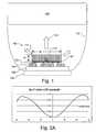
- FIG. 1illustrates a side view of a light source that includes an LED with a wavelength converting element that has a controlled non-uniform angular color distribution.
- FIG. 2illustrates a ⁇ u′v′ shift over angle for showing the angular color non-uniformity of the light source from FIG. 1 .
- FIGS. 3A and 3Billustrates an example of the light source used with a flash type application.
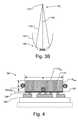
- FIG. 4illustrates a side view of the light source in a semi-side emitter configuration.
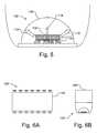
- FIG. 5illustrates another embodiment of the light source that emits light with a controlled non-uniform angular color dependency.
- FIGS. 6A and 6Billustrate a plan view and side view of a plurality of light sources used with a backlight type application.
- FIG. 7is a graph illustrating the absorption curve per 1 mm for PMMA acrylic, which is commonly used as a waveguide in a backlight application.
- FIG. 8is a graph illustrates the effect of the spectral absorption of the waveguide.
- FIG. 9is a graph illustrating the color shift due to a PMMA waveguide's (blue) absorption over distance.
- FIG. 10is a graph illustrating at theoretical PMMA waveguide's absorption using a light source having a controlled angular color non-uniformity.
- FIG. 1illustrates a side view of a light source 100 , including a light emitting diode (LED) 101 with a wavelength converting element 110 , which has a controlled non-uniform angular color distribution.
- FIG. 1also illustrates a device 120 used with the light source 100 with a lens 122 arrangement for reflecting the light from light source 100 to the device 120 .
- the device 120may be an application such as a flash type application or back lighting or other appropriate applications.
- the angular color non-uniformity of the light source 100is configured to be used with a light based device 120 so that the overall system, i.e., light source 100 and device 120 , becomes more efficient than a system that includes a conventional light source 100 with a uniform angular LED.
- the LED 101is illustrated as a flip-chip device with bond pads 102 located on the bottom surface of the LED 101 .
- the bond pads 102are bonded to contact elements 104 on a substrate 106 , which may be, e.g., ceramic or silicon.
- the substrate 106may be mounted on a heat sink 108 if desired. If desired, support structures other than the substrate 106 and heat sink 108 may be used.
- the LED 101may be a blue or ultraviolet (UV) LED and may be a high radiance device, such as the type described in U.S. Ser. No. 10/652,348, entitled “Package for a Semiconductor Light Emitting Device”, by Frank Wall et al., filed Aug. 29, 2003, Pub. No. 2005/0045901, having the same assignee as the present disclosure and which is incorporated herein by reference.
- the angular emission pattern of the LED 101can be lambertian (as illustrated in FIG. 1 ) or controlled using a photonic crystals such as lattice structures.
- a wavelength converting element 110mounted to the LED 101 is a wavelength converting element 110 that may be, e.g., a phosphor in a binder material, embedded in, e.g., silicone and molded over the LED 101 , or in a rigid ceramic slab, sometimes referred to herein as a “luminescent ceramic”.
- the ceramic slabsare generally self-supporting layers and may be translucent or transparent to particular wavelengths, which may reduce the scattering loss associated with non-transparent wavelength converting layers such as conformal layers. Luminescent ceramic layers may be more robust than thin film or conformal phosphor layers.
- Examples of phosphors that may be used in a binder, molded over the LED 101 , or in a luminescent ceramicinclude aluminum garnet phosphors with the general formula (Lu 1 ⁇ x ⁇ y ⁇ a ⁇ b Y x Gd y ) 3 (Al 1 ⁇ z Ga z ) 5 O 12 :Ce a Pr b wherein 0 ⁇ x ⁇ 1, 0 ⁇ y ⁇ 1, 0 ⁇ z ⁇ 0.1, 0 ⁇ a ⁇ 0.2 and 0 ⁇ b ⁇ 0.1, such as Lu 3 Al 5 O 12 :Ce 3+ and Y 3 Al 5 O 12 :Ce 3+ which emit light in the yellow-green range; and (Sr 1 ⁇ x ⁇ y Ba x Ca y ) 2 ⁇ z Si 5 ⁇ a Al a N 8 ⁇ a O a :Eu z 2+ wherein 0 ⁇ a ⁇ 5, 0 ⁇ x ⁇ 1, 0 ⁇ y ⁇ 1, and 0 ⁇ z ⁇ 1 such as Sr 2 Si 5 N 8 :Eu 2+ , which emit light in
- Suitable Y 3 Al 5 O 12 :Ce 3+ ceramic slabsmay be purchased from Baikowski International Corporation of Charlotte, N.C.
- the light source 100has both top emission and side emission of light, where the top emitted light 114 is bluish white and the side emitted light 115 is yellowish.
- the height H of the wavelength converting element 110or more specifically, the height/width (H/W) ratio, the angular dependency of the light can be controlled to produce a desired amount of bluish white light 114 and yellowish light 115 that is appropriate for the device 120 .
- H/Wheight/width
- FIG. 2Aillustrates a ⁇ u′v′ shift over angle showing one embodiment of the angular color non-uniformity of the light source 100 .
- the ⁇ u′v′ shift over angleis a measure of the color shift relative to a reference point.
- the light source 100produces a ⁇ u′v′ shift of >0.015 between 0° and 90° with respect to the 0° reference point. This is the maximum color over angle variation as measured within the angular range.
- FIG. 2Bshows an example of the ⁇ u′v′ for another light source 100 with a blue LED and Red/Green phosphors, that has been configured to produce a ⁇ u′v′>0.05 over angle.
- maximum ⁇ u′v′ over angle valuescan be created e.g. maximum ⁇ u′v′ over angle may be larger than 0.015, 0.03, 0.045 or 0.06 depending on the desired application, e.g., the device 120 , the light source 100 is to be used with.
- the device 120 using the light source 100then produces a spatial color uniformity of ⁇ u′v′ less than 0.015, e.g., less than 0.01 or 0.005.
- the light source 100is designed to produce a controlled angular color non-uniformity that is optimized for the particular device 120 with which the light source 100 is to be used.
- the light source 100is configured to produces a controlled angular color non-uniformity with a ⁇ u′v′ shift of >0.015 over angle, but when used with device 120 , the device 120 produces a spatial color uniformity of ⁇ u′v′ ⁇ 0.015.
- Different spatial color uniformities like ⁇ u′v′ ⁇ 0.05 to ⁇ u′v′ ⁇ 0.015are possible depending on the application requirements.
- medical monitors or other application that require a highly accurate representation of colormay be produced with a backlight in accordance with one embodiment having a ⁇ u′v′ ⁇ 0.05, whereas consumer monitors may be produced with a backlight having a ⁇ u′v′ ⁇ 0.01, and applications such as a camera flash may have a ⁇ u′v′ ⁇ 0.015.
- the efficiency of the light source 100can be increased as there is no need to block light from being emitted from the light source 100 . Consequently, the overall performance of the system, including the device 120 and the light source 100 is improved compared to systems in which a uniform angular LED is used.
- FIGS. 3A and 3Billustrates an example of the light source 100 that may be used with a flash type device 120 , e.g., for a camera.
- FIG. 2Billustrates light source 100 with an additional controlling element 112 , such as a dichroic filter, overlying the wavelength converting element 110 .
- the dichroic filter 112transmits light differently as a function of angle, which further aids in the control of the angular dependency.
- a scattering elementmay be used to appropriately reduce or control the angular dependency.
- the light source 100produces bluish white light 114 and yellowish light 115 that is reflected by the reflector 122 and mixed at the imaging target 124 .
- the light source 100may be a side (or semi-side) emitter in which no there is little top emission and significant side emission.
- FIG. 4illustrates light source 100 in a semi-side emitter configuration, in which no top reflector on the top surface 110 top of the wavelength converting element 110 is necessary. As illustrated in FIG. 4 , the angular emission pattern from the sides 110 side of the light source 100 is lambertian. By replacing a top reflector with increased height H of the wavelength converting element 110 with respect to the width W of the wavelength converting element 110 (which in this embodiment is the same as the width of the LED 101 ), the number of reflections of the light to the LED 101 is reduced.
- Reflections to the LED 101are inefficient and therefore by reducing the reflections to the LED 101 the losses in the system are reduced.
- the sides 110 side of the wavelength converting element 110have a greater area, which provides increased light extraction from the sides 110 side of the wavelength converting element 110 .
- the light source 100is optimized for applications requiring light extraction, as opposed to light collection. For example, in applications such as flash optical design, a small designed source is desired, so that optics can be kept small, while collecting most of the light and aim the light at a target of 1.05 ⁇ 0.8 meters at 1 meter distance.
- the Ce concentration within the wavelength converting elementmay be configured to produce the desired color point for the particular application. Additionally, scattering particles may be added to the wavelength converting element to assist in the light extraction into air.
- FIG. 5illustrates another embodiment of the light source 100 that emits light with a controlled angular color dependency.
- the light source 100includes a thin optically coupled laminate element 116 to the top surface of the wavelength converting element 110 , which may be, e.g., a dichroic layer, a scattering layer, or a red phosphor layer.
- the element 116may be placed between the wavelength converting element 110 and the LED 101 , particularly when the element 116 is a red phosphor layer, the wavelength converting element 110 is a greenish phosphor plate such as LUAG, and the LED 101 is a blue LED.
- the light source 100may include an overmolded dome lens 118 , which may be silicon, epoxy, or other appropriate material, which may also be to assist in the control of the angular color non-uniformity. If desired, the overmolded dome lens 118 need not be used.
- the top emitted light, illustrated by arrow 114is bluish white and has a lambertian emission profile.
- the side emitted light, illustrated by arrow 115is yellowish and has an isotropic emission profile that is configured by the height H of the wavelength converting element as well as by scattering.
- the angular dependent emission of light source 100may be translated into a uniform spatial color distribution in the desired application, such a backlight.
- FIGS. 6A and 6Billustrate a plan view and side view of a plurality of light source 100 used with a backlight type device 120 .
- the backlight 120extracts color, e.g., blue versus green/red, from a single light source 100 at different locations within the backlight.
- colore.g., blue versus green/red
- FIG. 7is a graph illustrating the absorption curve per 1 mm for PMMA acrylic, which is commonly used as a waveguide in a backlight application.
- the X axisrepresents wavelengths while the Y axis represents the percentage of absorption.
- FIG. 8is a graph illustrates the effect of the spectral absorption of the waveguide illustrating the change of the spectrum from the edge (illustrated by curve 202 ) and the center (illustrated by curve 204 ) of a 72′′ PMMA waveguide.
- the X axisrepresents wavelengths while the Y axis represents relative spectral distribution.
- the center 204 of the spectrum at the center of the waveguideincludes less blue light than the edge 202 of the waveguide.
- FIG. 9is a graph illustrating the theoretical color shift due to a PMMA waveguide's (blue) absorption in a 2-sided backlight over distance for a conventional light source having a uniform angular and spatial input.
- the X axisrepresents the diagonal position of the backlight in inches, while the Y axis represents the change in ⁇ u′v′ from the center to the edge.
- the conventional waveguide using a conventional uniform angular light sourcehas a ⁇ u′v′ that is greater than 0.01 and in fact is up to 0.02.
- FIG. 10illustrates a theoretical PMMA waveguide's absorption, similar to that shown in FIG.
- the resulting spatial color uniformityhas a ⁇ u′v′ of less than 0.01.
Landscapes
- Led Device Packages (AREA)
- Planar Illumination Modules (AREA)
- Non-Portable Lighting Devices Or Systems Thereof (AREA)
Abstract
Description
Claims (11)
Priority Applications (10)
| Application Number | Priority Date | Filing Date | Title |
|---|---|---|---|
| US12/236,527US8129735B2 (en) | 2008-09-24 | 2008-09-24 | LED with controlled angular non-uniformity |
| BRPI0913776ABRPI0913776A2 (en) | 2008-09-24 | 2009-09-21 | "apparatus comprising a light source comprising a light emitting diode and method comprising providing a light emitting diode" |
| JP2011527459AJP5926957B2 (en) | 2008-09-24 | 2009-09-21 | Apparatus and method with LED with controlled angular non-uniformity |
| TW098131839ATWI497748B (en) | 2008-09-24 | 2009-09-21 | Illuminated diode with controlled angular inconsistency |
| PCT/IB2009/054133WO2010035210A1 (en) | 2008-09-24 | 2009-09-21 | Led with controlled angular non-uniformity |
| RU2011116057/28ARU2504047C2 (en) | 2008-09-24 | 2009-09-21 | Led with controlled angular non-uniformity |
| KR1020117009083AKR101639458B1 (en) | 2008-09-24 | 2009-09-21 | Led with controlled angular non-uniformity |
| CN200980137466.3ACN102165613B (en) | 2008-09-24 | 2009-09-21 | LED with controlled angular non-uniformity |
| EP09787264.2AEP2332188B1 (en) | 2008-09-24 | 2009-09-21 | Method of controlling the angular non-uniformity of a light-emitting diode |
| JP2015209930AJP6531030B2 (en) | 2008-09-24 | 2015-10-26 | LED with controlled angular non-uniformity |
Applications Claiming Priority (1)
| Application Number | Priority Date | Filing Date | Title |
|---|---|---|---|
| US12/236,527US8129735B2 (en) | 2008-09-24 | 2008-09-24 | LED with controlled angular non-uniformity |
Publications (2)
| Publication Number | Publication Date |
|---|---|
| US20100072488A1 US20100072488A1 (en) | 2010-03-25 |
| US8129735B2true US8129735B2 (en) | 2012-03-06 |
Family
ID=41509056
Family Applications (1)
| Application Number | Title | Priority Date | Filing Date |
|---|---|---|---|
| US12/236,527Active2029-02-15US8129735B2 (en) | 2008-09-24 | 2008-09-24 | LED with controlled angular non-uniformity |
Country Status (9)
| Country | Link |
|---|---|
| US (1) | US8129735B2 (en) |
| EP (1) | EP2332188B1 (en) |
| JP (2) | JP5926957B2 (en) |
| KR (1) | KR101639458B1 (en) |
| CN (1) | CN102165613B (en) |
| BR (1) | BRPI0913776A2 (en) |
| RU (1) | RU2504047C2 (en) |
| TW (1) | TWI497748B (en) |
| WO (1) | WO2010035210A1 (en) |
Families Citing this family (18)
| Publication number | Priority date | Publication date | Assignee | Title |
|---|---|---|---|---|
| DE102010025608A1 (en)* | 2010-06-30 | 2012-01-05 | Osram Opto Semiconductors Gmbh | Optoelectronic component |
| EP2472612A1 (en)* | 2010-12-29 | 2012-07-04 | Koninklijke Philips Electronics N.V. | Improved angular color performance of white LED lighting systems |
| US9029887B2 (en) | 2011-04-22 | 2015-05-12 | Micron Technology, Inc. | Solid state lighting devices having improved color uniformity and associated methods |
| DE102012005658B4 (en)* | 2012-03-22 | 2013-10-24 | Schott Ag | White light generation |
| WO2014184701A1 (en) | 2013-05-15 | 2014-11-20 | Koninklijke Philips N.V. | Led with scattering features in substrate |
| US9976710B2 (en) | 2013-10-30 | 2018-05-22 | Lilibrand Llc | Flexible strip lighting apparatus and methods |
| WO2015064883A1 (en)* | 2013-11-01 | 2015-05-07 | Seoul Semiconductor Co., Ltd. | Light source module and backlight unit having the same |
| US9911907B2 (en)* | 2014-07-28 | 2018-03-06 | Epistar Corporation | Light-emitting apparatus |
| US10030825B2 (en) | 2015-08-03 | 2018-07-24 | Philips Lighting Holding B.V. | Lighting assembly with an optical element for reducing color over angle variation |
| US11060702B2 (en) | 2016-03-08 | 2021-07-13 | Ecosense Lighting Inc. | Lighting system with lens assembly |
| JP2018022844A (en) | 2016-08-05 | 2018-02-08 | 日亜化学工業株式会社 | Light emitting apparatus and method of manufacturing the same |
| US12388056B1 (en) | 2017-01-27 | 2025-08-12 | Korrus, Inc. | Linear lighting systems and processes |
| WO2018140727A1 (en) | 2017-01-27 | 2018-08-02 | Lilibrand Llc | Lighting systems with high color rendering index and uniform planar illumination |
| JP2018142567A (en)* | 2017-02-27 | 2018-09-13 | スタンレー電気株式会社 | Semiconductor light emitting device |
| US20180328552A1 (en) | 2017-03-09 | 2018-11-15 | Lilibrand Llc | Fixtures and lighting accessories for lighting devices |
| US11041609B2 (en) | 2018-05-01 | 2021-06-22 | Ecosense Lighting Inc. | Lighting systems and devices with central silicone module |
| US12040435B2 (en) | 2018-10-15 | 2024-07-16 | Sony Corporation | Light-emitting device and image display apparatus with reflection film on side surface and layers having different refractive indices |
| US11353200B2 (en) | 2018-12-17 | 2022-06-07 | Korrus, Inc. | Strip lighting system for direct input of high voltage driving power |
Citations (4)
| Publication number | Priority date | Publication date | Assignee | Title |
|---|---|---|---|---|
| EP1178544A2 (en) | 2000-07-31 | 2002-02-06 | Kabushiki Kaisha Toshiba | Semiconductor light emitting device and method for manufacturing same |
| US20060063289A1 (en)* | 2004-09-21 | 2006-03-23 | Negley Gerald H | Methods of coating semiconductor light emitting elements by evaporating solvent from a suspension |
| US20070152230A1 (en)* | 2006-01-05 | 2007-07-05 | Duong Dung T | Separate optical device for directing light from an LED |
| US20070284592A1 (en)* | 2006-06-12 | 2007-12-13 | Haase Michael A | Led device with re-emitting semiconductor construction and reflector |
Family Cites Families (17)
| Publication number | Priority date | Publication date | Assignee | Title |
|---|---|---|---|---|
| JP2002299698A (en)* | 2001-03-30 | 2002-10-11 | Sumitomo Electric Ind Ltd | Light emitting device |
| RU2219622C1 (en)* | 2002-10-25 | 2003-12-20 | Закрытое акционерное общество "Светлана-Оптоэлектроника" | Semiconductor white light source |
| JP2005294820A (en)* | 2004-03-12 | 2005-10-20 | Showa Denko Kk | Group iii nitride semiconductor light-emitting element, method of forming the element, and lamp and light source using the same |
| JP2005321727A (en)* | 2004-05-11 | 2005-11-17 | Sony Corp | Backlight device and color liquid crystal display |
| DE202004011015U1 (en)* | 2004-07-14 | 2004-11-11 | Tridonic Optoelectronics Gmbh | LED spotlight with funnel-shaped lens |
| JP2006073507A (en)* | 2004-08-06 | 2006-03-16 | Enplas Corp | Planar light source device and image display device |
| JP2008527706A (en)* | 2005-01-10 | 2008-07-24 | コーニンクレッカ フィリップス エレクトロニクス エヌ ヴィ | Illumination system with ceramic luminescence converter |
| JP2006196529A (en)* | 2005-01-11 | 2006-07-27 | Nichia Chem Ind Ltd | Light emitting device |
| JP2007116107A (en)* | 2005-09-22 | 2007-05-10 | Toshiba Lighting & Technology Corp | Light emitting device |
| KR100679947B1 (en)* | 2005-12-16 | 2007-02-08 | 루미마이크로 주식회사 | Structure and method for improving color temperature variation of light emitting diode |
| JP2007173373A (en)* | 2005-12-20 | 2007-07-05 | Toshiba Lighting & Technology Corp | Light emitting device |
| JP5082427B2 (en)* | 2005-12-26 | 2012-11-28 | 東芝ライテック株式会社 | Light emitting device |
| JP2007234818A (en)* | 2006-02-28 | 2007-09-13 | Toshiba Lighting & Technology Corp | Light emitting device |
| JP4473284B2 (en)* | 2006-03-31 | 2010-06-02 | Dowaエレクトロニクス株式会社 | Light emitting device and manufacturing method thereof |
| JP4435123B2 (en)* | 2006-08-11 | 2010-03-17 | ソニー株式会社 | Driving method of display device |
| JP4134222B2 (en)* | 2006-09-21 | 2008-08-20 | シャープ株式会社 | Backlight device |
| EP2089916A1 (en)* | 2006-11-07 | 2009-08-19 | Philips Intellectual Property & Standards GmbH | Arrangement for emitting mixed light |
- 2008
- 2008-09-24USUS12/236,527patent/US8129735B2/enactiveActive
- 2009
- 2009-09-21RURU2011116057/28Apatent/RU2504047C2/enactive
- 2009-09-21WOPCT/IB2009/054133patent/WO2010035210A1/enactiveApplication Filing
- 2009-09-21EPEP09787264.2Apatent/EP2332188B1/enactiveActive
- 2009-09-21CNCN200980137466.3Apatent/CN102165613B/enactiveActive
- 2009-09-21JPJP2011527459Apatent/JP5926957B2/enactiveActive
- 2009-09-21KRKR1020117009083Apatent/KR101639458B1/enactiveActive
- 2009-09-21BRBRPI0913776Apatent/BRPI0913776A2/ennot_activeApplication Discontinuation
- 2009-09-21TWTW098131839Apatent/TWI497748B/enactive
- 2015
- 2015-10-26JPJP2015209930Apatent/JP6531030B2/enactiveActive
Patent Citations (4)
| Publication number | Priority date | Publication date | Assignee | Title |
|---|---|---|---|---|
| EP1178544A2 (en) | 2000-07-31 | 2002-02-06 | Kabushiki Kaisha Toshiba | Semiconductor light emitting device and method for manufacturing same |
| US20060063289A1 (en)* | 2004-09-21 | 2006-03-23 | Negley Gerald H | Methods of coating semiconductor light emitting elements by evaporating solvent from a suspension |
| US20070152230A1 (en)* | 2006-01-05 | 2007-07-05 | Duong Dung T | Separate optical device for directing light from an LED |
| US20070284592A1 (en)* | 2006-06-12 | 2007-12-13 | Haase Michael A | Led device with re-emitting semiconductor construction and reflector |
Non-Patent Citations (1)
| Title |
|---|
| International Search Report, PCT/IB2009/054133. |
Also Published As
| Publication number | Publication date |
|---|---|
| US20100072488A1 (en) | 2010-03-25 |
| RU2011116057A (en) | 2012-10-27 |
| EP2332188B1 (en) | 2019-06-19 |
| JP5926957B2 (en) | 2016-05-25 |
| JP6531030B2 (en) | 2019-06-12 |
| RU2504047C2 (en) | 2014-01-10 |
| TWI497748B (en) | 2015-08-21 |
| JP2012503860A (en) | 2012-02-09 |
| WO2010035210A1 (en) | 2010-04-01 |
| EP2332188A1 (en) | 2011-06-15 |
| KR20110055744A (en) | 2011-05-25 |
| BRPI0913776A2 (en) | 2015-10-20 |
| CN102165613A (en) | 2011-08-24 |
| TW201019512A (en) | 2010-05-16 |
| CN102165613B (en) | 2013-07-24 |
| JP2016015524A (en) | 2016-01-28 |
| KR101639458B1 (en) | 2016-07-13 |
Similar Documents
| Publication | Publication Date | Title |
|---|---|---|
| US8129735B2 (en) | LED with controlled angular non-uniformity | |
| KR100946015B1 (en) | White light emitting device and light source module for LCD backlight using the same | |
| TWI537365B (en) | White LED, display device and lighting device | |
| EP1566848A2 (en) | Wavelength converted semiconductor light emitting device | |
| TW200935633A (en) | Display device and illumination device | |
| TW200836382A (en) | White light emitting device and white light source module using the same | |
| KR20120025367A (en) | Light emitting device | |
| WO2006003930A1 (en) | Light emitting device and illuminator employing it, back light for display, and display | |
| TW201306325A (en) | White light emitting element, display device, and lighting device using the same | |
| JP2011159832A (en) | Semiconductor light emitting device | |
| US10533729B2 (en) | Light source with LED chip and luminophore layer | |
| JP2011511445A (en) | Illumination device for backlighting display and display equipped with the illumination device | |
| JP2025011107A (en) | Wide-gamut photoluminescent wavelength-converted white-light-emitting device | |
| US9200200B2 (en) | Phosphor, light emitting device, surface light source device, display device and illumination device | |
| US20110095328A1 (en) | Close proximity collimator for led | |
| JP6798772B2 (en) | Lighting device | |
| JP2013511828A (en) | Light emitting device | |
| WO2024143215A1 (en) | Light-emitting device | |
| KR20130128516A (en) | Lighting device |
Legal Events
| Date | Code | Title | Description |
|---|---|---|---|
| AS | Assignment | Owner name:KONINKLIJKE PHILIPS ELECTRONICS N V,NETHERLANDS Free format text:ASSIGNMENT OF ASSIGNORS INTEREST;ASSIGNORS:BIERHUIZEN, SERGE J.;SMITT, WILLEM SILLEVIS;REEL/FRAME:021576/0367 Effective date:20080829 Owner name:PHILIPS LUMILEDS LIGHTING COMPANY, LLC,CALIFORNIA Free format text:ASSIGNMENT OF ASSIGNORS INTEREST;ASSIGNORS:BIERHUIZEN, SERGE J.;SMITT, WILLEM SILLEVIS;REEL/FRAME:021576/0367 Effective date:20080829 Owner name:KONINKLIJKE PHILIPS ELECTRONICS N V, NETHERLANDS Free format text:ASSIGNMENT OF ASSIGNORS INTEREST;ASSIGNORS:BIERHUIZEN, SERGE J.;SMITT, WILLEM SILLEVIS;REEL/FRAME:021576/0367 Effective date:20080829 Owner name:PHILIPS LUMILEDS LIGHTING COMPANY, LLC, CALIFORNIA Free format text:ASSIGNMENT OF ASSIGNORS INTEREST;ASSIGNORS:BIERHUIZEN, SERGE J.;SMITT, WILLEM SILLEVIS;REEL/FRAME:021576/0367 Effective date:20080829 | |
| STCF | Information on status: patent grant | Free format text:PATENTED CASE | |
| FPAY | Fee payment | Year of fee payment:4 | |
| AS | Assignment | Owner name:DEUTSCHE BANK AG NEW YORK BRANCH, AS COLLATERAL AGENT, NEW YORK Free format text:SECURITY INTEREST;ASSIGNOR:LUMILEDS LLC;REEL/FRAME:043108/0001 Effective date:20170630 Owner name:DEUTSCHE BANK AG NEW YORK BRANCH, AS COLLATERAL AG Free format text:SECURITY INTEREST;ASSIGNOR:LUMILEDS LLC;REEL/FRAME:043108/0001 Effective date:20170630 | |
| AS | Assignment | Owner name:LUMILEDS LLC, CALIFORNIA Free format text:ASSIGNMENT OF ASSIGNORS INTEREST;ASSIGNOR:KONINKLIJKE PHILIPS ELECTRONICS N.V.;REEL/FRAME:044931/0651 Effective date:20170428 | |
| AS | Assignment | Owner name:LUMILEDS LLC, CALIFORNIA Free format text:CORRECTIVE ASSIGNMENT TO CORRECT THE CONVEYING PARTY DATA PREVIOUSLY RECORDED AT REEL: 044931 FRAME: 0651. ASSIGNOR(S) HEREBY CONFIRMS THE ASSIGNMENT;ASSIGNOR:KONINKLIJKE PHILIPS N.V.;REEL/FRAME:047304/0203 Effective date:20170408 | |
| AS | Assignment | Owner name:KONINKLIJKE PHILIPS N.V., NETHERLANDS Free format text:CHANGE OF NAME;ASSIGNOR:KONINKLIJKE PHILIPS ELECTRONICS N.V.;REEL/FRAME:047368/0237 Effective date:20130515 | |
| MAFP | Maintenance fee payment | Free format text:PAYMENT OF MAINTENANCE FEE, 8TH YEAR, LARGE ENTITY (ORIGINAL EVENT CODE: M1552); ENTITY STATUS OF PATENT OWNER: LARGE ENTITY Year of fee payment:8 | |
| AS | Assignment | Owner name:SOUND POINT AGENCY LLC, NEW YORK Free format text:SECURITY INTEREST;ASSIGNORS:LUMILEDS LLC;LUMILEDS HOLDING B.V.;REEL/FRAME:062299/0338 Effective date:20221230 | |
| MAFP | Maintenance fee payment | Free format text:PAYMENT OF MAINTENANCE FEE, 12TH YEAR, LARGE ENTITY (ORIGINAL EVENT CODE: M1553); ENTITY STATUS OF PATENT OWNER: LARGE ENTITY Year of fee payment:12 | |
| AS | Assignment | Owner name:LUMILEDS HOLDING B.V., NETHERLANDS Free format text:RELEASE BY SECURED PARTY;ASSIGNOR:SOUND POINT AGENCY LLC;REEL/FRAME:070046/0001 Effective date:20240731 Owner name:LUMILEDS LLC, CALIFORNIA Free format text:RELEASE BY SECURED PARTY;ASSIGNOR:SOUND POINT AGENCY LLC;REEL/FRAME:070046/0001 Effective date:20240731 |