US8128703B2 - Fixed-bearing knee prosthesis having interchangeable components - Google Patents
Fixed-bearing knee prosthesis having interchangeable componentsDownload PDFInfo
- Publication number
- US8128703B2 US8128703B2US12/620,034US62003409AUS8128703B2US 8128703 B2US8128703 B2US 8128703B2US 62003409 AUS62003409 AUS 62003409AUS 8128703 B2US8128703 B2US 8128703B2
- Authority
- US
- United States
- Prior art keywords
- anterior
- buttress
- platform
- posterior
- arm
- Prior art date
- Legal status (The legal status is an assumption and is not a legal conclusion. Google has not performed a legal analysis and makes no representation as to the accuracy of the status listed.)
- Active
Links
Images


Classifications
- A—HUMAN NECESSITIES
- A61—MEDICAL OR VETERINARY SCIENCE; HYGIENE
- A61F—FILTERS IMPLANTABLE INTO BLOOD VESSELS; PROSTHESES; DEVICES PROVIDING PATENCY TO, OR PREVENTING COLLAPSING OF, TUBULAR STRUCTURES OF THE BODY, e.g. STENTS; ORTHOPAEDIC, NURSING OR CONTRACEPTIVE DEVICES; FOMENTATION; TREATMENT OR PROTECTION OF EYES OR EARS; BANDAGES, DRESSINGS OR ABSORBENT PADS; FIRST-AID KITS
- A61F2/00—Filters implantable into blood vessels; Prostheses, i.e. artificial substitutes or replacements for parts of the body; Appliances for connecting them with the body; Devices providing patency to, or preventing collapsing of, tubular structures of the body, e.g. stents
- A61F2/02—Prostheses implantable into the body
- A61F2/30—Joints
- A61F2/38—Joints for elbows or knees
- A61F2/3877—Patellae or trochleae
- A—HUMAN NECESSITIES
- A61—MEDICAL OR VETERINARY SCIENCE; HYGIENE
- A61F—FILTERS IMPLANTABLE INTO BLOOD VESSELS; PROSTHESES; DEVICES PROVIDING PATENCY TO, OR PREVENTING COLLAPSING OF, TUBULAR STRUCTURES OF THE BODY, e.g. STENTS; ORTHOPAEDIC, NURSING OR CONTRACEPTIVE DEVICES; FOMENTATION; TREATMENT OR PROTECTION OF EYES OR EARS; BANDAGES, DRESSINGS OR ABSORBENT PADS; FIRST-AID KITS
- A61F2/00—Filters implantable into blood vessels; Prostheses, i.e. artificial substitutes or replacements for parts of the body; Appliances for connecting them with the body; Devices providing patency to, or preventing collapsing of, tubular structures of the body, e.g. stents
- A61F2/02—Prostheses implantable into the body
- A61F2/30—Joints
- A61F2/38—Joints for elbows or knees
- A61F2/389—Tibial components
- A—HUMAN NECESSITIES
- A61—MEDICAL OR VETERINARY SCIENCE; HYGIENE
- A61F—FILTERS IMPLANTABLE INTO BLOOD VESSELS; PROSTHESES; DEVICES PROVIDING PATENCY TO, OR PREVENTING COLLAPSING OF, TUBULAR STRUCTURES OF THE BODY, e.g. STENTS; ORTHOPAEDIC, NURSING OR CONTRACEPTIVE DEVICES; FOMENTATION; TREATMENT OR PROTECTION OF EYES OR EARS; BANDAGES, DRESSINGS OR ABSORBENT PADS; FIRST-AID KITS
- A61F2/00—Filters implantable into blood vessels; Prostheses, i.e. artificial substitutes or replacements for parts of the body; Appliances for connecting them with the body; Devices providing patency to, or preventing collapsing of, tubular structures of the body, e.g. stents
- A61F2/02—Prostheses implantable into the body
- A61F2/30—Joints
- A61F2002/30001—Additional features of subject-matter classified in A61F2/28, A61F2/30 and subgroups thereof
- A61F2002/30108—Shapes
- A61F2002/3011—Cross-sections or two-dimensional shapes
- A61F2002/30159—Concave polygonal shapes
- A61F2002/30172—T-shaped
- A—HUMAN NECESSITIES
- A61—MEDICAL OR VETERINARY SCIENCE; HYGIENE
- A61F—FILTERS IMPLANTABLE INTO BLOOD VESSELS; PROSTHESES; DEVICES PROVIDING PATENCY TO, OR PREVENTING COLLAPSING OF, TUBULAR STRUCTURES OF THE BODY, e.g. STENTS; ORTHOPAEDIC, NURSING OR CONTRACEPTIVE DEVICES; FOMENTATION; TREATMENT OR PROTECTION OF EYES OR EARS; BANDAGES, DRESSINGS OR ABSORBENT PADS; FIRST-AID KITS
- A61F2/00—Filters implantable into blood vessels; Prostheses, i.e. artificial substitutes or replacements for parts of the body; Appliances for connecting them with the body; Devices providing patency to, or preventing collapsing of, tubular structures of the body, e.g. stents
- A61F2/02—Prostheses implantable into the body
- A61F2/30—Joints
- A61F2002/30001—Additional features of subject-matter classified in A61F2/28, A61F2/30 and subgroups thereof
- A61F2002/30108—Shapes
- A61F2002/3011—Cross-sections or two-dimensional shapes
- A61F2002/30159—Concave polygonal shapes
- A61F2002/30181—Y-shaped
- A—HUMAN NECESSITIES
- A61—MEDICAL OR VETERINARY SCIENCE; HYGIENE
- A61F—FILTERS IMPLANTABLE INTO BLOOD VESSELS; PROSTHESES; DEVICES PROVIDING PATENCY TO, OR PREVENTING COLLAPSING OF, TUBULAR STRUCTURES OF THE BODY, e.g. STENTS; ORTHOPAEDIC, NURSING OR CONTRACEPTIVE DEVICES; FOMENTATION; TREATMENT OR PROTECTION OF EYES OR EARS; BANDAGES, DRESSINGS OR ABSORBENT PADS; FIRST-AID KITS
- A61F2/00—Filters implantable into blood vessels; Prostheses, i.e. artificial substitutes or replacements for parts of the body; Appliances for connecting them with the body; Devices providing patency to, or preventing collapsing of, tubular structures of the body, e.g. stents
- A61F2/02—Prostheses implantable into the body
- A61F2/30—Joints
- A61F2002/30001—Additional features of subject-matter classified in A61F2/28, A61F2/30 and subgroups thereof
- A61F2002/30316—The prosthesis having different structural features at different locations within the same prosthesis; Connections between prosthetic parts; Special structural features of bone or joint prostheses not otherwise provided for
- A61F2002/30329—Connections or couplings between prosthetic parts, e.g. between modular parts; Connecting elements
- A61F2002/30476—Connections or couplings between prosthetic parts, e.g. between modular parts; Connecting elements locked by an additional locking mechanism
- A61F2002/305—Snap connection
- A—HUMAN NECESSITIES
- A61—MEDICAL OR VETERINARY SCIENCE; HYGIENE
- A61F—FILTERS IMPLANTABLE INTO BLOOD VESSELS; PROSTHESES; DEVICES PROVIDING PATENCY TO, OR PREVENTING COLLAPSING OF, TUBULAR STRUCTURES OF THE BODY, e.g. STENTS; ORTHOPAEDIC, NURSING OR CONTRACEPTIVE DEVICES; FOMENTATION; TREATMENT OR PROTECTION OF EYES OR EARS; BANDAGES, DRESSINGS OR ABSORBENT PADS; FIRST-AID KITS
- A61F2/00—Filters implantable into blood vessels; Prostheses, i.e. artificial substitutes or replacements for parts of the body; Appliances for connecting them with the body; Devices providing patency to, or preventing collapsing of, tubular structures of the body, e.g. stents
- A61F2/02—Prostheses implantable into the body
- A61F2/30—Joints
- A61F2002/30001—Additional features of subject-matter classified in A61F2/28, A61F2/30 and subgroups thereof
- A61F2002/30316—The prosthesis having different structural features at different locations within the same prosthesis; Connections between prosthetic parts; Special structural features of bone or joint prostheses not otherwise provided for
- A61F2002/30535—Special structural features of bone or joint prostheses not otherwise provided for
- A61F2002/30604—Special structural features of bone or joint prostheses not otherwise provided for modular
- A61F2002/30616—Sets comprising a plurality of prosthetic parts of different sizes or orientations
- A—HUMAN NECESSITIES
- A61—MEDICAL OR VETERINARY SCIENCE; HYGIENE
- A61F—FILTERS IMPLANTABLE INTO BLOOD VESSELS; PROSTHESES; DEVICES PROVIDING PATENCY TO, OR PREVENTING COLLAPSING OF, TUBULAR STRUCTURES OF THE BODY, e.g. STENTS; ORTHOPAEDIC, NURSING OR CONTRACEPTIVE DEVICES; FOMENTATION; TREATMENT OR PROTECTION OF EYES OR EARS; BANDAGES, DRESSINGS OR ABSORBENT PADS; FIRST-AID KITS
- A61F2/00—Filters implantable into blood vessels; Prostheses, i.e. artificial substitutes or replacements for parts of the body; Appliances for connecting them with the body; Devices providing patency to, or preventing collapsing of, tubular structures of the body, e.g. stents
- A61F2/02—Prostheses implantable into the body
- A61F2/30—Joints
- A61F2/30767—Special external or bone-contacting surface, e.g. coating for improving bone ingrowth
- A61F2/30771—Special external or bone-contacting surface, e.g. coating for improving bone ingrowth applied in original prostheses, e.g. holes or grooves
- A61F2002/30878—Special external or bone-contacting surface, e.g. coating for improving bone ingrowth applied in original prostheses, e.g. holes or grooves with non-sharp protrusions, for instance contacting the bone for anchoring, e.g. keels, pegs, pins, posts, shanks, stems, struts
- A—HUMAN NECESSITIES
- A61—MEDICAL OR VETERINARY SCIENCE; HYGIENE
- A61F—FILTERS IMPLANTABLE INTO BLOOD VESSELS; PROSTHESES; DEVICES PROVIDING PATENCY TO, OR PREVENTING COLLAPSING OF, TUBULAR STRUCTURES OF THE BODY, e.g. STENTS; ORTHOPAEDIC, NURSING OR CONTRACEPTIVE DEVICES; FOMENTATION; TREATMENT OR PROTECTION OF EYES OR EARS; BANDAGES, DRESSINGS OR ABSORBENT PADS; FIRST-AID KITS
- A61F2220/00—Fixations or connections for prostheses classified in groups A61F2/00 - A61F2/26 or A61F2/82 or A61F9/00 or A61F11/00 or subgroups thereof
- A61F2220/0025—Connections or couplings between prosthetic parts, e.g. between modular parts; Connecting elements
- A—HUMAN NECESSITIES
- A61—MEDICAL OR VETERINARY SCIENCE; HYGIENE
- A61F—FILTERS IMPLANTABLE INTO BLOOD VESSELS; PROSTHESES; DEVICES PROVIDING PATENCY TO, OR PREVENTING COLLAPSING OF, TUBULAR STRUCTURES OF THE BODY, e.g. STENTS; ORTHOPAEDIC, NURSING OR CONTRACEPTIVE DEVICES; FOMENTATION; TREATMENT OR PROTECTION OF EYES OR EARS; BANDAGES, DRESSINGS OR ABSORBENT PADS; FIRST-AID KITS
- A61F2230/00—Geometry of prostheses classified in groups A61F2/00 - A61F2/26 or A61F2/82 or A61F9/00 or A61F11/00 or subgroups thereof
- A61F2230/0002—Two-dimensional shapes, e.g. cross-sections
- A61F2230/0028—Shapes in the form of latin or greek characters
- A61F2230/0052—T-shaped
- A—HUMAN NECESSITIES
- A61—MEDICAL OR VETERINARY SCIENCE; HYGIENE
- A61F—FILTERS IMPLANTABLE INTO BLOOD VESSELS; PROSTHESES; DEVICES PROVIDING PATENCY TO, OR PREVENTING COLLAPSING OF, TUBULAR STRUCTURES OF THE BODY, e.g. STENTS; ORTHOPAEDIC, NURSING OR CONTRACEPTIVE DEVICES; FOMENTATION; TREATMENT OR PROTECTION OF EYES OR EARS; BANDAGES, DRESSINGS OR ABSORBENT PADS; FIRST-AID KITS
- A61F2230/00—Geometry of prostheses classified in groups A61F2/00 - A61F2/26 or A61F2/82 or A61F9/00 or A61F11/00 or subgroups thereof
- A61F2230/0002—Two-dimensional shapes, e.g. cross-sections
- A61F2230/0028—Shapes in the form of latin or greek characters
- A61F2230/006—Y-shaped
Definitions
- the present disclosurerelates generally to an implantable orthopaedic prosthesis, and more particularly to an implantable knee prosthesis.
- the joint replacement proceduremay involve the use of a prosthesis which is implanted into one or more of the patient's bones.
- a tibial trayis implanted into the patient's tibia.
- a bearingis secured to the tibial tray.
- the condyle surfaces of a replacement femoral componentbear against the tibial bearing.
- knee prosthesisis a fixed-bearing knee prosthesis.
- the bearing of a fixed-bearing knee prosthesisdoes not move relative to the tibial tray.
- Fixed-bearing designsare commonly used when the condition of the patient's soft tissue (i.e., knee ligaments) does not allow for the use of a knee prosthesis having a mobile bearing.
- the components of a fixed-bearing knee prosthesisare typically provided by the manufacturer in matching sizes.
- most currently available fixed-bearing knee prosthesesallow the surgeon to use a number of bearing sizes for a particular size of femoral component, but each bearing size is generally matched to a particular size of tibial tray.
- a fixed-bearing knee prosthesisincludes a femoral component having a medial condyle surface and a lateral condyle surface.
- the prosthesisalso includes a bearing having a medial bearing surface configured to articulate with the medial condyle surface of the femoral component, and a lateral bearing surface configured to articulate with the lateral condyle surface of the femoral component.
- a tibial trayis secured to the bearing.
- the tibial trayhas a platform with an elongated stem extending downwardly from a lower surface thereof.
- the platformhas a posterior buttress extending along a posterior section of a perimeter of the platform and extending upwardly from an upper surface of the platform.
- An anterior buttressextends along an anterior section of the perimeter of the platform and upwardly from the upper surface of the platform.
- the posterior buttressis generally Y-shaped and has a first arm extending along a posterior edge of the platform and having a first undercut defined therein.
- a second armextends along the posterior edge of the platform in a direction away from the first arm and has a second undercut defined therein.
- a third armextends anteriorly away from the first arm and the second arm.
- a first imaginary lineextends along a lateral-most edge of the first arm, with a second imaginary line extending along a medial-most edge of the second arm and intersecting the first imaginary line to define an angle of intersection therebetween.
- the angle of intersection of the imaginary linesis between 45-145°. In some illustrative embodiments, the angle of intersection of the imaginary lines is between 60-120°. In a specific illustrative embodiment, the angle of intersection of the imaginary lines is approximately 90°.
- the anterior buttressis generally T-shaped.
- the anterior buttressincludes a first arm extending along an anterior edge of the platform with a first undercut defined therein, and a second arm extending along the anterior edge of the platform in a direction away from the first arm and with a second undercut defined therein.
- a third armextends posteriorly away from the first arm and the second arm.
- the third arm of the posterior buttressmay be contiguous with the third arm of the anterior buttress.
- the bearingmay include a first posterior tab positioned in the first undercut defined in the first arm of the posterior buttress, a second posterior tab positioned in the second undercut defined in the second arm of the posterior buttress, a first anterior tab positioned in the first undercut defined in the first arm of the anterior buttress, and a second anterior tab positioned in the second undercut defined in the second arm of the anterior buttress.
- Both the medial bearing surface and the lateral bearing surfaceare defined in the upper surface of the bearing.
- the lower surface of the bearingcontacts the upper surface of the platform and includes a posterior recess and an anterior recess formed therein.
- the posterior buttressis positioned in the posterior recess and the anterior buttress is positioned in the anterior recess.
- the posterior recessmay be contiguous with the anterior recess.
- a fixed-bearing knee prosthesisincludes a femoral component having a medial condyle surface and a lateral condyle surface.
- the prosthesisalso includes a bearing having a medial bearing surface configured to articulate with the medial condyle surface of the femoral component, and a lateral bearing surface configured to articulate with the lateral condyle surface of the femoral component.
- a tibial trayis secured to the bearing.
- the tibial trayhas a platform with an elongated stem extending downwardly from a lower surface thereof.
- the platformhas a posterior buttress extending along a posterior section of a perimeter of the platform and extending upwardly from an upper surface of the platform.
- An anterior buttressextends along an anterior section of the perimeter of the platform and upwardly from the upper surface of the platform.
- the posterior buttressis generally Y-shaped and has a first arm extending along a posterior edge of the platform with a first undercut defined therein, and a second arm extending along the posterior edge of the platform in a direction away from the first arm with a second undercut defined therein.
- a third armextends anteriorly away from the first arm and the second arm.
- the anterior buttressincludes a first arm extending along an anterior edge of the platform with a first undercut defined therein.
- a second arm of the anterior buttressextends along the anterior edge of the platform in a direction away from the first arm of the anterior buttress with a second undercut defined therein.
- a first imaginary lineextends along a posterior-most edge of the first arm of the anterior buttress and a posterior-most edge of the second arm of the anterior buttress.
- a second imaginary lineextends along the longitudinal axis of the third arm of the posterior buttress and intersects the first imaginary line to define an angle of intersection therebetween. The angle of intersection is approximately 90°.
- the anterior buttressmay include a third arm extending posteriorly away from the first arm and the second arm in a direction parallel to the second imaginary line.
- the third arm of the posterior buttressmay be contiguous with the third arm of the anterior buttress.
- the bearingmay include a first posterior tab positioned in the first undercut defined in the first arm of the posterior buttress, a second posterior tab positioned in the second undercut defined in the second arm of the posterior buttress, a first anterior tab positioned in the first undercut defined in the first arm of the anterior buttress, and a second anterior tab positioned in the second undercut defined in the second arm of the anterior buttress.
- Both the medial bearing surface and the lateral bearing surfaceare defined in the upper surface of the bearing.
- the lower surface of the bearingcontacts the upper surface of the platform and includes a posterior recess and an anterior recess formed therein.
- the posterior buttressis positioned in the posterior recess and the anterior buttress is positioned in the anterior recess.
- the posterior recessmay be contiguous with the anterior recess.
- a fixed-bearing knee prosthesisincludes a femoral component having a medial condyle surface and a lateral condyle surface, and a tibial tray having a platform with an elongated stem extending downwardly from a lower surface thereof.
- the platformhas a generally Y-shaped posterior buttress extending upwardly from an upper surface of the platform.
- a pair of arms of the posterior buttressextend along a posterior section of a perimeter of the platform. Each of the pair of arms has an undercut defined therein.
- the platformalso has an anterior buttress extending along an anterior section of the perimeter of the platform and extending upwardly from the upper surface of the platform.
- the knee prosthesisalso includes a plurality of bearings configured to be secured to the tibial tray.
- Each of the plurality of bearingshas a width that is different from at least some of the other of the plurality of bearings.
- Each of the plurality of bearingsalso has an upper surface having a medial bearing surface configured to articulate with the medial condyle surface of the femoral component and a lateral bearing surface configured to articulate with the lateral condyle surface of the femoral component.
- a lower surface of each of the plurality of bearingshas at least one recess defined therein to receive the posterior buttress and the anterior buttress.
- Each of the plurality of bearingsalso includes a pair of posterior tabs arranged to be respectively received in the undercuts defined in the pair of arms of the posterior buttress.
- the recess of the bearingmay define a single, contiguous recess that receives both the posterior buttress and the anterior buttress.
- the anterior buttressmay be generally T-shaped with a pair of arms extending along an anterior edge of the platform.
- Each of the pair of arms of the anterior buttressmay have an undercut defined therein.
- Each of the plurality of bearingsmay further include a pair of anterior tabs arranged to be respectively received in the undercuts defined in the pair of arms of the anterior buttress.
- the posterior buttressmay be contiguous with the anterior buttress.
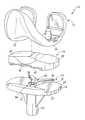
- FIG. 1is an exploded perspective view of a fixed-bearing knee prosthesis
- FIG. 2is a bottom perspective view of the bearing of the knee prosthesis of FIG. 1 ;
- FIG. 3is a perspective view of the tibial tray of the knee prosthesis of FIG. 1 ;
- FIG. 4is a plan view of the tibial tray of the knee prosthesis of FIG. 1 ;
- FIG. 5is a diagrammatic plan view of a number of differently sized tibial trays of the knee prosthesis of FIG. 1 ;
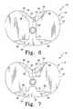
- FIGS. 6-9are similar to FIG. 4 , but showing different embodiments of the tibial tray.
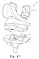
- FIGS. 10-14are similar to FIGS. 1-5 , respectively, but showing another embodiment of a fixed-bearing knee prosthesis.
- Terms representing anatomical referencessuch as anterior, posterior, medial, lateral, superior, inferior, etcetera, may be used throughout this disclosure in reference to both the orthopaedic implants described herein and a patient's natural anatomy. Such terms have well-understood meanings in both the study of anatomy and the field of orthopaedics. Use of such anatomical reference terms in the specification and claims is intended to be consistent with their well-understood meanings unless noted otherwise.
- the knee prosthesis 10includes a femoral component 12 , a tibial tray 14 , and a bearing 16 .
- the tibial tray 14includes a platform 18 having a fixation member, such as an elongated stem 20 , extending away from its lower surface 22 .
- the elongated tibial stem 20is configured to be implanted into a surgically prepared end of a patient's tibia (not shown). It should be appreciated that other fixation members, such as one or more short pegs or posts, may be used in lieu of the elongated stem 20 .
- the bearing 16is securable to the tibial tray 14 .
- the bearing 16may be snap-fit to the tibial tray 14 . In such a way, the bearing 16 is fixed relative to the tibial tray 14 (i.e., it is not rotatable or moveable in the anterior/posterior or medial/lateral directions).
- the bearing 16includes a lateral bearing surface 26 and a medial bearing surface 28 .
- the bearing surfaces 26 , 28are configured to articulate with a lateral condyle surface 30 and a medial condyle surface 32 , respectively, of the femoral component 12 .
- the femoral component 12is configured to be implanted into a surgically prepared end of the patient's femur (not shown), and is configured to emulate the configuration of the patient's natural femoral condyles.
- the lateral condyle surface 30 and the medial condyle surface 32are configured (e.g., curved) in a manner which mimics the condyles of the natural femur.
- the lateral condyle surface 30 and the medial condyle surface 32are spaced apart from one another thereby defining an intercondylar notch therebetween.
- the components of the knee prosthesis 10 that engage the natural bonemay be constructed with a biocompatible metal, such as a cobalt chrome alloy, although other materials may also be used.
- the bone engaging surfaces of these componentsmay be textured to facilitate cementing the component to the bone. Such surfaces may also be porous coated to promote bone ingrowth for permanent fixation.
- the bearing 16may be constructed with a material that allows for smooth articulation between the bearing 16 and the femoral component 12 , such as a polymeric material.
- a polymeric materialis polyethylene such as ultrahigh molecular weight polyethylene (UHMWPE).
- the lower surface 36 of the bearing 16includes a lateral pedestal 34 and a medial pedestal 38 .
- the pedestals 34 , 38have a number of posterior tabs 40 defined therein.
- a number of anterior tabs 42are also defined in the bearing 16 .
- a generally Y-shaped posterior buttress 44extends upwardly from the upper surface 24 of the tibial tray 14 .
- the posterior buttress 44has a pair of arms 46 , 48 extending along a posterior section of the perimeter of tibial tray's platform 18 .
- the lateral arm 46 of the posterior buttress 44extends along the posterior edge 50 on the lateral side of the platform 18
- the medial arm 48 of the posterior buttress 44extends along the posterior edge 50 on the medial side of the platform 18 in a direction away from the lateral arm 46 .
- a third arm 52 of the posterior buttress 44extends anteriorly away from the intersection of the lateral arm 46 and the medial arm 48 (i.e., in a direction toward the center of the platform 18 ).
- the posterior buttress 44has a pair of undercuts 54 , 56 defined therein. Specifically, the lateral undercut 54 is defined in the lateral arm 46 of the posterior buttress 44 , with the medial undercut 56 being defined in the medial arm 48 of the posterior buttress 44 .
- a generally T-shaped anterior buttress 64extends upwardly from the upper surface 24 of the tibial tray 14 .
- the anterior buttress 64has a pair of arms 66 , 68 extending along an anterior section of the perimeter of tibial tray's platform 18 .
- the lateral arm 66 of the anterior buttress 64extends along the anterior edge 70 on the lateral side of the platform 18
- the medial arm 68 of the anterior buttress 64extends along the anterior edge 70 on the medial side of the platform 18 in a direction away from the lateral arm 66 .
- a third arm 72 of the anterior buttress 64extends posteriorly away from the intersection of the lateral arm 66 and the medial arm 68 (i.e., in a direction toward the center of the platform 18 ).
- the anterior buttress 64has a pair of undercuts 74 , 76 defined therein. Specifically, the lateral undercut 74 is defined in the lateral arm 66 of the anterior buttress 64 , with the medial undercut 76 being defined in the medial arm 68 of the anterior buttress 64 .
- the posterior buttress 44 of the tibial tray 14is contiguous with the tray's anterior buttress 64 .
- the third arm 52 of the posterior buttress 44is contiguous with the third arm 72 of the anterior buttress 64 .
- other embodimentsare contemplated, including arrangements in which the buttresses are not contiguous.
- the two buttresses 44 , 64are herein described as being of a similar height, although the buttresses could be embodied has having dissimilar heights.
- the posterior tabs 40 of the bearing 16are positioned in the posterior undercuts 54 , 56 of the tibial tray 14 . Thereafter, the anterior portion of the tibial bearing 16 is advanced downwardly toward the tibial tray 14 such that the anterior tabs 42 of the tibial bearing 16 are deflected by the anterior buttress 64 and thereafter snapped into the anterior undercuts 74 , 76 of the anterior buttress thereby securing the bearing 16 to the tray 14 .
- the buttresses 44 , 64 of the tibial tray 14are captured between the pedestals 34 , 38 of the bearing's lower surface 36 .
- the lower surface 36 of the bearing 16has a posterior recess 78 and an anterior recess 80 defined therein.
- the posterior recess 78is configured to compliment the shape of the posterior buttress 44 of the tibial tray 14 . That is, when the bearing 16 is secured to the tibial tray 14 , the sidewalls of the pedestals 34 , 38 which define the posterior recess 78 contact the edges of the posterior buttress 44 .
- the anterior recess 80is configured to compliment the shape of the anterior buttress 64 of the tibial tray 14 —i.e., when the bearing 16 is secured to the tibial tray 14 , the sidewalls of the pedestals 34 , 38 which define the anterior recess 80 contact the edges of the anterior buttress 64 .
- the dimensions of the recesses 78 , 80 and the buttresses 44 , 64are selected such that a relatively tight fit is achieved. In such a way, the bearing 16 is fixed relative to the tibial tray 14 .
- the configuration of the buttresses 44 , 46 and the pedestals 34 , 38 formed in the lower surface 36 of the bearing 16prevent movement of the bearing 16 relative the tibial tray 14 in the anterior/posterior direction and the medial/lateral direction.
- the posterior tabs positioned in the undercuts 54 , 56 and the anterior tabs 42 positioned in the undercuts 74 , 76prevent lift off of the bearing 16 from the tibial tray 14 .
- Rotational micromotionis reduced, if not prevented all together, by the relatively tight fit of the buttresses 44 , 64 of the tibial tray 14 into the recesses 78 , 80 of the bearing 16 —particularly along the third arm 52 of the posterior buttress 44 and/or the third arm 72 of the anterior buttress 64 .
- the posterior buttress 44is embodied as a generally Y-shaped structure having a pair of arms 46 , 48 extending in opposite directions along the posterior edge 50 of the tray's platform 18 , with a third arm 52 extending anteriorly from the posterior edge 50 of the tibial tray 14 (i.e., in a direction toward the center of the tray's platform 18 ).
- the lateral arm 46 of the posterior buttress 44includes a lateral-most edge 86
- the medial arm 48 of the posterior buttress 44has a medial-most edge 88 .
- An imaginary line 82extends along the lateral-most edge 86 and intersects an imaginary line 84 that extends along the medial-most edge 88 to define an angle of intersection ( ⁇ ).
- the angle of intersection ( ⁇ )is between 45-145°. In more specific illustrative embodiments, the angle of intersection ( ⁇ ) is between 60-120°. In one such specific illustrative embodiment, the angle of intersection ( ⁇ ) is approximately 90°. Examples of such illustrative embodiments of the posterior buttress 44 are shown in FIGS. 6-9 .
- the anterior buttress 64is embodied as a generally T-shaped structure having a pair of arms 66 , 68 extending in opposite directions along the anterior edge 70 of the tray's platform 18 , with a third arm 64 extending posteriorly from the anterior edge 70 of the tibial tray 14 (i.e., in a direction toward the center of the tray's platform 18 ).
- the lateral arm 66 of the anterior buttress 64includes a posterior-most edge 90
- the medial arm 68 of the anterior buttress 64has a posterior-most edge 92 .
- An imaginary line 94extends along both the posterior-most edge 90 of the lateral arm 66 and the posterior-most edge 92 of the medial arm 68 .
- An imaginary center line 96extends along a longitudinal axis of the third arm 52 of the posterior buttress 44 . As shown in FIG. 4 , the imaginary center line 96 bisects the third arm 52 of the posterior buttress 44 .
- the imaginary line 94 extending along the posterior-most edges 90 , 92 of the arms 66 , 68 of the anterior buttress 64intersects the imaginary center line 96 extending along the longitudinal axis of the third arm 52 of the posterior buttress 44 to define an angle of intersection ( ⁇ ).
- the arms 66 , 68 (and hence the undercuts 74 , 76 ) of the anterior buttress 64are configured to extend in the medial/lateral direction.
- the angle of intersection ( ⁇ )is approximately 90°. As shown in FIGS. 6-9 , such is the case throughout numerous illustrative embodiments of the anterior buttress 64 .
- FIG. 5is a diagrammatic representation of a plurality of differently-sized tibial trays 14 superimposed upon one another.
- the basic configuration of the posterior buttress 44 and the anterior buttress 64remains the same across the range of differently-sized trays 14 .
- the location of the undercuts 54 , 56 defined in posterior buttress 44remains the same across the range of differently-sized trays 14 .
- the width of the arms 46 , 48is varied to accommodate the overall width of a given tray 14 .
- the location of the undercuts 74 , 76 defined in anterior buttress 64 , respectively,remains the same across the range of differently-sized trays 14 , although the width of the arms 66 , 68 is varied to accommodate the overall width of a given tray 14 .
- the size and configuration of the third arms 52 , 72 of the posterior buttress 44 and the anterior buttress 64 , respectively,remain unchanged across the range of differently-sized trays 14 .
- Differently-sized bearings 16may also be configured in such a manner.
- a plurality of the bearings 16may be designed with each of such a plurality of bearings 16 having a different size, particularly a different width.
- each of such differently-sized bearings 16may include mating features that are commonly-sized and commonly-located with the commonly-sized and commonly-located features of the tibial tray 14 described above.
- each of the bearings 16 across a range of differently-sized bearings 16may include a posterior recess 78 and an anterior recess 80 that is positioned and sized to tightly fit against the edges of the posterior buttress 44 and the anterior buttress 64 , respectively, of each of the tibial trays 14 across the range of differently-sized trays 14 .
- the posterior tabs 40are commonly-sized and commonly-located across the range of differently-sized bearings 16 so that they are positioned in the respective posterior undercuts 54 , 56 of each of the tibial trays 14 across the range of differently-sized trays 14 .
- the anterior tabs 42are commonly-sized and commonly-located across the range of differently-sized bearings 16 so that they are positioned in the respective anterior undercuts 74 , 76 of each of the tibial trays 14 across the range of differently-sized trays 14 .
- the general configuration of the buttresses 44 , 64(including contiguous variations thereof) is the same across the range of differently-sized tibial trays 14 .
- the general configuration of the recesses 78 , 80(including contiguous variations thereof) and the general configuration of tabs 40 , 42 are the same across the range of differently-sized bearings 16 .
- any size bearing 16may be secured to any size tibial tray 14 . This provides the orthopaedic surgeon with greater flexibility of matching the knee prosthesis 10 to a particular patient's anatomy.
- the third arm 52 of the posterior buttress 44 and the third arm 72 of the anterior buttress 64are configured to define a contiguous structure having a substantially constant width throughout its entire length.
- the recesses 78 , 80 defined in the lower surface 36 of the bearing 16are likewise reshaped in the embodiment of FIG. 6 to accommodate the different shape of the buttresses 44 , 64 of the tibial tray 14 .
- the design of the buttresses 44 , 64may be altered, it is also contemplated that the design of the recesses 78 , 80 is altered accordingly to compliment the configuration of the buttresses 44 , 64 . It is also contemplated that the general configuration of the buttresses 44 , 64 of FIG. 6 , along with the corresponding configuration of the recesses 78 , 80 and tabs 40 , 42 of the complimentary bearing 16 , may also remain the same across a range of differently-sized trays 14 and bearings 16 to accommodate the interchangeability of various sizes of trays and bearings in a similar manner to as described above in regard to FIG. 5 .
- the third arm 52 of the posterior buttress 44is not contiguous with the third arm 72 of the anterior buttress 64 .
- the recesses 78 , 80 defined in the lower surface 36 of the bearing 16are likewise reshaped in the embodiment of FIG. 7 to accommodate the different shape of the buttresses 44 , 64 of the tibial tray 14 .
- the design of the recesses 78 , 80is altered to compliment the configuration of the separated buttresses 44 , 64 .
- the anterior buttress 64is configured without the third arm 72 . Moreover, the lateral arm 66 of the anterior buttress is spaced apart from the medial arm 68 —i.e., there is a gap between the arms 66 , 68 .
- the recesses 78 , 80 defined in the lower surface 36 of the bearing 16are likewise reshaped in the embodiment of FIG. 8 to accommodate the different shape of the buttresses 44 , 64 of the tibial tray 14 .
- the design of the recesses 78 , 80is altered to compliment the configuration of the buttresses 44 , 64 . It is also contemplated that the general configuration of the buttresses 44 , 64 of FIG.
- FIG. 9Yet another embodiment of the knee prosthesis 10 is shown in FIG. 9 .
- the anterior buttress 64is configured without the third arm 72 .
- the lateral arm 66 of the anterior buttressis not spaced apart from the medial arm 68 , but rather is contiguous therewith.
- the third arm 52 of the posterior buttress 44is longer than that of the embodiment shown in FIG. 8 .
- the recesses 78 , 80 defined in the lower surface 36 of the bearing 16are likewise reshaped in the embodiment of FIG. 9 to accommodate the different shape of the buttresses 44 , 64 of the tibial tray 14 .
- the design of the recesses 78 , 80is altered to compliment the configuration of the buttresses 44 , 64 . It is also contemplated that the general configuration of the buttresses 44 , 64 of FIG. 9 , along with the corresponding configuration of the recesses 78 , 80 and tabs 40 , 42 of the complimentary bearing 16 , may also remain the same across a range of differently-sized trays 14 and bearings 16 to accommodate the interchangeability of various sizes of trays and bearings in a similar manner to as described above in regard to FIG. 5 .
- FIGS. 10-14A further embodiment of the knee prosthesis 10 is shown in FIGS. 10-14 .
- the anterior buttress 64is configured without the third arm 72 .
- the lateral arm 66 of the anterior buttress 64is contiguous with the medial arm 68 of the anterior buttress 64 .
- the anterior buttress 64defines a continuous, monolithic structure in which proximal ends of the lateral and medial arms 66 , 68 are conjoined (i.e., spatially secured to one another) at location on the anterior edge 70 at the anterior-most point 98 of the tray's platform 18 .
- the lateral arm 66extends laterally away from the anterior-most point 98 of the tray's platform and terminates at its lateral end 100 located at a point 102 on the anterior edge 70 of the platform 18 between the anterior-most point 98 of the tray's platform and the lateral-most point 104 of the tray's platform.
- the medial arm 68extends medially away from the anterior-most point 98 of the tray's platform and terminates at its medial end 106 located at a point 108 on the anterior edge 70 of the platform 18 between the anterior-most point 98 of the tray's platform and the medial-most point 110 of the tray's platform.
- the posterior-most edge of the anterior buttress 64 of the design of FIGS. 10-14is curved (i.e., arcuate-shaped).
- the imaginary line 94 extending along the posterior-most edge 90 of the lateral arm 66 and the posterior-most edge 92 of the medial arm 68is curved along a constant radius. It should be appreciated that since the arms 66 , 68 of the anterior buttress 64 are contiguous, the posterior-most edge 90 of the lateral arm 66 and the posterior-most edge 92 of the medial arm 68 define a single, continuous, uninterrupted edge.
- the anterior buttress 64 of the design of the knee prosthesis 10 shown in FIGS. 10-14includes a single anterior undercut 74 (i.e., the second undercut 76 has been omitted).
- the anterior undercut 74is centered on the intersection of the two arms 66 , 68 defining the anterior buttress 64 .
- the imaginary line 94 extending along the posterior-most edge 90 of the lateral arm 66 and the posterior-most edge 92 of the medial arm 68has a midpoint 112 .
- the anterior undercut 74is centered on the midpoint 112 .
- the lower surface 36 of the bearing 16includes a single anterior tab 42 sized and positioned to be received into the single anterior undercut 74 (see FIG. 11 ).
- the anterior buttress 64 of the knee prosthesis 10 shown in FIGS. 10-14is discontiguous with the posterior buttress 44 .
- the buttresses 44 , 64are spaced apart from one another such that there is a gap therebetween.
- the recesses 78 , 80 defined in the lower surface 36 of the bearing 16are likewise reshaped in the embodiment of FIGS. 10-14 (relative to the embodiments of FIGS. 1-9 ) to accommodate the different shape of the buttresses 44 , 64 of the tibial tray 14 .
- the design of the recesses 78 , 80is altered to compliment the configuration of the buttresses 44 , 64 .
- the various designs of the knee prosthesis 10allow for the enhanced interchangeability of differently-sized components.
- any one of a plurality of differently-sized bearingsmay be secured to any one of a plurality of differently-sized tibial trays.
- articulation surface geometries and other features of the bearingmay be enhanced for each size of femoral component.
- Such interchangeabilityalso allows for smaller size increments in the design of a range of femoral components.
Landscapes
- Health & Medical Sciences (AREA)
- Orthopedic Medicine & Surgery (AREA)
- Physical Education & Sports Medicine (AREA)
- Cardiology (AREA)
- Oral & Maxillofacial Surgery (AREA)
- Transplantation (AREA)
- Engineering & Computer Science (AREA)
- Biomedical Technology (AREA)
- Heart & Thoracic Surgery (AREA)
- Vascular Medicine (AREA)
- Life Sciences & Earth Sciences (AREA)
- Animal Behavior & Ethology (AREA)
- General Health & Medical Sciences (AREA)
- Public Health (AREA)
- Veterinary Medicine (AREA)
- Prostheses (AREA)
Abstract
Description
Claims (19)
Priority Applications (41)
| Application Number | Priority Date | Filing Date | Title |
|---|---|---|---|
| US12/620,034US8128703B2 (en) | 2007-09-28 | 2009-11-17 | Fixed-bearing knee prosthesis having interchangeable components |
| US12/904,659US20110035017A1 (en) | 2007-09-25 | 2010-10-14 | Prosthesis with cut-off pegs and surgical method |
| US12/904,614US8632600B2 (en) | 2007-09-25 | 2010-10-14 | Prosthesis with modular extensions |
| US12/904,643US8715359B2 (en) | 2009-10-30 | 2010-10-14 | Prosthesis for cemented fixation and method for making the prosthesis |
| EP20100188965EP2319462B1 (en) | 2009-10-30 | 2010-10-26 | Prosthesis with composite component |
| EP13160460.5AEP2606857A1 (en) | 2009-10-30 | 2010-10-26 | Prosthesis with composite component |
| ES10188962TES2406154T3 (en) | 2009-10-30 | 2010-10-26 | Prosthetics with modular extensions |
| DK10188963TDK2316382T3 (en) | 2009-10-30 | 2010-10-26 | Prosthesis for uncemented fixation |
| EP20100188963EP2316382B1 (en) | 2009-10-30 | 2010-10-26 | Prosthesis for cementless fixation |
| EP20100188962EP2316384B1 (en) | 2009-10-30 | 2010-10-26 | Prosthesis with modular extensions |
| ES10188965TES2406366T3 (en) | 2009-10-30 | 2010-10-26 | Composite component prostheses |
| DK10188962TDK2316384T3 (en) | 2009-10-30 | 2010-10-26 | Prosthesis with modular extensions |
| ES10188963TES2459718T3 (en) | 2009-10-30 | 2010-10-26 | Cementless fixation prosthesis |
| EP10188964AEP2319460A1 (en) | 2009-10-30 | 2010-10-26 | Prosthesis with cut-off pegs |
| DK10188965TDK2319462T3 (en) | 2009-10-30 | 2010-10-26 | Prosthesis with composite component |
| JP2010243374AJP5675274B2 (en) | 2009-10-30 | 2010-10-29 | Artificial joint with modular extension |
| CN201010539098.XACN102058445B (en) | 2009-10-30 | 2010-10-29 | There is prosthese and the surgical method of cut-off nail |
| AU2010236997AAU2010236997B2 (en) | 2009-10-30 | 2010-10-29 | Prosthesis with modular extensions |
| ZA2010/07770AZA201007770B (en) | 2009-10-30 | 2010-10-29 | Prosthesis with modular extentions |
| ZA2010/07771AZA201007771B (en) | 2009-10-30 | 2010-10-29 | Prosthesis for cemented fixation and method for making the prosthesis |
| AU2010237755AAU2010237755B2 (en) | 2009-10-30 | 2010-10-29 | Prosthesis with composite component |
| ZA2010/07773AZA201007773B (en) | 2009-10-30 | 2010-10-29 | Prosthesis with composite component |
| AU2010237754AAU2010237754B2 (en) | 2009-10-30 | 2010-10-29 | Prosthesis for cemented fixation and method for making the prosthesis |
| JP2010243386AJP5657345B2 (en) | 2009-10-30 | 2010-10-29 | Artificial joint for cement-free fixation and method for producing the artificial joint |
| CN201010538296.4ACN102048597B (en) | 2009-10-30 | 2010-10-29 | There is the prosthese of modular extensions |
| AU2010236111AAU2010236111A1 (en) | 2009-10-30 | 2010-10-29 | Prosthesis with cut-off pegs and surgical method |
| CN201010538240.9ACN102048594B (en) | 2009-10-30 | 2010-10-29 | For prosthese without cement reaction and preparation method thereof |
| JP2010243391AJP2011092739A (en) | 2009-10-30 | 2010-10-29 | Artificial joint equipped with cut-off peg, and surgical operation method |
| ZA2010/07772AZA201007772B (en) | 2009-10-30 | 2010-10-29 | Prosthesis with modular extensions |
| JP2010243402AJP5752392B2 (en) | 2009-10-30 | 2010-10-29 | Prosthesis with composite elements |
| CN201010542701XACN102058446A (en) | 2009-10-30 | 2010-11-01 | Prosthesis with composite component |
| EP10189698AEP2322119B1 (en) | 2009-11-17 | 2010-11-02 | Knee prosthesis having interchangeable components |
| AU2010241400AAU2010241400B2 (en) | 2009-11-17 | 2010-11-12 | Fixed-bearing knee prosthesis having interchangeable components |
| ZA2010/08211AZA201008211B (en) | 2009-11-17 | 2010-11-16 | Fixed-bearing knee prosthesis having interchangeable components |
| JP2010255621AJP5714305B2 (en) | 2009-11-17 | 2010-11-16 | Fixed bearing knee prosthesis with interchangeable components |
| CN201010564754.1ACN102058448B (en) | 2009-11-17 | 2010-11-17 | Fixed bearing knee prosthesis with interchangeable components |
| CN201610185369.3ACN105853028B (en) | 2009-11-17 | 2010-11-17 | Fixed bearing knee prosthesis with interchangeable components |
| US13/788,935US9398956B2 (en) | 2007-09-25 | 2013-03-07 | Fixed-bearing knee prosthesis having interchangeable components |
| US13/788,921US9204967B2 (en) | 2007-09-28 | 2013-03-07 | Fixed-bearing knee prosthesis having interchangeable components |
| US14/134,421US9278003B2 (en) | 2007-09-25 | 2013-12-19 | Prosthesis for cementless fixation |
| AU2015230782AAU2015230782B2 (en) | 2009-11-17 | 2015-09-24 | Fixed-bearing knee prosthesis having interchangeable components |
Applications Claiming Priority (2)
| Application Number | Priority Date | Filing Date | Title |
|---|---|---|---|
| US11/863,318US7628818B2 (en) | 2007-09-28 | 2007-09-28 | Fixed-bearing knee prosthesis having interchangeable components |
| US12/620,034US8128703B2 (en) | 2007-09-28 | 2009-11-17 | Fixed-bearing knee prosthesis having interchangeable components |
Related Parent Applications (3)
| Application Number | Title | Priority Date | Filing Date |
|---|---|---|---|
| US11/860,833Continuation-In-PartUS8470047B2 (en) | 2007-09-25 | 2007-09-25 | Fixed-bearing knee prosthesis |
| US11/863,318Continuation-In-PartUS7628818B2 (en) | 2007-09-25 | 2007-09-28 | Fixed-bearing knee prosthesis having interchangeable components |
| US14/134,421Continuation-In-PartUS9278003B2 (en) | 2007-09-25 | 2013-12-19 | Prosthesis for cementless fixation |
Related Child Applications (4)
| Application Number | Title | Priority Date | Filing Date |
|---|---|---|---|
| US11/860,833Continuation-In-PartUS8470047B2 (en) | 2007-09-25 | 2007-09-25 | Fixed-bearing knee prosthesis |
| US12/860,833Continuation-In-PartUS8035051B2 (en) | 2009-10-30 | 2010-08-20 | Electronic device |
| US12/904,614Continuation-In-PartUS8632600B2 (en) | 2007-09-25 | 2010-10-14 | Prosthesis with modular extensions |
| US12/904,643Continuation-In-PartUS8715359B2 (en) | 2007-09-25 | 2010-10-14 | Prosthesis for cemented fixation and method for making the prosthesis |
Publications (2)
| Publication Number | Publication Date |
|---|---|
| US20100063594A1 US20100063594A1 (en) | 2010-03-11 |
| US8128703B2true US8128703B2 (en) | 2012-03-06 |
Family
ID=43566654
Family Applications (1)
| Application Number | Title | Priority Date | Filing Date |
|---|---|---|---|
| US12/620,034ActiveUS8128703B2 (en) | 2007-09-25 | 2009-11-17 | Fixed-bearing knee prosthesis having interchangeable components |
Country Status (6)
| Country | Link |
|---|---|
| US (1) | US8128703B2 (en) |
| EP (1) | EP2322119B1 (en) |
| JP (1) | JP5714305B2 (en) |
| CN (2) | CN102058448B (en) |
| AU (1) | AU2010241400B2 (en) |
| ZA (1) | ZA201008211B (en) |
Cited By (25)
| Publication number | Priority date | Publication date | Assignee | Title |
|---|---|---|---|---|
| US20100249533A1 (en)* | 2009-03-26 | 2010-09-30 | Jay Pierce | System and method for an orthopedic data repository and registry |
| US20110029090A1 (en)* | 2007-09-25 | 2011-02-03 | Depuy Products, Inc. | Prosthesis with modular extensions |
| US20110106268A1 (en)* | 2009-10-30 | 2011-05-05 | Depuy Products, Inc. | Prosthesis for cemented fixation and method for making the prosthesis |
| US20110178605A1 (en)* | 2010-01-21 | 2011-07-21 | Depuy Products, Inc. | Knee prosthesis system |
| US20130184829A1 (en)* | 2007-09-28 | 2013-07-18 | Joseph G. Wyss | Fixed-bearing knee prosthesis having interchangeable components |
| US20130184820A1 (en)* | 2008-02-28 | 2013-07-18 | Biopoly, Llc | Partial joint resurfacing implant, instrumentation, and method |
| EP2710981A1 (en) | 2012-09-20 | 2014-03-26 | DePuy (Ireland) | Orthopaedic knee prosthesis system |
| EP2710980A1 (en) | 2012-09-20 | 2014-03-26 | DePuy (Ireland) | Modular knee prosthesis system |
| EP2710979A1 (en) | 2012-09-20 | 2014-03-26 | DePuy (Ireland) | Modular knee prosthesis system |
| EP2710969A1 (en) | 2012-09-20 | 2014-03-26 | DePuy (Ireland) | Orthopaedic surgical instrument system |
| US8911501B2 (en) | 2011-12-29 | 2014-12-16 | Mako Surgical Corp. | Cruciate-retaining tibial prosthesis |
| US20150202048A1 (en)* | 2012-08-24 | 2015-07-23 | Anatomic | Prosthetic tibial base and prosthetic tibial insert intended to be immobilized on such a prosthetic tibial base |
| US9198762B2 (en) | 2011-01-10 | 2015-12-01 | Howmedica Osteonics Corp. | Bicruciate retaining tibial baseplate |
| US9345578B2 (en) | 2013-02-22 | 2016-05-24 | Stryker Corporation | Bicruciate retaining tibial implant system |
| US9610168B2 (en) | 2014-05-12 | 2017-04-04 | Integra Lifesciences Corporation | Total ankle replacement prosthesis |
| US9820857B2 (en) | 2013-03-15 | 2017-11-21 | Depuy Ireland Unlimited Company | Surgical instrument and method of use |
| US10231840B2 (en) | 2016-07-27 | 2019-03-19 | Howmedica Osteonics Corp. | Low profile tibial baseplate with fixation members |
| US10575954B2 (en) | 2008-02-28 | 2020-03-03 | Biopoly, Llc | Partial joint resurfacing implant, instrumentation, and method |
| US10828168B2 (en) | 2017-05-10 | 2020-11-10 | Howmedica Osteonics Corp. | Patient specific composite knee replacement |
| US11000296B2 (en) | 2017-12-20 | 2021-05-11 | Encore Medical, L.P. | Joint instrumentation and associated methods of use |
| US11013607B2 (en) | 2017-09-22 | 2021-05-25 | Encore Medical, L.P. | Talar ankle implant |
| US11446150B1 (en) | 2019-08-19 | 2022-09-20 | Smith & Nephew, Inc. | Methods and apparatuses for attachment of porous coatings to implants and products thereof |
| US11633294B2 (en)* | 2019-12-09 | 2023-04-25 | Depuy Ireland Unlimited Company | Orthopaedic surgical instrument system having an anterior-loading tibial bearing trial and associated surgical method of using the same |
| US12324749B2 (en) | 2022-07-25 | 2025-06-10 | DePuy Synthes Products, Inc. | Impaction handle for implanting a tibial tray of an orthopaedic knee prosthesis and associated method of making the same |
| US12357470B2 (en) | 2022-12-16 | 2025-07-15 | Depuy Ireland Unlimited Company | Impaction instrument for implanting an orthopaedic knee prosthesis and associated method of using the same |
Families Citing this family (44)
| Publication number | Priority date | Publication date | Assignee | Title |
|---|---|---|---|---|
| US8480754B2 (en) | 2001-05-25 | 2013-07-09 | Conformis, Inc. | Patient-adapted and improved articular implants, designs and related guide tools |
| US8771365B2 (en) | 2009-02-25 | 2014-07-08 | Conformis, Inc. | Patient-adapted and improved orthopedic implants, designs, and related tools |
| US9603711B2 (en) | 2001-05-25 | 2017-03-28 | Conformis, Inc. | Patient-adapted and improved articular implants, designs and related guide tools |
| US6558426B1 (en) | 2000-11-28 | 2003-05-06 | Medidea, Llc | Multiple-cam, posterior-stabilized knee prosthesis |
| US6719800B2 (en) | 2001-01-29 | 2004-04-13 | Zimmer Technology, Inc. | Constrained prosthetic knee with rotating bearing |
| US6485519B2 (en) | 2001-01-29 | 2002-11-26 | Bristol-Myers Squibb Company | Constrained prosthetic knee with rotating bearing |
| US20110035018A1 (en)* | 2007-09-25 | 2011-02-10 | Depuy Products, Inc. | Prosthesis with composite component |
| US20110035017A1 (en)* | 2007-09-25 | 2011-02-10 | Depuy Products, Inc. | Prosthesis with cut-off pegs and surgical method |
| US8206451B2 (en) | 2008-06-30 | 2012-06-26 | Depuy Products, Inc. | Posterior stabilized orthopaedic prosthesis |
| US9119723B2 (en) | 2008-06-30 | 2015-09-01 | Depuy (Ireland) | Posterior stabilized orthopaedic prosthesis assembly |
| US8187335B2 (en) | 2008-06-30 | 2012-05-29 | Depuy Products, Inc. | Posterior stabilized orthopaedic knee prosthesis having controlled condylar curvature |
| US8192498B2 (en) | 2008-06-30 | 2012-06-05 | Depuy Products, Inc. | Posterior cructiate-retaining orthopaedic knee prosthesis having controlled condylar curvature |
| US8828086B2 (en) | 2008-06-30 | 2014-09-09 | Depuy (Ireland) | Orthopaedic femoral component having controlled condylar curvature |
| US8236061B2 (en) | 2008-06-30 | 2012-08-07 | Depuy Products, Inc. | Orthopaedic knee prosthesis having controlled condylar curvature |
| US9168145B2 (en) | 2008-06-30 | 2015-10-27 | Depuy (Ireland) | Posterior stabilized orthopaedic knee prosthesis having controlled condylar curvature |
| US8764840B2 (en) | 2010-07-24 | 2014-07-01 | Zimmer, Inc. | Tibial prosthesis |
| ES2632995T3 (en) | 2010-07-24 | 2017-09-18 | Zimmer, Inc. | Asymmetric tibia components for a knee prosthesis |
| AU2014250710B2 (en)* | 2010-07-24 | 2016-05-26 | Zimmer, Inc. | Asymmetric tibial components for a knee prosthesis |
| US8591594B2 (en) | 2010-09-10 | 2013-11-26 | Zimmer, Inc. | Motion facilitating tibial components for a knee prosthesis |
| US8603101B2 (en) | 2010-12-17 | 2013-12-10 | Zimmer, Inc. | Provisional tibial prosthesis system |
| US8968412B2 (en) | 2011-06-30 | 2015-03-03 | Depuy (Ireland) | Trialing system for a knee prosthesis and method of use |
| US9814584B2 (en)* | 2011-09-28 | 2017-11-14 | Depuy Ireland Unlimited Company | Fixed-bearing knee prosthesis having a locking mechanism with a concave-to-convex mating interface |
| EP3175824B1 (en) | 2011-11-18 | 2019-01-02 | Zimmer, Inc. | Tibial bearing component for a knee prosthesis with improved articular characteristics |
| ES2585838T3 (en) | 2011-11-21 | 2016-10-10 | Zimmer, Inc. | Tibial base plate with asymmetric placement of fixing structures |
| IN2014DN07145A (en) | 2012-01-30 | 2015-04-24 | Zimmer Inc | |
| US20140371866A1 (en)* | 2012-02-07 | 2014-12-18 | Conformis, Inc. | Tibial implant devices, systems, and methods |
| IN2014DE00549A (en)* | 2013-03-07 | 2015-06-12 | Depuy Ireland | |
| US9925052B2 (en) | 2013-08-30 | 2018-03-27 | Zimmer, Inc. | Method for optimizing implant designs |
| US9861491B2 (en) | 2014-04-30 | 2018-01-09 | Depuy Ireland Unlimited Company | Tibial trial system for a knee prosthesis |
| WO2016026007A1 (en)* | 2014-08-21 | 2016-02-25 | Hoe Frederick | Knee prosthesis apparatus and methods and instrumentation for implantation thereof |
| WO2017053196A1 (en) | 2015-09-21 | 2017-03-30 | Zimmer, Inc. | Prosthesis system including tibial bearing component |
| US10537445B2 (en) | 2015-10-19 | 2020-01-21 | Depuy Ireland Unlimited Company | Surgical instruments for preparing a patient's tibia to receive an implant |
| US10195056B2 (en) | 2015-10-19 | 2019-02-05 | Depuy Ireland Unlimited Company | Method for preparing a patient's tibia to receive an implant |
| CN106308980A (en)* | 2016-08-17 | 2017-01-11 | 优适医疗科技(苏州)有限公司 | Locking mechanism for tibial plateau |
| US10568742B2 (en)* | 2016-12-06 | 2020-02-25 | Zimmer, Inc. | Tibial insert |
| US10675153B2 (en) | 2017-03-10 | 2020-06-09 | Zimmer, Inc. | Tibial prosthesis with tibial bearing component securing feature |
| WO2018208612A1 (en) | 2017-05-12 | 2018-11-15 | Zimmer, Inc. | Femoral prostheses with upsizing and downsizing capabilities |
| CN107616859A (en)* | 2017-10-18 | 2018-01-23 | 北京爱康宜诚医疗器材有限公司 | Single condyle knee-joint prosthesis |
| US11426282B2 (en) | 2017-11-16 | 2022-08-30 | Zimmer, Inc. | Implants for adding joint inclination to a knee arthroplasty |
| US10835380B2 (en) | 2018-04-30 | 2020-11-17 | Zimmer, Inc. | Posterior stabilized prosthesis system |
| CN111529137A (en) | 2019-01-22 | 2020-08-14 | 天津正天医疗器械有限公司 | Knee joint prosthesis and knee joint prosthesis assembly |
| CN109925100B (en)* | 2019-04-17 | 2024-03-29 | 嘉思特医疗器材(天津)股份有限公司 | Biotype knee mechanical locking tibial platform |
| CN111467091A (en)* | 2020-05-21 | 2020-07-31 | 苏州微创关节医疗科技有限公司 | Tibial tray prosthesis |
| CN111772887A (en)* | 2020-06-05 | 2020-10-16 | 苏州微创关节医疗科技有限公司 | Knee joint system, tibial prosthesis, tibial tray prosthesis series and tibial tray prosthesis group |
Citations (319)
| Publication number | Priority date | Publication date | Assignee | Title |
|---|---|---|---|---|
| GB1065354A (en) | 1964-04-13 | 1967-04-12 | Gen Electric | Improvements in fortification of anodized surfaces |
| US3852045A (en) | 1972-08-14 | 1974-12-03 | Battelle Memorial Institute | Void metal composite material and method |
| US3855638A (en) | 1970-06-04 | 1974-12-24 | Ontario Research Foundation | Surgical prosthetic device with porous metal coating |
| US3953899A (en) | 1973-05-17 | 1976-05-04 | Chas. F. Thackray Limited | Knee arthroplasty |
| US4156943A (en) | 1977-08-24 | 1979-06-05 | Collier John P | High-strength porous prosthetic device and process for making the same |
| US4206516A (en) | 1976-12-15 | 1980-06-10 | Ontario Research Foundation | Surgical prosthetic device or implant having pure metal porous coating |
| US4224696A (en) | 1978-09-08 | 1980-09-30 | Hexcel Corporation | Prosthetic knee |
| US4224697A (en) | 1978-09-08 | 1980-09-30 | Hexcel Corporation | Constrained prosthetic knee |
| US4257129A (en) | 1979-05-21 | 1981-03-24 | Volz Robert G | Prosthetic knee joint tibial implant |
| US4612160A (en) | 1984-04-02 | 1986-09-16 | Dynamet, Inc. | Porous metal coating process and mold therefor |
| US4673407A (en) | 1985-02-20 | 1987-06-16 | Martin Daniel L | Joint-replacement prosthetic device |
| US4714474A (en) | 1986-05-12 | 1987-12-22 | Dow Corning Wright Corporation | Tibial knee joint prosthesis with removable articulating surface insert |
| US4795468A (en) | 1987-12-23 | 1989-01-03 | Zimmer, Inc. | Mechanism and method for locking a bearing insert to the base of a prosthetic implant |
| US4808185A (en) | 1986-02-07 | 1989-02-28 | Penenberg Brad L | Tibial prosthesis, template and reamer |
| US4822362A (en) | 1987-05-19 | 1989-04-18 | Walker Peter S | Process and apparatus for tibial plateau compenent |
| US4838891A (en) | 1984-11-28 | 1989-06-13 | Branemark Per Ingvar | Joint prothesis |
| US4938769A (en) | 1989-05-31 | 1990-07-03 | Shaw James A | Modular tibial prosthesis |
| US4944757A (en) | 1988-11-07 | 1990-07-31 | Martinez David M | Modulator knee prosthesis system |
| US4944760A (en) | 1983-10-26 | 1990-07-31 | Pfizer Hospital Products Group, Inc. | Method and instrumentation for the replacement of a knee prosthesis |
| US4963152A (en) | 1986-10-27 | 1990-10-16 | Intermedics Orthopedics, Inc. | Asymmetric prosthetic tibial component |
| US4990163A (en) | 1989-02-06 | 1991-02-05 | Trustees Of The University Of Pennsylvania | Method of depositing calcium phosphate cermamics for bone tissue calcification enhancement |
| FR2653992A1 (en) | 1989-11-09 | 1991-05-10 | Berakassa Richard | Total sliding knee prosthesis |
| US5019103A (en) | 1990-02-05 | 1991-05-28 | Boehringer Mannheim Corporation | Tibial wedge system |
| US5037423A (en) | 1983-10-26 | 1991-08-06 | Pfizer Hospital Products Group, Inc. | Method and instrumentation for the replacement of a knee prosthesis |
| US5080675A (en) | 1990-03-12 | 1992-01-14 | Howmedica | Tibial component for a replacement knee prosthesis |
| US5104410A (en) | 1990-10-22 | 1992-04-14 | Intermedics Orthopedics, Inc | Surgical implant having multiple layers of sintered porous coating and method |
| US5108442A (en) | 1991-05-09 | 1992-04-28 | Boehringer Mannheim Corporation | Prosthetic implant locking assembly |
| EP0495340A1 (en) | 1991-01-18 | 1992-07-22 | Gebrüder Sulzer Aktiengesellschaft | Modular construction kit for the tibial part of a knee joint prosthesis |
| US5171283A (en) | 1989-07-11 | 1992-12-15 | Biomedical Engineering Trust | Compound shape rotating bearing |
| US5201766A (en) | 1985-09-11 | 1993-04-13 | Smith & Nephew Richards Inc. | Prosthetic device with porous matrix and method of manufacture |
| US5251468A (en) | 1992-12-14 | 1993-10-12 | Zimmer, Inc. | Method of surface finishing orthopaedic implant devices using a bioactive blasting medium |
| US5258044A (en) | 1992-01-30 | 1993-11-02 | Etex Corporation | Electrophoretic deposition of calcium phosphate material on implants |
| US5263987A (en) | 1989-08-25 | 1993-11-23 | Shah Mrugesh K | Method and apparatus for arthroscopically replacing a bone joint |
| US5271737A (en) | 1992-09-04 | 1993-12-21 | U.S. Medical Products, Inc. | Tibial prosthetic implant with offset stem |
| US5282861A (en) | 1992-03-11 | 1994-02-01 | Ultramet | Open cell tantalum structures for cancellous bone implants and cell and tissue receptors |
| US5308556A (en) | 1993-02-23 | 1994-05-03 | Corning Incorporated | Method of making extrusion dies from powders |
| US5309639A (en) | 1992-11-23 | 1994-05-10 | The Timken Company | Method of making a machine component with lubricated wear surface |
| US5326361A (en) | 1991-09-16 | 1994-07-05 | Research And Education Institute, Inc. | Total knee endoprosthesis with fixed flexion-extension axis of rotation |
| US5330534A (en) | 1992-02-10 | 1994-07-19 | Biomet, Inc. | Knee joint prosthesis with interchangeable components |
| US5344494A (en) | 1993-01-21 | 1994-09-06 | Smith & Nephew Richards, Inc. | Method for cleaning porous and roughened surfaces on medical implants |
| US5344460A (en)* | 1992-10-30 | 1994-09-06 | Encore Orthopedics, Inc. | Prosthesis system |
| US5344461A (en) | 1993-02-12 | 1994-09-06 | Zimmer, Inc. | Modular implant provisional |
| DE4308563A1 (en) | 1993-03-18 | 1994-09-22 | Alphanorm Medizintechnik Gmbh | Knee-joint prosthesis |
| US5368881A (en) | 1993-06-10 | 1994-11-29 | Depuy, Inc. | Prosthesis with highly convoluted surface |
| US5370699A (en) | 1993-01-21 | 1994-12-06 | Orthomet, Inc. | Modular knee joint prosthesis |
| EP0636352A2 (en) | 1993-07-01 | 1995-02-01 | Bristol-Myers Squibb Company | Tibial component of a knee joint prosthesis |
| US5387240A (en) | 1990-11-14 | 1995-02-07 | Arch Development Corporation | Floating bearing prosthetic knee |
| US5414049A (en) | 1993-06-01 | 1995-05-09 | Howmedica Inc. | Non-oxidizing polymeric medical implant |
| US5413604A (en) | 1992-12-24 | 1995-05-09 | Osteonics Corp. | Prosthetic knee implant for an anterior cruciate ligament deficient total knee replacement |
| WO1995024874A1 (en) | 1994-03-17 | 1995-09-21 | Euros S.A. | Knee joint prosthesis assembly |
| US5458637A (en) | 1994-11-21 | 1995-10-17 | Zimmer, Inc. | Orthopaedic base component with modular augmentation block |
| WO1995030388A1 (en) | 1994-05-06 | 1995-11-16 | Advanced Bio Surfaces, Inc. | Joint resurfacing system |
| US5480446A (en) | 1990-06-12 | 1996-01-02 | British Technology Group Ltd. | Prosthetic knee joint devices |
| GB2293109A (en) | 1994-09-14 | 1996-03-20 | British Tech Group | Knee Prosthesis Components |
| WO1996024302A1 (en) | 1995-02-07 | 1996-08-15 | Matrix Biotechnologies, Inc. | Surgical implantation of cartilage repair unit |
| WO1996024304A1 (en) | 1995-02-10 | 1996-08-15 | The Hospital For Joint Diseases, Orthopaedic Institute | Fixation method for the attachment of wound repair materials to cartilage defects |
| US5571187A (en) | 1992-02-27 | 1996-11-05 | Zimmer, Inc. | Implant having a metallic porous surface |
| US5609639A (en) | 1991-02-04 | 1997-03-11 | Walker; Peter S. | Prosthesis for knee replacement |
| US5658342A (en) | 1992-11-16 | 1997-08-19 | Arch Development | Stabilized prosthetic knee |
| US5658344A (en) | 1995-12-29 | 1997-08-19 | Johnson & Johnson Professional, Inc. | Tibial insert reinforcement pin |
| US5683472A (en) | 1995-12-29 | 1997-11-04 | Johnson & Johnson Professional, Inc. | Femoral stem attachment for a modular knee prosthesis |
| US5690636A (en) | 1995-12-21 | 1997-11-25 | Johnson & Johnson Professional, Inc. | Punch system for tibial prosthesis |
| US5702463A (en) | 1996-02-20 | 1997-12-30 | Smith & Nephew Inc. | Tibial prosthesis with polymeric liner and liner insertion/removal instrument |
| US5702447A (en) | 1995-11-30 | 1997-12-30 | Tornier S.A. | Device for the attachment of a glenoid prosthesis of the shoulder blade |
| US5702458A (en) | 1994-12-09 | 1997-12-30 | New York Society For The Ruptured And Crippled Maintaining The Hospital For Special Surgery | Joint prosthesis |
| US5702464A (en) | 1996-02-20 | 1997-12-30 | Smith & Nephew Inc. | Modular trial tibial insert |
| US5732469A (en) | 1992-04-17 | 1998-03-31 | Kyocera Corporation | Prosthesis and a method of making the same |
| US5749874A (en) | 1995-02-07 | 1998-05-12 | Matrix Biotechnologies, Inc. | Cartilage repair unit and method of assembling same |
| US5755808A (en) | 1996-06-27 | 1998-05-26 | Joint Medical Products, Corporation | Connector plug for multi-component orthopedic implant |
| US5755801A (en) | 1993-07-16 | 1998-05-26 | Walker; Peter Stanley | Prostheses for knee replacement |
| US5755800A (en) | 1996-12-23 | 1998-05-26 | Johnson & Johnson Professional, Inc. | Modular joint prosthesis augmentation system |
| US5755803A (en) | 1994-09-02 | 1998-05-26 | Hudson Surgical Design | Prosthetic implant |
| US5759190A (en) | 1996-08-30 | 1998-06-02 | Vts Holdings Limited | Method and kit for autologous transplantation |
| US5765095A (en) | 1996-08-19 | 1998-06-09 | Smith International, Inc. | Polycrystalline diamond bit manufacturing |
| US5766257A (en) | 1997-01-28 | 1998-06-16 | Implant Manufacturing And Testing Corporation | Artificial joint having natural load transfer |
| US5769899A (en) | 1994-08-12 | 1998-06-23 | Matrix Biotechnologies, Inc. | Cartilage repair unit |
| US5800546A (en) | 1995-08-14 | 1998-09-01 | Smith & Nephew, Inc. | Impactor apparatus for assembling modular orthopedic prosthesis components |
| US5824100A (en) | 1996-10-30 | 1998-10-20 | Osteonics Corp. | Knee prosthesis with increased balance and reduced bearing stress |
| US5824103A (en) | 1997-05-12 | 1998-10-20 | Howmedica Inc. | Tibial prosthesis |
| US5871546A (en) | 1995-09-29 | 1999-02-16 | Johnson & Johnson Professional, Inc. | Femoral component condyle design for knee prosthesis |
| US5879400A (en) | 1996-02-13 | 1999-03-09 | Massachusetts Institute Of Technology | Melt-irradiated ultra high molecular weight polyethylene prosthetic devices |
| US5879394A (en) | 1996-05-28 | 1999-03-09 | Howmedica International Inc. | Tibial element for a replacement knee prosthesis |
| US5879387A (en) | 1994-08-25 | 1999-03-09 | Howmedica International Inc. | Prosthetic bearing element and method of manufacture |
| US5906644A (en) | 1996-08-30 | 1999-05-25 | Powell; Douglas Hunter | Adjustable modular orthopedic implant |
| US5906596A (en) | 1996-11-26 | 1999-05-25 | Std Manufacturing | Percutaneous access device |
| US5906577A (en) | 1997-04-30 | 1999-05-25 | University Of Massachusetts | Device, surgical access port, and method of retracting an incision into an opening and providing a channel through the incision |
| US5951603A (en) | 1997-09-25 | 1999-09-14 | Johnson & Johnson Professional, Inc. | Rotatable joint prosthesis with axial securement |
| US5951564A (en) | 1996-12-18 | 1999-09-14 | Bristol-Myers Squibb Company | Orthopaedic positioning apparatus |
| US5957979A (en) | 1997-12-12 | 1999-09-28 | Bristol-Myers Squibb Company | Mobile bearing knee with metal on metal interface |
| US5964808A (en) | 1996-07-11 | 1999-10-12 | Wright Medical Technology, Inc. | Knee prosthesis |
| US5976147A (en) | 1997-07-11 | 1999-11-02 | Johnson & Johnson Professional, Inc | Modular instrumentation for bone preparation and implant trial reduction of orthopedic implants |
| US5984969A (en) | 1995-06-01 | 1999-11-16 | Johnson & Johnson Professional, Inc. | Joint prosthesis augmentation system |
| US5989027A (en) | 1995-12-08 | 1999-11-23 | Sulzer Calcitek Inc. | Dental implant having multiple textured surfaces |
| US6005018A (en) | 1995-06-01 | 1999-12-21 | Johnson & Johnson Professional, Inc. | Augmentation device for joint prosthesis |
| US6004351A (en) | 1996-09-14 | 1999-12-21 | Mizuho Ika Kogyo Kabushiki Kaisha | Prosthetic knee joint |
| WO1999066864A1 (en) | 1998-06-25 | 1999-12-29 | New York Society For The Relief Of The Ruptured And Crippled Maintaining The Hospital For Special Surgery | Retaining mechanism for a modular tibial component of a knee prosthesis |
| US6010534A (en) | 1997-09-25 | 2000-01-04 | Johnson & Johnson Professional, Inc. | Rotatable tibial prosthesis with keyed axial securement |
| FR2780636A1 (en) | 1998-07-06 | 2000-01-07 | Merck Biomaterial France | Modular knee prosthesis comprises lower femoral mounting plate and upper tibial plate for total knee prosthesis |
| US6017975A (en) | 1996-10-02 | 2000-01-25 | Saum; Kenneth Ashley | Process for medical implant of cross-linked ultrahigh molecular weight polyethylene having improved balance of wear properties and oxidation resistance |
| US6039764A (en)* | 1997-08-18 | 2000-03-21 | Arch Development Corporation | Prosthetic knee with adjusted center of internal/external rotation |
| US6042780A (en) | 1998-12-15 | 2000-03-28 | Huang; Xiaodi | Method for manufacturing high performance components |
| US6053945A (en) | 1997-09-25 | 2000-04-25 | Johnson & Johnson Professional, Inc. | Joint prosthesis having controlled rotation |
| US6059949A (en) | 1997-04-23 | 2000-05-09 | Cerel (Ceramic Technologies) Ltd. | Method of electrophoretic deposition of ceramic bodies for use in manufacturing dental appliances |
| US6068658A (en) | 1997-03-13 | 2000-05-30 | Zimmer Ltd. | Prosthesis for knee replacement |
| US6090144A (en) | 1998-05-12 | 2000-07-18 | Letot; Patrick | Synthetic knee system |
| US6123728A (en) | 1997-09-17 | 2000-09-26 | Smith & Nephew, Inc. | Mobile bearing knee prosthesis |
| US6123896A (en) | 1999-01-29 | 2000-09-26 | Ceracon, Inc. | Texture free ballistic grade tantalum product and production method |
| US6132468A (en) | 1998-09-10 | 2000-10-17 | Mansmann; Kevin A. | Arthroscopic replacement of cartilage using flexible inflatable envelopes |
| US6135857A (en) | 1998-03-02 | 2000-10-24 | General Electric Company | Method for surface enhancement by fluid jet impact |
| US6139581A (en) | 1997-06-06 | 2000-10-31 | Depuy Orthopaedics, Inc. | Posterior compensation tibial tray |
| WO2000074554A2 (en) | 1999-06-04 | 2000-12-14 | Depuy Orthopaedics, Inc. | Cartilage repair unit |
| US6162254A (en)* | 1997-10-14 | 2000-12-19 | Tornier S.A. | Knee prosthesis |
| US6171340B1 (en) | 1998-02-27 | 2001-01-09 | Mcdowell Charles L. | Method and device for regenerating cartilage in articulating joints |
| US6179876B1 (en) | 1998-11-04 | 2001-01-30 | Blake A. Stamper | Orthopedic prosthesis with cement compression ring and method |
| US6210445B1 (en) | 1999-10-26 | 2001-04-03 | Bristol-Myers Squibb Company | Tibial knee component with a mobile bearing |
| US6210444B1 (en)* | 1999-10-26 | 2001-04-03 | Bristol-Myers Squibb Company | Tibial knee component with a mobile bearing |
| US6217618B1 (en)* | 1999-10-26 | 2001-04-17 | Bristol-Myers Squibb Company | Tibial knee component with a mobile bearing |
| US6228900B1 (en) | 1996-07-09 | 2001-05-08 | The Orthopaedic Hospital And University Of Southern California | Crosslinking of polyethylene for low wear using radiation and thermal treatments |
| US6238434B1 (en)* | 1998-08-05 | 2001-05-29 | Biomedical Engineering Trust I | Knee joint prosthesis with spinout prevention |
| US6245276B1 (en) | 1999-06-08 | 2001-06-12 | Depuy Orthopaedics, Inc. | Method for molding a cross-linked preform |
| US6258127B1 (en)* | 1996-09-11 | 2001-07-10 | Plus Endoprothetik Ag | Tibia part of a new joint endoprosthesis |
| US6281264B1 (en) | 1995-01-20 | 2001-08-28 | The Orthopaedic Hospital | Chemically crosslinked ultrahigh molecular weight polyethylene for artificial human joints |
| US6280476B1 (en) | 1998-10-16 | 2001-08-28 | Biomet Inc. | Hip joint prosthesis convertible in vivo to a modular prosthesis |
| US6299646B1 (en)* | 1997-09-23 | 2001-10-09 | Tornier Sa | Knee prosthesis with a rotational plate |
| US6319283B1 (en) | 1999-07-02 | 2001-11-20 | Bristol-Myers Squibb Company | Tibial knee component with a mobile bearing |
| US6344059B1 (en) | 1996-02-26 | 2002-02-05 | Gabor Krakovits | Knee surface replacement prosthesis |
| US6352558B1 (en) | 1996-02-22 | 2002-03-05 | Ed. Geistlich Soehne Ag Fuer Chemische Industrie | Method for promoting regeneration of surface cartilage in a damage joint |
| EP1186277A2 (en) | 1996-05-28 | 2002-03-13 | Howmedica International Inc. | Tibial element for a replacement knee prosthesis |
| US6361564B1 (en) | 1999-02-02 | 2002-03-26 | Aesculap | Total knee joint comprising an insert movable relative to a tenon |
| US6379388B1 (en)* | 1999-12-08 | 2002-04-30 | Ortho Development Corporation | Tibial prosthesis locking system and method of repairing knee joint |
| EP1226799A1 (en) | 2001-01-19 | 2002-07-31 | Keramed Medizintechnik GmbH | Inlay for a knee endoprosthesis |
| US6428577B1 (en) | 1998-05-20 | 2002-08-06 | Smith & Nephew, Inc. | Mobile bearing knee prosthesis |
| US6440063B1 (en) | 1997-04-30 | 2002-08-27 | University Of Massachusetts | Surgical access port and laparoscopic surgical method |
| US20020120274A1 (en) | 2001-02-26 | 2002-08-29 | Ethicon, Inc. | Tissue scaffold anchor for cartilage repair |
| US6443991B1 (en) | 1998-09-21 | 2002-09-03 | Depuy Orthopaedics, Inc. | Posterior stabilized mobile bearing knee |
| JP2002272756A (en) | 2001-03-16 | 2002-09-24 | Yoshio Koga | Instrument for anterior cruciate ligament based reconstructive surgery of knee joint and shank-side fixing instrument of repaired ligament shank |
| US20020173855A1 (en) | 2001-02-05 | 2002-11-21 | Mansmann Kevin A. | Cartilage repair implant with soft bearing surface and flexible anchoring device |
| US6485519B2 (en) | 2001-01-29 | 2002-11-26 | Bristol-Myers Squibb Company | Constrained prosthetic knee with rotating bearing |
| US6494914B2 (en) | 2000-12-05 | 2002-12-17 | Biomet, Inc. | Unicondylar femoral prosthesis and instruments |
| US20030004578A1 (en) | 2001-06-28 | 2003-01-02 | Ethicon, Inc. | Composite scaffold with post anchor for the repair and regeneration of tissue |
| US6503280B2 (en) | 2000-12-26 | 2003-01-07 | John A. Repicci | Prosthetic knee and method of inserting |
| US6506216B1 (en)* | 1998-05-13 | 2003-01-14 | Depuy Products, Inc. | Tibial tray with adjustable keel |
| US20030014122A1 (en) | 2001-04-02 | 2003-01-16 | Whiteside Biomechanics, Inc. | Tray and liner for joint replacement system |
| US6520964B2 (en) | 2000-05-01 | 2003-02-18 | Std Manufacturing, Inc. | System and method for joint resurface repair |
| US20030035747A1 (en) | 2001-08-16 | 2003-02-20 | Anderson Gary L. | Method for producing powder metal gears |
| US20030036801A1 (en) | 2001-07-16 | 2003-02-20 | Schwartz Herbert E. | Cartilage repair apparatus and method |
| US6524522B2 (en) | 2001-03-07 | 2003-02-25 | Advanced Ceramics Research, Inc. | Method for preparation of metallic foam products and products made |
| US6527754B1 (en) | 1998-12-07 | 2003-03-04 | Std Manufacturing, Inc. | Implantable vascular access device |
| US20030044301A1 (en) | 2001-08-16 | 2003-03-06 | Louis-Philippe Lefebvre | Method of making open cell material |
| US20030075013A1 (en) | 2001-10-18 | 2003-04-24 | Grohowski Joseph A. | Binder compositions and methods for binder assisted forming |
| WO2003039609A1 (en) | 2001-11-03 | 2003-05-15 | Accentus Plc | Deposition of coatings on substrates |
| US6582470B1 (en) | 1996-01-22 | 2003-06-24 | Etex Corporation | Surface modification of medical implants |
| US6589283B1 (en) | 2001-05-15 | 2003-07-08 | Biomet, Inc. | Elongated femoral component |
| US6592787B2 (en) | 1997-03-31 | 2003-07-15 | Porvair Corporation | Porous articles and method for the manufacture thereof |
| US20030139817A1 (en) | 2002-01-18 | 2003-07-24 | Finsbury (Development) Limited | Prosthesis |
| US20030153981A1 (en) | 2002-02-08 | 2003-08-14 | Wang Kathy K. | Porous metallic scaffold for tissue ingrowth |
| US20030171820A1 (en) | 2000-07-12 | 2003-09-11 | Wilshaw Peter Richard | Bone-implant prosthesis |
| US6620198B2 (en) | 1999-10-07 | 2003-09-16 | Exactech, Inc. | Composite bearing inserts for total knee joints |
| US6623526B1 (en)* | 1999-01-08 | 2003-09-23 | Corin Limited | Knee prosthesis |
| US6645251B2 (en) | 2001-01-22 | 2003-11-11 | Smith & Nephew, Inc. | Surfaces and processes for wear reducing in orthopaedic implants |
| US20030212161A1 (en) | 2000-04-27 | 2003-11-13 | Mckellop Harry A | Oxidation-resistant and wear-resistant polyethylenes for human joint replacements and methods for making them |
| US6652592B1 (en) | 1997-10-27 | 2003-11-25 | Regeneration Technologies, Inc. | Segmentally demineralized bone implant |
| US20030220700A1 (en) | 2002-05-22 | 2003-11-27 | Hammer Joseph J. | Attachment of absorbable tissue scaffolds ot fixation devices |
| US20030225456A1 (en) | 2000-05-01 | 2003-12-04 | Ek Steven W. | System and method for joint resurface repair |
| US6660039B1 (en) | 1998-05-20 | 2003-12-09 | Smith & Nephew, Inc. | Mobile bearing knee prosthesis |
| WO2003101647A2 (en) | 2002-06-03 | 2003-12-11 | Forschungszentrum Jülich GmbH | Method for producing highly porous metallic moulded bodies close to the desired final contours |
| US6679917B2 (en) | 2000-05-01 | 2004-01-20 | Arthrosurface, Incorporated | System and method for joint resurface repair |
| US20040015170A1 (en) | 2000-05-01 | 2004-01-22 | Tallarida Steven J. | System and method for joint resurface repair |
| US20040015770A1 (en) | 2000-12-27 | 2004-01-22 | Akihiko Kimoto | Path error monitoring method and apparatus thereof |
| US20040019384A1 (en) | 2002-07-24 | 2004-01-29 | Bryan Kirking | Implantable prosthesis for measuring six force components |
| US20040039450A1 (en) | 2002-08-26 | 2004-02-26 | Griner Adam M. | Easily assembled provisional orthopaedic implant |
| US6702821B2 (en) | 2000-01-14 | 2004-03-09 | The Bonutti 2003 Trust A | Instrumentation for minimally invasive joint replacement and methods for using same |
| US6716249B2 (en) | 2001-01-16 | 2004-04-06 | Edward R. Hyde | Joint prosthesis and method of implantation |
| US6719800B2 (en) | 2001-01-29 | 2004-04-13 | Zimmer Technology, Inc. | Constrained prosthetic knee with rotating bearing |
| EP1421918A1 (en) | 2002-11-19 | 2004-05-26 | Zimmer Technology, Inc. | Prosthetic device and method of making the same |
| US6773461B2 (en) | 2001-01-29 | 2004-08-10 | Zimmer Technology, Inc. | Constrained prosthetic knee with rotating bearing |
| US20040167633A1 (en) | 2003-02-24 | 2004-08-26 | Depuy Products, Inc. | Metallic implants having roughened surfaces and methods for producing the same |
| US20040186583A1 (en) | 2001-04-25 | 2004-09-23 | Arnold Keller | Knee prosthesis with rotation bearing |
| US20040215345A1 (en)* | 2003-02-04 | 2004-10-28 | Zimmer Technology, Inc. | Rotating/non-rotating tibia base plate/insert system |
| US20050015153A1 (en) | 2002-05-24 | 2005-01-20 | Medicine Lodge, Inc. | Implants and related methods and apparatus for securing an implant on an articulating surface of an orthopedic joint |
| US6846327B2 (en) | 2001-05-01 | 2005-01-25 | Amedica Corporation | Radiolucent bone graft |
| US20050021147A1 (en)* | 2003-07-24 | 2005-01-27 | Samih Tarabichi | Physiological total knee implant |
| US6849230B1 (en) | 1999-09-14 | 2005-02-01 | Stratec Medical Ag | Mixture of two particulate phases used in the production of a green compact that can be sintered at higher temperatures |
| WO2005009489A2 (en) | 2003-07-24 | 2005-02-03 | Tecomet, Inc. | Assembled non-random foams |
| US6852272B2 (en) | 2001-03-07 | 2005-02-08 | Advanced Ceramics Research, Inc. | Method for preparation of metallic and ceramic foam products and products made |
| US20050055102A1 (en) | 2003-05-12 | 2005-03-10 | Alain Tornier | Set of prosthetic elements for a tibial prosthetic assembly |
| US20050064042A1 (en) | 2003-04-29 | 2005-03-24 | Musculoskeletal Transplant Foundation | Cartilage implant plug with fibrin glue and method for implantation |
| US20050069629A1 (en) | 2001-12-15 | 2005-03-31 | Petra Becker | Method for coating a substrate with calcuim phosphate |
| US6875235B2 (en) | 1999-10-08 | 2005-04-05 | Bret A. Ferree | Prosthetic joints with contained compressible resilient members |
| US20050100578A1 (en) | 2003-11-06 | 2005-05-12 | Schmid Steven R. | Bone and tissue scaffolding and method for producing same |
| US20050123672A1 (en) | 2003-12-03 | 2005-06-09 | Justin Daniel F. | Laser based metal deposition of implant structures |
| US20050125068A1 (en) | 2003-12-05 | 2005-06-09 | Howmedica Osteonics Corp. | Orthopedic implant with angled pegs |
| US6923832B1 (en)* | 2002-03-21 | 2005-08-02 | Trigon Incorporated | Revision tibial component |
| US6942670B2 (en) | 2000-12-27 | 2005-09-13 | Depuy Orthopaedics, Inc. | Prosthesis evaluation assembly and associated method |
| US20050203631A1 (en) | 2004-03-09 | 2005-09-15 | Daniels Michael E. | Tibial implant with a broad keel and a through post |
| US20050209702A1 (en)* | 2004-03-09 | 2005-09-22 | Todd Dwight T | Tibial knee component with a mobile bearing |
| US6953479B2 (en) | 2001-07-16 | 2005-10-11 | Smith & Nephew, Inc. | Orthopedic implant extension |
| US6972039B2 (en) | 1999-03-01 | 2005-12-06 | Biomet, Inc. | Floating bearing knee joint prosthesis with a fixed tibial post |
| US20060002810A1 (en) | 2004-07-02 | 2006-01-05 | Grohowski Joseph A Jr | Porous metal articles having a predetermined pore character |
| US6986791B1 (en)* | 2003-04-15 | 2006-01-17 | Biomet Manufacturing Corp. | Knee prosthesis with moveable post |
| US6994730B2 (en) | 2003-01-31 | 2006-02-07 | Howmedica Osteonics Corp. | Meniscal and tibial implants |
| US20060030945A1 (en) | 2004-08-05 | 2006-02-09 | Wright Abraham P | Modular orthopaedic implant system with multi-use stems |
| US20060036329A1 (en) | 2003-02-03 | 2006-02-16 | Webster Vincent A | Mobile bearing unicondylar tibial knee prosthesis |
| US20060047283A1 (en) | 2004-08-25 | 2006-03-02 | Evans Boyd M Iii | In-vivo orthopedic implant diagnostic device for sensing load, wear, and infection |
| US20060052875A1 (en)* | 2001-05-01 | 2006-03-09 | Amedica Corporation | Knee prosthesis with ceramic tibial component |
| US7025788B2 (en) | 2001-02-23 | 2006-04-11 | Biomet, Inc. | Knee joint prosthesis |
| US20060100714A1 (en) | 2003-04-02 | 2006-05-11 | Ortho Development Corporation | Tibial augment connector |
| US7048741B2 (en) | 2002-05-10 | 2006-05-23 | Swanson Todd V | Method and apparatus for minimally invasive knee arthroplasty |
| US20060111790A1 (en) | 2004-11-24 | 2006-05-25 | Dietz Terry L | Adjustable knee tibial trial insert |
| US7070622B1 (en) | 2002-07-03 | 2006-07-04 | Biomet, Inc. | Prosthesis having a modular soft tissue fixation mechanism |
| US7077867B1 (en) | 1994-08-12 | 2006-07-18 | Diamicron, Inc. | Prosthetic knee joint having at least one diamond articulation surface |
| US7087082B2 (en) | 1998-08-03 | 2006-08-08 | Synthes (Usa) | Bone implants with central chambers |
| US20060195195A1 (en)* | 2003-07-17 | 2006-08-31 | Albert Burstein | Mobile bearing knee prosthesis |
| US7101401B2 (en) | 2002-01-07 | 2006-09-05 | Plus Orthopedics Ag | Tibial component of a knee-joint endoprosthesis |
| US7108720B2 (en) | 2003-03-31 | 2006-09-19 | Depuy Products, Inc. | Reduced wear orthopaedic implant apparatus and method |
| US20060228247A1 (en) | 2004-07-02 | 2006-10-12 | Grohowski Joseph A | Controlled porosity article |
| US20060231402A1 (en) | 2003-01-24 | 2006-10-19 | Rolf Clasen | Method for producing metallic moulded bodies comprising a ceramic layer, metallic moulded body, and the use of the same |
| US20060241781A1 (en) | 2005-04-21 | 2006-10-26 | Biomet Manufacturing Corp. | Method and apparatus for use of porous implants |
| US20060257358A1 (en) | 2005-05-13 | 2006-11-16 | Depuy Products, Inc. | Suspension of calcium phosphate particulates for local delivery of therapeutic agents |
| US20060271191A1 (en) | 2005-05-26 | 2006-11-30 | Doxa Ab | Coated implant system with improved adhesion of coating |
| US20060289388A1 (en) | 2005-06-23 | 2006-12-28 | Depuy Products, Inc. | Implants with textured surface and methods for producing the same |
| US7175665B2 (en) | 2002-09-09 | 2007-02-13 | Depuy Products, Inc. | Universal tibial augment |
| US20070061014A1 (en) | 2005-09-14 | 2007-03-15 | Hjs Gelenk System Gmbh | Apparatus and method for determining and adjusting the optimal relative position of a functional surface and of correspondingly shaped implant components of an artificial joint |
| US20070073409A1 (en) | 2004-12-01 | 2007-03-29 | Mayo Foundation For Medical Research And Education | Radial-capitellar implant |
| US20070078521A1 (en) | 2005-09-30 | 2007-04-05 | Depuy Products, Inc. | Aluminum oxide coated implants and components |
| US7208013B1 (en) | 1990-06-28 | 2007-04-24 | Bonutti Ip, Llc | Composite surgical devices |
| EP1779812A1 (en) | 2005-10-26 | 2007-05-02 | Etervind AB | An osseointegration implant |
| US20070100463A1 (en) | 2005-10-31 | 2007-05-03 | Aram Luke J | Modular fixed and mobile bearing prosthesis system |
| US20070129809A1 (en) | 2005-12-05 | 2007-06-07 | Biomet Manufacturing Corp. | Apparatus for use of porous implants |
| US20070162144A1 (en) | 2002-10-23 | 2007-07-12 | Wasielewski Ray C | Biologic modular tibial and femoral component augments for use with total knee arthroplasty |
| US20070173948A1 (en) | 2005-04-21 | 2007-07-26 | Biomet Manufacturing Corp. | Porous metal cup with cobalt bearing surface |
| US7255715B2 (en) | 2002-08-30 | 2007-08-14 | Biomet Manufacturing Corp. | Integrated prosthetic assembly |
| US20070196230A1 (en) | 2006-02-17 | 2007-08-23 | Biomet Manufacturing Corp. | Method and apparatus for forming porous metal implants |
| US20070203582A1 (en)* | 2006-02-28 | 2007-08-30 | Howmedica Osteonics Corp. | Modular tibial implant |
| US20070219639A1 (en) | 2006-03-14 | 2007-09-20 | Mako Surgical Corporation | Prosthetic device and system and method for implanting prosthetic device |
| US7278997B1 (en) | 2003-03-07 | 2007-10-09 | Theken Spine, Llc | Instrument guide and implant holder |
| US7297164B2 (en) | 2002-11-22 | 2007-11-20 | Zimmer Technology, Inc. | Modular knee prosthesis |
| US20080004708A1 (en) | 2006-06-30 | 2008-01-03 | Wyss Joseph G | Hinged orthopaedic prosthesis |
| US20080021567A1 (en) | 2006-07-18 | 2008-01-24 | Zimmer Technology, Inc. | Modular orthopaedic component case |
| US7341602B2 (en) | 1999-05-10 | 2008-03-11 | Fell Barry M | Proportioned surgically implantable knee prosthesis |
| US7344460B2 (en) | 2004-12-22 | 2008-03-18 | Rawlings Sporting Goods Company, Inc. | Lacrosse head with cushioned sidewalls |
| US7357817B2 (en) | 2005-05-19 | 2008-04-15 | Howmedica Osteonics Corp. | Modular keel tibial component |
| US20080091272A1 (en)* | 2006-10-13 | 2008-04-17 | Aram Luke J | Mobile/fixed prosthetic knee systems |
| WO2008048820A2 (en) | 2006-10-13 | 2008-04-24 | Depuy Products, Inc. | Mobile/fixed prosthetic knee systems |
| US20080114462A1 (en) | 2006-11-09 | 2008-05-15 | Hayes Medical, Inc. | System and method for joint arthroplasty |
| US20080114464A1 (en) | 2006-10-13 | 2008-05-15 | Barnett Gary D | Mobile/fixed prosthetic knee systems |
| EP1923079A1 (en) | 2006-11-16 | 2008-05-21 | Biomet UK Limited | Articular prothesis with a metallic part coated with wear resistant ceramic |
| US20080119940A1 (en) | 2002-12-20 | 2008-05-22 | Otto Jason K | High performance knee prostheses |
| US20080133019A1 (en) | 2006-11-30 | 2008-06-05 | Bloorview Kids Rehab | Artificial joint with locking mechansim |
| US20080161927A1 (en) | 2006-10-18 | 2008-07-03 | Warsaw Orthopedic, Inc. | Intervertebral Implant with Porous Portions |
| US20080195108A1 (en) | 2007-02-12 | 2008-08-14 | Jmea Corporation | Total Knee Arthoplasty System |
| US20080199720A1 (en) | 2007-02-21 | 2008-08-21 | Depuy Products, Inc. | Porous metal foam structures and methods |
| US20080206297A1 (en) | 2007-02-28 | 2008-08-28 | Roeder Ryan K | Porous composite biomaterials and related methods |
| US20090048680A1 (en) | 2007-08-07 | 2009-02-19 | Aequos Endoprothetik Gmbh | Artificial joint and a joint part intended for this purpose |
| US7494507B2 (en) | 2000-01-30 | 2009-02-24 | Diamicron, Inc. | Articulating diamond-surfaced spinal implants |
| US7497874B1 (en) | 2001-02-23 | 2009-03-03 | Biomet Manufacturing Corp. | Knee joint prosthesis |
| US20090082873A1 (en)* | 2007-09-25 | 2009-03-26 | Hazebrouck Stephen A | Fixed-bearing knee prosthesis |
| US20090088859A1 (en) | 2007-09-28 | 2009-04-02 | Hazebrouck Stephen A | Fixed-bearing knee prosthesis having interchangeable components |
| US20090084491A1 (en) | 2007-09-25 | 2009-04-02 | Biomet Manufacturing Corp. | Cementless Tibial Tray |
| WO2009046212A2 (en) | 2007-10-05 | 2009-04-09 | Zimmer Spine, Inc. | Medical implant formed from porous metal and method |
| US20090125115A1 (en) | 2007-05-16 | 2009-05-14 | Zimmer, Inc. | Knee system and method of making same |
| US20090125114A1 (en) | 2007-10-10 | 2009-05-14 | Biomet Manufacturing Corp. | Knee joint prosthesis system and method for implantation |
| US7563286B2 (en) | 2002-08-15 | 2009-07-21 | Synthes Usa, Llc | Controlled artificial intervertebral disc implant |
| US20090192610A1 (en) | 2008-01-30 | 2009-07-30 | Zimmer, Inc. | Orthopedic component of low stiffness |
| US7572295B2 (en) | 2001-12-04 | 2009-08-11 | Active Implants Corporation | Cushion bearing implants for load bearing applications |
| US7578850B2 (en) | 2005-04-18 | 2009-08-25 | Uni-Knee, Llc | Unicondylar knee implant |
| WO2009128943A2 (en) | 2008-04-17 | 2009-10-22 | Mandell Steven L | Artificial knee joint |
| US20090265013A1 (en) | 2008-04-17 | 2009-10-22 | Mandell Steven L | Tibial component of an artificial knee joint |
| US20090264894A1 (en) | 2008-04-21 | 2009-10-22 | Ray Wasielewski | Method of designing orthopedic implants using in vivo data |
| US20090265012A1 (en) | 2001-06-14 | 2009-10-22 | Alexandria Research Technologies, Inc. | Implants for partial knee arthroplasty |
| US7608079B1 (en) | 2004-03-05 | 2009-10-27 | Biomet Manufacturing Corp. | Unicondylar knee apparatus and system |
| US7611519B2 (en) | 2001-11-05 | 2009-11-03 | Depuy (Ireland) Limited | Methods for selecting knee prosthesis elements and device therefor |
| US7618462B2 (en) | 2000-05-01 | 2009-11-17 | Arthrosurface Incorporated | System and method for joint resurface repair |
| US20090292365A1 (en) | 2008-05-22 | 2009-11-26 | Depuy Products, Inc. | Implants With Roughened Surfaces |
| US20090295035A1 (en) | 2003-11-14 | 2009-12-03 | Cherry Creek Orthopedic Specialists | Total knee joint mold and methods |
| US7628817B1 (en) | 2006-12-14 | 2009-12-08 | Howmedica Osteonics Corp. | Soft tissue deflection at a prosthetic joint |
| US7635390B1 (en) | 2000-01-14 | 2009-12-22 | Marctec, Llc | Joint replacement component having a modular articulating surface |
| US20090326665A1 (en) | 2008-06-30 | 2009-12-31 | Wyss Joseph G | Posterior stabilized orthopaedic knee prosthesis having controlled condylar curvature |
| US20090326663A1 (en) | 2008-06-30 | 2009-12-31 | Shouchen Dun | Orthopaedic knee prosthesis having increased axial-rotation |
| US20090326664A1 (en) | 2008-06-30 | 2009-12-31 | Wagner Christel M | Posterior cructiate-retaining orthopaedic knee prosthesis having controlled condylar curvature |
| US20090326666A1 (en) | 2008-06-30 | 2009-12-31 | Wyss Joseph G | Posterior stabilized orthopaedic prosthesis |
| US20090326674A1 (en) | 2008-06-30 | 2009-12-31 | Depuy Products, Inc. | Open Celled Metal Implants With Roughened Surfaces and Method for Roughening Open Celled Metal Implants |
| US20090326667A1 (en) | 2008-06-30 | 2009-12-31 | Williams John L | Orthopaedic femoral component having controlled condylar curvature |
| US20100016979A1 (en) | 2008-07-16 | 2010-01-21 | Depuy Products, Inc. | Knee prostheses with enhanced kinematics |
| US20100036500A1 (en) | 2008-06-30 | 2010-02-11 | Heldreth Mark A | Orthopaedic knee prosthesis having controlled condylar curvature |
| US20100036499A1 (en) | 2006-04-13 | 2010-02-11 | Pinskerova | Knee prosthesis |
| US20100042225A1 (en) | 2007-08-27 | 2010-02-18 | Vladimir Shur | Knee prosthesis |
| US7678152B2 (en) | 2004-03-17 | 2010-03-16 | Toru Suguro | Artificial knee joint |
| US20100076563A1 (en) | 2008-09-19 | 2010-03-25 | Smith & Nephew, Inc. | Operatively tuning implants for increased performance |
| US20100076569A1 (en) | 2008-09-22 | 2010-03-25 | Jason Langhorn | Medical implant and production thereof |
| US20100076564A1 (en) | 2008-09-23 | 2010-03-25 | Schilling Eric M | Tibial tuberosity advancement implant |
| US7695519B2 (en) | 2005-07-08 | 2010-04-13 | Howmedica Osteonics Corp. | Modular tibial baseplate |
| US20100094429A1 (en) | 2008-10-02 | 2010-04-15 | Mako Surgical Corp. | Prosthetic device for knee joint and methods of implanting and removing same |
| US20100100190A1 (en) | 2008-10-17 | 2010-04-22 | Biomet Manufacturing Corp. | Tibial tray having a reinforcing member |
| US20100100191A1 (en) | 2008-10-17 | 2010-04-22 | Biomet Manufacturing Corp. | Tibial Tray Having a Reinforcing Member |
| US20100098574A1 (en) | 2008-08-27 | 2010-04-22 | Liu Hengda D | Mixtures For Forming Porous Constructs |
| US20100100189A1 (en) | 2008-10-17 | 2010-04-22 | Biomet Manufacturing Corp. | High flexion tibial tray |
| US20100114322A1 (en) | 2007-05-01 | 2010-05-06 | Moximed, Inc. | Extra-Articular Implantable Mechanical Energy Absorbing Systems and Implantation Method |
| US20100125337A1 (en) | 2008-11-18 | 2010-05-20 | Howmedica Osteonics Corp. | Trial implant and method of use |
| WO2010056962A1 (en) | 2008-11-14 | 2010-05-20 | Barker Bretell | Transiently mobile tibial engagement |
| US20100161067A1 (en) | 2008-12-23 | 2010-06-24 | Aesculap Ag | Knee prosthesis |
| US7748984B2 (en) | 2006-02-10 | 2010-07-06 | Mcallister Craig M | Apparatus and method for instruction in orthopedic surgery |
| US7753960B2 (en) | 2004-02-26 | 2010-07-13 | Omni Life Science, Inc. | Modular knee prosthesis |
| US7758653B2 (en) | 2002-05-23 | 2010-07-20 | Active Implants Corporation | Implants |
| US20100191341A1 (en) | 2009-01-28 | 2010-07-29 | Zimmer, Inc. | Lateral condyle posterior inflection for total knee implant |
| US7766911B1 (en) | 2002-07-05 | 2010-08-03 | Theken Spine, Llc | Fixed and variable locking fixation assembly |
| US7776044B2 (en) | 2004-12-21 | 2010-08-17 | Zimmer Technology, Inc. | Tibial tray inserter |
| US7790779B2 (en) | 2000-12-12 | 2010-09-07 | The General Hospital Corporation | Selective, controlled manipulation of polymers |
| US7803193B2 (en) | 1995-09-04 | 2010-09-28 | Active Implants Corporation | Knee prosthesis having a deformable articulation surface |
| US20100262144A1 (en) | 2007-04-19 | 2010-10-14 | Smith & Nephew, Inc. | Prosthetic implants |
| US20100286788A1 (en) | 2009-05-07 | 2010-11-11 | Richard David Komistek | Anterior stabilized knee implant |
| US7833245B2 (en) | 2001-07-12 | 2010-11-16 | Osteotech, Inc. | Intervertebral implant with movement resistant structure |
| US20100292804A1 (en) | 2007-08-27 | 2010-11-18 | Samuelson Kent M | Systems and methods for providing deeper knee flexion capabilities for knee prosthesis patients |
| US20100305710A1 (en) | 2009-05-28 | 2010-12-02 | Biomet Manufacturing Corp. | Knee Prosthesis |
| US20110029092A1 (en) | 2009-05-21 | 2011-02-03 | Depuy Products, Inc. | Prosthesis with surfaces having different textures and method of making the prosthesis |
| US20110029090A1 (en) | 2007-09-25 | 2011-02-03 | Depuy Products, Inc. | Prosthesis with modular extensions |
| US20110035017A1 (en) | 2007-09-25 | 2011-02-10 | Depuy Products, Inc. | Prosthesis with cut-off pegs and surgical method |
| US20110035018A1 (en) | 2007-09-25 | 2011-02-10 | Depuy Products, Inc. | Prosthesis with composite component |
| US20110106268A1 (en) | 2009-10-30 | 2011-05-05 | Depuy Products, Inc. | Prosthesis for cemented fixation and method for making the prosthesis |
Family Cites Families (1)
| Publication number | Priority date | Publication date | Assignee | Title |
|---|---|---|---|---|
| US5175283A (en)* | 1990-06-04 | 1992-12-29 | Bristol-Myers Squibb Company | Azetidin-2-one derivatives as serine protease inhibitors |
- 2009
- 2009-11-17USUS12/620,034patent/US8128703B2/enactiveActive
- 2010
- 2010-11-02EPEP10189698Apatent/EP2322119B1/enactiveActive
- 2010-11-12AUAU2010241400Apatent/AU2010241400B2/enactiveActive
- 2010-11-16JPJP2010255621Apatent/JP5714305B2/enactiveActive
- 2010-11-16ZAZA2010/08211Apatent/ZA201008211B/enunknown
- 2010-11-17CNCN201010564754.1Apatent/CN102058448B/enactiveActive
- 2010-11-17CNCN201610185369.3Apatent/CN105853028B/enactiveActive
Patent Citations (375)
| Publication number | Priority date | Publication date | Assignee | Title |
|---|---|---|---|---|
| GB1065354A (en) | 1964-04-13 | 1967-04-12 | Gen Electric | Improvements in fortification of anodized surfaces |
| US3855638A (en) | 1970-06-04 | 1974-12-24 | Ontario Research Foundation | Surgical prosthetic device with porous metal coating |
| US3852045A (en) | 1972-08-14 | 1974-12-03 | Battelle Memorial Institute | Void metal composite material and method |
| US3953899A (en) | 1973-05-17 | 1976-05-04 | Chas. F. Thackray Limited | Knee arthroplasty |
| US4206516A (en) | 1976-12-15 | 1980-06-10 | Ontario Research Foundation | Surgical prosthetic device or implant having pure metal porous coating |
| US4156943A (en) | 1977-08-24 | 1979-06-05 | Collier John P | High-strength porous prosthetic device and process for making the same |
| US4224696A (en) | 1978-09-08 | 1980-09-30 | Hexcel Corporation | Prosthetic knee |
| US4224697A (en) | 1978-09-08 | 1980-09-30 | Hexcel Corporation | Constrained prosthetic knee |
| US4257129A (en) | 1979-05-21 | 1981-03-24 | Volz Robert G | Prosthetic knee joint tibial implant |
| US5037423A (en) | 1983-10-26 | 1991-08-06 | Pfizer Hospital Products Group, Inc. | Method and instrumentation for the replacement of a knee prosthesis |
| US4944760A (en) | 1983-10-26 | 1990-07-31 | Pfizer Hospital Products Group, Inc. | Method and instrumentation for the replacement of a knee prosthesis |
| US4612160A (en) | 1984-04-02 | 1986-09-16 | Dynamet, Inc. | Porous metal coating process and mold therefor |
| US4838891A (en) | 1984-11-28 | 1989-06-13 | Branemark Per Ingvar | Joint prothesis |
| US4673407A (en) | 1985-02-20 | 1987-06-16 | Martin Daniel L | Joint-replacement prosthetic device |
| US5201766A (en) | 1985-09-11 | 1993-04-13 | Smith & Nephew Richards Inc. | Prosthetic device with porous matrix and method of manufacture |
| US4808185A (en) | 1986-02-07 | 1989-02-28 | Penenberg Brad L | Tibial prosthesis, template and reamer |
| US4714474A (en) | 1986-05-12 | 1987-12-22 | Dow Corning Wright Corporation | Tibial knee joint prosthesis with removable articulating surface insert |
| US4963152A (en) | 1986-10-27 | 1990-10-16 | Intermedics Orthopedics, Inc. | Asymmetric prosthetic tibial component |
| US4822362A (en) | 1987-05-19 | 1989-04-18 | Walker Peter S | Process and apparatus for tibial plateau compenent |
| US4795468A (en) | 1987-12-23 | 1989-01-03 | Zimmer, Inc. | Mechanism and method for locking a bearing insert to the base of a prosthetic implant |
| US4944757A (en) | 1988-11-07 | 1990-07-31 | Martinez David M | Modulator knee prosthesis system |
| US4990163A (en) | 1989-02-06 | 1991-02-05 | Trustees Of The University Of Pennsylvania | Method of depositing calcium phosphate cermamics for bone tissue calcification enhancement |
| US4938769A (en) | 1989-05-31 | 1990-07-03 | Shaw James A | Modular tibial prosthesis |
| US5171283A (en) | 1989-07-11 | 1992-12-15 | Biomedical Engineering Trust | Compound shape rotating bearing |
| US5263987A (en) | 1989-08-25 | 1993-11-23 | Shah Mrugesh K | Method and apparatus for arthroscopically replacing a bone joint |
| FR2653992A1 (en) | 1989-11-09 | 1991-05-10 | Berakassa Richard | Total sliding knee prosthesis |
| FR2653992B1 (en) | 1989-11-09 | 1998-01-23 | Richard Berakassa | TOTAL SLIDING KNEE PROSTHESIS. |
| US5019103A (en) | 1990-02-05 | 1991-05-28 | Boehringer Mannheim Corporation | Tibial wedge system |
| US5080675A (en) | 1990-03-12 | 1992-01-14 | Howmedica | Tibial component for a replacement knee prosthesis |
| US5480446A (en) | 1990-06-12 | 1996-01-02 | British Technology Group Ltd. | Prosthetic knee joint devices |
| US7208013B1 (en) | 1990-06-28 | 2007-04-24 | Bonutti Ip, Llc | Composite surgical devices |
| US5104410A (en) | 1990-10-22 | 1992-04-14 | Intermedics Orthopedics, Inc | Surgical implant having multiple layers of sintered porous coating and method |
| US5387240A (en) | 1990-11-14 | 1995-02-07 | Arch Development Corporation | Floating bearing prosthetic knee |
| EP0495340A1 (en) | 1991-01-18 | 1992-07-22 | Gebrüder Sulzer Aktiengesellschaft | Modular construction kit for the tibial part of a knee joint prosthesis |
| US5609639A (en) | 1991-02-04 | 1997-03-11 | Walker; Peter S. | Prosthesis for knee replacement |
| US5108442A (en) | 1991-05-09 | 1992-04-28 | Boehringer Mannheim Corporation | Prosthetic implant locking assembly |
| US5326361A (en) | 1991-09-16 | 1994-07-05 | Research And Education Institute, Inc. | Total knee endoprosthesis with fixed flexion-extension axis of rotation |
| US5258044A (en) | 1992-01-30 | 1993-11-02 | Etex Corporation | Electrophoretic deposition of calcium phosphate material on implants |
| US5997577A (en) | 1992-02-10 | 1999-12-07 | Herrington; Stephen Michael | Knee joint prosthesis |
| US5330534A (en) | 1992-02-10 | 1994-07-19 | Biomet, Inc. | Knee joint prosthesis with interchangeable components |
| US5571187A (en) | 1992-02-27 | 1996-11-05 | Zimmer, Inc. | Implant having a metallic porous surface |
| US5282861A (en) | 1992-03-11 | 1994-02-01 | Ultramet | Open cell tantalum structures for cancellous bone implants and cell and tissue receptors |
| US5732469A (en) | 1992-04-17 | 1998-03-31 | Kyocera Corporation | Prosthesis and a method of making the same |
| US5271737A (en) | 1992-09-04 | 1993-12-21 | U.S. Medical Products, Inc. | Tibial prosthetic implant with offset stem |
| US5344460A (en)* | 1992-10-30 | 1994-09-06 | Encore Orthopedics, Inc. | Prosthesis system |
| US5658342A (en) | 1992-11-16 | 1997-08-19 | Arch Development | Stabilized prosthetic knee |
| US5309639A (en) | 1992-11-23 | 1994-05-10 | The Timken Company | Method of making a machine component with lubricated wear surface |
| US5251468A (en) | 1992-12-14 | 1993-10-12 | Zimmer, Inc. | Method of surface finishing orthopaedic implant devices using a bioactive blasting medium |
| US5413604A (en) | 1992-12-24 | 1995-05-09 | Osteonics Corp. | Prosthetic knee implant for an anterior cruciate ligament deficient total knee replacement |
| US5344494A (en) | 1993-01-21 | 1994-09-06 | Smith & Nephew Richards, Inc. | Method for cleaning porous and roughened surfaces on medical implants |
| US5370699A (en) | 1993-01-21 | 1994-12-06 | Orthomet, Inc. | Modular knee joint prosthesis |
| US5344461A (en) | 1993-02-12 | 1994-09-06 | Zimmer, Inc. | Modular implant provisional |
| US5308556A (en) | 1993-02-23 | 1994-05-03 | Corning Incorporated | Method of making extrusion dies from powders |
| DE4308563A1 (en) | 1993-03-18 | 1994-09-22 | Alphanorm Medizintechnik Gmbh | Knee-joint prosthesis |
| US5414049A (en) | 1993-06-01 | 1995-05-09 | Howmedica Inc. | Non-oxidizing polymeric medical implant |
| US5728748A (en) | 1993-06-01 | 1998-03-17 | Howmedica Inc. | Non oxidizing polymeric medical implant |
| US5543471A (en) | 1993-06-01 | 1996-08-06 | Howmedica Inc. | Non-oxidizing polymeric medical implant |
| US5449745A (en) | 1993-06-01 | 1995-09-12 | Howmedica Inc. | Non-oxidizing polymeric medical implant |
| US6174934B1 (en) | 1993-06-01 | 2001-01-16 | Stryker Technologies Corporation | Non-oxidizing polymeric medical implant |
| US6664308B2 (en) | 1993-06-01 | 2003-12-16 | Stryker Technologies Corporation | Non-oxidizing polymeric medical implant |
| US6372814B1 (en) | 1993-06-01 | 2002-04-16 | Stryker Technologies Corporation | Non-oxidizing polymeric medical implant |
| US6818020B2 (en) | 1993-06-01 | 2004-11-16 | Howmedica Osteonics Corp. | Non-oxidizing polymeric medical implant |
| US5650485A (en) | 1993-06-01 | 1997-07-22 | Howmedica Inc. | Non-oxidizing polymeric medical implant |
| US20050059750A1 (en) | 1993-06-01 | 2005-03-17 | Howmedica Osteonics Corp. | Non-oxidizing polymeric medical implant |
| US5658333A (en) | 1993-06-10 | 1997-08-19 | Depuy, Inc. | Prosthesis with highly convoluted surface |
| US5368881A (en) | 1993-06-10 | 1994-11-29 | Depuy, Inc. | Prosthesis with highly convoluted surface |
| EP0636352A2 (en) | 1993-07-01 | 1995-02-01 | Bristol-Myers Squibb Company | Tibial component of a knee joint prosthesis |
| EP0636352B1 (en) | 1993-07-01 | 2002-01-23 | Bristol-Myers Squibb Company | Tibial component of a knee joint prosthesis |
| US5405396A (en)* | 1993-07-01 | 1995-04-11 | Zimmer, Inc. | Tibial prosthesis |
| US5755801A (en) | 1993-07-16 | 1998-05-26 | Walker; Peter Stanley | Prostheses for knee replacement |
| WO1995024874A1 (en) | 1994-03-17 | 1995-09-21 | Euros S.A. | Knee joint prosthesis assembly |
| WO1995030388A1 (en) | 1994-05-06 | 1995-11-16 | Advanced Bio Surfaces, Inc. | Joint resurfacing system |
| US7077867B1 (en) | 1994-08-12 | 2006-07-18 | Diamicron, Inc. | Prosthetic knee joint having at least one diamond articulation surface |
| US5769899A (en) | 1994-08-12 | 1998-06-23 | Matrix Biotechnologies, Inc. | Cartilage repair unit |
| US5879387A (en) | 1994-08-25 | 1999-03-09 | Howmedica International Inc. | Prosthetic bearing element and method of manufacture |
| US5755803A (en) | 1994-09-02 | 1998-05-26 | Hudson Surgical Design | Prosthetic implant |
| US5871545A (en) | 1994-09-14 | 1999-02-16 | Btg International Limited | Prosthetic knee joint device |
| GB2293109A (en) | 1994-09-14 | 1996-03-20 | British Tech Group | Knee Prosthesis Components |
| US5458637A (en) | 1994-11-21 | 1995-10-17 | Zimmer, Inc. | Orthopaedic base component with modular augmentation block |
| US5702458A (en) | 1994-12-09 | 1997-12-30 | New York Society For The Ruptured And Crippled Maintaining The Hospital For Special Surgery | Joint prosthesis |
| US6281264B1 (en) | 1995-01-20 | 2001-08-28 | The Orthopaedic Hospital | Chemically crosslinked ultrahigh molecular weight polyethylene for artificial human joints |
| US5632745A (en) | 1995-02-07 | 1997-05-27 | R&D Biologicals, Inc. | Surgical implantation of cartilage repair unit |
| WO1997025942A1 (en) | 1995-02-07 | 1997-07-24 | Matrix Biotechnologies, Inc. | Cartilage repair unit |
| US5749874A (en) | 1995-02-07 | 1998-05-12 | Matrix Biotechnologies, Inc. | Cartilage repair unit and method of assembling same |
| WO1996024302A1 (en) | 1995-02-07 | 1996-08-15 | Matrix Biotechnologies, Inc. | Surgical implantation of cartilage repair unit |
| WO1996024304A1 (en) | 1995-02-10 | 1996-08-15 | The Hospital For Joint Diseases, Orthopaedic Institute | Fixation method for the attachment of wound repair materials to cartilage defects |
| US6005018A (en) | 1995-06-01 | 1999-12-21 | Johnson & Johnson Professional, Inc. | Augmentation device for joint prosthesis |
| US5984969A (en) | 1995-06-01 | 1999-11-16 | Johnson & Johnson Professional, Inc. | Joint prosthesis augmentation system |
| US5800546A (en) | 1995-08-14 | 1998-09-01 | Smith & Nephew, Inc. | Impactor apparatus for assembling modular orthopedic prosthesis components |
| US7803193B2 (en) | 1995-09-04 | 2010-09-28 | Active Implants Corporation | Knee prosthesis having a deformable articulation surface |
| US5871546A (en) | 1995-09-29 | 1999-02-16 | Johnson & Johnson Professional, Inc. | Femoral component condyle design for knee prosthesis |
| US5702447A (en) | 1995-11-30 | 1997-12-30 | Tornier S.A. | Device for the attachment of a glenoid prosthesis of the shoulder blade |
| US5989027A (en) | 1995-12-08 | 1999-11-23 | Sulzer Calcitek Inc. | Dental implant having multiple textured surfaces |
| US5690636A (en) | 1995-12-21 | 1997-11-25 | Johnson & Johnson Professional, Inc. | Punch system for tibial prosthesis |
| US5658344A (en) | 1995-12-29 | 1997-08-19 | Johnson & Johnson Professional, Inc. | Tibial insert reinforcement pin |
| US5683472A (en) | 1995-12-29 | 1997-11-04 | Johnson & Johnson Professional, Inc. | Femoral stem attachment for a modular knee prosthesis |
| US6582470B1 (en) | 1996-01-22 | 2003-06-24 | Etex Corporation | Surface modification of medical implants |
| US5879400A (en) | 1996-02-13 | 1999-03-09 | Massachusetts Institute Of Technology | Melt-irradiated ultra high molecular weight polyethylene prosthetic devices |
| US5702464A (en) | 1996-02-20 | 1997-12-30 | Smith & Nephew Inc. | Modular trial tibial insert |
| US5702463A (en) | 1996-02-20 | 1997-12-30 | Smith & Nephew Inc. | Tibial prosthesis with polymeric liner and liner insertion/removal instrument |
| US6352558B1 (en) | 1996-02-22 | 2002-03-05 | Ed. Geistlich Soehne Ag Fuer Chemische Industrie | Method for promoting regeneration of surface cartilage in a damage joint |
| US6344059B1 (en) | 1996-02-26 | 2002-02-05 | Gabor Krakovits | Knee surface replacement prosthesis |
| EP1186277A2 (en) | 1996-05-28 | 2002-03-13 | Howmedica International Inc. | Tibial element for a replacement knee prosthesis |
| US5879394A (en) | 1996-05-28 | 1999-03-09 | Howmedica International Inc. | Tibial element for a replacement knee prosthesis |
| JP2002315757A (en) | 1996-05-28 | 2002-10-29 | Howmedica Internatl S De Rl | Tibial element of artificial knee for replacement |
| US5755808A (en) | 1996-06-27 | 1998-05-26 | Joint Medical Products, Corporation | Connector plug for multi-component orthopedic implant |
| US6228900B1 (en) | 1996-07-09 | 2001-05-08 | The Orthopaedic Hospital And University Of Southern California | Crosslinking of polyethylene for low wear using radiation and thermal treatments |
| US5964808A (en) | 1996-07-11 | 1999-10-12 | Wright Medical Technology, Inc. | Knee prosthesis |
| US5765095A (en) | 1996-08-19 | 1998-06-09 | Smith International, Inc. | Polycrystalline diamond bit manufacturing |
| US5906644A (en) | 1996-08-30 | 1999-05-25 | Powell; Douglas Hunter | Adjustable modular orthopedic implant |
| US5759190A (en) | 1996-08-30 | 1998-06-02 | Vts Holdings Limited | Method and kit for autologous transplantation |
| US6258127B1 (en)* | 1996-09-11 | 2001-07-10 | Plus Endoprothetik Ag | Tibia part of a new joint endoprosthesis |
| US6004351A (en) | 1996-09-14 | 1999-12-21 | Mizuho Ika Kogyo Kabushiki Kaisha | Prosthetic knee joint |
| US6242507B1 (en) | 1996-10-02 | 2001-06-05 | Depuy Orthopaedics, Inc. | Process for medical implant of cross-linked ultrahigh molecular weight polyethylene having improved balance of wear properties and oxidation resistance |
| US6017975A (en) | 1996-10-02 | 2000-01-25 | Saum; Kenneth Ashley | Process for medical implant of cross-linked ultrahigh molecular weight polyethylene having improved balance of wear properties and oxidation resistance |
| US6316158B1 (en) | 1996-10-02 | 2001-11-13 | Depuy Orthopaedics, Inc. | Process for medical implant of cross-linked ultrahigh molecular weight polyethylene having improved balance of wear properties and oxidation resistance |
| US5824100A (en) | 1996-10-30 | 1998-10-20 | Osteonics Corp. | Knee prosthesis with increased balance and reduced bearing stress |
| US5906596A (en) | 1996-11-26 | 1999-05-25 | Std Manufacturing | Percutaneous access device |
| US5951564A (en) | 1996-12-18 | 1999-09-14 | Bristol-Myers Squibb Company | Orthopaedic positioning apparatus |
| US5755800A (en) | 1996-12-23 | 1998-05-26 | Johnson & Johnson Professional, Inc. | Modular joint prosthesis augmentation system |
| US5766257A (en) | 1997-01-28 | 1998-06-16 | Implant Manufacturing And Testing Corporation | Artificial joint having natural load transfer |
| US6068658A (en) | 1997-03-13 | 2000-05-30 | Zimmer Ltd. | Prosthesis for knee replacement |
| US6592787B2 (en) | 1997-03-31 | 2003-07-15 | Porvair Corporation | Porous articles and method for the manufacture thereof |
| US6059949A (en) | 1997-04-23 | 2000-05-09 | Cerel (Ceramic Technologies) Ltd. | Method of electrophoretic deposition of ceramic bodies for use in manufacturing dental appliances |
| US6142936A (en) | 1997-04-30 | 2000-11-07 | University Of Massachusetts | Surgical access port and method for accessing a patient's body cavity |
| US5906577A (en) | 1997-04-30 | 1999-05-25 | University Of Massachusetts | Device, surgical access port, and method of retracting an incision into an opening and providing a channel through the incision |
| US6440063B1 (en) | 1997-04-30 | 2002-08-27 | University Of Massachusetts | Surgical access port and laparoscopic surgical method |
| US5824103A (en) | 1997-05-12 | 1998-10-20 | Howmedica Inc. | Tibial prosthesis |
| US6139581A (en) | 1997-06-06 | 2000-10-31 | Depuy Orthopaedics, Inc. | Posterior compensation tibial tray |
| US5976147A (en) | 1997-07-11 | 1999-11-02 | Johnson & Johnson Professional, Inc | Modular instrumentation for bone preparation and implant trial reduction of orthopedic implants |
| US6039764A (en)* | 1997-08-18 | 2000-03-21 | Arch Development Corporation | Prosthetic knee with adjusted center of internal/external rotation |
| US6123728A (en) | 1997-09-17 | 2000-09-26 | Smith & Nephew, Inc. | Mobile bearing knee prosthesis |
| US6299646B1 (en)* | 1997-09-23 | 2001-10-09 | Tornier Sa | Knee prosthesis with a rotational plate |
| US5951603A (en) | 1997-09-25 | 1999-09-14 | Johnson & Johnson Professional, Inc. | Rotatable joint prosthesis with axial securement |
| US6010534A (en) | 1997-09-25 | 2000-01-04 | Johnson & Johnson Professional, Inc. | Rotatable tibial prosthesis with keyed axial securement |
| US6053945A (en) | 1997-09-25 | 2000-04-25 | Johnson & Johnson Professional, Inc. | Joint prosthesis having controlled rotation |
| US6162254A (en)* | 1997-10-14 | 2000-12-19 | Tornier S.A. | Knee prosthesis |
| US6652592B1 (en) | 1997-10-27 | 2003-11-25 | Regeneration Technologies, Inc. | Segmentally demineralized bone implant |
| US5957979A (en) | 1997-12-12 | 1999-09-28 | Bristol-Myers Squibb Company | Mobile bearing knee with metal on metal interface |
| US6171340B1 (en) | 1998-02-27 | 2001-01-09 | Mcdowell Charles L. | Method and device for regenerating cartilage in articulating joints |
| US6135857A (en) | 1998-03-02 | 2000-10-24 | General Electric Company | Method for surface enhancement by fluid jet impact |
| US6506215B1 (en)* | 1998-05-12 | 2003-01-14 | Patrick Letot | Synthetic knee system |
| US6090144A (en) | 1998-05-12 | 2000-07-18 | Letot; Patrick | Synthetic knee system |
| US6506216B1 (en)* | 1998-05-13 | 2003-01-14 | Depuy Products, Inc. | Tibial tray with adjustable keel |
| US6660039B1 (en) | 1998-05-20 | 2003-12-09 | Smith & Nephew, Inc. | Mobile bearing knee prosthesis |
| US6428577B1 (en) | 1998-05-20 | 2002-08-06 | Smith & Nephew, Inc. | Mobile bearing knee prosthesis |
| US6126692A (en)* | 1998-06-25 | 2000-10-03 | New York Society For The Relief Of The Ruptured And Crippled Maintaining The Hospital For Special Surgery | Retaining mechanism for a modular tibial component of a knee prosthesis |
| WO1999066864A1 (en) | 1998-06-25 | 1999-12-29 | New York Society For The Relief Of The Ruptured And Crippled Maintaining The Hospital For Special Surgery | Retaining mechanism for a modular tibial component of a knee prosthesis |
| FR2780636A1 (en) | 1998-07-06 | 2000-01-07 | Merck Biomaterial France | Modular knee prosthesis comprises lower femoral mounting plate and upper tibial plate for total knee prosthesis |
| US7087082B2 (en) | 1998-08-03 | 2006-08-08 | Synthes (Usa) | Bone implants with central chambers |
| US6238434B1 (en)* | 1998-08-05 | 2001-05-29 | Biomedical Engineering Trust I | Knee joint prosthesis with spinout prevention |
| US6132468A (en) | 1998-09-10 | 2000-10-17 | Mansmann; Kevin A. | Arthroscopic replacement of cartilage using flexible inflatable envelopes |
| US6443991B1 (en) | 1998-09-21 | 2002-09-03 | Depuy Orthopaedics, Inc. | Posterior stabilized mobile bearing knee |
| US6280476B1 (en) | 1998-10-16 | 2001-08-28 | Biomet Inc. | Hip joint prosthesis convertible in vivo to a modular prosthesis |
| US6179876B1 (en) | 1998-11-04 | 2001-01-30 | Blake A. Stamper | Orthopedic prosthesis with cement compression ring and method |
| US6527754B1 (en) | 1998-12-07 | 2003-03-04 | Std Manufacturing, Inc. | Implantable vascular access device |
| US6042780A (en) | 1998-12-15 | 2000-03-28 | Huang; Xiaodi | Method for manufacturing high performance components |
| US6623526B1 (en)* | 1999-01-08 | 2003-09-23 | Corin Limited | Knee prosthesis |
| US6123896A (en) | 1999-01-29 | 2000-09-26 | Ceracon, Inc. | Texture free ballistic grade tantalum product and production method |
| US6361564B1 (en) | 1999-02-02 | 2002-03-26 | Aesculap | Total knee joint comprising an insert movable relative to a tenon |
| US6972039B2 (en) | 1999-03-01 | 2005-12-06 | Biomet, Inc. | Floating bearing knee joint prosthesis with a fixed tibial post |
| US7341602B2 (en) | 1999-05-10 | 2008-03-11 | Fell Barry M | Proportioned surgically implantable knee prosthesis |
| WO2000074554A2 (en) | 1999-06-04 | 2000-12-14 | Depuy Orthopaedics, Inc. | Cartilage repair unit |
| US6468314B2 (en) | 1999-06-04 | 2002-10-22 | Depuy Orthopaedics, Inc. | Cartilage repair unit |
| US20010010023A1 (en) | 1999-06-04 | 2001-07-26 | Schwartz Robert E. | Cartilage repair unit |
| US6251143B1 (en) | 1999-06-04 | 2001-06-26 | Depuy Orthopaedics, Inc. | Cartilage repair unit |
| US6245276B1 (en) | 1999-06-08 | 2001-06-12 | Depuy Orthopaedics, Inc. | Method for molding a cross-linked preform |
| US6319283B1 (en) | 1999-07-02 | 2001-11-20 | Bristol-Myers Squibb Company | Tibial knee component with a mobile bearing |
| US6849230B1 (en) | 1999-09-14 | 2005-02-01 | Stratec Medical Ag | Mixture of two particulate phases used in the production of a green compact that can be sintered at higher temperatures |
| US6620198B2 (en) | 1999-10-07 | 2003-09-16 | Exactech, Inc. | Composite bearing inserts for total knee joints |
| US6875235B2 (en) | 1999-10-08 | 2005-04-05 | Bret A. Ferree | Prosthetic joints with contained compressible resilient members |
| US6217618B1 (en)* | 1999-10-26 | 2001-04-17 | Bristol-Myers Squibb Company | Tibial knee component with a mobile bearing |
| US6210444B1 (en)* | 1999-10-26 | 2001-04-03 | Bristol-Myers Squibb Company | Tibial knee component with a mobile bearing |
| US6210445B1 (en) | 1999-10-26 | 2001-04-03 | Bristol-Myers Squibb Company | Tibial knee component with a mobile bearing |
| US6379388B1 (en)* | 1999-12-08 | 2002-04-30 | Ortho Development Corporation | Tibial prosthesis locking system and method of repairing knee joint |
| US20100312350A1 (en) | 2000-01-14 | 2010-12-09 | Bonutti Peter M | Segmental knee arthroplasty |
| US7635390B1 (en) | 2000-01-14 | 2009-12-22 | Marctec, Llc | Joint replacement component having a modular articulating surface |
| US6702821B2 (en) | 2000-01-14 | 2004-03-09 | The Bonutti 2003 Trust A | Instrumentation for minimally invasive joint replacement and methods for using same |
| US7749229B1 (en) | 2000-01-14 | 2010-07-06 | Marctec, Llc | Total knee arthroplasty through shortened incision |
| US7494507B2 (en) | 2000-01-30 | 2009-02-24 | Diamicron, Inc. | Articulating diamond-surfaced spinal implants |
| US20030212161A1 (en) | 2000-04-27 | 2003-11-13 | Mckellop Harry A | Oxidation-resistant and wear-resistant polyethylenes for human joint replacements and methods for making them |
| US20070293647A1 (en) | 2000-04-27 | 2007-12-20 | Orthopaedic Hospital | Oxidation-resistant and wear-resistant polyethylenes for human joint replacements and methods for making them |
| US6520964B2 (en) | 2000-05-01 | 2003-02-18 | Std Manufacturing, Inc. | System and method for joint resurface repair |
| US20100070045A1 (en) | 2000-05-01 | 2010-03-18 | Arthrosurface Incorparated | System and Method for Joint Resurface Repair |
| US20040015170A1 (en) | 2000-05-01 | 2004-01-22 | Tallarida Steven J. | System and method for joint resurface repair |
| US7678151B2 (en) | 2000-05-01 | 2010-03-16 | Ek Steven W | System and method for joint resurface repair |
| US20030225456A1 (en) | 2000-05-01 | 2003-12-04 | Ek Steven W. | System and method for joint resurface repair |
| US6679917B2 (en) | 2000-05-01 | 2004-01-20 | Arthrosurface, Incorporated | System and method for joint resurface repair |
| US7618462B2 (en) | 2000-05-01 | 2009-11-17 | Arthrosurface Incorporated | System and method for joint resurface repair |
| US20030171820A1 (en) | 2000-07-12 | 2003-09-11 | Wilshaw Peter Richard | Bone-implant prosthesis |
| US6494914B2 (en) | 2000-12-05 | 2002-12-17 | Biomet, Inc. | Unicondylar femoral prosthesis and instruments |
| US7790779B2 (en) | 2000-12-12 | 2010-09-07 | The General Hospital Corporation | Selective, controlled manipulation of polymers |
| US6726724B2 (en) | 2000-12-26 | 2004-04-27 | John A. Repicci | Prosthetic knee |
| US6503280B2 (en) | 2000-12-26 | 2003-01-07 | John A. Repicci | Prosthetic knee and method of inserting |
| US6942670B2 (en) | 2000-12-27 | 2005-09-13 | Depuy Orthopaedics, Inc. | Prosthesis evaluation assembly and associated method |
| US20040015770A1 (en) | 2000-12-27 | 2004-01-22 | Akihiko Kimoto | Path error monitoring method and apparatus thereof |
| US6716249B2 (en) | 2001-01-16 | 2004-04-06 | Edward R. Hyde | Joint prosthesis and method of implantation |
| US6984248B2 (en) | 2001-01-16 | 2006-01-10 | Hyde Jr Edward R | Transosseous core approach and instrumentation for joint replacement and repair |
| US6783548B2 (en) | 2001-01-16 | 2004-08-31 | Edward R. Hyde, Jr. | Modular joint prostheses |
| EP1226799A1 (en) | 2001-01-19 | 2002-07-31 | Keramed Medizintechnik GmbH | Inlay for a knee endoprosthesis |
| US6645251B2 (en) | 2001-01-22 | 2003-11-11 | Smith & Nephew, Inc. | Surfaces and processes for wear reducing in orthopaedic implants |
| US6485519B2 (en) | 2001-01-29 | 2002-11-26 | Bristol-Myers Squibb Company | Constrained prosthetic knee with rotating bearing |
| US6719800B2 (en) | 2001-01-29 | 2004-04-13 | Zimmer Technology, Inc. | Constrained prosthetic knee with rotating bearing |
| US20080097616A1 (en) | 2001-01-29 | 2008-04-24 | Zimmer Technology, Inc. | Constrained prosthetic knee with rotating bearing |
| US6773461B2 (en) | 2001-01-29 | 2004-08-10 | Zimmer Technology, Inc. | Constrained prosthetic knee with rotating bearing |
| US20020173855A1 (en) | 2001-02-05 | 2002-11-21 | Mansmann Kevin A. | Cartilage repair implant with soft bearing surface and flexible anchoring device |
| US7497874B1 (en) | 2001-02-23 | 2009-03-03 | Biomet Manufacturing Corp. | Knee joint prosthesis |
| US7445639B2 (en) | 2001-02-23 | 2008-11-04 | Biomet Manufacturing Corp. | Knee joint prosthesis |
| US7025788B2 (en) | 2001-02-23 | 2006-04-11 | Biomet, Inc. | Knee joint prosthesis |
| US20020120274A1 (en) | 2001-02-26 | 2002-08-29 | Ethicon, Inc. | Tissue scaffold anchor for cartilage repair |
| US6852272B2 (en) | 2001-03-07 | 2005-02-08 | Advanced Ceramics Research, Inc. | Method for preparation of metallic and ceramic foam products and products made |
| US6524522B2 (en) | 2001-03-07 | 2003-02-25 | Advanced Ceramics Research, Inc. | Method for preparation of metallic foam products and products made |
| JP2002272756A (en) | 2001-03-16 | 2002-09-24 | Yoshio Koga | Instrument for anterior cruciate ligament based reconstructive surgery of knee joint and shank-side fixing instrument of repaired ligament shank |
| US20030014122A1 (en) | 2001-04-02 | 2003-01-16 | Whiteside Biomechanics, Inc. | Tray and liner for joint replacement system |
| US6569202B2 (en) | 2001-04-02 | 2003-05-27 | Whiteside Biomechanics, Inc. | Tray and liner for joint replacement system |
| US20040186583A1 (en) | 2001-04-25 | 2004-09-23 | Arnold Keller | Knee prosthesis with rotation bearing |
| US6846327B2 (en) | 2001-05-01 | 2005-01-25 | Amedica Corporation | Radiolucent bone graft |
| US20060052875A1 (en)* | 2001-05-01 | 2006-03-09 | Amedica Corporation | Knee prosthesis with ceramic tibial component |
| US6589283B1 (en) | 2001-05-15 | 2003-07-08 | Biomet, Inc. | Elongated femoral component |
| US20090265012A1 (en) | 2001-06-14 | 2009-10-22 | Alexandria Research Technologies, Inc. | Implants for partial knee arthroplasty |
| US20030004578A1 (en) | 2001-06-28 | 2003-01-02 | Ethicon, Inc. | Composite scaffold with post anchor for the repair and regeneration of tissue |
| US6626950B2 (en) | 2001-06-28 | 2003-09-30 | Ethicon, Inc. | Composite scaffold with post anchor for the repair and regeneration of tissue |
| US7833245B2 (en) | 2001-07-12 | 2010-11-16 | Osteotech, Inc. | Intervertebral implant with movement resistant structure |
| US20030036801A1 (en) | 2001-07-16 | 2003-02-20 | Schwartz Herbert E. | Cartilage repair apparatus and method |
| US6953479B2 (en) | 2001-07-16 | 2005-10-11 | Smith & Nephew, Inc. | Orthopedic implant extension |
| US20030035747A1 (en) | 2001-08-16 | 2003-02-20 | Anderson Gary L. | Method for producing powder metal gears |
| US6660224B2 (en) | 2001-08-16 | 2003-12-09 | National Research Council Of Canada | Method of making open cell material |
| US20030044301A1 (en) | 2001-08-16 | 2003-03-06 | Louis-Philippe Lefebvre | Method of making open cell material |
| US20030075013A1 (en) | 2001-10-18 | 2003-04-24 | Grohowski Joseph A. | Binder compositions and methods for binder assisted forming |
| WO2003039609A1 (en) | 2001-11-03 | 2003-05-15 | Accentus Plc | Deposition of coatings on substrates |
| US7611519B2 (en) | 2001-11-05 | 2009-11-03 | Depuy (Ireland) Limited | Methods for selecting knee prosthesis elements and device therefor |
| US7572295B2 (en) | 2001-12-04 | 2009-08-11 | Active Implants Corporation | Cushion bearing implants for load bearing applications |
| US20050069629A1 (en) | 2001-12-15 | 2005-03-31 | Petra Becker | Method for coating a substrate with calcuim phosphate |
| US7101401B2 (en) | 2002-01-07 | 2006-09-05 | Plus Orthopedics Ag | Tibial component of a knee-joint endoprosthesis |
| US20030139817A1 (en) | 2002-01-18 | 2003-07-24 | Finsbury (Development) Limited | Prosthesis |
| US6869448B2 (en)* | 2002-01-18 | 2005-03-22 | Finsbury (Development) Limited | Prosthesis |
| US20030153981A1 (en) | 2002-02-08 | 2003-08-14 | Wang Kathy K. | Porous metallic scaffold for tissue ingrowth |
| US6923832B1 (en)* | 2002-03-21 | 2005-08-02 | Trigon Incorporated | Revision tibial component |
| US7048741B2 (en) | 2002-05-10 | 2006-05-23 | Swanson Todd V | Method and apparatus for minimally invasive knee arthroplasty |
| US20030220700A1 (en) | 2002-05-22 | 2003-11-27 | Hammer Joseph J. | Attachment of absorbable tissue scaffolds ot fixation devices |
| US7758653B2 (en) | 2002-05-23 | 2010-07-20 | Active Implants Corporation | Implants |
| US20050015153A1 (en) | 2002-05-24 | 2005-01-20 | Medicine Lodge, Inc. | Implants and related methods and apparatus for securing an implant on an articulating surface of an orthopedic joint |
| WO2003101647A2 (en) | 2002-06-03 | 2003-12-11 | Forschungszentrum Jülich GmbH | Method for producing highly porous metallic moulded bodies close to the desired final contours |
| US20050249625A1 (en) | 2002-06-03 | 2005-11-10 | Martin Bram | Method for producing highly porous metallic moulded bodies close to the desired final contours |
| US7147819B2 (en) | 2002-06-03 | 2006-12-12 | Forschungszentrum Julich Gmbh | Method for producing highly porous metallic moulded bodies close to the desired final contours |
| US7070622B1 (en) | 2002-07-03 | 2006-07-04 | Biomet, Inc. | Prosthesis having a modular soft tissue fixation mechanism |
| US7766911B1 (en) | 2002-07-05 | 2010-08-03 | Theken Spine, Llc | Fixed and variable locking fixation assembly |
| US7785327B1 (en) | 2002-07-05 | 2010-08-31 | Theken Spine, Llc | Fixed and variable locking fixation assembly |
| US7780666B1 (en) | 2002-07-05 | 2010-08-24 | Theken Spine, Llc | Fixed and variable locking fixation assembly |
| US20040019384A1 (en) | 2002-07-24 | 2004-01-29 | Bryan Kirking | Implantable prosthesis for measuring six force components |
| US7563286B2 (en) | 2002-08-15 | 2009-07-21 | Synthes Usa, Llc | Controlled artificial intervertebral disc implant |
| US20040039450A1 (en) | 2002-08-26 | 2004-02-26 | Griner Adam M. | Easily assembled provisional orthopaedic implant |
| US7255715B2 (en) | 2002-08-30 | 2007-08-14 | Biomet Manufacturing Corp. | Integrated prosthetic assembly |
| US7175665B2 (en) | 2002-09-09 | 2007-02-13 | Depuy Products, Inc. | Universal tibial augment |
| US20070162143A1 (en) | 2002-10-23 | 2007-07-12 | Wasielewski Ray C | Biologic modular tibial and femoral component augments for use with total knee arthroplasty |
| US20070162144A1 (en) | 2002-10-23 | 2007-07-12 | Wasielewski Ray C | Biologic modular tibial and femoral component augments for use with total knee arthroplasty |
| EP1421918A1 (en) | 2002-11-19 | 2004-05-26 | Zimmer Technology, Inc. | Prosthetic device and method of making the same |
| US7297164B2 (en) | 2002-11-22 | 2007-11-20 | Zimmer Technology, Inc. | Modular knee prosthesis |
| US7527650B2 (en) | 2002-11-22 | 2009-05-05 | Zimmer Technology, Inc. | Modular knee prosthesis |
| US20080119940A1 (en) | 2002-12-20 | 2008-05-22 | Otto Jason K | High performance knee prostheses |
| US20100042224A1 (en) | 2002-12-20 | 2010-02-18 | Smith & Nephew, Inc. | High performance knee prostheses |
| US20060231402A1 (en) | 2003-01-24 | 2006-10-19 | Rolf Clasen | Method for producing metallic moulded bodies comprising a ceramic layer, metallic moulded body, and the use of the same |
| US6994730B2 (en) | 2003-01-31 | 2006-02-07 | Howmedica Osteonics Corp. | Meniscal and tibial implants |
| US20060036329A1 (en) | 2003-02-03 | 2006-02-16 | Webster Vincent A | Mobile bearing unicondylar tibial knee prosthesis |
| US20040215345A1 (en)* | 2003-02-04 | 2004-10-28 | Zimmer Technology, Inc. | Rotating/non-rotating tibia base plate/insert system |
| US20040167633A1 (en) | 2003-02-24 | 2004-08-26 | Depuy Products, Inc. | Metallic implants having roughened surfaces and methods for producing the same |
| US7278997B1 (en) | 2003-03-07 | 2007-10-09 | Theken Spine, Llc | Instrument guide and implant holder |
| US7108720B2 (en) | 2003-03-31 | 2006-09-19 | Depuy Products, Inc. | Reduced wear orthopaedic implant apparatus and method |
| US20060100714A1 (en) | 2003-04-02 | 2006-05-11 | Ortho Development Corporation | Tibial augment connector |
| US6986791B1 (en)* | 2003-04-15 | 2006-01-17 | Biomet Manufacturing Corp. | Knee prosthesis with moveable post |
| US20050064042A1 (en) | 2003-04-29 | 2005-03-24 | Musculoskeletal Transplant Foundation | Cartilage implant plug with fibrin glue and method for implantation |
| US20050055102A1 (en) | 2003-05-12 | 2005-03-10 | Alain Tornier | Set of prosthetic elements for a tibial prosthetic assembly |
| US20060195195A1 (en)* | 2003-07-17 | 2006-08-31 | Albert Burstein | Mobile bearing knee prosthesis |
| US20050021147A1 (en)* | 2003-07-24 | 2005-01-27 | Samih Tarabichi | Physiological total knee implant |
| US7094259B2 (en) | 2003-07-24 | 2006-08-22 | Samih Tarabichi | Physiological total knee implant |
| WO2005009489A2 (en) | 2003-07-24 | 2005-02-03 | Tecomet, Inc. | Assembled non-random foams |
| WO2005009729A2 (en) | 2003-07-24 | 2005-02-03 | Tecomet, Inc. | Assembled non-random foams |
| US20050100578A1 (en) | 2003-11-06 | 2005-05-12 | Schmid Steven R. | Bone and tissue scaffolding and method for producing same |
| US20090295035A1 (en) | 2003-11-14 | 2009-12-03 | Cherry Creek Orthopedic Specialists | Total knee joint mold and methods |
| US20050123672A1 (en) | 2003-12-03 | 2005-06-09 | Justin Daniel F. | Laser based metal deposition of implant structures |
| US7294149B2 (en) | 2003-12-05 | 2007-11-13 | Howmedica Osteonics Corp. | Orthopedic implant with angled pegs |
| US20050125068A1 (en) | 2003-12-05 | 2005-06-09 | Howmedica Osteonics Corp. | Orthopedic implant with angled pegs |
| US7753960B2 (en) | 2004-02-26 | 2010-07-13 | Omni Life Science, Inc. | Modular knee prosthesis |
| US7608079B1 (en) | 2004-03-05 | 2009-10-27 | Biomet Manufacturing Corp. | Unicondylar knee apparatus and system |
| US20050209702A1 (en)* | 2004-03-09 | 2005-09-22 | Todd Dwight T | Tibial knee component with a mobile bearing |
| US20050203631A1 (en) | 2004-03-09 | 2005-09-15 | Daniels Michael E. | Tibial implant with a broad keel and a through post |
| US7678152B2 (en) | 2004-03-17 | 2010-03-16 | Toru Suguro | Artificial knee joint |
| US20060002810A1 (en) | 2004-07-02 | 2006-01-05 | Grohowski Joseph A Jr | Porous metal articles having a predetermined pore character |
| WO2006014294A1 (en) | 2004-07-02 | 2006-02-09 | Grohowski Joseph A | Porous metal articles formed using an extractable particulate |
| US20060228247A1 (en) | 2004-07-02 | 2006-10-12 | Grohowski Joseph A | Controlled porosity article |
| US20060030945A1 (en) | 2004-08-05 | 2006-02-09 | Wright Abraham P | Modular orthopaedic implant system with multi-use stems |
| US20060047283A1 (en) | 2004-08-25 | 2006-03-02 | Evans Boyd M Iii | In-vivo orthopedic implant diagnostic device for sensing load, wear, and infection |
| US20060111790A1 (en) | 2004-11-24 | 2006-05-25 | Dietz Terry L | Adjustable knee tibial trial insert |
| US20070073409A1 (en) | 2004-12-01 | 2007-03-29 | Mayo Foundation For Medical Research And Education | Radial-capitellar implant |
| US7776044B2 (en) | 2004-12-21 | 2010-08-17 | Zimmer Technology, Inc. | Tibial tray inserter |
| US7344460B2 (en) | 2004-12-22 | 2008-03-18 | Rawlings Sporting Goods Company, Inc. | Lacrosse head with cushioned sidewalls |
| US7578850B2 (en) | 2005-04-18 | 2009-08-25 | Uni-Knee, Llc | Unicondylar knee implant |
| US20060241781A1 (en) | 2005-04-21 | 2006-10-26 | Biomet Manufacturing Corp. | Method and apparatus for use of porous implants |
| US20070173948A1 (en) | 2005-04-21 | 2007-07-26 | Biomet Manufacturing Corp. | Porous metal cup with cobalt bearing surface |
| US20060257358A1 (en) | 2005-05-13 | 2006-11-16 | Depuy Products, Inc. | Suspension of calcium phosphate particulates for local delivery of therapeutic agents |
| US7357817B2 (en) | 2005-05-19 | 2008-04-15 | Howmedica Osteonics Corp. | Modular keel tibial component |
| US20060271191A1 (en) | 2005-05-26 | 2006-11-30 | Doxa Ab | Coated implant system with improved adhesion of coating |
| WO2006130350A2 (en) | 2005-05-27 | 2006-12-07 | Amedica Corporation | Knee prosthesis with ceramic tibial component |
| US20060289388A1 (en) | 2005-06-23 | 2006-12-28 | Depuy Products, Inc. | Implants with textured surface and methods for producing the same |
| US7695519B2 (en) | 2005-07-08 | 2010-04-13 | Howmedica Osteonics Corp. | Modular tibial baseplate |
| US20070061014A1 (en) | 2005-09-14 | 2007-03-15 | Hjs Gelenk System Gmbh | Apparatus and method for determining and adjusting the optimal relative position of a functional surface and of correspondingly shaped implant components of an artificial joint |
| US20070078521A1 (en) | 2005-09-30 | 2007-04-05 | Depuy Products, Inc. | Aluminum oxide coated implants and components |
| EP1779812A1 (en) | 2005-10-26 | 2007-05-02 | Etervind AB | An osseointegration implant |
| US20070100463A1 (en) | 2005-10-31 | 2007-05-03 | Aram Luke J | Modular fixed and mobile bearing prosthesis system |
| US20070129809A1 (en) | 2005-12-05 | 2007-06-07 | Biomet Manufacturing Corp. | Apparatus for use of porous implants |
| US7748984B2 (en) | 2006-02-10 | 2010-07-06 | Mcallister Craig M | Apparatus and method for instruction in orthopedic surgery |
| US20070196230A1 (en) | 2006-02-17 | 2007-08-23 | Biomet Manufacturing Corp. | Method and apparatus for forming porous metal implants |
| US20070203582A1 (en)* | 2006-02-28 | 2007-08-30 | Howmedica Osteonics Corp. | Modular tibial implant |
| US7771484B2 (en) | 2006-02-28 | 2010-08-10 | Howmedica Osteonics Corp. | Modular tibial implant |
| US20070219639A1 (en) | 2006-03-14 | 2007-09-20 | Mako Surgical Corporation | Prosthetic device and system and method for implanting prosthetic device |
| US20100036499A1 (en) | 2006-04-13 | 2010-02-11 | Pinskerova | Knee prosthesis |
| US20080004708A1 (en) | 2006-06-30 | 2008-01-03 | Wyss Joseph G | Hinged orthopaedic prosthesis |
| US20080021567A1 (en) | 2006-07-18 | 2008-01-24 | Zimmer Technology, Inc. | Modular orthopaedic component case |
| US20080114464A1 (en) | 2006-10-13 | 2008-05-15 | Barnett Gary D | Mobile/fixed prosthetic knee systems |
| US20100222890A1 (en) | 2006-10-13 | 2010-09-02 | Barnett Gary D | Mobile/fixed prosthetic knee systems |
| US7740662B2 (en) | 2006-10-13 | 2010-06-22 | Depuy Products, Inc. | Mobile/fixed prosthetic knee systems |
| WO2008048820A2 (en) | 2006-10-13 | 2008-04-24 | Depuy Products, Inc. | Mobile/fixed prosthetic knee systems |
| US20080091272A1 (en)* | 2006-10-13 | 2008-04-17 | Aram Luke J | Mobile/fixed prosthetic knee systems |
| US20080161927A1 (en) | 2006-10-18 | 2008-07-03 | Warsaw Orthopedic, Inc. | Intervertebral Implant with Porous Portions |
| US20080114462A1 (en) | 2006-11-09 | 2008-05-15 | Hayes Medical, Inc. | System and method for joint arthroplasty |
| EP1923079A1 (en) | 2006-11-16 | 2008-05-21 | Biomet UK Limited | Articular prothesis with a metallic part coated with wear resistant ceramic |
| US20080133019A1 (en) | 2006-11-30 | 2008-06-05 | Bloorview Kids Rehab | Artificial joint with locking mechansim |
| US7628817B1 (en) | 2006-12-14 | 2009-12-08 | Howmedica Osteonics Corp. | Soft tissue deflection at a prosthetic joint |
| US20080195108A1 (en) | 2007-02-12 | 2008-08-14 | Jmea Corporation | Total Knee Arthoplasty System |
| US20080199720A1 (en) | 2007-02-21 | 2008-08-21 | Depuy Products, Inc. | Porous metal foam structures and methods |
| US20080206297A1 (en) | 2007-02-28 | 2008-08-28 | Roeder Ryan K | Porous composite biomaterials and related methods |
| US20100262144A1 (en) | 2007-04-19 | 2010-10-14 | Smith & Nephew, Inc. | Prosthetic implants |
| US20100114322A1 (en) | 2007-05-01 | 2010-05-06 | Moximed, Inc. | Extra-Articular Implantable Mechanical Energy Absorbing Systems and Implantation Method |
| US20090125115A1 (en) | 2007-05-16 | 2009-05-14 | Zimmer, Inc. | Knee system and method of making same |
| US20090048680A1 (en) | 2007-08-07 | 2009-02-19 | Aequos Endoprothetik Gmbh | Artificial joint and a joint part intended for this purpose |
| US20100042225A1 (en) | 2007-08-27 | 2010-02-18 | Vladimir Shur | Knee prosthesis |
| US20100292804A1 (en) | 2007-08-27 | 2010-11-18 | Samuelson Kent M | Systems and methods for providing deeper knee flexion capabilities for knee prosthesis patients |
| US20110035017A1 (en) | 2007-09-25 | 2011-02-10 | Depuy Products, Inc. | Prosthesis with cut-off pegs and surgical method |
| US20110035018A1 (en) | 2007-09-25 | 2011-02-10 | Depuy Products, Inc. | Prosthesis with composite component |
| US20090082873A1 (en)* | 2007-09-25 | 2009-03-26 | Hazebrouck Stephen A | Fixed-bearing knee prosthesis |
| US20090084491A1 (en) | 2007-09-25 | 2009-04-02 | Biomet Manufacturing Corp. | Cementless Tibial Tray |
| US20110029090A1 (en) | 2007-09-25 | 2011-02-03 | Depuy Products, Inc. | Prosthesis with modular extensions |
| US7628818B2 (en)* | 2007-09-28 | 2009-12-08 | Depuy Products, Inc. | Fixed-bearing knee prosthesis having interchangeable components |
| US20090088859A1 (en) | 2007-09-28 | 2009-04-02 | Hazebrouck Stephen A | Fixed-bearing knee prosthesis having interchangeable components |
| WO2009046212A2 (en) | 2007-10-05 | 2009-04-09 | Zimmer Spine, Inc. | Medical implant formed from porous metal and method |
| US20090125114A1 (en) | 2007-10-10 | 2009-05-14 | Biomet Manufacturing Corp. | Knee joint prosthesis system and method for implantation |
| US20090192610A1 (en) | 2008-01-30 | 2009-07-30 | Zimmer, Inc. | Orthopedic component of low stiffness |
| US20090265013A1 (en) | 2008-04-17 | 2009-10-22 | Mandell Steven L | Tibial component of an artificial knee joint |
| WO2009128943A2 (en) | 2008-04-17 | 2009-10-22 | Mandell Steven L | Artificial knee joint |
| US20090264894A1 (en) | 2008-04-21 | 2009-10-22 | Ray Wasielewski | Method of designing orthopedic implants using in vivo data |
| US20090292365A1 (en) | 2008-05-22 | 2009-11-26 | Depuy Products, Inc. | Implants With Roughened Surfaces |
| US20090326667A1 (en) | 2008-06-30 | 2009-12-31 | Williams John L | Orthopaedic femoral component having controlled condylar curvature |
| US20090326664A1 (en) | 2008-06-30 | 2009-12-31 | Wagner Christel M | Posterior cructiate-retaining orthopaedic knee prosthesis having controlled condylar curvature |
| US20090326666A1 (en) | 2008-06-30 | 2009-12-31 | Wyss Joseph G | Posterior stabilized orthopaedic prosthesis |
| US20090326674A1 (en) | 2008-06-30 | 2009-12-31 | Depuy Products, Inc. | Open Celled Metal Implants With Roughened Surfaces and Method for Roughening Open Celled Metal Implants |
| US20090326663A1 (en) | 2008-06-30 | 2009-12-31 | Shouchen Dun | Orthopaedic knee prosthesis having increased axial-rotation |
| US20090326665A1 (en) | 2008-06-30 | 2009-12-31 | Wyss Joseph G | Posterior stabilized orthopaedic knee prosthesis having controlled condylar curvature |
| US20100036500A1 (en) | 2008-06-30 | 2010-02-11 | Heldreth Mark A | Orthopaedic knee prosthesis having controlled condylar curvature |
| US20100016979A1 (en) | 2008-07-16 | 2010-01-21 | Depuy Products, Inc. | Knee prostheses with enhanced kinematics |
| US20100098574A1 (en) | 2008-08-27 | 2010-04-22 | Liu Hengda D | Mixtures For Forming Porous Constructs |
| US20100076563A1 (en) | 2008-09-19 | 2010-03-25 | Smith & Nephew, Inc. | Operatively tuning implants for increased performance |
| US20100076569A1 (en) | 2008-09-22 | 2010-03-25 | Jason Langhorn | Medical implant and production thereof |
| US20100076564A1 (en) | 2008-09-23 | 2010-03-25 | Schilling Eric M | Tibial tuberosity advancement implant |
| US20100094429A1 (en) | 2008-10-02 | 2010-04-15 | Mako Surgical Corp. | Prosthetic device for knee joint and methods of implanting and removing same |
| US20100100190A1 (en) | 2008-10-17 | 2010-04-22 | Biomet Manufacturing Corp. | Tibial tray having a reinforcing member |
| US20100100191A1 (en) | 2008-10-17 | 2010-04-22 | Biomet Manufacturing Corp. | Tibial Tray Having a Reinforcing Member |
| US20100100189A1 (en) | 2008-10-17 | 2010-04-22 | Biomet Manufacturing Corp. | High flexion tibial tray |
| WO2010056962A1 (en) | 2008-11-14 | 2010-05-20 | Barker Bretell | Transiently mobile tibial engagement |
| US20100125337A1 (en) | 2008-11-18 | 2010-05-20 | Howmedica Osteonics Corp. | Trial implant and method of use |
| US20100161067A1 (en) | 2008-12-23 | 2010-06-24 | Aesculap Ag | Knee prosthesis |
| US20100191341A1 (en) | 2009-01-28 | 2010-07-29 | Zimmer, Inc. | Lateral condyle posterior inflection for total knee implant |
| US20100286788A1 (en) | 2009-05-07 | 2010-11-11 | Richard David Komistek | Anterior stabilized knee implant |
| US20110029092A1 (en) | 2009-05-21 | 2011-02-03 | Depuy Products, Inc. | Prosthesis with surfaces having different textures and method of making the prosthesis |
| US20100305710A1 (en) | 2009-05-28 | 2010-12-02 | Biomet Manufacturing Corp. | Knee Prosthesis |
| US20110106268A1 (en) | 2009-10-30 | 2011-05-05 | Depuy Products, Inc. | Prosthesis for cemented fixation and method for making the prosthesis |
Non-Patent Citations (37)
| Title |
|---|
| Alconox, Inc., "Liquinox Technical Bulletin," 2006 , 2 pages. |
| ASTM Standard D4518-91, "Standard Test Methods for Measuring Static Friction of Coating Surfaces," ASTM International, West Conshohocken, PA, 1991 DOI: 10.1520/D4518-91, www.astm.org., 5 pages. |
| ASTM Standard E9-89a(2000), "Standard Test Methods of Compression Testing of Metallic Materials at Room Temperature," ASTM International, West Conshohocken, PA, 2000 DOI: 10.1520/E0009-89AR00, www.astm.org, 9 pages. |
| ASTM Standard F1580-01, "Standard Specification for Titanium and Titanium-6 Aluminum-4 Vanadium Alloy Powders for Coatings of Surgical Implants," ASTM International, West Conshohocken, PA, 2001 DOI: 10.1520/F1580-01, www.astm.org, 4 pages. |
| Biomet, Vanguard® Mono-Lock(TM) Tibial System, Patented Convertible Tibial Bearing Technology, 2009, 2 Pages. |
| Biomet, Vanguard® Mono-Lock™ Tibial System, Patented Convertible Tibial Bearing Technology, 2009, 2 Pages. |
| Carl Zeiss, Zeiss Surfcomm 5000-"Contour and Surface Measuring Machines," 2005, 16 pages. |
| DePuy Inc., "AMK Total Knee System Product Brochure," 1996, 8 pgs. |
| DePuy Orthopaedics Inc., "AMK Total Knee System Legend II Surgical Technique," 1998, 30 pgs. |
| DePuy Orthopaedics, Inc., "AMK Total Knee System Legend II Surgical Technique," 1998, 30 pages. |
| DePuy Orthopaedics, Inc., "Sigma Fixed Bearing Knees-Function with Wear Resistance", 2010, 0612-65-508 (Rev. 1), 20 pages. |
| Depuy PFC Sigma RP, "PFC Sigma Knee System with Rotating Platform Technical Monograph", 1999, 0611-29-050 (Rev. 3), 70 Pages. |
| DePuy, Inc., "AMK Total Knee System Product Brochure," 1996, 8 pages. |
| European Search Report for European Patent Application No. 08164944.4-2310 / 2042131, Mar. 16, 2009, 12 pgs. |
| European Search Report for European Patent Application No. 08253140.1-2310, Dec. 23, 2008, 8 pages. |
| European Search Report for European Patent Application No. 08253140.1-2310, Dec. 23, 2008, 8 pgs. |
| European Search Report for European Patent Application No. 09170648.1-1269, Mar. 5, 2010, 15 pages. |
| European Search Report for European Patent Application No. 10188962.4-2310, Mar. 2, 2011, 7 pages. |
| European Search Report for European Patent Application No. 10188963.2-2310, Mar. 1, 2011, 6 pages. |
| General Plastics Manufacturing Company, "LAST-A-FOAM® Products Guide to Tooling Applications, Bonding, Filling and Sealing," FR-6700 Tooling Apps Product Sheet, 2010, 16 pages. |
| General Plastics Manufacturing Company, "LAST-A-FOAM®," FR-6700 Series Product Sheet, 2000, 6 pages. |
| General Plastics Manufacturing Company, "Tooling Board Specifications," FR-4500® Series Specification Sheet, 2002, 2 pages. |
| General Plastics Manufacturing Company, "Tooling Boards," FR-4500® Series Product Data Sheet, 2002, 4 pages. |
| International Organization for Standardization, "ISO 3274:1996," 1996, 20 pages. |
| International Organization for Standardization, "ISO 4287:1997," 1997, 36 pages. |
| Johnson & Johnson Orthopaedics, "Primary Cruciate-Retaining & Cruciate-Substituting Procedure," Reference Guide for Use with P.F.C. Sigma Knee Systems, 1998. |
| Kinbrum, A., "Taking a Peek at Material Options for Orthopedics," Advantage Business Media, 2008, 6 pages. |
| Media Cybernetics, Inc., "Image-Pro Plus: Powerful and Customizable Image Processing and Analysis Software for Industrial Applications," 2009, 8 pages. |
| Micro Powders, Inc., "Technical Data Sheet-Propyltex Waxes," 1999, 1 page. |
| Partial European Search Report for European Patent Application No. 08164944.4-2310, Dec. 15, 2008, 6 pages. |
| Partial European Search Report for European Patent Application No. 09170648.1-1269, Jan. 13, 2010, 6 pages. |
| Phelly Materials, Inc., "Hydride and dehydride CP Ti and Ti-6AI-4V Powders," 2007, 1 page. |
| Phelly Materials, Inc., "Pure Metal Powder," 2007, 1 page. |
| Zimmer Nexgen Trabecular Metal Tibial Tray, The Best Thing Next to Bone, 97/5954-001-00, 2007, 4 Pages. |
| Zimmer, Trabecular Metal Monoblock Tibial Components, An Optimal Combination of Material and Design, www.zimmer.com, 2009, 3 pages. |
| Zimmer, Trabecular Metal(TM) Technology, www.zimmer.com, 2009, 4 pages. |
| Zimmer, Trabecular Metal™ Technology, www.zimmer.com, 2009, 4 pages. |
Cited By (52)
| Publication number | Priority date | Publication date | Assignee | Title |
|---|---|---|---|---|
| US9398956B2 (en)* | 2007-09-25 | 2016-07-26 | Depuy (Ireland) | Fixed-bearing knee prosthesis having interchangeable components |
| US20110029090A1 (en)* | 2007-09-25 | 2011-02-03 | Depuy Products, Inc. | Prosthesis with modular extensions |
| US9278003B2 (en)* | 2007-09-25 | 2016-03-08 | Depuy (Ireland) | Prosthesis for cementless fixation |
| US20140107794A1 (en)* | 2007-09-25 | 2014-04-17 | Depuy (Ireland) | Prosthesis for cementless fixation |
| US8632600B2 (en) | 2007-09-25 | 2014-01-21 | Depuy (Ireland) | Prosthesis with modular extensions |
| US20130184830A1 (en)* | 2007-09-25 | 2013-07-18 | Stephen A. Hazebrouck | Fixed-bearing knee prosthesis having interchangeable components |
| US9204967B2 (en)* | 2007-09-28 | 2015-12-08 | Depuy (Ireland) | Fixed-bearing knee prosthesis having interchangeable components |
| US20130184829A1 (en)* | 2007-09-28 | 2013-07-18 | Joseph G. Wyss | Fixed-bearing knee prosthesis having interchangeable components |
| US10405982B2 (en) | 2008-02-28 | 2019-09-10 | Biopoly, Llc | Partial joint resurfacing implant,instrumentation, and method |
| US11690722B2 (en) | 2008-02-28 | 2023-07-04 | Biopoly, Llc | Partial joint resurfacing implant, instrumentation, and method |
| US20130184820A1 (en)* | 2008-02-28 | 2013-07-18 | Biopoly, Llc | Partial joint resurfacing implant, instrumentation, and method |
| US9216085B2 (en)* | 2008-02-28 | 2015-12-22 | Biopoly, Llc | Partial joint resurfacing implant, instrumentation, and method |
| US10575954B2 (en) | 2008-02-28 | 2020-03-03 | Biopoly, Llc | Partial joint resurfacing implant, instrumentation, and method |
| US20100249533A1 (en)* | 2009-03-26 | 2010-09-30 | Jay Pierce | System and method for an orthopedic data repository and registry |
| US8715359B2 (en)* | 2009-10-30 | 2014-05-06 | Depuy (Ireland) | Prosthesis for cemented fixation and method for making the prosthesis |
| US20110106268A1 (en)* | 2009-10-30 | 2011-05-05 | Depuy Products, Inc. | Prosthesis for cemented fixation and method for making the prosthesis |
| US20110178605A1 (en)* | 2010-01-21 | 2011-07-21 | Depuy Products, Inc. | Knee prosthesis system |
| US9011547B2 (en) | 2010-01-21 | 2015-04-21 | Depuy (Ireland) | Knee prosthesis system |
| US9198762B2 (en) | 2011-01-10 | 2015-12-01 | Howmedica Osteonics Corp. | Bicruciate retaining tibial baseplate |
| US8911501B2 (en) | 2011-12-29 | 2014-12-16 | Mako Surgical Corp. | Cruciate-retaining tibial prosthesis |
| US9480569B2 (en)* | 2012-08-24 | 2016-11-01 | Anatomic | Prosthetic tibial base, and prosthetic tibial insert intended to be immobilized on such a prosthetic tibial base |
| US20150202048A1 (en)* | 2012-08-24 | 2015-07-23 | Anatomic | Prosthetic tibial base and prosthetic tibial insert intended to be immobilized on such a prosthetic tibial base |
| EP2710980A1 (en) | 2012-09-20 | 2014-03-26 | DePuy (Ireland) | Modular knee prosthesis system |
| EP2710981A1 (en) | 2012-09-20 | 2014-03-26 | DePuy (Ireland) | Orthopaedic knee prosthesis system |
| US9320603B2 (en) | 2012-09-20 | 2016-04-26 | Depuy (Ireland) | Surgical instrument system with multiple lengths of broaches sharing a common geometry |
| EP2926773A1 (en) | 2012-09-20 | 2015-10-07 | DePuy (Ireland) | Orthopaedic knee prosthesis system |
| US8998996B2 (en) | 2012-09-20 | 2015-04-07 | Depuy (Ireland) | Knee prosthesis system with standard and distal offset joint line |
| EP2710969A1 (en) | 2012-09-20 | 2014-03-26 | DePuy (Ireland) | Orthopaedic surgical instrument system |
| US9532879B2 (en) | 2012-09-20 | 2017-01-03 | Depuy Ireland Unlimited Company | Femoral knee prosthesis system with augments and multiple lengths of sleeves sharing a common geometry |
| EP2921141A2 (en) | 2012-09-20 | 2015-09-23 | DePuy (Ireland) | Modular knee prosthesis system |
| US10543097B2 (en) | 2012-09-20 | 2020-01-28 | Depuy Ireland Unlimited Company | Method and surgical instrument system with multiple lengths of broaches sharing a common geometry |
| US11648127B2 (en) | 2012-09-20 | 2023-05-16 | Depuy Ireland Unlimited Company | Method and system including sleeves and broaches for surgically preparing the patient's bone |
| US10583011B2 (en) | 2012-09-20 | 2020-03-10 | Depuy Ireland Unlimited Company | Method and system including sleeves and broaches for surgically preparing the patient's bone |
| EP2710979A1 (en) | 2012-09-20 | 2014-03-26 | DePuy (Ireland) | Modular knee prosthesis system |
| US9345578B2 (en) | 2013-02-22 | 2016-05-24 | Stryker Corporation | Bicruciate retaining tibial implant system |
| US9820857B2 (en) | 2013-03-15 | 2017-11-21 | Depuy Ireland Unlimited Company | Surgical instrument and method of use |
| US11369481B2 (en) | 2014-05-12 | 2022-06-28 | Smith & Nephew, Inc. | Total ankle replacement prosthesis |
| US10166110B2 (en) | 2014-05-12 | 2019-01-01 | Integra Lifesciences Corporation | Total ankle replacement prosthesis |
| US12251315B2 (en) | 2014-05-12 | 2025-03-18 | Smith & Nephew, Inc. | Total ankle replacement prosthesis |
| US9610168B2 (en) | 2014-05-12 | 2017-04-04 | Integra Lifesciences Corporation | Total ankle replacement prosthesis |
| US10653528B2 (en) | 2014-05-12 | 2020-05-19 | Integra Lifesciences Corporation | Total ankle replacement prosthesis |
| US10231840B2 (en) | 2016-07-27 | 2019-03-19 | Howmedica Osteonics Corp. | Low profile tibial baseplate with fixation members |
| USD884179S1 (en) | 2016-07-27 | 2020-05-12 | Howmedica Osteonics Corp. | Tibial baseplate with fixation members |
| US10828168B2 (en) | 2017-05-10 | 2020-11-10 | Howmedica Osteonics Corp. | Patient specific composite knee replacement |
| US11013607B2 (en) | 2017-09-22 | 2021-05-25 | Encore Medical, L.P. | Talar ankle implant |
| US11000296B2 (en) | 2017-12-20 | 2021-05-11 | Encore Medical, L.P. | Joint instrumentation and associated methods of use |
| US11723676B2 (en) | 2017-12-20 | 2023-08-15 | Encore Medical, L.P. | Joint instrumentation and associated methods of use |
| US11446150B1 (en) | 2019-08-19 | 2022-09-20 | Smith & Nephew, Inc. | Methods and apparatuses for attachment of porous coatings to implants and products thereof |
| US11925561B2 (en) | 2019-08-19 | 2024-03-12 | Smith & Nephew, Inc. | Methods and apparatuses for attachment of porous coatings to implants and products thereof |
| US11633294B2 (en)* | 2019-12-09 | 2023-04-25 | Depuy Ireland Unlimited Company | Orthopaedic surgical instrument system having an anterior-loading tibial bearing trial and associated surgical method of using the same |
| US12324749B2 (en) | 2022-07-25 | 2025-06-10 | DePuy Synthes Products, Inc. | Impaction handle for implanting a tibial tray of an orthopaedic knee prosthesis and associated method of making the same |
| US12357470B2 (en) | 2022-12-16 | 2025-07-15 | Depuy Ireland Unlimited Company | Impaction instrument for implanting an orthopaedic knee prosthesis and associated method of using the same |
Also Published As
| Publication number | Publication date |
|---|---|
| EP2322119B1 (en) | 2012-06-20 |
| CN102058448B (en) | 2016-04-27 |
| AU2010241400A1 (en) | 2011-06-02 |
| EP2322119A1 (en) | 2011-05-18 |
| US20100063594A1 (en) | 2010-03-11 |
| AU2010241400B2 (en) | 2015-06-25 |
| CN105853028B (en) | 2019-12-10 |
| CN105853028A (en) | 2016-08-17 |
| CN102058448A (en) | 2011-05-18 |
| JP2011104374A (en) | 2011-06-02 |
| JP5714305B2 (en) | 2015-05-07 |
| ZA201008211B (en) | 2012-10-31 |
Similar Documents
| Publication | Publication Date | Title |
|---|---|---|
| US8128703B2 (en) | Fixed-bearing knee prosthesis having interchangeable components | |
| US9398956B2 (en) | Fixed-bearing knee prosthesis having interchangeable components | |
| US7628818B2 (en) | Fixed-bearing knee prosthesis having interchangeable components | |
| US9204967B2 (en) | Fixed-bearing knee prosthesis having interchangeable components | |
| US8470047B2 (en) | Fixed-bearing knee prosthesis | |
| AU2022211895B2 (en) | Tibial tray with fixation features | |
| AU2014201081B2 (en) | Fixed-bearing knee prosthesis having interchangeable components | |
| EP2574311B1 (en) | Fixed-bearing knee prosthesis having a locking mechanism with a concave-to-convex mating interface | |
| US9138322B2 (en) | Knee prosthesis having cross-compatible dome and anatomic patella components | |
| AU2015230782B2 (en) | Fixed-bearing knee prosthesis having interchangeable components | |
| AU2014246677B2 (en) | Fixed-bearing knee prosthesis having interchangeable components |
Legal Events
| Date | Code | Title | Description |
|---|---|---|---|
| AS | Assignment | Owner name:DEPUY PRODUCTS, INC.,INDIANA Free format text:ASSIGNMENT OF ASSIGNORS INTEREST;ASSIGNORS:HAZEBROUCK, STEPHEN A.;DEFFENBAUGH, DAREN L.;HELDRETH, MARK A.;AND OTHERS;SIGNING DATES FROM 20091109 TO 20091116;REEL/FRAME:023544/0302 Owner name:DEPUY PRODUCTS, INC., INDIANA Free format text:ASSIGNMENT OF ASSIGNORS INTEREST;ASSIGNORS:HAZEBROUCK, STEPHEN A.;DEFFENBAUGH, DAREN L.;HELDRETH, MARK A.;AND OTHERS;SIGNING DATES FROM 20091109 TO 20091116;REEL/FRAME:023544/0302 | |
| STCF | Information on status: patent grant | Free format text:PATENTED CASE | |
| AS | Assignment | Owner name:DEPUY (IRELAND), IRELAND Free format text:ASSIGNMENT OF ASSIGNORS INTEREST;ASSIGNOR:DEPUY PRODUCTS, INC.;REEL/FRAME:035123/0278 Effective date:20110818 | |
| FPAY | Fee payment | Year of fee payment:4 | |
| AS | Assignment | Owner name:DEPUY IRELAND UNLIMITED COMPANY, IRELAND Free format text:CHANGE OF NAME;ASSIGNOR:DEPUY (IRELAND);REEL/FRAME:043952/0900 Effective date:20160812 | |
| MAFP | Maintenance fee payment | Free format text:PAYMENT OF MAINTENANCE FEE, 8TH YEAR, LARGE ENTITY (ORIGINAL EVENT CODE: M1552); ENTITY STATUS OF PATENT OWNER: LARGE ENTITY Year of fee payment:8 | |
| MAFP | Maintenance fee payment | Free format text:PAYMENT OF MAINTENANCE FEE, 12TH YEAR, LARGE ENTITY (ORIGINAL EVENT CODE: M1553); ENTITY STATUS OF PATENT OWNER: LARGE ENTITY Year of fee payment:12 |