US8128700B2 - Allograft intervertebral implant and method of manufacturing the same - Google Patents
Allograft intervertebral implant and method of manufacturing the sameDownload PDFInfo
- Publication number
- US8128700B2 US8128700B2US11/854,132US85413207AUS8128700B2US 8128700 B2US8128700 B2US 8128700B2US 85413207 AUS85413207 AUS 85413207AUS 8128700 B2US8128700 B2US 8128700B2
- Authority
- US
- United States
- Prior art keywords
- implant
- allograft
- dovetail joint
- pieces
- sized
- Prior art date
- Legal status (The legal status is an assumption and is not a legal conclusion. Google has not performed a legal analysis and makes no representation as to the accuracy of the status listed.)
- Active, expires
Links
Images


Classifications
- A—HUMAN NECESSITIES
- A61—MEDICAL OR VETERINARY SCIENCE; HYGIENE
- A61F—FILTERS IMPLANTABLE INTO BLOOD VESSELS; PROSTHESES; DEVICES PROVIDING PATENCY TO, OR PREVENTING COLLAPSING OF, TUBULAR STRUCTURES OF THE BODY, e.g. STENTS; ORTHOPAEDIC, NURSING OR CONTRACEPTIVE DEVICES; FOMENTATION; TREATMENT OR PROTECTION OF EYES OR EARS; BANDAGES, DRESSINGS OR ABSORBENT PADS; FIRST-AID KITS
- A61F2/00—Filters implantable into blood vessels; Prostheses, i.e. artificial substitutes or replacements for parts of the body; Appliances for connecting them with the body; Devices providing patency to, or preventing collapsing of, tubular structures of the body, e.g. stents
- A61F2/02—Prostheses implantable into the body
- A61F2/30—Joints
- A61F2/44—Joints for the spine, e.g. vertebrae, spinal discs
- A61F2/4455—Joints for the spine, e.g. vertebrae, spinal discs for the fusion of spinal bodies, e.g. intervertebral fusion of adjacent spinal bodies, e.g. fusion cages
- A61F2/447—Joints for the spine, e.g. vertebrae, spinal discs for the fusion of spinal bodies, e.g. intervertebral fusion of adjacent spinal bodies, e.g. fusion cages substantially parallelepipedal, e.g. having a rectangular or trapezoidal cross-section
- A—HUMAN NECESSITIES
- A61—MEDICAL OR VETERINARY SCIENCE; HYGIENE
- A61F—FILTERS IMPLANTABLE INTO BLOOD VESSELS; PROSTHESES; DEVICES PROVIDING PATENCY TO, OR PREVENTING COLLAPSING OF, TUBULAR STRUCTURES OF THE BODY, e.g. STENTS; ORTHOPAEDIC, NURSING OR CONTRACEPTIVE DEVICES; FOMENTATION; TREATMENT OR PROTECTION OF EYES OR EARS; BANDAGES, DRESSINGS OR ABSORBENT PADS; FIRST-AID KITS
- A61F2/00—Filters implantable into blood vessels; Prostheses, i.e. artificial substitutes or replacements for parts of the body; Appliances for connecting them with the body; Devices providing patency to, or preventing collapsing of, tubular structures of the body, e.g. stents
- A61F2/02—Prostheses implantable into the body
- A61F2/30—Joints
- A61F2/44—Joints for the spine, e.g. vertebrae, spinal discs
- A61F2/4455—Joints for the spine, e.g. vertebrae, spinal discs for the fusion of spinal bodies, e.g. intervertebral fusion of adjacent spinal bodies, e.g. fusion cages
- A61F2/4465—Joints for the spine, e.g. vertebrae, spinal discs for the fusion of spinal bodies, e.g. intervertebral fusion of adjacent spinal bodies, e.g. fusion cages having a circular or kidney shaped cross-section substantially perpendicular to the axis of the spine
- A—HUMAN NECESSITIES
- A61—MEDICAL OR VETERINARY SCIENCE; HYGIENE
- A61F—FILTERS IMPLANTABLE INTO BLOOD VESSELS; PROSTHESES; DEVICES PROVIDING PATENCY TO, OR PREVENTING COLLAPSING OF, TUBULAR STRUCTURES OF THE BODY, e.g. STENTS; ORTHOPAEDIC, NURSING OR CONTRACEPTIVE DEVICES; FOMENTATION; TREATMENT OR PROTECTION OF EYES OR EARS; BANDAGES, DRESSINGS OR ABSORBENT PADS; FIRST-AID KITS
- A61F2/00—Filters implantable into blood vessels; Prostheses, i.e. artificial substitutes or replacements for parts of the body; Appliances for connecting them with the body; Devices providing patency to, or preventing collapsing of, tubular structures of the body, e.g. stents
- A61F2/02—Prostheses implantable into the body
- A61F2/30—Joints
- A61F2/46—Special tools for implanting artificial joints
- A61F2/4644—Preparation of bone graft, bone plugs or bone dowels, e.g. grinding or milling bone material
- A—HUMAN NECESSITIES
- A61—MEDICAL OR VETERINARY SCIENCE; HYGIENE
- A61F—FILTERS IMPLANTABLE INTO BLOOD VESSELS; PROSTHESES; DEVICES PROVIDING PATENCY TO, OR PREVENTING COLLAPSING OF, TUBULAR STRUCTURES OF THE BODY, e.g. STENTS; ORTHOPAEDIC, NURSING OR CONTRACEPTIVE DEVICES; FOMENTATION; TREATMENT OR PROTECTION OF EYES OR EARS; BANDAGES, DRESSINGS OR ABSORBENT PADS; FIRST-AID KITS
- A61F2/00—Filters implantable into blood vessels; Prostheses, i.e. artificial substitutes or replacements for parts of the body; Appliances for connecting them with the body; Devices providing patency to, or preventing collapsing of, tubular structures of the body, e.g. stents
- A61F2/02—Prostheses implantable into the body
- A61F2/28—Bones
- A—HUMAN NECESSITIES
- A61—MEDICAL OR VETERINARY SCIENCE; HYGIENE
- A61F—FILTERS IMPLANTABLE INTO BLOOD VESSELS; PROSTHESES; DEVICES PROVIDING PATENCY TO, OR PREVENTING COLLAPSING OF, TUBULAR STRUCTURES OF THE BODY, e.g. STENTS; ORTHOPAEDIC, NURSING OR CONTRACEPTIVE DEVICES; FOMENTATION; TREATMENT OR PROTECTION OF EYES OR EARS; BANDAGES, DRESSINGS OR ABSORBENT PADS; FIRST-AID KITS
- A61F2/00—Filters implantable into blood vessels; Prostheses, i.e. artificial substitutes or replacements for parts of the body; Appliances for connecting them with the body; Devices providing patency to, or preventing collapsing of, tubular structures of the body, e.g. stents
- A61F2/02—Prostheses implantable into the body
- A61F2/30—Joints
- A61F2/3094—Designing or manufacturing processes
- A—HUMAN NECESSITIES
- A61—MEDICAL OR VETERINARY SCIENCE; HYGIENE
- A61F—FILTERS IMPLANTABLE INTO BLOOD VESSELS; PROSTHESES; DEVICES PROVIDING PATENCY TO, OR PREVENTING COLLAPSING OF, TUBULAR STRUCTURES OF THE BODY, e.g. STENTS; ORTHOPAEDIC, NURSING OR CONTRACEPTIVE DEVICES; FOMENTATION; TREATMENT OR PROTECTION OF EYES OR EARS; BANDAGES, DRESSINGS OR ABSORBENT PADS; FIRST-AID KITS
- A61F2/00—Filters implantable into blood vessels; Prostheses, i.e. artificial substitutes or replacements for parts of the body; Appliances for connecting them with the body; Devices providing patency to, or preventing collapsing of, tubular structures of the body, e.g. stents
- A61F2/02—Prostheses implantable into the body
- A61F2/30—Joints
- A61F2/46—Special tools for implanting artificial joints
- A61F2/4603—Special tools for implanting artificial joints for insertion or extraction of endoprosthetic joints or of accessories thereof
- A61F2/4611—Special tools for implanting artificial joints for insertion or extraction of endoprosthetic joints or of accessories thereof of spinal prostheses
- A—HUMAN NECESSITIES
- A61—MEDICAL OR VETERINARY SCIENCE; HYGIENE
- A61F—FILTERS IMPLANTABLE INTO BLOOD VESSELS; PROSTHESES; DEVICES PROVIDING PATENCY TO, OR PREVENTING COLLAPSING OF, TUBULAR STRUCTURES OF THE BODY, e.g. STENTS; ORTHOPAEDIC, NURSING OR CONTRACEPTIVE DEVICES; FOMENTATION; TREATMENT OR PROTECTION OF EYES OR EARS; BANDAGES, DRESSINGS OR ABSORBENT PADS; FIRST-AID KITS
- A61F2/00—Filters implantable into blood vessels; Prostheses, i.e. artificial substitutes or replacements for parts of the body; Appliances for connecting them with the body; Devices providing patency to, or preventing collapsing of, tubular structures of the body, e.g. stents
- A61F2/02—Prostheses implantable into the body
- A61F2/28—Bones
- A61F2002/2835—Bone graft implants for filling a bony defect or an endoprosthesis cavity, e.g. by synthetic material or biological material
- A—HUMAN NECESSITIES
- A61—MEDICAL OR VETERINARY SCIENCE; HYGIENE
- A61F—FILTERS IMPLANTABLE INTO BLOOD VESSELS; PROSTHESES; DEVICES PROVIDING PATENCY TO, OR PREVENTING COLLAPSING OF, TUBULAR STRUCTURES OF THE BODY, e.g. STENTS; ORTHOPAEDIC, NURSING OR CONTRACEPTIVE DEVICES; FOMENTATION; TREATMENT OR PROTECTION OF EYES OR EARS; BANDAGES, DRESSINGS OR ABSORBENT PADS; FIRST-AID KITS
- A61F2/00—Filters implantable into blood vessels; Prostheses, i.e. artificial substitutes or replacements for parts of the body; Appliances for connecting them with the body; Devices providing patency to, or preventing collapsing of, tubular structures of the body, e.g. stents
- A61F2/02—Prostheses implantable into the body
- A61F2/30—Joints
- A61F2002/30001—Additional features of subject-matter classified in A61F2/28, A61F2/30 and subgroups thereof
- A61F2002/30108—Shapes
- A61F2002/3011—Cross-sections or two-dimensional shapes
- A61F2002/30112—Rounded shapes, e.g. with rounded corners
- A61F2002/30133—Rounded shapes, e.g. with rounded corners kidney-shaped or bean-shaped
- A—HUMAN NECESSITIES
- A61—MEDICAL OR VETERINARY SCIENCE; HYGIENE
- A61F—FILTERS IMPLANTABLE INTO BLOOD VESSELS; PROSTHESES; DEVICES PROVIDING PATENCY TO, OR PREVENTING COLLAPSING OF, TUBULAR STRUCTURES OF THE BODY, e.g. STENTS; ORTHOPAEDIC, NURSING OR CONTRACEPTIVE DEVICES; FOMENTATION; TREATMENT OR PROTECTION OF EYES OR EARS; BANDAGES, DRESSINGS OR ABSORBENT PADS; FIRST-AID KITS
- A61F2/00—Filters implantable into blood vessels; Prostheses, i.e. artificial substitutes or replacements for parts of the body; Appliances for connecting them with the body; Devices providing patency to, or preventing collapsing of, tubular structures of the body, e.g. stents
- A61F2/02—Prostheses implantable into the body
- A61F2/30—Joints
- A61F2002/30001—Additional features of subject-matter classified in A61F2/28, A61F2/30 and subgroups thereof
- A61F2002/30316—The prosthesis having different structural features at different locations within the same prosthesis; Connections between prosthetic parts; Special structural features of bone or joint prostheses not otherwise provided for
- A61F2002/30329—Connections or couplings between prosthetic parts, e.g. between modular parts; Connecting elements
- A61F2002/30383—Connections or couplings between prosthetic parts, e.g. between modular parts; Connecting elements made by laterally inserting a protrusion, e.g. a rib into a complementarily-shaped groove
- A61F2002/30387—Dovetail connection
- A—HUMAN NECESSITIES
- A61—MEDICAL OR VETERINARY SCIENCE; HYGIENE
- A61F—FILTERS IMPLANTABLE INTO BLOOD VESSELS; PROSTHESES; DEVICES PROVIDING PATENCY TO, OR PREVENTING COLLAPSING OF, TUBULAR STRUCTURES OF THE BODY, e.g. STENTS; ORTHOPAEDIC, NURSING OR CONTRACEPTIVE DEVICES; FOMENTATION; TREATMENT OR PROTECTION OF EYES OR EARS; BANDAGES, DRESSINGS OR ABSORBENT PADS; FIRST-AID KITS
- A61F2/00—Filters implantable into blood vessels; Prostheses, i.e. artificial substitutes or replacements for parts of the body; Appliances for connecting them with the body; Devices providing patency to, or preventing collapsing of, tubular structures of the body, e.g. stents
- A61F2/02—Prostheses implantable into the body
- A61F2/30—Joints
- A61F2002/30001—Additional features of subject-matter classified in A61F2/28, A61F2/30 and subgroups thereof
- A61F2002/30316—The prosthesis having different structural features at different locations within the same prosthesis; Connections between prosthetic parts; Special structural features of bone or joint prostheses not otherwise provided for
- A61F2002/30329—Connections or couplings between prosthetic parts, e.g. between modular parts; Connecting elements
- A61F2002/30476—Connections or couplings between prosthetic parts, e.g. between modular parts; Connecting elements locked by an additional locking mechanism
- A61F2002/30492—Connections or couplings between prosthetic parts, e.g. between modular parts; Connecting elements locked by an additional locking mechanism using a locking pin
- A—HUMAN NECESSITIES
- A61—MEDICAL OR VETERINARY SCIENCE; HYGIENE
- A61F—FILTERS IMPLANTABLE INTO BLOOD VESSELS; PROSTHESES; DEVICES PROVIDING PATENCY TO, OR PREVENTING COLLAPSING OF, TUBULAR STRUCTURES OF THE BODY, e.g. STENTS; ORTHOPAEDIC, NURSING OR CONTRACEPTIVE DEVICES; FOMENTATION; TREATMENT OR PROTECTION OF EYES OR EARS; BANDAGES, DRESSINGS OR ABSORBENT PADS; FIRST-AID KITS
- A61F2/00—Filters implantable into blood vessels; Prostheses, i.e. artificial substitutes or replacements for parts of the body; Appliances for connecting them with the body; Devices providing patency to, or preventing collapsing of, tubular structures of the body, e.g. stents
- A61F2/02—Prostheses implantable into the body
- A61F2/30—Joints
- A61F2/30767—Special external or bone-contacting surface, e.g. coating for improving bone ingrowth
- A61F2/30771—Special external or bone-contacting surface, e.g. coating for improving bone ingrowth applied in original prostheses, e.g. holes or grooves
- A61F2002/30772—Apertures or holes, e.g. of circular cross section
- A—HUMAN NECESSITIES
- A61—MEDICAL OR VETERINARY SCIENCE; HYGIENE
- A61F—FILTERS IMPLANTABLE INTO BLOOD VESSELS; PROSTHESES; DEVICES PROVIDING PATENCY TO, OR PREVENTING COLLAPSING OF, TUBULAR STRUCTURES OF THE BODY, e.g. STENTS; ORTHOPAEDIC, NURSING OR CONTRACEPTIVE DEVICES; FOMENTATION; TREATMENT OR PROTECTION OF EYES OR EARS; BANDAGES, DRESSINGS OR ABSORBENT PADS; FIRST-AID KITS
- A61F2/00—Filters implantable into blood vessels; Prostheses, i.e. artificial substitutes or replacements for parts of the body; Appliances for connecting them with the body; Devices providing patency to, or preventing collapsing of, tubular structures of the body, e.g. stents
- A61F2/02—Prostheses implantable into the body
- A61F2/30—Joints
- A61F2/30767—Special external or bone-contacting surface, e.g. coating for improving bone ingrowth
- A61F2/30771—Special external or bone-contacting surface, e.g. coating for improving bone ingrowth applied in original prostheses, e.g. holes or grooves
- A61F2002/30841—Sharp anchoring protrusions for impaction into the bone, e.g. sharp pins, spikes
- A—HUMAN NECESSITIES
- A61—MEDICAL OR VETERINARY SCIENCE; HYGIENE
- A61F—FILTERS IMPLANTABLE INTO BLOOD VESSELS; PROSTHESES; DEVICES PROVIDING PATENCY TO, OR PREVENTING COLLAPSING OF, TUBULAR STRUCTURES OF THE BODY, e.g. STENTS; ORTHOPAEDIC, NURSING OR CONTRACEPTIVE DEVICES; FOMENTATION; TREATMENT OR PROTECTION OF EYES OR EARS; BANDAGES, DRESSINGS OR ABSORBENT PADS; FIRST-AID KITS
- A61F2/00—Filters implantable into blood vessels; Prostheses, i.e. artificial substitutes or replacements for parts of the body; Appliances for connecting them with the body; Devices providing patency to, or preventing collapsing of, tubular structures of the body, e.g. stents
- A61F2/02—Prostheses implantable into the body
- A61F2/30—Joints
- A61F2/46—Special tools for implanting artificial joints
- A61F2/4603—Special tools for implanting artificial joints for insertion or extraction of endoprosthetic joints or of accessories thereof
- A61F2002/4629—Special tools for implanting artificial joints for insertion or extraction of endoprosthetic joints or of accessories thereof connected to the endoprosthesis or implant via a threaded connection
- A—HUMAN NECESSITIES
- A61—MEDICAL OR VETERINARY SCIENCE; HYGIENE
- A61F—FILTERS IMPLANTABLE INTO BLOOD VESSELS; PROSTHESES; DEVICES PROVIDING PATENCY TO, OR PREVENTING COLLAPSING OF, TUBULAR STRUCTURES OF THE BODY, e.g. STENTS; ORTHOPAEDIC, NURSING OR CONTRACEPTIVE DEVICES; FOMENTATION; TREATMENT OR PROTECTION OF EYES OR EARS; BANDAGES, DRESSINGS OR ABSORBENT PADS; FIRST-AID KITS
- A61F2220/00—Fixations or connections for prostheses classified in groups A61F2/00 - A61F2/26 or A61F2/82 or A61F9/00 or A61F11/00 or subgroups thereof
- A61F2220/0025—Connections or couplings between prosthetic parts, e.g. between modular parts; Connecting elements
- A—HUMAN NECESSITIES
- A61—MEDICAL OR VETERINARY SCIENCE; HYGIENE
- A61F—FILTERS IMPLANTABLE INTO BLOOD VESSELS; PROSTHESES; DEVICES PROVIDING PATENCY TO, OR PREVENTING COLLAPSING OF, TUBULAR STRUCTURES OF THE BODY, e.g. STENTS; ORTHOPAEDIC, NURSING OR CONTRACEPTIVE DEVICES; FOMENTATION; TREATMENT OR PROTECTION OF EYES OR EARS; BANDAGES, DRESSINGS OR ABSORBENT PADS; FIRST-AID KITS
- A61F2230/00—Geometry of prostheses classified in groups A61F2/00 - A61F2/26 or A61F2/82 or A61F9/00 or A61F11/00 or subgroups thereof
- A61F2230/0002—Two-dimensional shapes, e.g. cross-sections
- A61F2230/0004—Rounded shapes, e.g. with rounded corners
- A61F2230/0015—Kidney-shaped, e.g. bean-shaped
- A—HUMAN NECESSITIES
- A61—MEDICAL OR VETERINARY SCIENCE; HYGIENE
- A61F—FILTERS IMPLANTABLE INTO BLOOD VESSELS; PROSTHESES; DEVICES PROVIDING PATENCY TO, OR PREVENTING COLLAPSING OF, TUBULAR STRUCTURES OF THE BODY, e.g. STENTS; ORTHOPAEDIC, NURSING OR CONTRACEPTIVE DEVICES; FOMENTATION; TREATMENT OR PROTECTION OF EYES OR EARS; BANDAGES, DRESSINGS OR ABSORBENT PADS; FIRST-AID KITS
- A61F2310/00—Prostheses classified in A61F2/28 or A61F2/30 - A61F2/44 being constructed from or coated with a particular material
- A61F2310/00005—The prosthesis being constructed from a particular material
- A61F2310/00359—Bone or bony tissue
- Y—GENERAL TAGGING OF NEW TECHNOLOGICAL DEVELOPMENTS; GENERAL TAGGING OF CROSS-SECTIONAL TECHNOLOGIES SPANNING OVER SEVERAL SECTIONS OF THE IPC; TECHNICAL SUBJECTS COVERED BY FORMER USPC CROSS-REFERENCE ART COLLECTIONS [XRACs] AND DIGESTS
- Y10—TECHNICAL SUBJECTS COVERED BY FORMER USPC
- Y10T—TECHNICAL SUBJECTS COVERED BY FORMER US CLASSIFICATION
- Y10T29/00—Metal working
- Y10T29/49—Method of mechanical manufacture
- Y10T29/4998—Combined manufacture including applying or shaping of fluent material
Definitions
- the present inventionis directed to an intervertebral implant, more particularly to an intervertebral implant made from two or more pieces of allograft bone.
- Intervertebral fusionis one surgical method for alleviating back pain.
- PLIFposterior lumbar interbody fusion
- T-PLIFtransforaminal posterior lumbar interbody fusion
- a number of different implantshave been specifically developed for use in connection with the PLIF and T-PLIF procedures with varying success. These include titanium or polymer cages and allograft solid bodies.
- U.S. Pat. No. 6,719,794 to Gerber et al.discloses, inter alia, an intervertebral implant for use in a T-PLIF procedure made from one or more pieces of allograft bone.
- the multi-piece implantis joined together by a plurality of interlocking surfaces.
- the implantmay further include one or more pins for securing the implant together.
- the intervertebral implantis formed as a solid body implant (e.g., the implant does not contain any through bore for receiving bone graft material). That is, because of the complexities of forming and machining implants from allograft bone as compared to forming and machining implants from a metal, polymer, etc., manufacturers have been unable to manufacture implants sized and configured for PLIF and T-PLIF procedures that include one or more through bores for receiving bone graft material to facilitate bone fusion.
- known multi-piece allograft implantsare generally initially joined together and then the joined pieces are shaped, this may result in less control and in reduced size potential.
- intervertebral implantmade from multiple pieces of allograft bone, wherein the pieces are joined together to enable the implant to remain assembled in situ, structurally support the required spinal loads and preferably to also contain one or more through-bores for receiving bone graft material to facilitate bone fusion of the adjacent vertebrae bodies.
- the present inventionis directed to an intervertebral implant sized and configured for insertion between adjacent vertebral bodies in a spinal fusion surgery.
- the implantis preferably manufactured from two or more pieces of allograft bone joined together by a dovetail joint.
- the dovetail jointbeing sized and configured to substantially follow the exterior shape or surface (e.g. perimeter) of the intervertebral implant.
- the dovetail jointmay preferably follow a curved surface or line, for example, the dovetail joint preferably follows the contours of the curved front and back surfaces of the implant.
- the intervertebral implantmay also include one or more bone pins for joining the allograft pieces, the pins being inserted into the implant at an angle substantially vertical and/or perpendicular with respect to the interfacing surface of the dovetail joint.
- the intervertebral implantmay also include one or more central through-bores for receiving ostegenic or bone graft material.
- the intervertebral implantis preferably sized and configured for insertion in a T-PLIF or PLIF procedure.
- the intervertebral implantis sized and configured for implantation between first and second adjacent vertebra via a transforaminal lumbar interbody fusion technique.
- the implantincluding an allograft body formed from at least two pieces of allograft bone, the body including a curved front surface, a curved back surface, a pair of ends, preferably curved ends, separating the curved front and back surfaces, an upper surface and a lower surface.
- the upper and lower surfacespreferably being sized and configured for contacting at least a portion of the first and second vertebrae.
- the curved front and back surfacespreferably defining an outer perimeter of the implant.
- the at least two pieces of allograft boneare preferably joined together by a dovetail joint, the dovetail joint having a curved shape that substantially follows the contours of the curved front and back surfaces.
- the dovetail jointmay also substantially follow the contours of one of the ends of the implant.
- the at least two pieces of allograft bonemay each include a hole at least partially formed therein, the hole being sized and configured to receive at least one pin for further securing the pieces of allograft together.
- the pinsbeing substantially vertical and/or perpendicular with respect to the interfacing surface of the dovetail joint.
- the implantfurther including at least one through-bore extending from the upper surface to the lower surface, the through-bore being sized and configured to receive bone grafting material for facilitating spinal fusion.
- the intervertebral implantmay be sized and configured for implantation between first and second adjacent vertebra via a posterior lumbar interbody fusion procedure.
- the implantincluding an allograft body formed from at least two pieces of allograft bone, the body including an anterior surface, a posterior surface, a pair of lateral side surfaces, an upper surface and a lower surface.
- the upper and lower surfacesbeing sized and configured for contacting at least a portion of the first and second vertebrae.
- the at least two pieces of allograft bonepreferably being joined together by at least one dovetail joint, the at least one dovetail joint being orientated substantially transverse to a longitudinal axis of the implant.
- the at least two pieces of allograft bonemay each include a hole at least partially formed therein, the hole being sized and configured to receive at least one pin for further securing the pieces of allograft together.
- the pinsbeing substantially vertical and/or perpendicular with respect to the interfacing surface of the dovetail joint.
- the implantfurther including at least one through-bore extending from the upper surface to the lower surface, the through-bore being sized and configured to receive bone grafting material for facilitating spinal fusion.
- the present inventionis further directed to a method for manufacturing an allograft implant from two or more individual pieces.
- the methodpreferably including the steps of: (a) obtaining one or more pieces of allograft bone, (b) shaping the individual implant pieces out of allograft bone into their desired shaped, the desired shape including forming one of either the recess or projection portion of a dovetail joint, and (c) joining the individual pieces together by sliding the individual members together via the dovetail joint.
- Forming the portions of the dovetail jointmay include forming one or more of either the recess or projection portion of the dovetail joint in a single piece, the recess or projection portion may be formed in more than one surface.
- the methodmay further include removing the individual pieces from the allograft bone.
- the methodmay further include the steps of forming one or more holes preferably through holes into one or more of the individual pieces, the holes being sized and configured to receive bone pins.
- the methodmay also include forming one or more through-bores into the implant for receiving bone graft material for facilitating spinal fusion.
- the step of forming the holes and/or through-boremay occur either before or after the individual pieces have been joined together.
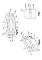
- FIG. 1Ais a perspective view of an exemplary embodiment of a T-PLIF implant
- FIG. 1Bis a partial top view, partial cross-sectional view of the T-PLIF implant shown in FIG. 1A ;
- FIG. 1Cis a cross-sectional of the T-PLIF implant shown in FIG. 1A ;
- FIG. 2Ais another perspective view of an exemplary embodiment of a T-PLIF implant
- FIG. 2Bis a top view of an exemplary embodiment of a T-PLIF implant shown in FIG. 2A ;
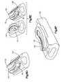
- FIG. 2Cis a perspective view depicting the first and second members of the exemplary embodiment of the T-PLIF implant shown in FIG. 2A ;
- FIG. 2Dis another perspective view depicting the first and second members of the exemplary embodiment of the T-PLIF implant shown in FIG. 2A ;
- FIG. 3Ais a perspective view of an exemplary embodiment of a second member of an exemplary embodiment of a T-PLIF implant
- FIG. 3Bis a perspective view of an exemplary embodiment of a first member of an exemplary embodiment of a T-PLIF implant
- FIG. 3Cis another perspective view of the second member shown in FIG. 3A ;
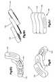
- FIG. 4Ais a perspective view of another exemplary embodiment of a T-PLIF implant
- FIG. 4Bis a cross-sectional view of the T-PLIF implant shown in FIG. 4A ;
- FIG. 5is a schematic representation of another exemplary embodiment of a T-PLIF implant
- FIG. 6Adepicts one or more steps for manufacturing an exemplary embodiment of a T-PLIF implant in accordance with one aspect of the present invention
- FIG. 6Bdepicts one or more steps for manufacturing an exemplary embodiment of a T-PLIF implant in accordance with one aspect of the present invention
- FIG. 6Cdepicts one or more steps for manufacturing an exemplary embodiment of a T-PLIF implant in accordance with one aspect of the present invention
- FIG. 6Ddepicts one or more steps for manufacturing an exemplary embodiment of a T-PLIF implant in accordance with one aspect of the present invention
- FIG. 6Edepicts one or more steps for manufacturing an exemplary embodiment of a T-PLIF implant in accordance with one aspect of the present invention
- FIG. 6Fdepicts one or more steps for manufacturing an exemplary embodiment of a T-PLIF implant in accordance with one aspect of the present invention
- FIG. 6Gdepicts one or more steps for manufacturing an exemplary embodiment of a T-PLIF implant in accordance with one aspect of the present invention
- FIG. 6Hdepicts one or more steps for manufacturing an exemplary embodiment of a T-PLIF implant in accordance with one aspect of the present invention
- FIG. 6Idepicts one or more steps for manufacturing an exemplary embodiment of a T-PLIF implant in accordance with one aspect of the present invention
- FIG. 6Jdepicts one or more steps for manufacturing an exemplary embodiment of a T-PLIF implant in accordance with one aspect of the present invention
- FIG. 7is a perspective view of an exemplary embodiment of a PLIF implant
- FIG. 8Ais another perspective view of the PLIF implant shown in FIG. 7 ;
- FIG. 8Bis another perspective view of the PLIF implant shown in FIG. 7 ;
- FIG. 8Cis a perspective view depicting the first and second members of the PLIF implant shown in FIG. 7 ;
- FIG. 9Ais a perspective view of an exemplary embodiment of a PLIF implant
- FIG. 9Bis a top view of the PLIF implant shown in FIG. 9A ;
- FIG. 9Cis a side view of the PLIF implant shown in FIG. 9A .
- an intervertebral implantfor insertion between adjacent vertebral bodies to restore vertebrae spacing
- the implantis sized and configured for use as an intervertebral spacer in a spinal fusion surgery, wherein an affected disk is removed from between two adjacent vertebrae and replaced with the implant.
- the implantpreferably provides segmental stability and allows for bone to grow in-between the two adjacent vertebrae to bridge the gap created by disk removal.
- the intervertebral implantmay be made from two or more pieces of allograft bone.
- the inventionmay have other applications and uses and should not be limited to the structure or use described and illustrated.
- the intervertebral implantmay include two or more pieces of allograft bone joined together by way of, for example, a dovetail joint.
- the dovetail jointis sized and configured to substantially follow at least a portion of the exterior shape or surface (e.g. perimeter) of the intervertebral implant.
- the dovetail jointis preferably sized and configured to substantially follow two or three surfaces of the implant such as, for example, the curved front and back surfaces of the implant or the curved front and back surfaces and one of the end surfaces of the implant.
- the intervertebral implantmay also include one or more bone pins for joining the allograft pieces.
- the intervertebral implantmay also include one or more through-bores for receiving ostegenic or bone graft material.
- the intervertebral implantis preferably sized and configured for insertion during a T-PLIF procedure.
- the intervertebral implantmay be sized and configured for insertion during a PLIF procedure.
- the T-PLIF implant 10may include a curved body 20 .
- the body 20may include a curved front surface 22 , a curved back surface 24 , a pair of narrow ends 26 , 28 separating the curved front and back surfaces 22 , 24 , an upper surface 30 and a lower surface 32 .
- the upper and lower surfaces 30 , 32are preferably sized and configured to contact at least a portion of the endplates of the adjacent vertebral bodies.
- the T-PLIF implant 10may take on various other profiles and exterior geometries, depending on the area of the spine to be treated.
- the curved front and back surfaces 22 , 24facilitate the offset insertion of the T-PLIF implant 10 through the narrow transforaminal window and into the disk space.
- the narrow ends 26 , 28may be rounded (as shown) or blunt.
- the upper and lower surfaces 30 , 32may include projections 33 , such as, for example, a plurality of teeth 34 for engaging the adjacent vertebrae.
- the projections 33 formed on the upper and lower surfaces 30 , 32preferably provide a mechanical connection between the T-PLIF implant 10 and the end plates by penetrating at least a portion of the end plates.
- the T-PLIF implant 10may include other forms of projections 33 aside from teeth 34 including, for example, ridges, grooves, threads, etc.
- the T-PLIF implant 10may also include one or more channels 36 .
- the channel 36extends from one of the ends 26 , 28 of the T-PLIF implant 10 (shown as end 26 ).
- the channel 36is preferably sized and configured to engage a surgical instrument, such as an implant holder.
- the T-PLIF implant 10is formed with at least two channels 36 , one on each of the front and back surfaces 22 , 24 .
- the channels 36being sized and configured with a curved surface to substantially follow the curved surfaces of the front and back surfaces 22 , 24 . It should be noted however that the T-PLIF implant 10 may be configured with a single channel 36 formed on only one of the surfaces 22 , 24 thereof.
- the channel 36may be formed on the upper and/or lower surfaces 30 , 32 of the T-PLIF implant 10 , or any other surface thereof.
- the T-PLIF implant 10may be configured without channels altogether.
- Other methods for engaging the T-PLIF implant 10 with surgical instrumentssuch as a threaded hole for receiving the threaded end of a surgical tool or a non-threaded hole for receiving an expandable head of an insertion tool, may also be used.
- the T-PLIF implant 10may be constructed from two or more pieces. This multi-piece configuration may be particularly useful for implants formed of allograft bone, since it may be difficult and/or impractical to obtain a single, sufficiently large piece of allograft for some applications.
- the T-PLIF implant 10may be formed by a first member 50 and a second member 80 . Although the T-PLIF implant 10 may be formed from more or less pieces.
- the first member 50may be joined to the second member 80 by any means. Preferably, the first member 50 is joined to the second member 80 by a dovetail joint.
- the first member 50may include a recess 55 formed therein, the recess 55 being sized and configured to receive a projection 82 formed on and extending from the second member 80 .
- the recess 55 and projection 82may take on any form.
- the projection 82may include a base surface 83 , two outwardly tapered side surfaces 84 , 85 extending from the base surface 83 and a substantially planar surface 86 . As shown, the cross sectional area of the projection 82 may become larger as the distance of the projection 82 from the base surface 83 increases.
- the recess 55similarly may include a base surface 55 a and two inwardly tapered side surfaces 56 , 58 extending from the base surface 55 a . As shown, the cross sectional area of the recess 55 may become smaller as the distance of the recess 55 from the base surface 55 a increases.
- the size and configuration of the tapered surfaces 56 , 58 formed on the first member 50being sized and configured to receive the tapered side surfaces 84 , 85 of the projection 82 so that, as will be generally appreciated by one of ordinary skill in the art, a dovetail joint is formed.
- the dovetail jointenables the first and second members 50 , 80 to slide with respect to one another, preferably the first and second members 50 , 80 slide substantially along the longitudinal axis 11 of the implant 10 , while substantially resisting the first and second members 50 , 80 from vertically separating.
- the recess 55 and the projection 82are formed so that they have a curved shape that substantially corresponds with the curved shape of the T-PLIF implant 10 .
- the dovetail jointhas a curved surface that substantially follows, at least, the contours of the curved front and back surfaces 22 , 24 .
- the inwardly tapered surfaces 56 , 58 of the recess 55may be machined in the first member 50 along the front surface 22 , the back surface 24 , and one of the narrow ends (shown here as 28 ).
- the recess 55may be opened at one of the narrow ends (shown here as 26 ) thus forming an entry space 59 for slidably receiving the projection 82 . In this manner, the recess 55 can slidably receive the projection 82 formed on the second member 80 along the longitudinal axis 11 of the implant 10 .
- the entry space 59may be formed with a slightly larger opening to facilitate easier insertion of the projection 82 into the recess 55 .
- the recess 55may become more narrow towards the rear of the dovetail joint (towards end 28 ) so that the first and second members 50 , 80 can be slid together easily but the dovetail joint becomes tighter as its final position is reached.
- the recess 55may have the same dimension throughout.
- the first and second members 50 , 80are sized and configured within sufficient tolerance so that once the projection 82 is fully inserted into the recess 55 the first and second members 50 , 80 resist separation of the first and second members 50 , 80 .
- first and second members 50 , 80may be sized and configured so that when the projection 82 is fully inserted into the recess 55 , a press-fit type connection is achieved. While it has been described and shown as if the projection 82 is slidably receivable within the recess 55 via one of the narrow ends 26 , 28 it should be understood that the projection 82 may be slidably receivable into the recess 55 via one of the front and/or back surfaces 22 , 24 , or any other surface thereof.
- the second member 80is preferably sized and configured so that once fully inserted into the first member 50 , the outer surface of the implant 10 is substantially smooth and devoid of any gap formed by the dovetail joint.
- the second member 80may include a ledge 88 (as best shown in FIG. 2D ) formed on an end thereof, the ledge 88 being sized and configured to cover the entry space 59 of the recess 55 .
- the T-PLIF implant 10may also include one or more pins 62 for securing the first and second members 50 , 80 , as best shown in FIGS. 2A-2D .
- the pins 62may take on any configuration including but not limited to circular, elliptical, oval, square, rectangular, star shaped, etc.
- the pins 62may be secured within the implant 10 in a variety of ways, preferably, the T-PLIF implant 10 may include one or more holes 64 for receiving the pins 62 .
- the pins 62 and respective holes 64may be sized so that they extend from the upper surface 30 to the lower surface 32 .
- the pins 62 and respective holes 64may be sized so that they extend only through a portion of the height of the implant 10 .
- the pins 62may be secured within the corresponding holes 64 by any means including but not limited to press-fit, adhesive, mechanical connection such as, for example, threaded connection, etc.
- the T-PLIF implant 10may incorporate substantially straight pins 62 . More preferably, by incorporating a joint, such as, for example, a dovetail joint that resists vertical separation of the first and second members with respect to one another, the pins 62 may extend substantially vertical and/or perpendicular with respecting to the interfacing surface of the joint. The pins 62 may intersect the interfacing surface of the joint at an angle ⁇ acute over ( ⁇ ) ⁇ , preferably at a substantially ninety-degree angle with respect to the interfacing surface of the joint.
- ⁇ acute over ( ⁇ ) ⁇preferably at a substantially ninety-degree angle with respect to the interfacing surface of the joint.
- substantially straight vertical pins 62facilitates maximum resistance against the first and second members 50 , 80 from sliding apart and enables one or more vertical through-bores 60 to be formed in the implant 10 , the through-bore 60 being sized and configured to receive bone graft material to facilitate bone fusion of the adjacent vertebrae bodies.
- the implant 10includes at least two substantially straight vertical pins 62 , one on either side of the through-bore 60 , adjacent the ends 26 , 28 of the implant 10 .
- the pins 62will be as far apart as possible to maximize the size of the vertical through-bore 60 .
- a larger through-bore 60may allow the surgeon to pack additional bone graft and other bone growth inducing material into the implant 10 .
- the number, location and/or orientation of the pins 62can be varied, for example, one, three or more pins 62 may also be used. Additionally, the pins 62 may be placed obliquely or at an angle with respect to the interfacing surface of the joint.
- the T-PLIF implant 10may alternatively include two or more vertical through-bores 60 extending from the upper surface 30 to the lower surface 32 of the implant 10 .
- the T-PLIF implant 10may include one or more horizontal bores (not shown). The horizontal bores may extend from the back surface 22 to the front surface 24 or from one or both of the ends 26 , 28 .
- the implant 10may not include any bores, vertical or horizontal.
- the T-PLIF implant 10has been generally described as incorporating a first member 50 and a second member 80 , wherein the first and second members 50 , 80 are located one on top of the other, it should be understood that, as best shown in FIGS. 4A and 4B , the first and second members 50 , 80 may be arranged in a side by side configuration. As shown in this configuration, the T-PLIF implant 10 may include a substantially straight dovetail configuration extending from the upper surface 30 to the lower surface 32 . Moreover, as best shown in FIG. 4B the pins 62 may be generally oriented perpendicular to the dovetail joints. Alternatively, the pins 62 may be oriented at an acute angle ⁇ with respect to the longitudinal axis 11 of the implant 10 .
- the T-PLIF implant 10has been described as being formed from first and second members 50 , 80 , it should be understood that the T-PLIF implant 10 may include three or more pieces and/or members. As best shown in FIG. 5 , for example, the T-PLIF implant 100 may be formed from a first member 130 , a second member 135 and a third member 140 . As best shown in FIGS. 6G-6J , the first and second members 130 , 135 may be formed with projections 82 , while the third member 140 may be formed with a pair of recesses 55 for engaging the projections 82 formed on the first and second members 130 , 135 .
- the third member 140may be formed with a pair of projections 82 and the first and second members 130 , 135 may be formed with recesses 55 for securing the projections 82 .
- the third member 140may be formed with both a projection 82 and a recess 55 while one of the first and second members 130 , 135 may be formed with a recess 55 for engaging the projection 82 formed on the third member 140 .
- the other of the first and second members 130 , 135being formed with a projection 82 for engaging with the recess 55 formed on the third member 140 .
- the orientation of the membersmay be provided in any appropriate combination.
- the dimensions of the T-PLIF implant 10can be varied to accommodate a patient's anatomy.
- the length of the T-PLIF implant 10as generally measured by the distance between the ends 26 , 28 of the implant 10 , may range from about 26 mm to about 33 mm.
- the width of the T-PLIF implant 10as generally measured by the distance between the front and back surfaces 22 , 24 , may range from about 9 mm to about 12 mm.
- implants having footprints of, for example, 10 mm ⁇ 27 mm, 10 mm ⁇ 30 mm, 10 mm ⁇ 33 mm, 12 mm ⁇ 27 mm, 12 mm ⁇ 30 mm, and 12 mm ⁇ 33 mmmay be possible.
- the height of the T-PLIF implant 10is generally chosen based on the size of the disk space to be filled.
- the height of the T-PLIF implant 10is greatest at the mid-section between the two narrow ends 26 , 28 and tapers gradually along the longitudinal axis 11 of the implant 10 so that it is thinnest at the narrow ends 26 , 28 of the implant 10 .
- the taperis preferably curved and provides a convex configuration for a better anatomical fit, while also facilitating insertion of the implant 10 into the affected disc space.
- the T-PLIF implant 10may have a height at its mid-section of about 7.0 mm to about 17.0 mm.
- the height at the ends 26 , 28 of the T-PLIF implant 10may range from about 1.5 mm to about 2.0 mm less than the height at the mid-section. Alternatively, the height of the T-PLIF implant 10 may remain substantially constant throughout the implant 10 .
- the height of the T-PLIF implant 10preferably does not taper or change along the shorter axis 12 (e.g. axis transverse to the longitudinal axis 11 ) of implant 10 . Thus for any given cross section taken perpendicular to the longitudinal axis 11 of the implant 10 , the distance between the upper and lower surfaces 30 , 32 remains substantially constant. Alternatively, the height of the implant 10 may change or taper along the shorter axis 12 of implant 10 .
- the T-PLIF implant 10may be about 30 mm in length.
- the radius of curvature of the front surface 22may be about 19 mm.
- the radius of curvature for the back surface 24may be about 29 mm.
- the length of the through-bore 60may be about 15.5 mm.
- the length between the holes 64may be about 20 mm.
- the diameter of the holes 64may be about 2.4 mm.
- the T-PLIF implantis preferably sized and configured for insertion in-between adjacent vertebra via a T-PLIF procedure which generally involves a posterior approach, offset from a midline of the spine, to the affected intervertebral disk space.
- a narrow transforaminal windowmay be produced to permit insertion of the T-PLIF implant.
- the transforaminal windowis generally limited laterally by the patient's dura and the superior exiting nerve root.
- the T-PLIF procedureenables the T-PLIF implant to be seated in the disc space behind the dura without disturbing the anterior curtain of the disc space.
- One exemplary surgical technique for the T-PLIF procedurebegins with the patient being placed in a prone position on a lumbar frame. Next, radiographic equipment may be used to assist the surgeon in locating the precise intraoperative position for the T-PLIF implant. Next, an incision may be made. Following incision, the facets, lamina and other anatomical landmarks are identified. The affected vertebrae are then preferably distracted using a lamina spreader or a lateral distractor, both of which are commonly known in the art.
- the transforaminal windowis preferably created by removing the inferior facet of the cranial vertebrae and the superior facet of the caudal vertebrae using, for example, one or more osteotomes.
- a discectomymay then be performed during which a portion of, substantially all of, and more preferably all, of the disc material from the affected disc space may be removed using a combination of straight and angled curettes.
- the superficial layers of the entire cartilaginous endplatesmay be removed with a combination of straight and angled bone rasps. This is done to expose bleeding bone, but care should be taken to avoid excess removal of subchondral bone, as this may weaken the anterior column. Entire removal of the endplate may result in subsidence and loss of segmental stability.
- an appropriately sized trial-fit T-PLIF spacermay be inserted into the intervertebral disc space using gentle impaction, to determine the appropriate height of the T-PLIF implant for the disc space to be filled. Fluoroscopy can assist in confirming the fit of the trial spacer. Upon identifying and removing the best fitting trial spacer, a T-PLIF implant of appropriate size is selected.
- bone graft materialsuch as autogenous cancellous bone or a bone substitute
- the T-PLIF implantis preferably formed with a through bore, bone graft material may be inserted into the through-bore.
- the T-PLIF implantmay come pre-arrived with bone graft material packed therein.
- the T-PLIF implantmay be held securely using a surgical instrument such as an implant holder, which may engage the channels formed in or other features in the T-PLIF implant.
- the tips of the implant holdermay be curved or angled to mate with the curved implant and to facilitate insertion of the implant into the disc space.
- the T-PLIF implantmay then be introduced into the intervertebral disc space via the transforaminal window.
- a guide tool having a curved blade which preferably matches the curvature of the anterior face of T-PLIF implantmay be used to properly guide the T-PLIF implant into the affected disc space. Slight impaction may also be necessary.
- the implant holder and optional guide toolare removed and additional bone graft material may be inserted in the anterior and lateral aspects of the affected disc space.
- the T-PLIF implantshould be recessed from the anterior edge of the vertebral body.
- the curvature of the anterior face of the implantis substantially the same as the curvature of the anterior edge of the disc space.
- the intervertebral implantmay be sized and configured for insertion during a PLIF procedure.
- the PLIF implant 200may include a body 210 , the body 210 may include an anterior surface 260 , a posterior surface 280 , a pair of lateral side surfaces 220 , 240 , an upper surface 300 and a lower surface 320 .
- the upper and lower surfaces 300 , 320are preferably sized and configured to contact at least a portion of the endplates of the adjacent vertebral bodies.
- the PLIF implant 200may take on various profiles and exterior geometries, depending on the area of the spine to be treated.
- the upper and lower surfaces 300 , 320may include projections 340 , such as, for example, a plurality of teeth 342 for engaging the adjacent vertebrae.
- the projections 340 formed on the upper and lower surfaces 300 , 320preferably provide a mechanical connection between the PLIF implant 200 and the end plates by penetrating at least a portion of the end plates.
- the initial mechanical stability afforded by incorporation of the projections 340 , and in particular the teeth 342minimizes the risk of post-operative expulsion and/or slippage of the PLIF implant 200 .
- the PLIF implant 200may also include one or more channels 360 .
- the channels 360are formed in one or both of the lateral side surfaces 220 , 240 and extend from the posterior surface 280 of the T-PLIF implant 200 .
- the channel 360is preferably sized and configured to engage a surgical instrument, such as an implant holder.
- the PLIF implant 200is formed with at least two channels 360 , one on each of the lateral side surfaces 220 , 240 . It should be noted however that the PLIF implant 200 may be configured with a single channel 360 formed on only one surface thereof. Alternatively, the channel 360 may be formed on the upper and/or lower surfaces 300 , 320 of the PLIF implant 200 , or any other surface thereof.
- the PLIF implant 200may be configured without channels altogether.
- Other methods for engaging the PLIF implant 200 with surgical instrumentssuch as, for example, a threaded hole for receiving the threaded end of a surgical tool or a non-threaded hole for receiving an expandable head of an insertion tool, may also be used.
- the PLIF implant 200may be constructed from two or more pieces. This multi-piece configuration may be particularly useful for implants formed of allograft bone, since it may be difficult and/or impractical to obtain a single, sufficiently large piece of allograft for some applications.
- the PLIF implant 200may be formed by a first member and a second member. The first member may be joined to the second member by any means. Preferably, the first member is joined to the second member by a dovetail joint. Alternatively, the PLIF implant 200 may contain more or less pieces and/or members. For example, as best shown in FIGS. 8A-8C and 9 A- 9 C, the PLIF implant 200 may be formed by a first member 500 , a second member 600 and a third member 700 . The second member 600 may be joined to the first and third members 500 , 700 by any means. Preferably, the second member 600 is joined to the first and third members 500 , 700 by dovetail joints.
- the first, second and third members 500 , 600 , 700may each include one or more projections 820 , one or more recesses 550 , and/or one or more projections 820 and recesses 550 for interconnecting with one another. Any combination of recesses 550 and projections 820 may be used.
- the recess 550 and projection 820may take on any form.
- the recess 550may include two inwardly tapered side surfaces for slidably receiving two outwardly tapered side surfaces formed on the projection 820 , as previously described in connection with the T-PLIF implant 10 .
- the dovetail jointis sized and configured to permit the first, second and third members 500 , 600 , 700 to slide with respect to one another substantially along an axis 202 transverse to the longitudinal axis 201 of the implant 200 , while substantially resisting the members 500 , 600 , 700 from vertically separating.
- the PLIF implant 200may include a dovetail configuration that substantially follows the contours of the body 210 , for example, the contours of the lateral sides surfaces 220 , 240 , of the PLIF implant 200 as described above in connection with the T-PLIF implant 10 .
- the PLIF implant 200may also include one or more pins 620 (similar to pins 62 described above) for further securing the first, second and third members 500 , 600 , 700 together.
- the PLIF implant 200may incorporate substantially straight pins 620 . More preferably, by incorporating a joint, such as, for example, a dovetail joint that resists vertical separation of the first, second and third members 500 , 600 , 700 with respect to one another, the pins 620 may extend substantially vertical and/or perpendicular with respect to the interfacing surface of the joint.
- the pins 620may intersect the interfacing surface of the joint at an angle ⁇ acute over ( ⁇ ) ⁇ , preferably at a substantially ninety-degree angle with respect to the interfacing surface of the joint.
- substantially straight vertical pins 620facilitates maximum resistance against the first, second, and third members 500 , 600 , 700 from sliding apart and enables one or more vertical through-bores 900 to be formed in the implant 200 , the bore 900 being sized and configured to receive bone graft material to facilitate bone fusion of the adjacent vertebrae bodies.
- the implant 200includes at least one substantially straight pin 620 .
- the pincan be located anywhere on the implant 200 .
- the pin 620will be located so as to maximize the size of the vertical through-bore 900 .
- a larger through-bore 900may allow the surgeon to pack the PLIF implant 200 with more bone graft and other bone growth inducing material.
- the pin 620may be located near the anterior surface 280 of the implant 200 .
- the number, location and/or orientation of the pins 620can be varied, for example, two or more pins 620 may be used. Additionally, the pins 62 may be placed obliquely or at an angle with respect to the interfacing surface of the joint.
- the PLIF implant 200may alternatively include two or more vertical through-bores 900 extending from the upper surface 300 to the lower surface 320 of the implant 200 .
- the PLIF implant 200may include one or more horizontal bores (not shown). The horizontal bores may extend from one or both of the lateral side surfaces 220 , 240 or from one or both of the posterior and anterior surfaces 260 , 280 .
- the implant 200may not include any through bores, either vertical or horizontal.
- the dimensions of the PLIF implant 200can be varied to accommodate a patient's anatomy.
- the length of the PLIF implant 200as generally measured by the distance from the anterior surface to the posterior surface, may range from about 18 mm to about 32 mm.
- the width of the PLIF implant 200as generally measured by the distance between the two lateral side surfaces, may range from about 6 mm to about 14 mm.
- the height of the PLIF implant 200is generally chosen based on the sized of the disk space to be filled.
- the height of the PLIF implant 200is greatest at the a point in between the mid-section and the anterior surface 260 and tapers gradually along the longitudinal axis 201 of the implant 200 so that it is thinnest at the posterior surface 260 of the implant 200 .
- the taperis preferably curved and provides a convex configuration for a better anatomical fit, while also facilitating insertion of the implant 200 into the affected disc space.
- the PLIF implant 200may have a height at its anterior surface of about 7 mm to about 17 mm and a height at its posterior surface of about 4.6 mm to about 13.7 mm. Alternatively, the height of the PLIF implant 200 may remain substantially constant throughout the implant 200 . The height of the PLIF implant 200 preferably does not taper or change along the shorter axis 202 of the PLIF implant 200 . Thus for any given cross section taken perpendicular to the longitudinal axis 201 of the PLIF implant 200 , the distance between the upper and lower surfaces 300 , 320 remains substantially constant. Alternatively, the height of the PLIF implant 200 may change or taper along the shorter axis 202 as well.
- the PLIF implantis preferably sized and configured for insertion in-between adjacent vertebra via a PLIF procedure which generally involves insertion of two PLIF implants via a posterior approach, on either side of a midline of the spine, to the affected intervertebral disk space.
- One exemplary surgical technique for the PLIF procedurebegins with the patient being placed in a prone position on a lumbar frame. Next, radiographic equipment may be used to assist the surgeon in locating the precise intraoperative position for the PLIF implant. Next, an incision may be made and the patient's skin may be dissected from the midline laterally. Following incision, the spinous process, lamina, dura, nerve roots, and other anatomical landmarks are identified. The affected vertebrae are then preferably distracted using a lamina spreader or a lateral distractor, both of which are commonly known in the art. The surgeon may then perform a laminotomy to the medial aspect of the facet and reflects dura to expose a small window (e.g.
- a discectomymay be performed during which substantially all of, and more preferably all, of the disc material from the affected disc space may be removed through the window.
- the superficial layers of the entire cartilaginous endplatesmay be removed. This is done to expose bleeding bone, but care should be taken to avoid excess removal of subchondral bone, as this may weaken the anterior column. Entire removal of the endplate may result in subsidence and loss of segmental stability.
- an appropriately sized trial-fit PLIF spacermay be inserted into the intervertebral disc space using gentle impaction, to determine the appropriate height of the PLIF implant for the disc space to be filled. Fluoroscopy can assist in confirming the fit of the trial spacer. Upon identifying and removing the best fitting trial spacer, a PLIF implant of appropriate size is selected.
- bone graft materialsuch as autogenous cancellous bone or a bone substitute
- the PLIF implantis preferably formed with a through bore, bone graft material may be inserted into the through-bore.
- the PLIF implantmay come pre-arrived with bone graft material packed therein.
- the PLIF implantmay be held securely using a surgical instrument such as an implant holder, which may engage the channels or slots formed on the PLIF implant.
- the first PLIF implantmay then be introduced into the intervertebral disc space.
- autogenous cancellous bone or a bone substituteshould be placed in the anterior and medial aspect of the vertebral disc space prior to placement of the second PLIF implant.
- the distractormay then be removed and a second PLIF implant of the same height as the first PLIF implant may be inserted into the space, using gentle impaction as before.
- the implantsare recessed 2-4 mm beyond the posterior rim of the vertebral body.
- T-PLIF and PLIF implantsmay be inserted using minimally invasive procedures.
- FIGS. 6A-6Jan exemplary method for manufacturing a multi-piece allograft implant will now be described and shown in connection with the T-PLIF implant.
- the PLIF implantmay be similarly manufactured.
- the members, such as, for example, the first and second members 50 , 80 or the first, second and third members 130 , 135 , 140 , of the implantmay be individually formed (e.g. machined, sized, shaped, etc.) before assembling the T-PLIF implant.
- the individual membersmay be first roughly shaped on the pre-selected bone 150 , which may have been obtained, for example, from a cadaver.
- the individual members of the implantmay be oriented such that the Haversian canals of each bone portion 150 may be substantially aligned to be roughly perpendicular to the upper and lower surfaces of the implant. This orientation of the bone portions 150 may provide an implant having maximum strength in the vertical direction. This orientation of the bone portions 150 may also provide the benefit of readily allowing blood and/or osteogenic materials to flow through the canals between the vertebral end plates, thus facilitating fusion of the implant with the adjacent vertebrae.
- the individual membersAfter forming the individual members into their desired shapes, the desired shape including forming one of either the recess or projection portion of a dovetail joint, the individual members may be removed and/or dislodged from the pre-selected bone 150 . Next, the individual members may be assembled by sliding together, via the dovetail joint, to create the implant as shown in FIGS. 6D-J .
- one or more holesmay be formed in the implant.
- the holesbeing sized and configured to receive one or more pins.
- the holesmay be formed before the individual members have been assembled into the implant.
- one or more through boresmay be formed in the implant.
- the through boresbeing sized and configured to receive bone graft material for facilitating spinal fusion.
- the boresmay be formed before the individual members have been assembled into the implant.
- the projections and/or teethmay be formed into the upper and lower surfaces of the implant.
- the teethmay be formed into the upper and lower surfaces of the implant before assembly.
- one or more channelsmay be formed for receiving the implant holder. This step may also occur before or after assembling the implant.
- the individual members of the implantbefore assembling the implant, in particular by shaping the outer shape or surface (e.g. perimeter) of the implant into the base tissue and then joining the members of the intervertebral implant, the following advantages may be achieved.
- individually forming the individual membersmay allow for a larger material footprint. This may be especially important when forming implants from allograft bone due to limitations of material thicknesses in available base allograft tissue.
- the individual machining of the dovetail geometrypermits one to better control the required complex tool path. For example, by individually forming the members the user has better control over forming and/or shaping the outer shape or surface (e.g. perimeter) of the implant and the curved dovetail joint.
- individually forming the members prior to assemblymay result in greater size potential of the graft and better control over forming the complex, geometries of the implant and dovetail feature.
- any or all of the components described hereinsuch as, for example, individual members, pins, etc. may be provided in sets or kits so that the surgeon may select various combinations of components to perform a fixation procedure which is configured specifically for the particular needs/anatomy of a patient. It should be noted that one or more of each component may be provided in a kit or set. In some kits or sets, the same component may be provided in different shapes and/or sizes.
Landscapes
- Health & Medical Sciences (AREA)
- Engineering & Computer Science (AREA)
- Biomedical Technology (AREA)
- Orthopedic Medicine & Surgery (AREA)
- Transplantation (AREA)
- Neurology (AREA)
- Heart & Thoracic Surgery (AREA)
- Oral & Maxillofacial Surgery (AREA)
- Cardiology (AREA)
- Vascular Medicine (AREA)
- Life Sciences & Earth Sciences (AREA)
- Animal Behavior & Ethology (AREA)
- General Health & Medical Sciences (AREA)
- Public Health (AREA)
- Veterinary Medicine (AREA)
- Physical Education & Sports Medicine (AREA)
- Prostheses (AREA)
Abstract
Description
Claims (33)
Priority Applications (4)
| Application Number | Priority Date | Filing Date | Title |
|---|---|---|---|
| US11/854,132US8128700B2 (en) | 2006-09-13 | 2007-09-12 | Allograft intervertebral implant and method of manufacturing the same |
| US13/359,674US8460389B2 (en) | 2006-09-13 | 2012-01-27 | Allograft intervertebral implant and method of manufacturing the same |
| US13/633,333US8579980B2 (en) | 2006-09-13 | 2012-10-02 | Allograft intervertebral implant and method of manufacturing the same |
| US14/049,534US8926701B2 (en) | 2006-09-13 | 2013-10-09 | Allograft intervertebral implant and method of manufacturing the same |
Applications Claiming Priority (2)
| Application Number | Priority Date | Filing Date | Title |
|---|---|---|---|
| US84451506P | 2006-09-13 | 2006-09-13 | |
| US11/854,132US8128700B2 (en) | 2006-09-13 | 2007-09-12 | Allograft intervertebral implant and method of manufacturing the same |
Related Child Applications (1)
| Application Number | Title | Priority Date | Filing Date |
|---|---|---|---|
| US13/359,674ContinuationUS8460389B2 (en) | 2006-09-13 | 2012-01-27 | Allograft intervertebral implant and method of manufacturing the same |
Publications (2)
| Publication Number | Publication Date |
|---|---|
| US20080082173A1 US20080082173A1 (en) | 2008-04-03 |
| US8128700B2true US8128700B2 (en) | 2012-03-06 |
Family
ID=39261999
Family Applications (4)
| Application Number | Title | Priority Date | Filing Date |
|---|---|---|---|
| US11/854,132Active2030-12-06US8128700B2 (en) | 2006-09-13 | 2007-09-12 | Allograft intervertebral implant and method of manufacturing the same |
| US13/359,674ActiveUS8460389B2 (en) | 2006-09-13 | 2012-01-27 | Allograft intervertebral implant and method of manufacturing the same |
| US13/633,333ActiveUS8579980B2 (en) | 2006-09-13 | 2012-10-02 | Allograft intervertebral implant and method of manufacturing the same |
| US14/049,534ActiveUS8926701B2 (en) | 2006-09-13 | 2013-10-09 | Allograft intervertebral implant and method of manufacturing the same |
Family Applications After (3)
| Application Number | Title | Priority Date | Filing Date |
|---|---|---|---|
| US13/359,674ActiveUS8460389B2 (en) | 2006-09-13 | 2012-01-27 | Allograft intervertebral implant and method of manufacturing the same |
| US13/633,333ActiveUS8579980B2 (en) | 2006-09-13 | 2012-10-02 | Allograft intervertebral implant and method of manufacturing the same |
| US14/049,534ActiveUS8926701B2 (en) | 2006-09-13 | 2013-10-09 | Allograft intervertebral implant and method of manufacturing the same |
Country Status (1)
| Country | Link |
|---|---|
| US (4) | US8128700B2 (en) |
Cited By (71)
| Publication number | Priority date | Publication date | Assignee | Title |
|---|---|---|---|---|
| US20080234741A1 (en)* | 2007-01-19 | 2008-09-25 | Landry Michael E | Artificial functional spinal unit system and method for use |
| US20110276142A1 (en)* | 2008-10-13 | 2011-11-10 | Marcin Niemiec | Articulating Spacer |
| US20110319999A1 (en)* | 2010-06-24 | 2011-12-29 | O'neil Michael J | Lateral Spondylolisthesis Reduction Cage |
| US20120071978A1 (en)* | 2010-06-29 | 2012-03-22 | Jann-Paul Suedkamp | Distractible intervertebral implant |
| US20130110247A1 (en)* | 2011-11-01 | 2013-05-02 | Amedica Corporation | Implants with a Connectable Insert and Related Systems and Methods |
| US20140296983A1 (en)* | 2013-03-12 | 2014-10-02 | Coorstek Medical Llc D/B/A Imds | Fusion Cage |
| US8926701B2 (en) | 2006-09-13 | 2015-01-06 | DePuy Synthes Products, LLC | Allograft intervertebral implant and method of manufacturing the same |
| USD731061S1 (en) | 2012-11-28 | 2015-06-02 | Nuvasive, Inc. | Intervertebral implant |
| US9192419B2 (en) | 2008-11-07 | 2015-11-24 | DePuy Synthes Products, Inc. | Zero-profile interbody spacer and coupled plate assembly |
| US9216096B2 (en) | 2010-03-16 | 2015-12-22 | Pinnacle Spine Group, Llc | Intervertebral implants and related tools |
| US9220604B2 (en) | 2010-12-21 | 2015-12-29 | DePuy Synthes Products, Inc. | Intervertebral implants, systems, and methods of use |
| US9226764B2 (en) | 2012-03-06 | 2016-01-05 | DePuy Synthes Products, Inc. | Conformable soft tissue removal instruments |
| US9241809B2 (en) | 2010-12-21 | 2016-01-26 | DePuy Synthes Products, Inc. | Intervertebral implants, systems, and methods of use |
| US9380932B1 (en) | 2011-11-02 | 2016-07-05 | Pinnacle Spine Group, Llc | Retractor devices for minimally invasive access to the spine |
| US9463097B2 (en) | 2003-02-06 | 2016-10-11 | DePuy Synthes Products, Inc. | Intervertebral implant |
| US9468536B1 (en) | 2011-11-02 | 2016-10-18 | Nuvasive, Inc. | Spinal fusion implants and related methods |
| US9492288B2 (en) | 2013-02-20 | 2016-11-15 | Flexuspine, Inc. | Expandable fusion device for positioning between adjacent vertebral bodies |
| US20160331542A1 (en)* | 2015-05-14 | 2016-11-17 | Globus Medical, Inc. | Expandable intervertebral implants and methods of installation thereof |
| US9517144B2 (en) | 2014-04-24 | 2016-12-13 | Exactech, Inc. | Limited profile intervertebral implant with incorporated fastening mechanism |
| US9526627B2 (en) | 2011-11-17 | 2016-12-27 | Exactech, Inc. | Expandable interbody device system and method |
| US9572681B2 (en) | 2002-02-19 | 2017-02-21 | DePuy Synthes Products, Inc. | Intervertebral implant |
| US9579124B2 (en) | 2003-08-05 | 2017-02-28 | Flexuspine, Inc. | Expandable articulating intervertebral implant with limited articulation |
| US9744049B2 (en) | 2007-11-16 | 2017-08-29 | DePuy Synthes Products, Inc. | Low profile intervertebral implant |
| US9788971B1 (en) | 2013-05-22 | 2017-10-17 | Nuvasive, Inc. | Expandable fusion implant and related methods |
| US9801734B1 (en) | 2013-08-09 | 2017-10-31 | Nuvasive, Inc. | Lordotic expandable interbody implant |
| US9867718B2 (en) | 2014-10-22 | 2018-01-16 | DePuy Synthes Products, Inc. | Intervertebral implants, systems, and methods of use |
| US9931224B2 (en) | 2009-11-05 | 2018-04-03 | DePuy Synthes Products, Inc. | Self-pivoting spinal implant and associated instrumentation |
| US9993349B2 (en) | 2002-06-27 | 2018-06-12 | DePuy Synthes Products, Inc. | Intervertebral disc |
| US10022245B2 (en) | 2012-12-17 | 2018-07-17 | DePuy Synthes Products, Inc. | Polyaxial articulating instrument |
| US10058433B2 (en) | 2012-07-26 | 2018-08-28 | DePuy Synthes Products, Inc. | Expandable implant |
| US10064737B2 (en) | 2015-12-07 | 2018-09-04 | Industrial Technology Research Institute | Implant device for osseous integration |
| US10070970B2 (en) | 2013-03-14 | 2018-09-11 | Pinnacle Spine Group, Llc | Interbody implants and graft delivery systems |
| US10195053B2 (en) | 2009-09-18 | 2019-02-05 | Spinal Surgical Strategies, Llc | Bone graft delivery system and method for using same |
| US10195816B2 (en) | 2014-12-01 | 2019-02-05 | Industrial Technology Research Institute | Metal/polymer composite material and method for fabricating the same |
| US10245159B1 (en) | 2009-09-18 | 2019-04-02 | Spinal Surgical Strategies, Llc | Bone graft delivery system and method for using same |
| US10398563B2 (en) | 2017-05-08 | 2019-09-03 | Medos International Sarl | Expandable cage |
| US10398565B2 (en) | 2014-04-24 | 2019-09-03 | Choice Spine, Llc | Limited profile intervertebral implant with incorporated fastening and locking mechanism |
| US10433977B2 (en) | 2008-01-17 | 2019-10-08 | DePuy Synthes Products, Inc. | Expandable intervertebral implant and associated method of manufacturing the same |
| US10463500B2 (en) | 2014-11-07 | 2019-11-05 | Industrial Technology Research Institute | Medical composite material, method for fabricating the same and applications thereof |
| US10512548B2 (en) | 2006-02-27 | 2019-12-24 | DePuy Synthes Products, Inc. | Intervertebral implant with fixation geometry |
| US10537436B2 (en) | 2016-11-01 | 2020-01-21 | DePuy Synthes Products, Inc. | Curved expandable cage |
| US10888433B2 (en) | 2016-12-14 | 2021-01-12 | DePuy Synthes Products, Inc. | Intervertebral implant inserter and related methods |
| US10940016B2 (en) | 2017-07-05 | 2021-03-09 | Medos International Sarl | Expandable intervertebral fusion cage |
| US10966843B2 (en) | 2017-07-18 | 2021-04-06 | DePuy Synthes Products, Inc. | Implant inserters and related methods |
| US10966840B2 (en) | 2010-06-24 | 2021-04-06 | DePuy Synthes Products, Inc. | Enhanced cage insertion assembly |
| WO2021067965A1 (en)* | 2019-10-04 | 2021-04-08 | Pain TEQ, LLC | Allograft implant for fusing a sacroiliac joint |
| US10973652B2 (en) | 2007-06-26 | 2021-04-13 | DePuy Synthes Products, Inc. | Highly lordosed fusion cage |
| US10973656B2 (en) | 2009-09-18 | 2021-04-13 | Spinal Surgical Strategies, Inc. | Bone graft delivery system and method for using same |
| US11020129B2 (en) | 2019-10-04 | 2021-06-01 | Pain TEQ, LLC | Drill-less method of fusing a sacroiliac joint |
| US11045331B2 (en) | 2017-08-14 | 2021-06-29 | DePuy Synthes Products, Inc. | Intervertebral implant inserters and related methods |
| US11058550B2 (en) | 2019-10-04 | 2021-07-13 | Pain TEQ, LLC | Allograft implant for fusing a sacroiliac joint |
| US11083511B2 (en) | 2013-03-15 | 2021-08-10 | Orthocision Inc. | Method and implant system for sacroiliac joint fixation and fusion |
| US11344424B2 (en) | 2017-06-14 | 2022-05-31 | Medos International Sarl | Expandable intervertebral implant and related methods |
| US11369490B2 (en) | 2011-03-22 | 2022-06-28 | DePuy Synthes Products, Inc. | Universal trial for lateral cages |
| US11426290B2 (en) | 2015-03-06 | 2022-08-30 | DePuy Synthes Products, Inc. | Expandable intervertebral implant, system, kit and method |
| US11426286B2 (en) | 2020-03-06 | 2022-08-30 | Eit Emerging Implant Technologies Gmbh | Expandable intervertebral implant |
| US11446156B2 (en) | 2018-10-25 | 2022-09-20 | Medos International Sarl | Expandable intervertebral implant, inserter instrument, and related methods |
| US11452607B2 (en) | 2010-10-11 | 2022-09-27 | DePuy Synthes Products, Inc. | Expandable interspinous process spacer implant |
| US11497618B2 (en) | 2006-12-07 | 2022-11-15 | DePuy Synthes Products, Inc. | Intervertebral implant |
| US11497619B2 (en) | 2013-03-07 | 2022-11-15 | DePuy Synthes Products, Inc. | Intervertebral implant |
| US11510788B2 (en) | 2016-06-28 | 2022-11-29 | Eit Emerging Implant Technologies Gmbh | Expandable, angularly adjustable intervertebral cages |
| US11596523B2 (en) | 2016-06-28 | 2023-03-07 | Eit Emerging Implant Technologies Gmbh | Expandable and angularly adjustable articulating intervertebral cages |
| US11602438B2 (en) | 2008-04-05 | 2023-03-14 | DePuy Synthes Products, Inc. | Expandable intervertebral implant |
| US11607321B2 (en) | 2009-12-10 | 2023-03-21 | DePuy Synthes Products, Inc. | Bellows-like expandable interbody fusion cage |
| US11612491B2 (en) | 2009-03-30 | 2023-03-28 | DePuy Synthes Products, Inc. | Zero profile spinal fusion cage |
| US11752009B2 (en) | 2021-04-06 | 2023-09-12 | Medos International Sarl | Expandable intervertebral fusion cage |
| US11850160B2 (en) | 2021-03-26 | 2023-12-26 | Medos International Sarl | Expandable lordotic intervertebral fusion cage |
| US11931053B2 (en) | 2022-08-04 | 2024-03-19 | PTL Opco, LLC | Single-use joint decorticator apparatus |
| USRE49973E1 (en) | 2013-02-28 | 2024-05-21 | DePuy Synthes Products, Inc. | Expandable intervertebral implant, system, kit and method |
| US12090064B2 (en) | 2022-03-01 | 2024-09-17 | Medos International Sarl | Stabilization members for expandable intervertebral implants, and related systems and methods |
| US12440346B2 (en) | 2023-03-31 | 2025-10-14 | DePuy Synthes Products, Inc. | Expandable intervertebral implant |
Families Citing this family (108)
| Publication number | Priority date | Publication date | Assignee | Title |
|---|---|---|---|---|
| AU2004212942A1 (en) | 2003-02-14 | 2004-09-02 | Depuy Spine, Inc. | In-situ formed intervertebral fusion device |
| US20040267367A1 (en) | 2003-06-30 | 2004-12-30 | Depuy Acromed, Inc | Intervertebral implant with conformable endplate |
| US8636802B2 (en) | 2004-03-06 | 2014-01-28 | DePuy Synthes Products, LLC | Dynamized interspinal implant |
| US8597360B2 (en) | 2004-11-03 | 2013-12-03 | Neuropro Technologies, Inc. | Bone fusion device |
| US9526525B2 (en) | 2006-08-22 | 2016-12-27 | Neuropro Technologies, Inc. | Percutaneous system for dynamic spinal stabilization |
| US20080077247A1 (en)* | 2006-09-22 | 2008-03-27 | Alphatec Spine, Inc. | Spinal spacer |
| ES2335931T3 (en)* | 2006-09-27 | 2010-04-06 | K2M, Inc. | SPACER BETWEEN VERTEBRAL BODIES. |
| US9039768B2 (en) | 2006-12-22 | 2015-05-26 | Medos International Sarl | Composite vertebral spacers and instrument |
| EP2124778B1 (en) | 2007-02-21 | 2019-09-25 | Benvenue Medical, Inc. | Devices for treating the spine |
| DE102007058426A1 (en)* | 2007-12-05 | 2009-06-10 | Tutogen Medical Gmbh | implant |
| US8267939B2 (en) | 2008-02-28 | 2012-09-18 | Stryker Spine | Tool for implanting expandable intervertebral implant |
| US8083796B1 (en) | 2008-02-29 | 2011-12-27 | Nuvasive, Inc. | Implants and methods for spinal fusion |
| US20090248092A1 (en) | 2008-03-26 | 2009-10-01 | Jonathan Bellas | Posterior Intervertebral Disc Inserter and Expansion Techniques |
| US8147554B2 (en)* | 2008-10-13 | 2012-04-03 | Globus Medical, Inc. | Intervertebral spacer |
| KR101687435B1 (en) | 2009-07-06 | 2016-12-19 | 신세스 게엠바하 | Expandable fixation assemblies |
| US20110029085A1 (en)* | 2009-07-31 | 2011-02-03 | Warsaw Orthopedic, Inc. | Flexible spinal implant |
| US9173748B2 (en)* | 2009-08-07 | 2015-11-03 | Ebi, Llc | Toroid-shaped spinal disc |
| US20110035010A1 (en)* | 2009-08-07 | 2011-02-10 | Ebi, Llc | Toroid-shaped spinal disc |
| US9180017B2 (en)* | 2009-10-13 | 2015-11-10 | Nicholas Poulos | Lumbar implant |
| US8840668B1 (en) | 2009-11-11 | 2014-09-23 | Nuvasive, Inc. | Spinal implants, instruments and related methods |
| US8740983B1 (en) | 2009-11-11 | 2014-06-03 | Nuvasive, Inc. | Spinal fusion implants and related methods |
| CA3002234C (en) | 2010-01-13 | 2020-07-28 | Jcbd, Llc | Sacroiliac joint fixation fusion system |
| WO2014015309A1 (en) | 2012-07-20 | 2014-01-23 | Jcbd, Llc | Orthopedic anchoring system and methods |
| US9421109B2 (en) | 2010-01-13 | 2016-08-23 | Jcbd, Llc | Systems and methods of fusing a sacroiliac joint |
| US9381045B2 (en) | 2010-01-13 | 2016-07-05 | Jcbd, Llc | Sacroiliac joint implant and sacroiliac joint instrument for fusing a sacroiliac joint |
| US9333090B2 (en) | 2010-01-13 | 2016-05-10 | Jcbd, Llc | Systems for and methods of fusing a sacroiliac joint |
| US9112422B1 (en) | 2010-03-09 | 2015-08-18 | Vlt, Inc. | Fault tolerant power converter |
| US20110264219A1 (en)* | 2010-04-22 | 2011-10-27 | Rouben David P | Spacer for spinal fusion |
| CN101889914B (en)* | 2010-06-30 | 2012-07-04 | 重庆医科大学 | Minimally invasive combined type absorbable interbody cage |
| US9241810B1 (en)* | 2010-07-12 | 2016-01-26 | Spinesmith Partners, L.P. | Fusion device and associated methods |
| US20120078372A1 (en) | 2010-09-23 | 2012-03-29 | Thomas Gamache | Novel implant inserter having a laterally-extending dovetail engagement feature |
| US20120078373A1 (en) | 2010-09-23 | 2012-03-29 | Thomas Gamache | Stand alone intervertebral fusion device |
| US11529241B2 (en) | 2010-09-23 | 2022-12-20 | DePuy Synthes Products, Inc. | Fusion cage with in-line single piece fixation |
| EP2618788B1 (en)* | 2010-09-23 | 2017-12-20 | DePuy Synthes Products, LLC | Multi-segment lateral cages adapted to flex substantially in the coronal plane |
| JP6076912B2 (en)* | 2010-11-30 | 2017-02-08 | デピュイ・シンセス・プロダクツ・インコーポレイテッド | Lateral spondylolisthesis reduction cage |
| DE102012100086A1 (en)* | 2011-01-07 | 2012-08-02 | Z-Medical Gmbh & Co. Kg | Surgical instrument |
| US9358122B2 (en) | 2011-01-07 | 2016-06-07 | K2M, Inc. | Interbody spacer |
| US8801793B2 (en)* | 2011-01-18 | 2014-08-12 | Warsaw Orthopedic, Inc. | Interbody containment implant |
| ES2629031T3 (en)* | 2011-04-29 | 2017-08-07 | Medacta International S.A. | Intervertebral implant for fusion between two vertebral bodies of a spine and the corresponding positioning instrument |
| US20120310351A1 (en)* | 2011-06-02 | 2012-12-06 | Farley Daniel K | Lordotic spacer |
| EP2720628B1 (en) | 2011-06-17 | 2021-08-11 | Jcbd, Llc | Sacroiliac joint implant system |
| US10420654B2 (en) | 2011-08-09 | 2019-09-24 | Neuropro Technologies, Inc. | Bone fusion device, system and method |
| WO2013023096A1 (en) | 2011-08-09 | 2013-02-14 | Neuropro Technologies, Inc. | Bone fusion device, system and method |
| US9358123B2 (en) | 2011-08-09 | 2016-06-07 | Neuropro Spinal Jaxx, Inc. | Bone fusion device, apparatus and method |
| EP2729092B1 (en) | 2011-08-16 | 2016-09-21 | Stryker European Holdings I, LLC | Expandable implant |
| US9248028B2 (en) | 2011-09-16 | 2016-02-02 | DePuy Synthes Products, Inc. | Removable, bone-securing cover plate for intervertebral fusion cage |
| US9132021B2 (en) | 2011-10-07 | 2015-09-15 | Pioneer Surgical Technology, Inc. | Intervertebral implant |
| US20130103153A1 (en)* | 2011-10-24 | 2013-04-25 | Warsaw Orthopedic, Inc. | Interbody implant system and methods of use |
| US20130110169A1 (en)* | 2011-10-26 | 2013-05-02 | Warsaw Orthopedic, Inc. | Vertebral rod system and methods of use |
| TWI448270B (en)* | 2011-12-22 | 2014-08-11 | Spine Asia Co Ltd A | A compound grade intervertebral disc reduction device |
| US20130178940A1 (en)* | 2012-01-06 | 2013-07-11 | Thompson Mis | Expandable cage spinal implant |
| US9271836B2 (en) | 2012-03-06 | 2016-03-01 | DePuy Synthes Products, Inc. | Nubbed plate |
| US10159583B2 (en) | 2012-04-13 | 2018-12-25 | Neuropro Technologies, Inc. | Bone fusion device |
| US9532883B2 (en) | 2012-04-13 | 2017-01-03 | Neuropro Technologies, Inc. | Bone fusion device |
| US10182921B2 (en) | 2012-11-09 | 2019-01-22 | DePuy Synthes Products, Inc. | Interbody device with opening to allow packing graft and other biologics |
| US20140207235A1 (en)* | 2013-01-23 | 2014-07-24 | Warsaw Orthopedic, Inc. | Expandable allograft cage |
| US9554918B2 (en)* | 2013-03-01 | 2017-01-31 | Globus Medical, Inc. | Articulating expandable intervertebral implant |
| US10342675B2 (en) | 2013-03-11 | 2019-07-09 | Stryker European Holdings I, Llc | Expandable implant |
| US9480574B2 (en) | 2013-03-14 | 2016-11-01 | Benvenue Medical, Inc. | Spinal fusion implants and devices and methods for deploying such implants |
| WO2014146018A1 (en) | 2013-03-15 | 2014-09-18 | Jcbd, Llc | Systems and methods for fusing a sacroiliac joint and anchoring an orthopedic appliance |
| US9717539B2 (en) | 2013-07-30 | 2017-08-01 | Jcbd, Llc | Implants, systems, and methods for fusing a sacroiliac joint |
| US9795493B1 (en) | 2013-03-15 | 2017-10-24 | Nuvasive, Inc. | Expandable intervertebral implant and methods of use thereof |
| US11311312B2 (en) | 2013-03-15 | 2022-04-26 | Medtronic, Inc. | Subcutaneous delivery tool |
| US9700356B2 (en) | 2013-07-30 | 2017-07-11 | Jcbd, Llc | Systems for and methods of fusing a sacroiliac joint |
| US9826986B2 (en) | 2013-07-30 | 2017-11-28 | Jcbd, Llc | Systems for and methods of preparing a sacroiliac joint for fusion |
| CA2906531C (en) | 2013-03-15 | 2020-10-06 | Neuropro Technologies, Inc. | Bodiless bone fusion device, apparatus and method |
| US10245087B2 (en) | 2013-03-15 | 2019-04-02 | Jcbd, Llc | Systems and methods for fusing a sacroiliac joint and anchoring an orthopedic appliance |
| US9603717B2 (en)* | 2013-07-03 | 2017-03-28 | Spinefrontier, Inc | System and method for an expandable intervertebral implant |
| USD745159S1 (en) | 2013-10-10 | 2015-12-08 | Nuvasive, Inc. | Intervertebral implant |
| US9730802B1 (en) | 2014-01-14 | 2017-08-15 | Nuvasive, Inc. | Spinal fusion implant and related methods |
| US9801546B2 (en) | 2014-05-27 | 2017-10-31 | Jcbd, Llc | Systems for and methods of diagnosing and treating a sacroiliac joint disorder |
| US10314605B2 (en) | 2014-07-08 | 2019-06-11 | Benvenue Medical, Inc. | Apparatus and methods for disrupting intervertebral disc tissue |
| USD858769S1 (en) | 2014-11-20 | 2019-09-03 | Nuvasive, Inc. | Intervertebral implant |
| US10022243B2 (en) | 2015-02-06 | 2018-07-17 | Benvenue Medical, Inc. | Graft material injector system and method |
| US9913727B2 (en) | 2015-07-02 | 2018-03-13 | Medos International Sarl | Expandable implant |
| US20180353302A1 (en)* | 2015-09-18 | 2018-12-13 | The Board Of Trustees Of The University Of Illinoi | Adjustable, Implantable Spinal Disc Device for Deformity Correction in Intervertebral Fusion Procedures |
| EP4353160A3 (en) | 2016-03-23 | 2024-06-12 | Wright Medical Technology, Inc. | Fixation apparatus and method for total ankle replacement |
| US10785871B1 (en) | 2018-12-12 | 2020-09-22 | Vlt, Inc. | Panel molded electronic assemblies with integral terminals |
| US10158357B1 (en) | 2016-04-05 | 2018-12-18 | Vlt, Inc. | Method and apparatus for delivering power to semiconductors |
| US11336167B1 (en) | 2016-04-05 | 2022-05-17 | Vicor Corporation | Delivering power to semiconductor loads |
| US10903734B1 (en) | 2016-04-05 | 2021-01-26 | Vicor Corporation | Delivering power to semiconductor loads |
| US10277105B1 (en) | 2016-04-05 | 2019-04-30 | Vlt, Inc. | Method and apparatus for delivering power to semiconductors |
| US10213321B2 (en) | 2017-01-18 | 2019-02-26 | Neuropro Technologies, Inc. | Bone fusion system, device and method including delivery apparatus |
| US10973657B2 (en) | 2017-01-18 | 2021-04-13 | Neuropro Technologies, Inc. | Bone fusion surgical system and method |
| US10729560B2 (en) | 2017-01-18 | 2020-08-04 | Neuropro Technologies, Inc. | Bone fusion system, device and method including an insertion instrument |
| US10111760B2 (en) | 2017-01-18 | 2018-10-30 | Neuropro Technologies, Inc. | Bone fusion system, device and method including a measuring mechanism |
| US10758286B2 (en) | 2017-03-22 | 2020-09-01 | Benvenue Medical, Inc. | Minimal impact access system to disc space |
| WO2019051260A1 (en) | 2017-09-08 | 2019-03-14 | Pioneer Surgical Technology, Inc. | Intervertebral implants, instruments, and methods |
| US10603055B2 (en) | 2017-09-15 | 2020-03-31 | Jcbd, Llc | Systems for and methods of preparing and fusing a sacroiliac joint |
| USD907771S1 (en) | 2017-10-09 | 2021-01-12 | Pioneer Surgical Technology, Inc. | Intervertebral implant |
| CN107625564A (en)* | 2017-10-20 | 2018-01-26 | 常州华森医疗器械有限公司 | Lumbar intervertebral fusion device |
| WO2019148083A1 (en) | 2018-01-29 | 2019-08-01 | Benvenue Medical, Inc. | Minimally invasive interbody fusion |
| WO2019178575A1 (en) | 2018-03-16 | 2019-09-19 | Benvenue Medical, Inc. | Articulated instrumentation and methods of using the same |
| GB201902002D0 (en) | 2019-02-13 | 2019-04-03 | Axis Spine Tech Ltd | Intervertebral devices |
| KR102139568B1 (en)* | 2018-12-07 | 2020-07-30 | 주식회사 엔닥 | Cage for spinal fusion surgery |
| USD948048S1 (en) | 2019-04-26 | 2022-04-05 | Warsaw Orthopedic, Inc. | Surgical implant |
| US10905567B2 (en) | 2019-04-26 | 2021-02-02 | Warsaw Orthopedic, Inc. | Spinal implant system and method |
| USD955579S1 (en) | 2019-04-26 | 2022-06-21 | Warsaw Orthopedic, Inc. | Surgical implant |
| EP3975939B1 (en) | 2019-05-29 | 2024-11-13 | Wright Medical Technology, Inc. | Device for preparing a tibia for receiving tibial implant component of a replacement ankle |
| GB201910668D0 (en) | 2019-07-25 | 2019-09-11 | Axis Spine Tech Ltd | Assemblies for and methods of determing height and angle of an intervertebral device |
| GB201910640D0 (en) | 2019-07-25 | 2019-09-11 | Axis Spine Tech Ltd | Insertions instruments |
| CA3146093A1 (en)* | 2019-08-21 | 2021-02-25 | Mark Evans | Transforaminal posterior atraumatic lumbar bio-implant |
| WO2021146015A1 (en) | 2020-01-17 | 2021-07-22 | Wright Medical Technology, Inc. | Guidance tools, systems, and methods |
| KR102139569B1 (en)* | 2020-06-25 | 2020-07-29 | 주식회사 엔닥 | Cage for spinal fusion surgery |
| US12201538B2 (en) | 2021-09-21 | 2025-01-21 | Wright Medical Technology, Inc. | Expanding tibial stem |
| CN114469460A (en)* | 2022-01-27 | 2022-05-13 | 江苏力克医疗科技有限公司 | Laminated expansion fusion cage and implantation method thereof |
| US12396755B2 (en) | 2022-01-28 | 2025-08-26 | Wright Medical Technology, Inc. | Methods and apparatus for joint repair |
| US12433532B2 (en) | 2022-06-02 | 2025-10-07 | Wright Medical Technology, Inc. | Flexion/extension surgical guides and methods of using the same |
Citations (4)
| Publication number | Priority date | Publication date | Assignee | Title |
|---|---|---|---|---|
| US20040078078A1 (en)* | 2002-10-18 | 2004-04-22 | Shepard Yolanda Denise | Cortical and cancellous allograft cervical fusion block |
| USRE38614E1 (en)* | 1998-01-30 | 2004-10-05 | Synthes (U.S.A.) | Intervertebral allograft spacer |
| US20050125062A1 (en)* | 2003-12-09 | 2005-06-09 | Lutz Biedermann | Height-adjustable intervertebrae implant |
| US7018412B2 (en)* | 2001-08-20 | 2006-03-28 | Ebi, L.P. | Allograft spinal implant |
Family Cites Families (9)
| Publication number | Priority date | Publication date | Assignee | Title |
|---|---|---|---|---|
| US4678470A (en) | 1985-05-29 | 1987-07-07 | American Hospital Supply Corporation | Bone-grafting material |
| US7087082B2 (en) | 1998-08-03 | 2006-08-08 | Synthes (Usa) | Bone implants with central chambers |
| US6986788B2 (en) | 1998-01-30 | 2006-01-17 | Synthes (U.S.A.) | Intervertebral allograft spacer |
| DK1100417T3 (en) | 1998-08-03 | 2004-08-02 | Synthes Ag | Intervertebral allograft spacer |
| US6719794B2 (en) | 2001-05-03 | 2004-04-13 | Synthes (U.S.A.) | Intervertebral implant for transforaminal posterior lumbar interbody fusion procedure |
| US6974480B2 (en) | 2001-05-03 | 2005-12-13 | Synthes (Usa) | Intervertebral implant for transforaminal posterior lumbar interbody fusion procedure |
| US6855167B2 (en) | 2001-12-05 | 2005-02-15 | Osteotech, Inc. | Spinal intervertebral implant, interconnections for such implant and processes for making |
| US7192447B2 (en) | 2002-12-19 | 2007-03-20 | Synthes (Usa) | Intervertebral implant |
| US8128700B2 (en) | 2006-09-13 | 2012-03-06 | Synthes Usa, Llc | Allograft intervertebral implant and method of manufacturing the same |
- 2007
- 2007-09-12USUS11/854,132patent/US8128700B2/enactiveActive
- 2012
- 2012-01-27USUS13/359,674patent/US8460389B2/enactiveActive
- 2012-10-02USUS13/633,333patent/US8579980B2/enactiveActive
- 2013
- 2013-10-09USUS14/049,534patent/US8926701B2/enactiveActive
Patent Citations (4)
| Publication number | Priority date | Publication date | Assignee | Title |
|---|---|---|---|---|
| USRE38614E1 (en)* | 1998-01-30 | 2004-10-05 | Synthes (U.S.A.) | Intervertebral allograft spacer |
| US7018412B2 (en)* | 2001-08-20 | 2006-03-28 | Ebi, L.P. | Allograft spinal implant |
| US20040078078A1 (en)* | 2002-10-18 | 2004-04-22 | Shepard Yolanda Denise | Cortical and cancellous allograft cervical fusion block |
| US20050125062A1 (en)* | 2003-12-09 | 2005-06-09 | Lutz Biedermann | Height-adjustable intervertebrae implant |
Cited By (164)
| Publication number | Priority date | Publication date | Assignee | Title |
|---|---|---|---|---|
| US10492922B2 (en) | 2002-02-19 | 2019-12-03 | DePuy Synthes Products, Inc. | Intervertebral implant |
| US9572681B2 (en) | 2002-02-19 | 2017-02-21 | DePuy Synthes Products, Inc. | Intervertebral implant |
| US9993349B2 (en) | 2002-06-27 | 2018-06-12 | DePuy Synthes Products, Inc. | Intervertebral disc |
| US9463097B2 (en) | 2003-02-06 | 2016-10-11 | DePuy Synthes Products, Inc. | Intervertebral implant |
| US10660765B2 (en) | 2003-02-06 | 2020-05-26 | DePuy Synthes Products, Inc. | Intervertebral implant |
| US10064740B2 (en) | 2003-02-06 | 2018-09-04 | DePuy Synthes Products, LLC | Intervertebral implant |
| US9579124B2 (en) | 2003-08-05 | 2017-02-28 | Flexuspine, Inc. | Expandable articulating intervertebral implant with limited articulation |
| US11696837B2 (en) | 2006-02-27 | 2023-07-11 | DePuy Synthes Products, Inc. | Intervertebral implant with fixation geometry |
| US10512548B2 (en) | 2006-02-27 | 2019-12-24 | DePuy Synthes Products, Inc. | Intervertebral implant with fixation geometry |
| US8926701B2 (en) | 2006-09-13 | 2015-01-06 | DePuy Synthes Products, LLC | Allograft intervertebral implant and method of manufacturing the same |
| US11497618B2 (en) | 2006-12-07 | 2022-11-15 | DePuy Synthes Products, Inc. | Intervertebral implant |
| US9066811B2 (en)* | 2007-01-19 | 2015-06-30 | Flexuspine, Inc. | Artificial functional spinal unit system and method for use |
| US20080234741A1 (en)* | 2007-01-19 | 2008-09-25 | Landry Michael E | Artificial functional spinal unit system and method for use |
| US8940022B2 (en)* | 2007-01-19 | 2015-01-27 | Flexuspine, Inc. | Artificial functional spinal unit system and method for use |
| US20080234823A1 (en)* | 2007-01-19 | 2008-09-25 | Landry Michael E | Artificial functional spinal unit system and method for use |
| US10973652B2 (en) | 2007-06-26 | 2021-04-13 | DePuy Synthes Products, Inc. | Highly lordosed fusion cage |
| US11622868B2 (en) | 2007-06-26 | 2023-04-11 | DePuy Synthes Products, Inc. | Highly lordosed fusion cage |
| US10543102B2 (en) | 2007-11-16 | 2020-01-28 | DePuy Synthes Products, Inc. | Low profile intervertebral implant |
| US9744049B2 (en) | 2007-11-16 | 2017-08-29 | DePuy Synthes Products, Inc. | Low profile intervertebral implant |
| US10137003B2 (en) | 2007-11-16 | 2018-11-27 | DePuy Synthes Products, Inc. | Low profile intervertebral implant |
| US10433977B2 (en) | 2008-01-17 | 2019-10-08 | DePuy Synthes Products, Inc. | Expandable intervertebral implant and associated method of manufacturing the same |
| US11737881B2 (en) | 2008-01-17 | 2023-08-29 | DePuy Synthes Products, Inc. | Expandable intervertebral implant and associated method of manufacturing the same |
| US10449058B2 (en) | 2008-01-17 | 2019-10-22 | DePuy Synthes Products, Inc. | Expandable intervertebral implant and associated method of manufacturing the same |
| US12023255B2 (en) | 2008-04-05 | 2024-07-02 | DePuy Synthes Products, Inc. | Expandable inter vertebral implant |
| US12011361B2 (en) | 2008-04-05 | 2024-06-18 | DePuy Synthes Products, Inc. | Expandable intervertebral implant |
| US11712342B2 (en) | 2008-04-05 | 2023-08-01 | DePuy Synthes Products, Inc. | Expandable intervertebral implant |
| US11707359B2 (en) | 2008-04-05 | 2023-07-25 | DePuy Synthes Products, Inc. | Expandable intervertebral implant |
| US11701234B2 (en) | 2008-04-05 | 2023-07-18 | DePuy Synthes Products, Inc. | Expandable intervertebral implant |
| US11602438B2 (en) | 2008-04-05 | 2023-03-14 | DePuy Synthes Products, Inc. | Expandable intervertebral implant |
| US11712341B2 (en) | 2008-04-05 | 2023-08-01 | DePuy Synthes Products, Inc. | Expandable intervertebral implant |
| US11617655B2 (en) | 2008-04-05 | 2023-04-04 | DePuy Synthes Products, Inc. | Expandable intervertebral implant |
| US20110276142A1 (en)* | 2008-10-13 | 2011-11-10 | Marcin Niemiec | Articulating Spacer |
| US8545566B2 (en)* | 2008-10-13 | 2013-10-01 | Globus Medical, Inc. | Articulating spacer |
| US9192419B2 (en) | 2008-11-07 | 2015-11-24 | DePuy Synthes Products, Inc. | Zero-profile interbody spacer and coupled plate assembly |
| US9402735B2 (en) | 2008-11-07 | 2016-08-02 | DePuy Synthes Products, Inc. | Zero-profile interbody spacer and coupled plate assembly |
| US9414935B2 (en) | 2008-11-07 | 2016-08-16 | DePuy Synthes Products, Inc. | Zero-profile interbody spacer and coupled plate assembly |
| US10531960B2 (en) | 2008-11-07 | 2020-01-14 | DePuy Synthes Products, Inc. | Zero-profile interbody spacer and coupled plate assembly |
| US11612492B2 (en) | 2008-11-07 | 2023-03-28 | DePuy Synthes Products, Inc. | Zero-profile interbody spacer and coupled plate assembly |
| US11517444B2 (en) | 2008-11-07 | 2022-12-06 | DePuy Synthes Products, Inc. | Zero-profile interbody spacer and coupled plate assembly |
| US10433976B2 (en) | 2008-11-07 | 2019-10-08 | DePuy Synthes Products, Inc. | Zero-profile interbody spacer and coupled plate assembly |
| US12263096B2 (en) | 2008-11-07 | 2025-04-01 | DePuy Synthes Products, Inc. | Zero-profile interbody spacer and coupled plate assembly |
| US11612491B2 (en) | 2009-03-30 | 2023-03-28 | DePuy Synthes Products, Inc. | Zero profile spinal fusion cage |
| US12097124B2 (en) | 2009-03-30 | 2024-09-24 | DePuy Synthes Products, Inc. | Zero profile spinal fusion cage |
| US11660208B2 (en) | 2009-09-18 | 2023-05-30 | Spinal Surgical Strategies, Inc. | Bone graft delivery system and method for using same |
| US10245159B1 (en) | 2009-09-18 | 2019-04-02 | Spinal Surgical Strategies, Llc | Bone graft delivery system and method for using same |
| US12053393B2 (en) | 2009-09-18 | 2024-08-06 | Spinal Surgical Strategies, Inc. | Bone graft delivery system and method for use |
| US10973656B2 (en) | 2009-09-18 | 2021-04-13 | Spinal Surgical Strategies, Inc. | Bone graft delivery system and method for using same |
| US10195053B2 (en) | 2009-09-18 | 2019-02-05 | Spinal Surgical Strategies, Llc | Bone graft delivery system and method for using same |
| US10792166B2 (en) | 2009-11-05 | 2020-10-06 | DePuy Synthes Products, Inc. | Self-pivoting spinal implant and associated instrumentation |
| US10195049B2 (en) | 2009-11-05 | 2019-02-05 | DePuy Synthes Products, Inc. | Self-pivoting spinal implant and associated instrumentation |
| US9931224B2 (en) | 2009-11-05 | 2018-04-03 | DePuy Synthes Products, Inc. | Self-pivoting spinal implant and associated instrumentation |
| US11712349B2 (en) | 2009-11-05 | 2023-08-01 | DePuy Synthes Products, Inc. | Self-pivoting spinal implant and associated instrumentation |
| US11607321B2 (en) | 2009-12-10 | 2023-03-21 | DePuy Synthes Products, Inc. | Bellows-like expandable interbody fusion cage |
| US9788973B2 (en) | 2010-03-16 | 2017-10-17 | Pinnacle Spine Group, Llc | Spinal implant |
| US9649203B2 (en) | 2010-03-16 | 2017-05-16 | Pinnacle Spine Group, Llc | Methods of post-filling an intervertebral implant |
| US9216096B2 (en) | 2010-03-16 | 2015-12-22 | Pinnacle Spine Group, Llc | Intervertebral implants and related tools |
| US9763678B2 (en) | 2010-06-24 | 2017-09-19 | DePuy Synthes Products, Inc. | Multi-segment lateral cage adapted to flex substantially in the coronal plane |
| US11872139B2 (en) | 2010-06-24 | 2024-01-16 | DePuy Synthes Products, Inc. | Enhanced cage insertion assembly |
| US9801640B2 (en) | 2010-06-24 | 2017-10-31 | DePuy Synthes Products, Inc. | Lateral spondylolisthesis reduction cage |
| US10646350B2 (en) | 2010-06-24 | 2020-05-12 | DePuy Synthes Products, Inc. | Multi-segment lateral cages adapted to flex substantially in the coronal plane |
| US9592063B2 (en) | 2010-06-24 | 2017-03-14 | DePuy Synthes Products, Inc. | Universal trial for lateral cages |
| US9801639B2 (en) | 2010-06-24 | 2017-10-31 | DePuy Synthes Products, Inc. | Lateral spondylolisthesis reduction cage |
| US9282979B2 (en) | 2010-06-24 | 2016-03-15 | DePuy Synthes Products, Inc. | Instruments and methods for non-parallel disc space preparation |
| US10588754B2 (en) | 2010-06-24 | 2020-03-17 | DePuy Snythes Products, Inc. | Lateral spondylolisthesis reduction cage and instruments and methods for non-parallel disc space preparation |
| US9907560B2 (en) | 2010-06-24 | 2018-03-06 | DePuy Synthes Products, Inc. | Flexible vertebral body shavers |
| US11911287B2 (en) | 2010-06-24 | 2024-02-27 | DePuy Synthes Products, Inc. | Lateral spondylolisthesis reduction cage |
| US10966840B2 (en) | 2010-06-24 | 2021-04-06 | DePuy Synthes Products, Inc. | Enhanced cage insertion assembly |
| US8845733B2 (en)* | 2010-06-24 | 2014-09-30 | DePuy Synthes Products, LLC | Lateral spondylolisthesis reduction cage |
| US10449057B2 (en) | 2010-06-24 | 2019-10-22 | DePuy Synthes Products, Inc. | Lateral spondylolisthesis reduction cage |
| US12318304B2 (en) | 2010-06-24 | 2025-06-03 | DePuy Synthes Products, Inc. | Lateral spondylolisthesis reduction cage |
| US10405989B2 (en) | 2010-06-24 | 2019-09-10 | DePuy Synthes Products, Inc. | Lateral spondylolisthesis reduction cage |
| US20110319999A1 (en)* | 2010-06-24 | 2011-12-29 | O'neil Michael J | Lateral Spondylolisthesis Reduction Cage |
| US10548741B2 (en)* | 2010-06-29 | 2020-02-04 | DePuy Synthes Products, Inc. | Distractible intervertebral implant |
| US8623091B2 (en)* | 2010-06-29 | 2014-01-07 | DePuy Synthes Products, LLC | Distractible intervertebral implant |
| US11654033B2 (en) | 2010-06-29 | 2023-05-23 | DePuy Synthes Products, Inc. | Distractible intervertebral implant |
| US20120071978A1 (en)* | 2010-06-29 | 2012-03-22 | Jann-Paul Suedkamp | Distractible intervertebral implant |
| US9320615B2 (en) | 2010-06-29 | 2016-04-26 | DePuy Synthes Products, Inc. | Distractible intervertebral implant |
| US20170128229A1 (en)* | 2010-06-29 | 2017-05-11 | DePuy Synthes Products, Inc. | Distractible intervertebral mplant |
| US9579215B2 (en) | 2010-06-29 | 2017-02-28 | DePuy Synthes Products, Inc. | Distractible intervertebral implant |
| US11452607B2 (en) | 2010-10-11 | 2022-09-27 | DePuy Synthes Products, Inc. | Expandable interspinous process spacer implant |
| US11458027B2 (en) | 2010-12-21 | 2022-10-04 | DePuy Synthes Products, Inc. | Intervertebral implants, systems, and methods of use |
| US9848992B2 (en) | 2010-12-21 | 2017-12-26 | DePuy Synthes Products, Inc. | Intervertebral implants, systems, and methods of use |
| US9241809B2 (en) | 2010-12-21 | 2016-01-26 | DePuy Synthes Products, Inc. | Intervertebral implants, systems, and methods of use |
| US9220604B2 (en) | 2010-12-21 | 2015-12-29 | DePuy Synthes Products, Inc. | Intervertebral implants, systems, and methods of use |
| US10507117B2 (en) | 2010-12-21 | 2019-12-17 | DePuy Synthes Products, Inc. | Intervertebral implants, systems, and methods of use |
| US11369490B2 (en) | 2011-03-22 | 2022-06-28 | DePuy Synthes Products, Inc. | Universal trial for lateral cages |
| US20130110247A1 (en)* | 2011-11-01 | 2013-05-02 | Amedica Corporation | Implants with a Connectable Insert and Related Systems and Methods |
| US9498336B2 (en)* | 2011-11-01 | 2016-11-22 | Amedica Corporation | Implants with a connectable insert and related systems and methods |
| US9498338B2 (en) | 2011-11-01 | 2016-11-22 | Amedica Corporation | Methods for forming a connectable insert |
| US9380932B1 (en) | 2011-11-02 | 2016-07-05 | Pinnacle Spine Group, Llc | Retractor devices for minimally invasive access to the spine |
| US10098753B1 (en) | 2011-11-02 | 2018-10-16 | Nuvasive, Inc. | Spinal fusion implants and related methods |
| US9468536B1 (en) | 2011-11-02 | 2016-10-18 | Nuvasive, Inc. | Spinal fusion implants and related methods |
| US9526627B2 (en) | 2011-11-17 | 2016-12-27 | Exactech, Inc. | Expandable interbody device system and method |
| US9226764B2 (en) | 2012-03-06 | 2016-01-05 | DePuy Synthes Products, Inc. | Conformable soft tissue removal instruments |
| US10058433B2 (en) | 2012-07-26 | 2018-08-28 | DePuy Synthes Products, Inc. | Expandable implant |
| USD731061S1 (en) | 2012-11-28 | 2015-06-02 | Nuvasive, Inc. | Intervertebral implant |
| US10022245B2 (en) | 2012-12-17 | 2018-07-17 | DePuy Synthes Products, Inc. | Polyaxial articulating instrument |
| US11766341B2 (en) | 2013-02-20 | 2023-09-26 | Tyler Fusion Technologies, Llc | Expandable fusion device for positioning between adjacent vertebral bodies |
| US12433764B2 (en) | 2013-02-20 | 2025-10-07 | Tyler Fusion Technologies, Llc | Expandable fusion device for positioning between adjacent vertebral bodies |
| US9492288B2 (en) | 2013-02-20 | 2016-11-15 | Flexuspine, Inc. | Expandable fusion device for positioning between adjacent vertebral bodies |
| US11369484B2 (en) | 2013-02-20 | 2022-06-28 | Flexuspine Inc. | Expandable fusion device for positioning between adjacent vertebral bodies |
| USRE49973E1 (en) | 2013-02-28 | 2024-05-21 | DePuy Synthes Products, Inc. | Expandable intervertebral implant, system, kit and method |
| US11497619B2 (en) | 2013-03-07 | 2022-11-15 | DePuy Synthes Products, Inc. | Intervertebral implant |
| US11850164B2 (en) | 2013-03-07 | 2023-12-26 | DePuy Synthes Products, Inc. | Intervertebral implant |
| US20140296983A1 (en)* | 2013-03-12 | 2014-10-02 | Coorstek Medical Llc D/B/A Imds | Fusion Cage |
| US9775720B2 (en) | 2013-03-12 | 2017-10-03 | Coorstek Medical Llc | Fusion cage |
| US9456908B2 (en)* | 2013-03-12 | 2016-10-04 | Coorstek Medical Llc | Fusion cage |
| US10070970B2 (en) | 2013-03-14 | 2018-09-11 | Pinnacle Spine Group, Llc | Interbody implants and graft delivery systems |
| US11083511B2 (en) | 2013-03-15 | 2021-08-10 | Orthocision Inc. | Method and implant system for sacroiliac joint fixation and fusion |
| US9788971B1 (en) | 2013-05-22 | 2017-10-17 | Nuvasive, Inc. | Expandable fusion implant and related methods |
| US10219915B1 (en) | 2013-05-22 | 2019-03-05 | Nuvasive, Inc. | Expandable fusion implant and related methods |
| US12213893B2 (en) | 2013-08-09 | 2025-02-04 | Nuvasive, Inc. | Lordotic expandable interbody implant and method of using same |
| US10492924B2 (en) | 2013-08-09 | 2019-12-03 | Nuvasive, Inc. | Lordotic expandable interbody implant |
| US11696836B2 (en) | 2013-08-09 | 2023-07-11 | Nuvasive, Inc. | Lordotic expandable interbody implant |
| US9801734B1 (en) | 2013-08-09 | 2017-10-31 | Nuvasive, Inc. | Lordotic expandable interbody implant |
| US10398565B2 (en) | 2014-04-24 | 2019-09-03 | Choice Spine, Llc | Limited profile intervertebral implant with incorporated fastening and locking mechanism |
| US11253373B2 (en) | 2014-04-24 | 2022-02-22 | Choice Spine, Llc | Limited profile intervertebral implant with incorporated fastening and locking mechanism |
| US9517144B2 (en) | 2014-04-24 | 2016-12-13 | Exactech, Inc. | Limited profile intervertebral implant with incorporated fastening mechanism |
| US9867718B2 (en) | 2014-10-22 | 2018-01-16 | DePuy Synthes Products, Inc. | Intervertebral implants, systems, and methods of use |
| US11540927B2 (en) | 2014-10-22 | 2023-01-03 | DePuy Synthes Products, Inc. | Intervertebral implants, systems, and methods of use |
| US10130492B2 (en) | 2014-10-22 | 2018-11-20 | DePuy Synthes Products, Inc. | Intervertebral implants, systems, and methods of use |
| US10702394B2 (en) | 2014-10-22 | 2020-07-07 | DePuy Synthes Products, Inc. | Intervertebral implants, systems, and methods of use |
| US10010432B2 (en) | 2014-10-22 | 2018-07-03 | DePuy Synthes Products, Inc. | Intervertebral implants, systems, and methods of use |
| US10463500B2 (en) | 2014-11-07 | 2019-11-05 | Industrial Technology Research Institute | Medical composite material, method for fabricating the same and applications thereof |
| US10195816B2 (en) | 2014-12-01 | 2019-02-05 | Industrial Technology Research Institute | Metal/polymer composite material and method for fabricating the same |
| US11426290B2 (en) | 2015-03-06 | 2022-08-30 | DePuy Synthes Products, Inc. | Expandable intervertebral implant, system, kit and method |
| US20230172727A1 (en)* | 2015-05-14 | 2023-06-08 | Globus Medical, Inc. | Expandable intervertebral implants and methods of installation thereof |
| US20210121301A1 (en)* | 2015-05-14 | 2021-04-29 | Globus Medical, Inc. | Expandable intervertebral implants and methods of installation thereof |
| US9814602B2 (en)* | 2015-05-14 | 2017-11-14 | Globus Medical, Inc. | Expandable intervertebral implants and methods of installation thereof |
| US12011368B2 (en)* | 2015-05-14 | 2024-06-18 | Globus Medical, Inc | Expandable inter vertebral implants and methods of installation thereof |
| US11564808B2 (en)* | 2015-05-14 | 2023-01-31 | Globus Medical, Inc. | Expandable intervertebral implants and methods of installation thereof |
| US10022241B2 (en)* | 2015-05-14 | 2018-07-17 | Globus Medical, Inc. | Expandable intervertebral implants and methods of installation thereof |
| US10864087B2 (en)* | 2015-05-14 | 2020-12-15 | Globus Medical, Inc. | Expandable intervertebral implants and methods of installation thereof |
| US20160331542A1 (en)* | 2015-05-14 | 2016-11-17 | Globus Medical, Inc. | Expandable intervertebral implants and methods of installation thereof |
| US10064737B2 (en) | 2015-12-07 | 2018-09-04 | Industrial Technology Research Institute | Implant device for osseous integration |
| US12433757B2 (en) | 2016-06-28 | 2025-10-07 | Eit Emerging Implant Technologies Gmbh | Expandable, angularly adjustable and articulating intervertebral cages |
| US11596523B2 (en) | 2016-06-28 | 2023-03-07 | Eit Emerging Implant Technologies Gmbh | Expandable and angularly adjustable articulating intervertebral cages |
| US11596522B2 (en) | 2016-06-28 | 2023-03-07 | Eit Emerging Implant Technologies Gmbh | Expandable and angularly adjustable intervertebral cages with articulating joint |
| US12390343B2 (en) | 2016-06-28 | 2025-08-19 | Eit Emerging Implant Technologies Gmbh | Expandable, angularly adjustable intervertebral cages |
| US11510788B2 (en) | 2016-06-28 | 2022-11-29 | Eit Emerging Implant Technologies Gmbh | Expandable, angularly adjustable intervertebral cages |
| US10537436B2 (en) | 2016-11-01 | 2020-01-21 | DePuy Synthes Products, Inc. | Curved expandable cage |
| US10888433B2 (en) | 2016-12-14 | 2021-01-12 | DePuy Synthes Products, Inc. | Intervertebral implant inserter and related methods |
| US12427031B2 (en) | 2017-05-08 | 2025-09-30 | Medos International Sarl | Expandable cage |
| US10398563B2 (en) | 2017-05-08 | 2019-09-03 | Medos International Sarl | Expandable cage |
| US11446155B2 (en) | 2017-05-08 | 2022-09-20 | Medos International Sarl | Expandable cage |
| US11344424B2 (en) | 2017-06-14 | 2022-05-31 | Medos International Sarl | Expandable intervertebral implant and related methods |
| US10940016B2 (en) | 2017-07-05 | 2021-03-09 | Medos International Sarl | Expandable intervertebral fusion cage |
| US10966843B2 (en) | 2017-07-18 | 2021-04-06 | DePuy Synthes Products, Inc. | Implant inserters and related methods |
| US11045331B2 (en) | 2017-08-14 | 2021-06-29 | DePuy Synthes Products, Inc. | Intervertebral implant inserters and related methods |
| US11690734B2 (en) | 2017-08-14 | 2023-07-04 | DePuy Synthes Products, Inc. | Intervertebral implant inserters and related methods |
| US11446156B2 (en) | 2018-10-25 | 2022-09-20 | Medos International Sarl | Expandable intervertebral implant, inserter instrument, and related methods |
| WO2021067965A1 (en)* | 2019-10-04 | 2021-04-08 | Pain TEQ, LLC | Allograft implant for fusing a sacroiliac joint |
| US11154402B1 (en) | 2019-10-04 | 2021-10-26 | Pain TEQ, LLC | Instrumentation for fusing a sacroiliac joint |
| US11058556B2 (en) | 2019-10-04 | 2021-07-13 | Pain TEQ, LLC | Multimodal abrading device for fusing a sacroiliac joint |
| US11058550B2 (en) | 2019-10-04 | 2021-07-13 | Pain TEQ, LLC | Allograft implant for fusing a sacroiliac joint |
| US11020129B2 (en) | 2019-10-04 | 2021-06-01 | Pain TEQ, LLC | Drill-less method of fusing a sacroiliac joint |
| US11426286B2 (en) | 2020-03-06 | 2022-08-30 | Eit Emerging Implant Technologies Gmbh | Expandable intervertebral implant |
| US11806245B2 (en) | 2020-03-06 | 2023-11-07 | Eit Emerging Implant Technologies Gmbh | Expandable intervertebral implant |
| US11850160B2 (en) | 2021-03-26 | 2023-12-26 | Medos International Sarl | Expandable lordotic intervertebral fusion cage |
| US11752009B2 (en) | 2021-04-06 | 2023-09-12 | Medos International Sarl | Expandable intervertebral fusion cage |
| US12023258B2 (en) | 2021-04-06 | 2024-07-02 | Medos International Sarl | Expandable intervertebral fusion cage |
| US12090064B2 (en) | 2022-03-01 | 2024-09-17 | Medos International Sarl | Stabilization members for expandable intervertebral implants, and related systems and methods |
| US11931053B2 (en) | 2022-08-04 | 2024-03-19 | PTL Opco, LLC | Single-use joint decorticator apparatus |
| US12440346B2 (en) | 2023-03-31 | 2025-10-14 | DePuy Synthes Products, Inc. | Expandable intervertebral implant |
Also Published As
| Publication number | Publication date |
|---|---|
| US20140039628A1 (en) | 2014-02-06 |
| US20080082173A1 (en) | 2008-04-03 |
| US20120130494A1 (en) | 2012-05-24 |
| US8460389B2 (en) | 2013-06-11 |
| US8926701B2 (en) | 2015-01-06 |
| US8579980B2 (en) | 2013-11-12 |
| US20130030534A1 (en) | 2013-01-31 |
Similar Documents
| Publication | Publication Date | Title |
|---|---|---|
| US8128700B2 (en) | Allograft intervertebral implant and method of manufacturing the same | |
| AU2002309636B2 (en) | Intervertebral implant for transforaminal posterior lumbar interbody fusion procedure | |
| USRE46647E1 (en) | Intervertebral implant for transforaminal posterior lumbar interbody fusion procedure | |
| US6986788B2 (en) | Intervertebral allograft spacer | |
| US6554863B2 (en) | Intervertebral allograft spacer | |
| USRE38614E1 (en) | Intervertebral allograft spacer | |
| AU2002309636A1 (en) | Intervertebral implant for transforaminal posterior lumbar interbody fusion procedure | |
| WO2002089712A2 (en) | Intervertebral implant for transforaminal posterior lumbar interbody fusion procedure |
Legal Events
| Date | Code | Title | Description |
|---|---|---|---|
| AS | Assignment | Owner name:SYNTHES (U.S.A.), PENNSYLVANIA Free format text:ASSIGNMENT OF ASSIGNORS INTEREST;ASSIGNORS:DELURIO, ROBERT J.;WALSH, RYAN;MCMANUS, JOSHUA;REEL/FRAME:020284/0388;SIGNING DATES FROM 20071115 TO 20071126 Owner name:SYNTHES (U.S.A.), PENNSYLVANIA Free format text:ASSIGNMENT OF ASSIGNORS INTEREST;ASSIGNORS:DELURIO, ROBERT J.;WALSH, RYAN;MCMANUS, JOSHUA;SIGNING DATES FROM 20071115 TO 20071126;REEL/FRAME:020284/0388 | |
| AS | Assignment | Owner name:SYNTHES USA, LLC, PENNSYLVANIA Free format text:CHANGE OF NAME;ASSIGNOR:SYNTHES (U.S.A.);REEL/FRAME:022826/0140 Effective date:20081223 Owner name:SYNTHES USA, LLC,PENNSYLVANIA Free format text:CHANGE OF NAME;ASSIGNOR:SYNTHES (U.S.A.);REEL/FRAME:022826/0140 Effective date:20081223 | |
| FEPP | Fee payment procedure | Free format text:PAYOR NUMBER ASSIGNED (ORIGINAL EVENT CODE: ASPN); ENTITY STATUS OF PATENT OWNER: LARGE ENTITY | |
| STCF | Information on status: patent grant | Free format text:PATENTED CASE | |
| FPAY | Fee payment | Year of fee payment:4 | |
| MAFP | Maintenance fee payment | Free format text:PAYMENT OF MAINTENANCE FEE, 8TH YEAR, LARGE ENTITY (ORIGINAL EVENT CODE: M1552); ENTITY STATUS OF PATENT OWNER: LARGE ENTITY Year of fee payment:8 | |
| MAFP | Maintenance fee payment | Free format text:PAYMENT OF MAINTENANCE FEE, 12TH YEAR, LARGE ENTITY (ORIGINAL EVENT CODE: M1553); ENTITY STATUS OF PATENT OWNER: LARGE ENTITY Year of fee payment:12 |