US8128691B2 - Device and method for improving the function of a heart valve - Google Patents
Device and method for improving the function of a heart valveDownload PDFInfo
- Publication number
- US8128691B2 US8128691B2US12/065,884US6588406AUS8128691B2US 8128691 B2US8128691 B2US 8128691B2US 6588406 AUS6588406 AUS 6588406AUS 8128691 B2US8128691 B2US 8128691B2
- Authority
- US
- United States
- Prior art keywords
- support member
- shape
- valve
- restraining
- support
- Prior art date
- Legal status (The legal status is an assumption and is not a legal conclusion. Google has not performed a legal analysis and makes no representation as to the accuracy of the status listed.)
- Expired - Fee Related, expires
Links
Images


Classifications
- A—HUMAN NECESSITIES
- A61—MEDICAL OR VETERINARY SCIENCE; HYGIENE
- A61F—FILTERS IMPLANTABLE INTO BLOOD VESSELS; PROSTHESES; DEVICES PROVIDING PATENCY TO, OR PREVENTING COLLAPSING OF, TUBULAR STRUCTURES OF THE BODY, e.g. STENTS; ORTHOPAEDIC, NURSING OR CONTRACEPTIVE DEVICES; FOMENTATION; TREATMENT OR PROTECTION OF EYES OR EARS; BANDAGES, DRESSINGS OR ABSORBENT PADS; FIRST-AID KITS
- A61F2/00—Filters implantable into blood vessels; Prostheses, i.e. artificial substitutes or replacements for parts of the body; Appliances for connecting them with the body; Devices providing patency to, or preventing collapsing of, tubular structures of the body, e.g. stents
- A61F2/02—Prostheses implantable into the body
- A61F2/24—Heart valves ; Vascular valves, e.g. venous valves; Heart implants, e.g. passive devices for improving the function of the native valve or the heart muscle; Transmyocardial revascularisation [TMR] devices; Valves implantable in the body
- A61F2/2442—Annuloplasty rings or inserts for correcting the valve shape; Implants for improving the function of a native heart valve
- A61F2/2445—Annuloplasty rings in direct contact with the valve annulus
- A—HUMAN NECESSITIES
- A61—MEDICAL OR VETERINARY SCIENCE; HYGIENE
- A61F—FILTERS IMPLANTABLE INTO BLOOD VESSELS; PROSTHESES; DEVICES PROVIDING PATENCY TO, OR PREVENTING COLLAPSING OF, TUBULAR STRUCTURES OF THE BODY, e.g. STENTS; ORTHOPAEDIC, NURSING OR CONTRACEPTIVE DEVICES; FOMENTATION; TREATMENT OR PROTECTION OF EYES OR EARS; BANDAGES, DRESSINGS OR ABSORBENT PADS; FIRST-AID KITS
- A61F2/00—Filters implantable into blood vessels; Prostheses, i.e. artificial substitutes or replacements for parts of the body; Appliances for connecting them with the body; Devices providing patency to, or preventing collapsing of, tubular structures of the body, e.g. stents
- A61F2/02—Prostheses implantable into the body
- A61F2/24—Heart valves ; Vascular valves, e.g. venous valves; Heart implants, e.g. passive devices for improving the function of the native valve or the heart muscle; Transmyocardial revascularisation [TMR] devices; Valves implantable in the body
- A61F2/2442—Annuloplasty rings or inserts for correcting the valve shape; Implants for improving the function of a native heart valve
- A—HUMAN NECESSITIES
- A61—MEDICAL OR VETERINARY SCIENCE; HYGIENE
- A61F—FILTERS IMPLANTABLE INTO BLOOD VESSELS; PROSTHESES; DEVICES PROVIDING PATENCY TO, OR PREVENTING COLLAPSING OF, TUBULAR STRUCTURES OF THE BODY, e.g. STENTS; ORTHOPAEDIC, NURSING OR CONTRACEPTIVE DEVICES; FOMENTATION; TREATMENT OR PROTECTION OF EYES OR EARS; BANDAGES, DRESSINGS OR ABSORBENT PADS; FIRST-AID KITS
- A61F2210/00—Particular material properties of prostheses classified in groups A61F2/00 - A61F2/26 or A61F2/82 or A61F9/00 or A61F11/00 or subgroups thereof
- A61F2210/0004—Particular material properties of prostheses classified in groups A61F2/00 - A61F2/26 or A61F2/82 or A61F9/00 or A61F11/00 or subgroups thereof bioabsorbable
- A—HUMAN NECESSITIES
- A61—MEDICAL OR VETERINARY SCIENCE; HYGIENE
- A61F—FILTERS IMPLANTABLE INTO BLOOD VESSELS; PROSTHESES; DEVICES PROVIDING PATENCY TO, OR PREVENTING COLLAPSING OF, TUBULAR STRUCTURES OF THE BODY, e.g. STENTS; ORTHOPAEDIC, NURSING OR CONTRACEPTIVE DEVICES; FOMENTATION; TREATMENT OR PROTECTION OF EYES OR EARS; BANDAGES, DRESSINGS OR ABSORBENT PADS; FIRST-AID KITS
- A61F2210/00—Particular material properties of prostheses classified in groups A61F2/00 - A61F2/26 or A61F2/82 or A61F9/00 or A61F11/00 or subgroups thereof
- A61F2210/0014—Particular material properties of prostheses classified in groups A61F2/00 - A61F2/26 or A61F2/82 or A61F9/00 or A61F11/00 or subgroups thereof using shape memory or superelastic materials, e.g. nitinol
- A—HUMAN NECESSITIES
- A61—MEDICAL OR VETERINARY SCIENCE; HYGIENE
- A61F—FILTERS IMPLANTABLE INTO BLOOD VESSELS; PROSTHESES; DEVICES PROVIDING PATENCY TO, OR PREVENTING COLLAPSING OF, TUBULAR STRUCTURES OF THE BODY, e.g. STENTS; ORTHOPAEDIC, NURSING OR CONTRACEPTIVE DEVICES; FOMENTATION; TREATMENT OR PROTECTION OF EYES OR EARS; BANDAGES, DRESSINGS OR ABSORBENT PADS; FIRST-AID KITS
- A61F2210/00—Particular material properties of prostheses classified in groups A61F2/00 - A61F2/26 or A61F2/82 or A61F9/00 or A61F11/00 or subgroups thereof
- A61F2210/0085—Particular material properties of prostheses classified in groups A61F2/00 - A61F2/26 or A61F2/82 or A61F9/00 or A61F11/00 or subgroups thereof hardenable in situ, e.g. epoxy resins
- A—HUMAN NECESSITIES
- A61—MEDICAL OR VETERINARY SCIENCE; HYGIENE
- A61F—FILTERS IMPLANTABLE INTO BLOOD VESSELS; PROSTHESES; DEVICES PROVIDING PATENCY TO, OR PREVENTING COLLAPSING OF, TUBULAR STRUCTURES OF THE BODY, e.g. STENTS; ORTHOPAEDIC, NURSING OR CONTRACEPTIVE DEVICES; FOMENTATION; TREATMENT OR PROTECTION OF EYES OR EARS; BANDAGES, DRESSINGS OR ABSORBENT PADS; FIRST-AID KITS
- A61F2230/00—Geometry of prostheses classified in groups A61F2/00 - A61F2/26 or A61F2/82 or A61F9/00 or A61F11/00 or subgroups thereof
- A61F2230/0063—Three-dimensional shapes
- A61F2230/0065—Three-dimensional shapes toroidal, e.g. ring-shaped, doughnut-shaped
- A—HUMAN NECESSITIES
- A61—MEDICAL OR VETERINARY SCIENCE; HYGIENE
- A61F—FILTERS IMPLANTABLE INTO BLOOD VESSELS; PROSTHESES; DEVICES PROVIDING PATENCY TO, OR PREVENTING COLLAPSING OF, TUBULAR STRUCTURES OF THE BODY, e.g. STENTS; ORTHOPAEDIC, NURSING OR CONTRACEPTIVE DEVICES; FOMENTATION; TREATMENT OR PROTECTION OF EYES OR EARS; BANDAGES, DRESSINGS OR ABSORBENT PADS; FIRST-AID KITS
- A61F2230/00—Geometry of prostheses classified in groups A61F2/00 - A61F2/26 or A61F2/82 or A61F9/00 or A61F11/00 or subgroups thereof
- A61F2230/0063—Three-dimensional shapes
- A61F2230/0091—Three-dimensional shapes helically-coiled or spirally-coiled, i.e. having a 2-D spiral cross-section
- A—HUMAN NECESSITIES
- A61—MEDICAL OR VETERINARY SCIENCE; HYGIENE
- A61F—FILTERS IMPLANTABLE INTO BLOOD VESSELS; PROSTHESES; DEVICES PROVIDING PATENCY TO, OR PREVENTING COLLAPSING OF, TUBULAR STRUCTURES OF THE BODY, e.g. STENTS; ORTHOPAEDIC, NURSING OR CONTRACEPTIVE DEVICES; FOMENTATION; TREATMENT OR PROTECTION OF EYES OR EARS; BANDAGES, DRESSINGS OR ABSORBENT PADS; FIRST-AID KITS
- A61F2250/00—Special features of prostheses classified in groups A61F2/00 - A61F2/26 or A61F2/82 or A61F9/00 or A61F11/00 or subgroups thereof
- A61F2250/0003—Special features of prostheses classified in groups A61F2/00 - A61F2/26 or A61F2/82 or A61F9/00 or A61F11/00 or subgroups thereof having an inflatable pocket filled with fluid, e.g. liquid or gas
Definitions
- the present inventiongenerally relates to heart valve repair and annuloplasty devices. More specifically, the invention relates to the repair of heart valves having various malformations and dysfunctions.
- mitral and tricuspid valvesfrequently need replacement or repair.
- the mitral and tricuspid valve leaflets or supporting chordaemay degenerate and weaken or the annulus may dilate leading to valve leak (insufficiency).
- the leaflets and chordsmay become calcified and thickened rendering them stenotic (obstructing forward flow).
- the valverelies on insertion of the chordae inside the ventricle. If the ventricle changes in shape, the valve support may become nonfunctional and the valve may leak.
- Mitral and tricuspid valve replacement and repairare traditionally performed with a suture technique.
- suturesare spaced around the annulus (the point where the valve leaflet attaches to the heart) and then the sutures are attached to a prosthetic valve.
- the valveis lowered into position and when the sutures are tied, the valve is fastened to the annulus.
- the surgeonmay remove all or part of the valve leaflets before inserting the prosthetic valve.
- valve repaira diseased valve is left in situ and surgical procedures are performed to restore its function.
- an annuloplasty ringis used to reduce the size of the annulus. The ring serves to reduce the diameter of the annulus and allow the leaflets to oppose each other normally.
- Suturesare used to attach a prosthetic ring to the annulus and to assist in plicating the annulus.
- annuloplasty rings and replacement valvesmust be sutured to the valve annulus and this is time consuming and tedious. If the ring is severely malpositioned, then the stitches must be removed and the ring repositioned relative to the valve annulus during restitching. In other cases, a less than optimum annuloplasty may be tolerated by the surgeon rather than lengthening the time of the surgery to restitch the ring.
- an annuloplasty devicecomprising a first and a second support ring configured to abut opposite sides of the valve annulus to thereby trap valve tissue therebetween.
- the devicemay be used in those situations that have conventionally utilized annuloplasty rings, but the device may be applied in a much easier manner by rotating the rings into position on opposite sides of the valve annulus.
- a device for improving the function of a heart valvecomprised of valve tissue including an annulus and a plurality of leaflets for allowing and preventing blood flow.
- the devicecomprises a support member at least partially formed from a shape memory material operable to assume an activated shape and an inactivated shape and a restraining member, which is arranged to provide a restraining action on a course of the support member.
- the support memberis configured to abut one side of the valve and is arranged to conform to the shape of at least a part of the valve annulus upon said shape memory material assuming said activated shape while the restraining member exerts the restraining action on the course of the support member.
- the restraining memberis formed of a biodegradable material to be degraded when the device is implanted in a patient, wherein degradation of the restraining member removes the restraining action and allows the support member to assume a desired, altered course.
- a device for improving the function of a heart valvecomprised of valve tissue including an annulus and a plurality of leaflets for allowing and preventing blood flow.
- the devicecomprises a support member being configured to abut one side of the valve and being arranged to conform to the shape of at least a part of the valve annulus.
- the support memberhas an inherent adaptation to a shape change such that an increased cross-section of at least part of the support member is associated with a shortened length of the support member, whereby the support member is susceptible to an expansion of a cross-section of the support member when the support member has conformed to the shape of at least part of the valve annulus such that the support member assumes a desired, altered shape.
- a device for improving the function of a heart valvecomprised of valve tissue including an annulus and a plurality of leaflets for allowing and preventing blood flow.
- the devicecomprises a support member at least partially formed from a shape memory material operable to assume a first activated shape, a second activated shape and an inactivated shape.
- the support memberis configured to abut one side of the valve and is arranged to conform to the shape of at least a part of the valve annulus upon said shape memory material assuming said first activated shape.
- the support memberis further configured to assume a desired, altered course for remodelling the valve annulus upon said shape memory material assuming said second activated shape.
- the shape memory materialis arranged such that heating the shape memory material to a first temperature will bring the shape memory material to assume said first activated shape and further heating of the shape memory material to a second temperature will bring the shape memory material to assume said second activated shape.
- a device for improving the function of a heart valvecomprised of valve tissue including an annulus and a plurality of leaflets for allowing and preventing blood flow.
- the devicecomprises a support member at least partially formed from a shape memory material operable to assume an activated shape and an inactivated shape and a restraining member, which is arranged to provide a restraining action on a course of the support member.
- the support memberis configured to abut one side of the valve and is arranged to conform to the shape of at least a part of the valve annulus upon said shape memory material assuming said activated shape while the restraining member exerts the restraining action on the course of the support member.
- the restraining memberis detachable from the support member for releasing the restrain and allowing the support member to assume a desired, altered course.
- the support membermay be arranged in a configuration to abut one side of the valve conforming to the shape of at least a part of the valve annulus.
- the support membermay also assume a desired, altered shape.
- the deviceprovides a possibility of controlling when the support member is to assume the desired, altered shape. This implies that the support member may be fixed to the valve before assuming the desired, altered shape.
- all four aspects of the inventionprovide a possibility to control when the support member assumes the desired, altered shape.
- the restraining memberdelays the support member from assuming the memorized, desired shape.
- the restraining memberallows the support member to conforming to the shape of at least a part of the valve annulus, but it prevents the support member from assuming the desired course. This implies that the support member may be firmly anchored to the valve tissue before the support member assumes the desired course. Thus, when the restraining action is removed to release the restrain on the support member, the support member will bring the valve tissue with it in assuming the desired course.
- the shape change of the support membermay be designed such that valve tissue is drawn towards the opening in the valve in order for the valve to be remodelled for allowing the valve leaflets to close properly.
- the support membermay have an initial shape, when inserted to the heart valve, that conforms to the shape of a dilated annulus.
- an initial shapewhen inserted to the heart valve, that conforms to the shape of a dilated annulus.
- the support membermay be more easily attached to the valve, especially when operating on a beating heart.
- the shape changemay be allowed such that the remodelling of the heart valve is performed.
- the support membermay be firmly anchored to the valve tissue by overgrowth of endothelial cells while the restraining member is degraded.
- the support memberwill bring the valve tissue with it in assuming the desired course.
- the surgeonmay leave both the support member and the restraining member in the patient after implantation and the degradation will be performed by the immune system of the patient acting on the restraining member.
- the change of shape of the support membermay be actively controlled by providing a force to increase its cross-section.
- the support membermay be fixed to the valve before a force is applied to increase the cross-section.
- the support memberis suited to conform to the shape of at least a part of the valve annulus, but it will not unaffected increase its cross-section to assume the desired shape. This implies that the support member may be firmly anchored to the valve tissue before the support member is affected for assuming the desired shape.
- the shape change of the support membermay be designed such that valve tissue is drawn towards the opening in the valve in order for the valve to be remodelled for allowing the valve leaflets to close properly.
- the support membermay have an initial shape, when inserted to the heart valve, that conforms to the shape of a dilated annulus.
- an initial shapewhen inserted to the heart valve, that conforms to the shape of a dilated annulus.
- the support membermay be more easily attached to the valve, especially when operating on a beating heart.
- the shape changemay be allowed such that the remodelling of the heart valve is performed.
- the cross-section of the support membermay be increased at specific portions of the support member.
- the increase of the cross-sectionis directed to portions that are particularly suitable for treating the heart valve.
- the decision on which portions to be manipulatedis based on the shape of the heart valve and the desired remodelling of the heart valve.
- the deviceallows control of the remodelling of the heart valve that is created by increasing the cross-section locally.
- the cross-section of the support membermay alternatively be increased along the entire support member such that a general shortening of the support member is achieved for treating the heart valve symmetrically.
- the change of shape of the support membermay be actively controlled by controlling the temperature of the support member.
- the support membermay be fixed to the valve while the support member is maintained in the first activated shape by keeping the temperature of the support member above said first temperature but below said second temperature. This implies that the support member may be firmly anchored to the valve tissue before the support member is heated for assuming the desired shape.
- the shape change of the support membermay be designed such that valve tissue is drawn towards the opening in the valve in order for the valve to be remodelled for allowing the valve leaflets to close properly.
- the restraining memberis detachable from the support member for removing the restraining action. This implies that a surgeon may actively detach and withdraw the restraining member after the support member has been properly attached to the valve tissue.
- the inventionaccording to any of the four aspects contemplates various embodiments of the device, including embodiments for catheter-based surgery and embodiments for open heart surgery.
- the support membermay be arranged to be brought into the activated shape by receiving induced heating at selective portions of the support member.
- the support membermay be inserted to a desired position in the inactivated shape and the shape of the support member during insertion is controlled both by the restraining member and the support member not striving towards assuming the desired course.
- selectively heating the support memberselective portions of the support member may be brought to the activated shape and the heating controls what shape the support member will assume.
- the selective heatingmay be accomplished by a catheter with a heating element, which may be brought in contact with selective parts of the support member. The heating of the support member will initiate a strive of the support member to assume the activated shape.
- the support membermay be firmly attached to the valve before the support member is heated.
- the support membermay be arranged to assume a reduced radius of curvature in the altered shape. This implies that the valve annulus may be remodelled such that it is moved inwards and the valve opening is decreased for ensuring that the valve leaflets close properly.
- the course of the support membermay be changed such that a radius of curvature is increased locally.
- the course of the support membermay be changed to introduce a depression or recess in the course of the support member. This implies that the support member, if applied on the atrial side of the heart valve, may push a leaflet towards the heart ventricle and, thereby, prevent a prolapsing leaflet from extending into the heart atrium.
- the restraining membermay be formed so as to control the rate of degradation in a patient.
- the restraining membermay be arranged to degrade within a few weeks of implantation in a patient. This implies that the support members will be firmly attached to the valve by the time the restraining member is degraded.
- the degradation period of the restraining membermay be controlled by the thickness and the material of the restraining member.
- the support membermay be a first support member and the device may further comprise a second support member at least partially formed from said shape memory material and connected to said first support member.
- the second support memberis configured to abut an opposite side of the valve, whereby a portion of the valve tissue may be trapped between said first and second support members.
- Such a device having a first and a second support memberis applied to the heart valve in a much easier manner than conventionally utilized annuloplasty rings.
- the devicemay be rotated into place arranging the first and second support members on opposite sides of the heart valve.
- the support memberstrap valve tissue between them and thereby also at least partly attach the support members to the heart valve.
- the first and second support membersact to support valve tissue on opposite sides for e.g. aiding prolapsing leaflets to close properly.
- the first and second support membersalso act to remodel the valve, after the restraining action has been removed, in order to bring the leaflets closer to each other and thereby help the leaflets to close properly.
- the shape of the second support membermay be controlled in the same manner as the shape of the first support member.
- both the first and the second support membersmay alter course for bringing valve tissue with them and remodel the heart valve.
- only one of the support membersis restrained from assuming the desired course. However, this restrain may also prevent the other support member from fully assuming its desired course.
- the first and second support membersmay be loop-shaped.
- the term “loop-shaped”should be construed as a curved shape that may be closed as a ring with a circular, elliptic, or D-shaped form or any other closed form which may fit the shape of the valve annulus.
- the term “loop-shaped”also includes a curved shape that is open forming an arcuate shape, such as a C-shape or U-shape, which includes an angular turn of at least 180° such that the support member may abut valve tissue along a major part of the annular valve shape.
- the term “loop-shaped”also includes a curved shape that allows overlapping itself to form a portion of a coil.
- the first loop-shaped support membermay thus be continuous with the second loop-shaped support member to form a coil-shape. This facilitates rotating the support members into position on opposite sides of the heart valve. An end of the coil-shape may be brought to a commissure between leaflets of the heart valve and the coil-shape may be rotated such that the support members are placed on opposite sides of the valve.
- the first and second support membersmay be D-shaped. Such shape would conform to the shape of the atrial valve annulus and is therefore especially useful for treatment of atrial valves.
- At least the opposed surfaces of the first and second support membersmay be roughened, such as by the use of fabric, coatings, knurling or the like to facilitate better engagement and retention of the support members on the valve tissue.
- the opposed surfacesmay be roughened in a pattern extending along the longitudinal direction of the loop-shape of the support members. This implies that the roughened surface will serve to prevent slippage of tissue through the pinch of the support members on opposite sides of the valve while presenting a low friction for the support members to be turned into position abutting the valve.
- An outer boundary of the second support membermay be greater than an outer boundary of the first support member.
- the lower support memberWhen using the device on an atrial valve, the lower support member may now be arranged close to the annulus of the valve, which is larger on its ventricular side. Thereby, the device may also be arranged to minimally affect the movement of the leaflets during normal heart action. Further, a large lower support member provides a possibility to move the support member around the chords in the left ventricle during insertion of the device. However, it is conceivable that the diminished rupture risk may be achieved by instead making the outer boundary of the upper support member greater than the outer boundary of the lower support member.
- the restraining membermay be coil-shaped. This implies that the restraining member may be arranged to follow the shape at opposite sides of the heart valve for maintaining a large radius of curvature of the support members at both sides of the heart valve.
- the first and second support membersmay be wound around the restraining member forming a helix having a global coil-shape.
- the restraining memberforms an inner coil-shaped core inside a helix. This core will prevent the support members from assuming the desired radius. When the core is degraded, the support members are allowed to assume a coil-shape with a decreased radius.
- the restraining membermay comprise one or more pins or bars extending between different positions on the support member and thus forcing these positions to be at a fixed distance to each other.
- the support memberis tubular and the restraining member is elongate and extendable through the tubular support member for exerting said restraining action. The restraining member may then be withdrawn from inside the tubular support member to release the restraining action.
- the first and second support membersmay be tubular.
- the first and second support membersmay have a U-shaped cross-section.
- a support member presenting a tubular or U-shaped cross-sectionmay be exposed to an outwardly pressing force such that the cross-section is increased in radial direction.
- the first and second support membersmay be adapted to receive a balloon therein for expanding the cross-section of at least part of the support member.
- the balloonmay suitably be used for insertion inside the support member and, upon inflation, provide an outwardly pressing force for increasing the cross-section.
- first and second support membersmay be belt-shaped.
- the cross-section of the beltmay be increased by pulling the sides of the belt apart.
- the first and second support membersmay be formed from a mesh-like structure. Such a structure may provide a possibility to alter the cross-section of the support member while changing the length of the support member.
- the first and second support membersmay be stents.
- a method for improving the function of a heart valvecomprised of valve tissue including an annulus and a plurality of leaflets for allowing and preventing blood flow.
- the methodcomprises inserting an implantation device comprising a support member, wherein the implantation device is inserted such that the support member abuts one side of the valve.
- the support memberis arranged along a first course conforming to the shape of at least part of the valve annulus.
- the methodfurther comprises attaching the support member to valve tissue for fixating the position of the support member relative to the valve.
- the methodfurther comprises activating a shape change of the support member such that the support member assumes a desired, altered course in order to remodel the heart valve.
- a device having an inherent possibility to change its shapeis inserted into the heart valve of a patient.
- the deviceis properly attached to the heart valve conforming to the shape of at least part of the valve annulus before the shape change is activated.
- the methodprovides a possibility of allowing the support member to be firmly fixed to the valve tissue before the shape of change takes place and, therefore, the support member will bring the valve tissue with them in the change of shape for remodelling the heart valve.
- the methodprovides attaching a support member conforming to a shape of a dilated valve annulus before remodelling of the heart valve. This implies that the support member may be more easily attached to the valve, especially when operating on a beating heart.
- the support memberis at least partially formed from a shape memory material operable to assume an activated shape and an inactivated shape
- the implantation devicefurther comprises a restraining member, which is arranged to provide a restraining action on a course of the support member.
- the insertioncomprises bringing the shape memory material of the support member to an activated shape such that the support member is arranged along the first course while the restraining member exerts the restraining action on the support member.
- the support memberhas an inherent strive to assume the desired course. However, the point of time of the shape change of the support member is controlled by means of the restraining member, such that the support member may be attached to the heart valve before it assumes the desired course.
- the activatingcomprises removing the restraining action of the restraining member allowing the support member to assume the desired, altered course.
- the removingmay comprise withdrawing the restraining member from the inserted implantation device.
- the restraining membermay be arranged such that it may be withdrawn from the patient leaving the support member in position to assume the desired course.
- the restraining membermay be biodegradable and the removing may comprise leaving the support member and the restraining member in the patient in order for the restraining member to be degraded and remove the restraining action.
- the support membermay be firmly anchored to the valve tissue by overgrowth of endothelial cells while the restraining member is degraded.
- the support memberwill bring the valve tissue with it in assuming the desired course.
- the support memberhas an inherent adaptation to a shape change such that an increased cross-section of at least part of the support member is associated with a shortened length of the support member.
- the activatingcomprises expanding the cross-section of the support member such that the support member is shortened and assumes the desired, altered course.
- the support memberwill not change shape until affected by a force for expanding a cross-section of the support member.
- the point of time of the shape change of the support memberis controlled, such that the support member may be attached to the heart valve before it assumes the desired course.
- the support membermay be tubular or U-shaped and the expanding may comprise bringing a balloon in contact with at least part of the support member and inflating the balloon such that the cross-section of the support member is increased.
- the support membermay be a first support member and the implantation device may further comprise a second support member connected to the first support member.
- the insertionmay further comprise placing said implantation device such that the second support member abuts an opposite side of the valve, the second support member being arranged along a first course conforming to the shape of at least part of the valve annulus at said opposite side.
- the attachingmay partly comprise placing the first and second support members in relation to each other on opposite sides of the heart valve such that a portion of the valve tissue is trapped between said first and second support members.
- the first and second support membersmay at least prevent the valve tissue from slipping through the pinch between the support members and altering the relation of the support members to the heart valve during fixation of the support members to the heart valve.
- the activatingmay comprise activating a shape change of the second support member such that the second support member also assumes a desired, altered course in order to remodel the heart valve. This implies that the heart valve is treated from both sides and that the pinch of the valve tissue may be maintained after the support members have assumed the desired course.
- the step of insertingmay comprise inserting a first end of the first support member through a portion of the valve tissue, rotating the implantation device to position the first support member on a first side of the valve, and positioning the second support member on an opposite second side of the valve.
- the first and second support membersare thus easily applied on opposite sides of the valve.
- the step of insertingmay further comprise introducing the implantation device into the patient inside a catheter.
- the implantation devicemay be introduced in a low invasive manner.
- FIG. 1schematically illustrates a patient with a heart shown in cross-section and a device of the present invention schematically illustrated as supporting the mitral valve.
- FIG. 1Ais a cross-sectional view of the left ventricle showing the mitral valve in perspective.
- FIG. 2is a perspective view of a device according to a first embodiment of the invention, wherein first and second support members of the device are shown in an inactivated shape suitable for insertion into a patient.
- FIG. 3is a perspective view of the device in FIG. 2 , wherein the first and second support members have assumed an activated shape but are restrained by a restraining member.
- FIG. 4is a perspective view of the device in FIG. 2 , wherein the first and second support members have assumed a desired, activated shape after release of the restrain from the restraining member.
- FIG. 5is a perspective view of an alternative device according to the first embodiment of the invention.
- FIG. 6is a perspective view of the device of FIG. 5 having assumed a desired, activated shape.
- FIG. 7is a perspective view of yet another alternative device according to the first embodiment of the invention.
- FIG. 8is a perspective view of the device of FIG. 8 having assumed a desired, activated shape.
- FIG. 9is a cross-sectional view of the device in FIG. 4 .
- FIG. 10is a perspective view of a device according to a second embodiment of the invention, wherein first and second support members of the device are shown in a first shape having a small cross-section.
- FIG. 11is a perspective view of the device in FIG. 10 , wherein the cross-section has been increased and the first and second support members have assumed an altered shape.
- FIGS. 12 a - care cross-sectional views of the device according to the second embodiment.
- FIG. 13is a perspective view of a device according to a third embodiment of the invention, wherein the device is in an inactivated shape.
- FIG. 14is a perspective view of the device in FIG. 13 , wherein the device is in a first activated shape.
- FIG. 15is a perspective view of the device in FIG. 13 , wherein the device is in a second activated shape.
- FIG. 16is a perspective view of a device according to a fourth embodiment of the invention, wherein the device comprises only one support member.
- FIG. 17is a perspective view of the device in FIG. 16 , wherein the device has assumed an altered shape.
- FIGS. 18 a - bare partially sectioned perspective views of the mitral valve and the device according to the first embodiment of the invention during implantation of the device.
- FIG. 19is a partially sectioned perspective view showing the device of the invention after having been turned into position.
- FIGS. 20 a - bare cross-sectional views illustrating fixation of the device to the heart valve.
- FIG. 21is a cross-sectional view of the implanted device in FIG. 18 .
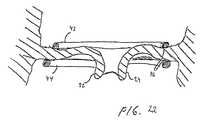
- FIG. 22is a perspective view showing the implanted device after the restraining member has been degraded.
- FIG. 1illustrates a patient 10 having a heart 12 shown in cross-section including a left ventricle 14 and a right ventricle 16 .
- the concepts of the present inventionare suitable to be applied, for example, to a mitral valve 18 which supplies blood into left ventricle 14 .
- Mitral valve 18as better shown in FIG. 1A , includes an annulus 20 and a pair of leaflets 22 , 24 which selectively allow and prevent blood flow into left ventricle 14 .
- valve tissueis used extensively throughout this disclosure in reference to the drawings. The inventive principles are equally applicable when referring to any valve tissue such as annulus tissue, leaflet tissue or other attached vessel tissue.
- Leaflets 22 , 24are supported for coaptation by chordae tendinae or chords 26 , 28 extending upwardly from respective papillary muscles 30 , 32 . Blood enters left ventricle 14 through mitral valve 18 and is expelled during subsequent contraction of heart 12 through aortic valve 34 . It will be appreciated that the present invention is applicable to tricuspidal heart valves as well.
- a device 40 according to a first embodiment of the present inventionis shown in FIGS. 2-4 .
- the devicecomprises a first and a second support member 42 , 44 .
- the first support member 42is continuous with the second support member 44 .
- the first and second support members 42 , 44are formed from a shape memory material, such as alloys based on e.g. Nitinol, copper-zinc-aluminium, or copper-aluminium-nickel, or a shape memory polymer, which may be polynorborene-, polyisoprene-, styrene butadiene-, and polyurethane-based materials and vinyl acetate- and polyester-based compounds.
- the first and second support members 42 , 44have an inactivated shape and an activated shape.
- the support members 42 , 44are flexible and may be easily deformed.
- the support members 42 , 44have a strong strive towards assuming a desired, preprogrammed shape.
- the support members 42 , 44may enter an activated shape by being exposed to a temperature above a transition temperature.
- the device 40may be inserted in a low invasive manner, the support member 42 , 44 being in the inactivated shape.
- the device 40may then assume the desired shape when placed in the proper position in the patient by the support members 42 , 44 being brought to their activated shape.
- the support members 42 , 44may be arranged to be brought into the activated shape by receiving induced heating at selective portions of the support members 42 , 44 .
- selective portions of the support members 42 , 44may be brought to the activated shape and the heating controls what shape the support members 42 , 44 will assume.
- the selective heatingmay be accomplished by a catheter with a heating element, which may be brought in contact with selective parts of the support members 42 , 44 .
- the device 40further comprises a restraining member 45 .
- the restraining member 45is arranged to prevent the support members 42 , 44 from fully assuming the desired activated shape.
- the restraining member 45is coil-shaped and is formed from a biodegradable material, such as a material based on polyglycolic acid, copolymers of glycolic acid and lactic acid, or various lactide polymers.
- the biodegradable materialwill be degraded or resorbed when implanted in a patient.
- the time period for degradationwill depend on the particular material and the thickness of the restraining member 45 . Thus, this may be controlled by the design of the restraining member 45 .
- the first and second support members 42 , 44may be wound around the restraining member 45 .
- the device 40may be arranged in a generally elongate shape in the inactivated shape of the support members 42 , 44 . This elongate shape is suitable for placing the device 40 inside a catheter for insertion into a patient.
- the coil-shaped restraining member 45is thus stretched out for allowing it to be placed inside a catheter.
- the device 40is shown with the support members 42 , 44 being in an activated shape.
- the restraining member 45has assumed its coil-shape and prevents the support members 42 , 44 from fully obtaining the activated shape.
- the restraining member 45forces the support members 42 , 44 to follow a coil-shape having a larger radius of curvature than the preprogrammed shape.
- the restraining member 45When implanted in a patient, the restraining member 45 will be degraded.
- FIG. 4the device 40 is shown after the restraining member 45 has been degraded and the first and second support members have fully assumed the activated, preprogrammed shape.
- the first and second support members 42 , 44now form a general coiled configuration in the form of a spiral or key ring-type configuration with two loops.
- the restraining member 45may be withdrawn during implantation of the device 40 in a patient.
- the restraining member 45may be withdrawn when the first and second support members 42 , 44 have been properly placed allowing the support members 42 , 44 to fully assume the activated shape. This implies that a surgeon may see the result of the full shape change of the support members 42 , 44 during implantation of the device 40 and may directly get an indication of the success of the surgery.
- the restraining membermay be implemented as one or more bars extending between different positions on the first and second support members 42 , 44 . These bars may thus keep the positions on the support members 42 , 44 at a fixed distance to each other and, in this way, prevent the support members 42 , 44 to fully assume the activated shape.
- the barsmay be formed from a biodegradable material as described above. Alternatively, the bars may be detached from the support members 42 , 44 and removed during implantation, or the bars may be cut during implantation in order to remove the restraining action of the bars.
- a device 340comprises a first and a second support member 342 , 344 .
- the first support member 342is continuous with the second support member 344 .
- the first and second support members 342 , 344are formed from a shape memory material.
- the first and second support members 342 , 344are coated with a biodegradable sheath 345 .
- the first and second support members 342 , 344may be immersed in a biodegradable material being in a liquid state.
- the first and second support members 342 , 344may be immersed into the biodegradable material in an inactivated, flexible state, while being held in a coil-shape that may fit for placing the device within a heart such that the first and second support members may conform to the shape of at least a part of the valve annulus at opposite sides of the valve.
- the first and second support members 342 , 344may thus be embedded in a biodegradable sheath 345 .
- the first and second support members 342 , 344are allowed to assume the activated shape, wherein a reduced radius of the coil-shape is obtained as illustrated in FIG. 6 .
- a device 440comprises a first and a second support member 442 , 444 .
- the first support member 442is continuous with the second support member 444 .
- the first and second support members 442 , 444are formed from a shape memory material.
- the first and second support members 442 , 444are tubular.
- the device 440further comprises an elongate restraining member 445 that may be arranged extending within the tubular first and second support members 442 , 444 .
- the restraining member 445may be pushed to extend through the entire first and second support members 442 , 444 in order to force the first and second support members 442 , 444 to a coil-shape with a large radius.
- the second support member 44has an outer boundary which is greater than the outer boundary of the first support member 42 .
- the support members 42 , 44have corresponding shapes with the second support member 44 being in larger scale than the first support member 42 . This is advantageous in creating a pinch of the valve tissue between the first and second support members 42 , 44 , as will be described below with reference to FIG. 14 .
- An end of the second support member 44 and the corresponding end of the restraining member 45which will lead the coil during insertion of the device 40 at the valve, has a greater pitch than the rest of the coil. This implies that the leading end of the coil during rotation into position in the valve will project from immediate contact with the valve tissue and, therefore, the risk that the coil is caught by the chords is diminished.
- the device 40is shown in cross-section in FIG. 9 .
- the first and second support members 42 , 44have a round cross-sectional shape. Opposed surfaces 46 of the first and second support members 42 , 44 provide a pinch to trap valve tissue therebetween.
- the round cross-sectionis also advantageous in creating a pinch of the valve tissue which will not harm the leaflets in their movement during normal heart action, as will be further described below with reference to FIG. 21 .
- FIGS. 10-12A device 140 according to a second embodiment of the present invention is shown in FIGS. 10-12 .
- the device 140comprises a first and a second support member 142 , 144 .
- the first support member 142is continuous with the second support member 144 .
- the first and second support members 142 , 144are formed from a mesh-type or netlike structure, such as stents.
- the first and second support members 142 , 144have an inherent adaptation to a shape change such that an increased cross-section of at least part of the support member 142 , 144 is associated with a shortened length of the support member 142 , 144 . This foreshortening is accomplished in that the mesh-type structure, when expanded in cross-section, pulls the ends of the support members 142 , 144 towards each other.
- the support members 142 , 144present a shape change that may be controlled.
- the shape changewill not occur until a force is applied for increasing the cross-section of at least part of the first and second support members 142 , 144 .
- This implies that the second embodiment as well as the first embodimentprovides a possibility to place a device in relation to a heart valve and, thereafter, control the point of time when the device placed at the heart valve is going to perform a change of shape.
- the device 140is shown with the support members 142 , 144 arranged in a first shape suitable for being attached to the heart valve.
- the support members 142 , 144conform to the shape of the heart valve annulus, such that the support members 142 , 144 may be attached to the annulus along the entire course of the support members 142 , 144 .
- the first and second support members 142 , 144form a general coiled configuration in the form of a spiral or key ring-type configuration with two loops, such that the support members 142 , 144 may abut opposite sides of a heart valve.
- the device 140is shown after the support members 142 , 144 have been exposed to a force increasing the cross-section of the support members 142 , 144 .
- the increased cross-sectionhas forced the support members 142 , 144 to shorten.
- the first and second support members 142 , 144now form a coiled configuration having a decreased radius of curvature to accommodate to the shortened length of the support members 142 , 144 .
- FIGS. 12 a - cdifferent cross-sections of the first and second support members 142 , 144 are illustrated.
- the support members 142 , 144are tubular having a circular cross-section.
- the support members 142 , 144have a U-shaped cross-section. Both these cross-sections are suitable for receiving an inflatable balloon inside the cross-sectional structure. Inflation of the balloon will thus force the cross-section to increase radially.
- the support members 142 , 144are belt-shaped having a linear cross-section. This cross-section may be increased by pulling the edges of the belt apart.
- a device 540 according to a third embodimentis shown in FIGS. 13-15 .
- the device 540comprises a first and a second support member 542 , 544 .
- the first support member 542is continuous with the second support member 544 .
- the first and second support members 542 , 544are formed from a shape memory material.
- the shape memory materialis treated to form a first and a second activated shape.
- the first and second support members 542 , 544may thus assume two different shapes depending on the temperature of the device 540 .
- the device 540is flexible and may be arranged in an elongate form in order to facilitate introduction of the device to a heart of a patient via a catheter.
- the device 540may be cooled during introduction in the catheter in order to maintain its inactivated shape.
- the device 540may then be heated to a first temperature by utilizing the body temperature.
- the device 540is brought to the first activated shape as illustrated in FIG. 14 forming a coil-shape with a large radius suitable for placing the first and second support members 542 , 544 in contact with opposite sides of a heart valve and fixing the position of the support members 542 , 544 to the valve annulus.
- the device 540may further be heated to a second temperature by further utilizing the body temperature.
- the deviceis brought to the second activated shape as illustrated in FIG. 15 .
- the device 540 in the second activated shapeforms a coil-shape with a smaller radius suitable for diminishing a radius of the valve annulus.
- FIGS. 16-17A device 240 according to a fourth embodiment of the present invention is shown in FIGS. 16-17 .
- the device 240comprises only one support member 242 .
- the support member 242is arranged to be placed only on one side of a heart valve.
- the support member 242may be formed from a shape memory material having an inactivated shape and an activated shape. In the inactivated shape, the support member 242 is flexible and may be easily deformed. In the activated shape, the support member 242 has a strong strive towards assuming a desired, preprogrammed shape.
- the device 240may be inserted in a low invasive manner, the support member 242 being in the inactivated shape. The device 240 may then assume the desired shape when placed in the proper position in the patient by the support member 242 being brought to their activated shape.
- the device 240may further comprise a restraining member (not shown), which is arranged to prevent the support member 242 from fully assuming the desired activated shape.
- the restraining membermay thus control the point of time when the support member 242 is fully brought to its desired activated shape.
- the support member 242may be wound around the restraining member or the restraining member may extend between two positions on the support member fixating the distance between these positions.
- the support member 242may alternatively be formed from a mesh-type or netlike structure having an inherent adaptation to a shape change such that an increased cross-section of at least part of the support member 242 is associated with a shortened length of the support member 242 .
- the support member 242presents a shape change that may be controlled. The shape change will not occur until a force is applied for increasing the cross-section of at least part of the support member 242 .
- the support member 240may be formed from a shape memory material treated to form a first and a second activated shape.
- the device 240is shown with the support member 242 being in a first shape conforming to the shape of the annulus of the heart valve to be treated.
- the device 240is shown after the support member 242 has been allowed to perform a change of shape to assume the desired shape. Either a restraining action of a restraining member has been removed or a cross-section of the support member 242 has been increased in order to activate the shape change.
- the support member 242has now changed shape to decrease a radius of curvature for remodelling the heart valve and decreasing the size of the heart valve annulus.
- the concept of this methodmay be applied to the device according to the second, third or fourth embodiments as well, as would be understood by a person skilled in the art.
- the shape change of the devicemay be activated in different ways, depending on the embodiment of the device. However, the point of time when the shape change is activated may be controlled irrespective of which embodiment is used. Thus, it may be ascertained that the device is firmly attached to the heart valve before the shape change occurs, such that the heart valve may be properly remodelled as will be described below.
- FIG. 18 athe device 40 is shown when being inserted to the mitral valve 18 .
- the device 40is being carried in a catheter 50 , which extends from the outside of the patient into the heart.
- the device 40may be pushed out of the catheter 50 using a gripping tool (not shown) extending through the catheter 50 .
- the restraining member 45assumes its coil-shape.
- An end of the restraining member and the second support member 44is brought to the opening of the mitral valve 18 at a commissure between the leaflets 22 , 24 , as shown in FIG. 18 b .
- the endis led through the opening and the device 40 is turned 360 degrees.
- the second support member 44will be rotated into place on one side of the valve 18 , whereas the first support member 42 is placed on the opposite side of the valve 18 .
- the first and second support members 42 , 44are now brought to their activated shape by e.g. heating them above a transition temperature.
- the heatingmay be provided by the body temperature of the patient or by means of heating energy being transmitted through a conductor (not shown) in the catheter. This implies that the first and second support members 42 , 44 strive towards assuming the preprogrammed shape.
- the first and second support members 42 , 44 on opposite sides of the valvewill now be drawn towards each other for securely trapping valve tissue therebetween.
- the restraining member 45will prevent the first and second support members 42 , 44 from fully assuming the activated shape and, thus, from reducing the radius of curvature of the coil-shape. In this way, the device 40 is arranged in engagement with the valve 18 , as shown in FIG. 19 .
- the support members 42 , 44are now placed on opposite sides of the valve 18 pinching valve tissue therebetween to maintain a shape of the valve 18 .
- the support members 42 , 44may have roughened, opposed surfaces 46 to better keep the leaflets 22 , 24 from slipping through the pinch. This implies that the position of the support members 42 , 44 relative the heart valve is initially fixed.
- the device 40may now be secured to the valve 18 for strengthening the fixation of the relative position between the support members 42 , 44 and the valve tissue.
- the support members 42 , 44may comprise respective bores 54 through the opposed support members for receiving separate fasteners 56 .
- the fasteners 56may be threaded or unthreaded pins and may be pushed into position extending through bores in both support members and valve tissue therebetween.
- the fastenermay have an end 58 with larger diameter than the bores 54 such that the fastener 56 may not fall through the bore 54 .
- the device 40is firmly attached to the valve 18 for keeping the valve annulus 20 in its reshaped form, as illustrated in FIG. 20 a .
- Many alternative embodiments of the fastenersmay be contemplated. As shown in FIG.
- the fasteners 56may have an end 60 with an expandable diameter for securing the fastener 56 after it has been pushed through the bores 54 .
- the fastener 56 ′may have a curved portion 60 ′ for gripping around one of the support members, such that the fastener 56 ′ may extend through a bore 54 in one support member and around the other support member, as illustrated in FIG. 20 b .
- the fastenersmay be clips, sutures, or projections that are extendable from at least one of the support members for engaging the valve tissue.
- the second support member 44is slightly displaced radially with respect to the first support member 42 .
- the pinch between the first and second support membersis therefore not sharply defined in a radial direction of the valve.
- the pinching forcedoes not affect the movement of the leaflets during normal heart action and there is a diminished risk of rupture in the leaflets at the pinch.
- the support membersare interrelated in such manner that the outer boundary of the first support member 42 has a diameter corresponding to a line through the center of the second support member 44 .
- the support members 42 , 44overlap somewhat such that tissue is not allowed to move through the pinch and the shape of the valve is maintained. Further, the cross-section of the support members 42 , 44 is round, which also gives a soft contact between the support members and the valve tissue to further diminish the risk of rupture in the leaflets.
- the catheter 50will be retracted and the device 40 is left in the patient.
- the restraining member 45will be degraded in the patient during a time period of a few weeks. During this time, the support members 42 , 44 will grow into the valve tissue for further securing the support members 42 , 44 to the valve.
- the support members 42 , 44are able to fully assume the activated shape.
- the support members 42 , 44will reduce the radius of curvature of the coil-shape and bring the pinched valve tissue in the shape change so as to remodel the valve, as illustrated in FIG. 22 .
- the leaflets 22 , 24are thus brought closer together for ensuring that they may close the valve properly.
- the access to the heart valvemay be achieved endoscopically or with open heart surgery.
- the device 40may have a coil-shape already during insertion into the heart.
- the support membersmay have elliptical, circular or D-shaped forms.
- One or both support membersneed not make an angular turn of 360° such as to have a C or U-shape instead.
- the course of the support membermay be changed such that a radius of curvature is increased locally. Further, the course of the support member may be changed to introduce a depression or recess in the course of the support member.
Landscapes
- Health & Medical Sciences (AREA)
- Cardiology (AREA)
- Oral & Maxillofacial Surgery (AREA)
- Transplantation (AREA)
- Engineering & Computer Science (AREA)
- Biomedical Technology (AREA)
- Heart & Thoracic Surgery (AREA)
- Vascular Medicine (AREA)
- Life Sciences & Earth Sciences (AREA)
- Animal Behavior & Ethology (AREA)
- General Health & Medical Sciences (AREA)
- Public Health (AREA)
- Veterinary Medicine (AREA)
- Prostheses (AREA)
Abstract
Description
Claims (31)
Priority Applications (2)
| Application Number | Priority Date | Filing Date | Title |
|---|---|---|---|
| US12/880,007US9119718B2 (en) | 2005-09-07 | 2010-09-10 | Device and method for improving the function of a heart valve |
| US14/818,163US10195029B2 (en) | 2005-09-07 | 2015-08-04 | Device and method for improving the function of a heart valve |
Applications Claiming Priority (4)
| Application Number | Priority Date | Filing Date | Title |
|---|---|---|---|
| SE0501993 | 2005-09-07 | ||
| SE0501993-0 | 2005-09-07 | ||
| SE0501993 | 2005-09-07 | ||
| PCT/SE2006/001019WO2007030063A1 (en) | 2005-09-07 | 2006-09-05 | A device and method for improving the function of a heart valve |
Related Parent Applications (1)
| Application Number | Title | Priority Date | Filing Date |
|---|---|---|---|
| PCT/SE2006/001019A-371-Of-InternationalWO2007030063A1 (en) | 2005-09-07 | 2006-09-05 | A device and method for improving the function of a heart valve |
Related Child Applications (1)
| Application Number | Title | Priority Date | Filing Date |
|---|---|---|---|
| US12/880,007DivisionUS9119718B2 (en) | 2005-09-07 | 2010-09-10 | Device and method for improving the function of a heart valve |
Publications (2)
| Publication Number | Publication Date |
|---|---|
| US20090299471A1 US20090299471A1 (en) | 2009-12-03 |
| US8128691B2true US8128691B2 (en) | 2012-03-06 |
Family
ID=37836108
Family Applications (5)
| Application Number | Title | Priority Date | Filing Date |
|---|---|---|---|
| US12/065,884Expired - Fee RelatedUS8128691B2 (en) | 2005-09-07 | 2006-09-05 | Device and method for improving the function of a heart valve |
| US12/880,007Active2026-09-29US9119718B2 (en) | 2005-09-07 | 2010-09-10 | Device and method for improving the function of a heart valve |
| US14/818,163Active2026-12-30US10195029B2 (en) | 2005-09-07 | 2015-08-04 | Device and method for improving the function of a heart valve |
| US16/253,153ActiveUS11241314B2 (en) | 2005-09-07 | 2019-01-21 | Device and method for improving the function of a heart valve |
| US17/646,266AbandonedUS20220117733A1 (en) | 2005-09-07 | 2021-12-28 | Device And Method For Improving The Function Of A Heart Valve |
Family Applications After (4)
| Application Number | Title | Priority Date | Filing Date |
|---|---|---|---|
| US12/880,007Active2026-09-29US9119718B2 (en) | 2005-09-07 | 2010-09-10 | Device and method for improving the function of a heart valve |
| US14/818,163Active2026-12-30US10195029B2 (en) | 2005-09-07 | 2015-08-04 | Device and method for improving the function of a heart valve |
| US16/253,153ActiveUS11241314B2 (en) | 2005-09-07 | 2019-01-21 | Device and method for improving the function of a heart valve |
| US17/646,266AbandonedUS20220117733A1 (en) | 2005-09-07 | 2021-12-28 | Device And Method For Improving The Function Of A Heart Valve |
Country Status (10)
| Country | Link |
|---|---|
| US (5) | US8128691B2 (en) |
| EP (3) | EP2754418B1 (en) |
| JP (4) | JP4958907B2 (en) |
| CN (3) | CN101257862B (en) |
| BR (1) | BRPI0617066A2 (en) |
| CA (3) | CA2954317C (en) |
| ES (1) | ES2566635T3 (en) |
| MX (1) | MX2008002552A (en) |
| PL (1) | PL1922030T3 (en) |
| WO (1) | WO2007030063A1 (en) |
Cited By (35)
| Publication number | Priority date | Publication date | Assignee | Title |
|---|---|---|---|---|
| US20120203331A1 (en)* | 2011-02-08 | 2012-08-09 | Biotronik Ag | Implantation device |
| US8845717B2 (en) | 2011-01-28 | 2014-09-30 | Middle Park Medical, Inc. | Coaptation enhancement implant, system, and method |
| US8888843B2 (en) | 2011-01-28 | 2014-11-18 | Middle Peak Medical, Inc. | Device, system, and method for transcatheter treatment of valve regurgitation |
| WO2016040881A1 (en)* | 2014-09-12 | 2016-03-17 | Mitral Valve Technologies Sarl | Mitral repair and replacement devices and methods |
| US9364326B2 (en) | 2011-06-29 | 2016-06-14 | Mitralix Ltd. | Heart valve repair devices and methods |
| US9592121B1 (en) | 2015-11-06 | 2017-03-14 | Middle Peak Medical, Inc. | Device, system, and method for transcatheter treatment of valvular regurgitation |
| US9700412B2 (en) | 2014-06-26 | 2017-07-11 | Mitralix Ltd. | Heart valve repair devices for placement in ventricle and delivery systems for implanting heart valve repair devices |
| US10039637B2 (en) | 2015-02-11 | 2018-08-07 | Edwards Lifesciences Corporation | Heart valve docking devices and implanting methods |
| US10052199B2 (en) | 2014-02-21 | 2018-08-21 | Mitral Valve Technologies Sarl | Devices, systems and methods for delivering a prosthetic mitral valve and anchoring device |
| US10123874B2 (en) | 2017-03-13 | 2018-11-13 | Middle Peak Medical, Inc. | Device, system, and method for transcatheter treatment of valvular regurgitation |
| US10166098B2 (en) | 2013-10-25 | 2019-01-01 | Middle Peak Medical, Inc. | Systems and methods for transcatheter treatment of valve regurgitation |
| US10226330B2 (en) | 2013-08-14 | 2019-03-12 | Mitral Valve Technologies Sarl | Replacement heart valve apparatus and methods |
| US10226339B2 (en) | 2012-01-31 | 2019-03-12 | Mitral Valve Technologies Sarl | Mitral valve docking devices, systems and methods |
| US10251635B2 (en) | 2014-06-24 | 2019-04-09 | Middle Peak Medical, Inc. | Systems and methods for anchoring an implant |
| US10463479B2 (en) | 2016-08-26 | 2019-11-05 | Edwards Lifesciences Corporation | Heart valve docking coils and systems |
| US10478303B2 (en) | 2017-03-13 | 2019-11-19 | Polares Medical Inc. | Device, system, and method for transcatheter treatment of valvular regurgitation |
| US10500048B2 (en) | 2014-06-18 | 2019-12-10 | Polares Medical Inc. | Mitral valve implants for the treatment of valvular regurgitation |
| US10588742B2 (en) | 2013-08-14 | 2020-03-17 | Mitral Valve Technologies Sarl | Coiled anchor for supporting prosthetic heart valve, prosthetic heart valve, and deployment device |
| US10653524B2 (en) | 2017-03-13 | 2020-05-19 | Polares Medical Inc. | Device, system, and method for transcatheter treatment of valvular regurgitation |
| USD890333S1 (en) | 2017-08-21 | 2020-07-14 | Edwards Lifesciences Corporation | Heart valve docking coil |
| US10722359B2 (en) | 2016-08-26 | 2020-07-28 | Edwards Lifesciences Corporation | Heart valve docking devices and systems |
| US11026791B2 (en) | 2018-03-20 | 2021-06-08 | Medtronic Vascular, Inc. | Flexible canopy valve repair systems and methods of use |
| US11285003B2 (en) | 2018-03-20 | 2022-03-29 | Medtronic Vascular, Inc. | Prolapse prevention device and methods of use thereof |
| US11464634B2 (en) | 2020-12-16 | 2022-10-11 | Polares Medical Inc. | Device, system, and method for transcatheter treatment of valvular regurgitation with secondary anchors |
| US11759321B2 (en) | 2021-06-25 | 2023-09-19 | Polares Medical Inc. | Device, system, and method for transcatheter treatment of valvular regurgitation |
| US11793630B2 (en) | 2013-08-12 | 2023-10-24 | Mitral Valve Technologies Sarl | Apparatus and methods for implanting a replacement heart valve |
| US11877925B2 (en) | 2016-12-20 | 2024-01-23 | Edwards Lifesciences Corporation | Systems and mechanisms for deploying a docking device for a replacement heart valve |
| US11890187B2 (en) | 2010-03-05 | 2024-02-06 | Edwards Lifesciences Corporation | Retaining mechanisms for prosthetic valves |
| US12090049B2 (en) | 2008-06-20 | 2024-09-17 | Edwards Lifesciences Corporation | Retaining mechanisms for prosthetic valves |
| US12102526B2 (en) | 2016-07-08 | 2024-10-01 | Edwards Lifesciences Corporation | Docking station for heart valve prosthesis |
| US12186184B2 (en) | 2017-06-30 | 2025-01-07 | Edwards Lifesciences Corporation | Docking stations for transcatheter valves |
| US12239532B2 (en) | 2010-07-19 | 2025-03-04 | Bmeye B.V. | Cardiac valve repair system and methods of use |
| US12295869B2 (en) | 2017-06-30 | 2025-05-13 | Edwards Lifesciences Corporation | Lock and release mechanisms for trans-catheter implantable devices |
| US12329641B2 (en) | 2016-08-26 | 2025-06-17 | Edwards Lifesciences Corporation | Heart valve docking devices and systems |
| US12440329B2 (en) | 2022-05-27 | 2025-10-14 | Edwards Lifesciences Corporation | Heart valve docking coils and systems |
Families Citing this family (86)
| Publication number | Priority date | Publication date | Assignee | Title |
|---|---|---|---|---|
| US6974476B2 (en)* | 2003-05-05 | 2005-12-13 | Rex Medical, L.P. | Percutaneous aortic valve |
| CN102247225B (en) | 2005-02-28 | 2015-07-22 | 梅德坦提亚国际有限公司 | Device for improving the function of heart valve and kit |
| US8128691B2 (en) | 2005-09-07 | 2012-03-06 | Medtentia International Ltd. Oy | Device and method for improving the function of a heart valve |
| SE530568C2 (en)* | 2006-11-13 | 2008-07-08 | Medtentia Ab | Device and method for improving the function of a heart valve |
| EP2072027B1 (en) | 2007-12-21 | 2020-06-17 | Medtentia International Ltd Oy | pre-annuloplasty device and method |
| US8870950B2 (en) | 2009-12-08 | 2014-10-28 | Mitral Tech Ltd. | Rotation-based anchoring of an implant |
| CA2793839C (en)* | 2010-03-23 | 2018-05-22 | Boston Scientific Scimed, Inc. | Annuloplasty device |
| US8579964B2 (en) | 2010-05-05 | 2013-11-12 | Neovasc Inc. | Transcatheter mitral valve prosthesis |
| US11653910B2 (en) | 2010-07-21 | 2023-05-23 | Cardiovalve Ltd. | Helical anchor implantation |
| US9326853B2 (en) | 2010-07-23 | 2016-05-03 | Edwards Lifesciences Corporation | Retaining mechanisms for prosthetic valves |
| CN103987341B (en)* | 2011-01-04 | 2017-02-22 | 克利夫兰临床基金会 | Apparatus and method for treating a regurgitant heart valve |
| US9554897B2 (en) | 2011-04-28 | 2017-01-31 | Neovasc Tiara Inc. | Methods and apparatus for engaging a valve prosthesis with tissue |
| US9308087B2 (en) | 2011-04-28 | 2016-04-12 | Neovasc Tiara Inc. | Sequentially deployed transcatheter mitral valve prosthesis |
| EP2522309A1 (en)* | 2011-05-10 | 2012-11-14 | Biotronik AG | Valve for a heart valve prosthesis |
| KR20140098794A (en)* | 2011-11-23 | 2014-08-08 | 마이크로벤션, 인코포레이티드 | Embolic device with shaped wire |
| US9078747B2 (en) | 2011-12-21 | 2015-07-14 | Edwards Lifesciences Corporation | Anchoring device for replacing or repairing a heart valve |
| EP2620125B1 (en) | 2012-01-24 | 2017-10-11 | Medtentia International Ltd Oy | An arrangement, a loop-shaped support, a prosthetic heart valve and a method of repairing or replacing a native heart valve |
| US9345573B2 (en) | 2012-05-30 | 2016-05-24 | Neovasc Tiara Inc. | Methods and apparatus for loading a prosthesis onto a delivery system |
| US10849755B2 (en) | 2012-09-14 | 2020-12-01 | Boston Scientific Scimed, Inc. | Mitral valve inversion prostheses |
| US10543088B2 (en) | 2012-09-14 | 2020-01-28 | Boston Scientific Scimed, Inc. | Mitral valve inversion prostheses |
| US20150351906A1 (en) | 2013-01-24 | 2015-12-10 | Mitraltech Ltd. | Ventricularly-anchored prosthetic valves |
| FR2998167B1 (en)* | 2013-03-20 | 2015-01-09 | Marco Vola | DEVICE FOR PERFORMING AN ANNULOPLASTY BY THE TRANSAPICAL PATH OF THE MITRAL VALVE |
| US9572665B2 (en) | 2013-04-04 | 2017-02-21 | Neovasc Tiara Inc. | Methods and apparatus for delivering a prosthetic valve to a beating heart |
| EP2805695A1 (en)* | 2013-05-21 | 2014-11-26 | Medtentia International Ltd Oy | Medical system for annuloplasty |
| US9801710B2 (en)* | 2013-07-09 | 2017-10-31 | Edwards Lifesciences Corporation | Collapsible cardiac implant and deployment system and methods |
| US10195028B2 (en) | 2013-09-10 | 2019-02-05 | Edwards Lifesciences Corporation | Magnetic retaining mechanisms for prosthetic valves |
| CN103548635A (en)* | 2013-11-08 | 2014-02-05 | 苏州市相城区渭塘凤凰泾农业发展有限公司 | Pollution-free culturing method for increasing raspberry yield |
| US9622863B2 (en) | 2013-11-22 | 2017-04-18 | Edwards Lifesciences Corporation | Aortic insufficiency repair device and method |
| CN108836414B (en)* | 2014-02-14 | 2021-06-29 | 爱德华兹生命科学公司 | Percutaneous leaflet augmentation |
| US10327766B2 (en)* | 2014-02-18 | 2019-06-25 | Medtentia International Oy | Stapling device |
| CN106470642B (en)* | 2014-07-03 | 2019-01-22 | 梅德坦提亚国际有限公司 | a valvuloplasty system |
| US9180005B1 (en) | 2014-07-17 | 2015-11-10 | Millipede, Inc. | Adjustable endolumenal mitral valve ring |
| EP3174502B1 (en) | 2014-07-30 | 2022-04-06 | Cardiovalve Ltd | Apparatus for implantation of an articulatable prosthetic valve |
| CN110141399B (en) | 2015-02-05 | 2021-07-27 | 卡迪尔维尔福股份有限公司 | Prosthetic valve with axial sliding frame |
| US10231834B2 (en) | 2015-02-09 | 2019-03-19 | Edwards Lifesciences Corporation | Low profile transseptal catheter and implant system for minimally invasive valve procedure |
| US9848983B2 (en) | 2015-02-13 | 2017-12-26 | Millipede, Inc. | Valve replacement using rotational anchors |
| EP3120877A1 (en)* | 2015-07-24 | 2017-01-25 | B. Braun Melsungen AG | Endoluminal device |
| US10335275B2 (en) | 2015-09-29 | 2019-07-02 | Millipede, Inc. | Methods for delivery of heart valve devices using intravascular ultrasound imaging |
| CN111329541B (en) | 2015-11-17 | 2023-09-19 | 波士顿科学国际有限公司 | Implantable devices and delivery systems for reshaping cardiac annulus |
| CA3007660A1 (en) | 2015-12-15 | 2017-06-22 | Neovasc Tiara Inc. | Transseptal delivery system |
| US11833034B2 (en) | 2016-01-13 | 2023-12-05 | Shifamed Holdings, Llc | Prosthetic cardiac valve devices, systems, and methods |
| US10433952B2 (en) | 2016-01-29 | 2019-10-08 | Neovasc Tiara Inc. | Prosthetic valve for avoiding obstruction of outflow |
| US10363130B2 (en) | 2016-02-05 | 2019-07-30 | Edwards Lifesciences Corporation | Devices and systems for docking a heart valve |
| US10531866B2 (en) | 2016-02-16 | 2020-01-14 | Cardiovalve Ltd. | Techniques for providing a replacement valve and transseptal communication |
| JP6800472B2 (en)* | 2016-06-30 | 2020-12-16 | 合同会社ジャパン・メディカル・クリエーティブ | Artificial valve annulus |
| US20190231525A1 (en) | 2016-08-01 | 2019-08-01 | Mitraltech Ltd. | Minimally-invasive delivery systems |
| CA3031187A1 (en) | 2016-08-10 | 2018-02-15 | Cardiovalve Ltd. | Prosthetic valve with concentric frames |
| US10357361B2 (en) | 2016-09-15 | 2019-07-23 | Edwards Lifesciences Corporation | Heart valve pinch devices and delivery systems |
| WO2018083493A1 (en)* | 2016-11-04 | 2018-05-11 | Cambridge Enterprise Limited | Annuloplasty prosthesis and related methods |
| CA3042588A1 (en) | 2016-11-21 | 2018-05-24 | Neovasc Tiara Inc. | Methods and systems for rapid retraction of a transcatheter heart valve delivery system |
| PT3554424T (en) | 2016-12-16 | 2023-04-03 | Edwards Lifesciences Corp | Deployment systems, tools, and methods for delivering an anchoring device for a prosthetic valve |
| US10813749B2 (en) | 2016-12-20 | 2020-10-27 | Edwards Lifesciences Corporation | Docking device made with 3D woven fabric |
| US11654023B2 (en) | 2017-01-23 | 2023-05-23 | Edwards Lifesciences Corporation | Covered prosthetic heart valve |
| US11185406B2 (en) | 2017-01-23 | 2021-11-30 | Edwards Lifesciences Corporation | Covered prosthetic heart valve |
| US11013600B2 (en) | 2017-01-23 | 2021-05-25 | Edwards Lifesciences Corporation | Covered prosthetic heart valve |
| USD867595S1 (en) | 2017-02-01 | 2019-11-19 | Edwards Lifesciences Corporation | Stent |
| US10548731B2 (en) | 2017-02-10 | 2020-02-04 | Boston Scientific Scimed, Inc. | Implantable device and delivery system for reshaping a heart valve annulus |
| EP3395296B1 (en)* | 2017-04-28 | 2019-12-18 | Medtentia International Ltd Oy | Annuloplasty implant |
| US10842619B2 (en) | 2017-05-12 | 2020-11-24 | Edwards Lifesciences Corporation | Prosthetic heart valve docking assembly |
| US12064347B2 (en) | 2017-08-03 | 2024-08-20 | Cardiovalve Ltd. | Prosthetic heart valve |
| US11793633B2 (en) | 2017-08-03 | 2023-10-24 | Cardiovalve Ltd. | Prosthetic heart valve |
| CA3073834A1 (en) | 2017-08-25 | 2019-02-28 | Neovasc Tiara Inc. | Sequentially deployed transcatheter mitral valve prosthesis |
| JP7609637B2 (en)* | 2018-01-08 | 2025-01-07 | エイチブイアール カーディオ オーイー | Annulus repair device |
| WO2019223975A1 (en)* | 2018-05-21 | 2019-11-28 | Medtentia International Ltd Oy | Annuloplasty device |
| EP3572042A1 (en)* | 2018-05-21 | 2019-11-27 | Medtentia International Ltd Oy | Annuloplasty device |
| US11234818B2 (en) | 2018-05-21 | 2022-02-01 | Medtentia International Ltd Oy | Annuloplasty device |
| AU2019325548B2 (en)* | 2018-08-21 | 2025-06-26 | Shifamed Holdings, Llc | Prosthetic cardiac valve devices, systems, and methods |
| EP3628274B1 (en)* | 2018-09-25 | 2022-03-09 | TruLeaf Medical Ltd. | Mitral annulus repair device |
| CN113260337A (en) | 2018-10-05 | 2021-08-13 | 施菲姆德控股有限责任公司 | Prosthetic heart valve devices, systems, and methods |
| CN113056302B (en) | 2018-10-19 | 2023-03-28 | 施菲姆德控股有限责任公司 | Adjustable medical device |
| CN113271890B (en) | 2018-11-08 | 2024-08-30 | 内奥瓦斯克迪亚拉公司 | Ventricular deployment of transcatheter mitral valve prosthesis |
| EP3897370B1 (en)* | 2018-12-21 | 2025-06-11 | W. L. Gore & Associates, Inc. | Medical treatment system using measurement data from multiple sensors |
| CA3132873A1 (en) | 2019-03-08 | 2020-09-17 | Neovasc Tiara Inc. | Retrievable prosthesis delivery system |
| EP3941391B1 (en) | 2019-03-19 | 2024-12-04 | Shifamed Holdings, LLC | Prosthetic cardiac valve devices, systems |
| CA3135753C (en) | 2019-04-01 | 2023-10-24 | Neovasc Tiara Inc. | Controllably deployable prosthetic valve |
| US11491006B2 (en) | 2019-04-10 | 2022-11-08 | Neovasc Tiara Inc. | Prosthetic valve with natural blood flow |
| US11779742B2 (en) | 2019-05-20 | 2023-10-10 | Neovasc Tiara Inc. | Introducer with hemostasis mechanism |
| JP7520897B2 (en) | 2019-06-20 | 2024-07-23 | ニオバスク ティアラ インコーポレイテッド | Thin prosthetic mitral valve |
| WO2021005246A1 (en)* | 2019-07-11 | 2021-01-14 | Medtentia International Ltd Oy | Annuloplasty device |
| EP3827785A1 (en)* | 2019-11-29 | 2021-06-02 | Medtentia International Ltd Oy | Annuloplasty device |
| EP4114313B1 (en)* | 2020-03-03 | 2025-10-01 | Shifamed Holdings, LLC | Prosthetic cardiac valve devices, systems |
| CN116456937A (en) | 2020-08-31 | 2023-07-18 | 施菲姆德控股有限责任公司 | Prosthetic Valve Delivery System |
| US20230363907A1 (en)* | 2020-09-22 | 2023-11-16 | Shifamed Holdings, Llc | Prosthetic cardiac valve sensor devices, systems, and methods with imaging |
| US12357459B2 (en) | 2020-12-03 | 2025-07-15 | Cardiovalve Ltd. | Transluminal delivery system |
| US12329635B2 (en) | 2020-12-04 | 2025-06-17 | Shifamed Holdings, Llc | Flared prosthetic cardiac valve delivery devices and systems |
| US12201521B2 (en) | 2021-03-22 | 2025-01-21 | Shifamed Holdings, Llc | Anchor position verification for prosthetic cardiac valve devices |
Citations (36)
| Publication number | Priority date | Publication date | Assignee | Title |
|---|---|---|---|---|
| US4042979A (en) | 1976-07-12 | 1977-08-23 | Angell William W | Valvuloplasty ring and prosthetic method |
| US5290300A (en)* | 1989-07-31 | 1994-03-01 | Baxter International Inc. | Flexible suture guide and holder |
| US5403305A (en) | 1993-04-08 | 1995-04-04 | Carbomedics, Inc. | Mitral valve prosthesis rotator |
| WO1999004730A1 (en) | 1997-07-22 | 1999-02-04 | Baxter International Inc. | Expandable annuloplasty ring |
| US6217610B1 (en) | 1994-07-29 | 2001-04-17 | Edwards Lifesciences Corporation | Expandable annuloplasty ring |
| US6258117B1 (en) | 1999-04-15 | 2001-07-10 | Mayo Foundation For Medical Education And Research | Multi-section stent |
| US20020013621A1 (en) | 2000-07-27 | 2002-01-31 | Robert Stobie | Heart valve holder for constricting the valve commissures and methods of use |
| US6368348B1 (en) | 2000-05-15 | 2002-04-09 | Shlomo Gabbay | Annuloplasty prosthesis for supporting an annulus of a heart valve |
| US6406492B1 (en) | 1999-04-08 | 2002-06-18 | Sulzer Carbomedics Inc. | Annuloplasty ring holder |
| US6406493B1 (en)* | 2000-06-02 | 2002-06-18 | Hosheng Tu | Expandable annuloplasty ring and methods of use |
| US6419696B1 (en)* | 2000-07-06 | 2002-07-16 | Paul A. Spence | Annuloplasty devices and related heart valve repair methods |
| US20020143381A1 (en)* | 2001-03-27 | 2002-10-03 | Scimed Life Systems, Inc. | Stent with controlled expansion |
| US20030045929A1 (en) | 2001-08-28 | 2003-03-06 | Mccarthy Patrick M. | Tricuspid ring and template |
| US20030069593A1 (en) | 2001-08-31 | 2003-04-10 | Tremulis William S. | Method and apparatus for valve repair |
| US6585767B1 (en) | 1998-11-23 | 2003-07-01 | Agion Technologies, Inc. | Antimicrobial suturing ring for heart valve |
| US6602289B1 (en) | 1999-06-08 | 2003-08-05 | S&A Rings, Llc | Annuloplasty rings of particular use in surgery for the mitral valve |
| US20030199975A1 (en) | 2000-05-22 | 2003-10-23 | Shlomo Gabbay | Low invasive implantable cardiac prosthesis and method for helping improve operation of a heart valve |
| WO2003105730A1 (en) | 2000-06-02 | 2003-12-24 | 3F Therapeutics, Inc. | Expandable medical implant and percutaneous delivery |
| US20040019357A1 (en) | 2002-07-26 | 2004-01-29 | Campbell Louis A. | Annuloplasty ring holder |
| US6723038B1 (en) | 2000-10-06 | 2004-04-20 | Myocor, Inc. | Methods and devices for improving mitral valve function |
| US20040106989A1 (en) | 2002-07-03 | 2004-06-03 | Wilson Robert F. | Leaflet reinforcement for regurgitant valves |
| US20040127981A1 (en) | 2000-09-20 | 2004-07-01 | Ample Medical, Inc. | Devices, systems, and methods for retaining a native heart valve leaflet |
| US20040138745A1 (en) | 2001-10-01 | 2004-07-15 | Ample Medical, Inc. | Methods and devices for heart valve treatments |
| US20040148021A1 (en) | 2002-08-29 | 2004-07-29 | Cartledge Richard G. | Implantable devices for controlling the internal circumference of an anatomic orifice or lumen |
| US20040162611A1 (en) | 2001-08-24 | 2004-08-19 | Salvador Marquez | Method of implanting a self-molding annuloplasty ring |
| WO2004089250A1 (en) | 2003-03-30 | 2004-10-21 | Fidel Realyvasquez | Apparatus and methods for valve repair |
| US20040220593A1 (en) | 2003-05-01 | 2004-11-04 | Secant Medical, Llc | Restraining clip for mitral valve repair |
| US20040243230A1 (en) | 2003-05-20 | 2004-12-02 | The Cleveland Clinic Foundation | Apparatus and methods for repair of a cardiac valve |
| US20040260393A1 (en) | 2000-09-20 | 2004-12-23 | Ample Medical, Inc. | Devices, systems, and methods for reshaping a heart valve annulus |
| WO2005039452A1 (en) | 2003-10-23 | 2005-05-06 | Roberto Erminio Parravicini | A prosthetic valve apparatus, in particular for cardiac applications |
| US20050149178A1 (en) | 2000-07-06 | 2005-07-07 | Medtentia Ab | Annuloplasty instrument |
| US20050288777A1 (en) | 2004-06-29 | 2005-12-29 | Rhee Richard S | Thermal conductor for adjustable cardiac valve implant |
| WO2006065212A1 (en) | 2004-12-15 | 2006-06-22 | Medtentia Ab | A device and method for improving the function of a heart valve |
| WO2006091163A1 (en) | 2005-02-28 | 2006-08-31 | Medtentia Ab | Devices and a kit for improving the function of a heart valve |
| WO2006093656A1 (en) | 2005-02-28 | 2006-09-08 | Medtronic Vascular, Inc. | Device, system, and method for aiding valve annuloplasty |
| WO2007030063A1 (en) | 2005-09-07 | 2007-03-15 | Medtentia Ab | A device and method for improving the function of a heart valve |
Family Cites Families (71)
| Publication number | Priority date | Publication date | Assignee | Title |
|---|---|---|---|---|
| NL143127B (en) | 1969-02-04 | 1974-09-16 | Rhone Poulenc Sa | REINFORCEMENT DEVICE FOR A DEFECTIVE HEART VALVE. |
| DE1960542B2 (en) | 1969-12-03 | 1973-03-22 | Matthias & Rene Dick, 5050 Porz | SOUND-INSULATING PIPE FASTENING |
| FR2306671A1 (en) | 1975-04-11 | 1976-11-05 | Rhone Poulenc Ind | VALVULAR IMPLANT |
| US3997923A (en) | 1975-04-28 | 1976-12-21 | St. Jude Medical, Inc. | Heart valve prosthesis and suturing assembly and method of implanting a heart valve prosthesis in a heart |
| US4489446A (en)* | 1982-07-14 | 1984-12-25 | Reed Charles C | Heart valve prosthesis |
| DE3230858C2 (en) | 1982-08-19 | 1985-01-24 | Ahmadi, Ali, Dr. med., 7809 Denzlingen | Ring prosthesis |
| US4535483A (en) | 1983-01-17 | 1985-08-20 | Hemex, Inc. | Suture rings for heart valves |
| US4863460A (en) | 1986-03-04 | 1989-09-05 | Sta-Set Corporation | Suture rings for heart valves |
| JPS6337894A (en) | 1986-07-30 | 1988-02-18 | Mitsubishi Electric Corp | random access memory |
| CA1303298C (en) | 1986-08-06 | 1992-06-16 | Alain Carpentier | Flexible cardiac valvular support prosthesis |
| US4917698A (en) | 1988-12-22 | 1990-04-17 | Baxter International Inc. | Multi-segmented annuloplasty ring prosthesis |
| DE69010890T2 (en) | 1989-02-13 | 1995-03-16 | Baxter Int | PARTLY FLEXIBLE RING-SHAPED PROSTHESIS FOR IMPLANTING AROUND THE HEART-VALVE RING. |
| NZ228382A (en) | 1989-03-17 | 1992-08-26 | Carter Holt Harvey Plastic Pro | Drug administering coil-like device for insertion in body cavity of animal |
| DE69331315T2 (en) | 1992-01-27 | 2002-08-22 | Medtronic, Inc. | ANULOPLASTIC AND SEAM RINGS |
| US5306296A (en) | 1992-08-21 | 1994-04-26 | Medtronic, Inc. | Annuloplasty and suture rings |
| US5201880A (en) | 1992-01-27 | 1993-04-13 | Pioneering Technologies, Inc. | Mitral and tricuspid annuloplasty rings |
| US5163953A (en) | 1992-02-10 | 1992-11-17 | Vince Dennis J | Toroidal artificial heart valve stent |
| FR2708458B1 (en) | 1993-08-03 | 1995-09-15 | Seguin Jacques | Prosthetic ring for cardiac surgery. |
| AU1301095A (en) | 1993-12-13 | 1995-07-03 | Brigham And Women's Hospital | Aortic valve supporting device |
| US5593435A (en) | 1994-07-29 | 1997-01-14 | Baxter International Inc. | Distensible annuloplasty ring for surgical remodelling of an atrioventricular valve and nonsurgical method for post-implantation distension thereof to accommodate patient growth |
| DE69630235T2 (en) | 1995-12-01 | 2004-08-05 | Medtronic, Inc., Minneapolis | Annuloplasty prosthesis |
| US6207610B1 (en) | 1996-05-17 | 2001-03-27 | Degussa-Huls Ag | Compacts based on pyrogenically produced silicon dioxide |
| US5669919A (en) | 1996-08-16 | 1997-09-23 | Medtronic, Inc. | Annuloplasty system |
| US5716397A (en) | 1996-12-06 | 1998-02-10 | Medtronic, Inc. | Annuloplasty device with removable stiffening element |
| US5908450A (en) | 1997-02-28 | 1999-06-01 | Medtronic, Inc. | Physiologic mitral valve implantation holding system |
| US5776189A (en) | 1997-03-05 | 1998-07-07 | Khalid; Naqeeb | Cardiac valvular support prosthesis |
| US20020095175A1 (en)* | 1998-02-24 | 2002-07-18 | Brock David L. | Flexible instrument |
| US6059827A (en) | 1998-05-04 | 2000-05-09 | Axya Medical, Inc. | Sutureless cardiac valve prosthesis, and devices and methods for implanting them |
| US10327743B2 (en)* | 1999-04-09 | 2019-06-25 | Evalve, Inc. | Device and methods for endoscopic annuloplasty |
| US6183512B1 (en) | 1999-04-16 | 2001-02-06 | Edwards Lifesciences Corporation | Flexible annuloplasty system |
| US6348068B1 (en) | 1999-07-23 | 2002-02-19 | Sulzer Carbomedics Inc. | Multi-filament valve stent for a cardisc valvular prosthesis |
| US6458153B1 (en) | 1999-12-31 | 2002-10-01 | Abps Venture One, Ltd. | Endoluminal cardiac and venous valve prostheses and methods of manufacture and delivery thereof |
| CN1806775A (en) | 2000-01-14 | 2006-07-26 | 维亚科公司 | Tissue annuloplasty band and apparatus and method for fashioning, sizing and implanting the same |
| US6402781B1 (en) | 2000-01-31 | 2002-06-11 | Mitralife | Percutaneous mitral annuloplasty and cardiac reinforcement |
| GB0004527D0 (en) | 2000-02-26 | 2000-04-19 | Avecia Ltd | Inks |
| EP1330189B1 (en)* | 2000-06-23 | 2007-12-19 | Viacor Incorporated | Automated annular plication for mitral valve repair |
| US7381220B2 (en) | 2000-09-20 | 2008-06-03 | Ample Medical, Inc. | Devices, systems, and methods for supplementing, repairing, or replacing a native heart valve leaflet |
| US6716244B2 (en) | 2000-12-20 | 2004-04-06 | Carbomedics, Inc. | Sewing cuff assembly for heart valves |
| CN2464273Y (en)* | 2001-01-18 | 2001-12-12 | 康云帆 | Cardiac partition defect reparing support |
| US7367991B2 (en) | 2001-08-28 | 2008-05-06 | Edwards Lifesciences Corporation | Conformal tricuspid annuloplasty ring and template |
| US20030065386A1 (en)* | 2001-09-28 | 2003-04-03 | Weadock Kevin Shaun | Radially expandable endoprosthesis device with two-stage deployment |
| US6719786B2 (en) | 2002-03-18 | 2004-04-13 | Medtronic, Inc. | Flexible annuloplasty prosthesis and holder |
| US7101395B2 (en)* | 2002-06-12 | 2006-09-05 | Mitral Interventions, Inc. | Method and apparatus for tissue connection |
| CN100553590C (en)* | 2002-10-01 | 2009-10-28 | 安普尔医药公司 | The device of finishing semilunar valve annulus |
| JP4960631B2 (en) | 2002-10-11 | 2012-06-27 | ユニバーシティ オブ コネチカット | Shape memory polymers based on semi-crystalline thermoplastic polyurethane with nanostructured hard segments |
| US20050119735A1 (en) | 2002-10-21 | 2005-06-02 | Spence Paul A. | Tissue fastening systems and methods utilizing magnetic guidance |
| US6997950B2 (en) | 2003-01-16 | 2006-02-14 | Chawla Surendra K | Valve repair device |
| ITRM20030060A1 (en) | 2003-02-12 | 2004-08-13 | Carlo Fucci | PROSTHETIC RING FOR MITRAL VALVE. |
| US20050107871A1 (en) | 2003-03-30 | 2005-05-19 | Fidel Realyvasquez | Apparatus and methods for valve repair |
| US7186265B2 (en) | 2003-12-10 | 2007-03-06 | Medtronic, Inc. | Prosthetic cardiac valves and systems and methods for implanting thereof |
| US20050177228A1 (en)* | 2003-12-16 | 2005-08-11 | Solem Jan O. | Device for changing the shape of the mitral annulus |
| US8603160B2 (en) | 2003-12-23 | 2013-12-10 | Sadra Medical, Inc. | Method of using a retrievable heart valve anchor with a sheath |
| PT1561437E (en)* | 2004-02-06 | 2010-03-05 | Sangomed S R L | External support for restoring competence to venous valves by traction of their intercommissural walls |
| US7311730B2 (en)* | 2004-02-13 | 2007-12-25 | Shlomo Gabbay | Support apparatus and heart valve prosthesis for sutureless implantation |
| US7942927B2 (en)* | 2004-03-15 | 2011-05-17 | Baker Medical Research Institute | Treating valve failure |
| WO2005112832A1 (en) | 2004-05-14 | 2005-12-01 | St. Jude Medical, Inc. | Systems and methods for holding annuloplasty rings |
| US20080015688A1 (en)* | 2004-06-29 | 2008-01-17 | Micardia Corporation | Adjustable multi-segment cardiac valve implant with selective dimensional adjustment |
| US7285087B2 (en)* | 2004-07-15 | 2007-10-23 | Micardia Corporation | Shape memory devices and methods for reshaping heart anatomy |
| US8083793B2 (en) | 2005-02-28 | 2011-12-27 | Medtronic, Inc. | Two piece heart valves including multiple lobe valves and methods for implanting them |
| US20060195186A1 (en) | 2005-02-28 | 2006-08-31 | Drews Michael J | Connectors for two piece heart valves and methods for implanting such heart valves |
| US8267993B2 (en) | 2005-06-09 | 2012-09-18 | Coroneo, Inc. | Expandable annuloplasty ring and associated ring holder |
| US20070138745A1 (en)* | 2005-12-19 | 2007-06-21 | Duncan Eugenia A | Educational card game and related methods of use therefor |
| US8214516B2 (en)* | 2006-01-06 | 2012-07-03 | Google Inc. | Dynamic media serving infrastructure |
| US7967857B2 (en) | 2006-01-27 | 2011-06-28 | Medtronic, Inc. | Gasket with spring collar for prosthetic heart valves and methods for making and using them |
| WO2007138571A2 (en) | 2006-06-01 | 2007-12-06 | Mor Research Applications Ltd. | Membrane augmentation, such as of for treatment of cardiac valves, and fastening devices for membrane augmentation |
| SE530568C2 (en) | 2006-11-13 | 2008-07-08 | Medtentia Ab | Device and method for improving the function of a heart valve |
| US8337390B2 (en) | 2008-07-30 | 2012-12-25 | Cube S.R.L. | Intracardiac device for restoring the functional elasticity of the cardiac structures, holding tool for the intracardiac device, and method for implantation of the intracardiac device in the heart |
| US8287591B2 (en) | 2008-09-19 | 2012-10-16 | Edwards Lifesciences Corporation | Transformable annuloplasty ring configured to receive a percutaneous prosthetic heart valve implantation |
| CR20190069A (en)* | 2016-08-26 | 2019-05-14 | Edwards Lifesciences Corp | VALVES AND COUPLING SYSTEMS OF CORAZON VALVES |
| EP3476366B1 (en)* | 2017-10-27 | 2020-12-16 | Medtentia International Ltd Oy | Annuloplasty implant |
| WO2021005246A1 (en)* | 2019-07-11 | 2021-01-14 | Medtentia International Ltd Oy | Annuloplasty device |
- 2006
- 2006-09-05USUS12/065,884patent/US8128691B2/ennot_activeExpired - Fee Related
- 2006-09-05EPEP14164114.2Apatent/EP2754418B1/ennot_activeNot-in-force
- 2006-09-05PLPL06784150.2Tpatent/PL1922030T3/enunknown
- 2006-09-05ESES06784150.2Tpatent/ES2566635T3/enactiveActive
- 2006-09-05CNCN2006800327214Apatent/CN101257862B/ennot_activeExpired - Fee Related
- 2006-09-05JPJP2008529955Apatent/JP4958907B2/ennot_activeExpired - Fee Related
- 2006-09-05CACA2954317Apatent/CA2954317C/ennot_activeExpired - Fee Related
- 2006-09-05CACA2872116Apatent/CA2872116C/ennot_activeExpired - Fee Related
- 2006-09-05EPEP06784150.2Apatent/EP1922030B1/ennot_activeNot-in-force
- 2006-09-05CNCN2010106215259Apatent/CN102113922B/ennot_activeExpired - Fee Related
- 2006-09-05CACA2619022Apatent/CA2619022C/ennot_activeExpired - Fee Related
- 2006-09-05EPEP14164113.4Apatent/EP2754417B1/ennot_activeNot-in-force
- 2006-09-05MXMX2008002552Apatent/MX2008002552A/enactiveIP Right Grant
- 2006-09-05CNCN201010621532.9Apatent/CN102113923B/ennot_activeExpired - Fee Related
- 2006-09-05WOPCT/SE2006/001019patent/WO2007030063A1/enactiveApplication Filing
- 2006-09-05BRBRPI0617066-8Apatent/BRPI0617066A2/ennot_activeIP Right Cessation
- 2010
- 2010-09-10USUS12/880,007patent/US9119718B2/enactiveActive
- 2012
- 2012-01-18JPJP2012007595Apatent/JP5528485B2/ennot_activeExpired - Fee Related
- 2013
- 2013-11-11JPJP2013232900Apatent/JP5801371B2/enactiveActive
- 2013-11-11JPJP2013232901Apatent/JP5826813B2/ennot_activeExpired - Fee Related
- 2015
- 2015-08-04USUS14/818,163patent/US10195029B2/enactiveActive
- 2019
- 2019-01-21USUS16/253,153patent/US11241314B2/enactiveActive
- 2021
- 2021-12-28USUS17/646,266patent/US20220117733A1/ennot_activeAbandoned
Patent Citations (42)
| Publication number | Priority date | Publication date | Assignee | Title |
|---|---|---|---|---|
| US4042979A (en) | 1976-07-12 | 1977-08-23 | Angell William W | Valvuloplasty ring and prosthetic method |
| US5290300A (en)* | 1989-07-31 | 1994-03-01 | Baxter International Inc. | Flexible suture guide and holder |
| US5403305A (en) | 1993-04-08 | 1995-04-04 | Carbomedics, Inc. | Mitral valve prosthesis rotator |
| US6217610B1 (en) | 1994-07-29 | 2001-04-17 | Edwards Lifesciences Corporation | Expandable annuloplasty ring |
| US20010021874A1 (en) | 1994-07-29 | 2001-09-13 | Alexandre Carpentier | Expandable annuloplasty ring |
| WO1999004730A1 (en) | 1997-07-22 | 1999-02-04 | Baxter International Inc. | Expandable annuloplasty ring |
| US6585767B1 (en) | 1998-11-23 | 2003-07-01 | Agion Technologies, Inc. | Antimicrobial suturing ring for heart valve |
| US6406492B1 (en) | 1999-04-08 | 2002-06-18 | Sulzer Carbomedics Inc. | Annuloplasty ring holder |
| US6258117B1 (en) | 1999-04-15 | 2001-07-10 | Mayo Foundation For Medical Education And Research | Multi-section stent |
| US6602289B1 (en) | 1999-06-08 | 2003-08-05 | S&A Rings, Llc | Annuloplasty rings of particular use in surgery for the mitral valve |
| US6368348B1 (en) | 2000-05-15 | 2002-04-09 | Shlomo Gabbay | Annuloplasty prosthesis for supporting an annulus of a heart valve |
| US20030199975A1 (en) | 2000-05-22 | 2003-10-23 | Shlomo Gabbay | Low invasive implantable cardiac prosthesis and method for helping improve operation of a heart valve |
| US6406493B1 (en)* | 2000-06-02 | 2002-06-18 | Hosheng Tu | Expandable annuloplasty ring and methods of use |
| WO2003105730A1 (en) | 2000-06-02 | 2003-12-24 | 3F Therapeutics, Inc. | Expandable medical implant and percutaneous delivery |
| US20020173841A1 (en) | 2000-07-06 | 2002-11-21 | Paul A. Spence | Annuloplasty devices and related heart valve repair methods |
| US20040167620A1 (en) | 2000-07-06 | 2004-08-26 | Medtentia | Annuloplasty devices and related heart valve repair methods |
| US7077861B2 (en) | 2000-07-06 | 2006-07-18 | Medtentia Ab | Annuloplasty instrument |
| US20050149178A1 (en) | 2000-07-06 | 2005-07-07 | Medtentia Ab | Annuloplasty instrument |
| US6419696B1 (en)* | 2000-07-06 | 2002-07-16 | Paul A. Spence | Annuloplasty devices and related heart valve repair methods |
| US20020013621A1 (en) | 2000-07-27 | 2002-01-31 | Robert Stobie | Heart valve holder for constricting the valve commissures and methods of use |
| US20040127981A1 (en) | 2000-09-20 | 2004-07-01 | Ample Medical, Inc. | Devices, systems, and methods for retaining a native heart valve leaflet |
| US20040260393A1 (en) | 2000-09-20 | 2004-12-23 | Ample Medical, Inc. | Devices, systems, and methods for reshaping a heart valve annulus |
| US6723038B1 (en) | 2000-10-06 | 2004-04-20 | Myocor, Inc. | Methods and devices for improving mitral valve function |
| US20020143381A1 (en)* | 2001-03-27 | 2002-10-03 | Scimed Life Systems, Inc. | Stent with controlled expansion |
| US20040162611A1 (en) | 2001-08-24 | 2004-08-19 | Salvador Marquez | Method of implanting a self-molding annuloplasty ring |
| US20030045929A1 (en) | 2001-08-28 | 2003-03-06 | Mccarthy Patrick M. | Tricuspid ring and template |
| US20030069593A1 (en) | 2001-08-31 | 2003-04-10 | Tremulis William S. | Method and apparatus for valve repair |
| US20040138745A1 (en) | 2001-10-01 | 2004-07-15 | Ample Medical, Inc. | Methods and devices for heart valve treatments |
| US20040106989A1 (en) | 2002-07-03 | 2004-06-03 | Wilson Robert F. | Leaflet reinforcement for regurgitant valves |
| US20040019357A1 (en) | 2002-07-26 | 2004-01-29 | Campbell Louis A. | Annuloplasty ring holder |
| US20050149114A1 (en) | 2002-08-29 | 2005-07-07 | Cartledge Richard G. | Apparatus for implanting surgical devices for controlling the internal circumference of an anatomic orifice or lumen |
| US20040148021A1 (en) | 2002-08-29 | 2004-07-29 | Cartledge Richard G. | Implantable devices for controlling the internal circumference of an anatomic orifice or lumen |
| WO2004089250A1 (en) | 2003-03-30 | 2004-10-21 | Fidel Realyvasquez | Apparatus and methods for valve repair |
| US20040220593A1 (en) | 2003-05-01 | 2004-11-04 | Secant Medical, Llc | Restraining clip for mitral valve repair |
| US20040243230A1 (en) | 2003-05-20 | 2004-12-02 | The Cleveland Clinic Foundation | Apparatus and methods for repair of a cardiac valve |
| WO2005039452A1 (en) | 2003-10-23 | 2005-05-06 | Roberto Erminio Parravicini | A prosthetic valve apparatus, in particular for cardiac applications |
| US20050288777A1 (en) | 2004-06-29 | 2005-12-29 | Rhee Richard S | Thermal conductor for adjustable cardiac valve implant |
| WO2006054930A1 (en) | 2004-11-19 | 2006-05-26 | Medtentia Ab | Annuloplasty instrument |
| WO2006065212A1 (en) | 2004-12-15 | 2006-06-22 | Medtentia Ab | A device and method for improving the function of a heart valve |
| WO2006091163A1 (en) | 2005-02-28 | 2006-08-31 | Medtentia Ab | Devices and a kit for improving the function of a heart valve |
| WO2006093656A1 (en) | 2005-02-28 | 2006-09-08 | Medtronic Vascular, Inc. | Device, system, and method for aiding valve annuloplasty |
| WO2007030063A1 (en) | 2005-09-07 | 2007-03-15 | Medtentia Ab | A device and method for improving the function of a heart valve |
Non-Patent Citations (24)
| Title |
|---|
| United States Patent and Trademark Office, Final Office Action in U.S. Appl. No. 11/793,028, mailed Feb. 16, 2010, 10 pages. |
| United States Patent and Trademark Office, Final Office Action mailed Aug. 20, 2010 in U.S. Appl. No. 11/885,116, 8 pages. |
| United States Patent and Trademark Office, Non-Final Office Action in U.S. Appl. No. 11/793,028, mailed Jun. 8, 2009, 12 pages. |
| United States Patent and Trademark Office, Non-Final Office Action in U.S. Appl. No. 12/065,884, mailed Sep. 16, 2010, 12 pages. |
| United States Patent and Trademark Office, Notice of Allowance mailed Jan. 24, 2011 in U.S. Appl. No. 11/667,335, 8 pages. |
| United States Patent and Trademark Office, Office Action mailed Mar. 5, 2010 in U.S. Appl. No. 11/885,116, 6 pages. |
| United States Patent and Trademark Office, Office Action mailed May 26, 2009 in U.S. Appl. No. 11/885,116, 13 pages. |
| United States Patent and Trademark Office, Office Action mailed May 7, 2010 in U.S. Appl. No. 11/667,335, 18 pages. |
| WIPO, First Notice Informing the Application of the Communication of the International Application (to Designated Offices Which Do Not Apply the 30 Month Time Limit Under Article 22(I)) (Form PCT/IB/308) dated Sep. 28, 2006 in International Application No. PCT/SE2006/000251, 1 page. |
| WIPO, International Preliminary Report on Patentability dated Jun. 19, 2007 in International Application No. PCT/SE2005/001914, 7 pages. |
| WIPO, International Preliminary Report on Patentability dated Sep. 11, 2007 in International Application No. PCT/SE2006/000251, 1 page. |
| WIPO, International Preliminary Report on Patentability in International Application No. PCT/EP2008/068126 mailed Apr. 22, 2010, 13 pages. |
| WIPO, International Preliminary Report on Patentability in International Application No. PCT/SE2006/001019 mailed Mar. 11, 2008, 12 pages. |
| WIPO, International Search Report dated Apr. 4, 2006 in International Application No. PCT/SE2005/001914, 1 page. |
| WIPO, International Search Report dated Jun. 2, 2006 in International Application No. PCT/SE2006/000251, 5 pages. |
| WIPO, International Search Report in International Application No. PCT/SE2006/001019 mailed Jan. 26, 2007, 8 pages. |
| WIPO, International Search Report mailed Mar. 1, 2006 in International Application No. PCT/SE2005/000909, 6 pages. |
| WIPO, International-Type Search Report dated Sep. 7, 2005 in Swedish Application No. SE2005-0000440-3, 4 pages. |
| WIPO, Notification of the Recording of a Change (Form PCT/IB/306) dated Jan. 11, 2007 in International Application No. PCT/SE2006/000251, 1 page. |
| WIPO, PCT Request Form in dated Feb. 24, 2006 International Application No. PCT/SE2006/000251, 4 pages. |
| WIPO, Written Opinion of the International Searching Authority dated Jun. 2, 2006 in International Application No. PCT/SE2006/000251, 7 pages. |
| WIPO, Written Opinion of the International Searching Authority dated Mar. 1, 2006 in International Application No. PCT/SE2005/000909, 6 pages. |
| WIPO, Written Opinion of the International Searching Authority in International Application No. PCT/SE2005/000909 mailed Mar. 1, 2006, 6 pages. |
| WIPO, Written Opinion on the International Searching Authority in International Application No. PCT/SE2006/001019 mailed Jan. 26, 2007, 11 pages. |
Cited By (99)
| Publication number | Priority date | Publication date | Assignee | Title |
|---|---|---|---|---|
| US12285334B2 (en) | 2008-06-20 | 2025-04-29 | Edwards Lifesciences Corporation | Methods for treating a deficient native mitral valve |
| US12090049B2 (en) | 2008-06-20 | 2024-09-17 | Edwards Lifesciences Corporation | Retaining mechanisms for prosthetic valves |
| US11890187B2 (en) | 2010-03-05 | 2024-02-06 | Edwards Lifesciences Corporation | Retaining mechanisms for prosthetic valves |
| US11918461B2 (en) | 2010-03-05 | 2024-03-05 | Edwards Lifesciences Corporation | Methods for treating a deficient native mitral valve |
| US12245933B2 (en) | 2010-03-05 | 2025-03-11 | Edwards Lifesciences Corporation | Methods for treating a deficient native mitral valve |
| US12239532B2 (en) | 2010-07-19 | 2025-03-04 | Bmeye B.V. | Cardiac valve repair system and methods of use |
| US10470883B2 (en) | 2011-01-28 | 2019-11-12 | Polares Medical Inc. | Coaptation enhancement implant, system, and method |
| US11426279B2 (en) | 2011-01-28 | 2022-08-30 | Polares Medical Inc. | Coaptation enhancement implant, system, and method |
| US9610163B2 (en) | 2011-01-28 | 2017-04-04 | Middle Peak Medical, Inc. | Coaptation enhancement implant, system, and method |
| US11413145B2 (en) | 2011-01-28 | 2022-08-16 | Polares Medical Inc. | Coaptation enhancement implant, system, and method |
| US10512542B2 (en) | 2011-01-28 | 2019-12-24 | Polares Medical Inc. | Device, system, and method for transcatheter treatment of valve regurgitation |
| US11419722B2 (en) | 2011-01-28 | 2022-08-23 | Polares Medical Inc. | Device, system, and method for transcatheter treatment of valve regurgitation |
| US9592118B2 (en) | 2011-01-28 | 2017-03-14 | Middle Peak Medical, Inc. | Device, system, and method for transcatheter treatment of valve regurgitation |
| US12150856B2 (en) | 2011-01-28 | 2024-11-26 | Polares Medical Inc. | Device, system, and method for transcatheter treatment of valve regurgitation |
| US12109116B2 (en) | 2011-01-28 | 2024-10-08 | Polares Medical Inc. | Coaptation enhancement implant, system, and method |
| US11648120B2 (en) | 2011-01-28 | 2023-05-16 | Polares Medical Inc. | Coaptation enhancement implant, system, and method |
| US11648119B2 (en) | 2011-01-28 | 2023-05-16 | Polares Medical Inc. | Coaptation enhancement implant, system, and method |
| US8888843B2 (en) | 2011-01-28 | 2014-11-18 | Middle Peak Medical, Inc. | Device, system, and method for transcatheter treatment of valve regurgitation |
| US8845717B2 (en) | 2011-01-28 | 2014-09-30 | Middle Park Medical, Inc. | Coaptation enhancement implant, system, and method |
| US11678986B2 (en) | 2011-01-28 | 2023-06-20 | Polares Medical Inc. | Device, system, and method for transcatheter treatment of valve regurgitation |
| US9095435B2 (en)* | 2011-02-08 | 2015-08-04 | Biotronik Ag | Implantation device |
| US20120203331A1 (en)* | 2011-02-08 | 2012-08-09 | Biotronik Ag | Implantation device |
| US11039924B2 (en) | 2011-06-29 | 2021-06-22 | Mitralix Ltd. | Heart valve repair devices and methods |
| US9956078B2 (en) | 2011-06-29 | 2018-05-01 | Mitralix Ltd. | Heart valve repair devices and methods |
| US9364326B2 (en) | 2011-06-29 | 2016-06-14 | Mitralix Ltd. | Heart valve repair devices and methods |
| US10226339B2 (en) | 2012-01-31 | 2019-03-12 | Mitral Valve Technologies Sarl | Mitral valve docking devices, systems and methods |
| US11925553B2 (en) | 2012-01-31 | 2024-03-12 | Mitral Valve Technologies Sarl | Valve docking devices, systems and methods |
| US12295840B2 (en) | 2012-01-31 | 2025-05-13 | Mitral Valve Technologies Sarl | Valve docking devices, systems and methods |
| US11376124B2 (en) | 2012-01-31 | 2022-07-05 | Mitral Valve Technologies Sarl | Valve docking devices, systems and methods |
| US11166812B2 (en) | 2012-01-31 | 2021-11-09 | Mitral Valve Technologies Sari | Valve docking devices, systems and methods |
| US11793630B2 (en) | 2013-08-12 | 2023-10-24 | Mitral Valve Technologies Sarl | Apparatus and methods for implanting a replacement heart valve |
| US12263081B2 (en) | 2013-08-12 | 2025-04-01 | Mitral Valve Technologies Sarl | Apparatus and methods for implanting a replacement heart valve |
| US11304797B2 (en) | 2013-08-14 | 2022-04-19 | Mitral Valve Technologies Sarl | Replacement heart valve methods |
| US12011348B2 (en)* | 2013-08-14 | 2024-06-18 | Mitral Valve Technologies Sarl | Coiled anchor for supporting prosthetic heart valve, prosthetic heart valve, and deployment device |
| US10226330B2 (en) | 2013-08-14 | 2019-03-12 | Mitral Valve Technologies Sarl | Replacement heart valve apparatus and methods |
| US20230109200A1 (en)* | 2013-08-14 | 2023-04-06 | Mitral Valve Technologies Sarl | Coiled anchor for supporting prosthetic heart valve, prosthetic heart valve, and deployment device |
| US11523899B2 (en) | 2013-08-14 | 2022-12-13 | Mitral Valve Technologies Sarl | Coiled anchor for supporting prosthetic heart valve, prosthetic heart valve, and deployment device |
| US10588742B2 (en) | 2013-08-14 | 2020-03-17 | Mitral Valve Technologies Sarl | Coiled anchor for supporting prosthetic heart valve, prosthetic heart valve, and deployment device |
| US11234811B2 (en) | 2013-08-14 | 2022-02-01 | Mitral Valve Technologies Sarl | Replacement heart valve systems and methods |
| US11229515B2 (en) | 2013-08-14 | 2022-01-25 | Mitral Valve Technologies Sarl | Replacement heart valve systems and methods |
| US11000372B2 (en) | 2013-10-25 | 2021-05-11 | Polares Medical Inc. | Systems and methods for transcatheter treatment of valve regurgitation |
| US12350153B2 (en) | 2013-10-25 | 2025-07-08 | Polares Medical Inc. | Systems and methods for transcatheter treatment of valve regurgitation |
| US11497606B2 (en) | 2013-10-25 | 2022-11-15 | Polares Medical Inc. | Systems and methods for transcatheter treatment of valve regurgitation |
| US10166098B2 (en) | 2013-10-25 | 2019-01-01 | Middle Peak Medical, Inc. | Systems and methods for transcatheter treatment of valve regurgitation |
| US10898320B2 (en) | 2014-02-21 | 2021-01-26 | Mitral Valve Technologies Sarl | Devices, systems and methods for delivering a prosthetic mitral valve and anchoring device |
| US11974914B2 (en) | 2014-02-21 | 2024-05-07 | Mitral Valve Technologies Sarl | Devices, systems and methods for delivering a prosthetic mitral valve and anchoring device |
| US10052199B2 (en) | 2014-02-21 | 2018-08-21 | Mitral Valve Technologies Sarl | Devices, systems and methods for delivering a prosthetic mitral valve and anchoring device |
| US11974921B2 (en) | 2014-06-18 | 2024-05-07 | Polares Medical Inc. | Mitral valve implants for the treatment of valvular regurgitation |
| US10500048B2 (en) | 2014-06-18 | 2019-12-10 | Polares Medical Inc. | Mitral valve implants for the treatment of valvular regurgitation |
| US10251635B2 (en) | 2014-06-24 | 2019-04-09 | Middle Peak Medical, Inc. | Systems and methods for anchoring an implant |
| US11622759B2 (en) | 2014-06-24 | 2023-04-11 | Polares Medical Inc. | Systems and methods for anchoring an implant |
| US9700412B2 (en) | 2014-06-26 | 2017-07-11 | Mitralix Ltd. | Heart valve repair devices for placement in ventricle and delivery systems for implanting heart valve repair devices |
| US10864079B2 (en) | 2014-06-26 | 2020-12-15 | Mitralix Ltd. | Heart valve repair devices for placement in ventricle and delivery systems for implanting heart valve repair devices |
| US10098738B2 (en) | 2014-06-26 | 2018-10-16 | Mitralix Ltd. | Heart valve repair devices for placement in ventricle and delivery systems for implanting heart valve repair devices |
| WO2016040881A1 (en)* | 2014-09-12 | 2016-03-17 | Mitral Valve Technologies Sarl | Mitral repair and replacement devices and methods |
| CN106604699B (en)* | 2014-09-12 | 2019-05-03 | 米特拉尔维尔福科技有限责任公司 | Mitral valve repair and replacement devices and methods |
| US10016272B2 (en) | 2014-09-12 | 2018-07-10 | Mitral Valve Technologies Sarl | Mitral repair and replacement devices and methods |
| US10653519B2 (en) | 2014-09-12 | 2020-05-19 | Mitral Valve Technologies Sarl | Mitral repair and replacement devices and methods |
| US11406493B2 (en) | 2014-09-12 | 2022-08-09 | Mitral Valve Technologies Sarl | Mitral repair and replacement devices and methods |
| US11951000B2 (en) | 2014-09-12 | 2024-04-09 | Mitral Valve Technologies Sarl | Mitral repair and replacement devices and methods |
| CN106604699A (en)* | 2014-09-12 | 2017-04-26 | 米特拉尔维尔福科技有限责任公司 | Mitral valve repair and replacement apparatus and methods |
| US10758341B2 (en) | 2015-02-11 | 2020-09-01 | Edwards Lifesciences Corporation | Heart valve docking devices and implanting methods |
| US12295834B2 (en) | 2015-02-11 | 2025-05-13 | Edwards Lifesciences Corporation | Delivery apparatuses for medical device implants |
| US10039637B2 (en) | 2015-02-11 | 2018-08-07 | Edwards Lifesciences Corporation | Heart valve docking devices and implanting methods |
| US11786364B2 (en) | 2015-02-11 | 2023-10-17 | Edwards Lifesciences Corporation | Delivery apparatuses for medical device implants |
| US10376365B2 (en) | 2015-11-06 | 2019-08-13 | Middle Peak Medical, Inc. | Device, system, and method for transcatheter treatment of valvular regurgitation |
| US9592121B1 (en) | 2015-11-06 | 2017-03-14 | Middle Peak Medical, Inc. | Device, system, and method for transcatheter treatment of valvular regurgitation |
| US11160656B2 (en) | 2015-11-06 | 2021-11-02 | Polares Medical Inc. | Device, system, and method for transcatheter treatment of valvular regurgitation |
| US12102526B2 (en) | 2016-07-08 | 2024-10-01 | Edwards Lifesciences Corporation | Docking station for heart valve prosthesis |
| US11344407B2 (en) | 2016-08-26 | 2022-05-31 | Edwards Lifesciences Corporation | Heart valve docking coils and systems |
| US10463479B2 (en) | 2016-08-26 | 2019-11-05 | Edwards Lifesciences Corporation | Heart valve docking coils and systems |
| US11801133B2 (en) | 2016-08-26 | 2023-10-31 | Edwards Lifesciences Corporation | Heart valve docking devices and systems |
| US10687938B2 (en) | 2016-08-26 | 2020-06-23 | Edwards Lifesciences Corporation | Heart valve docking system |
| US11690708B2 (en) | 2016-08-26 | 2023-07-04 | Edwards Lifesciences Corporation | Heart valve docking system |
| US10722359B2 (en) | 2016-08-26 | 2020-07-28 | Edwards Lifesciences Corporation | Heart valve docking devices and systems |
| US12329641B2 (en) | 2016-08-26 | 2025-06-17 | Edwards Lifesciences Corporation | Heart valve docking devices and systems |
| US11877925B2 (en) | 2016-12-20 | 2024-01-23 | Edwards Lifesciences Corporation | Systems and mechanisms for deploying a docking device for a replacement heart valve |
| US10123874B2 (en) | 2017-03-13 | 2018-11-13 | Middle Peak Medical, Inc. | Device, system, and method for transcatheter treatment of valvular regurgitation |
| US11672659B2 (en) | 2017-03-13 | 2023-06-13 | Polares Medical Inc. | Device, system, and method for transcatheter treatment of valvular regurgitation |
| US12419747B2 (en) | 2017-03-13 | 2025-09-23 | Polares Medical Inc. | Device, system, and method for transcatheter treatment of valvular regurgitation |
| US11534302B2 (en) | 2017-03-13 | 2022-12-27 | Polares Medical Inc. | Device, system, and method for transcatheter treatment of valvular regurgitation |
| US10702386B2 (en) | 2017-03-13 | 2020-07-07 | Polares Medical Inc. | Device, system, and method for transcatheter treatment of valvular regurgitation |
| US10478303B2 (en) | 2017-03-13 | 2019-11-19 | Polares Medical Inc. | Device, system, and method for transcatheter treatment of valvular regurgitation |
| US10653524B2 (en) | 2017-03-13 | 2020-05-19 | Polares Medical Inc. | Device, system, and method for transcatheter treatment of valvular regurgitation |
| US12295845B2 (en) | 2017-03-13 | 2025-05-13 | Polares Medical Inc. | Device, system, and method for transcatheter treatment of valvular regurgitation |
| US12285336B2 (en) | 2017-03-13 | 2025-04-29 | Polares Medical Inc. | Device, system, and method for transcatheter treatment of valvular regurgitation |
| US11298229B2 (en) | 2017-03-13 | 2022-04-12 | Polares Medical Inc. | Device, system, and method for transcatheter treatment of valvular regurgitation |
| US12186184B2 (en) | 2017-06-30 | 2025-01-07 | Edwards Lifesciences Corporation | Docking stations for transcatheter valves |
| US12295869B2 (en) | 2017-06-30 | 2025-05-13 | Edwards Lifesciences Corporation | Lock and release mechanisms for trans-catheter implantable devices |
| USD890333S1 (en) | 2017-08-21 | 2020-07-14 | Edwards Lifesciences Corporation | Heart valve docking coil |
| USD1057152S1 (en) | 2017-08-21 | 2025-01-07 | Edwards Lifesciences Corporation | Heart valve docking coil |
| US11285003B2 (en) | 2018-03-20 | 2022-03-29 | Medtronic Vascular, Inc. | Prolapse prevention device and methods of use thereof |
| US11026791B2 (en) | 2018-03-20 | 2021-06-08 | Medtronic Vascular, Inc. | Flexible canopy valve repair systems and methods of use |
| US11701228B2 (en) | 2018-03-20 | 2023-07-18 | Medtronic Vascular, Inc. | Flexible canopy valve repair systems and methods of use |
| US12343257B2 (en) | 2018-03-20 | 2025-07-01 | Medtronic Vascular, Inc. | Prolapse prevention device and methods of use thereof |
| US11931261B2 (en) | 2018-03-20 | 2024-03-19 | Medtronic Vascular, Inc. | Prolapse prevention device and methods of use thereof |
| US11464634B2 (en) | 2020-12-16 | 2022-10-11 | Polares Medical Inc. | Device, system, and method for transcatheter treatment of valvular regurgitation with secondary anchors |
| US11759321B2 (en) | 2021-06-25 | 2023-09-19 | Polares Medical Inc. | Device, system, and method for transcatheter treatment of valvular regurgitation |
| US12440329B2 (en) | 2022-05-27 | 2025-10-14 | Edwards Lifesciences Corporation | Heart valve docking coils and systems |
Also Published As
Similar Documents
| Publication | Publication Date | Title |
|---|---|---|
| US20220117733A1 (en) | Device And Method For Improving The Function Of A Heart Valve | |
| EP2649964B1 (en) | Devices for improving the function of a heart valve | |
| CN101087571B (en) | device and method for improving heart valve function | |
| EP4450028A2 (en) | Annuloplasty device | |
| EP4465924A1 (en) | Annuloplasty device |
Legal Events
| Date | Code | Title | Description |
|---|---|---|---|
| AS | Assignment | Owner name:MEDTENTIA AB, SWEDEN Free format text:ASSIGNMENT OF ASSIGNORS INTEREST;ASSIGNOR:KERANEN, OLLI;REEL/FRAME:021470/0383 Effective date:20080318 | |
| AS | Assignment | Owner name:MEDTENTIA INTERNATIONAL LTD. OY, FINLAND Free format text:ASSIGNMENT OF ASSIGNORS INTEREST;ASSIGNOR:MEDTENTIA AB;REEL/FRAME:025762/0494 Effective date:20101208 Owner name:MEDTENTIA INTERNATIONAL LTD. OY, FINLAND Free format text:ASSIGNMENT OF ASSIGNORS INTEREST;ASSIGNOR:MEDTENTIA AB;REEL/FRAME:025783/0149 Effective date:20101208 | |
| ZAAA | Notice of allowance and fees due | Free format text:ORIGINAL CODE: NOA | |
| ZAAB | Notice of allowance mailed | Free format text:ORIGINAL CODE: MN/=. | |
| STCF | Information on status: patent grant | Free format text:PATENTED CASE | |
| FPAY | Fee payment | Year of fee payment:4 | |
| MAFP | Maintenance fee payment | Free format text:PAYMENT OF MAINTENANCE FEE, 8TH YR, SMALL ENTITY (ORIGINAL EVENT CODE: M2552); ENTITY STATUS OF PATENT OWNER: SMALL ENTITY Year of fee payment:8 | |
| FEPP | Fee payment procedure | Free format text:MAINTENANCE FEE REMINDER MAILED (ORIGINAL EVENT CODE: REM.); ENTITY STATUS OF PATENT OWNER: SMALL ENTITY | |
| LAPS | Lapse for failure to pay maintenance fees | Free format text:PATENT EXPIRED FOR FAILURE TO PAY MAINTENANCE FEES (ORIGINAL EVENT CODE: EXP.); ENTITY STATUS OF PATENT OWNER: SMALL ENTITY | |
| STCH | Information on status: patent discontinuation | Free format text:PATENT EXPIRED DUE TO NONPAYMENT OF MAINTENANCE FEES UNDER 37 CFR 1.362 | |
| FP | Lapsed due to failure to pay maintenance fee | Effective date:20240306 |