US8128686B2 - Branched vessel prosthesis - Google Patents
Branched vessel prosthesisDownload PDFInfo
- Publication number
- US8128686B2 US8128686B2US12/425,911US42591109AUS8128686B2US 8128686 B2US8128686 B2US 8128686B2US 42591109 AUS42591109 AUS 42591109AUS 8128686 B2US8128686 B2US 8128686B2
- Authority
- US
- United States
- Prior art keywords
- primary
- branch
- hoop
- lumen
- hoop member
- Prior art date
- Legal status (The legal status is an assumption and is not a legal conclusion. Google has not performed a legal analysis and makes no representation as to the accuracy of the status listed.)
- Active
Links
- 239000000463materialSubstances0.000claimsdescription85
- 239000012530fluidSubstances0.000claimsdescription51
- 230000008878couplingEffects0.000claimsdescription6
- 238000010168coupling processMethods0.000claimsdescription6
- 238000005859coupling reactionMethods0.000claimsdescription6
- 238000004891communicationMethods0.000claimsdescription5
- 230000002401inhibitory effectEffects0.000claimsdescription3
- 230000004323axial lengthEffects0.000claims2
- 238000000034methodMethods0.000abstractdescription36
- 210000002073venous valveAnatomy0.000abstractdescription17
- 210000003462veinAnatomy0.000description41
- 238000002513implantationMethods0.000description13
- 210000001519tissueAnatomy0.000description13
- 102000010834Extracellular Matrix ProteinsHuman genes0.000description11
- 108010037362Extracellular Matrix ProteinsProteins0.000description11
- 210000002744extracellular matrixAnatomy0.000description11
- 210000002216heartAnatomy0.000description10
- -1polytetrafluoroethylenePolymers0.000description8
- 102000008186CollagenHuman genes0.000description7
- 108010035532CollagenProteins0.000description7
- 239000008280bloodSubstances0.000description7
- 210000004369bloodAnatomy0.000description7
- 230000017531blood circulationEffects0.000description7
- 229920001436collagenPolymers0.000description7
- 229910001000nickel titaniumInorganic materials0.000description7
- 210000004876tela submucosaAnatomy0.000description7
- 229910045601alloyInorganic materials0.000description6
- 239000000956alloySubstances0.000description6
- 230000006835compressionEffects0.000description6
- 238000007906compressionMethods0.000description6
- 229920001343polytetrafluoroethylenePolymers0.000description6
- 239000004810polytetrafluoroethyleneSubstances0.000description6
- 230000001105regulatory effectEffects0.000description6
- 230000008859changeEffects0.000description5
- 230000006870functionEffects0.000description5
- 229920002635polyurethanePolymers0.000description5
- 239000004814polyurethaneSubstances0.000description5
- 239000010935stainless steelSubstances0.000description5
- 229910001220stainless steelInorganic materials0.000description5
- 239000012620biological materialSubstances0.000description4
- 238000013461designMethods0.000description4
- 210000003191femoral veinAnatomy0.000description4
- 238000004519manufacturing processMethods0.000description4
- 229910052758niobiumInorganic materials0.000description4
- 239000010955niobiumSubstances0.000description4
- 230000002093peripheral effectEffects0.000description4
- 230000004044responseEffects0.000description4
- 210000005166vasculatureAnatomy0.000description4
- 201000002282venous insufficiencyDiseases0.000description4
- HZEWFHLRYVTOIW-UHFFFAOYSA-N[Ti].[Ni]Chemical compound[Ti].[Ni]HZEWFHLRYVTOIW-UHFFFAOYSA-N0.000description3
- 239000000560biocompatible materialSubstances0.000description3
- 210000004204blood vesselAnatomy0.000description3
- 210000004027cellAnatomy0.000description3
- 201000002816chronic venous insufficiencyDiseases0.000description3
- 230000007797corrosionEffects0.000description3
- 238000005260corrosionMethods0.000description3
- 230000006378damageEffects0.000description3
- 201000010099diseaseDiseases0.000description3
- 208000037265diseases, disorders, signs and symptomsDiseases0.000description3
- 230000007794irritationEffects0.000description3
- 210000002414legAnatomy0.000description3
- 229910052751metalInorganic materials0.000description3
- 239000002184metalSubstances0.000description3
- 238000012986modificationMethods0.000description3
- 230000004048modificationEffects0.000description3
- 229920000728polyesterPolymers0.000description3
- 229920000642polymerPolymers0.000description3
- 230000008439repair processEffects0.000description3
- 230000000452restraining effectEffects0.000description3
- 229910001285shape-memory alloyInorganic materials0.000description3
- 229910017518Cu ZnInorganic materials0.000description2
- 229910017752Cu-ZnInorganic materials0.000description2
- 229910017943Cu—ZnInorganic materials0.000description2
- 102000016942ElastinHuman genes0.000description2
- 108010014258ElastinProteins0.000description2
- IAYPIBMASNFSPL-UHFFFAOYSA-NEthylene oxideChemical compoundC1CO1IAYPIBMASNFSPL-UHFFFAOYSA-N0.000description2
- 206010061218InflammationDiseases0.000description2
- 238000012307MRI techniqueMethods0.000description2
- 208000007536ThrombosisDiseases0.000description2
- 206010046996Varicose veinDiseases0.000description2
- 206010047249Venous thrombosisDiseases0.000description2
- 238000004873anchoringMethods0.000description2
- 210000001367arteryAnatomy0.000description2
- 230000006399behaviorEffects0.000description2
- 238000005452bendingMethods0.000description2
- 230000008901benefitEffects0.000description2
- 229920000249biocompatible polymerPolymers0.000description2
- 230000015572biosynthetic processEffects0.000description2
- 229910052793cadmiumInorganic materials0.000description2
- 239000002775capsuleSubstances0.000description2
- 230000001684chronic effectEffects0.000description2
- 229920002549elastinPolymers0.000description2
- 210000004013groinAnatomy0.000description2
- 230000004054inflammatory processEffects0.000description2
- 238000002955isolationMethods0.000description2
- 210000003127kneeAnatomy0.000description2
- 230000014759maintenance of locationEffects0.000description2
- HLXZNVUGXRDIFK-UHFFFAOYSA-Nnickel titaniumChemical compound[Ti].[Ti].[Ti].[Ti].[Ti].[Ti].[Ti].[Ti].[Ti].[Ti].[Ti].[Ni].[Ni].[Ni].[Ni].[Ni].[Ni].[Ni].[Ni].[Ni].[Ni].[Ni].[Ni].[Ni].[Ni]HLXZNVUGXRDIFK-UHFFFAOYSA-N0.000description2
- GUCVJGMIXFAOAE-UHFFFAOYSA-Nniobium atomChemical compound[Nb]GUCVJGMIXFAOAE-UHFFFAOYSA-N0.000description2
- 230000036961partial effectEffects0.000description2
- 229920003023plasticPolymers0.000description2
- 239000004033plasticSubstances0.000description2
- 230000008569processEffects0.000description2
- 239000012858resilient materialSubstances0.000description2
- 238000007789sealingMethods0.000description2
- 210000000813small intestineAnatomy0.000description2
- 230000001954sterilising effectEffects0.000description2
- 238000004659sterilization and disinfectionMethods0.000description2
- 239000000126substanceSubstances0.000description2
- 208000024891symptomDiseases0.000description2
- 229920002994synthetic fiberPolymers0.000description2
- 229910052715tantalumInorganic materials0.000description2
- GUVRBAGPIYLISA-UHFFFAOYSA-Ntantalum atomChemical compound[Ta]GUVRBAGPIYLISA-UHFFFAOYSA-N0.000description2
- 239000010936titaniumSubstances0.000description2
- 229910052719titaniumInorganic materials0.000description2
- 210000003932urinary bladderAnatomy0.000description2
- 208000027185varicose diseaseDiseases0.000description2
- 230000002792vascularEffects0.000description2
- 238000012800visualizationMethods0.000description2
- 238000003466weldingMethods0.000description2
- 206010002329AneurysmDiseases0.000description1
- OKTJSMMVPCPJKN-UHFFFAOYSA-NCarbonChemical compound[C]OKTJSMMVPCPJKN-UHFFFAOYSA-N0.000description1
- BVKZGUZCCUSVTD-UHFFFAOYSA-LCarbonateChemical compound[O-]C([O-])=OBVKZGUZCCUSVTD-UHFFFAOYSA-L0.000description1
- 229910000531Co alloyInorganic materials0.000description1
- 229910017535Cu-Al-NiInorganic materials0.000description1
- 229910017755Cu-SnInorganic materials0.000description1
- 229910017773Cu-Zn-AlInorganic materials0.000description1
- 229910017927Cu—SnInorganic materials0.000description1
- 229920004934Dacron®Polymers0.000description1
- 206010051055Deep vein thrombosisDiseases0.000description1
- SXRSQZLOMIGNAQ-UHFFFAOYSA-NGlutaraldehydeChemical compoundO=CCCCC=OSXRSQZLOMIGNAQ-UHFFFAOYSA-N0.000description1
- AEMRFAOFKBGASW-UHFFFAOYSA-NGlycolic acidPolymersOCC(O)=OAEMRFAOFKBGASW-UHFFFAOYSA-N0.000description1
- HTTJABKRGRZYRN-UHFFFAOYSA-NHeparinChemical compoundOC1C(NC(=O)C)C(O)OC(COS(O)(=O)=O)C1OC1C(OS(O)(=O)=O)C(O)C(OC2C(C(OS(O)(=O)=O)C(OC3C(C(O)C(O)C(O3)C(O)=O)OS(O)(=O)=O)C(CO)O2)NS(O)(=O)=O)C(C(O)=O)O1HTTJABKRGRZYRN-UHFFFAOYSA-N0.000description1
- 206010019909HerniaDiseases0.000description1
- 241000124008MammaliaSpecies0.000description1
- 241001465754MetazoaSpecies0.000description1
- MWCLLHOVUTZFKS-UHFFFAOYSA-NMethyl cyanoacrylateChemical compoundCOC(=O)C(=C)C#NMWCLLHOVUTZFKS-UHFFFAOYSA-N0.000description1
- 229910018643Mn—SiInorganic materials0.000description1
- ZOKXTWBITQBERF-UHFFFAOYSA-NMolybdenumChemical compound[Mo]ZOKXTWBITQBERF-UHFFFAOYSA-N0.000description1
- 229910001257Nb alloyInorganic materials0.000description1
- 229910003310Ni-AlInorganic materials0.000description1
- 229920000954PolyglycolidePolymers0.000description1
- 229910001260Pt alloyInorganic materials0.000description1
- 206010042674SwellingDiseases0.000description1
- RTAQQCXQSZGOHL-UHFFFAOYSA-NTitaniumChemical compound[Ti]RTAQQCXQSZGOHL-UHFFFAOYSA-N0.000description1
- 208000000558Varicose UlcerDiseases0.000description1
- 241000251539Vertebrata <Metazoa>Species0.000description1
- 229910007610Zn—SnInorganic materials0.000description1
- 238000005299abrasionMethods0.000description1
- 238000007792additionMethods0.000description1
- 239000000853adhesiveSubstances0.000description1
- 230000001070adhesive effectEffects0.000description1
- 210000000709aortaAnatomy0.000description1
- 238000013459approachMethods0.000description1
- 210000002469basement membraneAnatomy0.000description1
- 230000002457bidirectional effectEffects0.000description1
- 239000000227bioadhesiveSubstances0.000description1
- 230000033228biological regulationEffects0.000description1
- 238000009954braidingMethods0.000description1
- 235000013877carbamideNutrition0.000description1
- 229910052799carbonInorganic materials0.000description1
- 230000000747cardiac effectEffects0.000description1
- 210000001715carotid arteryAnatomy0.000description1
- 238000007385chemical modificationMethods0.000description1
- 239000003795chemical substances by applicationSubstances0.000description1
- 239000011248coating agentSubstances0.000description1
- 238000000576coating methodMethods0.000description1
- 238000010924continuous productionMethods0.000description1
- 230000008602contractionEffects0.000description1
- 238000007796conventional methodMethods0.000description1
- 229920001577copolymerPolymers0.000description1
- KUNSUQLRTQLHQQ-UHFFFAOYSA-Ncopper tinChemical compound[Cu].[Sn]KUNSUQLRTQLHQQ-UHFFFAOYSA-N0.000description1
- TVZPLCNGKSPOJA-UHFFFAOYSA-Ncopper zincChemical compound[Cu].[Zn]TVZPLCNGKSPOJA-UHFFFAOYSA-N0.000description1
- 210000004351coronary vesselAnatomy0.000description1
- 238000004132cross linkingMethods0.000description1
- 239000003431cross linking reagentSubstances0.000description1
- 238000005520cutting processMethods0.000description1
- 238000000151depositionMethods0.000description1
- 230000008021depositionEffects0.000description1
- 238000001514detection methodMethods0.000description1
- 238000011161developmentMethods0.000description1
- 230000000916dilatatory effectEffects0.000description1
- 230000010339dilationEffects0.000description1
- 235000013870dimethyl polysiloxaneNutrition0.000description1
- 239000004205dimethyl polysiloxaneSubstances0.000description1
- 238000007598dipping methodMethods0.000description1
- KPUWHANPEXNPJT-UHFFFAOYSA-NdisiloxaneChemical class[SiH3]O[SiH3]KPUWHANPEXNPJT-UHFFFAOYSA-N0.000description1
- 230000009977dual effectEffects0.000description1
- 210000001198duodenumAnatomy0.000description1
- 210000001951dura materAnatomy0.000description1
- 230000002500effect on skinEffects0.000description1
- 230000000694effectsEffects0.000description1
- 230000005489elastic deformationEffects0.000description1
- 238000004924electrostatic depositionMethods0.000description1
- 210000003238esophagusAnatomy0.000description1
- 239000004744fabricSubstances0.000description1
- 229920002313fluoropolymerPolymers0.000description1
- 238000002594fluoroscopyMethods0.000description1
- 125000000524functional groupChemical group0.000description1
- 229910052733galliumInorganic materials0.000description1
- 230000002496gastric effectEffects0.000description1
- 150000004676glycansChemical class0.000description1
- PCHJSUWPFVWCPO-UHFFFAOYSA-NgoldChemical compound[Au]PCHJSUWPFVWCPO-UHFFFAOYSA-N0.000description1
- 229910052737goldInorganic materials0.000description1
- 239000010931goldSubstances0.000description1
- 238000010559graft polymerization reactionMethods0.000description1
- 210000003709heart valveAnatomy0.000description1
- 229920000669heparinPolymers0.000description1
- 229960002897heparinDrugs0.000description1
- 210000003111iliac veinAnatomy0.000description1
- KHYBPSFKEHXSLX-UHFFFAOYSA-NiminotitaniumChemical group[Ti]=NKHYBPSFKEHXSLX-UHFFFAOYSA-N0.000description1
- 238000011065in-situ storageMethods0.000description1
- 230000036512infertilityEffects0.000description1
- 208000014674injuryDiseases0.000description1
- 238000003780insertionMethods0.000description1
- 230000037431insertionEffects0.000description1
- 230000000968intestinal effectEffects0.000description1
- 210000004731jugular veinAnatomy0.000description1
- 238000009940knittingMethods0.000description1
- 238000003698laser cuttingMethods0.000description1
- 210000003041ligamentAnatomy0.000description1
- 230000000670limiting effectEffects0.000description1
- 210000004185liverAnatomy0.000description1
- 210000003141lower extremityAnatomy0.000description1
- 239000003550markerSubstances0.000description1
- 239000011159matrix materialSubstances0.000description1
- 229910001092metal group alloyInorganic materials0.000description1
- 150000002739metalsChemical class0.000description1
- 239000000203mixtureSubstances0.000description1
- 229910052750molybdenumInorganic materials0.000description1
- 239000011733molybdenumSubstances0.000description1
- 210000004877mucosaAnatomy0.000description1
- 210000003205muscleAnatomy0.000description1
- 229910052759nickelInorganic materials0.000description1
- PXHVJJICTQNCMI-UHFFFAOYSA-NnickelSubstances[Ni]PXHVJJICTQNCMI-UHFFFAOYSA-N0.000description1
- 206010033675panniculitisDiseases0.000description1
- 210000003516pericardiumAnatomy0.000description1
- 210000004303peritoneumAnatomy0.000description1
- 238000001259photo etchingMethods0.000description1
- 229910052697platinumInorganic materials0.000description1
- BASFCYQUMIYNBI-UHFFFAOYSA-NplatinumSubstances[Pt]BASFCYQUMIYNBI-UHFFFAOYSA-N0.000description1
- 229920000435poly(dimethylsiloxane)Polymers0.000description1
- 229920000747poly(lactic acid)Polymers0.000description1
- 229920000139polyethylene terephthalatePolymers0.000description1
- 239000005020polyethylene terephthalateSubstances0.000description1
- 229920001184polypeptidePolymers0.000description1
- 229920001282polysaccharidePolymers0.000description1
- 239000005017polysaccharideSubstances0.000description1
- 229920001296polysiloxanePolymers0.000description1
- 229920003226polyurethane ureaPolymers0.000description1
- 229920002981polyvinylidene fluoridePolymers0.000description1
- 238000011176poolingMethods0.000description1
- 210000003513popliteal veinAnatomy0.000description1
- 238000002360preparation methodMethods0.000description1
- 230000002265preventionEffects0.000description1
- 102000004196processed proteins & peptidesHuman genes0.000description1
- 108090000765processed proteins & peptidesProteins0.000description1
- 102000004169proteins and genesHuman genes0.000description1
- 108090000623proteins and genesProteins0.000description1
- 238000002601radiographyMethods0.000description1
- 239000002994raw materialSubstances0.000description1
- 238000007634remodelingMethods0.000description1
- 210000005000reproductive tractAnatomy0.000description1
- 230000000241respiratory effectEffects0.000description1
- 208000037803restenosisDiseases0.000description1
- 230000000717retained effectEffects0.000description1
- 230000002441reversible effectEffects0.000description1
- 210000003752saphenous veinAnatomy0.000description1
- 208000037921secondary diseaseDiseases0.000description1
- 238000007493shaping processMethods0.000description1
- 239000007787solidSubstances0.000description1
- 239000002904solventSubstances0.000description1
- 238000005507sprayingMethods0.000description1
- 210000002784stomachAnatomy0.000description1
- 210000004304subcutaneous tissueAnatomy0.000description1
- 230000008961swellingEffects0.000description1
- 210000002435tendonAnatomy0.000description1
- 210000003437tracheaAnatomy0.000description1
- 238000013519translationMethods0.000description1
- 230000008733traumaEffects0.000description1
- 150000003672ureasChemical class0.000description1
- 210000003708urethraAnatomy0.000description1
- 238000010200validation analysisMethods0.000description1
- 238000007740vapor depositionMethods0.000description1
- 230000008320venous blood flowEffects0.000description1
- 230000000007visual effectEffects0.000description1
- 238000007794visualization techniqueMethods0.000description1
Images


Classifications
- A—HUMAN NECESSITIES
- A61—MEDICAL OR VETERINARY SCIENCE; HYGIENE
- A61F—FILTERS IMPLANTABLE INTO BLOOD VESSELS; PROSTHESES; DEVICES PROVIDING PATENCY TO, OR PREVENTING COLLAPSING OF, TUBULAR STRUCTURES OF THE BODY, e.g. STENTS; ORTHOPAEDIC, NURSING OR CONTRACEPTIVE DEVICES; FOMENTATION; TREATMENT OR PROTECTION OF EYES OR EARS; BANDAGES, DRESSINGS OR ABSORBENT PADS; FIRST-AID KITS
- A61F2/00—Filters implantable into blood vessels; Prostheses, i.e. artificial substitutes or replacements for parts of the body; Appliances for connecting them with the body; Devices providing patency to, or preventing collapsing of, tubular structures of the body, e.g. stents
- A61F2/82—Devices providing patency to, or preventing collapsing of, tubular structures of the body, e.g. stents
- A61F2/86—Stents in a form characterised by the wire-like elements; Stents in the form characterised by a net-like or mesh-like structure
- A—HUMAN NECESSITIES
- A61—MEDICAL OR VETERINARY SCIENCE; HYGIENE
- A61F—FILTERS IMPLANTABLE INTO BLOOD VESSELS; PROSTHESES; DEVICES PROVIDING PATENCY TO, OR PREVENTING COLLAPSING OF, TUBULAR STRUCTURES OF THE BODY, e.g. STENTS; ORTHOPAEDIC, NURSING OR CONTRACEPTIVE DEVICES; FOMENTATION; TREATMENT OR PROTECTION OF EYES OR EARS; BANDAGES, DRESSINGS OR ABSORBENT PADS; FIRST-AID KITS
- A61F2/00—Filters implantable into blood vessels; Prostheses, i.e. artificial substitutes or replacements for parts of the body; Appliances for connecting them with the body; Devices providing patency to, or preventing collapsing of, tubular structures of the body, e.g. stents
- A61F2/02—Prostheses implantable into the body
- A61F2/24—Heart valves ; Vascular valves, e.g. venous valves; Heart implants, e.g. passive devices for improving the function of the native valve or the heart muscle; Transmyocardial revascularisation [TMR] devices; Valves implantable in the body
- A61F2/2412—Heart valves ; Vascular valves, e.g. venous valves; Heart implants, e.g. passive devices for improving the function of the native valve or the heart muscle; Transmyocardial revascularisation [TMR] devices; Valves implantable in the body with soft flexible valve members, e.g. tissue valves shaped like natural valves
- A61F2/2418—Scaffolds therefor, e.g. support stents
- A—HUMAN NECESSITIES
- A61—MEDICAL OR VETERINARY SCIENCE; HYGIENE
- A61F—FILTERS IMPLANTABLE INTO BLOOD VESSELS; PROSTHESES; DEVICES PROVIDING PATENCY TO, OR PREVENTING COLLAPSING OF, TUBULAR STRUCTURES OF THE BODY, e.g. STENTS; ORTHOPAEDIC, NURSING OR CONTRACEPTIVE DEVICES; FOMENTATION; TREATMENT OR PROTECTION OF EYES OR EARS; BANDAGES, DRESSINGS OR ABSORBENT PADS; FIRST-AID KITS
- A61F2/00—Filters implantable into blood vessels; Prostheses, i.e. artificial substitutes or replacements for parts of the body; Appliances for connecting them with the body; Devices providing patency to, or preventing collapsing of, tubular structures of the body, e.g. stents
- A61F2/02—Prostheses implantable into the body
- A61F2/24—Heart valves ; Vascular valves, e.g. venous valves; Heart implants, e.g. passive devices for improving the function of the native valve or the heart muscle; Transmyocardial revascularisation [TMR] devices; Valves implantable in the body
- A61F2/2475—Venous valves
- A—HUMAN NECESSITIES
- A61—MEDICAL OR VETERINARY SCIENCE; HYGIENE
- A61F—FILTERS IMPLANTABLE INTO BLOOD VESSELS; PROSTHESES; DEVICES PROVIDING PATENCY TO, OR PREVENTING COLLAPSING OF, TUBULAR STRUCTURES OF THE BODY, e.g. STENTS; ORTHOPAEDIC, NURSING OR CONTRACEPTIVE DEVICES; FOMENTATION; TREATMENT OR PROTECTION OF EYES OR EARS; BANDAGES, DRESSINGS OR ABSORBENT PADS; FIRST-AID KITS
- A61F2/00—Filters implantable into blood vessels; Prostheses, i.e. artificial substitutes or replacements for parts of the body; Appliances for connecting them with the body; Devices providing patency to, or preventing collapsing of, tubular structures of the body, e.g. stents
- A61F2/82—Devices providing patency to, or preventing collapsing of, tubular structures of the body, e.g. stents
- A61F2/856—Single tubular stent with a side portal passage
- A—HUMAN NECESSITIES
- A61—MEDICAL OR VETERINARY SCIENCE; HYGIENE
- A61F—FILTERS IMPLANTABLE INTO BLOOD VESSELS; PROSTHESES; DEVICES PROVIDING PATENCY TO, OR PREVENTING COLLAPSING OF, TUBULAR STRUCTURES OF THE BODY, e.g. STENTS; ORTHOPAEDIC, NURSING OR CONTRACEPTIVE DEVICES; FOMENTATION; TREATMENT OR PROTECTION OF EYES OR EARS; BANDAGES, DRESSINGS OR ABSORBENT PADS; FIRST-AID KITS
- A61F2/00—Filters implantable into blood vessels; Prostheses, i.e. artificial substitutes or replacements for parts of the body; Appliances for connecting them with the body; Devices providing patency to, or preventing collapsing of, tubular structures of the body, e.g. stents
- A61F2/95—Instruments specially adapted for placement or removal of stents or stent-grafts
- A61F2/954—Instruments specially adapted for placement or removal of stents or stent-grafts for placing stents or stent-grafts in a bifurcation
- A—HUMAN NECESSITIES
- A61—MEDICAL OR VETERINARY SCIENCE; HYGIENE
- A61F—FILTERS IMPLANTABLE INTO BLOOD VESSELS; PROSTHESES; DEVICES PROVIDING PATENCY TO, OR PREVENTING COLLAPSING OF, TUBULAR STRUCTURES OF THE BODY, e.g. STENTS; ORTHOPAEDIC, NURSING OR CONTRACEPTIVE DEVICES; FOMENTATION; TREATMENT OR PROTECTION OF EYES OR EARS; BANDAGES, DRESSINGS OR ABSORBENT PADS; FIRST-AID KITS
- A61F2/00—Filters implantable into blood vessels; Prostheses, i.e. artificial substitutes or replacements for parts of the body; Appliances for connecting them with the body; Devices providing patency to, or preventing collapsing of, tubular structures of the body, e.g. stents
- A61F2/02—Prostheses implantable into the body
- A61F2/04—Hollow or tubular parts of organs, e.g. bladders, tracheae, bronchi or bile ducts
- A61F2/06—Blood vessels
- A61F2002/061—Blood vessels provided with means for allowing access to secondary lumens
- A—HUMAN NECESSITIES
- A61—MEDICAL OR VETERINARY SCIENCE; HYGIENE
- A61F—FILTERS IMPLANTABLE INTO BLOOD VESSELS; PROSTHESES; DEVICES PROVIDING PATENCY TO, OR PREVENTING COLLAPSING OF, TUBULAR STRUCTURES OF THE BODY, e.g. STENTS; ORTHOPAEDIC, NURSING OR CONTRACEPTIVE DEVICES; FOMENTATION; TREATMENT OR PROTECTION OF EYES OR EARS; BANDAGES, DRESSINGS OR ABSORBENT PADS; FIRST-AID KITS
- A61F2/00—Filters implantable into blood vessels; Prostheses, i.e. artificial substitutes or replacements for parts of the body; Appliances for connecting them with the body; Devices providing patency to, or preventing collapsing of, tubular structures of the body, e.g. stents
- A61F2/02—Prostheses implantable into the body
- A61F2/04—Hollow or tubular parts of organs, e.g. bladders, tracheae, bronchi or bile ducts
- A61F2/06—Blood vessels
- A61F2002/065—Y-shaped blood vessels
- A—HUMAN NECESSITIES
- A61—MEDICAL OR VETERINARY SCIENCE; HYGIENE
- A61F—FILTERS IMPLANTABLE INTO BLOOD VESSELS; PROSTHESES; DEVICES PROVIDING PATENCY TO, OR PREVENTING COLLAPSING OF, TUBULAR STRUCTURES OF THE BODY, e.g. STENTS; ORTHOPAEDIC, NURSING OR CONTRACEPTIVE DEVICES; FOMENTATION; TREATMENT OR PROTECTION OF EYES OR EARS; BANDAGES, DRESSINGS OR ABSORBENT PADS; FIRST-AID KITS
- A61F2/00—Filters implantable into blood vessels; Prostheses, i.e. artificial substitutes or replacements for parts of the body; Appliances for connecting them with the body; Devices providing patency to, or preventing collapsing of, tubular structures of the body, e.g. stents
- A61F2/02—Prostheses implantable into the body
- A61F2/04—Hollow or tubular parts of organs, e.g. bladders, tracheae, bronchi or bile ducts
- A61F2/06—Blood vessels
- A61F2/07—Stent-grafts
- A61F2002/075—Stent-grafts the stent being loosely attached to the graft material, e.g. by stitching
- A—HUMAN NECESSITIES
- A61—MEDICAL OR VETERINARY SCIENCE; HYGIENE
- A61F—FILTERS IMPLANTABLE INTO BLOOD VESSELS; PROSTHESES; DEVICES PROVIDING PATENCY TO, OR PREVENTING COLLAPSING OF, TUBULAR STRUCTURES OF THE BODY, e.g. STENTS; ORTHOPAEDIC, NURSING OR CONTRACEPTIVE DEVICES; FOMENTATION; TREATMENT OR PROTECTION OF EYES OR EARS; BANDAGES, DRESSINGS OR ABSORBENT PADS; FIRST-AID KITS
- A61F2/00—Filters implantable into blood vessels; Prostheses, i.e. artificial substitutes or replacements for parts of the body; Appliances for connecting them with the body; Devices providing patency to, or preventing collapsing of, tubular structures of the body, e.g. stents
- A61F2/82—Devices providing patency to, or preventing collapsing of, tubular structures of the body, e.g. stents
- A61F2002/825—Devices providing patency to, or preventing collapsing of, tubular structures of the body, e.g. stents having longitudinal struts
- A—HUMAN NECESSITIES
- A61—MEDICAL OR VETERINARY SCIENCE; HYGIENE
- A61F—FILTERS IMPLANTABLE INTO BLOOD VESSELS; PROSTHESES; DEVICES PROVIDING PATENCY TO, OR PREVENTING COLLAPSING OF, TUBULAR STRUCTURES OF THE BODY, e.g. STENTS; ORTHOPAEDIC, NURSING OR CONTRACEPTIVE DEVICES; FOMENTATION; TREATMENT OR PROTECTION OF EYES OR EARS; BANDAGES, DRESSINGS OR ABSORBENT PADS; FIRST-AID KITS
- A61F2/00—Filters implantable into blood vessels; Prostheses, i.e. artificial substitutes or replacements for parts of the body; Appliances for connecting them with the body; Devices providing patency to, or preventing collapsing of, tubular structures of the body, e.g. stents
- A61F2/95—Instruments specially adapted for placement or removal of stents or stent-grafts
- A61F2002/9505—Instruments specially adapted for placement or removal of stents or stent-grafts having retaining means other than an outer sleeve, e.g. male-female connector between stent and instrument
- A61F2002/9511—Instruments specially adapted for placement or removal of stents or stent-grafts having retaining means other than an outer sleeve, e.g. male-female connector between stent and instrument the retaining means being filaments or wires
- A—HUMAN NECESSITIES
- A61—MEDICAL OR VETERINARY SCIENCE; HYGIENE
- A61F—FILTERS IMPLANTABLE INTO BLOOD VESSELS; PROSTHESES; DEVICES PROVIDING PATENCY TO, OR PREVENTING COLLAPSING OF, TUBULAR STRUCTURES OF THE BODY, e.g. STENTS; ORTHOPAEDIC, NURSING OR CONTRACEPTIVE DEVICES; FOMENTATION; TREATMENT OR PROTECTION OF EYES OR EARS; BANDAGES, DRESSINGS OR ABSORBENT PADS; FIRST-AID KITS
- A61F2220/00—Fixations or connections for prostheses classified in groups A61F2/00 - A61F2/26 or A61F2/82 or A61F9/00 or A61F11/00 or subgroups thereof
- A61F2220/0008—Fixation appliances for connecting prostheses to the body
- A61F2220/0016—Fixation appliances for connecting prostheses to the body with sharp anchoring protrusions, e.g. barbs, pins, spikes
- A—HUMAN NECESSITIES
- A61—MEDICAL OR VETERINARY SCIENCE; HYGIENE
- A61F—FILTERS IMPLANTABLE INTO BLOOD VESSELS; PROSTHESES; DEVICES PROVIDING PATENCY TO, OR PREVENTING COLLAPSING OF, TUBULAR STRUCTURES OF THE BODY, e.g. STENTS; ORTHOPAEDIC, NURSING OR CONTRACEPTIVE DEVICES; FOMENTATION; TREATMENT OR PROTECTION OF EYES OR EARS; BANDAGES, DRESSINGS OR ABSORBENT PADS; FIRST-AID KITS
- A61F2220/00—Fixations or connections for prostheses classified in groups A61F2/00 - A61F2/26 or A61F2/82 or A61F9/00 or A61F11/00 or subgroups thereof
- A61F2220/0025—Connections or couplings between prosthetic parts, e.g. between modular parts; Connecting elements
- A61F2220/005—Connections or couplings between prosthetic parts, e.g. between modular parts; Connecting elements using adhesives
- A—HUMAN NECESSITIES
- A61—MEDICAL OR VETERINARY SCIENCE; HYGIENE
- A61F—FILTERS IMPLANTABLE INTO BLOOD VESSELS; PROSTHESES; DEVICES PROVIDING PATENCY TO, OR PREVENTING COLLAPSING OF, TUBULAR STRUCTURES OF THE BODY, e.g. STENTS; ORTHOPAEDIC, NURSING OR CONTRACEPTIVE DEVICES; FOMENTATION; TREATMENT OR PROTECTION OF EYES OR EARS; BANDAGES, DRESSINGS OR ABSORBENT PADS; FIRST-AID KITS
- A61F2220/00—Fixations or connections for prostheses classified in groups A61F2/00 - A61F2/26 or A61F2/82 or A61F9/00 or A61F11/00 or subgroups thereof
- A61F2220/0025—Connections or couplings between prosthetic parts, e.g. between modular parts; Connecting elements
- A61F2220/0058—Connections or couplings between prosthetic parts, e.g. between modular parts; Connecting elements soldered or brazed or welded
- A—HUMAN NECESSITIES
- A61—MEDICAL OR VETERINARY SCIENCE; HYGIENE
- A61F—FILTERS IMPLANTABLE INTO BLOOD VESSELS; PROSTHESES; DEVICES PROVIDING PATENCY TO, OR PREVENTING COLLAPSING OF, TUBULAR STRUCTURES OF THE BODY, e.g. STENTS; ORTHOPAEDIC, NURSING OR CONTRACEPTIVE DEVICES; FOMENTATION; TREATMENT OR PROTECTION OF EYES OR EARS; BANDAGES, DRESSINGS OR ABSORBENT PADS; FIRST-AID KITS
- A61F2220/00—Fixations or connections for prostheses classified in groups A61F2/00 - A61F2/26 or A61F2/82 or A61F9/00 or A61F11/00 or subgroups thereof
- A61F2220/0025—Connections or couplings between prosthetic parts, e.g. between modular parts; Connecting elements
- A61F2220/0075—Connections or couplings between prosthetic parts, e.g. between modular parts; Connecting elements sutured, ligatured or stitched, retained or tied with a rope, string, thread, wire or cable
- A—HUMAN NECESSITIES
- A61—MEDICAL OR VETERINARY SCIENCE; HYGIENE
- A61F—FILTERS IMPLANTABLE INTO BLOOD VESSELS; PROSTHESES; DEVICES PROVIDING PATENCY TO, OR PREVENTING COLLAPSING OF, TUBULAR STRUCTURES OF THE BODY, e.g. STENTS; ORTHOPAEDIC, NURSING OR CONTRACEPTIVE DEVICES; FOMENTATION; TREATMENT OR PROTECTION OF EYES OR EARS; BANDAGES, DRESSINGS OR ABSORBENT PADS; FIRST-AID KITS
- A61F2230/00—Geometry of prostheses classified in groups A61F2/00 - A61F2/26 or A61F2/82 or A61F9/00 or A61F11/00 or subgroups thereof
- A61F2230/0002—Two-dimensional shapes, e.g. cross-sections
- A61F2230/0028—Shapes in the form of latin or greek characters
- A61F2230/0054—V-shaped
Definitions
- the present disclosurepertains to implantable prosthetic devices for placement at a branched vessel site as well as related methods of treatment. Delivery systems for placement of branched vessel prostheses are also provided.
- Intraluminally implantable framesmay be implanted to treat a variety of conditions in a variety of fields.
- Frames implanted in vessels, ducts or channels of the human bodycan form part of a valve to regulate fluid flow within a body lumen or as scaffolding to maintain the patency of the vessel, duct or channel lumen.
- Implantable framescan also support a valve or valve leaflets for regulating fluid flow within a body lumen or for dilating a body lumen.
- One or more flexible valve leafletscan be attached to an implantable frame to form a medical device useful as an artificial valve.
- a variety of other implantable prostheses, such as stents, grafts and the likealso comprise an implantable frame placed within the body to improve the function of a body lumen.
- the venous systemincludes a series of valves that function to assist the flow of blood returning to the heart. These natural valves are particularly important in the lower extremities to prevent blood from pooling in the lower legs and feet during situations, such as standing or sitting, when the weight of the column of blood in the vein can act to prevent positive blood flow toward the heart. However, with gradual dilation of the veins, thrombotic events, or other conditions which prevent the leaflets of the native valves from closing properly, individuals can develop a venous valve-related conditions.
- venous valve insufficiencyIn the condition of venous valve insufficiency, the valve leaflets do not function properly. Incompetent venous valves can result in symptoms such as swelling and varicose veins, causing great discomfort and pain to the patient. If left untreated, venous valve insufficiency can result in leakage to excessive retrograde venous blood flow through incompetent venous valves, which can cause venous stasis ulcers of the skin and subcutaneous tissue. Venous valve insufficiency can occur, for example, in the superficial venous system, such as the saphenous veins in the leg, or in the deep venous system, such as the femoral and popliteal veins extending along the back of the knee to the groin. Elevation of the feet and compression stocking can relieve symptoms, but do not treat the underlying disease. Untreated, the disease can impact the ability of individuals to perform in the workplace or maintain their normal lifestyle.
- venous valve-related conditionsare chronic venous insufficiency and varicose veins.
- Chronic venous insufficiencyis divided into two forms, secondary and primary, depending on the cause of the disease.
- secondary diseasedestruction of the valves is caused by the incidence of deep and/or superficial vein thrombosis.
- chronic thrombosis of the deep vein systemcan result in the enlargement and/or formation of secondary or collateral veins which bypass the thrombosed primary vein lumen of the deep vein system to allow the return of blood flow to the heart.
- These secondary veinsoften are also incompetent and do not impede retrograde flow of blood away from the heart.
- the enlargement and/or formation of these secondary veinscan result in secondary veins having a diameter approximately equal to the diameter of the primary femoral vein.
- a dual femoral vein with a well formed bifurcation and confluenceis present.
- venous valve insufficiencyincludes the implantation of self-expanding or radially-expandable artificial valves that can be placed using minimally invasive techniques.
- artificial and biological valveshave been employed to provide additional regulation of blood flow within blood vessels, such as veins.
- blood vesselssuch as veins.
- these valves described in the artwhich are generally designed to allow normal flow of blood back to the heart, while preventing retrograde flow.
- dynamic fluctuations in the shape of the veinpose challenges to the design of implantable devices that conform to the interior shape of the vein.
- the shape of a lumen of a veincan undergo dramatic dynamic change as a result of varying blood flow velocities, pressures, and volumes therethrough.
- Implantable intraluminal prosthetic valvesshould be compliant enough to conform to the changing shape of the vein lumen and prevent irritation of the wall of the vein contacting the valve, but rigid enough to maintain vein patency and/or valve function within the vein.
- Blood flow within a veinis intermittent and bidirectional, subject to constant fluctuation in pressure and volume. These conditions may present challenges to designing an implantable frame suitable for placement inside the vein.
- An implantable frame lacking sufficient radial strengthmay collapse and/or fracture under the repeated fluctuations of vein diameter, while an implantable frame with undesirably high levels of radial strength may lack flexibility and may damage the vein by failing to compress in response to normal fluctuations in the vein diameter.
- an implantable frame with a high surface area contacting the interior wall of a veinmay induce inflammation or trauma in the vein wall, while an implantable frame with an insufficient surface area may lack sufficient durability.
- an intraluminally-placed medical devicesuch as a support frame, that provides structure for an artificial valve and is configured to distribute stress and strain forces within the frame during dynamic movement of a body vessel and intermittent fluid flow within the body vessel.
- medical devicesare needed that provide sufficient radial strength to maintain vessel patency at a primary vessel and a secondary vessel, such as in the vicinity of a bifurcation and/or confluence of a vein, while supporting a means for regulating fluid within the primary and/or secondary vessels and/or minimizing irritation to the body vessel after implantation. Further, deployment of such medical devices with one deployment system is needed in order to decrease the time of intervention.
- a branched vessel prosthesisconfigured to be implanted at a branch vessel site having a first or primary body vessel and a second or secondary body vessel.
- the branched vessel prosthesiscan provide sufficient radial strength to maintain vessel patency at the first body vessel and the second body vessel while supporting a means for regulating fluid flow with in the primary and/or secondary vessels.
- the branched vessel prosthesisincludes a primary hoop member configured to be implanted into the first body vessel and a branch hoop member coupled to the primary hoop member and configured to be independently implanted in the second body vessel.
- the branch hoop memberis self-expandable in order for the branch hoop member to “pop” or “unfold” into the second vessel after orientation and alignment.
- an intraluminally implantable branched vessel prosthesisis provided with a support frame having an expanded configuration including a branch hoop member extendable from a tubular lumen defined by a pair of primary hoop members.
- the branched vessel prosthesismay be moveable from a tubular radially compressed configuration, for example within a delivery catheter, to a branch radially expanded configuration within a body vessel.
- the branch hoop membermay be positioned between the pair of primary hoop members.
- the primary hoop membersmay be a ring frame structure adapted to radially expand independently during radial expansion of the branched vessel prosthesis.
- the primary hoop membersare preferably longitudinally spaced a distance from each other that is greater than the diameter of the branch hoop member in the second position such that the branch hoop member is positionable between the primary hoop members.
- the branch hoop membermay be a separate frame structure connected to the primary hoop members and moveable between a first position between the primary hoop members in a compressed configuration and a second position extending away from at least one of the primary hoop members.
- the branch hoop membermay extend at a branching angle suitable to form a bifurcated tubular prosthetic structure.
- the branch hoop member and the primary hoop membersare attached via at least one flexible member.
- the flexible membercan be a wire strut, suture, graft material, or the like.
- the wire strutcan have a bend or curvature or be bendable to conform around the branching angle.
- the branched vessel prosthesishas a frame adapted to permit the lateral extension of the branch hoop member independent of the radial compression of one or both primary hoop members.
- the branch hoop membermay have a length that is less than the primary hoop members in the radially compressed configuration such that the branch hoop member is positionable within the primary lumen when the primary hoop members are in the radially compressed configuration.
- the lengthcan be about 25-75% the diameter of the primary hoop members in the radially compressed configuration.
- the support framemay also include more than two primary hoop members and/or multiple branch hoop members.
- the branched vessel prosthesismay include one or more valves to regulate fluid flow through a primary lumen defined by the primary hoop members in the bifurcated radially expanded configuration.
- a valvemay also be located in the branch hoop member in order to regulate fluid flow in the branch lumen.
- the valvespreferably include one or more valve leaflets having a base attached to the support frame and a free end extending in the lumen and movable between an open and closed configuration.
- an intraluminal prosthesis delivery systemmay be configured to retain the branched vessel prosthesis in the radially compressed configuration with the branch hoop member positioned between the pair of radially compressed primary hoop members.
- the systemis adapted to permit expansion of individual primary hoop members and lateral extension of the annular branch member independent of each other.
- the delivery systemmay include a delivery catheter with a distal portion adapted to receive and retain the intraluminal prosthesis in the radially compressed configuration.
- the delivery catheterpreferable includes a retractable outer sheath disposed about an inner shaft portion defining a wire guide lumen.
- the outer sheath and/or the inner shaft portioncan have an elliptical cross section around the branched vessel prosthesis in the radially compressed configuration.
- the branch hoop memberdoes not fit around the inner shaft portion, but is positioned to one side of the inner shaft portion where the branch hoop member is retained between the primary hoop members, the inner shaft portion and the outer sheath.
- the delivery cathetermay also include a means for retaining the branch hoop member in the first position, between the pair of primary hoop members, such as a hook or other structure adapted to mechanically restrain lateral movement of the branch hoop member from the first position.
- the means for retainingincludes a tethering device having a wire member extending along the delivery catheter and a grasping member coupled to the wire member and removably attached to the branch hoop member.
- the grasping membercan be coupled to the distal and/or proximal portion of the branch hoop member.
- a trigger wire with or without a loopmay be removably attached to the proximal and/or distal portion of the branch hoop member.
- a retaining ring and/or a loopmay also be provided to compress a portion of the branch hoop member.
- the delivery systemis configured to deploy both primary hoop members of the support frame of the branch vessel prosthesis within the first body vessel and the branch hoop member of the support frame within the second body vessel intersecting the first body vessel at one time. This avoids the need to have multiple delivery systems: one for the deployment of the primary hoop members of the support frame, and one for the deployment of the branch hoop member. Time for the procedure is also saved as the branch hoop member is coupled to the primary hoop members before the procedure and not during the procedure.
- the branch hoop memberis sized and configured to be compressed within a space defined not only by the primary hoop members that are also in a compressed configuration, but also by the inner shaft and the outer sheath of the delivery system.
- the branch hoop memberis coupled to at least one of the primary hoop members by a flexible member.
- the flexible memberis a self-expanding strut configured to permit the bending of the strut when the primary hoop member is compressed and to permit self-expansion such that the branch hoop member can “pop” or “unfold” into the second vessel after alignment.
- the delivery systemis also configured to allow independent expansion of the primary hoop members and the branch hoop member. This can give greater flexibility for positioning and orienting the branched vessel prosthesis.
- methods of delivering a branched vessel prosthesis to a branched vessel siteare also provided. These methods may include inserting the branched vessel prosthesis into a body, translating the branched vessel prosthesis to a point of treatment at a branched body vessel site, and deploying the branched vessel prosthesis at the point of treatment by expanding the branched vessel prosthesis.
- the step of deploying the branched vessel prosthesismay include independently performing the following steps: radially expanding at least one primary hoop member(s) and laterally extending a branch hoop member.
- FIG. 1Ais a side view of a support frame of a branched vessel prosthesis in a branch radially expanded configuration.
- FIG. 1Bis a side view of the support frame shown in FIG. 1A in the radially compressed configuration.
- FIG. 2Ashows a branched vessel valve prosthesis within a branched body vessel.
- FIG. 2Bshows a branched vessel valve prosthesis within another type of branched body vessel.
- FIG. 2Cshows a branched vessel valve prosthesis having graft material within a branched body vessel.
- FIG. 3shows a branched vessel valve prosthesis having a first valve and a second valve within a branched body vessel.
- FIG. 4is a side view of a primary hoop member.
- FIG. 5Ashows a cutaway view of the distal end of a delivery system with a loaded branched vessel prosthesis.
- FIG. 5Bis a cross sectional view of the delivery system taken along line 5 A- 5 A of FIG. 5A .
- FIG. 5Cis a cross sectional view of the delivery system taken along line 5 B- 5 B of FIG. 5A .
- FIG. 5Dis a cross sectional view of a delivery system having an elliptical cross-section.
- FIGS. 6A-6Dare close-up views of a means for retaining the branch hoop member in the first position.
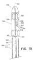
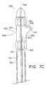
- FIGS. 7A-7Care cutaway views of a portion of the delivery system in FIG. 5A depicting a method of delivery of a branched vessel prosthesis.
- FIG. 1Ais a side view of a support frame 12 of a branched vessel prosthesis 10 in a bifurcated radially expanded configuration.
- the support frame 12includes a first primary hoop member 20 joined to a second primary hoop member 22 by a longitudinal connecting strut 30 .
- the term “primary hoop member”is used throughout the specification to refer to a generally circular (or elliptical) or cylindrical frame structure which resists compression by providing a desired level of radial rigidity after deployment.
- the primary hoop members 20 , 22are each in a radially expanded configuration and are longitudinally spaced from each other to define a primary lumen 40 around the longitudinal axis 6 .
- the support frame 12also includes a branch hoop member 54 connected to at least one primary hoop member by at least one flexible strut.
- FIGS. 1A and 1Billustrate this connection between the branch hoop member 54 and the first primary hoop member 20 by a first flexible connecting strut 60 and the second primary hoop member 22 by a second flexible connecting strut 62 .
- the branch hoop member 54is shown as a circumferentially enclosed structure defining a branch lumen 42 in communication with the primary lumen 40 .
- the support frame 12is moveable between the bifurcated radially expanded configuration and a radially compressed configuration shown in FIG. 1B . Movement from the radially expanded configuration to the radially compressed configuration may be performed in one or more independent steps, including: (1) lateral translation of the branch hoop member 54 radially inward toward the longitudinal axis 6 , (2) radial compression of the first primary hoop member 20 toward the longitudinal axis 6 and (3) radial compression of the second primary hoop member 20 toward the longitudinal axis 6 . These steps may be performed independent of each other or simultaneously, and may be performed while expanding or compressing the radial profile of the support frame 12 .
- the support frame 12can be deployed in stages within a body vessel, permitting adjustment of the relative longitudinal spacing of the primary hoop members 20 , 22 relative to one another during the deployment process.
- the primary hoop members 20 , 22remain connected by the longitudinal connecting strut 30 and are disposed around the longitudinal axis 6 .
- the branch hoop member 54is positioned within the primary lumen 40 between the compressed primary hoop members 20 , 22 to define a first position.
- the primary hoop members 20 , 22can be spaced a longitudinal distance 24 that can be greater than a diameter 56 of the branch hoop member 54 in the second position or the first position such that the branch hoop member is positionable between the primary hoop members.
- the branch hoop member 54can have a length 58 that is less than the diameter 26 of the primary hoop members 20 , 22 in the radially compressed configuration such that the branch hoop member is positionable within the primary lumen when the primary hoop members is in the radially compressed configuration.
- the branch hoop member 54remains connected to the first primary hoop member 20 by the first flexible connecting strut 60 , and to the second primary hoop member 22 by the second connecting strut 62 .
- the flexible connecting struts 60 , 62can be bowed inward to accommodate the positioning of the branch hoop member 54 at the first position.
- the branch hoop member 54is moveable between the first position shown in FIG. 1B and a second position shown in FIG. 1A , where the branch hoop member 54 is to be implanted outside the primary lumen 40 .
- the branch lumen 42defined within the branch hoop member 54 about a branch axis 8 which transverses the longitudinal axis 6 of the primary lumen 40 .
- the branch lumen 42can cross the primary lumen 40 at an angle A, as shown in FIG. 1A .
- the angle Ais determined by the angle between a primary body vessel and a secondary body vessel, or alternatively, the angle between the longitudinal axis and branch axis.
- the movement of the branch hoop memberis preferably independent of the radial expansion of the primary hoop members 20 , 22 .
- the branch hoop memberis shown to have a smaller cross-sectional area or diameter than the primary hoop members. It is appreciated that the branch hoop member size can be substantially identical to the size of the primary hoop members.
- the length 58 of the branch hoop memberis the distance between the distal and proximal ends of the frame structure of the branch hoop member. Preferably, the length 58 is about 25-75%, and most preferably about 30-50%, the diameter 26 of the primary hoop members in the radially compressed configuration.
- the a potion or all of the branch hoop member 32can be radially compressed in order to better fit within the branch lumen during deployment.
- the first and second flexible connecting struts 60 , 62are formed from a resilient material.
- the resilient materialprovides a bias, such that the branch hoop member 54 assumes the second position in the absence of a means for retaining and/or restraining the branch hoop member in the first position, as described below.
- the flexible connecting struts 60 , 62may be formed by a superelastic shape memory metal that is heat set in order to conform to the shape of flexible connecting struts 60 , 62 shown in FIG. 1A absent a means for retaining and/or restraining these structures in the configuration shown in FIG. 1B . Accordingly, the branch hoop member 54 may be deployed from the first position to the second position by self expansion of the flexible connecting struts 60 , 62 .
- the flexible connecting struts 60 , 62may include alternative structures, such as tubular graft material, as shown in FIG. 2C , and/or sutures.
- the connecting strutsare flexible to allow the branch hoop member to be positioned between the primary hoop members. The branch hoop member can then be implanted within the branch vessel.
- the flexible connecting struts 60 , 62can be arcuate, especially in the expanded configuration, in order to conform to the shapes of the primary and branch vessels.
- FIG. 1Aillustrates the flexible connecting strut 62 having a small radius of curvature sufficient to bend around the angle created by the branch vessel and place the branch hoop member 54 within the branch vessel.
- the flexible connecting strut 62may have one or more bends in order to define the position of the branch hoop member 54 within the branch vessel.
- the flexible connecting strut 60is illustrated having a larger radius of curvature than the connecting strut 62 , have one bend or multiple bends, to define the position of the branch hoop member 54 .
- the length of the flexible connecting strut 60is preferably longer than the length of the connecting strut 62 , although the length of the struts will depend on the geometry of the primary and branch vessels.
- the flexible connecting strutsmade of nitinol, are heat set to conform to the shape after insertion within the body.
- the primary hoop members 20 , 22 and the branch hoop member 54each may have an annular configuration selected or optimized for a particular application.
- the structure of these hoop membersis selected to provide a radially compressible annular structure that provides a desired degree of hoop strength.
- the structureshould be selected to provide a minimum desired amount of mechanical radial support to maintain patency of the primary lumen 40 and the branch lumen 42 upon implantation.
- these hoop structuresshould also provide a minimal desired amount of radial compressibility to prevent damage or undesirable levels of inflammation or irritation of tissue contacting the structure upon implantation.
- the size, material and configuration of these hoop membersmay be selected for a particular application and desired point of implantation within a body.
- these hoop membersmay be formed by a series of circumferentially connected hexagonal unit cells, as shown in FIGS. 1A and 1B .
- one or more of the hoop membersmay be formed as a sinusoidal or zigzag array of alternating struts and bends forming the circumferential hoop perimeter.
- Other configurations of the hoop membersare described below.
- a support frame 12is exemplified in FIGS. 1A and 1B with two primary hoop members 20 , 22 connected by one longitudinal connecting strut 30 and one branch hoop member 54
- other support frame embodimentsmay include any suitable number of these structures.
- a support framemay include one, three, four or more primary hoop members longitudinally spaced from each other and connected by any suitable number of longitudinal connecting members.
- the support framemay also include multiple branch hoop members extending in one, two or more directions from the longitudinal axis.
- each branch hoop membermay include multiple ring members if desired for a particular application.
- the primary hoop members 20 , 22 and the branch hoop member(s) 54may be the same or different in circumference and geometry.
- the support frame 12may include a pair of primary hoop members and a branch hoop member of the same or different sizes selected to fit within a body vessel at a point of treatment.
- Each branch hoop membermay be attached to each of the primary hoop members by a self-expanding flexible longitudinal connecting strut to permit the movement of the branch hoop member from the first position within the primary lumen between the primary hoop members to the second position outside the primary lumen by self-expansion of at least one of the primary longitudinal connecting struts.
- the primary and branch hoop membersalso can include structural features that facilitate anchoring, such as barbs, and structural features that facilitate visualization, such as radiopaque markers.
- the prosthesismay be a branched vessel prosthesis 100 preferably including a support frame 112 and a means for regulating fluid through a primary vessel 102 and at least one branch vessel 104 of the body vessel.
- the primary vessel 102 and the branch vessel 104can be example vessels found in deep veins, which have been known to bifurcate at one point and reconnect at another point.
- the branched vessel prosthesis 100may include one or more valve leaflets positioned and configured to regulate fluid passing through the primary vessel 102 and/or the branch vessel 104 .
- Alternative structures for regulating fluid flowmay include a flexible collapsible pocket structure or hinged member within a lumen area, and/or flexible covering material positioned around a portion of the support frame with a portion extending into a lumen and moveable for regulating fluid flow therein.
- the branched vessel prosthesis devicesare configured to treat incompetent or damaged cardiac or venous valves in mammals or to otherwise beneficially modify fluid flow in a bodily passage.
- a branched vessel prosthesismay be configured to replace or augment the function of natural venous valves operative in veins.
- the branched vessel prosthesispreferably includes a support frame designed to resist collapsing under the contraction of the muscle present around veins by symmetrically distributing stress and strain within the frame.
- blood flow in a veinoccurs in an intermittent nature, with surges in antegrade fluid flow occurring between intermittent retrograde fluid flow.
- a branched vessel prosthesis 100preferably provides a one-way valve that permits intermittent blood flow in an antegrade direction 106 B while inhibiting, that is reducing or preventing, the retrograde fluid flow in the opposite direction 106 A.
- the branched prosthetic valve 100is shown in the radially expanded configuration within the branch body vessel.
- the branched vessel prosthesis 100includes the support frame 112 that is similar to the support frames 12 , described herein.
- the support frame 112includes one or more primary hoop members, shown as primary hoop member 120 , 122 , to define a primary lumen 140 within the primary vessel 102 .
- the primary hoop members 120 , 122are similar in size as the primary vessel remains substantially similar in size.
- the primary hoop members 120 , 122are preferably spaced apart by a longitudinal distance. The distance is sufficient to provide adequate support just distal to the branch vessel 104 and just proximal to the branch vessel 104 . Preferably, the distance is also sufficient in order for a branch hoop member 154 , described below, to be received within the primary lumen 140 of the primary hoop members 120 , 122 .
- the primary hoop members 120 , 122are connected by one or more struts, shown as primary longitudinal connecting struts 130 , 131 .
- the struts 130 , 131can be spaced apart circumferentially by a distance sufficient to maintain the patency of the primary vessel 102 .
- Each of the primary hoop members 120 , 122are connected to the branch hoop member 154 by one or more struts, shown as flexible connecting struts 160 , 162 .
- the branch hoop member 154is positioned within the branch vessel 104 proximate the union with the primary vessel 102 .
- the branch hoop memberdefines a branch lumen 142 that is in communication with the primary lumen 140 .
- the branched vessel prosthesis 100also includes a valve, with a pair of valve leaflets 180 shown, although any number of leaflets can be used.
- the valve leafletsattach to the support frame 112 and extend from the support frame and across into the primary lumen 140 .
- the valve leafletis attached to the first primary hoop member 120 which is proximal to the second primary hoop member 122 , where the terms distal and proximal being relative to the operator.
- the second primary hoop member 122is generally closer to the heart.
- Each leaflet 180includes at least one edge to form a base 181 .
- the base 181is configured to attach to a primary hoop member 120 of the support frame 112 .
- Each leaflet 180also includes a flexible free edge 182 that is disposed within the primary lumen 140 .
- the flexible free edge 182 portion of the valve leaflets 180may be moveable between an open position shown in FIG. 2A and a closed position where the opposable free edge portions 182 contact one another. In the open position, the valve leaflets 180 may permit antegrade fluid flow through the primary lumen. In the closed position, the valve leaflets 180 may substantially prevent or reduce fluid flow in a retrograde direction opposite the antegrade direction through the primary lumen.
- the free edge of the valve leaflet in the open positioncan be distal to the branch lumen when the branched vessel prosthesis is in the branch radially expanded configuration and the branch hoop member is in the second position.
- the branch lumencan remain substantially unobstructed by the free edges of each of the valve leaflets when the branch vessel prosthesis is in the radially expanded configuration.
- the leaflets 180move back and forth in response to changes in fluid dynamic pressure.
- the leaflets 180When fluid is flowing through the primary vessel 102 in the normal, antegrade direction 106 B back to the heart, the leaflets 180 remain mostly open, moving freely within the primary lumen 140 to permit fluid flow in the antegrade direction 106 B.
- the leaflets 180move toward a closed position to prevent fluid flow in the retrograde direction 106 A.
- the valve leaflets 180also regulate fluid flow through the branched vessel 104 .
- the valve leaflets 180can permit fluid flow in a first direction 107 B, while collecting fluid flow in a second opposite direction 107 A on the one side of the valve leaflets 180 when in closed configuration.
- the first direction 106 B and/or 107 Bmay be an antegrade direction of blood toward the heart, while the second direction 106 A and/or 107 A may be a retrograde direction of blood away from the heart.
- the branched prosthetic valve 150includes the primary hoop member 120 and one or more branch hoop members, shown as branch hoop members 154 , 155 .
- One or more flexible connecting membersattach to the hoop members together.
- two primary connecting members 156 , 157extend between the primary hoop member 120 and each of the first and second branch hoop members 154 , 155 .
- a flexible connecting member 163can also connect the two branch hoop members 154 , 155 .
- the branch prosthetic valve 150forms a “Y”-shaped lumen having a primary lumen 141 and two branch lumens 143 , 145 .
- the primary hoop member 120is shown implanted within the primary vessel 102 , while the first and second branch hoop members 154 , 155 are shown implanted within the two branch vessels 103 , 104 .
- the first and second branch hoop members 154 , 155have the same or substantially similar structure.
- At least one of the first and second branch hoop members 154 , 155is moveable into the primary lumen 140 defined between the primary hoop member 120 and the other of the first and second branch hoop members 154 , 155 .
- One or more valve leaflets 180each can be attached to the primary hoop member 120 to extend into the “Y”-shaped primary lumen 140 to regulate fluid flow within the body vessel.
- valve leaflets 180permit fluid flow in the first antegrade direction 106 B along the primary vessel 102 and along the antegrade direction 107 B along the branch vessels 103 , 104 , while substantially preventing fluid flow in retrograde directions 106 A, 107 A.
- FIG. 2Canother example of the branched vessel prosthesis is shown, depicting a graft material as the means for attaching the branch hoop member to the primary hoop member.
- the graft materialcan be included in structures with the flexible connecting struts described in other embodiments for better sealing and/or coupling at the intersection of the vessels when vessels movement and sizes are less predictable.
- the branched vessel prosthesis 185is similar to the branched vessel prosthesis 100 except the branch hoop member 154 is attached to the primary hoop members 120 , 122 by a graft material 186 .
- the graft materialcan be fit within or over the branched vessel prosthesis having the flexible struts connecting the branch hoop member to the primary hoop member(s).
- the graft materialis conformable to a circular or arcuate shape in order to conform to the shape of the primary vessel 102 .
- the graft material 186is sized to minimize contact with the body vessel wall and to minimize the compression ratio of the primary hoop members in the compressed configuration.
- the graft material 186has a length sufficient for securable contact with the primary hoop members, with the illustrated length being to the ends of the hoop members.
- the graft material 186also has a fenestration 188 , where a second tubular member of graft material 190 is configured to attach to.
- the graft material 186 and the second graft material 190may be attached to one another with suturing or other attachment means known in the art.
- the second graft material 190has a cross-sectional area sized to fit with the branch vessel 104 .
- the graft material 186can attach to the primary hoop members 120 , 122 and/or the branch hoop member 154 by sutures, bio-adhesives, or other attachment means known in the art.
- the graft materialsare shown attached to outside of the respective hoop members, the graft material instead can be attached to the inside of the hoop members, or any combinations thereof.
- the graft material 186can include any suitable biocompatible synthetic and/or biological material, which is suitable for facilitating repair to the injured or diseased blood vessel.
- the graft materialmay be non-porous so that leakage from the graft material may be avoided under physiologic forces.
- the graft materialcan be made of woven DACRON® polyester (VASCUTEK® Ltd., Renfrewshire, Scotland, UK).
- the graft materialcan also be made of any other at least substantially biocompatible material including such materials as other polyester fabrics, polytetrafluoroethylene (PTFE), expanded PTFE, and other synthetic materials known to those of skill in the art.
- Naturally occurring biomaterialssuch as collagen
- ECMextracellular matrix
- SISsmall intestinal submucosa
- FIG. 3illustrates another example of the branched vessel prosthesis having valve leaflets attached in the primary hoop member and the branch hoop member.
- the branch vessel 104intersects the primary vessel 102 .
- the branched vessel prosthesis 200includes a pair of valves 202 , 204 .
- the first valve 202 of the pairis attached to at least one of the first and second primary hoop members 206 , 208 and the second valve 204 is attached to the branch hoop member 254 .
- the first and second primary hoop members 206 , 208can have the same or substantially similar structure.
- FIG. 4illustrates in more detail exemplary primary hoop members 206 , 208 of the branched vessel prosthesis 200 .
- the primary hoop members 206 , 208include a support frame 210 and at least one primary hoop member includes a valve 202 attached to the support frame 210 .
- the primary hoop member in FIG. 4depicts the support frame with a valve, preferably the primary hoop member 208 does not have a valve.
- the support frame 210is preferably a self-expandable support frame comprising proximal 214 and distal 216 portions connected by various connector segments 230 , 240 .
- the proximal portion 214defines a first serpentine path 218 that extends around the circumference of the support frame 210 .
- the distal portion 216defines a second serpentine path 220 that also extends around the circumference of the support frame 210 .
- Each serpentine path 218 , 220includes straight strut portions 222 that are interconnected by bends 224 .
- Each serpentine pathalso includes secondary bends 226 that substantially mirror the bends 224 on the path.
- the support frame 210advantageously includes conventional structural features that facilitate anchoring, such as barbs 228 , and structural features, such as radiopaque markers 229 , that facilitate visualization of the branched vessel prosthesis 200 in conventional or other medical visualization techniques, such as radiography, fluoroscopy, and other techniques.
- radiopaque makers 229are attached to the support frame and oriented such that the space between the primary hoop members is visual to indicate to the clinician where the branch hoop member is located during delivery, as shown in FIG. 3 .
- each of the connector segments 230 , 240include first and second struts that are substantially straight and disposed substantially parallel to each other.
- This arrangement of struts in the connector segments 230 , 240is considered advantageous at least because it provides a degree of structural redundancy and gives a secondary attachment point for the valve 202 along the length of the connector segments 230 , 240 .
- this secondary attachment pointcan be used at any point along the length of the segments 230 , 240 when a first attempt to pass through a partial thickness of the tissue is unsuccessful. This is particularly advantageous in valve devices in which the valve is attached to the support frame using one or more sutures.
- one connector segment 230defines an outwardly-projecting curve.
- the curveforces a part of the vessel wall outward, which defines a sinus at the point of implantation.
- This structural featureis considered advantageous at least because the provision of a sinus is believed to aid in the opening and closing of the valve 202 by creating flow patterns that facilitate movement of the free edge 276 of the leaflet 270 . This may enhance the overall performance of the branched vessel prosthesis. It is believed to be advantageous to attach the contiguous wall portion 272 of the valve 202 to the connector segment 230 defining the outwardly projecting curve.
- FIGS. 3 and 4include a support frame 210 having three connector segments 230 , 240 , 250 .
- Connector segment 230defines the curve, as described above, and is disposed substantially opposite to the inside surface of the leaflet 270 of the valve 202 .
- Connector segments 240 , 250are disposed substantially opposite to each other and near the attachment region 274 at which the leaflet 270 is attached to the contiguous wall portion 272 .
- the connector segments 240 , 250may lack the curve of the connector segment 230 and are disposed substantially parallel to each other. This structural arrangement ensures that the valve pocket formed when the valve 202 is in the closed configuration is not shallowly formed and that the leaflet 270 is able to sealingly interact with the vessel wall.
- the underside 282 of the support frame 210 of primary hoop member 206which represents the side disposed substantially opposite an exterior surface 278 of the leaflet 270 , preferably lacks a connector segment. Instead, this side 282 of the support frame 210 is largely open.
- This structural arrangementis considered advantageous at least because it enables the free edge 276 of the leaflet 270 to interact with the vessel wall during closure of the valve 202 , which is believed to result in better sealing and prevention of fluid flow in the reverse retrograde direction when the valve 202 is in the closed configuration.
- the underside of the support frame 210 of primary hoop member 208preferably includes a connector segment (not shown). This side of the support frame 210 of the primary hoop member 208 is enclosed with the connector segments circumferentially spaced.
- any suitable numbercan be used and the specific number chosen for a particular valve device according to an embodiment of the invention will depend on various considerations, including the nature and size of the valve 202 and the nature and size of the body vessel into which the valve device is intended to be implanted.
- the illustrated connector segmentsare disposed substantially equidistant from each other, it is noted that any suitable arrangement can be used and the specific arrangement chosen for a particular valve device according to an embodiment of the invention will depend on various considerations, including the nature and size of the valve 202 and the nature and size of the contiguous wall portion 272 of the valve 202 .
- the primary hoop members 206 , 208are shown implanted within the primary vessel 102
- the branch hoop member 254is shown implanted within the branch vessel 104 .
- the primary hoop members 206 , 208are connected to one another by one or more longitudinal connecting struts 232 , which define a primary lumen 242 within.
- the valve 202is attached to the support frame 210 in a manner such that the valve is normally open, i.e., the free edge 276 of the leaflet 270 is collapsed against the contiguous wall portion. This can allow fluid flow to pass through the lumen 242 of the valve device 200 and the vessel in which it is implanted. As best illustrated in FIG. 4 , the valve 202 closes only when a pressure head develops on an antegrade side 284 of the valve 202 that is sufficient to force the free edge 276 of the leaflet 270 away from the contiguous wall portion 272 and adjacent wall of the body vessel and toward, and potentially against, the opposing wall of the body vessel.
- a valve pocket 290is formed that fills with fluid until the valve 202 returns to its open configuration, which can occur in response to a change in the fluid pressure differential across the valve 202 , a change in fluid flow direction, or both.
- the first valve 202permit fluid flow in the first antegrade direction 205 B along the primary vessel 102 , while preventing fluid flow in the second retrograde direction 205 A.
- the branch hoop member 254is preferably connected to both primary hoop members 206 , 208 by flexible connecting members 262 , 263 as illustrated. However, the branch hoop member may be connected to only one of the primary hoop members by one or more flexible connecting members, by sutures, or by graft materials, as described above.
- the branch hoop member 254defines a branch lumen 244 that is in communication with the primary lumen 242 .
- the branch hoop member 254can have any of the frame structures described or shown in the specification.
- the valve 204can be any of the valve configurations described or shown in the specification.
- the branched vessel prosthesis 200may be used to prevent fluid flow from the primary lumen 242 into the branch lumen 244 and/or from the branch lumen into the primary lumen.
- the branch valve 204is attached to the branch hoop member 254 in a manner such that the valve is normally open, i.e., the free edge 286 of the leaflet 285 is collapsed against the contiguous wall portion. This can allow fluid flow to pass through the branch lumen 244 of the valve device 200 and the vessel in which it is implanted.
- the valve 204closes only when a pressure head develops on a side of the valve 204 that is sufficient to force the free edge 286 of the leaflet 285 away from the contiguous wall portion and adjacent wall of the body vessel and toward, and potentially against, the opposing wall of the body vessel for monocusp valves or other valve leaflets for multi-leaflet valves.
- the valve 204returns to its open configuration, which can occur in response to a change in the fluid pressure differential across the valve 204 , a change in fluid flow direction, or both.
- the second valve 204permits fluid flow in the second antegrade direction 207 B along the branched vessel 104 , into the primary lumen 242 , while substantially preventing fluid flow in retrograde directions 207 B. It is appreciated that it may be desirable to reorient the branch valve 204 in order to work oppositely, i.e., to prevent flow in the antegrade direction, while allowing fluid flow in the retrograde direction.
- the support frames described above, or any portion thereof,may be self-expanding, or alternatively, may be forcibly expandable (e.g., balloon-expandable).
- the support framemay be formed from any suitable material.
- Preferred materials for framesinclude those materials that can provide the desired functional characteristics with respect to mechanical load bearing, biological compatibility, modulus of elasticity, radio-opacity, or other desired properties.
- the materials used to form the implantable framescan comprise a material that exhibits excellent corrosion resistance.
- the materialcan be selected to be sufficiently radiopaque and create minimal artifacts during magnetic resonance imaging techniques (MRI).
- the implantable framecan comprise a metal, a metal alloy, a polymer, or any suitable combination thereof, for example as frame with multiple layers.
- the support framesare self-expanding comprising a material capable of significant recoverable strain to assume a low profile for delivery to a desired location within a body lumen.
- the frameAfter release of the compressed self-expanding stent, it is preferred that the frame be capable of radially expanding back to its original diameter or close to its original diameter.
- some examplesprovide frames made from material with a low yield stress (to make the frame deformable at manageable balloon pressures), high elastic modulus (for minimal recoil), and is work hardened through expansion for high strength.
- Particularly preferred materials for self-expanding implantable framesare shape memory alloys that exhibit superelastic behavior, i.e., are capable of significant distortion without plastic deformation.
- Frames manufactured of such materialsmay be significantly compressed without permanent plastic deformation, i.e., they are compressed such that the maximum strain level in the stent is below the recoverable strain limit of the material.
- Discussions relating to nickel titanium alloys and other alloys that exhibit behaviors suitable for framescan be found in, e.g., U.S. Pat. No. 5,597,378 to Jervis and PCT Publication WO 95/31945 (Burffle et al.), each of which is hereby incorporated by reference in its entirety.
- a preferred shape memory alloyis Ni—Ti, although any of the other known shape memory alloys may be used as well.
- Such other alloysinclude: Au—Cd, Cu—Zn, In—Ti, Cu—Zn—Al, Ti—Nb, Au—Cu—Zn, Cu—Zn—Sn, CuZn—Si, Cu—Al—Ni, Ag—Cd, Cu—Sn, Cu—Zn—Ga, Ni—Al, Fe—Pt, U—Nb, Ti—Pd—Ni, Fe—Mn—Si, and the like. These alloys may also be doped with small amounts of other elements for various property modifications as may be desired and as is known in the art.
- Nickel titanium alloys suitable for use in manufacturing implantable framescan be obtained from, e.g., Memry Corp., Bethel, Conn.
- Nitinola Nickel-Titanium alloy that can recover elastic deformations of up to 10 percent. This unusually large elastic range is commonly known as superelasticity.
- the materialcan be various types of spring metals.
- the flexible connecting struts connecting the branch hoop member to the primary hoop membersare made of nickel titanium alloys or other heat-settable materials, the flexible connecting struts can be heat set to assume the second positions. Accordingly, it is to be understood that the various lengths of the flexible connecting struts and the angles between the branch hoop member and the primary hoop members can be achieved.
- the implantable framesare designed to be expanded by a balloon or some other device (i.e., the frames are not self-expanding), and may be manufactured from an inert, biocompatible material with high corrosion resistance that can be plastically deformed at low-moderate stress levels, such as tantalum.
- the implantable framescan be deployed by both assisted (mechanical) expansion, e.g. balloon expansion, and self-expansion means.
- assisted (mechanical) expansione.g. balloon expansion
- self-expansion meanse.g. balloon expansion
- the implantable frameis made from materials that can be plastically deformed through the expansion of a mechanical assist device, such as by the inflation of a catheter based balloon. When the balloon is deflated, the frame can remain substantially in the expanded shape.
- stainless steeltitanium ASTM F63-83 Grade 1, niobium or high carat gold K 19-22.
- One widely used material for balloon expandable structuresis stainless steel, particularly 304 and 316L stainless steel. This material is particularly corrosion resistant with a low carbon content and additions of molybdenum and niobium. Fully annealed, stainless steel is easily deformable.
- Alternative materials for mechanically expandable structural frames that maintain similar characteristics to stainless steelinclude tantalum, platinum alloys, niobium alloys, and cobalt alloys.
- the support framemay be formed from or coated with other materials, such as polymers and bioabsorbable polymers may be included in or on the implantable support frames.
- the support frames or portions thereofcan optionally comprise material that permits identification of the position or orientation of the frame within a body passage.
- Radiopaque markersare advantageously positioned at one or more ends of the implantable frame to aid the physician in positioning the frame at a site inside a body vessel.
- portions of the implantable framecan include a radiopaque material that can be identified by X-rays.
- U.S. Pat. No. 6,409,752 to Boatman et al.incorporated herein by reference in its entirety, discloses various radiopaque materials that can be used in or on the implantable frames.
- the implantable framesmay be fabricated using any suitable method known in the art.
- the complete frame structureincluding the primary and branch hoop members and the respective connecting struts, is cut from a solid tube or sheet of material, and thus the frame would be considered a monolithic unit.
- Laser cutting, water-jet cutting and photochemical etchingare all methods that can be employed to form the structural frame from sheet and tube stock. Still other methods for fabricating the complete frame structure as previously disclosed would be understood by one of skill in the art.
- the framecan also be formed from wire using wire forming techniques, such as coiling, braiding, or knitting. By welding the wire at specific locations a closed-cell structure may be created. This allows for continuous production, i.e. the components of the implantable frame may be cut to length from a long wire mesh tube.
- an implantable frameis constructed from sheet, wire (round or flat) or tubing. The method of fabrication can be selected by one skilled in the art depending on the raw material used. Techniques for forming implantable frames are discussed, for example, in Dougal et al., “Stent Design: Implications for Restenosis,” Rev. Cardiovasc Med. 3 (suppl. 5), S16-S22 (2002), which is incorporated herein by reference in its entirety.
- Suitable support frames for use in medical devices according to the inventioninclude those described in U.S. Pat. No. 6,464,720 to Boatman et al.; U.S. Pat. No. 6,231,598 to Berry et al.; U.S. Pat. No. 6,299,635 to Frantzen; U.S. Pat. No. 4,580,568 to Gianturco; and U.S.
- a support framecan optionally be sterilized using any suitable technique known in the art, or equivalents thereto.
- an implantable framecan be sterilized using ethylene oxide sterilization, as described in AAM/ISO 11135:1994 “Medical Devices—Validation and Routine Control of Ethylene Oxide Sterilization,” incorporated herein by reference in its entirety.
- a sterilized implantable framesatisfies a minimum Sterility Assurance Level (SAL) of about 10 ⁇ 6 .
- SALSterility Assurance Level
- valve member or valve leafletA wide variety of materials acceptable for use as a valve member or valve leaflet are known in the art, and any suitable material can be utilized.
- the material chosenneed only be able to perform as described herein, and be biocompatible, or able to be made biocompatible. Examples of suitable materials include natural materials, and synthetic materials.
- valve deviceshaving two or more leaflets can be used in the valve devices according to the invention.
- a valvehaving two or more leaflets can be used in the valve devices according to the invention.
- a valvethat includes two or more leaflets attached to a contiguous wall portion.
- the contiguous wall portionneed not include any commissure(s) between the leaflets.
- Multi-leaflet valvesare advantageously attached to the support frame such that the free edges of the leaflets are able to coapt with each other such that the leaflets can close a valve opening formed inside the lumen of the valve device.
- the leafletis formed from a flexible material comprising a naturally derived or synthetic collagenous material, and especially an extracellular collagen matrix material.
- suitable natural materialsinclude collagen and extracellular matrix (ECM) material, such as submucosa.
- ECMextracellular matrix
- the extracellular matrixis typically a collagen-rich substance that is found in between cells in animal tissue and serves as a structural element in tissues.
- Such an extracellular matrixis preferably a complex mixture of polysaccharides and proteins secreted by cells.
- the extracellular matrixcan be isolated and treated in a variety of ways. Following isolation and treatment, it is referred to as an ECM.
- ECMmay be isolated from submucosa (including small intestine submucosa), stomach submucosa, urinary bladder submucosa, tissue mucosa, renal capsule, dura mater, liver basement membrane, pericardium, serosa, and peritoneum or other tissues.
- SISsmall intestine submucose
- SIShas been used successfully in vascular grafts, urinary bladder and hernia repair, replacement and repair of tendons and ligaments, and dermal grafts.
- SISis particularly well-suited for use as valve members, such as leaflets.
- the ECM materialis porcine SIS.
- SIScan be prepared according to the method disclosed in U.S. 2004/0180042A1, the contents of which are incorporated herein by reference in its entirety.
- autologous tissuecan be harvested as well.
- Elastin or Elastin Like Polypeptides (ELPs) and the likeoffer potential as a material to fabricate the flexible covering or discrete shaping members to form a device with exceptional biocompatibility.
- Another alternativeis use of allographs such as harvested native valve tissue. Such tissue is commercially available in a cryopreserved state.
- the valve leafletmay be formed from a synthetic polymeric material.
- suitable polymeric materialsinclude polyesters, such as poly(ethylene terephthalate), polylactide, polyglycolide and copolymers thereof; fluorinated polymers, such as polytetrafluoroethylene (PTFE), expanded PTFE and poly(vinylidene fluoride); polysiloxanes, including polydimethyl siloxane; and polyurethanes, including polyetherurethanes, polyurethane ureas, polyetherurethane ureas, polyurethanes containing carbonate linkages and polyurethanes containing siloxane segments.
- the valve leaflet materialmay be a biocompatible polyurethane or derivative thereof.
- biocompatible polyurethaneis THORALON (THORATEC, Pleasanton, Calif.), as described in U.S. Pat. Application Publication No. 2002/0065552 A1 and U.S. Pat. No. 4,675,361, both of which are incorporated herein by reference.
- materials that are not inherently biocompatiblemay be subjected to surface modifications in order to render the materials biocompatible.
- surface modificationsinclude graft polymerization of biocompatible polymers from the material surface, coating of the surface with a crosslinked biocompatible polymer, chemical modification with biocompatible functional groups, and immobilization of a compatibilizing agent such as heparin or other substances.
- a xenogeneic valveis harvested and fixed using suitable techniques, such as by fixing the valve with gluteraldehyde or any other suitable cross-linking agent.
- suitable fixation techniquesare described in U.S. Pat. No. 4,800,603 to Jaffe; U.S. Pat. No. 5,595,571 to Jaffe and Hancock; U.S. Pat. No. 5,720,777 to Jaffe and Hancock; U.S. Pat. No. 5,843,180 to Jaffe and Hancock; and U.S. Pat. No. 5,843,181 to Jaffe and Hancock, each of which is hereby incorporated by reference in its entirety for the purpose of describing suitable techniques for fixing a xenogeneic valve for inclusion in a valve device according to the disclosure.
- a second step of the exemplary method of making valve devices suitable for implantation in a patientcomprises attaching the valve to a support frame.
- the step attaching the valve to a support frameis accomplished by connecting the valve to the support frame using a single suture.
- valve leafletmay be formed on the support structure by an appropriate means, including but not limited to vapor deposition, spraying, electrostatic deposition, ultrasonic deposition, or dipping.
- One or more valve leafletscan be attached to the support frame by other methods.
- a sheet of materialis cut to form a valve leaflet and the edges of the leaflet are wrapped around portions of a support frame and portions of the valve leaflet sealably connected together to fasten the valve leaflet around the support frame.
- one edge of a sheet of valve leaflet materialcan be wrapped around a portion of the support frame and held against the body of the valve leaflet, so that the valve leaflet material forms a lumen enclosing a portion of the support frame.
- a small amount of a suitable solventis then applied to the edge of the valve leaflet material to dissolve the edge into an adjacent portion of the valve leaflet material and thereby seal the material around the support frame.
- the sheet of valve leaflet materialis shaped to form the valve leaflet that is attached to a portion of a support frame using stitching through the valve leaflet material and around a portion of the support structure, adhesives, tissue welding or cross linking to directly join the valve leaflet material to the support frame.
- a valve leaflet attached to a support framecan be permitted to move relative to the support frame, or the valve leaflet can be substantially fixed in its position or orientation with respect to the support frame by using attachment configurations that resist relative movement of the valve leaflet and the support frame.
- Examples of other implantable valves, and their preparation, for inclusion in devices according to the inventioninclude U.S. patent application Ser. No. 12/252,253, filed on Oct.
- intraluminal prosthesis delivery systemsare provided.
- the delivery systemincludes a catheter and one embodiment of the branched prosthetic valve or frames described above.
- the various embodiments of the branched vessel prosthesiscan be compressed to the radially compressed configuration, as described with reference to FIGS. 1A and 1B .
- the branched vessel prosthesisis compressed within the primary lumen defined by the compressed primary hoop members and enclosed by a retaining sheath at or near the distal end of a delivery catheter.
- the branched vessel prosthesiscan be expanded, for example, by removing the retaining sheath, or portion thereof, and/or inflating a balloon from inside the branch vessel prosthesis to radially expand one or more primary hoop members.
- the delivery systemmay include a means for retaining and/or releasing the branch hoop member.
- the delivery configurationcan be maintained prior to deployment of the branch vessel prosthesis by any suitable means, including a sheath, a suture, a tube or other restraining material around all or part of the compressed branch vessel prosthesis, or by other methods.
- FIGS. 5A-5Cshow a portion a delivery system 300 , showing the distal end of a delivery catheter 302 having a longitudinal axis 306 extending from a proximal end (not shown) to a tapered tip 308 at the distal end 310 .
- the delivery catheter 302includes an outer sheath 312 enclosing an inner shaft 314 defining a wire guide lumen.
- the inner shaft 314may have an additional channel 317 for receiving a wire member of a tether system or trigger wire system, as describe below.
- the outer sheath 312is translatable along the longitudinal axis 306 relative to the inner shaft 314 .
- a branched vessel prosthesis 320 in a radially compressed configurationis disposed in a space 316 defined between a portion of the inner shaft 314 and the outer sheath 312 , as shown in FIGS. 5C-D .
- the branched vessel prosthesis 320may have any configuration described with respect to the embodiments described above.
- the branch vessel prosthesis 320includes a pair of longitudinally spaced primary hoop members 322 , 324 in a radially compressed configuration within the outer sheath 312 about the inner shaft 314 .
- the primary hoop members 322 , 324are joined by one or more primary longitudinal connecting struts 330 .
- the branched vessel prosthesis 320also includes a branch hoop member 332 positionable in a first position between the pair of primary hoop members 322 , 324 .
- the branch hoop member 322can be connected by one or more flexible connecting members, shown as 332 , 336 , suture or graft materials.
- the branch hoop memberWhen the branch hoop member is in the first position, the branch hoop member is positioned between the surfaces of the outer sheath 312 and the inner shaft 314 , but not coaxially around the inner shaft 174 .
- the delivery system 300also includes a means for retaining the branch hoop member 332 in the first position.
- the retaining meansmay include a mechanical tether 340 .
- the mechanical tether 340includes a control member 341 , such as a wire or tube, extending from the proximal portion of the delivery catheter (not shown) to a distal hook portion 342 .
- the hook portion 342is configured to receive one or more proximal apices 343 (or distal apices) of the struts of the branch hoop member 332 .
- the mechanical tether 340When the mechanical tether 340 is coupled to the proximal apices 343 , the mechanical tether 340 can be put under tension and locked by conventional means at the proximal portion in order to fix the branch hoop member 332 to the first position. After unlocking the proximal portion, the proximal end of the mechanical tether 340 can be manipulated such that the hook portion 342 is removed from attachment with the proximal apices 343 to free the branch hoop member 332 , thereby allowing the branch hoop member to move freely from the first position to the second position.
- the hook portion 342can be removed from attachment by sliding the mechanical tether in the distal direction until the hook portion 342 is removed from contact with the proximal apices 343 .
- the radial expansion of the primary hoop members 322 , 324can be performed independently from the transverse extension of the branch hoop member 332 away from the longitudinal axis 306 .
- the apices or apertures of the branch hoop membercan have a loop to bring the respective apices together as described below.
- the retaining meansmay include a trigger wire system 350 including a control member 351 , such as a wire or tube, and a distal portion 352 coupled to the apices or apertures of the struts of the branch hoop member 332 .
- the control member 351can have a distal end that is removably attached to the tapered tip 308 .
- the distal portion 352can be inserted through at least one apex in order to retain the branch hoop member 332 , shown as a zigzag stent, within the first position.
- the branch hoop member shown in all of the figuresmay have apertures for receiving a suture 339 (proximal) or 347 (distal) disposed at one or more of the apices.
- the suturecan be attached to the apices or the apertures, proximal and/or distal, by wrapping around or tying a knot in order to maintain a circular or elliptical shape while the branch hoop member radially expands in the second position.
- the control member 351can be removed from contact with the apices or apertures by conventional means.
- the distal apices 345may also includes a second retaining means 360 , as shown in FIGS. 6B and 6D , including a retaining ring 362 running through at least one apex or aperture to draw or gather the apices together in order to retain and/or maintain the branch hoop member in the radially compress configuration, especially after moving to the second position.
- the retaining ring 362is preferably a ring of semi-rigid to rigid biocompatible material having ends that overlap sufficiently to provide retention force to keep the apices together and to permit removal of the ring from the apices.
- At least a portion of the retaining ring 362may also be tapered in order to provide more strength to the ring where the control member attaches and less strength at the overlap for easier removal.
- the retaining ring 362can be removed from the apices in order for the apices of the branch hoop member to radially expand against the vessel.
- the retaining ring 362can be attached to a second trigger wire system via a connecting member 361 so that retraction of the control member of the second trigger wire system up to a certain point removes the retaining loop 362 from contact with the apices 345 . This can allow the branch hoop member to move to the second position.
- the retaining ringcan be independently removed from contact with the branch hoop member integrally with the removal of the control member of the trigger wire system 350 .
- the coupling of the retaining ring to the apices and the rigidity of the connecting member 361may be sufficiently strong in order to urge the branch hoop member into the branch vessel if there are issues in deploying and/or urge the branch hoop member back into position between the primary hoop members for repositioning.
- the distal portion 352 of the trigger wiremay includes a loop 353 running through at least one apex that is coupled to the control member 351 . Accordingly, removal of the control member 351 urges the loop to decouple from the branch hoop member.
- FIG. 6Dillustrates another means for retaining. Instead of attaching to the proximal apices 343 as described in FIGS. 6B and 6C , the distal portion 353 of the control member or loop is attached to the distal apices 345 .
- the distal apices 345may also include the retaining ring 362 running through at least one apex or aperture to draw or gather the apices together in order to retain and/or compress the branch hoop member after being inverted, as shown in FIG. 6D .
- the flexible strut members 334 , 336remain against the sheath.
- the connecting member 361can be manipulated in order to urge the distal apices 345 to unfold.
- the connecting member 361can again be manipulated to decouple from the distal apices 345 in order for the distal apices to radially expand-within the branch vessel.
- retaining meanssuch as a mechanical tether, a trigger wire system, and/or second retaining means, as described above, such as a mechanical tether attached to the distal apices.
- a loop systemis described in U.S. Pat. No. 6,695,875, which is hereby incorporated by reference in its entirety.
- a plurality of loops attached to the branch hoop member and coupled to the retaining meanscan be configured to radially compress the branch hoop member.
- a first loop 371can be wrapped around the branch hoop member 332 in a first direction to radially compress the branch hoop member to a smaller diameter
- a second loop 372can be wrapped around in a second direction opposite the first.
- a loop 373 or control membercan be inserted therein to maintain the radially compressed configuration of the branch hoop member 332 .
- the loop 373having a length for permitting movement of the branch hoop member to the second position.
- Removal of the loop 373 or control member from the end of the loops 371 , 372causes the branch hoop member 332 to radially expand.
- the removal of the loop 373is advantageous after the branch hoop member is in the second position.
- a second trigger wire systemcan be used to remove the loop. Similar arrangements of loops to compress or reduce the diameter of the branch hoop member are described in U.S. Publs. 2007/0043425A1 and 2008/0294234, which are incorporated herein by reference in their entirety.
- the delivery system 300can have a circular cross section for orienting and deploying the branch hoop member 332 .
- the delivery catheter 302or a portion thereof, can also have a circular cross section perpendicular to the longitudinal axis 306 .
- the outer sheath 312may have a circular cross section, as shown in FIGS. 5B and 5C .
- FIG. 5Bshows the cross section of the delivery system of FIG. 5A along line 5 B- 5 B
- FIG. 5Cshows the cross section of the delivery system of FIG. 5A along line 5 C- 5 C.
- the outer sheath 312encloses the inner shaft 314 , which defines a wire guide lumen 315 .
- the inner shaft 314can have an elliptical cross section, but may have any suitable shape.
- the wire guide lumen 315is preferably circular and sized to slidably enclose a suitable wire guide.
- a series of strut cross sections 324 A of the primary hoop member 324are disposed around the inner shaft 314 .
- the delivery system, the outer sheath and/or the inner shaftmay have an elliptical cross-section, as shown in FIG. 5D , but could be oblong, oval, egg-shaped or the like.
- the elliptical cross-section of the outer sheath 312has a first distance 348 A in a first direction 306 A (minor axis) and a second distance 348 B in a second direction 306 B (major axis) perpendicular to the first direction.
- the first and second directions 306 A, 306 Bare perpendicular to the longitudinal axis 306 .
- the second distance 348 Bis greater than the first distance 348 A.
- FIG. 5Cillustrates a cross section 330 A of the primary longitudinal connecting strut and two cross sections 332 A of the branch hoop member 332 that are disposed between the inner shaft 314 and the outer sheath 312 .
- the branch hoop member in the first positionis preferably positioned along the second radial direction (major axis) to take advantage of the additional distance provided by the second distance.
- the positioning and delivery of the branch hoop member 332 within a body vesselmay be performed easier with radiopaque marker strips 349 , as shown in FIG. 5C , although other types of imagable means known in the art may be used.
- the strips 349are positioned along the interior surface of the outer sheath 312 or exterior surface of the inner shaft 314 .
- the strips 349can be strategically placed such that rotating the delivery catheter around the longitudinal axis 306 changes the apparent width of the outer sheath 312 in a two-dimensional planar representation of the delivery catheter, such as an x-ray or fluoroscopic image.
- two strips 349can be placed at diametrically opposite ends.
- the direction of deployment of the branch hoop member 332can be oriented prior to deployment of the branch hoop member 332 .
- the strips 349can be positioned along the interior wall of the outer sheath at the intersection between the major axis and/or minor axis and the outer sheath to further enhance the detection of the orientation of the branch hoop member.
- branched vessel deviceis preferably delivered from a percutaneous catheter according to the second embodiment.
- the branched vessel prosthesismay include a valve, as described above.
- the branched vessel prosthesisis preferably adapted for transcatheter percutaneous delivery.
- the branched vessel prosthesiscan be moveable from a compressed delivery state suitable for introduction to a point of treatment with a catheter delivery system, to a radially expanded implanted state for retention within the body vessel at the point of treatment therein.
- Branched vessel prosthesiscan be deployed in a body lumen by means appropriate to their design.
- the branched vessel prosthesiscan be adapted for deployment using conventional methods known in the art and employing percutaneous transluminal catheter devices.
- the branched vessel prosthesisis designed for deployment by any of a variety of in situ expansion means.
- the branched vessel prosthesismay be mounted onto a delivery catheter that holds the branched vessel prosthesis as it is delivered through the body lumen.
- the branched vessel prosthesismay then be translated through a body to a point of treatment by advancing the catheter over a wire guide to the location of the point of treatment.
- the branched vessel prosthesiscan be released and allowed to self-expand into contact with the body vessel wall.
- the prosthesiscan be released by withdrawing an outer sheath from over the branched vessel prosthesis.
- the branched vessel prosthesismay be deployed by radial expansion of the primary hoop member(s) within a primary vessel and extension of the branch hoop member(s) into a branch vessel at the point of treatment.
- the catheter, sleeve, and guidewiremay then be removed from the patient. This deployment is effected after the branched vessel prosthesis has been introduced percutaneously, transported transluminally and positioned at a desired location by means of the catheter.
- the systemmay be configured to retain a branched vessel prosthesis in the radially compressed configuration with the branch hoop member positioned between the pair of radially compressed primary hoop members.
- the systemis adapted to permit expansion of individual primary hoop members and lateral extension of the branch hoop member independent of each other.
- the delivery systemmay include a delivery catheter with a distal portion adapted to receive and retain the branched vessel prosthesis in the radially compressed configuration.
- the branched vessel prosthesiscan be deployed in stages within a body vessel, permitting adjustment of the relative longitudinal spacing of the primary hoop members relative to one another during the deployment process.
- FIGS. 7A-7Cshow the deployment of the branched vessel prosthesis from the delivery system 300 shown in FIGS. 5A-5C .
- the outer sheath 312is translated in a proximal direction relative to the inner shaft 314 and the branched vessel prosthesis 320 , away from the tip portion 308 .
- FIG. 5ATo deploy a branched vessel prosthesis 320 in a radially compressed configuration shown in FIG. 5A , the outer sheath 312 is translated in a proximal direction relative to the inner shaft 314 and the branched vessel prosthesis 320 , away from the tip portion 308 .
- the outer sheath 312is translated in a proximal direction past a radially self-expanding first primary hoop member 324 , permitting the radial expansion of the first primary hoop member 324 as shown.
- the second primary hoop member 322remains in the radially compressed configuration.
- the branch hoop member 332remains in the first position, restrained by the proximal portion 342 of the mechanical tether 340 .
- the flexible longitudinal connecting struts 334 , 336can extend from the primary hoop members 322 , 324 to the branch hoop member 332 .
- the two primary hoop members 322 , 324can be joined by one or more primary longitudinal connecting struts 330 .
- FIG. 7Bshows the subsequent outer sheath 312 retracted proximally away from the branched vessel prosthesis 320 , permitting radial self expansion of both the primary hoop members 322 , 324 to define a primary lumen therebetween.
- the branch hoop member 332remains in the first position between the primary hoop members 322 , 324 , restrained by the proximal portion 342 of the mechanical tether 340 , or other retaining means discussed above.
- the inner diameter of the radially expanded primary hoop members 322 , 324is preferably larger than the maximum diameter of the tip 308 , the outer sheath 312 around the inner shaft 314 .
- the branch hoop member 332 in the first positionremains to one side of the longitudinal axis 306 of the delivery catheter.
- the branch hoop member 332may be extended in a direction away from the longitudinal axis 306 as shown in FIG. 7C by manipulating the mechanical tether 340 so as to release the branch hoop member 332 from the first position ( FIG. 7B ) to the second position in FIG. 7C .
- the flexible longitudinal connecting struts 334 , 336are preferably configured to self expand in a manner to translate the branch hoop member 332 toward the second position upon release of the mechanical tether 340 .
- the branch hoop member 332is released into a branched vessel at a point of treatment.
- the outer sheath 312may be translated along the longitudinal axis relative to the inner shaft 314 toward the tip 308 .
- the delivery cathetermay subsequently be removed from the body vessel, leaving the branched vessel prosthesis at a branched vessel.
- the methodmay also include one or more of the following steps: determining the size of the first body vessel and the second body vessel; assembling the support frame in the expanded configuration by selecting the primary hoop members sized to fit within the first body vessel at the point of treatment, and attaching the at least one primary longitudinal strut to connect the primary hoop members, and selecting the branch hoop member sized to fit within the second body vessel at the point of treatment, and attaching the at least one flexible strut to the branch hoop member to connect the branch hoop member to at least one primary hoop member to form the branched vessel prosthesis in the branch expanded configuration with the branch hoop member in the second position; translating the branch hoop member from the second position to the first position by bending the at least one flexible strut; radially compressing the branched vessel prosthesis into the compressed configuration while maintaining the branch hoop member in the first position prior to inserting the branched vessel prosthesis into the body.
- the branched vessel prosthesis as described hereinmay be delivered to any suitable body vessel, such as a vein, artery, biliary duct, ureteral vessel, body passage or portion of the alimentary canal. While many preferred embodiments discussed herein discuss implantation of a branched vessel prosthesis in a vein, other embodiments provide for implantation within other body vessels. In another matter of terminology there are many types of body canals, blood vessels, ducts, tubes and other body passages, and the term “vessel” is meant to include all such passages. In some embodiments, branched vessel prosthesis having a compressed delivery configuration with a very low profile, small collapsed diameter and great flexibility, may be able to navigate small or tortuous paths through a variety of body vessels.
- a low-profile branched vessel prosthesismay also be useful in coronary arteries, carotid arteries, vascular aneurysms, and peripheral arteries and veins (e.g., renal, iliac, femoral, popliteal, sublavian, aorta, intercranial, etc.).
- Other nonvascular applicationsinclude gastrointestinal, duodenum, biliary ducts, esophagus, urethra, reproductive tracts, trachea, and respiratory (e.g., bronchial) ducts.
- the configuration of the branched vessel prosthesismay be selected for a particular method of treatment.
- vesselsare generally more compliant and typically experience dramatic changes in their cross-sectional shape during routine activity.
- Medical devices for implantation in the peripheral vasculatureshould retain a degree of flexibility to accommodate these changes of the vasculature.
- medical devices according to the invention intended for implantation in the peripheral vasculaturesuch as prosthetic venous valves, advantageously include a self-expandable support frame.
- the prosthetic branched vessel devices of the first embodimentare desirably adapted for deployment within the vascular system, and in certain preferred embodiments, are adapted for deployment within the venous system.
- a prosthetic branched vessel devicemay be configured as a venous valve, for example, for placement within veins of the legs or feet, to treat venous insufficiency.
- the medical devicescan be placed in any medically appropriate location for a given application.
- the medical devicecan serve as part of a venous valve prosthetic and be implanted in the femoral vein, including at the proximal (groin), mid (mid section) or distal (adjacent to the knee) portions of the vein.
- the methods and devices described hereinare useful in treating a variety of medical conditions, including methods of treating conditions related to undesirable levels of retrograde fluid flow across a valve within a body cavity, especially near a branched site, such as venous valve related condition.
- Other areas of treatmentare in bifurcated veins that split or form to bypass thrombosed regions of a primary vessel and reconnect at another point and the junction of the deep vein or superficial veins and secondary and/or collateral veins.
Landscapes
- Health & Medical Sciences (AREA)
- Engineering & Computer Science (AREA)
- Biomedical Technology (AREA)
- Cardiology (AREA)
- Heart & Thoracic Surgery (AREA)
- Transplantation (AREA)
- Oral & Maxillofacial Surgery (AREA)
- Vascular Medicine (AREA)
- Life Sciences & Earth Sciences (AREA)
- Animal Behavior & Ethology (AREA)
- General Health & Medical Sciences (AREA)
- Public Health (AREA)
- Veterinary Medicine (AREA)
- Prostheses (AREA)
Abstract
Description
Claims (16)
Priority Applications (1)
| Application Number | Priority Date | Filing Date | Title |
|---|---|---|---|
| US12/425,911US8128686B2 (en) | 2008-04-18 | 2009-04-17 | Branched vessel prosthesis |
Applications Claiming Priority (2)
| Application Number | Priority Date | Filing Date | Title |
|---|---|---|---|
| US4621108P | 2008-04-18 | 2008-04-18 | |
| US12/425,911US8128686B2 (en) | 2008-04-18 | 2009-04-17 | Branched vessel prosthesis |
Publications (2)
| Publication Number | Publication Date |
|---|---|
| US20090264991A1 US20090264991A1 (en) | 2009-10-22 |
| US8128686B2true US8128686B2 (en) | 2012-03-06 |
Family
ID=40668287
Family Applications (1)
| Application Number | Title | Priority Date | Filing Date |
|---|---|---|---|
| US12/425,911ActiveUS8128686B2 (en) | 2008-04-18 | 2009-04-17 | Branched vessel prosthesis |
Country Status (4)
| Country | Link |
|---|---|
| US (1) | US8128686B2 (en) |
| EP (1) | EP2293745A1 (en) |
| AU (1) | AU2009236062A1 (en) |
| WO (1) | WO2009129481A1 (en) |
Cited By (64)
| Publication number | Priority date | Publication date | Assignee | Title |
|---|---|---|---|---|
| US20100268327A1 (en)* | 2009-04-17 | 2010-10-21 | Medtronic Vascular, Inc. | Mobile External Coupling for Branch Vessel Connection |
| US20110319991A1 (en)* | 2008-06-06 | 2011-12-29 | Edwards Lifesciences Corporation | Low Profile Transcatheter Heart Valve |
| US8790397B2 (en)* | 2007-04-23 | 2014-07-29 | Megumi MATHISON | Replacement heart valve, valve holder and methods of making same |
| US9132025B2 (en) | 2012-06-15 | 2015-09-15 | Trivascular, Inc. | Bifurcated endovascular prosthesis having tethered contralateral leg |
| US9999501B2 (en)* | 2012-04-18 | 2018-06-19 | Medtronic CV Luxembourg S.a.r.l. | Valve prosthesis |
| US10413406B2 (en) | 2007-12-14 | 2019-09-17 | Edwards Lifesciences Corporation | Leaflet attachment frame for a prosthetic valve |
| US10433958B2 (en) | 2010-10-05 | 2019-10-08 | Edwards Lifesciences Corporation | Prosthetic heart valve |
| US10463484B2 (en) | 2016-11-17 | 2019-11-05 | Edwards Lifesciences Corporation | Prosthetic heart valve having leaflet inflow below frame |
| US10470871B2 (en) | 2001-12-20 | 2019-11-12 | Trivascular, Inc. | Advanced endovascular graft |
| US10492910B2 (en) | 2015-10-13 | 2019-12-03 | Venarum Medical, Llc | Implantable valve and method |
| US10517722B2 (en) | 2016-03-24 | 2019-12-31 | Edwards Lifesciences Corporation | Delivery system for prosthetic heart valve |
| US10561494B2 (en) | 2011-02-25 | 2020-02-18 | Edwards Lifesciences Corporation | Prosthetic heart valve delivery apparatus |
| US10595993B2 (en) | 2013-12-05 | 2020-03-24 | Edwards Lifesciences Corporation | Method of making an introducer sheath with an inner liner |
| US10603165B2 (en) | 2016-12-06 | 2020-03-31 | Edwards Lifesciences Corporation | Mechanically expanding heart valve and delivery apparatus therefor |
| US10722353B2 (en) | 2017-08-21 | 2020-07-28 | Edwards Lifesciences Corporation | Sealing member for prosthetic heart valve |
| US10898319B2 (en) | 2017-08-17 | 2021-01-26 | Edwards Lifesciences Corporation | Sealing member for prosthetic heart valve |
| US10918473B2 (en) | 2017-07-18 | 2021-02-16 | Edwards Lifesciences Corporation | Transcatheter heart valve storage container and crimping mechanism |
| US10932903B2 (en) | 2017-08-15 | 2021-03-02 | Edwards Lifesciences Corporation | Skirt assembly for implantable prosthetic valve |
| US10940167B2 (en) | 2012-02-10 | 2021-03-09 | Cvdevices, Llc | Methods and uses of biological tissues for various stent and other medical applications |
| US10945837B2 (en) | 2013-08-12 | 2021-03-16 | Mitral Valve Technologies Sarl | Apparatus and methods for implanting a replacement heart valve |
| US10973629B2 (en) | 2017-09-06 | 2021-04-13 | Edwards Lifesciences Corporation | Sealing member for prosthetic heart valve |
| US10973631B2 (en) | 2016-11-17 | 2021-04-13 | Edwards Lifesciences Corporation | Crimping accessory device for a prosthetic valve |
| US11013595B2 (en) | 2017-08-11 | 2021-05-25 | Edwards Lifesciences Corporation | Sealing element for prosthetic heart valve |
| US11013600B2 (en) | 2017-01-23 | 2021-05-25 | Edwards Lifesciences Corporation | Covered prosthetic heart valve |
| US11026781B2 (en) | 2017-05-22 | 2021-06-08 | Edwards Lifesciences Corporation | Valve anchor and installation method |
| US11083575B2 (en) | 2017-08-14 | 2021-08-10 | Edwards Lifesciences Corporation | Heart valve frame design with non-uniform struts |
| US11147667B2 (en) | 2017-09-08 | 2021-10-19 | Edwards Lifesciences Corporation | Sealing member for prosthetic heart valve |
| US11185406B2 (en) | 2017-01-23 | 2021-11-30 | Edwards Lifesciences Corporation | Covered prosthetic heart valve |
| US11318011B2 (en) | 2018-04-27 | 2022-05-03 | Edwards Lifesciences Corporation | Mechanically expandable heart valve with leaflet clamps |
| US11324618B2 (en) | 2017-02-28 | 2022-05-10 | Cook Medical Technologies Llc | Delivery system for a preloaded fenestrated device having a ratcheted wire release |
| US11376145B2 (en) | 2017-10-31 | 2022-07-05 | Bolton Medical, Inc. | Distal torque component, delivery system and method of using same |
| US11399932B2 (en) | 2019-03-26 | 2022-08-02 | Edwards Lifesciences Corporation | Prosthetic heart valve |
| US11406493B2 (en) | 2014-09-12 | 2022-08-09 | Mitral Valve Technologies Sarl | Mitral repair and replacement devices and methods |
| US11406495B2 (en) | 2013-02-11 | 2022-08-09 | Cook Medical Technologies Llc | Expandable support frame and medical device |
| US11446169B2 (en) | 2017-03-10 | 2022-09-20 | The Cleveland Clinic Foundation | Bifurcated implant delivery system |
| US11446141B2 (en) | 2018-10-19 | 2022-09-20 | Edwards Lifesciences Corporation | Prosthetic heart valve having non-cylindrical frame |
| US11654023B2 (en) | 2017-01-23 | 2023-05-23 | Edwards Lifesciences Corporation | Covered prosthetic heart valve |
| US11730584B2 (en) | 2017-02-24 | 2023-08-22 | Bolton Medical, Inc. | System and method to radially constrict a stent graft |
| US11730589B2 (en) | 2010-03-05 | 2023-08-22 | Edwards Lifesciences Corporation | Prosthetic heart valve having an inner frame and an outer frame |
| US11779454B2 (en) | 2017-02-24 | 2023-10-10 | Bolton Medical, Inc. | Vascular prosthesis with crimped adapter and methods of use |
| US11857411B2 (en) | 2017-08-18 | 2024-01-02 | Edwards Lifesciences Corporation | Pericardial sealing member for prosthetic heart valve |
| US11883281B2 (en) | 2017-05-31 | 2024-01-30 | Edwards Lifesciences Corporation | Sealing member for prosthetic heart valve |
| US11963871B2 (en) | 2020-06-18 | 2024-04-23 | Edwards Lifesciences Corporation | Crimping devices and methods |
| US12004947B1 (en) | 2021-01-20 | 2024-06-11 | Edwards Lifesciences Corporation | Connecting skirt for attaching a leaflet to a frame of a prosthetic heart valve |
| US12029644B2 (en) | 2019-01-17 | 2024-07-09 | Edwards Lifesciences Corporation | Frame for prosthetic heart valve |
| US12048622B2 (en) | 2017-02-24 | 2024-07-30 | Bolton Medical, Inc. | Vascular prosthesis with moveable fenestration and method of use |
| US12083030B2 (en) | 2017-02-24 | 2024-09-10 | Bolton Medical, Inc. | Stent graft delivery system with constricted sheath and method of use |
| US12115066B2 (en) | 2021-03-23 | 2024-10-15 | Edwards Lifesciences Corporation | Prosthetic heart valve having elongated sealing member |
| US12121435B2 (en) | 2020-01-10 | 2024-10-22 | Edwards Lifesciences Corporation | Prosthetic heart valve leaflet assemblies and methods |
| US12127931B2 (en) | 2017-02-24 | 2024-10-29 | Bolton Medical, Inc. | Stent graft with fenestration lock and methods of use |
| US12144751B2 (en) | 2019-07-19 | 2024-11-19 | Edwards Lifesciences Corporation | Crimping devices for prosthetic heart valves |
| US12161551B2 (en) | 2018-08-30 | 2024-12-10 | Edwards Lifesciences Corporation | Systems and methods for sizing and implanting prosthetic heart valves |
| US12201519B2 (en) | 2019-01-28 | 2025-01-21 | Edwards Lifesciences Corporation | Prosthetic valve |
| US12268620B2 (en) | 2013-11-11 | 2025-04-08 | Edwards Lifesciences Cardiaq Llc | Systems and methods for manufacturing a stent frame |
| US12268598B2 (en) | 2018-12-06 | 2025-04-08 | Edwards Lifesciences Corporation | Mechanically expandable prosthetic heart valve and delivery apparatus |
| US12295833B2 (en) | 2019-04-11 | 2025-05-13 | Edwards Lifesciences Corporation | Method of assembling a prosthetic heart valve |
| US12310847B2 (en) | 2018-10-19 | 2025-05-27 | Edwards Lifesciences Corporation | Prosthetic heart valve having non-cylindrical frame |
| US12318285B2 (en) | 2017-06-05 | 2025-06-03 | Edwards Lifesciences Corporation | Mechanically expandable heart valve |
| US12329630B2 (en) | 2010-12-29 | 2025-06-17 | Edwards Lifesciences Cardiaq Llc | Surgical implant devices and methods for their manufacture and use |
| US12357457B2 (en) | 2018-10-30 | 2025-07-15 | Edwards Lifesciences Corporation | Valve diameter and force monitoring of a prosthetic heart valve |
| US12364596B2 (en) | 2011-10-21 | 2025-07-22 | Edwards Lifesciences Cardiaq Llc | Actively controllable stent, stent graft, heart valve and method of controlling same |
| US12364594B2 (en) | 2019-02-13 | 2025-07-22 | Edwards Lifesciences Corporation | Heart valve frame design with non-uniform struts |
| US12427013B2 (en) | 2020-03-03 | 2025-09-30 | Edwards Lifesciences Corporation | Prosthetic heart valve leaflet commissure assemblies and methods |
| US12433747B2 (en) | 2019-03-04 | 2025-10-07 | Edwards Lifesciences Corporation | Commissure attachment for prosthetic heart valve |
Families Citing this family (110)
| Publication number | Priority date | Publication date | Assignee | Title |
|---|---|---|---|---|
| US20050121411A1 (en)* | 2002-10-29 | 2005-06-09 | Microfabrica Inc. | Medical devices and EFAB methods and apparatus for producing them |
| US10413284B2 (en) | 2006-11-07 | 2019-09-17 | Corvia Medical, Inc. | Atrial pressure regulation with control, sensing, monitoring and therapy delivery |
| US20110257723A1 (en) | 2006-11-07 | 2011-10-20 | Dc Devices, Inc. | Devices and methods for coronary sinus pressure relief |
| EP2097012A4 (en) | 2006-11-07 | 2012-08-15 | David Stephen Celermajer | Devices and methods for the treatment of heart failure |
| US9232997B2 (en) | 2006-11-07 | 2016-01-12 | Corvia Medical, Inc. | Devices and methods for retrievable intra-atrial implants |
| US8403979B2 (en)* | 2007-05-17 | 2013-03-26 | Cook Medical Technologies Llc | Monocuspid prosthetic valve having a partial sinus |
| US8506622B2 (en)* | 2009-04-17 | 2013-08-13 | Medtronic Vascular, Inc. | Mobile external coupling for branch vessel connection |
| WO2011003019A1 (en)* | 2009-07-01 | 2011-01-06 | Correx, Inc. | Method and apparatus for effecting an aortic valve bypass, including the provision and use of a t-stent for effecting a distal anastomosis for the same |
| US9757107B2 (en) | 2009-09-04 | 2017-09-12 | Corvia Medical, Inc. | Methods and devices for intra-atrial shunts having adjustable sizes |
| US9307980B2 (en) | 2010-01-22 | 2016-04-12 | 4Tech Inc. | Tricuspid valve repair using tension |
| US8475525B2 (en) | 2010-01-22 | 2013-07-02 | 4Tech Inc. | Tricuspid valve repair using tension |
| US10058323B2 (en) | 2010-01-22 | 2018-08-28 | 4 Tech Inc. | Tricuspid valve repair using tension |
| EP2528646A4 (en) | 2010-01-29 | 2017-06-28 | DC Devices, Inc. | Devices and systems for treating heart failure |
| WO2011094521A2 (en) | 2010-01-29 | 2011-08-04 | Dc Devices, Inc. | Devices and methods for reducing venous pressure |
| EP2533730A1 (en)* | 2010-02-10 | 2012-12-19 | Apertomed, L.L.C. | Methods, systems and devices for treatment of cerebrospinal venous insufficiency and multiple sclerosis |
| US20110270379A1 (en)* | 2010-04-29 | 2011-11-03 | Medtronic Vascular, Inc. | Mobile External Coupling for Branch Vessel Connection |
| US8292951B2 (en)* | 2010-04-29 | 2012-10-23 | Medtronic Vascular, Inc. | Tethered pop up branch structure stent graft and method |
| US8337546B2 (en)* | 2010-04-29 | 2012-12-25 | Medtronic Vascular, Inc. | Mobile external coupling for branch vessel connection |
| EP2598044B1 (en) | 2010-07-27 | 2019-03-13 | Incept, LLC | Apparatus for treating neurovascular venous outflow obstruction |
| US8870939B2 (en) | 2010-08-21 | 2014-10-28 | Cook Medical Technologies Llc | Prosthesis having pivoting fenestration |
| CA2748206C (en)* | 2010-08-21 | 2015-06-23 | Blayne A. Roeder | Prosthesis having pivoting fenestration |
| US8771336B2 (en)* | 2010-08-21 | 2014-07-08 | Cook Medical Technologies Llc | Endoluminal prosthesis comprising a valve replacement and at least one fenestration |
| US8475372B2 (en) | 2010-10-29 | 2013-07-02 | Medtronic Vascular, Inc. | Implantable medical sensor and fixation system |
| US8864676B2 (en) | 2010-10-29 | 2014-10-21 | Medtronic Vascular, Inc. | Implantable medical sensor and fixation system |
| US9545323B2 (en) | 2010-11-16 | 2017-01-17 | W. L. Gore & Associates, Inc. | Fenestration devices, systems, and methods |
| FR2970410B1 (en)* | 2011-01-13 | 2013-02-08 | Ct Hospitalier Universitaire Nimes | THORACIC ENDOPROTHESIS IN T |
| US12303119B2 (en) | 2011-02-10 | 2025-05-20 | Corvia Medical, Inc. | Apparatus and methods to create and maintain an intra-atrial pressure relief opening |
| WO2012109557A2 (en) | 2011-02-10 | 2012-08-16 | Dc Devices, Inc. | Apparatus and methods to create and maintain an intra-atrial pressure relief opening |
| US8727996B2 (en) | 2011-04-20 | 2014-05-20 | Medtronic Vascular, Inc. | Delivery system for implantable medical device |
| US8795357B2 (en) | 2011-07-15 | 2014-08-05 | Edwards Lifesciences Corporation | Perivalvular sealing for transcatheter heart valve |
| EP2734157B1 (en) | 2011-07-21 | 2018-09-05 | 4Tech Inc. | Apparatus for tricuspid valve repair using tension |
| US8951223B2 (en) | 2011-12-22 | 2015-02-10 | Dc Devices, Inc. | Methods and devices for intra-atrial shunts having adjustable sizes |
| US9005155B2 (en) | 2012-02-03 | 2015-04-14 | Dc Devices, Inc. | Devices and methods for treating heart failure |
| US9295547B2 (en) | 2012-03-28 | 2016-03-29 | Medtronic Vascular Galway | Prosthesis for transcatheter valve implantation |
| US9066800B2 (en) | 2012-03-28 | 2015-06-30 | Medtronic, Inc. | Dual valve prosthesis for transcatheter valve implantation |
| US8926694B2 (en) | 2012-03-28 | 2015-01-06 | Medtronic Vascular Galway Limited | Dual valve prosthesis for transcatheter valve implantation |
| US10588611B2 (en) | 2012-04-19 | 2020-03-17 | Corvia Medical Inc. | Implant retention attachment and method of use |
| US8961594B2 (en) | 2012-05-31 | 2015-02-24 | 4Tech Inc. | Heart valve repair system |
| CN108742951B (en)* | 2012-06-06 | 2021-05-25 | 洋红医疗有限公司 | Artificial kidney valve |
| US9649480B2 (en) | 2012-07-06 | 2017-05-16 | Corvia Medical, Inc. | Devices and methods of treating or ameliorating diastolic heart failure through pulmonary valve intervention |
| US9351648B2 (en) | 2012-08-24 | 2016-05-31 | Medtronic, Inc. | Implantable medical device electrode assembly |
| US9308107B2 (en)* | 2012-08-27 | 2016-04-12 | Cook Medical Technologies Llc | Endoluminal prosthesis and delivery device |
| CN105007832B (en) | 2013-01-09 | 2018-01-23 | 4科技有限公司 | Organize ancora equipment |
| WO2014138194A1 (en)* | 2013-03-07 | 2014-09-12 | Medtronic Vascular Galway | Prosthesis for transcatheter valve implantation |
| US9775636B2 (en) | 2013-03-12 | 2017-10-03 | Corvia Medical, Inc. | Devices, systems, and methods for treating heart failure |
| US20140277408A1 (en)* | 2013-03-12 | 2014-09-18 | Boston Scientific Scimed, Inc. | Prosthetic Heart Valve System |
| EP4233702A3 (en) | 2013-03-13 | 2023-12-20 | Magenta Medical Ltd. | Manufacture of an impeller |
| US10583231B2 (en) | 2013-03-13 | 2020-03-10 | Magenta Medical Ltd. | Blood pump |
| US10265202B2 (en) | 2013-03-14 | 2019-04-23 | Cook Medical Technologies Llc | Prosthesis having an everting pivoting fenestration |
| US9907681B2 (en) | 2013-03-14 | 2018-03-06 | 4Tech Inc. | Stent with tether interface |
| US10052095B2 (en) | 2013-10-30 | 2018-08-21 | 4Tech Inc. | Multiple anchoring-point tension system |
| WO2015063580A2 (en) | 2013-10-30 | 2015-05-07 | 4Tech Inc. | Multiple anchoring-point tension system |
| US9764113B2 (en) | 2013-12-11 | 2017-09-19 | Magenta Medical Ltd | Curved catheter |
| US10675450B2 (en) | 2014-03-12 | 2020-06-09 | Corvia Medical, Inc. | Devices and methods for treating heart failure |
| US9687239B2 (en)* | 2014-04-15 | 2017-06-27 | Abbott Cardiovascular Systems Inc. | Intravascular devices supporting an arteriovenous fistula |
| WO2015193728A2 (en) | 2014-06-19 | 2015-12-23 | 4Tech Inc. | Cardiac tissue cinching |
| ES2843250T3 (en)* | 2014-07-16 | 2021-07-16 | Medira Ag | Heart valve prosthesis for percutaneous replacement of a tricuspid valve and system with such a heart valve prosthesis |
| JP6799526B2 (en) | 2014-07-23 | 2020-12-16 | コルヴィア メディカル インコーポレイテッド | Equipment and methods for the treatment of heart failure |
| US9907547B2 (en) | 2014-12-02 | 2018-03-06 | 4Tech Inc. | Off-center tissue anchors |
| BR102015011376B1 (en)* | 2015-05-18 | 2023-04-04 | Murilo Pundek Rocha | IMPLANTABLE ARTIFICIAL BRONCHI |
| WO2016185473A1 (en) | 2015-05-18 | 2016-11-24 | Magenta Medical Ltd. | Blood pump |
| US10130465B2 (en)* | 2016-02-23 | 2018-11-20 | Abbott Cardiovascular Systems Inc. | Bifurcated tubular graft for treating tricuspid regurgitation |
| GB201615219D0 (en) | 2016-09-07 | 2016-10-19 | Vascutek Ltd And Univ Medical Center Hamburg-Eppendorf (Uke) | Hybrid prosthesis and delivery system |
| EP3518825B1 (en) | 2016-09-29 | 2020-05-27 | Magenta Medical Ltd. | Blood vessel tube |
| GB2554670B (en) | 2016-09-30 | 2022-01-05 | Vascutek Ltd | A vascular graft |
| CA3039285A1 (en) | 2016-10-25 | 2018-05-03 | Magenta Medical Ltd. | Ventricular assist device |
| US10959841B2 (en)* | 2016-11-15 | 2021-03-30 | Hancock Jaffe Laboratories, Inc. | Implantable vein frame |
| JP7094279B2 (en) | 2016-11-23 | 2022-07-01 | マジェンタ・メディカル・リミテッド | Blood pump |
| GB2562065A (en) | 2017-05-02 | 2018-11-07 | Vascutek Ltd | Endoprosthesis |
| GB201707929D0 (en) | 2017-05-17 | 2017-06-28 | Vascutek Ltd | Tubular medical device |
| CN111093569B (en)* | 2017-09-21 | 2023-03-31 | 泰尔茂株式会社 | Method for manufacturing stent delivery system and stent delivery system |
| GB201715658D0 (en) | 2017-09-27 | 2017-11-08 | Vascutek Ltd | An endoluminal device |
| EP3494925A1 (en)* | 2017-12-07 | 2019-06-12 | Cook Medical Technologies LLC | Stent graft |
| US10905808B2 (en) | 2018-01-10 | 2021-02-02 | Magenta Medical Ltd. | Drive cable for use with a blood pump |
| EP3638336B1 (en) | 2018-01-10 | 2022-04-06 | Magenta Medical Ltd. | Ventricular assist device |
| US10893927B2 (en) | 2018-03-29 | 2021-01-19 | Magenta Medical Ltd. | Inferior vena cava blood-flow implant |
| WO2019195860A2 (en) | 2018-04-04 | 2019-10-10 | Vdyne, Llc | Devices and methods for anchoring transcatheter heart valve |
| DE102018108584A1 (en)* | 2018-04-11 | 2019-10-31 | Freistaat Bayern vertreten durch Hochschule Hof, Institut für Materialwissenschaften | Branched stent and stent system |
| US10321995B1 (en) | 2018-09-20 | 2019-06-18 | Vdyne, Llc | Orthogonally delivered transcatheter heart valve replacement |
| US11278437B2 (en) | 2018-12-08 | 2022-03-22 | Vdyne, Inc. | Compression capable annular frames for side delivery of transcatheter heart valve replacement |
| US11344413B2 (en) | 2018-09-20 | 2022-05-31 | Vdyne, Inc. | Transcatheter deliverable prosthetic heart valves and methods of delivery |
| US11071627B2 (en) | 2018-10-18 | 2021-07-27 | Vdyne, Inc. | Orthogonally delivered transcatheter heart valve frame for valve in valve prosthesis |
| US12186187B2 (en) | 2018-09-20 | 2025-01-07 | Vdyne, Inc. | Transcatheter deliverable prosthetic heart valves and methods of delivery |
| US10595994B1 (en) | 2018-09-20 | 2020-03-24 | Vdyne, Llc | Side-delivered transcatheter heart valve replacement |
| US11109969B2 (en) | 2018-10-22 | 2021-09-07 | Vdyne, Inc. | Guidewire delivery of transcatheter heart valve |
| GB201820898D0 (en) | 2018-12-20 | 2019-02-06 | Vascutek Ltd | Stent device |
| US11253359B2 (en) | 2018-12-20 | 2022-02-22 | Vdyne, Inc. | Proximal tab for side-delivered transcatheter heart valves and methods of delivery |
| US10653522B1 (en) | 2018-12-20 | 2020-05-19 | Vdyne, Inc. | Proximal tab for side-delivered transcatheter heart valve prosthesis |
| WO2020146842A1 (en) | 2019-01-10 | 2020-07-16 | Vdyne, Llc | Anchor hook for side-delivery transcatheter heart valve prosthesis |
| AU2020211431B2 (en) | 2019-01-24 | 2024-10-24 | Magenta Medical Ltd | Ventricular assist device |
| US11185409B2 (en) | 2019-01-26 | 2021-11-30 | Vdyne, Inc. | Collapsible inner flow control component for side-delivered transcatheter heart valve prosthesis |
| US11273032B2 (en) | 2019-01-26 | 2022-03-15 | Vdyne, Inc. | Collapsible inner flow control component for side-deliverable transcatheter heart valve prosthesis |
| WO2020181154A2 (en) | 2019-03-05 | 2020-09-10 | Vdyne, Inc. | Tricuspid regurgitation control devices for orthogonal transcatheter heart valve prosthesis |
| US10631983B1 (en) | 2019-03-14 | 2020-04-28 | Vdyne, Inc. | Distal subannular anchoring tab for side-delivered transcatheter valve prosthesis |
| US10758346B1 (en) | 2019-03-14 | 2020-09-01 | Vdyne, Inc. | A2 clip for side-delivered transcatheter mitral valve prosthesis |
| US11173027B2 (en) | 2019-03-14 | 2021-11-16 | Vdyne, Inc. | Side-deliverable transcatheter prosthetic valves and methods for delivering and anchoring the same |
| US11076956B2 (en) | 2019-03-14 | 2021-08-03 | Vdyne, Inc. | Proximal, distal, and anterior anchoring tabs for side-delivered transcatheter mitral valve prosthesis |
| CA3138875A1 (en) | 2019-05-04 | 2020-11-12 | Vdyne, Inc. | Cinch device and method for deployment of a side-delivered prosthetic heart valve in a native annulus |
| EP3972661B1 (en) | 2019-05-23 | 2024-09-11 | Magenta Medical Ltd. | Blood pumps |
| EP4480458A3 (en) | 2019-08-20 | 2025-04-09 | Vdyne, Inc. | Delivery devices for side-deliverable transcatheter prosthetic valves |
| CN120531525A (en) | 2019-08-26 | 2025-08-26 | 维迪内股份有限公司 | Laterally deliverable transcatheter prosthetic valve and method for its delivery and anchoring |
| EP3799831A1 (en)* | 2019-10-03 | 2021-04-07 | Institut Français des Sciences et Technologies des Transports, de l'Amenagement et des Reseaux | Vascular prosthesis |
| USD902407S1 (en) | 2019-11-19 | 2020-11-17 | Pulmair Medical, Inc. | Implantable artificial bronchus |
| US11234813B2 (en) | 2020-01-17 | 2022-02-01 | Vdyne, Inc. | Ventricular stability elements for side-deliverable prosthetic heart valves and methods of delivery |
| EP3984589B1 (en) | 2020-04-07 | 2023-08-23 | Magenta Medical Ltd. | Magnetic phase sensing |
| US11759460B2 (en) | 2020-08-14 | 2023-09-19 | Devie Medical Gmbh | Method of local antibiotic treatment of infective endocarditis |
| USD954953S1 (en) | 2020-11-03 | 2022-06-14 | Pulmair Medical, Inc. | Implantable artificial bronchus |
| CN115024857B (en)* | 2022-05-16 | 2025-01-21 | 首都医科大学附属北京安贞医院 | An artificial blood vessel for aortic surgery |
| WO2024188420A1 (en)* | 2023-03-10 | 2024-09-19 | Clearstream Technologies Limited | Devices for forming a fistula between two vessels |
| USD1014758S1 (en) | 2023-04-19 | 2024-02-13 | Pulmair Medical, Inc. | Implantable artificial bronchus |
Citations (41)
| Publication number | Priority date | Publication date | Assignee | Title |
|---|---|---|---|---|
| US4580568A (en) | 1984-10-01 | 1986-04-08 | Cook, Incorporated | Percutaneous endovascular stent and method for insertion thereof |
| US4675361A (en) | 1980-02-29 | 1987-06-23 | Thoratec Laboratories Corp. | Polymer systems suitable for blood-contacting surfaces of a biomedical device, and methods for forming |
| US4800603A (en) | 1987-01-30 | 1989-01-31 | Jaffe Norman R | Tissue fixation with vapor |
| US4902508A (en) | 1988-07-11 | 1990-02-20 | Purdue Research Foundation | Tissue graft composition |
| US5411552A (en) | 1990-05-18 | 1995-05-02 | Andersen; Henning R. | Valve prothesis for implantation in the body and a catheter for implanting such valve prothesis |
| WO1995031945A1 (en) | 1994-05-19 | 1995-11-30 | Scimed Life Systems, Inc. | Improved tissue supporting devices |
| FR2722678A1 (en) | 1994-07-25 | 1996-01-26 | Braun Celsa Sa | Prosthesis for treatment of aneurysms esp. in abdominal aorta |
| US5554389A (en) | 1995-04-07 | 1996-09-10 | Purdue Research Foundation | Urinary bladder submucosa derived tissue graft |
| US5595571A (en) | 1994-04-18 | 1997-01-21 | Hancock Jaffe Laboratories | Biological material pre-fixation treatment |
| US5597378A (en) | 1983-10-14 | 1997-01-28 | Raychem Corporation | Medical devices incorporating SIM alloy elements |
| US5855601A (en) | 1996-06-21 | 1999-01-05 | The Trustees Of Columbia University In The City Of New York | Artificial heart valve and method and device for implanting the same |
| US5993844A (en) | 1997-05-08 | 1999-11-30 | Organogenesis, Inc. | Chemical treatment, without detergents or enzymes, of tissue to form an acellular, collagenous matrix |
| US6056775A (en)* | 1996-05-31 | 2000-05-02 | Ave Galway Limited | Bifurcated endovascular stents and method and apparatus for their placement |
| US6099567A (en) | 1996-12-10 | 2000-08-08 | Purdue Research Foundation | Stomach submucosa derived tissue graft |
| WO2000047134A1 (en) | 1999-02-12 | 2000-08-17 | Novo Rps Ulc | Endovascular prosthesis |
| US6206931B1 (en) | 1996-08-23 | 2001-03-27 | Cook Incorporated | Graft prosthesis materials |
| US6231598B1 (en) | 1997-09-24 | 2001-05-15 | Med Institute, Inc. | Radially expandable stent |
| US6299635B1 (en) | 1997-09-29 | 2001-10-09 | Cook Incorporated | Radially expandable non-axially contracting surgical stent |
| US20010039450A1 (en) | 1999-06-02 | 2001-11-08 | Dusan Pavcnik | Implantable vascular device |
| US20020065552A1 (en) | 2000-08-23 | 2002-05-30 | Jayaraman Ramesh B. | Coated vascular grafts and methods of use |
| US6409752B1 (en) | 1993-07-23 | 2002-06-25 | Cook Incorporated | Flexible stent having a pattern formed from a sheet of material |
| US6440164B1 (en) | 1999-10-21 | 2002-08-27 | Scimed Life Systems, Inc. | Implantable prosthetic valve |
| WO2003002165A1 (en) | 2001-06-28 | 2003-01-09 | Cook Biotech Incorporated | Graft prosthesis devices containing renal capsule collagen |
| US6508833B2 (en) | 1998-06-02 | 2003-01-21 | Cook Incorporated | Multiple-sided intraluminal medical device |
| US20030120263A1 (en) | 2001-12-20 | 2003-06-26 | The Cleveland Clinic Foundation | Apparatus and method for capturing a wire in a blood vessel |
| US20040138737A1 (en)* | 1996-11-04 | 2004-07-15 | Advanced Stent Technologies, Inc. | Stent with protruding branch portion for bifurcated vessels |
| US20040260389A1 (en) | 2003-04-24 | 2004-12-23 | Cook Incorporated | Artificial valve prosthesis with improved flow dynamics |
| US20060095118A1 (en) | 2004-09-21 | 2006-05-04 | William A. Cook Australia Pty. Ltd. | Side branch stent graft |
| US20070021826A1 (en) | 2003-04-24 | 2007-01-25 | Cook Incorporated | Intralumenally implantable frames |
| US20070038291A1 (en) | 2003-04-24 | 2007-02-15 | Cook Incorporated | Intralumenally-implantable frames |
| US20070043425A1 (en) | 2005-08-18 | 2007-02-22 | William A. Cook Australia Pty Ltd. | Assembly of stent grafts |
| US20070100435A1 (en) | 2003-04-24 | 2007-05-03 | Cook Incorporated | Artificial prostheses with preferred geometries |
| US7232462B2 (en)* | 2004-03-31 | 2007-06-19 | Cook Incorporated | Self centering delivery catheter |
| US20070162103A1 (en) | 2001-02-05 | 2007-07-12 | Cook Incorporated | Implantable device with remodelable material and covering material |
| US20070219621A1 (en) | 2006-02-13 | 2007-09-20 | William A. Cook Australia Pty Ltd. | Side branch stent graft construction |
| US20070225798A1 (en) | 2006-03-23 | 2007-09-27 | Daniel Gregorich | Side branch stent |
| US20070288082A1 (en) | 2006-06-07 | 2007-12-13 | Abbott Cardiovascular Systems Inc. | Stent and catheter assembly and method for treating bifurcations |
| US20080294234A1 (en) | 2007-05-11 | 2008-11-27 | William A. Cook Australia Pty. Ltd. | Stent grafts for the thoracic aorta |
| US20090105813A1 (en) | 2007-10-17 | 2009-04-23 | Sean Chambers | Implantable valve device |
| US20090105810A1 (en) | 2007-10-17 | 2009-04-23 | Hancock Jaffe Laboratories | Biological valve for venous valve insufficiency |
| US7744643B2 (en)* | 2006-05-04 | 2010-06-29 | Boston Scientific Scimed, Inc. | Displaceable stent side branch structure |
Family Cites Families (1)
| Publication number | Priority date | Publication date | Assignee | Title |
|---|---|---|---|---|
| US8007528B2 (en)* | 2004-03-17 | 2011-08-30 | Boston Scientific Scimed, Inc. | Bifurcated stent |
- 2009
- 2009-04-17AUAU2009236062Apatent/AU2009236062A1/ennot_activeAbandoned
- 2009-04-17EPEP09732757Apatent/EP2293745A1/ennot_activeWithdrawn
- 2009-04-17WOPCT/US2009/040993patent/WO2009129481A1/enactiveApplication Filing
- 2009-04-17USUS12/425,911patent/US8128686B2/enactiveActive
Patent Citations (48)
| Publication number | Priority date | Publication date | Assignee | Title |
|---|---|---|---|---|
| US4675361A (en) | 1980-02-29 | 1987-06-23 | Thoratec Laboratories Corp. | Polymer systems suitable for blood-contacting surfaces of a biomedical device, and methods for forming |
| US5597378A (en) | 1983-10-14 | 1997-01-28 | Raychem Corporation | Medical devices incorporating SIM alloy elements |
| US4580568A (en) | 1984-10-01 | 1986-04-08 | Cook, Incorporated | Percutaneous endovascular stent and method for insertion thereof |
| US4800603A (en) | 1987-01-30 | 1989-01-31 | Jaffe Norman R | Tissue fixation with vapor |
| US4902508A (en) | 1988-07-11 | 1990-02-20 | Purdue Research Foundation | Tissue graft composition |
| US5411552A (en) | 1990-05-18 | 1995-05-02 | Andersen; Henning R. | Valve prothesis for implantation in the body and a catheter for implanting such valve prothesis |
| US6409752B1 (en) | 1993-07-23 | 2002-06-25 | Cook Incorporated | Flexible stent having a pattern formed from a sheet of material |
| US5843180A (en) | 1994-04-18 | 1998-12-01 | Hancock Jaffe Laboratories | Method of treating a mammal having a defective heart valve |
| US5595571A (en) | 1994-04-18 | 1997-01-21 | Hancock Jaffe Laboratories | Biological material pre-fixation treatment |
| US5720777A (en) | 1994-04-18 | 1998-02-24 | Hancock Jaffee Laboratories | Biological material pre-fixation treatment |
| US5843181A (en) | 1994-04-18 | 1998-12-01 | Hancock Jaffe Laboratories | Biological material pre-fixation treatment |
| WO1995031945A1 (en) | 1994-05-19 | 1995-11-30 | Scimed Life Systems, Inc. | Improved tissue supporting devices |
| FR2722678A1 (en) | 1994-07-25 | 1996-01-26 | Braun Celsa Sa | Prosthesis for treatment of aneurysms esp. in abdominal aorta |
| US5554389A (en) | 1995-04-07 | 1996-09-10 | Purdue Research Foundation | Urinary bladder submucosa derived tissue graft |
| US6056775A (en)* | 1996-05-31 | 2000-05-02 | Ave Galway Limited | Bifurcated endovascular stents and method and apparatus for their placement |
| US5855601A (en) | 1996-06-21 | 1999-01-05 | The Trustees Of Columbia University In The City Of New York | Artificial heart valve and method and device for implanting the same |
| US20040180042A1 (en) | 1996-08-23 | 2004-09-16 | Cook William A. | Graft prosthesis, materials and methods |
| US6206931B1 (en) | 1996-08-23 | 2001-03-27 | Cook Incorporated | Graft prosthesis materials |
| US20040138737A1 (en)* | 1996-11-04 | 2004-07-15 | Advanced Stent Technologies, Inc. | Stent with protruding branch portion for bifurcated vessels |
| US6099567A (en) | 1996-12-10 | 2000-08-08 | Purdue Research Foundation | Stomach submucosa derived tissue graft |
| US5993844A (en) | 1997-05-08 | 1999-11-30 | Organogenesis, Inc. | Chemical treatment, without detergents or enzymes, of tissue to form an acellular, collagenous matrix |
| US6231598B1 (en) | 1997-09-24 | 2001-05-15 | Med Institute, Inc. | Radially expandable stent |
| US6464720B2 (en) | 1997-09-24 | 2002-10-15 | Cook Incorporated | Radially expandable stent |
| US6299635B1 (en) | 1997-09-29 | 2001-10-09 | Cook Incorporated | Radially expandable non-axially contracting surgical stent |
| US6508833B2 (en) | 1998-06-02 | 2003-01-21 | Cook Incorporated | Multiple-sided intraluminal medical device |
| WO2000047134A1 (en) | 1999-02-12 | 2000-08-17 | Novo Rps Ulc | Endovascular prosthesis |
| US20010039450A1 (en) | 1999-06-02 | 2001-11-08 | Dusan Pavcnik | Implantable vascular device |
| US6440164B1 (en) | 1999-10-21 | 2002-08-27 | Scimed Life Systems, Inc. | Implantable prosthetic valve |
| US20020065552A1 (en) | 2000-08-23 | 2002-05-30 | Jayaraman Ramesh B. | Coated vascular grafts and methods of use |
| US20070162103A1 (en) | 2001-02-05 | 2007-07-12 | Cook Incorporated | Implantable device with remodelable material and covering material |
| WO2003002165A1 (en) | 2001-06-28 | 2003-01-09 | Cook Biotech Incorporated | Graft prosthesis devices containing renal capsule collagen |
| US7087089B2 (en) | 2001-06-28 | 2006-08-08 | Cook Biotech Incorporated | Graft prosthesis devices containing renal capsule collagen |
| US20030120263A1 (en) | 2001-12-20 | 2003-06-26 | The Cleveland Clinic Foundation | Apparatus and method for capturing a wire in a blood vessel |
| US20070100435A1 (en) | 2003-04-24 | 2007-05-03 | Cook Incorporated | Artificial prostheses with preferred geometries |
| US20040260389A1 (en) | 2003-04-24 | 2004-12-23 | Cook Incorporated | Artificial valve prosthesis with improved flow dynamics |
| US20070021826A1 (en) | 2003-04-24 | 2007-01-25 | Cook Incorporated | Intralumenally implantable frames |
| US20070038291A1 (en) | 2003-04-24 | 2007-02-15 | Cook Incorporated | Intralumenally-implantable frames |
| US7232462B2 (en)* | 2004-03-31 | 2007-06-19 | Cook Incorporated | Self centering delivery catheter |
| US20060095118A1 (en) | 2004-09-21 | 2006-05-04 | William A. Cook Australia Pty. Ltd. | Side branch stent graft |
| US20070043425A1 (en) | 2005-08-18 | 2007-02-22 | William A. Cook Australia Pty Ltd. | Assembly of stent grafts |
| US20070219621A1 (en) | 2006-02-13 | 2007-09-20 | William A. Cook Australia Pty Ltd. | Side branch stent graft construction |
| US20070225798A1 (en) | 2006-03-23 | 2007-09-27 | Daniel Gregorich | Side branch stent |
| WO2007108857A1 (en) | 2006-03-23 | 2007-09-27 | Boston Scientific Scimed, Inc. | Side branch stent |
| US7744643B2 (en)* | 2006-05-04 | 2010-06-29 | Boston Scientific Scimed, Inc. | Displaceable stent side branch structure |
| US20070288082A1 (en) | 2006-06-07 | 2007-12-13 | Abbott Cardiovascular Systems Inc. | Stent and catheter assembly and method for treating bifurcations |
| US20080294234A1 (en) | 2007-05-11 | 2008-11-27 | William A. Cook Australia Pty. Ltd. | Stent grafts for the thoracic aorta |
| US20090105813A1 (en) | 2007-10-17 | 2009-04-23 | Sean Chambers | Implantable valve device |
| US20090105810A1 (en) | 2007-10-17 | 2009-04-23 | Hancock Jaffe Laboratories | Biological valve for venous valve insufficiency |
Non-Patent Citations (2)
| Title |
|---|
| BS EN ISO 11135-1:2007 "Sterilization of health care products-Ethylene oxide-Part 1: Requirements for development, validation and routine control of a sterilization process for medical devices." |
| Dougal et al., "Stent Design: Implications for Restenosis," Rev. Cardiovasc Med. 3 (suppl. 5), S16-S22 (2002). |
Cited By (114)
| Publication number | Priority date | Publication date | Assignee | Title |
|---|---|---|---|---|
| US10470871B2 (en) | 2001-12-20 | 2019-11-12 | Trivascular, Inc. | Advanced endovascular graft |
| US11439497B2 (en) | 2001-12-20 | 2022-09-13 | Trivascular, Inc. | Advanced endovascular graft |
| US8790397B2 (en)* | 2007-04-23 | 2014-07-29 | Megumi MATHISON | Replacement heart valve, valve holder and methods of making same |
| US10413406B2 (en) | 2007-12-14 | 2019-09-17 | Edwards Lifesciences Corporation | Leaflet attachment frame for a prosthetic valve |
| US10413404B2 (en) | 2007-12-14 | 2019-09-17 | Edwards Lifesciences Corporation | Leaflet attachment frame for a prosthetic valve |
| US10413405B2 (en) | 2007-12-14 | 2019-09-17 | Edwards Lifesciences Corporation | Leaflet attachment frame for a prosthetic valve |
| US20110319991A1 (en)* | 2008-06-06 | 2011-12-29 | Edwards Lifesciences Corporation | Low Profile Transcatheter Heart Valve |
| US8454685B2 (en)* | 2008-06-06 | 2013-06-04 | Edwards Lifesciences Corporation | Low profile transcatheter heart valve |
| US20180263769A1 (en)* | 2008-06-06 | 2018-09-20 | Edwards Lifesciences Corporation | Low profile transcatheter heart valve |
| US10292817B2 (en) | 2008-06-06 | 2019-05-21 | Edwards Lifesciences Corporation | Low profile transcatheter heart valve |
| US10492905B2 (en)* | 2008-06-06 | 2019-12-03 | Edwards Lifesciences Corporation | Low profile transcatheter heart valve |
| US10413407B2 (en) | 2008-06-06 | 2019-09-17 | Edwards Lifesciences Corporation | Low profile transcatheter heart valve |
| US10426611B2 (en) | 2008-06-06 | 2019-10-01 | Edwards Lifesciences Corporation | Low profile transcatheter heart valve |
| US20100268327A1 (en)* | 2009-04-17 | 2010-10-21 | Medtronic Vascular, Inc. | Mobile External Coupling for Branch Vessel Connection |
| US8540764B2 (en)* | 2009-04-17 | 2013-09-24 | Medtronic Vascular, Inc. | Mobile external coupling for branch vessel connection |
| US11730589B2 (en) | 2010-03-05 | 2023-08-22 | Edwards Lifesciences Corporation | Prosthetic heart valve having an inner frame and an outer frame |
| US10433959B2 (en) | 2010-10-05 | 2019-10-08 | Edwards Lifesciences Corporation | Prosthetic heart valve |
| US10537423B2 (en) | 2010-10-05 | 2020-01-21 | Edwards Lifesciences Corporation | Prosthetic heart valve |
| US10433958B2 (en) | 2010-10-05 | 2019-10-08 | Edwards Lifesciences Corporation | Prosthetic heart valve |
| US10478292B2 (en) | 2010-10-05 | 2019-11-19 | Edwards Lifesciences Corporation | Prosthetic heart valve |
| US12329630B2 (en) | 2010-12-29 | 2025-06-17 | Edwards Lifesciences Cardiaq Llc | Surgical implant devices and methods for their manufacture and use |
| US11129713B2 (en) | 2011-02-25 | 2021-09-28 | Edwards Lifesciences Corporation | Prosthetic heart valve delivery apparatus |
| US10561494B2 (en) | 2011-02-25 | 2020-02-18 | Edwards Lifesciences Corporation | Prosthetic heart valve delivery apparatus |
| US11737871B2 (en) | 2011-02-25 | 2023-08-29 | Edwards Lifesciences Corporation | Prosthetic heart valve |
| US11737868B2 (en) | 2011-02-25 | 2023-08-29 | Edwards Lifesciences Corporation | Prosthetic heart valve delivery apparatus |
| US12186183B2 (en) | 2011-02-25 | 2025-01-07 | Edwards Lifesciences Corporation | Prosthetic heart valve delivery apparatus |
| US11801132B2 (en) | 2011-02-25 | 2023-10-31 | Edwards Lifesciences Corporation | Prosthetic heart valve |
| US11399934B2 (en) | 2011-02-25 | 2022-08-02 | Edwards Lifesciences Corporation | Prosthetic heart valve |
| US12364596B2 (en) | 2011-10-21 | 2025-07-22 | Edwards Lifesciences Cardiaq Llc | Actively controllable stent, stent graft, heart valve and method of controlling same |
| US10940167B2 (en) | 2012-02-10 | 2021-03-09 | Cvdevices, Llc | Methods and uses of biological tissues for various stent and other medical applications |
| US9999501B2 (en)* | 2012-04-18 | 2018-06-19 | Medtronic CV Luxembourg S.a.r.l. | Valve prosthesis |
| US9132025B2 (en) | 2012-06-15 | 2015-09-15 | Trivascular, Inc. | Bifurcated endovascular prosthesis having tethered contralateral leg |
| US11000390B2 (en) | 2012-06-15 | 2021-05-11 | Trivascular, Inc. | Bifurcated endovascular prosthesis having tethered contralateral leg |
| US12336920B2 (en) | 2012-06-15 | 2025-06-24 | Trivascular, Inc. | Bifurcated endovascular prosthesis having tethered contralateral leg |
| US11779479B2 (en) | 2012-06-15 | 2023-10-10 | Trivascular, Inc. | Bifurcated endovascular prosthesis having tethered contralateral leg |
| US10195060B2 (en) | 2012-06-15 | 2019-02-05 | Trivascular, Inc. | Bifurcated endovascular prosthesis having tethered contralateral leg |
| US11406495B2 (en) | 2013-02-11 | 2022-08-09 | Cook Medical Technologies Llc | Expandable support frame and medical device |
| US11793630B2 (en) | 2013-08-12 | 2023-10-24 | Mitral Valve Technologies Sarl | Apparatus and methods for implanting a replacement heart valve |
| US10945837B2 (en) | 2013-08-12 | 2021-03-16 | Mitral Valve Technologies Sarl | Apparatus and methods for implanting a replacement heart valve |
| US12263081B2 (en) | 2013-08-12 | 2025-04-01 | Mitral Valve Technologies Sarl | Apparatus and methods for implanting a replacement heart valve |
| US12268620B2 (en) | 2013-11-11 | 2025-04-08 | Edwards Lifesciences Cardiaq Llc | Systems and methods for manufacturing a stent frame |
| US10595993B2 (en) | 2013-12-05 | 2020-03-24 | Edwards Lifesciences Corporation | Method of making an introducer sheath with an inner liner |
| US11951000B2 (en) | 2014-09-12 | 2024-04-09 | Mitral Valve Technologies Sarl | Mitral repair and replacement devices and methods |
| US11406493B2 (en) | 2014-09-12 | 2022-08-09 | Mitral Valve Technologies Sarl | Mitral repair and replacement devices and methods |
| US11083583B2 (en) | 2015-10-13 | 2021-08-10 | Venarum Medical, Llc | Implantable valve and method |
| US10492910B2 (en) | 2015-10-13 | 2019-12-03 | Venarum Medical, Llc | Implantable valve and method |
| US11116629B2 (en) | 2016-03-24 | 2021-09-14 | Edwards Lifesciences Corporation | Delivery system for prosthetic heart valve |
| US12053376B2 (en) | 2016-03-24 | 2024-08-06 | Edwards Lifesciences Corporation | Delivery system for prosthetic heart valve |
| US10517722B2 (en) | 2016-03-24 | 2019-12-31 | Edwards Lifesciences Corporation | Delivery system for prosthetic heart valve |
| US11484406B2 (en) | 2016-11-17 | 2022-11-01 | Edwards Lifesciences Corporation | Prosthetic heart valve having leaflet inflow below frame |
| US10973631B2 (en) | 2016-11-17 | 2021-04-13 | Edwards Lifesciences Corporation | Crimping accessory device for a prosthetic valve |
| US10463484B2 (en) | 2016-11-17 | 2019-11-05 | Edwards Lifesciences Corporation | Prosthetic heart valve having leaflet inflow below frame |
| US12023242B2 (en) | 2016-11-17 | 2024-07-02 | Edwards Lifesciences Corporation | Prosthetic heart valve |
| US12138155B2 (en) | 2016-11-17 | 2024-11-12 | Edwards Lifesciences Corporation | Crimping accessory device for a prosthetic valve |
| US12083012B2 (en) | 2016-12-06 | 2024-09-10 | Edwards Lifesciences Corporation | Mechanically expanding heart valve and delivery apparatus therefor |
| US10603165B2 (en) | 2016-12-06 | 2020-03-31 | Edwards Lifesciences Corporation | Mechanically expanding heart valve and delivery apparatus therefor |
| US11344408B2 (en) | 2016-12-06 | 2022-05-31 | Edwards Lifesciences Corporation | Mechanically expanding heart valve and delivery apparatus therefor |
| US12364598B2 (en) | 2016-12-06 | 2025-07-22 | Edwards Lifesciences Corporation | Mechanically expanding heart valve and delivery apparatus therefor |
| US11938021B2 (en) | 2017-01-23 | 2024-03-26 | Edwards Lifesciences Corporation | Covered prosthetic heart valve |
| US12310846B2 (en) | 2017-01-23 | 2025-05-27 | Edwards Lifesciences Corporation | Covered prosthetic heart valve |
| US11185406B2 (en) | 2017-01-23 | 2021-11-30 | Edwards Lifesciences Corporation | Covered prosthetic heart valve |
| US12193933B2 (en) | 2017-01-23 | 2025-01-14 | Edwards Lifesciences Corporation | Covered prosthetic heart valve |
| US11013600B2 (en) | 2017-01-23 | 2021-05-25 | Edwards Lifesciences Corporation | Covered prosthetic heart valve |
| US11654023B2 (en) | 2017-01-23 | 2023-05-23 | Edwards Lifesciences Corporation | Covered prosthetic heart valve |
| US11779454B2 (en) | 2017-02-24 | 2023-10-10 | Bolton Medical, Inc. | Vascular prosthesis with crimped adapter and methods of use |
| US12127931B2 (en) | 2017-02-24 | 2024-10-29 | Bolton Medical, Inc. | Stent graft with fenestration lock and methods of use |
| US11730584B2 (en) | 2017-02-24 | 2023-08-22 | Bolton Medical, Inc. | System and method to radially constrict a stent graft |
| US12427010B2 (en) | 2017-02-24 | 2025-09-30 | Bolton Medical, Inc. | Vascular prosthesis with crimped adapter and methods of use |
| US12048622B2 (en) | 2017-02-24 | 2024-07-30 | Bolton Medical, Inc. | Vascular prosthesis with moveable fenestration and method of use |
| US12083030B2 (en) | 2017-02-24 | 2024-09-10 | Bolton Medical, Inc. | Stent graft delivery system with constricted sheath and method of use |
| US11324618B2 (en) | 2017-02-28 | 2022-05-10 | Cook Medical Technologies Llc | Delivery system for a preloaded fenestrated device having a ratcheted wire release |
| US11793658B2 (en) | 2017-03-10 | 2023-10-24 | The Cleveland Clinic Foundation | Method and apparatuses for deploying an implant |
| US11446169B2 (en) | 2017-03-10 | 2022-09-20 | The Cleveland Clinic Foundation | Bifurcated implant delivery system |
| US11026781B2 (en) | 2017-05-22 | 2021-06-08 | Edwards Lifesciences Corporation | Valve anchor and installation method |
| US12268593B2 (en) | 2017-05-22 | 2025-04-08 | Edwards Lifesciences Corporation | Valve anchor and installation method |
| US12357452B2 (en) | 2017-05-31 | 2025-07-15 | Edwards Lifesciences Corporation | Sealing member for prosthetic heart valve |
| US12064341B2 (en) | 2017-05-31 | 2024-08-20 | Edwards Lifesciences Corporation | Sealing member for prosthetic heart valve |
| US11883281B2 (en) | 2017-05-31 | 2024-01-30 | Edwards Lifesciences Corporation | Sealing member for prosthetic heart valve |
| US12318285B2 (en) | 2017-06-05 | 2025-06-03 | Edwards Lifesciences Corporation | Mechanically expandable heart valve |
| US11547544B2 (en) | 2017-07-18 | 2023-01-10 | Edwards Lifesciences Corporation | Transcatheter heart valve storage container and crimping mechanism |
| US10918473B2 (en) | 2017-07-18 | 2021-02-16 | Edwards Lifesciences Corporation | Transcatheter heart valve storage container and crimping mechanism |
| US11013595B2 (en) | 2017-08-11 | 2021-05-25 | Edwards Lifesciences Corporation | Sealing element for prosthetic heart valve |
| US12023241B2 (en) | 2017-08-14 | 2024-07-02 | Edwards Lifesciences Corporation | Heart valve frame design with non-uniform struts |
| US11083575B2 (en) | 2017-08-14 | 2021-08-10 | Edwards Lifesciences Corporation | Heart valve frame design with non-uniform struts |
| US10932903B2 (en) | 2017-08-15 | 2021-03-02 | Edwards Lifesciences Corporation | Skirt assembly for implantable prosthetic valve |
| US10898319B2 (en) | 2017-08-17 | 2021-01-26 | Edwards Lifesciences Corporation | Sealing member for prosthetic heart valve |
| US12053370B2 (en) | 2017-08-17 | 2024-08-06 | Edwards Lifesciences Corporation | Sealing member for prosthetic heart valve |
| US11969338B2 (en) | 2017-08-18 | 2024-04-30 | Edwards Lifesciences Corporation | Pericardial sealing member for prosthetic heart valve |
| US11857411B2 (en) | 2017-08-18 | 2024-01-02 | Edwards Lifesciences Corporation | Pericardial sealing member for prosthetic heart valve |
| US11850148B2 (en) | 2017-08-21 | 2023-12-26 | Edwards Lifesciences Corporation | Sealing member for prosthetic heart valve |
| US10722353B2 (en) | 2017-08-21 | 2020-07-28 | Edwards Lifesciences Corporation | Sealing member for prosthetic heart valve |
| US10973629B2 (en) | 2017-09-06 | 2021-04-13 | Edwards Lifesciences Corporation | Sealing member for prosthetic heart valve |
| US11147667B2 (en) | 2017-09-08 | 2021-10-19 | Edwards Lifesciences Corporation | Sealing member for prosthetic heart valve |
| US11376145B2 (en) | 2017-10-31 | 2022-07-05 | Bolton Medical, Inc. | Distal torque component, delivery system and method of using same |
| US11318011B2 (en) | 2018-04-27 | 2022-05-03 | Edwards Lifesciences Corporation | Mechanically expandable heart valve with leaflet clamps |
| US12161551B2 (en) | 2018-08-30 | 2024-12-10 | Edwards Lifesciences Corporation | Systems and methods for sizing and implanting prosthetic heart valves |
| US12310847B2 (en) | 2018-10-19 | 2025-05-27 | Edwards Lifesciences Corporation | Prosthetic heart valve having non-cylindrical frame |
| US11446141B2 (en) | 2018-10-19 | 2022-09-20 | Edwards Lifesciences Corporation | Prosthetic heart valve having non-cylindrical frame |
| US12357457B2 (en) | 2018-10-30 | 2025-07-15 | Edwards Lifesciences Corporation | Valve diameter and force monitoring of a prosthetic heart valve |
| US12268598B2 (en) | 2018-12-06 | 2025-04-08 | Edwards Lifesciences Corporation | Mechanically expandable prosthetic heart valve and delivery apparatus |
| US12029644B2 (en) | 2019-01-17 | 2024-07-09 | Edwards Lifesciences Corporation | Frame for prosthetic heart valve |
| US12201519B2 (en) | 2019-01-28 | 2025-01-21 | Edwards Lifesciences Corporation | Prosthetic valve |
| US12364594B2 (en) | 2019-02-13 | 2025-07-22 | Edwards Lifesciences Corporation | Heart valve frame design with non-uniform struts |
| US12433747B2 (en) | 2019-03-04 | 2025-10-07 | Edwards Lifesciences Corporation | Commissure attachment for prosthetic heart valve |
| US12186185B2 (en) | 2019-03-26 | 2025-01-07 | Edwards Lifesciences Corporation | Prosthetic heart valve |
| US11399932B2 (en) | 2019-03-26 | 2022-08-02 | Edwards Lifesciences Corporation | Prosthetic heart valve |
| US12295833B2 (en) | 2019-04-11 | 2025-05-13 | Edwards Lifesciences Corporation | Method of assembling a prosthetic heart valve |
| US12144751B2 (en) | 2019-07-19 | 2024-11-19 | Edwards Lifesciences Corporation | Crimping devices for prosthetic heart valves |
| US12121435B2 (en) | 2020-01-10 | 2024-10-22 | Edwards Lifesciences Corporation | Prosthetic heart valve leaflet assemblies and methods |
| US12343253B2 (en) | 2020-01-10 | 2025-07-01 | Edwards Lifesciences Corporation | Prosthetic heart valve leaflet assemblies and methods |
| US12427013B2 (en) | 2020-03-03 | 2025-09-30 | Edwards Lifesciences Corporation | Prosthetic heart valve leaflet commissure assemblies and methods |
| US11963871B2 (en) | 2020-06-18 | 2024-04-23 | Edwards Lifesciences Corporation | Crimping devices and methods |
| US12004947B1 (en) | 2021-01-20 | 2024-06-11 | Edwards Lifesciences Corporation | Connecting skirt for attaching a leaflet to a frame of a prosthetic heart valve |
| US12115066B2 (en) | 2021-03-23 | 2024-10-15 | Edwards Lifesciences Corporation | Prosthetic heart valve having elongated sealing member |
Also Published As
| Publication number | Publication date |
|---|---|
| AU2009236062A1 (en) | 2009-10-22 |
| WO2009129481A1 (en) | 2009-10-22 |
| EP2293745A1 (en) | 2011-03-16 |
| US20090264991A1 (en) | 2009-10-22 |
Similar Documents
| Publication | Publication Date | Title |
|---|---|---|
| US8128686B2 (en) | Branched vessel prosthesis | |
| US20230338149A1 (en) | Implantable valve device | |
| US8313526B2 (en) | Valve frame | |
| US8057532B2 (en) | Implantable frame and valve design | |
| US6299637B1 (en) | Transluminally implantable venous valve | |
| US7806921B2 (en) | Monocusp valve design | |
| RU2732311C2 (en) | Expandable stent and methods of contraction and expansion of such a stent | |
| US8372140B2 (en) | Implantable valve prosthesis with independent frame elements | |
| JP5250046B2 (en) | Percutaneous heart valve, system, and method | |
| EP2257242B2 (en) | Infundibular reducer devices | |
| US7686844B2 (en) | Prosthetic valve for implantation in a body vessel | |
| US7955377B2 (en) | Valve frame | |
| US11517428B2 (en) | Transcatheter pulmonic regenerative valve | |
| JP2011509805A (en) | Stent for prosthetic heart valve | |
| CN115813608A (en) | Devices and systems for docking heart valves | |
| US10335272B2 (en) | Apparatus and method for repairing the function of a diseased valve | |
| JP5537540B2 (en) | Double wall stent system | |
| WO2020264136A1 (en) | Valved stent for the treatment of tricuspid regurgitation |
Legal Events
| Date | Code | Title | Description |
|---|---|---|---|
| AS | Assignment | Owner name:COOK INCORPORATED, INDIANA Free format text:ASSIGNMENT OF ASSIGNORS INTEREST;ASSIGNORS:PAUL, RAM H., JR.;CHAMBERS, SEAN D.;REEL/FRAME:022755/0929;SIGNING DATES FROM 20090520 TO 20090527 Owner name:COOK INCORPORATED, INDIANA Free format text:ASSIGNMENT OF ASSIGNORS INTEREST;ASSIGNORS:PAUL, RAM H., JR.;CHAMBERS, SEAN D.;SIGNING DATES FROM 20090520 TO 20090527;REEL/FRAME:022755/0929 | |
| AS | Assignment | Owner name:COOK MEDICAL TECHNOLOGIES LLC, INDIANA Free format text:CONFIRMATORY ASSIGNMENT;ASSIGNOR:COOK INCORPORATED;REEL/FRAME:027540/0841 Effective date:20120109 | |
| STCF | Information on status: patent grant | Free format text:PATENTED CASE | |
| FPAY | Fee payment | Year of fee payment:4 | |
| MAFP | Maintenance fee payment | Free format text:PAYMENT OF MAINTENANCE FEE, 8TH YEAR, LARGE ENTITY (ORIGINAL EVENT CODE: M1552); ENTITY STATUS OF PATENT OWNER: LARGE ENTITY Year of fee payment:8 | |
| MAFP | Maintenance fee payment | Free format text:PAYMENT OF MAINTENANCE FEE, 12TH YEAR, LARGE ENTITY (ORIGINAL EVENT CODE: M1553); ENTITY STATUS OF PATENT OWNER: LARGE ENTITY Year of fee payment:12 | |
| AS | Assignment | Owner name:WILMINGTON TRUST, NATIONAL ASSOCIATION, AS COLLATERAL AGENT, DELAWARE Free format text:SECURITY INTEREST;ASSIGNOR:COOK MEDICAL TECHNOLOGIES LLC;REEL/FRAME:066700/0277 Effective date:20240227 |