US8128670B2 - Surgical expansion fasteners - Google Patents
Surgical expansion fastenersDownload PDFInfo
- Publication number
- US8128670B2 US8128670B2US11/107,610US10761005AUS8128670B2US 8128670 B2US8128670 B2US 8128670B2US 10761005 AUS10761005 AUS 10761005AUS 8128670 B2US8128670 B2US 8128670B2
- Authority
- US
- United States
- Prior art keywords
- sleeve
- bore
- operating area
- bone
- distal end
- Prior art date
- Legal status (The legal status is an assumption and is not a legal conclusion. Google has not performed a legal analysis and makes no representation as to the accuracy of the status listed.)
- Expired - Fee Related, expires
Links
Images


Classifications
- A—HUMAN NECESSITIES
- A61—MEDICAL OR VETERINARY SCIENCE; HYGIENE
- A61B—DIAGNOSIS; SURGERY; IDENTIFICATION
- A61B17/00—Surgical instruments, devices or methods
- A61B17/56—Surgical instruments or methods for treatment of bones or joints; Devices specially adapted therefor
- A61B17/58—Surgical instruments or methods for treatment of bones or joints; Devices specially adapted therefor for osteosynthesis, e.g. bone plates, screws or setting implements
- A61B17/68—Internal fixation devices, including fasteners and spinal fixators, even if a part thereof projects from the skin
- A61B17/80—Cortical plates, i.e. bone plates; Instruments for holding or positioning cortical plates, or for compressing bones attached to cortical plates
- A61B17/8033—Cortical plates, i.e. bone plates; Instruments for holding or positioning cortical plates, or for compressing bones attached to cortical plates having indirect contact with screw heads, or having contact with screw heads maintained with the aid of additional components, e.g. nuts, wedges or head covers
- A61B17/8038—Cortical plates, i.e. bone plates; Instruments for holding or positioning cortical plates, or for compressing bones attached to cortical plates having indirect contact with screw heads, or having contact with screw heads maintained with the aid of additional components, e.g. nuts, wedges or head covers the additional component being inserted in the screw head
- A—HUMAN NECESSITIES
- A61—MEDICAL OR VETERINARY SCIENCE; HYGIENE
- A61B—DIAGNOSIS; SURGERY; IDENTIFICATION
- A61B17/00—Surgical instruments, devices or methods
- A61B17/56—Surgical instruments or methods for treatment of bones or joints; Devices specially adapted therefor
- A61B17/58—Surgical instruments or methods for treatment of bones or joints; Devices specially adapted therefor for osteosynthesis, e.g. bone plates, screws or setting implements
- A61B17/68—Internal fixation devices, including fasteners and spinal fixators, even if a part thereof projects from the skin
- A61B17/686—Plugs, i.e. elements forming interface between bone hole and implant or fastener, e.g. screw
- A—HUMAN NECESSITIES
- A61—MEDICAL OR VETERINARY SCIENCE; HYGIENE
- A61B—DIAGNOSIS; SURGERY; IDENTIFICATION
- A61B17/00—Surgical instruments, devices or methods
- A61B17/56—Surgical instruments or methods for treatment of bones or joints; Devices specially adapted therefor
- A61B17/58—Surgical instruments or methods for treatment of bones or joints; Devices specially adapted therefor for osteosynthesis, e.g. bone plates, screws or setting implements
- A61B17/68—Internal fixation devices, including fasteners and spinal fixators, even if a part thereof projects from the skin
- A61B17/84—Fasteners therefor or fasteners being internal fixation devices
- A61B17/86—Pins or screws or threaded wires; nuts therefor
- A61B17/8605—Heads, i.e. proximal ends projecting from bone
- A61B17/861—Heads, i.e. proximal ends projecting from bone specially shaped for gripping driver
- A—HUMAN NECESSITIES
- A61—MEDICAL OR VETERINARY SCIENCE; HYGIENE
- A61B—DIAGNOSIS; SURGERY; IDENTIFICATION
- A61B90/00—Instruments, implements or accessories specially adapted for surgery or diagnosis and not covered by any of the groups A61B1/00 - A61B50/00, e.g. for luxation treatment or for protecting wound edges
- A61B90/03—Automatic limiting or abutting means, e.g. for safety
- A61B2090/037—Automatic limiting or abutting means, e.g. for safety with a frangible part, e.g. by reduced diameter
Definitions
- the present inventionhas to do with surgical fasteners which are implanted in the body.
- the inventionhas to do with improved surgical fasteners which expand when they are implanted in a patient. The expansion stabilizes the fastener in the patient.
- Expansion fastenerssuch as the Molly® expansion bolt sold by The Black & Decker Corporation are known in the fastener art. Applicants have now discovered that fastener products employing similar principles can be modified in new ways for use as surgical implants.
- Boneexcept in the skull, has an outside cortical shell which is hard and strong with an average thickness from about 0.05-0.4 millimeters (“mm”). The portion of the bone under the cortical shell is cancellous and is a much softer material. This characteristic of bone structure creates problems in surgery.
- Conventional surgical screwscan loosen and become unstable, for example, they may rotate over time and pull out requiring re-surgery. They can also break or become infected and have to be removed. They may be overtightened causing the bone to be stripped out or the patient may have weak bone tissue or bones weakened by disease such as osteoporosis so that the bones are not strong enough to hold the screw.
- the inventionhas to do with surgical fasteners which expand when they are implanted in a patient.
- Each fasteneris comprised of a sleeve in combination with a screw or a pin.
- the sleeveis designed to receive the screw or pin. And when the screw or pin is inserted into the sleeve, at least a portion of the sleeve expands.
- the sleeve, with or without a partially inserted screw or pinis first implanted in a pre-drilled hole in the operating area, usually a bone and sometimes also the cartilage, of the patient. Then the screw or pin is sufficiently inserted into the sleeve to cause the sleeve to expand. The expansion stabilizes the fastener in the patient.
- the screw or pincan be removed and reinserted without disturbing the bone tissue.
- the surgical applications for use of the fasteners of the inventionare numerous. They are useful in any application where a surgeon might need a means to repair a bone, attach cartilage or a tendon to a bone, anchor another medical implant device, and the like.
- the fastenerscan be inserted through the top tibial trays, can be used to hold down trauma plates, artificial joints, other plates and mesh materials, acetabulum cups, external halos and the like.
- FIGS. I-A and I-Bare elevation views of a screw/threaded-type fastener of the invention before the screw is inserted in the threaded sleeve.
- FIG. I-Cis a top view of FIG. I-B.
- FIG. I-Dis a section view of FIG. I-B taken along section line A-A.
- FIG. IIis an elevation view of a screw/threaded-type fastener of the invention after the screw is inserted into the sleeve.
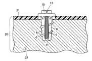
- FIG. IIIillustrates an elevation of a fastener of the invention implanted in a bone wherein the bone is illustrated partially and in section.
- FIG. IV-Ais an elevation view of another embodiment of a threaded sleeve of the invention.
- FIG. IV-Bis a top view of FIG. IV-A.
- FIG. IV-Cis a section view of FIG. IV-B taken along section line A-A.
- FIG. IV-Dis a section view of FIG. IV-B taken along section line B-B.
- FIG. IV-Eis an alternative embodiment of the sleeve of FIG. IV-A having a pointed distal end.
- FIG. IV-Fis a further alternative embodiment of the sleeve of FIG. IV-A having a bull nose distal end.
- FIG. V-Ais an elevation view of another embodiment of a threaded sleeve of the invention.
- FIG. V-Bis a top view of FIG. V-A.
- FIG. V-Cis a section view of FIG. V-A taken along section line B-B.
- FIG. VI-Ais an elevation of a wing-type sleeve of the invention.
- FIG. VI-Bis a top view of FIG. VI-A.
- FIG. VI-Cis a section view of FIG. VI-A taken along section line A-A.
- FIG. VI-Dis a section view of FIG. VI-B taken along section line B-B.
- FIG. VI-Eis an alternative embodiment of the sleeve of FIG. VI-A having sequentially activated wings.
- FIG. VII-Ais an elevation view of another embodiment of a wing-type sleeve of the invention.
- FIG. VII-Bis a top view of FIG. VII-A.
- FIG. VII-Cis a section view of FIG. VII-A taken along section line A-A.
- FIG. VII-Dis a section view of FIG. VII-B taken along section line B-B.
- FIG. VIII-Ais an elevation view of still another embodiment of a wing-type sleeve of the invention.
- FIG. VIII-Bis an elevation view of the sleeve of FIG. VIII-A which has been rotated 90° about the y-y axis.
- FIG. IX-Ais an elevation view of a pin/wing-type fastener of the invention wherein the sleeve has the same design as the sleeve of FIG. VII except for the added annular recess 81 shown in FIG. IX-B wherein FIG. IX-B is a section view of FIG. IX-A taken along section line A-A.
- FIGS. IX-C and IX-Dare section views of the sleeve of FIG. IX-A implanted in a bone with a pin set in the sleeve.
- FIG. Xis a perspective view of a sleeve of the invention installed in a plate, tibial tray or the like.
- FIG. XI-Ais an elevation view of a sleeve of the invention which is used as a plug.
- FIG. XI-Bis a top view of FIG. XI-A and FIG. XI-C is a section view taken along section line A-A.
- FIGS. XII-A-Jillustrate top views of some of the various head configurations for the screws and pins of the invention and some configurations for the flanges.
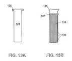
- FIGS. XIII-A and Billustrate in elevation some additional pin and screw embodiments for use with the sleeves of the invention.
- the fasteners of the inventioncan be made of various biocompatible materials and combinations of biocompatible materials.
- the sleeve and the corresponding screw or pin of a particular fastenercan be made from the same materials or different materials.
- the sleevecan be made of different materials so that one portion will be absorbed by the body more quickly than another or one portion will be absorbed and the other will not.
- Suitable materialsinclude tissue friendly metals, alloys, synthetic metals, plastics and reinforced plastics which are commonly used in surgical implants of all kinds. Such materials include materials that have sufficient strength to meet the objectives of the invention and that have been approved by the United States Food and Drug Administration (FDA) for surgical implant applications.
- FDAUnited States Food and Drug Administration
- alloys used in orthopedic metals todaythere are three main types of alloys used in orthopedic metals today, titanium alloys, cobalt alloys and stainless steel alloys.
- An exhaustive listis available on the FDA website which also provides the reference numbers and effective dates of the ASTM or ISO standards for the materials.
- Some examplesinclude unalloyed and alloyed titanium; molybdenum, chromium, cobalt, tungsten, aluminum, niobium, manganese or vanadium in various combinations as alloys or components of alloys, various stainless steels and other iron alloys; aluminum oxides, zirconium oxides, tantalum and calcium phosphates.
- high strength polymersNumerous types of high strength polymers also are employed to make implants and many of these are identified not only on the FDA website mentioned above but also on the ASTM website.
- suitable high strength polymersinclude polyetheretherketone (PEEK), epoxys, polyurethanes, polyesters, polyethylenes, vinyl chlorides, polysulfones, polytetrafluoro-ethylene (PTFE), polycarbonates, polyaryletherketone (PAEK), polyoxymethylene, nylon, carbon fiber polyester, polyetherketoneetherketoneketone (PEKEKK), silicones and the like.
- PEEKpolyetheretherketone
- PEEKpolyetheretherketone
- epoxysepoxys
- polyurethanespolyesters
- polyethylenesvinyl chlorides
- polysulfonespolytetrafluoro-ethylene
- PAEKpolycarbonates
- PAEKpolyaryletherketone
- PEKEKKpolyoxymethylene
- a small wire or other materialcan be incorporated in the main body of the base for purposes
- high strength polymer(s)is defined as any tissue-friendly non-bioabsorbable polymer, copolymer, polymer mixture, plastic or polymer alloy having sufficient strength to withstand without failure the torques and stresses that a fastener of the invention would normally be subjected to during surgery or in the body.
- Bioabsorbable materialcan also be used to make all or a portion of one or more of the component parts of the fasteners of the invention and/or the bioabsorbable material can be applied as a partial or complete coating on such component parts.
- bioabsorbable materialincludes materials which are partially or completely bioabsorbable in the body.
- Suitable bioabsorbable materialsinclude polyglycolide, poly(lactic acid), copolymers of lactic acid and glycolic acid, poly-L-lactide, poly-L-lactate; crystalline plastics such as those disclosed in U.S. Pat. No. 6,632,503 which is incorporated herein by reference; bioabsorbable polymers, copolymers or polymer alloys that are self-reinforced and contain ceramic particles or reinforcement fibers such as those described in U.S. Pat. No. 6,406,498 which is incorporated herein by reference; bioresorbable polymers and blends thereof such as described in U.S. Pat. No.
- Bioactive materialscan be admixed with the bioabsorbable materials, impregnated in the bioabsorbable materials and/or coated on the outer surface thereof and/or coated on the base or otherwise provided at the interface of the base with the bioabsorbable material.
- These materialscan include, for example, bioactive ceramic particles, bone chips, polymer chips, capsules or reinforcement fibers and they can contain, for example, antimicrobial fatty acids and related coating materials such as those described in Published U.S. Patent Application No. 2004/0153125 A1; antibiotics and antibacterial compositions; immunostimulating agents; tissue or bone growth enhancers and other active ingredients and pharmaceutical materials known in the art.
- the products of the inventioncan be made by molding, heat shrinking or coating the bioabsorbable material on a base which has been provided with attachment means such as those described in our pending patent application Ser. No. 11/025,213 filed Dec. 29, 2004 which is incorporated herein by reference. Many of the screws, pins and other devices described in our pending patent application Ser. No. 11/025,213 filed Dec. 29, 2004 can also be used in or in combination with the fasteners and/or sleeves of the present invention.
- the bioabsorbable materialwill have functional mechanical properties which are not made from the base material, the bioabsorbable material can be molded onto the base in the desired shape. Alternatively, the bioabsorbable material also can be coated, shrink wrapped or molded onto the base. If necessary, the bioabsorbable material can be machined to the desired shape and/or dimensions.
- the fasteners of the inventionare implanted in pre-drilled holes in the operating area of a patient.
- the operating areais usually in bone but it can be in cartilage and bone when a means (e.g., a washer, plate, bracket, wire or equivalent) is used to hold the cartilage down.
- the pre-drilled holeis sized to accommodate the sleeve so that the fastener will ultimately be implanted in the manner deemed most desirable by the surgeon. It will be understood that sizing the hole means the shape of the hole and any countersinking that may be desired are drilled in a manner that will cause the implanted fastener to be securely affixed in the patient during surgery. In most cases the sleeve will be implanted first.
- Threaded sleevesare implanted by screwing the sleeve into the pre-drilled hole with a wrench, screwdriver or other driver. Wing-type sleeves are installed by pushing, tapping, impacting or injecting them into place. A pin or screw is then installed in each sleeve at the appropriate time during surgery. In some surgical applications, it may be desirable to have a screw or pin partially inserted into the sleeve before the sleeve is implanted in the patient.
- the sizes of the fasteners of the inventioncan be varied over a broad range to meet their intended applications.
- the shapes, particularly the outer shapes of the sleevescan take various forms and the size, lengths, widths and number of the blades, diameters and shapes of the flange, the geometry of the longitudinal slits, etc. can be varied for particular applications within the principles of the invention set forth herein.
- the lengths of the bladescan vary, even on the same sleeve.
- the flangecan be molded or machined together with or separately from the blades.
- the flangeWhen the flange is made separately, it can be, for example, attached to the blades by heat shrinking, adhesive, tight fit, snap fit or other means known in the mechanical and fastener arts. In some cases it may be desirable for the flange to be made from a different material than the blades, for example, in applications where the flange may need to last longer than the blades or to provide a seat for a screw or pin.
- FIG. I-Aillustrates in elevation a screw/threaded-type fastener 1 of the invention before the screw 3 is inserted into the sleeve 2 .
- FIG. I-Bis an elevation of the sleeve 2 which has been rotated about axis y-y by 90° from FIG. I-A.
- FIG. I-Cis a top view of FIG. I-B and
- FIG. I-Dis a section view of FIG. I-B taken along section line A-A.
- FIG. IIillustrates the fastener 1 shown in FIG. I-A after the screw 3 has been inserted into sleeve 2 .
- the sleeve 2is in the shape of a frustum having a proximal end and a distal end and is comprised of a flange 4 at the proximal end.
- the flangeserves to provide a stop for the sleeve to allow it to rest on the cortical surface of the bone or to hold down a plate or other implant device.
- Various featurescan be designed into the flange or on the circumference of the flange for driving it into the operating area. This can include hexes, squares, slots, Phillips, spanner holes and the like, either internal or external, sized to mate with appropriate tools for implanting the sleeve into a pre-drilled hole in the operating area.
- a foot or web 5is located at the distal end.
- the foot or webis an optional feature of the invention and it is useful in applications where increased strength of the sleeve may be necessary during installation of the sleeve and prior to installation of the screw or pin.
- the footcan be comprised of a thin strip of material at the distal end and can be made of the same or different material as the sleeve.
- a web of the same or different material as the sleevecan be affixed at the distal end. The foot or web holds together the tips of the blades at the distal end of the sleeve and helps to maintain the integrity of the sleeve and avoid premature breakage when it is implanted.
- Threads 6 and anti-rotation wedges 7are disposed on the outer surface of the frustum, and the frustum generally comprises two blade sections 8 .
- the proximal endhas a larger diameter than the distal end.
- the screw 3is comprised of a shank having threads 9 disposed thereon and a head 10 .
- the longitudinal slit 14 of sleeve 2extends into an internal tapered bore 12 (see FIG. I-D).
- the borebecomes narrower as it approaches the distal end and the threads 9 , which have diameter larger than the diameter of the bore at the distal end, exert increasing pressure on the sides of the bore 12 as the screw is inserted further into the sleeve through opening 19 .
- the bore as illustrated in FIG. I-Aextends through the flange 4 at opening 19 and terminates at the foot or web 5 .
- Two longitudinal slits 14extend from the outer surface of the frustum to the bore 12 , essentially bisecting most of the outer surface of the frustum and thereby forming the blade sections 8 .
- a hexagonal slot 15is provided so that a hexagonal wrench can be used to screw the sleeve into a bone. It is understood that numerous different kinds of slots, holes or slits can be incorporated into the flange or the outer rim of the flange itself can be shaped (e.g., hexagonally) so that various types of wrenches, screwdrivers and other types of drivers can be used as tools to implant the sleeve into a pre-drilled hole in the operating area of the patient. It is also understood that the sleeve can have more than two blades and, in fact, can have several blades as may be appropriate or necessary for particular applications. The blades can be straight or tapered and can be of various shapes and sizes, even on the same sleeve.
- Threads 16mate with the threads 9 of screw 3 .
- self-tapping screwscan be used, particularly when the sleeve is made from a softer material than the screw. When self-tapping screws are used it is not necessary to have threads such as threads 16 in the sleeve.
- any sleeve of the inventioncan be designed to work with a screw or a pin to make fasteners for particular applications as will be apparent to those skilled in the art.
- the opening in the flange which receives the screw or pin accordinglycan be straight or tapered or threaded or a combination of any or all.
- the sleevecan be supplied with a mated screw, a self-tapping screw, a pin, a rod or any other device which can be affixed in the sleeve.
- the foot or web 5When screw 3 is inserted into sleeve 2 , the foot or web 5 is caused to break, as illustrated in FIG. II, by the pressure exerted by the screw on the sides of the bore 12 .
- the broken foot or web 5leaves a gap 11 and the blade sections 8 are caused to move laterally in the directions x-x, thereby expanding the sleeve.
- threads 6are also caused to move in the same lateral directions. This expansion or lateral movement secures and stabilizes the sleeve in the bone and allows the bone to grow into the space occupied by the fastener as the healing process progresses.
- FIG. IIIillustrates a screw/threaded-type fastener of the invention implanted in a bone 20 .
- the bone 20is a portion of a bone and is illustrated in section whereas the fastener is illustrated in elevation.
- the bone 20is comprised of a cortical portion 21 and a cancellous portion 22 .
- the head 10 of the screwis provided with a transverse bore 13 which extends across the diameter of the head.
- the transverse bore 13can accommodate sutures and the fastener accordingly can be used as a suture anchor or a bone anchor.
- FIG. IV-Aillustrates in elevation a threaded sleeve 32 in the shape of a frustum having a proximal end and a distal end.
- Flange 34is affixed at the proximal end and a foot or web 35 at the distal end.
- Threads 36are disposed on the outer surface of the frustum.
- the anti-rotation wedges 37are somewhat curved or angled generally in the direction of the threads and generally extend downwardly from the flange along the outer surface of the frustum.
- the anti-rotation wedgescan be straight, angled or curved as a matter of design choice that will be apparent to those skilled in the art based upon the disclosures herein.
- the frustumhas blade sections 38 . Longitudinal slits 33 extend into internal tapered bore 39 .
- slots 31are provided for a cruiform screwdriver which is used to insert the sleeve into a pre-drilled hole in the patient's bone.
- a tapered recess 30is provided in the flange 34 so that a screw or pin with a tapered head can be seated in a position flush with the top surface of the flange.
- the internal tapered bore 39is illustrated in FIG.
- IV-D and the boreis sized so that the diameter d near the distal end is less than the diameter of the screw or pin which is inserted into the proximal end of the sleeve through opening 29 . Accordingly, when the screw or pin is inserted, the foot or web 35 is caused to break and the blades 38 are pushed laterally outward thereby affixing the sleeve more securely in the bone.
- FIG. IV-Eillustrates an alternative embodiment of the sleeve of FIG. IV-A having a pointed distal end 23 and a slit 24 .
- the slitpermits the blades to move apart laterally when a screw or pin is installed in the sleeve.
- FIG. IV-Fillustrates still another embodiment with a bull nose distal end 25 and a slit 26 .
- the pointed distal end and the bull nose distal end, each with a slit as illustrated (and the slit can be a very thin slit such as a hairline slit)can be provided as an element of the design of any of the various sleeves of the invention. Either design is particularly useful in applications where possible breakage of the bone may be caused by installation of the sleeve.
- FIG. V-Aillustrates in elevation a threaded sleeve 2 having threads 46 positioned near the flange 44 so that they primarily engage the outside cortical shell of the bone.
- the flange 44is also tapered so that its upper surface can be flush with the surface of the bone or a plate when it mates with a pre-drilled countersink at the outer edge of the pre-drilled hole in the bone or plate. In most cases countersinks are made in plates rather than in bone but in some operations, for example in the knee, a countersink in the bone may be desirable.
- the sleevehas three blades 48 and an internal tapered bore 49 .
- the longitudinal slits 43extend all the way to a web 45 at the distal end.
- FIGS. VI-A, B, C and Dillustrate a wing-type sleeve 52 having wings 56 longitudinally disposed thereon.
- An elevation of sleeve 52is illustrated in FIG. VI-A with a flange 54 at the proximal end and a foot or web 55 at the distal end.
- the screw or pincan be sized so that it does not reach the foot or web 55 when fully inserted into the sleeve, in which case the foot or web will not break but will remain closed.
- a longer screw or pincan be used which will break the foot or web 55 when fully inserted thereby also causing blades 58 to be actuated (i.e., pushed outwardly in a generally lateral direction).
- FIG. VI-Eis an alternative embodiment of sleeve 52 , illustrated in the same section view as shown in FIG. VI-C.
- wing 56 ais actuated before wing 56 is actuated because the screw or pin will reach wing 56 a before it reaches wing 56 .
- This sequential actuationis particularly useful to prevent rotation of the sleeve when a screw is inserted into opening 27 and when a lot of pressure is being exerted on the screw which could otherwise cause rotation of the sleeve.
- FIGS. VII-A, B, C and DAnother embodiment of a wing-type sleeve 62 is illustrated in FIGS. VII-A, B, C and D.
- FIG. VII-Aillustrates the sleeve in an elevation view and FIG. VII-B is a top view of FIG. VII-A.
- FIG. VII-Cis a section view taken along section line A-A and
- FIG. VII-Dis a section view taken along section line B-B.
- the sleevehas three blades 68 each having a wing 66 affixed and longitudinally disposed thereon. Longitudinal slits 63 open to an internal tapered bore 69 .
- the boreextends through the flange 64 at opening 26 and a tapered portion 60 allows a screw or pin to be installed so that the top surface of the screw or pin is flush with the top surface of the sleeve.
- the top surface of the sleevecan also be made flush with the top surface of a bone or plate or other implant device in which it is installed by preparing the bone or plate or other implant device with a countersink which is sized to accommodate the flange 64 .
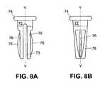
- FIGS. VIII-A and VIII-Billustrate still another embodiment of a wing-type sleeve of the invention. Both figures are elevation views with FIG. VIII-B illustrating the sleeve of FIG. VIII-A after it has been rotated 90° about the y-y axis.
- the sleeve 72is provided with a flange 74 , two blades 78 , two wings 76 and a longitudinal slit 73 . It should be noted that this sleeve does not have a foot or a web. And when such sleeves are installed in a pre-drilled hole, the hole may be sized to cause the blades to move toward one another at the distal end of the sleeve. This results in more deflection of the blades into the bone and a tighter fit when a screw or pin is inserted into the sleeve.
- FIGS. IX-A and IX-Billustrate a sleeve of the type shown in FIG. VII except that an annular recess 81 is provided to receive an optional annular ring 71 disposed in an annular groove on the shank 77 of pin 70 .
- an annular recess 81is provided to receive an optional annular ring 71 disposed in an annular groove on the shank 77 of pin 70 .
- the annular ring 71is snap fit into the annular recess 81 thereby holding the pin firmly in place.
- Head 75 of the pin 70is seated in tapered portion 80 of the flange 84 when the pin is installed in the sleeve.
- Longitudinal slits 83extend into the tapered bore 89 .
- the top surface of the pinis flush with the top surface of the sleeve and a countersink recess can be made in the cortical portion 91 of the bone so that the entire fastener is flush with the top surface of the bone.
- the installation of the pin 70 into the sleeve 82causes the blades 88 and the wings 86 to move laterally into the cancellous portion 90 of the bone thereby firmly affixing the fastener in the bone.
- the head of the pinis flush with the top surface of the flange and the cortical portion. Of course, other head designs which are not flush can be used.
- FIG. IX-Dillustrates a variation of FIG. IX-C wherein a longer pin 77 is used to affix a plate 94 to a bone.
- the cortical portion of the bone 93is drilled to accommodate the flange 84 and the optional annular ring 71 is located on the pin 77 at a certain measured distance from head 79 so that the top surface of head 79 will be flush with the top surface of the plate 94 when the ring 71 is snap fit into sleeve 82 at annular recess 81 .
- the sleeveis affixed in the bone in the same manner as described in respect of FIG. IX-C wherein the blades 88 and the wings 86 are laterally extended into the cancellous portion 92 of the bone.
- FIG. Xis a perspective view of a sleeve 102 installed in a countersink 103 in a plate or tibial tray 104 . Comparing FIG. IX-D, this is a different way of using the fastener of the invention in combination with a plate because in this case the sleeve is countersunk in the plate and affixed in the bone. In FIG. IX-D the sleeve is fixed only in the bone and the pin secures the plate.
- FIGS. XI-A, B and Cillustrate sleeve 112 having a flange 114 at the proximal end, a foot or web 115 at the distal end, threads 116 and anti-rotation wedges 117 . Opening 120 provides access to cavity 119 .
- Sleeve 112can be used as a plug and the cavity can optionally be filled with any form or combination of bone, coral, PEEK chips, allograph, ceramics, bone wax, medications such as antibiotics, bioactive materials, antibacterial compositions, immunostimulating agents, tissue or bone growth enhancers and other active and inactive ingredients and pharmaceutical materials known in the art.
- a suitable screw, pin or plugis used to close opening 120 after the sleeve is implanted and the cavity has been optionally filled with a foregoing material.
- This sleevecan have any desired shape or size as with the other sleeves of the invention.
- the sleeveoptionally can be made from a bioabsorbable material which will gradually dissolve and cause the contents to be released over time.
- the other sleeves of the inventionwhich have longitudinal slits and blades can be used in the same manner as sleeve 112 wherein the slits will allow for more rapid release of any active materials that may be filled into the internal bore. The slits also permit faster bone growth.
- a sleeve of the inventionWhen a sleeve of the invention is used as a plug as described herein it is normally used to fill a hole created by a previous procedure such as the removal of implants of various kinds such as screws, halos and the like.
- the plugscan stop bleeding, prevent infection, enhance bone growth and perform various other beneficial functions.
- FIG. XII-A-Jillustrates top views of some of the head design types for screws and pins that can be used in the invention and some of the design types for the flanges. These illustrations are not intended to include all of the possible designs and others can be used as will be apparent to those skilled in the art. All of the illustrated designs can be used for flanges or pin heads and FIGS. XII-A-I can be used for screws. It will be understood by those having skill in the art based upon the disclosures herein that that when any of the designs are used for a flange they will also include an opening for a screw or a pin. An example of such an opening being the opening 19 in a flange having an internal hex as illustrated in FIG. IC. FIG.
- FIG. XII-Aillustrates a standard slot.
- FIG. XII-Bcan be a Philips or a cruiform.
- FIG. XII-Cis a spanner and D is a torq.
- FIG. XII-Eis an Allen, F is a square head and G is an external hex.
- FIG. XII-His a new design, I is an internal hex and J is a pin head or flange.
- FIG. XIII-Aillustrates in elevation a pin 123 with head 126
- FIG. XIII-Billustrates in elevation a screw 133 with a head 135 , a retaining ring 137 disposed in an annular ring on the shank and threads 139 disposed on said shank.
- Theseare intended to show some alternative embodiments to those screws and pins already illustrated. Variations thereon will be apparent to those skilled in the art.
- Either the pin 123 or the screw 133could be used, for example, with the sleeve of FIGS. IX-A and B.
- the retaining ring 137 illustrated on the screw 133prevents rotation and loosening of the screw after it is installed in the sleeve, but the retaining ring does not prevent the intentional removal of the screw by a surgeon.
Landscapes
- Health & Medical Sciences (AREA)
- Orthopedic Medicine & Surgery (AREA)
- Surgery (AREA)
- Life Sciences & Earth Sciences (AREA)
- Heart & Thoracic Surgery (AREA)
- Nuclear Medicine, Radiotherapy & Molecular Imaging (AREA)
- Engineering & Computer Science (AREA)
- Biomedical Technology (AREA)
- Neurology (AREA)
- Medical Informatics (AREA)
- Molecular Biology (AREA)
- Animal Behavior & Ethology (AREA)
- General Health & Medical Sciences (AREA)
- Public Health (AREA)
- Veterinary Medicine (AREA)
- Surgical Instruments (AREA)
- Prostheses (AREA)
Abstract
Description
Claims (28)
Priority Applications (4)
| Application Number | Priority Date | Filing Date | Title |
|---|---|---|---|
| US11/107,610US8128670B2 (en) | 2005-04-15 | 2005-04-15 | Surgical expansion fasteners |
| AU2006237638AAU2006237638A1 (en) | 2005-04-15 | 2006-03-01 | Surgical expansion fasteners |
| PCT/US2006/007271WO2006112955A2 (en) | 2005-04-15 | 2006-03-01 | Surgical expansion fasteners |
| EP06736565AEP1868516A4 (en) | 2005-04-15 | 2006-03-01 | Surgical expansion fasteners |
Applications Claiming Priority (1)
| Application Number | Priority Date | Filing Date | Title |
|---|---|---|---|
| US11/107,610US8128670B2 (en) | 2005-04-15 | 2005-04-15 | Surgical expansion fasteners |
Publications (2)
| Publication Number | Publication Date |
|---|---|
| US20060235410A1 US20060235410A1 (en) | 2006-10-19 |
| US8128670B2true US8128670B2 (en) | 2012-03-06 |
Family
ID=37109515
Family Applications (1)
| Application Number | Title | Priority Date | Filing Date |
|---|---|---|---|
| US11/107,610Expired - Fee RelatedUS8128670B2 (en) | 2005-04-15 | 2005-04-15 | Surgical expansion fasteners |
Country Status (4)
| Country | Link |
|---|---|
| US (1) | US8128670B2 (en) |
| EP (1) | EP1868516A4 (en) |
| AU (1) | AU2006237638A1 (en) |
| WO (1) | WO2006112955A2 (en) |
Cited By (8)
| Publication number | Priority date | Publication date | Assignee | Title |
|---|---|---|---|---|
| US20060129148A1 (en)* | 2004-10-01 | 2006-06-15 | Simmons Edward D | Screw sleeve made of polyetheretherketone (PEEK) for augmentation of bone screw insertion in osteoporotic or revision lumbar spine instrumentation |
| US20110144766A1 (en)* | 2008-06-19 | 2011-06-16 | Shreedhar Kale | Allograft Bone Plugs, Systems and Techniques |
| US20120064487A1 (en)* | 2007-02-01 | 2012-03-15 | Sargon Lazarof | Dental securing mechanism with varying thread size |
| US20120259372A1 (en)* | 2007-01-19 | 2012-10-11 | Pbj, Llc | Orthopedic screw insert |
| US20210378721A1 (en)* | 2011-11-01 | 2021-12-09 | Nuvasive, Inc. | Surgical fixation system and related methods |
| US11259845B2 (en)* | 2017-03-30 | 2022-03-01 | K2M, Inc. | Bone anchor apparatus and method of use thereof |
| AT524170A1 (en)* | 2020-09-07 | 2022-03-15 | V I E Systems Gmbh | Plate for plating, fastener and set |
| US20230363887A1 (en)* | 2013-03-15 | 2023-11-16 | Conmed Corporation | System and method for securing tissue to bone |
Families Citing this family (74)
| Publication number | Priority date | Publication date | Assignee | Title |
|---|---|---|---|---|
| US8105367B2 (en) | 2003-09-29 | 2012-01-31 | Smith & Nephew, Inc. | Bone plate and bone plate assemblies including polyaxial fasteners |
| US8900236B2 (en)* | 2004-04-20 | 2014-12-02 | James Chappuis | Internal pedicle insulator implants assemblies and methods of use |
| US20060217717A1 (en)* | 2005-03-24 | 2006-09-28 | Dale Whipple | Methods and devices for stabilizing a bone anchor |
| US8382807B2 (en) | 2005-07-25 | 2013-02-26 | Smith & Nephew, Inc. | Systems and methods for using polyaxial plates |
| CA2616798C (en) | 2005-07-25 | 2014-01-28 | Smith & Nephew, Inc. | Systems and methods for using polyaxial plates |
| AU2006282828B2 (en) | 2005-08-23 | 2013-01-31 | Smith & Nephew, Inc | Telemetric orthopaedic implant |
| US8998923B2 (en) | 2005-08-31 | 2015-04-07 | Spinealign Medical, Inc. | Threaded bone filling material plunger |
| US8043347B2 (en)* | 2005-12-29 | 2011-10-25 | Industrial Technology Research Institute | Device and method for fixing soft tissue |
| US9849216B2 (en) | 2006-03-03 | 2017-12-26 | Smith & Nephew, Inc. | Systems and methods for delivering a medicament |
| US7862573B2 (en)* | 2006-04-21 | 2011-01-04 | Darois Roger E | Method and apparatus for surgical fastening |
| WO2008010948A2 (en) | 2006-07-18 | 2008-01-24 | Davol Inc. | Method and apparatus for surgical fastening |
| TWM306498U (en)* | 2006-08-10 | 2007-02-21 | Shih-Tseng Lee | Securing member, expansion anchroing screw set |
| US20080294204A1 (en)* | 2007-03-07 | 2008-11-27 | Spineworks Medical, Inc. | Systems, methods, and devices for soft tissue attachment to bone |
| US8267978B2 (en)* | 2006-09-14 | 2012-09-18 | Warsaw Orthopedic, Inc. | Hybrid bone fixation apparatus |
| US20080177330A1 (en)* | 2006-10-24 | 2008-07-24 | Ralph James D | Self-locking screws for medical implants |
| WO2008060849A2 (en)* | 2006-11-15 | 2008-05-22 | Carl Hasselman | Tissue fastener, and tissue fastener system and method employing the same |
| WO2008109870A1 (en)* | 2007-03-07 | 2008-09-12 | Spinealign Medical, Inc. | Transdiscal interbody fusion device and method |
| US20080234682A1 (en)* | 2007-03-16 | 2008-09-25 | Park Maxwell C | Augmentation device for osteoporotic bone |
| FR2915082B1 (en)* | 2007-04-19 | 2010-08-13 | Ceria Conception Etudes Realis | OSTEOSYNTHESIS SYSTEM FOR CONNECTING AT LEAST TWO VERTEBRATES. |
| WO2008137192A1 (en)* | 2007-05-08 | 2008-11-13 | Spinealign Medical, Inc. | Systems, devices and methods for stabilizing bone |
| US8696716B2 (en)* | 2007-08-02 | 2014-04-15 | Proactive Orthopedics, Llc | Fixation and alignment device and method used in orthopaedic surgery |
| US8882816B2 (en) | 2007-08-02 | 2014-11-11 | Proactive Orthopedics, Llc | Fixation and alignment device and method used in orthopaedic surgery |
| GB0804998D0 (en) | 2008-03-18 | 2008-04-16 | Depuy Ireland Ltd | A cup component of an orthopaedic joint prosthesis |
| EP2306913A4 (en)* | 2008-03-28 | 2014-06-04 | Warsaw Orthopedic Inc | Bone anchors for orthopedic applications |
| CA2722607A1 (en)* | 2008-04-28 | 2009-11-05 | Stephen J. Lewis | Anchor for use with orthopedic screw |
| US9351778B2 (en)* | 2008-06-20 | 2016-05-31 | Yale University | Porous expansion bolt |
| US9408649B2 (en) | 2008-09-11 | 2016-08-09 | Innovasis, Inc. | Radiolucent screw with radiopaque marker |
| BRPI0920250A2 (en) | 2008-10-15 | 2016-11-22 | Smith & Nephew Inc | composite internal fasteners |
| EP2745789B1 (en) | 2008-10-30 | 2017-04-19 | Depuy Spine Inc. | Systems for delivering bone cement to a bone anchor |
| ES2350021B1 (en)* | 2008-12-10 | 2011-08-05 | Tequir, S.L. | EXPANSIBLE COVER FOR PEDICULAR SCREWS. |
| US9848923B2 (en)* | 2009-07-28 | 2017-12-26 | DePuy Synthes Products, Inc. | Locking system for orthopedic implants |
| US9433439B2 (en) | 2009-09-10 | 2016-09-06 | Innovasis, Inc. | Radiolucent stabilizing rod with radiopaque marker |
| DE102010039756A1 (en)* | 2009-09-28 | 2011-03-31 | Hilti Aktiengesellschaft | Method for producing a fastening device |
| US9078701B2 (en)* | 2009-11-09 | 2015-07-14 | Centinel Spine, Inc. | System and method for stabilizing a posterior fusion over motion segments |
| US8801712B2 (en)* | 2010-03-08 | 2014-08-12 | Innovasis, Inc. | Radiolucent bone plate with radiopaque marker |
| WO2012097326A2 (en)* | 2011-01-14 | 2012-07-19 | Alphatec Spine, Inc. | Expandable facet screw |
| CA2826941C (en)* | 2011-02-14 | 2019-09-10 | Glenn R. Buttermann | Orthopaedic device |
| US9687278B2 (en) | 2011-03-21 | 2017-06-27 | Ronald Childs | Sleeve for bone fixation device |
| EP2688605A4 (en)* | 2011-03-24 | 2014-09-10 | Bard Inc C R | Fixation and protection of an implanted medical device |
| US9161794B2 (en) | 2011-04-14 | 2015-10-20 | Globus Medical, Inc. | Expanding spinal anchor |
| US20140222088A1 (en)* | 2011-05-08 | 2014-08-07 | Spinal Ventures, Llc | Implant and Fastener Fixation Devices and Delivery Instrumentation |
| AU2012271441B2 (en) | 2011-06-15 | 2017-02-02 | Smith & Nephew, Inc. | Variable angle locking implant |
| US9155580B2 (en) | 2011-08-25 | 2015-10-13 | Medos International Sarl | Multi-threaded cannulated bone anchors |
| US9101399B2 (en) | 2011-12-29 | 2015-08-11 | Proactive Orthopedics, Llc | Anchoring systems and methods for surgery |
| CN104271057A (en)* | 2012-03-12 | 2015-01-07 | 维克辛姆公司 | Universal anchor for bone fixation |
| KR101713787B1 (en)* | 2012-05-10 | 2017-03-08 | 호메이욘 에이치. 자데흐 | Dental devices for extraction site reconstruction |
| US20140058461A1 (en)* | 2012-08-27 | 2014-02-27 | Michael Black | Fenestrated Bone Screw |
| US20140067069A1 (en) | 2012-08-30 | 2014-03-06 | Interventional Spine, Inc. | Artificial disc |
| US9198657B2 (en)* | 2012-09-13 | 2015-12-01 | Basil Anthony Kocur | Anchor unit implant |
| US9681905B2 (en) | 2012-10-02 | 2017-06-20 | Alphatec Spine, Inc. | Expandable screw and methods of use |
| FR2996115B1 (en) | 2012-10-03 | 2015-05-29 | Biotech Ortho | SUPPORT OF ORTHOPEDIC SCREW. |
| CA2927433C (en)* | 2012-10-15 | 2020-03-10 | Dynamic Spine, Llc | Orthopaedic device with orthopaedic plate and rotatable tissue protector |
| US20140188179A1 (en)* | 2012-12-27 | 2014-07-03 | Wright Medical Technology, Inc. | Percutaneous flaring hammertoe fixation implant and instrument |
| US20160022386A1 (en)* | 2013-03-12 | 2016-01-28 | Azenium Ip Limited | A dental implant |
| ITFI20130114A1 (en)* | 2013-05-20 | 2014-11-21 | Claudio Giuntini | BONE FIXING ELEMENT |
| KR101599603B1 (en) | 2013-08-26 | 2016-03-03 | 경북대학교 산학협력단 | Medical inserting apparatus |
| ES2804126T3 (en)* | 2014-02-24 | 2021-02-03 | Univ Curtin Tech | Bra |
| KR101639887B1 (en) | 2014-11-11 | 2016-07-14 | 경북대학교 산학협력단 | A system for fixing cervical vertebrae and a driver used for an appratus for fixing cervical vertebrae |
| KR101608949B1 (en) | 2014-11-19 | 2016-04-04 | 경북대학교 산학협력단 | A system for fixing cervical vertebrae, an appratus for fixing cervical vertebrae and a driver used for an appratus for fixing cervical vertebrae |
| US11234747B2 (en) | 2015-02-25 | 2022-02-01 | National University Corporation Tokyo Medical And Dental University | Medical device, device structures for dentistry, for head and neck surgery and for orthopedic surgery, and method for bonding medical device to bone |
| KR101670768B1 (en) | 2015-07-16 | 2016-10-31 | 경북대학교 산학협력단 | Screw anchor assembly |
| GB2557840B (en) | 2015-09-18 | 2021-07-21 | Smith & Nephew Inc | Bone plate |
| US10874445B2 (en) | 2015-10-13 | 2020-12-29 | Kyungpook National University Industry-Academic Cooperation Foundation | Screw fixing apparatus |
| KR101712610B1 (en) | 2015-12-29 | 2017-03-06 | 경북대학교 산학협력단 | A rod connecter |
| KR101791004B1 (en) | 2016-06-08 | 2017-10-27 | 경북대학교 산학협력단 | Screw anchor assembly and a method for using the same to pedicle screw instrumentation |
| DE102016117490A1 (en)* | 2016-09-16 | 2018-03-22 | Christoph U. Schulz | Orthopedic bone anchor |
| US11284874B2 (en)* | 2016-10-11 | 2022-03-29 | Peter Scott Borden | Snap lock |
| WO2018183088A1 (en)* | 2017-03-30 | 2018-10-04 | K2M, Inc. | Surgical fixation assembly and methods of use |
| US10172656B1 (en) | 2017-09-15 | 2019-01-08 | Alphatec Spine, Inc. | Surgical screw |
| CN108245771A (en)* | 2018-02-02 | 2018-07-06 | 南方医科大学南方医院 | Orthopaedics implantable drug delivery system |
| CN109223156B (en)* | 2018-10-20 | 2021-10-12 | 任敏 | External fixation spicule structure |
| CN109223147B (en)* | 2018-10-22 | 2021-09-10 | 桂林医学院附属医院 | Bone needle easy to pull out |
| TR2021015278A2 (en)* | 2021-09-30 | 2021-10-21 | Hakan Cici | ORTHOPEDIC EXPANDABLE BLADE SCREW ANCHOR SYSTEM |
| KR102752952B1 (en)* | 2022-08-08 | 2025-01-14 | 경북대학교 산학협력단 | Artificial bone for micro-invasiveness and insertion method using the same |
Citations (65)
| Publication number | Priority date | Publication date | Assignee | Title |
|---|---|---|---|---|
| US3385156A (en) | 1966-03-30 | 1968-05-28 | Dan Polos Ind Inc | Self-drilling anchor bolt assembly |
| US3487746A (en) | 1968-04-01 | 1970-01-06 | Bertram H Kapnek | Screw anchor |
| US3651934A (en) | 1969-07-16 | 1972-03-28 | Container Corp | Structure for nestably packing chairs for shipment |
| US3888156A (en) | 1974-03-29 | 1975-06-10 | Raoul Fima | Anchor bolt construction |
| US4143581A (en) | 1977-06-06 | 1979-03-13 | Dry Dock Industries, Inc. | Anchoring retainer for threaded fasteners |
| US4152968A (en) | 1977-11-12 | 1979-05-08 | Guy Lassine | Fastening plug |
| US4197781A (en) | 1978-04-18 | 1980-04-15 | Giannuzzi Louis | Screw anchor |
| US4233881A (en) | 1978-05-05 | 1980-11-18 | Carrier Vernon J | Wall fastener structure |
| US4236512A (en) | 1978-02-12 | 1980-12-02 | Jacob Aginsky | Connector for fractured bones |
| US4248458A (en) | 1979-05-29 | 1981-02-03 | Brody Samuel M | Random race winner selector device |
| US4275717A (en) | 1979-07-27 | 1981-06-30 | Zimmer Usa, Inc. | Intramedullary fixation device for fractured tubular bones |
| US4285225A (en) | 1979-12-07 | 1981-08-25 | Snell John H | Tool for installation of toggle-screw anchors |
| US4307598A (en) | 1980-05-12 | 1981-12-29 | Andrich Michael S | Tool for collapsing hollow-wall anchors |
| US4388031A (en) | 1980-10-03 | 1983-06-14 | Rodgers Earl T | Blind fastener device |
| US4415299A (en) | 1977-06-06 | 1983-11-15 | Dry Dock Industries, Inc. | Anchoring retainer for threaded fasteners |
| US4453539A (en) | 1982-03-01 | 1984-06-12 | The University Of Toledo | Expandable intramedullary nail for the fixation of bone fractures |
| US4590930A (en) | 1983-06-22 | 1986-05-27 | Lloyd A. Kurth | Fixation device and process for an intramedullary nail |
| US4632101A (en) | 1985-01-31 | 1986-12-30 | Yosef Freedland | Orthopedic fastener |
| US4657456A (en) | 1983-06-03 | 1987-04-14 | Usm Corporation | Blind screw anchor |
| US4704057A (en) | 1976-09-15 | 1987-11-03 | Mechanical Plastics Corp. | Fastening element |
| US4716893A (en)* | 1985-03-11 | 1988-01-05 | Artur Fischer | Bone fastener |
| US4721103A (en) | 1985-01-31 | 1988-01-26 | Yosef Freedland | Orthopedic device |
| US4752170A (en) | 1986-09-04 | 1988-06-21 | Mechanical Plastics Corp. | Fastening device with nesting anchoring elements |
| US4764065A (en) | 1987-05-06 | 1988-08-16 | Johnson Carl D | Wall anchor |
| US4828439A (en) | 1987-05-15 | 1989-05-09 | Giannuzzi Louis | Screw anchor |
| US4862883A (en) | 1988-04-21 | 1989-09-05 | Yosef Freeland | Interlocking intramedullary nail |
| US5057103A (en) | 1990-05-01 | 1991-10-15 | Davis Emsley A | Compressive intramedullary nail |
| US5098433A (en) | 1989-04-12 | 1992-03-24 | Yosef Freedland | Winged compression bolt orthopedic fastener |
| US5203864A (en) | 1991-04-05 | 1993-04-20 | Phillips Edward H | Surgical fastener system |
| US5236438A (en) | 1992-09-10 | 1993-08-17 | Wilk Peter J | Method and assembly for repairing liver laceration |
| US5244324A (en) | 1992-08-18 | 1993-09-14 | Dry Dock Industries, Inc. | Anchoring retainer for threaded fastener |
| US5268001A (en)* | 1990-09-25 | 1993-12-07 | Innovasive Devices, Inc. | Bone fastener |
| US5439381A (en) | 1992-09-28 | 1995-08-08 | Cohen; Howard | Dental implant apparatus and method |
| US5462552A (en) | 1992-11-20 | 1995-10-31 | Kiester; P. Douglas | Bone cement removal and apparatus |
| US5470230A (en) | 1994-09-30 | 1995-11-28 | Daftary; Fereidoun | Anatomical dental implant with expandable root |
| US5509765A (en) | 1994-08-12 | 1996-04-23 | Albin; Stephen D. | Removable Molly bolt |
| US5601558A (en) | 1993-02-17 | 1997-02-11 | Smith & Nephew Endoscopy, Inc. | Soft tissue anchors and systems for implantation |
| US5690454A (en) | 1992-11-23 | 1997-11-25 | Dry Dock Industries, Inc. | Anchoring retainer for threaded fasteners |
| US5720753A (en)* | 1991-03-22 | 1998-02-24 | United States Surgical Corporation | Orthopedic fastener |
| US5849004A (en) | 1996-07-17 | 1998-12-15 | Bramlet; Dale G. | Surgical anchor |
| US5911721A (en) | 1990-09-25 | 1999-06-15 | Innovasive Devices, Inc. | Bone fastener |
| US5935169A (en)* | 1997-02-13 | 1999-08-10 | Chan; Kwan-Ho | Bone cement plug for deployment in a bone canal |
| US5957953A (en)* | 1996-02-16 | 1999-09-28 | Smith & Nephew, Inc. | Expandable suture anchor |
| US5976139A (en) | 1996-07-17 | 1999-11-02 | Bramlet; Dale G. | Surgical fastener assembly |
| US5980524A (en) | 1997-06-02 | 1999-11-09 | Innovasive Devices, Inc. | Device for repairing a meniscal tear in a knee and method |
| US5980559A (en)* | 1996-08-19 | 1999-11-09 | Bonutti; Peter M. | Suture anchor |
| US6062785A (en) | 1998-08-17 | 2000-05-16 | Mcdermott; Troy | Anchoring fastener |
| US6077265A (en) | 1995-04-21 | 2000-06-20 | Werding; Gerd | Nail for fixing the position and shape of broken long bones |
| US6146384A (en) | 1995-10-13 | 2000-11-14 | Sdgi Holdings, Inc. | Orthopedic fixation device and method of implantation |
| US6241732B1 (en)* | 1998-11-03 | 2001-06-05 | David W. Overaker | Biocompatible absorbable rivets and pins for use in surgical procedures |
| US20010005475A1 (en)* | 1998-06-04 | 2001-06-28 | Robert Frigg | Blind rivet with fastener |
| US6270304B1 (en) | 1993-03-23 | 2001-08-07 | Yosef Freedland | Tension adjusting device |
| US6287310B1 (en) | 1995-09-29 | 2001-09-11 | Biomedical Enterprises, Inc. | Fasteners having coordinated self-seeking conforming members and uses thereof |
| US6290701B1 (en) | 2000-01-11 | 2001-09-18 | Albert Enayati | Bioabsorbable rivet bone fastener |
| US20020161369A1 (en) | 2001-04-25 | 2002-10-31 | Bramlet Dale G. | Intramedullary nail |
| US6551282B1 (en) | 1998-02-23 | 2003-04-22 | Tyco Healthcare Group Lp | Universal seal for use with endoscopic cannula |
| US6583232B1 (en) | 1998-07-07 | 2003-06-24 | Smith & Nephew Plc | Blend of bioresorbable polymers |
| US6613053B1 (en) | 2001-10-25 | 2003-09-02 | Corin Limited | Surgical implant |
| US20040092937A1 (en) | 2000-10-23 | 2004-05-13 | Criscuolo Christopher J. | Absorbable fastener and applying apparatus |
| US6755831B2 (en) | 2001-11-30 | 2004-06-29 | Regents Of The University Of Minnesota | Wrist surgery devices and techniques |
| US20040153125A1 (en) | 2002-12-13 | 2004-08-05 | Mark Roby | Antimicrobial fatty acid containing suture coating |
| US20040208721A1 (en) | 2003-04-17 | 2004-10-21 | Rainer Kuenzel | Fastener adapted for use with a structural member |
| US6942666B2 (en) | 2002-03-29 | 2005-09-13 | Ethicon, Inc. | Expandable cable anchor |
| US20060074421A1 (en) | 2003-05-08 | 2006-04-06 | Bickley Barry T | Fixation augmentation device and related techniques |
| US20060206208A1 (en) | 1999-05-05 | 2006-09-14 | Sdgi Holdings, Inc. | Push-in interbody spinal fusion implant with multi-lock for locking opposed screws and method for use thereof |
Family Cites Families (3)
| Publication number | Priority date | Publication date | Assignee | Title |
|---|---|---|---|---|
| US6406498B1 (en) | 1998-09-04 | 2002-06-18 | Bionx Implants Oy | Bioactive, bioabsorbable surgical composite material |
| JP3418350B2 (en) | 1998-09-14 | 2003-06-23 | タキロン株式会社 | Biodegradable and absorbable implant material and its shape adjusting method |
| US20060142772A1 (en) | 2004-12-29 | 2006-06-29 | Ralph James D | Surgical fasteners and related implant devices having bioabsorbable components |
- 2005
- 2005-04-15USUS11/107,610patent/US8128670B2/ennot_activeExpired - Fee Related
- 2006
- 2006-03-01EPEP06736565Apatent/EP1868516A4/ennot_activeWithdrawn
- 2006-03-01WOPCT/US2006/007271patent/WO2006112955A2/enactiveApplication Filing
- 2006-03-01AUAU2006237638Apatent/AU2006237638A1/ennot_activeAbandoned
Patent Citations (71)
| Publication number | Priority date | Publication date | Assignee | Title |
|---|---|---|---|---|
| US3385156A (en) | 1966-03-30 | 1968-05-28 | Dan Polos Ind Inc | Self-drilling anchor bolt assembly |
| US3487746A (en) | 1968-04-01 | 1970-01-06 | Bertram H Kapnek | Screw anchor |
| US3651934A (en) | 1969-07-16 | 1972-03-28 | Container Corp | Structure for nestably packing chairs for shipment |
| US3888156A (en) | 1974-03-29 | 1975-06-10 | Raoul Fima | Anchor bolt construction |
| US4704057A (en) | 1976-09-15 | 1987-11-03 | Mechanical Plastics Corp. | Fastening element |
| US4415299A (en) | 1977-06-06 | 1983-11-15 | Dry Dock Industries, Inc. | Anchoring retainer for threaded fasteners |
| US4143581A (en) | 1977-06-06 | 1979-03-13 | Dry Dock Industries, Inc. | Anchoring retainer for threaded fasteners |
| US4152968A (en) | 1977-11-12 | 1979-05-08 | Guy Lassine | Fastening plug |
| US4236512A (en) | 1978-02-12 | 1980-12-02 | Jacob Aginsky | Connector for fractured bones |
| US4197781A (en) | 1978-04-18 | 1980-04-15 | Giannuzzi Louis | Screw anchor |
| US4233881A (en) | 1978-05-05 | 1980-11-18 | Carrier Vernon J | Wall fastener structure |
| US4248458A (en) | 1979-05-29 | 1981-02-03 | Brody Samuel M | Random race winner selector device |
| US4275717A (en) | 1979-07-27 | 1981-06-30 | Zimmer Usa, Inc. | Intramedullary fixation device for fractured tubular bones |
| US4285225A (en) | 1979-12-07 | 1981-08-25 | Snell John H | Tool for installation of toggle-screw anchors |
| US4307598A (en) | 1980-05-12 | 1981-12-29 | Andrich Michael S | Tool for collapsing hollow-wall anchors |
| US4388031A (en) | 1980-10-03 | 1983-06-14 | Rodgers Earl T | Blind fastener device |
| US4453539A (en) | 1982-03-01 | 1984-06-12 | The University Of Toledo | Expandable intramedullary nail for the fixation of bone fractures |
| US4657456A (en) | 1983-06-03 | 1987-04-14 | Usm Corporation | Blind screw anchor |
| US4590930A (en) | 1983-06-22 | 1986-05-27 | Lloyd A. Kurth | Fixation device and process for an intramedullary nail |
| US4632101A (en) | 1985-01-31 | 1986-12-30 | Yosef Freedland | Orthopedic fastener |
| US4721103A (en) | 1985-01-31 | 1988-01-26 | Yosef Freedland | Orthopedic device |
| US4716893A (en)* | 1985-03-11 | 1988-01-05 | Artur Fischer | Bone fastener |
| US4752170A (en) | 1986-09-04 | 1988-06-21 | Mechanical Plastics Corp. | Fastening device with nesting anchoring elements |
| US4764065A (en) | 1987-05-06 | 1988-08-16 | Johnson Carl D | Wall anchor |
| US4828439A (en) | 1987-05-15 | 1989-05-09 | Giannuzzi Louis | Screw anchor |
| US4862883A (en) | 1988-04-21 | 1989-09-05 | Yosef Freeland | Interlocking intramedullary nail |
| US5098433A (en) | 1989-04-12 | 1992-03-24 | Yosef Freedland | Winged compression bolt orthopedic fastener |
| US5057103A (en) | 1990-05-01 | 1991-10-15 | Davis Emsley A | Compressive intramedullary nail |
| US5968044A (en) | 1990-09-25 | 1999-10-19 | Innovasive Devices, Inc. | Bone fastener |
| US5911721A (en) | 1990-09-25 | 1999-06-15 | Innovasive Devices, Inc. | Bone fastener |
| US5268001A (en)* | 1990-09-25 | 1993-12-07 | Innovasive Devices, Inc. | Bone fastener |
| US5720753A (en)* | 1991-03-22 | 1998-02-24 | United States Surgical Corporation | Orthopedic fastener |
| US5203864A (en) | 1991-04-05 | 1993-04-20 | Phillips Edward H | Surgical fastener system |
| US5244324A (en) | 1992-08-18 | 1993-09-14 | Dry Dock Industries, Inc. | Anchoring retainer for threaded fastener |
| US5236438A (en) | 1992-09-10 | 1993-08-17 | Wilk Peter J | Method and assembly for repairing liver laceration |
| US5439381A (en) | 1992-09-28 | 1995-08-08 | Cohen; Howard | Dental implant apparatus and method |
| US5462552A (en) | 1992-11-20 | 1995-10-31 | Kiester; P. Douglas | Bone cement removal and apparatus |
| US5690454A (en) | 1992-11-23 | 1997-11-25 | Dry Dock Industries, Inc. | Anchoring retainer for threaded fasteners |
| US5601558A (en) | 1993-02-17 | 1997-02-11 | Smith & Nephew Endoscopy, Inc. | Soft tissue anchors and systems for implantation |
| US6554553B2 (en) | 1993-03-23 | 2003-04-29 | Yosef Freedland | Tension adjusting device |
| US6270304B1 (en) | 1993-03-23 | 2001-08-07 | Yosef Freedland | Tension adjusting device |
| US5509765A (en) | 1994-08-12 | 1996-04-23 | Albin; Stephen D. | Removable Molly bolt |
| US5470230A (en) | 1994-09-30 | 1995-11-28 | Daftary; Fereidoun | Anatomical dental implant with expandable root |
| US6077265A (en) | 1995-04-21 | 2000-06-20 | Werding; Gerd | Nail for fixing the position and shape of broken long bones |
| US6287310B1 (en) | 1995-09-29 | 2001-09-11 | Biomedical Enterprises, Inc. | Fasteners having coordinated self-seeking conforming members and uses thereof |
| US6146384A (en) | 1995-10-13 | 2000-11-14 | Sdgi Holdings, Inc. | Orthopedic fixation device and method of implantation |
| US5957953A (en)* | 1996-02-16 | 1999-09-28 | Smith & Nephew, Inc. | Expandable suture anchor |
| US6695844B2 (en) | 1996-03-13 | 2004-02-24 | Orthopedic Designs, Inc. | Surgical fastener assembly |
| US6183474B1 (en) | 1996-03-13 | 2001-02-06 | Dale G. Bramlet | Surgical fastener assembly |
| US5849004A (en) | 1996-07-17 | 1998-12-15 | Bramlet; Dale G. | Surgical anchor |
| US5976139A (en) | 1996-07-17 | 1999-11-02 | Bramlet; Dale G. | Surgical fastener assembly |
| US5980559A (en)* | 1996-08-19 | 1999-11-09 | Bonutti; Peter M. | Suture anchor |
| US5935169A (en)* | 1997-02-13 | 1999-08-10 | Chan; Kwan-Ho | Bone cement plug for deployment in a bone canal |
| US5980524A (en) | 1997-06-02 | 1999-11-09 | Innovasive Devices, Inc. | Device for repairing a meniscal tear in a knee and method |
| US6406479B1 (en) | 1997-06-02 | 2002-06-18 | Daniel F. Justin | Method for repairing a meniscal tear in a knee |
| US6551282B1 (en) | 1998-02-23 | 2003-04-22 | Tyco Healthcare Group Lp | Universal seal for use with endoscopic cannula |
| US20010005475A1 (en)* | 1998-06-04 | 2001-06-28 | Robert Frigg | Blind rivet with fastener |
| US6583232B1 (en) | 1998-07-07 | 2003-06-24 | Smith & Nephew Plc | Blend of bioresorbable polymers |
| US6062785A (en) | 1998-08-17 | 2000-05-16 | Mcdermott; Troy | Anchoring fastener |
| US6241732B1 (en)* | 1998-11-03 | 2001-06-05 | David W. Overaker | Biocompatible absorbable rivets and pins for use in surgical procedures |
| US20060206208A1 (en) | 1999-05-05 | 2006-09-14 | Sdgi Holdings, Inc. | Push-in interbody spinal fusion implant with multi-lock for locking opposed screws and method for use thereof |
| US6290701B1 (en) | 2000-01-11 | 2001-09-18 | Albert Enayati | Bioabsorbable rivet bone fastener |
| US6540751B2 (en) | 2000-01-11 | 2003-04-01 | Albert Enayati | Bioabsorbable rivet bone fastener |
| US20040092937A1 (en) | 2000-10-23 | 2004-05-13 | Criscuolo Christopher J. | Absorbable fastener and applying apparatus |
| US20020161369A1 (en) | 2001-04-25 | 2002-10-31 | Bramlet Dale G. | Intramedullary nail |
| US6613053B1 (en) | 2001-10-25 | 2003-09-02 | Corin Limited | Surgical implant |
| US6755831B2 (en) | 2001-11-30 | 2004-06-29 | Regents Of The University Of Minnesota | Wrist surgery devices and techniques |
| US6942666B2 (en) | 2002-03-29 | 2005-09-13 | Ethicon, Inc. | Expandable cable anchor |
| US20040153125A1 (en) | 2002-12-13 | 2004-08-05 | Mark Roby | Antimicrobial fatty acid containing suture coating |
| US20040208721A1 (en) | 2003-04-17 | 2004-10-21 | Rainer Kuenzel | Fastener adapted for use with a structural member |
| US20060074421A1 (en) | 2003-05-08 | 2006-04-06 | Bickley Barry T | Fixation augmentation device and related techniques |
Non-Patent Citations (6)
| Title |
|---|
| International Search Report, May 28, 2008. |
| Kris Hundley, "Believing in biotech", St. Petersburg Times, published Nov. 3, 2003. |
| Piltz, S. MD, Steinbauer, T., Meyer, L. MD, Plitz, W. MD, Andress, H. J MD, Lob, G. MD,"Bioabsorbable Expansion Bolt Fixation in Anterior Cruciate Ligament Reconstruction", Clinical Orthopaedics & Related Research, (418):225-230, Jan. 2004, published by Lippincott Williams & Wilkins, copyright © 2005, Lippincott Williams & Wilkins. |
| Talon Technology(TM) information, taken from Orthopedic Designs, Inc. website (www.orthopedicdesigns.com) on Feb. 28, 2005. |
| Talon Technology™ information, taken from Orthopedic Designs, Inc. website (www.orthopedicdesigns.com) on Feb. 28, 2005. |
| Technical Information on the Resofix® Absorbable Expansion Bolt, taken from MD Supply Switzerland website (www.md-supply.ch) on Mar. 7, 2005. |
Cited By (12)
| Publication number | Priority date | Publication date | Assignee | Title |
|---|---|---|---|---|
| US20060129148A1 (en)* | 2004-10-01 | 2006-06-15 | Simmons Edward D | Screw sleeve made of polyetheretherketone (PEEK) for augmentation of bone screw insertion in osteoporotic or revision lumbar spine instrumentation |
| US20120259372A1 (en)* | 2007-01-19 | 2012-10-11 | Pbj, Llc | Orthopedic screw insert |
| US8951293B2 (en)* | 2007-01-19 | 2015-02-10 | Nuvasive, Inc. | Orthopedic screw insert |
| US20120064487A1 (en)* | 2007-02-01 | 2012-03-15 | Sargon Lazarof | Dental securing mechanism with varying thread size |
| US8696720B2 (en)* | 2007-02-01 | 2014-04-15 | Sargon Lazarof | Dental securing mechanism with varying thread size |
| US9055985B2 (en) | 2007-02-01 | 2015-06-16 | Sargon Lazarof | Dental abutment with cover |
| US20110144766A1 (en)* | 2008-06-19 | 2011-06-16 | Shreedhar Kale | Allograft Bone Plugs, Systems and Techniques |
| US8840677B2 (en)* | 2008-06-19 | 2014-09-23 | DePuy Synthes Products, LLC | Allograft bone plugs, systems and techniques |
| US20210378721A1 (en)* | 2011-11-01 | 2021-12-09 | Nuvasive, Inc. | Surgical fixation system and related methods |
| US20230363887A1 (en)* | 2013-03-15 | 2023-11-16 | Conmed Corporation | System and method for securing tissue to bone |
| US11259845B2 (en)* | 2017-03-30 | 2022-03-01 | K2M, Inc. | Bone anchor apparatus and method of use thereof |
| AT524170A1 (en)* | 2020-09-07 | 2022-03-15 | V I E Systems Gmbh | Plate for plating, fastener and set |
Also Published As
| Publication number | Publication date |
|---|---|
| WO2006112955A2 (en) | 2006-10-26 |
| AU2006237638A1 (en) | 2006-10-26 |
| WO2006112955A3 (en) | 2007-08-02 |
| EP1868516A2 (en) | 2007-12-26 |
| WO2006112955B1 (en) | 2007-09-07 |
| US20060235410A1 (en) | 2006-10-19 |
| EP1868516A4 (en) | 2008-06-25 |
Similar Documents
| Publication | Publication Date | Title |
|---|---|---|
| US8128670B2 (en) | Surgical expansion fasteners | |
| US7008428B2 (en) | Bone fixation system | |
| US6471707B1 (en) | Bone screw having bioresorbable proximal shaft portion | |
| US6648890B2 (en) | Bone fixation system with radially extendable anchor | |
| US20080177330A1 (en) | Self-locking screws for medical implants | |
| EP0625887B1 (en) | Polymeric screws and coatings for surgical uses | |
| US7175625B2 (en) | Soft tissue anchor and method of using same | |
| US10045804B2 (en) | Universal anchor for attaching objects to bone tissue | |
| US5152765A (en) | Inserter for engaging tissue to be oriented adjacent bone | |
| US20030158555A1 (en) | Surgical screw and tool for its insertion | |
| US20060142772A1 (en) | Surgical fasteners and related implant devices having bioabsorbable components | |
| US20050143734A1 (en) | Bone fixation system with radially extendable anchor | |
| EP1485626B1 (en) | Threaded device with improved resistance against torsion-caused breakage | |
| CA2635486A1 (en) | Surgical fasteners and related implant devices having bioabsorbable components | |
| WO2001080751A1 (en) | Bone fixation system | |
| EP2596758A1 (en) | Bone screw |
Legal Events
| Date | Code | Title | Description |
|---|---|---|---|
| AS | Assignment | Owner name:BIODYNAMICS LLC, NEW JERSEY Free format text:ASSIGNMENT OF ASSIGNORS INTEREST;ASSIGNORS:RALPH, JAMES D.;TATAR, STEPHEN L.;TROXELL, THOMAS N.;REEL/FRAME:016753/0874 Effective date:20050419 | |
| STCF | Information on status: patent grant | Free format text:PATENTED CASE | |
| FPAY | Fee payment | Year of fee payment:4 | |
| AS | Assignment | Owner name:FIRST COMMERCE BANK, NEW JERSEY Free format text:SECURITY INTEREST;ASSIGNOR:BIODYNAMICS, LLC;REEL/FRAME:048883/0203 Effective date:20141229 | |
| FEPP | Fee payment procedure | Free format text:MAINTENANCE FEE REMINDER MAILED (ORIGINAL EVENT CODE: REM.); ENTITY STATUS OF PATENT OWNER: SMALL ENTITY | |
| LAPS | Lapse for failure to pay maintenance fees | Free format text:PATENT EXPIRED FOR FAILURE TO PAY MAINTENANCE FEES (ORIGINAL EVENT CODE: EXP.); ENTITY STATUS OF PATENT OWNER: SMALL ENTITY | |
| STCH | Information on status: patent discontinuation | Free format text:PATENT EXPIRED DUE TO NONPAYMENT OF MAINTENANCE FEES UNDER 37 CFR 1.362 | |
| FP | Lapsed due to failure to pay maintenance fee | Effective date:20200306 | |
| AS | Assignment | Owner name:FIRST COMMERCE BANK, NEW JERSEY Free format text:ASSIGNMENT OF ASSIGNORS INTEREST;ASSIGNORS:BIODYNAMICS LLC;MBD MEDICAL LLC;REEL/FRAME:056792/0325 Effective date:20210615 |