US8128660B2 - Inter-cervical facet joint implant with locking screw system - Google Patents
Inter-cervical facet joint implant with locking screw systemDownload PDFInfo
- Publication number
- US8128660B2 US8128660B2US11/304,437US30443705AUS8128660B2US 8128660 B2US8128660 B2US 8128660B2US 30443705 AUS30443705 AUS 30443705AUS 8128660 B2US8128660 B2US 8128660B2
- Authority
- US
- United States
- Prior art keywords
- implant
- facet joint
- anchoring plate
- bone screw
- lateral mass
- Prior art date
- Legal status (The legal status is an assumption and is not a legal conclusion. Google has not performed a legal analysis and makes no representation as to the accuracy of the status listed.)
- Expired - Fee Related, expires
Links
- 0C1CC*CC1Chemical compoundC1CC*CC10.000description1
Images


Classifications
- A—HUMAN NECESSITIES
- A61—MEDICAL OR VETERINARY SCIENCE; HYGIENE
- A61B—DIAGNOSIS; SURGERY; IDENTIFICATION
- A61B17/00—Surgical instruments, devices or methods
- A61B17/02—Surgical instruments, devices or methods for holding wounds open, e.g. retractors; Tractors
- A61B17/025—Joint distractors
- A—HUMAN NECESSITIES
- A61—MEDICAL OR VETERINARY SCIENCE; HYGIENE
- A61B—DIAGNOSIS; SURGERY; IDENTIFICATION
- A61B17/00—Surgical instruments, devices or methods
- A61B17/56—Surgical instruments or methods for treatment of bones or joints; Devices specially adapted therefor
- A61B17/58—Surgical instruments or methods for treatment of bones or joints; Devices specially adapted therefor for osteosynthesis, e.g. bone plates, screws or setting implements
- A61B17/68—Internal fixation devices, including fasteners and spinal fixators, even if a part thereof projects from the skin
- A61B17/70—Spinal positioners or stabilisers, e.g. stabilisers comprising fluid filler in an implant
- A61B17/7059—Cortical plates
- A—HUMAN NECESSITIES
- A61—MEDICAL OR VETERINARY SCIENCE; HYGIENE
- A61B—DIAGNOSIS; SURGERY; IDENTIFICATION
- A61B17/00—Surgical instruments, devices or methods
- A61B17/56—Surgical instruments or methods for treatment of bones or joints; Devices specially adapted therefor
- A61B17/58—Surgical instruments or methods for treatment of bones or joints; Devices specially adapted therefor for osteosynthesis, e.g. bone plates, screws or setting implements
- A61B17/68—Internal fixation devices, including fasteners and spinal fixators, even if a part thereof projects from the skin
- A61B17/80—Cortical plates, i.e. bone plates; Instruments for holding or positioning cortical plates, or for compressing bones attached to cortical plates
- A61B17/8033—Cortical plates, i.e. bone plates; Instruments for holding or positioning cortical plates, or for compressing bones attached to cortical plates having indirect contact with screw heads, or having contact with screw heads maintained with the aid of additional components, e.g. nuts, wedges or head covers
- A61B17/8042—Cortical plates, i.e. bone plates; Instruments for holding or positioning cortical plates, or for compressing bones attached to cortical plates having indirect contact with screw heads, or having contact with screw heads maintained with the aid of additional components, e.g. nuts, wedges or head covers the additional component being a cover over the screw head
- A—HUMAN NECESSITIES
- A61—MEDICAL OR VETERINARY SCIENCE; HYGIENE
- A61F—FILTERS IMPLANTABLE INTO BLOOD VESSELS; PROSTHESES; DEVICES PROVIDING PATENCY TO, OR PREVENTING COLLAPSING OF, TUBULAR STRUCTURES OF THE BODY, e.g. STENTS; ORTHOPAEDIC, NURSING OR CONTRACEPTIVE DEVICES; FOMENTATION; TREATMENT OR PROTECTION OF EYES OR EARS; BANDAGES, DRESSINGS OR ABSORBENT PADS; FIRST-AID KITS
- A61F2/00—Filters implantable into blood vessels; Prostheses, i.e. artificial substitutes or replacements for parts of the body; Appliances for connecting them with the body; Devices providing patency to, or preventing collapsing of, tubular structures of the body, e.g. stents
- A61F2/02—Prostheses implantable into the body
- A61F2/30—Joints
- A61F2/44—Joints for the spine, e.g. vertebrae, spinal discs
- A61F2/4405—Joints for the spine, e.g. vertebrae, spinal discs for apophyseal or facet joints, i.e. between adjacent spinous or transverse processes
- A—HUMAN NECESSITIES
- A61—MEDICAL OR VETERINARY SCIENCE; HYGIENE
- A61F—FILTERS IMPLANTABLE INTO BLOOD VESSELS; PROSTHESES; DEVICES PROVIDING PATENCY TO, OR PREVENTING COLLAPSING OF, TUBULAR STRUCTURES OF THE BODY, e.g. STENTS; ORTHOPAEDIC, NURSING OR CONTRACEPTIVE DEVICES; FOMENTATION; TREATMENT OR PROTECTION OF EYES OR EARS; BANDAGES, DRESSINGS OR ABSORBENT PADS; FIRST-AID KITS
- A61F2/00—Filters implantable into blood vessels; Prostheses, i.e. artificial substitutes or replacements for parts of the body; Appliances for connecting them with the body; Devices providing patency to, or preventing collapsing of, tubular structures of the body, e.g. stents
- A61F2/02—Prostheses implantable into the body
- A61F2/30—Joints
- A61F2/44—Joints for the spine, e.g. vertebrae, spinal discs
- A61F2/4455—Joints for the spine, e.g. vertebrae, spinal discs for the fusion of spinal bodies, e.g. intervertebral fusion of adjacent spinal bodies, e.g. fusion cages
- A—HUMAN NECESSITIES
- A61—MEDICAL OR VETERINARY SCIENCE; HYGIENE
- A61F—FILTERS IMPLANTABLE INTO BLOOD VESSELS; PROSTHESES; DEVICES PROVIDING PATENCY TO, OR PREVENTING COLLAPSING OF, TUBULAR STRUCTURES OF THE BODY, e.g. STENTS; ORTHOPAEDIC, NURSING OR CONTRACEPTIVE DEVICES; FOMENTATION; TREATMENT OR PROTECTION OF EYES OR EARS; BANDAGES, DRESSINGS OR ABSORBENT PADS; FIRST-AID KITS
- A61F2/00—Filters implantable into blood vessels; Prostheses, i.e. artificial substitutes or replacements for parts of the body; Appliances for connecting them with the body; Devices providing patency to, or preventing collapsing of, tubular structures of the body, e.g. stents
- A61F2/02—Prostheses implantable into the body
- A61F2/30—Joints
- A61F2/46—Special tools for implanting artificial joints
- A61F2/4603—Special tools for implanting artificial joints for insertion or extraction of endoprosthetic joints or of accessories thereof
- A61F2/4611—Special tools for implanting artificial joints for insertion or extraction of endoprosthetic joints or of accessories thereof of spinal prostheses
- A—HUMAN NECESSITIES
- A61—MEDICAL OR VETERINARY SCIENCE; HYGIENE
- A61F—FILTERS IMPLANTABLE INTO BLOOD VESSELS; PROSTHESES; DEVICES PROVIDING PATENCY TO, OR PREVENTING COLLAPSING OF, TUBULAR STRUCTURES OF THE BODY, e.g. STENTS; ORTHOPAEDIC, NURSING OR CONTRACEPTIVE DEVICES; FOMENTATION; TREATMENT OR PROTECTION OF EYES OR EARS; BANDAGES, DRESSINGS OR ABSORBENT PADS; FIRST-AID KITS
- A61F2/00—Filters implantable into blood vessels; Prostheses, i.e. artificial substitutes or replacements for parts of the body; Appliances for connecting them with the body; Devices providing patency to, or preventing collapsing of, tubular structures of the body, e.g. stents
- A61F2/02—Prostheses implantable into the body
- A61F2/30—Joints
- A61F2/46—Special tools for implanting artificial joints
- A61F2/4657—Measuring instruments used for implanting artificial joints
- A—HUMAN NECESSITIES
- A61—MEDICAL OR VETERINARY SCIENCE; HYGIENE
- A61F—FILTERS IMPLANTABLE INTO BLOOD VESSELS; PROSTHESES; DEVICES PROVIDING PATENCY TO, OR PREVENTING COLLAPSING OF, TUBULAR STRUCTURES OF THE BODY, e.g. STENTS; ORTHOPAEDIC, NURSING OR CONTRACEPTIVE DEVICES; FOMENTATION; TREATMENT OR PROTECTION OF EYES OR EARS; BANDAGES, DRESSINGS OR ABSORBENT PADS; FIRST-AID KITS
- A61F2/00—Filters implantable into blood vessels; Prostheses, i.e. artificial substitutes or replacements for parts of the body; Appliances for connecting them with the body; Devices providing patency to, or preventing collapsing of, tubular structures of the body, e.g. stents
- A61F2/02—Prostheses implantable into the body
- A61F2/30—Joints
- A61F2/46—Special tools for implanting artificial joints
- A61F2/4684—Trial or dummy prostheses
- A—HUMAN NECESSITIES
- A61—MEDICAL OR VETERINARY SCIENCE; HYGIENE
- A61B—DIAGNOSIS; SURGERY; IDENTIFICATION
- A61B17/00—Surgical instruments, devices or methods
- A61B17/56—Surgical instruments or methods for treatment of bones or joints; Devices specially adapted therefor
- A61B17/562—Implants for placement in joint gaps without restricting joint motion, e.g. to reduce arthritic pain
- A—HUMAN NECESSITIES
- A61—MEDICAL OR VETERINARY SCIENCE; HYGIENE
- A61B—DIAGNOSIS; SURGERY; IDENTIFICATION
- A61B17/00—Surgical instruments, devices or methods
- A61B17/56—Surgical instruments or methods for treatment of bones or joints; Devices specially adapted therefor
- A61B17/58—Surgical instruments or methods for treatment of bones or joints; Devices specially adapted therefor for osteosynthesis, e.g. bone plates, screws or setting implements
- A61B17/68—Internal fixation devices, including fasteners and spinal fixators, even if a part thereof projects from the skin
- A61B17/70—Spinal positioners or stabilisers, e.g. stabilisers comprising fluid filler in an implant
- A61B17/7001—Screws or hooks combined with longitudinal elements which do not contact vertebrae
- A61B17/7002—Longitudinal elements, e.g. rods
- A61B17/7019—Longitudinal elements having flexible parts, or parts connected together, such that after implantation the elements can move relative to each other
- A61B17/7022—Tethers, i.e. longitudinal elements capable of transmitting tension only, e.g. straps, sutures or cables
- A—HUMAN NECESSITIES
- A61—MEDICAL OR VETERINARY SCIENCE; HYGIENE
- A61B—DIAGNOSIS; SURGERY; IDENTIFICATION
- A61B17/00—Surgical instruments, devices or methods
- A61B17/56—Surgical instruments or methods for treatment of bones or joints; Devices specially adapted therefor
- A61B17/58—Surgical instruments or methods for treatment of bones or joints; Devices specially adapted therefor for osteosynthesis, e.g. bone plates, screws or setting implements
- A61B17/68—Internal fixation devices, including fasteners and spinal fixators, even if a part thereof projects from the skin
- A61B17/70—Spinal positioners or stabilisers, e.g. stabilisers comprising fluid filler in an implant
- A61B17/7001—Screws or hooks combined with longitudinal elements which do not contact vertebrae
- A61B17/7002—Longitudinal elements, e.g. rods
- A61B17/7019—Longitudinal elements having flexible parts, or parts connected together, such that after implantation the elements can move relative to each other
- A61B17/7026—Longitudinal elements having flexible parts, or parts connected together, such that after implantation the elements can move relative to each other with a part that is flexible due to its form
- A61B17/7028—Longitudinal elements having flexible parts, or parts connected together, such that after implantation the elements can move relative to each other with a part that is flexible due to its form the flexible part being a coil spring
- A—HUMAN NECESSITIES
- A61—MEDICAL OR VETERINARY SCIENCE; HYGIENE
- A61B—DIAGNOSIS; SURGERY; IDENTIFICATION
- A61B17/00—Surgical instruments, devices or methods
- A61B17/56—Surgical instruments or methods for treatment of bones or joints; Devices specially adapted therefor
- A61B17/58—Surgical instruments or methods for treatment of bones or joints; Devices specially adapted therefor for osteosynthesis, e.g. bone plates, screws or setting implements
- A61B17/68—Internal fixation devices, including fasteners and spinal fixators, even if a part thereof projects from the skin
- A61B17/70—Spinal positioners or stabilisers, e.g. stabilisers comprising fluid filler in an implant
- A61B17/7062—Devices acting on, attached to, or simulating the effect of, vertebral processes, vertebral facets or ribs ; Tools for such devices
- A61B17/7064—Devices acting on, attached to, or simulating the effect of, vertebral facets; Tools therefor
- A—HUMAN NECESSITIES
- A61—MEDICAL OR VETERINARY SCIENCE; HYGIENE
- A61B—DIAGNOSIS; SURGERY; IDENTIFICATION
- A61B17/00—Surgical instruments, devices or methods
- A61B17/56—Surgical instruments or methods for treatment of bones or joints; Devices specially adapted therefor
- A61B17/58—Surgical instruments or methods for treatment of bones or joints; Devices specially adapted therefor for osteosynthesis, e.g. bone plates, screws or setting implements
- A61B17/68—Internal fixation devices, including fasteners and spinal fixators, even if a part thereof projects from the skin
- A61B17/70—Spinal positioners or stabilisers, e.g. stabilisers comprising fluid filler in an implant
- A61B17/7071—Implants for expanding or repairing the vertebral arch or wedged between laminae or pedicles; Tools therefor
- A—HUMAN NECESSITIES
- A61—MEDICAL OR VETERINARY SCIENCE; HYGIENE
- A61B—DIAGNOSIS; SURGERY; IDENTIFICATION
- A61B17/00—Surgical instruments, devices or methods
- A61B17/56—Surgical instruments or methods for treatment of bones or joints; Devices specially adapted therefor
- A61B17/58—Surgical instruments or methods for treatment of bones or joints; Devices specially adapted therefor for osteosynthesis, e.g. bone plates, screws or setting implements
- A61B17/68—Internal fixation devices, including fasteners and spinal fixators, even if a part thereof projects from the skin
- A61B17/80—Cortical plates, i.e. bone plates; Instruments for holding or positioning cortical plates, or for compressing bones attached to cortical plates
- A—HUMAN NECESSITIES
- A61—MEDICAL OR VETERINARY SCIENCE; HYGIENE
- A61B—DIAGNOSIS; SURGERY; IDENTIFICATION
- A61B17/00—Surgical instruments, devices or methods
- A61B17/56—Surgical instruments or methods for treatment of bones or joints; Devices specially adapted therefor
- A61B17/58—Surgical instruments or methods for treatment of bones or joints; Devices specially adapted therefor for osteosynthesis, e.g. bone plates, screws or setting implements
- A61B17/68—Internal fixation devices, including fasteners and spinal fixators, even if a part thereof projects from the skin
- A61B17/84—Fasteners therefor or fasteners being internal fixation devices
- A61B17/86—Pins or screws or threaded wires; nuts therefor
- A61B17/8625—Shanks, i.e. parts contacting bone tissue
- A61B17/8635—Tips of screws
- A—HUMAN NECESSITIES
- A61—MEDICAL OR VETERINARY SCIENCE; HYGIENE
- A61B—DIAGNOSIS; SURGERY; IDENTIFICATION
- A61B17/00—Surgical instruments, devices or methods
- A61B17/02—Surgical instruments, devices or methods for holding wounds open, e.g. retractors; Tractors
- A61B17/025—Joint distractors
- A61B2017/0256—Joint distractors for the spine
- A—HUMAN NECESSITIES
- A61—MEDICAL OR VETERINARY SCIENCE; HYGIENE
- A61B—DIAGNOSIS; SURGERY; IDENTIFICATION
- A61B17/00—Surgical instruments, devices or methods
- A61B17/56—Surgical instruments or methods for treatment of bones or joints; Devices specially adapted therefor
- A61B17/58—Surgical instruments or methods for treatment of bones or joints; Devices specially adapted therefor for osteosynthesis, e.g. bone plates, screws or setting implements
- A61B17/68—Internal fixation devices, including fasteners and spinal fixators, even if a part thereof projects from the skin
- A61B17/84—Fasteners therefor or fasteners being internal fixation devices
- A61B17/86—Pins or screws or threaded wires; nuts therefor
- A61B2017/8655—Pins or screws or threaded wires; nuts therefor with special features for locking in the bone
- A—HUMAN NECESSITIES
- A61—MEDICAL OR VETERINARY SCIENCE; HYGIENE
- A61B—DIAGNOSIS; SURGERY; IDENTIFICATION
- A61B90/00—Instruments, implements or accessories specially adapted for surgery or diagnosis and not covered by any of the groups A61B1/00 - A61B50/00, e.g. for luxation treatment or for protecting wound edges
- A61B90/06—Measuring instruments not otherwise provided for
- A61B2090/061—Measuring instruments not otherwise provided for for measuring dimensions, e.g. length
- A—HUMAN NECESSITIES
- A61—MEDICAL OR VETERINARY SCIENCE; HYGIENE
- A61F—FILTERS IMPLANTABLE INTO BLOOD VESSELS; PROSTHESES; DEVICES PROVIDING PATENCY TO, OR PREVENTING COLLAPSING OF, TUBULAR STRUCTURES OF THE BODY, e.g. STENTS; ORTHOPAEDIC, NURSING OR CONTRACEPTIVE DEVICES; FOMENTATION; TREATMENT OR PROTECTION OF EYES OR EARS; BANDAGES, DRESSINGS OR ABSORBENT PADS; FIRST-AID KITS
- A61F2/00—Filters implantable into blood vessels; Prostheses, i.e. artificial substitutes or replacements for parts of the body; Appliances for connecting them with the body; Devices providing patency to, or preventing collapsing of, tubular structures of the body, e.g. stents
- A61F2/02—Prostheses implantable into the body
- A61F2/28—Bones
- A—HUMAN NECESSITIES
- A61—MEDICAL OR VETERINARY SCIENCE; HYGIENE
- A61F—FILTERS IMPLANTABLE INTO BLOOD VESSELS; PROSTHESES; DEVICES PROVIDING PATENCY TO, OR PREVENTING COLLAPSING OF, TUBULAR STRUCTURES OF THE BODY, e.g. STENTS; ORTHOPAEDIC, NURSING OR CONTRACEPTIVE DEVICES; FOMENTATION; TREATMENT OR PROTECTION OF EYES OR EARS; BANDAGES, DRESSINGS OR ABSORBENT PADS; FIRST-AID KITS
- A61F2/00—Filters implantable into blood vessels; Prostheses, i.e. artificial substitutes or replacements for parts of the body; Appliances for connecting them with the body; Devices providing patency to, or preventing collapsing of, tubular structures of the body, e.g. stents
- A61F2/02—Prostheses implantable into the body
- A61F2/30—Joints
- A61F2/30767—Special external or bone-contacting surface, e.g. coating for improving bone ingrowth
- A61F2/30771—Special external or bone-contacting surface, e.g. coating for improving bone ingrowth applied in original prostheses, e.g. holes or grooves
- A—HUMAN NECESSITIES
- A61—MEDICAL OR VETERINARY SCIENCE; HYGIENE
- A61F—FILTERS IMPLANTABLE INTO BLOOD VESSELS; PROSTHESES; DEVICES PROVIDING PATENCY TO, OR PREVENTING COLLAPSING OF, TUBULAR STRUCTURES OF THE BODY, e.g. STENTS; ORTHOPAEDIC, NURSING OR CONTRACEPTIVE DEVICES; FOMENTATION; TREATMENT OR PROTECTION OF EYES OR EARS; BANDAGES, DRESSINGS OR ABSORBENT PADS; FIRST-AID KITS
- A61F2/00—Filters implantable into blood vessels; Prostheses, i.e. artificial substitutes or replacements for parts of the body; Appliances for connecting them with the body; Devices providing patency to, or preventing collapsing of, tubular structures of the body, e.g. stents
- A61F2/02—Prostheses implantable into the body
- A61F2/30—Joints
- A61F2/44—Joints for the spine, e.g. vertebrae, spinal discs
- A—HUMAN NECESSITIES
- A61—MEDICAL OR VETERINARY SCIENCE; HYGIENE
- A61F—FILTERS IMPLANTABLE INTO BLOOD VESSELS; PROSTHESES; DEVICES PROVIDING PATENCY TO, OR PREVENTING COLLAPSING OF, TUBULAR STRUCTURES OF THE BODY, e.g. STENTS; ORTHOPAEDIC, NURSING OR CONTRACEPTIVE DEVICES; FOMENTATION; TREATMENT OR PROTECTION OF EYES OR EARS; BANDAGES, DRESSINGS OR ABSORBENT PADS; FIRST-AID KITS
- A61F2/00—Filters implantable into blood vessels; Prostheses, i.e. artificial substitutes or replacements for parts of the body; Appliances for connecting them with the body; Devices providing patency to, or preventing collapsing of, tubular structures of the body, e.g. stents
- A61F2/02—Prostheses implantable into the body
- A61F2/30—Joints
- A61F2002/30001—Additional features of subject-matter classified in A61F2/28, A61F2/30 and subgroups thereof
- A61F2002/30003—Material related properties of the prosthesis or of a coating on the prosthesis
- A61F2002/3006—Properties of materials and coating materials
- A61F2002/30079—Properties of materials and coating materials magnetic
- A—HUMAN NECESSITIES
- A61—MEDICAL OR VETERINARY SCIENCE; HYGIENE
- A61F—FILTERS IMPLANTABLE INTO BLOOD VESSELS; PROSTHESES; DEVICES PROVIDING PATENCY TO, OR PREVENTING COLLAPSING OF, TUBULAR STRUCTURES OF THE BODY, e.g. STENTS; ORTHOPAEDIC, NURSING OR CONTRACEPTIVE DEVICES; FOMENTATION; TREATMENT OR PROTECTION OF EYES OR EARS; BANDAGES, DRESSINGS OR ABSORBENT PADS; FIRST-AID KITS
- A61F2/00—Filters implantable into blood vessels; Prostheses, i.e. artificial substitutes or replacements for parts of the body; Appliances for connecting them with the body; Devices providing patency to, or preventing collapsing of, tubular structures of the body, e.g. stents
- A61F2/02—Prostheses implantable into the body
- A61F2/30—Joints
- A61F2002/30001—Additional features of subject-matter classified in A61F2/28, A61F2/30 and subgroups thereof
- A61F2002/30003—Material related properties of the prosthesis or of a coating on the prosthesis
- A61F2002/3006—Properties of materials and coating materials
- A61F2002/30092—Properties of materials and coating materials using shape memory or superelastic materials, e.g. nitinol
- A—HUMAN NECESSITIES
- A61—MEDICAL OR VETERINARY SCIENCE; HYGIENE
- A61F—FILTERS IMPLANTABLE INTO BLOOD VESSELS; PROSTHESES; DEVICES PROVIDING PATENCY TO, OR PREVENTING COLLAPSING OF, TUBULAR STRUCTURES OF THE BODY, e.g. STENTS; ORTHOPAEDIC, NURSING OR CONTRACEPTIVE DEVICES; FOMENTATION; TREATMENT OR PROTECTION OF EYES OR EARS; BANDAGES, DRESSINGS OR ABSORBENT PADS; FIRST-AID KITS
- A61F2/00—Filters implantable into blood vessels; Prostheses, i.e. artificial substitutes or replacements for parts of the body; Appliances for connecting them with the body; Devices providing patency to, or preventing collapsing of, tubular structures of the body, e.g. stents
- A61F2/02—Prostheses implantable into the body
- A61F2/30—Joints
- A61F2002/30001—Additional features of subject-matter classified in A61F2/28, A61F2/30 and subgroups thereof
- A61F2002/30108—Shapes
- A61F2002/3011—Cross-sections or two-dimensional shapes
- A61F2002/30112—Rounded shapes, e.g. with rounded corners
- A61F2002/3013—Rounded shapes, e.g. with rounded corners figure-"8"- or hourglass-shaped
- A—HUMAN NECESSITIES
- A61—MEDICAL OR VETERINARY SCIENCE; HYGIENE
- A61F—FILTERS IMPLANTABLE INTO BLOOD VESSELS; PROSTHESES; DEVICES PROVIDING PATENCY TO, OR PREVENTING COLLAPSING OF, TUBULAR STRUCTURES OF THE BODY, e.g. STENTS; ORTHOPAEDIC, NURSING OR CONTRACEPTIVE DEVICES; FOMENTATION; TREATMENT OR PROTECTION OF EYES OR EARS; BANDAGES, DRESSINGS OR ABSORBENT PADS; FIRST-AID KITS
- A61F2/00—Filters implantable into blood vessels; Prostheses, i.e. artificial substitutes or replacements for parts of the body; Appliances for connecting them with the body; Devices providing patency to, or preventing collapsing of, tubular structures of the body, e.g. stents
- A61F2/02—Prostheses implantable into the body
- A61F2/30—Joints
- A61F2002/30001—Additional features of subject-matter classified in A61F2/28, A61F2/30 and subgroups thereof
- A61F2002/30108—Shapes
- A61F2002/3011—Cross-sections or two-dimensional shapes
- A61F2002/30159—Concave polygonal shapes
- A61F2002/30176—V-shaped
- A—HUMAN NECESSITIES
- A61—MEDICAL OR VETERINARY SCIENCE; HYGIENE
- A61F—FILTERS IMPLANTABLE INTO BLOOD VESSELS; PROSTHESES; DEVICES PROVIDING PATENCY TO, OR PREVENTING COLLAPSING OF, TUBULAR STRUCTURES OF THE BODY, e.g. STENTS; ORTHOPAEDIC, NURSING OR CONTRACEPTIVE DEVICES; FOMENTATION; TREATMENT OR PROTECTION OF EYES OR EARS; BANDAGES, DRESSINGS OR ABSORBENT PADS; FIRST-AID KITS
- A61F2/00—Filters implantable into blood vessels; Prostheses, i.e. artificial substitutes or replacements for parts of the body; Appliances for connecting them with the body; Devices providing patency to, or preventing collapsing of, tubular structures of the body, e.g. stents
- A61F2/02—Prostheses implantable into the body
- A61F2/30—Joints
- A61F2002/30001—Additional features of subject-matter classified in A61F2/28, A61F2/30 and subgroups thereof
- A61F2002/30108—Shapes
- A61F2002/30199—Three-dimensional shapes
- A61F2002/30308—Three-dimensional shapes banana-shaped
- A—HUMAN NECESSITIES
- A61—MEDICAL OR VETERINARY SCIENCE; HYGIENE
- A61F—FILTERS IMPLANTABLE INTO BLOOD VESSELS; PROSTHESES; DEVICES PROVIDING PATENCY TO, OR PREVENTING COLLAPSING OF, TUBULAR STRUCTURES OF THE BODY, e.g. STENTS; ORTHOPAEDIC, NURSING OR CONTRACEPTIVE DEVICES; FOMENTATION; TREATMENT OR PROTECTION OF EYES OR EARS; BANDAGES, DRESSINGS OR ABSORBENT PADS; FIRST-AID KITS
- A61F2/00—Filters implantable into blood vessels; Prostheses, i.e. artificial substitutes or replacements for parts of the body; Appliances for connecting them with the body; Devices providing patency to, or preventing collapsing of, tubular structures of the body, e.g. stents
- A61F2/02—Prostheses implantable into the body
- A61F2/30—Joints
- A61F2002/30001—Additional features of subject-matter classified in A61F2/28, A61F2/30 and subgroups thereof
- A61F2002/30316—The prosthesis having different structural features at different locations within the same prosthesis; Connections between prosthetic parts; Special structural features of bone or joint prostheses not otherwise provided for
- A61F2002/30329—Connections or couplings between prosthetic parts, e.g. between modular parts; Connecting elements
- A61F2002/30331—Connections or couplings between prosthetic parts, e.g. between modular parts; Connecting elements made by longitudinally pushing a protrusion into a complementarily-shaped recess, e.g. held by friction fit
- A61F2002/30378—Spherically-shaped protrusion and recess
- A—HUMAN NECESSITIES
- A61—MEDICAL OR VETERINARY SCIENCE; HYGIENE
- A61F—FILTERS IMPLANTABLE INTO BLOOD VESSELS; PROSTHESES; DEVICES PROVIDING PATENCY TO, OR PREVENTING COLLAPSING OF, TUBULAR STRUCTURES OF THE BODY, e.g. STENTS; ORTHOPAEDIC, NURSING OR CONTRACEPTIVE DEVICES; FOMENTATION; TREATMENT OR PROTECTION OF EYES OR EARS; BANDAGES, DRESSINGS OR ABSORBENT PADS; FIRST-AID KITS
- A61F2/00—Filters implantable into blood vessels; Prostheses, i.e. artificial substitutes or replacements for parts of the body; Appliances for connecting them with the body; Devices providing patency to, or preventing collapsing of, tubular structures of the body, e.g. stents
- A61F2/02—Prostheses implantable into the body
- A61F2/30—Joints
- A61F2002/30001—Additional features of subject-matter classified in A61F2/28, A61F2/30 and subgroups thereof
- A61F2002/30316—The prosthesis having different structural features at different locations within the same prosthesis; Connections between prosthetic parts; Special structural features of bone or joint prostheses not otherwise provided for
- A61F2002/30329—Connections or couplings between prosthetic parts, e.g. between modular parts; Connecting elements
- A61F2002/30383—Connections or couplings between prosthetic parts, e.g. between modular parts; Connecting elements made by laterally inserting a protrusion, e.g. a rib into a complementarily-shaped groove
- A—HUMAN NECESSITIES
- A61—MEDICAL OR VETERINARY SCIENCE; HYGIENE
- A61F—FILTERS IMPLANTABLE INTO BLOOD VESSELS; PROSTHESES; DEVICES PROVIDING PATENCY TO, OR PREVENTING COLLAPSING OF, TUBULAR STRUCTURES OF THE BODY, e.g. STENTS; ORTHOPAEDIC, NURSING OR CONTRACEPTIVE DEVICES; FOMENTATION; TREATMENT OR PROTECTION OF EYES OR EARS; BANDAGES, DRESSINGS OR ABSORBENT PADS; FIRST-AID KITS
- A61F2/00—Filters implantable into blood vessels; Prostheses, i.e. artificial substitutes or replacements for parts of the body; Appliances for connecting them with the body; Devices providing patency to, or preventing collapsing of, tubular structures of the body, e.g. stents
- A61F2/02—Prostheses implantable into the body
- A61F2/30—Joints
- A61F2002/30001—Additional features of subject-matter classified in A61F2/28, A61F2/30 and subgroups thereof
- A61F2002/30316—The prosthesis having different structural features at different locations within the same prosthesis; Connections between prosthetic parts; Special structural features of bone or joint prostheses not otherwise provided for
- A61F2002/30329—Connections or couplings between prosthetic parts, e.g. between modular parts; Connecting elements
- A61F2002/30462—Connections or couplings between prosthetic parts, e.g. between modular parts; Connecting elements retained or tied with a rope, string, thread, wire or cable
- A—HUMAN NECESSITIES
- A61—MEDICAL OR VETERINARY SCIENCE; HYGIENE
- A61F—FILTERS IMPLANTABLE INTO BLOOD VESSELS; PROSTHESES; DEVICES PROVIDING PATENCY TO, OR PREVENTING COLLAPSING OF, TUBULAR STRUCTURES OF THE BODY, e.g. STENTS; ORTHOPAEDIC, NURSING OR CONTRACEPTIVE DEVICES; FOMENTATION; TREATMENT OR PROTECTION OF EYES OR EARS; BANDAGES, DRESSINGS OR ABSORBENT PADS; FIRST-AID KITS
- A61F2/00—Filters implantable into blood vessels; Prostheses, i.e. artificial substitutes or replacements for parts of the body; Appliances for connecting them with the body; Devices providing patency to, or preventing collapsing of, tubular structures of the body, e.g. stents
- A61F2/02—Prostheses implantable into the body
- A61F2/30—Joints
- A61F2002/30001—Additional features of subject-matter classified in A61F2/28, A61F2/30 and subgroups thereof
- A61F2002/30316—The prosthesis having different structural features at different locations within the same prosthesis; Connections between prosthetic parts; Special structural features of bone or joint prostheses not otherwise provided for
- A61F2002/30329—Connections or couplings between prosthetic parts, e.g. between modular parts; Connecting elements
- A61F2002/30471—Connections or couplings between prosthetic parts, e.g. between modular parts; Connecting elements connected by a hinged linkage mechanism, e.g. of the single-bar or multi-bar linkage type
- A—HUMAN NECESSITIES
- A61—MEDICAL OR VETERINARY SCIENCE; HYGIENE
- A61F—FILTERS IMPLANTABLE INTO BLOOD VESSELS; PROSTHESES; DEVICES PROVIDING PATENCY TO, OR PREVENTING COLLAPSING OF, TUBULAR STRUCTURES OF THE BODY, e.g. STENTS; ORTHOPAEDIC, NURSING OR CONTRACEPTIVE DEVICES; FOMENTATION; TREATMENT OR PROTECTION OF EYES OR EARS; BANDAGES, DRESSINGS OR ABSORBENT PADS; FIRST-AID KITS
- A61F2/00—Filters implantable into blood vessels; Prostheses, i.e. artificial substitutes or replacements for parts of the body; Appliances for connecting them with the body; Devices providing patency to, or preventing collapsing of, tubular structures of the body, e.g. stents
- A61F2/02—Prostheses implantable into the body
- A61F2/30—Joints
- A61F2002/30001—Additional features of subject-matter classified in A61F2/28, A61F2/30 and subgroups thereof
- A61F2002/30316—The prosthesis having different structural features at different locations within the same prosthesis; Connections between prosthetic parts; Special structural features of bone or joint prostheses not otherwise provided for
- A61F2002/30329—Connections or couplings between prosthetic parts, e.g. between modular parts; Connecting elements
- A61F2002/30476—Connections or couplings between prosthetic parts, e.g. between modular parts; Connecting elements locked by an additional locking mechanism
- A61F2002/30517—Connections or couplings between prosthetic parts, e.g. between modular parts; Connecting elements locked by an additional locking mechanism using a locking plate
- A—HUMAN NECESSITIES
- A61—MEDICAL OR VETERINARY SCIENCE; HYGIENE
- A61F—FILTERS IMPLANTABLE INTO BLOOD VESSELS; PROSTHESES; DEVICES PROVIDING PATENCY TO, OR PREVENTING COLLAPSING OF, TUBULAR STRUCTURES OF THE BODY, e.g. STENTS; ORTHOPAEDIC, NURSING OR CONTRACEPTIVE DEVICES; FOMENTATION; TREATMENT OR PROTECTION OF EYES OR EARS; BANDAGES, DRESSINGS OR ABSORBENT PADS; FIRST-AID KITS
- A61F2/00—Filters implantable into blood vessels; Prostheses, i.e. artificial substitutes or replacements for parts of the body; Appliances for connecting them with the body; Devices providing patency to, or preventing collapsing of, tubular structures of the body, e.g. stents
- A61F2/02—Prostheses implantable into the body
- A61F2/30—Joints
- A61F2002/30001—Additional features of subject-matter classified in A61F2/28, A61F2/30 and subgroups thereof
- A61F2002/30316—The prosthesis having different structural features at different locations within the same prosthesis; Connections between prosthetic parts; Special structural features of bone or joint prostheses not otherwise provided for
- A61F2002/30329—Connections or couplings between prosthetic parts, e.g. between modular parts; Connecting elements
- A61F2002/30518—Connections or couplings between prosthetic parts, e.g. between modular parts; Connecting elements with possibility of relative movement between the prosthetic parts
- A61F2002/30528—Means for limiting said movement
- A—HUMAN NECESSITIES
- A61—MEDICAL OR VETERINARY SCIENCE; HYGIENE
- A61F—FILTERS IMPLANTABLE INTO BLOOD VESSELS; PROSTHESES; DEVICES PROVIDING PATENCY TO, OR PREVENTING COLLAPSING OF, TUBULAR STRUCTURES OF THE BODY, e.g. STENTS; ORTHOPAEDIC, NURSING OR CONTRACEPTIVE DEVICES; FOMENTATION; TREATMENT OR PROTECTION OF EYES OR EARS; BANDAGES, DRESSINGS OR ABSORBENT PADS; FIRST-AID KITS
- A61F2/00—Filters implantable into blood vessels; Prostheses, i.e. artificial substitutes or replacements for parts of the body; Appliances for connecting them with the body; Devices providing patency to, or preventing collapsing of, tubular structures of the body, e.g. stents
- A61F2/02—Prostheses implantable into the body
- A61F2/30—Joints
- A61F2002/30001—Additional features of subject-matter classified in A61F2/28, A61F2/30 and subgroups thereof
- A61F2002/30316—The prosthesis having different structural features at different locations within the same prosthesis; Connections between prosthetic parts; Special structural features of bone or joint prostheses not otherwise provided for
- A61F2002/30535—Special structural features of bone or joint prostheses not otherwise provided for
- A61F2002/30537—Special structural features of bone or joint prostheses not otherwise provided for adjustable
- A61F2002/30538—Special structural features of bone or joint prostheses not otherwise provided for adjustable for adjusting angular orientation
- A—HUMAN NECESSITIES
- A61—MEDICAL OR VETERINARY SCIENCE; HYGIENE
- A61F—FILTERS IMPLANTABLE INTO BLOOD VESSELS; PROSTHESES; DEVICES PROVIDING PATENCY TO, OR PREVENTING COLLAPSING OF, TUBULAR STRUCTURES OF THE BODY, e.g. STENTS; ORTHOPAEDIC, NURSING OR CONTRACEPTIVE DEVICES; FOMENTATION; TREATMENT OR PROTECTION OF EYES OR EARS; BANDAGES, DRESSINGS OR ABSORBENT PADS; FIRST-AID KITS
- A61F2/00—Filters implantable into blood vessels; Prostheses, i.e. artificial substitutes or replacements for parts of the body; Appliances for connecting them with the body; Devices providing patency to, or preventing collapsing of, tubular structures of the body, e.g. stents
- A61F2/02—Prostheses implantable into the body
- A61F2/30—Joints
- A61F2002/30001—Additional features of subject-matter classified in A61F2/28, A61F2/30 and subgroups thereof
- A61F2002/30316—The prosthesis having different structural features at different locations within the same prosthesis; Connections between prosthetic parts; Special structural features of bone or joint prostheses not otherwise provided for
- A61F2002/30535—Special structural features of bone or joint prostheses not otherwise provided for
- A61F2002/30563—Special structural features of bone or joint prostheses not otherwise provided for having elastic means or damping means, different from springs, e.g. including an elastomeric core or shock absorbers
- A—HUMAN NECESSITIES
- A61—MEDICAL OR VETERINARY SCIENCE; HYGIENE
- A61F—FILTERS IMPLANTABLE INTO BLOOD VESSELS; PROSTHESES; DEVICES PROVIDING PATENCY TO, OR PREVENTING COLLAPSING OF, TUBULAR STRUCTURES OF THE BODY, e.g. STENTS; ORTHOPAEDIC, NURSING OR CONTRACEPTIVE DEVICES; FOMENTATION; TREATMENT OR PROTECTION OF EYES OR EARS; BANDAGES, DRESSINGS OR ABSORBENT PADS; FIRST-AID KITS
- A61F2/00—Filters implantable into blood vessels; Prostheses, i.e. artificial substitutes or replacements for parts of the body; Appliances for connecting them with the body; Devices providing patency to, or preventing collapsing of, tubular structures of the body, e.g. stents
- A61F2/02—Prostheses implantable into the body
- A61F2/30—Joints
- A61F2002/30001—Additional features of subject-matter classified in A61F2/28, A61F2/30 and subgroups thereof
- A61F2002/30316—The prosthesis having different structural features at different locations within the same prosthesis; Connections between prosthetic parts; Special structural features of bone or joint prostheses not otherwise provided for
- A61F2002/30535—Special structural features of bone or joint prostheses not otherwise provided for
- A61F2002/30565—Special structural features of bone or joint prostheses not otherwise provided for having spring elements
- A61F2002/30566—Helical springs
- A—HUMAN NECESSITIES
- A61—MEDICAL OR VETERINARY SCIENCE; HYGIENE
- A61F—FILTERS IMPLANTABLE INTO BLOOD VESSELS; PROSTHESES; DEVICES PROVIDING PATENCY TO, OR PREVENTING COLLAPSING OF, TUBULAR STRUCTURES OF THE BODY, e.g. STENTS; ORTHOPAEDIC, NURSING OR CONTRACEPTIVE DEVICES; FOMENTATION; TREATMENT OR PROTECTION OF EYES OR EARS; BANDAGES, DRESSINGS OR ABSORBENT PADS; FIRST-AID KITS
- A61F2/00—Filters implantable into blood vessels; Prostheses, i.e. artificial substitutes or replacements for parts of the body; Appliances for connecting them with the body; Devices providing patency to, or preventing collapsing of, tubular structures of the body, e.g. stents
- A61F2/02—Prostheses implantable into the body
- A61F2/30—Joints
- A61F2002/30001—Additional features of subject-matter classified in A61F2/28, A61F2/30 and subgroups thereof
- A61F2002/30316—The prosthesis having different structural features at different locations within the same prosthesis; Connections between prosthetic parts; Special structural features of bone or joint prostheses not otherwise provided for
- A61F2002/30535—Special structural features of bone or joint prostheses not otherwise provided for
- A61F2002/30576—Special structural features of bone or joint prostheses not otherwise provided for with extending fixation tabs
- A61F2002/30578—Special structural features of bone or joint prostheses not otherwise provided for with extending fixation tabs having apertures, e.g. for receiving fixation screws
- A—HUMAN NECESSITIES
- A61—MEDICAL OR VETERINARY SCIENCE; HYGIENE
- A61F—FILTERS IMPLANTABLE INTO BLOOD VESSELS; PROSTHESES; DEVICES PROVIDING PATENCY TO, OR PREVENTING COLLAPSING OF, TUBULAR STRUCTURES OF THE BODY, e.g. STENTS; ORTHOPAEDIC, NURSING OR CONTRACEPTIVE DEVICES; FOMENTATION; TREATMENT OR PROTECTION OF EYES OR EARS; BANDAGES, DRESSINGS OR ABSORBENT PADS; FIRST-AID KITS
- A61F2/00—Filters implantable into blood vessels; Prostheses, i.e. artificial substitutes or replacements for parts of the body; Appliances for connecting them with the body; Devices providing patency to, or preventing collapsing of, tubular structures of the body, e.g. stents
- A61F2/02—Prostheses implantable into the body
- A61F2/30—Joints
- A61F2002/30001—Additional features of subject-matter classified in A61F2/28, A61F2/30 and subgroups thereof
- A61F2002/30316—The prosthesis having different structural features at different locations within the same prosthesis; Connections between prosthetic parts; Special structural features of bone or joint prostheses not otherwise provided for
- A61F2002/30535—Special structural features of bone or joint prostheses not otherwise provided for
- A61F2002/30601—Special structural features of bone or joint prostheses not otherwise provided for telescopic
- A—HUMAN NECESSITIES
- A61—MEDICAL OR VETERINARY SCIENCE; HYGIENE
- A61F—FILTERS IMPLANTABLE INTO BLOOD VESSELS; PROSTHESES; DEVICES PROVIDING PATENCY TO, OR PREVENTING COLLAPSING OF, TUBULAR STRUCTURES OF THE BODY, e.g. STENTS; ORTHOPAEDIC, NURSING OR CONTRACEPTIVE DEVICES; FOMENTATION; TREATMENT OR PROTECTION OF EYES OR EARS; BANDAGES, DRESSINGS OR ABSORBENT PADS; FIRST-AID KITS
- A61F2/00—Filters implantable into blood vessels; Prostheses, i.e. artificial substitutes or replacements for parts of the body; Appliances for connecting them with the body; Devices providing patency to, or preventing collapsing of, tubular structures of the body, e.g. stents
- A61F2/02—Prostheses implantable into the body
- A61F2/30—Joints
- A61F2002/30001—Additional features of subject-matter classified in A61F2/28, A61F2/30 and subgroups thereof
- A61F2002/30621—Features concerning the anatomical functioning or articulation of the prosthetic joint
- A61F2002/30639—Features concerning the anatomical functioning or articulation of the prosthetic joint having rolling elements between both articulating surfaces
- A—HUMAN NECESSITIES
- A61—MEDICAL OR VETERINARY SCIENCE; HYGIENE
- A61F—FILTERS IMPLANTABLE INTO BLOOD VESSELS; PROSTHESES; DEVICES PROVIDING PATENCY TO, OR PREVENTING COLLAPSING OF, TUBULAR STRUCTURES OF THE BODY, e.g. STENTS; ORTHOPAEDIC, NURSING OR CONTRACEPTIVE DEVICES; FOMENTATION; TREATMENT OR PROTECTION OF EYES OR EARS; BANDAGES, DRESSINGS OR ABSORBENT PADS; FIRST-AID KITS
- A61F2/00—Filters implantable into blood vessels; Prostheses, i.e. artificial substitutes or replacements for parts of the body; Appliances for connecting them with the body; Devices providing patency to, or preventing collapsing of, tubular structures of the body, e.g. stents
- A61F2/02—Prostheses implantable into the body
- A61F2/30—Joints
- A61F2002/30001—Additional features of subject-matter classified in A61F2/28, A61F2/30 and subgroups thereof
- A61F2002/30667—Features concerning an interaction with the environment or a particular use of the prosthesis
- A61F2002/30708—Means for distinguishing between left-sided and right-sided devices, Sets comprising both left-sided and right-sided prosthetic parts
- A—HUMAN NECESSITIES
- A61—MEDICAL OR VETERINARY SCIENCE; HYGIENE
- A61F—FILTERS IMPLANTABLE INTO BLOOD VESSELS; PROSTHESES; DEVICES PROVIDING PATENCY TO, OR PREVENTING COLLAPSING OF, TUBULAR STRUCTURES OF THE BODY, e.g. STENTS; ORTHOPAEDIC, NURSING OR CONTRACEPTIVE DEVICES; FOMENTATION; TREATMENT OR PROTECTION OF EYES OR EARS; BANDAGES, DRESSINGS OR ABSORBENT PADS; FIRST-AID KITS
- A61F2/00—Filters implantable into blood vessels; Prostheses, i.e. artificial substitutes or replacements for parts of the body; Appliances for connecting them with the body; Devices providing patency to, or preventing collapsing of, tubular structures of the body, e.g. stents
- A61F2/02—Prostheses implantable into the body
- A61F2/30—Joints
- A61F2/30767—Special external or bone-contacting surface, e.g. coating for improving bone ingrowth
- A61F2002/30769—Special external or bone-contacting surface, e.g. coating for improving bone ingrowth madreporic
- A—HUMAN NECESSITIES
- A61—MEDICAL OR VETERINARY SCIENCE; HYGIENE
- A61F—FILTERS IMPLANTABLE INTO BLOOD VESSELS; PROSTHESES; DEVICES PROVIDING PATENCY TO, OR PREVENTING COLLAPSING OF, TUBULAR STRUCTURES OF THE BODY, e.g. STENTS; ORTHOPAEDIC, NURSING OR CONTRACEPTIVE DEVICES; FOMENTATION; TREATMENT OR PROTECTION OF EYES OR EARS; BANDAGES, DRESSINGS OR ABSORBENT PADS; FIRST-AID KITS
- A61F2/00—Filters implantable into blood vessels; Prostheses, i.e. artificial substitutes or replacements for parts of the body; Appliances for connecting them with the body; Devices providing patency to, or preventing collapsing of, tubular structures of the body, e.g. stents
- A61F2/02—Prostheses implantable into the body
- A61F2/30—Joints
- A61F2/30767—Special external or bone-contacting surface, e.g. coating for improving bone ingrowth
- A61F2/30771—Special external or bone-contacting surface, e.g. coating for improving bone ingrowth applied in original prostheses, e.g. holes or grooves
- A61F2002/30841—Sharp anchoring protrusions for impaction into the bone, e.g. sharp pins, spikes
- A—HUMAN NECESSITIES
- A61—MEDICAL OR VETERINARY SCIENCE; HYGIENE
- A61F—FILTERS IMPLANTABLE INTO BLOOD VESSELS; PROSTHESES; DEVICES PROVIDING PATENCY TO, OR PREVENTING COLLAPSING OF, TUBULAR STRUCTURES OF THE BODY, e.g. STENTS; ORTHOPAEDIC, NURSING OR CONTRACEPTIVE DEVICES; FOMENTATION; TREATMENT OR PROTECTION OF EYES OR EARS; BANDAGES, DRESSINGS OR ABSORBENT PADS; FIRST-AID KITS
- A61F2/00—Filters implantable into blood vessels; Prostheses, i.e. artificial substitutes or replacements for parts of the body; Appliances for connecting them with the body; Devices providing patency to, or preventing collapsing of, tubular structures of the body, e.g. stents
- A61F2/02—Prostheses implantable into the body
- A61F2/30—Joints
- A61F2/30767—Special external or bone-contacting surface, e.g. coating for improving bone ingrowth
- A61F2/30771—Special external or bone-contacting surface, e.g. coating for improving bone ingrowth applied in original prostheses, e.g. holes or grooves
- A61F2002/30878—Special external or bone-contacting surface, e.g. coating for improving bone ingrowth applied in original prostheses, e.g. holes or grooves with non-sharp protrusions, for instance contacting the bone for anchoring, e.g. keels, pegs, pins, posts, shanks, stems, struts
- A—HUMAN NECESSITIES
- A61—MEDICAL OR VETERINARY SCIENCE; HYGIENE
- A61F—FILTERS IMPLANTABLE INTO BLOOD VESSELS; PROSTHESES; DEVICES PROVIDING PATENCY TO, OR PREVENTING COLLAPSING OF, TUBULAR STRUCTURES OF THE BODY, e.g. STENTS; ORTHOPAEDIC, NURSING OR CONTRACEPTIVE DEVICES; FOMENTATION; TREATMENT OR PROTECTION OF EYES OR EARS; BANDAGES, DRESSINGS OR ABSORBENT PADS; FIRST-AID KITS
- A61F2/00—Filters implantable into blood vessels; Prostheses, i.e. artificial substitutes or replacements for parts of the body; Appliances for connecting them with the body; Devices providing patency to, or preventing collapsing of, tubular structures of the body, e.g. stents
- A61F2/02—Prostheses implantable into the body
- A61F2/30—Joints
- A61F2/46—Special tools for implanting artificial joints
- A61F2/4603—Special tools for implanting artificial joints for insertion or extraction of endoprosthetic joints or of accessories thereof
- A61F2002/4625—Special tools for implanting artificial joints for insertion or extraction of endoprosthetic joints or of accessories thereof with relative movement between parts of the instrument during use
- A61F2002/4627—Special tools for implanting artificial joints for insertion or extraction of endoprosthetic joints or of accessories thereof with relative movement between parts of the instrument during use with linear motion along or rotating motion about the instrument axis or the implantation direction, e.g. telescopic, along a guiding rod, screwing inside the instrument
- A—HUMAN NECESSITIES
- A61—MEDICAL OR VETERINARY SCIENCE; HYGIENE
- A61F—FILTERS IMPLANTABLE INTO BLOOD VESSELS; PROSTHESES; DEVICES PROVIDING PATENCY TO, OR PREVENTING COLLAPSING OF, TUBULAR STRUCTURES OF THE BODY, e.g. STENTS; ORTHOPAEDIC, NURSING OR CONTRACEPTIVE DEVICES; FOMENTATION; TREATMENT OR PROTECTION OF EYES OR EARS; BANDAGES, DRESSINGS OR ABSORBENT PADS; FIRST-AID KITS
- A61F2/00—Filters implantable into blood vessels; Prostheses, i.e. artificial substitutes or replacements for parts of the body; Appliances for connecting them with the body; Devices providing patency to, or preventing collapsing of, tubular structures of the body, e.g. stents
- A61F2/02—Prostheses implantable into the body
- A61F2/30—Joints
- A61F2/46—Special tools for implanting artificial joints
- A61F2/4657—Measuring instruments used for implanting artificial joints
- A61F2002/4658—Measuring instruments used for implanting artificial joints for measuring dimensions, e.g. length
- A61F2002/4661—Measuring instruments used for implanting artificial joints for measuring dimensions, e.g. length for measuring thickness
- A—HUMAN NECESSITIES
- A61—MEDICAL OR VETERINARY SCIENCE; HYGIENE
- A61F—FILTERS IMPLANTABLE INTO BLOOD VESSELS; PROSTHESES; DEVICES PROVIDING PATENCY TO, OR PREVENTING COLLAPSING OF, TUBULAR STRUCTURES OF THE BODY, e.g. STENTS; ORTHOPAEDIC, NURSING OR CONTRACEPTIVE DEVICES; FOMENTATION; TREATMENT OR PROTECTION OF EYES OR EARS; BANDAGES, DRESSINGS OR ABSORBENT PADS; FIRST-AID KITS
- A61F2210/00—Particular material properties of prostheses classified in groups A61F2/00 - A61F2/26 or A61F2/82 or A61F9/00 or A61F11/00 or subgroups thereof
- A61F2210/0014—Particular material properties of prostheses classified in groups A61F2/00 - A61F2/26 or A61F2/82 or A61F9/00 or A61F11/00 or subgroups thereof using shape memory or superelastic materials, e.g. nitinol
- A—HUMAN NECESSITIES
- A61—MEDICAL OR VETERINARY SCIENCE; HYGIENE
- A61F—FILTERS IMPLANTABLE INTO BLOOD VESSELS; PROSTHESES; DEVICES PROVIDING PATENCY TO, OR PREVENTING COLLAPSING OF, TUBULAR STRUCTURES OF THE BODY, e.g. STENTS; ORTHOPAEDIC, NURSING OR CONTRACEPTIVE DEVICES; FOMENTATION; TREATMENT OR PROTECTION OF EYES OR EARS; BANDAGES, DRESSINGS OR ABSORBENT PADS; FIRST-AID KITS
- A61F2210/00—Particular material properties of prostheses classified in groups A61F2/00 - A61F2/26 or A61F2/82 or A61F9/00 or A61F11/00 or subgroups thereof
- A61F2210/009—Particular material properties of prostheses classified in groups A61F2/00 - A61F2/26 or A61F2/82 or A61F9/00 or A61F11/00 or subgroups thereof magnetic
- A—HUMAN NECESSITIES
- A61—MEDICAL OR VETERINARY SCIENCE; HYGIENE
- A61F—FILTERS IMPLANTABLE INTO BLOOD VESSELS; PROSTHESES; DEVICES PROVIDING PATENCY TO, OR PREVENTING COLLAPSING OF, TUBULAR STRUCTURES OF THE BODY, e.g. STENTS; ORTHOPAEDIC, NURSING OR CONTRACEPTIVE DEVICES; FOMENTATION; TREATMENT OR PROTECTION OF EYES OR EARS; BANDAGES, DRESSINGS OR ABSORBENT PADS; FIRST-AID KITS
- A61F2220/00—Fixations or connections for prostheses classified in groups A61F2/00 - A61F2/26 or A61F2/82 or A61F9/00 or A61F11/00 or subgroups thereof
- A61F2220/0025—Connections or couplings between prosthetic parts, e.g. between modular parts; Connecting elements
- A61F2220/0033—Connections or couplings between prosthetic parts, e.g. between modular parts; Connecting elements made by longitudinally pushing a protrusion into a complementary-shaped recess, e.g. held by friction fit
- A—HUMAN NECESSITIES
- A61—MEDICAL OR VETERINARY SCIENCE; HYGIENE
- A61F—FILTERS IMPLANTABLE INTO BLOOD VESSELS; PROSTHESES; DEVICES PROVIDING PATENCY TO, OR PREVENTING COLLAPSING OF, TUBULAR STRUCTURES OF THE BODY, e.g. STENTS; ORTHOPAEDIC, NURSING OR CONTRACEPTIVE DEVICES; FOMENTATION; TREATMENT OR PROTECTION OF EYES OR EARS; BANDAGES, DRESSINGS OR ABSORBENT PADS; FIRST-AID KITS
- A61F2220/00—Fixations or connections for prostheses classified in groups A61F2/00 - A61F2/26 or A61F2/82 or A61F9/00 or A61F11/00 or subgroups thereof
- A61F2220/0025—Connections or couplings between prosthetic parts, e.g. between modular parts; Connecting elements
- A61F2220/0075—Connections or couplings between prosthetic parts, e.g. between modular parts; Connecting elements sutured, ligatured or stitched, retained or tied with a rope, string, thread, wire or cable
- A—HUMAN NECESSITIES
- A61—MEDICAL OR VETERINARY SCIENCE; HYGIENE
- A61F—FILTERS IMPLANTABLE INTO BLOOD VESSELS; PROSTHESES; DEVICES PROVIDING PATENCY TO, OR PREVENTING COLLAPSING OF, TUBULAR STRUCTURES OF THE BODY, e.g. STENTS; ORTHOPAEDIC, NURSING OR CONTRACEPTIVE DEVICES; FOMENTATION; TREATMENT OR PROTECTION OF EYES OR EARS; BANDAGES, DRESSINGS OR ABSORBENT PADS; FIRST-AID KITS
- A61F2220/00—Fixations or connections for prostheses classified in groups A61F2/00 - A61F2/26 or A61F2/82 or A61F9/00 or A61F11/00 or subgroups thereof
- A61F2220/0025—Connections or couplings between prosthetic parts, e.g. between modular parts; Connecting elements
- A61F2220/0091—Connections or couplings between prosthetic parts, e.g. between modular parts; Connecting elements connected by a hinged linkage mechanism, e.g. of the single-bar or multi-bar linkage type
- A—HUMAN NECESSITIES
- A61—MEDICAL OR VETERINARY SCIENCE; HYGIENE
- A61F—FILTERS IMPLANTABLE INTO BLOOD VESSELS; PROSTHESES; DEVICES PROVIDING PATENCY TO, OR PREVENTING COLLAPSING OF, TUBULAR STRUCTURES OF THE BODY, e.g. STENTS; ORTHOPAEDIC, NURSING OR CONTRACEPTIVE DEVICES; FOMENTATION; TREATMENT OR PROTECTION OF EYES OR EARS; BANDAGES, DRESSINGS OR ABSORBENT PADS; FIRST-AID KITS
- A61F2230/00—Geometry of prostheses classified in groups A61F2/00 - A61F2/26 or A61F2/82 or A61F9/00 or A61F11/00 or subgroups thereof
- A61F2230/0002—Two-dimensional shapes, e.g. cross-sections
- A61F2230/0004—Rounded shapes, e.g. with rounded corners
- A61F2230/001—Figure-8-shaped, e.g. hourglass-shaped
- A—HUMAN NECESSITIES
- A61—MEDICAL OR VETERINARY SCIENCE; HYGIENE
- A61F—FILTERS IMPLANTABLE INTO BLOOD VESSELS; PROSTHESES; DEVICES PROVIDING PATENCY TO, OR PREVENTING COLLAPSING OF, TUBULAR STRUCTURES OF THE BODY, e.g. STENTS; ORTHOPAEDIC, NURSING OR CONTRACEPTIVE DEVICES; FOMENTATION; TREATMENT OR PROTECTION OF EYES OR EARS; BANDAGES, DRESSINGS OR ABSORBENT PADS; FIRST-AID KITS
- A61F2230/00—Geometry of prostheses classified in groups A61F2/00 - A61F2/26 or A61F2/82 or A61F9/00 or A61F11/00 or subgroups thereof
- A61F2230/0002—Two-dimensional shapes, e.g. cross-sections
- A61F2230/0028—Shapes in the form of latin or greek characters
- A61F2230/0054—V-shaped
- A—HUMAN NECESSITIES
- A61—MEDICAL OR VETERINARY SCIENCE; HYGIENE
- A61F—FILTERS IMPLANTABLE INTO BLOOD VESSELS; PROSTHESES; DEVICES PROVIDING PATENCY TO, OR PREVENTING COLLAPSING OF, TUBULAR STRUCTURES OF THE BODY, e.g. STENTS; ORTHOPAEDIC, NURSING OR CONTRACEPTIVE DEVICES; FOMENTATION; TREATMENT OR PROTECTION OF EYES OR EARS; BANDAGES, DRESSINGS OR ABSORBENT PADS; FIRST-AID KITS
- A61F2230/00—Geometry of prostheses classified in groups A61F2/00 - A61F2/26 or A61F2/82 or A61F9/00 or A61F11/00 or subgroups thereof
- A61F2230/0063—Three-dimensional shapes
- A—HUMAN NECESSITIES
- A61—MEDICAL OR VETERINARY SCIENCE; HYGIENE
- A61F—FILTERS IMPLANTABLE INTO BLOOD VESSELS; PROSTHESES; DEVICES PROVIDING PATENCY TO, OR PREVENTING COLLAPSING OF, TUBULAR STRUCTURES OF THE BODY, e.g. STENTS; ORTHOPAEDIC, NURSING OR CONTRACEPTIVE DEVICES; FOMENTATION; TREATMENT OR PROTECTION OF EYES OR EARS; BANDAGES, DRESSINGS OR ABSORBENT PADS; FIRST-AID KITS
- A61F2250/00—Special features of prostheses classified in groups A61F2/00 - A61F2/26 or A61F2/82 or A61F9/00 or A61F11/00 or subgroups thereof
- A61F2250/0004—Special features of prostheses classified in groups A61F2/00 - A61F2/26 or A61F2/82 or A61F9/00 or A61F11/00 or subgroups thereof adjustable
- A61F2250/0006—Special features of prostheses classified in groups A61F2/00 - A61F2/26 or A61F2/82 or A61F9/00 or A61F11/00 or subgroups thereof adjustable for adjusting angular orientation
- A—HUMAN NECESSITIES
- A61—MEDICAL OR VETERINARY SCIENCE; HYGIENE
- A61F—FILTERS IMPLANTABLE INTO BLOOD VESSELS; PROSTHESES; DEVICES PROVIDING PATENCY TO, OR PREVENTING COLLAPSING OF, TUBULAR STRUCTURES OF THE BODY, e.g. STENTS; ORTHOPAEDIC, NURSING OR CONTRACEPTIVE DEVICES; FOMENTATION; TREATMENT OR PROTECTION OF EYES OR EARS; BANDAGES, DRESSINGS OR ABSORBENT PADS; FIRST-AID KITS
- A61F2250/00—Special features of prostheses classified in groups A61F2/00 - A61F2/26 or A61F2/82 or A61F9/00 or A61F11/00 or subgroups thereof
- A61F2250/0058—Additional features; Implant or prostheses properties not otherwise provided for
- A61F2250/0084—Means for distinguishing between left-sided and right-sided devices; Sets comprising both left-sided and right-sided prosthetic parts
- A—HUMAN NECESSITIES
- A61—MEDICAL OR VETERINARY SCIENCE; HYGIENE
- A61F—FILTERS IMPLANTABLE INTO BLOOD VESSELS; PROSTHESES; DEVICES PROVIDING PATENCY TO, OR PREVENTING COLLAPSING OF, TUBULAR STRUCTURES OF THE BODY, e.g. STENTS; ORTHOPAEDIC, NURSING OR CONTRACEPTIVE DEVICES; FOMENTATION; TREATMENT OR PROTECTION OF EYES OR EARS; BANDAGES, DRESSINGS OR ABSORBENT PADS; FIRST-AID KITS
- A61F2310/00—Prostheses classified in A61F2/28 or A61F2/30 - A61F2/44 being constructed from or coated with a particular material
- A61F2310/00005—The prosthesis being constructed from a particular material
- A61F2310/00011—Metals or alloys
- A—HUMAN NECESSITIES
- A61—MEDICAL OR VETERINARY SCIENCE; HYGIENE
- A61F—FILTERS IMPLANTABLE INTO BLOOD VESSELS; PROSTHESES; DEVICES PROVIDING PATENCY TO, OR PREVENTING COLLAPSING OF, TUBULAR STRUCTURES OF THE BODY, e.g. STENTS; ORTHOPAEDIC, NURSING OR CONTRACEPTIVE DEVICES; FOMENTATION; TREATMENT OR PROTECTION OF EYES OR EARS; BANDAGES, DRESSINGS OR ABSORBENT PADS; FIRST-AID KITS
- A61F2310/00—Prostheses classified in A61F2/28 or A61F2/30 - A61F2/44 being constructed from or coated with a particular material
- A61F2310/00389—The prosthesis being coated or covered with a particular material
- A61F2310/00592—Coating or prosthesis-covering structure made of ceramics or of ceramic-like compounds
- A61F2310/00796—Coating or prosthesis-covering structure made of a phosphorus-containing compound, e.g. hydroxy(l)apatite
- A—HUMAN NECESSITIES
- A61—MEDICAL OR VETERINARY SCIENCE; HYGIENE
- A61F—FILTERS IMPLANTABLE INTO BLOOD VESSELS; PROSTHESES; DEVICES PROVIDING PATENCY TO, OR PREVENTING COLLAPSING OF, TUBULAR STRUCTURES OF THE BODY, e.g. STENTS; ORTHOPAEDIC, NURSING OR CONTRACEPTIVE DEVICES; FOMENTATION; TREATMENT OR PROTECTION OF EYES OR EARS; BANDAGES, DRESSINGS OR ABSORBENT PADS; FIRST-AID KITS
- A61F2310/00—Prostheses classified in A61F2/28 or A61F2/30 - A61F2/44 being constructed from or coated with a particular material
- A61F2310/00389—The prosthesis being coated or covered with a particular material
- A61F2310/00976—Coating or prosthesis-covering structure made of proteins or of polypeptides, e.g. of bone morphogenic proteins BMP or of transforming growth factors TGF
Definitions
- This inventionrelates to interspinous process implants.
- the spinal columnis a bio-mechanical structure composed primarily of ligaments, muscles, vertebrae and intervertebral disks.
- the bio-mechanical functions of the spineinclude: (1) support of the body, which involves the transfer of the weight and the bending movements of the head, trunk and arms to the pelvis and legs, (2) complex physiological motion between these parts, and (3) protection of the spinal cord and the nerve roots.
- spinal stenosisincluding, but not limited to, central canal and lateral stenosis
- facet arthropathyspinal stenosis
- Spinal stenosisresults in a reduction foraminal area (i.e., the available space for the passage of nerves and blood vessels) which compresses the cervical nerve roots and causes radicular pain.
- cervical radiculopathy secondary to disc herniation and cervical spondylotic foraminal stenosistypically affects patients in their fourth and fifth decade, and has an annual incidence rate of 83.2 per 100,000 people (based on 1994 information).
- Cervical radiculopathyis typically treated surgically with either an anterior cervical discectomy and fusion (“ACDF”) or posterior laminoforaminotomy (“PLD”), with or without facetectomy.
- ACDFanterior cervical discectomy and fusion
- PLDposterior laminoforaminotomy
- the present inventionaddresses this need with implants and methods for implanting an apparatus into at least one facet joint of the cervical spine to distract the cervical spine while preferably preserving mobility and normal lordotic curvature.
- FIG. 1shows a lateral view of two adjacent cervical vertebrae and spinous processes, highlighting the cervical facet joint.
- FIG. 2depicts a lateral view of the cervical spine with spinal stenosis.
- FIG. 3Adepicts correction of cervical stenosis or other ailment with a wedge-shaped embodiment of the implant of the invention positioned in the cervical facet joint.
- FIG. 3Bdepicts correction of cervical kyphosis or loss of lordosis with a wedge-shaped embodiment of the invention with the wedge positioned in the opposite direction as that depicted in FIG. 3A .
- FIG. 4shows correction of cervical stenosis or other ailment with a further embodiment of the implant of the invention including a screw fixation device for attaching to a single vertebra.
- FIG. 5shows correction of cervical stenosis or other ailment with a further embodiment of the implant of the invention, comprising screw fixation of two implants, one implant fixed to each of two adjacent vertebrae.
- FIG. 6shows cervical spine kyphosis, or loss of lordosis.
- FIG. 7shows correction of cervical kyphosis, or loss of lordosis, with a further embodiment of the implant of the invention comprising two facet implants with screw fixation.
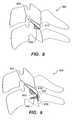
- FIG. 8shows correction of cervical stenosis or other ailment with a further embodiment of the implant of the invention, comprising a facet implant and a keel.
- FIG. 9shows correction of cervical stenosis or other ailment with a further embodiment of the implant of the invention, comprising facet implant, a keel, and screw fixation.
- FIG. 10shows correction of cervical stenosis or other ailment with a further embodiment of the implant of the invention, comprising a facet implant with teeth.
- FIG. 11depicts correction of cervical stenosis or other ailment with a further embodiment of the implant of the invention, comprising a facet implant with teeth and screw fixation.
- FIG. 12depicts correction of cervical stenosis or other ailment with a further embodiment of the implant of the invention, comprising two facet implants having bony ingrowth surfaces.
- FIG. 13depicts correction of cervical stenosis or other ailment with a further embodiment of the implant of the invention, comprising two facet implants having bony ingrowth surfaces and posterior alignment guide.
- FIG. 14shows correction of cervical stenosis or other ailment with a further embodiment of the implant of the invention, comprising two facet implants with increased facet joint contact surfaces.
- FIG. 15shows correction of cervical stenosis or other ailment with a further embodiment of the implant of the invention, comprising two facet implants having bony ingrowth surfaces and screw fixation.
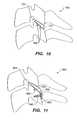
- FIG. 16shows correction of cervical stenosis or other ailment with a further embodiment of the implant of the invention, comprising two facet implants with articular inner surfaces.
- FIG. 17shows correction of cervical stenosis or other ailment with a further embodiment of the implant of the invention, comprising a facet joint implant with a roller.
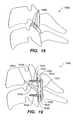
- FIG. 18shows correction of cervical stenosis or other ailment with a further embodiment of the implant of the invention, comprising a facet joint implant with a plurality of rollers.
- FIG. 19shows correction of cervical stenosis or other ailment with a further embodiment of the implant of the invention, comprising two facet joint implants, screw fixation, and elastic restraint.
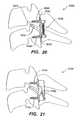
- FIG. 20shows correction of cervical stenosis or other ailment with a further embodiment of the implant of the invention, comprising two facet joint implants, screw fixation, and spring restraint.
- FIG. 21shows correction of cervical stenosis or other ailment with a further embodiment of the implant of the invention, comprising two facet joint implants, screw fixation, and magnetic restraint.
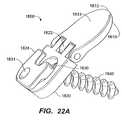
- FIG. 22Ashows a perspective view of a further embodiment of implant of the invention.
- FIG. 22Bshows a perspective exploded view of the embodiment of the invention shown in FIG. 22A .
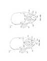
- FIG. 23Adepicts a posterior view of the embodiment of the implant of the invention shown in FIG. 22A .
- FIG. 23Bshows a posterior view of a locking plate of the embodiment of the implant of the invention shown in FIG. 22A .
- FIG. 24Adepicts a lateral side view of the embodiment of the implant of the invention shown in FIG. 22A .
- FIG. 24Bshows a lateral side view of the keel of the locking plate of the embodiment of the implant of the invention shown in FIG. 22A .
- FIG. 25Ashows a perspective view of a further embodiment of the implant of the invention.
- FIG. 25Bshows a side view of the embodiment of the implant of the invention in FIG. 25A , having a curved, uniformly-thick artificial facet joint including a tapered end
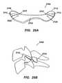
- FIG. 26Ashows a perspective view of a further embodiment of the implant of the invention having a locking cam in a first position.
- FIG. 26Bshows a perspective view of a further embodiment of the implant of the invention having a locking cam in a second position.
- FIG. 27Ashows an anterior perspective view of a further embodiment of the implant of the invention.
- FIG. 27Bshows a posterior perspective view of the embodiment of the implant of the invention depicted in FIG. 27A .
- FIG. 27Cdepicts a side view of the embodiment of the implant of the invention shown in FIGS. 26A and 26B , implanted in the cervical spine.
- FIG. 27Dshows a posterior view of the embodiment of the implant of the invention shown in FIGS. 27A , 27 B, and 27 C, implanted in the cervical spine.
- FIG. 28Adepicts a posterior perspective view of a further embodiment of the implant of the invention.
- FIG. 28Bdepicts a side view of the embodiment of the implant of the invention shown in FIG. 28A .
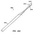
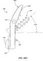
- FIG. 29Adepicts-a side view of an embodiment of a sizing tool of the invention.
- FIG. 29Bdepicts a top view of an embodiment of the sizing tool of the invention depicted in FIG. 29A .
- FIG. 29Cdepicts a perspective view of an embodiment of the sizing tool of the invention depicted in FIGS. 29A and 29B .
- FIG. 29Ddepicts a side view of the head of the sizing tool of the invention depicted in FIG. 29A
- FIG. 29Edepicts a cross-sectional view of the head of the sizing tool of the invention depicted in FIGS. 29A-29C .
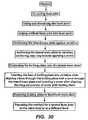
- FIG. 30is a flow diagram of an embodiment of a method of the invention.
- FIG. 31Ais posterior view of a further embodiment of the implant of the invention.
- FIG. 31Bis a side view of an embodiment of a locking screw of the implant of the invention depicted in FIG. 31A .
- FIG. 32is a posterior view of a further embodiment of the implant of the invention.
- FIGS. 33A and 33Bdepict initial and final insertion positions of the embodiment of the invention depicted in FIG. 32 .
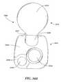
- FIGS. 34A and 34Billustrate a top and bottom plan view of an alternative embodiment of an inter-cervical facet implant in accordance with the present invention.
- FIG. 35is a partially exploded perspective view of the implant of FIGS. 34A and 34B .
- FIGS. 36A and 36Billustrate side views of the implant of FIGS. 34A and 34B illustrating a general range of motion of the implant.
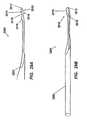
- FIG. 37is a side view of still another embodiment of an implant in accordance with the present invention.
- FIG. 38Ais a side view of still another embodiment of an implant in accordance with the present invention.
- FIG. 38Bis a top view of the implant of FIG. 38A .
- FIG. 38Cis a bottom view of the implant of FIG. 38A .
- FIG. 38D-Fare side views of the implant of FIG. 38A illustrating the various arrangements of a bone screw associated the implant.
- FIG. 38Gis an end view of the implant of FIG. 38F illustrating the arrangement of the bone screw associated the implant from an alternative viewing angle.
- FIG. 39is a side view of still another embodiment of an implant in accordance with the present invention.
- FIG. 40is a flow diagram of an alternative embodiment of a method in accordance with the present invention.
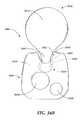
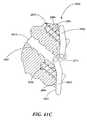
- FIG. 41Ais a perspective view of still a further embodiment of an implant in accordance with the present invention.
- FIG. 41Bis a partial cross-sectional side view of the implant of FIG. 41A arranged in position in a facet joint.
- FIG. 41Cis a partial cross-sectional side view of an alternative embodiment similar to the implant of FIG. 41A further including protuberances extending from the first and second anchoring plates.
- FIG. 41D and 41Eare perspective views of an alternative embodiment similar to the implant of FIG. 41 A further including a cam adapted to selectably obstruct a bore of the implant.
- FIG. 41Fis a side view of an alternative embodiment of an implant in accordance with the present invention.
- FIG. 41Gis a side view of an alternative embodiment of an implant in accordance with the present invention.
- FIG. 42is a flow diagram of an alternative embodiment of a method in accordance with the present invention.
- Embodiments of the present inventionprovide for a minimally invasive surgical implantation method and apparatus for cervical spine implants that preserves the physiology of the spine.
- embodimentsprovide for distracting the cervical spine to increase the foraminal dimension in extension and neutral positions.
- Such implantswhen implanted in the cervical facet joints, distract, or increase the space between, the vertebrae to increase the foraminal area or dimension, and reduce pressure on the nerves and blood vessels of the cervical spine.
- the facet joints in the spineare formed between two vertebrae as follows.
- Each vertebrahas four posterior articulating surfaces: two superior facets and two inferior facets, with a superior facet from a lower vertebra and an inferior facet of an upper vertebra forming a facet joint on each lateral side of the spine.
- the upward inclination of the superior articular surfaces of the facet jointsallows for considerable flexion and extension, as well as for lateral mobility.
- Each facet jointis covered by a dense, elastic articular capsule, which is attached just beyond the margins of the articular facets. The capsule is larger and looser in the cervical spine than in the thoracic and lumbar spine.
- the inside of the capsuleis lined by a synovial membrane which secretes synovial fluid for lubricating the facet joint.
- the exterior of the joint capsuleis surrounded by a capsular ligament. It is this ligament and the joint capsule that must be cut in the embodiments of the method described herein for inserting the artificial facet joint.
- an implanted interfacet spacer of 1.5 mm to 2.5 mm in widthcan result in interfacet distraction that increases foraminal dimension in extension and neutral.
- Other interfacet spacer dimensionsalso are contemplated by the invention described herein below.
- the present embodimentsalso preserve mobility of the facet joints.
- Embodiments of the present inventionaccommodate the distinct anatomical structures of the spine, minimize further trauma to the spine, and obviate the need for invasive methods of surgical implantation.
- Embodiments of the present inventionalso address spinal conditions that are exacerbated by spinal extension.
- FIG. 1shows a simplified diagram of a portion of the cervical spine, focusing on a cervical facet joint 1 formed between two adjacent cervical vertebrae.
- the spinous processes 3are located posteriorly and the vertebral bodies 5 are located anteriorly, and a nerve root canal 7 is visible.
- Each vertebrahas four posterior articulating surfaces: two superior facets and two inferior facets, with a superior facet from a lower vertebra and an inferior facet of an upper vertebra forming a facet joint on each lateral side of the spine.
- the upward inclination of the superior articular surfaces of the facet jointsallows for considerable flexion and extension, as well as for lateral mobility.
- Each facet jointis covered by a dense, elastic articular capsule, which is attached just beyond the margins of the articular facets.
- the capsuleis large and looser in the cervical spine than in the thoracic and lumbar spine.
- the inside of the capsuleis lined by a synovial membrane which secretes synovial fluid for lubricating the facet joint.
- the exterior of the joint capsuleis surrounded by a capsular ligament. It is this ligament that may be pushed out of the way in the embodiments of the method for inserting the artificial facet joint, described herein.
- FIG. 2depicts cervical foraminal stenosis. From the drawing, the nerve root canal 7 is narrowed relative to the nerve root canal 7 depicted in FIG. 1 .
- the spinal canal and/or intervertebral foraminaalso can be narrowed by stenosis. The narrowing can cause compression of the spinal cord and nerve roots.
- FIG. 3Ashows a first embodiment 100 of the present invention, which is meant to distract at least one facet joint, in order to increase the dimension of the neural foramen while retaining facet joint mobility.
- the wedge-shaped embodiment 100is a wedge-shaped implant that can be positioned in the cervical facet joint 101 to distract the joint and reverse narrowing of the nerve root canal 107 .
- the implantis positioned with the narrow portion of the wedge facing anteriorly.
- the embodiment 200 of the implanthas a joint insert or spacer 210 , also herein referred to as an artificial facet joint, that is positioned in the cervical facet joint 101 .
- the joint insert or spacer 210can be wedge-shaped with the narrow part of the wedge facing anteriorly.
- the joint insert or spacer 210need not be wedge-shaped but can be of substantially uniform thickness, the thickness determined by an individual patient's need for distraction of the cervical facet joint 201 .
- one objective of this embodimentis facet joint distraction, and joint mobility after implantation.
- the joint insert or spacer 210is continuous with a posterior sheath 220 bent at an angle from the joint insert or spacer 210 to align substantially parallel with the bone.
- the posterior sheathcan lie against the lamina, preferably against the lateral mass.
- the posterior sheath 220can have a bore 230 which can accept a bone screw 240 .
- the bore 230can accept any other appropriate and/or equivalent fixation device capable of fixing the embodiment 200 to the spine.
- the deviceis thereby affixed to the vertebra, preferably by fixing to the lateral mass.
- FIG. 5shows embodiment 300 , which is the use of two embodiments 200 , each fixed to one of two adjacent cervical vertebrae.
- the implanted facet jointis distracted and joint mobility is retained.
- a joint insert or spacer 310 from each of the two implantsis inserted and positioned in the cervical facet joint 301 .
- the joint inserts or spacers 310are substantially flat and parallel to each other and are not wedge-shaped.
- the joint inserts or spacers 310can together define a wedge-shaped insert that is appropriate for the patient.
- the two joint inserts or spacers 310 combinedcan have, by way of example, the shape of the joint insert or spacer 210 in FIG. 4 .
- Embodiment 300then can be fixed to the spine with a screw 340 or any other appropriate fixation device, inserted through a bore 330 in the posterior sheath 320 .
- the posterior sheath 320can be threaded to accept a screw.
- the screwcan be embedded in the lamina, preferably in the lateral mass, where possible.
- FIG. 6depicts a cervical spine lordosis.
- FIG. 7demonstrates an embodiment 400 which contemplates positioning two implants to correct for this spinal abnormality while retaining facet joint mobility.
- the joint insert or spacer 410 of each implantis shaped so that it is thicker at its anterior portion.
- the implantscan be shaped to be thicker at the posterior ends, for example as depicted in FIG. 3A .
- each implantis bent at an angle from the joint insert or spacer 410 to be positioned adjacent to the lateral mass and/or lamina, and has a bore 430 to accept a screw 440 or other appropriate and/or equivalent fixation means to fix the embodiment 400 to the spine, preferably to the lateral mass.
- the placement of two joint inserts or spacers 410 in the cervical facet joint 401distracts the facet joint, which shifts and maintains the vertebrae into a more anatomical position to preserve the physiology of the spine.
- FIG. 8shows a further embodiment 500 of the implant of the invention, wherein the joint insert or spacer 510 has a keel 550 on an underside of the joint insert or spacer 510 .
- the keel 550can be made of the same material or materials set forth above. The surfaces of the keel 550 can be roughened in order to promote bone ingrowth to stabilize and fix the implant 500 .
- the keel 550can be coated with materials that promote bone growth such as, for example, bone morphogenic protein (“BMP”), or structural materials such as hyaluronic acid “HA,” or other substances which promote growth of bone relative to and into the keel 550 .
- BMPbone morphogenic protein
- HAhyaluronic acid
- the keel 550can be embedded in the facet bone, to facilitate implant retention.
- the keel 550can be placed into a channel in the facet bone.
- the channelcan be pre-cut.
- Teeth(not shown), preferably positioned posteriorly, also may be formed on the keel 550 for facilitating retention of the implant 500 in the cervical facet joint 501 .
- the joint insert or spacer 510can be substantially flat or wedge-shaped, depending upon the type of distraction needed, i.e., whether distraction is also necessary to correct abnormal curvature or lack of curvature in the cervical spine. Because the joint is not fused, mobility is retained, as with the embodiments described above and herein below.
- FIG. 9illustrates that a further embodiment 600 of the implant of the invention can have both screw fixation and a keel 650 for stability and retention of the implant 600 .
- the joint insert or spacer 610is continuous with a posterior sheath 620 having a bore hole 630 to accept a screw 640 which passes through the bore 630 and into the bone of the vertebrae, preferably into the lateral mass, or the lamina.
- the bore 630can be threaded or not threaded where it is to accept a threaded screw or equivalent device. Alternatively, the bore 630 need not be threaded to accept a non-threaded equivalent device.
- the keel 650is connected with the joint insert or spacer 610 and embeds in the bone of the cervical facet joint 601 to promote implant retention.
- FIG. 10A further alternative embodiment 700 is illustrated in FIG. 10 .
- the joint insert or spacer 710has on a lower side at least one tooth 760 .
- a plurality of teeth 760is preferable.
- the teeth 760are able to embed in the bone of the cervical facet joint 701 to facilitate retention of the implant 700 in the joint 701 .
- the teeth 760can face in a direction substantially opposite the direction of insertion, for retention of the implant 700 .
- the joint insert or spacer 710can be wedge-shaped or substantially even in thickness, depending upon the desired distraction. Because the implant distracts and is retained without fusion, facet joint mobility is retained.
- FIG. 11depicts a further embodiment 800 of the implant of the invention.
- the joint insert or spacer 810is continuous with a posterior sheath 820 having a bore 830 for accepting a fixation device 840 , as described above.
- the fixation device 840can be a screw which fits into a threaded bore 830 ; alternatively, the fixation device 830 can be any other compatible and appropriate device.
- This embodiment 800further combines at least one tooth 860 on an underside of the joint insert or spacer 810 with the posterior sheath 820 , bore 830 and fixation device 840 to address fixation of the implant 800 in a cervical facet joint 801 .
- the implant 800can have a plurality of teeth 860 on the underside of the joint insert or spacer 810 .
- FIG. 12shows yet another embodiment 900 of an implant of the present invention.
- the joint inserts or spacers 910 of two implants 900are positioned in a cervical facet joint 901 .
- the joint inserts or spacers 910can be wedge-shaped as needed to restore anatomical curvature of the cervical spine and to distract, or the joint inserts or spacers 910 can be of substantially uniform thickness.
- the implants 900each comprise a joint insert or spacer 910 with an outer surface 970 that interacts with the bone of the cervical facet joint 901 .
- the surface 970 that interacts with the boneis the upper surface 970 and on the lower implant 900 , the surface 970 that interacts with the bone is the lower surface 970 .
- Each surface 970can comprise a bone ingrowth surface 980 to create a porous surface and thereby promote bone ingrowth and fixation.
- One such treatmentcan be with plasma spray titanium, and another, with a coating of sintered beads.
- the implant 900can have casted porous surfaces 970 , where the porous surface is integral to the implant 900 .
- the surfaces 970can be roughened in order to promote bone ingrowth into these defined surfaces of the implants 900 .
- the surfaces 970can be coated with materials that promote bone growth such as for example bone morphogenic protein (“BMP”), or structural materials such as hyaluronic acid (“HA”), or other substances which promote growth of bone on other external surfaces 970 of the implant 900 .
- BMPbone morphogenic protein
- HAhyaluronic acid
- FIG. 13depicts yet another embodiment 1000 of the implant of the present invention.
- the joint inserts or spacers 1010 of two implants 1000are positioned in a cervical facet joint 1001 .
- the joint inserts or spacers 1010can be wedge-shaped as needed to restore anatomical curvature of the cervical spine and to distract, or the joint inserts or spacers 1010 can be of substantially uniform thickness.
- the implants 1000each comprise a joint insert or spacer 1010 with an outer surface 1070 that interacts with the bone of the cervical facet joint 1001 .
- the surface 1070 that interacts with the boneis the upper surface and on the lower implant 1000 , the surface 1070 that interacts with the bone is the lower surface.
- each outer surface 1070can comprise a bone ingrowth surface 1080 to create a porous surface and thereby promote bone ingrowth and fixation, without facet joint fusion and loss of mobility.
- the bone ingrowth surface 1080can be created with plasma spray titanium, and/or with a coating of sintered beads.
- the implant 1000can have casted porous surfaces 1070 , where the porous surface is integral to the implant 1000 .
- the surfaces 1070can be roughened in order to promote bone ingrowth into these defined surfaces of the implants 1000 .
- the surfaces 1070can be coated with materials that promote bone growth such as for example BMP, or structural materials such as HA, or other substances which promote growth of bone on other external surfaces 1070 of the implant 1000 .
- the implant 1000can have a posterior alignment guide 1090 .
- the posterior alignment guides 1090 of each implant 1000can be continuous with the joint inserts or spacers 1010 .
- the posterior alignment guidessubstantially conform to the bone of the vertebrae when the joint inserts or spacers 1010 are inserted into the cervical facet joint 1001 .
- the posterior alignment guides 1090are used to align the implants 1000 so that the joint inserts or spacers 1010 contact each other and not the bones of the cervical facet joint 1001 when the joint inserts or spacers 1010 are positioned in the cervical facet joint 1001 .
- FIG. 14depicts a further embodiment 1100 of the implant of the present invention.
- the joint inserts or spacers 1110 of two implants 1100are inserted into the cervical facet joint 1101 .
- Each of the joint inserts or spacers 1110is continuous with a cervical facet joint extender or facet-extending surface 1192 .
- the bone contacting surfaces 1170 of the joint inserts or spacers 1110are continuous with, and at an angle to, the bone contacting surfaces 1193 of the cervical facet joint extenders 1192 , so that the cervical facet joint extenders 1192 conform to the bones of the vertebrae exterior to the cervical facet joint 1101 .
- the conformity of the cervical facet joint extenders 1192is achieved for example by forming the cervical facet joint extenders 1192 so that when the join inserts 1110 are positioned, the cervical facet joint extenders 1192 curve around the bone outsider the cervical facet joint 1101 .
- the cervical facet joint extendershave a second surface 1184 that is continuous with the joint articular surfaces 1182 of the joint inserts or spacers 1110 .
- the second surfaces 1184extend the implant 1100 posteriorly to expand the joint articular surfaces 1182 and thereby to increase contact and stability of the spine at least in the region of the implants 1100 . It is to be understood that such facet joint extenders 1192 can be added to the other embodiments of the invention described and depicted herein.
- each of two implants 1200has a joint insert or spacer 1210 positioned in a cervical facet joint 1201 .
- the joint inserts or spacers 1210can be wedge-shaped as needed to restore anatomical curvature of the cervical spine and to distract, or the joint inserts or spacers 1210 can be of substantially uniform thickness.
- the implants 1200each comprise a joint insert or spacer 1210 with an outer surface 1270 that interacts with the bone of the cervical facet joint 1001 .
- each outer surface 1270can comprise a bone ingrowth surface 1280 to create a porous surface and thereby promote bone ingrowth and fixation.
- the bone ingrowth surface 1280can be created with plasma spray titanium, and/or with a coating of sintered beads.
- the implant 1200can have casted porous surfaces 1270 , where the porous surface is integral to the implant 1200 .
- the surfaces 1270can be roughened in order to promote bone ingrowth into these defined surfaces of the implants 1200 .
- the surfaces 1270can be coated with materials that promote bone growth such as for example BMP, or structural materials such as HA, or other substances which promote growth of bone on other external surfaces 1270 of the implant 1200 .
- Screw fixation or other appropriate fixationalso can be used with implants 1200 for fixation in the cervical facet joint 1201 .
- the joint insert or spacer 1210is continuous with a posterior sheath 1220 bent at an angle from the joint insert or spacer 1210 to align substantially parallel with the bone, preferably the lateral mass or lamina.
- the posterior sheath 1220can have a bore 1230 which can accept a bone screw 1240 , preferably into the lateral mass or lamina.
- the bore 1230can accept any other appropriate and/or equivalent fixation means for fixing the embodiment 1200 to the spine.
- FIG. 16depicts a further preferred embodiment of the present invention.
- two joint inserts or spacers 1310are positioned in the cervical facet joint 1301 .
- the joint inserts or spacerseach have outer surfaces 1370 that interact with the bone of the vertebrae forming the cervical facet joint.
- These outer surfaces 1370 of the embodiment 1300can be treated to become bone ingrowth surfaces 1380 , which bone ingrowth surfaces 1380 contribute to stabilizing the two joint inserts or spacers 1310 of the implant 1300 .
- the bone ingrowth surface 1380can be created with plasma spray titanium, and/or with a coating of sintered beads.
- the implant 1300can have casted porous surfaces 1370 , where the porous surface is integral to the implant 1300 .
- the surfaces 1370can be roughened in order to promote bone ingrowth into these defined surfaces of the implants 1300 .
- the surfaces 1370can be coated with materials that promote bone growth such as for example BMP, or structural materials such as HA, or other substances which promote growth of bone on other external surfaces 1370 of the implant 1300 . This fixation stabilizes the implant 1300 in the facet joint without fusing the joint, and thus the implant preserves joint mobility, while accomplishing distraction and increasing foraminal dimension.
- the embodiment 1300 of FIG. 16can be made in at least two configurations.
- the first configurationincludes a flexible spacer 1382 made, by way of example, using polyethylene or other suitable, flexible implant material.
- the flexible spacer 1382can be permanently affixed to the upper and lower joint insert or spacer 1310 .
- the spacer 1382can be flat or wedge-shaped or have any other shape that would correct the curvature of the spine.
- the spacer 1382can be affixed to only the upper insert 1310 or to only the lower insert 1310 .
- a spacer 1382can be affixed to each of an upper insert 1310 and a lower insert 1310 with the upper insert 1310 and the lower insert 1310 being separate units.
- FIG. 17shows a further preferred embodiment of the implant of the present invention.
- the implanthas a roller 1496 mounted on a joint insert or spacer 1410 , the roller being a further means of preserving joint mobility while accomplishing distraction.
- Both the roller 1496 and the joint insert or spacer 1410are positioned in the cervical facet joint 1401 .
- the joint insert or spacer 1410as in other embodiments has a bone-facing surface 1470 and joint articular surface 1482 .
- the bone-facing surface 1470can interact with the lower bone of the cervical facet joint 1401 .
- the bone-facing surfacecan interact with the upper bone of the cervical facet joint 1401 .
- roller 1496rotates in a cavity in the joint insert or spacer 1410 , and interacts with the top bone of the cervical facet joint 1401 .
- the roller 1496rotates in a cavity in the joint insert or spacer 1410 and interacts with the lower bone of the cervical facet joint 1401 .
- the rotation of the roller 1496allows flexion and extension of the cervical spine.
- a rollersuch as roller 1496 can be secured to an upper and a lower insert such as inserts 410 in FIG. 7 .
- a plurality of rollers 1496also is possible.
- FIG. 19depicts a further embodiment of the implant of the present invention.
- two implants 1500are implanted in the cervical facet joint 1501 .
- Screw fixation or other appropriate fixationis used with implants 1500 for fixation in the cervical facet joint 1501 .
- the joint insert or spacer 1510is continuous with a posterior sheath 1520 bent at an angle from the joint insert or spacer 1510 to align substantially parallel with the bone, preferably the lateral mass or lamina.
- the posterior sheath 1520 of each implant 1500can have a bore 1530 which can accept a bone screw 1540 , preferably into the lateral mass or lamina.
- the bore 1530can accept any other appropriate and/or equivalent fixation means for fixing the embodiment 1500 to the spine.
- the head of the screw 1540 in each posterior sheath 1520 of each implant 1500has a groove 1598 or other mechanism for retaining an elastic band 1597 .
- the elastic band 1597is looped around each of the two screws 1540 to restrain movement of the cervical spine without eliminating facet joint mobility.
- the band 1597preferably can restrain flexion and lateral movement.
- the elastic band 1597can be made of a biocompatible, flexible material.
- FIG. 20shows an alternative to use of an elastic band as in FIG. 19 .
- the elastic bandis replaced with a spring restraint 1699 , which extends between the heads of two screws 1640 , one screw fixing each of two implants 1600 in the cervical facet joint 1601 .
- FIG. 21shows another alternative to using an elastic band and/or a spring as in FIGS. 19 or 20 .
- magnets 1795is used for restraint between the two screws 1740 .
- the magnet 1795can either be comprised of two opposing magnetic fields or two of the same magnetic fields to operate to restrain movement.
- the head of one of the two screws 1740is magnetized, and the head of the other screw 1740 is magnetized with either the same or opposite field. If the magnets 1795 have the same polarity, the magnets 1795 repel each other and thus limit extension. If the magnets 1795 have opposite polarities, the magnets 1795 attract each other and thus limit flexion and lateral movement.
- FIGS. 22A-24Bdepict a further embodiment 1800 of the implant of the present invention.
- a natural or artificial facet joint spacer (or insert) or inter-facet spacer (or insert) 1810is connected with a lateral mass plate (also referred to herein as an anchoring plate) 1820 with a hinge 1822 .
- the hinge 1822allows the lateral mass plate 1820 to bend at a wide range of angles relative to the artificial facet joint and preferably at an angle of more than 90 degrees, and this flexibility facilitates positioning and insertion of the facet joint spacer (or insert) 1810 into a patient's facet joint, the anatomy of which can be highly variable among individuals.
- the hinge 1822further facilitates customizing the anchoring of the implant, i.e., the positioning of a fixation device.
- the hingeenables positioning of the lateral mass plate 1820 to conform to a patient's cervical spinal anatomy, and the lateral mass plate 1820 accepts a fixation device to penetrate the bone.
- the facet joint spacer (or insert) 1810can be curved or rounded at a distal end 1812 ( FIG. 23A ), and convex or dome-shaped on a superior surface 1813 to approximate the shape of the bone inside the facet joint.
- the inferior surface 1815can be flat or planar. Alternatively, the inferior surface 1815 can be concave. As another alternative, the inferior surface 1815 can be convex.
- the lateral mass plate 1820when implanted in the spine, is positioned outside the facet joint, preferably against the lateral mass or against the lamina.
- the lateral mass plate 1820has a bore 1830 therethrough.
- the bore 1830can accept a bone screw 1840 , also referred to as a lateral mass screw, to secure the lateral mass plate 1820 preferably to the lateral mass or alternatively to another part of the spine, and thus to anchor the implant.
- the lateral mass screw 1840preferably has a hexagonal head to accept an appropriately-shaped wrench. As described below, the head accepts a compatible probe 1826 from a locking plate 1824 .
- the locking plate 1824includes a keel 1828 with a wedge shaped distal end to anchor the implant, preferably in the lateral mass or in the lamina, outside the facet joint and to prevent rotation of the lateral mass plate 1820 and the locking plate 1824 .
- the keel 1828aligns with a groove 1823 through an edge of the lateral mass plate 1820 to guide and align the keel 1828 as the keel 1828 cuts into a vertebra.
- the locking plate 1824includes a probe 1826 that fits against the head of the lateral mass screw 1840 .
- the locking platefurther includes a bore 1831 that can accept a machine screw (not shown) which passes through to an aligned bore 1829 in the lateral mass plate 1820 to hold the locking plate 1824 and the lateral mass plate 1820 together without rotational displacement relative to each other.
- the locking plate 1824thus serves at least two functions: (1) maintaining the position of the lateral mass screw 1840 with the probe 1826 , so that the screw 1840 does not back out; and (2) preventing rotation of the implant with the keel 1828 and machine screw relative to the cervical vertebra or other vertebrae.
- the locking plate 1824can include a probe with barbs that can be inserted into a port in the lateral mass plate. The barbs can become engaged in ribs that define the side walls of the port in the lateral mass plate
- the lateral mass plate 1920includes a recessed area 1922 for receiving the locking plate 1924 so that the locking plate 1924 is flush with the upper surface 1925 of the lateral mass plate 1920 when the probe 1926 is urged against the lateral mass screw 1940 and the keel 1928 is inserted into the lateral mass or the lamina of the vertebra.
- the shape and contours of the facet joint spacer (or insert) 1910can facilitate insertion of the facet joint spacer 1910 into the cervical facet joint.
- the facet joint spacer 1910has a rounded distal end 1912 .
- the distal end 1912is tapered in thickness to facilitate insertion.
- the tapered distal end 1912meets and is continuous with a proximal mid-section 1916 which, in this preferred embodiment, has a uniform thickness, and is connected flexibly, preferably with a hinge 1922 , to the lateral mass plate 1920 , as described above.
- the facet joint spacer 1910with its proximal mid-section 1916 and tapered distal end 1912 , is curved downward, causing a superior surface 1913 of the facet joint spacer 1910 to be curved.
- the curvecan cause the superior surface 1913 to be convex, and the convexity can vary among different implants 1900 to suit the anatomical structure of the cervical facet joint(s) of a patient.
- An inferior surface 1915accordingly can be preferably concave, flat, or convex.
- the curved shape of the implantcan fit the shape of a cervical facet joint, which is comprised of an inferior facet of an upper vertebra and a superior facet of a lower adjacent vertebra.
- the convex shape of the superior surface 1913 of the facet joint spacer 1910fits with a concave shape of the inferior facet of the upper cervical vertebrae.
- the concave shape of the inferior surface 1915 of the facet joint spacer 1910fits with the convex shape of the superior facet of the cervical vertebrae.
- the degree of convexity and concavity of the facet joint spacer inferior and superior surfacescan be varied to fit a patient's anatomy and the particular pairing of adjacent cervical vertebrae to be treated.
- a less-curved facet joint spacer 1910can be used where the patient's cervical spinal anatomy is sized (as described below) and found to have less convexity and concavity of the articular facets.
- the input for the right and left facet jointwill be similarly shaped. It is expected that the similarity of shape of the facet joint spacer and the smooth, flush surfaces will allow distraction of the facet joint without loss of mobility or damage to the bones of the cervical spine.
- the width of the mid-section 1916is from 1.5 mm to 2.5 mm.
- a cam 3824can be rotatably associated with the lateral mass plate 3820 so that the first bore 3830 can be selectably obstructed or unobstructed, thereby allowing a bone screw 3840 to be received within the first bore 3830 , or resisting movement of the bone screw 3840 seated within the first bore 3830 .
- the cam 3824can have a shape such that at a first position the surface 3828 of the cam is approximately flush with the first bore 3830 , thereby allowing a bone screw 3840 to pass through the first bore 3830 .
- a protruding portion 3826 of the surface of the cam 3824can extend across at least a portion of the first bore 3830 , thereby blocking a bone screw 3840 seated within the first bore 3830 and preventing the bone screw 3840 from backing out of the first bore 3830 .
- the cam 3824can include features 3831 (e.g., indentations) that can allow the cam to be grasped with a tool (not shown), and thus rotated to the desired position. As shown, the cam 3824 is positioned within a slot of the lateral mass plate 3820 so that the cam does not protrude undesirably from the surface of the lateral mass plate 3820 .
- FIGS. 22A-24Bis similar to the embodiment shown in FIGS. 25A-26B . Accordingly the remaining elements on the 1900 series of element numbers is preferably substantially similar to the described elements in the 1800 series of element numbers, as set forth above. Thus, by way of example, elements 1923 , 1928 , 1929 and 1930 are similar, respective elements 1823 , 1828 , 1829 and 1830 .
- FIG. 30is a flow chart of the method of insertion of an implant of the invention.
- the embodiment 1800 or 1900 of the present inventionpreferably is inserted in the following manner (only elements of the embodiment 1800 will be set forth herein, for purposes of the written description of a method of the invention).
- a sizing tool 2200(see FIGS. 29A-C ) can be inserted to select the appropriate size of an implant of the invention for positioning in the cervical facet joint. This step may be repeated as necessary with, if desired, different sizes of the tool 2200 until the appropriate size is determined. This sizing step also distracts the facet joint and surrounding tissue in order to facilitate insertion of the implant.
- the facet joint spacer (or insert) 1810is urged between the facets into the facet joint.
- the facet itselfis somewhat shaped like a ball and socket joint. Accordingly, in order to accommodate this shape, the artificial joint 1810 can have a rounded leading edge shaped like a wedge or tissue expander to cause distraction of the facet joint as the facet joint spacer is urged into the facet joint of the spine.
- the facet joint spacer 1810also includes the convex surface 1813 in order to more fully accommodate the shape of the facet joint of the spine.
- a curve-shaped facet joint spacer (or insert) 1910with a convex superior surface 1913 and a concave inferior surface 1915 , the distal end 1912 tapering to facilitate insertion, while the remainder of the facet joint spacer 1910 , (i.e., the proximal section 1916 ) has a uniform thickness.
- the lateral mass plate 1820is pivoted downward about the hinge 1822 adjacent to the vertebrae and preferably to the lateral mass or to the lamina.
- the lateral mass plate 1820may be disposed at an angle relative to the facet joint spacer 1810 for a representative spine configuration. It is to be understood that as this embodiment is hinged the final position of the lateral mass plate 1820 relative to the facet joint spacer 1800 will depend on the actual spine configuration. It is to be understood that embodiments of the invention can be made without a hinge, as long as the connection between the facet joint spacer and the lateral mass plate is flexible enough to allow the lateral mass plate to be bent relative to the facet joint spacer in order to fit the anatomy of the patient.
- a borecan be drilled in the bone to accommodate the bone screw 1824 .
- the screw 1824can be self-tapping.
- the screwis then placed through the bore 1830 and secured to the bone, preferably the lateral mass or the lamina, thereby holding the facet joint spacer 1800 in place.
- the locking plate 1824is positioned over the lateral mass plate 1820 . So positioned, the probe 1826 is positioned through the bore 1830 and against the head of the bone screw to keep the bone screw from moving.
- the keel 1828having a sharp chisel-shaped end, preferably can self-cut a groove in the bone so that the keel 1828 is locked into the bone as the keel 1828 is aligned by, and received in, a groove 1831 of the lateral mass plate 1820 .
- a groovecan be pre-cut in the bone to receive the keel 1828 .
- the bore 1829 of the locking plate 1824aligns with the threaded bore 1831 of the lateral mass plate 1820 and a machine screw can be inserted to lock the locking plate relative to the lateral mass plate.
- the implantis between the C5 and C6 vertebrae level, or the C6 and C7 vertebrae level.
- two implantspreferably will be implanted at each level between vertebrae. That is, an implant 1800 will be placed in a right facet joint and also in a left facet joint when viewed from a posterior view point. This procedure can be used to increase or distract the foraminal area or dimension of the spine in an extension or in neutral position (without having a deleterious effect on cervical lordosis) and reduce the pressure on the nerves and blood vessels. At the same time this procedure preserves mobility of the facet joint.
- FIGS. 27A-27Dshow a further embodiment of the implant of the invention, with the embodiment 2000 implanted in the cervical spine as depicted in FIGS. 27C and 27D .
- the implant 2000comprises a first facet joint spacer (or insert) 2010 and a second facet joint spacer 2010 .
- Each facet joint spacercan have a distal end 2012 that is tapered or wedge-shaped in a way that facilitates insertion into the cervical facet joints on both sides of two adjacent cervical vertebrae at the same level.
- the facet joint spacersfurther can be dome-shaped, or convex on a superior surface 2013 , to approximate the shape of the cervical facets of the cervical facet joints.
- the first and second facet joint spacers 2010are bridged together by a collar 2015 .
- the collar 2015passes between the spinous processes of the adjacent cervical vertebrae.
- the implantcan preferably be “V” shaped or “boomerang” shaped.
- the entire implant 2000 or the collar 2015 of the implantcan be made of a flexible material such as titanium, so that it is possible to bend the collar 2015 so that it conforms preferably to the shape of the lateral mass or the lamina of the cervical vertebrae of the patient and thereby holds the implant in place with the facet joint spacers (or inserts) 2010 inserted in the cervical facet joints.
- Bores 2029are preferably are provided through implant 2000 adjacent to the facet joint spacer 2010 respectively.
- bores 2029can receive bone screws to position the implant 2000 against the lateral mass or the lamina as shown in FIGS. 27C , 27 D.
- the description of the embodiment 2100 , in FIGS. 28A , 28 Bprovide further details concerning the method of affixing the implant 2000 to the vertebrae.
- the implant 2100also can be made of PEEK or other materials as described herein.
- Embodiment 2000(the “boomerang” shape depicted in FIG. 27D ) further can have a locking plate as, for example, the locking plate 1824 in FIG. 22A .
- the locking plate for embodiment 2000can have the same features as locking plate 1824 , that is: (1) a probe 1826 that interacts with the bone screws to prevent the bone screws from backing out of the bone, the likely consequence of which would be displacement of the implant 2000 ; and (2) a keel 1828 with a chisel end to embed in the bone and thus to prevent rotational displacement of the implant.
- a chiselmay not serve the same purpose as with the embodiments set forth above, which lack a collar stabilized by two bone screws. Therefore, a locking plate on embodiment 2000 can be provided without a keel.
- FIGS. 28A and 28Bdepict a further embodiment of the implant of the invention 2100 .
- the collar 2115can be made of a flexible material such as titanium, of a substantially inflexible material, or of other materials described herein. Substantial flexibility can also be derived from connecting a first facet joint spacer (or insert) 2110 with the collar 2115 using a first hinge 2117 , and connecting a second facet joint spacer 2110 with the collar 2115 using a second hinge 2117 . Using the first hinge 2117 and the second hinge 2117 , the collar 2115 can be pivoted downward to conform to a particular patient's cervical spinal anatomy. In other words, the degree of pivoting will vary among different patients, and the first hinge 2117 and second hinge 2117 allow the implant 2100 to accommodate the variance.
- the collar 2115can have a first bore 2129 inferior to the first hinge 2117 , and a second bore 2129 inferior to the second hinge 2117 .
- a first bone screwpenetrates the first bore 2130 and into the lateral mass or the lamina
- the second bone screwpenetrates the second bore 2130 and into the lateral mass or the lamina, the first and second bone screws serving to anchor the implant.
- a bore, preferably in the lateral mass,can be drilled for the first bone screw and for the second bone screw.
- the bone screwscan be self-tapping.
- a first locking platesimilar to the plate 1924 ( FIG.
- the first locking platecan block the first bone screw with a probe and the second locking plate can block to the second bone screw with a probe.
- embodiments 2000 and 2100also can be configured for accommodating treatment of cervical spinal stenosis and other cervical spine ailments where only a single cervical facet joint between adjacent vertebrae requires an implant, i.e., where treatment is limited to one lateral facet joint.
- the collar 2015 , 2115extends medially without extending further to join a second facet joint spacer 2010 , 2110 .
- the implantcomprises a single hinge 2117 , and the collar 2115 has only one bore 2129 to accept one bone screw to secure the implant 2100 .
- FIGS. 29A-Edepict a sizing and distracting tool 2200 of the invention.
- Sizing tool 2200has a handle 2203 and a distal head 2210 that is shaped as a facet joint spacer (e.g., 1810 ) of an implant of the invention. That is, the head 2210 preferably will have essentially the same features as the facet joint spacer 1810 , but the dimensions of the head 2210 will vary from one tool 2200 to the next, in order to be able to use different versions of the sizing tool 2200 to determine the dimensions of the cervical facet joint that is to be treated and then to select an appropriately-sized implant.
- the head 2210preferably can be used to distract the facet joint prior to the step of implanting the implant in the facet joint.
- the head 2210is rounded at the most distal point 2212 , and can be a tapered to facilitate insertion into a cervical facet joint.
- the head 2210also can have a slightly convex superior surface 2213 , the degree of convexity varying among different sizing tools 2200 in order to determine the desired degree of convexity of an implant to be implanted in the cervical facet joint.
- the head 2210may have a uniform thickness along a proximal mid-section 2216 .
- the inferior surface 2215preferably can be concave.
- the proximal mid-section 2212may be convex on the superior surface 1813 without being uniform in thickness.
- the inferior surface 2215can be flat or planar.
- the headalso can be curved.
- the head 2210has a stop 2218 to prevent over-insertion of the head 2210 of the sizing tool 2200 into the facet joint.
- the stop 2218can be a ridge that separates the head 2210 from the handle 2203 .
- the stop 2218can be any structure that prevents insertion beyond the stop 2218 , including pegs, teeth, and the like.
- Different sizing tools 2200 covering a range of dimensions of the head 2210can be inserted successively into a cervical facet joint to select the appropriate size of an implant to position in the cervical spine, with the appropriate convexity and concavity of facet joint spacer. Each preferably larger head also can be used to distract the facet joint.
- FIG. 31Adepicts a posterior view of a further embodiment 2300 of the implant of the invention.
- Embodiment 2300as well as all of the embodiments herein, can benefit from some or all of the advantages described herein with regard to the other embodiments described herein.
- embodiment 2300has a facet joint spacer (or insert) 2310 that can have a tapered or thinned distal end 2312 so that the distal end 2312 facilitates insertion of the facet joint spacer 2310 into a cervical facet joint.
- the distal end 2312can be rounded, as seen in the plan view of FIG. 31A , in order to conform to the roundness of the facet joint.
- the facet joint spacer 2310further can be curved so that a superior surface 2313 of the facet joint spacer 2310 is convex, and an inferior surface 2315 is concave, to approximate the natural shape of the cervical facet joint that is to receive the implant 2300 .
- the curvecan have a uniform thickness, or it can have a varied thickness.
- the lateral edges of the facet joint spacer 2310are curved or rounded, for distribution of load-bearing stress.
- the facet joint spacer 2310also can be made of a flexible, biocompatible material, such as PEEK, to maintain joint mobility and flexibility.
- the facet joint spacer 2310is connected flexibly with a lateral mass plate 2320 , the flexible connection preferably being a hinge 2322 .
- the implant 2300is substantially hour-glass shaped. This shape, as well as the shape of FIG. 32 , will be discussed further below.
- the hinge 2322is narrower than the facet joint spacer (or insert) 2310 , with the hinge 2322 sitting at substantially the isthmus 2317 between facet joint spacer 2310 and the lateral mass plate 2320 .
- the curved edges, or fillets, about the hinge 2322serve to distribute more evenly the load-bearing stress on the implant 2300 , and thus prevent concentrating the stress about the edges.
- the hinge 2322allows the implant 2300 to bend at the hinge 2322 , bringing a lateral mass plate 2320 adjacent to the lateral mass and/or lamina of the patient's spine, and to conform to a particular patient's anatomy.
- the lateral mass plate 2320is made of a biocompatible flexible material, preferably titanium or any other biocompatible flexible material as described herein, for example PEEK, that will support the use of bone screws and other hardware, as described below.
- the lateral mass plate 2320bends downward at the hinge 2322 over a wide range of angles relative to the facet joint spacer 2310 , and preferably at an angle of more than 90 degrees, and this flexibility facilitates positioning and insertion of the facet joint spacer.
- a first bone screwsuch as bone screw 1840 , can be inserted through a first bore 2330 through the lateral mass plate 2320 and embedded into the bone of the lateral mass of the cervical vertebra.
- the lateral mass plate 2320further comprises a second bore 2329 which is preferably positioned medially, relative to the first bore 2330 .
- the second bore 2329 in the lateral mass plate 2320can be positioned either to the left or to the right of the first bore 2330 .
- the position of the second bore 2329will depend upon whether the implant 2300 is intended to be inserted into a cervical facet joint on the left or right side of a patient. Specifically, an implant 2300 to be inserted into a right-side cervical facet joint (i.e., the patient's rights side) will have a second bore 2329 positioned to the left of the first bore 2330 as in FIG.
- the second bore 2329 through the lateral mass plate 2320is adapted to accept a second screw 2390 ( FIG. 31B ), which preferably is a locking screw with a chisel point 2391 .
- the locking screw 2390is received by the second bore 2329 and the chisel point 2391 self-cuts a bore into the bone.
- the locking screw 2390preferably is inserted through the second bore 2329 and embedded in the bone, after the bone screw is embedded in the bone through the first bore 2330 .
- the position of the second bore 2329i.e., medial to the first bore 2330 , positions the locking screw 2390 so that it embeds in stronger bone tissue than if the second bore 2329 were located more laterally.
- the locking screwin combination with the bone screw, prevents rotational and/or backward displacement of the implant 2300 .
- the head 2392 of the locking screw 2390aligns with the head of the first bone screw in the first bore 2330 , blocking the head of the first bone screw to prevent the first bone screw from backing out of the bone of the vertebra and the first bore 2330 .
- FIG. 32depicts a further embodiment 2400 of the implant of the invention, from a posterior view.
- Embodiment 2400is adapted to be implanted in a manner that preserves the anatomy of the cervical facet joint, in particular, the soft tissues around the cervical facet joint, including the joint capsule.
- Implant 2400like implant 2300 and other implants disclosed above, has a facet joint spacer 2410 , flexibly connected, preferably by a hinge 2422 , to a lateral mass plate 2420 .
- the implant 2400 including the facet joint spacer (or insert) 2410 and the hinge 2422is substantially “P” shaped. As explained below, its “P” shape assists in the insertion of the implant 2400 into the facet joint with most of the facet capsule and facet capsule ligament and other soft tissue associated with the facet joint still left intact.
- the facet joint spaceras above for implant 2300 and the other implants disclosed above, can have a superior surface 2413 of the facet joint spacer 2410 that is convex, and an inferior surface 2415 that is concave, or any appropriate shaping to approximate the natural shape of the cervical facet joint that is to receive the implant 2400 .
- the thickness of the facet joint spacer 2410can be uniform, or varied.
- the facet joint spacer 2410also can be made of a flexible, biocompatible material, such as PEEK, to maintain joint mobility and flexibility.
- the hinge 2422can have smooth, rounded edges, for distribution of load stress, as disclosed above. Other features and advantages of the other embodiments can be, if desired, incorporated into the design of the embodiment of FIG. 32 .
- the facet joint spacer 2410further can have a tapered or thinned edge 2412 so that the edge 2412 facilitates insertion of the facet joint spacer 2410 into a cervical facet joint.
- the edge 2412can be curved.
- the thinned edge 2412 of the facet joint spacer 2410preferably is not at the distal end of the facet joint spacer 2400 as is the thinned edge 2312 of the facet joint spacer 2300 ; rather, the thinned edge 2412 preferably is positioned laterally, toward the hinge 2422 of the implant 2400 .
- the thinned edge 2412coincides substantially with a lateral curvature 2440 of the facet joint spacer 2410 , which is pronounced relative to the curvature on the medial side of the implant 2400 , i.e., a “P” shape.
- the curved part of the head of the “P” 2440corresponds to the thinned edge 2412 , and serves as the leading edge of the implant 2400 to begin insertion of the facet joint spacer 2410 into a cervical facet joint, preferably through an incision in the soft tissue of the facet joint.
- the “P” shapenarrows at isthmus 2417 where the facet joint spacer 2410 that is joined by the hinge 2422 with the lateral mass plate 2420 .
- the smooth or rounded edges or filletsserve to distribute stresses on the implant 2400 .
- the above described “P” shape of implant 2400allows the implant 2400 to be pivoted into place into a facet joint as described below.
- the thinned edge 2412 and leading lateral curvature 2440 of the facet joint spacer 2410are adapted to facilitate urging implant 2400 into the cervical facet joint, through the incision in the joint capsule.
- the implant 2400then is pivoted into position so that the lateral mass plate 2420 can be bent downward, relative to the facet joint spacer 2410 , to align with and lie adjacent to the lateral mass and/or the lamina.
- the lateral mass plate 2420is then fastened to the bone.
- the lateral mass plate 2420 of implant 2400is flexibly connected, preferably by the smooth-edged hinge 2422 , to the facet joint spacer 2410 at the narrow lower part of the facet joint spacer.
- the lateral mass plate 2420is made of a biocompatible flexible material, preferably titanium or any other biocompatible flexible material such as PEEK that will support the use of bone screws and other hardware, as described below.
- the lateral mass plate 2420bends downward at a wide range of angles relative to the facet joint spacer 2410 , and preferably at an angle of more than 90 degrees.
- the flexibility of the lateral mass plate 2420 relative to the facet joint spacer 2410further facilitates positioning of the lateral mass plate 2420 relative to the lateral mass and/or the lamina of the patient's spine.
- the lateral mass plate 2420has first bore 2430 , which is adapted to receive a bone screw 2440 , to help anchor implant 2400 in position.
- the lateral mass plate 2420further includes a second bore 2429 adapted to be positioned medially, relative to the first bore 2430 , as disclosed above for implant 2300 .
- the position of the second bore 2429when viewing implant 2400 from a posterior perspective ( FIG. 32 ), will depend upon whether implant 2400 is intended to be implanted into a left-side or right-side cervical facet joint of a patient.
- implant 2400 with the second bore 2429 positioned to the left of the first bore 2430is intended to be implanted in a right-side cervical facet joint of a patient, as depicted in FIG. 32
- an implant 2400 with a second bore 2429 positioned to the right of the first bore 2430is intended to be implanted in a left-side cervical facet joint of a patient.
- the second bore 2429 through the lateral mass plate 2420is adapted to receive a second screw 2490 with head 2492 , which preferably is a locking screw with a chisel point, such as screw 2390 .
- the function and purpose of the bone screw disposed through bore 2430 and the locking screw disposed through bore 2429are as described above with respect to the implant 2300 .
- the present inventionfurther includes a method of implanting the implant 2400 ( FIGS. 33A , 33 B).
- a facet jointis accessed and an incision or a pair of incisions is made in the capsular ligament, the joint capsule, and the synovial membrane so that the thinned edge 2412 of the implant 2400 can be urged into the cervical facet joint through these tissues.
- the capsular ligament and the joint capsule and other soft tissues around the cervical facet jointare allowed to remain substantially intact, except for the small incision, and will be sutured and allowed to heal around the implant 2400 .
- the cervical facet jointcan be distracted prior to urging the curved section 2440 with the thinned edge 2412 of the facet joint spacer 2410 into the cervical facet joint.
- implant 2400is pivoted, preferably about 90 degrees, so that the second bore 2429 is placed medially relative to the first bore 2430 . This allows the facet joint spacer 2410 to be positioned in the facet joint.
- the overall size, including the isthmus 2417 , of the artificial fact joint 2410 , as that of 2310 ,can be somewhat smaller than in prior embodiments to allow the facet joint spacer to be positioned within the edges of the facet joint with the joint capsule substantially intact.
- the lateral mass plate 2420then can be bent downward about the hinge 2422 into position adjacent the lateral mass or lamina of the spine of the patient, which position will depend upon the anatomy of an individual patient's cervical spine.
- a first bone screwcan be inserted through the first bore 2430 through the lateral mass plate 2420 and become embedded into the bone of the lateral mass of the cervical vertebra to anchor the implant 2400 .
- a locking screwis inserted through the second bore 2429 of the lateral mass plate 2420 , the second bore 2429 medial to the first bore 2430 .
- the locking screwhas a chisel end that allows the locking screw to dig into the bone without use of a tool to pre-cut a bore.
- a borecan be pre-cut and a locking screw without a chisel end can be used.
- the locking head of the locking screwis brought into proximity with the head of the bone screw to block its backward movement so that the implant 2400 remains anchored with the bone screw, i.e., so that the bone screw cannot back out of the bone.
- the embedded locking screwalso serves to prevent rotational displacement of implant 2400 , while blocking backward displacement of the first bone screw.
- an implant 2500 in accordance with the present inventioncan include a facet joint spacer (or insert) 2510 connected with a lateral mass plate (also referred to herein as an anchoring plate) 2520 by a spheroidal joint arrangement 2538 or otherwise shaped multiple direction articulation joint arrangement.
- the facet joint spacer 2510has a load bearing structure sized and shaped to distribute, as desired, a load applied by opposing surfaces of superior and inferior facets to one another.
- the load bearing structurehas a saucer shape, but as described in further detail below (and as described in previous embodiments above), in other embodiments the load bearing structure can have some other shape so long as a desired load distribution and separation between superior and inferior facets is achieved.
- the facet joint spacer 2510includes a handle-like structure connected with the load bearing surface, the handle-like structure necking at an isthmus 2517 and terminating at a pivot end 2526 .
- the pivot end 2526is substantially spherical, ovoidal, or similarly rounded in shape.
- the facet joint spacer 2510can comprise a flexible material, for example a biocompatible polymer such as PEEK, or a more rigid material, for example a biocompatible metal such as titanium.
- the lateral mass plate 2520has a generally square shape with rounded corners; however, in other embodiments the lateral mass plate 2520 can have any number of shapes so long as the lateral mass plate 2520 provides sufficient support for anchoring the implant 2500 in position and so long as the lateral mass plate 2520 allows a desired range of motion for the facet joint spacer 2510 .
- the lateral mass plate 2520includes a cavity 2527 within which the pivot end 2526 is held.
- the spheroidal joint arrangement 2538comprises the pivot end 2526 and the cavity 2527 and as described below allows the facet joint spacer 2510 to tilt and swivel relative to the lateral mass plate 2520 .
- FIG. 34Ais a posterior view showing a posterior face 2532 of the lateral mass plate 2520
- FIG. 34Bis an anterior view showing an anterior face 2534 of the lateral mass plate 2520
- the lateral mass plate 2520includes an anterior notch 2524 (see FIG. 35 ) or other indentation formed along the edge of the anterior face 2534 and a posterior notch 2522 or other indentation formed along the posterior face 2532 .
- the posterior and anterior notches 2522 , 2524are generally aligned with one another along the edge of the lateral mass plate 2520 and are connected with the cavity 2527 .
- the notches 2522 , 2524confine movement of the facet joint spacer 2510 in the anterior and posterior directions relative to the lateral mass plate 2520 , allowing the facet joint spacer 2510 to tilt at varying degrees of angle in an anterior and posterior direction.
- the anterior notch 2524can have a narrower width than the posterior notch 2522 which is sized to provide the pivot end 2526 of the facet joint spacer (or insert) 2510 with access to the cavity 2527 so that the pivot end 2526 can be inserted into the cavity 2527 .
- a plug 2528can be mated with the lateral mass plate 2520 to lock the pivot end 2526 in place within the cavity 2527 and to further limit freedom of movement of the facet joint spacer 2510 , particularly limiting tilting of the facet joint spacer 2510 in a posterior direction.
- the plug 2528can be press fit to the posterior notch 2522 and further welded or otherwise fixedly fastened with the lateral mass plate 2520 .
- a physiciancan select an appropriate and/or desired facet joint spacer 2510 , lateral mass plate 2520 , and plug 2528 according to the motion segment targeted for implantation and/or the particular anatomy of the patient. Once an appropriate combination of components is identified, the facet joint spacer 2510 and the lateral mass plate 2520 can be mated, and the facet joint spacer 2510 can be locked in place by the plug 2528 .
- the lateral mass plate 2520has a first bore 2530 therethrough.
- the first bore 2530can accept a bone screw 2540 (also referred to herein as a lateral mass screw) to secure the lateral mass plate 2520 preferably to the lateral mass, lamina, or alternatively to another part of the spine, and thus to anchor the implant 2500 .
- the lateral mass screw 2540preferably has a head 2542 that can accept a tool chosen for the surgical procedure whether a wrench, screwdriver, or other tool.
- the lateral mass plate 2520further has a second bore 2529 which is preferably positioned medially, relative to the first bore 2530 . Referring to FIG.
- the second bore 2529 in the lateral mass plate 2520can be positioned either to the left or to the right of the first bore 2530 .
- the position of the second bore 2529will depend upon whether the implant 2500 is intended to be inserted into a cervical facet joint on the left or right side of a patient. Specifically, an implant 2500 to be inserted into a right-side cervical facet joint (i.e., the patient's rights side) will have a second bore 2529 positioned to the left of the first bore 2530 as in FIG.
- implant 2500when implant 2500 is viewed from a posterior perspective, while an implant 2500 to be inserted into a left-side cervical facet joint will have a second bore 2529 positioned to the right of the first bore 2530 , when implant 2500 is viewed from a posterior perspective.
- the second bore 2529 through the lateral mass plate 2520is adapted to accept a second screw 2590 which preferably is a locking screw having a chisel point 2591 .
- the locking screw 2590is received by the second bore 2529 and the chisel point 2591 self-cuts a bore into the bone.
- the locking screw 2590is preferably inserted through the second bore 2529 and embedded in the bone after the bone screw 2540 is embedded in the bone through the first bore 2530 .
- the medial position of the second bore 2529 relative to the first bore 2530positions the locking screw 2590 so that it embeds in stronger bone tissue than if the second bore 2529 were located more laterally.
- the locking screw 2590in combination with the bone screw 2540 , prevents rotational and/or backward displacement of the lateral mass plate 2520 .
- the head 2592 of the locking screw 2590aligns with the head 2542 of the first bone screw 2540 in the first bore 2530 , blocking the head 2542 of the first bone screw 2540 to prevent the first bone screw 2540 from backing out of the bone of the vertebra and the first bore 2530 .
- the posterior face 2532can include a recessed portion 2539 , and/or the second bore 2529 can be countersunk, so that the locking screw 2590 does not protrude farther from the posterior face 2532 than desired.
- the spheroidal joint arrangement 2538includes a spherical pivot end 2526 and a cavity 2527 having a shape approximately conforming to the spherical pivot end 2526 so that the spheroidal joint arrangement 2538 is a ball-in-socket arrangement.
- the ball-in-socket arrangement 2538allows the facet joint spacer (or insert) 2510 to move freely relative to the lateral mass plate 2520 where the facet joint spacer 2510 is unobstructed by the lateral mass plate 2520 .
- the facet joint spacer 2510can tilt in an anterior direction (to position 1 , for example) and can tilt in a posterior direction (to position 2 , for example).
- the isthmus 2517moves within the anterior notch 2524 so that the facet joint spacer 2510 can continue tilting without obstruction.
- the isthmus 2517contacts the plug 2528 , limiting the amount of tilt of the facet joint spacer 2510 in a posterior direction.
- the ball-and-socket arrangementallows the facet joint spacer (or insert) 2510 to swivel (to position 3 , for example) relative to the lateral mass plate 2520 , potentially providing a more conformal arrangement of the facet joint spacer 2510 with the surfaces of the superior and inferior facets. Further, the ability of the facet joint spacer 2510 to swivel can increase options for lateral mass plate 2520 anchor positions. A physician can anchor the lateral mass plate 2520 in a more conformal or advantageous orientation and/or position along the lateral mass, for example, by altering the arrangement of the lateral mass plate 2520 relative to the facet joint spacer 2510 .
- the amount of swiveling accommodateddepends on the geometries of the components. For example, where the isthmus 2517 is sufficiently narrow and long in length, a greater degree of swiveling in combination with tilt can be achieved, or for example where the plug 2528 extends over a portion of the facet joint spacer 2510 , as shown in FIGS. 36A and 36B , the amount of tilt possible in the posterior direction can be limited.
- the freedom of movement of the facet joint spacer 2510 relative to the lateral mass plate 2520is limited substantially or wholly by the geometries of the components, and therefore can be substantially altered to achieve a desired range of movement.
- the ball-and-socket arrangementneed not include a ball that extends from the facet joint spacer and a socket that is formed in the lateral mass plate.
- the ball of such a jointcan extend from a locking or anchoring plate and the socket can be included in the facet joint spacer.
- the preferred embodimenthas been described as a ball-and-socket arrangement, other arrangements can be employed with varied results. It should not be inferred that embodiments in accordance with the present invention need include a spheroidal shaped end mated with a rounded cavity.
- the scope of the present inventionis not intended to be limited to ball-and-socket arrangements, but rather is intended to encompass all such arrangements that provide a plurality of degrees of freedom of movement and substitutability of components.
- the load bearing structure of the facet joint spacer 2510includes a superior surface 2513 having a generally convex shape and an inferior surface 2514 having a slightly concave shape.
- the shape of the load bearing structureis intended to approximate a shape of opposing surfaces of the superior and inferior facets.
- the shape of the superior and inferior surfaces 2513 , 2514can vary between motion segments and between patients. For example, as shown in FIG.
- a physicianmay select a facet joint spacer 2610 including a load bearing structure with an inferior surface 2614 having a more concave shape combined with a lateral mass plate 2620 having a bone screw 2640 more appropriately sized for the particular lateral mass to which it will be fixed. (As shown the bone screw 2640 has a shorter length and wider diameter.)
- a physiciancan be provided with facet joint spacers having a multiplicity of load bearing structure shapes.
- the ability to match different facet joint spacers with different lateral mass platescan improve a physician's ability to provide appropriate treatment for a patient, and can further provide the physician flexibility to reconfigure an implant once a surgical site has been exposed and the physician makes a determination that a different combination of components is appropriate.
- the spheroidal joint arrangement 2538 of FIGS. 34A-37can be applied to collar structures, for example as shown in FIGS. 26A-27B so that the facet joint spacers at each end of the collar structure include an increased range of motion to improve surface matching between the facet joint spacers and the surfaces of the superior and inferior facets (i.e., increasing the amount of facet surface area contacting the facet joint spacers).
- FIGS. 38A-38GA further embodiment of an implant 2600 in accordance with the present invention is shown in FIGS. 38A-38G .
- the implant 2600resembles implants as shown in FIGS. 22A-25 A in that the facet joint spacer (or insert) 2610 has limited freedom of movement relative to the lateral mass plate 2620 .
- a hingeconnects the facet joint spacer 2610 with the lateral mass plate 2620 , allowing the facet joint spacer to pivot up and down relative to a plane of the lateral mass plate 2620 .
- the facet joint spacer 2610can be connected with the lateral mass plate 2620 by way of a spheroidal joint arrangement (as described above) or by way of some other structure.
- An inferior surface 2615 of the facet joint spacer 2610includes a plurality of cleats (also referred to herein as protrusions) 2686 extending from the inferior surface 2615 .
- the plurality of cleats 2686can penetrate or grip a superior facet of the targeted facet joint, thereby reducing slippage of the facet joint spacer 2610 relative to the superior facet.
- the cleats 2686do not directly restrict the inferior facet of the targeted facet joint from moving along the superior surface 2613 of the facet joint spacer 2610 .
- the cleats 2686can further promote bone growth by roughing the surface, which can provide beneficial results where an increase in surface contact resulting in a reduction of slippage is desired.
- the facet joint spacer 2610can include a inferior surface 2615 connected with the hinge 2622 and formed of a light-weight, bio-compatible material having a desired strength, such as titanium, titanium alloys, aluminum, aluminum alloys, medical grade stainless steel, etc. Such a structure is also referred to herein as an inferior shim 2680 . As shown, a substantial portion of the facet joint spacer 2610 including the superior surface 2613 can be formed of a biocompatible polymer, such as described below. Such a substantial portion is also referred to herein as a superior shim 2682 .
- Such a materialis radiolucent, and can have a desired smoothness and reduced compressive strength relative to the inferior surface 2615 such that the superior surface 2613 of the facet joint spacer 2610 allows for a desired slippage relative to the inferior facet of the facet joint.
- a superior surface 2613 having a reduced compressive strength and an increased elasticitycan reduce damage to a bony structure.
- the superior shim 2682can be molded onto the inferior shim 2680 to form the facet joint spacer 2610 , or the superior shim 2682 can be adhesively fastened to the inferior shim 2680 , interference with optional protuberances of the inferior shim 2680 , etc.
- One of ordinary skill in the artwill appreciate the different techniques for fixedly connecting a superior shim 2682 with the inferior shim 2680 .
- the cleats 2686 of the implant 2600can extend from the inferior surface 2615 to have a sawtooth shape and arrangement to resist movement in a generally posterior direction away from the facet joint (i.e., toward the lateral mass plate 2620 as shown) and further to resist movement in a lateral direction relative to the facet joint.
- the cleats 2686need not necessarily be sawtooth in shape and arrangement.
- the cleats 2686can have a conical shape, a pyramid shape, a curved shape, etc.
- four cleats 2686extend from the inferior surface 2615 .
- any number of cleats 2686can be provided, the cleats 2686 being similarly sized and shaped, or varying in size and shape.
- the cleats 2686can vary in performance and technique for implantation with shape and number; however, the present invention is meant to encompass all such variations.
- the implant 2600can further optionally include plate cleats 2688 extending from a surface of the lateral mass plate 2620 substantially contacting the bony structures of the spine (e.g., the lateral mass).
- the plate cleats 2688can help anchor the lateral mass plate 2620 in position either to assist in resisting shifting as a bone screw 2640 is associated with the bony structure, or as an adjunct to the bone screw 2640 .
- Surface roughening caused by the plate cleats 2688can further promote bone growth near and/or integrally with the lateral mass plate 2620 .
- FIG. 38Cthere are four plate cleats 2688 , each plate cleat 2688 having a conical structure.
- the plate cleats 2688can vary in size, number and shape.
- the plate cleats 2688can have a saw-tooth shape, a pyramid shape, a curved shape, etc.
- a bone screw 2640 of the implant 2600can be arranged in a bore 2630 so that the bone screw 2640 and bore 2630 permit a relative degree of freedom of movement resembling a ball-in-socket joint.
- Such an arrangementcan allow for flexibility in fastening the implant 2600 to a bony structure, thereby allowing a surgeon to avoid diseased or fragile bony structures, fastening the implant 2600 to more durable, healthy bony structures.
- the bone screw 2640can swivel within the bore 2630 toward or away from the facet joint spacer 2610 and/or from side-to-side relative to the facet joint spacer (or insert) 2610 .
- a retaining plate 2624can be attached to the lateral mass plate 2620 to resist backing out of the bone screw 2640 , similar to the functioning of features as shown in previous embodiments.
- implants in accordance with the present inventioncan have both an inferior surface 2715 and a superior surface 2713 having cleats 2786 extending therefore.
- Such embodimentscan be employed, for example, to fuse the facet joint.
- the cleats 2786can resist relative movement of the inferior and superior facets, and can further promote bone growth through roughening of the facet surface, thereby promoting fusion of the facet joint.
- the facet joint spacer (or insert) 2710can be formed from a light-weight, high strength, biocompatible material such as titanium, titanium alloys, aluminum, aluminum alloys, medical grade stainless steel, etc.
- the facet joint spacer 2710can be formed from a biocompatible polymer, as described below, or the facet joint spacer 2710 can comprise inferior and superior shims (not shown) fixedly connected and formed of the same or different materials.
- the facet joint spacer 2710can be formed from a biocompatible polymer, as described below, or the facet joint spacer 2710 can comprise inferior and superior shims (not shown) fixedly connected and formed of the same or different materials.
- the cleats 2786are saw-tooth in shape and arrangement, but alternatively can have some other shape and/or arrangement.
- the cleats 2786can have a pyramidal shape, a curved shape, a conical shape, etc.
- the shape, size and arrangement for cleats 2786 of the inferior surface 2715can be different or the same from cleats 2786 of the superior surface 2713 .
- the shape, size, and arrangement of the cleats 2786can be chosen based on the location of implantation, the preferences of the surgeon, the physical condition of the target facet joint, etc.
- FIG. 40is a flow chart of an embodiment of a method in accordance with the present invention for implanting an implant as described in FIGS. 34A through 39 .
- An incisionmust first be made to expose the surgical site and access the targeted facet joint (Step 2500 ). Once the facet joint is made accessible, the facet joint can be sized and distracted (Step 2502 ).
- a sizing tool 2200(for example, see FIGS. 29 A-C)can be inserted to select the appropriate size of an implant 2500 of the invention for positioning in the cervical facet joint. This step may be repeated as necessary with, if desired, different sizes of the tool 2200 until the appropriate size is determined. This sizing step also distracts the facet joint and surrounding tissue in order to facilitate insertion of the implant 2500 .
- the physiciancan select an appropriate facet joint spacer (or insert) 2510 with the lateral mass plate 2520 (Step 2504 ).
- the facet joint spacer 2510can then be urged between the facets into the facet joint (Step 2510 ).
- the facet itselfis somewhat shaped like a ball and socket joint. Accordingly, in order to accommodate this shape, the artificial joint 2510 can have a rounded leading edge shaped like a wedge or tissue expander to cause distraction of the facet joint as the facet joint spacer is urged into the facet joint of the spine.
- the facet joint spacer 2510also includes the convex superior surface 2513 in order to more fully accommodate the shape of the facet joint of the spine.
- the lateral mass plate 2520is tilted and/or swiveled so that the lateral mass plate 2520 is adjacent to the vertebrae and preferably to the lateral mass or to the lamina (Step 2512 ).
- the lateral mass plate 2520may be disposed at an angle relative to the facet joint spacer 2510 for a representative spine configuration. It is to be understood that the final position of the lateral mass plate 2520 relative to the facet joint spacer 2510 will depend on the actual spine configuration.
- the screw 2540can be self-tapping.
- the screw 2540is then placed through the first bore 2530 and secured to the bone, preferably the lateral mass or the lamina, thereby holding the facet joint spacer 2510 in place (Step 2514 ).
- a self-tapping locking screw 2590is positioned within a second bore 2529 of the lateral mass plate 2520 and secured to the bone, thereby resisting undesirable movement of the lateral mass plate 2520 (Step 2516 ).
- a head 2592 of the locking screw 2590can further block movement of the bone screw 2540 by trapping the bone screw head 2542 between the locking screw head 2592 and the first bore 2530 .
- the locking screw 2590therefore prevents the lateral mass plate 2520 and the facet joint spacer 2510 from rotating and, as previously indicated, prevents the bone screw 2540 from backing out from the vertebra.
- the implantis between the C5 and C6 vertebrae level, or the C6 and C7 vertebrae level. It is noted that two implants preferably will be implanted at each level between vertebrae. That is, an implant will be placed in a right facet joint and also in a left facet joint when viewed from a posterior view point.
- This procedurecan be used to increase or distract the foraminal area or dimension of the spine in an extension or in neutral position (without having a deleterious effect on cervical lordosis) and reduce the pressure on the nerves and blood vessels. At the same time this procedure preserves mobility of the facet joint.
- implants as described above in FIGS. 1-40provide the feature of permitting (as desired) relative movement between a superior and inferior facet joint, it can be desired that the facet joint be fixed or restricted in movement (e.g., fused). In such circumstances, it may be desired that an implant having similar techniques of implantation be employed.
- An embodiment of an implant 2700 in accordance with the present inventionis shown in FIGS. 41A and 41B having a generally similar structure to implants as described above, while further restricting relative movement between lateral masses associated with the inferior and superior facets.
- the implant 2700resembles implants as shown in FIGS.
- the facet joint spacer (or insert) 2710has limited freedom of movement relative to a superior lateral mass plate (also referred to herein as a first lateral mass plate) 2720 arranged over a surface of a lateral mass (or related structure) associated with a superior facet and optionally fixed to the lateral mass be a cleat 2788 .
- a superior hinge (also referred to herein as a first hinge) 2722connects the facet joint spacer 2710 with the superior lateral mass plate 2720 and permits one degree of freedom (i.e., swiveling clockwise or counter-clockwise about the hinge).
- an inferior hinge(also referred to herein as a second hinge) 2752 connects the facet joint spacer 2710 with an inferior lateral mass plate (also referred to herein as a second lateral mass plate) 2750 arranged over a surface of an inferior facet, the inferior hinge 2752 also permitting one degree of freedom.
- the facet joint spacer 2710includes a flange 2711 extending from a load supporting portion of the facet joint spacer 2710 disposed within the facet joint.
- the flange 2711provides a structure with which the superior hinge 2722 and inferior hinge 2752 can be attached.
- the flange 2711protrudes at an obtuse angle relative to the load supporting portion so that the inferior hinge 2752 is disposed slightly more posteriorly of the spine than the superior hinge 2722 when implanted.
- the flange 2711 shown in FIGS. 41A and 41Bis merely exemplary and in practice can vary in shape.
- the flange 2711should be shaped to satisfactorily accommodate the physiology of the patient, so that the superior lateral mass plate 2720 and the inferior lateral mass plate 2750 can be fixedly associated with a respective lateral mass (or associated structures) within the range of freedom of movement of the lateral mass plates.
- FIG. 41A and 41Bis merely exemplary and in practice can vary in shape.
- the flange 2711should be shaped to satisfactorily accommodate the physiology of the patient, so that the superior lateral mass plate 2720 and the inferior lateral mass plate 2750 can be fixedly associated with a respective lateral mass (or associated structures) within the range of freedom of movement of the lateral mass plates.
- the flange 2711appropriately extends in both a cranial and posterior direction relative to the spine so that an anterior surface (also referred to herein as a contact surface) of the inferior lateral mass plate 2750 approximately conforms with a posterior surface of the inferior lateral mass.
- the flange 2711can vary in structure with the physiology of a patient and with a motion segment targeted. The shape of neighboring motion segments can vary significantly, for example as between cervical segment C3-C4 and C4-C5, therefore it should be understood that the flange 2711 as well as other structures of the implant (e.g., posterior surfaces of the superior and inferior lateral mass plates and the facet joint spacer) can vary significantly.
- a patient's physiologycan alternatively be accommodated by a shape of the lateral mass plate 2750 itself rather than by a shape or arrangement of the flange 2711 .
- the flange 2711can have a single attachment point such that the superior lateral mass plate 2720 and the inferior lateral mass plate 2750 are pivotably associated with a common hinge, although such an arrangement may or may not be disadvantageous to positioning the implant and fixing the implant in place.
- the facet joint spacer 2710can include detents 2709 at the contact surfaces of the facet joint spacer 2710 for receiving boney ingrowth. Boney ingrowth can provide additional rigidity to restrict movement of adjacent spinal structures at the facet joint.
- the facet joint spacer 2710can include a rasp at an insertion edge or the facet joint spacer 2710 can include a textured surface to roughen the contact surfaces of the superior and facet joint spacers, thereby stimulating bone growth.
- the contact surfaces of the superior and facet joint spacerscan be roughened using a tool prior to implantation of the facet joint spacer 2710 between the superior and inferior facets. Referring to FIG.
- an implant 2800 in accordance with the present inventioncan includes protrusions 2807 , such as cleat or spikes, extending from the contact surfaces of the facet joint spacer that can be forced into the bone of the superior and inferior facets, thereby resisting slippage of the facet joint spacer from an implanted position.
- the implant 2800can also optionally include cleats 2888 , 2889 protruding from the contact surface of the respective lateral mass plate 2820 , 2850 to fixedly associate the lateral mass plate with the lateral mass.
- an implant in accordance with the present inventioncan include a combination of protrusions and detents.
- an anterior surface 2931 , 2951 of one or both of the superior lateral mass plate and the inferior lateral mass platecan include protrusions 2935 , 2955 such as spikes or cleats extending from the anterior surface 2931 , 2951 .
- the protrusionscan help restrict or limit movement of the superior lateral mass plate 2930 and inferior mass plate 2950 during seating of the bone screws 2940 , 2941 and/or the protrusions can provide additional resistance to prevent undesired movement of the lateral mass plates after the bones screws are seated and arranged as desired.
- the superior lateral mass plate 2720can include a first bore 2730 disposed through the superior lateral mass plate 2720 .
- the inferior lateral mass plate 2750can include a first bore 2760 disposed through the inferior lateral mass plate 2750 .
- the first bore 2730 , 2760 of the superior and inferior lateral mass plates 2720 , 2750are adapted to accept a respective bone screw 2740 , 2770 so that the bone screw 2740 , 2770 can be fixedly attached to the lateral mass associated with the respective facet.
- the first bores 2730 , 2760 of the superior and inferior lateral mass plates 2720 , 2750can vary in size and shape from each other to accommodate the associated structures with which the lateral mass plates 2720 , 2750 are attached.
- the bone screws 2740 , 2770 of the superior and inferior lateral mass plates 2720 , 2750can vary in size and shape from each other.
- the first bores 2730 , 2760can be formed such that the bone screw 2740 , 2770 can be inserted and mounted at an angle relative to a plane of the superior and inferior lateral mass plates 2720 , 2750 so that the bone screws 2740 , 2770 can be satisfactorily secured to the respective lateral masses. As can be seen in FIG.
- the first bore 2760 of the inferior lateral mass plate 2750can be formed such that a bone screw 2770 can be inserted and mounted to a lateral mass associated with the inferior facet in a roughly similar manner.
- the superior lateral mass plate 2720can further include a second bore 2729 disposed partially or wholly through the superior lateral mass plate 2720 .
- the inferior lateral mass plate 2750can include a second bore 2759 disposed partially or wholly through the inferior lateral mass plate 2750 .
- the second bore 2729 , 2759 of the superior and inferior lateral mass plates 2720 , 2750are adapted to accept a locking screw (not shown) for fixing the bone screw 2740 , 2770 in position.
- the locking screwincludes a chisel point so that when the locking screw is received by the second bore 2729 , 2759 the chisel point self-cuts into the bone (as described in detail in FIGS. 24A-25B ).
- the locking screwpreferably is inserted through the second bore 2729 , 2759 after the bone screw 2740 , 2770 is embedded in the bone through the first bore 2730 , 2760 .
- the locking screwincludes a chisel point
- the position of the second bore 2729 , 2759i.e., medial to the first bore 2730 , 2760 , positions the locking screw so that it embeds in stronger bone tissue than if the second bore 2729 , 2759 were located more laterally.
- the locking screw, in combination with the bone screw 2740 , 2770can resist rotational and/or backward displacement of the implant 2700 .
- the head of the locking screwaligns with the head of the first bone screw 2740 , 2770 in the first bore 2730 , 2760 , blocking the head of the first bone screw 2740 , 2770 to prevent the first bone screw 2740 , 2770 from backing out of the bone of the vertebra and the first bore 2730 , 2760 .
- a cam 2924 , 2954can be rotatably associated with one or both of the superior lateral mass plate 2920 and the inferior lateral mass plate 2950 so that the first bore 2930 , 2960 can be selectably obstructed or unobstructed, thereby allowing a bone screw 2940 , 2970 to be received within the first bore 2930 , 2960 , or resisting movement of the bone screw 2940 , 2970 seated within the first bore 2930 , 2960 . As shown in FIG.
- the cam 2924 , 2954can have a shape such that at a first position the surface 2928 , 2958 of the cam is approximately flush with the first bore 2930 , 2960 , thereby allowing a bone screw 2940 , 2970 to pass through the first bore 2930 , 2960 .
- a protruding portion 2928 , 2958 of the surface of the cam 2924 , 2954can extend across at least a portion of the bore 2930 , 2960 , thereby blocking a bone screw 2940 , 2970 seated within the first bore 2930 , 2960 and preventing the bone screw 2940 , 2970 from backing out of the first bore 2930 , 2960 .
- the cam 2924 , 2954can include features 2931 , 2961 (e.g., indentations) that can allow the cam 2924 , 2954 to be grasped with a tool (not shown), and thus rotated to the desired position. As shown, the cam 2924 , 2954 is positioned within a slot of the lateral mass plate 2920 , 2950 so that the cam 2924 , 2954 does not protrude undesirably from the surface of the lateral mass plate 2920 , 2950 .
- features 2931 , 2961e.g., indentations
- Implants as shown in FIGS. 41A-41Einclude a facet joint spacer having a flange extending therefrom; however, alternative embodiment of implants in accordance with the present invention can include some other structure for movably connecting the facet joint spacer and the superior and inferior lateral mass plates.
- the facet joint spacer 3010can be pivotably connected with a hub structure 3011 , to which both the superior and inferior lateral mass plates 3030 , 3050 are likewise pivotably connected.
- the hub structure 3011can be shaped so that the implant structures are appropriately positioned during implantation to provide desired contact between the implant structures and the targeted motion segment.
- FIG. 41Fin some embodiments the facet joint spacer 3010 can be pivotably connected with a hub structure 3011 , to which both the superior and inferior lateral mass plates 3030 , 3050 are likewise pivotably connected.
- the hub structure 3011can be shaped so that the implant structures are appropriately positioned during implantation to provide desired contact between the implant structures and the targeted motion segment.
- one of the superior and inferior lateral mass plates(as shown, the superior lateral mass plate 3130 ) can include a flange 3111 extending therefrom, with the facet joint spacer 3110 and the other of the superior and inferior lateral mass plates (as shown the inferior lateral mass plate 3150 ) being pivotably connected with flange 3111 .
- the implant structurescan be connected so that more than one degree of freedom exists between two or more of the implant structures. As shown in FIGS. 41A-41G , at least two of the implant structures are connected with a hinge to allow pivoting in a clockwise direction about the hinge, or a counter-clockwise direction about the hinge.
- the implant structurescan be connected using some other arrangement.
- the facet joint spacercan be connected with one or both of the superior and inferior lateral mass plate by way of a spheroidal joint arrangement (as described above in reference to FIGS. 34A-37 ).
- FIG. 42is a flow chart of an embodiment of a method in accordance with the present invention for implanting an implant as described in FIGS. 41A through 41G .
- An incisionmust first be made to expose the surgical site and access the targeted facet joint (Step 2700 ). Once the facet joint is made accessible, the facet joint can be sized and distracted (Step 2702 ).
- a sizing tool 2200(for example, see FIGS. 29A-C ) can be inserted to select the appropriate size of an implant 2700 of the invention for positioning in the cervical facet joint. This step may be repeated as necessary with, if desired, different sizes of the tool 2200 until the appropriate size is determined.
- This sizing stepalso distracts the facet joint and surrounding tissue in order to facilitate insertion of the implant 2700 .
- the physiciancan select an appropriate facet joint spacer 2710 with the lateral mass plate 2720 (Step 2704 ).
- the facet joint spacer 2710can then be urged between the facets into the facet joint (Step 2710 ).
- the facet itselfis somewhat shaped like a ball and socket joint. Accordingly, in order to accommodate this shape, the artificial joint 2710 can have a rounded leading edge shaped like a wedge or tissue expander to cause distraction of the facet joint as the facet joint spacer is urged into the facet joint of the spine.
- the facet joint spacer 2710also includes the convex superior surface 2713 in order to more fully accommodate the shape of the facet joint of the spine.
- the convex superior surface 2713in order to more fully accommodate the shape of the facet joint of the spine.
- a first lateral mass plate(for purposes of illustration the superior lateral mass plate 2720 , although in other embodiments the inferior lateral mass plate 2750 can be positioned and fixed first) is tilted and/or swiveled so that the lateral mass plate 2720 is adjacent to the vertebrae and preferably to the lateral mass or to the lamina (Step 2712 ).
- the lateral mass plate 2720may be disposed at an angle relative to the facet joint spacer 2710 for a representative spine configuration. It is to be understood that the final position of the lateral mass plate 2720 relative to the facet joint spacer 2710 will depend on the actual spine configuration.
- a borecan be drilled in the bone to accommodate the bone screw 2740 .
- the screw 2740can be self-tapping.
- the screw 2740is then placed through the first bore 2730 and secured to the bone, preferably the lateral mass or the lamina, thereby holding the facet joint spacer 2710 in place (Step 2714 ).
- a self-tapping locking screw 2790is positioned within a second bore 2729 of the lateral mass plate 2720 and secured to the bone, thereby resisting undesirable movement of the lateral mass plate 2720 (Step 2716 ).
- a head 2792 of the locking screw 2790can further block movement of the bone screw 2740 by trapping the bone screw head 2742 between the locking screw head 2792 and the first bore 2730 .
- the locking screw 2790therefore prevents the lateral mass plate 2720 and the facet joint spacer 2710 from rotating and, as previously indicated, prevents the bone screw 2740 from backing out from the vertebra.
- the second lateral mass plate in this illustration the inferior lateral mass plate 2750is tilted and/or swiveled so that the second lateral mass plate 2750 is adjacent to the inferior vertebrae and preferably to the lateral mass or to the inferior lamina (Step 2718 ).
- the inferior lateral mass plate 2750may be disposed at an angle relative to the facet joint spacer 2710 for a representative spine configuration. It is to be understood that the final position of the lateral mass plate 2750 relative to the facet joint spacer 2710 will depend on the actual spine configuration.
- a borecan be drilled in the bone to accommodate the bone screw 2770 .
- the screw 2770can be self-tapping.
- the screw 2770is then placed through the first bore 2760 and secured to the bone, preferably the lateral mass or the lamina, thereby holding the facet joint spacer 2710 in place (Step 2720 ).
- a self-tapping locking screw 2791is positioned within a second bore 2759 of the lateral mass plate 2750 and secured to the bone, thereby resisting undesirable movement of the lateral mass plate 2750 (Step 2722 ).
- a head 2793 of the locking screw 2791can further block movement of the bone screw 2770 by trapping the bone screw head 2772 between the locking screw head 2793 and the first bore 2760 .
- the locking screw 2791therefore prevents the lateral mass plate 2750 and the facet joint spacer 2710 from rotating and, as previously indicated, prevents the bone screw 2770 from backing out from the vertebra.
- the implantis between the C5 and C6 vertebrae level, or the C6 and C7 vertebrae level.
- two implantspreferably will be implanted at each level between vertebrae. That is, an implant will be placed in a right facet joint and also in a left facet joint when viewed from a posterior view point. This procedure can be used to increase or distract the foraminal area or dimension of the spine in an extension or in neutral position (without having a deleterious effect on cervical lordosis) and reduce the pressure on the nerves and blood vessels. At the same time this procedure preserves mobility of the facet joint.
- the implant, and components of the implantcan be fabricated from medical grade metals such as titanium, stainless steel, cobalt chrome, and alloys thereof, or other suitable implant material having similar high strength and biocompatible properties.
- the implantcan be at least partially fabricated from a shape memory metal, for example Nitinol, which is a combination of titanium and nickel. Such materials are typically radiopaque, and appear during x-ray imaging, and other types of imaging.
- Implants in accordance with the present invention, and/or portions thereofcan also be fabricated from somewhat flexible and/or deflectable material.
- the implant and/or portions thereofcan be fabricated in whole or in part from medical grade biocompatible polymers, copolymers, blends, and composites of polymers.
- a copolymeris a polymer derived from more than one species of monomer.
- a polymer compositeis a heterogeneous combination of two or more materials, wherein the constituents are not miscible, and therefore exhibit an interface between one another.
- a polymer blendis a macroscopically homogeneous mixture of two or more different species of polymer.
- Implantscomprising such materials can provide a physician with a less obstructed view of the spine under imaging, than with an implant comprising radiopaque materials entirely.
- the implantneed not comprise any radiolucent materials.
- PEEKpolyetheretherketone
- PEKKpolyetherketoneketone
- PEEKis proven as a durable material for implants, and meets the criterion of biocompatibility.
- Medical grade PEEKis available from Victrex Corporation of Lancashire, Great Britain under the product name PEEK-OPTIMA.
- Medical grade PEKKis available from Oxford Performance Materials under the name OXPEKK, and also from CoorsTek under the name BioPEKK. These medical grade materials are also available as reinforced polymer resins, such reinforced resins displaying even greater material strength.
- the implantcan be fabricated from PEEK 450G, which is an unfilled PEEK approved for medical implantation available from Victrex.
- PEEK 450Ghas the following approximate properties:
- the implant and/or portions thereofcan be formed by extrusion, injection, compression molding and/or machining techniques.
- Fillerscan be added to a polymer, copolymer, polymer blend, or polymer composite to reinforce a polymeric material. Fillers are added to modify properties such as mechanical, optical, and thermal properties. For example, carbon fibers can be added to reinforce polymers mechanically to enhance strength for certain uses, such as for load bearing devices.
- other grades of PEEKare available and contemplated for use in implants in accordance with the present invention, such as 30% glass-filled or 30% carbon-filled grades, provided such materials are cleared for use in implantable devices by the FDA, or other regulatory body. Glass-filled PEEK reduces the expansion rate and increases the flexural modulus of PEEK relative to unfilled PEEK.
- Carbon-filled PEEKis known to have enhanced compressive strength and stiffness, and a lower expansion rate relative to unfilled PEEK. Carbon-filled PEEK also offers wear resistance and load carrying capability.
- the implantcan be comprised of polyetherketoneketone (PEKK).
- PEKKpolyetherketoneketone
- Other material that can be usedinclude polyetherketone (PEK), polyetherketoneetherketoneketone (PEKEKK), polyetheretherketoneketone (PEEKK), and generally a polyaryletheretherketone.
- PEKpolyetherketone
- PEKEKKpolyetherketoneetherketoneketone
- PEEKKpolyetheretherketoneketone
- other polyketonescan be used as well as other thermoplastics.
Landscapes
- Health & Medical Sciences (AREA)
- Orthopedic Medicine & Surgery (AREA)
- Life Sciences & Earth Sciences (AREA)
- Biomedical Technology (AREA)
- Engineering & Computer Science (AREA)
- General Health & Medical Sciences (AREA)
- Neurology (AREA)
- Heart & Thoracic Surgery (AREA)
- Animal Behavior & Ethology (AREA)
- Surgery (AREA)
- Public Health (AREA)
- Veterinary Medicine (AREA)
- Transplantation (AREA)
- Nuclear Medicine, Radiotherapy & Molecular Imaging (AREA)
- Cardiology (AREA)
- Oral & Maxillofacial Surgery (AREA)
- Vascular Medicine (AREA)
- Molecular Biology (AREA)
- Medical Informatics (AREA)
- Physical Education & Sports Medicine (AREA)
- Biophysics (AREA)
- Prostheses (AREA)
Abstract
Description
| Property | Value | ||
| Density | 1.3 | g/cc | ||
| Rockwell M | 99 | |||
| Rockwell R | 126 | |||
| Tensile Strength | 97 | MPa | ||
| Modulus of Elasticity | 3.5 | GPa | ||
| Flexural Modulus | 4.1 | GPa | ||
PEEK 450G has appropriate physical and mechanical properties and is suitable for carrying and spreading a physical load between the adjacent spinous processes. The implant and/or portions thereof can be formed by extrusion, injection, compression molding and/or machining techniques.
Claims (22)
Priority Applications (1)
| Application Number | Priority Date | Filing Date | Title |
|---|---|---|---|
| US11/304,437US8128660B2 (en) | 2004-12-13 | 2005-12-14 | Inter-cervical facet joint implant with locking screw system |
Applications Claiming Priority (15)
| Application Number | Priority Date | Filing Date | Title |
|---|---|---|---|
| US63545304P | 2004-12-13 | 2004-12-13 | |
| US11/053,346US20060149289A1 (en) | 2004-12-13 | 2005-02-08 | Inter-cervical facet implant and method |
| US11/053,735US7776090B2 (en) | 2004-12-13 | 2005-02-08 | Inter-cervical facet implant and method |
| US11/053,624US7601170B2 (en) | 2004-12-13 | 2005-02-08 | Inter-cervical facet implant and method |
| US11/053,399US7591851B2 (en) | 2004-12-13 | 2005-02-08 | Inter-cervical facet implant and method |
| US11/093,557US7763050B2 (en) | 2004-12-13 | 2005-03-30 | Inter-cervical facet implant with locking screw and method |
| US11/093,689US8100944B2 (en) | 2004-12-13 | 2005-03-30 | Inter-cervical facet implant and method for preserving the tissues surrounding the facet joint |
| US66805305P | 2005-04-04 | 2005-04-04 | |
| US67936305P | 2005-05-10 | 2005-05-10 | |
| US67937705P | 2005-05-10 | 2005-05-10 | |
| US67936105P | 2005-05-10 | 2005-05-10 | |
| US68776505P | 2005-06-06 | 2005-06-06 | |
| US71736905P | 2005-09-15 | 2005-09-15 | |
| PCT/US2005/044979WO2006065774A1 (en) | 2004-12-13 | 2005-12-13 | Inter-facet implant |
| US11/304,437US8128660B2 (en) | 2004-12-13 | 2005-12-14 | Inter-cervical facet joint implant with locking screw system |
Related Parent Applications (7)
| Application Number | Title | Priority Date | Filing Date |
|---|---|---|---|
| US11/053,399Continuation-In-PartUS7591851B2 (en) | 2004-12-13 | 2005-02-08 | Inter-cervical facet implant and method |
| US11/053,624Continuation-In-PartUS7601170B2 (en) | 2004-12-13 | 2005-02-08 | Inter-cervical facet implant and method |
| US11/053,735Continuation-In-PartUS7776090B2 (en) | 2004-12-13 | 2005-02-08 | Inter-cervical facet implant and method |
| US11/053,346Continuation-In-PartUS20060149289A1 (en) | 2004-12-13 | 2005-02-08 | Inter-cervical facet implant and method |
| US11/093,689Continuation-In-PartUS8100944B2 (en) | 2004-12-13 | 2005-03-30 | Inter-cervical facet implant and method for preserving the tissues surrounding the facet joint |
| US11/093,557Continuation-In-PartUS7763050B2 (en) | 2004-12-13 | 2005-03-30 | Inter-cervical facet implant with locking screw and method |
| PCT/US2005/044979ContinuationWO2006065774A1 (en) | 2004-12-13 | 2005-12-13 | Inter-facet implant |
Publications (2)
| Publication Number | Publication Date |
|---|---|
| US20060241597A1 US20060241597A1 (en) | 2006-10-26 |
| US8128660B2true US8128660B2 (en) | 2012-03-06 |
Family
ID=59462913
Family Applications (2)
| Application Number | Title | Priority Date | Filing Date |
|---|---|---|---|
| US11/304,437Expired - Fee RelatedUS8128660B2 (en) | 2004-12-13 | 2005-12-14 | Inter-cervical facet joint implant with locking screw system |
| US11/304,271AbandonedUS20060247650A1 (en) | 2004-12-13 | 2005-12-14 | Inter-cervical facet joint fusion implant |
Family Applications After (1)
| Application Number | Title | Priority Date | Filing Date |
|---|---|---|---|
| US11/304,271AbandonedUS20060247650A1 (en) | 2004-12-13 | 2005-12-14 | Inter-cervical facet joint fusion implant |
Country Status (1)
| Country | Link |
|---|---|
| US (2) | US8128660B2 (en) |
Cited By (32)
| Publication number | Priority date | Publication date | Assignee | Title |
|---|---|---|---|---|
| US20100131008A1 (en)* | 2008-11-25 | 2010-05-27 | Thomas Overes | Visco-elastic facet joint implant |
| US8623054B2 (en) | 2008-06-06 | 2014-01-07 | Providence Medical Technology, Inc. | Vertebral joint implants and delivery tools |
| US8834530B2 (en) | 2006-12-29 | 2014-09-16 | Providence Medical Technology, Inc. | Cervical distraction method |
| US8864828B2 (en) | 2004-10-20 | 2014-10-21 | Vertiflex, Inc. | Interspinous spacer |
| US8900271B2 (en) | 2004-10-20 | 2014-12-02 | The Board Of Trustees Of The Leland Stanford Junior University | Systems and methods for posterior dynamic stabilization of the spine |
| US9011492B2 (en) | 2008-06-06 | 2015-04-21 | Providence Medical Technology, Inc. | Facet joint implants and delivery tools |
| US9039742B2 (en) | 2004-10-20 | 2015-05-26 | The Board Of Trustees Of The Leland Stanford Junior University | Systems and methods for posterior dynamic stabilization of the spine |
| USD732667S1 (en) | 2012-10-23 | 2015-06-23 | Providence Medical Technology, Inc. | Cage spinal implant |
| US9119680B2 (en) | 2004-10-20 | 2015-09-01 | Vertiflex, Inc. | Interspinous spacer |
| US9155570B2 (en) | 2004-10-20 | 2015-10-13 | Vertiflex, Inc. | Interspinous spacer |
| USD745156S1 (en) | 2012-10-23 | 2015-12-08 | Providence Medical Technology, Inc. | Spinal implant |
| US9271742B2 (en) | 2012-08-09 | 2016-03-01 | Wilson Theophilo Asfora | System for joint fusion |
| US9333086B2 (en) | 2008-06-06 | 2016-05-10 | Providence Medical Technology, Inc. | Spinal facet cage implant |
| US9381049B2 (en) | 2008-06-06 | 2016-07-05 | Providence Medical Technology, Inc. | Composite spinal facet implant with textured surfaces |
| US9622874B2 (en) | 2008-06-06 | 2017-04-18 | Providence Medical Technology, Inc. | Cervical distraction/implant delivery device |
| US9839451B2 (en) | 2016-03-29 | 2017-12-12 | Christopher D. Sturm | Facet joint replacement device and methods of use |
| US10201375B2 (en) | 2014-05-28 | 2019-02-12 | Providence Medical Technology, Inc. | Lateral mass fixation system |
| USD841165S1 (en) | 2015-10-13 | 2019-02-19 | Providence Medical Technology, Inc. | Cervical cage |
| USD887552S1 (en) | 2016-07-01 | 2020-06-16 | Providence Medical Technology, Inc. | Cervical cage |
| US10682243B2 (en) | 2015-10-13 | 2020-06-16 | Providence Medical Technology, Inc. | Spinal joint implant delivery device and system |
| USD911525S1 (en) | 2019-06-21 | 2021-02-23 | Providence Medical Technology, Inc. | Spinal cage |
| US11065039B2 (en) | 2016-06-28 | 2021-07-20 | Providence Medical Technology, Inc. | Spinal implant and methods of using the same |
| USD933230S1 (en) | 2019-04-15 | 2021-10-12 | Providence Medical Technology, Inc. | Cervical cage |
| US11224521B2 (en) | 2008-06-06 | 2022-01-18 | Providence Medical Technology, Inc. | Cervical distraction/implant delivery device |
| USD945621S1 (en) | 2020-02-27 | 2022-03-08 | Providence Medical Technology, Inc. | Spinal cage |
| US11272964B2 (en) | 2008-06-06 | 2022-03-15 | Providence Medical Technology, Inc. | Vertebral joint implants and delivery tools |
| US11559408B2 (en) | 2008-01-09 | 2023-01-24 | Providence Medical Technology, Inc. | Methods and apparatus for accessing and treating the facet joint |
| US11648128B2 (en) | 2018-01-04 | 2023-05-16 | Providence Medical Technology, Inc. | Facet screw and delivery device |
| US11871968B2 (en) | 2017-05-19 | 2024-01-16 | Providence Medical Technology, Inc. | Spinal fixation access and delivery system |
| US12004781B2 (en) | 2014-05-27 | 2024-06-11 | Providence Medical Technology, Inc. | Lateral mass fixation implant |
| US12144513B2 (en) | 2018-09-21 | 2024-11-19 | Providence Medical Technology, Inc. | Vertebral joint access and decortication devices and methods of using |
| USD1098433S1 (en) | 2023-12-28 | 2025-10-14 | Providence Medical Technology, Inc. | Spinal cage |
Families Citing this family (134)
| Publication number | Priority date | Publication date | Assignee | Title |
|---|---|---|---|---|
| US7588590B2 (en) | 2003-12-10 | 2009-09-15 | Facet Solutions, Inc | Spinal facet implant with spherical implant apposition surface and bone bed and methods of use |
| US20050171608A1 (en) | 2004-01-09 | 2005-08-04 | Sdgi Holdings, Inc. | Centrally articulating spinal device and method |
| US7771479B2 (en) | 2004-01-09 | 2010-08-10 | Warsaw Orthopedic, Inc. | Dual articulating spinal device and method |
| US8562649B2 (en) | 2004-02-17 | 2013-10-22 | Gmedelaware 2 Llc | System and method for multiple level facet joint arthroplasty and fusion |
| US8333789B2 (en) | 2007-01-10 | 2012-12-18 | Gmedelaware 2 Llc | Facet joint replacement |
| US7507242B2 (en) | 2004-06-02 | 2009-03-24 | Facet Solutions | Surgical measurement and resection framework |
| US8114158B2 (en)* | 2004-08-03 | 2012-02-14 | Kspine, Inc. | Facet device and method |
| US8277488B2 (en) | 2004-10-20 | 2012-10-02 | Vertiflex, Inc. | Interspinous spacer |
| US9161783B2 (en) | 2004-10-20 | 2015-10-20 | Vertiflex, Inc. | Interspinous spacer |
| US7935134B2 (en) | 2004-10-20 | 2011-05-03 | Exactech, Inc. | Systems and methods for stabilization of bone structures |
| US7763074B2 (en) | 2004-10-20 | 2010-07-27 | The Board Of Trustees Of The Leland Stanford Junior University | Systems and methods for posterior dynamic stabilization of the spine |
| US8425559B2 (en)* | 2004-10-20 | 2013-04-23 | Vertiflex, Inc. | Systems and methods for posterior dynamic stabilization of the spine |
| US8945183B2 (en) | 2004-10-20 | 2015-02-03 | Vertiflex, Inc. | Interspinous process spacer instrument system with deployment indicator |
| US8267969B2 (en) | 2004-10-20 | 2012-09-18 | Exactech, Inc. | Screw systems and methods for use in stabilization of bone structures |
| US8226690B2 (en) | 2005-07-22 | 2012-07-24 | The Board Of Trustees Of The Leland Stanford Junior University | Systems and methods for stabilization of bone structures |
| US8128662B2 (en) | 2004-10-20 | 2012-03-06 | Vertiflex, Inc. | Minimally invasive tooling for delivery of interspinous spacer |
| US8025680B2 (en) | 2004-10-20 | 2011-09-27 | Exactech, Inc. | Systems and methods for posterior dynamic stabilization of the spine |
| US8123807B2 (en) | 2004-10-20 | 2012-02-28 | Vertiflex, Inc. | Systems and methods for posterior dynamic stabilization of the spine |
| US8613747B2 (en) | 2004-10-20 | 2013-12-24 | Vertiflex, Inc. | Spacer insertion instrument |
| US8123782B2 (en) | 2004-10-20 | 2012-02-28 | Vertiflex, Inc. | Interspinous spacer |
| US9023084B2 (en) | 2004-10-20 | 2015-05-05 | The Board Of Trustees Of The Leland Stanford Junior University | Systems and methods for stabilizing the motion or adjusting the position of the spine |
| US8409282B2 (en) | 2004-10-20 | 2013-04-02 | Vertiflex, Inc. | Systems and methods for posterior dynamic stabilization of the spine |
| US8012207B2 (en) | 2004-10-20 | 2011-09-06 | Vertiflex, Inc. | Systems and methods for posterior dynamic stabilization of the spine |
| US8317864B2 (en) | 2004-10-20 | 2012-11-27 | The Board Of Trustees Of The Leland Stanford Junior University | Systems and methods for posterior dynamic stabilization of the spine |
| US8162985B2 (en) | 2004-10-20 | 2012-04-24 | The Board Of Trustees Of The Leland Stanford Junior University | Systems and methods for posterior dynamic stabilization of the spine |
| EP2219538B1 (en) | 2004-12-06 | 2022-07-06 | Vertiflex, Inc. | Spacer insertion instrument |
| CA2614898C (en) | 2005-04-27 | 2014-04-22 | Trinity Orthopedics, Llc | Mono-planar pedilcle screw method, system, and kit |
| US8523865B2 (en) | 2005-07-22 | 2013-09-03 | Exactech, Inc. | Tissue splitter |
| US20070123989A1 (en)* | 2005-10-21 | 2007-05-31 | Synthes (U.S.A.) | Method and instruments to treat spondylolisthesis by an anterior minimally invasive approach of the spine |
| US7635389B2 (en)* | 2006-01-30 | 2009-12-22 | Warsaw Orthopedic, Inc. | Posterior joint replacement device |
| US7811326B2 (en) | 2006-01-30 | 2010-10-12 | Warsaw Orthopedic Inc. | Posterior joint replacement device |
| US20080039847A1 (en)* | 2006-08-09 | 2008-02-14 | Mark Piper | Implant and system for stabilization of the spine |
| US8845726B2 (en) | 2006-10-18 | 2014-09-30 | Vertiflex, Inc. | Dilator |
| US20080177390A1 (en)* | 2006-10-24 | 2008-07-24 | St. Francis Medical Technologies, Inc. | Disk Replacement Endoprosthesis |
| US8096996B2 (en) | 2007-03-20 | 2012-01-17 | Exactech, Inc. | Rod reducer |
| US20080177311A1 (en)* | 2006-10-30 | 2008-07-24 | St. Francis Medical Technologies, Inc. | Facet joint implant sizing tool |
| US7993375B2 (en)* | 2006-12-05 | 2011-08-09 | Spine Wave, Inc. | Dynamic stabilization devices and methods |
| US9039768B2 (en) | 2006-12-22 | 2015-05-26 | Medos International Sarl | Composite vertebral spacers and instrument |
| US20080243187A1 (en)* | 2007-02-01 | 2008-10-02 | Warsaw Orthopedic, Inc. | Vertebral body fixation apparatus |
| WO2008098054A2 (en)* | 2007-02-06 | 2008-08-14 | Pioneer Surgical Technology, Inc. | Intervertebral implant devices and methods for insertion thereof |
| US8133261B2 (en) | 2007-02-26 | 2012-03-13 | Depuy Spine, Inc. | Intra-facet fixation device and method of use |
| US8043334B2 (en)* | 2007-04-13 | 2011-10-25 | Depuy Spine, Inc. | Articulating facet fusion screw |
| US8894685B2 (en)* | 2007-04-13 | 2014-11-25 | DePuy Synthes Products, LLC | Facet fixation and fusion screw and washer assembly and method of use |
| US8197513B2 (en)* | 2007-04-13 | 2012-06-12 | Depuy Spine, Inc. | Facet fixation and fusion wedge and method of use |
| AU2008241447B2 (en) | 2007-04-16 | 2014-03-27 | Vertiflex, Inc. | Interspinous spacer |
| US20080276159A1 (en)* | 2007-05-01 | 2008-11-06 | International Business Machines Corporation | Creating Annotated Recordings and Transcripts of Presentations Using a Mobile Device |
| WO2008153732A1 (en)* | 2007-05-22 | 2008-12-18 | Vg Innovations, Llc | Method and apparatus for spinal facet fusion |
| US8864832B2 (en) | 2007-06-20 | 2014-10-21 | Hh Spinal Llc | Posterior total joint replacement |
| US10821003B2 (en) | 2007-06-20 | 2020-11-03 | 3Spline Sezc | Spinal osteotomy |
| US8343194B2 (en) | 2007-08-20 | 2013-01-01 | Kamran Aflatoon | Anterior cervical staple |
| US8894651B2 (en)* | 2007-09-11 | 2014-11-25 | Kamran Aflatoon | Method of lateral facet approach, decompression and fusion using screws and staples as well as arthroplasty |
| US8088163B1 (en) | 2008-02-06 | 2012-01-03 | Kleiner Jeffrey B | Tools and methods for spinal fusion |
| CA2717610A1 (en) | 2008-03-06 | 2009-09-11 | Synthes Usa, Llc | Facet interference screw |
| US20090248092A1 (en) | 2008-03-26 | 2009-10-01 | Jonathan Bellas | Posterior Intervertebral Disc Inserter and Expansion Techniques |
| US20210378834A1 (en) | 2008-05-22 | 2021-12-09 | Spinal Surgical Strategies, Inc., A Nevada Corporation D/B/A Kleiner Device Labs | Spinal fusion cage system with inserter |
| USD853560S1 (en) | 2008-10-09 | 2019-07-09 | Nuvasive, Inc. | Spinal implant insertion device |
| BRPI0920176A2 (en)* | 2008-10-16 | 2015-12-29 | Kinetic Spine Technologies Inc | veneer prosthesis system |
| US8864654B2 (en) | 2010-04-20 | 2014-10-21 | Jeffrey B. Kleiner | Method and apparatus for performing retro peritoneal dissection |
| US9717403B2 (en) | 2008-12-05 | 2017-08-01 | Jeffrey B. Kleiner | Method and apparatus for performing retro peritoneal dissection |
| US8366748B2 (en) | 2008-12-05 | 2013-02-05 | Kleiner Jeffrey | Apparatus and method of spinal implant and fusion |
| US9247943B1 (en) | 2009-02-06 | 2016-02-02 | Kleiner Intellectual Property, Llc | Devices and methods for preparing an intervertebral workspace |
| USD656610S1 (en) | 2009-02-06 | 2012-03-27 | Kleiner Jeffrey B | Spinal distraction instrument |
| US9220547B2 (en)* | 2009-03-27 | 2015-12-29 | Spinal Elements, Inc. | Flanged interbody fusion device |
| US9526620B2 (en) | 2009-03-30 | 2016-12-27 | DePuy Synthes Products, Inc. | Zero profile spinal fusion cage |
| US9186193B2 (en) | 2009-09-18 | 2015-11-17 | Spinal Surgical Strategies, Llc | Fusion cage with combined biological delivery system |
| US8906028B2 (en) | 2009-09-18 | 2014-12-09 | Spinal Surgical Strategies, Llc | Bone graft delivery device and method of using the same |
| USD723682S1 (en) | 2013-05-03 | 2015-03-03 | Spinal Surgical Strategies, Llc | Bone graft delivery tool |
| USD750249S1 (en) | 2014-10-20 | 2016-02-23 | Spinal Surgical Strategies, Llc | Expandable fusion cage |
| US10245159B1 (en) | 2009-09-18 | 2019-04-02 | Spinal Surgical Strategies, Llc | Bone graft delivery system and method for using same |
| US10973656B2 (en) | 2009-09-18 | 2021-04-13 | Spinal Surgical Strategies, Inc. | Bone graft delivery system and method for using same |
| US9060877B2 (en) | 2009-09-18 | 2015-06-23 | Spinal Surgical Strategies, Llc | Fusion cage with combined biological delivery system |
| US9173694B2 (en) | 2009-09-18 | 2015-11-03 | Spinal Surgical Strategies, Llc | Fusion cage with combined biological delivery system |
| US20170238984A1 (en) | 2009-09-18 | 2017-08-24 | Spinal Surgical Strategies, Llc | Bone graft delivery device with positioning handle |
| US9629729B2 (en) | 2009-09-18 | 2017-04-25 | Spinal Surgical Strategies, Llc | Biological delivery system with adaptable fusion cage interface |
| US8685031B2 (en) | 2009-09-18 | 2014-04-01 | Spinal Surgical Strategies, Llc | Bone graft delivery system |
| US20110087295A1 (en)* | 2009-10-12 | 2011-04-14 | University Of Utah | Bone fixation systems |
| US8657820B2 (en) | 2009-10-12 | 2014-02-25 | Tornier, Inc. | Bone plate and keel systems |
| US9393129B2 (en) | 2009-12-10 | 2016-07-19 | DePuy Synthes Products, Inc. | Bellows-like expandable interbody fusion cage |
| US8740948B2 (en) | 2009-12-15 | 2014-06-03 | Vertiflex, Inc. | Spinal spacer for cervical and other vertebra, and associated systems and methods |
| TWI397394B (en)* | 2009-12-21 | 2013-06-01 | Ind Tech Res Inst | Flexible spine fixing structure |
| TWI388308B (en)* | 2009-12-31 | 2013-03-11 | Ind Tech Res Inst | Flexible spinal fixation |
| US8702758B2 (en) | 2009-12-31 | 2014-04-22 | Industrial Technology Research Institute | Flexible spine fixing structure |
| US8409287B2 (en)* | 2010-05-21 | 2013-04-02 | Warsaw Orthopedic, Inc. | Intervertebral prosthetic systems, devices, and associated methods |
| US8986355B2 (en) | 2010-07-09 | 2015-03-24 | DePuy Synthes Products, LLC | Facet fusion implant |
| US9089372B2 (en) | 2010-07-12 | 2015-07-28 | DePuy Synthes Products, Inc. | Pedicular facet fusion screw with plate |
| US9474625B2 (en)* | 2010-09-03 | 2016-10-25 | Globus Medical, Inc | Expandable fusion device and method of installation thereof |
| US20120078372A1 (en) | 2010-09-23 | 2012-03-29 | Thomas Gamache | Novel implant inserter having a laterally-extending dovetail engagement feature |
| US20120078373A1 (en) | 2010-09-23 | 2012-03-29 | Thomas Gamache | Stand alone intervertebral fusion device |
| US11529241B2 (en) | 2010-09-23 | 2022-12-20 | DePuy Synthes Products, Inc. | Fusion cage with in-line single piece fixation |
| US8740949B2 (en) | 2011-02-24 | 2014-06-03 | Spinal Elements, Inc. | Methods and apparatus for stabilizing bone |
| US9585697B2 (en) | 2011-04-01 | 2017-03-07 | Rebecca Elizabeth Stachniak | Posterior stabilization systems and methods |
| RU2605147C2 (en) | 2011-04-01 | 2016-12-20 | Зинтес Гмбх | System for posterior spinal fixation with plate |
| US9248028B2 (en) | 2011-09-16 | 2016-02-02 | DePuy Synthes Products, Inc. | Removable, bone-securing cover plate for intervertebral fusion cage |
| USD739935S1 (en) | 2011-10-26 | 2015-09-29 | Spinal Elements, Inc. | Interbody bone implant |
| US8926666B2 (en)* | 2011-11-23 | 2015-01-06 | Globus Medical, Inc. | Cervical spine spacer |
| US8852278B2 (en)* | 2011-12-22 | 2014-10-07 | DePuy Synthes Products, LLC | Lateral cage with integrated plate |
| US9271836B2 (en) | 2012-03-06 | 2016-03-01 | DePuy Synthes Products, Inc. | Nubbed plate |
| US9138325B2 (en)* | 2012-07-11 | 2015-09-22 | Globus Medical, Inc. | Lamina implant and method |
| WO2015028853A1 (en) | 2013-08-30 | 2015-03-05 | Newsouth Innovations Pty Limited | Spine stabilization device |
| AU2013308332B2 (en) | 2012-08-31 | 2017-01-19 | Newsouth Innovations Pty Limited | Bone stabilization device and methods of use |
| EP3549541A1 (en)* | 2012-10-01 | 2019-10-09 | Rebecca Elizabeth Stachniak | Posterior stabilization systems |
| US9186257B2 (en)* | 2012-10-11 | 2015-11-17 | Rhausler, Inc. | Bone plate and fusion cage interface |
| US10182921B2 (en) | 2012-11-09 | 2019-01-22 | DePuy Synthes Products, Inc. | Interbody device with opening to allow packing graft and other biologics |
| US9421044B2 (en) | 2013-03-14 | 2016-08-23 | Spinal Elements, Inc. | Apparatus for bone stabilization and distraction and methods of use |
| US9675303B2 (en) | 2013-03-15 | 2017-06-13 | Vertiflex, Inc. | Visualization systems, instruments and methods of using the same in spinal decompression procedures |
| US9456855B2 (en) | 2013-09-27 | 2016-10-04 | Spinal Elements, Inc. | Method of placing an implant between bone portions |
| US9839450B2 (en) | 2013-09-27 | 2017-12-12 | Spinal Elements, Inc. | Device and method for reinforcement of a facet |
| AU2015256024B2 (en) | 2014-05-07 | 2020-03-05 | Vertiflex, Inc. | Spinal nerve decompression systems, dilation systems, and methods of using the same |
| US11478275B2 (en) | 2014-09-17 | 2022-10-25 | Spinal Elements, Inc. | Flexible fastening band connector |
| AU2016212009C1 (en)* | 2015-01-27 | 2021-02-25 | Spinal Elements, Inc. | Facet joint implant |
| USD797290S1 (en) | 2015-10-19 | 2017-09-12 | Spinal Surgical Strategies, Llc | Bone graft delivery tool |
| US20170367839A1 (en) | 2016-06-23 | 2017-12-28 | VGI Medical, LLC | Method and apparatus for spinal facet fusion |
| WO2018201061A1 (en)* | 2017-04-27 | 2018-11-01 | Dignity Health | Systems and methods for a spinal implant |
| CA3061359A1 (en)* | 2017-06-08 | 2018-12-13 | Skeletal Dynamics, Llc | Articulated fracture fixation plate assembly and method of use |
| US10940016B2 (en) | 2017-07-05 | 2021-03-09 | Medos International Sarl | Expandable intervertebral fusion cage |
| US11033310B2 (en)* | 2017-08-15 | 2021-06-15 | Gomboc, LLC | Magnetic screw and plate apparatus |
| WO2019051260A1 (en) | 2017-09-08 | 2019-03-14 | Pioneer Surgical Technology, Inc. | Intervertebral implants, instruments, and methods |
| US10702313B1 (en)* | 2017-09-11 | 2020-07-07 | NuTech Spine, Inc. | Facet buttress implant and method of using same |
| USD907771S1 (en) | 2017-10-09 | 2021-01-12 | Pioneer Surgical Technology, Inc. | Intervertebral implant |
| AU2019342137A1 (en) | 2018-09-20 | 2021-03-25 | Spinal Elements, Inc. | Spinal implant device |
| US10952752B2 (en) | 2019-02-13 | 2021-03-23 | Spine Wave, Inc. | Posterior cervical fixation system |
| US11457959B2 (en) | 2019-05-22 | 2022-10-04 | Spinal Elements, Inc. | Bone tie and bone tie inserter |
| BR112021022695A2 (en) | 2019-05-22 | 2021-12-28 | Spinal Elements Inc | Bone tethering and bone tethering inserter |
| US11389209B2 (en) | 2019-07-19 | 2022-07-19 | Medos International Sarl | Surgical plating systems, devices, and related methods |
| WO2021112892A1 (en)* | 2019-12-06 | 2021-06-10 | Life Spine, Inc. | Spinal facet joint and laminoplasty implant |
| WO2021163313A1 (en) | 2020-02-14 | 2021-08-19 | Spinal Elements, Inc. | Bone tie methods |
| EP4221638B1 (en)* | 2020-10-02 | 2025-09-24 | Facet Mobility, LLC | Artificial spinal prosthesis |
| US11911284B2 (en) | 2020-11-19 | 2024-02-27 | Spinal Elements, Inc. | Curved expandable interbody devices and deployment tools |
| WO2022133456A1 (en) | 2020-12-17 | 2022-06-23 | Spinal Elements, Inc. | Spinal implant device |
| US12369952B2 (en) | 2021-12-10 | 2025-07-29 | Spinal Elements, Inc. | Bone tie and portal |
| WO2023158581A1 (en) | 2022-02-15 | 2023-08-24 | Boston Scientific Neuromodulation Corporation | Interspinous spacer and systems utilizing the interspinous spacer |
| US12409046B2 (en) | 2022-04-12 | 2025-09-09 | 3Spine, Inc. | Total spinal joint systems with motion moderators |
| US12433646B2 (en) | 2023-02-21 | 2025-10-07 | Boston Scientific Neuromodulation Corporation | Interspinous spacer with actuator locking arrangements and methods and systems |
| US12390340B2 (en) | 2023-03-15 | 2025-08-19 | Boston Scientific Neuromodulation Corporation | Interspinous spacer with a range of deployment positions and methods and systems |
Citations (119)
| Publication number | Priority date | Publication date | Assignee | Title |
|---|---|---|---|---|
| US3867728A (en) | 1971-12-30 | 1975-02-25 | Cutter Lab | Prosthesis for spinal repair |
| US3875595A (en) | 1974-04-15 | 1975-04-08 | Edward C Froning | Intervertebral disc prosthesis and instruments for locating same |
| US3879767A (en) | 1972-01-26 | 1975-04-29 | Cutter Lab | Prosthesis for articulating body structures |
| US4001896A (en) | 1975-06-09 | 1977-01-11 | Zimmer, U.S.A. Inc. | Prosthetic joint for total knee replacement |
| US4085466A (en) | 1974-11-18 | 1978-04-25 | National Research Development Corporation | Prosthetic joint device |
| US4156296A (en) | 1977-04-08 | 1979-05-29 | Bio-Dynamics, Inc. | Great (large) toe prosthesis and method of implanting |
| US4231121A (en) | 1979-07-05 | 1980-11-04 | Wright Dow Corning | Metacarpal-phalangeal prosthesis |
| US4349921A (en) | 1980-06-13 | 1982-09-21 | Kuntz J David | Intervertebral disc prosthesis |
| US4502161A (en) | 1981-09-21 | 1985-03-05 | Wall W H | Prosthetic meniscus for the repair of joints |
| US4714469A (en) | 1987-02-26 | 1987-12-22 | Pfizer Hospital Products Group, Inc. | Spinal implant |
| US4759769A (en) | 1987-02-12 | 1988-07-26 | Health & Research Services Inc. | Artificial spinal disc |
| US4772287A (en) | 1987-08-20 | 1988-09-20 | Cedar Surgical, Inc. | Prosthetic disc and method of implanting |
| US4863477A (en) | 1987-05-12 | 1989-09-05 | Monson Gary L | Synthetic intervertebral disc prosthesis |
| US4911718A (en) | 1988-06-10 | 1990-03-27 | University Of Medicine & Dentistry Of N.J. | Functional and biocompatible intervertebral disc spacer |
| US5015255A (en) | 1989-05-10 | 1991-05-14 | Spine-Tech, Inc. | Spinal stabilization method |
| US5047055A (en) | 1990-12-21 | 1991-09-10 | Pfizer Hospital Products Group, Inc. | Hydrogel intervertebral disc nucleus |
| US5071437A (en) | 1989-02-15 | 1991-12-10 | Acromed Corporation | Artificial disc |
| US5092866A (en) | 1989-02-03 | 1992-03-03 | Breard Francis H | Flexible inter-vertebral stabilizer as well as process and apparatus for determining or verifying its tension before installation on the spinal column |
| US5127912A (en) | 1990-10-05 | 1992-07-07 | R. Charles Ray | Sacral implant system |
| US5147404A (en) | 1987-12-07 | 1992-09-15 | Downey Ernest L | Vertebra prosthesis |
| US5171280A (en) | 1990-04-20 | 1992-12-15 | Sulzer Brothers Limited | Intervertebral prosthesis |
| US5192326A (en) | 1990-12-21 | 1993-03-09 | Pfizer Hospital Products Group, Inc. | Hydrogel bead intervertebral disc nucleus |
| US5258031A (en) | 1992-01-06 | 1993-11-02 | Danek Medical | Intervertebral disk arthroplasty |
| US5300073A (en) | 1990-10-05 | 1994-04-05 | Salut, Ltd. | Sacral implant system |
| US5306308A (en) | 1989-10-23 | 1994-04-26 | Ulrich Gross | Intervertebral implant |
| US5306309A (en) | 1992-05-04 | 1994-04-26 | Calcitek, Inc. | Spinal disk implant and implantation kit |
| US5306275A (en) | 1992-12-31 | 1994-04-26 | Bryan Donald W | Lumbar spine fixation apparatus and method |
| US5360431A (en) | 1990-04-26 | 1994-11-01 | Cross Medical Products | Transpedicular screw system and method of use |
| US5370697A (en) | 1992-04-21 | 1994-12-06 | Sulzer Medizinaltechnik Ag | Artificial intervertebral disk member |
| US5401269A (en) | 1992-03-13 | 1995-03-28 | Waldemar Link Gmbh & Co. | Intervertebral disc endoprosthesis |
| US5415661A (en) | 1993-03-24 | 1995-05-16 | University Of Miami | Implantable spinal assist device |
| US5425773A (en) | 1992-01-06 | 1995-06-20 | Danek Medical, Inc. | Intervertebral disk arthroplasty device |
| US5437672A (en) | 1992-11-12 | 1995-08-01 | Alleyne; Neville | Spinal cord protection device |
| US5445639A (en) | 1989-05-10 | 1995-08-29 | Spine-Tech, Inc. | Intervertebral reamer construction |
| US5458643A (en) | 1991-03-29 | 1995-10-17 | Kyocera Corporation | Artificial intervertebral disc |
| US5458642A (en) | 1994-01-18 | 1995-10-17 | Beer; John C. | Synthetic intervertebral disc |
| US5491882A (en) | 1993-12-28 | 1996-02-20 | Walston; D. Kenneth | Method of making joint prosthesis having PTFE cushion |
| US5514180A (en) | 1994-01-14 | 1996-05-07 | Heggeness; Michael H. | Prosthetic intervertebral devices |
| US5527312A (en) | 1994-08-19 | 1996-06-18 | Salut, Ltd. | Facet screw anchor |
| US5527314A (en) | 1993-01-04 | 1996-06-18 | Danek Medical, Inc. | Spinal fixation system |
| US5531747A (en)* | 1993-03-11 | 1996-07-02 | Danek Medical Inc. | System for stabilizing the spine and reducing spondylolisthesis |
| US5534028A (en) | 1993-04-20 | 1996-07-09 | Howmedica, Inc. | Hydrogel intervertebral disc nucleus with diminished lateral bulging |
| US5534030A (en) | 1993-02-09 | 1996-07-09 | Acromed Corporation | Spine disc |
| US5545229A (en) | 1988-08-18 | 1996-08-13 | University Of Medicine And Dentistry Of Nj | Functional and biocompatible intervertebral disc spacer containing elastomeric material of varying hardness |
| US5556431A (en) | 1992-03-13 | 1996-09-17 | B+E,Uml U+Ee Ttner-Janz; Karin | Intervertebral disc endoprosthesis |
| FR2722980B1 (en) | 1994-07-26 | 1996-09-27 | Samani Jacques | INTERTEPINOUS VERTEBRAL IMPLANT |
| US5571189A (en) | 1994-05-20 | 1996-11-05 | Kuslich; Stephen D. | Expandable fabric implant for stabilizing the spinal motion segment |
| US5571191A (en) | 1995-03-16 | 1996-11-05 | Fitz; William R. | Artificial facet joint |
| US5577995A (en) | 1991-06-13 | 1996-11-26 | Grace L. Walker | Spinal and soft tissue mobilizer |
| US5591165A (en) | 1992-11-09 | 1997-01-07 | Sofamor, S.N.C. | Apparatus and method for spinal fixation and correction of spinal deformities |
| US5603713A (en) | 1991-09-24 | 1997-02-18 | Aust; Gilbert M. | Anterior lumbar/cervical bicortical compression plate |
| US5645597A (en) | 1995-12-29 | 1997-07-08 | Krapiva; Pavel I. | Disc replacement method and apparatus |
| US5653762A (en) | 1994-03-18 | 1997-08-05 | Pisharodi; Madhavan | Method of stabilizing adjacent vertebrae with rotating, lockable, middle-expanded intervertebral disk stabilizer |
| US5674295A (en) | 1994-10-17 | 1997-10-07 | Raymedica, Inc. | Prosthetic spinal disc nucleus |
| US5674296A (en) | 1994-11-14 | 1997-10-07 | Spinal Dynamics Corporation | Human spinal disc prosthesis |
| US5676701A (en) | 1993-01-14 | 1997-10-14 | Smith & Nephew, Inc. | Low wear artificial spinal disc |
| US5702450A (en) | 1993-06-28 | 1997-12-30 | Bisserie; Michel | Intervertebral disk prosthesis |
| US5716415A (en) | 1993-10-01 | 1998-02-10 | Acromed Corporation | Spinal implant |
| US5741261A (en) | 1996-06-25 | 1998-04-21 | Sdgi Holdings, Inc. | Minimally invasive spinal surgical methods and instruments |
| US5766253A (en) | 1996-01-16 | 1998-06-16 | Surgical Dynamics, Inc. | Spinal fusion device |
| US5766251A (en) | 1992-03-13 | 1998-06-16 | Tomihisa Koshino | Wedge-shaped spacer for correction of deformed extremities |
| US5824093A (en) | 1994-10-17 | 1998-10-20 | Raymedica, Inc. | Prosthetic spinal disc nucleus |
| US5824094A (en) | 1997-10-17 | 1998-10-20 | Acromed Corporation | Spinal disc |
| US5836948A (en) | 1997-01-02 | 1998-11-17 | Saint Francis Medical Technologies, Llc | Spine distraction implant and method |
| US5860977A (en) | 1997-01-02 | 1999-01-19 | Saint Francis Medical Technologies, Llc | Spine distraction implant and method |
| US5868745A (en) | 1992-11-12 | 1999-02-09 | Alleyne; Neville | Spinal protection device |
| US5879396A (en) | 1993-12-28 | 1999-03-09 | Walston; D. Kenneth | Joint prosthesis having PTFE cushion |
| US5893889A (en) | 1997-06-20 | 1999-04-13 | Harrington; Michael | Artificial disc |
| WO1999023963A1 (en) | 1997-11-10 | 1999-05-20 | Dimso (Distribution Medicale Du Sud-Ouest) | Vertebra implant |
| USRE36221E (en) | 1989-02-03 | 1999-06-01 | Breard; Francis Henri | Flexible inter-vertebral stabilizer as well as process and apparatus for determining or verifying its tension before installation on the spinal column |
| US5951555A (en) | 1996-03-27 | 1999-09-14 | Rehak; Lubos | Device for the correction of spinal deformities |
| US6014588A (en) | 1998-04-07 | 2000-01-11 | Fitz; William R. | Facet joint pain relief method and apparatus |
| US6019792A (en) | 1998-04-23 | 2000-02-01 | Cauthen Research Group, Inc. | Articulating spinal implant |
| US6039763A (en) | 1998-10-27 | 2000-03-21 | Disc Replacement Technologies, Inc. | Articulating spinal disc prosthesis |
| US6048342A (en) | 1997-01-02 | 2000-04-11 | St. Francis Medical Technologies, Inc. | Spine distraction implant |
| US6063121A (en) | 1998-07-29 | 2000-05-16 | Xavier; Ravi | Vertebral body prosthesis |
| US6066325A (en) | 1996-08-27 | 2000-05-23 | Fusion Medical Technologies, Inc. | Fragmented polymeric compositions and methods for their use |
| US6068630A (en) | 1997-01-02 | 2000-05-30 | St. Francis Medical Technologies, Inc. | Spine distraction implant |
| US6080157A (en) | 1995-09-12 | 2000-06-27 | Cg Surgical Limited | Device to stabilize the lamina |
| WO2000038582A1 (en) | 1998-12-23 | 2000-07-06 | Nuvasive, Inc. | Bony tissue resector |
| US6099531A (en) | 1998-08-20 | 2000-08-08 | Bonutti; Peter M. | Changing relationship between bones |
| US6113637A (en) | 1998-10-22 | 2000-09-05 | Sofamor Danek Holdings, Inc. | Artificial intervertebral joint permitting translational and rotational motion |
| US6132464A (en) | 1994-06-24 | 2000-10-17 | Paulette Fairant | Vertebral joint facets prostheses |
| US6132465A (en) | 1998-06-04 | 2000-10-17 | Raymedica, Inc. | Tapered prosthetic spinal disc nucleus |
| US6139550A (en)* | 1997-02-11 | 2000-10-31 | Michelson; Gary K. | Skeletal plating system |
| US6200322B1 (en) | 1999-08-13 | 2001-03-13 | Sdgi Holdings, Inc. | Minimal exposure posterior spinal interbody instrumentation and technique |
| WO2001030248A1 (en) | 1999-10-22 | 2001-05-03 | Reiley Mark A | Facet arthroplasty devices and methods |
| US20010018614A1 (en) | 1999-03-16 | 2001-08-30 | Bianchi John R. | Implants for orthopedic applications |
| US6293949B1 (en) | 2000-03-01 | 2001-09-25 | Sdgi Holdings, Inc. | Superelastic spinal stabilization system and method |
| DE20112123U1 (en) | 2001-07-23 | 2001-09-27 | Aesculap AG & Co. KG, 78532 Tuttlingen | Facet joint implant |
| US20020029039A1 (en) | 1997-01-02 | 2002-03-07 | Zucherman James F. | Supplemental spine fixation device and methods |
| US6419703B1 (en) | 2001-03-01 | 2002-07-16 | T. Wade Fallin | Prosthesis for the replacement of a posterior element of a vertebra |
| US6436101B1 (en) | 1999-10-13 | 2002-08-20 | James S. Hamada | Rasp for use in spine surgery |
| US20020151895A1 (en) | 2001-02-16 | 2002-10-17 | Soboleski Donald A. | Method and device for treating scoliosis |
| US6470207B1 (en) | 1999-03-23 | 2002-10-22 | Surgical Navigation Technologies, Inc. | Navigational guidance via computer-assisted fluoroscopic imaging |
| US20030004572A1 (en) | 2001-03-02 | 2003-01-02 | Goble E. Marlowe | Method and apparatus for spine joint replacement |
| US6565605B2 (en) | 2000-12-13 | 2003-05-20 | Medicinelodge, Inc. | Multiple facet joint replacement |
| US6579318B2 (en) | 2000-06-12 | 2003-06-17 | Ortho Development Corporation | Intervertebral spacer |
| US6579319B2 (en) | 2000-11-29 | 2003-06-17 | Medicinelodge, Inc. | Facet joint replacement |
| WO2003101350A1 (en) | 2002-05-30 | 2003-12-11 | Archus Orthopedics Inc. | Prostheses, systems and methods for replacement of natural facet joints with artificial facet joint surfaces |
| US6669729B2 (en) | 2002-03-08 | 2003-12-30 | Kingsley Richard Chin | Apparatus and method for the replacement of posterior vertebral elements |
| US20040059429A1 (en) | 2002-09-20 | 2004-03-25 | Uri Amin | Mechanically attached elastomeric cover for prosthesis |
| US20040116927A1 (en) | 2000-12-01 | 2004-06-17 | Henry Graf | Intervertebral stabilizing device |
| US20040127989A1 (en) | 2002-12-31 | 2004-07-01 | Andrew Dooris | Prosthetic facet joint ligament |
| US6761720B1 (en) | 1999-10-15 | 2004-07-13 | Spine Next | Intervertebral implant |
| US6764491B2 (en) | 1999-10-21 | 2004-07-20 | Sdgi Holdings, Inc. | Devices and techniques for a posterior lateral disc space approach |
| US20040143264A1 (en) | 2002-08-23 | 2004-07-22 | Mcafee Paul C. | Metal-backed UHMWPE rod sleeve system preserving spinal motion |
| WO2004071358A1 (en) | 2003-02-06 | 2004-08-26 | Archus Orthopedics Inc. | Facet arthroplasty devices and methods |
| US6783527B2 (en) | 2001-10-30 | 2004-08-31 | Sdgi Holdings, Inc. | Flexible spinal stabilization system and method |
| US6811567B2 (en) | 1999-10-22 | 2004-11-02 | Archus Orthopedics Inc. | Facet arthroplasty devices and methods |
| US20040230201A1 (en) | 2003-05-14 | 2004-11-18 | Archus Orthopedics Inc. | Prostheses, tools and methods for replacement of natural facet joints with artifical facet joint surfaces |
| US20040230304A1 (en) | 2003-05-14 | 2004-11-18 | Archus Orthopedics Inc. | Prostheses, tools and methods for replacement of natural facet joints with artifical facet joint surfaces |
| US20050010291A1 (en) | 2003-07-08 | 2005-01-13 | Archus Orthopedics Inc. | Prostheses, tools and methods for replacement of natural facet joints with artificial facet joint surfaces |
| US20050049705A1 (en) | 2003-08-29 | 2005-03-03 | Hale Horace Winston | Facet implant |
| US6902566B2 (en) | 1997-01-02 | 2005-06-07 | St. Francis Medical Technologies, Inc. | Spinal implants, insertion instruments, and methods of use |
| US20050159746A1 (en) | 2004-01-21 | 2005-07-21 | Dieter Grob | Cervical facet resurfacing implant |
| US20060036243A1 (en)* | 2004-08-13 | 2006-02-16 | Ricardo Sasso | Replacement facet joint and method |
| US20060084984A1 (en)* | 2004-10-20 | 2006-04-20 | The Board Of Trustees For The Leland Stanford Junior University | Systems and methods for posterior dynamic stabilization of the spine |
| US7101375B2 (en) | 1997-01-02 | 2006-09-05 | St. Francis Medical Technologies, Inc. | Spine distraction implant |
Family Cites Families (1)
| Publication number | Priority date | Publication date | Assignee | Title |
|---|---|---|---|---|
| US7008427B2 (en)* | 2000-05-25 | 2006-03-07 | Orthoplex, Llc | Inter-vertebral disc prosthesis for rachis through anterior surgery thereof |
- 2005
- 2005-12-14USUS11/304,437patent/US8128660B2/ennot_activeExpired - Fee Related
- 2005-12-14USUS11/304,271patent/US20060247650A1/ennot_activeAbandoned
Patent Citations (134)
| Publication number | Priority date | Publication date | Assignee | Title |
|---|---|---|---|---|
| US3867728A (en) | 1971-12-30 | 1975-02-25 | Cutter Lab | Prosthesis for spinal repair |
| US3879767A (en) | 1972-01-26 | 1975-04-29 | Cutter Lab | Prosthesis for articulating body structures |
| US3875595A (en) | 1974-04-15 | 1975-04-08 | Edward C Froning | Intervertebral disc prosthesis and instruments for locating same |
| US4085466A (en) | 1974-11-18 | 1978-04-25 | National Research Development Corporation | Prosthetic joint device |
| US4001896A (en) | 1975-06-09 | 1977-01-11 | Zimmer, U.S.A. Inc. | Prosthetic joint for total knee replacement |
| US4156296A (en) | 1977-04-08 | 1979-05-29 | Bio-Dynamics, Inc. | Great (large) toe prosthesis and method of implanting |
| US4231121A (en) | 1979-07-05 | 1980-11-04 | Wright Dow Corning | Metacarpal-phalangeal prosthesis |
| US4349921A (en) | 1980-06-13 | 1982-09-21 | Kuntz J David | Intervertebral disc prosthesis |
| US4502161A (en) | 1981-09-21 | 1985-03-05 | Wall W H | Prosthetic meniscus for the repair of joints |
| US4502161B1 (en) | 1981-09-21 | 1989-07-25 | ||
| US4759769A (en) | 1987-02-12 | 1988-07-26 | Health & Research Services Inc. | Artificial spinal disc |
| US4714469A (en) | 1987-02-26 | 1987-12-22 | Pfizer Hospital Products Group, Inc. | Spinal implant |
| US4863477A (en) | 1987-05-12 | 1989-09-05 | Monson Gary L | Synthetic intervertebral disc prosthesis |
| US4904260A (en) | 1987-08-20 | 1990-02-27 | Cedar Surgical, Inc. | Prosthetic disc containing therapeutic material |
| US4772287A (en) | 1987-08-20 | 1988-09-20 | Cedar Surgical, Inc. | Prosthetic disc and method of implanting |
| US5147404A (en) | 1987-12-07 | 1992-09-15 | Downey Ernest L | Vertebra prosthesis |
| US4911718A (en) | 1988-06-10 | 1990-03-27 | University Of Medicine & Dentistry Of N.J. | Functional and biocompatible intervertebral disc spacer |
| US5545229A (en) | 1988-08-18 | 1996-08-13 | University Of Medicine And Dentistry Of Nj | Functional and biocompatible intervertebral disc spacer containing elastomeric material of varying hardness |
| USRE36221E (en) | 1989-02-03 | 1999-06-01 | Breard; Francis Henri | Flexible inter-vertebral stabilizer as well as process and apparatus for determining or verifying its tension before installation on the spinal column |
| US5092866A (en) | 1989-02-03 | 1992-03-03 | Breard Francis H | Flexible inter-vertebral stabilizer as well as process and apparatus for determining or verifying its tension before installation on the spinal column |
| US5071437A (en) | 1989-02-15 | 1991-12-10 | Acromed Corporation | Artificial disc |
| US5062845A (en) | 1989-05-10 | 1991-11-05 | Spine-Tech, Inc. | Method of making an intervertebral reamer |
| US5445639A (en) | 1989-05-10 | 1995-08-29 | Spine-Tech, Inc. | Intervertebral reamer construction |
| US5015255A (en) | 1989-05-10 | 1991-05-14 | Spine-Tech, Inc. | Spinal stabilization method |
| US5306308A (en) | 1989-10-23 | 1994-04-26 | Ulrich Gross | Intervertebral implant |
| US5171280A (en) | 1990-04-20 | 1992-12-15 | Sulzer Brothers Limited | Intervertebral prosthesis |
| US5360431A (en) | 1990-04-26 | 1994-11-01 | Cross Medical Products | Transpedicular screw system and method of use |
| US5127912A (en) | 1990-10-05 | 1992-07-07 | R. Charles Ray | Sacral implant system |
| US5300073A (en) | 1990-10-05 | 1994-04-05 | Salut, Ltd. | Sacral implant system |
| US5192326A (en) | 1990-12-21 | 1993-03-09 | Pfizer Hospital Products Group, Inc. | Hydrogel bead intervertebral disc nucleus |
| US5047055A (en) | 1990-12-21 | 1991-09-10 | Pfizer Hospital Products Group, Inc. | Hydrogel intervertebral disc nucleus |
| US5458643A (en) | 1991-03-29 | 1995-10-17 | Kyocera Corporation | Artificial intervertebral disc |
| US5577995A (en) | 1991-06-13 | 1996-11-26 | Grace L. Walker | Spinal and soft tissue mobilizer |
| US5603713A (en) | 1991-09-24 | 1997-02-18 | Aust; Gilbert M. | Anterior lumbar/cervical bicortical compression plate |
| US5425773A (en) | 1992-01-06 | 1995-06-20 | Danek Medical, Inc. | Intervertebral disk arthroplasty device |
| US5258031A (en) | 1992-01-06 | 1993-11-02 | Danek Medical | Intervertebral disk arthroplasty |
| US5562738A (en) | 1992-01-06 | 1996-10-08 | Danek Medical, Inc. | Intervertebral disk arthroplasty device |
| US5556431A (en) | 1992-03-13 | 1996-09-17 | B+E,Uml U+Ee Ttner-Janz; Karin | Intervertebral disc endoprosthesis |
| US5766251A (en) | 1992-03-13 | 1998-06-16 | Tomihisa Koshino | Wedge-shaped spacer for correction of deformed extremities |
| US5401269A (en) | 1992-03-13 | 1995-03-28 | Waldemar Link Gmbh & Co. | Intervertebral disc endoprosthesis |
| US5370697A (en) | 1992-04-21 | 1994-12-06 | Sulzer Medizinaltechnik Ag | Artificial intervertebral disk member |
| US5306309A (en) | 1992-05-04 | 1994-04-26 | Calcitek, Inc. | Spinal disk implant and implantation kit |
| US5683464A (en) | 1992-05-04 | 1997-11-04 | Sulzer Calcitek Inc. | Spinal disk implantation kit |
| US5591165A (en) | 1992-11-09 | 1997-01-07 | Sofamor, S.N.C. | Apparatus and method for spinal fixation and correction of spinal deformities |
| US5868745A (en) | 1992-11-12 | 1999-02-09 | Alleyne; Neville | Spinal protection device |
| US5437672A (en) | 1992-11-12 | 1995-08-01 | Alleyne; Neville | Spinal cord protection device |
| US5306275A (en) | 1992-12-31 | 1994-04-26 | Bryan Donald W | Lumbar spine fixation apparatus and method |
| US5527314A (en) | 1993-01-04 | 1996-06-18 | Danek Medical, Inc. | Spinal fixation system |
| US5676701A (en) | 1993-01-14 | 1997-10-14 | Smith & Nephew, Inc. | Low wear artificial spinal disc |
| US5534030A (en) | 1993-02-09 | 1996-07-09 | Acromed Corporation | Spine disc |
| US5531747A (en)* | 1993-03-11 | 1996-07-02 | Danek Medical Inc. | System for stabilizing the spine and reducing spondylolisthesis |
| US5415661A (en) | 1993-03-24 | 1995-05-16 | University Of Miami | Implantable spinal assist device |
| US5534028A (en) | 1993-04-20 | 1996-07-09 | Howmedica, Inc. | Hydrogel intervertebral disc nucleus with diminished lateral bulging |
| US5702450A (en) | 1993-06-28 | 1997-12-30 | Bisserie; Michel | Intervertebral disk prosthesis |
| US5716415A (en) | 1993-10-01 | 1998-02-10 | Acromed Corporation | Spinal implant |
| US5507823A (en) | 1993-12-28 | 1996-04-16 | Walston; D. Kenneth | Joint prosthesis having PTFE cushion |
| US5491882A (en) | 1993-12-28 | 1996-02-20 | Walston; D. Kenneth | Method of making joint prosthesis having PTFE cushion |
| US5879396A (en) | 1993-12-28 | 1999-03-09 | Walston; D. Kenneth | Joint prosthesis having PTFE cushion |
| US5514180A (en) | 1994-01-14 | 1996-05-07 | Heggeness; Michael H. | Prosthetic intervertebral devices |
| US5458642A (en) | 1994-01-18 | 1995-10-17 | Beer; John C. | Synthetic intervertebral disc |
| US5653762A (en) | 1994-03-18 | 1997-08-05 | Pisharodi; Madhavan | Method of stabilizing adjacent vertebrae with rotating, lockable, middle-expanded intervertebral disk stabilizer |
| US5571189A (en) | 1994-05-20 | 1996-11-05 | Kuslich; Stephen D. | Expandable fabric implant for stabilizing the spinal motion segment |
| US6132464A (en) | 1994-06-24 | 2000-10-17 | Paulette Fairant | Vertebral joint facets prostheses |
| US5645599A (en) | 1994-07-26 | 1997-07-08 | Fixano | Interspinal vertebral implant |
| FR2722980B1 (en) | 1994-07-26 | 1996-09-27 | Samani Jacques | INTERTEPINOUS VERTEBRAL IMPLANT |
| US5527312A (en) | 1994-08-19 | 1996-06-18 | Salut, Ltd. | Facet screw anchor |
| US5674295A (en) | 1994-10-17 | 1997-10-07 | Raymedica, Inc. | Prosthetic spinal disc nucleus |
| US5824093A (en) | 1994-10-17 | 1998-10-20 | Raymedica, Inc. | Prosthetic spinal disc nucleus |
| US5674296A (en) | 1994-11-14 | 1997-10-07 | Spinal Dynamics Corporation | Human spinal disc prosthesis |
| US6001130A (en) | 1994-11-14 | 1999-12-14 | Bryan; Vincent | Human spinal disc prosthesis with hinges |
| US5865846A (en) | 1994-11-14 | 1999-02-02 | Bryan; Vincent | Human spinal disc prosthesis |
| USRE36758E (en) | 1995-03-16 | 2000-06-27 | Fitz; William R. | Artificial facet joint |
| US5571191A (en) | 1995-03-16 | 1996-11-05 | Fitz; William R. | Artificial facet joint |
| US6080157A (en) | 1995-09-12 | 2000-06-27 | Cg Surgical Limited | Device to stabilize the lamina |
| US5645597A (en) | 1995-12-29 | 1997-07-08 | Krapiva; Pavel I. | Disc replacement method and apparatus |
| US5766253A (en) | 1996-01-16 | 1998-06-16 | Surgical Dynamics, Inc. | Spinal fusion device |
| US5951555A (en) | 1996-03-27 | 1999-09-14 | Rehak; Lubos | Device for the correction of spinal deformities |
| US5741261A (en) | 1996-06-25 | 1998-04-21 | Sdgi Holdings, Inc. | Minimally invasive spinal surgical methods and instruments |
| US6066325A (en) | 1996-08-27 | 2000-05-23 | Fusion Medical Technologies, Inc. | Fragmented polymeric compositions and methods for their use |
| US6048342A (en) | 1997-01-02 | 2000-04-11 | St. Francis Medical Technologies, Inc. | Spine distraction implant |
| US5860977A (en) | 1997-01-02 | 1999-01-19 | Saint Francis Medical Technologies, Llc | Spine distraction implant and method |
| US20020029039A1 (en) | 1997-01-02 | 2002-03-07 | Zucherman James F. | Supplemental spine fixation device and methods |
| US5876404A (en) | 1997-01-02 | 1999-03-02 | St. Francis Medical Technologies, Llc | Spine distraction implant and method |
| US6902566B2 (en) | 1997-01-02 | 2005-06-07 | St. Francis Medical Technologies, Inc. | Spinal implants, insertion instruments, and methods of use |
| US6068630A (en) | 1997-01-02 | 2000-05-30 | St. Francis Medical Technologies, Inc. | Spine distraction implant |
| US5836948A (en) | 1997-01-02 | 1998-11-17 | Saint Francis Medical Technologies, Llc | Spine distraction implant and method |
| US7101375B2 (en) | 1997-01-02 | 2006-09-05 | St. Francis Medical Technologies, Inc. | Spine distraction implant |
| US6139550A (en)* | 1997-02-11 | 2000-10-31 | Michelson; Gary K. | Skeletal plating system |
| US5893889A (en) | 1997-06-20 | 1999-04-13 | Harrington; Michael | Artificial disc |
| US5824094A (en) | 1997-10-17 | 1998-10-20 | Acromed Corporation | Spinal disc |
| WO1999023963A1 (en) | 1997-11-10 | 1999-05-20 | Dimso (Distribution Medicale Du Sud-Ouest) | Vertebra implant |
| US6014588A (en) | 1998-04-07 | 2000-01-11 | Fitz; William R. | Facet joint pain relief method and apparatus |
| US6019792A (en) | 1998-04-23 | 2000-02-01 | Cauthen Research Group, Inc. | Articulating spinal implant |
| US6132465A (en) | 1998-06-04 | 2000-10-17 | Raymedica, Inc. | Tapered prosthetic spinal disc nucleus |
| US6063121A (en) | 1998-07-29 | 2000-05-16 | Xavier; Ravi | Vertebral body prosthesis |
| US6099531A (en) | 1998-08-20 | 2000-08-08 | Bonutti; Peter M. | Changing relationship between bones |
| US6113637A (en) | 1998-10-22 | 2000-09-05 | Sofamor Danek Holdings, Inc. | Artificial intervertebral joint permitting translational and rotational motion |
| US20030187454A1 (en) | 1998-10-22 | 2003-10-02 | Gill Steven S. | Artificial intervertebral joint permitting translational and rotational motion |
| US6039763A (en) | 1998-10-27 | 2000-03-21 | Disc Replacement Technologies, Inc. | Articulating spinal disc prosthesis |
| WO2000038582A1 (en) | 1998-12-23 | 2000-07-06 | Nuvasive, Inc. | Bony tissue resector |
| US20010018614A1 (en) | 1999-03-16 | 2001-08-30 | Bianchi John R. | Implants for orthopedic applications |
| US6470207B1 (en) | 1999-03-23 | 2002-10-22 | Surgical Navigation Technologies, Inc. | Navigational guidance via computer-assisted fluoroscopic imaging |
| US6200322B1 (en) | 1999-08-13 | 2001-03-13 | Sdgi Holdings, Inc. | Minimal exposure posterior spinal interbody instrumentation and technique |
| US6436101B1 (en) | 1999-10-13 | 2002-08-20 | James S. Hamada | Rasp for use in spine surgery |
| US6761720B1 (en) | 1999-10-15 | 2004-07-13 | Spine Next | Intervertebral implant |
| US6764491B2 (en) | 1999-10-21 | 2004-07-20 | Sdgi Holdings, Inc. | Devices and techniques for a posterior lateral disc space approach |
| US6610091B1 (en) | 1999-10-22 | 2003-08-26 | Archus Orthopedics Inc. | Facet arthroplasty devices and methods |
| WO2001030248A1 (en) | 1999-10-22 | 2001-05-03 | Reiley Mark A | Facet arthroplasty devices and methods |
| US6974478B2 (en) | 1999-10-22 | 2005-12-13 | Archus Orthopedics, Inc. | Prostheses, systems and methods for replacement of natural facet joints with artificial facet joint surfaces |
| US6811567B2 (en) | 1999-10-22 | 2004-11-02 | Archus Orthopedics Inc. | Facet arthroplasty devices and methods |
| US6293949B1 (en) | 2000-03-01 | 2001-09-25 | Sdgi Holdings, Inc. | Superelastic spinal stabilization system and method |
| US6579318B2 (en) | 2000-06-12 | 2003-06-17 | Ortho Development Corporation | Intervertebral spacer |
| US6579319B2 (en) | 2000-11-29 | 2003-06-17 | Medicinelodge, Inc. | Facet joint replacement |
| US20040116927A1 (en) | 2000-12-01 | 2004-06-17 | Henry Graf | Intervertebral stabilizing device |
| US6565605B2 (en) | 2000-12-13 | 2003-05-20 | Medicinelodge, Inc. | Multiple facet joint replacement |
| US20020151895A1 (en) | 2001-02-16 | 2002-10-17 | Soboleski Donald A. | Method and device for treating scoliosis |
| US6419703B1 (en) | 2001-03-01 | 2002-07-16 | T. Wade Fallin | Prosthesis for the replacement of a posterior element of a vertebra |
| US20030004572A1 (en) | 2001-03-02 | 2003-01-02 | Goble E. Marlowe | Method and apparatus for spine joint replacement |
| DE10135771A1 (en) | 2001-07-23 | 2003-02-20 | Aesculap Ag & Co Kg | Vertebral facet joint implant comprises at least one fixing element with surfaces which are in full areal contact with at least one facet |
| DE20112123U1 (en) | 2001-07-23 | 2001-09-27 | Aesculap AG & Co. KG, 78532 Tuttlingen | Facet joint implant |
| US6783527B2 (en) | 2001-10-30 | 2004-08-31 | Sdgi Holdings, Inc. | Flexible spinal stabilization system and method |
| US6669729B2 (en) | 2002-03-08 | 2003-12-30 | Kingsley Richard Chin | Apparatus and method for the replacement of posterior vertebral elements |
| WO2003101350A1 (en) | 2002-05-30 | 2003-12-11 | Archus Orthopedics Inc. | Prostheses, systems and methods for replacement of natural facet joints with artificial facet joint surfaces |
| US20040143264A1 (en) | 2002-08-23 | 2004-07-22 | Mcafee Paul C. | Metal-backed UHMWPE rod sleeve system preserving spinal motion |
| US20040059429A1 (en) | 2002-09-20 | 2004-03-25 | Uri Amin | Mechanically attached elastomeric cover for prosthesis |
| US20040127989A1 (en) | 2002-12-31 | 2004-07-01 | Andrew Dooris | Prosthetic facet joint ligament |
| WO2004071358A1 (en) | 2003-02-06 | 2004-08-26 | Archus Orthopedics Inc. | Facet arthroplasty devices and methods |
| US20040230304A1 (en) | 2003-05-14 | 2004-11-18 | Archus Orthopedics Inc. | Prostheses, tools and methods for replacement of natural facet joints with artifical facet joint surfaces |
| US20040230201A1 (en) | 2003-05-14 | 2004-11-18 | Archus Orthopedics Inc. | Prostheses, tools and methods for replacement of natural facet joints with artifical facet joint surfaces |
| US20050010291A1 (en) | 2003-07-08 | 2005-01-13 | Archus Orthopedics Inc. | Prostheses, tools and methods for replacement of natural facet joints with artificial facet joint surfaces |
| US20050049705A1 (en) | 2003-08-29 | 2005-03-03 | Hale Horace Winston | Facet implant |
| US20050159746A1 (en) | 2004-01-21 | 2005-07-21 | Dieter Grob | Cervical facet resurfacing implant |
| US20060036243A1 (en)* | 2004-08-13 | 2006-02-16 | Ricardo Sasso | Replacement facet joint and method |
| US20060084984A1 (en)* | 2004-10-20 | 2006-04-20 | The Board Of Trustees For The Leland Stanford Junior University | Systems and methods for posterior dynamic stabilization of the spine |
Non-Patent Citations (24)
| Title |
|---|
| Boden, S.D., et al., "Orientation of the Lumbar Facet Joints: Association with Degenerative Disc Disease," The Journal Of Bone and Joint Surgery, vol. 78-A, No. 3, Mar. 1996, pp. 403-411. |
| Cavanaugh, J.M., et al., "Lumbar Facet Pain: Biomechanics Neuroanatomy and Neurophysiology," Survey Article, J. Biomechanics, vol 29, No. 9, 1996, pp. 1117-1129. |
| Chiu, J.C., et al., "Translaminar Facet Fixation: An Alternative Method for Lumbar Fusion: Report of 710 Cases," http://www.spinecenter.com/papers/facet/facet.htm, Sep. 8, 2005, 12 pages. |
| Dickson, R.A., "The etiology and pathogenesis of idiopathic scoliosis," Acta Orthopaedica Belgica, vol. 58, Suppl. 1, 1992, pp. 21-25. |
| Dickson, R.A., "The scientific basis of treatment of idiopathic thoracic scoliosis," Acta Orthopaedica Belgica, vol. 58, Suppl. 1, 1992, pp. 107-110. |
| Dudley, et al., "Spinal Injuries," Rod & Smith's Operative Surgery-Orthopaedics Part 1, London: Butterworth-Heinemann, 1991, pp. 637-641. |
| Ebraheim, N.A., et al.,"The Quantitative Anatomy of the Thoracic Facet and the Posterior Projection of Its Inferior Facet," Spine, vol. 22, No. 16, 1997, pp. 1811-1818. |
| Kirkaldy-Willis, W.H., et al., "Pathology and Pathogenesis of Lumbar Spondylosis and Stenosis," Spine, vol. 3, No. 4, Dec. 1978, pp. 319-328. |
| Kotani, Y., et al., "The effects of spinal fixation and destabilization on the biomechanical and histologic properties of spinal ligaments: An in vivo study," Spine, vol. 23, No. 6, Mar. 15, 1998, pp. 672-682. |
| Lemaire, J.P., et al., "Intervertebral disc prosthesis: results and prospects for the year 2000," Clinical Orthopaedics and Related Research, No. 337, 1997, pp. 64-76. |
| Lombardi, J.S., et al., "Treatment of Degenerative Spondylolisthesis," Spine, vol. 10, No. 9, 1985, pp. 821-827. |
| Lu, J., et al.,"Translaminar Facet Screw Placement: an Anatomic Study," The American Journal of Orthopedics, Aug. 1998, pp. 550-555. |
| McMillin, C.R. et al., "Artificial Spinal Discs with up to Five Years Follow-up," 20th Annual Meeting of the Society for Biomaterials (Abstract), Apr. 5-9, 1994, pp. 89. |
| Millner, P.A., et al., "Idiopathic scoliosis: biomechanics and biology," Eur. Spine J., vol. 5, 1996, pp. 362-373. |
| Mohaideen, A., et al., "Not all rods are Harrington-an overview of spinal instrumentation in scoliosis treatment," Pediatr. Radiol. 30, 2000, pp. 110-118. |
| Nagata, H., et al., "The effects of immobilization of long segments of the spine on the adjacent and distal facet force and lumbosacral motion," Spine, vol. 18, No. 16, 1993, pp. 2471-2479. |
| Panjabi, M.M., et al.,"Articular Facets of the Human Spine, Quantitative Three-Dimensional Anatomy," Spine, vol. 18, No. 10, 1993, pp. 1298-1310. |
| Posner, I., et al., "A Biomechanical Analysis of the Clinical Stability of the Lumbar and Lumbosacral Spine," Spine, vol. 7, No. 4, 1982, pp. 374-389. |
| Rosenberg, N.J., "Degenerative Spondylolisthesis-Predisposing Factors," The Journal of Bone and Joint Surgery, vol. 57-A, No. 4, 1975, pp. 467-474. |
| Smith, R.M., et al., "Experimental structural scoliosis," The Journal of Bone and Joint Surgery, vol. 69, 1987, pp. 576-581. |
| Szpalski, M., et al., "Spine Arthroplasty: A Historical Review," Eur Spine J., vol. 11, Suppl. 2, Aug. 13, 2002, pp. S65-S84. |
| Tsantrizos, A., et al., "Segmental stability and compressive strength of posterior lumbar interbody fusion implants," Spine, vol. 25, No. 15, 2000, pp. 1899-1907. |
| Van Schaik, Jan P.J., et al., "Curvature of the Lower Lumbar Facet Joints: Variations at Different Levels and Relationship with Orientation," Journal of Spinal Disorders, vol. 12, No. 4, 1999, pp. 341-347. |
| Yoganandan, N., et al.,"Anatomic Study of the Morphology of Human Cervical Facet Joint," Spine, vol. 28, No. 20, 2003, pp. 2317-2323. |
Cited By (71)
| Publication number | Priority date | Publication date | Assignee | Title |
|---|---|---|---|---|
| US9039742B2 (en) | 2004-10-20 | 2015-05-26 | The Board Of Trustees Of The Leland Stanford Junior University | Systems and methods for posterior dynamic stabilization of the spine |
| US9155570B2 (en) | 2004-10-20 | 2015-10-13 | Vertiflex, Inc. | Interspinous spacer |
| US9119680B2 (en) | 2004-10-20 | 2015-09-01 | Vertiflex, Inc. | Interspinous spacer |
| US8864828B2 (en) | 2004-10-20 | 2014-10-21 | Vertiflex, Inc. | Interspinous spacer |
| US8900271B2 (en) | 2004-10-20 | 2014-12-02 | The Board Of Trustees Of The Leland Stanford Junior University | Systems and methods for posterior dynamic stabilization of the spine |
| US11285010B2 (en) | 2006-12-29 | 2022-03-29 | Providence Medical Technology, Inc. | Cervical distraction method |
| US10219910B2 (en) | 2006-12-29 | 2019-03-05 | Providence Medical Technology, Inc. | Cervical distraction method |
| US9622873B2 (en) | 2006-12-29 | 2017-04-18 | Providence Medical Technology, Inc. | Cervical distraction method |
| US8834530B2 (en) | 2006-12-29 | 2014-09-16 | Providence Medical Technology, Inc. | Cervical distraction method |
| US11559408B2 (en) | 2008-01-09 | 2023-01-24 | Providence Medical Technology, Inc. | Methods and apparatus for accessing and treating the facet joint |
| US10226285B2 (en) | 2008-06-06 | 2019-03-12 | Providence Medical Technology, Inc. | Vertebral joint implants and delivery tools |
| US8753377B2 (en) | 2008-06-06 | 2014-06-17 | Providence Medical Technology, Inc. | Vertebral joint implants and delivery tools |
| US11058553B2 (en) | 2008-06-06 | 2021-07-13 | Providence Medical Technology, Inc. | Spinal facet cage implant |
| US9011492B2 (en) | 2008-06-06 | 2015-04-21 | Providence Medical Technology, Inc. | Facet joint implants and delivery tools |
| US8834472B2 (en) | 2008-06-06 | 2014-09-16 | Providence Medical Technology, Inc. | Vertebral joint implants and delivery tools |
| US8828062B2 (en) | 2008-06-06 | 2014-09-09 | Providence Medical Technology, Inc. | Vertebral joint implants and delivery tools |
| US11224521B2 (en) | 2008-06-06 | 2022-01-18 | Providence Medical Technology, Inc. | Cervical distraction/implant delivery device |
| US11272964B2 (en) | 2008-06-06 | 2022-03-15 | Providence Medical Technology, Inc. | Vertebral joint implants and delivery tools |
| US8623054B2 (en) | 2008-06-06 | 2014-01-07 | Providence Medical Technology, Inc. | Vertebral joint implants and delivery tools |
| US11344339B2 (en) | 2008-06-06 | 2022-05-31 | Providence Medical Technology, Inc. | Vertebral joint implants and delivery tools |
| US9333086B2 (en) | 2008-06-06 | 2016-05-10 | Providence Medical Technology, Inc. | Spinal facet cage implant |
| US9381049B2 (en) | 2008-06-06 | 2016-07-05 | Providence Medical Technology, Inc. | Composite spinal facet implant with textured surfaces |
| US10588672B2 (en) | 2008-06-06 | 2020-03-17 | Providence Medical Technology, Inc. | Vertebral joint implants and delivery tools |
| US10568666B2 (en) | 2008-06-06 | 2020-02-25 | Providence Medical Technology, Inc. | Vertebral joint implants and delivery tools |
| US9622791B2 (en) | 2008-06-06 | 2017-04-18 | Providence Medical Technology, Inc. | Vertebral joint implants and delivery tools |
| US10456175B2 (en) | 2008-06-06 | 2019-10-29 | Providence Medical Technology, Inc. | Vertebral joint implants and delivery tools |
| US9622874B2 (en) | 2008-06-06 | 2017-04-18 | Providence Medical Technology, Inc. | Cervical distraction/implant delivery device |
| US9629665B2 (en) | 2008-06-06 | 2017-04-25 | Providence Medical Technology, Inc. | Vertebral joint implants and delivery tools |
| US12409044B2 (en) | 2008-06-06 | 2025-09-09 | Providence Medical Technology, Inc. | Cervical distraction/implant delivery device |
| US8753347B2 (en) | 2008-06-06 | 2014-06-17 | Providence Medical Technology, Inc. | Vertebral joint implants and delivery tools |
| US10039649B2 (en) | 2008-06-06 | 2018-08-07 | Providence Medical Technology, Inc. | Composite spinal facet implant with textured surfaces |
| US10149673B2 (en) | 2008-06-06 | 2018-12-11 | Providence Medical Technology, Inc. | Facet joint implants and delivery tools |
| US10172721B2 (en) | 2008-06-06 | 2019-01-08 | Providence Technology, Inc. | Spinal facet cage implant |
| US10238501B2 (en) | 2008-06-06 | 2019-03-26 | Providence Medical Technology, Inc. | Cervical distraction/implant delivery device |
| US11890038B2 (en) | 2008-06-06 | 2024-02-06 | Providence Medical Technology, Inc. | Vertebral joint implants and delivery tools |
| US8753345B2 (en) | 2008-06-06 | 2014-06-17 | Providence Medical Technology, Inc. | Vertebral joint implants and delivery tools |
| US11141144B2 (en) | 2008-06-06 | 2021-10-12 | Providence Medical Technology, Inc. | Facet joint implants and delivery tools |
| US20100131008A1 (en)* | 2008-11-25 | 2010-05-27 | Thomas Overes | Visco-elastic facet joint implant |
| US9089436B2 (en)* | 2008-11-25 | 2015-07-28 | DePuy Synthes Products, Inc. | Visco-elastic facet joint implant |
| US10251688B2 (en) | 2012-08-09 | 2019-04-09 | Asfora Ip, Llc | Screw for joint fusion |
| US9566100B2 (en) | 2012-08-09 | 2017-02-14 | Asfora Ip, Llc | Screw for joint fusion |
| US9526548B2 (en) | 2012-08-09 | 2016-12-27 | Asfora Ip, Llc | System for joint fusion |
| US9295488B2 (en) | 2012-08-09 | 2016-03-29 | Wilson T. Asfora | Joint fusion |
| US9271743B2 (en) | 2012-08-09 | 2016-03-01 | Wilson Theophilo Asfora | System for joint fusion |
| US9271742B2 (en) | 2012-08-09 | 2016-03-01 | Wilson Theophilo Asfora | System for joint fusion |
| US10987144B2 (en) | 2012-08-09 | 2021-04-27 | Asfora Ip, Llc | Screw for joint fusion |
| USD745156S1 (en) | 2012-10-23 | 2015-12-08 | Providence Medical Technology, Inc. | Spinal implant |
| USRE48501E1 (en) | 2012-10-23 | 2021-04-06 | Providence Medical Technology, Inc. | Cage spinal implant |
| USD732667S1 (en) | 2012-10-23 | 2015-06-23 | Providence Medical Technology, Inc. | Cage spinal implant |
| US12004781B2 (en) | 2014-05-27 | 2024-06-11 | Providence Medical Technology, Inc. | Lateral mass fixation implant |
| US10201375B2 (en) | 2014-05-28 | 2019-02-12 | Providence Medical Technology, Inc. | Lateral mass fixation system |
| US11058466B2 (en) | 2014-05-28 | 2021-07-13 | Providence Medical Technology, Inc. | Lateral mass fixation system |
| US10682243B2 (en) | 2015-10-13 | 2020-06-16 | Providence Medical Technology, Inc. | Spinal joint implant delivery device and system |
| USD884895S1 (en) | 2015-10-13 | 2020-05-19 | Providence Medical Technology, Inc. | Cervical cage |
| USD841165S1 (en) | 2015-10-13 | 2019-02-19 | Providence Medical Technology, Inc. | Cervical cage |
| US9839451B2 (en) | 2016-03-29 | 2017-12-12 | Christopher D. Sturm | Facet joint replacement device and methods of use |
| US12144526B2 (en) | 2016-03-29 | 2024-11-19 | Facet Dynamics, Inc. | Facet joint replacement device and methods of use |
| US20180161074A1 (en) | 2016-03-29 | 2018-06-14 | Christopher D. Sturm | Facet joint replacement device and methods of use |
| US11471196B2 (en) | 2016-03-29 | 2022-10-18 | Facet Dynamics, Inc. | Facet joint replacement device and methods of use |
| US10555761B2 (en) | 2016-03-29 | 2020-02-11 | Facet Dynamics, Inc. | Facet joint replacement device and methods of use |
| US11065039B2 (en) | 2016-06-28 | 2021-07-20 | Providence Medical Technology, Inc. | Spinal implant and methods of using the same |
| USD887552S1 (en) | 2016-07-01 | 2020-06-16 | Providence Medical Technology, Inc. | Cervical cage |
| US11871968B2 (en) | 2017-05-19 | 2024-01-16 | Providence Medical Technology, Inc. | Spinal fixation access and delivery system |
| US11648128B2 (en) | 2018-01-04 | 2023-05-16 | Providence Medical Technology, Inc. | Facet screw and delivery device |
| US11813172B2 (en) | 2018-01-04 | 2023-11-14 | Providence Medical Technology, Inc. | Facet screw and delivery device |
| US12144513B2 (en) | 2018-09-21 | 2024-11-19 | Providence Medical Technology, Inc. | Vertebral joint access and decortication devices and methods of using |
| USD933230S1 (en) | 2019-04-15 | 2021-10-12 | Providence Medical Technology, Inc. | Cervical cage |
| USD911525S1 (en) | 2019-06-21 | 2021-02-23 | Providence Medical Technology, Inc. | Spinal cage |
| USD945621S1 (en) | 2020-02-27 | 2022-03-08 | Providence Medical Technology, Inc. | Spinal cage |
| USD1098431S1 (en) | 2023-02-27 | 2025-10-14 | Providence Medical Technology, Inc. | Spinal cage |
| USD1098433S1 (en) | 2023-12-28 | 2025-10-14 | Providence Medical Technology, Inc. | Spinal cage |
Also Published As
| Publication number | Publication date |
|---|---|
| US20060247650A1 (en) | 2006-11-02 |
| US20060241597A1 (en) | 2006-10-26 |
Similar Documents
| Publication | Publication Date | Title |
|---|---|---|
| US8128660B2 (en) | Inter-cervical facet joint implant with locking screw system | |
| US8172877B2 (en) | Inter-cervical facet implant with surface enhancements | |
| US8118838B2 (en) | Inter-cervical facet implant with multiple direction articulation joint and method for implanting | |
| US7763050B2 (en) | Inter-cervical facet implant with locking screw and method | |
| US8425530B2 (en) | Apparatus for sizing a facet joint | |
| AU2005316646B2 (en) | Inter-facet implant | |
| US7591851B2 (en) | Inter-cervical facet implant and method | |
| US20070016196A1 (en) | Inter-cervical facet implant with implantation tool | |
| US20080177311A1 (en) | Facet joint implant sizing tool | |
| US8066749B2 (en) | Implant for stabilizing a bone graft during spinal fusion | |
| US9775718B2 (en) | Interspinous implants | |
| US20080039847A1 (en) | Implant and system for stabilization of the spine | |
| US20080177390A1 (en) | Disk Replacement Endoprosthesis | |
| US20140379085A1 (en) | Reverse cage intervertebral fusion implants | |
| EP1861025A2 (en) | Interspinous process implant with slide-in distraction piece and method of implantation | |
| CN118354729A (en) | Interspinous-interspinous endoprosthesis |
Legal Events
| Date | Code | Title | Description |
|---|---|---|---|
| AS | Assignment | Owner name:ST. FRANCIS MEDICAL TECHNOLOGIES, INC., CALIFORNIA Free format text:ASSIGNMENT OF ASSIGNORS INTEREST;ASSIGNORS:MITCHELL, STEVEN T.;WINSLOW, CHARLES J.;SIGNING DATES FROM 20060608 TO 20060705;REEL/FRAME:017955/0538 Owner name:ST. FRANCIS MEDICAL TECHNOLOGIES, INC., CALIFORNIA Free format text:ASSIGNMENT OF ASSIGNORS INTEREST;ASSIGNORS:MITCHELL, STEVEN T.;WINSLOW, CHARLES J.;REEL/FRAME:017955/0538;SIGNING DATES FROM 20060608 TO 20060705 | |
| AS | Assignment | Owner name:ST. FRANCIS MEDICAL TECHNOLOGIES, INC., CALIFORNIA Free format text:ASSIGNMENT OF ASSIGNORS INTEREST;ASSIGNORS:ZUCHERMAN, JAMES F.;HSU, KEN Y.;REEL/FRAME:018820/0110 Effective date:20061203 | |
| AS | Assignment | Owner name:BANK OF AMERICA, N.A., AS ADMINISTRATIVE AGENT,WAS Free format text:SECURITY AGREEMENT;ASSIGNOR:ST. FRANCIS MEDICAL TECHNOLOGIES, INC.;REEL/FRAME:018911/0427 Effective date:20070118 Owner name:BANK OF AMERICA, N.A., AS ADMINISTRATIVE AGENT, WA Free format text:SECURITY AGREEMENT;ASSIGNOR:ST. FRANCIS MEDICAL TECHNOLOGIES, INC.;REEL/FRAME:018911/0427 Effective date:20070118 | |
| AS | Assignment | Owner name:KYPHON INC., CALIFORNIA Free format text:MERGER;ASSIGNOR:ST. FRANCIS MEDICAL TECHNOLOGIES, INC.;REEL/FRAME:020393/0260 Effective date:20071128 Owner name:KYPHON INC.,CALIFORNIA Free format text:MERGER;ASSIGNOR:ST. FRANCIS MEDICAL TECHNOLOGIES, INC.;REEL/FRAME:020393/0260 Effective date:20071128 | |
| AS | Assignment | Owner name:KYPHON, INC., CALIFORNIA Free format text:TERMINATION/RELEASE OF SECURITY INTEREST;ASSIGNOR:BANK OF AMERICA, N.A.;REEL/FRAME:020679/0107 Effective date:20071101 Owner name:KYPHON, INC.,CALIFORNIA Free format text:TERMINATION/RELEASE OF SECURITY INTEREST;ASSIGNOR:BANK OF AMERICA, N.A.;REEL/FRAME:020679/0107 Effective date:20071101 | |
| AS | Assignment | Owner name:MEDTRONIC SPINE LLC, CALIFORNIA Free format text:CHANGE OF NAME;ASSIGNOR:KYPHON INC;REEL/FRAME:020993/0042 Effective date:20080118 Owner name:MEDTRONIC SPINE LLC,CALIFORNIA Free format text:CHANGE OF NAME;ASSIGNOR:KYPHON INC;REEL/FRAME:020993/0042 Effective date:20080118 | |
| AS | Assignment | Owner name:KYPHON SARL, SWITZERLAND Free format text:ASSIGNMENT OF ASSIGNORS INTEREST;ASSIGNOR:MEDTRONIC SPINE LLC;REEL/FRAME:021070/0278 Effective date:20080325 Owner name:KYPHON SARL,SWITZERLAND Free format text:ASSIGNMENT OF ASSIGNORS INTEREST;ASSIGNOR:MEDTRONIC SPINE LLC;REEL/FRAME:021070/0278 Effective date:20080325 | |
| ZAAA | Notice of allowance and fees due | Free format text:ORIGINAL CODE: NOA | |
| ZAAB | Notice of allowance mailed | Free format text:ORIGINAL CODE: MN/=. | |
| STCF | Information on status: patent grant | Free format text:PATENTED CASE | |
| FEPP | Fee payment procedure | Free format text:PAT HOLDER NO LONGER CLAIMS SMALL ENTITY STATUS, ENTITY STATUS SET TO UNDISCOUNTED (ORIGINAL EVENT CODE: STOL); ENTITY STATUS OF PATENT OWNER: LARGE ENTITY | |
| FPAY | Fee payment | Year of fee payment:4 | |
| MAFP | Maintenance fee payment | Free format text:PAYMENT OF MAINTENANCE FEE, 8TH YEAR, LARGE ENTITY (ORIGINAL EVENT CODE: M1552); ENTITY STATUS OF PATENT OWNER: LARGE ENTITY Year of fee payment:8 | |
| FEPP | Fee payment procedure | Free format text:MAINTENANCE FEE REMINDER MAILED (ORIGINAL EVENT CODE: REM.); ENTITY STATUS OF PATENT OWNER: LARGE ENTITY | |
| LAPS | Lapse for failure to pay maintenance fees | Free format text:PATENT EXPIRED FOR FAILURE TO PAY MAINTENANCE FEES (ORIGINAL EVENT CODE: EXP.); ENTITY STATUS OF PATENT OWNER: LARGE ENTITY | |
| STCH | Information on status: patent discontinuation | Free format text:PATENT EXPIRED DUE TO NONPAYMENT OF MAINTENANCE FEES UNDER 37 CFR 1.362 | |
| FP | Lapsed due to failure to pay maintenance fee | Effective date:20240306 |