US8128654B2 - Apparatus and methods for sealing a vascular puncture - Google Patents
Apparatus and methods for sealing a vascular punctureDownload PDFInfo
- Publication number
- US8128654B2 US8128654B2US11/929,728US92972807AUS8128654B2US 8128654 B2US8128654 B2US 8128654B2US 92972807 AUS92972807 AUS 92972807AUS 8128654 B2US8128654 B2US 8128654B2
- Authority
- US
- United States
- Prior art keywords
- lumen
- fluid
- proximal
- outer member
- expandable
- Prior art date
- Legal status (The legal status is an assumption and is not a legal conclusion. Google has not performed a legal analysis and makes no representation as to the accuracy of the status listed.)
- Expired - Fee Related, expires
Links
- 238000007789sealingMethods0.000titleclaimsabstractdescription74
- 238000000034methodMethods0.000titledescription27
- 230000002792vascularEffects0.000titledescription3
- 239000012530fluidSubstances0.000claimsabstractdescription84
- 239000000017hydrogelSubstances0.000claimsabstractdescription21
- 150000001875compoundsChemical class0.000claimsdescription49
- 239000003566sealing materialSubstances0.000claimsdescription13
- 239000003550markerSubstances0.000claimsdescription10
- 229920000642polymerPolymers0.000claimsdescription8
- 230000000007visual effectEffects0.000claimsdescription5
- 230000023597hemostasisEffects0.000claims2
- 210000004204blood vesselAnatomy0.000abstractdescription14
- 230000013632homeostatic processEffects0.000description13
- 239000000463materialSubstances0.000description13
- 239000007788liquidSubstances0.000description9
- 239000000853adhesiveSubstances0.000description7
- 230000001070adhesive effectEffects0.000description7
- 230000013011matingEffects0.000description6
- -1polyethylenePolymers0.000description6
- 239000007787solidSubstances0.000description5
- CURLTUGMZLYLDI-UHFFFAOYSA-NCarbon dioxideChemical compoundO=C=OCURLTUGMZLYLDI-UHFFFAOYSA-N0.000description4
- 102000008186CollagenHuman genes0.000description4
- 108010035532CollagenProteins0.000description4
- 210000003484anatomyAnatomy0.000description4
- 239000008280bloodSubstances0.000description4
- 210000004369bloodAnatomy0.000description4
- 229920001436collagenPolymers0.000description4
- 229910052751metalInorganic materials0.000description4
- 239000002184metalSubstances0.000description4
- 229910001000nickel titaniumInorganic materials0.000description4
- 239000004033plasticSubstances0.000description4
- 229920003023plasticPolymers0.000description4
- 239000004677NylonSubstances0.000description3
- 239000004952PolyamideSubstances0.000description3
- 229920002614Polyether block amidePolymers0.000description3
- 239000004698PolyethyleneSubstances0.000description3
- 239000011248coating agentSubstances0.000description3
- 238000000576coating methodMethods0.000description3
- 239000002131composite materialSubstances0.000description3
- 238000002788crimpingMethods0.000description3
- 239000000203mixtureSubstances0.000description3
- 229920001778nylonPolymers0.000description3
- 229920002647polyamidePolymers0.000description3
- 229920000573polyethylenePolymers0.000description3
- 229920000139polyethylene terephthalatePolymers0.000description3
- 239000005020polyethylene terephthalateSubstances0.000description3
- 229920001296polysiloxanePolymers0.000description3
- 238000004904shorteningMethods0.000description3
- 229910001220stainless steelInorganic materials0.000description3
- 239000010935stainless steelSubstances0.000description3
- 238000003466weldingMethods0.000description3
- IJGRMHOSHXDMSA-UHFFFAOYSA-NAtomic nitrogenChemical compoundN#NIJGRMHOSHXDMSA-UHFFFAOYSA-N0.000description2
- 208000005189EmbolismDiseases0.000description2
- 239000004696Poly ether ether ketoneSubstances0.000description2
- 208000007536ThrombosisDiseases0.000description2
- 210000001367arteryAnatomy0.000description2
- JUPQTSLXMOCDHR-UHFFFAOYSA-Nbenzene-1,4-diol;bis(4-fluorophenyl)methanoneChemical compoundOC1=CC=C(O)C=C1.C1=CC(F)=CC=C1C(=O)C1=CC=C(F)C=C1JUPQTSLXMOCDHR-UHFFFAOYSA-N0.000description2
- 230000017531blood circulationEffects0.000description2
- 229910002092carbon dioxideInorganic materials0.000description2
- 239000001569carbon dioxideSubstances0.000description2
- 230000009977dual effectEffects0.000description2
- 210000001105femoral arteryAnatomy0.000description2
- 238000003384imaging methodMethods0.000description2
- 238000002595magnetic resonance imagingMethods0.000description2
- 238000012986modificationMethods0.000description2
- 230000004048modificationEffects0.000description2
- 230000002093peripheral effectEffects0.000description2
- 229920002530polyetherether ketonePolymers0.000description2
- 210000005166vasculatureAnatomy0.000description2
- 206010018852HaematomaDiseases0.000description1
- 208000032843HemorrhageDiseases0.000description1
- FAPWRFPIFSIZLT-UHFFFAOYSA-MSodium chlorideChemical compound[Na+].[Cl-]FAPWRFPIFSIZLT-UHFFFAOYSA-M0.000description1
- HZEWFHLRYVTOIW-UHFFFAOYSA-N[Ti].[Ni]Chemical compound[Ti].[Ni]HZEWFHLRYVTOIW-UHFFFAOYSA-N0.000description1
- 239000003570airSubstances0.000description1
- 230000000740bleeding effectEffects0.000description1
- 210000001715carotid arteryAnatomy0.000description1
- 230000006835compressionEffects0.000description1
- 238000007906compressionMethods0.000description1
- 230000008878couplingEffects0.000description1
- 238000010168coupling processMethods0.000description1
- 238000005859coupling reactionMethods0.000description1
- 230000001419dependent effectEffects0.000description1
- 230000000994depressogenic effectEffects0.000description1
- 238000002405diagnostic procedureMethods0.000description1
- 239000013013elastic materialSubstances0.000description1
- 229920001971elastomerPolymers0.000description1
- 238000001125extrusionMethods0.000description1
- 238000007667floatingMethods0.000description1
- 230000009969flowable effectEffects0.000description1
- 238000002594fluoroscopyMethods0.000description1
- 208000014674injuryDiseases0.000description1
- 238000003780insertionMethods0.000description1
- 230000037431insertionEffects0.000description1
- 210000004185liverAnatomy0.000description1
- 238000003754machiningMethods0.000description1
- 150000002739metalsChemical class0.000description1
- 238000002156mixingMethods0.000description1
- 238000012544monitoring processMethods0.000description1
- HLXZNVUGXRDIFK-UHFFFAOYSA-Nnickel titaniumChemical compound[Ti].[Ti].[Ti].[Ti].[Ti].[Ti].[Ti].[Ti].[Ti].[Ti].[Ti].[Ni].[Ni].[Ni].[Ni].[Ni].[Ni].[Ni].[Ni].[Ni].[Ni].[Ni].[Ni].[Ni].[Ni]HLXZNVUGXRDIFK-UHFFFAOYSA-N0.000description1
- 210000002445nippleAnatomy0.000description1
- 229910052757nitrogenInorganic materials0.000description1
- 229920002635polyurethanePolymers0.000description1
- 239000004814polyurethaneSubstances0.000description1
- 238000003825pressingMethods0.000description1
- 230000002035prolonged effectEffects0.000description1
- 239000011780sodium chlorideSubstances0.000description1
- 238000007711solidificationMethods0.000description1
- 230000008023solidificationEffects0.000description1
- 238000002560therapeutic procedureMethods0.000description1
- 230000008733traumaEffects0.000description1
- 230000000472traumatic effectEffects0.000description1
- 238000002604ultrasonographyMethods0.000description1
Images


Classifications
- A—HUMAN NECESSITIES
- A61—MEDICAL OR VETERINARY SCIENCE; HYGIENE
- A61B—DIAGNOSIS; SURGERY; IDENTIFICATION
- A61B17/00—Surgical instruments, devices or methods
- A61B17/0057—Implements for plugging an opening in the wall of a hollow or tubular organ, e.g. for sealing a vessel puncture or closing a cardiac septal defect
- A—HUMAN NECESSITIES
- A61—MEDICAL OR VETERINARY SCIENCE; HYGIENE
- A61B—DIAGNOSIS; SURGERY; IDENTIFICATION
- A61B17/00—Surgical instruments, devices or methods
- A61B17/00491—Surgical glue applicators
- A—HUMAN NECESSITIES
- A61—MEDICAL OR VETERINARY SCIENCE; HYGIENE
- A61M—DEVICES FOR INTRODUCING MEDIA INTO, OR ONTO, THE BODY; DEVICES FOR TRANSDUCING BODY MEDIA OR FOR TAKING MEDIA FROM THE BODY; DEVICES FOR PRODUCING OR ENDING SLEEP OR STUPOR
- A61M25/00—Catheters; Hollow probes
- A61M25/10—Balloon catheters
- A61M25/1018—Balloon inflating or inflation-control devices
- A61M25/10181—Means for forcing inflation fluid into the balloon
- A61M25/10182—Injector syringes
- A—HUMAN NECESSITIES
- A61—MEDICAL OR VETERINARY SCIENCE; HYGIENE
- A61B—DIAGNOSIS; SURGERY; IDENTIFICATION
- A61B17/00—Surgical instruments, devices or methods
- A61B2017/00535—Surgical instruments, devices or methods pneumatically or hydraulically operated
- A61B2017/00557—Surgical instruments, devices or methods pneumatically or hydraulically operated inflatable
- A—HUMAN NECESSITIES
- A61—MEDICAL OR VETERINARY SCIENCE; HYGIENE
- A61B—DIAGNOSIS; SURGERY; IDENTIFICATION
- A61B17/00—Surgical instruments, devices or methods
- A61B17/0057—Implements for plugging an opening in the wall of a hollow or tubular organ, e.g. for sealing a vessel puncture or closing a cardiac septal defect
- A61B2017/00637—Implements for plugging an opening in the wall of a hollow or tubular organ, e.g. for sealing a vessel puncture or closing a cardiac septal defect for sealing trocar wounds through abdominal wall
- A—HUMAN NECESSITIES
- A61—MEDICAL OR VETERINARY SCIENCE; HYGIENE
- A61B—DIAGNOSIS; SURGERY; IDENTIFICATION
- A61B17/00—Surgical instruments, devices or methods
- A61B17/0057—Implements for plugging an opening in the wall of a hollow or tubular organ, e.g. for sealing a vessel puncture or closing a cardiac septal defect
- A61B2017/00646—Type of implements
- A61B2017/0065—Type of implements the implement being an adhesive
- A—HUMAN NECESSITIES
- A61—MEDICAL OR VETERINARY SCIENCE; HYGIENE
- A61M—DEVICES FOR INTRODUCING MEDIA INTO, OR ONTO, THE BODY; DEVICES FOR TRANSDUCING BODY MEDIA OR FOR TAKING MEDIA FROM THE BODY; DEVICES FOR PRODUCING OR ENDING SLEEP OR STUPOR
- A61M25/00—Catheters; Hollow probes
- A61M25/01—Introducing, guiding, advancing, emplacing or holding catheters
- A61M25/06—Body-piercing guide needles or the like
- A61M25/0662—Guide tubes
- A61M2025/0681—Systems with catheter and outer tubing, e.g. sheath, sleeve or guide tube
- A—HUMAN NECESSITIES
- A61—MEDICAL OR VETERINARY SCIENCE; HYGIENE
- A61M—DEVICES FOR INTRODUCING MEDIA INTO, OR ONTO, THE BODY; DEVICES FOR TRANSDUCING BODY MEDIA OR FOR TAKING MEDIA FROM THE BODY; DEVICES FOR PRODUCING OR ENDING SLEEP OR STUPOR
- A61M25/00—Catheters; Hollow probes
- A61M25/10—Balloon catheters
- A61M25/1018—Balloon inflating or inflation-control devices
- A61M25/10184—Means for controlling or monitoring inflation or deflation
- A61M25/10187—Indicators for the level of inflation or deflation
Definitions
- the present inventionrelates generally to apparatus and methods for sealing punctures in a body, and more particularly, to apparatus and methods for sealing a vascular puncture extending through tissue into a blood vessel and to apparatus and methods for delivering a sealing compound into a percutaneous puncture extending from a patient's skin to a blood vessel or other body lumen to seal the puncture.
- Apparatus and methodsare known for accessing a patient's vasculature percutaneously, e.g., to perform a procedure within the vasculature, and for sealing the puncture that results after completing the procedure.
- a hollow needlemay be inserted through a patient's skin and overlying tissue into a blood vessel.
- a guide wiremay be passed through the needle lumen into the blood vessel, whereupon the needle may be removed.
- An introducer sheathmay then be advanced over the guide wire into the vessel, e.g., in conjunction with or subsequent to one or more dilators.
- a catheter or other devicemay be advanced through the introducer sheath and over the guide wire into a position for performing a medical procedure.
- the introducer sheathmay facilitate introducing various devices into the vessel, while minimizing trauma to the vessel wall and/or minimizing blood loss.
- the device(s) and introducer sheathmay be removed, leaving a puncture extending between the skin and the vessel wall.
- U.S. Pat. No. 5,108,421 to Fowlerdiscloses a collagen plug that may be delivered into a puncture through tissue.
- a catheteris inserted through the puncture into the blood vessel.
- a balloon on the catheteris expanded and retracted until the balloon is disposed adjacent the puncture at the wall of the vessel.
- the plugmay be advanced into the puncture until the plug contacts the balloon, thereby preventing the plug from entering the vessel.
- the balloonOnce the plug is positioned within the puncture, the balloon may be deflated and withdrawn, leaving the plug therein to expand and seal the puncture and/or to promote homeostasis.
- U.S. Pat. Nos. 5,192,302 and 5,222,974 issued to Kensey et al.describe a biodegradable collagen plug that may be delivered through an introducer sheath into a puncture site.
- the disclosed plugmay be difficult to position properly with respect to the vessel, which may be significant since it is generally undesirable to expose the collagen material within the bloodstream where it may float downstream and cause an embolism.
- the present inventionis directed to apparatus and methods for sealing a puncture in a body, and, more particularly, to apparatus and methods for providing temporary or permanent homeostasis within a vascular puncture extending into a blood vessel and/or to apparatus and methods for delivering a sealing compound into a percutaneous puncture extending from a patient's skin to a blood vessel or other body lumen.
- an apparatusfor sealing a puncture through tissue that includes an outer member, an inner member slidably coupled to the outer member, and a balloon or other expandable member coupled to distal ends of the inner and outer members.
- the outer membermay include proximal and distal ends defining a longitudinal axis therebetween, and a lumen extending between the proximal and distal ends.
- the expandable membermay include proximal and distal ends, the proximal end of the expandable member being coupled to the distal end of the outer member such that an interior of the expandable member communicates with the lumen.
- the expandable membermay be expandable from a collapsed state to an expanded state when fluid is introduced into the lumen of the outer member, and consequently into the interior of the expandable member.
- the inner membermay include proximal and distal ends, the distal end being coupled to the distal end of the expandable member.
- the inner memberis slidably disposed within the lumen of the outer member for moving the distal end of the expandable member towards or away from the proximal end of the expandable member.
- An elemente.g., a piston, may be coupled to the inner member that includes a surface exposed to the lumen such that, when fluid is introduced into the lumen, fluid pressure from the fluid may push against the surface, causing the inner member to move proximally relative to the outer member.
- this proximal movement of the inner membermay move the distal end of the expandable member towards the proximal end of the expandable member, thereby shortening the expandable member as it expands.
- the outer membermay include a port on the proximal end that communicates with the lumen, i.e., for connecting a source of fluid to the lumen.
- a cylindermay extend from the proximal end of the outer member, and the piston may be slidable within the cylinder.
- the pistonmay divide the cylinder into proximal and distal chambers, the distal chamber communicating with the lumen.
- a biasing mechanisme.g., a spring, pressurized fluid, and/or other expandable/compressible materials, may be provided in the proximal chamber for pushing the piston distally relative to the cylinder, thereby biasing the inner member distally relative to the outer member.
- the pistonmay be free floating within the cylinder such that a pressure differential within the lumen (as fluid is delivered into or evacuated from the lumen) may cause the piston to slide distally or proximally within the cylinder.
- the expandable membermay have a length that may shorten as the expandable member is expanded, i.e., as fluid is delivered into the lumen, and that may lengthen as the expandable member is collapsed, i.e., as fluid is withdrawn from the lumen.
- the expandable membermay at least partially evert, i.e., the proximal and distal ends may partially enter the interior of the expandable member as it expands towards the expanded state.
- the apparatusmay include an elongate tubular member, e.g., an introducer sheath, including proximal and distal ends, and a lumen extending therebetween.
- the lumenhas sufficient size for receiving the outer member therein when the expandable member is in the collapsed state.
- a source of sealing compoundmay be provided that may be coupled to the proximal end of the tubular member for delivering a sealing compound into the lumen between the sheath and the outer member.
- the source of sealing compoundincludes multiple chambers including polymers that may be mixed and/or otherwise injected into the tubular member to create a hydrogel within a tissue space.
- a methodfor sealing a puncture extending through tissue and/or communicating with a body lumen using an apparatus including an outer member, an inner member slidably coupled to the outer member, and an expandable member coupled to distal ends of the inner and outer members.
- the body lumenmay be a blood vessel, e.g., a femoral, carotid, or other peripheral artery.
- the apparatusmay be introduced into the puncture with the expandable member in a collapsed state until the expandable member is disposed within the body lumen.
- the apparatusmay be introduced through a lumen of an introducer sheath or other tubular member previously placed in the puncture.
- Fluidmay be introduced into the outer member to expand the expandable member to an expanded state, the fluid causing the inner member to move proximally relative to the outer member to shorten the length of the expandable member as it expands.
- the apparatusmay be at least partially withdrawn from the puncture until the expandable member engages a location where the puncture penetrates a wall of the body lumen, thereby substantially sealing the puncture from the body lumen.
- a sealing materiale.g., a multiple component liquid sealing compound, may be introduced into the puncture around the outer member.
- Fluidmay be removed from the expandable member through the outer member, thereby collapsing the expandable member to the collapsed state and causing the inner member to move distally relative to the outer member to extend the length of the expandable member.
- the apparatusmay be withdrawn from the puncture, e.g., through the sealing material with the expandable member in the collapsed state.
- the sealing materialis a liquid compound, and the apparatus may be withdrawn only after sufficient time for the liquid sealing compound to at least partially solidify, e.g., to create a hydrogel.
- pressuremay be applied to skin overlying the body lumen, e.g., to at least partially suppress fluid flow through the body lumen as the apparatus is withdrawn from the puncture.
- an introducer sheathmay be introduced through the puncture into the body lumen, and the apparatus may be introduced into the puncture through the introducer sheath.
- the sealing materialmay be introduced into the puncture through the introducer sheath, e.g., between the outer member and the sheath.
- the introducer sheathmay be withdrawn from the puncture as the sealing compound is introduced into the puncture, e.g., to substantially fill the puncture with the sealing compound.
- an apparatusfor sealing a puncture or other tract through tissue communicating with a body lumen.
- the apparatusincludes a source of sealing material that includes a plurality of chambers including polymer components that create a hydrogel when mixed together, an outer sleeve or sheath insertable into a tract through tissue, and a balloon catheter insertable into the outer sleeve or sheath.
- the outer sleeve or sheathmay include one or more lumens extending between its proximal and distal ends, and one or more ports communicating with the one or more lumens.
- One or more conduitse.g., flexible tubing may connect the plurality of chambers with the one or more lumens, e.g., via the one or more ports.
- the outer sleeve or sheathmay include a single lumen, and the one or more conduits may include a “Y” fitting for mixing the polymer components in the chambers together before being delivered into the lumen of the outer sleeve or sheath.
- the cathetermay include an outer member, an inner member slidably coupled to the outer member, and an expandable member coupled to distal ends of the inner and outer members.
- the cathetermay be insertable through the lumen of the outer sleeve or sheath when the expandable member is collapsed.
- the outer membermay include a lumen extending between its proximal and distal ends, and the inner member may be slidably disposed in the lumen for moving a distal end of the expandable member towards or away from a proximal end of the expandable member.
- An elemente.g., a piston, may be coupled to the inner member that includes a surface exposed to the lumen such that, when fluid is introduced into the lumen, fluid pressure from the fluid may push against the surface, causing the inner member to move proximally. This causes the distal end of the expandable member to move towards the proximal end of the expandable member, thereby shortening the expandable member as it expands. Conversely, when the fluid is evacuated to collapse the expandable member, the inner member may move distally, thereby lengthening the expandable member as it is collapsed.
- a methodfor sealing a tract through tissue communicating with a blood vessel, such as a femoral artery.
- An introducer sheath or other tubular membermay be introduced into the tract, e.g., in order to provide access to the vessel.
- An elongate member with an expandable member thereonmay be inserted through the sheath with the expandable member in a collapsed state until the expandable member is disposed within the body lumen.
- Fluidmay be introduced through the elongate member to expand the expandable member to an expanded state, the fluid causing the expandable member to shorten as it expands.
- the apparatusmay be at least partially withdrawn from the tract until the expandable member engages a location where the tract penetrates a wall of the vessel, thereby substantially sealing the tract from the vessel.
- Polymer componentsmay be introduced into the tract through the tubular member to create a hydrogel within the tract.
- Fluidmay be removed from the expandable member, thereby collapsing the expandable member to the collapsed state and causing the expandable member to extend distally as it collapses.
- the elongate memberWith the expandable member in the collapsed state, the elongate member may be withdrawn from the tract, e.g., through the hydrogel after the hydrogel has at least partially solidified.
- the introducer sheathmay be withdrawn from the tract as the polymer components are introduced into the tract, e.g., to substantially fill the tract with the hydrogel.
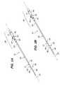
- FIG. 1is an exploded perspective view of a preferred embodiment of an apparatus for sealing a puncture through tissue, in accordance with the present invention.
- FIGS. 2A and 2Bare perspective views of the apparatus of FIG. 1 , showing a balloon thereon in collapsed and expanded states, respectively.
- FIGS. 3A and 3Bare cross-sectional details of a distal portion of the apparatus shown in FIGS. 2A and 2B , respectively.
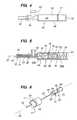
- FIG. 4is a side view of a housing for a hub subassembly of the apparatus of FIG. 1 .
- FIG. 5is a cross-sectional side view of the hub subassembly of FIG. 4 , including a piston and spring therein and connected to inner and outer members of the apparatus.
- FIG. 6is a perspective detail, showing a piston being attached to an inner member and received in a housing to provide the hub subassembly shown in FIGS. 4 and 5 .
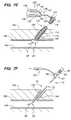
- FIGS. 7A-7Fare cross-sectional views of a percutaneous puncture communicating with a blood vessel showing a method for sealing the puncture, in accordance with the present invention.
- FIG. 8is a cross-sectional detail of an alternative embodiment, showing cooperating stops for preventing over-inflation of the apparatus.
- FIG. 9is a perspective view of a tensioner, in accordance with the present invention.
- FIGS. 1-6show a preferred embodiment of an apparatus 10 for sealing a puncture extending through tissue and/or communicating with a body lumen (not shown).
- the apparatus 10includes an outer member 12 , an inner member 32 slidably coupled to the outer member 12 (best seen in FIGS. 3A , 3 B, and 5 ), a hub subassembly 38 or other mechanism for biasing the inner member 32 relative to the outer member 12 , and a balloon or other expandable member 80 coupled to the inner and outer members 32 , 12 .
- the apparatus 10may include an outer sleeve 90 that may at least partially cover the outer member 12 .
- the outer member 12may be an elongate tubular body including a proximal end 14 , a distal end 16 , and a lumen 18 extending therebetween (shown in FIGS. 3A , 3 B, and 5 ), thereby defining a longitudinal axis 20 .
- the outer member 12may be flexible, semi-rigid, or rigid, e.g., having a uniform or variable flexibility along its length.
- the outer member 12may be formed from a variety of materials providing a desired rigidity, e.g., plastic, such as polyamide, PEEK, nylon, PET, PEBAX, polyethylene, and/or metal, such as stainless steel or a nickel-titanium alloy, fabricated using known processes, e.g., extrusion, roll forming, machining, and the like.
- a lubricious coating(not shown) may be provided on the exterior of the outer member 12 , e.g., Dow 360 silicone fluid.
- the distal end 16is substantially flexible such that the distal end 16 may curve, bend, or otherwise conform substantially to the contour of a puncture and/or body lumen (not shown) into which the distal end 16 is advanced.
- the distal end 16 of the outer member 12may have a size sufficient to be inserted into a relatively small puncture and/or body lumen.
- the distal end 16(and possibly the remainder of the outer member 12 ) may have an outer diameter between about 0.010-0.030 inch (0.25-0.75 mm), and preferably less than about 0.020 inch (0.5 mm).
- An outer sleeve 90may be provided that at least partially surrounds the outer member 12 .
- Exemplary materials for the outer sleeve 90may include plastics, such as polyamide, PEEK, nylon, PET, PEBAX, and polyethylene, metals, such as stainless steel, and nickel titanium, and/or composite materials.
- the outer sleeve 90may include a proximal end 92 connected to the hub subassembly 38 and a tapered distal end 94 that terminates proximal to the distal end 16 of the outer member 12 , as best seen in FIGS. 1 , 2 A, and 2 B.
- the proximal end 90 and the hub subassembly 38may include cooperating connectors, e.g., luer lock connectors (not shown), for detachably connecting the outer sleeve 90 to the hub subassembly 38 .
- the proximal end 92 of the outer sleeve 90may be substantially permanently attached to the hub subassembly 38 , e.g., using an adhesive, mating threads, an interference fit, and the like.
- the outer sleeve 90may enhance a rigidity and/or pushability of the outer member 12 , i.e., may be sufficiently rigid to support the outer member 12 , e.g., to prevent the outer member 12 from buckling or kinking when being advanced into a puncture (not shown).
- a sealing materialis delivered around the outer sleeve 90 into a puncture (e.g., through an introducer sheath, not shown)
- the outer sleeve 90may significantly reduce a volume that must be filled in order to deliver sealing material beyond the introducer sheath (as opposed to delivering the sealing material through the introducer sheath outside the outer member 12 .
- the outer sleeve 90may also minimize a thickness of the hydrogel around the outer sleeve 90 as the introducer sheath is pulled back (e.g., when the tip of the introducer sheath is located over the outer sleeve 90 ). This may also allow the formed hydrogel to break off more easily around the tip of the introducer sheath, because the hydrogel thickness is the thinnest e.g. weakest, preventing disruption of the formed hydrogel within the remainder of the puncture.
- sealing materialssuch as hydrogel polymers
- the outer sleeve 90may be used to exchange one apparatus 10 for another, e.g., in the event that the balloon 80 ruptures or if a different size balloon 80 is desired.
- the outer sleeve 90may include a side port (not shown) on the proximal end 92 for delivering a fluid, e.g., a liquid sealing compound between the outer sleeve 90 and the outer member 12 , as explained further below.
- the inner member 32may be an elongate body including a proximal end 34 (shown in FIGS. 1 and 6 ), and a distal end 36 .
- the inner member 32is slidably received within the lumen 18 of the outer member 12 such that the distal end 36 of the inner member 32 extends beyond the distal end 16 of the outer member 12 .
- the inner member 32is sufficiently small such that the inner member 32 may be received in the lumen 18 of the outer member 12 , yet accommodate fluid being delivered through the lumen 18 , i.e., along an exterior of the inner member 32 .
- the distal end 36 of the inner member 32may extend substantially beyond the distal end 16 of the outer member 12 .
- the distal end 34 of the inner member 32is attached to the balloon 80 , as explained further below.
- the distal end 36 of the inner member 32may terminate in a substantially flexible and/or traumatic distal tip, e.g., a “J” tip and the like (not shown).
- the inner member 32may be a solid or hollow wire, hypotube, catheter, and the like, formed from a variety of materials, e.g., plastic and/or metal, similar to the outer member 12 .
- the inner member 32may be a solid nickel-titanium alloy (“Nitinol”), stainless steel, polymeric and/or composite wire having an outer diameter between about 0.003-0.020 inch (0.075-0.5 mm), and preferably less than about 0.010 inch (0.25 mm).
- the inner member 32may include a lumen (not shown) for receiving a guidewire (not shown) therethrough, e.g., such that the apparatus 10 may be advanced over a guidewire.
- the inner member 32is biased to move distally relative to the outer member 12 , i.e., from a proximal position (such as that shown in FIG. 3B ) to a distal position (such as that shown in FIG. 3A ), e.g., to facilitate collapsing the balloon 80 , as explained further below.
- the hub subassembly 38may be provided for biasing the inner member 32 relative to the outer member 12 .
- the hub subassembly 38includes a housing 40 extending from the proximal end 14 of the outer member 12 and a piston 60 coupled to the proximal end 34 of the inner member 32 .
- the housing 40includes a hollow adaptor end 42 , a side port 44 communicating with an interior 46 of the housing 40 , and a hollow cylinder 48 .
- the cylinder 48may include an outer wall 50 and a proximal end wall 52 , thereby defining a chamber 54 that communicates with the interior 46 of the housing 40 .
- the end wall 52may only partially enclose the chamber 54 or may substantially seal the chamber 54 , as explained further below.
- the adapter end 42 of the housing 40may be attached to the proximal end 14 of the outer member 12 such that the interior 46 of the housing 40 communicates with the lumen 18 of the outer member 12 .
- the adapter end 42may be attached to the proximal end 14 of the outer member 12 using an adhesive, an interference fit, mating threads, and the like, e.g., to substantially permanently attach the housing 40 to the proximal end 14 of the outer member 12 .
- the side port 44may communicate with the lumen 18 via the interior 46 .
- fluid delivered into the side port 44may enter the lumen 18 as well as the chamber 54 of the cylinder 48 via the interior 46 of the housing 40 .
- the side port 44may include a connector, e.g., a luer lock connector, or a nipple (not shown) for connecting tubing or otherwise connecting a source of fluid (not shown) to the side port 44 .
- a syringe 160 filled with inflation mediae.g., saline, carbon dioxide, and the like, may be connected to the side port 44 for manually delivering the inflation media into the lumen 18 .
- a pump or other devicemay be provided for delivering fluid at a desired pressure and/or flow rate.
- the piston 60may be slidably received in the cylinder 48 , thereby dividing the chamber 54 into a proximal chamber 54 a and a distal chamber 54 b .
- the piston 60may include one or more seals 62 for providing a fluid-tight seal between the piston 60 and the side wall 50 of the cylinder 48 , while accommodating the piston 60 sliding within the chamber 54 .
- the piston 60includes a distal plunger section 64 and a proximal seal section 62 attached to the plunger section 64 , as best seen in FIG. 5 .
- the seal section 62may be formed from semi-rigid rubber or other material that may provide a fluid-tight seal with the outer wall 50 of the cylinder 48 .
- the plunger section 64may be formed from plastic, metal, composite, or other material.
- Exemplary devices that may used for the plunger and seal sections 64 , 62include syringe plunger and piston parts sold by Merit Medical, and identified by catalog part number MSS011.
- the seal section 62may be attached to the plunger section 64 , e.g., by a cooperating stem/pocket, an adhesive, an interference fit, mating threads, and the like.
- the plunger section 64 of the piston 50may include a distal surface 66 that is exposed to fluid pressure within the distal chamber 54 b , and consequently to fluid pressure within the interior 46 of the housing 40 and/or within the lumen 18 of the outer member 12 .
- the proximal end 34 of the inner member 32may be coupled to the piston 60 , thereby coupling axial movement of the inner member 32 to axial movement of the piston 60 , as shown in FIG. 5 .
- the distal surface 66 of the piston 50may include an aperture 68 through which the proximal end 34 of the inner member 32 may be received.
- the inner member 12may be secured to the piston 60 .
- a set screw 70may be threaded into a mating pocket 72 that may engage the proximal end 34 of the inner member 32 within the aperture 68 .
- the proximal end 34 of the inner member 32may be attached to the piston 60 , e.g., using an adhesive, sonic welding, crimping, an interference fit, and the like.
- a compression spring or other mechanism 74may be provided in the proximal chamber 54 a of the housing 40 , e.g., for biasing the piston 60 away from the end wall 52 , i.e., towards the adapter end 42 of the housing 40 .
- the spring 74may apply an axial force against a proximal surface 76 of the piston 60 and the end wall 52 of the cylinder 48 .
- the cylinder 48may be open (i.e., may not include end wall 52 initially), and the piston 60 , after being attached to the inner member 32 , may be inserted into the chamber 54 .
- the spring 74may then be inserted into the cylinder 48 , i.e., into the proximal chamber 54 a , until it abuts the proximal surface 76 of the piston 60 .
- An end cap or other end wall 52may then be attached to the cylinder 48 , e.g., using an adhesive, an interference fit, mating threads, and the like, to retain the spring 74 within the proximal chamber 54 a .
- the end wall 52may be an annular shaped cap, although alternatively, the end wall 52 may be a solid walled cap that substantially seals the proximal chamber 54 a.
- the spring constant of the spring 74may be selected to provide a desired biasing force.
- the cylinder 48 and the piston 60may include markers 77 , 78 thereon that may become aligned with one another when the piston 60 moves to an axial location, e.g., the proximal position shown in FIGS. 2B and 7C .
- the axial locationmay correspond to a predetermined pressure within the distal chamber 54 b , e.g., between about twenty and forty pounds per square inch (20-40 psi), and preferably at least about thirty pounds per square inch (30 psi).
- the outer wall 50 of the cylinder 48may include an annular band or other marker 77 and the piston 60 may include another annular band or marker 78 .
- the marker 78may pass behind the marker 77 , thereby indicating that a predetermined pressure has been attained within the distal chamber 54 b ).
- the marker 77may be substantially opaque such that the marker 78 disappears to provide a visual indication.
- the marker 77 on the cylinder 48may be transparent or translucent, and a color of the marker 78 may combine with a color of the marker 77 to provide a visual indication that the predetermined pressure has been reached.
- the predetermined pressuremay correspond to a desired maximum pressure for the balloon 80 , e.g., to ensure that the balloon 80 is expanded to a desired diameter and/or to prevent risk of the balloon 80 rupturing.
- the proximal chamber 46 a of the cylinder 48may be filled with a compressible fluid, e.g., nitrogen, carbon dioxide, or air, that may be pressurized to a predetermined pressure to bias the piston 50 away from the end wall 44 .
- a compressible fluide.g., nitrogen, carbon dioxide, or air
- the pressure of the fluidmay exceed the predetermined pressure, thereby causing the piston 60 to move proximally and compressing the fluid within the proximal chamber 46 a until the pressures within the chambers 46 a , 46 b are substantially equal to one another.
- an extension spring(not shown) may be provided in the distal chamber 54 b that may be coupled to the piston 60 and the cylinder 48 at the end near the side port 44 to bias the piston 60 distally.
- the hub subassembly 38may not include a biasing mechanism, e.g., no spring 74 or compressible fluid.
- movement of the piston 60may be controlled directly by pressure and/or vacuum applied to inflate and/or deflate the balloon 80 , respectively.
- the pressure differential between the piston 60 and the balloon 80may initially cause the piston 60 to slide proximally, thereby applying a proximal tensional load to the inner member 32 while the balloon 80 is expanding.
- the negative pressure differential between the piston 60 and the balloon 80may initially cause the piston 60 to slide distally, thereby applying a distal compressive load to the inner member 32 while the balloon 80 is deflating.
- a desired pressure differentialmay be achieved by using a viscous fluid (i.e., a fluid more viscous than air) and/or by creating a restriction (not shown) within the lumen 18 distal to the side port 44 to delay the pressure from entering or exiting the balloon 80 .
- This pressure differentialmay be particularly important when inflating and/or deflating an everted balloon.
- a constrictionmay be provided within the lumen 18 , e.g., between the side port 44 and the distal end 16 to cause the piston 60 to move before fluid is introduced into the balloon 80 .
- cooperating stops 19 ′, 39 ′may be provided for preventing over-inflation of the balloon 80 (not shown in FIG. 8 ).
- a cylindrical stop 39 ′may be provided on the inner member 32 ′ and an annular stop 19 ′ may be provided that extends into the lumen 18 ′ of the outer member 12 ′ (or alternatively into the interior 46 ′ of the housing 40 ′ distal to the side port 44 ′).
- the inner diameter or cross-section of the stop 19 ′is less than the diameter or cross-section of the stop 39 ′ such that the stops 19 ′, 39 ′ limit relative motion of the inner member 32 ′ and/or seals the lumen 18 ′ from further inflation.
- the inner member 32 ′When the inner member 32 ′ is in a distal position, fluid may flow freely through the lumen 18 ′ around the stop 39 to inflate the balloon 80 , causing the inner member 32 ′ and the stop 39 ′ to move proximally, as explained above.
- the stop 39 ′When the inner member 32 ′ moves to a proximal position (shown in phantom), the stop 39 ′ may engage the stop 19 ′ on the outer member 12 ′.
- the proximal positioncorresponds to a maximum fluid pressure desired for inflating the balloon 80 , thereby preventing the balloon from being over-inflated, which may risk rupturing or otherwise damaging the balloon 80 .
- the balloon 80is carried on the distal end 16 of the outer member 12 .
- the balloon 80may be expandable from a collapsed state (shown in FIGS. 2A and 3A ) to an expanded state (shown in FIGS. 2B and 3B ) when an inflation medium (not shown) is introduced into an interior 82 of the balloon 80 .
- other expandable memberse.g., a mechanically expandable or self-expanding member (not shown) may be provided instead of the balloon 80 .
- the balloon 80may be formed from a flexible, substantially inelastic material, e.g., a nonelastomeric material, such as PET, nylon, polyethylene, polyurethane, PEBAX, and the like, that may provide a substantially noncompliant balloon 80 that may expand to a predetermined size once a minimum pressure is introduced into the interior 82 .
- a flexible, substantially inelastic materiale.g., a nonelastomeric material, such as PET, nylon, polyethylene, polyurethane, PEBAX, and the like, that may provide a substantially noncompliant balloon 80 that may expand to a predetermined size once a minimum pressure is introduced into the interior 82 .
- the size of the balloon 80 in the expanded statemay be fixed.
- the balloon 80may be formed from an elastic material, such that the size of the balloon 80 in the expanded state is dependent upon the pressure or volume of fluid delivered within the interior 82 , as is known in the art.
- the balloon 80includes a proximal end 84 , a distal end 86 , and an expandable intermediate section 88 defining the interior 82 of the balloon 80 .
- the proximal end 84 of the balloon 80may be attached to the distal end 16 of the outer member 12
- the distal end 86 of the balloon 80may be attached to the distal end 36 of the inner member 32 .
- the interior 82 of the balloon 80may communicate with the lumen 18 of the outer member 12 .
- the proximal end 84 of the balloon 80may extend proximally, replacing all or a portion of the outer member 12 (not shown).
- the proximal end 84 of the balloon 80may be laminated or drawn over a stiffer proximal shaft (not shown), or may be supported by an outer sleeve 70 .
- the proximal end 84 of the balloon 80may overlie and be attached to the distal end 16 of the outer member 12 , e.g., using an adhesive, sonic welding, crimping, a compressive sleeve, an interference fit, and the like.
- the distal end 36 of the inner member 32may extend through the interior 82 of the balloon 80 (i.e., through the intermediate section 88 ), and at least partially into the distal end 86 of the balloon 80 , optionally extending an entire length of the distal end 86 of the balloon 80 .
- the distal end 86 of the balloon 80may be attached to the distal end 36 of the inner member 32 , e.g., using an adhesive, sonic welding, crimping, a compressive sleeve, an interference fit, and the like.
- a band of materiale.g., polyamide, may be attached or otherwise provided over the proximal and distal ends 84 , 86 of the balloon 80 to attach the ends 84 , 86 to the outer and inner members 12 , 32 .
- the distal end 86 of the balloon 80may extend beyond the distal end 36 of the inner member 32 , e.g., to provide a floppy or otherwise substantially atraumatic tip for the apparatus 10 .
- the distal end 86 of the balloon 80may have a length of at least about fifty millimeters (50 mm), and the distal end 36 of the inner member 32 may only extend about twenty millimeters (20 mm) or less into the distal end 86 of the balloon 80 .
- the distal end 36 of the inner member 32may extend beyond the distal end 86 of the balloon 80 , and may terminate in a substantially atraumatic tip (not shown).
- the balloon 80may conform substantially to the diameter of the outer member 12 .
- the proximal and distal ends 84 , 86 of the balloon 80 and the distance between the distal ends 16 , 36 of the outer and inner members 12 , 32are such that the balloon 80 is under slight axial tension in the collapsed state, thereby minimizing risk of the balloon 80 expanding, kinking, otherwise increasing in cross-section and/or catching on anything contacted by the balloon 80 .
- the balloon 80is expanded to the expanded state, shown in FIGS. 2B and 3B , by introducing an inflation medium (not shown) into the lumen 18 of the outer member 12 , and consequently into the interior 82 of the balloon 80 .
- an inflation mediumis introduced into the lumen 18
- fluidinitially enters the interior 46 of the housing 40 (not shown, see FIGS. 4 and 5 ), and consequently into the distal chamber 54 b of the cylinder 48 (also not shown, see FIGS. 4 and 5 ).
- the piston 60may move proximally within the cylinder 48 , thereby pulling the inner member 32 proximally.
- the intermediate section 88 of the balloon 80may have a length L C
- the intermediate section 88may have a length L E that is substantially shorter than L C
- the balloon 80may have a diameter between about four and ten millimeters (4-10 mm), and a length L E between about two and ten millimeters (2-10 mm).
- the balloonmay have a diameter of about six millimeters (6 mm) at thirty pounds per square inch (30 psi) internal pressure and a length L E between about four and eight millimeters (4-8 mm).
- the balloon 80at least partially everts in the expanded state, i.e., the length L E of the balloon 80 may be substantially smaller than the diameter.
- the proximal and distal ends 84 , 86 of the balloon 80may become sufficiently close to one another that they at least partially enter the interior 82 of the balloon 80 , as shown in FIG. 3B , thereby defining a toroidal shape.
- This everted configurationmay facilitate creating homeostasis within a puncture in a wall of a body lumen (not shown) while allowing at least some fluid flow to continue along the body lumen, as explained further below.
- the cross-section of the distal chamber 54 b of the cylinder 48may be substantially larger than a cross-section of the lumen 18 of the outer member 12 .
- the cylinder 48may have an inner diameter between about 0.050-0.100 inch (1.25-2.5 mm), while the lumen 18 may have a diameter between about 0.010-0.020 inch (0.25-0.50 mm).
- a cross-sectional area of the distal surface 66 of the piston 60may be substantially greater than a cross-sectional area of the lumen 18 .
- a fluidWhen a fluid is introduced into the side port 44 of the hub subassembly 38 under pressure, the pressure may impose a proximal force on the distal surface 66 of the piston 60 . Because of the relatively large area of the distal chamber 54 b , fluid may flow easily into the distal chamber 54 b before flowing down the lumen 18 into the interior of the balloon 80 . Thus, as fluid is introduced into the side port 44 , a proximal force may be applied to the piston 60 before or as the balloon begins to expand, thereby shortening the balloon 80 before or as it expands towards the expanded state.
- the fluid from the distal chamber 54 b of the cylinder 48may be removed before fluid is drawn up the lumen 18 and the balloon 80 begins to collapse.
- the resulting vacuummay pull the piston 60 distally, causing the balloon 80 to elongate towards its collapsed length L C before or as the balloon collapses towards the collapsed state.
- This featuremay be particularly useful for ensuring that the balloon 80 is collapsed to as small a profile as possible when the balloon 80 is collapsed from the expanded state to the collapsed state, as explained further below.
- the apparatus 10may include other components, e.g., to provide a kit for performing a procedure on a patient.
- an introducer sheath 110may be provided that includes a proximal end 112 , a distal end 114 , and a lumen 116 extending therebetween.
- the introducer sheath 110may include a tapered distal tip 117 , e.g., for facilitating advancing the introducer sheath 110 through a puncture, as is well known to those skilled in the art.
- the introducer sheath 110may include a side port 120 on the proximal end 114 communicating with the lumen 116 and/or may include one or more seals (not shown), e.g., to prevent substantial proximal flow of fluid through the lumen 116 , as is known in the art.
- a source of sealing compound 130may be connectable to the side port 120 , e.g., for delivering a sealing compound into the lumen 116 of the introducer sheath 110 .
- a dual syringe assembly 130may be provided that includes two components of a sealing compound.
- a prepolymeris provided in each syringe 132 of the syringe assembly 130 .
- a “Y” fitting 140may be provided that includes proximal sections 142 that communicate with a single distal section 144 .
- the proximal and distal sections 142 , 144may include connectors, e.g., luer lock connectors and the like (not shown), for connecting with outlets 136 of the syringes 132 and with the side port 120 of the introducer sheath 110 .
- the “Y” fitting 140may be connectable to outlets 136 of the syringes 132 such that the components ejected out of the syringes 132 may mix before being injected into the side port 120 of the introducer sheath 110 .
- the “Y” fitting 140may include one or more components, e.g., separate lengths of tubing and the like (not shown), as will be appreciated by those skilled in the art.
- the componentsare prepolymer that mix to create a hydrogel, as explained further below. Additional information on hydrogels and systems for injecting them are disclosed in U.S. Pat. Nos. 6,152,943, 6,165,201, 6,179,862, 6,514,534, and 6,379,373, and in co-pending application Ser. Nos. 09/776,120 filed Feb. 2, 2001, 10/010,715 filed Nov. 9, 2001, and 10/068,807 filed Feb. 5, 2002. The disclosures of these references and any others cited therein are expressly incorporated by reference herein.
- the kitmay include a syringe 160 (as shown in FIGS. 7C and 7F ) or other device for delivering inflation medium into the side port 44 of the apparatus 10 , as explained above.
- the kitmay also include a stylet or obturator (not shown) that may be inserted into the lumen 116 of the introducer sheath 110 , e.g., to facilitate percutaneously inserting the introducer sheath 110 through tissue, as is known to those skilled in the art.
- one or more guidewiresmay also be provided.
- the passageis a percutaneous puncture 190 extending from a patient's skin 192 to a blood vessel or other body lumen 194 .
- the vessel 194may be a peripheral artery, e.g., a femoral artery, a carotid artery, and the like.
- an introducer sheath 110may be placed within the puncture 190 such that the distal end 114 is disposed within the vessel 192 .
- a stylet having a sharpened distal tip(not shown) may be inserted through the lumen 116 of the introducer sheath 110 such that the sharpened distal tip extends beyond the distal end 116 of the introducer sheath 110 .
- the introducer sheath 110 and styletmay then be inserted directly through the patient's skin 192 until the distal end 114 is disposed within the vessel 194 .
- the introducer sheath 112may be advanced over a guidewire previously inserted through the puncture 190 into the vessel 194 , using known procedures, such as those described in the Background above.
- One or more instrumentsmay be advanced through the introducer sheath 110 and into the vessel 194 , e.g., to perform a diagnostic and/or therapeutic procedure within the patient's body.
- the one or more instrumentsmay include catheters, e.g., balloon catheters, stent delivery catheters, imaging catheters, and the like, guidewires, and/or other devices.
- catheterse.g., balloon catheters, stent delivery catheters, imaging catheters, and the like, guidewires, and/or other devices.
- any instrumentsmay be removed and the puncture 190 may be sealed using an apparatus, such that shown in FIGS. 1-6 and described above.
- the apparatus 10may be inserted through the lumen 116 of the introducer sheath 110 until the balloon 80 is disposed within the vessel 194 .
- the apparatus 10may include one or more markers, e.g., radiopaque markers (not shown), to facilitate monitoring insertion of the apparatus 10 using external imaging, e.g., fluoroscopy, ultrasound, magnetic resonance imaging (“MRI”), and the like.
- one or more visual markersmay be provided, e.g., on the proximal end 14 of the outer member 12 (or the outer sleeve 90 if provided around the outer member 12 ).
- the markersmay include one or more colored bands at predetermined locations along a length of the outer member 12 relative to the balloon 80 .
- a distance between a band on the proximal end 14 of the outer member 12may correspond to a length of the introducer sheath 110 , thereby providing a visual indication when the apparatus 10 has been advanced sufficiently to expose the balloon 80 beyond the distal end 114 of the introducer sheath.
- the balloon 80may be expanded to the expanded state, e.g., by introducing fluid into the side port 44 from a syringe 160 through the outer member 12 and into the balloon 80 .
- the inner member 32may be moved proximally relative to the outer member 12 , thereby causing the balloon 80 to shorten as it expands.
- the fluidis introduced until the piston 60 moves proximally and the markers 77 , 78 are aligned with one another, as shown in FIG. 7C . This may inform the user that a desired pressure has been reached and/or that the balloon 80 has been expanded to a desired size.
- the apparatus 10includes a detachable outer sleeve 90
- the rest of the apparatus 10i.e., the outer and inner members 12 , 32 , balloon 80 , and hub subassembly 38
- the outer sleeve 90may be disconnected, and the apparatus 10 replaced with another one having an intact balloon (not shown).
- the apparatus 10may be replaced with one having a larger or smaller balloon.
- the apparatus 10may be partially withdrawn from the puncture 190 with the balloon 80 in the expanded state, i.e., until the balloon 80 engages the puncture 190 .
- the balloon 80substantially seals the puncture 190 , i.e., substantially isolating the puncture 190 from the interior of the vessel 194 .
- the apparatus 10may provide temporary homeostasis, e.g., preventing blood from passing through the puncture 190 .
- the apparatus 10may be used to provide homeostasis in emergency situations in order to minimize loss of blood until a puncture victim may be treated.
- the balloon 80at least partially everts in the expanded state, as described above.
- This everted configurationmay be particularly for providing homeostasis, while still allowing blood flow to continue along the vessel 194 .
- the diameter of the balloon 80may be substantially greater than its length in the expanded state.
- a tensioner 150may be provided that may apply a proximal force to the apparatus 10 to maintain the balloon 80 substantially against the puncture 190 .
- the tensioner 150may include a base portion 152 , a biasing support 154 , and a saddle 156 .
- the base portion 152may be substantially flat or shaped to conform to the patient's anatomy, e.g., to follow the contour or otherwise lie on a patient's leg (not shown) or other skin 192 overlying the puncture 190 .
- the saddle 156may include a wire or plate including a slot 158 or other mechanism for grasping or otherwise engaging the apparatus 10 .
- the slot 158may have a width large enough to receive the outer member 12 or the outer sleeve 90 therein but smaller than the hub subassembly 38 .
- the biasing support 154includes ends connected to the base support 152 and the saddle 156 and may be biased to provide a predetermined spacing between the base support 152 and the saddle 156 .
- the biasing support 154is adjustable to allow the spacing between the base support 152 and saddle 156 to be adjusted based upon the particular anatomy encountered during a procedure.
- the tensioner 150may simply be a wire frame (not shown) that is bent or otherwise shaped to provide the base support 152 , biasing support 154 , and saddle 156 . It will be appreciated that other structures, including two or more separate parts may be assembled to provide a tensioner in accordance with the present invention.
- the tensionermay be made from a single structure formed, molded, or otherwise created in a desired shape.
- the base portion 152may be placed in contact with the patient, e.g., set on the patient's skin 192 adjacent to the puncture 190 .
- the apparatus 10may be received in the saddle 156 , e.g., by inserting the outer member 12 into the slot 158 .
- the apparatus 10may then be released, and the tensioner 150 may pull the apparatus 10 proximally with sufficient tension to maintain the balloon 80 in contact with the wall 196 of the vessel 194 .
- the biasing support 154may be reshaped to increase or decrease the distance between the saddle 156 and the base support 152 and/or to increase or decrease the tension as necessary for the anatomy encountered.
- the tension imposed by the tensioner 150may apply a desired tensile force to the balloon to maintain homeostasis while preventing the balloon 80 from being pulled into the puncture 190 and/or preventing the wall 196 of the vessel 194 from excessive tenting.
- the saddle 156 of the tensioner 150may be engaged in one of a plurality of mating slots (not shown) provided in the outer wall 50 of the cylinder 48 to provide a desired tension on the balloon 80 .
- the slotsmay allow a desired tension independent of a patient profile (e.g., obese or thin) where a distance of the vessel 194 from the skin 192 varies from shallow to deep.
- a sealing compound 146may be delivered into the puncture.
- the sealing compoundis a liquid or other flowable material that may be injected into the puncture 190 . Because of the homeostasis provided by the balloon 80 , the sealing compound 146 may be delivered without substantial concern that the sealing compound 146 may leak into the vessel 194 .
- the sealing compoundincludes multiple component prepolymers that create a hydrogel when mixed together, as described above.
- a sealing compoundmay be particularly useful, because it may be substantially harmless to the patient even if it somehow leaks into the vessel 194 .
- hydrogel prepolymersmay not promote homeostasis within a blood vessel. In fact, such prepolymers, if leaked into a vessel, may simply dilute and flow away, where they may be metabolized naturally without substantial risk of creating thrombus.
- a two-part sealing compoundis shown contained within a dual syringe assembly 130 .
- the prepolymers or other components in the syringes 132may be mixed or otherwise prepared using known procedures.
- the plungers 134 of the syringes 132may be linked such that they may be depressed substantially simultaneously, thereby delivering the prepolymers simultaneously.
- the prepolymersmay mix in the “Y” fitting 140 into a liquid sealing compound 146 , and then be delivered into the side port 120 of the introducer sheath 110 .
- an auto injector deviceincluding a spring, motor, pneumatic pressure, and the like (not shown) may be provided for delivering the prepolymers at a desired substantially continuous rate. Such a device may prevent unintended pauses during delivery, which may cause the “Y” fitting 140 or other passages through which the sealing compound passes from becoming obstructed.
- the liquid sealing compound 146may be injected through the lumen 116 of the introducer sheath 110 out the distal end 114 into the puncture 190 .
- the introducer sheath 110may remain stationary as the sealing compound 146 is delivered, thereby allowing the sealing compound to flow into the puncture 190 around the introducer sheath 110 .
- a sealing element(not shown) may be provided on the exterior of the introducer sheath 110 for sealing the puncture 190 at or near the surface of the skin 192 .
- a balloon or other expandable membermay be provided on or near the proximal end 112 of the introducer sheath 110 .
- the expandable membermay be expanded to substantially seal the proximal end of the puncture 190 , thereby preventing substantial amounts of sealing compound leaking out of the puncture.
- a “C” shaped clip or other elementmay be attached around the introducer sheath 110 , e.g., at the skin 192 for substantially sealing the puncture 190 .
- the introducer sheath 110may be withdrawn proximally from the puncture 190 as the sealing compound 146 is delivered, thereby filling the puncture tract with the sealing compound 146 , as shown in FIG. 7F .
- an annular ridge, bump, or other elementmay be provided on an exterior of the proximal end 14 of the outer member 12 (or the outer sleeve 90 ) to prevent the sealing compound from being pulled proximally along with the introducer sheath 110 .
- the lumen 116 of the introducer sheathmay be coated with a lubricious material, e.g., silicone to facilitate the introducer sheath 110 sliding over the sealing compound 146 .
- a balloon, braid structure, and/or other expandable membermay be provided on the distal end 114 of introducer sheath 110 .
- This expandable membermay be expanded and deflated (one or more times) to dilate or otherwise enlarged the puncture 194 tract to accommodate more sealing compound 146 being delivered into the puncture 190 .
- the expandable membermay remain expanded while the introducer sheath 110 is at least partially withdrawn from the puncture 190 to enlarge the puncture along its length.
- a plurality of spaced-apart balloons or other expandable membersmay be provided along the introducer sheath 110 for isolating segments of the puncture 190 .
- the introducer sheath 110may include one or more outlets (also not shown) disposed between the balloons that communicate with the lumen 116 of the introducer sheath 110 .
- sealing compoundmay be delivered into each of the individual isolated segments of the puncture 190 , which may ensure sealing along the length of the puncture 190 .
- a port(not shown) may be provided in the outer sleeve 90 (not shown in FIGS. 7E and 7F ), and the introducer sheath 110 may be removed before the sealing compound is delivered.
- the sealing compoundmay be delivered into the side port of the outer sleeve 90 , through the lumen of the outer sleeve 90 along the outer member 12 , and into the puncture 19 .
- This alternativemay reduce a volume of sealing compound necessary to fill the puncture 190 as compared to filling the volume of the lumen of a relatively large bore introducer sheath 110 , as will be appreciated by those skilled in the art.
- other devicesmay be used for delivering sealing material into the puncture 190 .
- other apparatus for delivering liquid sealing compoundsincluding single or multiple lumens (not shown), may be advanced over the apparatus 10 , e.g., through the introducer sheath 110 .
- the introducer sheath 110may be removed, before such delivery apparatus are advanced over the apparatus 10 into the puncture 190 .
- solid plugssuch as those disclosed in U.S. Pat. No. 5,108,421 may be advanced into the puncture 190 adjacent or around the apparatus 10 .
- the balloon 80may provide homeostasis and/or prevent a plug or other solid or liquid sealing compound from entering the vessel 194 as it is introduced into the puncture 190 .
- the sealing compound 146may given sufficient time to at least partially (or fully) solidify, e.g., between about five and one hundred eighty (5-180) seconds.
- the balloon 80may then be collapsed to the collapsed state and then withdrawn from the puncture 190 .
- the syringe 160 or other devicemay be used to evacuate fluid via the side port 44 to collapse the balloon 80 .
- fluidmay be drawn initially from the cylinder 48 , thereby causing the piston 60 to advance distally and push the inner member 32 distally to elongate the balloon 80 .
- the piston 60 and inner member 32may subject the balloon 80 to axial tension, thereby minimizing its profile in the collapsed state, which may facilitate removing the balloon 80 through the puncture 190 without substantially disturbing the surrounding sealing compound 146 .
- a lubricious coatingmay be provided on the exterior of the outer member 12 , e.g., Dow 360 silicone fluid. Such a coating may prevent the sealing compound 146 from sticking to or otherwise pulling on the outer member 12 (or the outer sleeve 90 ) as the apparatus 10 is withdrawn.
- external pressuremay be applied, e.g., by pressing manually against the skin 192 overlying the vessel 194 , e.g., to at least partially suppress flow through the vessel 194 .
- the balloon 80(and the rest of the apparatus 10 ) may be removed, and the external pressure may be maintained for sufficient time to allow the sealing compound 146 to solidify further, e.g., between about ten and one hundred eighty (10-180) seconds.
- the sealing compoundmay expand, e.g., due to its elasticity and/or due to further solidification, thereby substantially sealing the relatively small tract remaining upon removing the apparatus 10 .
- the tensioner 150may be used to maintain tension on the balloon 80 for a prolonged period of time with the balloon 80 providing temporary homeostasis to allow the hydrogel to cure fully in the puncture 190 before removing the apparatus 10 .
Landscapes
- Health & Medical Sciences (AREA)
- Life Sciences & Earth Sciences (AREA)
- Surgery (AREA)
- Heart & Thoracic Surgery (AREA)
- Public Health (AREA)
- Animal Behavior & Ethology (AREA)
- Biomedical Technology (AREA)
- Veterinary Medicine (AREA)
- General Health & Medical Sciences (AREA)
- Engineering & Computer Science (AREA)
- Molecular Biology (AREA)
- Medical Informatics (AREA)
- Nuclear Medicine, Radiotherapy & Molecular Imaging (AREA)
- Cardiology (AREA)
- Anesthesiology (AREA)
- Biophysics (AREA)
- Pulmonology (AREA)
- Child & Adolescent Psychology (AREA)
- Hematology (AREA)
- Surgical Instruments (AREA)
- Media Introduction/Drainage Providing Device (AREA)
- Prostheses (AREA)
- Vending Machines For Individual Products (AREA)
- Ultra Sonic Daignosis Equipment (AREA)
Abstract
Description
Claims (25)
Priority Applications (1)
| Application Number | Priority Date | Filing Date | Title |
|---|---|---|---|
| US11/929,728US8128654B2 (en) | 2003-06-04 | 2007-10-30 | Apparatus and methods for sealing a vascular puncture |
Applications Claiming Priority (2)
| Application Number | Priority Date | Filing Date | Title |
|---|---|---|---|
| US10/454,362US7331979B2 (en) | 2003-06-04 | 2003-06-04 | Apparatus and methods for sealing a vascular puncture |
| US11/929,728US8128654B2 (en) | 2003-06-04 | 2007-10-30 | Apparatus and methods for sealing a vascular puncture |
Related Parent Applications (1)
| Application Number | Title | Priority Date | Filing Date |
|---|---|---|---|
| US10/454,362ContinuationUS7331979B2 (en) | 2003-06-04 | 2003-06-04 | Apparatus and methods for sealing a vascular puncture |
Publications (2)
| Publication Number | Publication Date |
|---|---|
| US20080058862A1 US20080058862A1 (en) | 2008-03-06 |
| US8128654B2true US8128654B2 (en) | 2012-03-06 |
Family
ID=33489718
Family Applications (5)
| Application Number | Title | Priority Date | Filing Date |
|---|---|---|---|
| US10/454,362Active2026-07-28US7331979B2 (en) | 2003-06-04 | 2003-06-04 | Apparatus and methods for sealing a vascular puncture |
| US10/806,934Expired - LifetimeUS7553319B2 (en) | 2003-06-04 | 2004-03-22 | Auto-injector apparatus and methods for sealing a vascular puncture |
| US10/806,927Expired - Fee RelatedUS7316704B2 (en) | 2003-06-04 | 2004-03-22 | Occlusion member and tensioner apparatus and methods of their use for sealing a vascular puncture |
| US11/929,762Expired - Fee RelatedUS7985240B2 (en) | 2003-06-04 | 2007-10-30 | Occlusion member and tensioner apparatus and methods of their use for sealing a vascular puncture |
| US11/929,728Expired - Fee RelatedUS8128654B2 (en) | 2003-06-04 | 2007-10-30 | Apparatus and methods for sealing a vascular puncture |
Family Applications Before (4)
| Application Number | Title | Priority Date | Filing Date |
|---|---|---|---|
| US10/454,362Active2026-07-28US7331979B2 (en) | 2003-06-04 | 2003-06-04 | Apparatus and methods for sealing a vascular puncture |
| US10/806,934Expired - LifetimeUS7553319B2 (en) | 2003-06-04 | 2004-03-22 | Auto-injector apparatus and methods for sealing a vascular puncture |
| US10/806,927Expired - Fee RelatedUS7316704B2 (en) | 2003-06-04 | 2004-03-22 | Occlusion member and tensioner apparatus and methods of their use for sealing a vascular puncture |
| US11/929,762Expired - Fee RelatedUS7985240B2 (en) | 2003-06-04 | 2007-10-30 | Occlusion member and tensioner apparatus and methods of their use for sealing a vascular puncture |
Country Status (7)
| Country | Link |
|---|---|
| US (5) | US7331979B2 (en) |
| EP (1) | EP1631197B1 (en) |
| JP (1) | JP4440259B2 (en) |
| AT (1) | ATE355019T1 (en) |
| CA (1) | CA2527333C (en) |
| DE (1) | DE602004005037T2 (en) |
| WO (1) | WO2005000126A2 (en) |
Cited By (5)
| Publication number | Priority date | Publication date | Assignee | Title |
|---|---|---|---|---|
| US20120290001A1 (en)* | 2011-05-11 | 2012-11-15 | Accessclosure, Inc. | Apparatus and methods for sealing a vascular puncture |
| US8845683B2 (en) | 2008-08-26 | 2014-09-30 | St. Jude Medical, Inc. | Method and system for sealing percutaneous punctures |
| US9107646B2 (en)* | 2013-03-11 | 2015-08-18 | St. Jude Medical Puerto Rico Llc | Active securement detachable sealing tip for extra-vascular closure device and methods |
| US9713462B2 (en) | 2008-11-12 | 2017-07-25 | Accessclosure, Inc. | Apparatus and methods for sealing a vascular puncture |
| US10213191B2 (en) | 2006-09-13 | 2019-02-26 | Accessclosure, Inc. | Apparatus and methods for sealing a vascular puncture |
Families Citing this family (231)
| Publication number | Priority date | Publication date | Assignee | Title |
|---|---|---|---|---|
| US20020095164A1 (en)* | 1997-06-26 | 2002-07-18 | Andreas Bernard H. | Device and method for suturing tissue |
| US7335220B2 (en)* | 2004-11-05 | 2008-02-26 | Access Closure, Inc. | Apparatus and methods for sealing a vascular puncture |
| US6964668B2 (en) | 1999-03-04 | 2005-11-15 | Abbott Laboratories | Articulating suturing device and method |
| US8137364B2 (en)* | 2003-09-11 | 2012-03-20 | Abbott Laboratories | Articulating suturing device and method |
| US7842048B2 (en) | 2006-08-18 | 2010-11-30 | Abbott Laboratories | Articulating suture device and method |
| US7235087B2 (en)* | 1999-03-04 | 2007-06-26 | Abbott Park | Articulating suturing device and method |
| US7001400B1 (en) | 1999-03-04 | 2006-02-21 | Abbott Laboratories | Articulating suturing device and method |
| US20040092964A1 (en)* | 1999-03-04 | 2004-05-13 | Modesitt D. Bruce | Articulating suturing device and method |
| US6488689B1 (en) | 1999-05-20 | 2002-12-03 | Aaron V. Kaplan | Methods and apparatus for transpericardial left atrial appendage closure |
| US8758400B2 (en) | 2000-01-05 | 2014-06-24 | Integrated Vascular Systems, Inc. | Closure system and methods of use |
| US6391048B1 (en) | 2000-01-05 | 2002-05-21 | Integrated Vascular Systems, Inc. | Integrated vascular device with puncture site closure component and sealant and methods of use |
| US7842068B2 (en)* | 2000-12-07 | 2010-11-30 | Integrated Vascular Systems, Inc. | Apparatus and methods for providing tactile feedback while delivering a closure device |
| US6461364B1 (en) | 2000-01-05 | 2002-10-08 | Integrated Vascular Systems, Inc. | Vascular sheath with bioabsorbable puncture site closure apparatus and methods of use |
| US9579091B2 (en) | 2000-01-05 | 2017-02-28 | Integrated Vascular Systems, Inc. | Closure system and methods of use |
| DE60144328D1 (en)* | 2000-09-08 | 2011-05-12 | Abbott Vascular Inc | Surgical clamp |
| US6626918B1 (en) | 2000-10-06 | 2003-09-30 | Medical Technology Group | Apparatus and methods for positioning a vascular sheath |
| US8690910B2 (en) | 2000-12-07 | 2014-04-08 | Integrated Vascular Systems, Inc. | Closure device and methods for making and using them |
| US7806904B2 (en)* | 2000-12-07 | 2010-10-05 | Integrated Vascular Systems, Inc. | Closure device |
| US6623510B2 (en) | 2000-12-07 | 2003-09-23 | Integrated Vascular Systems, Inc. | Closure device and methods for making and using them |
| US6695867B2 (en) | 2002-02-21 | 2004-02-24 | Integrated Vascular Systems, Inc. | Plunger apparatus and methods for delivering a closure device |
| US7905900B2 (en)* | 2003-01-30 | 2011-03-15 | Integrated Vascular Systems, Inc. | Clip applier and methods of use |
| US7211101B2 (en) | 2000-12-07 | 2007-05-01 | Abbott Vascular Devices | Methods for manufacturing a clip and clip |
| US7029480B2 (en)* | 2001-01-24 | 2006-04-18 | Abott Laboratories | Device and method for suturing of internal puncture sites |
| US6743195B2 (en)* | 2001-03-14 | 2004-06-01 | Cardiodex | Balloon method and apparatus for vascular closure following arterial catheterization |
| US8992567B1 (en) | 2001-04-24 | 2015-03-31 | Cardiovascular Technologies Inc. | Compressible, deformable, or deflectable tissue closure devices and method of manufacture |
| US8961541B2 (en) | 2007-12-03 | 2015-02-24 | Cardio Vascular Technologies Inc. | Vascular closure devices, systems, and methods of use |
| US20080109030A1 (en) | 2001-04-24 | 2008-05-08 | Houser Russell A | Arteriotomy closure devices and techniques |
| IES20010547A2 (en)* | 2001-06-07 | 2002-12-11 | Christy Cummins | Surgical Staple |
| US7192436B2 (en)* | 2001-11-08 | 2007-03-20 | Sub-Q, Inc. | Pledget-handling system and method for delivering hemostasis promoting material to a blood vessel puncture site by fluid pressure |
| IES20030424A2 (en)* | 2002-06-04 | 2003-12-10 | Robert Stevenson | Blood vessel closure clip and delivery device |
| AU2003297665A1 (en)* | 2002-12-06 | 2004-06-30 | Fast Country, Inc. | Systems and methods for providing interactive guest resources |
| US7160309B2 (en) | 2002-12-31 | 2007-01-09 | Laveille Kao Voss | Systems for anchoring a medical device in a body lumen |
| US8202293B2 (en) | 2003-01-30 | 2012-06-19 | Integrated Vascular Systems, Inc. | Clip applier and methods of use |
| US8821534B2 (en) | 2010-12-06 | 2014-09-02 | Integrated Vascular Systems, Inc. | Clip applier having improved hemostasis and methods of use |
| US8905937B2 (en) | 2009-02-26 | 2014-12-09 | Integrated Vascular Systems, Inc. | Methods and apparatus for locating a surface of a body lumen |
| US8398656B2 (en) | 2003-01-30 | 2013-03-19 | Integrated Vascular Systems, Inc. | Clip applier and methods of use |
| US7857828B2 (en)* | 2003-01-30 | 2010-12-28 | Integrated Vascular Systems, Inc. | Clip applier and methods of use |
| US8758398B2 (en) | 2006-09-08 | 2014-06-24 | Integrated Vascular Systems, Inc. | Apparatus and method for delivering a closure element |
| US7115127B2 (en) | 2003-02-04 | 2006-10-03 | Cardiodex, Ltd. | Methods and apparatus for hemostasis following arterial catheterization |
| US7223266B2 (en) | 2003-02-04 | 2007-05-29 | Cardiodex Ltd. | Methods and apparatus for hemostasis following arterial catheterization |
| US9289195B2 (en) | 2003-06-04 | 2016-03-22 | Access Closure, Inc. | Auto-retraction apparatus and methods for sealing a vascular puncture |
| US7331979B2 (en) | 2003-06-04 | 2008-02-19 | Access Closure, Inc. | Apparatus and methods for sealing a vascular puncture |
| US7462188B2 (en)* | 2003-09-26 | 2008-12-09 | Abbott Laboratories | Device and method for suturing intracardiac defects |
| US7846168B2 (en)* | 2003-10-09 | 2010-12-07 | Sentreheart, Inc. | Apparatus and method for the ligation of tissue |
| US7449024B2 (en) | 2003-12-23 | 2008-11-11 | Abbott Laboratories | Suturing device with split arm and method of suturing tissue |
| JP4955534B2 (en) | 2004-03-22 | 2012-06-20 | アクセスクロージャー,インク. | Device for sealing vascular perforations |
| US20050267520A1 (en) | 2004-05-12 | 2005-12-01 | Modesitt D B | Access and closure device and method |
| IES20040368A2 (en) | 2004-05-25 | 2005-11-30 | James E Coleman | Surgical stapler |
| US8636694B2 (en)* | 2004-06-14 | 2014-01-28 | Medtronic, Inc. | Modular medical injection system |
| US7678133B2 (en)* | 2004-07-10 | 2010-03-16 | Arstasis, Inc. | Biological tissue closure device and method |
| US7918800B1 (en)* | 2004-10-08 | 2011-04-05 | Endovascular Technologies, Inc. | Aneurysm sensing devices and delivery systems |
| US8262693B2 (en)* | 2004-11-05 | 2012-09-11 | Accessclosure, Inc. | Apparatus and methods for sealing a vascular puncture |
| EP1814478A4 (en) | 2004-11-22 | 2011-05-18 | Cardiodex Ltd | Techniques for heat-treating varicose veins |
| BRPI0606694B8 (en)* | 2005-01-13 | 2019-10-15 | Avox Systems Inc | cartridge for use with a distributor |
| US7918865B2 (en)* | 2005-04-07 | 2011-04-05 | Sentreheart, Inc. | Apparatus and method for the ligation of tissue |
| US7806856B2 (en)* | 2005-04-22 | 2010-10-05 | Accessclosure, Inc. | Apparatus and method for temporary hemostasis |
| CA2904939C (en) | 2005-04-22 | 2018-01-16 | Celso J. Bagaoisan | Apparatus and methods for sealing a puncture in tissue |
| US8002742B2 (en)* | 2005-04-22 | 2011-08-23 | Accessclosure, Inc. | Apparatus and methods for sealing a puncture in tissue |
| CN103190942A (en) | 2005-05-12 | 2013-07-10 | 阿尔斯塔西斯公司 | Access and closure device and method |
| US8926633B2 (en) | 2005-06-24 | 2015-01-06 | Abbott Laboratories | Apparatus and method for delivering a closure element |
| US8313497B2 (en) | 2005-07-01 | 2012-11-20 | Abbott Laboratories | Clip applier and methods of use |
| US20080312686A1 (en)* | 2005-07-01 | 2008-12-18 | Abbott Laboratories | Antimicrobial closure element and closure element applier |
| US7947010B2 (en)* | 2005-07-08 | 2011-05-24 | Depuy Products, Inc. | Composition and system for wound decontamination |
| US8267947B2 (en) | 2005-08-08 | 2012-09-18 | Abbott Laboratories | Vascular suturing device |
| US7883517B2 (en) | 2005-08-08 | 2011-02-08 | Abbott Laboratories | Vascular suturing device |
| US8083754B2 (en) | 2005-08-08 | 2011-12-27 | Abbott Laboratories | Vascular suturing device with needle capture |
| US20070060895A1 (en)* | 2005-08-24 | 2007-03-15 | Sibbitt Wilmer L Jr | Vascular closure methods and apparatuses |
| US8920442B2 (en) | 2005-08-24 | 2014-12-30 | Abbott Vascular Inc. | Vascular opening edge eversion methods and apparatuses |
| US8758397B2 (en)* | 2005-08-24 | 2014-06-24 | Abbott Vascular Inc. | Vascular closure methods and apparatuses |
| US9456811B2 (en) | 2005-08-24 | 2016-10-04 | Abbott Vascular Inc. | Vascular closure methods and apparatuses |
| US7780714B2 (en)* | 2005-11-01 | 2010-08-24 | Cordis Corporation | Implant delivery apparatus |
| US7607557B2 (en)* | 2005-11-04 | 2009-10-27 | Ethicon Endo-Surgery, Inc. | Surgical stapling instruments structured for pump-assisted delivery of medical agents |
| US9179897B2 (en) | 2005-12-13 | 2015-11-10 | Cardiva Medical, Inc. | Vascular closure devices and methods providing hemostatic enhancement |
| US7691127B2 (en)* | 2005-12-13 | 2010-04-06 | Cardiva Medical, Inc. | Drug eluting vascular closure devices and methods |
| US8317822B2 (en)* | 2005-12-22 | 2012-11-27 | Ethicon, Inc. | Systems and methods for closing a vessel wound |
| US8382794B2 (en)* | 2006-01-04 | 2013-02-26 | St. Jude Medical Puerto Rico Llc | Balloon insertion apparatus and method of sealing a tissue puncture |
| US7708722B2 (en) | 2006-01-10 | 2010-05-04 | Stealth Therapeutics, Inc. | Stabilized implantable vascular access port |
| US7682371B2 (en)* | 2006-01-25 | 2010-03-23 | Medtronic Vascular, Inc. | Device with actuatable fluid-column occluder for prevention of embolization |
| WO2007087460A2 (en)* | 2006-01-30 | 2007-08-02 | Glenn Bradley J | Bone supported vascular access port |
| US8795709B2 (en) | 2006-03-29 | 2014-08-05 | Incept Llc | Superabsorbent, freeze dried hydrogels for medical applications |
| US9138563B2 (en)* | 2006-03-31 | 2015-09-22 | Stealth Therapeutics, Inc. | Subcutaneous catheter retainer |
| US20070270879A1 (en)* | 2006-04-19 | 2007-11-22 | Depuy Spine, Inc. | Sacroiliac joint fusion alignment guide |
| US8808310B2 (en) | 2006-04-20 | 2014-08-19 | Integrated Vascular Systems, Inc. | Resettable clip applier and reset tools |
| US8556930B2 (en) | 2006-06-28 | 2013-10-15 | Abbott Laboratories | Vessel closure device |
| US7789893B2 (en)* | 2006-09-12 | 2010-09-07 | Boston Scientific Scimed, Inc. | Method and apparatus for promoting hemostasis of a blood vessel puncture |
| CN101883604A (en)* | 2006-11-28 | 2010-11-10 | 康隆有限公司 | Tissue prosthesis insertion system and method |
| WO2008066920A2 (en)* | 2006-11-28 | 2008-06-05 | Stryker Development Llc | Gastrotomy closure device |
| SI2142107T1 (en)* | 2007-03-30 | 2013-05-31 | Sentreheart, Inc. | Devices and systems for closing the left atrial appendage |
| US7896840B2 (en)* | 2007-04-05 | 2011-03-01 | Boston Scientific Scimed, Inc. | Catheter having internal mechanisms to encourage balloon re-folding |
| US8083723B2 (en) | 2007-04-05 | 2011-12-27 | Stealth Therapeutics, Inc. | Stabilized elongate implantable vascular access device |
| US8226681B2 (en)* | 2007-06-25 | 2012-07-24 | Abbott Laboratories | Methods, devices, and apparatus for managing access through tissue |
| US8574244B2 (en)* | 2007-06-25 | 2013-11-05 | Abbott Laboratories | System for closing a puncture in a vessel wall |
| EP2182875A4 (en) | 2007-08-15 | 2011-08-24 | Cardiodex Ltd | Systems and methods for puncture closure |
| WO2009039191A2 (en) | 2007-09-20 | 2009-03-26 | Sentreheart, Inc. | Devices and methods for remote suture management |
| US7993367B2 (en) | 2007-09-28 | 2011-08-09 | Accessclosure, Inc. | Apparatus and methods for sealing a vascular puncture |
| US8491455B2 (en)* | 2007-10-03 | 2013-07-23 | Bioventrix, Inc. | Treating dysfunctional cardiac tissue |
| WO2009048600A2 (en) | 2007-10-09 | 2009-04-16 | Glenn Bradley J | Enhanced stability implantable medical device |
| US20090105744A1 (en)* | 2007-10-17 | 2009-04-23 | Modesitt D Bruce | Methods for forming tracts in tissue |
| EP2209426A4 (en) | 2007-11-02 | 2015-04-22 | Incept Llc | Apparatus and methods for sealing a vascular puncture |
| US8893947B2 (en) | 2007-12-17 | 2014-11-25 | Abbott Laboratories | Clip applier and methods of use |
| US20090157101A1 (en) | 2007-12-17 | 2009-06-18 | Abbott Laboratories | Tissue closure system and methods of use |
| US7841502B2 (en)* | 2007-12-18 | 2010-11-30 | Abbott Laboratories | Modular clip applier |
| US20090187215A1 (en)* | 2007-12-19 | 2009-07-23 | Abbott Laboratories | Methods and apparatus to reduce a dimension of an implantable device in a smaller state |
| JP2009172273A (en)* | 2008-01-28 | 2009-08-06 | Asahikawa Medical College | Blood flow blocking catheter |
| US8361100B2 (en)* | 2008-03-17 | 2013-01-29 | Ethicon, Inc. | Applicator instruments for the delivery, deployment, and tamponade of hemostats and methods therefor |
| US8366733B2 (en)* | 2008-03-28 | 2013-02-05 | Ethicon, Inc. | Applicator instruments for controlling bleeding at surgical sites and methods therefor |
| US8029533B2 (en)* | 2008-04-04 | 2011-10-04 | Accessclosure, Inc. | Apparatus and methods for sealing a vascular puncture |
| US9364206B2 (en) | 2008-04-04 | 2016-06-14 | Access Closure, Inc. | Apparatus and methods for sealing a vascular puncture |
| EP2285312A4 (en)* | 2008-05-01 | 2014-03-12 | Columna Pty Ltd | Systems methods and apparatuses for formation and insertion of tissue prostheses |
| EP2291215A1 (en)* | 2008-05-13 | 2011-03-09 | Boston Scientific Scimed, Inc. | Apparatus for retracting an ablation balloon into delivery sheath |
| US9282965B2 (en) | 2008-05-16 | 2016-03-15 | Abbott Laboratories | Apparatus and methods for engaging tissue |
| EP2520320B1 (en) | 2008-07-01 | 2016-11-02 | Endologix, Inc. | Catheter system |
| JP2011528606A (en)* | 2008-07-21 | 2011-11-24 | アルスタシス,インコーポレイテッド | Apparatus and method for forming a tract in tissue |
| JP2011528605A (en) | 2008-07-21 | 2011-11-24 | アルスタシス,インコーポレイテッド | Device, method, and kit for forming a tube in tissue |
| US8398676B2 (en) | 2008-10-30 | 2013-03-19 | Abbott Vascular Inc. | Closure device |
| US20100152748A1 (en)* | 2008-12-12 | 2010-06-17 | E-Pacing, Inc. | Devices, Systems, and Methods Providing Body Lumen Access |
| US8323312B2 (en) | 2008-12-22 | 2012-12-04 | Abbott Laboratories | Closure device |
| US8858594B2 (en) | 2008-12-22 | 2014-10-14 | Abbott Laboratories | Curved closure device |
| US9089311B2 (en) | 2009-01-09 | 2015-07-28 | Abbott Vascular Inc. | Vessel closure devices and methods |
| US20100179589A1 (en) | 2009-01-09 | 2010-07-15 | Abbott Vascular Inc. | Rapidly eroding anchor |
| US9414820B2 (en) | 2009-01-09 | 2016-08-16 | Abbott Vascular Inc. | Closure devices, systems, and methods |
| US9486191B2 (en) | 2009-01-09 | 2016-11-08 | Abbott Vascular, Inc. | Closure devices |
| US9173644B2 (en) | 2009-01-09 | 2015-11-03 | Abbott Vascular Inc. | Closure devices, systems, and methods |
| US20100185234A1 (en)* | 2009-01-16 | 2010-07-22 | Abbott Vascular Inc. | Closure devices, systems, and methods |
| US9913634B2 (en)* | 2009-02-20 | 2018-03-13 | Boston Scientific Scimed, Inc. | Locking element for vascular closure device |
| US8317824B2 (en)* | 2009-02-20 | 2012-11-27 | Boston Scientific Scimed, Inc. | Tissue puncture closure device |
| US8529598B2 (en) | 2009-02-20 | 2013-09-10 | Boston Scientific Scimed, Inc. | Tissue puncture closure device |
| US8292918B2 (en) | 2009-02-20 | 2012-10-23 | Boston Scientific Scimed, Inc. | Composite plug for arteriotomy closure and method of use |
| US8052914B2 (en)* | 2009-02-20 | 2011-11-08 | Boston Scientific Scimed, Inc. | Modified plug for arteriotomy closure |
| US8375553B2 (en) | 2009-02-20 | 2013-02-19 | Boston Scientific Scimed, Inc. | Locking element for vascular closure device |
| US20100217309A1 (en)* | 2009-02-20 | 2010-08-26 | Boston Scientific Scimed, Inc. | Plug for arteriotomy closure and method of use |
| AU2010232589B2 (en) | 2009-04-01 | 2014-11-27 | Atricure, Inc. | Tissue ligation devices and controls therefor |
| EP2416711A4 (en) | 2009-04-09 | 2017-06-07 | Cardiovascular Technologies, Inc. | Tissue closure devices, device and systems for delivery, kits and methods therefor |
| WO2010129510A2 (en) | 2009-05-04 | 2010-11-11 | Incept. Llc | Biomaterials for track and puncture closure |
| US20110125178A1 (en)* | 2009-05-15 | 2011-05-26 | Michael Drews | Devices, methods and kits for forming tracts in tissue |
| WO2011005971A1 (en) | 2009-07-09 | 2011-01-13 | Cook Incorporated | Spring action medical device |
| US9820726B2 (en)* | 2009-08-24 | 2017-11-21 | St. Jude Medical Puerto Rico Llc | Polymer membrane locator with built-in stress relief structure |
| US20110054492A1 (en)* | 2009-08-26 | 2011-03-03 | Abbott Laboratories | Medical device for repairing a fistula |
| AU2010298315A1 (en)* | 2009-09-22 | 2012-04-19 | Arstasis, Inc. | Devices, methods, and kits for forming tracts in tissue |
| US8845682B2 (en) | 2009-10-13 | 2014-09-30 | E-Pacing, Inc. | Vasculature closure devices and methods |
| WO2011055308A1 (en)* | 2009-11-05 | 2011-05-12 | Realview Medical Ltd. | A medical device |
| US9132064B2 (en)* | 2009-12-23 | 2015-09-15 | Avent, Inc. | Enteral feeding catheter assembly incorporating an indicator |
| AU2011203802B2 (en)* | 2010-01-06 | 2015-02-19 | St. Jude Medical, Inc. | Method and system for sealing percutaneous punctures |
| AU2011203850A1 (en)* | 2010-01-11 | 2012-08-02 | Arstasis, Inc. | Device for forming tracts in tissue |
| SE1050058A1 (en)* | 2010-01-19 | 2011-07-19 | St Jude Medical Systems Ab | Injektionstrycksättare |
| EP2533698B1 (en) | 2010-02-11 | 2018-03-28 | Boston Scientific Scimed, Inc. | Automatic vascular closure deployment devices |
| US8303624B2 (en)* | 2010-03-15 | 2012-11-06 | Abbott Cardiovascular Systems, Inc. | Bioabsorbable plug |
| AU2011241103A1 (en) | 2010-04-13 | 2012-11-08 | Sentreheart, Inc. | Methods and devices for treating atrial fibrillation |
| US8685059B2 (en) | 2010-06-08 | 2014-04-01 | Essential Medical Llc | Self-locking closure device for percutaneously sealing punctures |
| US9247942B2 (en) | 2010-06-29 | 2016-02-02 | Artventive Medical Group, Inc. | Reversible tubal contraceptive device |
| EP2588042A4 (en) | 2010-06-29 | 2015-03-18 | Artventive Medical Group Inc | Reducing flow through a tubular structure |
| US8758399B2 (en) | 2010-08-02 | 2014-06-24 | Abbott Cardiovascular Systems, Inc. | Expandable bioabsorbable plug apparatus and method |
| US8603116B2 (en) | 2010-08-04 | 2013-12-10 | Abbott Cardiovascular Systems, Inc. | Closure device with long tines |
| US9370353B2 (en) | 2010-09-01 | 2016-06-21 | Abbott Cardiovascular Systems, Inc. | Suturing devices and methods |
| US8663252B2 (en) | 2010-09-01 | 2014-03-04 | Abbott Cardiovascular Systems, Inc. | Suturing devices and methods |
| US8597340B2 (en) | 2010-09-17 | 2013-12-03 | Boston Scientific Scimed, Inc. | Torque mechanism actuated bioabsorbable vascular closure device |
| US10166365B2 (en)* | 2010-09-30 | 2019-01-01 | Covidien Lp | Catheter assembly including sealing member |
| US9149277B2 (en) | 2010-10-18 | 2015-10-06 | Artventive Medical Group, Inc. | Expandable device delivery |
| US8439862B2 (en) | 2010-12-10 | 2013-05-14 | Kimberly-Clark Worldwide, Inc. | Infusion apparatus with flow indicator |
| US8758402B2 (en) | 2010-12-17 | 2014-06-24 | Boston Scientific Scimed, Inc. | Tissue puncture closure device |
| EP3461422B1 (en) | 2011-01-19 | 2020-12-30 | Access Closure, Inc. | Methods for sealing a vascular puncture |
| US9820728B2 (en) | 2011-01-19 | 2017-11-21 | Access Closure, Inc. | Apparatus and methods for sealing a vascular puncture |
| US9149276B2 (en) | 2011-03-21 | 2015-10-06 | Abbott Cardiovascular Systems, Inc. | Clip and deployment apparatus for tissue closure |
| US9414822B2 (en) | 2011-05-19 | 2016-08-16 | Abbott Cardiovascular Systems, Inc. | Tissue eversion apparatus and tissue closure device and methods for use thereof |
| EP2717781B1 (en) | 2011-06-07 | 2019-02-06 | St. Jude Medical Puerto Rico LLC | Large bore closure device |
| ES2671928T3 (en) | 2011-06-08 | 2018-06-11 | Sentreheart, Inc. | Tissue ligation devices and tension devices for them |
| WO2012178133A1 (en) | 2011-06-24 | 2012-12-27 | Accessclosure, Inc. | Transapical closure devices and methods for use |
| US10434292B2 (en) | 2011-06-24 | 2019-10-08 | Access Closure | Method and devices for flow occlusion during device exchanges |
| US20130046376A1 (en) | 2011-06-24 | 2013-02-21 | Ali Hassan | Method and devices for flow occlusion during device exchanges |
| US10485524B2 (en) | 2011-10-25 | 2019-11-26 | Essential Medical, Inc. | Instrument and methods for surgically closing percutaneous punctures |
| WO2013074490A1 (en) | 2011-11-16 | 2013-05-23 | St. Jude Medical Puerto Rico Llc | Large bore vascular closure device with inner and outer seals |
| EP2747667B1 (en) | 2011-11-16 | 2016-03-09 | St. Jude Medical Puerto Rico LLC | Vascular closure system |
| WO2013081905A1 (en) | 2011-11-28 | 2013-06-06 | St. Jude Medical Puerto Rico Llc | Anchor device for large bore vascular closure |
| US9332976B2 (en) | 2011-11-30 | 2016-05-10 | Abbott Cardiovascular Systems, Inc. | Tissue closure device |
| US20130190813A1 (en)* | 2012-01-24 | 2013-07-25 | St. Jude Medical Puerto Rico Llc | Balloon location device manifold for vascular closure device and methods |
| US11701127B2 (en) | 2012-03-06 | 2023-07-18 | Accumed Radial Systems, Llc | Hemostasis apparatus and method |
| US9358077B2 (en) | 2012-03-14 | 2016-06-07 | St. Jude Medical Puerto Rico Llc | Markers for tissue tract depth indication and methods |
| NZ722910A (en) | 2012-03-23 | 2018-03-23 | Accessclosure Inc | Apparatus and methods for sealing a vascular puncture |
| US8721680B2 (en) | 2012-03-23 | 2014-05-13 | Accessclosure, Inc. | Apparatus and methods for sealing a vascular puncture |
| US9757105B2 (en) | 2012-03-23 | 2017-09-12 | Accessclosure, Inc. | Apparatus and methods for sealing a vascular puncture |
| US8858573B2 (en) | 2012-04-10 | 2014-10-14 | Abbott Cardiovascular Systems, Inc. | Apparatus and method for suturing body lumens |
| US8864778B2 (en) | 2012-04-10 | 2014-10-21 | Abbott Cardiovascular Systems, Inc. | Apparatus and method for suturing body lumens |
| US9532785B2 (en) | 2012-05-09 | 2017-01-03 | Access Closure, Inc. | Method and devices for flow occlusion during device exchanges |
| US20130317481A1 (en) | 2012-05-25 | 2013-11-28 | Arstasis, Inc. | Vascular access configuration |
| US20130317438A1 (en) | 2012-05-25 | 2013-11-28 | Arstasis, Inc. | Vascular access configuration |
| US9241707B2 (en) | 2012-05-31 | 2016-01-26 | Abbott Cardiovascular Systems, Inc. | Systems, methods, and devices for closing holes in body lumens |
| US9757104B2 (en) | 2012-07-19 | 2017-09-12 | Essential Medical, Inc. | Multi-lumen tamper tube |
| WO2014021937A1 (en) | 2012-08-03 | 2014-02-06 | St. Jude Medical Puerto Rico Llc | Large bore introducer with improved seal |
| WO2014031147A1 (en) | 2012-08-24 | 2014-02-27 | St. Jude Medical Puerto Rico Llc | Balloon bailout and bioadhesive delivery device for suture based closure and methods |
| WO2014077876A1 (en)* | 2012-11-14 | 2014-05-22 | St. Jude Medical Puerto Rico Llc | Blocking sleeve for bioadhesive delivery device and methods |
| US9364209B2 (en) | 2012-12-21 | 2016-06-14 | Abbott Cardiovascular Systems, Inc. | Articulating suturing device |
| EP2938387B1 (en) | 2012-12-31 | 2021-12-08 | C.R. Bard Inc. | Balloon catheter with adjustable inner member |
| US8984733B2 (en) | 2013-02-05 | 2015-03-24 | Artventive Medical Group, Inc. | Bodily lumen occlusion |
| US9095344B2 (en) | 2013-02-05 | 2015-08-04 | Artventive Medical Group, Inc. | Methods and apparatuses for blood vessel occlusion |
| US20160220235A1 (en) | 2013-02-14 | 2016-08-04 | Access Closure, Inc. | Vascular closure apparatus and related method |
| US10136885B2 (en) | 2013-03-11 | 2018-11-27 | St. Jude Medical Puerto Rico Llc | Three suture large bore closure device and methods |
| US9055933B2 (en) | 2013-03-12 | 2015-06-16 | St. Jude Medical Puerto Rico Llc | Large bore closure secondary hemostasis bioadhesive delivery systems and methods |
| BR112015019887A2 (en) | 2013-03-12 | 2017-07-18 | Sentreheart Inc | device for closing a target tissue |
| US9655621B2 (en)* | 2013-03-15 | 2017-05-23 | Covidien Lp | Surgical instrument for dispensing tacks and solution |
| US10639019B2 (en) | 2013-03-15 | 2020-05-05 | Arrow International, Inc. | Vascular closure devices and methods of use |
| US9737308B2 (en) | 2013-06-14 | 2017-08-22 | Artventive Medical Group, Inc. | Catheter-assisted tumor treatment |
| US9737306B2 (en) | 2013-06-14 | 2017-08-22 | Artventive Medical Group, Inc. | Implantable luminal devices |
| US9636116B2 (en) | 2013-06-14 | 2017-05-02 | Artventive Medical Group, Inc. | Implantable luminal devices |
| US10149968B2 (en) | 2013-06-14 | 2018-12-11 | Artventive Medical Group, Inc. | Catheter-assisted tumor treatment |
| EP3021762B1 (en) | 2013-07-15 | 2020-03-04 | E-Pacing, Inc. | Vasculature closure devices |
| EP4226881A1 (en) | 2013-10-31 | 2023-08-16 | AtriCure, Inc. | Device for left atrial appendage closure |
| EP3858254B1 (en) | 2013-12-23 | 2024-04-24 | Teleflex Life Sciences LLC | Vascular closure device |
| US10363043B2 (en) | 2014-05-01 | 2019-07-30 | Artventive Medical Group, Inc. | Treatment of incompetent vessels |
| KR20240135881A (en) | 2014-05-29 | 2024-09-12 | 액세스클로저, 아이엔씨. | Chitosan and polyethylene glycol copolymers and methods and devices for using same for sealing a vascular puncture |
| US9603593B2 (en)* | 2014-09-30 | 2017-03-28 | Coloplast A/S | Needle handling device and a method for implanting a penile prosthetic insert |
| MA40946A (en) | 2014-11-14 | 2017-09-19 | Access Closure Inc | APPARATUS AND METHODS FOR MAKING A VASCULAR PUNCTURE WATERTIGHT |
| ES2972395T3 (en) | 2015-03-24 | 2024-06-12 | Atricure Inc | Tissue ligation devices |
| US9936956B2 (en) | 2015-03-24 | 2018-04-10 | Sentreheart, Inc. | Devices and methods for left atrial appendage closure |
| US10555727B2 (en) | 2015-06-26 | 2020-02-11 | Essential Medical, Inc. | Vascular closure device with removable guide member |
| CN107072669B (en)* | 2015-10-10 | 2021-04-30 | 杭州安杰思医学科技股份有限公司 | Hemostatic clamp capable of cleaning bleeding point and oozing blood |
| USD847988S1 (en) | 2015-11-13 | 2019-05-07 | Access Closure, Inc. | Handle grip |
| USD865166S1 (en) | 2015-11-13 | 2019-10-29 | Access Closure, Inc. | Sheath adapter |
| USD843573S1 (en) | 2015-11-13 | 2019-03-19 | Access Closure, Inc. | Vascular closure apparatus |
| EP4331509A3 (en) | 2016-02-26 | 2024-05-15 | AtriCure, Inc. | Devices for left atrial appendage closure |
| US10813644B2 (en) | 2016-04-01 | 2020-10-27 | Artventive Medical Group, Inc. | Occlusive implant and delivery system |
| US10822950B2 (en)* | 2016-06-17 | 2020-11-03 | General Electric Company | System and method for performing an in situ repair of an internal component of a gas turbine engine |
| US10408356B2 (en)* | 2016-11-17 | 2019-09-10 | Cornelius, Inc. | Beverage dispensers with adjustable valves |
| US10426449B2 (en) | 2017-02-16 | 2019-10-01 | Abbott Cardiovascular Systems, Inc. | Articulating suturing device with improved actuation and alignment mechanisms |
| US11219458B2 (en) | 2017-05-01 | 2022-01-11 | Vascular Graft Solutions Ltd | Apparatuses and methods for use in surgical vascular anastomotic procedures |
| US12213656B2 (en) | 2017-07-16 | 2025-02-04 | Steven Jay Blumenthal | Balloon closure device |
| US10952710B2 (en) | 2017-07-16 | 2021-03-23 | Steven Jay Blumenthal | Balloon closure device |
| US11185215B2 (en)* | 2017-08-07 | 2021-11-30 | Boston Scientific Scimed, Inc. | Medical systems, devices, and related methods |
| TW202000152A (en)* | 2018-06-21 | 2020-01-01 | 美商睿諾帛醫學科技股份有限公司 | Multi-chambered balloon catheter devices and methods |
| US12390249B2 (en) | 2020-07-31 | 2025-08-19 | Teleflex Life Sciences Llc | Access sheath with valve assembly |
| US12383246B2 (en) | 2020-10-12 | 2025-08-12 | Abbott Cardiovascular Systems, Inc. | Vessel closure device with improved safety and tract hemostasis |
| EP4243699A1 (en)* | 2020-11-13 | 2023-09-20 | Teleflex Life Sciences Limited | Wire assemblies and methods for blood vessel occlusion in vascular procedures |
Citations (34)
| Publication number | Priority date | Publication date | Assignee | Title |
|---|---|---|---|---|
| US5021059A (en)* | 1990-05-07 | 1991-06-04 | Kensey Nash Corporation | Plug device with pulley for sealing punctures in tissue and methods of use |
| WO1992022252A1 (en) | 1991-06-18 | 1992-12-23 | Ashridge Ag | Sealing device for a blood vessel or the like |
| US5292332A (en) | 1992-07-27 | 1994-03-08 | Lee Benjamin I | Methods and device for percutanceous sealing of arterial puncture sites |
| US5334216A (en) | 1992-12-10 | 1994-08-02 | Howmedica Inc. | Hemostatic plug |
| US5550187A (en) | 1988-11-21 | 1996-08-27 | Collagen Corporation | Method of preparing crosslinked biomaterial compositions for use in tissue augmentation |
| US5571181A (en) | 1992-05-11 | 1996-11-05 | Li; Shu-Tung | Soft tissue closure systems |
| US5580923A (en) | 1995-03-14 | 1996-12-03 | Collagen Corporation | Anti-adhesion films and compositions for medical use |
| US5643464A (en) | 1988-11-21 | 1997-07-01 | Collagen Corporation | Process for preparing a sterile, dry crosslinking agent |
| US5868778A (en) | 1995-10-27 | 1999-02-09 | Vascular Solutions, Inc. | Vascular sealing apparatus and method |
| US5957952A (en) | 1993-05-25 | 1999-09-28 | Vascular Solutions, Inc. | Vascular sealing device |
| WO2000019912A1 (en) | 1998-10-02 | 2000-04-13 | White Geoffrey H | Device for the occlusion of a puncture in a bodily duct |
| US6056768A (en) | 1992-01-07 | 2000-05-02 | Cates; Christopher U. | Blood vessel sealing system |
| US6083522A (en) | 1997-01-09 | 2000-07-04 | Neucoll, Inc. | Devices for tissue repair and methods for preparation and use thereof |
| US6152943A (en) | 1998-08-14 | 2000-11-28 | Incept Llc | Methods and apparatus for intraluminal deposition of hydrogels |
| US6165201A (en) | 1998-08-14 | 2000-12-26 | Incept Llc | Method and apparatus for in situ formation of hydrogels |
| US6179862B1 (en) | 1998-08-14 | 2001-01-30 | Incept Llc | Methods and apparatus for in situ formation of hydrogels |
| US6238412B1 (en) | 1997-11-12 | 2001-05-29 | William Dubrul | Biological passageway occlusion removal |
| US6296658B1 (en) | 1993-05-25 | 2001-10-02 | Vascular Solutions, Inc. | Vascular sealing apparatus |
| US20010046518A1 (en) | 1998-08-14 | 2001-11-29 | Amarpreet S. Sawhney | Methods of using in situ hydration of hydrogel articles for sealing or augmentation of tissue or vessels |
| US6325789B1 (en) | 1990-12-27 | 2001-12-04 | Datascope Investment Corporation | Device and method for sealing puncture wounds |
| US20010051813A1 (en) | 1998-11-06 | 2001-12-13 | Neomend, Inc. | Systems, methods, and compositions for achieving closure of vascular puncture sites |
| US20020072767A1 (en) | 2000-08-02 | 2002-06-13 | Zhu Yong Hua | Method and apparatus for closing vascular puncture using hemostatic material |
| US20020106409A1 (en) | 2001-02-02 | 2002-08-08 | Sawhney Amarpreet S. | Dehydrated hydrogel precursor-based, tissue adherent compositions and methods of use |
| US6514534B1 (en) | 1998-08-14 | 2003-02-04 | Incept Llc | Methods for forming regional tissue adherent barriers and drug delivery systems |
| US20030051735A1 (en) | 2001-07-26 | 2003-03-20 | Cook Biotech Incorporated | Vessel closure member, delivery apparatus, and method of inserting the member |
| US6566406B1 (en) | 1998-12-04 | 2003-05-20 | Incept, Llc | Biocompatible crosslinked polymers |
| US6635068B1 (en) | 1998-02-10 | 2003-10-21 | Artemis Medical, Inc. | Occlusion, anchoring, tensioning and flow direction apparatus and methods for use |
| WO2003094749A1 (en) | 2002-05-08 | 2003-11-20 | Neomend, Inc. | Systems, methods, and compositions for achieving closure of vascular puncture sites |
| US20040122350A1 (en) | 2002-12-20 | 2004-06-24 | Sheng-Ping Zhong | Puncture hole sealing device |
| US6808524B2 (en) | 2002-09-16 | 2004-10-26 | Prorhythm, Inc. | Balloon alignment and collapsing system |
| US6818018B1 (en) | 1998-08-14 | 2004-11-16 | Incept Llc | In situ polymerizable hydrogels |
| US6818008B1 (en) | 1992-01-07 | 2004-11-16 | Cch Associates, Inc. | Percutaneous puncture sealing method |
| US6887974B2 (en) | 1996-09-23 | 2005-05-03 | Incept Llc | Crosslinking agents and methods of use |
| US7189229B2 (en) | 2002-09-16 | 2007-03-13 | Prorhythm, Inc. | Balloon alignment and collapsing system |
Family Cites Families (125)
| Publication number | Priority date | Publication date | Assignee | Title |
|---|---|---|---|---|
| US2115492A (en) | 1936-04-27 | 1938-04-26 | Searle & Co | Pharmaceutical products adapted for injection into the human body |
| US2365039A (en)* | 1941-09-09 | 1944-12-12 | Case Pomeroy & Company | Method of treating oil wells |
| US3765419A (en) | 1971-05-14 | 1973-10-16 | Int Paper Co | Amylose acetate |
| US4002173A (en)* | 1974-07-23 | 1977-01-11 | International Paper Company | Diester crosslinked polyglucan hydrogels and reticulated sponges thereof |
| US4327709A (en) | 1978-03-06 | 1982-05-04 | Datascope Corp. | Apparatus and method for the percutaneous introduction of intra-aortic balloons into the human body |
| US4260077A (en) | 1979-10-04 | 1981-04-07 | Aelco Corporation | Dual separable dispenser |
| US4362150A (en) | 1980-09-10 | 1982-12-07 | Kontron Cardiovascular Inc. | Percutaneous intra-aortic balloon apparatus |
| CA1181915A (en)* | 1981-02-05 | 1985-02-05 | Nippon Oil Co., Ltd. | Process for preparing a hydrogel |
| US4734097A (en)* | 1981-09-25 | 1988-03-29 | Nippon Oil Company, Ltd. | Medical material of polyvinyl alcohol and process of making |
| US4540404A (en) | 1983-01-19 | 1985-09-10 | Datascope Corp. | Balloon catheter with intrinsic introducer for percutaneous insertion into a blood vessel over a guide wire, and method of use |
| US4598707A (en) | 1984-06-21 | 1986-07-08 | Sherwood Medical Company | Medical tube with inflation cuff |
| JPS6144825A (en) | 1984-08-09 | 1986-03-04 | Unitika Ltd | Hemostatic agent |
| US4801434A (en)* | 1985-12-06 | 1989-01-31 | Fuji Photo Film Co., Ltd. | Dual pipette device |
| US4738658A (en) | 1986-09-19 | 1988-04-19 | Aries Medical Incorporated | Tapered hemostatic device for use in conjunction with a catheter for alleviating blood leakage and method for using same |
| USRE34866E (en) | 1987-02-17 | 1995-02-21 | Kensey Nash Corporation | Device for sealing percutaneous puncture in a vessel |
| US4852568A (en) | 1987-02-17 | 1989-08-01 | Kensey Nash Corporation | Method and apparatus for sealing an opening in tissue of a living being |
| US4890612A (en) | 1987-02-17 | 1990-01-02 | Kensey Nash Corporation | Device for sealing percutaneous puncture in a vessel |
| US4838864A (en) | 1987-11-13 | 1989-06-13 | Mansfield Scientific, Inc. | Pressure controller |
| US4838280A (en) | 1988-05-26 | 1989-06-13 | Haaga John R | Hemostatic sheath for a biopsy needle and method of use |
| NL8901350A (en) | 1989-05-29 | 1990-12-17 | Wouter Matthijs Muijs Van De M | CLOSURE ASSEMBLY. |
| US5487897A (en) | 1989-07-24 | 1996-01-30 | Atrix Laboratories, Inc. | Biodegradable implant precursor |
| US5104375A (en) | 1989-10-16 | 1992-04-14 | Johnson & Johnson Medical, Inc. | Locking holder for a pair of syringes and method of use |
| US5061274A (en) | 1989-12-04 | 1991-10-29 | Kensey Nash Corporation | Plug device for sealing openings and method of use |
| JP2528602B2 (en) | 1989-12-04 | 1996-08-28 | ケンゼー・ナッシュ・コーポレーション | Plug device for sealing the opening |
| US4948092A (en) | 1990-03-07 | 1990-08-14 | Royce Medical Company | Combined check valve and fluid pressure relief valve |
| US5085249A (en) | 1990-06-01 | 1992-02-04 | Centrix, Inc. | Valve for a vascular dilating device |
| ES2030639T1 (en) | 1990-09-21 | 1992-11-16 | Bioplex Medical B.V. | DEVICE FOR PLACING STYPTIC MATERIAL, IN CONCRETE IN A FIBROUS OR SPONJIFORM FORM ON PERFORATED BLOOD VESSELS, IN CONCRETE ARTERIES. |
| US5391183A (en) | 1990-09-21 | 1995-02-21 | Datascope Investment Corp | Device and method sealing puncture wounds |
| US5108421A (en) | 1990-10-01 | 1992-04-28 | Quinton Instrument Company | Insertion assembly and method of inserting a vessel plug into the body of a patient |
| US5192300A (en) | 1990-10-01 | 1993-03-09 | Quinton Instrument Company | Insertion assembly and method of inserting a vessel plug into the body of a patient |
| US5221259A (en) | 1990-12-27 | 1993-06-22 | Novoste Corporation | Wound treating device and method of using same |
| US5419765A (en) | 1990-12-27 | 1995-05-30 | Novoste Corporation | Wound treating device and method for treating wounds |
| US5104389A (en) | 1991-06-27 | 1992-04-14 | Cordis Corporation | Medical instrument valve with foam partition member having vapor permeable skin |
| US5766151A (en) | 1991-07-16 | 1998-06-16 | Heartport, Inc. | Endovascular system for arresting the heart |
| US5259835A (en) | 1991-08-29 | 1993-11-09 | Tri-Point Medical L.P. | Wound closure means and method using flowable adhesive |
| US5290310A (en) | 1991-10-30 | 1994-03-01 | Howmedica, Inc. | Hemostatic implant introducer |
| US5222974A (en) | 1991-11-08 | 1993-06-29 | Kensey Nash Corporation | Hemostatic puncture closure system and method of use |
| US5676689A (en)* | 1991-11-08 | 1997-10-14 | Kensey Nash Corporation | Hemostatic puncture closure system including vessel location device and method of use |
| US5282827A (en) | 1991-11-08 | 1994-02-01 | Kensey Nash Corporation | Hemostatic puncture closure system and method of use |
| US5383898A (en)* | 1991-12-13 | 1995-01-24 | Sarfarazi; Faezeh M. | Sarfarazi corneal incision closure |
| US5258042A (en) | 1991-12-16 | 1993-11-02 | Henry Ford Health System | Intravascular hydrogel implant |
| GB9206504D0 (en)* | 1992-03-25 | 1992-05-06 | Jevco Ltd | Heteromorphic sponges as wound implants |
| US5209371A (en)* | 1992-04-21 | 1993-05-11 | The Avantage Group, Inc. | Method and apparatus for dispensing T-shirt style merchandise bags |
| US6350274B1 (en) | 1992-05-11 | 2002-02-26 | Regen Biologics, Inc. | Soft tissue closure systems |
| US5413571A (en) | 1992-07-16 | 1995-05-09 | Sherwood Medical Company | Device for sealing hemostatic incisions |
| US5443481A (en) | 1992-07-27 | 1995-08-22 | Lee; Benjamin I. | Methods and device for percutaneous sealing of arterial puncture sites |
| CA2103846A1 (en)* | 1992-08-13 | 1994-02-14 | Patricia-Ann Truter | Hydrogel composition and methods of making it |
| US5306254A (en) | 1992-10-01 | 1994-04-26 | Kensey Nash Corporation | Vessel position locating device and method of use |
| US5514158A (en) | 1992-12-28 | 1996-05-07 | Kanesaka; Nozomu | Sealing device for a percutaneous puncture |
| US5320639A (en) | 1993-03-12 | 1994-06-14 | Meadox Medicals, Inc. | Vascular plug delivery system |
| US5584815A (en)* | 1993-04-02 | 1996-12-17 | Eli Lilly And Company | Multi-cartridge medication injection device |
| US5626601A (en) | 1995-10-27 | 1997-05-06 | Gary Gershony | Vascular sealing apparatus and method |
| US5951583A (en) | 1993-05-25 | 1999-09-14 | Vascular Solutions, Inc. | Thrombin and collagen procoagulant and process for making the same |
| US5409703A (en)* | 1993-06-24 | 1995-04-25 | Carrington Laboratories, Inc. | Dried hydrogel from hydrophilic-hygroscopic polymer |
| US5725551A (en) | 1993-07-26 | 1998-03-10 | Myers; Gene | Method and apparatus for arteriotomy closure |
| US5486195A (en) | 1993-07-26 | 1996-01-23 | Myers; Gene | Method and apparatus for arteriotomy closure |
| US5403291A (en) | 1993-08-02 | 1995-04-04 | Quinton Instrument Company | Catheter with elongated side holes |
| US5431639A (en) | 1993-08-12 | 1995-07-11 | Boston Scientific Corporation | Treating wounds caused by medical procedures |
| WO1995008289A2 (en) | 1993-09-16 | 1995-03-30 | Scimed Life Systems, Inc. | Percutaneous repair of cardiovascular anomalies and repair compositions |
| US5383899A (en) | 1993-09-28 | 1995-01-24 | Hammerslag; Julius G. | Method of using a surface opening adhesive sealer |
| US5843124A (en) | 1993-09-28 | 1998-12-01 | Hemodynamics, Inc. | Surface opening adhesive sealer |
| AT400675B (en) | 1993-10-18 | 1996-02-26 | Immuno Ag | SYRINGE SET FOR STORAGE AND APPLICATION OF A MULTI-COMPONENT MATERIAL, SYRINGE DEVICE AND ACTUATING DEVICE THEREFOR, AND METHOD FOR PRODUCING A FILLED, STERILE SYRINGE DEVICE |
| US5370660A (en)* | 1993-11-01 | 1994-12-06 | Cordis Corporation | Apparatus and method for delivering a vessel plug into the body of a patient |
| US5437292A (en) | 1993-11-19 | 1995-08-01 | Bioseal, Llc | Method for sealing blood vessel puncture sites |
| US5728122A (en) | 1994-01-18 | 1998-03-17 | Datascope Investment Corp. | Guide wire with releaseable barb anchor |
| US5795331A (en) | 1994-01-24 | 1998-08-18 | Micro Therapeutics, Inc. | Balloon catheter for occluding aneurysms of branch vessels |
| PT754032E (en) | 1994-04-08 | 2002-05-31 | Atrix Lab Inc | LIQUID COMPOSITIONS FOR DIFFUSE |
| WO1995029729A1 (en) | 1994-04-29 | 1995-11-09 | Boston Scientific Corporation | Novel micro occlusion balloon catheter |
| WO1995032671A1 (en)* | 1994-06-01 | 1995-12-07 | Perclose, Inc. | Method and device for providing vascular hemostasis |
| WO1995033510A1 (en) | 1994-06-07 | 1995-12-14 | Allan Willis | Balloon catheter over-inflation protection device |
| US6033401A (en) | 1997-03-12 | 2000-03-07 | Advanced Closure Systems, Inc. | Vascular sealing device with microwave antenna |
| US6302898B1 (en) | 1994-06-24 | 2001-10-16 | Advanced Closure Systems, Inc. | Devices for sealing punctures in body vessels |
| US5709934A (en)* | 1994-11-22 | 1998-01-20 | Tissue Engineering, Inc. | Bipolymer foams having extracellular matrix particulates |
| WO1996022123A1 (en) | 1995-01-18 | 1996-07-25 | Medchem Products, Inc. | Apparatus and method for applying a hemostatic agent onto a tissue |
| US5900245A (en) | 1996-03-22 | 1999-05-04 | Focal, Inc. | Compliant tissue sealants |
| US5646396A (en)* | 1995-05-19 | 1997-07-08 | Richard; Jenkin A. | Optical position system |
| US5785679A (en) | 1995-07-19 | 1998-07-28 | Endotex Interventional Systems, Inc. | Methods and apparatus for treating aneurysms and arterio-venous fistulas |
| US5731368A (en) | 1995-09-01 | 1998-03-24 | Union Carbide Chemicals & Plastics Technology Corporation | Aoueous vinyl polymer dispersions |
| US5637088A (en)* | 1995-09-14 | 1997-06-10 | Wenner; Donald E. | System for preventing needle displacement in subcutaneous venous access ports |
| US5752974A (en) | 1995-12-18 | 1998-05-19 | Collagen Corporation | Injectable or implantable biomaterials for filling or blocking lumens and voids of the body |
| DE19612628A1 (en)* | 1996-03-29 | 1997-10-02 | Hoechst Ag | Process for the production of porous, hydrophilic, highly swellable hydrogels |
| US5728133A (en) | 1996-07-09 | 1998-03-17 | Cardiologics, L.L.C. | Anchoring device and method for sealing percutaneous punctures in vessels |
| US5836970A (en) | 1996-08-02 | 1998-11-17 | The Kendall Company | Hemostatic wound dressing |
| US6063061A (en)* | 1996-08-27 | 2000-05-16 | Fusion Medical Technologies, Inc. | Fragmented polymeric compositions and methods for their use |
| US7009034B2 (en) | 1996-09-23 | 2006-03-07 | Incept, Llc | Biocompatible crosslinked polymers |
| US5718916A (en)* | 1997-02-03 | 1998-02-17 | Scherr; George H. | Alginate foam products |
| US6464712B1 (en) | 1997-02-11 | 2002-10-15 | Biointerventional Corporation | Expansile device for use in blood vessels and tracts in the body and method |
| US5951589A (en) | 1997-02-11 | 1999-09-14 | Biointerventional Corporation | Expansile device for use in blood vessels and tracts in the body and tension application device for use therewith and method |
| US5782860A (en) | 1997-02-11 | 1998-07-21 | Biointerventional Corporation | Closure device for percutaneous occlusion of puncture sites and tracts in the human body and method |
| US6045570A (en) | 1997-02-11 | 2000-04-04 | Biointerventional Corporation | Biological sealant mixture and system for use in percutaneous occlusion of puncture sites and tracts in the human body and method |
| US6056769A (en) | 1997-02-11 | 2000-05-02 | Biointerventional Corporation | Expansile device for use in blood vessels and tracts in the body and tension application device for use therewith and method |
| US6223936B1 (en)* | 1997-03-10 | 2001-05-01 | Disetronic Licensing Ag | Device for dispensing fluids |
| US6371975B2 (en) | 1998-11-06 | 2002-04-16 | Neomend, Inc. | Compositions, systems, and methods for creating in situ, chemically cross-linked, mechanical barriers |
| US6271278B1 (en)* | 1997-05-13 | 2001-08-07 | Purdue Research Foundation | Hydrogel composites and superporous hydrogel composites having fast swelling, high mechanical strength, and superabsorbent properties |
| US6162241A (en) | 1997-08-06 | 2000-12-19 | Focal, Inc. | Hemostatic tissue sealants |
| FR2768875B1 (en) | 1997-09-23 | 2000-06-02 | Sgs Thomson Microelectronics | RADIO FREQUENCY SIGNAL DETECTOR FOR CONTACTLESS CHIP CARD |
| US5948829A (en)* | 1997-11-25 | 1999-09-07 | Kimberly-Clark Worldwide, Inc. | Process for preparing an absorbent foam |
| US5941847A (en) | 1998-02-06 | 1999-08-24 | Medela Holding Ag | Breast shield with vacuum isolation element |
| US6626861B1 (en)* | 1998-04-22 | 2003-09-30 | Applied Medical Resources | Balloon catheter apparatus and method |
| US6610026B2 (en) | 1998-05-01 | 2003-08-26 | Sub-Q, Inc. | Method of hydrating a sponge material for delivery to a body |
| US6315753B1 (en) | 1998-05-01 | 2001-11-13 | Sub-Q, Inc. | System and method for facilitating hemostasis of blood vessel punctures with absorbable sponge |
| US6048358A (en)* | 1998-07-13 | 2000-04-11 | Barak; Shlomo | Method and apparatus for hemostasis following arterial catheterization |
| US6613070B2 (en) | 1998-08-04 | 2003-09-02 | Baxter International Inc. | System and method for sealing vascular penetrations with hemostatic gels |
| US20020015724A1 (en) | 1998-08-10 | 2002-02-07 | Chunlin Yang | Collagen type i and type iii hemostatic compositions for use as a vascular sealant and wound dressing |
| US6458147B1 (en) | 1998-11-06 | 2002-10-01 | Neomend, Inc. | Compositions, systems, and methods for arresting or controlling bleeding or fluid leakage in body tissue |
| US6994686B2 (en) | 1998-08-26 | 2006-02-07 | Neomend, Inc. | Systems for applying cross-linked mechanical barriers |
| US6022361A (en) | 1998-10-09 | 2000-02-08 | Biointerventional Corporation | Device for introducing and polymerizing polymeric biomaterials in the human body and method |
| US6949114B2 (en) | 1998-11-06 | 2005-09-27 | Neomend, Inc. | Systems, methods, and compositions for achieving closure of vascular puncture sites |
| WO2000030553A1 (en) | 1998-11-20 | 2000-06-02 | Medical Industries Corp. | Hemostatic agent inserting device |
| SE518736C2 (en) | 1999-08-30 | 2002-11-12 | Sca Hygiene Prod Ab | Absorbent, open-celled foam material with good liquid storage capacity and absorbent structure in an absorbent article |
| US6984219B2 (en) | 1999-09-23 | 2006-01-10 | Mark Ashby | Depth and puncture control for blood vessel hemostasis system |
| US6942674B2 (en)* | 2000-01-05 | 2005-09-13 | Integrated Vascular Systems, Inc. | Apparatus and methods for delivering a closure device |
| US6626918B1 (en)* | 2000-10-06 | 2003-09-30 | Medical Technology Group | Apparatus and methods for positioning a vascular sheath |
| US6596185B2 (en)* | 2000-11-28 | 2003-07-22 | Lightcross, Inc. | Formation of optical components on a substrate |
| US6537569B2 (en) | 2001-02-14 | 2003-03-25 | Microvention, Inc. | Radiation cross-linked hydrogels |
| US6569185B2 (en) | 2001-02-15 | 2003-05-27 | Scimed Life Systems Inc | Continuous infusion technique for arterial sealing |
| US6608117B1 (en)* | 2001-05-11 | 2003-08-19 | Nanosystems Research Inc. | Methods for the preparation of cellular hydrogels |
| US6863680B2 (en) | 2001-11-08 | 2005-03-08 | Sub-Q, Inc. | System and method for delivering hemostasis promoting material to a blood vessel puncture site by fluid pressure |
| CA2448900C (en) | 2001-06-08 | 2011-05-17 | Morris Innovative Research, Inc. | Method and apparatus for sealing access |
| US6592608B2 (en) | 2001-12-07 | 2003-07-15 | Biopsy Sciences, Llc | Bioabsorbable sealant |
| WO2003089506A1 (en) | 2002-04-22 | 2003-10-30 | Purdue Research Foundation | Hydrogels having enhanced elasticity and mechanical strength properties |
| US6936033B2 (en)* | 2002-06-14 | 2005-08-30 | Medtronic, Inc. | Multiple ratio fluid dispenser |
| DE60200515T2 (en) | 2002-06-12 | 2004-09-30 | Radi Medical Systems Ab | closure device |
| US6863924B2 (en) | 2002-12-23 | 2005-03-08 | Kimberly-Clark Worldwide, Inc. | Method of making an absorbent composite |
| US7331979B2 (en) | 2003-06-04 | 2008-02-19 | Access Closure, Inc. | Apparatus and methods for sealing a vascular puncture |
- 2003
- 2003-06-04USUS10/454,362patent/US7331979B2/enactiveActive
- 2004
- 2004-03-22USUS10/806,934patent/US7553319B2/ennot_activeExpired - Lifetime
- 2004-03-22USUS10/806,927patent/US7316704B2/ennot_activeExpired - Fee Related
- 2004-05-27DEDE602004005037Tpatent/DE602004005037T2/ennot_activeExpired - Lifetime
- 2004-05-27CACA2527333Apatent/CA2527333C/ennot_activeExpired - Lifetime
- 2004-05-27JPJP2006515009Apatent/JP4440259B2/ennot_activeExpired - Lifetime
- 2004-05-27EPEP04753719Apatent/EP1631197B1/ennot_activeExpired - Lifetime
- 2004-05-27ATAT04753719Tpatent/ATE355019T1/ennot_activeIP Right Cessation
- 2004-05-27WOPCT/US2004/016938patent/WO2005000126A2/enactiveIP Right Grant
- 2007
- 2007-10-30USUS11/929,762patent/US7985240B2/ennot_activeExpired - Fee Related
- 2007-10-30USUS11/929,728patent/US8128654B2/ennot_activeExpired - Fee Related
Patent Citations (39)
| Publication number | Priority date | Publication date | Assignee | Title |
|---|---|---|---|---|
| US5550187A (en) | 1988-11-21 | 1996-08-27 | Collagen Corporation | Method of preparing crosslinked biomaterial compositions for use in tissue augmentation |
| US5643464A (en) | 1988-11-21 | 1997-07-01 | Collagen Corporation | Process for preparing a sterile, dry crosslinking agent |
| US5021059A (en)* | 1990-05-07 | 1991-06-04 | Kensey Nash Corporation | Plug device with pulley for sealing punctures in tissue and methods of use |
| US6325789B1 (en) | 1990-12-27 | 2001-12-04 | Datascope Investment Corporation | Device and method for sealing puncture wounds |
| WO1992022252A1 (en) | 1991-06-18 | 1992-12-23 | Ashridge Ag | Sealing device for a blood vessel or the like |
| US6056768A (en) | 1992-01-07 | 2000-05-02 | Cates; Christopher U. | Blood vessel sealing system |
| US6818008B1 (en) | 1992-01-07 | 2004-11-16 | Cch Associates, Inc. | Percutaneous puncture sealing method |
| US6162240A (en) | 1992-01-07 | 2000-12-19 | Cch Associates, Llc | Blood vessel sealing system |
| US5571181A (en) | 1992-05-11 | 1996-11-05 | Li; Shu-Tung | Soft tissue closure systems |
| US5292332A (en) | 1992-07-27 | 1994-03-08 | Lee Benjamin I | Methods and device for percutanceous sealing of arterial puncture sites |
| US5334216A (en) | 1992-12-10 | 1994-08-02 | Howmedica Inc. | Hemostatic plug |
| US6296658B1 (en) | 1993-05-25 | 2001-10-02 | Vascular Solutions, Inc. | Vascular sealing apparatus |
| US5957952A (en) | 1993-05-25 | 1999-09-28 | Vascular Solutions, Inc. | Vascular sealing device |
| US5580923A (en) | 1995-03-14 | 1996-12-03 | Collagen Corporation | Anti-adhesion films and compositions for medical use |
| US5868778A (en) | 1995-10-27 | 1999-02-09 | Vascular Solutions, Inc. | Vascular sealing apparatus and method |
| US6887974B2 (en) | 1996-09-23 | 2005-05-03 | Incept Llc | Crosslinking agents and methods of use |
| US6083522A (en) | 1997-01-09 | 2000-07-04 | Neucoll, Inc. | Devices for tissue repair and methods for preparation and use thereof |
| US6238412B1 (en) | 1997-11-12 | 2001-05-29 | William Dubrul | Biological passageway occlusion removal |
| US6635068B1 (en) | 1998-02-10 | 2003-10-21 | Artemis Medical, Inc. | Occlusion, anchoring, tensioning and flow direction apparatus and methods for use |
| US6379373B1 (en) | 1998-08-14 | 2002-04-30 | Confluent Surgical, Inc. | Methods and apparatus for intraluminal deposition of hydrogels |
| US20010046518A1 (en) | 1998-08-14 | 2001-11-29 | Amarpreet S. Sawhney | Methods of using in situ hydration of hydrogel articles for sealing or augmentation of tissue or vessels |
| US6818018B1 (en) | 1998-08-14 | 2004-11-16 | Incept Llc | In situ polymerizable hydrogels |
| US6179862B1 (en) | 1998-08-14 | 2001-01-30 | Incept Llc | Methods and apparatus for in situ formation of hydrogels |
| US6514534B1 (en) | 1998-08-14 | 2003-02-04 | Incept Llc | Methods for forming regional tissue adherent barriers and drug delivery systems |
| US6165201A (en) | 1998-08-14 | 2000-12-26 | Incept Llc | Method and apparatus for in situ formation of hydrogels |
| US6605294B2 (en) | 1998-08-14 | 2003-08-12 | Incept Llc | Methods of using in situ hydration of hydrogel articles for sealing or augmentation of tissue or vessels |
| US6152943A (en) | 1998-08-14 | 2000-11-28 | Incept Llc | Methods and apparatus for intraluminal deposition of hydrogels |
| US6689148B2 (en) | 1998-08-14 | 2004-02-10 | Incept Llc | Methods and apparatus for intraluminal deposition of hydrogels |
| WO2000019912A1 (en) | 1998-10-02 | 2000-04-13 | White Geoffrey H | Device for the occlusion of a puncture in a bodily duct |
| US20010051813A1 (en) | 1998-11-06 | 2001-12-13 | Neomend, Inc. | Systems, methods, and compositions for achieving closure of vascular puncture sites |
| US6566406B1 (en) | 1998-12-04 | 2003-05-20 | Incept, Llc | Biocompatible crosslinked polymers |
| US20020072767A1 (en) | 2000-08-02 | 2002-06-13 | Zhu Yong Hua | Method and apparatus for closing vascular puncture using hemostatic material |
| US20020106409A1 (en) | 2001-02-02 | 2002-08-08 | Sawhney Amarpreet S. | Dehydrated hydrogel precursor-based, tissue adherent compositions and methods of use |
| US6703047B2 (en) | 2001-02-02 | 2004-03-09 | Incept Llc | Dehydrated hydrogel precursor-based, tissue adherent compositions and methods of use |
| US20030051735A1 (en) | 2001-07-26 | 2003-03-20 | Cook Biotech Incorporated | Vessel closure member, delivery apparatus, and method of inserting the member |
| WO2003094749A1 (en) | 2002-05-08 | 2003-11-20 | Neomend, Inc. | Systems, methods, and compositions for achieving closure of vascular puncture sites |
| US6808524B2 (en) | 2002-09-16 | 2004-10-26 | Prorhythm, Inc. | Balloon alignment and collapsing system |
| US7189229B2 (en) | 2002-09-16 | 2007-03-13 | Prorhythm, Inc. | Balloon alignment and collapsing system |
| US20040122350A1 (en) | 2002-12-20 | 2004-06-24 | Sheng-Ping Zhong | Puncture hole sealing device |
Cited By (10)
| Publication number | Priority date | Publication date | Assignee | Title |
|---|---|---|---|---|
| US10213191B2 (en) | 2006-09-13 | 2019-02-26 | Accessclosure, Inc. | Apparatus and methods for sealing a vascular puncture |
| US8845683B2 (en) | 2008-08-26 | 2014-09-30 | St. Jude Medical, Inc. | Method and system for sealing percutaneous punctures |
| US9713462B2 (en) | 2008-11-12 | 2017-07-25 | Accessclosure, Inc. | Apparatus and methods for sealing a vascular puncture |
| US10806438B2 (en) | 2008-11-12 | 2020-10-20 | Access Closure, Inc. | Apparatus and methods for sealing a vascular puncture |
| US11707266B2 (en) | 2008-11-12 | 2023-07-25 | Access Closure, Inc. | Apparatus and methods for sealing a vascular puncture |
| US20120290001A1 (en)* | 2011-05-11 | 2012-11-15 | Accessclosure, Inc. | Apparatus and methods for sealing a vascular puncture |
| US9386968B2 (en)* | 2011-05-11 | 2016-07-12 | Access Closure, Inc. | Apparatus and methods for sealing a vascular puncture |
| US10314567B2 (en) | 2011-05-11 | 2019-06-11 | Access Closure | Apparatus and methods for sealing a vascular puncture |
| US11534150B2 (en) | 2011-05-11 | 2022-12-27 | Access Closure, Inc. | Apparatus and methods for sealing a vascular puncture |
| US9107646B2 (en)* | 2013-03-11 | 2015-08-18 | St. Jude Medical Puerto Rico Llc | Active securement detachable sealing tip for extra-vascular closure device and methods |
Also Published As
| Publication number | Publication date |
|---|---|
| EP1631197B1 (en) | 2007-02-28 |
| CA2527333A1 (en) | 2005-01-06 |
| WO2005000126A3 (en) | 2005-05-19 |
| EP1631197A2 (en) | 2006-03-08 |
| JP2006526470A (en) | 2006-11-24 |
| DE602004005037D1 (en) | 2007-04-12 |
| US20040267307A1 (en) | 2004-12-30 |
| US20080058862A1 (en) | 2008-03-06 |
| JP4440259B2 (en) | 2010-03-24 |
| US20040267193A1 (en) | 2004-12-30 |
| US7316704B2 (en) | 2008-01-08 |
| US7553319B2 (en) | 2009-06-30 |
| US20080058864A1 (en) | 2008-03-06 |
| CA2527333C (en) | 2012-11-06 |
| US20040249342A1 (en) | 2004-12-09 |
| DE602004005037T2 (en) | 2007-08-23 |
| US7985240B2 (en) | 2011-07-26 |
| WO2005000126A2 (en) | 2005-01-06 |
| US7331979B2 (en) | 2008-02-19 |
| ATE355019T1 (en) | 2006-03-15 |
Similar Documents
| Publication | Publication Date | Title |
|---|---|---|
| US8128654B2 (en) | Apparatus and methods for sealing a vascular puncture | |
| EP1876962B1 (en) | Apparatus for sealing a puncture in tissue | |
| US7806856B2 (en) | Apparatus and method for temporary hemostasis | |
| US9289195B2 (en) | Auto-retraction apparatus and methods for sealing a vascular puncture | |
| EP1727474B1 (en) | Apparatus for sealing a vascular puncture | |
| US9107645B2 (en) | Apparatus and methods for sealing a puncture in tissue | |
| US10952710B2 (en) | Balloon closure device | |
| US12213656B2 (en) | Balloon closure device | |
| WO1995033510A1 (en) | Balloon catheter over-inflation protection device |
Legal Events
| Date | Code | Title | Description |
|---|---|---|---|
| AS | Assignment | Owner name:ACCESSCLOSURE, INC., CALIFORNIA Free format text:ASSIGNMENT OF ASSIGNORS INTEREST;ASSIGNORS:KHOSRAVI, FARHAD;BAGAOISAN, CELSO J.;RAMEE, STEVE;SIGNING DATES FROM 20030808 TO 20030817;REEL/FRAME:027073/0780 | |
| ZAAA | Notice of allowance and fees due | Free format text:ORIGINAL CODE: NOA | |
| ZAAB | Notice of allowance mailed | Free format text:ORIGINAL CODE: MN/=. | |
| AS | Assignment | Owner name:PINNACLE VENTURES, L. L. C., CALIFORNIA Free format text:SECURITY AGREEMENT;ASSIGNOR:ACCESS CLOSURE, INC.;REEL/FRAME:027518/0842 Effective date:20120110 | |
| AS | Assignment | Owner name:AJN LENDING, LLC, CALIFORNIA Free format text:INTELLECTUAL PROPERTY SECURITY INTEREST ASSIGNMENT AGREEMENT;ASSIGNOR:PINNACLE VENTURES, L.L.C., AS AGENT;REEL/FRAME:027662/0952 Effective date:20120203 | |
| STCF | Information on status: patent grant | Free format text:PATENTED CASE | |
| AS | Assignment | Owner name:AJN LENDING, LLC, CALIFORNIA Free format text:FIRST AMENDMENT TO INTELLECTUAL PROPERTY SECURITY AGREEMENT;ASSIGNOR:ACCESS CLOSURE, INC.;REEL/FRAME:027865/0705 Effective date:20120312 | |
| AS | Assignment | Owner name:SILICON VALLEY BANK, CALIFORNIA Free format text:SECURITY AGREEMENT;ASSIGNOR:ACCESS CLOSURE, INC.;REEL/FRAME:029625/0796 Effective date:20121109 | |
| FEPP | Fee payment procedure | Free format text:PAT HOLDER NO LONGER CLAIMS SMALL ENTITY STATUS, ENTITY STATUS SET TO UNDISCOUNTED (ORIGINAL EVENT CODE: STOL); ENTITY STATUS OF PATENT OWNER: LARGE ENTITY | |
| AS | Assignment | Owner name:ACCESS CLOSURE, INC., CALIFORNIA Free format text:RELEASE BY SECURED PARTY;ASSIGNOR:AJN LENDING, LLC;REEL/FRAME:032881/0957 Effective date:20140509 Owner name:ACCESS CLOSURE, INC., CALIFORNIA Free format text:RELEASE BY SECURED PARTY;ASSIGNOR:SILICON VALLEY BANK;REEL/FRAME:032891/0961 Effective date:20140509 | |
| FPAY | Fee payment | Year of fee payment:4 | |
| MAFP | Maintenance fee payment | Free format text:PAYMENT OF MAINTENANCE FEE, 8TH YEAR, LARGE ENTITY (ORIGINAL EVENT CODE: M1552); ENTITY STATUS OF PATENT OWNER: LARGE ENTITY Year of fee payment:8 | |
| AS | Assignment | Owner name:DEUTSCHE BANK AG NEW YORK BRANCH, AS COLLATERAL AGENT, NEW YORK Free format text:SECURITY INTEREST;ASSIGNORS:ACCESS CLOSURE, INC.;CORDIS US CORP.;REEL/FRAME:057292/0001 Effective date:20210802 | |
| FEPP | Fee payment procedure | Free format text:MAINTENANCE FEE REMINDER MAILED (ORIGINAL EVENT CODE: REM.); ENTITY STATUS OF PATENT OWNER: LARGE ENTITY | |
| LAPS | Lapse for failure to pay maintenance fees | Free format text:PATENT EXPIRED FOR FAILURE TO PAY MAINTENANCE FEES (ORIGINAL EVENT CODE: EXP.); ENTITY STATUS OF PATENT OWNER: LARGE ENTITY | |
| STCH | Information on status: patent discontinuation | Free format text:PATENT EXPIRED DUE TO NONPAYMENT OF MAINTENANCE FEES UNDER 37 CFR 1.362 | |
| FP | Lapsed due to failure to pay maintenance fee | Effective date:20240306 |