US8128639B2 - Tools and methods for harvesting follicular units - Google Patents
Tools and methods for harvesting follicular unitsDownload PDFInfo
- Publication number
- US8128639B2 US8128639B2US12/783,750US78375010AUS8128639B2US 8128639 B2US8128639 B2US 8128639B2US 78375010 AUS78375010 AUS 78375010AUS 8128639 B2US8128639 B2US 8128639B2
- Authority
- US
- United States
- Prior art keywords
- elongated tubular
- tubular body
- elongated body
- distal tip
- elongated
- Prior art date
- Legal status (The legal status is an assumption and is not a legal conclusion. Google has not performed a legal analysis and makes no representation as to the accuracy of the status listed.)
- Active, expires
Links
Images

Classifications
- A—HUMAN NECESSITIES
- A61—MEDICAL OR VETERINARY SCIENCE; HYGIENE
- A61B—DIAGNOSIS; SURGERY; IDENTIFICATION
- A61B17/00—Surgical instruments, devices or methods
- A61B17/32—Surgical cutting instruments
- A61B17/3205—Excision instruments
- A61B17/32053—Punch like cutting instruments, e.g. using a cylindrical or oval knife
- A—HUMAN NECESSITIES
- A61—MEDICAL OR VETERINARY SCIENCE; HYGIENE
- A61B—DIAGNOSIS; SURGERY; IDENTIFICATION
- A61B17/00—Surgical instruments, devices or methods
- A61B2017/00743—Type of operation; Specification of treatment sites
- A61B2017/00747—Dermatology
- A61B2017/00752—Hair removal or transplantation
- A—HUMAN NECESSITIES
- A61—MEDICAL OR VETERINARY SCIENCE; HYGIENE
- A61B—DIAGNOSIS; SURGERY; IDENTIFICATION
- A61B17/00—Surgical instruments, devices or methods
- A61B2017/00982—General structural features
- A61B2017/00991—Telescopic means
- A—HUMAN NECESSITIES
- A61—MEDICAL OR VETERINARY SCIENCE; HYGIENE
- A61B—DIAGNOSIS; SURGERY; IDENTIFICATION
- A61B17/00—Surgical instruments, devices or methods
- A61B17/30—Surgical pincettes, i.e. surgical tweezers without pivotal connections
- A61B2017/306—Surgical pincettes, i.e. surgical tweezers without pivotal connections holding by means of suction
- A—HUMAN NECESSITIES
- A61—MEDICAL OR VETERINARY SCIENCE; HYGIENE
- A61B—DIAGNOSIS; SURGERY; IDENTIFICATION
- A61B34/00—Computer-aided surgery; Manipulators or robots specially adapted for use in surgery
- A61B34/30—Surgical robots
Definitions
- the present applicationrelates generally to tools used for the harvesting of various biological tissue samples, including hair follicles.
- biopsy needles and punchesare used when a small tissue specimen is required for examination, for example, to identify certain medical conditions.
- Another example of the biological tissue which is often desired to be removed or harvestedis a hair follicle.
- Hair transplantation proceduresare well-known, and typically involve harvesting donor hair grafts from the “donor areas,” for example, side and back fringe areas of the patient's scalp, and implanting them in a bald area (“recipient area”).
- the harvested hair graftswere relatively large (3-5 mm), although more recently the donor grafts may be single “follicular units,” which are naturally occurring aggregates of 1-3 (and much less commonly, 4-5) closely spaced hair follicles that are distributed randomly over the surface of the scalp.
- a linear portion of the scalpis removed from a donor area by dissection, using a scalpel to cut down to the fatty subcutaneous tissue.
- the stripis then dissected (under a microscope) into the component follicular units, which are then implanted into a recipient area in respective puncture incisions made by a needle or razor blade. Forceps are typically used to grasp and place the follicular unit grafts into the needle puncture locations, although other instruments and methods are known for doing so.
- singular follicular unitsare harvested utilizing a hollow needle punch having a cutting edge and an interior lumen with a diameter, for example, of 1 mm.
- the needle punchis axially aligned with an axis of a follicular unit to be extracted and then advanced into the scalp to cut the scalp about the circumference of the selected follicular unit.
- the follicular unitsare removed, e.g., using forceps, for subsequent implantation into a recipient site with a specially devised insertion needle.
- a biological unit removal toolconfigured to minimize damage to the biological unit as it is being removed, to improve the quality and preserve the integrity of the removed specimen.
- This toolcan be utilized manually or in conjunction with a motor powered instrument, or otherwise automated instrument. The tool can be pushed into a body surface, can optionally be rotated, and maneuvered to encapsulate and remove biological units from the body surface accordingly.
- a biological tissue removal toolcomprising a first elongated body having a lumen configured to receive a biological unit, and a second elongated body coaxially disposed with respect to the first elongated body and having a sharp distal tip configured to penetrate a body surface. At least one of the first or second elongated bodies is linearly translatable relative to the other.
- the removal toolis configured such that when the sharp distal tip of the second elongated body is disposed within the first elongated body, the sharp distal tip of the second elongated body is not disposed inside the lumen of the first elongated body.
- the first elongated bodymay comprise at least two walls, and the second elongated body may be disposed between the at least two walls of the first elongated body. At least one of the first elongated body or the second elongated body may comprise an internal or external taper.
- the toolmay further include a retention member configured, when in use, to contact the biological unit and impede its movement within the tool in a distal direction.
- the toolmay be configured for connection to a source of reduced pressure to create a pressure differential within the lumen and assist movement of the biological unit in the first elongated body in a proximal direction.
- the toolmay be a hair harvesting tool.
- the toolalso may be configured to be connected to a robotic arm, and it may be used, for example, in robotic hair transplantation procedures.
- a biological tissue removal toolcomprising a first elongated body having a lumen configured to receive a biological unit, an inner wall defining the lumen and an outer wall; and a second elongated body having a sharp distal tip configured to penetrate a body surface.
- the second elongated bodyis disposed between the inner and outer walls of the first elongated body and movable relative to the first elongated body along an axis of the first elongated body to extend out distally or to retract back into a position between the inner and the outer walls of the first elongated body the sharp distal tip of the second elongated body.
- a biological tissue removal toolsuch as a follicular unit removal tool, comprising a first elongated body with a lumen configured to encapsulate the follicular unit, and a second elongated body coaxially disposed with respect to the first elongated body and having a sharp distal tip configured to penetrate a body surface.
- the sharp distal tip of the second elongated bodyis either proximal or flush with a distal tip of the first elongated body, so that the encapsulated follicular unit is shielded from the sharp distal tip of the second elongated body by the first elongated body.
- methods for removing biological tissue from a body surfacecomprises placing a removal tool adjacent the body surface, the removal tool having a first and a second elongated body, and configured to encapsulate a biological tissue.
- the methodalso comprises advancing the second elongated body having a sharp distal tip to penetrate the body surface; and advancing the first elongated body into the body surface such that a distal tip of the first elongated body extends past the sharp distal tip of the second elongated body, and encapsulates biological tissue within a lumen of the first elongated body.
- advancing the second elongated bodycomprises axially moving the second elongated body between an inner and an outer walls of the first elongated body and extending the sharp distal tip of the second elongated body out from between the inner and the outer walls of the first elongated body.
- the methodfurther comprises withdrawing the removal tool such that the encapsulated biological unit is not exposed to the sharp distal tip of the second elongated body.
- withdrawing the removal toolmay comprise withdrawing the second elongated body such that the second elongated body is not in the lumen of the first elongated body.
- withdrawing the removal toolmay comprise keeping the sharp distal tip of the second elongated body between an inner wall and an outer wall of the first elongated body.
- the methodmay further comprise removing the biological unit from the body surface with assistance of a retention member.
- the methodmay further comprise rotating at least one of the first or the second elongated bodies while it is advanced into the body surface.
- the methodmay further comprise supplying a fluid or gas under pressure to the distal end of the removal tool.
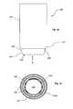
- FIG. 1 ais a schematic representation of a tissue removal tool in perspective view according to an embodiment of the present invention
- FIG. 1 bshow a cross-sectional view along A-A of the tissue removal tool of FIG. 1 a.
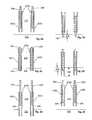
- FIGS. 2 a - 2 fshow longitudinal sectional views of various stages of operation according to an embodiment of the present invention.
- the various embodiments of the devices and methods of the present applicationare useful in manual procedures and systems, as well as in automated procedures and systems.
- the automated systemsmay also be robotically-assisted or computer/software/machine-instruction controlled.
- the tools of the current applicationcan also be used with the robotically-assisted systems and procedures and they could be configured for use with those robotic systems, for example, as described in the commonly-assigned US Patent Publication No. 2007/0106306, the disclosure of which is incorporated herein by reference.
- toolrefers to any number of tools or end effectors that are capable of removing or harvesting various biological tissues, for example, follicular units (“FUs”) from a body surface. While the removal tools described in the present application are very useful in harvesting follicular units, in general, however, the tools of the present invention may be useful for removing biological units or tissue other than FUs from a body surface. In this sense, a body surface can be attached to the body or may be a flap of skin or body tissue removed from the body. Such tools may have many different forms and configurations.
- the toolcomprises a hollow tubular shaft and thus may be labeled, for example, a cannula, a needle, or a punch.
- the distal end of removal toolsfor example, punches, coring devices, cutting and/or trimming devices, needles
- follicular unit harvesting cannulasor tools
- follicular unit harvesting cannulasor tools
- each harvesting cannula designmay have certain benefits (e.g., superior retraction and retention of follicular units, less trauma to the surrounding skin and tissue), or drawbacks (e.g., complex design and/or operation, higher manufacturing costs, increased trauma), relative to the other embodiments.
- selection of a particular harvesting cannula distal end designwill depend on the particular performance criteria sought to be achieved.
- Bio units” or “biological tissue”include discrete units of soft tissue used in cosmetic, diagnostic, and dermatological procedures, for example, various soft tissues, including that extracted for biopsies or grafting.
- Examples of the biological units particularly useful with the present inventionare hair grafts, or follicles, or “follicular unit(s).”
- Other biological unitsmay be soft tissue used for diagnosis of cancer, such as from the areas of the skin, breast, liver, prostate, colon and small bowel, or lungs.
- the term biological unitsencompasses a number of things, though the present invention is particularly useful in hair harvesting, to provide devices and methods for harvesting follicular units (FUs).
- FUsfollicular units
- the term follicular units (or FUs)will be used herein simply as an example for purposes of describing some embodiments of the present invention with the understanding that it represents more broadly biological units.
- a biological unit removal toolis configured to minimize damage to the biological unit being removed and to improve the quality of the removed specimen, preferably preserving its integrity.
- This toolcan be utilized manually, in conjunction with a motor powered instrument, as part of an automated or semi-automated system, and/or be computer or robotically controlled.
- the toolmay be inserted into a skin, for example, by pushing into a body surface, or optionally it may be rotated, and maneuvered to encapsulate and remove biological units from the body surface accordingly.
- FIG. 1 ashows a perspective view of one example of such a tissue removal tool.
- the removal tool 100includes a first elongated body 102 and a second elongated body 104 , which may be substantially coaxially disposed relative to each other.
- the second elongated body 104comprises a sharp distal tip 106 .
- the term “sharp” distal tip 106 as used hereinmeans that it is sharp enough to pierce or cut a skin or body surface (not shown).
- the second elongated bodymay be pushed into the skin such that its sharp distal tip cuts or incises tissue, or skin layers to a desired depth (e.g. through the epidermis, or upper dermis).
- the first elongated body 102comprises a distal tip 108 , which is preferably blunt.
- the blunt distal tip 108 of the first elongated body 102is less sharp than the distal tip 106 .
- the blunt distal tip 108is capable of readily advancing through the incision created by the sharp distal tip 106 of the second elongated body 104 , and continue advancing deeper through the tissue that surrounds a biological unit, such as a follicular unit, without causing any unnecessary damage and/or trauma to the biological unit, and preferably enabling removal of the biological unit while preserving its integrity.
- the elongated body 102is configured to at least partially surround or encapsulate the biological unit, with the lumen 110 configured to receive the biological unit (not shown).
- One or both of the first and second elongated bodies, 102 and 104 respectively,may be axially movable relative to one another, and optionally radially movable relative to one another.
- FIG. 1 bshows an example of an end view of the removal tool 100 , viewed from the direction of arrow A in FIG. 1 a .
- the first elongated body 102comprises a first member or an inner wall 102 a and a second member or an outer wall 102 b , which together form a structure which shelters the second elongated body 104 from direct exposure to, or direct contact with the lumen 110 of the first elongated member 102 .
- the first member or the inner wall 102 adefines the lumen 110 , in which a biological unit can be encapsulated and preferably retained.
- the second member 102 bdefines the outer wall of the removal tool 100 .
- FIG. 1 bshows an example of an end view of the removal tool 100 , viewed from the direction of arrow A in FIG. 1 a .
- the first elongated body 102comprises a first member or an inner wall 102 a and a second member or an outer wall 102 b , which together
- a second elongated body 104is disposed in a gap or a small annular space 107 formed between the inner wall 102 a and the outer wall 102 b of the first elongated member 102 .
- the distal tip 108 of the first elongated body 102comprises a distal tip of the inner wall 102 a and a distal tip of the outer wall 102 b . It is blunt and relatively duller that is less sharp) than the sharp distal tip 106 of the second elongated body 104 , thus reducing the chance of undesired damage to the tissue to be removed, for example, transecting a follicular unit to be harvested.
- the distal tip 108 of the first elongated bodymay be circular, or of any other desired shape.
- the first elongated body 102may comprise a taper 112 , as seen in FIG. 1 a .
- the tapermay be configured in many different ways, for example, by decreasing an overall diameter of the first elongated member at its distal end, or by reducing thickness of the outer wall 102 b , or both outer and inner walls 102 a and 102 b , or by any other means known in the art.
- the second elongated body 104is preferably tubular and it may have the same length or a different length than the first elongated body 102 . As seen in the embodiment of FIG. 1 b , the second elongated body 104 may be substantially concentrically disposed within the wall structure of the first elongated body 102 , such that when a biological unit, such as a follicular unit, enters and moves through the lumen 110 of the first elongated body 102 , it is not exposed to or in a potential contact with the sharp distal tip 106 of the second elongated body.
- a biological unitsuch as a follicular unit
- the operation of the toolincluding various positions of the sharp distal tip of the second elongated body during removal of the biological tissue, is described below in reference to the examples of the embodiments of the method of the invention.
- the sharp distal tip 106 of the second elongated body 104includes a sharp or semi-sharp segment primarily for piercing tissue.
- the second elongated body 104may further comprise a taper 114 towards the sharp distal tip 106 .
- one or both of the elongated bodies 102 and 104may comprise a series of wires, rods or other suitably shaped elements that together form each respective elongated body.
- the first and second elongated bodies, however formed,may comprise a small annular space between them (for example, an annular space 107 in FIG. 1 b ), designed such that the tubes rotate slightly off axis to one another, so as to wobble or be mis-aligned with one another.
- the coaxial tubesmay comprise radial spacers (not shown) that maintain the distance between the coaxial elongated members.
- the elongated bodies 102 and 104may be manufactured from the same type or differing materials, from rigid or semi-rigid materials, e.g. stainless steel hypodermic tubing or other appropriate material, such a titanium or nitinol.
- FIGS. 2 a - 2 fOne method of use of the removal tool 100 according to an embodiment of the invention is illustrated in FIGS. 2 a - 2 f .
- the readeris advised that the focus is on the distal end of the features discussed, and that the proximal end may be configured to suit any particular need.
- the elongated bodies 102 a and 102 bmay be at least partially attached at the proximal ends thereof.
- the tool 100may, for example, be configured to incorporate a handle and/or appropriate sleeves, slidable shafts, or other such structures to move the elongated bodies axially and optionally radially relative to one another.
- the proximal end of the toolmay adapted to enable one or more of a mechanical system, and electromechanical system, a pneumatic system, hydraulic system or a magnetic system for effecting controlled movement of the first and second elongated bodies relative to one another, and to facilitate a semi- or fully-automated tool to be employed.
- either or both of the elongated bodiesmay be operatively coupled to a biasing mechanism, such as a spring mechanism, or other such release mechanism to facilitate movement of the elongated body in the axial direction, in a quick, or slow or otherwise controlled manner.
- the removal toolcan be implemented in a robotically-assisted system, such as those described in the U.S. Publication No. 2007/0106306 already incorporated by reference herein.
- the removal tool 100may be connected directly or indirectly to an automated (e.g., robotic) arm, so that movement of the removal tool relative to the body surface may be performed by either movement of the robotic arm relative to the body surface, or movement of the removal tool relative to the automated arm, or a combination of each.
- Operation of the mechanical system, electromechanical system, pneumatic system, hydraulic system or magnetic systemmay be controlled by an electronic controller such as a computer of the PC type, an embedded processor, a programmable hardware device, or some other device capable of electronic manipulation and processing of data in accordance with a software and/or another logical control system and/or user input.
- an electronic controllersuch as a computer of the PC type, an embedded processor, a programmable hardware device, or some other device capable of electronic manipulation and processing of data in accordance with a software and/or another logical control system and/or user input.
- programmable hardware devicesmay include one or more of a field-programmable gate array (FPGA) or application-specific integrated circuit (ASIC).
- FPGAfield-programmable gate array
- ASICapplication-specific integrated circuit
- FIGS. 2 a - 2 fillustrate an example of a method by which the removal tool 100 may be operated to remove or harvest a biological unit such as, for example, a hair graft, from a donor area such as a scalp or other body surface containing hair.
- FIG. 2 aillustrates the tool 100 positioned above a body surface 202 and the follicular unit or hair graft (not shown) which is intended to be removed from the donor area.
- the second elongated body 104is in its retracted position (e.g., the sharp distal tip of the second elongated body is retracted inside the wall of the first elongated body 102 ), and the lumen 110 of the tool 100 is clear.
- the first member 102 a of the first elongated body 102serves to shield the second elongated body 104 from direct contact or exposure to the lumen 110 of the first elongated body 102 .
- the sharp distal tip 106 of the removal tool 100is also protected from contamination or any other such damage from external elements.
- the useris likewise protected from unintentional puncturing of his/her skin by merely handling the tool 100 .
- the lumen 110in the context of hair transplantation, may comprise a diameter ranging between 0.5-1.5 mm, and preferably about 1.0 mm, thus making it suitable for receiving follicular units, which are naturally occurring aggregates of 1-3 (and much less commonly, 4-5) closely spaced hair follicles.
- FIG. 2 billustrates the sharp distal tip 106 of the second elongated body 104 having advanced or moved such that the body surface 202 is penetrated, perforated, or cut to a first depth 204 .
- the sharp distal tip 106in order to reduce potential damage to the biological tissue, such as a follicular unit, it is preferable to use the sharp distal tip 106 only to pierce the body surface and to create an initial incision. Therefore, it is preferable to keep the first depth 204 to a minimum depth required after which one can successfully continue to dissect tissue with the blunt tip 108 of the first elongated body.
- such first depth 204may be approximately 0.5 mm to 2 mm.
- the movement of the second elongated bodymay comprise rotational as well as translational motion, and the penetration or perforation may be the result of the sharp distal tip 106 having moved towards the body surface 202 at a relatively high speed.
- FIG. 2 cshows the first elongated body 102 having advanced or moved axially relative to the second elongated body 104 , and entering through the body surface 202 , for example, through the incision created by the second elongated body 104 .
- Enabling the distal tip 108 of the first elongated body 102 to enter the incision already created by the sharp distal end 106results in only a single incision or defect on the skin, which is beneficial to the patient.
- by first initiating a path using the sharp distal tip 106 of the second elongated body 104and subsequently entering the same incision with the blunt distal tip 108 of the first elongated body 102 , eliminates the need to recannulate.
- the first elongated body 102continues in its axial (and optionally radial) movement, as illustrated in FIG. 2 d , into the cutaneous and subcutaneous tissue to a second depth 206 of, for example, approximately 5-8 mm using the blunt distal end 108 of the first elongated body 102 to dissect or separate the follicular unit from the surrounding tissue.
- a second depth 206of, for example, approximately 5-8 mm using the blunt distal end 108 of the first elongated body 102 to dissect or separate the follicular unit from the surrounding tissue.
- the lumen 110 of the first elongated body 102substantially encapsulates the follicular unit for harvesting.
- the sharp distal tip 106 of the removal tool 100will more easily pierce the body surface 202 but will be used only until it is inserted to a depth 204 . Any further insertion of the tool will be accomplished using the blunt distal end 108 which will have less chance of cutting (transecting) the portion of the hair follicle lying beneath the body surface 202 .
- the blunt distal end 108 of the first elongated bodymay “push” the hair graft and surrounding tissue into the inner lumen 110 without causing transection thereof.
- the follicular unitis not exposed to the sharp distal end 106 , as the sharp distal end 106 is shielded by the inner wall or the inner member 102 a from the lumen 110 of the first elongated body.
- FIGS. 2 e and 2 fillustrate the withdrawal of the removal tool 100 .
- the second elongated bodymay be withdrawn before or simultaneously with the withdrawal of the first elongated body. Also, it can be withdrawn with the same or a different speed, as long as the second elongated body 104 , including its sharp distal end, is disposed between the members 102 a and 102 b of the first elongated body 102 during the withdrawal. In other words, the sharp distal tip of the second elongated body is located either proximally or flush with a distal tip of the first elongated body.
- the removal tool 100is fully withdrawn, preferably with the follicular unit retained within the lumen 110 thereof.
- FIGS. 2 e and 2 fit can be seen in FIGS. 2 e and 2 f , that at no time, throughout the withdrawal of the removal tool from the depth 206 to its location above the body surface 202 , is the follicular unit exposed to a surface of the second elongated body 104 , and in particular, the follicular unit is not exposed to or in contact with its sharp distal tip 106 . In this manner the follicular unit is protected from any edge or surface that could possibly cause it a trauma or stress. The follicular unit can be removed from the body surface intact, with its integrity preserved. Furthermore, as the distally facing tip 106 of the second elongated body 104 is removed from the body surface 202 , the user is once again protected from any unintended penetration of his/her skin.
- the removal toolpenetrates the body surface 202 , causes a biological unit to enter the lumen 110 therein, and then removes the biological unit from the body surface 202 .
- the biological unitsometimes remains connected in some manner to the tissue that had been surrounding it.
- a follicular unitmay remain attached to the body surface by surrounding connective tissue. Since the surrounding tissue tends to pull back the follicular unit from the removal tool 100 , this sometimes results either in tearing the follicular unit apart, or simply not retaining it in the removal tool 100 .
- One such wayis to utilize suction, a pressure differential, within the lumen 110 of the tool 100 to further transfer the follicular unit in a proximal direction.
- retention structures or deformable elementsin the form of barbs, protrusions, grooves, or any other suitably functioning retention element may be utilized to retain the biological unit within the tool 100 as it is retracted from the body surface 202 .
- the retention member(not shown) can be moved from a retracted to a retention position to retain the biological unit.
- the retention membersmay be deformable and once the biological unit is in the lumen 110 , it is retained therein.
- a retention membermay be incorporated into the elongated body 102 or extend into the lumen 110 from outside the elongated body 102 .
- the retention memberprevents the biological unit from exiting the lumen 110 in the distal direction.
- the retention membermay be integrated into the tool itself, as part of, for example the elongated body 102 .
- a “retention member” as used hereinrefers to a structure, or a mechanism, or a number of structures and/or mechanisms that partially or fully retain biological tissue in a lumen of various removal tools.
- the retention membermay translate into or across the lumen, or radially constrict the lumen in a circumferential manner, for example, simply closing tightly about a follicular unit, located in the lumen to improve its retention and removal without damaging it.
- the removal tool 100can be configured to deliver a fluid or a gas, for example, saline or tumescence fluid, by incorporating a fluid/gas conduit that opens, for example, into the concentric space between the first and the second members 102 a and 102 b respectively.
- the fluid/gasmay be delivered through distal ports or grooves, for example, near the distal tip of the first 102 a and/or second 102 b members. Additional fluids or gas that may be delivered to the tissue layers, as mentioned above, include but not limited to medications, antibiotics, or healing facilitating solutions.
Landscapes
- Health & Medical Sciences (AREA)
- Life Sciences & Earth Sciences (AREA)
- Surgery (AREA)
- Heart & Thoracic Surgery (AREA)
- Engineering & Computer Science (AREA)
- Biomedical Technology (AREA)
- Nuclear Medicine, Radiotherapy & Molecular Imaging (AREA)
- Medical Informatics (AREA)
- Molecular Biology (AREA)
- Animal Behavior & Ethology (AREA)
- General Health & Medical Sciences (AREA)
- Public Health (AREA)
- Veterinary Medicine (AREA)
- Surgical Instruments (AREA)
Abstract
Description
Claims (14)
Priority Applications (2)
| Application Number | Priority Date | Filing Date | Title |
|---|---|---|---|
| US12/783,750US8128639B2 (en) | 2010-05-20 | 2010-05-20 | Tools and methods for harvesting follicular units |
| US13/368,012US8444656B2 (en) | 2010-05-20 | 2012-02-07 | Tools and methods for harvesting follicular units |
Applications Claiming Priority (1)
| Application Number | Priority Date | Filing Date | Title |
|---|---|---|---|
| US12/783,750US8128639B2 (en) | 2010-05-20 | 2010-05-20 | Tools and methods for harvesting follicular units |
Related Child Applications (1)
| Application Number | Title | Priority Date | Filing Date |
|---|---|---|---|
| US13/368,012ContinuationUS8444656B2 (en) | 2010-05-20 | 2012-02-07 | Tools and methods for harvesting follicular units |
Publications (2)
| Publication Number | Publication Date |
|---|---|
| US20110288562A1 US20110288562A1 (en) | 2011-11-24 |
| US8128639B2true US8128639B2 (en) | 2012-03-06 |
Family
ID=44973092
Family Applications (2)
| Application Number | Title | Priority Date | Filing Date |
|---|---|---|---|
| US12/783,750Active2030-10-16US8128639B2 (en) | 2010-05-20 | 2010-05-20 | Tools and methods for harvesting follicular units |
| US13/368,012Active2030-05-29US8444656B2 (en) | 2010-05-20 | 2012-02-07 | Tools and methods for harvesting follicular units |
Family Applications After (1)
| Application Number | Title | Priority Date | Filing Date |
|---|---|---|---|
| US13/368,012Active2030-05-29US8444656B2 (en) | 2010-05-20 | 2012-02-07 | Tools and methods for harvesting follicular units |
Country Status (1)
| Country | Link |
|---|---|
| US (2) | US8128639B2 (en) |
Cited By (15)
| Publication number | Priority date | Publication date | Assignee | Title |
|---|---|---|---|---|
| US20120136373A1 (en)* | 2010-05-20 | 2012-05-31 | Tippett Brian E | Tools and Methods for Harvesting Follicular Units |
| US20140296741A1 (en)* | 2011-07-21 | 2014-10-02 | The General Hospital Corporation | Method and apparatus for subsurface tissue sampling |
| US8998931B2 (en) | 2011-10-17 | 2015-04-07 | Pilofocus, Inc. | Hair restoration |
| US9314082B2 (en) | 2009-09-17 | 2016-04-19 | Pilofocus, Inc. | System and method for extraction of hair follicle |
| US9364252B2 (en) | 2009-09-17 | 2016-06-14 | Pilofocus, Inc. | Hair restoration surgery |
| US9693799B2 (en) | 2009-09-17 | 2017-07-04 | Pilofocus, Inc. | System and method for aligning hair follicle |
| US10251792B2 (en) | 2013-02-20 | 2019-04-09 | Cytrellis Biosystems, Inc. | Methods and devices for skin tightening |
| US10278677B2 (en) | 2011-01-28 | 2019-05-07 | The General Hospital Corporation | Apparatus and method for tissue biopsy |
| US10327800B2 (en) | 2011-01-28 | 2019-06-25 | The General Hospital Corporation | Method and apparatus for skin resurfacing |
| US10555754B2 (en) | 2013-08-09 | 2020-02-11 | Cytrellis Biosystems, Inc. | Methods and apparatuses for skin treatment using non-thermal tissue ablation |
| US10953143B2 (en) | 2013-12-19 | 2021-03-23 | Cytrellis Biosystems, Inc. | Methods and devices for manipulating subdermal fat |
| US11166743B2 (en) | 2016-03-29 | 2021-11-09 | Cytrellis Biosystems, Inc. | Devices and methods for cosmetic skin resurfacing |
| US11324534B2 (en) | 2014-11-14 | 2022-05-10 | Cytrellis Biosystems, Inc. | Devices and methods for ablation of the skin |
| US11337720B2 (en) | 2011-07-21 | 2022-05-24 | The General Hospital Corporation | Method and apparatus for damage and removal of fat |
| US11464954B2 (en) | 2016-09-21 | 2022-10-11 | Cytrellis Biosystems, Inc. | Devices and methods for cosmetic skin resurfacing |
Families Citing this family (5)
| Publication number | Priority date | Publication date | Assignee | Title |
|---|---|---|---|---|
| US9414889B2 (en) | 2009-09-04 | 2016-08-16 | Restoration Robotics, Inc. | Follicular unit harvesting tool |
| EP2598037B1 (en)* | 2010-07-30 | 2016-11-02 | Cook Medical Technologies LLC | Coaxial incisional full-core biopsy needle |
| KR20160010203A (en)* | 2014-07-18 | 2016-01-27 | 한국전자통신연구원 | Apparatus and method for follicle loading |
| CN105852941B (en)* | 2016-03-31 | 2018-03-27 | 陈晓阳 | Sucker shape foreign bodies in airway extractor |
| US10853928B2 (en) | 2019-03-29 | 2020-12-01 | Apple Inc. | Image fusion processing module |
Citations (55)
| Publication number | Priority date | Publication date | Assignee | Title |
|---|---|---|---|---|
| US3605721A (en) | 1969-11-03 | 1971-09-20 | Ismet Hallac | Biopsy needle |
| US3998230A (en) | 1974-10-22 | 1976-12-21 | Hairegenics, Inc. | Hair transplant process |
| US4160453A (en) | 1975-12-05 | 1979-07-10 | Hairegenics, Inc. | Apparatus for implanting hair |
| US4708147A (en) | 1985-02-25 | 1987-11-24 | Haaga John R | Universal biopsy needle |
| US4716901A (en) | 1984-09-27 | 1988-01-05 | Pratt Burnerd International Limited | Surgical appliance for forming an opening through the skin |
| US4785826A (en) | 1987-03-02 | 1988-11-22 | Ward John L | Biopsy instrument |
| US5036860A (en) | 1989-11-24 | 1991-08-06 | Medical Device Technologies, Inc. | Disposable soft tissue biopsy apparatus |
| US5423330A (en) | 1993-03-10 | 1995-06-13 | The University Of Miami | Capsule suction punch instrument and method of use |
| US5480388A (en) | 1991-09-13 | 1996-01-02 | Zadini; Filiberto P. | Semi-automatic cannulation device |
| US5573008A (en) | 1993-10-29 | 1996-11-12 | Boston Scientific Corporation | Multiple biopsy sampling coring device |
| US5651781A (en) | 1995-04-20 | 1997-07-29 | Grace-Wells Technology Partners No. 1, L.P. | Surgical cutting instrument |
| US5788651A (en) | 1995-01-26 | 1998-08-04 | Weilandt; Anders | Instrument and apparatus for biopsy |
| US5817120A (en) | 1997-02-10 | 1998-10-06 | Rassman; William R. | Hair implanting instrument |
| US5885226A (en) | 1991-12-13 | 1999-03-23 | International Medical Technologies Corporation | Bone marrow biopsy needle with cutting and/or retaining device at distal end |
| US5910121A (en) | 1997-01-03 | 1999-06-08 | Gallini S.R.L. | Biopsy device |
| EP0966920A2 (en) | 1998-06-24 | 1999-12-29 | Rubicor Medical, Inc. | Fine needle and core biopsy devices |
| US6015391A (en) | 1998-10-06 | 2000-01-18 | Medsol, Corp. | Biopsy needle structure |
| US6080175A (en) | 1998-07-29 | 2000-06-27 | Corvascular, Inc. | Surgical cutting instrument and method of use |
| US6110127A (en) | 1998-02-17 | 2000-08-29 | Olympus Optical, Co., Ltd. | Medical instrument for use in combination with an endoscope |
| US6142955A (en) | 1997-09-19 | 2000-11-07 | United States Surgical Corporation | Biopsy apparatus and method |
| US6273861B1 (en) | 1997-01-30 | 2001-08-14 | Scimed Life Systems, Inc. | Pneumatically actuated tissue sampling device |
| US6306142B1 (en) | 1998-07-17 | 2001-10-23 | Johnson & Johnson | Method and apparatus for harvesting and implanting bone plugs |
| WO2002007602A2 (en) | 2000-07-20 | 2002-01-31 | H.S. Hospital Service S.P.A. | Device for transcutaneous biopsy |
| US6395002B1 (en) | 2000-01-18 | 2002-05-28 | Alan G. Ellman | Electrosurgical instrument for ear surgery |
| WO2002065919A1 (en) | 2001-02-16 | 2002-08-29 | Jacques Phillibert Janssens | Device for taking a tissue sample |
| US6461369B1 (en) | 1999-08-05 | 2002-10-08 | Jung Chul Kim | Hair transplanter |
| US20020151821A1 (en) | 2000-07-24 | 2002-10-17 | Pietro Castellacci | Needle of the biopsy type or for taking other samples from human or animal organs |
| US6471709B1 (en) | 1998-10-30 | 2002-10-29 | Vivant Medical, Inc. | Expandable ring percutaneous tissue removal device |
| US6488636B2 (en) | 1997-09-19 | 2002-12-03 | United States Surgical Corporation | Biopsy apparatus |
| EP1293167A2 (en) | 2001-09-14 | 2003-03-19 | TuiLaser AG | Instrument for cutting and removing tissue |
| US6554779B2 (en) | 1998-02-20 | 2003-04-29 | United States Surgical Corporation | Biopsy instrument driver apparatus |
| US20030097079A1 (en) | 2001-10-19 | 2003-05-22 | Garcia Maurice M. | Biopsy needle sheath |
| US20040220589A1 (en) | 2003-04-29 | 2004-11-04 | Feller Alan S. | Method and apparatus for follicular extraction and transplantation |
| US6875220B2 (en) | 2002-12-30 | 2005-04-05 | Cybersonics, Inc. | Dual probe |
| US20050085838A1 (en) | 2003-02-25 | 2005-04-21 | Bennie Thompson | Method of operating a biopsy device |
| US6939318B2 (en) | 2002-05-03 | 2005-09-06 | Boston Scientific Scimed, Inc. | Method, tool, and system for deploying an implant into the body |
| WO2005109799A2 (en) | 2004-04-08 | 2005-11-17 | Hsc Development Llc | Follicular extraction method and device |
| US20060161179A1 (en)* | 2004-12-23 | 2006-07-20 | Kachenmeister Robert M | Follicular transplantation device and method |
| US20060178678A1 (en)* | 2004-03-09 | 2006-08-10 | Cole John P | Enhanced follicular extraction punch and method |
| US20070123800A1 (en) | 1999-09-28 | 2007-05-31 | Boston Scientific Scimed, Inc. | Endoscopic submucosal core biopsy device |
| US20070142743A1 (en) | 2005-12-16 | 2007-06-21 | Provencher Kevin M | Tissue sample needle actuator system and apparatus and method of using same |
| US20070149985A1 (en) | 2004-03-09 | 2007-06-28 | Cole John P | Follicular extraction punch and method |
| US7261721B2 (en) | 2002-12-16 | 2007-08-28 | Feller Alan S | Method and apparatus for follicular extraction and transplantation |
| US20070213741A1 (en) | 2004-03-09 | 2007-09-13 | Cole John P | Follicular extraction punch and method |
| US20070213634A1 (en) | 2006-02-24 | 2007-09-13 | Boston Scientific Scimed, Inc. | Obtaining a tissue sample |
| US20080033455A1 (en) | 2006-08-03 | 2008-02-07 | Rassman William R | Hair extraction device and method for its use |
| US20080045858A1 (en) | 2003-08-07 | 2008-02-21 | Marco Tessitore | Device for Transcutaneous Biopsy of Tissues |
| WO2008027829A2 (en) | 2006-08-29 | 2008-03-06 | Kyphon Sarl | Tissue extraction device and method of using the same |
| US20080154150A1 (en) | 2006-05-01 | 2008-06-26 | Goldenberg Alec S | Bone marrow biopsy needle |
| US20080154296A1 (en) | 2006-12-22 | 2008-06-26 | The Spectranetics Corporation | Tissue Separating Systems and Methods |
| US20080234699A1 (en) | 2007-03-19 | 2008-09-25 | Oostman Jr Clifford A | Biological unit removal tools with concentric tubes |
| WO2009017445A1 (en) | 2007-08-02 | 2009-02-05 | Novoaim Ab | Surgical kits and methods |
| US20090227895A1 (en) | 2008-03-04 | 2009-09-10 | Goldenberg Alec S | Biopsy needle |
| US20090240261A1 (en) | 2008-03-18 | 2009-09-24 | Restoration Robotics, Inc. | Biological unit removal tools with movable retention member |
| US7621933B2 (en) | 2005-09-30 | 2009-11-24 | Restoration Robotics, Inc. | Tool assembly for harvesting and implanting follicular units |
Family Cites Families (3)
| Publication number | Priority date | Publication date | Assignee | Title |
|---|---|---|---|---|
| US5423806A (en)* | 1993-10-01 | 1995-06-13 | Medtronic, Inc. | Laser extractor for an implanted object |
| US9414889B2 (en)* | 2009-09-04 | 2016-08-16 | Restoration Robotics, Inc. | Follicular unit harvesting tool |
| US8128639B2 (en)* | 2010-05-20 | 2012-03-06 | Restoration Robotics, Inc. | Tools and methods for harvesting follicular units |
- 2010
- 2010-05-20USUS12/783,750patent/US8128639B2/enactiveActive
- 2012
- 2012-02-07USUS13/368,012patent/US8444656B2/enactiveActive
Patent Citations (58)
| Publication number | Priority date | Publication date | Assignee | Title |
|---|---|---|---|---|
| US3605721A (en) | 1969-11-03 | 1971-09-20 | Ismet Hallac | Biopsy needle |
| US3998230A (en) | 1974-10-22 | 1976-12-21 | Hairegenics, Inc. | Hair transplant process |
| US4160453A (en) | 1975-12-05 | 1979-07-10 | Hairegenics, Inc. | Apparatus for implanting hair |
| US4716901A (en) | 1984-09-27 | 1988-01-05 | Pratt Burnerd International Limited | Surgical appliance for forming an opening through the skin |
| US4708147A (en) | 1985-02-25 | 1987-11-24 | Haaga John R | Universal biopsy needle |
| US4785826A (en) | 1987-03-02 | 1988-11-22 | Ward John L | Biopsy instrument |
| US5036860A (en) | 1989-11-24 | 1991-08-06 | Medical Device Technologies, Inc. | Disposable soft tissue biopsy apparatus |
| US5480388A (en) | 1991-09-13 | 1996-01-02 | Zadini; Filiberto P. | Semi-automatic cannulation device |
| US5885226A (en) | 1991-12-13 | 1999-03-23 | International Medical Technologies Corporation | Bone marrow biopsy needle with cutting and/or retaining device at distal end |
| US5423330A (en) | 1993-03-10 | 1995-06-13 | The University Of Miami | Capsule suction punch instrument and method of use |
| US5573008A (en) | 1993-10-29 | 1996-11-12 | Boston Scientific Corporation | Multiple biopsy sampling coring device |
| US5788651A (en) | 1995-01-26 | 1998-08-04 | Weilandt; Anders | Instrument and apparatus for biopsy |
| US5651781A (en) | 1995-04-20 | 1997-07-29 | Grace-Wells Technology Partners No. 1, L.P. | Surgical cutting instrument |
| US5910121A (en) | 1997-01-03 | 1999-06-08 | Gallini S.R.L. | Biopsy device |
| US6273861B1 (en) | 1997-01-30 | 2001-08-14 | Scimed Life Systems, Inc. | Pneumatically actuated tissue sampling device |
| US5817120A (en) | 1997-02-10 | 1998-10-06 | Rassman; William R. | Hair implanting instrument |
| US6142955A (en) | 1997-09-19 | 2000-11-07 | United States Surgical Corporation | Biopsy apparatus and method |
| US6488636B2 (en) | 1997-09-19 | 2002-12-03 | United States Surgical Corporation | Biopsy apparatus |
| US6110127A (en) | 1998-02-17 | 2000-08-29 | Olympus Optical, Co., Ltd. | Medical instrument for use in combination with an endoscope |
| US6554779B2 (en) | 1998-02-20 | 2003-04-29 | United States Surgical Corporation | Biopsy instrument driver apparatus |
| US6086543A (en) | 1998-06-24 | 2000-07-11 | Rubicor Medical, Inc. | Fine needle and core biopsy devices and methods |
| EP0966920A2 (en) | 1998-06-24 | 1999-12-29 | Rubicor Medical, Inc. | Fine needle and core biopsy devices |
| US6306142B1 (en) | 1998-07-17 | 2001-10-23 | Johnson & Johnson | Method and apparatus for harvesting and implanting bone plugs |
| US6080175A (en) | 1998-07-29 | 2000-06-27 | Corvascular, Inc. | Surgical cutting instrument and method of use |
| US6015391A (en) | 1998-10-06 | 2000-01-18 | Medsol, Corp. | Biopsy needle structure |
| US6471709B1 (en) | 1998-10-30 | 2002-10-29 | Vivant Medical, Inc. | Expandable ring percutaneous tissue removal device |
| US6461369B1 (en) | 1999-08-05 | 2002-10-08 | Jung Chul Kim | Hair transplanter |
| US20070123800A1 (en) | 1999-09-28 | 2007-05-31 | Boston Scientific Scimed, Inc. | Endoscopic submucosal core biopsy device |
| US6395002B1 (en) | 2000-01-18 | 2002-05-28 | Alan G. Ellman | Electrosurgical instrument for ear surgery |
| WO2002007602A2 (en) | 2000-07-20 | 2002-01-31 | H.S. Hospital Service S.P.A. | Device for transcutaneous biopsy |
| US20020151821A1 (en) | 2000-07-24 | 2002-10-17 | Pietro Castellacci | Needle of the biopsy type or for taking other samples from human or animal organs |
| WO2002065919A1 (en) | 2001-02-16 | 2002-08-29 | Jacques Phillibert Janssens | Device for taking a tissue sample |
| EP1293167A2 (en) | 2001-09-14 | 2003-03-19 | TuiLaser AG | Instrument for cutting and removing tissue |
| US20030097079A1 (en) | 2001-10-19 | 2003-05-22 | Garcia Maurice M. | Biopsy needle sheath |
| US6939318B2 (en) | 2002-05-03 | 2005-09-06 | Boston Scientific Scimed, Inc. | Method, tool, and system for deploying an implant into the body |
| US7261721B2 (en) | 2002-12-16 | 2007-08-28 | Feller Alan S | Method and apparatus for follicular extraction and transplantation |
| US6875220B2 (en) | 2002-12-30 | 2005-04-05 | Cybersonics, Inc. | Dual probe |
| US20050085838A1 (en) | 2003-02-25 | 2005-04-21 | Bennie Thompson | Method of operating a biopsy device |
| US20040220589A1 (en) | 2003-04-29 | 2004-11-04 | Feller Alan S. | Method and apparatus for follicular extraction and transplantation |
| US20080045858A1 (en) | 2003-08-07 | 2008-02-21 | Marco Tessitore | Device for Transcutaneous Biopsy of Tissues |
| US20060178678A1 (en)* | 2004-03-09 | 2006-08-10 | Cole John P | Enhanced follicular extraction punch and method |
| US20070149985A1 (en) | 2004-03-09 | 2007-06-28 | Cole John P | Follicular extraction punch and method |
| US20070213741A1 (en) | 2004-03-09 | 2007-09-13 | Cole John P | Follicular extraction punch and method |
| WO2005109799A2 (en) | 2004-04-08 | 2005-11-17 | Hsc Development Llc | Follicular extraction method and device |
| US20050267506A1 (en) | 2004-04-08 | 2005-12-01 | Harris James A | Follicular extraction method and device |
| US20060161179A1 (en)* | 2004-12-23 | 2006-07-20 | Kachenmeister Robert M | Follicular transplantation device and method |
| US7621934B2 (en) | 2005-09-30 | 2009-11-24 | Restoration Robotics, Inc | Methods of harvesting and implanting follicular units using a coaxial tool |
| US7621933B2 (en) | 2005-09-30 | 2009-11-24 | Restoration Robotics, Inc. | Tool assembly for harvesting and implanting follicular units |
| US20070142743A1 (en) | 2005-12-16 | 2007-06-21 | Provencher Kevin M | Tissue sample needle actuator system and apparatus and method of using same |
| US20070213634A1 (en) | 2006-02-24 | 2007-09-13 | Boston Scientific Scimed, Inc. | Obtaining a tissue sample |
| US20080154150A1 (en) | 2006-05-01 | 2008-06-26 | Goldenberg Alec S | Bone marrow biopsy needle |
| US20080033455A1 (en) | 2006-08-03 | 2008-02-07 | Rassman William R | Hair extraction device and method for its use |
| WO2008027829A2 (en) | 2006-08-29 | 2008-03-06 | Kyphon Sarl | Tissue extraction device and method of using the same |
| US20080154296A1 (en) | 2006-12-22 | 2008-06-26 | The Spectranetics Corporation | Tissue Separating Systems and Methods |
| US20080234699A1 (en) | 2007-03-19 | 2008-09-25 | Oostman Jr Clifford A | Biological unit removal tools with concentric tubes |
| WO2009017445A1 (en) | 2007-08-02 | 2009-02-05 | Novoaim Ab | Surgical kits and methods |
| US20090227895A1 (en) | 2008-03-04 | 2009-09-10 | Goldenberg Alec S | Biopsy needle |
| US20090240261A1 (en) | 2008-03-18 | 2009-09-24 | Restoration Robotics, Inc. | Biological unit removal tools with movable retention member |
Non-Patent Citations (5)
| Title |
|---|
| Harris, James A. "New Methodology and Instrumentation for Follicular Unit Extraction: Lower Follicle Transection Rates and Expanded Patient Candidacy", Department of Otolaryngology/Head and Neck Surgery, Univ. of Colorado Health Sciences Center, Denver, Colorado. Copyright 2006 by the American Society of Dermatologic Surgery, Inc. Published by BC Decker, Inc., Dermatologic Surgery, vol. 32. |
| Office Action dated Mar. 28, 2011, in relation to commonly assigned U.S. Appl. No. 12/050,917 (19 pages). |
| Office Action dated Oct. 25, 2011, in relation to commonly assigned U.S. Appl. No. 12/050,917 (13 pages). |
| Response filed Jul. 27, 2011 to Office Action dated Mar. 28, 2011, in relation to commonly assigned U.S. Appl. No. 12/050,917 (10 pages). |
| Robert M Bernstein, MD; William R Rassman, MD. "New Instrumentation for Three-Step Follicular Unit Extraction". Hair Transplant Forum International, vol. 16, No. 1, Jan./Feb. 2006. |
Cited By (26)
| Publication number | Priority date | Publication date | Assignee | Title |
|---|---|---|---|---|
| US9364252B2 (en) | 2009-09-17 | 2016-06-14 | Pilofocus, Inc. | Hair restoration surgery |
| US9693799B2 (en) | 2009-09-17 | 2017-07-04 | Pilofocus, Inc. | System and method for aligning hair follicle |
| US9314082B2 (en) | 2009-09-17 | 2016-04-19 | Pilofocus, Inc. | System and method for extraction of hair follicle |
| US8444656B2 (en)* | 2010-05-20 | 2013-05-21 | Restoration Robotics, Inc. | Tools and methods for harvesting follicular units |
| US20120136373A1 (en)* | 2010-05-20 | 2012-05-31 | Tippett Brian E | Tools and Methods for Harvesting Follicular Units |
| US11419588B2 (en) | 2011-01-28 | 2022-08-23 | The General Hospital Corporation | Apparatus and method for tissue biopsy |
| US10278677B2 (en) | 2011-01-28 | 2019-05-07 | The General Hospital Corporation | Apparatus and method for tissue biopsy |
| US10327800B2 (en) | 2011-01-28 | 2019-06-25 | The General Hospital Corporation | Method and apparatus for skin resurfacing |
| US11364049B2 (en) | 2011-01-28 | 2022-06-21 | The General Hospital Corporation | Method and apparatus for skin resurfacing |
| US11337720B2 (en) | 2011-07-21 | 2022-05-24 | The General Hospital Corporation | Method and apparatus for damage and removal of fat |
| US12171455B2 (en) | 2011-07-21 | 2024-12-24 | The General Hospital Corporation | Method and apparatus for damage and removal of fat |
| US20140296741A1 (en)* | 2011-07-21 | 2014-10-02 | The General Hospital Corporation | Method and apparatus for subsurface tissue sampling |
| US9861386B2 (en) | 2011-10-17 | 2018-01-09 | Pilofocus, Inc. | Hair restoration |
| US8998931B2 (en) | 2011-10-17 | 2015-04-07 | Pilofocus, Inc. | Hair restoration |
| US10543127B2 (en) | 2013-02-20 | 2020-01-28 | Cytrellis Biosystems, Inc. | Methods and devices for skin tightening |
| US11534344B2 (en) | 2013-02-20 | 2022-12-27 | Cytrellis Biosystems, Inc. | Methods and devices for skin tightening |
| US12023226B2 (en) | 2013-02-20 | 2024-07-02 | Cytrellis Biosystems, Inc. | Methods and devices for skin tightening |
| US10251792B2 (en) | 2013-02-20 | 2019-04-09 | Cytrellis Biosystems, Inc. | Methods and devices for skin tightening |
| US10555754B2 (en) | 2013-08-09 | 2020-02-11 | Cytrellis Biosystems, Inc. | Methods and apparatuses for skin treatment using non-thermal tissue ablation |
| US12150671B2 (en) | 2013-08-09 | 2024-11-26 | Cytrellis Biosystems, Inc. | Methods and apparatuses for skin treatment using non-thermal tissue ablation |
| US10953143B2 (en) | 2013-12-19 | 2021-03-23 | Cytrellis Biosystems, Inc. | Methods and devices for manipulating subdermal fat |
| US11324534B2 (en) | 2014-11-14 | 2022-05-10 | Cytrellis Biosystems, Inc. | Devices and methods for ablation of the skin |
| US11896261B2 (en) | 2014-11-14 | 2024-02-13 | Cytrellis Biosystems, Inc. | Devices and methods for ablation of the skin |
| US12256957B2 (en) | 2014-11-14 | 2025-03-25 | Cytrellis Biosystems, Inc. | Devices and methods for ablation of the skin |
| US11166743B2 (en) | 2016-03-29 | 2021-11-09 | Cytrellis Biosystems, Inc. | Devices and methods for cosmetic skin resurfacing |
| US11464954B2 (en) | 2016-09-21 | 2022-10-11 | Cytrellis Biosystems, Inc. | Devices and methods for cosmetic skin resurfacing |
Also Published As
| Publication number | Publication date |
|---|---|
| US20110288562A1 (en) | 2011-11-24 |
| US20120136373A1 (en) | 2012-05-31 |
| US8444656B2 (en) | 2013-05-21 |
Similar Documents
| Publication | Publication Date | Title |
|---|---|---|
| US8128639B2 (en) | Tools and methods for harvesting follicular units | |
| US9017343B2 (en) | Biological unit removal tools with movable retention member | |
| US8986324B2 (en) | Systems and methods for harvesting follicular units | |
| US9084465B2 (en) | Biological unit removal tools and methods | |
| US8512356B2 (en) | Follicular unit harvesting tools including devices and their use for severing connective tissue | |
| US8876839B2 (en) | Follicula unit removal tool with pivoting retention member and method of its use | |
| US9301736B2 (en) | Fine needle biopsy with adaptor | |
| KR102517178B1 (en) | Biopsy kit and method of removal of a piece of target tissue | |
| US20140171968A1 (en) | Follicular Unit Harvesting Tools for Severing Connective Tissue and Methods of Their Use |
Legal Events
| Date | Code | Title | Description |
|---|---|---|---|
| AS | Assignment | Owner name:RESTORATION ROBOTICS, INC., CALIFORNIA Free format text:ASSIGNMENT OF ASSIGNORS INTEREST;ASSIGNOR:TIPPETT, BRIAN E;REEL/FRAME:024415/0319 Effective date:20100520 | |
| STCF | Information on status: patent grant | Free format text:PATENTED CASE | |
| FPAY | Fee payment | Year of fee payment:4 | |
| AS | Assignment | Owner name:SOLAR CAPITAL LTD., NEW YORK Free format text:SHORT-FORM PATENT SECURITY AGREEMENT;ASSIGNOR:RESTORATION ROBOTICS, INC.;REEL/FRAME:046125/0518 Effective date:20180510 | |
| MAFP | Maintenance fee payment | Free format text:PAYMENT OF MAINTENANCE FEE, 8TH YR, SMALL ENTITY (ORIGINAL EVENT CODE: M2552); ENTITY STATUS OF PATENT OWNER: SMALL ENTITY Year of fee payment:8 | |
| AS | Assignment | Owner name:RESTORATION ROBOTICS, INC., CALIFORNIA Free format text:RELEASE BY SECURED PARTY;ASSIGNOR:SOLAR CAPITAL LTD.;REEL/FRAME:050965/0765 Effective date:20191107 Owner name:RESTORATION ROBOTICS, INC., CALIFORNIA Free format text:TERMINATION OF PATENT SECURITY AGREEMENT;ASSIGNOR:SOLAR CAPITAL LTD.;REEL/FRAME:050966/0741 Effective date:20191107 | |
| AS | Assignment | Owner name:MADRYN HEALTH PARTNERS, LP, NEW YORK Free format text:SECURITY INTEREST;ASSIGNOR:VENUS CONCEPT INC.;REEL/FRAME:051156/0892 Effective date:20161011 | |
| AS | Assignment | Owner name:VENUS CONCEPT INC., CALIFORNIA Free format text:CHANGE OF NAME;ASSIGNOR:RESTORATION ROBOTICS, INC.;REEL/FRAME:057843/0981 Effective date:20191107 | |
| AS | Assignment | Owner name:VENUS CONCEPT INC., CALIFORNIA Free format text:CHANGE OF NAME;ASSIGNOR:RESTORATION ROBOTICS, INC.;REEL/FRAME:057788/0712 Effective date:20191107 | |
| MAFP | Maintenance fee payment | Free format text:PAYMENT OF MAINTENANCE FEE, 12TH YR, SMALL ENTITY (ORIGINAL EVENT CODE: M2553); ENTITY STATUS OF PATENT OWNER: SMALL ENTITY Year of fee payment:12 | |
| AS | Assignment | Owner name:EW HEALTHCARE PARTNERS, L.P., TEXAS Free format text:SECURITY INTEREST;ASSIGNOR:VENUS CONCEPT INC.;REEL/FRAME:066354/0565 Effective date:20240118 |