US8128636B2 - Device and method for removing lumenless leads - Google Patents
Device and method for removing lumenless leadsDownload PDFInfo
- Publication number
- US8128636B2 US8128636B2US11/704,852US70485207AUS8128636B2US 8128636 B2US8128636 B2US 8128636B2US 70485207 AUS70485207 AUS 70485207AUS 8128636 B2US8128636 B2US 8128636B2
- Authority
- US
- United States
- Prior art keywords
- collar
- wire
- eyelet
- length
- elongated structure
- Prior art date
- Legal status (The legal status is an assumption and is not a legal conclusion. Google has not performed a legal analysis and makes no representation as to the accuracy of the status listed.)
- Active, expires
Links
- 238000000034methodMethods0.000titledescription19
- 238000005476solderingMethods0.000claimsdescription4
- 238000003466weldingMethods0.000claimsdescription4
- 229910000679solderInorganic materials0.000claimsdescription2
- 230000000747cardiac effectEffects0.000abstractdescription10
- 210000001519tissueAnatomy0.000description17
- 239000011810insulating materialSubstances0.000description15
- 210000003462veinAnatomy0.000description11
- 230000007246mechanismEffects0.000description9
- 230000003176fibrotic effectEffects0.000description8
- 238000009413insulationMethods0.000description8
- WABPQHHGFIMREM-OIOBTWANSA-Nlead-204Chemical compound[204Pb]WABPQHHGFIMREM-OIOBTWANSA-N0.000description7
- 239000004020conductorSubstances0.000description6
- 239000000463materialSubstances0.000description6
- 238000002788crimpingMethods0.000description4
- 238000005520cutting processMethods0.000description4
- 208000014674injuryDiseases0.000description4
- 230000008733traumaEffects0.000description4
- 239000000203mixtureSubstances0.000description3
- 239000004033plasticSubstances0.000description3
- 229920003023plasticPolymers0.000description3
- 229910001220stainless steelInorganic materials0.000description3
- 239000010935stainless steelSubstances0.000description3
- 210000001321subclavian veinAnatomy0.000description3
- 238000001356surgical procedureMethods0.000description3
- 210000001367arteryAnatomy0.000description2
- 230000000295complement effectEffects0.000description2
- 239000002131composite materialSubstances0.000description2
- 230000009977dual effectEffects0.000description2
- 230000006870functionEffects0.000description2
- 239000002184metalSubstances0.000description2
- 229910052751metalInorganic materials0.000description2
- 229920001296polysiloxanePolymers0.000description2
- 229920002635polyurethanePolymers0.000description2
- 239000004814polyurethaneSubstances0.000description2
- 210000005241right ventricleAnatomy0.000description2
- 239000007779soft materialSubstances0.000description2
- 230000004936stimulating effectEffects0.000description2
- 238000011282treatmentMethods0.000description2
- 230000002792vascularEffects0.000description2
- 239000004593EpoxySubstances0.000description1
- 229910018487Ni—CrInorganic materials0.000description1
- 208000010378Pulmonary EmbolismDiseases0.000description1
- 206010040047SepsisDiseases0.000description1
- 208000006011StrokeDiseases0.000description1
- 208000007536ThrombosisDiseases0.000description1
- 206010047281Ventricular arrhythmiaDiseases0.000description1
- 208000027418Wounds and injuryDiseases0.000description1
- HZEWFHLRYVTOIW-UHFFFAOYSA-N[Ti].[Ni]Chemical compound[Ti].[Ni]HZEWFHLRYVTOIW-UHFFFAOYSA-N0.000description1
- 230000009471actionEffects0.000description1
- 229910045601alloyInorganic materials0.000description1
- 239000000956alloySubstances0.000description1
- 230000004075alterationEffects0.000description1
- 229910052782aluminiumInorganic materials0.000description1
- XAGFODPZIPBFFR-UHFFFAOYSA-NaluminiumChemical compound[Al]XAGFODPZIPBFFR-UHFFFAOYSA-N0.000description1
- 238000005452bendingMethods0.000description1
- 230000008901benefitEffects0.000description1
- 239000008280bloodSubstances0.000description1
- 210000004369bloodAnatomy0.000description1
- 210000001124body fluidAnatomy0.000description1
- 239000010839body fluidSubstances0.000description1
- 238000009954braidingMethods0.000description1
- VNNRSPGTAMTISX-UHFFFAOYSA-Nchromium nickelChemical compound[Cr].[Ni]VNNRSPGTAMTISX-UHFFFAOYSA-N0.000description1
- 239000011248coating agentSubstances0.000description1
- 238000000576coating methodMethods0.000description1
- 230000006835compressionEffects0.000description1
- 238000007906compressionMethods0.000description1
- 230000006378damageEffects0.000description1
- 230000001862defibrillatory effectEffects0.000description1
- 230000010339dilationEffects0.000description1
- 238000002224dissectionMethods0.000description1
- 239000012777electrically insulating materialSubstances0.000description1
- 238000005538encapsulationMethods0.000description1
- 206010014665endocarditisDiseases0.000description1
- 230000003511endothelial effectEffects0.000description1
- 239000011152fibreglassSubstances0.000description1
- 239000012530fluidSubstances0.000description1
- 235000019589hardnessNutrition0.000description1
- 210000002837heart atriumAnatomy0.000description1
- 230000004217heart functionEffects0.000description1
- 210000003709heart valveAnatomy0.000description1
- 238000003780insertionMethods0.000description1
- 230000037431insertionEffects0.000description1
- 230000002452interceptive effectEffects0.000description1
- 238000003754machiningMethods0.000description1
- 229910001092metal group alloyInorganic materials0.000description1
- 150000002739metalsChemical class0.000description1
- 238000012986modificationMethods0.000description1
- 230000004048modificationEffects0.000description1
- 208000010125myocardial infarctionDiseases0.000description1
- 229910001000nickel titaniumInorganic materials0.000description1
- 206010033675panniculitisDiseases0.000description1
- 230000001737promoting effectEffects0.000description1
- 238000000926separation methodMethods0.000description1
- 208000013223septicemiaDiseases0.000description1
- 230000009528severe injuryEffects0.000description1
- 210000004304subcutaneous tissueAnatomy0.000description1
- 210000000779thoracic wallAnatomy0.000description1
- 239000013598vectorSubstances0.000description1
- 210000002620vena cava superiorAnatomy0.000description1
Images


Classifications
- A—HUMAN NECESSITIES
- A61—MEDICAL OR VETERINARY SCIENCE; HYGIENE
- A61N—ELECTROTHERAPY; MAGNETOTHERAPY; RADIATION THERAPY; ULTRASOUND THERAPY
- A61N1/00—Electrotherapy; Circuits therefor
- A61N1/02—Details
- A61N1/04—Electrodes
- A61N1/05—Electrodes for implantation or insertion into the body, e.g. heart electrode
- A61N1/056—Transvascular endocardial electrode systems
- A61N1/057—Anchoring means; Means for fixing the head inside the heart
- A61N2001/0578—Anchoring means; Means for fixing the head inside the heart having means for removal or extraction
Definitions
- This inventionrelates generally to a device and method for removing an implanted elongated structure from a patient, and more particularly, to a device and method for removing an implanted cardiac lead from a patient.
- a variety of medical treatments and surgical methodsentail implanting an elongated structure in the body of a human or veterinary patient.
- elongated structuresinclude catheters, sheaths and cardiac electrical leads (such as pacemaker leads and defibrillator leads), and a variety of other devices.
- cardiac electrical leadssuch as pacemaker leads and defibrillator leads
- problemscan be encountered in attempting removal of an elongated structure implanted in biological tissue.
- a heart pacemakeris typically implanted in a subcutaneous tissue pocket in the chest wall of a patient, and a pacemaker lead is positioned in the vascular system of the patient, extending from the pacemaker and through a vein into a chamber of the patient's heart.
- the pacemaker leadcommonly includes a coiled structure such as an electrical wire coil for conducting electrical signals (such as stimulating and/or sensing signals) between the pacemaker and the heart.
- Defibrillator leadsare generally similar and, like pacemaker leads, are located about the heart, but are affixed both internally and externally of the heart.
- Some leadsinclude one or more coaxial or lateral helical wire coils having a hollow inner passageway, or lumen, that extends the entire length of the wire coil or coils.
- leadsmay be made with a cable or a tightly wound coil without a hollow inner passageway.
- the cable or wire coilsare surrounded by an electrically insulating material such as a flexible tube, sheath or coating.
- the insulating materialgenerally formed of silicone or polyurethane, serves simultaneously to protect the cable and wire coils from body fluids, and in the case of bi-polar leads, to insulate the wire coils from one another.
- pacemaker and defibrillator leadsmay become encapsulated by fibrotic tissue against the heart itself or the wall of the vein, or against other surrounding tissue. Encapsulation is especially encountered in areas where the velocity of the flow of blood is low.
- the fibrotic tissueis tough and makes it difficult to remove the lead from the area of the heart without causing trauma to the area. For example, when small diameter veins through which a pacemaker lead passes become occluded with fibrotic tissue, separating the lead from the vein can cause severe damage, such as dissection or perforation of the vein.
- separation of the lead from the veinis usually not possible without restricting or constraining movement of the lead, i.e., fixing the lead in position with respect to the patient, and in particular, with respect to the patient's vein.
- pacemaker or other leadsare simply left in the patient when the pacemaker or defibrillator is removed or replaced.
- a practicecan incur the risk of an undetected lead thrombosis, which can result in stroke, heart attack, or pulmonary embolism.
- Such a practicecan also impair heart function, as the presence of plural leads can restrict the heart valves through which the leads pass.
- the inventioncomprises a device for removing from a patient a previously implanted elongated structure, such as an implanted cardiac lead.
- the deviceincludes a gripping member having a receiving portion and a capturing portion.
- the receiving portiondefines an eyelet for receiving a length of the elongated structure.
- the capturing portionis movable relative to at least the eyelet of the receiving portion, and is dimensioned such that upon this relative movement, the receiving portion is constrictable around the length of the elongated structure.
- the receiving portioncomprises a wire and the capturing portion comprises a collar, such that at least a portion of the collar is movable over the eyelet to constrict the wire around the length of the elongated structure length received in the eyelet.
- the inventioncomprises a kit for use in removing a previously implanted elongated structure from a patient.
- the kitincludes a gripping member comprising a collar and a wire.
- the collarhas at least one passageway therethrough.
- the wireextends through the passageway, and is configured to define an opening for receiving a length of the elongated structure.
- the passagewayis dimensioned such that upon movement of the collar, the wire is constrictable around the elongated structure length.
- the kitmay also include a cutter for cutting an outer insulating layer from the implantable elongated structure.
- the inventioncomprises a method for removing from a patient a previously implanted elongated structure having an inner core, and an outer layer covering at least a portion of the inner core.
- the methodincludes the steps of exposing a segment of the inner core; providing a gripping member for gripping the exposed inner core segment, the gripping member comprising a wire and a collar slidable over at least a portion of the wire and in closely spaced relationship therewith, the wire defining an eyelet for receiving the exposed segment, the collar sized and movable relative to the wire such that an outer dimension of the eyelet is constrictable around the segment of the elongated member for capturing the segment therein; threading a portion of the exposed segment through the eyelet; constricting the eyelet by axially sliding the collar along the wire toward the eyelet, such that the exposed segment of the elongated member is captured therein; and removing the elongated member from the patient.
- the inventioncomprises a method for removing from a patient a previously implanted elongated structure, wherein the elongated structure has an inner core and an outer layer covering at least a portion of the inner core.
- the methodincludes the steps of exposing a segment of the inner core; providing a gripping member for gripping the exposed segment, the gripping member comprising a sleeve dimensioned to be slidable over at least a portion of the exposed segment; crimping at least a portion of the sleeve onto the exposed core segment; and removing the elongated member from the patient by withdrawing the sleeve.
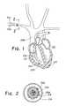
- FIG. 1is a partial cross-sectional view of a heart having an electrical pacemaker lead implanted therein;
- FIG. 2is a sectional view of a portion of the right subclavian vein illustrated in FIG. 1 , showing the electrical lead passing therethrough;
- FIG. 3is a side view of a cutter apparatus that may be utilized to prepare a pacemaker lead for removal
- FIG. 4is a front view of the cutter apparatus of FIG. 3 ;
- FIG. 5illustrates one embodiment of a gripping device according to the present invention, partially in section, shown pulling an implanted structure
- FIG. 5Aillustrates a knot drawn back to allow complementary tension to the insulation
- FIG. 6illustrates another embodiment of a gripping device
- FIGS. 6A and 6Billustrate alternative embodiments of a collar portion of the gripping device
- FIG. 7illustrates another embodiment of a cutter apparatus that may be used to prepare a lead targeted for removal
- FIGS. 8A to 8Cillustrate the use of a sleeve member for removing an implantable structure
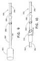
- FIG. 9is a variation of the embodiment of FIGS. 8A-8C , wherein the sleeve is provided with an extension handle;
- FIG. 10shows the embodiment of FIG. 9 , and also illustrates a dilator sheath for removing fibrotic tissue from the implanted structure.
- proximal and distalwill be used to describe the opposing axial ends of the device described, as well as the axial ends of various component features.
- proximalis used in its conventional sense to refer to the end of the device (or component thereof) that is closest to the operator during use of the device.
- distalis used in its conventional sense to refer to the end of the device (or component thereof) that is initially inserted into the patient, or that is closest to the patient.
- the present inventioncomprises a device for grasping and providing traction to an implanted elongated structure targeted for removal from a body vessel, such as an artery or a vein.
- the deviceis used for removing a cardiac pacemaker lead.
- a non-limiting list of other usesincludes removing other implanted elongated structures, such as defibrillator leads, other cardiac electrical leads, catheters, sheaths, cannulae and the like.
- the present inventioncomprises a method for removing an implanted elongated structure.
- the distal end of the structure targeted for removalWhen the implanted elongated structure targeted for removal is a cardiac pacemaker lead, the distal end of the structure will be located within the vascular system of the patient, and in particular, within a chamber of the patient's heart (such as in an atrium or ventricle of the heart). When the implanted elongated structure is a defibrillator lead, the distal end of the structure will be located either in or about the heart of the patient. The distal ends of other types of implanted elongated structures targeted for removal may not be and need not be near the heart.
- a cardiac pacemaker leadcomprises an inner core, comprising a cable or a coil, surrounded by a layer of insulating material.
- some pacemaker leadshave a lumen extending therethrough, while others (“lumenless” leads) do not.
- the inventive deviceis useful for pulling implanted leads having a lumen, as well as lumenless leads. The device is believed to have particular utility in removing lumenless leads, since there are many other removal devices presently available that may be used to remove leads having a lumen.
- the inventive device and methodWhen the inventive device and method is to be used for removal of a pacemaker or a defibrillator lead, those skilled in the art will appreciate that the lead should initially be severed from the connector prior to any attempts to remove the lead.
- the connectorhas a much larger diameter than the remainder of the lead, and only an unreasonably large dilator sheath could fit over the connector.
- a known technique for removing an implanted pacemaker leadinvolves advancing a two-part dilator sheath over the lead to break up fibrous adhesions that have grown between the interior of the vessel wall and the implanted device, and that are preventing easy withdrawal of the implanted device.
- the implanted deviceis bowed or cantilevered in any manner within the vessel, the dilator sheath cannot be readily advanced over the device.
- the structure of the inventive lead-pulling deviceallows for tensional forces to be applied longitudinally along the length of the lead body. This limits the bowing or cantilevering of the lead, such that a dilator sheath may be readily passed over the lead puller/lead interface without obstruction.
- FIG. 1Depicted in FIG. 1 is a partial cross-sectional view of the heart 215 of a patient.
- Heart 215is connected to a plurality of arteries and veins, such as the right subclavian vein 216 through which an electrical heart pacemaker lead 204 has been implanted.
- the leadpasses through the superior vena cava 208 and into the right ventricle 217 of the heart.
- the distal end of the leadincludes an electrode 220 for electrically stimulating the heart.
- the electrodeis secured to the apex of the right ventricle with a plurality of tines 207 , which in time, become securely attached to the ventricle wall by endothelial tissue forming around the heart lead tip.
- Some ventriclesare relatively smooth on the inside, but most have trabeculae amongst which the tines are secured into position.
- FIG. 2A sectional view of pacing lead 204 in right subclavian vein 216 is shown in FIG. 2 .
- pacing lead 204is encapsulated in fibrotic tissue 218 .
- Pacing lead 204is shown as a lumenless lead.
- leads having a lumenas well as leads fabricated from a “coiled” inner wire (conductor).
- lead 204comprises an interior braided cable 205 which mechanically and electrically connects the proximal connector to the electrode.
- the cableis covered by a layer of insulating material 206 .
- Insulating material 206typically comprises a hollow tube that surrounds the cable, and prevents fluid from making contact with the cable. Insulating material 206 is formed of a relatively flexible material well-known for such use, such as silicone or polyurethane.
- a gripping mechanism(as described hereinafter) is provided for engaging the pacemaker lead cable so that the lead can be removed from the body vessel.
- the gripping mechanismhas a compact profile, which allows the physician to use the smallest possible diameter dilator sheath for loosening the lead from the surrounding fibrotic tissue.
- the gripping mechanismcan be utilized to remove an implantable structure from a smaller diameter vessel when compared to a gripping device having a larger profile.
- the mechanismis structured such that it grips an exposed portion of the cable from which the insulating layer has previously been removed. Since the pacemaker lead typically comprises a hard interior cable portion and a softer outer insulating layer, it is desirable to utilize a cutter that cuts only through the insulating layer and not through the cable, so that the insulating layer can be removed from the underlying cable.
- FIG. 3illustrates a side view
- FIG. 4illustrates a front view of one example of a soft-tipped cutter 230 suitable for such use.
- Soft-tipped cutter 230is structured for cutting soft material in proximity to harder material, and to avoid or minimize damage to harder material which one does not intend to cut. During removal of the pacing lead, a portion of the soft insulating material 206 is therefore initially removed to expose the interior cable 205 .
- Soft-tipped cutter 230includes grasping handles 232 , 234 that are pivotable around a hinged connection 236 , for selectively opening and closing arms 238 , 240 .
- Cutting jaws 242 , 244are provided at the distal end of respective arms 238 , 240 . Jaws 242 , 244 are preferably V-shaped, as shown in FIG. 3 .
- jaws 242 , 244are formed of a material that is softer than that of the conductor portion of the electrical cable lead, but is harder than the insulating material. This arrangement allows cutter 230 to cut through the insulating layer 206 , but not through the conductor cable 205 .
- suitable materials for the jawsinclude aluminum, fiber glass, epoxy, and the like.
- the jawsare preferably arranged on arms 238 , 240 in an offset manner as best shown in the front view of FIG. 4 .
- arms 238 , 240are urged together in conventional fashion.
- the jawscut through the insulating material when they are urged together, but do not cut into the conductor cable.
- the cut portion of the insulating materialmay simply be peeled away in the proximal direction from the cut line to expose the underlying cable.
- the leadis cut such that at least a couple of inches of insulation can be removed from the exposed proximal end of the lead. Removal of the insulating material allows the use of a more compact gripping mechanism than could be used if the insulating material was left in place.
- cutter handles and the jawsmay be formed of the same composition, as long as care is taken to insure that the cutter cuts only through the insulating material, and not through the interior cable.
- the cutter handles and jawsmay be formed of the same material, and then the jaws may be subjected to a softening treatment.
- the entire cutter devicemay be formed of a metal or alloy, such as stainless steel 440C, and the jaws could be locally softened using conventional means, e.g., a laser beam.
- the jaws(cutter tips) are shown in FIGS. 3 and 4 as being mounted on scissors-type handles, other arrangements may be substituted.
- the jawsmay be provided on a vise-like tool, or mounted on a laparoscopic device.
- the jawsneed not each have the same configuration.
- one of the jawsmay be shaped like a wedge, with the opposing jaw having a flat surface.
- the jawsmay also be of different hardnesses.
- the cutterneed not even be provided with discrete jaws.
- the handles of a pair of scissors, where the handles overlapmay be locally softened to function as soft tips, or the handles may be made of soft materials.
- soft insertsmay be placed on otherwise hard cutting surfaces.
- FIG. 5A preferred embodiment of a gripping device 10 according to the present invention is shown in FIG. 5 .
- Gripping device 10includes a receiving portion, such as wire 12 , and a suitable capturing device, such as collar 20 .
- wire 12comprises an elongated wire structure folded back upon itself to comprise adjacent wire lengths 13 , 14 .
- wire lengths 13 , 14may be engaged by well-known means, such as by twisting, soldering, welding, and/or adhesion, to define en eyelet 16 .
- solder 19is applied to the terminal end of wire 12 at wire lengths 13 , 14 .
- knots, or suture-ties, 209are preferably tied on the lead near the location where the insulation has been cut.
- a sufficient number of knotsmay be tied such that the knot(s) will not pull into the insulation, but the number should not be so large as to cause difficulty when sliding a dilator sheath over the lead.
- FIG. 5Aillustrates a knot drawn back to allow complementary tension to the insulation. This arrangement may be used to limit the longitudinal compression of a lead insulating sheath caused by the advancing of the dilator sheath, which may otherwise result in snaking of the insulating sheath, and in undesirable friction or binding against the dilator sheath.
- wire 12is formed from stainless steel round wire, nickel-chromium round wire, or a nickel-titanium superelastic wire, and has a diameter of about 0.017 inch (0.43 mm)
- Collar 20is preferably fabricated from stainless steel or other metals or metal alloys by machining or by forming from a tube.
- collar 20may be formed from plastics or composite materials; however in this event it is advantageous to utilize stiff or filled plastics or composites in order to maintain the compactness of the sleeve.
- the inside diameter of collar 20is sized such that the respective wire high points 13 A, 14 A that define the eyelet are squeezed together as collar 20 is advanced in the distal direction toward the eyelet. This causes wire lengths 13 , 14 to bite on the entrapped cable end, thereby holding the cable end within the eyelet and preventing disengagement.
- a lead cable 205 of 0.012 inch (0.30 mm) diametermay be threaded through the eyelet.
- the diameter of optional reduced diameter collar portion 22is sized to prevent collar portion 22 from sliding over the eyelet 16 when cable end 205 is positioned in the eyelet, or alternatively, to permit collar portion 22 to slide over the eyelet only upon the application of a large amount of force to the collar. This feature prevents unintended over-advancing of the collar beyond the eyelet.
- reduced diameter portion 22has an opening of about 0.035 inch (0.89 mm). This allows free sliding of collar 20 along wire portion 12 until reduced diameter portion 22 reaches the entrapped lead. This provides the physician with a tactile feel as to when to stop advancing the collar.
- the size of the eyeletis about 0.1 inch (2.5 mm) wide and 0.8 inch (20 mm) long. With these dimensions, the eyelet is sufficiently large to facilitate threading of cable 205 through the eyelet.
- outer insulating layer 206 of pacemaker lead 204is cut and peeled away in the manner described above. Once the segment of insulating layer has been removed, a leading end of exposed cable 205 is threaded through eyelet 16 , as shown in FIG. 5 . Collar 20 is then urged in the direction of the arrow in FIG. 5 to compress the opposing wire portions 13 , 14 that define eyelet 16 around the cable as previously described.
- collar 20has a length of about 1 inch (2.54 cm), and an outer diameter not exceeding about 6 French (0.079 inch; 2 mm). Typically, the outer diameter may be about 0.06 inch (1.5 mm).
- collar 20may comprise a sheath several inches long or greater, with a single inside diameter throughout all or a substantial portion of the entire length. This increased length would facilitate containment of excess cable inside the sheath, and allow extension of the sheath over the proximal end of the lead insulation. Because of its length, it is preferred that the sheath be flexible in bending. For example, it may be fabricated from a plastic tubing, with optional braiding or coil for increased circumferential strength. Reduced collar portion 22 may also be omitted in this design.
- a conventional dilator sheathmay be slid over the lead puller and advanced into the patient to sever the fibrotic sheaths that have grown around the implanted pacemaker lead.
- the leadmay then pulled from the vessel by withdrawing it in the proximal direction through the dilator sheath. Due to the compact profile of the gripping device 10 , a smaller diameter dilator sheath may be utilized when compared to the use of a gripping device not having this profile, thereby minimizing trauma to the patient.
- FIG. 6Another embodiment of a gripping device 30 is shown in FIG. 6 .
- gripping device 30includes a wire 32 and a collar 40 as before. Adjacent wire lengths 33 , 34 , are aligned to define a terminal loop, which comprises eyelet 36 . The terminal portion of wire 32 is not twisted or otherwise engaged in the manner of gripping device 10 .
- Those skilled in the artwill appreciate that although this embodiment is satisfactory for many diameters of cable 205 , wire 32 and/or collar 40 , it may not provide the type of wedging action that is obtained in the embodiment of FIG. 5 when the collar is advanced in the direction of the arrow. Accordingly, with some diameters of cable, wire and collar, the lead may not be as securely locked when compared to the gripping ability of the device of FIG. 5 . However, even though the embodiment of FIG. 5 may provide better gripping of the cable end, gripping may add an element of stress to the cable. This may reduce its tensile pull strength somewhat when compared to the embodiment of FIG. 6 .
- the collarmay be provided with more than one lumen, as illustrated in FIGS. 6A and 6B .
- FIG. 6Aillustrates a collar 40 A having dual parallel lumens 250 , 251 .
- FIG. 6Balso illustrates a collar 40 B having dual lumens 252 , 253 .
- lumens 252 , 253are angled or wedged such that the lumens are spaced a greater distance at the proximal end of the collar and a smaller distance at the distal end.
- one end of a wireis threaded through each of the lumens such that a loop extends distal to the collar, as shown in the embodiment of FIG. 6 .
- Cable end 205is threaded through the loop as before, and the wire ends may be pulled in the proximal direction such that the cable end is captured and held by the wire against distal face 249 , 254 of respective collars 40 A and 40 B.
- FIG. 7illustrates another type of soft-tipped cutter 330 that may be used to prepare an exposed end of the lead targeted for removal.
- Soft-tipped cutter 330may include handles 332 , 334 , hinge 336 , arms 338 , 340 and jaws 342 , 344 .
- the featuresare generally similar to the corresponding features of cutter 230 as illustrated in FIGS. 3 and 4 .
- cutter 330is also provided with a second set of jaws, in this case, crimping jaws 346 , 348 .
- Soft-tipped cutter 330may be advantageously used with an alternative embodiment of a gripping device illustrated in FIGS. 8A-8C .
- the proximal end of a pacemaker lead 204is initially cut, and insulation 206 is removed to expose a portion of the cable 205 as before.
- a sleeve 350is then provided over the cut and bared portion of the cable.
- FIG. 8Aillustrates the sleeve 350
- FIG. 8Billustrates the cut and bared cable 204 .
- sleeve 350has a generally cylindrical profile with an inner diameter that exceeds the outer diameter of cable 205 by only a nominal amount, such that sleeve 350 is insertable over cable 205 as illustrated in FIG. 8C .
- jaws 346 , 348 of cutter 330comprise a crimping mechanism that may be used to crimp sleeve 350 onto cable portion 205 .
- the broken lines of FIG. 8Cillustrate the crimped profile of the sleeve. Use of a crimped sleeve eliminates any necessity to place a knot at the proximal end of the lead, and prevents lead extension devices from sliding proximally off the lead or other device targeted for removal.
- the sleeve 350can in theory have any diameter, but the preferred dimension is one that has an outer diameter after engagement of less than 0.092 inch (2.4 mm; 7 French). In this manner, the sleeve can be drawn through a dilation sheath having an inner diameter of 7 French.
- Sleeve 350can have a consistent wall thickness across in longitudinal length, or it may have a varied wall thickness to allow for adequate sleeve distortion that may be required to form a locking engagement. Alternately, a crimping pattern may include multiple sleeve distortions following multiple vectors.
- FIG. 9A variation of the embodiment of FIGS. 8A-8C is shown in FIG. 9 .
- crimped sleeve 350is provided with an extension handle 360 that extends in the proximal direction.
- the extension handlecan include one or more elongated wires that are attachable to and extend in the proximal direction from the sleeve.
- extension handle 360comprises two elongated wires 361 , 362 that are attachable to and extend from sleeve 350 .
- the extension handlecan be used to apply direct traction to the targeted lead, and as a guide for passage of a conventional dilator sheath.
- FIG. 9A variation of the embodiment of FIGS. 8A-8C is shown in FIG. 9 .
- crimped sleeve 350is provided with an extension handle 360 that extends in the proximal direction.
- the extension handlecan include one or more elongated wires that are attachable to and extend in the proximal direction from the slee
- FIG. 10illustrates the use of dilator sheath 370 in combination with sleeve 350 and extension wires 361 , 362 .
- the direction of movement of dilator sheath 370 in the vessel to cut fibrotic tissueis shown by the arrow in the figure.
- the gripping devicehas been described herein for use with conventional pacemaker leads having a single cable or coil surrounded by the insulating material.
- the principles of the present inventionare also applicable to removal of a bi-polar lead, such as a bi-polar pacing lead.
- a bi-polar leadsuch as a bi-polar pacing lead.
- bi-polar leadsan additional conductor coil surrounds the cable, with an insulating material between the conductor coil and the cable. In this instance, the insulating material between the inner cable and the coil is also cut and removed. For best results, the coil is stretched out and as much insulation as possible is removed.
- the present inventionhas been described as a gripping device, and as methods for removing an elongated structure from a patient using various embodiments of the inventive gripping device.
- the inventionalso includes a kit for use in removing a previously implanted elongated structure from a patient.
Landscapes
- Health & Medical Sciences (AREA)
- Heart & Thoracic Surgery (AREA)
- Cardiology (AREA)
- Nuclear Medicine, Radiotherapy & Molecular Imaging (AREA)
- Engineering & Computer Science (AREA)
- Biomedical Technology (AREA)
- Vascular Medicine (AREA)
- Radiology & Medical Imaging (AREA)
- Life Sciences & Earth Sciences (AREA)
- Animal Behavior & Ethology (AREA)
- General Health & Medical Sciences (AREA)
- Public Health (AREA)
- Veterinary Medicine (AREA)
- Electrotherapy Devices (AREA)
- Surgical Instruments (AREA)
Abstract
Description
Claims (15)
Priority Applications (1)
| Application Number | Priority Date | Filing Date | Title |
|---|---|---|---|
| US11/704,852US8128636B2 (en) | 2006-02-13 | 2007-02-09 | Device and method for removing lumenless leads |
Applications Claiming Priority (2)
| Application Number | Priority Date | Filing Date | Title |
|---|---|---|---|
| US77314006P | 2006-02-13 | 2006-02-13 | |
| US11/704,852US8128636B2 (en) | 2006-02-13 | 2007-02-09 | Device and method for removing lumenless leads |
Publications (2)
| Publication Number | Publication Date |
|---|---|
| US20070191919A1 US20070191919A1 (en) | 2007-08-16 |
| US8128636B2true US8128636B2 (en) | 2012-03-06 |
Family
ID=38335640
Family Applications (1)
| Application Number | Title | Priority Date | Filing Date |
|---|---|---|---|
| US11/704,852Active2029-03-01US8128636B2 (en) | 2006-02-13 | 2007-02-09 | Device and method for removing lumenless leads |
Country Status (3)
| Country | Link |
|---|---|
| US (1) | US8128636B2 (en) |
| EP (1) | EP1984072B1 (en) |
| WO (1) | WO2007100474A2 (en) |
Cited By (27)
| Publication number | Priority date | Publication date | Assignee | Title |
|---|---|---|---|---|
| US8961551B2 (en) | 2006-12-22 | 2015-02-24 | The Spectranetics Corporation | Retractable separating systems and methods |
| US9028520B2 (en) | 2006-12-22 | 2015-05-12 | The Spectranetics Corporation | Tissue separating systems and methods |
| US9283040B2 (en) | 2013-03-13 | 2016-03-15 | The Spectranetics Corporation | Device and method of ablative cutting with helical tip |
| US9291663B2 (en) | 2013-03-13 | 2016-03-22 | The Spectranetics Corporation | Alarm for lead insulation abnormality |
| US9413896B2 (en) | 2012-09-14 | 2016-08-09 | The Spectranetics Corporation | Tissue slitting methods and systems |
| USD765243S1 (en) | 2015-02-20 | 2016-08-30 | The Spectranetics Corporation | Medical device handle |
| US9456872B2 (en) | 2013-03-13 | 2016-10-04 | The Spectranetics Corporation | Laser ablation catheter |
| USD770616S1 (en) | 2015-02-20 | 2016-11-01 | The Spectranetics Corporation | Medical device handle |
| US9603618B2 (en) | 2013-03-15 | 2017-03-28 | The Spectranetics Corporation | Medical device for removing an implanted object |
| US9668765B2 (en) | 2013-03-15 | 2017-06-06 | The Spectranetics Corporation | Retractable blade for lead removal device |
| US9731113B2 (en) | 2014-12-30 | 2017-08-15 | The Spectranetics Corporation | Collapsing coil coupling for lead extension and extraction |
| US9884184B2 (en) | 2014-12-30 | 2018-02-06 | The Spectranetics Corporation | Wire hook coupling for lead extension and extraction |
| US9883885B2 (en) | 2013-03-13 | 2018-02-06 | The Spectranetics Corporation | System and method of ablative cutting and pulsed vacuum aspiration |
| US9918729B2 (en) | 2009-09-14 | 2018-03-20 | The Spectranetics Corporation | Snaring systems and methods |
| US9925366B2 (en) | 2013-03-15 | 2018-03-27 | The Spectranetics Corporation | Surgical instrument for removing an implanted object |
| US9980743B2 (en) | 2013-03-15 | 2018-05-29 | The Spectranetics Corporation | Medical device for removing an implanted object using laser cut hypotubes |
| US10105533B2 (en) | 2014-12-30 | 2018-10-23 | The Spectranetics Corporation | Multi-loop coupling for lead extension and extraction |
| US10136913B2 (en) | 2013-03-15 | 2018-11-27 | The Spectranetics Corporation | Multiple configuration surgical cutting device |
| US10383691B2 (en) | 2013-03-13 | 2019-08-20 | The Spectranetics Corporation | Last catheter with helical internal lumen |
| US10405924B2 (en) | 2014-05-30 | 2019-09-10 | The Spectranetics Corporation | System and method of ablative cutting and vacuum aspiration through primary orifice and auxiliary side port |
| US10448999B2 (en) | 2013-03-15 | 2019-10-22 | The Spectranetics Corporation | Surgical instrument for removing an implanted object |
| US10835279B2 (en) | 2013-03-14 | 2020-11-17 | Spectranetics Llc | Distal end supported tissue slitting apparatus |
| US10842532B2 (en) | 2013-03-15 | 2020-11-24 | Spectranetics Llc | Medical device for removing an implanted object |
| US10952785B2 (en) | 2016-08-01 | 2021-03-23 | Medtronic Advanced Energy, Llc | Device for medical lead extraction |
| US11357977B2 (en) | 2014-12-30 | 2022-06-14 | Spectranetics Llc | Expanding coil coupling for lead extension and extraction |
| US11883089B2 (en) | 2016-11-14 | 2024-01-30 | Medtronic, Inc. | Controlled optical properties vitreous enamel composition for electrosurgical tool |
| US12053203B2 (en) | 2014-03-03 | 2024-08-06 | Spectranetics, Llc | Multiple configuration surgical cutting device |
Families Citing this family (5)
| Publication number | Priority date | Publication date | Assignee | Title |
|---|---|---|---|---|
| US20100222787A1 (en)* | 2009-03-02 | 2010-09-02 | Cook Vascular Incorporated | Tension control device |
| JP6692920B2 (en)* | 2016-03-31 | 2020-05-13 | カーディアック ペースメイカーズ, インコーポレイテッド | Implantable medical device configured for deployment within a patient's heart chamber and implantable medical device configured for deployment within a patient's body |
| US10960216B2 (en)* | 2016-03-31 | 2021-03-30 | Cardiac Pacemakers, Inc. | Extraction devices configued to extract chronically implanted medical devices |
| US10828499B2 (en)* | 2017-05-05 | 2020-11-10 | Pacesetter, Inc. | Implant delivery and retrieval systems and methods |
| CN115996686B (en)* | 2020-09-11 | 2024-03-22 | 巴德外周血管股份有限公司 | Medical device comprising expandable muscle polymer |
Citations (93)
| Publication number | Priority date | Publication date | Assignee | Title |
|---|---|---|---|---|
| US507751A (en) | 1893-10-31 | Half to charles t | ||
| US3118159A (en) | 1961-10-13 | 1964-01-21 | Karl J Kollmann | Sewer snake |
| US3128652A (en) | 1962-05-17 | 1964-04-14 | Ideal Ind | Adjustable wire stripper |
| US3243755A (en) | 1964-03-16 | 1966-03-29 | Gen Electric | Electrical connector |
| US3516412A (en) | 1965-08-16 | 1970-06-23 | Electro Catheter Corp | Bipolar electrode having irregularity at inserting end thereof and method of insertion |
| US3757375A (en) | 1971-08-18 | 1973-09-11 | M Strom | Obstruction removal apparatus |
| US3841308A (en) | 1973-10-15 | 1974-10-15 | Medical Evaluation Devices & I | Distally valved catheter device |
| US3906938A (en) | 1974-09-03 | 1975-09-23 | Lake Region Manufacturing Comp | Coil spring wire guide |
| US4000745A (en) | 1968-08-05 | 1977-01-04 | Goldberg Edward M | Electrical leads for cardiac stimulators and related methods and means |
| US4011869A (en) | 1975-08-01 | 1977-03-15 | David Kopf Instruments | Tubular cutting instrument |
| US4040413A (en) | 1974-07-18 | 1977-08-09 | Fuji Photo Optical Co. Ltd. | Endoscope |
| US4306562A (en) | 1978-12-01 | 1981-12-22 | Cook, Inc. | Tear apart cannula |
| US4466690A (en) | 1981-06-24 | 1984-08-21 | Peter Osypka | Connector for the conductors of implanted medical devices |
| US4471777A (en) | 1983-03-30 | 1984-09-18 | Mccorkle Jr Charles E | Endocardial lead extraction apparatus and method |
| US4493329A (en) | 1982-08-19 | 1985-01-15 | Lynn Crawford | Implantable electrode having different stiffening and curvature maintaining characteristics along its length |
| US4498482A (en) | 1979-12-13 | 1985-02-12 | Medtronic, Inc. | Transvenous pacing lead having improved stylet |
| US4541681A (en) | 1983-05-04 | 1985-09-17 | Cordis Corporation | Electrical connection of wire conductor(s) to a terminal pin in an electrode assembly of a pacing lead |
| US4574800A (en) | 1984-12-07 | 1986-03-11 | Cordis Corporation | Implanted lead extractor |
| US4576162A (en) | 1983-03-30 | 1986-03-18 | Mccorkle Charles E | Apparatus and method for separation of scar tissue in venous pathway |
| US4581025A (en) | 1983-11-14 | 1986-04-08 | Cook Incorporated | Sheath |
| US4582056A (en) | 1983-03-30 | 1986-04-15 | Mccorkle Jr Charles E | Endocardial lead extraction apparatus and method |
| US4621636A (en) | 1979-07-23 | 1986-11-11 | Fogarty Thomas J | Endarterectomy method and apparatus |
| US4706671A (en) | 1985-05-02 | 1987-11-17 | Weinrib Harry P | Catheter with coiled tip |
| US4732154A (en) | 1984-05-14 | 1988-03-22 | Surgical Systems & Instruments, Inc. | Rotary catheter system |
| US4762130A (en) | 1987-01-15 | 1988-08-09 | Thomas J. Fogarty | Catheter with corkscrew-like balloon |
| US4762128A (en) | 1986-12-09 | 1988-08-09 | Advanced Surgical Intervention, Inc. | Method and apparatus for treating hypertrophy of the prostate gland |
| US4773432A (en) | 1987-02-09 | 1988-09-27 | Schneider-Shiley (Usa) Inc. | Bail-out catheter |
| US4791939A (en) | 1985-06-27 | 1988-12-20 | Nivarox-Far S.A. | Stylet for use with an implantable pacing lead |
| US4796642A (en) | 1987-12-28 | 1989-01-10 | Cordis Leads, Inc. | Pacing lead stylet |
| US4834090A (en) | 1987-03-02 | 1989-05-30 | Moore J Paul | Suture boot |
| US4848342A (en) | 1985-09-13 | 1989-07-18 | Martin Kaltenbach | Dilation catheter |
| US4886500A (en) | 1988-11-07 | 1989-12-12 | Lazarus Harrison M | External guide wire |
| US4886496A (en) | 1988-02-04 | 1989-12-12 | Conoscenti Craig S | Bronchoscopic balloon tipped catheter and method of making the same |
| US4943289A (en) | 1989-05-03 | 1990-07-24 | Cook Pacemaker Corporation | Apparatus for removing an elongated structure implanted in biological tissue |
| EP0385920A2 (en) | 1989-03-03 | 1990-09-05 | Thomas J. Fogarty | Variable diameter sheath apparatus for use in body passages |
| US4988347A (en) | 1988-11-09 | 1991-01-29 | Cook Pacemaker Corporation | Method and apparatus for separating a coiled structure from biological tissue |
| US5011482A (en) | 1989-01-17 | 1991-04-30 | Cook Pacemaker Corporation | Apparatus for removing an elongated structure implanted in biological tissue |
| US5013310A (en) | 1988-11-09 | 1991-05-07 | Cook Pacemaker Corporation | Method and apparatus for removing an implanted pacemaker lead |
| US5061257A (en) | 1990-04-30 | 1991-10-29 | Cordis Corporation | Apertured, reinforced catheter |
| US5066285A (en) | 1990-01-26 | 1991-11-19 | Cordis Corporation | Catheter introducer sheath made of expanded polytetrafluoroethylene |
| US5066772A (en) | 1987-12-17 | 1991-11-19 | Allied-Signal Inc. | Medical devices fabricated totally or in part from copolymers of recurring units derived from cyclic carbonates and lactides |
| US5067489A (en) | 1988-08-16 | 1991-11-26 | Flexmedics Corporation | Flexible guide with safety tip |
| US5098374A (en) | 1987-09-02 | 1992-03-24 | Engineers & Doctors A/A | Device for the placing of a partial catheter in a body cavity |
| US5098440A (en)* | 1990-08-14 | 1992-03-24 | Cordis Corporation | Object retrieval method and apparatus |
| US5106368A (en) | 1990-04-20 | 1992-04-21 | Cook Incorporated | Collapsible lumen catheter for extracorporeal treatment |
| US5108368A (en) | 1990-01-04 | 1992-04-28 | Pilot Cardiovascular System, Inc. | Steerable medical device |
| US5112299A (en) | 1989-10-25 | 1992-05-12 | Hall Surgical Division Of Zimmer, Inc. | Arthroscopic surgical apparatus and method |
| US5171222A (en) | 1988-03-10 | 1992-12-15 | Scimed Life Systems, Inc. | Interlocking peel-away dilation catheter |
| US5190528A (en) | 1990-10-19 | 1993-03-02 | Boston University | Percutaneous transseptal left atrial cannulation system |
| US5207683A (en) | 1988-11-09 | 1993-05-04 | Cook Pacemaker Corporation | Apparatus for removing an elongated structure implanted in biological tissue |
| US5221255A (en) | 1990-01-10 | 1993-06-22 | Mahurkar Sakharam D | Reinforced multiple lumen catheter |
| US5231996A (en) | 1992-01-28 | 1993-08-03 | Medtronic, Inc. | Removable endocardial lead |
| US5234437A (en) | 1991-12-12 | 1993-08-10 | Target Therapeutics, Inc. | Detachable pusher-vasoocclusion coil assembly with threaded coupling |
| US5250038A (en) | 1992-10-09 | 1993-10-05 | Cook Incorporated | Multiple lumen vascular access introducer sheath |
| US5329923A (en) | 1991-02-15 | 1994-07-19 | Lundquist Ingemar H | Torquable catheter |
| US5342371A (en) | 1993-11-24 | 1994-08-30 | Cook Incorporated | Helical surgical snare |
| US5346497A (en) | 1992-07-15 | 1994-09-13 | The University Of Miami | Surgical cutting head with asymmetrical cutting notch |
| US5387219A (en)* | 1992-09-23 | 1995-02-07 | Target Therapeutics | Medical retrieval snare with coil wrapped loop |
| US5409469A (en) | 1993-11-04 | 1995-04-25 | Medtronic, Inc. | Introducer system having kink resistant splittable sheath |
| US5415639A (en) | 1993-04-08 | 1995-05-16 | Scimed Life Systems, Inc. | Sheath and method for intravascular treatment |
| US5454790A (en) | 1994-05-09 | 1995-10-03 | Innerdyne, Inc. | Method and apparatus for catheterization access |
| US5522819A (en)* | 1994-05-12 | 1996-06-04 | Target Therapeutics, Inc. | Dual coil medical retrieval device |
| US5533968A (en) | 1991-05-15 | 1996-07-09 | Advanced Cardiovascular Systems, Inc. | Low profile catheter with expandable outer tubular member |
| US5549615A (en) | 1989-11-11 | 1996-08-27 | Vascomed Institut Fur Kathetertechnologie Gmbh | Method and apparatus for extracting pacemaker electrodes embedded in the heart |
| US5562678A (en)* | 1995-06-02 | 1996-10-08 | Cook Pacemaker Corporation | Needle's eye snare |
| US5562620A (en) | 1994-04-01 | 1996-10-08 | Localmed, Inc. | Perfusion shunt device having non-distensible pouch for receiving angioplasty balloon |
| US5618267A (en) | 1994-07-28 | 1997-04-08 | Palestrant; Aubrey M. | Method for establishing collapsible infusion conduit |
| US5628754A (en) | 1995-08-01 | 1997-05-13 | Medtronic, Inc. | Stent delivery guide catheter |
| US5645533A (en) | 1991-07-05 | 1997-07-08 | Scimed Life Systems, Inc. | Apparatus and method for performing an intravascular procedure and exchanging an intravascular device |
| US5697936A (en) | 1988-11-10 | 1997-12-16 | Cook Pacemaker Corporation | Device for removing an elongated structure implanted in biological tissue |
| US5725512A (en) | 1993-11-03 | 1998-03-10 | Daig Corporation | Guilding introducer system for use in the left atrium |
| US5725551A (en) | 1993-07-26 | 1998-03-10 | Myers; Gene | Method and apparatus for arteriotomy closure |
| US5976107A (en) | 1991-07-05 | 1999-11-02 | Scimed Life Systems. Inc. | Catheter having extendable guide wire lumen |
| US6007517A (en) | 1996-08-19 | 1999-12-28 | Anderson; R. David | Rapid exchange/perfusion angioplasty catheter |
| US6027475A (en) | 1991-05-15 | 2000-02-22 | Advanced Cardiovascular Systems, Inc. | Catheter shaft with an oblong transverse cross-section |
| US6033402A (en) | 1998-09-28 | 2000-03-07 | Irvine Biomedical, Inc. | Ablation device for lead extraction and methods thereof |
| US6136005A (en) | 1988-11-09 | 2000-10-24 | Cook Pacemaker Corporation | Apparatus for removing a coiled structure implanted in biological tissue, having expandable means including a laterally deflectable member |
| US6167315A (en) | 1999-04-05 | 2000-12-26 | Spectranetics Corporation | Lead locking device and method |
| US6190353B1 (en) | 1995-10-13 | 2001-02-20 | Transvascular, Inc. | Methods and apparatus for bypassing arterial obstructions and/or performing other transvascular procedures |
| US6190349B1 (en) | 1997-08-06 | 2001-02-20 | Hemocleanse, Inc. | Splittable multiple catheter assembly and methods for inserting the same |
| US6264671B1 (en) | 1999-11-15 | 2001-07-24 | Advanced Cardiovascular Systems, Inc. | Stent delivery catheter and method of use |
| US6315781B1 (en) | 1997-11-03 | 2001-11-13 | VASCOMED INSTITUTE FüR KATHETERTECHNOLOGIE GMBH | Device and method for extracting an object featuring a longitudinal inner lumen from its anchoring in a body |
| US6350271B1 (en) | 1999-05-17 | 2002-02-26 | Micrus Corporation | Clot retrieval device |
| US6358256B1 (en) | 1999-06-24 | 2002-03-19 | Vascomed Institut Fuer Kathetertechnologie Gmbh | Apparatus for pulling out an object, having an elongated inner lumen, from its anchorage in a body |
| US6361541B1 (en) | 1998-07-17 | 2002-03-26 | The University Of Iowa Research Foundation | Surgical instrument for extracting tissue ingrowth from a permeable member of an implanted catheter |
| US6379319B1 (en) | 1996-10-11 | 2002-04-30 | Transvascular, Inc. | Systems and methods for directing and snaring guidewires |
| US6394978B1 (en) | 2000-08-09 | 2002-05-28 | Advanced Cardiovascular Systems, Inc. | Interventional procedure expandable balloon expansion enabling system and method |
| US20020077686A1 (en) | 1998-06-12 | 2002-06-20 | Cardiac Pacemakers, Inc. | Modified guidewire for left ventricular access lead |
| US6409863B1 (en) | 2000-06-12 | 2002-06-25 | Scimed Life Systems, Inc. | Methods of fabricating a catheter shaft having one or more guidewire ports |
| US6419674B1 (en) | 1996-11-27 | 2002-07-16 | Cook Vascular Incorporated | Radio frequency dilator sheath |
| US6544270B1 (en) | 2000-09-14 | 2003-04-08 | Cardiac Pacemakers, Inc. | Multi-lumen cardiac catheter and system |
| US6562049B1 (en) | 2000-03-01 | 2003-05-13 | Cook Vascular Incorporated | Medical introducer apparatus |
| US6695858B1 (en) | 1998-02-10 | 2004-02-24 | Artemis Medical, Inc. | Medical device and methods for use |
Family Cites Families (3)
| Publication number | Priority date | Publication date | Assignee | Title |
|---|---|---|---|---|
| US5507751A (en) | 1988-11-09 | 1996-04-16 | Cook Pacemaker Corporation | Locally flexible dilator sheath |
| US6342062B1 (en)* | 1998-09-24 | 2002-01-29 | Scimed Life Systems, Inc. | Retrieval devices for vena cava filter |
| WO2004069290A2 (en)* | 2003-01-31 | 2004-08-19 | Cordis Corporation | Filter retrieval catheter system, and methods |
- 2007
- 2007-02-09WOPCT/US2007/003585patent/WO2007100474A2/enactiveApplication Filing
- 2007-02-09EPEP07750422.3Apatent/EP1984072B1/enactiveActive
- 2007-02-09USUS11/704,852patent/US8128636B2/enactiveActive
Patent Citations (95)
| Publication number | Priority date | Publication date | Assignee | Title |
|---|---|---|---|---|
| US507751A (en) | 1893-10-31 | Half to charles t | ||
| US3118159A (en) | 1961-10-13 | 1964-01-21 | Karl J Kollmann | Sewer snake |
| US3128652A (en) | 1962-05-17 | 1964-04-14 | Ideal Ind | Adjustable wire stripper |
| US3243755A (en) | 1964-03-16 | 1966-03-29 | Gen Electric | Electrical connector |
| US3516412A (en) | 1965-08-16 | 1970-06-23 | Electro Catheter Corp | Bipolar electrode having irregularity at inserting end thereof and method of insertion |
| US4000745A (en) | 1968-08-05 | 1977-01-04 | Goldberg Edward M | Electrical leads for cardiac stimulators and related methods and means |
| US3757375A (en) | 1971-08-18 | 1973-09-11 | M Strom | Obstruction removal apparatus |
| US3841308A (en) | 1973-10-15 | 1974-10-15 | Medical Evaluation Devices & I | Distally valved catheter device |
| US4040413A (en) | 1974-07-18 | 1977-08-09 | Fuji Photo Optical Co. Ltd. | Endoscope |
| US3906938A (en) | 1974-09-03 | 1975-09-23 | Lake Region Manufacturing Comp | Coil spring wire guide |
| US4011869A (en) | 1975-08-01 | 1977-03-15 | David Kopf Instruments | Tubular cutting instrument |
| US4306562A (en) | 1978-12-01 | 1981-12-22 | Cook, Inc. | Tear apart cannula |
| US4621636A (en) | 1979-07-23 | 1986-11-11 | Fogarty Thomas J | Endarterectomy method and apparatus |
| US4498482A (en) | 1979-12-13 | 1985-02-12 | Medtronic, Inc. | Transvenous pacing lead having improved stylet |
| US4466690A (en) | 1981-06-24 | 1984-08-21 | Peter Osypka | Connector for the conductors of implanted medical devices |
| US4493329A (en) | 1982-08-19 | 1985-01-15 | Lynn Crawford | Implantable electrode having different stiffening and curvature maintaining characteristics along its length |
| US4582056A (en) | 1983-03-30 | 1986-04-15 | Mccorkle Jr Charles E | Endocardial lead extraction apparatus and method |
| US4576162A (en) | 1983-03-30 | 1986-03-18 | Mccorkle Charles E | Apparatus and method for separation of scar tissue in venous pathway |
| US4471777A (en) | 1983-03-30 | 1984-09-18 | Mccorkle Jr Charles E | Endocardial lead extraction apparatus and method |
| US4541681A (en) | 1983-05-04 | 1985-09-17 | Cordis Corporation | Electrical connection of wire conductor(s) to a terminal pin in an electrode assembly of a pacing lead |
| US4581025A (en) | 1983-11-14 | 1986-04-08 | Cook Incorporated | Sheath |
| US4732154A (en) | 1984-05-14 | 1988-03-22 | Surgical Systems & Instruments, Inc. | Rotary catheter system |
| US4574800A (en) | 1984-12-07 | 1986-03-11 | Cordis Corporation | Implanted lead extractor |
| US4706671A (en) | 1985-05-02 | 1987-11-17 | Weinrib Harry P | Catheter with coiled tip |
| US4791939A (en) | 1985-06-27 | 1988-12-20 | Nivarox-Far S.A. | Stylet for use with an implantable pacing lead |
| US4848342A (en) | 1985-09-13 | 1989-07-18 | Martin Kaltenbach | Dilation catheter |
| US4762128A (en) | 1986-12-09 | 1988-08-09 | Advanced Surgical Intervention, Inc. | Method and apparatus for treating hypertrophy of the prostate gland |
| US4762130A (en) | 1987-01-15 | 1988-08-09 | Thomas J. Fogarty | Catheter with corkscrew-like balloon |
| US4773432A (en) | 1987-02-09 | 1988-09-27 | Schneider-Shiley (Usa) Inc. | Bail-out catheter |
| US4834090A (en) | 1987-03-02 | 1989-05-30 | Moore J Paul | Suture boot |
| US5098374A (en) | 1987-09-02 | 1992-03-24 | Engineers & Doctors A/A | Device for the placing of a partial catheter in a body cavity |
| US5066772A (en) | 1987-12-17 | 1991-11-19 | Allied-Signal Inc. | Medical devices fabricated totally or in part from copolymers of recurring units derived from cyclic carbonates and lactides |
| US4796642A (en) | 1987-12-28 | 1989-01-10 | Cordis Leads, Inc. | Pacing lead stylet |
| US4886496A (en) | 1988-02-04 | 1989-12-12 | Conoscenti Craig S | Bronchoscopic balloon tipped catheter and method of making the same |
| US5171222A (en) | 1988-03-10 | 1992-12-15 | Scimed Life Systems, Inc. | Interlocking peel-away dilation catheter |
| US5067489A (en) | 1988-08-16 | 1991-11-26 | Flexmedics Corporation | Flexible guide with safety tip |
| US4886500A (en) | 1988-11-07 | 1989-12-12 | Lazarus Harrison M | External guide wire |
| US6136005A (en) | 1988-11-09 | 2000-10-24 | Cook Pacemaker Corporation | Apparatus for removing a coiled structure implanted in biological tissue, having expandable means including a laterally deflectable member |
| US4988347A (en) | 1988-11-09 | 1991-01-29 | Cook Pacemaker Corporation | Method and apparatus for separating a coiled structure from biological tissue |
| US5632749A (en) | 1988-11-09 | 1997-05-27 | Cook Pacemaker Corporation | Apparatus for removing an elongated structure implanted in biological tissue |
| US5013310A (en) | 1988-11-09 | 1991-05-07 | Cook Pacemaker Corporation | Method and apparatus for removing an implanted pacemaker lead |
| US5207683A (en) | 1988-11-09 | 1993-05-04 | Cook Pacemaker Corporation | Apparatus for removing an elongated structure implanted in biological tissue |
| US5697936A (en) | 1988-11-10 | 1997-12-16 | Cook Pacemaker Corporation | Device for removing an elongated structure implanted in biological tissue |
| US5011482A (en) | 1989-01-17 | 1991-04-30 | Cook Pacemaker Corporation | Apparatus for removing an elongated structure implanted in biological tissue |
| EP0385920A2 (en) | 1989-03-03 | 1990-09-05 | Thomas J. Fogarty | Variable diameter sheath apparatus for use in body passages |
| US4943289A (en) | 1989-05-03 | 1990-07-24 | Cook Pacemaker Corporation | Apparatus for removing an elongated structure implanted in biological tissue |
| US5112299A (en) | 1989-10-25 | 1992-05-12 | Hall Surgical Division Of Zimmer, Inc. | Arthroscopic surgical apparatus and method |
| US5549615A (en) | 1989-11-11 | 1996-08-27 | Vascomed Institut Fur Kathetertechnologie Gmbh | Method and apparatus for extracting pacemaker electrodes embedded in the heart |
| US5108368A (en) | 1990-01-04 | 1992-04-28 | Pilot Cardiovascular System, Inc. | Steerable medical device |
| US5221255A (en) | 1990-01-10 | 1993-06-22 | Mahurkar Sakharam D | Reinforced multiple lumen catheter |
| US5066285A (en) | 1990-01-26 | 1991-11-19 | Cordis Corporation | Catheter introducer sheath made of expanded polytetrafluoroethylene |
| US5106368A (en) | 1990-04-20 | 1992-04-21 | Cook Incorporated | Collapsible lumen catheter for extracorporeal treatment |
| US5061257A (en) | 1990-04-30 | 1991-10-29 | Cordis Corporation | Apertured, reinforced catheter |
| US5098440A (en)* | 1990-08-14 | 1992-03-24 | Cordis Corporation | Object retrieval method and apparatus |
| US5190528A (en) | 1990-10-19 | 1993-03-02 | Boston University | Percutaneous transseptal left atrial cannulation system |
| US5329923A (en) | 1991-02-15 | 1994-07-19 | Lundquist Ingemar H | Torquable catheter |
| US6027475A (en) | 1991-05-15 | 2000-02-22 | Advanced Cardiovascular Systems, Inc. | Catheter shaft with an oblong transverse cross-section |
| US5533968A (en) | 1991-05-15 | 1996-07-09 | Advanced Cardiovascular Systems, Inc. | Low profile catheter with expandable outer tubular member |
| US5976107A (en) | 1991-07-05 | 1999-11-02 | Scimed Life Systems. Inc. | Catheter having extendable guide wire lumen |
| US5645533A (en) | 1991-07-05 | 1997-07-08 | Scimed Life Systems, Inc. | Apparatus and method for performing an intravascular procedure and exchanging an intravascular device |
| US5234437A (en) | 1991-12-12 | 1993-08-10 | Target Therapeutics, Inc. | Detachable pusher-vasoocclusion coil assembly with threaded coupling |
| US5231996A (en) | 1992-01-28 | 1993-08-03 | Medtronic, Inc. | Removable endocardial lead |
| US5346497A (en) | 1992-07-15 | 1994-09-13 | The University Of Miami | Surgical cutting head with asymmetrical cutting notch |
| US5387219A (en)* | 1992-09-23 | 1995-02-07 | Target Therapeutics | Medical retrieval snare with coil wrapped loop |
| US5250038A (en) | 1992-10-09 | 1993-10-05 | Cook Incorporated | Multiple lumen vascular access introducer sheath |
| US5415639A (en) | 1993-04-08 | 1995-05-16 | Scimed Life Systems, Inc. | Sheath and method for intravascular treatment |
| US5725551A (en) | 1993-07-26 | 1998-03-10 | Myers; Gene | Method and apparatus for arteriotomy closure |
| US5725512A (en) | 1993-11-03 | 1998-03-10 | Daig Corporation | Guilding introducer system for use in the left atrium |
| US5409469A (en) | 1993-11-04 | 1995-04-25 | Medtronic, Inc. | Introducer system having kink resistant splittable sheath |
| US5342371A (en) | 1993-11-24 | 1994-08-30 | Cook Incorporated | Helical surgical snare |
| US5562620A (en) | 1994-04-01 | 1996-10-08 | Localmed, Inc. | Perfusion shunt device having non-distensible pouch for receiving angioplasty balloon |
| US5454790A (en) | 1994-05-09 | 1995-10-03 | Innerdyne, Inc. | Method and apparatus for catheterization access |
| US5522819A (en)* | 1994-05-12 | 1996-06-04 | Target Therapeutics, Inc. | Dual coil medical retrieval device |
| US5618267A (en) | 1994-07-28 | 1997-04-08 | Palestrant; Aubrey M. | Method for establishing collapsible infusion conduit |
| US5562678A (en)* | 1995-06-02 | 1996-10-08 | Cook Pacemaker Corporation | Needle's eye snare |
| US5628754A (en) | 1995-08-01 | 1997-05-13 | Medtronic, Inc. | Stent delivery guide catheter |
| US6190353B1 (en) | 1995-10-13 | 2001-02-20 | Transvascular, Inc. | Methods and apparatus for bypassing arterial obstructions and/or performing other transvascular procedures |
| US6007517A (en) | 1996-08-19 | 1999-12-28 | Anderson; R. David | Rapid exchange/perfusion angioplasty catheter |
| US6379319B1 (en) | 1996-10-11 | 2002-04-30 | Transvascular, Inc. | Systems and methods for directing and snaring guidewires |
| US6419674B1 (en) | 1996-11-27 | 2002-07-16 | Cook Vascular Incorporated | Radio frequency dilator sheath |
| US6190349B1 (en) | 1997-08-06 | 2001-02-20 | Hemocleanse, Inc. | Splittable multiple catheter assembly and methods for inserting the same |
| US6315781B1 (en) | 1997-11-03 | 2001-11-13 | VASCOMED INSTITUTE FüR KATHETERTECHNOLOGIE GMBH | Device and method for extracting an object featuring a longitudinal inner lumen from its anchoring in a body |
| US6695858B1 (en) | 1998-02-10 | 2004-02-24 | Artemis Medical, Inc. | Medical device and methods for use |
| US20020077686A1 (en) | 1998-06-12 | 2002-06-20 | Cardiac Pacemakers, Inc. | Modified guidewire for left ventricular access lead |
| US6361541B1 (en) | 1998-07-17 | 2002-03-26 | The University Of Iowa Research Foundation | Surgical instrument for extracting tissue ingrowth from a permeable member of an implanted catheter |
| US6033402A (en) | 1998-09-28 | 2000-03-07 | Irvine Biomedical, Inc. | Ablation device for lead extraction and methods thereof |
| US6167315A (en) | 1999-04-05 | 2000-12-26 | Spectranetics Corporation | Lead locking device and method |
| US6324434B2 (en) | 1999-04-05 | 2001-11-27 | Spectranetics Corporation | Lead locking device and method |
| US6350271B1 (en) | 1999-05-17 | 2002-02-26 | Micrus Corporation | Clot retrieval device |
| US6358256B1 (en) | 1999-06-24 | 2002-03-19 | Vascomed Institut Fuer Kathetertechnologie Gmbh | Apparatus for pulling out an object, having an elongated inner lumen, from its anchorage in a body |
| US6264671B1 (en) | 1999-11-15 | 2001-07-24 | Advanced Cardiovascular Systems, Inc. | Stent delivery catheter and method of use |
| US6562049B1 (en) | 2000-03-01 | 2003-05-13 | Cook Vascular Incorporated | Medical introducer apparatus |
| US6409863B1 (en) | 2000-06-12 | 2002-06-25 | Scimed Life Systems, Inc. | Methods of fabricating a catheter shaft having one or more guidewire ports |
| US6394978B1 (en) | 2000-08-09 | 2002-05-28 | Advanced Cardiovascular Systems, Inc. | Interventional procedure expandable balloon expansion enabling system and method |
| US6544270B1 (en) | 2000-09-14 | 2003-04-08 | Cardiac Pacemakers, Inc. | Multi-lumen cardiac catheter and system |
Cited By (62)
| Publication number | Priority date | Publication date | Assignee | Title |
|---|---|---|---|---|
| US10537354B2 (en) | 2006-12-22 | 2020-01-21 | The Spectranetics Corporation | Retractable separating systems and methods |
| US9808275B2 (en) | 2006-12-22 | 2017-11-07 | The Spectranetics Corporation | Retractable separating systems and methods |
| US10869687B2 (en) | 2006-12-22 | 2020-12-22 | Spectranetics Llc | Tissue separating systems and methods |
| US9289226B2 (en) | 2006-12-22 | 2016-03-22 | The Spectranetics Corporation | Retractable separating systems and methods |
| US9801650B2 (en) | 2006-12-22 | 2017-10-31 | The Spectranetics Corporation | Tissue separating systems and methods |
| US9028520B2 (en) | 2006-12-22 | 2015-05-12 | The Spectranetics Corporation | Tissue separating systems and methods |
| US8961551B2 (en) | 2006-12-22 | 2015-02-24 | The Spectranetics Corporation | Retractable separating systems and methods |
| US10687836B2 (en) | 2009-09-14 | 2020-06-23 | Spectranetics Llc | Snaring systems and methods |
| US9918729B2 (en) | 2009-09-14 | 2018-03-20 | The Spectranetics Corporation | Snaring systems and methods |
| US10531891B2 (en) | 2012-09-14 | 2020-01-14 | The Spectranetics Corporation | Tissue slitting methods and systems |
| US10368900B2 (en) | 2012-09-14 | 2019-08-06 | The Spectranetics Corporation | Tissue slitting methods and systems |
| US9724122B2 (en) | 2012-09-14 | 2017-08-08 | The Spectranetics Corporation | Expandable lead jacket |
| US9949753B2 (en) | 2012-09-14 | 2018-04-24 | The Spectranetics Corporation | Tissue slitting methods and systems |
| US9763692B2 (en) | 2012-09-14 | 2017-09-19 | The Spectranetics Corporation | Tissue slitting methods and systems |
| US9413896B2 (en) | 2012-09-14 | 2016-08-09 | The Spectranetics Corporation | Tissue slitting methods and systems |
| US11596435B2 (en) | 2012-09-14 | 2023-03-07 | Specrtranetics Llc | Tissue slitting methods and systems |
| US10799293B2 (en) | 2013-03-13 | 2020-10-13 | The Spectranetics Corporation | Laser ablation catheter |
| US10265520B2 (en) | 2013-03-13 | 2019-04-23 | The Spetranetics Corporation | Alarm for lead insulation abnormality |
| US9883885B2 (en) | 2013-03-13 | 2018-02-06 | The Spectranetics Corporation | System and method of ablative cutting and pulsed vacuum aspiration |
| US9283040B2 (en) | 2013-03-13 | 2016-03-15 | The Spectranetics Corporation | Device and method of ablative cutting with helical tip |
| US9291663B2 (en) | 2013-03-13 | 2016-03-22 | The Spectranetics Corporation | Alarm for lead insulation abnormality |
| US9925371B2 (en) | 2013-03-13 | 2018-03-27 | The Spectranetics Corporation | Alarm for lead insulation abnormality |
| US9937005B2 (en) | 2013-03-13 | 2018-04-10 | The Spectranetics Corporation | Device and method of ablative cutting with helical tip |
| US9456872B2 (en) | 2013-03-13 | 2016-10-04 | The Spectranetics Corporation | Laser ablation catheter |
| US10485613B2 (en) | 2013-03-13 | 2019-11-26 | The Spectranetics Corporation | Device and method of ablative cutting with helical tip |
| US10383691B2 (en) | 2013-03-13 | 2019-08-20 | The Spectranetics Corporation | Last catheter with helical internal lumen |
| US11925380B2 (en) | 2013-03-14 | 2024-03-12 | Spectranetics Llc | Distal end supported tissue slitting apparatus |
| US10835279B2 (en) | 2013-03-14 | 2020-11-17 | Spectranetics Llc | Distal end supported tissue slitting apparatus |
| US10052129B2 (en) | 2013-03-15 | 2018-08-21 | The Spectranetics Corporation | Medical device for removing an implanted object |
| US11925334B2 (en) | 2013-03-15 | 2024-03-12 | Spectranetics Llc | Surgical instrument for removing an implanted object |
| US10136913B2 (en) | 2013-03-15 | 2018-11-27 | The Spectranetics Corporation | Multiple configuration surgical cutting device |
| US10219819B2 (en) | 2013-03-15 | 2019-03-05 | The Spectranetics Corporation | Retractable blade for lead removal device |
| US10849603B2 (en) | 2013-03-15 | 2020-12-01 | Spectranetics Llc | Surgical instrument for removing an implanted object |
| US10314615B2 (en) | 2013-03-15 | 2019-06-11 | The Spectranetics Corporation | Medical device for removing an implanted object |
| US9918737B2 (en) | 2013-03-15 | 2018-03-20 | The Spectranetics Corporation | Medical device for removing an implanted object |
| US9668765B2 (en) | 2013-03-15 | 2017-06-06 | The Spectranetics Corporation | Retractable blade for lead removal device |
| US9980743B2 (en) | 2013-03-15 | 2018-05-29 | The Spectranetics Corporation | Medical device for removing an implanted object using laser cut hypotubes |
| US10842532B2 (en) | 2013-03-15 | 2020-11-24 | Spectranetics Llc | Medical device for removing an implanted object |
| US9956399B2 (en) | 2013-03-15 | 2018-05-01 | The Spectranetics Corporation | Medical device for removing an implanted object |
| US10448999B2 (en) | 2013-03-15 | 2019-10-22 | The Spectranetics Corporation | Surgical instrument for removing an implanted object |
| US11160579B2 (en) | 2013-03-15 | 2021-11-02 | Spectranetics Llc | Multiple configuration surgical cutting device |
| US10524817B2 (en) | 2013-03-15 | 2020-01-07 | The Spectranetics Corporation | Surgical instrument including an inwardly deflecting cutting tip for removing an implanted object |
| US9603618B2 (en) | 2013-03-15 | 2017-03-28 | The Spectranetics Corporation | Medical device for removing an implanted object |
| US9925366B2 (en) | 2013-03-15 | 2018-03-27 | The Spectranetics Corporation | Surgical instrument for removing an implanted object |
| US12053203B2 (en) | 2014-03-03 | 2024-08-06 | Spectranetics, Llc | Multiple configuration surgical cutting device |
| US10405924B2 (en) | 2014-05-30 | 2019-09-10 | The Spectranetics Corporation | System and method of ablative cutting and vacuum aspiration through primary orifice and auxiliary side port |
| US11173298B2 (en) | 2014-12-30 | 2021-11-16 | Spectranetics Llc. | Collapsing coil coupling for lead extension and extraction |
| US11826563B2 (en) | 2014-12-30 | 2023-11-28 | Koninklijke Philips N.V. | Expanding tube coupling for reversible lead locking |
| US9884184B2 (en) | 2014-12-30 | 2018-02-06 | The Spectranetics Corporation | Wire hook coupling for lead extension and extraction |
| US10864370B2 (en) | 2014-12-30 | 2020-12-15 | Koninklijke Philips N.V. | Multi-loop coupling for lead extension and extraction |
| US10391300B2 (en) | 2014-12-30 | 2019-08-27 | The Spectranetics Corporation | Collapsing coil coupling for lead extension and extraction |
| US9731113B2 (en) | 2014-12-30 | 2017-08-15 | The Spectranetics Corporation | Collapsing coil coupling for lead extension and extraction |
| US11357977B2 (en) | 2014-12-30 | 2022-06-14 | Spectranetics Llc | Expanding coil coupling for lead extension and extraction |
| US10105533B2 (en) | 2014-12-30 | 2018-10-23 | The Spectranetics Corporation | Multi-loop coupling for lead extension and extraction |
| USD819204S1 (en) | 2015-02-20 | 2018-05-29 | The Spectranetics Corporation | Medical device handle |
| USD806245S1 (en) | 2015-02-20 | 2017-12-26 | The Spectranetics Corporation | Medical device handle |
| USD770616S1 (en) | 2015-02-20 | 2016-11-01 | The Spectranetics Corporation | Medical device handle |
| USD854682S1 (en) | 2015-02-20 | 2019-07-23 | The Spectranetics Corporation | Medical device handle |
| USD765243S1 (en) | 2015-02-20 | 2016-08-30 | The Spectranetics Corporation | Medical device handle |
| US10952785B2 (en) | 2016-08-01 | 2021-03-23 | Medtronic Advanced Energy, Llc | Device for medical lead extraction |
| US11883089B2 (en) | 2016-11-14 | 2024-01-30 | Medtronic, Inc. | Controlled optical properties vitreous enamel composition for electrosurgical tool |
| US12213723B2 (en) | 2016-11-14 | 2025-02-04 | Medtronic Advanced Energy Llc | Controlled coefficient of thermal expansion vitreous enamel composition for electrosurgical tool |
Also Published As
| Publication number | Publication date |
|---|---|
| EP1984072A2 (en) | 2008-10-29 |
| WO2007100474A2 (en) | 2007-09-07 |
| WO2007100474A3 (en) | 2007-12-06 |
| US20070191919A1 (en) | 2007-08-16 |
| EP1984072B1 (en) | 2017-07-19 |
Similar Documents
| Publication | Publication Date | Title |
|---|---|---|
| US8128636B2 (en) | Device and method for removing lumenless leads | |
| US8192430B2 (en) | Device for extracting an elongated structure implanted in biological tissue | |
| US20020123785A1 (en) | Cardiac lead permitting easy extraction | |
| US7359756B2 (en) | Method of removing an elongated structure implanted in biological tissue | |
| JP3456663B2 (en) | Heart pacing lead | |
| US7651503B1 (en) | Endocardial lead cutting apparatus | |
| AU649911B2 (en) | Removable endocardial lead | |
| US7651504B2 (en) | Device for removing an elongated structure implanted in biological tissue | |
| KR100500743B1 (en) | Medical device including tipless basket | |
| AU2013270642B2 (en) | Device for preparing an implanted medical apparatus for extraction | |
| JP2001502945A (en) | Transient intravenous endocardial lead | |
| EP0174930A1 (en) | Endocardial lead extraction apparatus and method | |
| EP3554607B1 (en) | Medical probe | |
| JPH02180248A (en) | Apparatus and method for removing linear corpus | |
| US20050192591A1 (en) | Device for removing an elongated structure implanted in biological tissue |
Legal Events
| Date | Code | Title | Description |
|---|---|---|---|
| AS | Assignment | Owner name:COOK VASCULAR INCORPORATED, PENNSYLVANIA Free format text:ASSIGNMENT OF ASSIGNORS INTEREST;ASSIGNORS:LUI, CHUN KEE;NORLANDER, BARRY E.;REEL/FRAME:019182/0348;SIGNING DATES FROM 20060329 TO 20070328 Owner name:COOK VASCULAR INCORPORATED, PENNSYLVANIA Free format text:ASSIGNMENT OF ASSIGNORS INTEREST;ASSIGNORS:LUI, CHUN KEE;NORLANDER, BARRY E.;SIGNING DATES FROM 20060329 TO 20070328;REEL/FRAME:019182/0348 | |
| AS | Assignment | Owner name:COOK MEDICAL TECHNOLOGIES LLC, INDIANA Free format text:ASSIGNMENT OF ASSIGNORS INTEREST;ASSIGNOR:COOK VASCULAR INCORPORATED;REEL/FRAME:027528/0614 Effective date:20120106 | |
| STCF | Information on status: patent grant | Free format text:PATENTED CASE | |
| CC | Certificate of correction | ||
| FPAY | Fee payment | Year of fee payment:4 | |
| MAFP | Maintenance fee payment | Free format text:PAYMENT OF MAINTENANCE FEE, 8TH YEAR, LARGE ENTITY (ORIGINAL EVENT CODE: M1552); ENTITY STATUS OF PATENT OWNER: LARGE ENTITY Year of fee payment:8 | |
| MAFP | Maintenance fee payment | Free format text:PAYMENT OF MAINTENANCE FEE, 12TH YEAR, LARGE ENTITY (ORIGINAL EVENT CODE: M1553); ENTITY STATUS OF PATENT OWNER: LARGE ENTITY Year of fee payment:12 | |
| AS | Assignment | Owner name:WILMINGTON TRUST, NATIONAL ASSOCIATION, AS COLLATERAL AGENT, DELAWARE Free format text:SECURITY INTEREST;ASSIGNOR:COOK MEDICAL TECHNOLOGIES LLC;REEL/FRAME:066700/0277 Effective date:20240227 | |
| AS | Assignment | Owner name:MERIT MEDICAL SYSTEMS, INC., UTAH Free format text:ASSIGNMENT OF ASSIGNORS INTEREST;ASSIGNOR:COOK MEDICAL TECHNOLOGIES LLC;REEL/FRAME:069188/0282 Effective date:20241101 | |
| AS | Assignment | Owner name:COOK MEDICAL TECHNOLOGIES LLC, INDIANA Free format text:RELEASE BY SECURED PARTY;ASSIGNOR:WILMINGTON TRUST, NATIONAL ASSOCIATION, AS COLLATERAL AGENT;REEL/FRAME:070140/0329 Effective date:20241101 |