US8128596B2 - Disposable infusion device layered structure - Google Patents
Disposable infusion device layered structureDownload PDFInfo
- Publication number
- US8128596B2 US8128596B2US11/906,126US90612607AUS8128596B2US 8128596 B2US8128596 B2US 8128596B2US 90612607 AUS90612607 AUS 90612607AUS 8128596 B2US8128596 B2US 8128596B2
- Authority
- US
- United States
- Prior art keywords
- pump
- reservoir
- base layer
- valve
- medicament
- Prior art date
- Legal status (The legal status is an assumption and is not a legal conclusion. Google has not performed a legal analysis and makes no representation as to the accuracy of the status listed.)
- Active, expires
Links
- 238000001802infusionMethods0.000titleclaimsabstractdescription18
- 239000003814drugSubstances0.000claimsabstractdescription100
- 239000012530fluidSubstances0.000claimsabstractdescription70
- 239000007788liquidSubstances0.000claimsabstractdescription23
- 239000000463materialSubstances0.000claimsdescription8
- 239000012528membraneSubstances0.000claimsdescription8
- 239000000853adhesiveSubstances0.000claimsdescription7
- 230000001070adhesive effectEffects0.000claimsdescription7
- NOESYZHRGYRDHS-UHFFFAOYSA-NinsulinChemical compoundN1C(=O)C(NC(=O)C(CCC(N)=O)NC(=O)C(CCC(O)=O)NC(=O)C(C(C)C)NC(=O)C(NC(=O)CN)C(C)CC)CSSCC(C(NC(CO)C(=O)NC(CC(C)C)C(=O)NC(CC=2C=CC(O)=CC=2)C(=O)NC(CCC(N)=O)C(=O)NC(CC(C)C)C(=O)NC(CCC(O)=O)C(=O)NC(CC(N)=O)C(=O)NC(CC=2C=CC(O)=CC=2)C(=O)NC(CSSCC(NC(=O)C(C(C)C)NC(=O)C(CC(C)C)NC(=O)C(CC=2C=CC(O)=CC=2)NC(=O)C(CC(C)C)NC(=O)C(C)NC(=O)C(CCC(O)=O)NC(=O)C(C(C)C)NC(=O)C(CC(C)C)NC(=O)C(CC=2NC=NC=2)NC(=O)C(CO)NC(=O)CNC2=O)C(=O)NCC(=O)NC(CCC(O)=O)C(=O)NC(CCCNC(N)=N)C(=O)NCC(=O)NC(CC=3C=CC=CC=3)C(=O)NC(CC=3C=CC=CC=3)C(=O)NC(CC=3C=CC(O)=CC=3)C(=O)NC(C(C)O)C(=O)N3C(CCC3)C(=O)NC(CCCCN)C(=O)NC(C)C(O)=O)C(=O)NC(CC(N)=O)C(O)=O)=O)NC(=O)C(C(C)CC)NC(=O)C(CO)NC(=O)C(C(C)O)NC(=O)C1CSSCC2NC(=O)C(CC(C)C)NC(=O)C(NC(=O)C(CCC(N)=O)NC(=O)C(CC(N)=O)NC(=O)C(NC(=O)C(N)CC=1C=CC=CC=1)C(C)C)CC1=CN=CN1NOESYZHRGYRDHS-UHFFFAOYSA-N0.000description20
- 102000004877InsulinHuman genes0.000description10
- 108090001061InsulinProteins0.000description10
- 229940125396insulinDrugs0.000description10
- 230000000994depressogenic effectEffects0.000description8
- 230000008901benefitEffects0.000description6
- 210000005069earsAnatomy0.000description5
- 230000009471actionEffects0.000description4
- 239000011248coating agentSubstances0.000description4
- 238000000576coating methodMethods0.000description4
- 238000010276constructionMethods0.000description4
- 238000004519manufacturing processMethods0.000description4
- 230000000903blocking effectEffects0.000description3
- 238000004891communicationMethods0.000description3
- 229940079593drugDrugs0.000description3
- 239000000356contaminantSubstances0.000description2
- 238000005516engineering processMethods0.000description2
- 235000012054mealsNutrition0.000description2
- 238000012986modificationMethods0.000description2
- 230000004048modificationEffects0.000description2
- 238000003032molecular dockingMethods0.000description2
- 238000009877renderingMethods0.000description2
- 235000011888snacksNutrition0.000description2
- 239000007929subcutaneous injectionSubstances0.000description2
- 238000010254subcutaneous injectionMethods0.000description2
- WQZGKKKJIJFFOK-GASJEMHNSA-NGlucoseNatural productsOC[C@H]1OC(O)[C@H](O)[C@@H](O)[C@@H]1OWQZGKKKJIJFFOK-GASJEMHNSA-N0.000description1
- 102000016261Long-Acting InsulinHuman genes0.000description1
- 108010092217Long-Acting InsulinProteins0.000description1
- 229940100066Long-acting insulinDrugs0.000description1
- 108010026951Short-Acting InsulinProteins0.000description1
- 229940123958Short-acting insulinDrugs0.000description1
- 206010067584Type 1 diabetes mellitusDiseases0.000description1
- 239000008280bloodSubstances0.000description1
- 210000004369bloodAnatomy0.000description1
- 230000001447compensatory effectEffects0.000description1
- 230000001143conditioned effectEffects0.000description1
- 230000008878couplingEffects0.000description1
- 238000010168coupling processMethods0.000description1
- 238000005859coupling reactionMethods0.000description1
- 230000007423decreaseEffects0.000description1
- 238000011161developmentMethods0.000description1
- 239000008103glucoseSubstances0.000description1
- 230000036541healthEffects0.000description1
- 230000000366juvenile effectEffects0.000description1
- 238000012423maintenanceMethods0.000description1
- 238000000034methodMethods0.000description1
- 206010033675panniculitisDiseases0.000description1
- 230000003334potential effectEffects0.000description1
- 238000005086pumpingMethods0.000description1
- 230000004044responseEffects0.000description1
- 239000011435rockSubstances0.000description1
- 210000004304subcutaneous tissueAnatomy0.000description1
- 208000001072type 2 diabetes mellitusDiseases0.000description1
Images


Classifications
- A—HUMAN NECESSITIES
- A61—MEDICAL OR VETERINARY SCIENCE; HYGIENE
- A61M—DEVICES FOR INTRODUCING MEDIA INTO, OR ONTO, THE BODY; DEVICES FOR TRANSDUCING BODY MEDIA OR FOR TAKING MEDIA FROM THE BODY; DEVICES FOR PRODUCING OR ENDING SLEEP OR STUPOR
- A61M5/00—Devices for bringing media into the body in a subcutaneous, intra-vascular or intramuscular way; Accessories therefor, e.g. filling or cleaning devices, arm-rests
- A61M5/14—Infusion devices, e.g. infusing by gravity; Blood infusion; Accessories therefor
- A61M5/142—Pressure infusion, e.g. using pumps
- A61M5/14244—Pressure infusion, e.g. using pumps adapted to be carried by the patient, e.g. portable on the body
- A61M5/14248—Pressure infusion, e.g. using pumps adapted to be carried by the patient, e.g. portable on the body of the skin patch type
- A—HUMAN NECESSITIES
- A61—MEDICAL OR VETERINARY SCIENCE; HYGIENE
- A61M—DEVICES FOR INTRODUCING MEDIA INTO, OR ONTO, THE BODY; DEVICES FOR TRANSDUCING BODY MEDIA OR FOR TAKING MEDIA FROM THE BODY; DEVICES FOR PRODUCING OR ENDING SLEEP OR STUPOR
- A61M5/00—Devices for bringing media into the body in a subcutaneous, intra-vascular or intramuscular way; Accessories therefor, e.g. filling or cleaning devices, arm-rests
- A61M5/14—Infusion devices, e.g. infusing by gravity; Blood infusion; Accessories therefor
- A61M5/142—Pressure infusion, e.g. using pumps
- A61M5/14212—Pumping with an aspiration and an expulsion action
- A61M5/1424—Manually operated pumps
- A—HUMAN NECESSITIES
- A61—MEDICAL OR VETERINARY SCIENCE; HYGIENE
- A61M—DEVICES FOR INTRODUCING MEDIA INTO, OR ONTO, THE BODY; DEVICES FOR TRANSDUCING BODY MEDIA OR FOR TAKING MEDIA FROM THE BODY; DEVICES FOR PRODUCING OR ENDING SLEEP OR STUPOR
- A61M5/00—Devices for bringing media into the body in a subcutaneous, intra-vascular or intramuscular way; Accessories therefor, e.g. filling or cleaning devices, arm-rests
- A61M5/14—Infusion devices, e.g. infusing by gravity; Blood infusion; Accessories therefor
- A61M5/142—Pressure infusion, e.g. using pumps
- A61M5/145—Pressure infusion, e.g. using pumps using pressurised reservoirs, e.g. pressurised by means of pistons
Definitions
- the present inventionrelates to infusion devices and more particularly to such devices that enable liquid medicaments to be conveniently and safely self-administered by a patient.
- Insulin deliveryhas been dominated by subcutaneous injections of both long acting insulin to cover the basal needs of the patient and by short acting insulin to compensate for meals and snacks.
- Recently, the development of electronic, external insulin infusion pumpshas allowed the continuous infusion of fast acting insulin for the maintenance of the basal needs as well as the compensatory doses (boluses) for meals and snacks.
- These infusion systemshave shown to improve control of blood glucose levels.
- these pumpsare electronically controlled and must be programmed to supply the desired amounts of basal and bolus insulin. This prevents many patients from accepting this technology over the standard subcutaneous injections.
- a convenient form of insulin treatmentwhich does not require significant programming or technical skills to implement to service both basal and bolus needs.
- a treatmentwould be carried out by an infusion device that is simple to use and mechanically driven negating the need for batteries and the like. It would also be preferable if the infusion device could be directly attached to the body and not require any electronics to program the delivery rates.
- the insulinis preferably delivered through a small, thin-walled tubing (cannula) through the skin into the subcutaneous tissue similar to technologies in the prior art.
- a disposable infusion devicecomprises a reservoir that holds a liquid medicament, a pump that displaces the liquid medicament from the reservoir to the patient, at least one valve that conducts the displaced medicament from the reservoir, and a fluid conduit that conducts the medicament from the reservoir, to the pump, and to the patient.
- the deviceincludes a layered structure that defines the reservoir, pump, valve, and fluid conduit.
- the layered structuremay comprise a base layer, an intermediate layer overlying the base layer, and a top layer overlying the intermediate layer.
- the base layermay include an adhesive for adhering the device to a patient's skin.
- the base layer and intermediate layermay form the reservoir.
- the pumpmay include a pump chamber and the pump chamber may be formed within the base layer.
- the valvemay include a valve chamber and the valve chamber may be formed within the base layer.
- the base layer and intermediate layermay form a major portion of the fluid conduit.
- the intermediate layer and top layermay form a minor portion of the fluid conduit.
- the base layermay be a substantially rigid structure and the intermediate layer may be a relatively flexible membrane.
- the base layer and intermediate layer togethermay form the reservoir.
- the pumpmay include a pump chamber and the pump chamber may be formed within the base layer.
- the valvemay include a valve chamber and the valve chamber may be formed within the base layer.
- the base layer and intermediate layermay together form a major portion of the fluid conduit.
- the intermediate layer and top layertogether may form a minor portion of the fluid conduit.
- the base layer and top layermay be formed of plastic.
- a disposable infusion devicecomprises a reservoir that holds a liquid medicament, a pump that displaces the liquid medicament from the reservoir to the patient, at least one valve that conducts the displaced medicament from the reservoir, and a fluid conduit that conducts the medicament from the reservoir, to the pump, and to the patient.
- the devicemay further include a layered structure comprising a base layer, an intermediate layer overlying the base layer, and a top layer overlying the intermediate layer that define the reservoir, pump, valve, and fluid conduit.
- the base and top layersare substantially rigid structures and wherein the intermediate layer is a relatively flexible membrane.
- the base and top layersmay be formed from plastic.
- the base layer and intermediate layermay together form the reservoir.
- the pumpmay include a pump chamber and the pump chamber may be formed within the base layer.
- the valvemay include a valve chamber and the valve chamber may be formed within the base layer.
- the base layer and intermediate layermay together form a major portion of the fluid conduit.
- the intermediate layer and top layermay together form a minor portion of the fluid conduit.
- the base layermay include an adhesive for adhering the device to a patient's skin.
- a disposable infusion devicecomprises a reservoir that holds a liquid medicament, a pump that displaces the liquid medicament from the reservoir to the patient, at least one valve that conducts the displaced medicament from the reservoir, and a fluid conduit that conducts the medicament from the reservoir, to the pump, and to the patient.
- the devicemay include a layered structure comprising a base layer, an intermediate layer overlying the base layer, and a top layer overlying the intermediate layer. The base layer and intermediate layer may together form the reservoir.
- the pumpmay include a pump chamber and wherein the pump chamber is formed within the base layer, the valve may include a valve chamber.
- the valve chambermay be formed within the base layer, the base layer and intermediate layer together may form a major portion of the fluid conduit, and the intermediate layer and top layer together may form a minor portion of the fluid conduit.
- FIG. 1is a perspective view of a first infusion device embodying certain aspects of the present invention
- FIG. 2is a schematic representation of the valves and pump of the device of FIG. 1 ;
- FIG. 3is an exploded perspective view of the device of FIG. 1 ;
- FIG. 4is a sectional view, in perspective, of the device of FIG.1 showing the pump of the device directly coupled to an actuator button;
- FIG. 5is a sectional view, in perspective, of the device of FIG. 1 showing the valves and the valve and actuation linkages prior to the delivery of a medicament dose;
- FIG. 6is a sectional view, to an enlarged scale, illustrating the actuation linkages prior to the delivery of a medicament dose
- FIG. 7is a sectional view, like that of FIG. 6 , illustrating the actuation linkages during the delivery of a medicament dose;
- FIG. 8is a another sectional view, like that of FIG. 5 , illustrating the actuation linkages just after the delivery of a medicament dose;
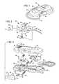
- FIG. 9is a perspective view of another infusion device embodying various aspects of the present invention.
- FIG. 10is a schematic representation of the valves and pump of the device of FIG. 9 between medicament dosage delivery and for filling the pump with the medicament;
- FIG. 11is a schematic representation of the valves and pump of the device of FIG. 9 during medicament dosage delivery;
- FIG. 12is an exploded perspective view of the device of FIG. 9 ;
- FIG. 13is a perspective view of one component of the device of FIG. 9 ;
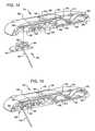
- FIG. 14is a lengthwise sectional view in perspective of the device of FIG. 9 and showing a cannula assembly for use therein in exploded view;
- FIG. 15is a lengthwise sectional view in perspective of the device of FIG. 9 similar to FIG. 14 showing the cannula assembly in operative association with the device;
- FIG. 16is a sectional plan view showing the valve configuration of the device of FIG. 9 during pump filling
- FIG. 17is a sectional plan view showing the valve configuration of the device of FIG. 9 during medicament delivery;
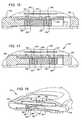
- FIG. 18is a sectional view, in perspective, to an enlarged scale, showing the actuation linkages of the device of FIG. 9 prior to medicament dosage delivery;
- FIG. 19is a sectional view like that of FIG. 18 , showing the actuation linkages of the device of FIG. 9 during medicament dosage delivery;
- FIG. 20is a sectional view like that of FIG. 18 , showing the actuation linkages of the device of FIG. 9 after medicament dosage delivery;
- FIG. 21is a another sectional view, in perspective, to an enlarged scale, showing the operation of the actuation linkages
- FIG. 22is another sectional view like that of FIG. 21 , in perspective, to an enlarged scale, showing the operation of the actuation linkages;
- FIG. 23is still another sectional view showing the last dose lock-out and the device pump during normal medicament delivery actuation
- FIG. 24is a sectional view, like that of FIG. 23 , showing the last dose lock-out and device pump after normal medicament delivery;
- FIG. 25is a sectional view, like that of FIG. 23 , showing the last dose lock-out being conditioned for disabling the actuator upon return of the device pump after a last normal medicament delivery;
- FIG. 26is a sectional view, like that of FIG. 23 , showing the last dose lock-out disabling the actuator upon a final medicament delivery;
- FIG. 27is another sectional view, to an enlarged scale, showing the device pump and the fill port being blocked during actuation for delivery of medicament;
- FIG. 28is another sectional view, like that of FIG. 22 , showing the device pump and the fill port being locked in a blocked condition by the last dose lock-out.
- FIG. 1it is a perspective view of a first infusion device embodying certain aspects of the present invention.
- the device 10generally includes an enclosure 12 , a base 14 , a first actuator control button 16 , and a second actuator control button 18 .
- the enclosure 12is formed by virtue of multiple device layers being brought together. Each layer defines various components of the device such as, for example, a reservoir, fluid conduits, pump chambers, and valve chambers, for example.
- This form of device constructionin accordance with aspects of the present invention, enables manufacturing economy to an extent rendering the device disposable after use.
- the base 14preferably includes an adhesive coating to permit the device to be adhered to a patient's skin.
- the adhesive coatingmay originally be covered with a releasable cover that may be pealed off of the base 14 when the patient endeavors to deploy the device 10 .
- Such arrangementsare well known in the art.
- the device 10may be mated with a previously deployed cannula assembly. However, it is contemplated herein that the various aspects of the present invention may be realized within a device that may be alternatively first adhered to the patient's skin followed by the deployment of a cannula thereafter.
- the actuator buttons 16 and 18are placed on opposites sides of the device 10 and directly across from each other. This renders more convenient the concurrent depression of the buttons when the patient wishes to receive a dose of the liquid medicament contained within the device 10 . This arrangement also imposes substantially equal and opposite forces on the device during dosage delivery to prevent the device from being displaced and possibly stripped from the patient. As will be further seen hereinafter, the concurrent depression of the buttons is used to particular advantage.
- the actuator button 16may serve as a valve control which, when in a first position as shown, establishes a first fluid path between the device reservoir and the device pump to support pump filling, and then, when in a second or depressed position, establishes a second fluid path between the device pump and the device outlet or cannula to permit dosage delivery to the patient.
- a linkage between the control actuator buttons 16 and 18permits actuation of the device pump with the actuator control button 18 only when the second fluid path has been established by the first actuator control button 16 .
- the first actuator control button 16may be considered a safety control.
- the device 10further includes a fill port 20 , a reservoir 22 , a pump 24 , and the cannula 30 .
- the devicefurther includes a first valve 32 and a second valve 34 .
- Fluid conduit 40provides a fluid connection between the fill port 20 and the reservoir 22
- fluid conduit 42provides a fluid connection between the reservoir 22 and the first valve 32
- fluid conduit 44provides a fluid connection between the first valve 32 and the pump 24
- fluid conduit 46provides a fluid connection between the pump 24 and the second valve 34
- fluid conduit 48provides a fluid connection between the second valve 34 and the device outlet 50 .
- the outlet 50is arranged to communicate with the cannula 30 .
- the actuator buttons 16 and 18are spring loaded by springs 36 and 38 .
- the springsare provided for returning the actuator buttons to the first position after a dosage is administered.
- the pump 24 of the device 10comprises a piston pump.
- the pump 24includes a pump piston 26 and a pump chamber 28 .
- the actuator control button 18is directly coupled to and is an extension of the pump piston 26 .
- the deviceadditionally includes a first linkage 52 and a second linkage 54 .
- the first linkageis a toggle linkage between the first valve 32 and the second valve 34 . It is arranged to assure that the second valve 34 does not open until after the first valve 32 is closed.
- the second linkage 54is between the first actuator button 16 and the second actuator button 18 . It is arranged to assure that the pump does not pump until after the first valve is closed and the second valve is opened by the first actuator button 16 .
- the second valve 34is a safety valve that closes tighter responsive to increased fluid pressure within fluid conduit 46 . This assures that the liquid medicament is not accidentally administered to the patient notwithstanding the inadvertent application of pressure to the reservoir, for example. In applications such as this, it is not uncommon for the reservoir to be formed of flexible material. While this has its advantages, it does present the risk that the reservoir may be accidentally squeezed as it is worn. Because the second valve only closes tighter under such conditions, it is assured that increased accidental reservoir pressure will not cause the fluid medicament to flow to the cannula.
- the reservoiris first filled through the fill port 20 to a desired level of medicament.
- the valves 32 and 34will be as shown.
- the first valve 32will be open and the second valve 34 will be closed. This permits the piston chamber 28 to be filled after the reservoir is filled.
- the cannula 30may then be deployed followed by the deployment of the device 10 .
- the valves 32 and 34will still be as shown.
- the first valve 32will be open and the second valve 34 will be closed. This permits the pump chamber 28 to be filled through a first fluid path including conduits 42 and 44 as the piston 24 returns to its first position after each applied dose.
- the actuator buttonsare concurrently pressed.
- the linkage 52causes the first valve 32 to close and the second valve 34 to thereafter open.
- the second linkage 54precludes actuation of the pump 24 until the first valve 32 is closed and the second valve 34 is opened by the first actuator button 16 .
- a second fluid pathis established from the pump 24 to the cannula 30 through fluid conduits 46 and 48 and the outlet 50 .
- the medicamentis then administered to the patient through cannula 30 .
- the piston 24and thus the actuator button 18 , is returned under the spring pressure of spring 38 to its initial position.
- a given volume of the liquid medicament for the next dosage deliveryis drawn from the reservoir into the pump chamber 28 to ready the device for its next dosage delivery.
- FIG. 3it is an exploded perspective view of the device of FIG. 1 . It shows the various component parts of the device.
- the main component partsinclude the aforementioned device layers including the base layer 60 , the reservoir membrane or intermediate layer 62 , and the top body layer 64 .
- the base layeris a substantially rigid unitary structure that defines a first reservoir portion 66 , the pump chamber 28 , and valve sockets 68 and 70 of the first and second valves respectively.
- the base layer 60may be formed of plastic, for example.
- the reservoir membrane layer 62is received over the reservoir portion 66 to form the reservoir 22 ( FIG. 2 ).
- a valve seat structure 72is received over the valve sockets 68 and 70 to form the first and second valves 32 and 34 ( FIG.2 ) respectively.
- a rocker 74is placed over the valves seat structure 72 to open and close the valves as will be seen subsequently.
- the pump actuator button 18carries the pump piston that is received within the pump chamber 28 .
- the pump actuator button 18also carries a cam cylinder 76 with a lock tube 78 therein that form a portion of the second linkage 54 ( FIG. 2 ).
- the spring 38returns the actuator button 18 to its first position after each dosage delivery.
- the first actuator control buttoncarries a valve timing cam 80 that rocks the rocker 72 .
- the button 16further carries a cam cylinder 82 and a cam pin 84 that is received into the cam cylinder 82 .
- the spring 36returns the actuator button 16 to its first position after each dosage delivery.
- the top body layer 64forms the top portion of the device enclosure. It receives a planar cap 86 that completes fluid paths 85 partially formed in the top layer 64 .
- a needle 88is provided that provides fluid coupling from the cannula (not shown) to the outlet of the device 10 .
- FIG. 4shows a sectional view, in perspective, of the device of FIG. 1 . More specifically, the figure shows details of the piston pump 24 within the device 10 .
- the piston 26 of the piston pump 24is received within the pump chamber 28 that is formed in the base layer 60 of the device.
- the piston 26may further be seen to be an extension of the actuator button 18 .
- An O-ring 90provides a seal between the pump chamber 28 and the piston 26 .
- the spring 38returns the actuator button 18 to its shown first position after each dosage delivery.
- FIG. 5is a sectional view, in perspective, of the device of FIG. 1 showing the valves 32 and 34 and the valve and actuation linkages prior to the delivery of a medicament dose.
- the valveswill first be described. First, it may be noted that the valve seat structure 72 is received within the valve sockets 68 and 70 .
- the valve seat structure 72includes valve seats 92 and 94 that are received within the valve sockets 68 and 70 respectively. Each of the seats 92 and 94 has a widened portion 96 and 98 , respectively, that cause the seats to be more tightly seated within sockets 68 and 70 in response to increased fluid pressure in the downward direction. As previously described, this protects against the potential effects of accidental medication delivery due to external pressure being applied to the reservoir of the device.
- the rocker 74opens and closes the valves 32 and 34 . It is under control of the timing cam 80 carried by the first actuator control button 16 . As the control button 16 is moved laterally, the cam 80 causes the rocker 74 to pivot and to apply pressure to one or the other of the valve seats 92 or 94 . The shape of the cam surfaces on the rocker 74 and the cam 80 assure that the valve 34 will not open until the valve 32 closes. The cam 80 and rocker 74 thus form the first linkage 52 shown in FIG. 2 .
- FIGS. 5-8show details of the second linkage.
- the second linkageincludes the cam cylinder 76 , the lock tube 78 , the outer cam cylinder 82 , and the cam pin 84 .
- the cam cylinderis integral with the second actuator control button 18 and the outer cam cylinder 82 is integral with the first actuator control button.
- the second linkage 54further includes a lock cylinder 100 . The foregoing are disposed in a bore 102 formed in the base layer 60 of the device.
- the end of the lock tube 78abuts the end of the lock cylinder 100 .
- the lock cylinderincludes ears 104 .
- the concurrent pushing of the buttons 16 and 18causes the outer cam cylinder 82 to slide over the lock cylinder 100 first and then the cam cylinder 76 to slide over the lock tube 78 .
- the sliding of the outer cam cylinder 82 over the lock cylinder 100causes the first valve to close and the second valve to open.
- the cam cylinder 76is then permitted to slide over lock tube 78 to cause the piston 26 to move through the pump chamber 28 . This displaces the liquid medicament in the pump chamber 28 for delivering the medicament to the cannula 30 and the patient.
- FIG. 7illustrates the manner in which the outer cam cylinder 82 slides along the lock cylinder 100 .
- the cam pin 84has a reduced diameter portion creating an annular space 106 between the pin 84 and the lock cylinder 100 .
- the outer cam cylinder 82engages the pin at a flange 108 of the pin 84 . This engagement will cause the pin 84 to move with the outer cam cylinder 82 .
- the pushing of the first actuator button 16will cause the outer cam cylinder 82 to engage the ears 104 of the lock cylinder 100 while at the same time, the end of the pin 84 moves into the lock tube 78 .
- the ears 104are depressed enough by the outer cam cylinder 82 as the end of the pin 84 clears the end of the depressed lock cylinder 100 to permit the ears 104 to enter space 106 . This occurs with a snap sound and feel as it occurs suddenly.
- the outer cam cylinder 82is now free to slide its complete travel distance over the lock cylinder 100 .
- the valve 32has now been closed and the valve 34 has been opened.
- the snap action of the actuator buttons 16 and 18provides positive assurance to the patient that a dosage of medicament was delivered. Also, because the snap action only occurs when the pump actuator button 18 completes it full travel, the patient will also know that a full dosage was delivered.
- the ears 104will be displaced sufficiently into space 106 to permit the cam cylinder 76 to clear the end of the lock cylinder 100 and slide over the lock tube 78 .
- the condition of the second linkage 54 at this timeis shown in FIG. 8 .
- the pump 24is actuated to deliver the medicament to the patient.
- the device 210generally includes an enclosure 212 , a base 214 , a first actuator control button 216 , and a second actuator control button 218 .
- the enclosure 212is formed by virtue of multiple device layers being brought together. Each layer defines various components of the device such as, for example, a reservoir, fluid conduits, pumps, and valve chambers, for example.
- This form of device constructionin accordance with aspects of the present invention, enables manufacturing economy to an extent rendering the device disposable after use.
- the base 214preferably includes an adhesive coating to permit the device to be adhered to a patient's skin.
- the adhesive coatingmay originally be covered with a releasable cover that may be pealed off of the base 214 when the patient endeavors to deploy the device 210 .
- Such arrangementsare well known in the art.
- the device 210may be mated with a previously deployed cannula assembly.
- the various aspects of the present inventionmay be realized within a device that may be alternatively first adhered to the patient's skin followed by the deployment of a cannula thereafter.
- the actuator buttons 216 and 218are placed on opposites sides of the device 210 and directly across from each other. This again renders more convenient the concurrent depression of the buttons when the patient wishes to receive a dose of the liquid medicament contained within the device 210 .
- This arrangementalso imposes substantially equal and opposite forces on the device during dosage delivery to prevent the device from being displaced and possibly stripped from the patient.
- the concurrent depression of the buttonsis used to particular advantage.
- the actuator button 216may serve as a valve control which, when in a first position as shown, establishes a first fluid path between the device reservoir and the device pump to support pump filling, and then, when in a second or depressed position, establishes a second fluid path between the device pump and the device outlet or cannula to permit dosage delivery to the patient.
- a linkage between the control actuator buttons 216 and 218permits actuation of the device pump with the actuator control button 218 only when the second fluid path has been established by the first actuator control button 216 .
- the first actuator control button 216may be considered a safety control.
- the device 210also includes a tactile indicator 260 that represents the volume of the liquid medicament delivered by the device with each actuation of the pump 224 .
- the tactile indicatoris carried by the pump actuator button 218 and takes the form of a plurality of distinct raised features or bumps 262 and 264 .
- the tactile indicatormay take the form of one or more distinct relieved portions.
- Each bump 262 and 264may correspond to a single unit of medicament. Hence, in this embodiment, the bumps 262 and 264 indicate that the device delivers two units of medicament with each actuation of the pump.
- the tactile indicator 260 being carried on the pump actuator control button 218provides a very significant feature and advantage.
- the pump actuator button 218has an integral extension that forms the piston 226 of the piston pump 224 as represented in FIG. 10 to be described hereinafter.
- the piston chamber 228is formed in a component of the device that may be used in devices delivering dosage amounts other than two units. The component may be common to all such devices because it would have a fixed piston chamber length and the dosage amount is determined by the throw of the pump piston 226 . Each piston throw is integral to the part and corresponds to a respective given dosage amount.
- Each pump actuator button for a given dosage amountmay have then be provided with a corresponding tactile indicator.
- a tactile indicatorindicates a dosage amount of two units, for example, it is assured that that is the medicament amount delivered with that particular pump button. Further, this arrangement is advantageous from a manufacturing standpoint because the actuator buttons for the various dosage size devices cannot be confused with each other.
- FIGS. 10 and 11are schematic representations of the valves and pump of the device of FIG. 9 between medicament dosage filling ( FIG. 10 ) and medicament dosage delivery ( FIG. 11 )
- the device 210further includes a reservoir 222 , a pump 224 , and the cannula 230 .
- the devicefurther includes a shuttle valve 231 forming a first valve 232 defined by O-rings 233 and 235 and a second valve 234 defined by O-rings 237 and 239 .
- O-ringsare used herein to form seals, other types of valve construction may best employ forms of seals other than O-rings without departing from the invention.
- Fluid conduit 240extends between the valves 232 and 234 .
- a fluid conduit 242provides a fluid connection between the reservoir 222 and the shuttle valve 231 and fluid conduit 244 provides a fluid connection between the shuttle valve 231 and the pump 224 .
- a further fluid conduit 246provides a fluid connection between the shuttle valve 231 and the device outlet 250 .
- the outlet 250in the form of a needle, is arranged to communicate with the cannula 230 .
- the actuator buttons 216 and 218are spring loaded by springs 236 and 238 .
- the springsare provided for returning the actuator buttons to the first position after a dosage is administered.
- the pump 224 of the device 210comprises a piston pump.
- the pump 224includes a pump piston 226 and a pump chamber 228 .
- the actuator control button 218is directly coupled to and is an extension of the pump piston 226 .
- the deviceadditionally includes a first linkage 252 and a second linkage 254 .
- the first linkageis formed by the shuttle bar 241 of the first valve 232 and the second valve 234 . It is arranged by separating the valves 232 and 234 be a distance that assures that the second valve 234 does not open until after the first valve 232 is closed.
- the second linkage 254is between the first actuator button 216 and the second actuator button 218 . It is arranged to assure that the pump 224 does not pump until after the first valve 232 is closed and the second valve 234 is opened by the first actuator button 216 .
- the second valve 234is a safety valve that assures that the liquid medicament is not accidentally administered to the patient notwithstanding the inadvertent application of pressure to the reservoir, for example.
- the reservoirIn applications such as this, it is not uncommon for the reservoir to be formed of flexible material. While this has its advantages, it does present the risk that the reservoir may be accidentally squeezed as it is worn. Because of the second valve 234 , it is assured that accidental reservoir pressure will not cause the fluid medicament to flow to the cannula.
- the pump chamber 228is first filled as the actuator button 218 returns to the first position after having just delivered a medicament dosage.
- the shuttle valve 231is set so that the first valve 232 will be open (the reservoir 222 communicates with the fluid conduit 240 ) and the second valve 234 will be closed (the conduit 246 is closed off from fluid conduit 240 ).
- Thisestablishes a first fluid path from the reservoir 222 to the pump 224 through conduits 242 , 240 and 244 that permits the piston chamber 228 to be filled by the reservoir as the actuator button is returned to its first position under the influence of the spring 238 .
- the actuator buttonsare concurrently pressed.
- the linkage 252causes the first valve 232 to close and the second valve 234 to thereafter open.
- the second linkage 254precludes actuation of the pump 224 until the first valve 332 is closed and the second valve 334 is opened by the first actuator button 216 .
- a second fluid pathis established from the pump 224 to the cannula 30 through fluid conduits 244 , 240 and 246 and the outlet 250 .
- the medicamentis then administered to the patient through cannula 30 .
- the piston 224and thus the actuator button 218 , is returned under the spring pressure of spring 238 to its initial position.
- a given volume of the liquid medicament for the next dosage deliveryis drawn from the reservoir into the pump chamber 228 as described above to ready the device for its next dosage delivery.
- FIG. 12it is an exploded perspective view of the device of FIG. 9 . It shows the various component parts of the device 210 .
- the device 210is constructed in device layers including a base layer 280 , an intermediate layer 282 , and the top body layer 284 .
- the base layer 280is a substantially rigid unitary structure that defines a first reservoir portion 286 , the pump chamber 228 , and a valve chamber 290 for the first and second valves 232 and 234 .
- the base layer 280may be formed of plastic, for example.
- the valve chamber 290is arranged to receive the valve shuttle bar 241 carried by and extending from the first actuator button 216 .
- O-rings 233 , 235 , 237 , and 239are arranged to be seated on the shuttle bar 241 to form the first and second valves 232 and 234 respectively ( FIG. 10 ).
- the actuator button 216also carries a first portion 292 of the second linkage 254 ( FIG. 10 ).
- the second linkageis received within a suitably configured bore 295 formed in the base layer 280 and will be described subsequently.
- the pump actuator button 218carries the pump piston 226 and a second portion 294 of the second linkage 254 .
- the pump piston 226is arranged to be received within the pump chamber 228 and the second portion 294 of the second linkage 254 is arranged to be received within the bore 295 for interacting with the first portion 292 .
- O-rings 300 and 302are arranged to be seated on the piston 226 to provide a seal against leakage and to prevent external contaminants from entering the piston chamber.
- the base layer 280further includes fluid channels 304 that serve to form the fluid conduits illustrated in FIG. 10 .
- springs 306 and 308are arranged to spring load the actuator buttons 216 and 218 .
- the intermediate layer 282is formed of flexible membrane material. A portion 296 of the intermediate layer is received over the reservoir portion 286 to form the reservoir 222 ( FIG. 10 ). A rigid plate 310 is arranged to be adhered to the portion 296 of the reservoir. Because the layer 282 is flexible membrane, it will move as the reservoir is filled and emptied. The rigid plate 310 will then move with it.
- the plateincludes an eyelet 312 dimensioned to receive an elongated web 314 that forms a part of a medicament level indicator to be described hereinafter.
- the web 314carries an indicator line or feature 316 .
- the top layer 284is arranged to be received over the intermediate layer 282 and adhered to the base layer. It includes a panel 320 having a view window 318 through which the medicament level indicator line may be observed.
- the device 210further includes a pin 322 .
- the pin 322is a locking pin that is employed to lock the actuator buttons after a last medicament dose is delivered. It also serves to maintain the device fill port, to be described subsequently, in a blocked condition after a last medicament dose is delivered.
- FIGS. 14 and 15are lengthwise sectional views, in perspective, of the device of FIG. 9 along with a cannula assembly that may be deployed in the device.
- FIG. 14illustrates the previously described layered structure of the device 210 including device layers 280 , 282 , and 284 .
- the deviceincludes a port for receiving a cannula assembly 340 .
- the cannula assemblyhas a base 342 , a generally cylindrical docking structure 344 , and a cannula 346 .
- the docking structure 344is arranged to be received by the port 330 ( FIG.
- the deviceincludes a needle 348 that projects through a septum 350 of the device when the cannula assembly 340 is received by the port 330 . This completes the fluid path from the reservoir 222 to the cannula 346 .
- FIGS. 14 and 15also clearly illustrate a medicament level indicator embodying the present invention.
- the rigid plate 310forms a moveable wall that moves as the medicament volume increases and decreases within the reservoir.
- the elongated web 316is preferably formed from a non-elastic, non-compressible, elongated material. It has a first end 352 and a second end 354 .
- the webis fixed at the first end 352 with respect to the rigid plate 310 of the reservoir 222 and is arranged to move in a first plane generally perpendicular to the rigid plate 310 intermediate the first and second ends 352 and 354 . Because the web 316 is fixed at the first end 352 and free to move within the eyelet 312 , its second end 354 will move in linear movement in a second plane substantially parallel to the rigid member and transverse to the first plane.
- a panel 320 of the top layer 284has a window opening 318 to render the medicament level indicia viewable.
- the cover panel 320forms a guide channel 356 that receives and confines the web second end to guide the web for linear movement in the second plane substantially transverse to the first plane. As the reservoir is filled or emptied, a glance through the window 318 will provide an indication of the level of the medicament in the reservoir 222 .
- FIG. 16it is a sectional plan view showing the valve configuration of the device 210 of FIG. 9 during medicament filling of the pump chamber 228 immediately after a dosage delivery.
- the first actuator button 216has an extension comprising the shuttle bar 241 of the valves 232 and 234 .
- the conduits from the reservoir, from the pump, and to the cannulaMore particularly, the conduit 242 is in fluid communication with the reservoir 222 ( FIG. 10 ), the conduit 244 is in fluid communication with the pump, and the conduit 246 is in fluid communication with the cannula.
- valvesare shown with the first valve 232 opened and not blocking the reservoir conduit 242 , and the second valve 234 closed and blocking the conduit 246 to the cannula. This permits medicament to flow from the reservoir through conduit 242 and to the pump chamber 228 through conduit 244 as the actuator button 216 returns to its first position. Hence, the pump chamber is filled and ready for the next dosage delivery.
- FIG. 17it is a sectional plan view showing the valve configuration of the device 210 of FIG. 9 during medicament delivery.
- the valvesare shown with the first valve 232 closed and blocking the reservoir conduit 242 , and the second valve 234 open permitting medicament to flow from the pump through conduit 244 and to the cannula through conduit 246 .
- the first and second valves 232 and 234are spaced apart so that conduit 242 is blocked before conduit 246 is opened.
- FIGS. 18-22show details of the operation of the second linkage 254 of the device 210 .
- the first actuator button 216has an extension 380 that terminates in a block 382 having a first ramp surface 384 and a second ramp surface 386 .
- the button 216is concurrently depressed with pump button 218 . It and its extension 380 and bloc 382 are free to move to the right.
- the pump actuator button 218has parallel extensions 400 and 402 which are joined and separated be a rod member 404 . As seen in FIG.
- the extension 400abuts an abutment 388 which it must clear to be able to move to the left.
- the button 216As shown in FIG. 21 , as the button 216 is depressed, its extension 380 moves to the right causing the first ramp surface to engage the rod member 404 . Continued movement of the button causes the rod member 404 to rise up under the first ramp surface 384 which in turn causes the extension 400 to begin to move slightly to the left and bend upward about rib 405 . Eventually, the rod member 404 rides up the length of the first ramp 384 causing the end 401 of extension 400 to clear the abutment 388 as shown in FIG. 19 . The pump button 216 is now able to move freely to the left.
- the pump button 218could not at first move freely while the first actuator button 216 which operates the valves could.
- the pump actuationlags behind the valve actuation causing the first valve 232 ( FIG. 10 ) to be closed and the second valve 234 to be opened, establishing a medicament delivery flow path to the cannula, before the pump is able to begin pumping the medicament to the patient. Because this operation occurs quickly, it appears to the patient that both actuator buttons are moving at the same rate.
- the spring loading of the actuator buttonsreturns the buttons to their first or initial position.
- the same timing provided by the block 382is used for recharging the pump. More specifically, ramp 366 unlatches the end 401 of extension 400 by lifting rod member 404 so that 246 is closed and conduit 242 is opened before the pump is returned by the spring to its initial position. This assures that the pump does not pull medicament from the patient but only from the reservoir. As the piston 226 of the piston pump 224 returns, a full dose of the medicament is drawn up into the piston chamber 228 to ready the device for the next dosage delivery.
- FIGS. 23 and 24show the operation of the piston pump 224 in greater detail. Also shown is a last dose lock-out 420 that will be described subsequently.
- the piston 226 of pump 224is an extension of the pump actuator button 218 .
- the O-rings 300 and 302seal the piston 226 and the chamber 228 . The double O-rings both prevent leakage of medicament from the camber 228 and prevent outside contaminants from entering the chamber 228 .
- medicamentflows from the reservoir, through a conduit 307 ( FIG. 13 ), through a diaphragm chamber 424 and through the conduit 244 to the pump chamber 228 .
- the chamber 424is defined by a diaphragm 422 formed of flexible membrane material.
- the diaphragm 422includes an extension which captures the pin 322 , previously shown in the exploded view of FIG. 12 . As long as the reservoir has medicament, and hence is not empty, the diaphragm 422 is not affected. In this state, the button 216 is free to be actuated.
- the pinis L-shaped at end 323 with an L-extension 428 .
- a capture ramp 430integral with the actuator button, passes adjacent to the pin 322 and over the L-extension 328 . This occurs when the actuator button is depressed as long as the reservoir has sufficient medicament to provide at least one more dosage delivery.
- FIGS. 25 and 26As the reservoir has insufficient medicament to support delivery of another dose of medicament, and during the return of the actuator button 218 after what will be the last dose delivered, a negative pressure is created in the diaphragm chamber 424 . This causes the diaphragm 422 to be drawn into the chamber 424 due to the absence of liquid medicament in the chamber 424 . As the diaphragm 422 is drawn into the chamber 424 , the pin 322 is drawn upward with the diaphragm 422 where it engages an abutment 432 connected to the ramp extension 430 . The pin 322 is now caused to be captured between the ramp 430 and the abutment 432 .
- the button 216is now only partially returned to its first position whereas the pump actuator button 218 is free to fully return to its initial position.
- the L-extensionwill ride up the ramp 430 and fall into a locked position between the ramp 430 and a shoulder 434 formed in the actuator button 216 .
- the buttonis now locked and cannot be returned to its first position.
- the pump actuator button 218will also be locked in its second position as shown in FIG. 26 . This is due to the fact that the first button 216 is not able to return from its second position which, as shown in FIG. 20 , causes the end 401 of the extension 400 of the pump actuator 218 be locked between the abutment 388 and actuator button 216 .
- the device 210is now locked and cannot be reused.
- FIGS. 27 and 28they illustrate a further aspect of the last dose lock-out.
- the device 210Before the device 210 can be used to deliver a medicament, its reservoir must be filled with a medicament. To this end, the device 210 is provided with a fill port 440 that communicates with the reservoir. When the device 210 is filled with medicament, the actuator buttons 216 and 218 are in their initial positions. The first actuator button 216 further includes another extension 442 which does not cover the fill port 440 when the actuator button 216 is in its initial position. However, when the actuator button 216 is in its fully actuated second position, it does block the fill port 440 as seen in FIG. 28 .
- the actuator button 216When the last dose lock-out has the locked the device, the actuator button 216 is left in its fully actuated second position. As a result, the last dose lock-out not only locks both actuator buttons 216 and 218 to disable the device 210 , it also blocks the fill port 440 to further render the device disabled.
Landscapes
- Health & Medical Sciences (AREA)
- Vascular Medicine (AREA)
- Engineering & Computer Science (AREA)
- Anesthesiology (AREA)
- Biomedical Technology (AREA)
- Heart & Thoracic Surgery (AREA)
- Hematology (AREA)
- Life Sciences & Earth Sciences (AREA)
- Animal Behavior & Ethology (AREA)
- General Health & Medical Sciences (AREA)
- Public Health (AREA)
- Veterinary Medicine (AREA)
- Dermatology (AREA)
- Infusion, Injection, And Reservoir Apparatuses (AREA)
- External Artificial Organs (AREA)
Abstract
Description
Claims (16)
Priority Applications (9)
| Application Number | Priority Date | Filing Date | Title |
|---|---|---|---|
| US11/906,126US8128596B2 (en) | 2007-09-28 | 2007-09-28 | Disposable infusion device layered structure |
| US11/906,130US8226607B2 (en) | 2007-09-28 | 2007-09-28 | Disposable infusion device with dual valve system |
| CA2739183ACA2739183C (en) | 2007-09-28 | 2008-09-23 | Disposable infusion device with dual valve system |
| JP2010527070AJP5461408B2 (en) | 2007-09-28 | 2008-09-23 | Disposable infusion device with double valve system |
| PCT/US2008/077332WO2009045784A2 (en) | 2007-09-28 | 2008-09-23 | Disposable infusion device layered structure |
| PCT/US2008/077314WO2009045776A2 (en) | 2007-09-28 | 2008-09-23 | Disposable infusion device with dual valve system |
| EP08835828.8AEP2197517B8 (en) | 2007-09-28 | 2008-09-23 | Disposable infusion device with dual valve system |
| CN2008801094935ACN101808681B (en) | 2007-09-28 | 2008-09-23 | Disposable infusion device with dual valve system |
| IL204733AIL204733A (en) | 2007-09-28 | 2010-03-25 | Disposable infusion device with dual valve system |
Applications Claiming Priority (2)
| Application Number | Priority Date | Filing Date | Title |
|---|---|---|---|
| US11/906,126US8128596B2 (en) | 2007-09-28 | 2007-09-28 | Disposable infusion device layered structure |
| US11/906,130US8226607B2 (en) | 2007-09-28 | 2007-09-28 | Disposable infusion device with dual valve system |
Publications (2)
| Publication Number | Publication Date |
|---|---|
| US20090088693A1 US20090088693A1 (en) | 2009-04-02 |
| US8128596B2true US8128596B2 (en) | 2012-03-06 |
Family
ID=40601195
Family Applications (2)
| Application Number | Title | Priority Date | Filing Date |
|---|---|---|---|
| US11/906,130Active2029-12-11US8226607B2 (en) | 2007-09-28 | 2007-09-28 | Disposable infusion device with dual valve system |
| US11/906,126Active2029-07-12US8128596B2 (en) | 2007-09-28 | 2007-09-28 | Disposable infusion device layered structure |
Family Applications Before (1)
| Application Number | Title | Priority Date | Filing Date |
|---|---|---|---|
| US11/906,130Active2029-12-11US8226607B2 (en) | 2007-09-28 | 2007-09-28 | Disposable infusion device with dual valve system |
Country Status (7)
| Country | Link |
|---|---|
| US (2) | US8226607B2 (en) |
| EP (1) | EP2197517B8 (en) |
| JP (1) | JP5461408B2 (en) |
| CN (1) | CN101808681B (en) |
| CA (1) | CA2739183C (en) |
| IL (1) | IL204733A (en) |
| WO (2) | WO2009045776A2 (en) |
Cited By (38)
| Publication number | Priority date | Publication date | Assignee | Title |
|---|---|---|---|---|
| USD692552S1 (en) | 2011-11-08 | 2013-10-29 | Becton Dickinson France, S.A.S. | Microinfuser |
| USD692997S1 (en) | 2011-11-08 | 2013-11-05 | Becton Dickinson France, S.A.S. | Microinfuser |
| USD693455S1 (en) | 2011-11-08 | 2013-11-12 | Becton, Dickinson And Company | Microinfuser |
| US20140231461A1 (en)* | 2013-02-20 | 2014-08-21 | Albea Lacrost | Unit For Dispensing A Product Comprising A Case And A Cassette |
| US9373269B2 (en) | 2013-03-18 | 2016-06-21 | Lifescan Scotland Limited | Patch pump training device |
| USD767120S1 (en) | 2015-07-30 | 2016-09-20 | Becton, Dickinson And Company | Medical injector |
| USD774640S1 (en) | 2015-07-30 | 2016-12-20 | Becton, Dickinson And Company | Medical injector |
| USD776265S1 (en) | 2015-07-30 | 2017-01-10 | Becton, Dickinson And Company | Medical injector |
| USD776263S1 (en) | 2015-07-30 | 2017-01-10 | Becton, Dickinson And Company | Medical injector |
| USD776264S1 (en) | 2015-07-30 | 2017-01-10 | Becton, Dickinson And Company | Medical injector |
| USD776262S1 (en) | 2015-07-30 | 2017-01-10 | Becton, Dickinson And Company | Medical injector |
| USD794776S1 (en) | 2015-07-30 | 2017-08-15 | Becton, Dickinson And Company | Medical injector |
| USD805631S1 (en) | 2016-01-21 | 2017-12-19 | Becton, Dickinson And Company | Drug delivery device with insertion mechanism button safety |
| USD806232S1 (en) | 2016-01-21 | 2017-12-26 | Becton, Dickinson And Company | Drug delivery device with insertion mechanism |
| USD829889S1 (en) | 2016-01-21 | 2018-10-02 | Becton, Dickinson And Company | Wearable drug delivery device with adhesive |
| USD829894S1 (en) | 2016-01-21 | 2018-10-02 | Becton, Dickinson And Company | Wearable drug delivery device baseplate |
| USD830537S1 (en) | 2016-01-21 | 2018-10-09 | Becton, Dickinson And Company | Wearable drug delivery device with adhesive and liner |
| US10096223B1 (en) | 2013-12-18 | 2018-10-09 | Cerner Innovication, Inc. | Method and process for determining whether an individual suffers a fall requiring assistance |
| USD830547S1 (en) | 2016-01-21 | 2018-10-09 | Becton, Dickinson And Company | Adhesive liner for wearable drug delivery device |
| US10217342B2 (en) | 2011-07-12 | 2019-02-26 | Cerner Innovation, Inc. | Method and process for determining whether an individual suffers a fall requiring assistance |
| US10303924B2 (en) | 2015-12-31 | 2019-05-28 | Cerner Innovation, Inc. | Methods and systems for detecting prohibited objects in a patient room |
| US10342478B2 (en) | 2015-05-07 | 2019-07-09 | Cerner Innovation, Inc. | Method and system for determining whether a caretaker takes appropriate measures to prevent patient bedsores |
| US10382724B2 (en) | 2014-01-17 | 2019-08-13 | Cerner Innovation, Inc. | Method and system for determining whether an individual takes appropriate measures to prevent the spread of healthcare-associated infections along with centralized monitoring |
| USD857191S1 (en) | 2016-01-21 | 2019-08-20 | Becton, Dickinson And Company | Wearable drug delivery device |
| US10482321B2 (en) | 2017-12-29 | 2019-11-19 | Cerner Innovation, Inc. | Methods and systems for identifying the crossing of a virtual barrier |
| US10510443B2 (en) | 2014-12-23 | 2019-12-17 | Cerner Innovation, Inc. | Methods and systems for determining whether a monitored individual's hand(s) have entered a virtual safety zone |
| US10524722B2 (en) | 2014-12-26 | 2020-01-07 | Cerner Innovation, Inc. | Method and system for determining whether a caregiver takes appropriate measures to prevent patient bedsores |
| US10546481B2 (en) | 2011-07-12 | 2020-01-28 | Cerner Innovation, Inc. | Method for determining whether an individual leaves a prescribed virtual perimeter |
| US10602095B1 (en) | 2014-01-17 | 2020-03-24 | Cerner Innovation, Inc. | Method and system for determining whether an individual takes appropriate measures to prevent the spread of healthcare-associated infections |
| US10643446B2 (en) | 2017-12-28 | 2020-05-05 | Cerner Innovation, Inc. | Utilizing artificial intelligence to detect objects or patient safety events in a patient room |
| US10874794B2 (en) | 2011-06-20 | 2020-12-29 | Cerner Innovation, Inc. | Managing medication administration in clinical care room |
| US10922936B2 (en) | 2018-11-06 | 2021-02-16 | Cerner Innovation, Inc. | Methods and systems for detecting prohibited objects |
| US11007317B2 (en) | 2018-05-02 | 2021-05-18 | Cequr Sa | Devices and methods for providing a bolus dose in a microfluidic circuit of a pump |
| WO2024042222A1 (en) | 2022-08-26 | 2024-02-29 | Cequr Sa | Add-on device for medicament dose tracking |
| US12005237B2 (en) | 2016-01-21 | 2024-06-11 | West Pharma. Services IL, Ltd. | Medicament delivery device comprising a visual indicator |
| US12148512B2 (en) | 2019-12-31 | 2024-11-19 | Cerner Innovation, Inc. | Patient safety using virtual observation |
| US12208246B2 (en) | 2015-10-09 | 2025-01-28 | West Pharma. Services IL, Ltd. | Bent fluid path add on to a prefilled fluid reservoir |
| US12420011B2 (en) | 2018-02-16 | 2025-09-23 | Cequr Sa | Devices and methods for flow restriction in a microfluidic circuit for drug delivery |
Families Citing this family (88)
| Publication number | Priority date | Publication date | Assignee | Title |
|---|---|---|---|---|
| US8247946B2 (en) | 2004-06-14 | 2012-08-21 | Massachusetts Institute Of Technology | Electrochemical actuator |
| WO2005124918A2 (en) | 2004-06-14 | 2005-12-29 | Massachusetts Institute Of Technology | Electrochemical actuating methods, devices and structures |
| US7994686B2 (en)* | 2004-06-14 | 2011-08-09 | Massachusetts Institute Of Technology | Electrochemical methods, devices, and structures |
| US7999435B2 (en)* | 2004-06-14 | 2011-08-16 | Massachusetts Institute Of Technology | Electrochemical actuator |
| US7872396B2 (en) | 2004-06-14 | 2011-01-18 | Massachusetts Institute Of Technology | Electrochemical actuator |
| US7981380B2 (en)* | 2006-02-10 | 2011-07-19 | Solazzi Monte J | Sample cup with thin-film detachment mechanism |
| EP2178584A2 (en)* | 2007-07-26 | 2010-04-28 | Entra Pharmaceuticals Inc. | Skin-patch pump comprising a changing-volume electrochemical actuator |
| US9345836B2 (en) | 2007-10-02 | 2016-05-24 | Medimop Medical Projects Ltd. | Disengagement resistant telescoping assembly and unidirectional method of assembly for such |
| BRPI0817907B8 (en) | 2007-10-02 | 2021-06-22 | Lamodel Ltd | apparatus for administering a substance to an individual |
| US7967795B1 (en) | 2010-01-19 | 2011-06-28 | Lamodel Ltd. | Cartridge interface assembly with driving plunger |
| US9656019B2 (en) | 2007-10-02 | 2017-05-23 | Medimop Medical Projects Ltd. | Apparatuses for securing components of a drug delivery system during transport and methods of using same |
| US10420880B2 (en) | 2007-10-02 | 2019-09-24 | West Pharma. Services IL, Ltd. | Key for securing components of a drug delivery system during assembly and/or transport and methods of using same |
| US8540673B2 (en)* | 2008-03-18 | 2013-09-24 | Calibra Medical, Inc. | Disposable infusion device with actuation lock-out |
| USD611853S1 (en) | 2008-03-21 | 2010-03-16 | Lifescan Scotland Limited | Analyte test meter |
| USD612275S1 (en) | 2008-03-21 | 2010-03-23 | Lifescan Scotland, Ltd. | Analyte test meter |
| USD615431S1 (en) | 2008-03-21 | 2010-05-11 | Lifescan Scotland Limited | Analyte test meter |
| US7976500B2 (en) | 2008-06-26 | 2011-07-12 | Calibra Medical, Inc. | Disposable infusion device with redundant valved safety |
| US8128597B2 (en)* | 2008-06-26 | 2012-03-06 | Calibra Medical, Inc. | Disposable infusion device with cannula port cover |
| USD611489S1 (en) | 2008-07-25 | 2010-03-09 | Lifescan, Inc. | User interface display for a glucose meter |
| US8109912B2 (en)* | 2008-09-12 | 2012-02-07 | Calibra Medical, Inc. | Wearable infusion assembly |
| US12097357B2 (en) | 2008-09-15 | 2024-09-24 | West Pharma. Services IL, Ltd. | Stabilized pen injector |
| US9393369B2 (en) | 2008-09-15 | 2016-07-19 | Medimop Medical Projects Ltd. | Stabilized pen injector |
| USD611372S1 (en)* | 2008-09-19 | 2010-03-09 | Lifescan Scotland Limited | Analyte test meter |
| US8613719B2 (en) | 2008-11-03 | 2013-12-24 | Calibra Medical, Inc. | Dosage sensing unit with tactile feedback |
| US20100217233A1 (en)* | 2009-02-20 | 2010-08-26 | Ranft Elizabeth A | Method and device to anesthetize an area |
| IN2012DN01517A (en)* | 2009-07-23 | 2015-06-05 | Swissinnov Product S Rl | |
| US10071196B2 (en) | 2012-05-15 | 2018-09-11 | West Pharma. Services IL, Ltd. | Method for selectively powering a battery-operated drug-delivery device and device therefor |
| US8157769B2 (en) | 2009-09-15 | 2012-04-17 | Medimop Medical Projects Ltd. | Cartridge insertion assembly for drug delivery system |
| US10071198B2 (en) | 2012-11-02 | 2018-09-11 | West Pharma. Servicees IL, Ltd. | Adhesive structure for medical device |
| US8449504B2 (en) | 2009-11-11 | 2013-05-28 | Calibra Medical, Inc. | Wearable infusion device and system |
| US8348898B2 (en) | 2010-01-19 | 2013-01-08 | Medimop Medical Projects Ltd. | Automatic needle for drug pump |
| USD652503S1 (en)* | 2010-04-08 | 2012-01-17 | Cequr Sa | Medical device |
| WO2011140359A2 (en) | 2010-05-05 | 2011-11-10 | Springleaf Therapeutics, Inc. | Systems and methods for delivering a therapeutic agent |
| EP2569031B1 (en) | 2010-05-10 | 2017-10-11 | Medimop Medical Projects Ltd. | Low volume accurate injector |
| US9216249B2 (en) | 2010-09-24 | 2015-12-22 | Perqflo, Llc | Infusion pumps |
| US9381300B2 (en) | 2010-09-24 | 2016-07-05 | Perqflo, Llc | Infusion pumps |
| US8915879B2 (en) | 2010-09-24 | 2014-12-23 | Perqflo, Llc | Infusion pumps |
| US9498573B2 (en) | 2010-09-24 | 2016-11-22 | Perqflo, Llc | Infusion pumps |
| US8905972B2 (en) | 2010-11-20 | 2014-12-09 | Perqflo, Llc | Infusion pumps |
| WO2012083174A2 (en) | 2010-12-17 | 2012-06-21 | Massachusetts Institute Of Technology | Electrochemical actuators |
| USD702834S1 (en) | 2011-03-22 | 2014-04-15 | Medimop Medical Projects Ltd. | Cartridge for use in injection device |
| EP2809375B1 (en) | 2012-01-31 | 2021-08-11 | Medimop Medical Projects Ltd. | Time dependent drug delivery apparatus |
| CN204910157U (en) | 2012-03-05 | 2015-12-30 | 贝克顿·迪金森公司 | System for be used for at body liquid conveying |
| US9072827B2 (en) | 2012-03-26 | 2015-07-07 | Medimop Medical Projects Ltd. | Fail safe point protector for needle safety flap |
| US10668213B2 (en) | 2012-03-26 | 2020-06-02 | West Pharma. Services IL, Ltd. | Motion activated mechanisms for a drug delivery device |
| US9463280B2 (en) | 2012-03-26 | 2016-10-11 | Medimop Medical Projects Ltd. | Motion activated septum puncturing drug delivery device |
| US9527075B2 (en) | 2012-11-05 | 2016-12-27 | Austen Bioinnovation Institute In Akron | Low-volume syringe pipette |
| US9421323B2 (en) | 2013-01-03 | 2016-08-23 | Medimop Medical Projects Ltd. | Door and doorstop for portable one use drug delivery apparatus |
| US20140296784A1 (en)* | 2013-03-27 | 2014-10-02 | Animas Corporation | Infusion device with layered structure having durable and disposable components |
| US9011164B2 (en) | 2013-04-30 | 2015-04-21 | Medimop Medical Projects Ltd. | Clip contact for easy installation of printed circuit board PCB |
| US9889256B2 (en) | 2013-05-03 | 2018-02-13 | Medimop Medical Projects Ltd. | Sensing a status of an infuser based on sensing motor control and power input |
| US10076750B2 (en) | 2014-02-04 | 2018-09-18 | Austen Bioinnovation Institute In Akron | Plunger for low-volume syringe pipette |
| US11464899B2 (en) | 2014-08-28 | 2022-10-11 | Becton, Dickinson And Company | Wireless communication for on-body medical devices |
| WO2016040423A1 (en) | 2014-09-10 | 2016-03-17 | Becton, Dickinson And Company | Activation system and method for on-body medical devices |
| US10159786B2 (en) | 2014-09-30 | 2018-12-25 | Perqflo, Llc | Hybrid ambulatory infusion pumps |
| US12178992B2 (en) | 2014-09-30 | 2024-12-31 | Medtronic Minimed, Inc. | Different disposable assemblies for the same reusable assembly |
| US10737016B2 (en) | 2015-02-18 | 2020-08-11 | Medtronic Minimed, Inc. | Ambulatory infusion pumps and reservoir assemblies for use with same |
| US9795534B2 (en) | 2015-03-04 | 2017-10-24 | Medimop Medical Projects Ltd. | Compliant coupling assembly for cartridge coupling of a drug delivery device |
| US10251813B2 (en) | 2015-03-04 | 2019-04-09 | West Pharma. Services IL, Ltd. | Flexibly mounted cartridge alignment collar for drug delivery device |
| US10293120B2 (en) | 2015-04-10 | 2019-05-21 | West Pharma. Services IL, Ltd. | Redundant injection device status indication |
| US9744297B2 (en) | 2015-04-10 | 2017-08-29 | Medimop Medical Projects Ltd. | Needle cannula position as an input to operational control of an injection device |
| CN107735121B (en)* | 2015-05-08 | 2019-02-15 | 以色列三级跳远有限责任公司 | Systems and devices for infusion of fluids into the body |
| US10149943B2 (en) | 2015-05-29 | 2018-12-11 | West Pharma. Services IL, Ltd. | Linear rotation stabilizer for a telescoping syringe stopper driverdriving assembly |
| CN113181477B (en) | 2015-06-04 | 2023-07-14 | 麦迪麦珀医疗工程有限公司 | Cartridge insertion for drug delivery device |
| US10086145B2 (en) | 2015-09-22 | 2018-10-02 | West Pharma Services Il, Ltd. | Rotation resistant friction adapter for plunger driver of drug delivery device |
| US9987432B2 (en) | 2015-09-22 | 2018-06-05 | West Pharma. Services IL, Ltd. | Rotation resistant friction adapter for plunger driver of drug delivery device |
| US11318254B2 (en) | 2015-10-09 | 2022-05-03 | West Pharma. Services IL, Ltd. | Injector needle cap remover |
| BR112018008903A8 (en)* | 2015-11-02 | 2019-02-26 | Lifecell Corp | devices and methods for automated filling and distribution of shear-controlled adipose tissue |
| USD801346S1 (en)* | 2015-12-04 | 2017-10-31 | Hand Held Products, Inc. | Wearable module |
| US10646643B2 (en) | 2016-01-21 | 2020-05-12 | West Pharma. Services IL, Ltd. | Needle insertion and retraction mechanism |
| EP3711793B1 (en) | 2016-01-21 | 2021-12-01 | West Pharma Services IL, Ltd. | A method of connecting a cartridge to an automatic injector |
| EP3413954B1 (en) | 2016-02-12 | 2025-09-03 | Medtronic MiniMed, Inc. | Ambulatory infusion pump and assemblies for use with same |
| US11389597B2 (en) | 2016-03-16 | 2022-07-19 | West Pharma. Services IL, Ltd. | Staged telescopic screw assembly having different visual indicators |
| US10376647B2 (en) | 2016-03-18 | 2019-08-13 | West Pharma. Services IL, Ltd. | Anti-rotation mechanism for telescopic screw assembly |
| CN109310831B (en) | 2016-06-02 | 2021-11-23 | 西医药服务以色列有限公司 | Three position needle retraction |
| US11338090B2 (en) | 2016-08-01 | 2022-05-24 | West Pharma. Services IL, Ltd. | Anti-rotation cartridge pin |
| JP7059251B2 (en) | 2016-08-01 | 2022-04-25 | ウェスト ファーマ サービシーズ イスラエル リミテッド | A spring that prevents the door from closing halfway |
| CN109843369B (en)* | 2016-10-17 | 2021-11-09 | 拜耳医药保健有限公司 | Fluid control valve and manifold |
| EP3630226A1 (en) | 2017-05-30 | 2020-04-08 | West Pharma. Services Il, Ltd. | Modular drive train for wearable injector |
| CN119868710A (en) | 2017-06-15 | 2025-04-25 | 以色列三级跳远有限责任公司 | Patch pump system and device for managing diabetes and method thereof |
| US12214156B2 (en) | 2017-08-28 | 2025-02-04 | Triple Jump Israel Ltd. | Systems, methods, apparatuses and devices for drug or substance delivery |
| JP7402799B2 (en) | 2017-12-22 | 2023-12-21 | ウェスト ファーマ サービシーズ イスラエル リミテッド | Syringes available with different cartridge sizes |
| JP7066003B2 (en) | 2018-04-09 | 2022-05-12 | エフ ホフマン-ラ ロッシュ アクチェン ゲゼルシャフト | Methods and devices for delivering insulin |
| US12048793B2 (en) | 2018-06-11 | 2024-07-30 | Epicentrx, Inc. | Medication infusion devices, systems, and methods |
| US11174852B2 (en) | 2018-07-20 | 2021-11-16 | Becton, Dickinson And Company | Reciprocating pump |
| WO2021119433A1 (en) | 2019-12-11 | 2021-06-17 | Epicentrx, Inc. | Medication infusion devices, systems, and methods |
| CN112023191B (en)* | 2020-09-14 | 2021-03-12 | 广州大麦生物科技有限公司 | Biological electronic equipment |
| US11419976B1 (en) | 2021-04-30 | 2022-08-23 | Fresenius Kabi Deutschland Gmbh | Wearable drug delivery device with pressurized fluid dispensing |
Citations (9)
| Publication number | Priority date | Publication date | Assignee | Title |
|---|---|---|---|---|
| US1619652A (en) | 1925-03-14 | 1927-03-01 | Carter Benjamin Charles | Centrifugal separator |
| US5830187A (en)* | 1995-12-22 | 1998-11-03 | Science Incorporated | Fluid delivery device with conformable ullage and fill assembly |
| US5957895A (en) | 1998-02-20 | 1999-09-28 | Becton Dickinson And Company | Low-profile automatic injection device with self-emptying reservoir |
| US6186982B1 (en) | 1998-05-05 | 2001-02-13 | Elan Corporation, Plc | Subcutaneous drug delivery device with improved filling system |
| US6749587B2 (en) | 2001-02-22 | 2004-06-15 | Insulet Corporation | Modular infusion device and method |
| US20060196552A1 (en)* | 2005-02-17 | 2006-09-07 | Kriesel Marshall S | Distal rate control device |
| US7128727B2 (en)* | 2002-09-30 | 2006-10-31 | Flaherty J Christopher | Components and methods for patient infusion device |
| US20080097327A1 (en)* | 2006-08-23 | 2008-04-24 | Medtronic Minimed, Inc. | Systems and methods allowing for reservoir filling and infusion medium delivery |
| US20080188810A1 (en)* | 2005-02-25 | 2008-08-07 | Novo Nordisk A/S | Pump Assembly With Safety Valve |
Family Cites Families (15)
| Publication number | Priority date | Publication date | Assignee | Title |
|---|---|---|---|---|
| US4619652A (en)* | 1982-12-23 | 1986-10-28 | Alza Corporation | Dosage form for use in a body mounted pump |
| US4596248A (en)* | 1984-11-23 | 1986-06-24 | Lieberman Edgar M | Tracheostomy device |
| US6645175B2 (en)* | 1996-12-18 | 2003-11-11 | Science Incorporated | Variable rate infusion apparatus with indicator and adjustable rate control |
| US6500150B1 (en)* | 1997-06-16 | 2002-12-31 | Elan Pharma International Limited | Pre-filled drug-delivery device and method of manufacture and assembly of same |
| US6702779B2 (en)* | 2000-08-18 | 2004-03-09 | Becton, Dickinson And Company | Constant rate fluid delivery device with selectable flow rate and titratable bolus button |
| US6669669B2 (en)* | 2001-10-12 | 2003-12-30 | Insulet Corporation | Laminated patient infusion device |
| US6723072B2 (en)* | 2002-06-06 | 2004-04-20 | Insulet Corporation | Plunger assembly for patient infusion device |
| WO2004056412A2 (en)* | 2002-12-23 | 2004-07-08 | M2 Medical A/S | A disposable, wearable insulin dispensing device, a combination of such a device and a programming controller and a method of controlling the operation of such a device |
| US6923791B2 (en)* | 2003-03-31 | 2005-08-02 | Sterling Medivations, Inc. | Infusion device having offset flow path |
| EP1475113A1 (en)* | 2003-05-08 | 2004-11-10 | Novo Nordisk A/S | External needle inserter |
| WO2005037350A2 (en)* | 2003-10-21 | 2005-04-28 | Novo Nordisk A/S | Internal fluid connector for establishing a fluid connection |
| KR20060099520A (en)* | 2003-10-21 | 2006-09-19 | 노보 노르디스크 에이/에스 | Medical Skin Mounting Device |
| US7309326B2 (en)* | 2003-11-18 | 2007-12-18 | Icu Medical, Inc. | Infusion set |
| WO2006108775A2 (en) | 2005-04-08 | 2006-10-19 | Novo Nordisk A/S | Pump assembly with active and passive valve |
| US7637279B2 (en)* | 2006-01-20 | 2009-12-29 | Smiths Medical Asd, Inc. | Shuttle valve |
- 2007
- 2007-09-28USUS11/906,130patent/US8226607B2/enactiveActive
- 2007-09-28USUS11/906,126patent/US8128596B2/enactiveActive
- 2008
- 2008-09-23CACA2739183Apatent/CA2739183C/enactiveActive
- 2008-09-23JPJP2010527070Apatent/JP5461408B2/enactiveActive
- 2008-09-23CNCN2008801094935Apatent/CN101808681B/enactiveActive
- 2008-09-23EPEP08835828.8Apatent/EP2197517B8/enactiveActive
- 2008-09-23WOPCT/US2008/077314patent/WO2009045776A2/enactiveApplication Filing
- 2008-09-23WOPCT/US2008/077332patent/WO2009045784A2/enactiveApplication Filing
- 2010
- 2010-03-25ILIL204733Apatent/IL204733A/enactiveIP Right Grant
Patent Citations (9)
| Publication number | Priority date | Publication date | Assignee | Title |
|---|---|---|---|---|
| US1619652A (en) | 1925-03-14 | 1927-03-01 | Carter Benjamin Charles | Centrifugal separator |
| US5830187A (en)* | 1995-12-22 | 1998-11-03 | Science Incorporated | Fluid delivery device with conformable ullage and fill assembly |
| US5957895A (en) | 1998-02-20 | 1999-09-28 | Becton Dickinson And Company | Low-profile automatic injection device with self-emptying reservoir |
| US6186982B1 (en) | 1998-05-05 | 2001-02-13 | Elan Corporation, Plc | Subcutaneous drug delivery device with improved filling system |
| US6749587B2 (en) | 2001-02-22 | 2004-06-15 | Insulet Corporation | Modular infusion device and method |
| US7128727B2 (en)* | 2002-09-30 | 2006-10-31 | Flaherty J Christopher | Components and methods for patient infusion device |
| US20060196552A1 (en)* | 2005-02-17 | 2006-09-07 | Kriesel Marshall S | Distal rate control device |
| US20080188810A1 (en)* | 2005-02-25 | 2008-08-07 | Novo Nordisk A/S | Pump Assembly With Safety Valve |
| US20080097327A1 (en)* | 2006-08-23 | 2008-04-24 | Medtronic Minimed, Inc. | Systems and methods allowing for reservoir filling and infusion medium delivery |
Non-Patent Citations (1)
| Title |
|---|
| International Search Report for International Application No. PCT?US2008/077332 dated Jun. 8, 2009 conducted by Korean Intellectual Property Office. |
Cited By (64)
| Publication number | Priority date | Publication date | Assignee | Title |
|---|---|---|---|---|
| US10874794B2 (en) | 2011-06-20 | 2020-12-29 | Cerner Innovation, Inc. | Managing medication administration in clinical care room |
| US10217342B2 (en) | 2011-07-12 | 2019-02-26 | Cerner Innovation, Inc. | Method and process for determining whether an individual suffers a fall requiring assistance |
| US10546481B2 (en) | 2011-07-12 | 2020-01-28 | Cerner Innovation, Inc. | Method for determining whether an individual leaves a prescribed virtual perimeter |
| USD692552S1 (en) | 2011-11-08 | 2013-10-29 | Becton Dickinson France, S.A.S. | Microinfuser |
| USD692997S1 (en) | 2011-11-08 | 2013-11-05 | Becton Dickinson France, S.A.S. | Microinfuser |
| USD693455S1 (en) | 2011-11-08 | 2013-11-12 | Becton, Dickinson And Company | Microinfuser |
| USD711527S1 (en) | 2011-11-08 | 2014-08-19 | Becton, Dickinson And Company | Microinfuser |
| US20140231461A1 (en)* | 2013-02-20 | 2014-08-21 | Albea Lacrost | Unit For Dispensing A Product Comprising A Case And A Cassette |
| US9139341B2 (en)* | 2013-02-20 | 2015-09-22 | Albea Lacrost | Unit for dispensing a product comprising a case and a cassette |
| US9373269B2 (en) | 2013-03-18 | 2016-06-21 | Lifescan Scotland Limited | Patch pump training device |
| US10229571B2 (en) | 2013-12-18 | 2019-03-12 | Cerner Innovation, Inc. | Systems and methods for determining whether an individual suffers a fall requiring assistance |
| US10096223B1 (en) | 2013-12-18 | 2018-10-09 | Cerner Innovication, Inc. | Method and process for determining whether an individual suffers a fall requiring assistance |
| US10602095B1 (en) | 2014-01-17 | 2020-03-24 | Cerner Innovation, Inc. | Method and system for determining whether an individual takes appropriate measures to prevent the spread of healthcare-associated infections |
| US10382724B2 (en) | 2014-01-17 | 2019-08-13 | Cerner Innovation, Inc. | Method and system for determining whether an individual takes appropriate measures to prevent the spread of healthcare-associated infections along with centralized monitoring |
| US10491862B2 (en) | 2014-01-17 | 2019-11-26 | Cerner Innovation, Inc. | Method and system for determining whether an individual takes appropriate measures to prevent the spread of healthcare-associated infections along with centralized monitoring |
| US10510443B2 (en) | 2014-12-23 | 2019-12-17 | Cerner Innovation, Inc. | Methods and systems for determining whether a monitored individual's hand(s) have entered a virtual safety zone |
| US10524722B2 (en) | 2014-12-26 | 2020-01-07 | Cerner Innovation, Inc. | Method and system for determining whether a caregiver takes appropriate measures to prevent patient bedsores |
| US10342478B2 (en) | 2015-05-07 | 2019-07-09 | Cerner Innovation, Inc. | Method and system for determining whether a caretaker takes appropriate measures to prevent patient bedsores |
| US11317853B2 (en) | 2015-05-07 | 2022-05-03 | Cerner Innovation, Inc. | Method and system for determining whether a caretaker takes appropriate measures to prevent patient bedsores |
| USD776263S1 (en) | 2015-07-30 | 2017-01-10 | Becton, Dickinson And Company | Medical injector |
| USD776265S1 (en) | 2015-07-30 | 2017-01-10 | Becton, Dickinson And Company | Medical injector |
| USD794776S1 (en) | 2015-07-30 | 2017-08-15 | Becton, Dickinson And Company | Medical injector |
| USD774640S1 (en) | 2015-07-30 | 2016-12-20 | Becton, Dickinson And Company | Medical injector |
| USD767120S1 (en) | 2015-07-30 | 2016-09-20 | Becton, Dickinson And Company | Medical injector |
| USD776264S1 (en) | 2015-07-30 | 2017-01-10 | Becton, Dickinson And Company | Medical injector |
| USD776262S1 (en) | 2015-07-30 | 2017-01-10 | Becton, Dickinson And Company | Medical injector |
| US12208246B2 (en) | 2015-10-09 | 2025-01-28 | West Pharma. Services IL, Ltd. | Bent fluid path add on to a prefilled fluid reservoir |
| US11363966B2 (en) | 2015-12-31 | 2022-06-21 | Cerner Innovation, Inc. | Detecting unauthorized visitors |
| US11241169B2 (en) | 2015-12-31 | 2022-02-08 | Cerner Innovation, Inc. | Methods and systems for detecting stroke symptoms |
| US11937915B2 (en) | 2015-12-31 | 2024-03-26 | Cerner Innovation, Inc. | Methods and systems for detecting stroke symptoms |
| US11666246B2 (en) | 2015-12-31 | 2023-06-06 | Cerner Innovation, Inc. | Methods and systems for assigning locations to devices |
| US10303924B2 (en) | 2015-12-31 | 2019-05-28 | Cerner Innovation, Inc. | Methods and systems for detecting prohibited objects in a patient room |
| US10410042B2 (en) | 2015-12-31 | 2019-09-10 | Cerner Innovation, Inc. | Detecting unauthorized visitors |
| US10878220B2 (en) | 2015-12-31 | 2020-12-29 | Cerner Innovation, Inc. | Methods and systems for assigning locations to devices |
| US10643061B2 (en) | 2015-12-31 | 2020-05-05 | Cerner Innovation, Inc. | Detecting unauthorized visitors |
| US10614288B2 (en) | 2015-12-31 | 2020-04-07 | Cerner Innovation, Inc. | Methods and systems for detecting stroke symptoms |
| USD829889S1 (en) | 2016-01-21 | 2018-10-02 | Becton, Dickinson And Company | Wearable drug delivery device with adhesive |
| USD878553S1 (en) | 2016-01-21 | 2020-03-17 | Becton, Dickinson And Company | Wearable drug delivery device |
| USD805631S1 (en) | 2016-01-21 | 2017-12-19 | Becton, Dickinson And Company | Drug delivery device with insertion mechanism button safety |
| USD878552S1 (en) | 2016-01-21 | 2020-03-17 | Becton, Dickinson And Company | Wearable drug delivery device |
| USD830547S1 (en) | 2016-01-21 | 2018-10-09 | Becton, Dickinson And Company | Adhesive liner for wearable drug delivery device |
| USD829894S1 (en) | 2016-01-21 | 2018-10-02 | Becton, Dickinson And Company | Wearable drug delivery device baseplate |
| US12005237B2 (en) | 2016-01-21 | 2024-06-11 | West Pharma. Services IL, Ltd. | Medicament delivery device comprising a visual indicator |
| USD830537S1 (en) | 2016-01-21 | 2018-10-09 | Becton, Dickinson And Company | Wearable drug delivery device with adhesive and liner |
| USD857191S1 (en) | 2016-01-21 | 2019-08-20 | Becton, Dickinson And Company | Wearable drug delivery device |
| US12427261B2 (en) | 2016-01-21 | 2025-09-30 | West Pharma. Services IL, Ltd. | Medicament delivery device comprising a visual indicator |
| USD836193S1 (en) | 2016-01-21 | 2018-12-18 | Becton, Dickinson And Company | Adhesive liner for wearable drug delivery device |
| USD806232S1 (en) | 2016-01-21 | 2017-12-26 | Becton, Dickinson And Company | Drug delivery device with insertion mechanism |
| US10922946B2 (en) | 2017-12-28 | 2021-02-16 | Cerner Innovation, Inc. | Utilizing artificial intelligence to detect objects or patient safety events in a patient room |
| US11276291B2 (en) | 2017-12-28 | 2022-03-15 | Cerner Innovation, Inc. | Utilizing artificial intelligence to detect objects or patient safety events in a patient room |
| US11721190B2 (en) | 2017-12-28 | 2023-08-08 | Cerner Innovation, Inc. | Utilizing artificial intelligence to detect objects or patient safety events in a patient room |
| US12008880B2 (en) | 2017-12-28 | 2024-06-11 | Cerner Innovation, Inc. | Utilizing artificial intelligence to detect objects or patient safety events in a patient room |
| US12394296B2 (en) | 2017-12-28 | 2025-08-19 | Cerner Innovation, Inc. | Utilizing artificial intelligence to detect objects or patient safety events in a patient room |
| US10643446B2 (en) | 2017-12-28 | 2020-05-05 | Cerner Innovation, Inc. | Utilizing artificial intelligence to detect objects or patient safety events in a patient room |
| US11074440B2 (en) | 2017-12-29 | 2021-07-27 | Cerner Innovation, Inc. | Methods and systems for identifying the crossing of a virtual barrier |
| US11544953B2 (en) | 2017-12-29 | 2023-01-03 | Cerner Innovation, Inc. | Methods and systems for identifying the crossing of a virtual barrier |
| US10482321B2 (en) | 2017-12-29 | 2019-11-19 | Cerner Innovation, Inc. | Methods and systems for identifying the crossing of a virtual barrier |
| US12420011B2 (en) | 2018-02-16 | 2025-09-23 | Cequr Sa | Devices and methods for flow restriction in a microfluidic circuit for drug delivery |
| US11007317B2 (en) | 2018-05-02 | 2021-05-18 | Cequr Sa | Devices and methods for providing a bolus dose in a microfluidic circuit of a pump |
| US12257417B2 (en) | 2018-05-02 | 2025-03-25 | Cequr Sa | Devices and methods for providing a bolus dose in a microfluidic circuit of a pump |
| US10922936B2 (en) | 2018-11-06 | 2021-02-16 | Cerner Innovation, Inc. | Methods and systems for detecting prohibited objects |
| US11443602B2 (en) | 2018-11-06 | 2022-09-13 | Cerner Innovation, Inc. | Methods and systems for detecting prohibited objects |
| US12148512B2 (en) | 2019-12-31 | 2024-11-19 | Cerner Innovation, Inc. | Patient safety using virtual observation |
| WO2024042222A1 (en) | 2022-08-26 | 2024-02-29 | Cequr Sa | Add-on device for medicament dose tracking |
Also Published As
| Publication number | Publication date |
|---|---|
| IL204733A0 (en) | 2010-11-30 |
| EP2197517B1 (en) | 2019-04-17 |
| CN101808681B (en) | 2012-10-10 |
| WO2009045784A2 (en) | 2009-04-09 |
| CA2739183C (en) | 2015-12-29 |
| EP2197517A2 (en) | 2010-06-23 |
| IL204733A (en) | 2013-03-24 |
| EP2197517B8 (en) | 2019-06-19 |
| EP2197517A4 (en) | 2013-01-09 |
| US20090088693A1 (en) | 2009-04-02 |
| CA2739183A1 (en) | 2009-04-09 |
| JP2010540093A (en) | 2010-12-24 |
| US8226607B2 (en) | 2012-07-24 |
| WO2009045776A3 (en) | 2009-06-04 |
| WO2009045776A2 (en) | 2009-04-09 |
| WO2009045784A3 (en) | 2009-08-06 |
| CN101808681A (en) | 2010-08-18 |
| JP5461408B2 (en) | 2014-04-02 |
| US20090088694A1 (en) | 2009-04-02 |
Similar Documents
| Publication | Publication Date | Title |
|---|---|---|
| US8128596B2 (en) | Disposable infusion device layered structure | |
| US8226606B2 (en) | Disposable infusion device with tactile dosage volume indicator | |
| US7771391B2 (en) | Disposable infusion device with snap action actuation | |
| EP2767299A1 (en) | Disposable infusion device with dual valve system | |
| US7976493B2 (en) | Disposable infusion device with resettable last dose lock-out | |
| AU2019201034A1 (en) | Infusion device with layered structure having durable and disposable components | |
| CA2739185C (en) | Disposable infusion device with reuse lock-out | |
| HK1151254B (en) | Disposable infusion device with reuse lock-out | |
| HK1201224B (en) | Disposable infusion device with dual valve system |
Legal Events
| Date | Code | Title | Description |
|---|---|---|---|
| AS | Assignment | Owner name:SEATTLE MEDICAL TECHNOLOGIES, INC., CALIFORNIA Free format text:ASSIGNMENT OF ASSIGNORS INTEREST;ASSIGNOR:CARTER, BRETT J.;REEL/FRAME:020331/0553 Effective date:20071107 | |
| AS | Assignment | Owner name:CALIBRA MEDICAL, INC., CALIFORNIA Free format text:CHANGE OF NAME;ASSIGNOR:SEATTLE MEDICAL TECHNOLOGIES, INC.;REEL/FRAME:021204/0708 Effective date:20080616 Owner name:CALIBRA MEDICAL, INC.,CALIFORNIA Free format text:CHANGE OF NAME;ASSIGNOR:SEATTLE MEDICAL TECHNOLOGIES, INC.;REEL/FRAME:021204/0708 Effective date:20080616 | |
| AS | Assignment | Owner name:JOHNSON & JOHNSON DEVELOPMENT CORPORATION, NEW JER Free format text:SECURITY AGREEMENT;ASSIGNOR:CALIBRA MEDICAL, INC.;REEL/FRAME:027449/0936 Effective date:20111222 | |
| STCF | Information on status: patent grant | Free format text:PATENTED CASE | |
| FEPP | Fee payment procedure | Free format text:PAT HOLDER NO LONGER CLAIMS SMALL ENTITY STATUS, ENTITY STATUS SET TO UNDISCOUNTED (ORIGINAL EVENT CODE: STOL); ENTITY STATUS OF PATENT OWNER: LARGE ENTITY | |
| FPAY | Fee payment | Year of fee payment:4 | |
| MAFP | Maintenance fee payment | Free format text:PAYMENT OF MAINTENANCE FEE, 8TH YEAR, LARGE ENTITY (ORIGINAL EVENT CODE: M1552); ENTITY STATUS OF PATENT OWNER: LARGE ENTITY Year of fee payment:8 | |
| MAFP | Maintenance fee payment | Free format text:PAYMENT OF MAINTENANCE FEE, 12TH YEAR, LARGE ENTITY (ORIGINAL EVENT CODE: M1553); ENTITY STATUS OF PATENT OWNER: LARGE ENTITY Year of fee payment:12 |