US8128572B2 - Signal processing apparatus - Google Patents
Signal processing apparatusDownload PDFInfo
- Publication number
- US8128572B2 US8128572B2US12/277,221US27722108AUS8128572B2US 8128572 B2US8128572 B2US 8128572B2US 27722108 AUS27722108 AUS 27722108AUS 8128572 B2US8128572 B2US 8128572B2
- Authority
- US
- United States
- Prior art keywords
- signal
- signals
- primary
- pulse rate
- light source
- Prior art date
- Legal status (The legal status is an assumption and is not a legal conclusion. Google has not performed a legal analysis and makes no representation as to the accuracy of the status listed.)
- Expired - Fee Related, expires
Links
Images


Classifications
- A—HUMAN NECESSITIES
- A61—MEDICAL OR VETERINARY SCIENCE; HYGIENE
- A61B—DIAGNOSIS; SURGERY; IDENTIFICATION
- A61B5/00—Measuring for diagnostic purposes; Identification of persons
- A61B5/02—Detecting, measuring or recording for evaluating the cardiovascular system, e.g. pulse, heart rate, blood pressure or blood flow
- A61B5/0205—Simultaneously evaluating both cardiovascular conditions and different types of body conditions, e.g. heart and respiratory condition
- A—HUMAN NECESSITIES
- A61—MEDICAL OR VETERINARY SCIENCE; HYGIENE
- A61B—DIAGNOSIS; SURGERY; IDENTIFICATION
- A61B5/00—Measuring for diagnostic purposes; Identification of persons
- A61B5/145—Measuring characteristics of blood in vivo, e.g. gas concentration or pH-value ; Measuring characteristics of body fluids or tissues, e.g. interstitial fluid or cerebral tissue
- A61B5/14546—Measuring characteristics of blood in vivo, e.g. gas concentration or pH-value ; Measuring characteristics of body fluids or tissues, e.g. interstitial fluid or cerebral tissue for measuring analytes not otherwise provided for, e.g. ions, cytochromes
- A—HUMAN NECESSITIES
- A61—MEDICAL OR VETERINARY SCIENCE; HYGIENE
- A61B—DIAGNOSIS; SURGERY; IDENTIFICATION
- A61B5/00—Measuring for diagnostic purposes; Identification of persons
- A61B5/145—Measuring characteristics of blood in vivo, e.g. gas concentration or pH-value ; Measuring characteristics of body fluids or tissues, e.g. interstitial fluid or cerebral tissue
- A61B5/1455—Measuring characteristics of blood in vivo, e.g. gas concentration or pH-value ; Measuring characteristics of body fluids or tissues, e.g. interstitial fluid or cerebral tissue using optical sensors, e.g. spectral photometrical oximeters
- A61B5/14551—Measuring characteristics of blood in vivo, e.g. gas concentration or pH-value ; Measuring characteristics of body fluids or tissues, e.g. interstitial fluid or cerebral tissue using optical sensors, e.g. spectral photometrical oximeters for measuring blood gases
- A61B5/14552—Details of sensors specially adapted therefor
- A—HUMAN NECESSITIES
- A61—MEDICAL OR VETERINARY SCIENCE; HYGIENE
- A61B—DIAGNOSIS; SURGERY; IDENTIFICATION
- A61B5/00—Measuring for diagnostic purposes; Identification of persons
- A61B5/48—Other medical applications
- A61B5/4821—Determining level or depth of anaesthesia
- A—HUMAN NECESSITIES
- A61—MEDICAL OR VETERINARY SCIENCE; HYGIENE
- A61B—DIAGNOSIS; SURGERY; IDENTIFICATION
- A61B5/00—Measuring for diagnostic purposes; Identification of persons
- A61B5/72—Signal processing specially adapted for physiological signals or for diagnostic purposes
- A61B5/7203—Signal processing specially adapted for physiological signals or for diagnostic purposes for noise prevention, reduction or removal
- A61B5/7207—Signal processing specially adapted for physiological signals or for diagnostic purposes for noise prevention, reduction or removal of noise induced by motion artifacts
- A61B5/7214—Signal processing specially adapted for physiological signals or for diagnostic purposes for noise prevention, reduction or removal of noise induced by motion artifacts using signal cancellation, e.g. based on input of two identical physiological sensors spaced apart, or based on two signals derived from the same sensor, for different optical wavelengths
- A—HUMAN NECESSITIES
- A61—MEDICAL OR VETERINARY SCIENCE; HYGIENE
- A61B—DIAGNOSIS; SURGERY; IDENTIFICATION
- A61B5/00—Measuring for diagnostic purposes; Identification of persons
- A61B5/72—Signal processing specially adapted for physiological signals or for diagnostic purposes
- A61B5/7235—Details of waveform analysis
- A61B5/7246—Details of waveform analysis using correlation, e.g. template matching or determination of similarity
- A—HUMAN NECESSITIES
- A61—MEDICAL OR VETERINARY SCIENCE; HYGIENE
- A61B—DIAGNOSIS; SURGERY; IDENTIFICATION
- A61B5/00—Measuring for diagnostic purposes; Identification of persons
- A61B5/72—Signal processing specially adapted for physiological signals or for diagnostic purposes
- A61B5/7235—Details of waveform analysis
- A61B5/7253—Details of waveform analysis characterised by using transforms
- A61B5/7257—Details of waveform analysis characterised by using transforms using Fourier transforms
- A—HUMAN NECESSITIES
- A61—MEDICAL OR VETERINARY SCIENCE; HYGIENE
- A61B—DIAGNOSIS; SURGERY; IDENTIFICATION
- A61B5/00—Measuring for diagnostic purposes; Identification of persons
- A61B5/72—Signal processing specially adapted for physiological signals or for diagnostic purposes
- A61B5/7235—Details of waveform analysis
- A61B5/7253—Details of waveform analysis characterised by using transforms
- A61B5/726—Details of waveform analysis characterised by using transforms using Wavelet transforms
- A—HUMAN NECESSITIES
- A61—MEDICAL OR VETERINARY SCIENCE; HYGIENE
- A61B—DIAGNOSIS; SURGERY; IDENTIFICATION
- A61B8/00—Diagnosis using ultrasonic, sonic or infrasonic waves
- A61B8/52—Devices using data or image processing specially adapted for diagnosis using ultrasonic, sonic or infrasonic waves
- A61B8/5269—Devices using data or image processing specially adapted for diagnosis using ultrasonic, sonic or infrasonic waves involving detection or reduction of artifacts
- A61B8/5276—Devices using data or image processing specially adapted for diagnosis using ultrasonic, sonic or infrasonic waves involving detection or reduction of artifacts due to motion
- H—ELECTRICITY
- H04—ELECTRIC COMMUNICATION TECHNIQUE
- H04B—TRANSMISSION
- H04B1/00—Details of transmission systems, not covered by a single one of groups H04B3/00 - H04B13/00; Details of transmission systems not characterised by the medium used for transmission
- H04B1/06—Receivers
- H04B1/10—Means associated with receiver for limiting or suppressing noise or interference
- H04B1/12—Neutralising, balancing, or compensation arrangements
- H04B1/123—Neutralising, balancing, or compensation arrangements using adaptive balancing or compensation means
- A—HUMAN NECESSITIES
- A61—MEDICAL OR VETERINARY SCIENCE; HYGIENE
- A61B—DIAGNOSIS; SURGERY; IDENTIFICATION
- A61B5/00—Measuring for diagnostic purposes; Identification of persons
- A61B5/02—Detecting, measuring or recording for evaluating the cardiovascular system, e.g. pulse, heart rate, blood pressure or blood flow
- A61B5/021—Measuring pressure in heart or blood vessels
- A61B5/0215—Measuring pressure in heart or blood vessels by means inserted into the body
- A61B5/02154—Measuring pressure in heart or blood vessels by means inserted into the body by optical transmission
- A—HUMAN NECESSITIES
- A61—MEDICAL OR VETERINARY SCIENCE; HYGIENE
- A61B—DIAGNOSIS; SURGERY; IDENTIFICATION
- A61B5/00—Measuring for diagnostic purposes; Identification of persons
- A61B5/02—Detecting, measuring or recording for evaluating the cardiovascular system, e.g. pulse, heart rate, blood pressure or blood flow
- A61B5/024—Measuring pulse rate or heart rate
- A—HUMAN NECESSITIES
- A61—MEDICAL OR VETERINARY SCIENCE; HYGIENE
- A61B—DIAGNOSIS; SURGERY; IDENTIFICATION
- A61B5/00—Measuring for diagnostic purposes; Identification of persons
- A61B5/02—Detecting, measuring or recording for evaluating the cardiovascular system, e.g. pulse, heart rate, blood pressure or blood flow
- A61B5/026—Measuring blood flow
- A61B5/029—Measuring blood output from the heart, e.g. minute volume
- A—HUMAN NECESSITIES
- A61—MEDICAL OR VETERINARY SCIENCE; HYGIENE
- A61B—DIAGNOSIS; SURGERY; IDENTIFICATION
- A61B5/00—Measuring for diagnostic purposes; Identification of persons
- A61B5/08—Measuring devices for evaluating the respiratory organs
- A61B5/0816—Measuring devices for examining respiratory frequency
- A—HUMAN NECESSITIES
- A61—MEDICAL OR VETERINARY SCIENCE; HYGIENE
- A61B—DIAGNOSIS; SURGERY; IDENTIFICATION
- A61B5/00—Measuring for diagnostic purposes; Identification of persons
- A61B5/145—Measuring characteristics of blood in vivo, e.g. gas concentration or pH-value ; Measuring characteristics of body fluids or tissues, e.g. interstitial fluid or cerebral tissue
- A61B5/14532—Measuring characteristics of blood in vivo, e.g. gas concentration or pH-value ; Measuring characteristics of body fluids or tissues, e.g. interstitial fluid or cerebral tissue for measuring glucose, e.g. by tissue impedance measurement
- A—HUMAN NECESSITIES
- A61—MEDICAL OR VETERINARY SCIENCE; HYGIENE
- A61B—DIAGNOSIS; SURGERY; IDENTIFICATION
- A61B5/00—Measuring for diagnostic purposes; Identification of persons
- A61B5/24—Detecting, measuring or recording bioelectric or biomagnetic signals of the body or parts thereof
- A61B5/316—Modalities, i.e. specific diagnostic methods
- A61B5/318—Heart-related electrical modalities, e.g. electrocardiography [ECG]
- A—HUMAN NECESSITIES
- A61—MEDICAL OR VETERINARY SCIENCE; HYGIENE
- A61B—DIAGNOSIS; SURGERY; IDENTIFICATION
- A61B5/00—Measuring for diagnostic purposes; Identification of persons
- A61B5/24—Detecting, measuring or recording bioelectric or biomagnetic signals of the body or parts thereof
- A61B5/316—Modalities, i.e. specific diagnostic methods
- A61B5/369—Electroencephalography [EEG]
- A—HUMAN NECESSITIES
- A61—MEDICAL OR VETERINARY SCIENCE; HYGIENE
- A61B—DIAGNOSIS; SURGERY; IDENTIFICATION
- A61B6/00—Apparatus or devices for radiation diagnosis; Apparatus or devices for radiation diagnosis combined with radiation therapy equipment
- A—HUMAN NECESSITIES
- A61—MEDICAL OR VETERINARY SCIENCE; HYGIENE
- A61B—DIAGNOSIS; SURGERY; IDENTIFICATION
- A61B8/00—Diagnosis using ultrasonic, sonic or infrasonic waves
- G—PHYSICS
- G06—COMPUTING OR CALCULATING; COUNTING
- G06F—ELECTRIC DIGITAL DATA PROCESSING
- G06F2218/00—Aspects of pattern recognition specially adapted for signal processing
- G06F2218/02—Preprocessing
- G06F2218/04—Denoising
Definitions
- the present inventionrelates to the field of signal processing. More specifically, the present invention relates to the processing of measured signals, containing a primary signal portion and a secondary signal portion, for the removal or derivation of either the primary or secondary signal portion when little is known about either of these components. More particularly, the present invention relates to modeling the measured signals in a novel way which facilitates minimizing the correlation between the primary signal portion and the secondary signal portion in order to produce a primary and/or secondary signal. The present invention is especially useful for physiological monitoring systems including blood oxygen saturation systems.
- Signal processorsare typically employed to remove or derive either the primary or secondary signal portion from a composite measured signal including a primary signal portion and a secondary signal portion.
- a composite signalmay contain noise and desirable portions. If the secondary signal portion occupies a different frequency spectrum than the primary signal portion, then conventional filtering techniques such as low pass, band pass, and high pass filtering are available to remove or derive either the primary or the secondary signal portion from the total signal. Fixed single or multiple notch filters could also be employed if the primary and/or secondary signal portion(s) exist at a fixed frequency(s).
- correlation cancelerssuch as adaptive noise cancelers, dynamically change their transfer function to adapt to and remove portions of a composite signal.
- correlation cancelersrequire either a secondary reference or a primary reference which correlates to either the secondary signal portion only or the primary signal portion only. For instance, for a measured signal containing noise and desirable signal, the noise can be removed with a correlation canceler if a noise reference is available. This is often the case.
- the amplitude of the reference signalsare not necessarily the same as the amplitude of the corresponding primary or secondary signal portions, they have a frequency spectrum which is similar to that of the primary or secondary signal portions.
- Physiological monitoringgenerally involves measured signals derived from a physiological system, such as the human body. Measurements which are typically taken with physiological monitoring systems include electrocardiographs, blood pressure, blood gas saturation (such as oxygen saturation), capnographs, other blood constituent monitoring, heart rate, respiration rate, electro-encephalograph (EEG) and depth of anesthesia, for example.
- EEGelectro-encephalograph
- measurementsinclude those which measure the pressure and quantity of a substance within the body such as cardiac output, venous oxygen saturation, arterial oxygen saturation, bilirubin, total hemoglobin, breathalyzer testing, drug testing, cholesterol testing, glucose testing, extra vasation, and carbon dioxide testing, protein testing, carbon monoxide testing, and other in-vivo measurements, for example. Complications arising in these measurements are often due to motion of the patient, both external and internal (muscle movement, vessel movement, and probe movement, for example), during the measurement process.
- a blood gas monitoris one example of a physiological monitoring system which is based upon the measurement of energy attenuated by biological tissues or substances.
- Blood gas monitorstransmit light into the test medium and measure the attenuation of the light as a function of time.
- the output signal of a blood gas monitor which is sensitive to the arterial blood flowcontains a component which is a waveform representative of the patient's arterial pulse.
- This type of signal, which contains a component related to the patient's pulseis called a plethysmographic wave, and is shown in FIG. 1 as curve s.
- Plethysmographic waveformsare used in blood gas saturation measurements.
- the amount of blood in the arteriesincreases and decreases, causing increases and decreases in energy attenuation, illustrated by the cyclic wave s in FIG. 1 .
- a digitsuch as a finger, an ear lobe, or other portion of the body where blood flows close to the skin
- the fingercomprises skin, fat, bone, muscle, etc., shown schematically in FIG. 2 , each of which attenuates energy incident on the finger in a generally predictable and constant manner.
- fleshy portions of the fingerare compressed erratically, for example by motion of the finger, energy attenuation becomes erratic.
- FIG. 3An example of a more realistic measured waveform S is shown in FIG. 3 , illustrating the effect of motion.
- the primary plethysmographic waveform portion of the signal sis the waveform representative of the pulse, corresponding to the sawtooth-like pattern wave in FIG. 1 .
- the large, secondary motion-induced excursions in signal amplitudeobscure the primary plethysmographic signal s. Even small variations in amplitude make it difficult to distinguish the primary signal component s in the presence of a secondary signal component n.
- a pulse oximeteris a type of blood gas monitor which non-invasively measures the arterial saturation of oxygen in the blood.
- the pumping of the heartforces freshly oxygenated blood into the arteries causing greater energy attenuation.
- the arterial saturation of oxygenated bloodmay be determined from the depth of the valleys relative to the peaks of two plethysmographic waveforms measured at separate wavelengths.
- Patient movementintroduces motion artifacts to the composite signal as illustrated in the plethysmographic waveform illustrated in FIG. 3 . These motion artifacts distort the measured signal.
- a signal processoracquires a first measured signal and a second measured signal that is correlated to the first measured signal.
- the first signalcomprises a first primary signal portion and a first secondary signal portion.
- the second signalcomprises a second primary signal portion and a second secondary signal portion.
- the signalsmay be acquired by propagating energy through a medium and measuring an attenuated signal after transmission or reflection. Alternatively, the signals may be acquired by measuring energy generated by the medium.
- the first and second measured signalsare processed to generate a secondary reference which does not contain the primary signal portions from either of the first or second measured signals.
- This secondary referenceis correlated to the secondary signal portion of each of the first and second measured signals.
- the secondary referenceis used to remove the secondary portion of each of the first and second measured signals via a correlation canceler, such as an adaptive noise canceler.
- the correlation canceleris a device which takes a first and second input and removes from the first input all signal components which are correlated to the second input. Any unit which performs or nearly performs this function is herein considered to be a correlation canceler.
- An adaptive correlation cancelercan be described by analogy to a dynamic multiple notch filter which dynamically changes its transfer function in response to a reference signal and the measured signals to remove frequencies from the measured signals that are also present in the reference signal.
- a typical adaptive correlation cancelerreceives the signal from which it is desired to remove a component and receives a reference signal of the undesired portion.
- the output of the correlation canceleris a good approximation to the desired signal with the undesired component removed.
- the first and second measured signalsmay be processed to generate a primary reference which does not contain the secondary signal portions from either of the first or second measured signals.
- the primary referencemay then be used to remove the primary portion of each of the first and second measured signals via a correlation canceler.
- the output of the correlation canceleris a good approximation to the secondary signal with the primary signal removed and may be used for subsequent processing in the same instrument or an auxiliary instrument.
- the approximation to the secondary signalmay be used as a reference signal for input to a second correlation canceler together with either the first or second measured signals for computation of, respectively, either the first or second primary signal portions.
- Physiological monitorscan benefit from signal processors of the present invention.
- a first signalcomprising a first primary portion and a first secondary portion and a second signal comprising a second primary portion and a second secondary portion are acquired.
- the signalsmay be acquired by propagating energy through a patient's body (or a material which is derived from the body, such as breath, blood, or tissue, for example) or inside a vessel and measuring an attenuated signal after transmission or reflection.
- the signalmay be acquired by measuring energy generated by a patient's body, such as in electrocardiography.
- the signalsare processed via the signal processor of the present invention to acquire either a secondary reference or a primary reference which is input to a correlation canceler, such as an adaptive noise canceler.
- One physiological monitoring apparatus which benefits from the present inventionis a monitoring system which determines a signal which is representative of the arterial pulse, called a plethysmographic wave.
- This signalcan be used in blood pressure calculations, blood constituent measurements, etc.
- a specific example of such a useis in pulse oximetry.
- Pulse oximetryinvolves determining the saturation of oxygen in the blood.
- the primary portion of the signalis the arterial blood contribution to attenuation of energy as it passes through a portion of the body where blood flows close to the skin.
- the pumping of the heartcauses blood flow to increase and decrease in the arteries in a periodic fashion, causing periodic attenuation wherein the periodic waveform is the plethysmographic waveform representative of the arterial pulse.
- the secondary portionis noise.
- the measured signalsare modeled such that this secondary portion of the signal is related to the venous blood contribution to attenuation of energy as it passes through the body.
- the secondary portionalso includes artifacts due to patient movement which causes the venous blood to flow in an unpredictable manner, causing unpredictable attenuation and corrupting the otherwise periodic plethysmographic waveform. Respiration also causes the secondary or noise portion to vary, although typically at a lower frequency than the patients pulse rate.
- the measured signal which forms a plethysmographic waveformis modeled in accordance with the present invention such that the primary portion of the signal is representative of arterial blood contribution to attenuation and the secondary portion is due to several other parameters.
- a physiological monitor particularly adapted to pulse oximetry oxygen saturation measurementcomprises two light emitting diodes (LED's) which emit light at different wavelengths to produce first and second signals.
- a detectorregisters the attenuation of the two different energy signals after each passes through an absorptive media, for example a digit such as a finger, or an earlobe.
- the attenuated signalsgenerally comprise both primary (arterial attenuator) and secondary (noise) signal portions.
- a static filtering systemsuch as a bandpass filter, removes a portion of the secondary signal which is outside of a known bandwidth of interest, leaving an erratic or random secondary signal portion, often caused by motion and often difficult to remove, along with the primary signal portion.
- a processor in accordance with one embodiment of the present inventionremoves the primary signal portions from the measured signals yielding a secondary reference which is a combination of the remaining secondary signal portions.
- the secondary referenceis correlated to both of the secondary signal portions.
- the secondary reference and at least one of the measured signalsare input to a correlation canceler, such as an adaptive noise canceler, which removes the random or erratic portion of the secondary signal. This yields a good approximation to a primary plethysmographic signal as measured at one of the measured signal wavelengths.
- a correlation cancelersuch as an adaptive noise canceler
- the processor of the present inventionmay also remove the secondary signal portions from the measured signals yielding a primary reference which is a combination of the remaining primary signal portions.
- the primary referenceis correlated to both of the primary signal portions.
- the primary reference and at least one of the measured signalsare input to a correlation canceler which removes the primary portions of the measured signals. This yields a good approximation to the secondary signal at one of the measured signal wavelengths. This signal may be useful for removing secondary signals from an auxiliary instrument as well as determining venous blood oxygen saturation.
- the two measured signals each having primary and secondary signal portionscan be related by coefficients.
- the coefficientsprovide information about the arterial oxygen saturation and about the noise (the venous oxygen saturation and other parameters).
- the coefficientscan be determined by minimizing the correlation between the primary and secondary signal portions as defined in the model. Accordingly, the signal model of the present invention can be utilized in many ways in order to obtain information about the measured signals as will be further apparent in the detailed description of the preferred embodiments.
- the methodcomprises a number of steps.
- a value of coefficient r ais determined which minimize correlation between s 1 and n 1 .
- at least one of the first and second signalsis processed using the determined value for r a to significantly reduce n from at least one of the first or second measured signal to form a clean signal.
- the clean signalis displayed on a display.
- the methodfurther comprises the step of processing the clean signal to determine a physiological parameter from the first or second measured signals.
- the parameteris arterial oxygen saturation.
- the parameteris an ECG signal.
- the methodfurther comprises the step of calculating the pulse rate.
- the monitorhas a first input configured to receive a first measured signal S 1 having a primary portion, s 1 , and a secondary portion n 1 .
- the monitoralso has a second input configured to received a second measured signal S 2 having a primary portion s 2 and a secondary portion n 2 .
- the monitorfurther has a scan reference processor, the scan reference processor responds to a plurality of possible values for r a to multiply the second measured signal by each of the possible values for r a and for each of the resulting values, to subtract the resulting values from the first measured signal to provide a plurality of output signals.
- a correlation cancelerhaving a first input configured to receive the first measured signal, and having a second input configured to receive the plurality of output signals from the saturation scan reference processor, provides a plurality of output vectors corresponding to the correlation cancellation between the plurality of output signals and the first measured signal.
- An integratorhaving an input configured to receive the plurality of output vectors from the correlation canceler is responsive to the plurality of output vectors to determine a corresponding power for each output vector.
- An extremum detectoris coupled at its input to the output of the integrator. The extremum detector is responsive to the corresponding power for each output vector to detect a selected power.
- the plurality of possible valuescorrespond to a plurality of possible values for a selected blood constituent.
- the selected blood constituentis arterial blood oxygen saturation.
- the selected blood constituentis venous blood oxygen saturation.
- the selected blood constituentis carbon monoxide.
- the monitorhas a first input configured to receive a first measured signal S 1 having a primary portion, s 1 , and a secondary portion, n 1 .
- the monitoralso has a second input configured to received a second measured signal S 2 having a primary portion s 2 and a secondary portion n 2 .
- a transform moduleis responsive to the first and the second measured signals and responsive to a plurality of possible values for r a to provide at least one power curve as an output.
- An extremum calculation moduleis responsive to the at least one power curve to select a value for r a which minimizes the correlation between s and n, and to calculate from the value for r a a corresponding saturation value as an output.
- a display moduleis responsive to the output of saturation calculation to display the saturation value.
- FIG. 1illustrates an ideal plethysmographic waveform
- FIG. 2schematically illustrates a typical finger.
- FIG. 3illustrates a plethysmographic waveform which includes a motion-induced erratic signal portion.
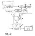
- FIG. 4 aillustrates a schematic diagram of a physiological monitor to compute primary physiological signals.
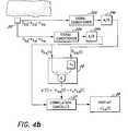
- FIG. 4 billustrates a schematic diagram of a physiological monitor to compute secondary signals.
- FIG. 5 aillustrates an example of an adaptive noise canceler which could be employed in a physiological monitor, to compute primary physiological signals.
- FIG. 5 billustrates an example of an adaptive noise canceler which could be employed in a physiological monitor, to compute secondary motion artifact signals.
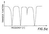
- FIG. 5 cillustrates the transfer function of a multiple notch filter.
- FIG. 6 aillustrates a schematic of absorbing material comprising N constituents within the absorbing material.
- FIG. 6 billustrates another schematic of absorbing material comprising N constituents, including one mixed layer, within the absorbing material.
- FIG. 6 cillustrates another schematic of absorbing material comprising N constituents, including two mixed layers, within the absorbing material.
- FIG. 7 aillustrates a schematic diagram of a monitor, to compute primary and secondary signals in accordance with one aspect of the present invention.
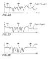
- FIG. 7 billustrates the ideal correlation canceler energy or power output as a function of the signal coefficients r 1 , r 2 , . . . r n .
- FIG. 7 cillustrates the non-ideal correlation canceler energy or power output as a function of the signal coefficients r 1 , r 2 , . . . r n .
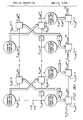
- FIG. 8is a schematic model of a joint process estimator comprising a least-squares lattice predictor and a regression filter.
- FIG. 8 ais a schematic model of a joint process estimator comprising a QRD least-squares lattice (LSL) predictor and a regression filter.
- LSLleast-squares lattice
- FIG. 9is a flowchart representing a subroutine for implementing in software a joint process estimator as modeled in FIG. 8 .
- FIG. 9 ais a flowchart representing a subroutine for implementing in software a joint process estimator as modeled in FIG. 8 a.
- FIG. 10is a schematic model of a joint process estimator with a least-squares lattice predictor and two regression filters.
- FIG. 10 ais a schematic model of a joint process estimator with a QRD least-squares lattice predictor and two regression filters.
- FIG. 11is an example of a physiological monitor in accordance with the teachings of one aspect of the present invention.
- FIG. 11 aillustrates an example of a low noise emitter current driver with accompanying digital to analog converter.
- FIG. 12illustrates the front end analog signal conditioning circuitry and the analog to digital conversion circuitry of the physiological monitor of FIG. 11 .
- FIG. 13illustrates further detail of the digital signal processing circuitry of FIG. 11 .
- FIG. 14illustrates additional detail of the operations performed by the digital signal processing circuitry of FIG. 11 .
- FIG. 15illustrates additional detail regarding the demodulation module of FIG. 14 .
- FIG. 18illustrates a block diagram of the operations of one embodiment of the saturation transform module of FIG. 14 .
- FIG. 20illustrates a block diagram of the operations of the pulse rate calculation module of FIG. 14 .
- FIG. 21illustrates a block diagram of the operations of the motion artifact suppression module of FIG. 20 .
- FIG. 22illustrates a saturation transform curve in accordance with the principles of the present invention.
- FIG. 23illustrates a block diagram of an alternative embodiment to the saturation transform in order to obtain a saturation value.
- FIGS. 25A-25Cillustrate yet another alternative embodiment in order to obtain the saturation.
- the measured signalcomprises a primary portion s ⁇ a (t) and a secondary portion n ⁇ a (t).
- FIG. 28illustrates the secondary reference n′(t) determined by a processor of the present invention.
- FIG. 31depicts a set of 3 concentric electrodes, i.e., a tripolar electrode sensor, to derive electrocardiography (ECG) signals, denoted as S 1 , S 2 and S 3 , for use with the present invention.
- ECGelectrocardiography
- Each of the ECG signalscontains a primary portion and a secondary portion.
- the present inventioninvolves a system which utilizes first and second measured signals that each contain a primary signal portion and a secondary signal portion.
- the output of the systemprovides a good approximation n′′(t) to the secondary signal portion n(t) or a good approximation s′′(t) to the primary signal portion s(t).
- the system of the present inventionis particularly useful where the primary and/or secondary signal portion n(t) may contain one or more of a constant portion, a predictable portion, an erratic portion, a random portion, etc.
- the primary signal approximation s′′(t) or secondary signal approximation n′′(t)is derived by removing as many of the secondary signal portions n(t) or primary signal portions s(t) from the composite signal S(t) as possible. The remaining signal forms either the primary signal approximation s′′(t) or secondary signal approximation n′′(t), respectively.
- the constant portion and predictable portion of the secondary signal n(t)are easily removed with traditional filtering techniques, such as simple subtraction, low pass, band pass, and high pass filtering.
- the erratic portionis more difficult to remove due to its unpredictable nature. If something is known about the erratic signal, even statistically, it could be removed, at least partially, from the measured signal via traditional filtering techniques. However, often no information is known about the erratic portion of the secondary signal n(t). In this case, traditional filtering techniques are usually insufficient.
- the first and second measured signals S 1 and S 2are related by correlation coefficients r a and r v as defined above. The use and selection of these coefficients is described in further detail below.
- this signal modelis used in combination with a correlation canceler, such as an adaptive noise canceler, to remove or derive the erratic portion of the measured signals.
- a correlation cancelersuch as an adaptive noise canceler
- a correlation cancelerhas two signal inputs and one output.
- One of the inputsis either the secondary reference n′(t) or the primary reference s′(t) which are correlated, respectively, to the secondary signal portions n(t) and the primary signal portions s(t) present in the composite signal S(t).
- the other inputis for the composite signal S(t).
- the output of the correlation canceler s′′(t) or n′′(t)corresponds, respectively, to the primary signal s(t) or the secondary signal n(t) portions only.
- a secondary reference n′(t) or a primary reference s′(t)is determined from two composite signals measured simultaneously, or nearly simultaneously, at two different wavelengths, ⁇ a and ⁇ b.
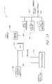
- FIGS. 4 a and 4 bA block diagram of a generic monitor incorporating a signal processor according to the present invention, and a correlation canceler is shown in FIGS. 4 a and 4 b .
- Two measured signals, S ⁇ a (t) and S ⁇ b (t)are acquired by a detector 20 .
- Each signalis conditioned by a signal conditioner 22 a and 22 b . Conditioning includes, but is not limited to, such procedures as filtering the signals to remove constant portions and amplifying the signals for ease of manipulation.
- the signalsare then converted to digital data by an analog-to-digital converter 24 a and 24 b .
- the first measured signal S ⁇ a (t)comprises a first primary signal portion, labeled herein s ⁇ a (t), and a first secondary signal portion, labeled herein n ⁇ a (t).
- the second measured signal S ⁇ b (t)is at least partially correlated to the first measured signal S ⁇ a (t) and comprises a second primary signal portion, labeled herein s ⁇ b (t), and a second secondary signal portion, labeled herein n ⁇ b (t).
- the first and second secondary signal portions, n ⁇ a (t) and n ⁇ b (t)are uncorrelated and/or erratic with respect to the primary signal portions s ⁇ a (t) and s ⁇ b (t).
- the secondary signal portions n ⁇ a (t) and n ⁇ b (t)are often caused by motion of a patient in physiological measurements.
- the signals S ⁇ a (t) and S ⁇ b (t)are input to a reference processor 26 .
- the signal coefficient factors r a and r vare determined to cause either the primary signal portions s ⁇ a (t) and s ⁇ b (t) or the secondary signal portions n ⁇ a (t) and n ⁇ b (t) to cancel, respectively, when the two signals s ⁇ a (t) and s ⁇ b (t) are subtracted.
- a reference signal n′(t) or s′(t)is input, along with one of the measured signals S ⁇ a (t) or S ⁇ b (t), to a correlation canceler 27 which uses the reference signal n′(t) or s′(t) to remove either the secondary signal portions n ⁇ a (t) or n ⁇ b (t) or the primary signal portions s ⁇ a (t) or s ⁇ b (t) from the measured signal S ⁇ a (t) or S ⁇ b (t).
- the output of the correlation canceler 27is a good primary signal approximation s′′(t) or secondary signal approximation n′′(t). In one embodiment, the approximation s′′(t) or n′′(t) is displayed on a display 28 .
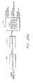
- an adaptive noise canceler 30is employed as the correlation canceler 27 , to remove either one of the erratic, secondary signal portions n ⁇ a (t) and n ⁇ b (t) from the first and second signals S ⁇ a (t) and S ⁇ b (t).
- the adaptive noise canceler 30 in FIG. 5 ahas as one input a sample of the secondary reference n′(t) which is correlated to the secondary signal portions n ⁇ a (t) and n ⁇ b (t).
- the secondary reference n′(t)is determined from the two measured signals S ⁇ a (t) and S ⁇ b (t) by the processor 26 of the present invention as described herein.
- the adaptive noise canceler 30functions to remove frequencies common to both the reference n′(t) or s′(t) and the measured signal S ⁇ a (t) or S ⁇ b (t). Since the reference signals are correlated to either the secondary signal portions n ⁇ a (t) and n ⁇ b (t) or the primary signal portions s ⁇ a (t) and s ⁇ b (t), the reference signals will be correspondingly erratic or well behaved.
- the adaptive noise canceler 30acts in a manner which may be analogized to a dynamic multiple notch filter based on the spectral distribution of the reference signal n′(t) or s′(t).
- FIG. 5 cillustrates an exemplary transfer function of a multiple notch filter.
- the notches, or dips in the amplitude of the transfer function,indicate frequencies which are attenuated or removed when a signal passes through the notch filter.
- the output of the notch filteris the composite signal having frequencies at which a notch is present removed.
- the frequencies at which notches are presentchange continuously based upon the inputs to the adaptive noise canceler 30 .
- the adaptive noise canceler 30( FIGS. 5 a and 5 b ) produces an output signal, labeled herein as s′′ ⁇ a (t), s′′ ⁇ b (t), n′′ ⁇ a (t) or n′′ ⁇ b (t) which is fed back to an internal processor 32 within the adaptive noise canceler 30 .
- the internal processor 32automatically adjusts its own transfer function according to a predetermined algorithm such that the output of the internal processor 32 labeled b ⁇ (t) in FIG. 5 a and c ⁇ (t) in FIG. 5 b , closely resembles either the secondary signal portion n ⁇ a (t) or n ⁇ b (t) or the primary signal portion s ⁇ a (t) or s ⁇ b (t).
- the internal processoroptimizes s′′ ⁇ a (t) or s′′ ⁇ b (t) such that s′′ ⁇ a (t) or s′′ ⁇ b (t) is approximately equal to the primary signal s ⁇ a (t) or s ⁇ b (t), respectively.
- the internal processoroptimizes n′′ ⁇ a (t) or n′′ ⁇ b (t) such that n′′ ⁇ a (t) or n′′ ⁇ b (t) is approximately equal to the secondary signal portion n ⁇ a (t) or n ⁇ b (t), respectively.
- One algorithm which may be used for the adjustment of the transfer function of the internal processor 32is a least-squares algorithm, as described in Chapter 6 and Chapter 12 of the book Adaptive Signal Processing by Bernard Widrow and Samuel Stearns, published by Prentice Hall, copyright 1985. This entire book, including Chapters 6 and 12, is hereby incorporated herein by reference.
- Adaptive processors 30 in FIGS. 5 a and 5 bhave been successfully applied to a number of problems including antenna sidelobe canceling, pattern recognition, the elimination of periodic interference in general, and the elimination of echoes on long distance telephone transmission lines.
- considerable ingenuityis often required to find a suitable reference signal n′(t) or s′(t) since the portions n ⁇ a (t), n ⁇ b (t), s ⁇ a (t) and s ⁇ b (t) cannot easily be separated from the measured composite signals S ⁇ a (t) and S ⁇ b (t). If either the actual secondary portion n ⁇ a (t) or n ⁇ b (t) or the primary signal portion s ⁇ a (t) or s ⁇ b (t) were a priori available, techniques such as correlation cancellation would not be necessary.
- the measured signals S ⁇ a (t) and S ⁇ b (t)are transformed to eliminate, respectively, the primary or secondary signal components.
- a correlation cancelersuch as an adaptive noise canceler.
- a correlation cancelersuch as an adaptive noise canceler.
- Correlation cancelingis particularly useful in a large number of measurements generally described as absorption measurements.
- An example of an absorption type monitor which can advantageously employ correlation canceling, such as adaptive noise canceling, based upon a reference n′(t) or s′(t) determined by a processor of the present inventionis one which determines the concentration of an energy absorbing constituent within an absorbing material when the material is subject to change. Such changes can be caused by forces about which information is desired or primary, or alternatively, by random or erratic secondary forces such as a mechanical force on the material. Random or erratic interference, such as motion, generates secondary components in the measured signal. These secondary components can be removed or derived by the correlation canceler if a suitable secondary reference n′(t) or primary reference s′(t) is known.
- FIG. 6 aA schematic N constituent absorbing material comprising a container 42 having N different absorbing constituents, labeled A 1 , A 2 , A 3 , . . . A N , is shown in FIG. 6 a .
- the constituents A 1 through A N in FIG. 6 aare arranged in a generally orderly, layered fashion within the container 42 .
- An example of a particular type of absorptive systemis one in which light energy passes through the container 42 and is absorbed according to the generalized Beer-Lambert Law of light absorption. For light of wavelength ⁇ a, this attenuation may be approximated by:
- the absorption coefficients ⁇ 1 through ⁇ Nare known values which are constant at each wavelength. Most concentrations c 1 (t) through c N (t) are typically unknown, as are most of the optical path lengths x i (t) of each layer. The total optical path length is the sum of each of the individual optical path lengths x i (t) of each layer.
- the optical path length of each layer, x i (t),is generally constant. This results in generally constant attenuation of the optical energy and thus, a generally constant offset in the measured signal.
- this offset portion of the signalis of little interest since knowledge about a force which perturbs the material is usually desired. Any signal portion outside of a known bandwidth of interest, including the constant undesired signal portion resulting from the generally constant absorption of the constituents when not subject to change, is removed. This is easily accomplished by traditional band pass filtering techniques.
- each layer of constituentsmay be affected by the perturbation differently than other layers.
- Some perturbations of the optical path lengths of each layer x i (t)may result in excursions in the measured signal which represent desired or primary information. Other perturbations of the optical path length of each layer x i (t) cause undesired or secondary excursions which mask primary information in the measured signal. Secondary signal components associated with secondary excursions must also be removed to obtain primary information from the measured signal. Similarly, the ability to compute secondary signal components caused by secondary excursions directly allows one to obtain primary signal components from the measured signal via simple subtraction, or correlation cancellation techniques.
- the correlation cancelermay selectively remove from the composite signal, measured after being transmitted through or reflected from the absorbing material, either the secondary or the primary signal components caused by forces which perturb or change the material differently from the forces which perturbed or changed the material to cause respectively, either the primary or secondary signal component.
- the portion of the measured signal which is deemed to be the primary signal s ⁇ a (t)is the attenuation term ⁇ 5 c 5 x 5 (t) associated with a constituent of interest, namely A 5 , and that the layer of constituent A 5 is affected by perturbations different than each of the layers of other constituents A 1 through A 4 and A 6 through A N .
- the secondary signal component n ⁇ a (t)can be either removed or derived via a correlation canceler, such as an adaptive noise canceler, having as one input, respectively, a secondary reference n′(t) or a primary reference s′(t) determined by a processor of the present invention as long as the perturbation on layers other than the layer of constituent A 5 is different than the perturbation on the layer of constituent A 5 .
- the correlation canceleryields a good approximation to either the primary signal s ⁇ a (t) or the secondary signal n ⁇ a (t).
- the concentration of the constituent of interest, c 5 (t)can often be determined since in some physiological measurements, the thickness of the primary signal component, x 5 (t) in this example, is known or can be determined.
- the correlation cancelerutilizes either the secondary reference n′(t) or the primary reference s′(t) determined from two substantially simultaneously measured signals S ⁇ a (t) and S ⁇ b (t).
- S ⁇ a (t)is determined as above in equation (7).
- S ⁇ b (t)is determined similarly at a different wavelength ⁇ b.
- the signals S ⁇ a (t) and S ⁇ b (t)can then be written (logarithm converted) as:
- a sample of either the secondary reference n′(t) or the primary reference s′(t), and a sample of either measured signal S ⁇ a (t) or S ⁇ b (t),are input to a correlation canceler 27 , such as an adaptive noise canceler 30 , an example of which is shown in FIGS. 5 a and 5 b and a preferred example of which is discussed herein under the heading PREFERRED CORRELATION CANCELER USING A JOINT PROCESS ESTIMATOR IMPLEMENTATION.
- the correlation canceler 27removes either the secondary portion n ⁇ a (t) or n ⁇ b (t), or the primary portions, s ⁇ a (t) or s ⁇ b (t), of the measured signal yielding a good approximation to either the primary signals s′′ ⁇ a (t) ⁇ 5, ⁇ a c 5 x 5 (t) or s′′ ⁇ b (t) ⁇ 5, ⁇ b c 5 x 5 (t) or the secondary signals n′′ ⁇ a (t) ⁇ n ⁇ a (t) or n′′ ⁇ b (t) ⁇ n ⁇ b (t).
- the concentration c 5 (t)may then be determined from the approximation to the primary signal s′′ ⁇ a (t) or s′′ ⁇ b (t) according to: c 5 ( t ) ⁇ s′′ ⁇ a ( t )/ ⁇ 5, ⁇ a x 5 ( t ) (17a) or c 5 ( t ) ⁇ s′′ ⁇ b ( t )/ ⁇ 5, ⁇ b x 5 ( t ) (17b)
- the absorption coefficientsare constant at each wavelength ⁇ a and ⁇ b and the thickness of the primary signal component, x 5 (t) in this example, is often known or can be determined as a function of time, thereby allowing calculation of the concentration c 5 (t) of constituent A 5 .
- FIG. 6 banother material having N different constituents arranged in layers is shown.
- Thisis analogous to combining the layers of constituents A 5 and A 6 in FIG. 6 a .
- a combination of layers, such as the combination of layers of constituents A 5 and A 6is feasible when the two layers are under the same total forces which result in the same change of the optical path lengths x 5 (t) and x 6 (t) of the layers.
- concentration or the saturationi.e., a percent concentration
- a determination of the concentration or the saturation of a constituent within a given volumemay be made with any number of constituents in the volume subject to the same total forces and therefore under the same perturbation or change.
- To determine the saturation of one constituent in a volume comprising many constituentsas many measured signals as there are constituents which absorb incident light energy are necessary. It will be understood that constituents which do not absorb light energy are not consequential in the determination of saturation.
- concentrationas many signals as there are constituents which absorb incident light energy are necessary as well as information about the sum of concentrations.
- the primary signals s ⁇ a (t) and s ⁇ b (t)comprise terms related to both A 5 and A 6 so that a determination of the concentration or saturation of A 5 or A 6 in the volume may be made.
- the measured signals S ⁇ a (t) and S ⁇ b (t)can be written (logarithm converted) as:
- the primary signals s ⁇ a (t) and s ⁇ b (t)again comprise terms related to both A 5 and A 6 and portions of the secondary signals n ⁇ a (t) and n ⁇ b (t) comprise terms related to both A 3 and A 4 .
- the primary and secondary signals according to this modelmay be written as:
- n ⁇ ⁇ ⁇ b ⁇ ( t )[ ⁇ 5 , ⁇ ⁇ ⁇ b ⁇ c 3 + ⁇ 6 , ⁇ ⁇ ⁇ b ⁇ c 4 ] ⁇ ⁇ x 3 , 4 ⁇ ( t ) + n ⁇ ⁇ ⁇ b ⁇ ( t ) ( 21 ⁇ c )
- signals n ⁇ a (t) and n ⁇ b (t)are similar to the secondary signals n ⁇ a (t) and n ⁇ b (t) except for the omission of the 3, 4 layer.
- any signal portions whether primary or secondary, outside of a known bandwidth of interest, including the constant undesired secondary signal portion resulting from the generally constant absorption of the constituents when not under perturbation,should be removed to determine an approximation to either the primary signal or the secondary signal within the bandwidth of interest. This is easily accomplished by traditional band pass filtering techniques. As in the previous example, it is often the case that the total perturbation or change affecting the layers associated with the secondary signal components is caused by random or erratic forces, causing the thickness of each layer, or the optical path length of each layer, x i (t), to change erratically, producing a random or erratic secondary signal component n ⁇ a (t).
- the secondary signal component n ⁇ a (t)can be removed or derived via a correlation canceler, such as an adaptive noise canceler, having as one input a secondary reference n′(t) or a primary reference s′(t) determined by a processor of the present invention as long as the perturbation in layers other than the layer of constituents A 5 and A 6 is different than the perturbation in the layer of constituents A 5 and A 6 .
- a correlation cancelersuch as an adaptive noise canceler
- Either the erratic secondary signal components n ⁇ a (t) and n ⁇ b (t) or the primary components s ⁇ a (t) and s ⁇ b (t)may advantageously be removed from equations (18) and (19), or alternatively equations (20) and (21), by a correlation canceler.
- the correlation canceleragain, requires a sample of either the primary reference s′(t) or the secondary reference n′(t) and a sample of either of the composite signals S ⁇ a (t) or S ⁇ b (t) of equations (18) and (19).
- the approximations to either the primary signals s ⁇ a (t) and s ⁇ b (t) or the secondary signals n ⁇ a (t) and n ⁇ b (t), found by the correlation canceler for a substantially immediately preceding set of samples of the measured signals S ⁇ a (t) and S ⁇ b (t)are used in a processor of the present invention for calculating the proportionality constants, r a and r v , for the next set of samples of the measured signals S ⁇ a (t) and S ⁇ b (t).
- initial proportionality coefficientscan be determined as further explained below. It is not necessary for the patient to remain motionless even for an initialization period.
- a correlation cancelermay be utilized with a secondary reference n′(t) or a primary reference s′(t).
- signal coefficients r a and r vare determined from the plurality of assumed signal coefficients r 1 , r 2 , . . . r n .
- the coefficients r a and r vare selected such that they cause either the primary signal portions s ⁇ a (t) and s ⁇ b (t) or the secondary signal portions n ⁇ a (t) and n ⁇ b (t) to cancel or nearly cancel when they are substituted into the reference function R′(r, t), e.g.
- coefficients r a and r vare selected at values which reflect the minimum of correlation between the primary signal portions and the secondary signal portions.
- One approach to determine the signal coefficients r a and r v from the plurality of coefficients r 1 , r 2 , . . . r nemploys the use of a correlation canceler 27 , such as an adaptive noise canceler, which takes a first input which corresponds to one of the measured signals S ⁇ a (t) or S ⁇ b (t) and takes a second input which corresponds to successively each one of the plurality of reference signals R′(r 1 , t), R′(r 2 , t), . . . , R′(r n , t) as shown in FIG. 7 a .
- a correlation canceler 27such as an adaptive noise canceler
- the corresponding output of the correlation canceler 27is input to a “squares” operation 28 which squares the output of the correlation canceler 27 .
- the output of the squares operation 28is provided to an integrator 29 for forming a cumulative output signal (a summation of the squares).
- the cumulative output signalis subsequently input to an extremum detector 31 .
- the purpose of the extremum detector 31is to chose signal coefficients r a and r v from the set r 1 , r 2 , . . . r n by observing which provide a maximum in the cumulative output signal as in FIGS.
- coefficients which provide a maximum integrated output, such as energy or power, from the correlation canceler 27correspond to the signal coefficients r a and r v which relate to a minimum correlation between the primary signal portions and the secondary signal portions in accordance with the signal model of the present invention.
- the time variable, t, of the correlation canceler output C(S ⁇ a (t), R′(r j , t))may be eliminated by computing its energy or power.
- the energy of the correlation canceler outputis given by
- the correlation canceler energy outputis
- discrete time measurement signalsmay be employed as well as continuous time measurement signals.
- a system which performs a discrete transforme.g., a saturation transform in the present example
- integration approximation methodssuch as the trapezoid rule, midpoint rule, Tick's rule, Simpson's approximation or other techniques may be used to compute the correlation canceler energy or power output.
- the energy output of the correlation cancelermay be written, using the trapezoid rule, as
- the energy functions given above, and shown in FIG. 7 bindicate that the correlation canceler output is usually zero due to correlation between the measured signal S ⁇ a (t) or S ⁇ b (t) and many of the plurality of reference signals R′(r 1 , t), R′(r 2 , t), . . . , R′(r n , t).
- the energy functionsare non zero at values of r j which correspond to cancellation of either the primary signal portions s ⁇ a (t) and s ⁇ b (t) or the secondary signal portions n ⁇ a (t) and n ⁇ b (t) in the reference signal R′(r j , t). These values correspond to the signal coefficients r a and r v .
- the correlation canceler energy curves depicted in FIG. 7 bwill not consist of infinitely narrow delta functions but will have finite width associated with them as depicted in FIG. 7 c.
- reference signal techniques together with a correlation cancellationcan be employed to decompose a signal into two or more signal components each of which is related by a ratio.
- the correlation cancelercan be implemented in either hardware or software.
- the preferred implementation of a correlation canceleris that of an adaptive noise canceler using a joint process estimator.
- the least mean squares (LMS) implementation of the internal processor 32 described above in conjunction with the adaptive noise canceler of FIG. 5 a and FIG. 5 bis relatively easy to implement, but lacks the speed of adaptation desirable for most physiological monitoring applications of the present invention.
- LMSleast mean squares
- a faster approach for adaptive noise cancelingcalled a least-squares lattice joint process estimator model, is used in one embodiment.
- a joint process estimator 60is shown diagrammatically in FIG. 8 and is described in detail in Chapter 9 of Adaptive Filter Theory by Simon Haykin, published by Prentice-Hall, copyright 1986. This entire book, including Chapter 9, is hereby incorporated herein by reference.
- the function of the joint process estimatoris to remove either the secondary signal portions n ⁇ a (t) or n ⁇ b (t) or the primary signal portions s ⁇ a (t) or s ⁇ b (t) from the measured signals S ⁇ a (t) or S ⁇ b (t), yielding either a primary signal approximation s′′ ⁇ a (t) or s′′ ⁇ b (t) or a secondary signal approximation n′′ ⁇ a (t) or n′′ ⁇ b (t).
- the joint process estimatorestimates either the value of the primary signals s ⁇ a (t) or s ⁇ b (t) or the secondary signals n ⁇ a (t) or n ⁇ b (t).
- the inputs to the joint process estimator 60are either the secondary reference n′(t) or the primary reference s′(t) and the composite measured signal S ⁇ a (t) or S ⁇ b (t).
- the outputis a good approximation to the signal S ⁇ a (t) or S ⁇ b (t) with either the secondary signal or the primary signal removed, i.e. a good approximation to either s ⁇ a (t), s ⁇ b (t), n ⁇ a (t) or n ⁇ b (t).
- the joint process estimator 60 of FIG. 8utilizes, in conjunction, a least square lattice predictor 70 and a regression filter 80 .
- Either the secondary reference n′(t) or the primary reference s′(t)is input to the least square lattice predictor 70 while the measured signal S ⁇ a (t) or S ⁇ b (t) is input to the regression filter 80 .
- S ⁇ a (t)will be the measured signal from which either the primary portion s ⁇ a (t) or the secondary portion n ⁇ a (t) will be estimated by the joint process estimator 60 .
- S ⁇ b (t)could also be input to the regression filter 80 and the primary portion s ⁇ b (t) or the secondary portion n ⁇ b (t) of this signal could be estimated.
- the joint process estimator 60removes all frequencies that are present in both the reference n′(t) or s′(t), and the measured signal S ⁇ a (t).
- the secondary signal portion n ⁇ a (t)usually comprises frequencies unrelated to those of the primary signal portion s ⁇ a (t). It is improbable that the secondary signal portion n ⁇ a (t) would be of exactly the same spectral content as the primary signal portion s ⁇ a (t). However, in the unlikely event that the spectral content of s ⁇ a (t) and n ⁇ a (t) are similar, this approach will not yield accurate results.
- the joint process estimator 60compares the reference input signal n′(t) or s′(t), which is correlated to either the secondary signal portion n ⁇ a (t) or the primary signal portion s ⁇ a (t), and input signal S ⁇ a (t) and removes all frequencies which are identical.
- the joint process estimator 60acts as a dynamic multiple notch filter to remove those frequencies in the secondary signal component n ⁇ a (t) as they change erratically with the motion of the patient or those frequencies in the primary signal component s ⁇ a (t) as they change with the arterial pulsation of the patient.
- the output s′′ ⁇ a (t) or n′′ ⁇ a (t) of the joint process estimator 60is a very good approximation to either the primary signal s ⁇ a (t) or the secondary signal n ⁇ a (t).
- the joint process estimator 60can be divided into stages, beginning with a zero-stage and terminating in an m th -stage, as shown in FIG. 8 . Each stage, except for the zero-stage, is identical to every other stage.
- the zero-stageis an input stage for the joint process estimator 60 .
- the first stage through the m th -stagework on the signal produced in the immediately previous stage, i.e., the (m ⁇ 1) th -stage, such that a good primary signal approximation s′′ ⁇ a (t) or secondary signal approximation n′′ ⁇ a (t) is produced as output from the m th -stage.
- the least-squares lattice predictor 70comprises registers 90 and 92 , summing elements 100 and 102 , and delay elements 110 .
- the registers 90 and 92contain multiplicative values of a forward reflection coefficient ⁇ f,m (t) and a backward reflection coefficient ⁇ b,m (t) which multiply the reference signal n′(t) or s′(t) and signals derived from the reference signal n′(t) or s′(t).
- Each stage of the least-squares lattice predictoroutputs a forward prediction error f m (t) and a backward prediction error b m (t).
- the subscript mis indicative of the stage.
- the sample of the reference signal n′(t) or s′(t)is input to the least-squares lattice predictor 70 .
- the zero-stage forward prediction error f 0 (t) and the zero-stage backward prediction error b 0 (t)are set equal to the reference signal n′(t) or s′(t).
- the backward prediction error b 0 (t)is delayed by one sample period by the delay element 110 in the first stage of the least-squares lattice predictor 70 .
- the immediately previous value of the reference n′(t) or s′(t)is used in calculations involving the first-stage delay element 110 .
- the zero-stage forward prediction erroris added to the negative of the delayed zero-stage backward prediction error b 0 (t ⁇ 1) multiplied by the forward reflection coefficient value ⁇ f,1 (t) register 90 value, to produce a first-stage forward prediction error f 1 (t).
- the zero-stage forward prediction error f 0 (t)is multiplied by the backward reflection coefficient F b,1 (t) register 92 value and added to the delayed zero-stage backward prediction error b 0 (t ⁇ 1) to produce a first-stage backward prediction error b 1 (t).
- the previous forward and backward prediction error values, f m ⁇ 1 (t) and b m ⁇ 1 (t ⁇ 1), the backward prediction error being delayed by one sample period,are used to produce values of the forward and backward prediction errors for the present stage, f m (t) and b m (t).
- the backward prediction error b m (t)is fed to the concurrent stage, m, of the regression filter 80 . There it is input to a register 96 , which contains a multiplicative regression coefficient value ⁇ m, ⁇ a (t).
- a register 96which contains a multiplicative regression coefficient value ⁇ m, ⁇ a (t).
- the zero-stage backward prediction error b 0 (t)is multiplied by the zero-stage regression coefficient ⁇ 0, ⁇ a (t) register 96 value and subtracted from the measured value of the signal S ⁇ a (t) at a summing element 106 to produce a first stage estimation error signal e 1, ⁇ a (t).
- the first-stage estimation error signal e 1, ⁇ a (t)is a first approximation to either the primary signal or the secondary signal.
- This first-stage estimation error signal e 1, ⁇ a (t)is input to the first-stage of the regression filter 80 .
- the first-stage backward prediction error b 1 (t), multiplied by the first-stage regression coefficient ⁇ 1, ⁇ a (t) register 96 valueis subtracted from the first-stage estimation error signal e 1, ⁇ a (t) to produce the second-stage estimation error e 2, ⁇ a (t).
- the second-stage estimation error signal e 2, ⁇ a (t)is a second, somewhat better approximation to either the primary signal s ⁇ a (t) or the secondary signal n ⁇ a (t).
- a number of intermediate variablesare required to calculate the forward reflection coefficient ⁇ f,m (t), the backward reflection coefficient ⁇ b,m (t), and the regression coefficient ⁇ m, ⁇ a (t) register 90 , 92 , and 96 values.
- Intermediate variablesinclude a weighted sum of the forward prediction error squares I m (t), a weighted sum of the backward prediction error squares ⁇ m (t), a scalar parameter ⁇ m (t), a conversion factor ⁇ m (t), and another scalar parameter ⁇ m, ⁇ a (t).
- the weighted sum of the forward prediction errors I m (t)is defined as:
- the weighted sum of the backward prediction errors ⁇ m (t)is defined as:
- ⁇ without a wavelength identifier, a or bis a constant multiplicative value unrelated to wavelength and is typically less than or equal to one, i.e., ⁇ 1.
- the operation of the joint process estimator 60is as follows.
- a simultaneous sample of the measured signal S ⁇ a (t) or S ⁇ b (t) and either the secondary reference n′(t) or the primary reference s′(t)are input to the joint process estimator 60 , as shown in FIG. 8 .
- Forward reflection coefficient ⁇ f,m (t), backward reflection coefficient ⁇ b,m (t), and regression coefficient ⁇ m, ⁇ a (t) register 90 , 92 and 96 values in each stage thereafterare set according to the output of the previous stage.
- the forward reflection coefficient ⁇ f,1 (t), backward reflection coefficient ⁇ b,1 (t), and regression coefficient ⁇ 1, ⁇ a (t) register 90 , 92 and 96 values in the first stageare thus set according to the algorithm using values in the zero-stage of the joint process estimator 60 .
- a next set of samplesincluding a sample of the measured signal S ⁇ a (t) and a sample of either the secondary reference n′(t) or the primary reference s′(t), are input to the joint process estimator 60 .
- the re-initialization processdoes not re-occur, such that the forward and backward reflection coefficient ⁇ f,m (t) and ⁇ b,m (t) register 90 , 92 values and the regression coefficient ⁇ m, ⁇ a (t) register 96 value reflect the multiplicative values required to estimate either the primary signal portion s ⁇ a (t) or the secondary signal portion n ⁇ a (t) of the sample of S ⁇ a (t) input previously.
- information from previous samplesis used to estimate either the primary or secondary signal portion of a present set of samples in each stage.
- a normalized joint process estimatoris used. This version of the joint process estimator normalizes several variables of the above-described joint process estimator such that the normalized variables fall between ⁇ 1 and 1.
- the derivation of the normalized joint process estimatoris motivated in the Haykin text as problem 12 on page 640 by redefining the variables defined according to the following conditions:
- f _ m ⁇ ( t )f m ⁇ ( t ) m ⁇ ( t ) ⁇ ⁇ m ⁇ ( t - 1 )
- b _ ⁇ ( t )b m ⁇ ( t ) ⁇ m ⁇ ( t ) ⁇ ⁇ m ⁇ ( t )
- _ m ⁇ ( t )⁇ m ⁇ ( t ) m ⁇ ( t ) ⁇ ⁇ m ⁇ ( t - 1 )
- ⁇ _ m - 1 ⁇ ( t )⁇ _ m - 1 ⁇ ( t - 1 ) ⁇ [ 1 -
- 2 ⁇ ⁇ ] 1 / 2 + b _ m - 1 ⁇ ( t - 1 ) ⁇ f _ m - 1 ⁇ ( t ) ⁇ b _ m ⁇ ( t )[ b _ m - 1 ⁇ ( t - 1 ) - ⁇ _ m - 1 ⁇ ( t ) ⁇ f _ m - 1 ⁇ ( t ) ] [ 1 -
- N(t)be defined as the reference noise input at time index n
- U(t)be defined as combined signal plus noise input at time index t the following equations apply (see Haykin, p. 619):
- a normalized joint process estimatorcan be used for a more stable system.
- the correlation cancellationis performed with a QRD algorithm as shown diagrammatically in FIG. 8 a and as described in detail in Chapter 18 of Adaptive Filter Theory by Simon Haykin, published by Prentice-Hall, copyright 1986.
- ⁇ m - 1 ⁇ ( t - 1 )⁇ m - 1 ⁇ ( t - 2 ) +
- ⁇ m ⁇ ( t )⁇ m ⁇ ( t - 1 ) +
- m ⁇ ( t )⁇ 1 / 2 ⁇ ⁇ m 1 / 2 ⁇ ( t - 1 ) ⁇ m 1 / 2 ⁇ ( t ) s b
- a joint process estimator 60 type adaptive noise canceleris generally implemented via a software program having an iterative loop.
- One iteration of the loopis analogous to a single stage of the joint process estimator as shown in FIG. 8 .
- a loopis iterated m times, it is equivalent to an m stage joint process estimator 60 .
- FIG. 9A flow chart of a subroutine to estimate the primary signal portion s ⁇ a (t) or the secondary signal portion n ⁇ a (t) of a measured composite signal, S ⁇ a (t) is shown in FIG. 9 .
- the flow chartillustrates the function of a reference processor for determining either the secondary reference n′(t) or the primary reference s′(t).
- the flowchart for the joint process estimatoris implemented in software.
- a one-time initializationis performed when the physiological monitor is powered-on, as indicated by an “INITIALIZE NOISE CANCELER” action block 120 .
- the initializationsets all registers 90 , 92 , and 96 and delay element variables 110 to the values described above in equations (46) through (50).
- a set of simultaneous samples of the composite measured signals S ⁇ a (t) and S ⁇ b (t)is input to the subroutine represented by the flowchart in FIG. 9 .
- a time update of each of the delay element program variablesoccurs, as indicated in a “TIME UPDATE OF [Z ⁇ 1 ] ELEMENTS” action block 130 .
- the value stored in each of the delay element variables 110is set to the value at the input of the delay element variable 110 .
- the zero-stage backward prediction error b 0 (t)is stored as the first-stage delay element variable
- the first-stage backward prediction error b 1 (t)is stored as the second-stage delay element variable, and so on.
- the reference signalis obtained using the ratiometric or the constant saturation methods described above. This is indicated by a “CALCULATE REFERENCE [n′(t) or s′(t)] FOR TWO MEASURED SIGNAL SAMPLES” action block 140 .
- a zero-stage order updateis performed next as indicated in a “ZERO-STAGE UPDATE” action block 150 .
- the zero-stage backward prediction error b 0 (t), and the zero-stage forward prediction error f 0 (t)are set equal to the value of the reference signal n′(t) or s′(t). Additionally, the weighted sum of the forward prediction errors ⁇ m (t) and the weighted sum of backward prediction errors ⁇ m (t) are set equal to the value defined in equations (47) and (48).
- a maximum value of mdefining the total number of stages to be used by the subroutine corresponding to the flowchart in FIG. 9 , is also defined.
- the loopis constructed such that it stops iterating once a criterion for convergence upon a best approximation to either the primary signal or the secondary signal has been met by the joint process estimator 60 .
- the forward and backward reflection coefficient ⁇ f,m (t) and ⁇ b,m (t) register 90 and 92 values in the least-squares lattice filterare calculated first, as indicated by the “ORDER UPDATE MTH CELL OF LSL-LATTICE” action block 170 in FIG. 9 .
- Thisrequires calculation of intermediate variable and signal values used in determining register 90 , 92 , and 96 values in the present stage, the next stage, and in the regression filter 80 .
- regression filter register 96 value ⁇ m, ⁇ a (t)is performed next, indicated by the “ORDER UPDATE MTH STAGE OF REGRESSION FILTER(S)” action block 180 .
- convergenceis determined by checking if the weighted sums of the forward and backward prediction errors ⁇ m (t) and ⁇ m (t) are less than a small positive number.
- An outputis calculated next, as indicated by a “CALCULATE OUTPUT” action block 200 .
- the outputis a good approximation to either the primary signal or secondary signal, as determined by the reference processor 26 and joint process estimator 60 subroutine corresponding to the flow chart of FIG. 9 . This is displayed (or used in a calculation in another subroutine), as indicated by a “TO DISPLAY” action block 210 .
- a new set of samples of the two measured signals s ⁇ a (t) and s ⁇ b (t)is input to the processor and joint process estimator 60 adaptive noise canceler subroutine corresponding to the flowchart of FIG. 9 and the process reiterates for these samples. Note, however, that the initialization process does not re-occur.
- New sets of measured signal samples s ⁇ a (t) and s ⁇ b (t)are continuously input to the reference processor 26 and joint process estimator adaptive noise canceler subroutine.
- the outputforms a chain of samples which is representative of a continuous wave.
- This waveformis a good approximation to either the primary signal waveform s ⁇ a (t) or the secondary waveform n ⁇ a (t) at wavelength ⁇ a.
- the waveformmay also be a good approximation to either the primary signal waveform s ⁇ b (t) or the secondary waveform n′′ ⁇ b (t) at wavelength ⁇ b.
- FIG. 9 aA corresponding flowchart for the QRD algorithm of FIG. 8 a is depicted in FIG. 9 a , with reference numeral corresponding in number with an ‘a’ extension
- Physiological monitorsmay use the approximation of the primary signals s′′ ⁇ a (t) or s′′ ⁇ b (t) or the secondary signals n′′ ⁇ a (t) or n′′ ⁇ b (t) to calculate another quantity, such as the saturation of one constituent in a volume containing that constituent plus one or more other constituents.
- another quantitysuch as the saturation of one constituent in a volume containing that constituent plus one or more other constituents.
- such calculationsrequire information about either a primary or secondary signal at two wavelengths.
- the constant saturation methodrequires a good approximation of the primary signal portions s ⁇ a (t) and s ⁇ b (t) of both measured signals S ⁇ a (t) and S ⁇ b (t).
- the arterial saturationis determined from the approximations to both signals, i.e.
- the constant saturation methodalso requires a good approximation of the secondary signal portions n ⁇ a (t) or n ⁇ b (t).
- An estimate of the venous saturationmay be determined from the approximations to these signals i.e. n′′ ⁇ a (t) and n′′ ⁇ b (t).
- a joint process estimator 60 having two regression filters 80 a and 80 bis shown in FIG. 10 .
- a first regression filter 80 aaccepts a measured signal S ⁇ a (t).
- a second regression filter 80 baccepts a measured signal S ⁇ b (t) for a use of the constant saturation method to determine the reference signal n′(t) or s′(t).
- the first and second regression filters 80 a and 80 bare independent.
- the backward prediction error b m (t)is input to each regression filter 80 a and 80 b , the input for the second regression filter 80 b bypassing the first regression filter 80 a.
- the second regression filter 80 bcomprises registers 98 , and summing elements 108 arranged similarly to those in the first regression filter 80 a .
- S ⁇ b (t)is input to the second regression filter 80 b .
- the outputis then a good approximation to the primary signal s′′ ⁇ b (t) or secondary signal s′′ ⁇ b (t).
- the addition of the second regression filter 80 bdoes not substantially change the computer program subroutine represented by the flowchart of FIG. 9 .
- an order update of the m th stage of both regression filters 80 a and 80 bis performed. This is characterized by the plural designation in the “ORDER UPDATE OF m th STAGE OF REGRESSION FILTER(S)” activity block 180 in FIG. 9 . Since the regression filters 80 a and 80 b operate independently, independent calculations can be performed in the reference processor and joint process estimator 60 adaptive noise canceler subroutine modeled by the flowchart of FIG. 9 .
- FIG. 10 aAn alternative diagram for the joint process estimator of FIG. 10 , using the QRD algorithm and having two regression filters is shown in FIG. 10 a .
- This type of joint process estimatorwould be used for correlation cancellation using the QRD algorithm described in the Haykin book.
- the saturation of A 5 in a volume containing A 5 and A 6may be calculated according to various known methods.
- Equations (70) and (71)are equivalent to two equations having three unknowns, namely c 5 (t), c 6 (t) and x 5,6 (t).
- the saturationcan be determined by acquiring approximations to the primary or secondary signal portions at two different, yet proximate times t 1 and t 2 over which the saturation of A 5 in the volume containing A 5 and A 6 and the saturation of A 3 in the volume containing A 3 and A 4 does not change substantially.
- a specific example of a physiological monitor utilizing a processor of the present invention to determine a secondary reference n′(t) for input to a correlation canceler that removes erratic motion-induced secondary signal portionsis a pulse oximeter.
- Pulse oximetrymay also be performed utilizing a processor of the present invention to determine a primary signal reference s′(t) which may be used for display purposes or for input to a correlation canceler to derive information about patient movement and venous blood oxygen saturation.
- a pulse oximetertypically causes energy to propagate through a medium where blood flows close to the surface for example, an ear lobe, or a digit such as a finger, a forehead or a fetus' scalp.
- An attenuated signalis measured after propagation through or reflected from the medium.
- the pulse oximeterestimates the saturation of oxygenated blood.
- Freshly oxygenated bloodis pumped at high pressure from the heart into the arteries for use by the body.
- the volume of blood in the arteriesvaries with the heartbeat, giving rise to a variation in absorption of energy at the rate of the heartbeat, or the pulse.
- Oxygen depleted, or deoxygenated, bloodis returned to the heart by the veins along with unused oxygenated blood.
- the volume of blood in the veinsvaries with the rate of breathing, which is typically much slower than the heartbeat.
- venous bloodcauses a low frequency variation in absorption of energy.
- the low frequency variation in absorptionis coupled with the erratic variation in absorption due to motion artifact.
- two light emitting diodesare positioned on one side of a portion of the body where blood flows close to the surface, such as a finger, and a photodetector is positioned on the opposite side of the finger.
- a visible wavelengthpreferably red
- the other LEDemits an infrared wavelength.
- the fingercomprises skin, tissue, muscle, both arterial blood and venous blood, fat, etc., each of which absorbs light energy differently due to different absorption coefficients, different concentrations, different thicknesses, and changing optical pathlengths.
- FIG. 11depicts a general hardware block diagram of a pulse oximeter 299 .
- a sensor 300has two light emitters 301 and 302 such as LED's. One LED 301 emitting light of red wavelengths and another LED 302 emitting light of infrared wavelengths are placed adjacent a finger 310 .
- a photodetector 320which produces an electrical signal corresponding to the attenuated visible and infrared light energy signals is located opposite the LED's 301 and 302 .
- the photodetector 320is connected to front end analog signal conditioning circuitry 330 .
- the front end analog signal conditioning circuitry 330has outputs coupled to analog to digital conversion circuit 332 .
- the analog to digital conversion circuitry 332has outputs coupled to a digital signal processing system 334 .
- the digital signal processing system 334provides the desired parameters as outputs for a display 336 .
- Outputs for displayare, for example, blood oxygen saturation, heart rate, and a clean plethysmographic waveform.
- the signal processing systemalso provides an emitter current control output 337 to a digital-to-analog converter circuit 338 which provides control information for light emitter drivers 340 .
- the light emitter drivers 340couple to the light emitters 301 , 302 .
- the digital signal processing system 334also provides a gain control output 342 for the front end analog signal conditioning circuitry 330 .
- FIG. 11 aillustrates a preferred embodiment for the combination of the emitter drivers 340 and the digital to analog conversion circuit 338 .
- the drivercomprises first and second input latches 321 , 322 , a synchronizing latch 323 , a voltage reference 324 , a digital to analog conversion circuit 325 , first and second switch banks 326 , 327 , first and second voltage to current converters 328 , 329 and the LED emitters 301 , 302 corresponding to the LED emitters 301 , 302 of FIG. 11 .
- the preferred driver depicted in FIG. 11 ais advantageous in that the present inventors recognized that much of the noise in the oximeter 299 of FIG. 11 is caused by the LED emitters 301 , 302 . Therefore, the emitter driver circuit of FIG. 11 a is designed to minimize the noise from the emitters 301 , 302 .
- the first and second input latches 321 , 324are connected directly to the DSP bus. Therefore, these latches significantly minimizes the bandwidth (resulting in noise) present on the DSP bus which passes through to the driver circuitry of FIG. 11 a .
- the output of the first and second input latchesonly changes when these latched detect their address on the DSP bus.
- the first input latchreceives the setting for the digital to analog converter circuit 325 .
- the second input latchreceives switching control data for the switch banks 326 , 327 .
- the synchronizing latchaccepts the synchronizing pulses which maintain synchronization between the activation of emitters 301 , 302 and the
- the voltage referenceis also chosen as a low noise DC voltage reference for the digital to analog conversion circuit 325 .
- the voltage referencehas an lowpass output filter with a very low corner frequency (e.g., 1 Hz in the present embodiment).
- the digital to analog converter 325also has a lowpass filter at its output with a very low corner frequency (e.g., 1 Hz).
- the digital to analog converterprovides signals for each of the emitters 301 , 302 .
- the output of the voltage to current converters 328 , 329are switched such that with the emitters 301 , 302 connected in back-to-back configuration, only one emitter is active an any given time.
- the voltage to current converter for the inactive emitteris switched off at its input as well, such that it is completely deactivated. This reduces noise from the switching and voltage to current conversion circuitry.
- low noise voltage to current convertersare selected (e.g., Op 27 Op Amps), and the feedback loop is configured to have a low pass filter to reduce noise.
- the low pass filtering function of the voltage to current converter 328 , 329has a corner frequency of just above 625 Hz, which is the switching speed for the emitters, as further discussed below. Accordingly, the preferred driver circuit of FIG. 11 a , minimizes the noise of the emitters 301 , 302 .
- the red and infrared light emitters 301 , 302each emits energy which is absorbed by the finger 310 and received by the photodetector 320 .
- the photodetector 320produces an electrical signal which corresponds to the intensity of the light energy striking the photodetector 320 .
- the front end analog signal conditioning circuitry 330receives the intensity signals and filters and conditions these signals as further described below for further processing.
- the resultant signalsare provided to the analog-to-digital conversion circuitry 332 which converts the analog signals to digital signals for further processing by the digital signal processing system 334 .
- the digital signal processing system 334utilizes the two signals in order to provide a what will be called herein a “saturation transform.” It should be understood, that for parameters other than blood saturation monitoring, the saturation transform could be better termed as a concentration transform, in-vivo transform, or the like, depending on the desired parameter.
- saturation transformis used to describe an operation which converts the sample data from time domain to saturation domain values as will be apparent from the discussion below.
- the output of the digital signal processing system 334provides clean plethysmographic waveforms of the detected signals and provides values for oxygen saturation and pulse rate to the display 336 .
- the digital signal processing system 334also provides control for driving the light emitters 301 , 302 with an emitter current control signal on the emitter current control output 337 .
- This valueis a digital value which is converted by the digital-to-analog conversion circuit 338 which provides a control signal to the emitter current drivers 340 .
- the emitter current drivers 340provide the appropriate current drive for the red emitter 301 and the infrared emitter 302 . Further detail of the operation of the physiological monitor for pulse oximetry is explained below.
- the light emittersare driven via the emitter current driver 340 to provide light transmission with digital modulation at 625 Hz.
- the light emitters 301 , 302are driven at a power level which provides an acceptable intensity for detection by the detector and for conditioning by the front end analog signal conditioning circuitry 330 .
- this energy levelis determined for a given patient by the digital signal processing system 334 , the current level for the red and infrared emitters is maintained constant. It should be understood, however, that the current could be adjusted for changes in the ambient room light and other changes which would effect the voltage input to the front end analog signal conditioning circuitry 330 .
- the red and infrared light emittersare modulated as follows: for one complete 625 Hz red cycle, the red emitter 301 is activated for the first quarter cycle, and off for the remaining three-quarters cycle; for one complete 625 Hz infrared cycle, the infrared light emitter 302 is activated for one quarter cycle and is off for the remaining three-quarters cycle.
- the emittersare cycled on and off alternatively, in sequence, with each only active for a quarter cycle per 625 Hz cycle and a quarter cycle separating the active times.
- the light signalis attenuated (amplitude modulated) by the pumping of blood through the finger 310 (or other sample medium).
- the attenuated (amplitude modulated) signalis detected by the photodetector 320 at the 625 Hz carrier frequency for the red and infrared light. Because only a single photodetector is used, the photodetector 320 receives both the red and infrared signals to form a composite time division signal.
- the composite time division signalis provided to the front analog signal conditioning circuitry 330 . Additional detail regarding the front end analog signal conditioning circuitry 330 and the analog to digital converter circuit 332 is illustrated in FIG. 12 .
- the front end circuitry 302has a preamplifier 342 , a high pass filter 344 , an amplifier 346 , a programmable gain amplifier 348 , and a low pass filter 350 .
- the preamplifier 342is a transimpedance amplifier that converts the composite current signal from the photodetector 320 to a corresponding voltage signal, and amplifies the signal.
- the preamplifierhas a predetermined gain to boost the signal amplitude for ease of processing.
- the source voltages for the preamplifier 342are ⁇ 15 VDC and +15 VDC.
- the attenuated signalcontains a component representing ambient light as well as the component representing the infrared or the red light as the case may be in time. If there is light in the vicinity of the sensor 300 other than the red and infrared light, this ambient light is detected by the photodetector 320 . Accordingly, the gain of the preamplifier is selected in order to prevent the ambient light in the signal from saturating the preamplifier under normal and reasonable operating conditions.
- the preamplifier 342comprises an Analog Devices AD743JR OpAmp.
- This transimpedance amplifieris particularly advantageous in that it exhibits several desired features for the system described, such as: low equivalent input voltage noise, low equivalent input current noise, low input bias current, high gain bandwidth product, low total harmonic distortion, high common mode rejection, high open loop gain, and a high power supply rejection ratio.
- the output of the preamplifier 342couples as an input to the high pass filter 344 .
- the output of the preamplifieralso provides a first input 346 to the analog to digital conversion circuit 332 .
- the high pass filteris a single-pole filter with a corner frequency of about 1 ⁇ 2-1 Hz. However, the corner frequency is readily raised to about 90 Hz in one embodiment. As will be understood, the 625 Hz carrier frequency of the red and infrared signals is well above a 90 Hz corner frequency.
- the high-pass filter 344has an output coupled as an input to an amplifier 346 .
- the amplifier 346comprises a unity gain amplifier. However, the gain of the amplifier 346 is adjustable by the variation of a single resistor. The gain of the amplifier 346 would be increased if the gain of the preamplifier 342 is decreased to compensate for the effects of ambient light.
- the output of the amplifier 346provides an input to a programmable gain amplifier 348 .
- the programmable gain amplifier 348also accepts a programming input from the digital signal processing system 334 on a gain control signal line 343 .
- the gain of the programmable gain amplifier 348is digitally programmable. The gain is adjusted dynamically at initialization or sensor placement for changes in the medium under test from patient to patient. For example, the signal from different fingers differs somewhat. Therefore, a dynamically adjustable amplifier is provided by the programmable gain amplifier 348 in order to obtain a signal suitable for processing.
- the programmable gain amplifieris also advantageous in an alternative embodiment in which the emitter drive current is held constant.
- the emitter drive currentis adjusted for each patient in order to obtain the proper dynamic range at the input of the analog to digital conversion circuit 332 .
- changing the emitter drive currentcan alter the emitter wavelength, which in turn affects the end result in oximetry calculations. Accordingly, it would be advantageous to fix the emitter drive current for all patients.
- the programmable gain amplifiercan be adjusted by the DSP in order to obtain a signal at the input to the analog to digital conversion circuit which is properly within the dynamic range (+3v to ⁇ 3v in the present embodiment) of the analog to digital conversion circuit 332 . In this manner, the emitter drive current could be fixed for all patients, eliminating the wavelength shift due to emitter current drive changes.
- the output of the programmable gain amplifier 348couples as an input to a low-pass filter 350 .
- the low pass filter 350is a single-pole filter with a corner frequency of approximately 10 Khz in the present embodiment. This low pass filter provides anti-aliasing in the present embodiment.
- the output of the low-pass filter 350provides a second input 352 to the analog-to-digital conversion circuit 332 .
- FIG. 12also depicts additional defect of the analog-to-digital conversion circuit.
- the analog-to-digital conversion circuit 332comprises a first analog-to-digital converter 354 and a second analog-to-digital converter 356 .
- the first analog-to-digital converter 354accepts input from the first input 346 to the analog-to-digital conversion circuit 332
- the second analog to digital converter 356accepts input on the second input 352 to the analog-to-digital conversion circuitry 332 .
- the first analog-to-digital converter 354is a diagnostic analog-to-digital converter.
- the diagnostic task(performed by the digital signal processing system) is to read the output of the detector as amplified by the preamplifier 342 in order to determine if the signal is saturating the input to the high-pass filter 344 .
- the front end analog signal conditioning circuits 330provides a ‘0’ output.
- the first analog-to-digital converter 354remains unused.
- the second analog-to-digital converter 352accepts the conditioned composite analog signal from the front end signal conditioning circuitry 330 and converts the signal to digital form.
- the second analog to digital converter 356comprises a single-channel, delta-sigma converter.
- a Crystal Semiconductor CS5317-KS delta-sigma analog to digital converteris used. Such a converter is advantageous in that it is low cost, and exhibits low noise characteristics.
- a delta-sigma converterconsists of two major portions, a noise modulator and a decimation filter. The selected converter uses a second order analog delta-sigma modulator to provide noise shaping.
- Noise shapingrefers to changing the noise spectrum from a flat response to a response where noise at the lower frequencies has been reduced by increasing noise at higher frequencies.
- the decimation filterthen cuts out the reshaped, higher frequency noise to provide 16-bit performance at a lower frequency.
- the present convertersamples the data 128 times for every 16 bit data word that it produces. In this manner, the converter provides excellent noise rejection, dynamic range and low harmonic distortion, that help in critical measurement situations like low perfusion and electrocautery.
- An exemplary analog to digital converteris a Crystal Semiconductor CS5317.
- the second analog to digital converter 356samples the signal at a 20 Khz sample rate.
- the output of the second analog to digital converter 356provides data samples at 20 Khz to the digital signal processing system 334 ( FIG. 11 ).
- the digital signal processing system 334is illustrated in additional detail in FIG. 13 .
- the digital signal processing systemcomprises a microcontroller 360 , a digital signal processor 362 , a program memory 364 , a sample buffer 366 , a data memory 368 , a read only memory 370 and communication registers 372 .
- the digital signal processor 362is an Analog Devices AD 21020.
- the microcontroller 360comprises a Motorola 68HC05, with built in program memory.
- the sample buffer 366is a buffer which accepts the 20 Khz sample data from the analog to digital conversion circuit 332 for storage in the data memory 368 .
- the data memory 368comprises 32 KWords (words being 40 bits in the present embodiment) of static random access memory.
- the microcontroller 360is connected to the DSP 362 via a conventional JTAG Tap line.
- the microcontroller 360transmits the boot loader for the DSP 362 to the program memory 364 via the Tap line, and then allows the DSP 362 to boot from the program memory 364 .
- the boot loader in program memory 364then causes the transfer of the operating instructions for the DSP 362 from the read only memory 370 to the program memory 364 .
- the program memory 364is a very high speed memory for the DSP 362 .
- the microcontroller 360provides the emitter current control and gain control signals via the communications register 372 .
- FIGS. 14-20depict functional block diagrams of the operations of the pulse oximeter 299 carried out by the digital signal processing system 334 .
- the signal processing functions described beloware carried out by the DSP 362 in the present embodiment with the microcontroller 360 providing system management.
- the operationis software/firmware controlled.
- FIG. 14depicts a generalized functional block diagram for the operations performed on the 20 Khz sample data entering the digital signal processing system 334 .
- a demodulationas represented in a demodulation module 400
- Decimationas represented in a decimation module 402 is then performed on the resulting data.
- Certain statisticsare calculated, as represented in a statistics module 404 and a saturation transform is performed, as represented in a saturation transform module 406 , on the data resulting from the decimation operation.
- the data subjected to the statistics operations and the data subjected to the saturation transform operationsare forwarded to saturation operations, as represented by a saturation calculation module 408 and pulse rate operations, as represented in a pulse rate calculation module 410 .
- the demodulation operationseparates the red and infrared signals from the composite signal and removes the 625 Hz carrier frequency, leaving raw data points.
- the raw data pointsare provided at 625 Hz intervals to the decimation operation which reduces the samples by an order of 10 to samples at 62.5 Hz.
- the decimation operationalso provides some filtering on the samples.
- the resulting datais subjected to statistics and to the saturation transform operations in order to calculate a saturation value which is very tolerant to motion artifacts and other noise in the signal.
- the saturation valueis ascertained in the saturation calculation module 408 , and a pulse rate and a clean plethysmographic waveform is obtained through the pulse rate module 410 . Additional detail regarding the various operations is provided in connection with FIGS. 15-21 .
- FIG. 15illustrates the operation of the demodulation module 400 .
- the modulated signal formatis depicted in FIG. 15 .
- One full 625 Hz cycle of the composite signalis depicted in FIG. 15 with the first quarter cycle being the active red light plus ambient light signal, the second quarter cycle being an ambient light signal, the third quarter cycle being the active infrared plus ambient light signal, and the fourth quarter cycle being an ambient light signal.
- the single full cycle at 625 Hz described abovecomprises 32 samples of 20 KHz data, eight samples relating to red plus ambient light, eight samples relating to ambient light, eight samples relating to infrared plus ambient light, and finally eight samples related to ambient light.
- the signal processing system 334controls the activation of the light emitters 300 , 302 , the entire system is synchronous.
- the datais synchronously divided (and thereby demodulated) into four 8-sample packets, with a time division demultiplexing operation as represented in a demultiplexing module 421 .
- One eight-sample packet 422represents the red plus ambient light signal;
- a second eight-sample packet 424represents an ambient light signal;
- a third eight-sample packet 426represents the attenuated infrared light plus ambient light signal;
- a fourth eight-sample packet 428represents the ambient light signal.
- a select signalsynchronously controls the demultiplexing operation so as to divide the time-division multiplexed composite signal at the input of the demultiplexer 421 into its four subparts.
- a sum of the last four samples from each packetis then calculated, as represented in the summing operations 430 , 432 , 434 , 436 of FIG. 15 .
- the last four samplesare used because a low pass filter in the analog to digital converter 356 of the present embodiment has a settling time.
- This summing operationprovides an integration operation which enhances noise immunity.
- the sum of the respective ambient light samplesis then subtracted from the sum of the red and infrared samples, as represented in the subtraction modules 438 , 440 .
- the subtraction operationprovides some attenuation of the ambient light signal present in the data.
- the 625 Hz carrier frequencyhas been removed by the demodulation operation 400 .
- the 625 Hz sample data at the output of the demodulation operation 400is sample data without the carrier frequency.
- less than 20 Hzis needed (understanding that the human pulse is about 25 to 250 beats per minute, or about 0.4 Hz-4 Hz). Accordingly, the 625 Hz resolution is reduced to 62.5 Hz in the decimation operation.
- FIG. 16illustrates the operations of the decimation module 402 .
- the red and infrared sample datais provided at 625 Hz to respective red and infrared buffer/filters 450 , 452 .
- the red and infrared buffer/filtersare 519 samples deep.
- the buffer filters 450 , 452function as continuous first-in, first-out buffers.
- the 519 samplesare subjected to low-pass filtering.
- the low-pass filteringhas a cutoff frequency of approximately 7.5 Hz with attenuation of approximately ⁇ 110 dB.
- the buffer/filters 450 , 452form a Finite Impulse Response (FIR) filter with coefficients for 519 taps.
- FIRFinite Impulse Response
- the low-pass filter calculationis performed every ten samples, as represented in respective red and infrared decimation by 10 modules 454 , 456 .
- a new low pass filter calculationis performed by multiplying the impulse response (coefficients) by the 519 filter taps.
- Each filter calculationprovides one output sample for respective red and infrared output buffers 458 , 460 .
- the red and infrared output buffers 458 , 460are also continuous FIFO buffers that hold 570 samples of data.
- the 570 samplesprovide respective infrared and red samples or packets (also denoted “snapshot” herein) of samples.
- the output buffersprovide sample data for the statistics operation module 404 , saturation transform module 406 , and the pulse rate module 410 .
- FIG. 17illustrates additional functional operation details of the statistics module 404 .
- the statistics module 404provides first order oximetry calculations and RMS signal values for the red and infrared channels.
- the statistics modulealso provides a cross-correlation output which indicates a cross-correlation between the red and infrared signals.
- the statistics operationaccepts two packets of samples (e.g., 570 samples at 62.5 Hz in the present embodiment) representing the attenuated infrared and red signals, with the carrier frequency removed.
- the respective packets for infrared and red signalsare normalized with a log function, as represented in the Log modules 480 , 482 .
- the normalizationis followed by removal of the DC portion of the signals, as represented in the DC Removal modules 484 , 486 .
- the DC removalinvolves ascertaining the DC value of the first one of the samples (or the mean of the first several or the mean of an entire snapshot) from each of the respective red and infrared snapshots, and removing this DC value from all samples in the respective packets.
- the signalsare subjected to bandpass filtering, as represented in red and infrared Bandpass Filter modules 488 , 490 .
- the bandpass filtersare configured with 301 taps to provide a FIR filter with a linear phase response and little or no distortion.
- the bandpass filterhas a pass band from 34 beats/minute to 250 beats/minute.
- the 301 tapsslide over the 570 samples in order to obtain 270 filtered samples representing the filtered red signal and 270 filtered samples representing the filtered infrared signal.
- the bandpass filters 488 , 490remove the DC in the signal.
- the DC removal operations 484 , 486assist in DC removal in the present embodiment.
- the last 120 samples from each packetare selected for further processing as represented in Select Last 120 Samples modules 492 , 494 .
- the last 120 samplesare selected because, in the present embodiment, the first 150 samples fall within the settling time for the Saturation Transfer module 406 , which processes the same data packets, as further discussed below.
- the conventional saturation calculationsare performed on the red and infrared 120-sample packets.
- the conventional saturation calculationsare performed in two different ways.
- the 120-sample packetsare processed to obtain their overall RMS value, as represented in the first red and infrared RMS modules 496 , 498 .
- the resultant RMS values for red and infrared signalsprovide input values to a first RED_RMS/IR_RMS ratio operation 500 , which provides the RMS red value to RMS infrared value ratio as an input to a saturation equation module 502 .
- the saturation equation module 502represents a conventional look-up table or the like which, for predetermined ratios, provides known saturation values at its output 504 .
- the red and infrared RMS valuesare also provided as outputs of the statistics operations module 404 .
- the 120-sample packetsare subjected to a cross-correlation operation as represented in a first cross-correlation module 506 .
- the first cross-correlation module 506determines if good correlation exists between the infrared and red signals. This cross correlation is advantageous for detecting defective or otherwise malfunctioning detectors.
- the cross correlationis also advantageous in detecting when the signal model (i.e., the model of Equations (1)-(3)) is satisfied. If correlation becomes too low between the two channels, the signal model is not met.
- the normalized cross correlationcan be computed by the cross-correlation module 506 for each snapshot of data.
- One such correlation functionis as follows:
- the oximeter 299provides a warning (e.g., audible, visual, etc.) to the operator.
- a warninge.g., audible, visual, etc.
- the snapshotdoes not qualify. Signals which satisfy the signal model will have a correlation greater than the threshold.
- the red and infrared 120-sample packetsare also subjected to a second saturation operation and cross correlation in the same manner as described above, except the 120 samples are divided into 5 equal bins of samples (i.e., 5 bins of 24 samples each).
- the RMS, ratio, saturation, and cross correlation operationsare performed on a bin-by-bin basis. These operations are represented in the Divide Into Five Equal Bins modules 510 , 512 , the second red and infrared RMS modules 514 , 516 , the second RED-RMS/IR-RMS ratio module 518 , the second saturation equation module 520 and the second cross correlation module 522 in FIG. 17 .
- FIG. 18illustrates additional detail regarding the saturation transform module 406 depicted in FIG. 14 .
- the saturation transform module 406comprises a reference processor 530 , a correlation canceler 531 , a master power curve module 554 , and a bin power curve module 533 .
- the saturation transform module 406can be correlated to FIG. 7 a which has a reference processor 26 and a correlation canceler 27 and an integrator 29 to provide a power curve for separate signal coefficients as depicted in FIG. 7 c .
- the saturation transform module 406obtains a saturation spectrum from the snapshots of data. In other words, the saturation transform 406 provides information of the saturation values present in the snapshots.
- the reference processor 530 for the saturation transform module 406has a saturation equation module 532 , a reference generator module 534 , a DC removal module 536 and a bandpass filter module 538 .
- the red and infrared 570-sample packets from the decimation operationare provided to the reference processor 530 .
- a plurality of possible saturation valuesare provided as input to the saturation reference processor 530 .
- 117 saturation valuesare provided as the saturation axis scan.
- the 117 saturation valuesrange uniformly from a blood oxygen saturation of 34.8 to 105.0.
- the 117 saturation valuesprovide an axis scan for the reference processor 530 which generates a reference signal for use by the correlation canceler 531 .
- the reference processoris provided with each of the saturation values, and a resultant reference signal is generated corresponding to the saturation value.
- the correlation canceleris formed by a joint process estimator 550 and a low pass filter 552 in the present embodiment.
- the scan valuescould be chosen to provide higher or lower resolution than 117 scan values.
- the scan valuescould also be non-uniformly spaced.
- the saturation equation module 532accepts the saturation axis scan values as an input and provides a ratio “r n ” as an output.
- this ratio “r n ”corresponds to the plurality of scan value discussed above in general.
- the saturation equationsimply provides a known ratio “r” (red/infrared) corresponding to the saturation value received as an input.
- the ratio “r n ”is provided as an input to the reference generator 534 , as are the red and infrared sample packets.
- the reference generator 534multiplies either the red or infrared samples by the ratio “r n ” and subtracts the value from the infrared or red samples, respectively. For instance, in the present embodiment, the reference generator 534 multiplies the red samples by the ratio “r n ” and subtracts this value from the infrared samples.
- the resulting valuesbecome the output of the reference generator 534 .
- This operationis completed for each of the saturation scan values (e.g., 117 possible values in the present embodiment). Accordingly, the resultant data can be described as 117 reference signal vectors of 570 data points each, hereinafter referred to as the reference signal vectors. This data can be stored in an array or the like.
- n ′(t )s ir ( t ) ⁇ r n s red ( t )
- the reference signal vectors and the infrared signalare provided as input to the DC removal module 536 of the reference processor 530 .
- the DC removal module 536like the DC removal modules 484 , 486 in the statistics module 404 , ascertains the DC value of the first of the samples for the respective inputs (or mean of the first several or all samples in a packet) and subtracts the respective DC baseline from the sample values. The resulting sample values are subjected to a bandpass filter 538 .
- the bandpass filter 538 of the reference processor 530performs the same type of filtering as the bandpass filters 488 , 490 of the statistics module 404 . Accordingly, each set of 570 samples subjected to bandpass filtering results in 270 remaining samples.
- the resulting data at a first output 542 of the bandpass filter 538is one vector of 270 samples (representing the filtered infrared signal in the present embodiment).
- the resulting data at a second output 540 of the bandpass filter 538therefore, is 117 reference signal vectors of 270 data points each, corresponding to each of the saturation axis scan values provided to the saturation reference processor 530 .
- red and infrared sample packetsmay be switched in their use in the reference processor 530 .
- the DC removal module 536 and the bandpass filter module 538can be executed prior to input of the data to the reference processor 530 because the calculations performed in the reference processor are linear. This results in a significant processing economy.
- the outputs of the reference processor 530provide first and second inputs to a joint process estimator 550 of the type described above with reference to FIG. 8 .
- the first input to the joint process estimator 550is the 270-sample packet representing the infrared signal in the present embodiment. This signal contains primary and secondary signal portions.
- the second input to the joint process estimatoris the 117 reference signal vectors of 270 samples each.
- the joint process estimatoralso receives a lambda input 543 , a minimum error input 544 and a number of cells configuration input 545 . These parameters are well understood in the art.
- the lambda parameteris often called the “forgetting parameter” for a joint process estimator.
- the lambda input 543provides control for the rate of cancellation for the joint process estimator. In the present embodiment, lambda is set to a low value such as 0.8. Because statistics of the signal are non-stationary, a low value improves tracking.
- the minimum error input 544provides an initialization parameter (conventionally known as the “initialization value”) for the joint process estimator 550 . In the present embodiment, the minimum error value is 10 ⁇ 6 .
- This initialization parameterprevents the joint process estimator 500 from dividing by zero upon initial calculations.
- the number of cells input 545 to the joint process estimator 550configures the number of cells for the joint process estimator.
- the number of cells for the saturation transform operation 406is six.
- the joint process estimatorrequires two cells. If there are two sine waves in the 35-250 beats/minute range, six cells allows for the two heart beat sine waves and one noise sine wave.
- the joint process estimator 550subjects the first input vector on the first input 542 to a correlation cancellation based upon each of the plurality of reference signal vectors provided in the second input 540 to the correlation canceler 531 (all 117 reference vectors in sequence in the present embodiment).
- the correlation cancellationresults in a single output vector for each of the 117 reference vectors.
- Each output vectorrepresents the information that the first input vector and the corresponding reference signal vector do not have in common.
- the resulting output vectorsare provided as an output to the joint process estimator, and subjected to the low pass filter module 552 .
- the low pass filter 552comprises a FIR filter with 25 taps and with a corner frequency of 10 Hz with the sampling frequency of 62.5 Hz (i.e., at the decimation frequency).
- the joint process estimator 550 of the present embodimenthas a settling time of 150 data points. Therefore, the last 120 data points from each 270 point output vector are used for further processing.
- the output vectorsare further processed together as a whole, and are divided into a plurality of bins of equal number of data points. As depicted in FIG. 18 , the output vectors are provided to a master power curve module 554 and to a Divide into five Equal Bins module 556 .
- the Divide into Five Equal Bins module 556divides each of the output vectors into five bins of equal number of data points (e.g., with 120 data points per vector, each bin has 24 data points). Each bin is then provided to the Bin Power Curves module 558 .
- the Master Power Curve module 554performs a saturation transform as follows: for each output vector, the sum of the squares of the data points is ascertained. This provides a sum of squares value corresponding to each output vector (each output vector corresponding to one of the saturation scan values). These values provide the basis for a master power curve 555 , as further represented in FIG. 22 .
- the horizontal axis of the power curverepresents the saturation axis scan values and the vertical axis represents the sum of squares value (or output energy) for each output vector. In other words, as depicted in FIG.
- each of the sum of squarescould be plotted with the magnitude of the sum of squares value plotted on the vertical “energy output” axis at the point on the horizontal axis of the corresponding saturation scan value which generated that output vector.
- the sum of squares for the corresponding output vector of the correlation canceler 531will be very low.
- the correlation between the first and second inputs to the correlation canceler 531are not significantly correlated, the sum of squares of the output vector will be high. Accordingly, where the spectral content of the reference signal and the first input to the correlation canceler are made up mostly of physiological (e.g., movement of venous blood due to respiration) and non-physiological (e.g., motion induced) noise, the output energy will be low. Where the spectral content of the reference signal and the first input to the correlation canceler are not correlated, the output energy will be much higher.
- a corresponding transformis completed by the Bin Power Curves module 558 , except a saturation transform power curve is generated for each bin.
- the resulting power curvesare provided as the outputs of the saturation transform module 406 .
- the peak corresponding to the highest saturation valuecorresponds to the proportionality coefficient r a .
- the proportionality coefficient r acorresponds to the red/infrared ratio which will be measured for the arterial saturation.
- peak that corresponds to the lowest saturation value(not necessarily the peak with the lowest magnitude) will generally correspond to the venous oxygen saturation, which corresponds to the proportionality coefficient r v in the signal model of the present invention. Therefore, the proportionality coefficient r v will be a red/infrared ratio corresponding to the venous oxygen saturation.
- FIG. 19illustrates the operation of the saturation calculation module 408 based upon the output of the saturation transform module 406 and the output of the statistics module 404 .
- the bin power curves and the bin statisticsare provided to the saturation calculation module 408 .
- the master power curvesare not provided to the saturation module 408 but can be displayed for a visual check on system operation.
- the bin statisticscontain the red and infrared RMS values, the seed saturation value, and a value representing the cross-correlation between the red and infrared signals from the statistics module 404 .
- the saturation calculation module 408first determines a plurality of bin attributes as represented by the Compute Bin Attributes module 560 .
- the Compute Bin Attributes module 560collects a data bin from the information from the bin power curves and the information from the bin statistics. In the present embodiment, this operation involves placing the saturation value of the peak from each power curve corresponding to the highest saturation value in the data bin.
- the selection of the highest peakis performed by first computing the first derivative of the power curve in question by convolving the power curve with a smoothing differentiator filter function.
- the smoothing differentiator filter function(using a FIR filter) has the following coefficients:
- the peak width for these selected peaksis also calculated.
- the peak width of a power curve in questionis computed by summing all the points in the power curve and subtracting the product of the minimum value in the power curve and the number of points in the power curve. In the present embodiment, the peak width calculation is applied to each of the bin power curves. The maximum value is selected as the peak width.
- the infrared RMS value from the entire snapshot, the red RMS value, the seed saturation value for each bin, and the cross correlation between the red and infrared signals from the statistics module 404are also placed in the data bin.
- the attributesare then used to determine whether the data bin consists of acceptable data, as represented in a Bin Qualifying Logic module 562 .
- the binis discarded. If the saturation value of the selected peak for a given bin is lower than the seed saturation for the same bin, the peak is replaced with the seed saturation value. If either red or infrared RMS value is below a very small threshold, the bins are all discarded, and no saturation value is provided, because the measured signals are considered to be too small to obtain meaningful data. If no bins contain acceptable data, the exception handling module 563 provides a message to the display 336 that the data is erroneous.
- a voter operation 565examines each of the bins and selects the three highest saturation values. These values are forwarded to a clip and smooth operation 566 .
- the clip and smooth operation 566basically performs averaging with a low pass filter.
- the low pass filterprovides adjustable smoothing as selected by a Select Smoothing Filter module 568 .
- the Select Smoothing Filter module 568performs its operation based upon a confidence determination performed by a High Confidence Test module 570 .
- the high confidence testis an examination of the peak width for the bin power curves. The width of the peaks provides some indication of motion by the patient—wider peaks indicating motion. Therefore, if the peaks are wide, the smoothing filter is slowed down. If peaks are narrow, the smoothing filter speed is increased. Accordingly, the smoothing filter 566 is adjusted based on the confidence level.
- the output of the clip and smooth module 566provides the oxygen saturation values in accordance with the present invention.
- the clip and smooth filter 566takes each new saturation value and compares it to the current saturation value. If the magnitude of the difference is less than 16 (percent oxygen saturation) then the value is pass. Otherwise, if the new saturation value is less than the filtered saturation value, the new saturation value is changed to 16 less than the filtered saturation value. If the new saturation value is greater than the filtered saturation value, then the new saturation value is changed to 16 more than the filtered saturation value.
- a three-pole IIR (infinite impulse response) filteris used. Its characteristics are controlled by three time constants t a , t b , and t c with values of 0.985, 0.900, and 0.94 respectively.
- FIGS. 20 and 21illustrate the pulse rate module 410 ( FIG. 14 ) in greater detail.
- the heart rate module 410has a transient removal and bandpass filter module 578 , a motion artifact suppression module 580 , a saturation equation module 582 , a motion status module 584 , first and second spectral estimation modules 586 , 588 , a spectrum analysis module 590 , a slew rate limiting module 592 , an output filter 594 , and an output filter coefficient module 596 .
- the heart rate module 410accepts the infrared and red 570-sample snapshots from the output of the decimation module 402 .
- the heart rate module 410further accepts the saturation value which is output from the saturation calculation module 408 .
- the maximum peak width as calculated by the confidence test module 570is also provided as an input to the heart rate module 410 .
- the infrared and red sample packets, the saturation value and the output of the motion status module 584are provided to the motion artifact suppression module 580 .
- the average peak width valueprovides an input to a motion status module 584 .
- thisis taken as an indication of motion. If motion is not detected, spectral estimation on the signals is carried out directly without motion artifact suppression.
- the motion artifact suppression module 580is nearly identical to the saturation transform module 406 .
- the motion artifact suppression module 580provides an output which connects as an input to the second spectral estimation module 588 .
- the first and second spectral estimation modules 586 , 588have outputs which provide inputs to the spectrum analysis module 590 .
- the spectrum analysis module 590also receives an input which is the output of the motion status module 584 .
- the output of the spectrum analysis module 590is the initial heart rate determination of the heart rate module 410 and is provided as input to the slew rate limiting module 592 .
- the slew rate limiting module 592connects to the output filter 594 .
- the output filter 594also receives an input from the output filter coefficient module 596 .
- the output filter 594provides the filtered heart rate for the display 336 ( FIG. 11 ).
- one of the signals(the infrared signal in the present embodiment) is subjected to DC removal and bandpass filtering as represented in the DC removal and bandpass filter module 578 .
- the DC removal and bandpass filter module 578provide the same filtering as the DC removal and bandpass filter modules 536 , 538 .
- the filtered infrared signalis provided to the first spectral estimation module 586 .
- the spectral estimationcomprises a Chirp Z transform that provides a frequency spectrum of heart rate information.
- the Chirp Z transformis used rather than a conventional Fourier Transform because a frequency range for the desired output can be designated in a Chirp Z transform.
- a frequency spectrum of the heart rateis provided between 30 and 250 beats/minute.
- the frequency spectrumis provided to a spectrum analysis module 590 which selects the first harmonic from the spectrum as the pulse rate.
- the first harmonicis the peak in the frequency spectrum that has the greatest magnitude and represents the pulse rate.
- the second or third harmoniccan exhibit the greater magnitude.
- a motion artifact suppressionis completed on the snapshot with the motion artifact suppression module 580 .
- the motion artifact suppression module 580is depicted in greater detail in FIG. 21 .
- the motion artifact suppression module 580is nearly identical to the saturation transform module 406 ( FIG. 18 ). Accordingly, the motion artifact suppression module has a motion artifact reference processor 570 and a motion artifact correlation canceler 571 .
- the motion artifact reference processor 570is the same as the reference processor 530 of the saturation transform module 406 . However, the reference processor 570 utilizes the saturation value from the saturation module 408 , rather than completing an entire saturation transform with the 117 saturation scan values.
- the reference processor 570therefore, has a saturation equation module 581 , a reference generator 582 , a DC removal module 583 , and a bandpass filter module 585 . These modules are the same as corresponding modules in the saturation transform reference processor 530 .
- the saturation equation module 581receives the arterial saturation value from the saturation calculation module 408 rather than doing a saturation axis scan as in the saturation transform module 406 .
- the output of the saturation equation module 581corresponds to the proportionality constant r a (i.e., the expected red to infrared ratio for the arterial saturation value).
- the reference processor 570performs the same function as the reference processor 530 of the saturation transform module 406 .
- the motion artifact correlation canceler 571is also similar to the saturation transform correlation canceler 531 ( FIG. 18 ). However, the motion artifact suppression correlation canceler 571 uses a slightly different motion artifact joint process estimator 572 . Accordingly, the motion artifact suppression correlation canceler 571 has a joint process estimator 572 and a low-pass filter 573 .
- the motion artifact joint process estimator 572differs from the saturation transform joint process estimator 550 in that there are a different number of cells (between 6 and 10 in the present embodiment), as selected by the Number of Cells input 574 , in that the forgetting parameter differs (0.98 in the present embodiment), and in that the time delay due to adaptation differs.
- the low-pass filter 573is the same as the low pass filter 552 of the saturation transform correlation canceler 531 .
- the output of the correlation canceler 571provides a clean infrared waveform. It should be understood that, as described above, the infrared and red wavelength signals could be switched such that a clean red waveform is provided at the output of the motion artifact suppression correlation canceler 571 .
- the output of the correlation canceler 571is a clean waveform because the actual saturation value of the patient is known which allows the reference processor 570 to generate a noise reference for inputting to the correlation canceler 571 as the reference signal.
- the clean waveform at the output of the motion artifact suppression module 580is a clean plethysmograph waveform which can be forwarded to the display 336 .
- an alternative joint process estimatoruses the QRD least squares lattice approach ( FIGS. 8 a , 9 a and 10 a ). Accordingly, the joint process estimator 573 (as well as the joint process estimator 550 ) could be replaced with a joint process estimator executing the QRD least squares lattice operation.
- FIG. 21 adepicts an alternative embodiment of the motion artifact suppression module with a joint process estimator 572 a replacing the joint process estimator 572 .
- the joint process estimator 572 acomprises a QRD least squares lattice system as in FIG. 10 a .
- different initialization parametersare used as necessary for the QRD algorithm.
- the initialization parametersare referenced in FIG. 21 a as “Number of Cells,” “Lambda,” “MinSumErr,” “GamsInit,” and “SumErrInit.” Number of Cells and Lambda correspond to like parameters in the joint process estimator 572 .
- GamsInitcorresponds to the ⁇ initialization variable for all stages except the zero order stage, which as set forth in the QRD equations above is initialized to ‘1’.
- SummErrInitprovides the ⁇ initialization parameter referenced above in the QRD equations. In order to avoid overflow, the larger of the actual calculated denominator in each division in the QRD equations and MinSumErr is used.
- the preferred initialization parametersare as follows:
- the clean waveform output from the motion artifact suppression module 580also provides an input to the second spectral estimation module 588 .
- the second spectral estimation module 588performs the same Chirp Z transform as the first spectral estimation module 586 .
- the output from the first spectral estimation module 586is provided to the spectrum analysis module 586 ; in the case of motion, the output from the second spectral estimation module 588 is provided to a spectrum analysis module 590 .
- the spectrum analysis module 590examines the frequency spectrum from the appropriate spectral estimation module to determine the pulse rate.
- the spectrum analysis module 590selects the peak in the spectrum with the highest amplitude, because the motion artifact suppression module 580 attenuates all other frequencies to a value below the actual heart rate peak. In the case of no motion, the spectrum analysis module selects the first harmonic in the spectrum as the heart rate as described above.
- the output of the spectrum analysis module 590provides the raw heart rate as an input to the slew rate limiting module 592 , which provides an input to an output filter 594 .
- the slew rate limiting module 592prevents changes greater that 20 beats/minute per 2 second interval.
- the output filter 594comprises an exponential smoothing filter similar to the exponential smoothing filter described above with respect to the clip and smooth filter 566 .
- the output filteris controlled via an output filter coefficient module 596 . If motion is large, this filter is slowed down, if there is little or no motion, this filter can sample much faster and still maintain a clean value.
- the output from the output filter 594is the pulse of the patient, which is advantageously provided to the display 336 .
- FIG. 23An alternative to the saturation transform of the saturation transform module 406 can be implemented with a bank of filters as depicted in FIG. 23 .
- a bank of filtersas depicted in FIG. 23 .
- two banks of filters, a first filter bank 600 and a second filter bank 602are provided.
- the first filter bank 600receives a first measured signal S ⁇ b (t) (the infrared signal samples in the present embodiment) on a corresponding first filter bank input 604
- the second filter bank 602receives a second measured signal S ⁇ a (t) (the red samples in the present embodiment) on a corresponding second filter bank input 606 .
- the first and second filter banksutilize static recursive polyphase bandpass filters with fixed center frequencies and corner frequencies.
- Recursive polyphase filtersare described in an article Harris, et. al. “Digital Signal Processing With Efficient Polyphase Recursive All-Pass filters” attached hereto as Appendix A. However, adaptive implementations are also possible. In the present implementation, the recursive polyphase bandpass filter elements are each designed to include a specific center frequency and bandwidth.
- Each of the filter elements in the first filter bank 600have a matching (i.e., same center frequency and bandwidth) filter element in the second filter bank 602 .
- the center frequencies and the corner frequencies of N elementsare each designed to occupy N frequency ranges, 0 to F 1 , F 1 -F 2 , F 2 -F 3 , F 3 -F 4 . . . F N ⁇ 1 -F N as shown in FIG. 23 .
- the number of filter elementscan range from 1 to infinity. However, in the present embodiment, there are approximately 120 separate filter elements with center frequencies spread evenly across a frequency range of 25 beats/minute-250 beats/minute.
- the outputs of the filterscontain information about the primary and secondary signals for the first and second measured signals (red and infrared in the present example) at the specified frequencies.
- the outputs for each pair of matching filtersare provided to saturation determination modules 610 .
- FIG. 23depicts only one saturation determination module 610 for ease of illustration. However, a saturation determination module can be provided for each matched pair of filter elements for parallel processing.
- Each saturation determination modulehas a ratio module 616 and a saturation equation module 618 .
- the ratio module 616forms a ratio of the second output to the first output. For instance, in the present example, a ratio of each red RMS value to each corresponding infrared RMS value (Red/IR) is completed in the ratio module 616 .
- the output of the ratio module 616provides an input to the saturation equation module 618 which references a corresponding saturation value for the input ratio.
- the output of the saturation equation modules 618are collected (as represented in the histogram module 620 ) for each of the matched filter pairs. However, the data collected is initially a function of frequency and saturation. In order to form a saturation transform curve similar to the curve depicted in FIG. 22 , a histogram or the like is generated as in FIG. 24 .
- the horizontal axisrepresents the saturation value
- the vertical axisrepresents a summation of the number of points (outputs from the saturation equation modules 618 ) collected at each saturation value.
- the output of the saturation equation module 618 for ten different matched filter pairsindicates a saturation value of 98%
- a point in the histogram of FIG. 24would reflect a value of 10 at 98% saturation. This results in a curve similar to the saturation transform curve of FIG. 22 . This operation is completed in the histogram module 620 .
- the results of the histogramprovide a power curve similar to the power curve of FIG. 22 .
- the arterial saturationcan be calculated from the histogram by selecting the peak (greatest number of occurrences in the area of interest) corresponding to the highest saturation value (e.g., the peak ‘c’ in Figure peaks corresponding to the highest saturation value peak.
- the venous or background saturationcan be determined from the histogram by selecting the peak corresponding to the lowest saturation value (e.g., the peak ‘d’ in FIG. 24 ), in a manner similar to the processing in the saturation calculation module 408 .
- the output saturation (not necessarily a peak in the histogram) corresponding to the highest saturation valuecould be selected as the arterial saturation with the corresponding ratio representing r a .
- the output saturation corresponding to the lowest saturation valuecould be selected as the venous or background saturation with the corresponding ratio representing r v .
- the entry ‘a’ in the histogram of FIG. 24would be chosen as the arterial saturation and the entry in the histogram ‘b’ with the lowest saturation value would be chosen as the venous or background saturation.
- S red and S IRare used in the model of equations (89)-(92). This is because the discussion below is particularly directed to blood oximetry. S red and S IR correspond to S 1 and S 2 in the preceding text, and the discussion that follows could be generalized for any measure signal S 1 and S 2 .
- determining r a and r vcan be accomplished using the saturation transform described above doing a scan of many possible coefficients.
- Correlation ⁇ ( s 2 , n 2 )
- irepresents time.
- Minimizing this quantityoften provides a unique pair of r a and r v if the noise component is uncorrelated to the desired signal component. Minimizing this quantity can be accomplished by solving Equations (90) and (92) for s 2 and n 2 , and finding the minimum of the correlation for possible values of r a and r v . Solving for s 2 and n 2 provides the following:
- the Blackman Windowis the presently preferred embodiment. It should be understood that there are many additional functions which minimize the correlation between signal and noise. The function above is simply one. Thus,
- the sum of the squares of the red sample points, the sum of the squares of the infrared sample points, and the sum of the product of the red times the infrared sample pointsare first calculated (including the window function, w i ):
- the correlation equationbecomes an equation in terms of two variables, r a and r v .
- an exhaustive scanis executed for a good cross-section of possible values for r a and r v (e.g., 20-50 values each corresponding to saturation values ranging from 30-105).
- the minimum of the correlation functionis then selected and the values of r a and r v which resulted in the minimum are chosen as r a and r v .
- arterial oxygen saturation and venous oxygen saturationcan be determined by provided r a and r v to a saturation equation, such as the saturation equation 502 of the statistics module 404 which provides an oxygen saturation value corresponding to the ratios r a and r v .
- r a and r vthe same signal model set forth above is again used.
- the energy in the signal s 2is maximized under the constraint that s 2 is uncorrelated with n 2 .
- this implementationis based upon minimizing the correlation between s and n and on the signal model of the present invention where the signal s relates to the arterial pulse and the signal n is the noise (containing information on the venous blood, as well as motion artifacts and other noise); r a is the ratio (RED/IR) related to arterial saturation and r v is the ratio (RED/IR) related to venous saturation.
- r a and rare determined such that the energy of the signal s 2 is maximized where s 2 and n 2 are uncorrelated.
- the energy of the signal s 2is given by the following equation:
- the goalis to maximize equation (94) under the constraint of equation (98).
- a cost functionis defined (e.g., a Lagrangian optimization in the present embodiment) as follows:
- J ⁇ ( r a , r v , ⁇ )1 ( r a - r v ) 2 ⁇ [ R 1 - 2 ⁇ ⁇ r v ⁇ R 1 , 2 + r v 2 ⁇ R 2 + ⁇ ⁇ ( - R 1 + ( r a + r v ) ⁇ R 1 , 2 - r a ⁇ r v ⁇ R 2 ) ] ( 99 )
- ⁇is the Lagrange multiplier.
- Finding the value of r a , r v and ⁇ that solve the cost functioncan be accomplished using a constrained optimization method such as described in Luenberger, Linear & Nonlinear Programming , Addison-Wesley, 2d Ed., 1984.
- Solving equation (104)results in two values for r v .
- the r v value that results in x 2 ⁇ r v y>0is selected. If both values of r v result in x 2 ⁇ r v y>0, the r v that maximizes the energy of s 2 (Energy(s 2 )) at t 2 is selected. r v is then substituted into the equations above to obtain r a . Alternatively r a can be found directly in the same manner r v was determined.
- the blood oxygen saturation, pulse rate and a clean plethysmographic waveform of a patientcan also be obtained using the signal model of the present invention using a complex FFT, as explained further with reference to FIGS. 25A-25C .
- a complex FFTa complex FFT
- FIG. 25Acorresponds generally to FIG. 14 , with the fast saturation transform replacing the previously described saturation transform.
- the operations of FIG. 25Acan replace the operations of FIG. 14 .
- the fast saturation transformis represented in a fast saturation transform/pulse rate calculation module 630 .
- the outputsare arterial oxygen saturation, a clean plethysmographic waveform, and pulse rate.
- FIGS. 25B and 25Cillustrate additional detail regarding the fast saturation transform/pulse rate calculation module 630 . As depicted in FIG.
- the fast saturation transform module 630has infrared log and red log modules 640 , 642 to perform a log normalization as in the infrared and red log modules 480 , 482 of FIG. 17 .
- the output of the select saturation module 680provides the arterial saturation on an arterial saturation output line 682 .
- the snapshot for red and infrared signalsis 562 samples from the decimation module 402 .
- the infrared DC removal module 644 and the red DC removal module 646are slightly different from the infrared and red DC removal modules 484 , 486 of FIG. 17 .
- the mean of all 563 sample points for each respective channelis calculated. This mean is then removed from each individual sample point in the respective snapshot in order to remove the baseline DC from each sample.
- the outputs of the infrared and red DC removal modules 644 , 646provide inputs to respective infrared high-pass filter module 645 and red high-pass filter module 647 .
- the high-pass filter modules 645 , 647comprise FIR filters with 51 taps for coefficients.
- the high-pass filterscomprise Chebychev filters with a side-lobe level parameter of 30 and a corner frequency of 0.5 Hz (i.e., 30 beats/minute). It will be understood that this filter could be varied for performance. With 562 sample points entering the high-pass filters, and with 51 taps for coefficients, there are 512 samples provided from these respective infrared and red snapshots at the output of the high-pass filter modules.
- the output of the high-pass filter modulesprovides an input to the window function modules 648 , 650 for each respective channel.
- the window function modules 648 , 650perform a conventional windowing function.
- a Kaiser windowing functionis used in the present embodiment.
- the functions throughout FIG. 25Bmaintain a point-by-point analysis.
- the time bandwidth product for the Kaiser window functionis 7.
- the output of the window function modulesprovides an input to the respective complex Fast Fourier Transform (FFT) modules 652 , 654 .
- FFTFast Fourier Transform
- the complex FFT modules 652 , 654perform complex FFTs on respective infrared and red channels on the data snapshots.
- the data from the complex FFTsis then analyzed in two paths, once which examines the magnitude and one which examines the phase from the complex FFT data points.
- the datais provided to respective infrared and red select modules 653 , 655 because the output of the FFT operation will provide repetitive information from 0-1 ⁇ 2 the sampling rate and from 1 ⁇ 2 the sampling rate to the sampling rate.
- the select modulesselect only samples from 0-1 ⁇ 2 the sampling rate (e.g., 0-31.25 Hz in the present embodiment) and then select from those samples to cover a frequency range of the heart rate and one or more harmonics of the heart rate.
- samples which fall in the frequency range of 20 beats per minute to 500 beats per minuteare selected. This value can be varied in order to obtain harmonics of the heart rate as desired. Accordingly, the output of the select modules results in less than 256 samples. In the present embodiment, the sample points 2-68 of the outputs of the FFTs are utilized for further processing.
- the output from the select modules 653 , 655are provided to respective infrared and red magnitude modules 656 , 658 .
- the magnitude modules 656 , 658perform a magnitude function wherein the magnitude on a point-by-point basis of the complex FFT points is selected for each of the respective channels.
- the outputs of the magnitude modules 656 , 658provide an input to infrared and red threshold modules 660 , 662 .
- the threshold modules 660 , 662examine the sample points, on a point-by-point basis, to select those points where the magnitude of an individual point is above a particular threshold which is set at a percentage of the maximum magnitude detected among all the remaining points in the snapshots. In the present embodiment, the percentage for the threshold operation is selected as 1% of the maximum magnitude.
- the data pointsare forwarded to a point-by-point ratio module 670 .
- the point-by-point ratio moduletakes the red over infrared ratio of the values on a point-by-point basis. However, a further test is performed to qualify the points for which a ratio is taken.
- the sample points output from the select modules 653 , 655are also provided to infrared and red phase modules 690 , 692 .
- the phase modules 690 , 692select the phase value from the complex FFT points.
- the output of the phase modules 690 , 692is then presented to a phase difference module 694 .
- the phase difference module 694calculates the difference in phase between the corresponding data points from the phase modules 690 , 692 . If the magnitude of the phase difference between any two corresponding points is less than a particular threshold (e.g., 0.1 radians) in the present embodiment), then the sample points qualify. If the phase of two corresponding sample points is too far apart, then the sample points are not used.
- the output of the phase threshold module 696provides an enable input to the RED/IR rate module 670 . Accordingly, in order for the ratio of a particular pair of sample points to be taken, the three tests are executed:
- a ratiois taken in the ratio module 670 .
- the saturationis set to zero at the output of the saturation equation 672 .
- the resulting ratiosare provided to a saturation equation module which is the same as the saturation equation modules 502 , 520 in the statistics module 504 .
- the saturation equation module 672accepts the ratio on a point-by-point basis and provides as an output a corresponding saturation value corresponding to the discrete ratio points.
- the saturation points output from the saturation equation module 672provide a series of saturation points which could be plotted as saturation with respect to frequency. The frequency reference was entered into the points at the complex FFT stage.
- the arterial (and the venous) saturationcan then be selected, as represented in the select arterial saturation module 680 , in one of two methods according to the present invention.
- the arterial saturation valuecan be selected simply as the point corresponding to the largest saturation value for all points output from the saturation equation module 672 for a packet.
- a histogram similar to the histogram of FIG. 22can be generated in which the number of saturation values at different frequencies (points) are summed to form a histogram of the number of occurrences for each particular saturation value.
- the arterial saturationcan be obtained and provided as an output to the select arterial saturation module on the arterial saturation output line 682 .
- the minimum arterial saturation value, of points that exhibit non-zero valueis selected rather than the maximum arterial saturation value.
- the saturationcan be provided to the display 336 .
- the fast saturation transform informationcan also be used to provide the pulse rate and the clean plethysmographic wave form as further illustrated in FIG. 25C .
- the fast saturation transform informationcan also be used to provide the pulse rate and the clean plethysmographic wave form as further illustrated in FIG. 25C .
- the pulse rate and clean plethysmographic wave formare determined using a window function module 700 , a spectrum analysis module 702 and an inverse window function module 704 .
- the input to the window function module 700is obtained from the output of the complex FFT modules 652 or 654 . In the present embodiment, only one measured signal is necessary.
- Another input to the window function module 700is the arterial saturation obtained from the output of the select arterial saturation module 680 .
- the window function moduleperforms a windowing function selected to pass those frequencies that significantly correlate to the frequencies which exhibited saturation values very close to the arterial saturation value.
- the following windowing functionis selected:
- SAT nequals the saturation value corresponding to each particular frequency for the sample points and SAT art represents the arterial saturation as chosen at the output of the select arterial saturation module 680 .
- This window functionis applied to the window function input representing the complex FFT of either the red or the infrared signal.
- the output of the window function module 700is a red or infrared signal represented with a frequency spectrum as determined by the FFT, with motion artifacts removed by the windowing function. It should be understood that many possible window functions can be provided. In addition, with the window function described above, it should be understood that using a higher power will provide more noise suppression.
- the output points from the window function module 700are provided to a spectrum analysis module 702 .
- the spectrum analysis module 702is the same as the spectrum analysis module 590 of FIG. 20 .
- the spectrum analysis module 702determines the pulse rate by determining the first harmonic in the frequency spectrum represented by the output points of the windowing function 700 .
- the output of spectrum analysis module 702is the pulse rate.
- the output of the windowing function 700is applied to an inverse window function module 704 .
- the inverse window function module 704completes an inverse of the Kaiser window function of the window function module 648 or 650 of FIG. 25B .
- the inverse window function 704does a point-by-point inverse of the Kaiser function for points that are still defined.
- the outputis a clean plethysmographic waveform.
- the noisecan be suppressed from the plethysmographic waveform in order to obtain the arterial saturation, the pulse rate, and a clean plethysmographic waveform. It should be understood that although the above description relates to operations primarily in the frequency domain, operations that obtain similar results could also be accomplished in the time domain.
- FIG. 6 cThe variables above are best understood as correlated to FIG. 6 c as follows: assume the layer in FIG. 6 c containing A 3 and A 4 represents venous blood in the test medium, with A 3 representing deoxygenated hemoglobin (Hb) and A 4 representing oxygenated hemoglobin (HBO2) in the venous blood. Similarly, assume that the layer in FIG. 6 c containing A 5 and A 6 represents arterial blood in the test medium, with A 5 representing deoxygenated hemoglobin (Hb) and A 6 representing oxygenated hemoglobin (HBO2) in the arterial blood.
- Hbdeoxygenated hemoglobin
- HBO2oxygenated hemoglobin
- c V HbO2represents the concentration of oxygenated hemoglobin in the venous blood
- c V Hbrepresents the concentration of deoxygenated hemoglobin in the venous blood
- x Vrepresents the thickness of the venous blood (e.g., the thickness the layer containing A 3 and A 4 ).
- c A HbO2represents the concentration of oxygenated hemoglobin in the arterial blood
- c A Hbrepresents the concentration of deoxygenated hemoglobin in the arterial blood
- x Arepresents the thickness of the arterial blood (e.g., the thickness of the layer containing A 5 and A 6 )
- the oxygen saturation of arterial and venous bloodchanges slowly, if at all, with respect to the sample rate, making this a valid assumption.
- the proportionality coefficients for equations (105) and (106)can then be written as:
- the constant saturation assumptiondoes not cause the venous contribution to the absorption to be canceled along with the primary signal portions s ⁇ a (t) and s ⁇ b (t).
- frequencies associated with both the low frequency modulated absorption due to venous absorption when the patient is still and the modulated absorption due to venous absorption when the patient is movingare represented in the secondary reference signal n′(t).
- the correlation canceler or other methods described aboveremove or derive both erratically modulated absorption due to venous blood in the finger under motion and the constant low frequency cyclic absorption of venous blood.
- a first segment 26 a and 27 a of each of the signalsis relatively undisturbed by motion artifact, i.e., the patient did not move substantially during the time period in which these segments were measured.
- These segments 26 a and 27 aare thus generally representative of the primary plethysmographic waveform at each of the measured wavelengths.
- a second segment 26 b and 27 b of each of the signalsis affected by motion artifact, i.e., the patient did move during the time period in which these segments were measured. Each of these segments 26 b and 27 b shows large motion induced excursions in the measured signal.
- a third segment 26 c and 27 c of each of the signalsis again relatively unaffected by motion artifact and is thus generally representative of the primary plethysmographic waveform at each of the measured wavelengths.
- the secondary reference signal n′(t)is correlated to the secondary signal portions n ⁇ a and n ⁇ b .
- a first segment 28 a of the secondary reference signal n′(t)is generally flat, corresponding to the fact that there is very little motion induced noise in the first segments 26 a and 27 a of each signal.
- a second segment 28 b of the secondary reference signal n′(t)exhibits large excursions, corresponding to the large motion induced excursions in each of the measured signals.
- a third segment 28 c of the noise reference signal n′(t)is generally flat, again corresponding to the lack of motion artifact in the third segments 26 c and 27 c of each measured signal.
- the primary reference signal s′(t)would be generally indicative of the plethysmograph waveform.
- FIGS. 29 and 30show the approximations s′′ ⁇ a (t) and s′′ ⁇ b (t) to the primary signals s ⁇ a (t) and s ⁇ b (t) as estimated by a correlation canceler using a secondary reference signal n′(t). Note that the scale of FIGS. 26 through 30 is not the same for each figure to better illustrate changes in each signal. FIGS. 29 and 30 illustrate the effect of correlation cancellation using the secondary reference signal n′(t) as determined by the reference processor. Segments 29 b and 30 b are not dominated by motion induced noise as were segments 26 b and 27 b of the measured signals. Additionally, segments 29 a , 30 a , 29 c , and 30 c have not been substantially changed from the measured signal segments 26 a , 27 a , 26 c , and 27 c where there was no motion induced noise.
- n′′ ⁇ a (t) and n′′ ⁇ b (t)to the secondary signals n ⁇ a (t) and n ⁇ b (t) as estimated by a correlation canceler using a primary reference signal s′(t) can also be determined in accordance with the present invention.
- This subroutineis another way to implement the steps illustrated in the flowchart of FIG. 9 for a monitor particularly adapted for pulse oximetry.
- the two signalsare measured at two different wavelengths ⁇ a and ⁇ b, where ⁇ a is typically in the visible region and ⁇ b is typically in the infrared region.
- ⁇ ais typically in the visible region
- ⁇ bis typically in the infrared region.
- a first portion of the programperforms the initialization of the registers 90 , 92 , 96 , and 98 and intermediate variable values as in the “INITIALIZED CORRELATION CANCELER” action block 120 .
- a second portion of the programperforms the time updates of the delay element variables 110 with the value at the input of each delay element variable 110 is stored in the delay element variable 110 as in the “TIME UPDATE OF LEFT [Z ⁇ 1 ] ELEMENTS” action block 130 .
- the calculation of saturationis performed in a separate module.
- Various methods for calculation of the oxygen saturationare known to those skilled in the art. One such calculation is described in the articles by G. A. Mook, et al, and Michael R. Neuman cited above.
- the value of the saturationis determined similarly to equations (72) through (79) wherein measurements at times t 1 and t 2 are made at different, yet proximate times over which the saturation is relatively constant.
- a third portion of the subroutinecalculates the primary reference or secondary reference, as in the “CALCULATE PRIMARY OR SECONDARY REFERENCE (s′(t) or n′(t)) FOR TWO MEASURED SIGNAL SAMPLES” action block 140 for the signals S ⁇ a (t) and S ⁇ b (t) using the proportionality constants r a (t) and r v (t) determined by the constant saturation method as in equation (3).
- the saturationis calculated in a separate subroutine and a value of r a (t) or r v (t) is imported to the present subroutine for estimating either the primary portions s ⁇ a (t) and s ⁇ b (t) or the secondary portions n ⁇ a (t) and n ⁇ b (t) of the composite measured signals S ⁇ a (t) and S ⁇ b (t).
- a fourth portion of the programperforms Z-stage update as in the “ZERO STAGE UPDATE” action block 150 where the Z-stage forward prediction error F o (t) and Z-stage backward prediction error b o (t) are set equal to the value of the reference signal n′(t) or s′(t) just calculated. Additionally zero-stage values of intermediate variables I o and ⁇ 0 (t)(nc[m].Fswsqr and nc[m].Bswsqr in the program) are calculated for use in setting registers 90 , 92 , 96 , and 98 values in the least-squares lattice predictor 70 in the regression filters 80 a and 80 b.
- NC_CELLSis a predetermined maximum value of iterations for the loop. A typical value for NC_CELLS is between 6 and 10, for example.
- the conditions of the loopare set such that the loop iterates a minimum of five times and continues to iterate until a test for conversion is met or m-NC_CELLS.
- the test for conversionis whether or not the sum of the weighted sum of four prediction errors plus the weighted sum of backward prediction errors is less than a small number, typically 0.00001 (i.e., I m (t)+ ⁇ m(t) ⁇ 0.00001).
- a sixth portion of the programcalculates the forward and backward reflection coefficient ⁇ m,f (t) and ⁇ m,b (t) register 90 and 92 values (nc[m].fref and nc[m].bref in the program) as in the “ORDER UPDATE m th -STAGE OF LSL-PREDICTOR” action block 170 . Then forward and backward prediction errors f m (t) and b m (t) (nc[m].ferr and nc[m].berr in the program) are calculated.
- intermediate variables I m (t), ⁇ m (t), and ⁇ (t)(nc[m].Fswsqr, nc[m].Bswsqr, nc[m]. gamma in the program) are calculated.
- the first cycle of the loopuses the value for nc[0].Fswsqr and nc[0].Bswsqr calculated in the ZERO STAGE UPDATE portion of the program.
- a seventh portion of the programcalculates the regression coefficient register 96 and 98 values ⁇ m, ⁇ a (t) and ⁇ m, ⁇ b (t) (nc[m].K_a and nc[m].K_b in the program) in both regression filters, as in the “ORDER UPDATE m th STAGE OF REGRESSION FILTER(S)” action block 180 .
- the loopiterates until the test for convergence is passed.
- the test for convergence of the joint process estimatoris performed each time the loop iterates analogously to the “DONE” action block 190 . If the sum of the weighted sums of the forward and backward prediction errors I m (t)+ ⁇ m(t) is less than or equal to 0.00001, the loop terminates. Otherwise, sixth and seventh portions of the program repeat.
- the output of the present subroutineis a good approximation to the primary signals s′′ ⁇ a (t) and s′′ ⁇ b (t) or the secondary signals n′′ ⁇ a (t) and n′′ ⁇ b (t) for the set of samples S ⁇ a (t) and S ⁇ b (t) input to the program.
- a compilation of the outputsprovides waves which are good approximations to the plethysmographic wave or motion artifact at each wavelength, ⁇ a and ⁇ b.
- Appendix Bis merely one embodiment which implements the equations (54)-(64). Although implementation of the normalized and QRD-LSL equations is also straightforward, a subroutine for the normalized equations is attached as Appendix C, and a subroutine for the QRD-LSL algorithm is attached as Appendix D.
- a physiological monitorincorporating a processor of the present invention for determining a reference signal for use in a correlation canceler, such as an adaptive noise canceler, to remove or derive primary and secondary components from a physiological measurement
- a correlation cancelersuch as an adaptive noise canceler
- the signal processing techniques described in the present inventionmay be used to compute the arterial and venous blood oxygen saturations of a physiological system on a continuous or nearly continuous time basis. These calculations may be performed, regardless of whether or not the physiological system undergoes voluntary motion.
- correlation cancellation techniquesother than joint process estimation may be used together with the reference signals of the present invention. These may include but are not limited to least mean square algorithms, wavelet transforms, spectral estimation techniques, neural networks, Weiner and Kalman filters among others.
- physiological monitorsmay employ the teachings of the present invention.
- Other types of physiological monitorsinclude, but are in not limited to, electro cardiographs, blood pressure monitors, blood constituent monitors (other than oxygen saturation) monitors, capnographs, heart rate monitors, respiration monitors, or depth of anesthesia monitors.
- monitors which measure the pressure and quantity of a substance within the bodysuch as a breathalyzer, a drug monitor, a cholesterol monitor, a glucose monitor, a carbon dioxide monitor, a glucose monitor, or a carbon monoxide monitor may also employ the above described techniques.
- ECGelectrocardiography
- the present inventionhas been described in terms of a physiological monitor, one skilled in the art will realize that the signal processing techniques of the present invention can be applied in many areas, including but not limited to the processing of a physiological signal.
- the present inventionmay be applied in any situation where a signal processor comprising a detector receives a first signal which includes a first primary signal portion and a first secondary signal portion and a second signal which includes a second primary signal portion and a second secondary signal portion.
- the signal processor of the present inventionis readily applicable to numerous signal processing areas.
Landscapes
- Health & Medical Sciences (AREA)
- Life Sciences & Earth Sciences (AREA)
- Engineering & Computer Science (AREA)
- Physics & Mathematics (AREA)
- Public Health (AREA)
- General Health & Medical Sciences (AREA)
- Biophysics (AREA)
- Biomedical Technology (AREA)
- Heart & Thoracic Surgery (AREA)
- Medical Informatics (AREA)
- Molecular Biology (AREA)
- Surgery (AREA)
- Animal Behavior & Ethology (AREA)
- Pathology (AREA)
- Veterinary Medicine (AREA)
- Signal Processing (AREA)
- Physiology (AREA)
- Computer Vision & Pattern Recognition (AREA)
- Artificial Intelligence (AREA)
- Psychiatry (AREA)
- Optics & Photonics (AREA)
- Spectroscopy & Molecular Physics (AREA)
- Cardiology (AREA)
- Mathematical Physics (AREA)
- Anesthesiology (AREA)
- Computer Networks & Wireless Communication (AREA)
- Radiology & Medical Imaging (AREA)
- Nuclear Medicine, Radiotherapy & Molecular Imaging (AREA)
- Pulmonology (AREA)
- Measurement Of The Respiration, Hearing Ability, Form, And Blood Characteristics Of Living Organisms (AREA)
Abstract
Description
S1=s1+n1
S2=s2+n2
where s1and s2, and n1and n2are related by:
s1=ras2and n1=rvn2
and where raand rvare coefficients.
S1=s1+n1
S2=s2+n2
where s1and s2, and n1and n2are related by:
s1=ras2and n1=rvn2
and where raand rvare coefficients.
S1=s1+n1
S2=s2+n2
where s1and s2, and n1and n2are related by:
s1=ras2and n1=rvns
and where raand rvare coefficients.
S1=s1+n1
S2=s2+n2
with s1=ras2and n1=rvn2
where s1and n1are at least somewhat (preferably substantially) uncorrelated and s2and n2are at least somewhat (preferably substantially) uncorrelated. The first and second measured signals S1and S2are related by correlation coefficients raand rvas defined above. The use and selection of these coefficients is described in further detail below.
Sλa(t)=sλa(t)+nλa(t) (1)
where sλa(t) is the primary signal portion and nλa(t) is the secondary signal portion.
Sλb(t)=sλb(t)+nλb(t). (2)
Note that as long as the measurements, Sλa(t) and Sλb(t), are taken substantially simultaneously, the secondary signal components, nλa(t) and nλb(t), are correlated because any random or erratic functions affect each measurement in nearly the same fashion. The substantially predictable primary signal components, sλa(t) and sλb(t), are also correlated to one another.
sλa(t)=rasλb(t)
nλa(t)=rvnλb(t). (3)
In accordance with the inventive signal model of the present invention, these proportionality relationships can be satisfied in many measurements, including but not limited to absorption measurements and physiological measurements. Additionally, in accordance with the signal model of the present invention, in most measurements, the proportionality constants raand rvcan be determined such that:
nλa(t)≠ranλb(t)
sλa(t)≠rvsλb(t). (4)
n′(t)=Sλa(t)−raSλb(t)=nλa(t)−ranλb(t); (5a)
a non-zero signal which is correlated to each secondary signal portion nλa(t) and nλb(t) and can be used as the secondary reference n′(t) in a correlation canceler such as an adaptive noise canceler.
s′(t)=sλa(t)−rvSλb(t)=sλa(t)−rvsλb(t); (5b)
a non-zero signal which is correlated to each of the primary signal portions sλa(t) and sλb(t) and can be used as the signal reference s′(t) in a correlation canceler such as an adaptive noise canceler.
Initially transforming the signal by taking the natural logarithm of both sides and manipulating terms, the signal is transformed such that the signal components are combined by addition rather than multiplication, i.e.:
where I0is the incident light energy intensity; I is the transmitted light energy intensity; εi,λais the absorption coefficient of the ithconstituent at the wavelength λa; xi(t) is the optical path length of ithlayer, i.e., the thickness of material of the ithlayer through which optical energy passes; and ci(t) is the concentration of the ithconstituent in the volume associated with the thickness xi(t). The absorption coefficients ε1through εNare known values which are constant at each wavelength. Most concentrations c1(t) through cN(t) are typically unknown, as are most of the optical path lengths xi(t) of each layer. The total optical path length is the sum of each of the individual optical path lengths xi(t) of each layer.
ε5,λa=raε5,λb (12a)
nλa=rvnλb (12b)
where
nλa≠ranλb (13a)
ε5,λa≠rvε5,λb. (13b)
c5(t)≈s″λa(t)/ε5,λax5(t) (17a)
or
c5(t)≈s″λb(t)/ε5,λbx5(t) (17b)
where signals nλa(t) and nλb(t) are similar to the secondary signals nλa(t) and nλb(t) except for the omission of the 3, 4 layer.
Saturation(A5(t))=c5(t)/[c5(t)+c6(t)] (22a)
Saturation(A3(t))=c3(t)/[c3(t)+c4(t)] (22b)
Saturation(A5(t))={1+[c6(t)/c5(t)]}−1 (23a)
Saturation(A3(t))={1+[c4(t)/c3(t)]}−1 (23b)
are substantially constant over many samples of the measured signals Sλaand Sλb. This assumption is accurate over many samples since saturation generally changes relatively slowly in physiological systems.
c5(t)/c6(t)=constant1 (24a)
c3(t)/c4(t)=constant2 (24b)
since the only other term in equations (23a) and (23b) is a constant, namely the
n′(t)=sλa(t)−raSλb(t)=nλa(t)−ranλb(t). (31a)
s′(t)=Sλa(t)−rvSλb(t)=sλa(t)−rvsλb(t). (31b)
R′(r,t)=sλa(t)−r sλb(t)+nλa(t)−r nλb(t) (32)
for r=r1, r2, . . . , rnas shown in
sλa(t)=rasλb(t) (33a)
nλa(t)=rvnλb(t) (33b)
n′(t)=R′(ra,t)=nλa(t)−ranλb(t) (33c)
s′(t)=R′(rv,t)=sλa(t)−rvsλb(t). (33d)
Property (1)C(x,y)=0 forx, ycorrelated (34a)
Property (2)C(x,y)=xforx, yuncorrelated (34b)
Property (3)C(x+y,z)=C(x,z)+C(y,z) (34c)
C(sλa(t)+nλa(t),sλa(t)−rjsλb(t)+nλa(t)−rjnλb(t)) (35)
where j=1, 2, . . . , n and we have used the expressions
R′(r,t)=Sλa(t)−rSλb(t) (36)
Sλa(t)=sλa(t)+nλa(t) (37a)
Sλb(t)=sλb(t)+nλb(t). (37b)
C(Sλa(t),R′(r,t))=C(sλa(t),sλa(t)−rsλb(t)+nλa(t)−rnλb(t))+C(nλa(t),sλa(t)−rsλb(t)+nλa(t)−rnλb(t)) (38)
so that upon use of properties (1) and (2) the correlation canceler output is given by
C(Sλa(t),R′(rj,t))=sλa(t)δ(rj−ra)+nλa(t)δ(rj−rv) (39)
where δ(x) is the unit impulse function
δ(x)=0 ifx≠0
δ(x)=1 ifx=0. (40)
where tiis the ithdiscrete time, t0is the initial time, tnis the final time and Δt is the time between discrete time measurement samples.
where
fλa,i(t)=rifλb,i(t)i=1, . . . , n
ri≠rj.
ri≠rj.
where λ without a wavelength identifier, a or b, is a constant multiplicative value unrelated to wavelength and is typically less than or equal to one, i.e., λ≦1. The weighted sum of the backward prediction errors βm(t) is defined as:
where, again, λ without a wavelength identifier, a or b, is a constant multiplicative value unrelated to wavelength and is typically less than or equal to one, i.e., λ≦1. These weighted sum intermediate error signals can be manipulated such that they are more easily solved for, as described in Chapter 9., § 9.3 of the Haykin book referenced above and defined hereinafter in equations (59) and (60).
Δm−1(0)=0; (46)
ℑm−1(0)=δ; (47)
βm−1(0)=δ; (48)
ρm,λa(0)=0; (49)
e0,λa(t)=Sλa(t) fort≧0. (50)
f0(t)=b0(t)=n′(t) (51a)
ℑ0(t)=β0(t)=λℑ0(t−1)+|n′(t)|2 (52a)
γ0(t−1)=1 (53a)
if a secondary reference n′(t) is used or according to:
f0(t)=b0(t)=s′(t) (51b)
┌0(t)=β0(t)=λ┌0(t−1)+|s′(t)|2 (52b)
γ0(t−1)=1 (53b)
if a primary reference s′(t) is used where, again, λ without a wavelength identifier, a or b, is a constant multiplicative value unrelated to wavelength.
Δm−1(t)=λΔm−1(t−1)+{bm−1(t−1)f*m−1(t)/γm−1(t−1)} (54)
┌f,m(t)=−{Δm−1(t)/γm−1(t−1)} (55)
┌b,m(t)=−{Δ*m−1(t)/ℑm−1(t)} (56)
fm(t)=fm−1(t)+┌*f,m(t)bm−1(t−1) (57)
bm(t)=bm−1(t−1)+┌*b,m(t)fm−1(t) (58)
ℑm(t)=ℑm−1(t)−{|Δm−1(t)|2/βm−1(t−1)} (59)
βm(t)=βm−1(t−1)−{|Δm−1(t)|2/ℑm−1(t)} (60)
γm(t−1)=γm−1(t−1)−{|bm−1(t−1)|2/βm−1(t−1)} (61)
ρm,λa(t)=λρm,λa(t−1)+{bm(t)ε*m,λa(t)/γm(t)} (62)
κm,λa(t)={ρm,λa(t)/βm(t)} (63)
εm+1,λa(t)=εm,λa(t)−κ*m(t)bm(t) (64)
where a (*) denotes a complex conjugate.
Initialization of Normalized Joint Process Estimator
- 1. To initialize the algorithm, at time t=0 set
Δ m−1(0)=0
βm−1(0)=δ=10−6
γ0(0)=1 - 2. At each instant t≧1, generate the various zeroth-order variables as follows:
γ0(t−1)=1
β0(t)=λβ0(t−1)+N2(t)
- 1. To initialize the algorithm, at time t=0 set
- 3. For regression filtering, initialize the algorithm by setting at time index t=0
ρm(0)=0 - 4. At each instant t≧1, generate the zeroth-order variable
ε0(t)=U(t).
- 3. For regression filtering, initialize the algorithm by setting at time index t=0
- a. Predictions: For time t=1, 2, . . . , and prediction order m=1, 2, . . . , M, where M is the final prediction order, compute:
- b. Filtering: For order m=0, 1, . . . , M−1; and time t=1, 2, . . . , compute
- 5. Initialization
- a. Auxiliary parameter initialization: for order m=1, 2, . . . , M, set
πf,m−1(0)=πb,m−1(0)=0
pm(0)=0 - b. Soft constraint initialization: For order m=0, 1, . . . , M, set
βm(−1)=δ
┌m(0)=δ
where δ is a small positive constant. - c. Data initialization: For t=1, 2, . . . , compute
εf,0(t)=εb,0(t)=μ(t)
ε0(t)=d(t)
γ0(t)=1
where μ(t) is the input and d(t) is the desired response at time t.
- a. Auxiliary parameter initialization: for order m=1, 2, . . . , M, set
- 5. Initialization
ρm,λb(t)=λρ·m,λb(t−1)+{bm(t)e*m,λb(t)/γm(t)}; and (65)
ρ0,λb(0)=0. (66)
The second regression filter80bhas an error signal value defined similar to the first regression filter error signal values, em+1,λa(t), i.e.:
em+1,λb(t)=em,λb(t)−κ*m,λb(t)bm(t); and (67)
e0,λb(t)=Sλb(t) for t≧0. (68)
The second regression filter has a regression coefficient κm,λb(t) register98 value defined similarly to the first regression filter error signal values, i.e.:
κm,λb(t)={ρm,λb(t)/βm(t)}; or (69)
These values are used in conjunction with those intermediate variable values, signal values, register and register values defined in equations (46) through (64). These signals are calculated in an order defined by placing the additional signals immediately adjacent a similar signal for the wavelength λa.
s″λa(t)≈ε5,λac5x5,6(t)+ε6,λac6x5,6(t); and (70)
s″λb(t)≈ε5,λbc5x5,6(t)+ε6,λbc6x5,6(t). (71)
Equations (70) and (71) are equivalent to two equations having three unknowns, namely c5(t), c6(t) and x5,6(t). The saturation can be determined by acquiring approximations to the primary or secondary signal portions at two different, yet proximate times t1and t2over which the saturation of A5in the volume containing A5and A6and the saturation of A3in the volume containing A3and A4does not change substantially. For example, for the primary signals estimated at times t1and t2:
s″λa(t1)≈ε5,λac5x5,6(t1)+ε6,λac6x5,6(t1) (72)
s″λb(t1)≅ε5,λbc5x5,6(t1)+ε6,λbc6x5,6(t1) (73)
s″λa(t2)≅ε5,λac5x5,6(t2)+ε6,λac6x5,6(t2) (74)
s″λb(t2)≅ε5,λbc5x5,6(t2)+ε6,λbc6x5,6(t2) (75)
Then, difference signals may be determined which relate the signals of equations (72) through (75), i.e.:
Δsλa=s″λa(t1)−s″λa(t2)≅ε5,λac5Δx+ε6,λac6Δx; and (76)
Δsλb=s″λb(t1)−s″λb(t2)≅ε5,λbc5Δx+ε,λbc6Δx; (77)
where Δx=x5,6(t1)−x5,6(t2). The average saturation at time t=(t1+t2)/2 is:
It will be understood that the Δx term drops out from the saturation calculation because of the division. Thus, knowledge of the thickness of the primary constituents is not required to calculate saturation.
n′(t)=sir(t)−rnsred(t)
- 0.014964670230367
- 0.098294046682706
- 0.204468276324813
- 2.717182664241813
- 5.704485606695227
- 0.000000000000000
- −5.704482606695227
- −2.717182664241813
- −0.204468276324813
- −0.098294046682706
- −0.014964670230367
- This filter performs the differentiation and smoothing. Next, each point in the original power curve in question is evaluated and determined to be a possible peak if the following conditions are met: (1) the point is at least 2% of the maximum value in the power curve; (2) the value of the first derivative changes from greater than zero to less than or equal to zero. For each point that is found to be a possible peak, the neighboring points are examined and the largest of the three points is considered to be the true peak.
y(n)=0.6*x(n)+0.4*y(n−1)
where x(n) is the clipped new saturation value, and y(n) is the filtered saturation value.
a0=0
a1=tb+(tc)(ta+tb)
a2=(−tb)(tc)(ta+tb+(tc)(ta))
a3=(tb)2(tc)2(ta)
b0=1−tb−(tc)(ta+(tc)(tb))
b1=2(tb)(tc)(ta−1)
b2=(tb)(tc)(tb+(tc)(ta)−(tb)(tc)(ta)−ta)
- Number of Cells=6
- Lambda=0.8
- MinSumErr=10−20
- GamsInit=102
- SumErrInit=10−6.
Sred=s1+n1(red) (89)
SIR=s2+n2(infrared) (90)
s1=ras2and n1=rvn2 (91)
Substituting Equation (91) into Equation (89) provides the following:
Sred=ras2+rvn2(red) (92)
where i represents time.
inverting the two-by-two matrix provides:
Thus,
Preferably, the correlation of equation (93) is enhanced with a user specified window function as follows:
where R1is the energy of the red signal, R2is the energy of the infrared signal and R1,2is the correlation between the red and infrared signals.
−R1+(ra+rv)R12−rarvR2=0 (98)
In other words, the goal is to maximize equation (94) under the constraint of equation (98).
where μ is the Lagrange multiplier. Finding the value of ra, rvand μ that solve the cost function can be accomplished using a constrained optimization method such as described in Luenberger,Linear&Nonlinear Programming, Addison-Wesley, 2d Ed., 1984.
−R1(t1)+(ra+rv)R12(t1)−rarvR2(t1)=0 (100)
−R1(t2)+(ra+rv)R12(t2)−rarvR2(t2)=0 (101)
R12(t1)x−R2(t1)y=R1(t1) (102)
R12(t2)x−R2(t)y=R1(t2) (103)
- 1. the red sample must pass the
red threshold 660; - 2. the infrared sample must pass the
infrared threshold 662; and - 3. the phase between the two points must be less than the predefined threshold as determined in the
phase threshold 696.
- 1. the red sample must pass the
where SATnequals the saturation value corresponding to each particular frequency for the sample points and SATartrepresents the arterial saturation as chosen at the output of the select
Sλa(t)=Sλred1(t)=εHbO2,λacAHbO2xA(t)+εHb,λacAHbxA(t)+εHbO2,λacVHbO2xV(t)+εHb,λacVHbxV(t)+nλa(t); (105a)
Sλa(t)=εHbO2,λacAHbO2xA(t)+εHb,λacAHbxA(t)+nλa(t); (105b)
Sλa(t)=sλa(t)+nλa(t); (105c)
Sλb(t)=Sλred2(t)=εHbO2,λbcAHbO2xA(t)+εHb,λbcAHbxA(t)+εHbO2,λbcVHbO2xV(t)+εHb,λbcVHbxV(t)+nλb(t); (106a)
Sλb(t)=εHbO2,λbcAHbO2xA(t)+εHb,λbcAHbxA(t)+nλb(t) (106b)
Sλb(t)=sλb(t)+nλb(t) (106c)
sλa(t)=ra(t)sλb(t) (108a)
nλa(t)≠ra(t)nλb(t) (109a)
nλa(t)=rv(t)nλb(t) (108b)
sλa(t)≠rv(t)sλb(t) (109b)
n′(t)=sλa(t)−ra(t)Sλb(t) (110a)
=εHbO2,λacVHbo2xV(t)+εHb,λacVHbxV(t)+nλa(t)
−ra(t)[εHbO2,λbcVHbO2xV(t)+εHb,λbcVHb xV(t)+nλb(t)] (111a)
s′(t)=Sλa(t)−rv(t)Sλb(t) (110b)
=sλa(t)−rv(t)sλb(t) (111b)
Δm(t)=nc[m].Delta
┌f,m(t)=nc[m].fref
┌b,m(t)=nc[m].bref
fm(t)=nc[m].ferr
bm(t)=nc[m].berr
ℑm(t)=nc[m].Fswsqr
βm(t)=nc[m].Bswsqr
γm(t)=nc[m].Gamma
ρm,λa(t)=nc[m].Roh—a
ρm,λb(t)=nc[m].Roh—b
em,λa(t)=nc[m].err—a
em,λb(t)=nc[m].err—b
κm,λa(t)=nc[m].K—a
κm,λb(t)=nc[m].K—b
Claims (32)
Priority Applications (1)
| Application Number | Priority Date | Filing Date | Title |
|---|---|---|---|
| US12/277,221US8128572B2 (en) | 1991-03-07 | 2008-11-24 | Signal processing apparatus |
Applications Claiming Priority (7)
| Application Number | Priority Date | Filing Date | Title |
|---|---|---|---|
| US66606091A | 1991-03-07 | 1991-03-07 | |
| US08/320,154US5632272A (en) | 1991-03-07 | 1994-10-07 | Signal processing apparatus |
| US08/859,837US6157850A (en) | 1991-03-07 | 1997-05-16 | Signal processing apparatus |
| US09/195,791US7328053B1 (en) | 1993-10-06 | 1998-11-17 | Signal processing apparatus |
| US10/062,859US20020128544A1 (en) | 1991-03-07 | 2002-01-30 | Signal processing apparatus |
| US10/838,814US7530955B2 (en) | 1991-03-07 | 2004-05-04 | Signal processing apparatus |
| US12/277,221US8128572B2 (en) | 1991-03-07 | 2008-11-24 | Signal processing apparatus |
Related Parent Applications (1)
| Application Number | Title | Priority Date | Filing Date |
|---|---|---|---|
| US10/838,814ContinuationUS7530955B2 (en) | 1991-03-07 | 2004-05-04 | Signal processing apparatus |
Publications (2)
| Publication Number | Publication Date |
|---|---|
| US20090076400A1 US20090076400A1 (en) | 2009-03-19 |
| US8128572B2true US8128572B2 (en) | 2012-03-06 |
Family
ID=39030114
Family Applications (7)
| Application Number | Title | Priority Date | Filing Date |
|---|---|---|---|
| US11/894,716Expired - Fee RelatedUS8019400B2 (en) | 1994-10-07 | 2007-08-20 | Signal processing apparatus |
| US12/277,221Expired - Fee RelatedUS8128572B2 (en) | 1991-03-07 | 2008-11-24 | Signal processing apparatus |
| US12/410,422Expired - Fee RelatedUS8126528B2 (en) | 1994-10-07 | 2009-03-24 | Signal processing apparatus |
| US13/397,564Expired - Fee RelatedUS8359080B2 (en) | 1994-10-07 | 2012-02-15 | Signal processing apparatus |
| US13/402,782Expired - Fee RelatedUS8755856B2 (en) | 1994-10-07 | 2012-02-22 | Signal processing apparatus |
| US13/463,746Expired - Fee RelatedUS8463349B2 (en) | 1994-10-07 | 2012-05-03 | Signal processing apparatus |
| US13/914,276AbandonedUS20130345523A1 (en) | 1994-10-07 | 2013-06-10 | Signal processing apparatus |
Family Applications Before (1)
| Application Number | Title | Priority Date | Filing Date |
|---|---|---|---|
| US11/894,716Expired - Fee RelatedUS8019400B2 (en) | 1994-10-07 | 2007-08-20 | Signal processing apparatus |
Family Applications After (5)
| Application Number | Title | Priority Date | Filing Date |
|---|---|---|---|
| US12/410,422Expired - Fee RelatedUS8126528B2 (en) | 1994-10-07 | 2009-03-24 | Signal processing apparatus |
| US13/397,564Expired - Fee RelatedUS8359080B2 (en) | 1994-10-07 | 2012-02-15 | Signal processing apparatus |
| US13/402,782Expired - Fee RelatedUS8755856B2 (en) | 1994-10-07 | 2012-02-22 | Signal processing apparatus |
| US13/463,746Expired - Fee RelatedUS8463349B2 (en) | 1994-10-07 | 2012-05-03 | Signal processing apparatus |
| US13/914,276AbandonedUS20130345523A1 (en) | 1994-10-07 | 2013-06-10 | Signal processing apparatus |
Country Status (1)
| Country | Link |
|---|---|
| US (7) | US8019400B2 (en) |
Cited By (227)
| Publication number | Priority date | Publication date | Assignee | Title |
|---|---|---|---|---|
| US20070282212A1 (en)* | 2004-04-08 | 2007-12-06 | Gilberto Sierra | Non-Invasive Monitoring of Respiratory Rate, Heart Rate and Apnea |
| US20080039701A1 (en)* | 1999-01-25 | 2008-02-14 | Masimo Corporation | Dual-mode pulse oximeter |
| US20090275812A1 (en)* | 2008-03-04 | 2009-11-05 | Glucolight Corporation | Flowometry in Optical Coherence Tomography for Analyte Level Estimation |
| US20100004518A1 (en)* | 2008-07-03 | 2010-01-07 | Masimo Laboratories, Inc. | Heat sink for noninvasive medical sensor |
| US20100069725A1 (en)* | 2008-09-15 | 2010-03-18 | Masimo Corporation | Patient monitor including multi-parameter graphical display |
| US20100261979A1 (en)* | 2006-09-22 | 2010-10-14 | Masimo Corporation | Modular patient monitor |
| US20100317936A1 (en)* | 2009-05-19 | 2010-12-16 | Masimo Corporation | Disposable components for reusable physiological sensor |
| US20110028809A1 (en)* | 2009-07-29 | 2011-02-03 | Masimo Corporation | Patient monitor ambient display device |
| US20110054278A1 (en)* | 2009-09-03 | 2011-03-03 | Johannes Bruinsma | Emitter driver for noninvasive patient monitor |
| US20110082711A1 (en)* | 2009-10-06 | 2011-04-07 | Masimo Laboratories, Inc. | Personal digital assistant or organizer for monitoring glucose levels |
| US20110098543A1 (en)* | 2003-07-08 | 2011-04-28 | Masimo Laboratories, Inc | Method and apparatus for reducing coupling between signals in a measurement system |
| US20110213271A1 (en)* | 2009-10-15 | 2011-09-01 | Telfort Valery G | Acoustic respiratory monitoring sensor having multiple sensing elements |
| US8306596B2 (en) | 2004-08-11 | 2012-11-06 | Glt Acquisition Corp. | Method for data reduction and calibration of an OCT-based physiological monitor |
| US8430817B1 (en) | 2009-10-15 | 2013-04-30 | Masimo Corporation | System for determining confidence in respiratory rate measurements |
| US8515509B2 (en) | 2008-08-04 | 2013-08-20 | Cercacor Laboratories, Inc. | Multi-stream emitter for noninvasive measurement of blood constituents |
| US8529301B2 (en) | 2007-10-12 | 2013-09-10 | Masimo Corporation | Shielded connector assembly |
| US8548549B2 (en) | 2004-08-11 | 2013-10-01 | Glt Acquisition Corp. | Methods for noninvasively measuring analyte levels in a subject |
| US8548550B2 (en) | 2005-11-29 | 2013-10-01 | Cercacor Laboratories, Inc. | Optical sensor including disposable and reusable elements |
| US8560032B2 (en) | 2005-03-01 | 2013-10-15 | Cercacor Laboratories, Inc. | Noninvasive multi-parameter patient monitor |
| US8570167B2 (en) | 2002-01-24 | 2013-10-29 | Masimo Corporation | Physiological trend monitor |
| US8666468B1 (en) | 2010-05-06 | 2014-03-04 | Masimo Corporation | Patient monitor for determining microcirculation state |
| USRE44823E1 (en) | 1998-10-15 | 2014-04-01 | Masimo Corporation | Universal modular pulse oximeter probe for use with reusable and disposable patient attachment devices |
| US8700112B2 (en) | 2008-10-13 | 2014-04-15 | Masimo Corporation | Secondary-emitter sensor position indicator |
| US8706179B2 (en) | 1998-10-15 | 2014-04-22 | Masimo Corporation | Reusable pulse oximeter probe and disposable bandage apparatii |
| US8718737B2 (en) | 1997-04-14 | 2014-05-06 | Masimo Corporation | Method and apparatus for demodulating signals in a pulse oximetry system |
| US8721541B2 (en) | 1998-06-03 | 2014-05-13 | Masimo Corporation | Physiological monitor |
| US8723677B1 (en) | 2010-10-20 | 2014-05-13 | Masimo Corporation | Patient safety system with automatically adjusting bed |
| US8755872B1 (en) | 2011-07-28 | 2014-06-17 | Masimo Corporation | Patient monitoring system for indicating an abnormal condition |
| US8761850B2 (en) | 2008-10-13 | 2014-06-24 | Masimo Corporation | Reflection-detector sensor position indicator |
| US8771204B2 (en) | 2008-12-30 | 2014-07-08 | Masimo Corporation | Acoustic sensor assembly |
| US8781544B2 (en) | 2007-03-27 | 2014-07-15 | Cercacor Laboratories, Inc. | Multiple wavelength optical sensor |
| US8781549B2 (en) | 2003-01-24 | 2014-07-15 | Cercacor Laboratories, Inc. | Noninvasive oximetry optical sensor including disposable and reusable elements |
| US8781543B2 (en) | 1995-06-07 | 2014-07-15 | Jpmorgan Chase Bank, National Association | Manual and automatic probe calibration |
| US8788003B2 (en) | 2004-08-11 | 2014-07-22 | Glt Acquisition Corp. | Monitoring blood constituent levels in biological tissue |
| US8801613B2 (en) | 2009-12-04 | 2014-08-12 | Masimo Corporation | Calibration for multi-stage physiological monitors |
| US8821397B2 (en) | 2010-09-28 | 2014-09-02 | Masimo Corporation | Depth of consciousness monitor including oximeter |
| US8821415B2 (en) | 2009-10-15 | 2014-09-02 | Masimo Corporation | Physiological acoustic monitoring system |
| US8830449B1 (en) | 2011-04-18 | 2014-09-09 | Cercacor Laboratories, Inc. | Blood analysis system |
| US8831700B2 (en) | 2006-03-17 | 2014-09-09 | Glt Acquisition Corp. | Apparatus and method for creating a stable optical interface |
| US8840549B2 (en) | 2006-09-22 | 2014-09-23 | Masimo Corporation | Modular patient monitor |
| US8847740B2 (en) | 2008-07-29 | 2014-09-30 | Masimo Corporation | Alarm suspend system |
| US8870792B2 (en) | 2009-10-15 | 2014-10-28 | Masimo Corporation | Physiological acoustic monitoring system |
| US8886271B2 (en) | 2009-07-29 | 2014-11-11 | Cercacor Laboratories, Inc. | Non-invasive physiological sensor cover |
| US8892180B2 (en) | 2001-06-29 | 2014-11-18 | Masimo Corporation | Sine saturation transform |
| US8888708B2 (en) | 1997-04-14 | 2014-11-18 | Masimo Corporation | Signal processing apparatus and method |
| US8921699B2 (en) | 2002-12-19 | 2014-12-30 | Masimo Corporation | Low noise oximetry cable including conductive cords |
| US8920317B2 (en) | 2003-07-25 | 2014-12-30 | Masimo Corporation | Multipurpose sensor port |
| US8948835B2 (en) | 2002-12-04 | 2015-02-03 | Cercacor Laboratories, Inc. | Systems and methods for determining blood oxygen saturation values using complex number encoding |
| US8965471B2 (en) | 2007-04-21 | 2015-02-24 | Cercacor Laboratories, Inc. | Tissue profile wellness monitor |
| US8983564B2 (en) | 2006-10-12 | 2015-03-17 | Masimo Corporation | Perfusion index smoother |
| US8996085B2 (en) | 2005-10-14 | 2015-03-31 | Masimo Corporation | Robust alarm system |
| US9037207B2 (en) | 2009-05-20 | 2015-05-19 | Masimo Corporation | Hemoglobin display and patient treatment |
| US9095316B2 (en) | 2011-04-20 | 2015-08-04 | Masimo Corporation | System for generating alarms based on alarm patterns |
| US9107625B2 (en) | 2008-05-05 | 2015-08-18 | Masimo Corporation | Pulse oximetry system with electrical decoupling circuitry |
| US9113831B2 (en) | 2002-03-25 | 2015-08-25 | Masimo Corporation | Physiological measurement communications adapter |
| US9131881B2 (en) | 2012-04-17 | 2015-09-15 | Masimo Corporation | Hypersaturation index |
| US9138182B2 (en) | 2006-11-29 | 2015-09-22 | Cercacor Laboratories, Inc. | Optical sensor including disposable and reusable elements |
| US9142117B2 (en) | 2007-10-12 | 2015-09-22 | Masimo Corporation | Systems and methods for storing, analyzing, retrieving and displaying streaming medical data |
| US9138180B1 (en) | 2010-05-03 | 2015-09-22 | Masimo Corporation | Sensor adapter cable |
| US9153112B1 (en) | 2009-12-21 | 2015-10-06 | Masimo Corporation | Modular patient monitor |
| US9161713B2 (en) | 2004-03-04 | 2015-10-20 | Masimo Corporation | Multi-mode patient monitor configured to self-configure for a selected or determined mode of operation |
| US9195385B2 (en) | 2012-03-25 | 2015-11-24 | Masimo Corporation | Physiological monitor touchscreen interface |
| US9192351B1 (en) | 2011-07-22 | 2015-11-24 | Masimo Corporation | Acoustic respiratory monitoring sensor with probe-off detection |
| US9192329B2 (en) | 2006-10-12 | 2015-11-24 | Masimo Corporation | Variable mode pulse indicator |
| US9211095B1 (en) | 2010-10-13 | 2015-12-15 | Masimo Corporation | Physiological measurement logic engine |
| US9211072B2 (en) | 2007-06-28 | 2015-12-15 | Masimo Corporation | Disposable active pulse sensor |
| US9218454B2 (en) | 2009-03-04 | 2015-12-22 | Masimo Corporation | Medical monitoring system |
| US9245668B1 (en) | 2011-06-29 | 2016-01-26 | Cercacor Laboratories, Inc. | Low noise cable providing communication between electronic sensor components and patient monitor |
| US9259185B2 (en) | 2009-02-16 | 2016-02-16 | Masimo Corporation | Ear sensor |
| US9307928B1 (en) | 2010-03-30 | 2016-04-12 | Masimo Corporation | Plethysmographic respiration processor |
| US9323894B2 (en) | 2011-08-19 | 2016-04-26 | Masimo Corporation | Health care sanitation monitoring system |
| USD755392S1 (en) | 2015-02-06 | 2016-05-03 | Masimo Corporation | Pulse oximetry sensor |
| US9370326B2 (en) | 2006-10-12 | 2016-06-21 | Masimo Corporation | Oximeter probe off indicator defining probe off space |
| US9386953B2 (en) | 1999-12-09 | 2016-07-12 | Masimo Corporation | Method of sterilizing a reusable portion of a noninvasive optical probe |
| US9386961B2 (en) | 2009-10-15 | 2016-07-12 | Masimo Corporation | Physiological acoustic monitoring system |
| US9392945B2 (en) | 2012-01-04 | 2016-07-19 | Masimo Corporation | Automated CCHD screening and detection |
| US9408542B1 (en) | 2010-07-22 | 2016-08-09 | Masimo Corporation | Non-invasive blood pressure measurement system |
| US9436645B2 (en) | 2011-10-13 | 2016-09-06 | Masimo Corporation | Medical monitoring hub |
| US9445759B1 (en) | 2011-12-22 | 2016-09-20 | Cercacor Laboratories, Inc. | Blood glucose calibration system |
| US9474474B2 (en) | 2013-03-14 | 2016-10-25 | Masimo Corporation | Patient monitor as a minimally invasive glucometer |
| US9480435B2 (en) | 2012-02-09 | 2016-11-01 | Masimo Corporation | Configurable patient monitoring system |
| US9510779B2 (en) | 2009-09-17 | 2016-12-06 | Masimo Corporation | Analyte monitoring using one or more accelerometers |
| US9517024B2 (en) | 2009-09-17 | 2016-12-13 | Masimo Corporation | Optical-based physiological monitoring system |
| US9532722B2 (en) | 2011-06-21 | 2017-01-03 | Masimo Corporation | Patient monitoring system |
| US9560996B2 (en) | 2012-10-30 | 2017-02-07 | Masimo Corporation | Universal medical system |
| US9560998B2 (en) | 2006-10-12 | 2017-02-07 | Masimo Corporation | System and method for monitoring the life of a physiological sensor |
| US9566019B2 (en) | 2006-05-31 | 2017-02-14 | Masimo Corporation | Respiratory monitoring |
| US9579039B2 (en) | 2011-01-10 | 2017-02-28 | Masimo Corporation | Non-invasive intravascular volume index monitor |
| US9622692B2 (en) | 2011-05-16 | 2017-04-18 | Masimo Corporation | Personal health device |
| US9649054B2 (en) | 2010-08-26 | 2017-05-16 | Cercacor Laboratories, Inc. | Blood pressure measurement method |
| USD788312S1 (en) | 2012-02-09 | 2017-05-30 | Masimo Corporation | Wireless patient monitoring device |
| US9662052B2 (en) | 2010-03-08 | 2017-05-30 | Masimo Corporation | Reprocessing of a physiological sensor |
| US9675286B2 (en) | 1998-12-30 | 2017-06-13 | Masimo Corporation | Plethysmograph pulse recognition processor |
| US9687160B2 (en) | 2006-09-20 | 2017-06-27 | Masimo Corporation | Congenital heart disease monitor |
| US9697928B2 (en) | 2012-08-01 | 2017-07-04 | Masimo Corporation | Automated assembly sensor cable |
| US9717458B2 (en) | 2012-10-20 | 2017-08-01 | Masimo Corporation | Magnetic-flap optical sensor |
| US9724024B2 (en) | 2010-03-01 | 2017-08-08 | Masimo Corporation | Adaptive alarm system |
| US9724025B1 (en) | 2013-01-16 | 2017-08-08 | Masimo Corporation | Active-pulse blood analysis system |
| US9724016B1 (en) | 2009-10-16 | 2017-08-08 | Masimo Corp. | Respiration processor |
| US9730640B2 (en) | 1999-03-25 | 2017-08-15 | Masimo Corporation | Pulse oximeter probe-off detector |
| US9749232B2 (en) | 2012-09-20 | 2017-08-29 | Masimo Corporation | Intelligent medical network edge router |
| US9750442B2 (en) | 2013-03-09 | 2017-09-05 | Masimo Corporation | Physiological status monitor |
| US9750461B1 (en) | 2013-01-02 | 2017-09-05 | Masimo Corporation | Acoustic respiratory monitoring sensor with probe-off detection |
| US9778079B1 (en) | 2011-10-27 | 2017-10-03 | Masimo Corporation | Physiological monitor gauge panel |
| US9775545B2 (en) | 2010-09-28 | 2017-10-03 | Masimo Corporation | Magnetic electrical connector for patient monitors |
| US9782110B2 (en) | 2010-06-02 | 2017-10-10 | Masimo Corporation | Opticoustic sensor |
| US9787568B2 (en) | 2012-11-05 | 2017-10-10 | Cercacor Laboratories, Inc. | Physiological test credit method |
| US9782077B2 (en) | 2011-08-17 | 2017-10-10 | Masimo Corporation | Modulated physiological sensor |
| US9801556B2 (en) | 2011-02-25 | 2017-10-31 | Masimo Corporation | Patient monitor for monitoring microcirculation |
| US9808188B1 (en) | 2011-10-13 | 2017-11-07 | Masimo Corporation | Robust fractional saturation determination |
| US9839381B1 (en) | 2009-11-24 | 2017-12-12 | Cercacor Laboratories, Inc. | Physiological measurement system with automatic wavelength adjustment |
| US9839379B2 (en) | 2013-10-07 | 2017-12-12 | Masimo Corporation | Regional oximetry pod |
| US9848806B2 (en) | 2001-07-02 | 2017-12-26 | Masimo Corporation | Low power pulse oximeter |
| US9861305B1 (en) | 2006-10-12 | 2018-01-09 | Masimo Corporation | Method and apparatus for calibration to reduce coupling between signals in a measurement system |
| US9891079B2 (en) | 2013-07-17 | 2018-02-13 | Masimo Corporation | Pulser with double-bearing position encoder for non-invasive physiological monitoring |
| US9924897B1 (en) | 2014-06-12 | 2018-03-27 | Masimo Corporation | Heated reprocessing of physiological sensors |
| US9936917B2 (en) | 2013-03-14 | 2018-04-10 | Masimo Laboratories, Inc. | Patient monitor placement indicator |
| US9943269B2 (en) | 2011-10-13 | 2018-04-17 | Masimo Corporation | System for displaying medical monitoring data |
| US9949676B2 (en) | 2006-10-12 | 2018-04-24 | Masimo Corporation | Patient monitor capable of monitoring the quality of attached probes and accessories |
| US9955937B2 (en) | 2012-09-20 | 2018-05-01 | Masimo Corporation | Acoustic patient sensor coupler |
| US9986952B2 (en) | 2013-03-14 | 2018-06-05 | Masimo Corporation | Heart sound simulator |
| US9986919B2 (en) | 2011-06-21 | 2018-06-05 | Masimo Corporation | Patient monitoring system |
| US10007758B2 (en) | 2009-03-04 | 2018-06-26 | Masimo Corporation | Medical monitoring system |
| US10032002B2 (en) | 2009-03-04 | 2018-07-24 | Masimo Corporation | Medical monitoring system |
| US10086138B1 (en) | 2014-01-28 | 2018-10-02 | Masimo Corporation | Autonomous drug delivery system |
| US10098591B2 (en) | 2004-03-08 | 2018-10-16 | Masimo Corporation | Physiological parameter system |
| US10130289B2 (en) | 1999-01-07 | 2018-11-20 | Masimo Corporation | Pulse and confidence indicator displayed proximate plethysmograph |
| USD835285S1 (en) | 2017-04-28 | 2018-12-04 | Masimo Corporation | Medical monitoring device |
| USD835282S1 (en) | 2017-04-28 | 2018-12-04 | Masimo Corporation | Medical monitoring device |
| USD835284S1 (en) | 2017-04-28 | 2018-12-04 | Masimo Corporation | Medical monitoring device |
| USD835283S1 (en) | 2017-04-28 | 2018-12-04 | Masimo Corporation | Medical monitoring device |
| US10154815B2 (en) | 2014-10-07 | 2018-12-18 | Masimo Corporation | Modular physiological sensors |
| US10159412B2 (en) | 2010-12-01 | 2018-12-25 | Cercacor Laboratories, Inc. | Handheld processing device including medical applications for minimally and non invasive glucose measurements |
| US10188348B2 (en) | 2006-06-05 | 2019-01-29 | Masimo Corporation | Parameter upgrade system |
| US10205291B2 (en) | 2015-02-06 | 2019-02-12 | Masimo Corporation | Pogo pin connector |
| US10205272B2 (en) | 2009-03-11 | 2019-02-12 | Masimo Corporation | Magnetic connector |
| US10226187B2 (en) | 2015-08-31 | 2019-03-12 | Masimo Corporation | Patient-worn wireless physiological sensor |
| US10226576B2 (en) | 2006-05-15 | 2019-03-12 | Masimo Corporation | Sepsis monitor |
| US10231670B2 (en) | 2014-06-19 | 2019-03-19 | Masimo Corporation | Proximity sensor in pulse oximeter |
| US10231657B2 (en) | 2014-09-04 | 2019-03-19 | Masimo Corporation | Total hemoglobin screening sensor |
| US10279247B2 (en) | 2013-12-13 | 2019-05-07 | Masimo Corporation | Avatar-incentive healthcare therapy |
| US10292664B2 (en) | 2008-05-02 | 2019-05-21 | Masimo Corporation | Monitor configuration system |
| US10307111B2 (en) | 2012-02-09 | 2019-06-04 | Masimo Corporation | Patient position detection system |
| US10327337B2 (en) | 2015-02-06 | 2019-06-18 | Masimo Corporation | Fold flex circuit for LNOP |
| US10332630B2 (en) | 2011-02-13 | 2019-06-25 | Masimo Corporation | Medical characterization system |
| US10327713B2 (en) | 2017-02-24 | 2019-06-25 | Masimo Corporation | Modular multi-parameter patient monitoring device |
| US10357209B2 (en) | 2009-10-15 | 2019-07-23 | Masimo Corporation | Bidirectional physiological information display |
| US10371732B2 (en) | 2012-10-26 | 2019-08-06 | Keysight Technologies, Inc. | Method and system for performing real-time spectral analysis of non-stationary signal |
| US10383520B2 (en) | 2014-09-18 | 2019-08-20 | Masimo Semiconductor, Inc. | Enhanced visible near-infrared photodiode and non-invasive physiological sensor |
| US10388120B2 (en) | 2017-02-24 | 2019-08-20 | Masimo Corporation | Localized projection of audible noises in medical settings |
| US10441181B1 (en) | 2013-03-13 | 2019-10-15 | Masimo Corporation | Acoustic pulse and respiration monitoring system |
| US10448871B2 (en) | 2015-07-02 | 2019-10-22 | Masimo Corporation | Advanced pulse oximetry sensor |
| US10456038B2 (en) | 2013-03-15 | 2019-10-29 | Cercacor Laboratories, Inc. | Cloud-based physiological monitoring system |
| US10505311B2 (en) | 2017-08-15 | 2019-12-10 | Masimo Corporation | Water resistant connector for noninvasive patient monitor |
| US10524738B2 (en) | 2015-05-04 | 2020-01-07 | Cercacor Laboratories, Inc. | Noninvasive sensor system with visual infographic display |
| US10532174B2 (en) | 2014-02-21 | 2020-01-14 | Masimo Corporation | Assistive capnography device |
| US10537285B2 (en) | 2016-03-04 | 2020-01-21 | Masimo Corporation | Nose sensor |
| US10542903B2 (en) | 2012-06-07 | 2020-01-28 | Masimo Corporation | Depth of consciousness monitor |
| US10555678B2 (en) | 2013-08-05 | 2020-02-11 | Masimo Corporation | Blood pressure monitor with valve-chamber assembly |
| US10568553B2 (en) | 2015-02-06 | 2020-02-25 | Masimo Corporation | Soft boot pulse oximetry sensor |
| US10617302B2 (en) | 2016-07-07 | 2020-04-14 | Masimo Corporation | Wearable pulse oximeter and respiration monitor |
| US10672260B2 (en) | 2013-03-13 | 2020-06-02 | Masimo Corporation | Systems and methods for monitoring a patient health network |
| US10667764B2 (en) | 2018-04-19 | 2020-06-02 | Masimo Corporation | Mobile patient alarm display |
| US10721785B2 (en) | 2017-01-18 | 2020-07-21 | Masimo Corporation | Patient-worn wireless physiological sensor with pairing functionality |
| USD890708S1 (en) | 2017-08-15 | 2020-07-21 | Masimo Corporation | Connector |
| US10750984B2 (en) | 2016-12-22 | 2020-08-25 | Cercacor Laboratories, Inc. | Methods and devices for detecting intensity of light with translucent detector |
| US10779098B2 (en) | 2018-07-10 | 2020-09-15 | Masimo Corporation | Patient monitor alarm speaker analyzer |
| US10825568B2 (en) | 2013-10-11 | 2020-11-03 | Masimo Corporation | Alarm notification system |
| US10828007B1 (en) | 2013-10-11 | 2020-11-10 | Masimo Corporation | Acoustic sensor with attachment portion |
| US10827961B1 (en) | 2012-08-29 | 2020-11-10 | Masimo Corporation | Physiological measurement calibration |
| US10849554B2 (en) | 2017-04-18 | 2020-12-01 | Masimo Corporation | Nose sensor |
| US10856750B2 (en) | 2017-04-28 | 2020-12-08 | Masimo Corporation | Spot check measurement system |
| US10874797B2 (en) | 2006-01-17 | 2020-12-29 | Masimo Corporation | Drug administration controller |
| USD906970S1 (en) | 2017-08-15 | 2021-01-05 | Masimo Corporation | Connector |
| US10918281B2 (en) | 2017-04-26 | 2021-02-16 | Masimo Corporation | Medical monitoring device having multiple configurations |
| US10918341B2 (en) | 2006-12-22 | 2021-02-16 | Masimo Corporation | Physiological parameter system |
| US10932705B2 (en) | 2017-05-08 | 2021-03-02 | Masimo Corporation | System for displaying and controlling medical monitoring data |
| US10932729B2 (en) | 2018-06-06 | 2021-03-02 | Masimo Corporation | Opioid overdose monitoring |
| US10956950B2 (en) | 2017-02-24 | 2021-03-23 | Masimo Corporation | Managing dynamic licenses for physiological parameters in a patient monitoring environment |
| US10980423B2 (en) | 2015-12-22 | 2021-04-20 | University Of Washington | Devices and methods for predicting hemoglobin levels using electronic devices such as mobile phones |
| US10991135B2 (en) | 2015-08-11 | 2021-04-27 | Masimo Corporation | Medical monitoring analysis and replay including indicia responsive to light attenuated by body tissue |
| US10987066B2 (en) | 2017-10-31 | 2021-04-27 | Masimo Corporation | System for displaying oxygen state indications |
| US10993662B2 (en) | 2016-03-04 | 2021-05-04 | Masimo Corporation | Nose sensor |
| US11024064B2 (en) | 2017-02-24 | 2021-06-01 | Masimo Corporation | Augmented reality system for displaying patient data |
| US11026604B2 (en) | 2017-07-13 | 2021-06-08 | Cercacor Laboratories, Inc. | Medical monitoring device for harmonizing physiological measurements |
| USD925597S1 (en) | 2017-10-31 | 2021-07-20 | Masimo Corporation | Display screen or portion thereof with graphical user interface |
| US11076777B2 (en) | 2016-10-13 | 2021-08-03 | Masimo Corporation | Systems and methods for monitoring orientation to reduce pressure ulcer formation |
| US11086609B2 (en) | 2017-02-24 | 2021-08-10 | Masimo Corporation | Medical monitoring hub |
| US11147518B1 (en) | 2013-10-07 | 2021-10-19 | Masimo Corporation | Regional oximetry signal processor |
| US11172890B2 (en) | 2012-01-04 | 2021-11-16 | Masimo Corporation | Automated condition screening and detection |
| US11185262B2 (en) | 2017-03-10 | 2021-11-30 | Masimo Corporation | Pneumonia screener |
| US11191484B2 (en) | 2016-04-29 | 2021-12-07 | Masimo Corporation | Optical sensor tape |
| US11229374B2 (en) | 2006-12-09 | 2022-01-25 | Masimo Corporation | Plethysmograph variability processor |
| US11234655B2 (en) | 2007-01-20 | 2022-02-01 | Masimo Corporation | Perfusion trend indicator |
| US11259745B2 (en) | 2014-01-28 | 2022-03-01 | Masimo Corporation | Autonomous drug delivery system |
| US11272839B2 (en) | 2018-10-12 | 2022-03-15 | Ma Simo Corporation | System for transmission of sensor data using dual communication protocol |
| US11273283B2 (en) | 2017-12-31 | 2022-03-15 | Neuroenhancement Lab, LLC | Method and apparatus for neuroenhancement to enhance emotional response |
| US11289199B2 (en) | 2010-01-19 | 2022-03-29 | Masimo Corporation | Wellness analysis system |
| US11298021B2 (en) | 2017-10-19 | 2022-04-12 | Masimo Corporation | Medical monitoring system |
| US11364361B2 (en) | 2018-04-20 | 2022-06-21 | Neuroenhancement Lab, LLC | System and method for inducing sleep by transplanting mental states |
| US11389093B2 (en) | 2018-10-11 | 2022-07-19 | Masimo Corporation | Low noise oximetry cable |
| US11417426B2 (en) | 2017-02-24 | 2022-08-16 | Masimo Corporation | System for displaying medical monitoring data |
| US11439329B2 (en) | 2011-07-13 | 2022-09-13 | Masimo Corporation | Multiple measurement mode in a physiological sensor |
| US11445948B2 (en) | 2018-10-11 | 2022-09-20 | Masimo Corporation | Patient connector assembly with vertical detents |
| US11452839B2 (en) | 2018-09-14 | 2022-09-27 | Neuroenhancement Lab, LLC | System and method of improving sleep |
| US11464410B2 (en) | 2018-10-12 | 2022-10-11 | Masimo Corporation | Medical systems and methods |
| US11504058B1 (en) | 2016-12-02 | 2022-11-22 | Masimo Corporation | Multi-site noninvasive measurement of a physiological parameter |
| US11504066B1 (en) | 2015-09-04 | 2022-11-22 | Cercacor Laboratories, Inc. | Low-noise sensor system |
| US11596363B2 (en) | 2013-09-12 | 2023-03-07 | Cercacor Laboratories, Inc. | Medical device management system |
| US11653862B2 (en) | 2015-05-22 | 2023-05-23 | Cercacor Laboratories, Inc. | Non-invasive optical physiological differential pathlength sensor |
| US11679579B2 (en) | 2015-12-17 | 2023-06-20 | Masimo Corporation | Varnish-coated release liner |
| US11717686B2 (en) | 2017-12-04 | 2023-08-08 | Neuroenhancement Lab, LLC | Method and apparatus for neuroenhancement to facilitate learning and performance |
| US11723579B2 (en) | 2017-09-19 | 2023-08-15 | Neuroenhancement Lab, LLC | Method and apparatus for neuroenhancement |
| US11766198B2 (en) | 2018-02-02 | 2023-09-26 | Cercacor Laboratories, Inc. | Limb-worn patient monitoring device |
| US11786694B2 (en) | 2019-05-24 | 2023-10-17 | NeuroLight, Inc. | Device, method, and app for facilitating sleep |
| US11872156B2 (en) | 2018-08-22 | 2024-01-16 | Masimo Corporation | Core body temperature measurement |
| US11883129B2 (en) | 2018-04-24 | 2024-01-30 | Cercacor Laboratories, Inc. | Easy insert finger sensor for transmission based spectroscopy sensor |
| US11986289B2 (en) | 2018-11-27 | 2024-05-21 | Willow Laboratories, Inc. | Assembly for medical monitoring device with multiple physiological sensors |
| US12004881B2 (en) | 2012-01-04 | 2024-06-11 | Masimo Corporation | Automated condition screening and detection |
| US12004869B2 (en) | 2018-11-05 | 2024-06-11 | Masimo Corporation | System to monitor and manage patient hydration via plethysmograph variablity index in response to the passive leg raising |
| US12036014B2 (en) | 2015-01-23 | 2024-07-16 | Masimo Corporation | Nasal/oral cannula system and manufacturing |
| US12097043B2 (en) | 2018-06-06 | 2024-09-24 | Masimo Corporation | Locating a locally stored medication |
| US12178572B1 (en) | 2013-06-11 | 2024-12-31 | Masimo Corporation | Blood glucose sensing system |
| US12198790B1 (en) | 2010-10-07 | 2025-01-14 | Masimo Corporation | Physiological monitor sensor systems and methods |
| US12280219B2 (en) | 2017-12-31 | 2025-04-22 | NeuroLight, Inc. | Method and apparatus for neuroenhancement to enhance emotional response |
| US12367973B2 (en) | 2013-09-12 | 2025-07-22 | Willow Laboratories, Inc. | Medical device calibration |
| US12440171B2 (en) | 2021-01-05 | 2025-10-14 | Masimo Corporation | Modular patient monitor |
Families Citing this family (101)
| Publication number | Priority date | Publication date | Assignee | Title |
|---|---|---|---|---|
| MX9702434A (en)* | 1991-03-07 | 1998-05-31 | Masimo Corp | Signal processing apparatus. |
| US5490505A (en) | 1991-03-07 | 1996-02-13 | Masimo Corporation | Signal processing apparatus |
| US5638818A (en) | 1991-03-21 | 1997-06-17 | Masimo Corporation | Low noise optical probe |
| US8019400B2 (en)* | 1994-10-07 | 2011-09-13 | Masimo Corporation | Signal processing apparatus |
| EP1905352B1 (en) | 1994-10-07 | 2014-07-16 | Masimo Corporation | Signal processing method |
| US6018673A (en) | 1996-10-10 | 2000-01-25 | Nellcor Puritan Bennett Incorporated | Motion compatible sensor for non-invasive optical blood analysis |
| US20020140675A1 (en)* | 1999-01-25 | 2002-10-03 | Ali Ammar Al | System and method for altering a display mode based on a gravity-responsive sensor |
| US7277741B2 (en)* | 2004-03-09 | 2007-10-02 | Nellcor Puritan Bennett Incorporated | Pulse oximetry motion artifact rejection using near infrared absorption by water |
| US7545272B2 (en) | 2005-02-08 | 2009-06-09 | Therasense, Inc. | RF tag on test strips, test strip vials and boxes |
| US7392075B2 (en) | 2005-03-03 | 2008-06-24 | Nellcor Puritan Bennett Incorporated | Method for enhancing pulse oximetry calculations in the presence of correlated artifacts |
| US7725147B2 (en) | 2005-09-29 | 2010-05-25 | Nellcor Puritan Bennett Llc | System and method for removing artifacts from waveforms |
| US7725146B2 (en) | 2005-09-29 | 2010-05-25 | Nellcor Puritan Bennett Llc | System and method for pre-processing waveforms |
| US20070100220A1 (en)* | 2005-10-28 | 2007-05-03 | Baker Clark R Jr | Adjusting parameters used in pulse oximetry analysis |
| CN1977767B (en)* | 2005-12-08 | 2010-10-06 | 深圳迈瑞生物医疗电子股份有限公司 | Method for improving respiratory wave identification rate |
| US8998809B2 (en) | 2006-05-15 | 2015-04-07 | Cercacor Laboratories, Inc. | Systems and methods for calibrating minimally invasive and non-invasive physiological sensor devices |
| US9176141B2 (en) | 2006-05-15 | 2015-11-03 | Cercacor Laboratories, Inc. | Physiological monitor calibration system |
| US7848891B2 (en)* | 2006-09-29 | 2010-12-07 | Nellcor Puritan Bennett Llc | Modulation ratio determination with accommodation of uncertainty |
| WO2008071643A1 (en)* | 2006-12-11 | 2008-06-19 | Cnsystems Medizintechnik Gmbh | Device for continuous, non-invasive measurement of arterial blood pressure and uses thereof |
| US8175665B2 (en)* | 2007-03-09 | 2012-05-08 | Nellcor Puritan Bennett Llc | Method and apparatus for spectroscopic tissue analyte measurement |
| US8280469B2 (en) | 2007-03-09 | 2012-10-02 | Nellcor Puritan Bennett Llc | Method for detection of aberrant tissue spectra |
| US20080221416A1 (en)* | 2007-03-09 | 2008-09-11 | Nellcor Puritan Bennett Llc | System and method for detection of macular degeneration using spectrophotometry |
| US8048040B2 (en) | 2007-09-13 | 2011-11-01 | Masimo Corporation | Fluid titration system |
| US20090171226A1 (en)* | 2007-12-31 | 2009-07-02 | Nellcor Puritan Bennett Llc | System and method for evaluating variation in the timing of physiological events |
| US8437822B2 (en) | 2008-03-28 | 2013-05-07 | Covidien Lp | System and method for estimating blood analyte concentration |
| JP5115855B2 (en)* | 2008-06-19 | 2013-01-09 | 日本光電工業株式会社 | Pulse oximetry and pulse oximeter |
| US11382571B2 (en) | 2008-10-29 | 2022-07-12 | Flashback Technologies, Inc. | Noninvasive predictive and/or estimative blood pressure monitoring |
| US11395634B2 (en) | 2008-10-29 | 2022-07-26 | Flashback Technologies, Inc. | Estimating physiological states based on changes in CRI |
| US8512260B2 (en)* | 2008-10-29 | 2013-08-20 | The Regents Of The University Of Colorado, A Body Corporate | Statistical, noninvasive measurement of intracranial pressure |
| US11857293B2 (en) | 2008-10-29 | 2024-01-02 | Flashback Technologies, Inc. | Rapid detection of bleeding before, during, and after fluid resuscitation |
| US11478190B2 (en) | 2008-10-29 | 2022-10-25 | Flashback Technologies, Inc. | Noninvasive hydration monitoring |
| US11395594B2 (en) | 2008-10-29 | 2022-07-26 | Flashback Technologies, Inc. | Noninvasive monitoring for fluid resuscitation |
| US12201405B2 (en) | 2008-10-29 | 2025-01-21 | Flashback Technologies, Inc. | Assessing effectiveness of CPR |
| US20110172545A1 (en)* | 2008-10-29 | 2011-07-14 | Gregory Zlatko Grudic | Active Physical Perturbations to Enhance Intelligent Medical Monitoring |
| US11406269B2 (en) | 2008-10-29 | 2022-08-09 | Flashback Technologies, Inc. | Rapid detection of bleeding following injury |
| EP2348960A1 (en) | 2008-11-05 | 2011-08-03 | Nellcor Puritan Bennett LLC | System and method for facilitating observation of monitored physiologic data |
| US20100234718A1 (en)* | 2009-03-12 | 2010-09-16 | Anand Sampath | Open architecture medical communication system |
| TWI533840B (en)* | 2009-04-28 | 2016-05-21 | 財團法人工業技術研究院 | Signal sensing device and signal sensing method with noise cancellation function |
| US8636667B2 (en)* | 2009-07-06 | 2014-01-28 | Nellcor Puritan Bennett Ireland | Systems and methods for processing physiological signals in wavelet space |
| US8471713B2 (en) | 2009-07-24 | 2013-06-25 | Cercacor Laboratories, Inc. | Interference detector for patient monitor |
| US20110087081A1 (en)* | 2009-08-03 | 2011-04-14 | Kiani Massi Joe E | Personalized physiological monitor |
| US20110172498A1 (en)* | 2009-09-14 | 2011-07-14 | Olsen Gregory A | Spot check monitor credit system |
| US8923945B2 (en)* | 2009-09-24 | 2014-12-30 | Covidien Lp | Determination of a physiological parameter |
| CA2771856A1 (en)* | 2009-09-24 | 2011-03-31 | Nellcor Puritan Bennett Llc | Determination of a physiological parameter |
| US8740792B1 (en) | 2010-07-12 | 2014-06-03 | Masimo Corporation | Patient monitor capable of accounting for environmental conditions |
| US20120172684A1 (en)* | 2010-12-13 | 2012-07-05 | Scosche Industries, Inc. | Heart rate monitor |
| US20120150052A1 (en)* | 2010-12-13 | 2012-06-14 | James Buchheim | Heart rate monitor |
| US8797673B2 (en)* | 2011-06-16 | 2014-08-05 | Seagate Technology Llc | Adaptive lattice predictive filter |
| CA2871608C (en) | 2011-07-22 | 2020-07-07 | Flashback Technologies, Inc. | Hemodynamic reserve monitor and hemodialysis control |
| US9693709B2 (en) | 2011-09-23 | 2017-07-04 | Nellcot Puritan Bennett Ireland | Systems and methods for determining respiration information from a photoplethysmograph |
| US9402554B2 (en) | 2011-09-23 | 2016-08-02 | Nellcor Puritan Bennett Ireland | Systems and methods for determining respiration information from a photoplethysmograph |
| US9770210B2 (en) | 2011-09-23 | 2017-09-26 | Nellcor Puritan Bennett Ireland | Systems and methods for analyzing a physiological sensor signal |
| US9675274B2 (en) | 2011-09-23 | 2017-06-13 | Nellcor Puritan Bennett Ireland | Systems and methods for determining respiration information from a photoplethysmograph |
| US9119597B2 (en) | 2011-09-23 | 2015-09-01 | Nellcor Puritan Bennett Ireland | Systems and methods for determining respiration information from a photoplethysmograph |
| US8880576B2 (en) | 2011-09-23 | 2014-11-04 | Nellcor Puritan Bennett Ireland | Systems and methods for determining respiration information from a photoplethysmograph |
| US9693736B2 (en) | 2011-11-30 | 2017-07-04 | Nellcor Puritan Bennett Ireland | Systems and methods for determining respiration information using historical distribution |
| US8755871B2 (en) | 2011-11-30 | 2014-06-17 | Covidien Lp | Systems and methods for detecting arrhythmia from a physiological signal |
| US9247896B2 (en) | 2012-01-04 | 2016-02-02 | Nellcor Puritan Bennett Ireland | Systems and methods for determining respiration information using phase locked loop |
| US9179876B2 (en) | 2012-04-30 | 2015-11-10 | Nellcor Puritan Bennett Ireland | Systems and methods for identifying portions of a physiological signal usable for determining physiological information |
| US9220409B2 (en) | 2012-05-31 | 2015-12-29 | Covidien Lp | Optical instrument with ambient light removal |
| US20140073876A1 (en)* | 2012-09-11 | 2014-03-13 | Nellcor Puritan Bennett Llc | Methods and systems for qualifying physiological values based on cross-correlations |
| US20140073948A1 (en)* | 2012-09-11 | 2014-03-13 | Nellcor Puritan Bennett Llc | Methods and systems for determining physiological information based on failure information |
| US20140175261A1 (en)* | 2012-12-22 | 2014-06-26 | Covidien Lp | Methods and systems for detecting a sensor-off condition using interference components |
| US9448670B2 (en)* | 2012-12-31 | 2016-09-20 | Broadcom Corporation | Methods and systems for hybrid multi-touch capacitive (MTC) and active stylus touch device |
| US9560978B2 (en) | 2013-02-05 | 2017-02-07 | Covidien Lp | Systems and methods for determining respiration information from a physiological signal using amplitude demodulation |
| US9191026B2 (en)* | 2013-02-18 | 2015-11-17 | Sony Corporation | Image sensor and imaging method with single shot compressed sensing |
| US9687159B2 (en) | 2013-02-27 | 2017-06-27 | Covidien Lp | Systems and methods for determining physiological information by identifying fiducial points in a physiological signal |
| US9554712B2 (en) | 2013-02-27 | 2017-01-31 | Covidien Lp | Systems and methods for generating an artificial photoplethysmograph signal |
| WO2014165049A1 (en)* | 2013-03-13 | 2014-10-09 | The Regents Of The University Of California | Multi-modal depth-resolved tissue status monitor |
| EP2989569B1 (en) | 2013-04-24 | 2021-06-23 | Fresenius Kabi Deutschland GmbH | Method of operating a control device for controlling an infusion device |
| US9136888B2 (en)* | 2013-06-28 | 2015-09-15 | JVC Kenwood Corporation | Radio receiver and reception frequency setting method used therein, and frequency setting device and frequency setting method |
| US20150018649A1 (en)* | 2013-07-15 | 2015-01-15 | Covidien Lp | Methods and systems for using a differential light drive in a physiological monitor |
| US10022068B2 (en) | 2013-10-28 | 2018-07-17 | Covidien Lp | Systems and methods for detecting held breath events |
| US20160296174A1 (en)* | 2013-12-05 | 2016-10-13 | Apple Inc. | Method of reducing motion artifacts on wearable optical sensor devices |
| WO2015084376A1 (en)* | 2013-12-05 | 2015-06-11 | Apple Inc. | Wearable multi-modal physiological sensing sysem |
| EP2886044B1 (en)* | 2013-12-23 | 2019-08-28 | IMEC vzw | System and a method for acquisition of ECG signals with motion artifact reduction. |
| US9848820B2 (en) | 2014-01-07 | 2017-12-26 | Covidien Lp | Apnea analysis system and method |
| CA2932826A1 (en) | 2014-02-20 | 2015-08-27 | Covidien Lp | Systems and methods for filtering autocorrelation peaks and detecting harmonics |
| US10258288B2 (en) | 2014-03-24 | 2019-04-16 | Samsung Electronics Co., Ltd. | Confidence indicator for physiological measurements using a wearable sensor platform |
| US10531799B2 (en)* | 2014-09-12 | 2020-01-14 | Vanderbilt University | Intravenous access device detecting intravenous infiltration and in-vein placement |
| CN104665840B (en)* | 2015-03-02 | 2017-11-21 | 桂林麦迪胜电子科技有限公司 | Woundless blood sugar measuring method and finger tip measuring probe |
| US11039747B2 (en) | 2015-05-27 | 2021-06-22 | Vita-Course Technologies Co., Ltd. | Signal obtaining method and system |
| US9933769B2 (en) | 2015-07-13 | 2018-04-03 | Seagate Technology Llc | Adaptive multi-stage disturbance rejection |
| US10317200B1 (en) | 2015-09-30 | 2019-06-11 | Apple Inc. | Multi-mode sensor for surface orientation |
| DE102015220092B3 (en)* | 2015-10-15 | 2016-10-27 | Bruker Biospin Mri Gmbh | Method for determining a spatial assignment or spatial distribution of magnetic particles |
| US9814388B2 (en) | 2016-02-11 | 2017-11-14 | General Electric Company | Wireless patient monitoring system and method |
| US9883800B2 (en) | 2016-02-11 | 2018-02-06 | General Electric Company | Wireless patient monitoring system and method |
| US10098558B2 (en) | 2016-04-25 | 2018-10-16 | General Electric Company | Wireless patient monitoring system and method |
| JP6723132B2 (en)* | 2016-09-29 | 2020-07-15 | ルネサスエレクトロニクス株式会社 | Pulse measuring device, light intensity control method, and program |
| US12257039B2 (en)* | 2017-03-16 | 2025-03-25 | Pixart Imaging Inc. | Heart rate detecting device capable of alleviating motion interference |
| US10806933B2 (en) | 2017-09-06 | 2020-10-20 | General Electric Company | Patient monitoring systems and methods that detect interference with pacemaker |
| US10736195B2 (en)* | 2018-02-07 | 2020-08-04 | Maxim Integrated Products, Inc. | Matched filter techniques configured to fire led using a sloped response |
| US12066702B1 (en) | 2018-09-25 | 2024-08-20 | Apple Inc. | Systems and methods for distinguishing between a user and an object |
| US11918386B2 (en) | 2018-12-26 | 2024-03-05 | Flashback Technologies, Inc. | Device-based maneuver and activity state-based physiologic status monitoring |
| US11857298B1 (en) | 2019-09-06 | 2024-01-02 | Apple Inc. | Devices having matter differentiation detectors |
| CN114727775A (en)* | 2019-09-30 | 2022-07-08 | 格鲁可特拉技术股份公司 | Noninvasive determination of glucose |
| US12089931B1 (en) | 2020-09-11 | 2024-09-17 | Apple Inc. | Optical sensor for skin-contact detection and physiological parameter measurement at wearable electronic device |
| US12204289B1 (en) | 2020-09-11 | 2025-01-21 | Apple Inc. | Device removal indication using different object proximity thresholds |
| US12164027B1 (en) | 2020-09-14 | 2024-12-10 | Apple Inc. | Multi-pathway distance measurements for optical sensors |
| CN115721282B (en)* | 2021-08-31 | 2025-08-26 | 原相科技股份有限公司 | Heart rhythm monitoring device that reduces motion interference |
| US11888660B2 (en)* | 2021-10-28 | 2024-01-30 | University Corporation For Atmospheric Research | Band filter for filtering a discrete time series signal |
| WO2024100621A1 (en)* | 2022-11-10 | 2024-05-16 | Oxitone Medical Ltd. | Wearable devices for fetus physiological condition determination |
Citations (269)
| Publication number | Priority date | Publication date | Assignee | Title |
|---|---|---|---|---|
| US3638640A (en) | 1967-11-01 | 1972-02-01 | Robert F Shaw | Oximeter and method for in vivo determination of oxygen saturation in blood using three or more different wavelengths |
| US3647299A (en) | 1970-04-20 | 1972-03-07 | American Optical Corp | Oximeter |
| US3659591A (en) | 1970-08-24 | 1972-05-02 | Doll Research | Electromagnetic flowmeter |
| US3704706A (en) | 1969-10-23 | 1972-12-05 | Univ Drexel | Heart rate and respiratory monitor |
| US3991277A (en) | 1973-02-15 | 1976-11-09 | Yoshimutsu Hirata | Frequency division multiplex system using comb filters |
| US3998550A (en) | 1974-10-14 | 1976-12-21 | Minolta Camera Corporation | Photoelectric oximeter |
| US4038536A (en) | 1976-03-29 | 1977-07-26 | Rockwell International Corporation | Adaptive recursive least mean square error filter |
| US4063551A (en) | 1976-04-06 | 1977-12-20 | Unisen, Inc. | Blood pulse sensor and readout |
| US4086915A (en) | 1975-04-30 | 1978-05-02 | Harvey I. Kofsky | Ear oximetry process and apparatus |
| US4095117A (en) | 1975-06-30 | 1978-06-13 | Medicor Muvek | Circuit for defining the dye dilution curves in vivo and in vitro for calculating the cardiac blood flowrate value per minute |
| US4157708A (en) | 1975-10-29 | 1979-06-12 | Minolta Camera Kabushiki Kaisha | Eye fundus plethysmograph assembly |
| US4167331A (en) | 1976-12-20 | 1979-09-11 | Hewlett-Packard Company | Multi-wavelength incremental absorbence oximeter |
| US4197836A (en) | 1975-11-06 | 1980-04-15 | Bios Inc. | Nuclear cardiac blood volume detecting apparatus |
| US4238746A (en) | 1978-03-20 | 1980-12-09 | The United States Of America As Represented By The Secretary Of The Navy | Adaptive line enhancer |
| US4243935A (en) | 1979-05-18 | 1981-01-06 | The United States Of America As Represented By The Secretary Of The Navy | Adaptive detector |
| US4266554A (en) | 1978-06-22 | 1981-05-12 | Minolta Camera Kabushiki Kaisha | Digital oximeter |
| US4305398A (en) | 1977-12-30 | 1981-12-15 | Minolta Camera Kabushiki Kaisha | Eye fundus oximeter |
| US4407290A (en) | 1981-04-01 | 1983-10-04 | Biox Technology, Inc. | Blood constituent measuring device and method |
| EP0102816A2 (en) | 1982-09-02 | 1984-03-14 | Nellcor Incorporated | Pulse oximeter |
| DE3234388A1 (en) | 1982-09-16 | 1984-04-05 | Siemens AG, 1000 Berlin und 8000 München | Method and device for quantitative determination of the oxygen saturation in the blood from photometric measured values |
| US4446871A (en) | 1980-01-25 | 1984-05-08 | Minolta Kabushiki Kaisha | Optical analyzer for measuring a construction ratio between components in the living tissue |
| US4458691A (en) | 1982-02-11 | 1984-07-10 | Arrhythmia Research Technology, Inc. | System and method for predicting ventricular tachycardia by adaptive high pass filter |
| GB2075668B (en) | 1977-06-28 | 1984-08-08 | Univ Duke | Non-invasive metabolism measurement |
| DE3328862A1 (en) | 1982-09-16 | 1985-02-28 | Siemens AG, 1000 Berlin und 8000 München | Tissue photometry method and device, in particular for quantatively determining the blood oxygen saturation from photometric measurements |
| US4519396A (en) | 1979-03-30 | 1985-05-28 | American Home Products Corporation (Del.) | Fetal heart rate monitor apparatus and method for combining electrically and mechanically derived cardiographic signals |
| US4537200A (en) | 1983-07-07 | 1985-08-27 | The Board Of Trustees Of The Leland Stanford Junior University | ECG enhancement by adaptive cancellation of electrosurgical interference |
| US4582068A (en) | 1981-12-21 | 1986-04-15 | American Home Products Corporation | Systems and methods for processing physiological signals |
| GB2166326A (en) | 1984-10-29 | 1986-04-30 | Hazeltine Corp | LMS adaptive loop module |
| US4586513A (en) | 1982-02-19 | 1986-05-06 | Minolta Camera Kabushiki Kaisha | Noninvasive device for photoelectrically measuring the property of arterial blood |
| US4617589A (en) | 1984-12-17 | 1986-10-14 | Rca Corporation | Adaptive frame comb filter system |
| US4623248A (en) | 1983-02-16 | 1986-11-18 | Abbott Laboratories | Apparatus and method for determining oxygen saturation levels with increased accuracy |
| US4649505A (en) | 1984-07-02 | 1987-03-10 | General Electric Company | Two-input crosstalk-resistant adaptive noise canceller |
| US4653498A (en) | 1982-09-13 | 1987-03-31 | Nellcor Incorporated | Pulse oximeter monitor |
| US4667680A (en) | 1983-11-14 | 1987-05-26 | Hewlett-Packard Company | Apparatus and method for reduction in respiration artifact in pulmonary artery pressure measurement |
| US4714341A (en) | 1984-02-23 | 1987-12-22 | Minolta Camera Kabushiki Kaisha | Multi-wavelength oximeter having a means for disregarding a poor signal |
| US4723294A (en) | 1985-12-06 | 1988-02-02 | Nec Corporation | Noise canceling system |
| US4751931A (en) | 1986-09-22 | 1988-06-21 | Allegheny-Singer Research Institute | Method and apparatus for determining his-purkinje activity |
| US4773422A (en) | 1987-04-30 | 1988-09-27 | Nonin Medical, Inc. | Single channel pulse oximeter |
| GB2156997B (en) | 1984-04-06 | 1988-10-05 | Trinity Computing Syst | Apparatus and method for analyzing physiological conditions within an organ of a living body |
| US4781200A (en) | 1985-10-04 | 1988-11-01 | Baker Donald A | Ambulatory non-invasive automatic fetal monitoring system |
| EP0290273A1 (en) | 1987-05-08 | 1988-11-09 | Hamamatsu Photonics K.K. | Examination apparatus for measuring oxygenation |
| US4793361A (en) | 1987-03-13 | 1988-12-27 | Cardiac Pacemakers, Inc. | Dual channel P-wave detection in surface electrocardiographs |
| US4796636A (en) | 1987-09-10 | 1989-01-10 | Nippon Colin Co., Ltd. | Noninvasive reflectance oximeter |
| US4799493A (en) | 1987-03-13 | 1989-01-24 | Cardiac Pacemakers, Inc. | Dual channel coherent fibrillation detection system |
| US4800495A (en) | 1986-08-18 | 1989-01-24 | Physio-Control Corporation | Method and apparatus for processing signals used in oximetry |
| US4799486A (en) | 1987-03-13 | 1989-01-24 | Cardiac Pacemakers, Inc. | Refractoriless atrial sensing in dual chamber pacemakers |
| US4800885A (en) | 1987-12-02 | 1989-01-31 | The Boc Group, Inc. | Blood constituent monitoring apparatus and methods with frequency division multiplexing |
| US4802486A (en) | 1985-04-01 | 1989-02-07 | Nellcor Incorporated | Method and apparatus for detecting optical pulses |
| US4807631A (en) | 1987-10-09 | 1989-02-28 | Critikon, Inc. | Pulse oximetry system |
| US4819752A (en) | 1987-10-02 | 1989-04-11 | Datascope Corp. | Blood constituent measuring device and method |
| US4819646A (en) | 1986-08-18 | 1989-04-11 | Physio-Control Corporation | Feedback-controlled method and apparatus for processing signals used in oximetry |
| US4824242A (en) | 1986-09-26 | 1989-04-25 | Sensormedics Corporation | Non-invasive oximeter and method |
| US4848901A (en) | 1987-10-08 | 1989-07-18 | Critikon, Inc. | Pulse oximeter sensor control system |
| US4858199A (en) | 1988-09-06 | 1989-08-15 | Mobile Oil Corporation | Method and apparatus for cancelling nonstationary sinusoidal noise from seismic data |
| US4859056A (en) | 1986-08-18 | 1989-08-22 | Physio-Control Corporation | Multiple-pulse method and apparatus for use in oximetry |
| US4860759A (en) | 1987-09-08 | 1989-08-29 | Criticare Systems, Inc. | Vital signs monitor |
| US4863265A (en) | 1987-10-16 | 1989-09-05 | Mine Safety Appliances Company | Apparatus and method for measuring blood constituents |
| US4867571A (en) | 1986-09-26 | 1989-09-19 | Sensormedics Corporation | Wave form filter pulse detector and method for modulated signal |
| US4867165A (en) | 1987-06-03 | 1989-09-19 | Hewlett-Packard Company | Method for determining the perfusion |
| US4869253A (en) | 1986-08-18 | 1989-09-26 | Physio-Control Corporation | Method and apparatus for indicating perfusion and oxygen saturation trends in oximetry |
| US4869254A (en) | 1988-03-30 | 1989-09-26 | Nellcor Incorporated | Method and apparatus for calculating arterial oxygen saturation |
| EP0341327A1 (en) | 1988-05-09 | 1989-11-15 | Hewlett-Packard GmbH | A method for processing signals, particularly for oximetric measurements on living human tissue |
| US4883353A (en) | 1988-02-11 | 1989-11-28 | Puritan-Bennett Corporation | Pulse oximeter |
| US4883356A (en) | 1988-09-13 | 1989-11-28 | The Perkin-Elmer Corporation | Spectrometer detector mounting assembly |
| US4892101A (en) | 1986-08-18 | 1990-01-09 | Physio-Control Corporation | Method and apparatus for offsetting baseline portion of oximeter signal |
| US4897162A (en) | 1986-11-14 | 1990-01-30 | The Cleveland Clinic Foundation | Pulse voltammetry |
| EP0352923A1 (en) | 1988-07-25 | 1990-01-31 | BAXTER INTERNATIONAL INC. (a Delaware corporation) | Spectrophotometric apparatus and method for monitoring oxygen saturation |
| US4907594A (en) | 1987-07-18 | 1990-03-13 | Nicolay Gmbh | Method for the determination of the saturation of the blood of a living organism with oxygen and electronic circuit for performing this method |
| US4911167A (en) | 1985-06-07 | 1990-03-27 | Nellcor Incorporated | Method and apparatus for detecting optical pulses |
| US4913150A (en) | 1986-08-18 | 1990-04-03 | Physio-Control Corporation | Method and apparatus for the automatic calibration of signals employed in oximetry |
| US4927264A (en) | 1987-12-02 | 1990-05-22 | Omron Tateisi Electronics Co. | Non-invasive measuring method and apparatus of blood constituents |
| US4928692A (en) | 1985-04-01 | 1990-05-29 | Goodman David E | Method and apparatus for detecting optical pulses |
| US4934372A (en) | 1985-04-01 | 1990-06-19 | Nellcor Incorporated | Method and apparatus for detecting optical pulses |
| US4942877A (en) | 1986-09-05 | 1990-07-24 | Minolta Camera Kabushiki Kaisha | Device for measuring oxygen saturation degree in arterial blood |
| US4948248A (en) | 1988-07-22 | 1990-08-14 | Invivo Research Inc. | Blood constituent measuring device and method |
| US4949710A (en) | 1988-10-06 | 1990-08-21 | Protocol Systems, Inc. | Method of artifact rejection for noninvasive blood-pressure measurement by prediction and adjustment of blood-pressure data |
| US4951680A (en) | 1987-09-30 | 1990-08-28 | National Research Development Corporation | Fetal monitoring during labor |
| US4956867A (en) | 1989-04-20 | 1990-09-11 | Massachusetts Institute Of Technology | Adaptive beamforming for noise reduction |
| US4955379A (en) | 1987-08-14 | 1990-09-11 | National Research Development Corporation | Motion artefact rejection system for pulse oximeters |
| US4960126A (en) | 1988-01-15 | 1990-10-02 | Criticare Systems, Inc. | ECG synchronized pulse oximeter |
| US4960128A (en) | 1988-11-14 | 1990-10-02 | Paramed Technology Incorporated | Method and apparatus for continuously and non-invasively measuring the blood pressure of a patient |
| US4964408A (en) | 1988-04-29 | 1990-10-23 | Thor Technology Corporation | Oximeter sensor assembly with integral cable |
| US4967571A (en) | 1988-09-16 | 1990-11-06 | Messer. Griesheim Gmbh | Device for the cryogenic pelletization of liquids |
| GB2235288A (en) | 1989-07-27 | 1991-02-27 | Nat Res Dev | Oximeters |
| US5003977A (en) | 1988-03-31 | 1991-04-02 | Agency Of Industrial Science And Technology | Device for analyzing fluorescent light signals |
| US5036857A (en) | 1989-10-26 | 1991-08-06 | Rutgers, The State University Of New Jersey | Noninvasive diagnostic system for coronary artery disease |
| US5040201A (en) | 1989-05-26 | 1991-08-13 | U.S. Philips Corporation | X-ray exposure synchronization method and apparatus |
| US5041187A (en) | 1988-04-29 | 1991-08-20 | Thor Technology Corporation | Oximeter sensor assembly with integral cable and method of forming the same |
| US5042499A (en) | 1988-09-30 | 1991-08-27 | Frank Thomas H | Noninvasive electrocardiographic method of real time signal processing for obtaining and displaying instantaneous fetal heart rate and fetal heart rate beat-to-beat variability |
| SU1674798A1 (en) | 1989-02-20 | 1991-09-07 | Смоленский филиал Московского энергетического института | Device for analyzing photoplethysmographic signals |
| US5054495A (en) | 1989-07-10 | 1991-10-08 | Colin Electronics Co., Ltd. | Automatic blood-pressure measuring apparatus |
| US5057695A (en) | 1988-12-19 | 1991-10-15 | Otsuka Electronics Co., Ltd. | Method of and apparatus for measuring the inside information of substance with the use of light scattering |
| US5069213A (en) | 1988-04-29 | 1991-12-03 | Thor Technology Corporation | Oximeter sensor assembly with integral cable and encoder |
| US5078136A (en) | 1988-03-30 | 1992-01-07 | Nellcor Incorporated | Method and apparatus for calculating arterial oxygen saturation based plethysmographs including transients |
| US5152296A (en) | 1990-03-01 | 1992-10-06 | Hewlett-Packard Company | Dual-finger vital signs monitor |
| US5154176A (en) | 1988-09-14 | 1992-10-13 | Sumitomo Electric Industries, Ltd. | Liver function testing apparatus |
| US5163438A (en) | 1988-11-14 | 1992-11-17 | Paramed Technology Incorporated | Method and apparatus for continuously and noninvasively measuring the blood pressure of a patient |
| US5170791A (en) | 1991-03-28 | 1992-12-15 | Hewlett-Packard Company | Method and apparatus for calculating the fetal heart rate |
| US5188108A (en) | 1990-02-15 | 1993-02-23 | Hewlett-Packard Company | Sensor, apparatus and method for non-invasive measurement of oxygen saturation |
| US5190038A (en) | 1989-11-01 | 1993-03-02 | Novametrix Medical Systems, Inc. | Pulse oximeter with improved accuracy and response time |
| US5190047A (en) | 1989-07-25 | 1993-03-02 | Seiko Instruments Inc. | Photoelectric pulsation type pulsimeter |
| US5218962A (en) | 1991-04-15 | 1993-06-15 | Nellcor Incorporated | Multiple region pulse oximetry probe and oximeter |
| US5243993A (en) | 1991-06-28 | 1993-09-14 | Life Fitness | Apparatus and method for measuring heart rate |
| US5246022A (en) | 1988-07-29 | 1993-09-21 | Gina Israel | Apparatus for holding dental floss containers and spools |
| US5259381A (en) | 1986-08-18 | 1993-11-09 | Physio-Control Corporation | Apparatus for the automatic calibration of signals employed in oximetry |
| US5273036A (en) | 1991-04-03 | 1993-12-28 | Ppg Industries, Inc. | Apparatus and method for monitoring respiration |
| US5299120A (en) | 1989-09-15 | 1994-03-29 | Hewlett-Packard Company | Method for digitally processing signals containing information regarding arterial blood flow |
| US5337744A (en) | 1993-07-14 | 1994-08-16 | Masimo Corporation | Low noise finger cot probe |
| US5341805A (en) | 1993-04-06 | 1994-08-30 | Cedars-Sinai Medical Center | Glucose fluorescence monitor and method |
| US5355880A (en) | 1992-07-06 | 1994-10-18 | Sandia Corporation | Reliable noninvasive measurement of blood gases |
| US5355882A (en) | 1992-07-09 | 1994-10-18 | Nihon Kohden Corporation | Pulse oximeter |
| US5368026A (en) | 1993-03-26 | 1994-11-29 | Nellcor Incorporated | Oximeter with motion detection for alarm modification |
| USD353196S (en) | 1993-05-28 | 1994-12-06 | Gary Savage | Stethoscope head |
| USD353195S (en) | 1993-05-28 | 1994-12-06 | Gary Savage | Electronic stethoscope housing |
| US5377676A (en) | 1991-04-03 | 1995-01-03 | Cedars-Sinai Medical Center | Method for determining the biodistribution of substances using fluorescence spectroscopy |
| US5379238A (en) | 1989-03-03 | 1995-01-03 | Stark; Edward W. | Signal processing method and apparatus |
| US5379774A (en) | 1990-10-23 | 1995-01-10 | Sankyo Company Limited | Measurement of arterial elasticity and the frequency characteristic of the compliance of an artery |
| USD359546S (en) | 1994-01-27 | 1995-06-20 | The Ratechnologies Inc. | Housing for a dental unit disinfecting device |
| US5431170A (en) | 1990-05-26 | 1995-07-11 | Mathews; Geoffrey R. | Pulse responsive device |
| USD361840S (en) | 1994-04-21 | 1995-08-29 | Gary Savage | Stethoscope head |
| USD362063S (en) | 1994-04-21 | 1995-09-05 | Gary Savage | Stethoscope headset |
| US5452717A (en) | 1993-07-14 | 1995-09-26 | Masimo Corporation | Finger-cot probe |
| USD363120S (en) | 1994-04-21 | 1995-10-10 | Gary Savage | Stethoscope ear tip |
| US5456252A (en) | 1993-09-30 | 1995-10-10 | Cedars-Sinai Medical Center | Induced fluorescence spectroscopy blood perfusion and pH monitor and method |
| US5458128A (en) | 1994-06-17 | 1995-10-17 | Polanyi; Michael | Method and apparatus for noninvasively measuring concentration of a dye in arterial blood |
| USRE35122E (en) | 1985-04-01 | 1995-12-19 | Nellcor Incorporated | Method and apparatus for detecting optical pulses |
| US5482036A (en) | 1991-03-07 | 1996-01-09 | Masimo Corporation | Signal processing apparatus and method |
| EP0271340B1 (en) | 1986-12-12 | 1996-02-07 | Mark Yelderman | Oximeter apparatus and method for measuring arterial blood constituents |
| US5490505A (en) | 1991-03-07 | 1996-02-13 | Masimo Corporation | Signal processing apparatus |
| US5494032A (en) | 1991-07-12 | 1996-02-27 | Sandia Corporation | Oximeter for reliable clinical determination of blood oxygen saturation in a fetus |
| US5494043A (en) | 1993-05-04 | 1996-02-27 | Vital Insite, Inc. | Arterial sensor |
| US5533511A (en) | 1994-01-05 | 1996-07-09 | Vital Insite, Incorporated | Apparatus and method for noninvasive blood pressure measurement |
| US5561275A (en) | 1994-04-28 | 1996-10-01 | Delstar Services Informatiques (1993) Inc. | Headset for electronic stethoscope |
| US5562002A (en) | 1995-02-03 | 1996-10-08 | Sensidyne Inc. | Positive displacement piston flow meter with damping assembly |
| US5575284A (en) | 1994-04-01 | 1996-11-19 | University Of South Florida | Portable pulse oximeter |
| US5590649A (en) | 1994-04-15 | 1997-01-07 | Vital Insite, Inc. | Apparatus and method for measuring an induced perturbation to determine blood pressure |
| US5602924A (en) | 1992-12-07 | 1997-02-11 | Theratechnologies Inc. | Electronic stethescope |
| EP0760223A1 (en) | 1995-08-31 | 1997-03-05 | Hewlett-Packard GmbH | Apparatus for monitoring, in particular pulse oximeter |
| US5632272A (en) | 1991-03-07 | 1997-05-27 | Masimo Corporation | Signal processing apparatus |
| US5638816A (en) | 1995-06-07 | 1997-06-17 | Masimo Corporation | Active pulse blood constituent monitoring |
| US5638818A (en) | 1991-03-21 | 1997-06-17 | Masimo Corporation | Low noise optical probe |
| US5645440A (en) | 1995-10-16 | 1997-07-08 | Masimo Corporation | Patient cable connector |
| US5662105A (en) | 1995-05-17 | 1997-09-02 | Spacelabs Medical, Inc. | System and method for the extractment of physiological signals |
| USD393476S (en) | 1996-06-24 | 1998-04-14 | Gebruder Lodige Maschinenbau-Gesellschaft mit beschrankter Haftung | Industrial mixing machine |
| US5743262A (en) | 1995-06-07 | 1998-04-28 | Masimo Corporation | Blood glucose monitoring system |
| USD393830S (en) | 1995-10-16 | 1998-04-28 | Masimo Corporation | Patient cable connector |
| US5758644A (en) | 1995-06-07 | 1998-06-02 | Masimo Corporation | Manual and automatic probe calibration |
| US5760910A (en) | 1995-06-07 | 1998-06-02 | Masimo Corporation | Optical filter for spectroscopic measurement and method of producing the optical filter |
| US5785659A (en) | 1994-04-15 | 1998-07-28 | Vital Insite, Inc. | Automatically activated blood pressure measurement device |
| US5791347A (en) | 1994-04-15 | 1998-08-11 | Vital Insite, Inc. | Motion insensitive pulse detector |
| US5800348A (en) | 1995-08-31 | 1998-09-01 | Hewlett-Packard Company | Apparatus and method for medical monitoring, in particular pulse oximeter |
| US5810734A (en) | 1994-04-15 | 1998-09-22 | Vital Insite, Inc. | Apparatus and method for measuring an induced perturbation to determine a physiological parameter |
| US5830137A (en) | 1996-11-18 | 1998-11-03 | University Of South Florida | Green light pulse oximeter |
| US5842981A (en) | 1996-07-17 | 1998-12-01 | Criticare Systems, Inc. | Direct to digital oximeter |
| US5853364A (en) | 1995-08-07 | 1998-12-29 | Nellcor Puritan Bennett, Inc. | Method and apparatus for estimating physiological parameters using model-based adaptive filtering |
| US5890929A (en) | 1996-06-19 | 1999-04-06 | Masimo Corporation | Shielded medical connector |
| US5904654A (en) | 1995-10-20 | 1999-05-18 | Vital Insite, Inc. | Exciter-detector unit for measuring physiological parameters |
| US5919134A (en) | 1997-04-14 | 1999-07-06 | Masimo Corp. | Method and apparatus for demodulating signals in a pulse oximetry system |
| US5934277A (en) | 1991-09-03 | 1999-08-10 | Datex-Ohmeda, Inc. | System for pulse oximetry SpO2 determination |
| EP0761159B1 (en) | 1995-08-31 | 1999-09-29 | Hewlett-Packard Company | Apparatus for medical monitoring, in particular pulse oximeter |
| US5995855A (en) | 1998-02-11 | 1999-11-30 | Masimo Corporation | Pulse oximetry sensor adapter |
| US5997343A (en) | 1998-03-19 | 1999-12-07 | Masimo Corporation | Patient cable sensor switch |
| US6002952A (en) | 1997-04-14 | 1999-12-14 | Masimo Corporation | Signal processing apparatus and method |
| US6027452A (en) | 1996-06-26 | 2000-02-22 | Vital Insite, Inc. | Rapid non-invasive blood pressure measuring device |
| US6122535A (en) | 1997-04-12 | 2000-09-19 | Hewlett-Packard Company | Method and apparatus for determining the concentration of a component |
| US6124597A (en) | 1997-07-07 | 2000-09-26 | Cedars-Sinai Medical Center | Method and devices for laser induced fluorescence attenuation spectroscopy |
| US6144868A (en) | 1998-10-15 | 2000-11-07 | Sensidyne, Inc. | Reusable pulse oximeter probe and disposable bandage apparatus |
| US6152754A (en) | 1999-12-21 | 2000-11-28 | Masimo Corporation | Circuit board based cable connector |
| US6165005A (en) | 1998-03-19 | 2000-12-26 | Masimo Corporation | Patient cable sensor switch |
| US6184521B1 (en) | 1998-01-06 | 2001-02-06 | Masimo Corporation | Photodiode detector with integrated noise shielding |
| JP3136637B2 (en) | 1991-03-18 | 2001-02-19 | スズキ株式会社 | Energy absorber for vehicle bumper |
| US6229856B1 (en) | 1997-04-14 | 2001-05-08 | Masimo Corporation | Method and apparatus for demodulating signals in a pulse oximetry system |
| US6232609B1 (en) | 1995-12-01 | 2001-05-15 | Cedars-Sinai Medical Center | Glucose monitoring apparatus and method using laser-induced emission spectroscopy |
| US6241683B1 (en) | 1998-02-20 | 2001-06-05 | INSTITUT DE RECHERCHES CLINIQUES DE MONTRéAL (IRCM) | Phonospirometry for non-invasive monitoring of respiration |
| US6253097B1 (en) | 1996-03-06 | 2001-06-26 | Datex-Ohmeda, Inc. | Noninvasive medical monitoring instrument using surface emitting laser devices |
| US6285896B1 (en) | 1998-07-13 | 2001-09-04 | Masimo Corporation | Fetal pulse oximetry sensor |
| US6321100B1 (en) | 1999-07-13 | 2001-11-20 | Sensidyne, Inc. | Reusable pulse oximeter probe with disposable liner |
| US6334065B1 (en) | 1998-06-03 | 2001-12-25 | Masimo Corporation | Stereo pulse oximeter |
| US6343224B1 (en) | 1998-10-15 | 2002-01-29 | Sensidyne, Inc. | Reusable pulse oximeter probe and disposable bandage apparatus |
| US6360114B1 (en) | 1999-03-25 | 2002-03-19 | Masimo Corporation | Pulse oximeter probe-off detector |
| US6368283B1 (en) | 2000-09-08 | 2002-04-09 | Institut De Recherches Cliniques De Montreal | Method and apparatus for estimating systolic and mean pulmonary artery pressures of a patient |
| US6371921B1 (en) | 1994-04-15 | 2002-04-16 | Masimo Corporation | System and method of determining whether to recalibrate a blood pressure monitor |
| US6377829B1 (en) | 1999-12-09 | 2002-04-23 | Masimo Corporation | Resposable pulse oximetry sensor |
| US6388240B2 (en) | 1999-08-26 | 2002-05-14 | Masimo Corporation | Shielded optical probe and method having a longevity indication |
| US20020077536A1 (en) | 1991-03-07 | 2002-06-20 | Diab Mohamed K. | Signal processing apparatus |
| US6430525B1 (en) | 2000-06-05 | 2002-08-06 | Masimo Corporation | Variable mode averager |
| US6438399B1 (en) | 1999-02-16 | 2002-08-20 | The Children's Hospital Of Philadelphia | Multi-wavelength frequency domain near-infrared cerebral oximeter |
| US6463311B1 (en) | 1998-12-30 | 2002-10-08 | Masimo Corporation | Plethysmograph pulse recognition processor |
| US6470199B1 (en) | 2000-06-21 | 2002-10-22 | Masimo Corporation | Elastic sock for positioning an optical probe |
| US6505059B1 (en) | 1998-04-06 | 2003-01-07 | The General Hospital Corporation | Non-invasive tissue glucose level monitoring |
| US6515273B2 (en) | 1999-08-26 | 2003-02-04 | Masimo Corporation | System for indicating the expiration of the useful operating life of a pulse oximetry sensor |
| US6519487B1 (en) | 1998-10-15 | 2003-02-11 | Sensidyne, Inc. | Reusable pulse oximeter probe and disposable bandage apparatus |
| US6526300B1 (en) | 1999-06-18 | 2003-02-25 | Masimo Corporation | Pulse oximeter probe-off detection system |
| US6525386B1 (en) | 1998-03-10 | 2003-02-25 | Masimo Corporation | Non-protruding optoelectronic lens |
| US6542764B1 (en) | 1999-12-01 | 2003-04-01 | Masimo Corporation | Pulse oximeter monitor for expressing the urgency of the patient's condition |
| US6541756B2 (en) | 1991-03-21 | 2003-04-01 | Masimo Corporation | Shielded optical probe having an electrical connector |
| US20030088164A1 (en) | 2001-11-02 | 2003-05-08 | Nellcor Puritan Bennett Inc. | Blind source separation of pulse oximetry signals |
| US6584336B1 (en) | 1999-01-25 | 2003-06-24 | Masimo Corporation | Universal/upgrading pulse oximeter |
| US6597932B2 (en) | 2000-02-18 | 2003-07-22 | Argose, Inc. | Generation of spatially-averaged excitation-emission map in heterogeneous tissue |
| US6595316B2 (en) | 2001-07-18 | 2003-07-22 | Andromed, Inc. | Tension-adjustable mechanism for stethoscope earpieces |
| US6606511B1 (en) | 1999-01-07 | 2003-08-12 | Masimo Corporation | Pulse oximetry pulse indicator |
| US6631281B1 (en) | 1999-06-10 | 2003-10-07 | Koninklijke Philips Electronics N.V. | Recognition of a useful signal in a measurement signal |
| US6640116B2 (en) | 2000-08-18 | 2003-10-28 | Masimo Corporation | Optical spectroscopy pathlength measurement system |
| US6639668B1 (en) | 1999-11-03 | 2003-10-28 | Argose, Inc. | Asynchronous fluorescence scan |
| US6654623B1 (en) | 1999-06-10 | 2003-11-25 | Koninklijke Philips Electronics N.V. | Interference suppression for measuring signals with periodic wanted signals |
| US6658276B2 (en) | 1999-01-25 | 2003-12-02 | Masimo Corporation | Pulse oximeter user interface |
| US20030225337A1 (en) | 2002-01-31 | 2003-12-04 | Dolphin Medical, Inc. | Separating motion from cardiac signals using second order derivative of the photo-plethysmogram and fast fourier transforms |
| US6661161B1 (en) | 2002-06-27 | 2003-12-09 | Andromed Inc. | Piezoelectric biological sound monitor with printed circuit board |
| US6671531B2 (en) | 1999-12-09 | 2003-12-30 | Masimo Corporation | Sensor wrap including foldable applicator |
| US6684091B2 (en) | 1998-10-15 | 2004-01-27 | Sensidyne, Inc. | Reusable pulse oximeter probe and disposable bandage method |
| US6684090B2 (en) | 1999-01-07 | 2004-01-27 | Masimo Corporation | Pulse oximetry data confidence indicator |
| US6697656B1 (en) | 2000-06-27 | 2004-02-24 | Masimo Corporation | Pulse oximetry sensor compatible with multiple pulse oximetry systems |
| US6697658B2 (en) | 2001-07-02 | 2004-02-24 | Masimo Corporation | Low power pulse oximeter |
| US6721585B1 (en) | 1998-10-15 | 2004-04-13 | Sensidyne, Inc. | Universal modular pulse oximeter probe for use with reusable and disposable patient attachment devices |
| US6721582B2 (en) | 1999-04-06 | 2004-04-13 | Argose, Inc. | Non-invasive tissue glucose level monitoring |
| US6725074B1 (en) | 1999-06-10 | 2004-04-20 | Koninklijke Philips Electronics N.V. | Quality indicator for measurement signals, in particular, for medical measurement signals such as those used in measuring oxygen saturation |
| US6728560B2 (en) | 1998-04-06 | 2004-04-27 | The General Hospital Corporation | Non-invasive tissue glucose level monitoring |
| US6760607B2 (en) | 2000-12-29 | 2004-07-06 | Masimo Corporation | Ribbon cable substrate pulse oximetry sensor |
| US6770028B1 (en) | 1999-01-25 | 2004-08-03 | Masimo Corporation | Dual-mode pulse oximeter |
| US6822564B2 (en) | 2002-01-24 | 2004-11-23 | Masimo Corporation | Parallel measurement alarm processor |
| US6850787B2 (en) | 2001-06-29 | 2005-02-01 | Masimo Laboratories, Inc. | Signal component processor |
| US6850788B2 (en) | 2002-03-25 | 2005-02-01 | Masimo Corporation | Physiological measurement communications adapter |
| US6920345B2 (en) | 2003-01-24 | 2005-07-19 | Masimo Corporation | Optical sensor including disposable and reusable elements |
| US6931268B1 (en) | 1995-06-07 | 2005-08-16 | Masimo Laboratories, Inc. | Active pulse blood constituent monitoring |
| US6934570B2 (en) | 2002-01-08 | 2005-08-23 | Masimo Corporation | Physiological sensor combination |
| US6943348B1 (en) | 1999-10-19 | 2005-09-13 | Masimo Corporation | System for detecting injection holding material |
| US6950687B2 (en) | 1999-12-09 | 2005-09-27 | Masimo Corporation | Isolation and communication element for a resposable pulse oximetry sensor |
| US6961598B2 (en) | 2002-02-22 | 2005-11-01 | Masimo Corporation | Pulse and active pulse spectraphotometry |
| US6970792B1 (en) | 2002-12-04 | 2005-11-29 | Masimo Laboratories, Inc. | Systems and methods for determining blood oxygen saturation values using complex number encoding |
| US6985764B2 (en) | 2001-05-03 | 2006-01-10 | Masimo Corporation | Flex circuit shielded optical sensor |
| US7003338B2 (en) | 2003-07-08 | 2006-02-21 | Masimo Corporation | Method and apparatus for reducing coupling between signals |
| US7015451B2 (en) | 2002-01-25 | 2006-03-21 | Masimo Corporation | Power supply rail controller |
| US7027849B2 (en) | 2002-11-22 | 2006-04-11 | Masimo Laboratories, Inc. | Blood parameter measurement system |
| US7096054B2 (en) | 2002-08-01 | 2006-08-22 | Masimo Corporation | Low noise optical housing |
| US7096052B2 (en) | 2002-10-04 | 2006-08-22 | Masimo Corporation | Optical probe including predetermined emission wavelength based on patient type |
| US7142901B2 (en) | 2002-09-25 | 2006-11-28 | Masimo Corporation | Parameter compensated physiological monitor |
| US7225006B2 (en) | 2003-01-23 | 2007-05-29 | Masimo Corporation | Attachment and optical probe |
| US7239905B2 (en) | 1995-06-07 | 2007-07-03 | Masimo Laboratories, Inc. | Active pulse blood constituent monitoring |
| US7245953B1 (en) | 1999-04-12 | 2007-07-17 | Masimo Corporation | Reusable pulse oximeter probe and disposable bandage apparatii |
| US7254429B2 (en) | 2004-08-11 | 2007-08-07 | Glucolight Corporation | Method and apparatus for monitoring glucose levels in a biological tissue |
| US7254431B2 (en) | 2003-08-28 | 2007-08-07 | Masimo Corporation | Physiological parameter tracking system |
| US7254434B2 (en) | 2003-10-14 | 2007-08-07 | Masimo Corporation | Variable pressure reusable sensor |
| US7274955B2 (en) | 2002-09-25 | 2007-09-25 | Masimo Corporation | Parameter compensated pulse oximeter |
| US7280858B2 (en) | 2004-01-05 | 2007-10-09 | Masimo Corporation | Pulse oximetry sensor |
| US7289835B2 (en) | 2000-02-18 | 2007-10-30 | Masimo Laboratories, Inc. | Multivariate analysis of green to ultraviolet spectra of cell and tissue samples |
| USD554263S1 (en) | 2005-02-18 | 2007-10-30 | Masimo Corporation | Portable patient monitor |
| US7292883B2 (en) | 2004-03-31 | 2007-11-06 | Masimo Corporation | Physiological assessment system |
| US20080033266A1 (en) | 1994-10-07 | 2008-02-07 | Diab Mohamed K | Signal processing apparatus |
| US7343186B2 (en) | 2004-07-07 | 2008-03-11 | Masimo Laboratories, Inc. | Multi-wavelength physiological monitor |
| US7341559B2 (en) | 2002-09-14 | 2008-03-11 | Masimo Corporation | Pulse oximetry ear sensor |
| US7355512B1 (en) | 2002-01-24 | 2008-04-08 | Masimo Corporation | Parallel alarm processor |
| USD566282S1 (en) | 2005-02-18 | 2008-04-08 | Masimo Corporation | Stand for a portable patient monitor |
| US7356365B2 (en) | 2003-07-09 | 2008-04-08 | Glucolight Corporation | Method and apparatus for tissue oximetry |
| US7373193B2 (en) | 2003-11-07 | 2008-05-13 | Masimo Corporation | Pulse oximetry data capture system |
| US7371981B2 (en) | 2004-02-20 | 2008-05-13 | Masimo Corporation | Connector switch |
| US7376453B1 (en) | 1993-10-06 | 2008-05-20 | Masimo Corporation | Signal processing apparatus |
| US7377794B2 (en) | 2005-03-01 | 2008-05-27 | Masimo Corporation | Multiple wavelength sensor interconnect |
| US7415297B2 (en) | 2004-03-08 | 2008-08-19 | Masimo Corporation | Physiological parameter system |
| US7428432B2 (en) | 1999-01-25 | 2008-09-23 | Masimo Corporation | Systems and methods for acquiring calibration data usable in a pulse oximeter |
| US7438683B2 (en) | 2004-03-04 | 2008-10-21 | Masimo Corporation | Application identification sensor |
| US7483729B2 (en) | 2003-11-05 | 2009-01-27 | Masimo Corporation | Pulse oximeter access apparatus and method |
| USD587657S1 (en) | 2007-10-12 | 2009-03-03 | Masimo Corporation | Connector assembly |
| US7500950B2 (en) | 2003-07-25 | 2009-03-10 | Masimo Corporation | Multipurpose sensor port |
| US7509494B2 (en) | 2002-03-01 | 2009-03-24 | Masimo Corporation | Interface cable |
| US7510849B2 (en) | 2004-01-29 | 2009-03-31 | Glucolight Corporation | OCT based method for diagnosis and therapy |
| US7530942B1 (en) | 2005-10-18 | 2009-05-12 | Masimo Corporation | Remote sensing infant warmer |
| USD606659S1 (en) | 2008-08-25 | 2009-12-22 | Masimo Laboratories, Inc. | Patient monitor |
| USD609193S1 (en) | 2007-10-12 | 2010-02-02 | Masimo Corporation | Connector assembly |
| USD614305S1 (en) | 2008-02-29 | 2010-04-20 | Masimo Corporation | Connector assembly |
Family Cites Families (28)
| Publication number | Priority date | Publication date | Assignee | Title |
|---|---|---|---|---|
| JPS61138041A (en)* | 1984-12-07 | 1986-06-25 | Trinity Ind Corp | Operating method of air conditioning device |
| FR2585458B1 (en)* | 1985-07-25 | 1987-11-20 | Gaz De France | CONDENSING BOILER WITH ATTENUATED PANACHE |
| US5319355A (en) | 1991-03-06 | 1994-06-07 | Russek Linda G | Alarm for patient monitor and life support equipment system |
| GB9111821D0 (en)* | 1991-06-01 | 1991-07-24 | Marconi Gec Ltd | Analogue-to-digital converters |
| AU667199B2 (en) | 1991-11-08 | 1996-03-14 | Physiometrix, Inc. | EEG headpiece with disposable electrodes and apparatus and system and method for use therewith |
| US5246002A (en) | 1992-02-11 | 1993-09-21 | Physio-Control Corporation | Noise insensitive pulse transmittance oximeter |
| US7899518B2 (en) | 1998-04-06 | 2011-03-01 | Masimo Laboratories, Inc. | Non-invasive tissue glucose level monitoring |
| US6128521A (en) | 1998-07-10 | 2000-10-03 | Physiometrix, Inc. | Self adjusting headgear appliance using reservoir electrodes |
| US6129675A (en) | 1998-09-11 | 2000-10-10 | Jay; Gregory D. | Device and method for measuring pulsus paradoxus |
| USRE41912E1 (en) | 1998-10-15 | 2010-11-02 | Masimo Corporation | Reusable pulse oximeter probe and disposable bandage apparatus |
| US6301493B1 (en) | 1999-07-10 | 2001-10-09 | Physiometrix, Inc. | Reservoir electrodes for electroencephalograph headgear appliance |
| EP1229830B1 (en) | 1999-10-27 | 2006-05-24 | Hospira Sedation, Inc. | Module for acquiring electroencephalograph signals from a patient |
| US6317627B1 (en) | 1999-11-02 | 2001-11-13 | Physiometrix, Inc. | Anesthesia monitoring system based on electroencephalographic signals |
| US7919713B2 (en) | 2007-04-16 | 2011-04-05 | Masimo Corporation | Low noise oximetry cable including conductive cords |
| WO2005065241A2 (en) | 2003-12-24 | 2005-07-21 | Argose, Inc. | Smmr (small molecule metabolite reporters) for use as in vivo glucose biosensors |
| CA2464634A1 (en) | 2004-04-16 | 2005-10-16 | Andromed Inc. | Pap estimator |
| US7937128B2 (en) | 2004-07-09 | 2011-05-03 | Masimo Corporation | Cyanotic infant sensor |
| US7976472B2 (en) | 2004-09-07 | 2011-07-12 | Masimo Corporation | Noninvasive hypovolemia monitor |
| US7937129B2 (en) | 2005-03-21 | 2011-05-03 | Masimo Corporation | Variable aperture sensor |
| WO2006110859A2 (en) | 2005-04-13 | 2006-10-19 | Glucolight Corporation | Method for data reduction and calibration of an oct-based blood glucose monitor |
| US7962188B2 (en) | 2005-10-14 | 2011-06-14 | Masimo Corporation | Robust alarm system |
| US7990382B2 (en) | 2006-01-03 | 2011-08-02 | Masimo Corporation | Virtual display |
| US7941199B2 (en) | 2006-05-15 | 2011-05-10 | Masimo Laboratories, Inc. | Sepsis monitor |
| WO2007140478A2 (en) | 2006-05-31 | 2007-12-06 | Masimo Corporation | Respiratory monitoring |
| US7880626B2 (en) | 2006-10-12 | 2011-02-01 | Masimo Corporation | System and method for monitoring the life of a physiological sensor |
| US7791155B2 (en) | 2006-12-22 | 2010-09-07 | Masimo Laboratories, Inc. | Detector shield |
| US8048040B2 (en) | 2007-09-13 | 2011-11-01 | Masimo Corporation | Fluid titration system |
| USD621516S1 (en) | 2008-08-25 | 2010-08-10 | Masimo Laboratories, Inc. | Patient monitoring sensor |
- 2007
- 2007-08-20USUS11/894,716patent/US8019400B2/ennot_activeExpired - Fee Related
- 2008
- 2008-11-24USUS12/277,221patent/US8128572B2/ennot_activeExpired - Fee Related
- 2009
- 2009-03-24USUS12/410,422patent/US8126528B2/ennot_activeExpired - Fee Related
- 2012
- 2012-02-15USUS13/397,564patent/US8359080B2/ennot_activeExpired - Fee Related
- 2012-02-22USUS13/402,782patent/US8755856B2/ennot_activeExpired - Fee Related
- 2012-05-03USUS13/463,746patent/US8463349B2/ennot_activeExpired - Fee Related
- 2013
- 2013-06-10USUS13/914,276patent/US20130345523A1/ennot_activeAbandoned
Patent Citations (412)
| Publication number | Priority date | Publication date | Assignee | Title |
|---|---|---|---|---|
| US3638640A (en) | 1967-11-01 | 1972-02-01 | Robert F Shaw | Oximeter and method for in vivo determination of oxygen saturation in blood using three or more different wavelengths |
| US3704706A (en) | 1969-10-23 | 1972-12-05 | Univ Drexel | Heart rate and respiratory monitor |
| US3647299A (en) | 1970-04-20 | 1972-03-07 | American Optical Corp | Oximeter |
| US3659591A (en) | 1970-08-24 | 1972-05-02 | Doll Research | Electromagnetic flowmeter |
| US3991277A (en) | 1973-02-15 | 1976-11-09 | Yoshimutsu Hirata | Frequency division multiplex system using comb filters |
| US3998550A (en) | 1974-10-14 | 1976-12-21 | Minolta Camera Corporation | Photoelectric oximeter |
| US4086915A (en) | 1975-04-30 | 1978-05-02 | Harvey I. Kofsky | Ear oximetry process and apparatus |
| US4095117A (en) | 1975-06-30 | 1978-06-13 | Medicor Muvek | Circuit for defining the dye dilution curves in vivo and in vitro for calculating the cardiac blood flowrate value per minute |
| US4157708A (en) | 1975-10-29 | 1979-06-12 | Minolta Camera Kabushiki Kaisha | Eye fundus plethysmograph assembly |
| US4197836A (en) | 1975-11-06 | 1980-04-15 | Bios Inc. | Nuclear cardiac blood volume detecting apparatus |
| US4038536A (en) | 1976-03-29 | 1977-07-26 | Rockwell International Corporation | Adaptive recursive least mean square error filter |
| US4063551A (en) | 1976-04-06 | 1977-12-20 | Unisen, Inc. | Blood pulse sensor and readout |
| US4167331A (en) | 1976-12-20 | 1979-09-11 | Hewlett-Packard Company | Multi-wavelength incremental absorbence oximeter |
| GB2075668B (en) | 1977-06-28 | 1984-08-08 | Univ Duke | Non-invasive metabolism measurement |
| US4305398A (en) | 1977-12-30 | 1981-12-15 | Minolta Camera Kabushiki Kaisha | Eye fundus oximeter |
| US4238746A (en) | 1978-03-20 | 1980-12-09 | The United States Of America As Represented By The Secretary Of The Navy | Adaptive line enhancer |
| US4266554A (en) | 1978-06-22 | 1981-05-12 | Minolta Camera Kabushiki Kaisha | Digital oximeter |
| US4519396A (en) | 1979-03-30 | 1985-05-28 | American Home Products Corporation (Del.) | Fetal heart rate monitor apparatus and method for combining electrically and mechanically derived cardiographic signals |
| US4243935A (en) | 1979-05-18 | 1981-01-06 | The United States Of America As Represented By The Secretary Of The Navy | Adaptive detector |
| US4446871A (en) | 1980-01-25 | 1984-05-08 | Minolta Kabushiki Kaisha | Optical analyzer for measuring a construction ratio between components in the living tissue |
| US4407290A (en) | 1981-04-01 | 1983-10-04 | Biox Technology, Inc. | Blood constituent measuring device and method |
| US4407290B1 (en) | 1981-04-01 | 1986-10-14 | ||
| US4582068A (en) | 1981-12-21 | 1986-04-15 | American Home Products Corporation | Systems and methods for processing physiological signals |
| US4458691A (en) | 1982-02-11 | 1984-07-10 | Arrhythmia Research Technology, Inc. | System and method for predicting ventricular tachycardia by adaptive high pass filter |
| US4586513A (en) | 1982-02-19 | 1986-05-06 | Minolta Camera Kabushiki Kaisha | Noninvasive device for photoelectrically measuring the property of arterial blood |
| US4694833A (en) | 1982-02-19 | 1987-09-22 | Minolta Camera Kabushiki Kaisha | Noninvasive device for photoelectrically measuring the property of arterial blood |
| EP0102816A2 (en) | 1982-09-02 | 1984-03-14 | Nellcor Incorporated | Pulse oximeter |
| US4653498A (en) | 1982-09-13 | 1987-03-31 | Nellcor Incorporated | Pulse oximeter monitor |
| US4653498B1 (en) | 1982-09-13 | 1989-04-18 | ||
| DE3328862A1 (en) | 1982-09-16 | 1985-02-28 | Siemens AG, 1000 Berlin und 8000 München | Tissue photometry method and device, in particular for quantatively determining the blood oxygen saturation from photometric measurements |
| DE3234388A1 (en) | 1982-09-16 | 1984-04-05 | Siemens AG, 1000 Berlin und 8000 München | Method and device for quantitative determination of the oxygen saturation in the blood from photometric measured values |
| US4623248A (en) | 1983-02-16 | 1986-11-18 | Abbott Laboratories | Apparatus and method for determining oxygen saturation levels with increased accuracy |
| US4537200A (en) | 1983-07-07 | 1985-08-27 | The Board Of Trustees Of The Leland Stanford Junior University | ECG enhancement by adaptive cancellation of electrosurgical interference |
| US4667680A (en) | 1983-11-14 | 1987-05-26 | Hewlett-Packard Company | Apparatus and method for reduction in respiration artifact in pulmonary artery pressure measurement |
| US4714341A (en) | 1984-02-23 | 1987-12-22 | Minolta Camera Kabushiki Kaisha | Multi-wavelength oximeter having a means for disregarding a poor signal |
| GB2156997B (en) | 1984-04-06 | 1988-10-05 | Trinity Computing Syst | Apparatus and method for analyzing physiological conditions within an organ of a living body |
| US4649505A (en) | 1984-07-02 | 1987-03-10 | General Electric Company | Two-input crosstalk-resistant adaptive noise canceller |
| GB2166326A (en) | 1984-10-29 | 1986-04-30 | Hazeltine Corp | LMS adaptive loop module |
| US4617589A (en) | 1984-12-17 | 1986-10-14 | Rca Corporation | Adaptive frame comb filter system |
| US4934372A (en) | 1985-04-01 | 1990-06-19 | Nellcor Incorporated | Method and apparatus for detecting optical pulses |
| US4802486A (en) | 1985-04-01 | 1989-02-07 | Nellcor Incorporated | Method and apparatus for detecting optical pulses |
| USRE35122E (en) | 1985-04-01 | 1995-12-19 | Nellcor Incorporated | Method and apparatus for detecting optical pulses |
| US4928692A (en) | 1985-04-01 | 1990-05-29 | Goodman David E | Method and apparatus for detecting optical pulses |
| US4911167A (en) | 1985-06-07 | 1990-03-27 | Nellcor Incorporated | Method and apparatus for detecting optical pulses |
| US4781200A (en) | 1985-10-04 | 1988-11-01 | Baker Donald A | Ambulatory non-invasive automatic fetal monitoring system |
| US4723294A (en) | 1985-12-06 | 1988-02-02 | Nec Corporation | Noise canceling system |
| US4913150A (en) | 1986-08-18 | 1990-04-03 | Physio-Control Corporation | Method and apparatus for the automatic calibration of signals employed in oximetry |
| US4800495A (en) | 1986-08-18 | 1989-01-24 | Physio-Control Corporation | Method and apparatus for processing signals used in oximetry |
| US4869253A (en) | 1986-08-18 | 1989-09-26 | Physio-Control Corporation | Method and apparatus for indicating perfusion and oxygen saturation trends in oximetry |
| US4892101A (en) | 1986-08-18 | 1990-01-09 | Physio-Control Corporation | Method and apparatus for offsetting baseline portion of oximeter signal |
| US5259381A (en) | 1986-08-18 | 1993-11-09 | Physio-Control Corporation | Apparatus for the automatic calibration of signals employed in oximetry |
| US4859056A (en) | 1986-08-18 | 1989-08-22 | Physio-Control Corporation | Multiple-pulse method and apparatus for use in oximetry |
| US4819646A (en) | 1986-08-18 | 1989-04-11 | Physio-Control Corporation | Feedback-controlled method and apparatus for processing signals used in oximetry |
| EP0261789B1 (en) | 1986-08-18 | 1993-03-31 | Physio-Control Corporation | Feedback-controlled method and apparatus for processing signals |
| US4942877A (en) | 1986-09-05 | 1990-07-24 | Minolta Camera Kabushiki Kaisha | Device for measuring oxygen saturation degree in arterial blood |
| US4751931A (en) | 1986-09-22 | 1988-06-21 | Allegheny-Singer Research Institute | Method and apparatus for determining his-purkinje activity |
| US4867571A (en) | 1986-09-26 | 1989-09-19 | Sensormedics Corporation | Wave form filter pulse detector and method for modulated signal |
| US4824242A (en) | 1986-09-26 | 1989-04-25 | Sensormedics Corporation | Non-invasive oximeter and method |
| US4897162A (en) | 1986-11-14 | 1990-01-30 | The Cleveland Clinic Foundation | Pulse voltammetry |
| EP0271340B1 (en) | 1986-12-12 | 1996-02-07 | Mark Yelderman | Oximeter apparatus and method for measuring arterial blood constituents |
| US4793361A (en) | 1987-03-13 | 1988-12-27 | Cardiac Pacemakers, Inc. | Dual channel P-wave detection in surface electrocardiographs |
| US4799486A (en) | 1987-03-13 | 1989-01-24 | Cardiac Pacemakers, Inc. | Refractoriless atrial sensing in dual chamber pacemakers |
| US4799493A (en) | 1987-03-13 | 1989-01-24 | Cardiac Pacemakers, Inc. | Dual channel coherent fibrillation detection system |
| US4773422A (en) | 1987-04-30 | 1988-09-27 | Nonin Medical, Inc. | Single channel pulse oximeter |
| EP0290273A1 (en) | 1987-05-08 | 1988-11-09 | Hamamatsu Photonics K.K. | Examination apparatus for measuring oxygenation |
| US4867165A (en) | 1987-06-03 | 1989-09-19 | Hewlett-Packard Company | Method for determining the perfusion |
| US4907594A (en) | 1987-07-18 | 1990-03-13 | Nicolay Gmbh | Method for the determination of the saturation of the blood of a living organism with oxygen and electronic circuit for performing this method |
| US4955379A (en) | 1987-08-14 | 1990-09-11 | National Research Development Corporation | Motion artefact rejection system for pulse oximeters |
| US4860759A (en) | 1987-09-08 | 1989-08-29 | Criticare Systems, Inc. | Vital signs monitor |
| US4796636A (en) | 1987-09-10 | 1989-01-10 | Nippon Colin Co., Ltd. | Noninvasive reflectance oximeter |
| US4951680A (en) | 1987-09-30 | 1990-08-28 | National Research Development Corporation | Fetal monitoring during labor |
| US4819752A (en) | 1987-10-02 | 1989-04-11 | Datascope Corp. | Blood constituent measuring device and method |
| US4848901A (en) | 1987-10-08 | 1989-07-18 | Critikon, Inc. | Pulse oximeter sensor control system |
| US4807631A (en) | 1987-10-09 | 1989-02-28 | Critikon, Inc. | Pulse oximetry system |
| US4863265A (en) | 1987-10-16 | 1989-09-05 | Mine Safety Appliances Company | Apparatus and method for measuring blood constituents |
| US4800885A (en) | 1987-12-02 | 1989-01-31 | The Boc Group, Inc. | Blood constituent monitoring apparatus and methods with frequency division multiplexing |
| US4927264A (en) | 1987-12-02 | 1990-05-22 | Omron Tateisi Electronics Co. | Non-invasive measuring method and apparatus of blood constituents |
| US4960126A (en) | 1988-01-15 | 1990-10-02 | Criticare Systems, Inc. | ECG synchronized pulse oximeter |
| US4883353A (en) | 1988-02-11 | 1989-11-28 | Puritan-Bennett Corporation | Pulse oximeter |
| US5078136A (en) | 1988-03-30 | 1992-01-07 | Nellcor Incorporated | Method and apparatus for calculating arterial oxygen saturation based plethysmographs including transients |
| US4869254A (en) | 1988-03-30 | 1989-09-26 | Nellcor Incorporated | Method and apparatus for calculating arterial oxygen saturation |
| EP0335357B1 (en) | 1988-03-30 | 1996-05-08 | Nellcor Incorporated | Improved method and apparatus for detecting optical pulses |
| US5003977A (en) | 1988-03-31 | 1991-04-02 | Agency Of Industrial Science And Technology | Device for analyzing fluorescent light signals |
| US5041187A (en) | 1988-04-29 | 1991-08-20 | Thor Technology Corporation | Oximeter sensor assembly with integral cable and method of forming the same |
| US4964408A (en) | 1988-04-29 | 1990-10-23 | Thor Technology Corporation | Oximeter sensor assembly with integral cable |
| US5069213A (en) | 1988-04-29 | 1991-12-03 | Thor Technology Corporation | Oximeter sensor assembly with integral cable and encoder |
| EP0341327A1 (en) | 1988-05-09 | 1989-11-15 | Hewlett-Packard GmbH | A method for processing signals, particularly for oximetric measurements on living human tissue |
| US4948248A (en) | 1988-07-22 | 1990-08-14 | Invivo Research Inc. | Blood constituent measuring device and method |
| EP0352923A1 (en) | 1988-07-25 | 1990-01-31 | BAXTER INTERNATIONAL INC. (a Delaware corporation) | Spectrophotometric apparatus and method for monitoring oxygen saturation |
| US5246022A (en) | 1988-07-29 | 1993-09-21 | Gina Israel | Apparatus for holding dental floss containers and spools |
| US4858199A (en) | 1988-09-06 | 1989-08-15 | Mobile Oil Corporation | Method and apparatus for cancelling nonstationary sinusoidal noise from seismic data |
| US4883356A (en) | 1988-09-13 | 1989-11-28 | The Perkin-Elmer Corporation | Spectrometer detector mounting assembly |
| US5154176A (en) | 1988-09-14 | 1992-10-13 | Sumitomo Electric Industries, Ltd. | Liver function testing apparatus |
| EP0359206B1 (en) | 1988-09-14 | 1995-03-29 | Sumitomo Electric Industries, Ltd. | Liver function testing apparatus |
| US4967571A (en) | 1988-09-16 | 1990-11-06 | Messer. Griesheim Gmbh | Device for the cryogenic pelletization of liquids |
| US5042499A (en) | 1988-09-30 | 1991-08-27 | Frank Thomas H | Noninvasive electrocardiographic method of real time signal processing for obtaining and displaying instantaneous fetal heart rate and fetal heart rate beat-to-beat variability |
| US4949710A (en) | 1988-10-06 | 1990-08-21 | Protocol Systems, Inc. | Method of artifact rejection for noninvasive blood-pressure measurement by prediction and adjustment of blood-pressure data |
| US5163438A (en) | 1988-11-14 | 1992-11-17 | Paramed Technology Incorporated | Method and apparatus for continuously and noninvasively measuring the blood pressure of a patient |
| US4960128A (en) | 1988-11-14 | 1990-10-02 | Paramed Technology Incorporated | Method and apparatus for continuously and non-invasively measuring the blood pressure of a patient |
| US5057695A (en) | 1988-12-19 | 1991-10-15 | Otsuka Electronics Co., Ltd. | Method of and apparatus for measuring the inside information of substance with the use of light scattering |
| SU1674798A1 (en) | 1989-02-20 | 1991-09-07 | Смоленский филиал Московского энергетического института | Device for analyzing photoplethysmographic signals |
| US5379238A (en) | 1989-03-03 | 1995-01-03 | Stark; Edward W. | Signal processing method and apparatus |
| US4956867A (en) | 1989-04-20 | 1990-09-11 | Massachusetts Institute Of Technology | Adaptive beamforming for noise reduction |
| US5040201A (en) | 1989-05-26 | 1991-08-13 | U.S. Philips Corporation | X-ray exposure synchronization method and apparatus |
| US5054495A (en) | 1989-07-10 | 1991-10-08 | Colin Electronics Co., Ltd. | Automatic blood-pressure measuring apparatus |
| US5190047A (en) | 1989-07-25 | 1993-03-02 | Seiko Instruments Inc. | Photoelectric pulsation type pulsimeter |
| GB2235288A (en) | 1989-07-27 | 1991-02-27 | Nat Res Dev | Oximeters |
| US5299120A (en) | 1989-09-15 | 1994-03-29 | Hewlett-Packard Company | Method for digitally processing signals containing information regarding arterial blood flow |
| US5036857A (en) | 1989-10-26 | 1991-08-06 | Rutgers, The State University Of New Jersey | Noninvasive diagnostic system for coronary artery disease |
| US5448991A (en) | 1989-11-01 | 1995-09-12 | Polson; Michael J. R. | Method of measuring the oxygen saturation in pulsating blood flow |
| US5190038A (en) | 1989-11-01 | 1993-03-02 | Novametrix Medical Systems, Inc. | Pulse oximeter with improved accuracy and response time |
| US5285784A (en) | 1990-02-15 | 1994-02-15 | Hewlett-Packard Company | Sensor, apparatus and method for non-invasive measurement of oxygen saturation |
| US5188108A (en) | 1990-02-15 | 1993-02-23 | Hewlett-Packard Company | Sensor, apparatus and method for non-invasive measurement of oxygen saturation |
| US5152296A (en) | 1990-03-01 | 1992-10-06 | Hewlett-Packard Company | Dual-finger vital signs monitor |
| US5431170A (en) | 1990-05-26 | 1995-07-11 | Mathews; Geoffrey R. | Pulse responsive device |
| US5379774A (en) | 1990-10-23 | 1995-01-10 | Sankyo Company Limited | Measurement of arterial elasticity and the frequency characteristic of the compliance of an artery |
| US7383070B2 (en) | 1991-03-07 | 2008-06-03 | Masimo Corporation | Signal processing apparatus |
| US20040210146A1 (en) | 1991-03-07 | 2004-10-21 | Diab Mohamed K. | Signal processing apparatus |
| US20070291832A1 (en) | 1991-03-07 | 2007-12-20 | Diab Mohamed K | Signal processing apparatus |
| US20070249918A1 (en) | 1991-03-07 | 2007-10-25 | Diab Mohamed K | Signal processing apparatus |
| US20080045823A1 (en) | 1991-03-07 | 2008-02-21 | Diab Mohamed K | Signal processing apparatus |
| US7454240B2 (en) | 1991-03-07 | 2008-11-18 | Masimo Corporation | Signal processing apparatus |
| US7469157B2 (en) | 1991-03-07 | 2008-12-23 | Masimo Corporation | Signal processing apparatus |
| US20070225581A1 (en) | 1991-03-07 | 2007-09-27 | Diab Mohamed K | Signal processing apparatus |
| US7496393B2 (en) | 1991-03-07 | 2009-02-24 | Masimo Corporation | Signal processing apparatus |
| US7254433B2 (en) | 1991-03-07 | 2007-08-07 | Masimo Corporation | Signal processing apparatus |
| US7215986B2 (en) | 1991-03-07 | 2007-05-08 | Masimo Corporation | Signal processing apparatus |
| US20090076400A1 (en) | 1991-03-07 | 2009-03-19 | Diab Mohamed K | Signal processing apparatus |
| US7215984B2 (en) | 1991-03-07 | 2007-05-08 | Masimo Corporation | Signal processing apparatus |
| US20060217609A1 (en) | 1991-03-07 | 2006-09-28 | Diab Mohamed K | Signal processing apparatus |
| US20060089549A1 (en) | 1991-03-07 | 2006-04-27 | Diab Mohamed K | Signal processing apparatus |
| US20050209517A1 (en) | 1991-03-07 | 2005-09-22 | Diab Mohamed K | Signal processing apparatus |
| US7509154B2 (en) | 1991-03-07 | 2009-03-24 | Masimo Corporation | Signal processing apparatus |
| US5482036A (en) | 1991-03-07 | 1996-01-09 | Masimo Corporation | Signal processing apparatus and method |
| US20090099430A1 (en) | 1991-03-07 | 2009-04-16 | Masimo Corporation | Signal processing apparatus |
| US5490505A (en) | 1991-03-07 | 1996-02-13 | Masimo Corporation | Signal processing apparatus |
| US6826419B2 (en) | 1991-03-07 | 2004-11-30 | Masimo Corporation | Signal processing apparatus and method |
| US20040236196A1 (en) | 1991-03-07 | 2004-11-25 | Diab Mohamed K. | Signal processing apparatus |
| US7530955B2 (en) | 1991-03-07 | 2009-05-12 | Masimo Corporation | Signal processing apparatus |
| US20080004514A1 (en) | 1991-03-07 | 2008-01-03 | Diab Mohamed K | Signal processing apparatus |
| US20040204636A1 (en) | 1991-03-07 | 2004-10-14 | Diab Mohamed K. | Signal processing apparatus |
| US6745060B2 (en) | 1991-03-07 | 2004-06-01 | Masimo Corporation | Signal processing apparatus |
| US20040068164A1 (en) | 1991-03-07 | 2004-04-08 | Diab Mohamed K. | Signal processing apparatus |
| USRE38492E1 (en) | 1991-03-07 | 2004-04-06 | Masimo Corporation | Signal processing apparatus and method |
| US20040064020A1 (en) | 1991-03-07 | 2004-04-01 | Diab Mohamed K. | Signal processing apparatus |
| USRE38476E1 (en) | 1991-03-07 | 2004-03-30 | Masimo Corporation | Signal processing apparatus |
| US6650917B2 (en) | 1991-03-07 | 2003-11-18 | Masimo Corporation | Signal processing apparatus |
| US5632272A (en) | 1991-03-07 | 1997-05-27 | Masimo Corporation | Signal processing apparatus |
| US20030036689A1 (en) | 1991-03-07 | 2003-02-20 | Diab Mohamed K. | Signal processing apparatus |
| US6501975B2 (en) | 1991-03-07 | 2002-12-31 | Masimo Corporation | Signal processing apparatus and method |
| US20020128544A1 (en) | 1991-03-07 | 2002-09-12 | Diab Mohamed K. | Signal processing apparatus |
| US20020077536A1 (en) | 1991-03-07 | 2002-06-20 | Diab Mohamed K. | Signal processing apparatus |
| US5685299A (en) | 1991-03-07 | 1997-11-11 | Masimo Corporation | Signal processing apparatus |
| US6263222B1 (en) | 1991-03-07 | 2001-07-17 | Masimo Corporation | Signal processing apparatus |
| US6036642A (en) | 1991-03-07 | 2000-03-14 | Masimo Corporation | Signal processing apparatus and method |
| US6236872B1 (en) | 1991-03-07 | 2001-05-22 | Masimo Corporation | Signal processing apparatus |
| US6206830B1 (en) | 1991-03-07 | 2001-03-27 | Masimo Corporation | Signal processing apparatus and method |
| US6081735A (en) | 1991-03-07 | 2000-06-27 | Masimo Corporation | Signal processing apparatus |
| US5769785A (en) | 1991-03-07 | 1998-06-23 | Masimo Corporation | Signal processing apparatus and method |
| US6157850A (en) | 1991-03-07 | 2000-12-05 | Masimo Corporation | Signal processing apparatus |
| JP3136637B2 (en) | 1991-03-18 | 2001-02-19 | スズキ株式会社 | Energy absorber for vehicle bumper |
| US6256523B1 (en) | 1991-03-21 | 2001-07-03 | Masimo Corporation | Low-noise optical probes |
| US6541756B2 (en) | 1991-03-21 | 2003-04-01 | Masimo Corporation | Shielded optical probe having an electrical connector |
| US6813511B2 (en) | 1991-03-21 | 2004-11-02 | Masimo Corporation | Low-noise optical probes for reducing ambient noise |
| US6088607A (en) | 1991-03-21 | 2000-07-11 | Masimo Corporation | Low noise optical probe |
| US5638818A (en) | 1991-03-21 | 1997-06-17 | Masimo Corporation | Low noise optical probe |
| US5782757A (en) | 1991-03-21 | 1998-07-21 | Masimo Corporation | Low-noise optical probes |
| US7483730B2 (en) | 1991-03-21 | 2009-01-27 | Masimo Corporation | Low-noise optical probes for reducing ambient noise |
| US6792300B1 (en) | 1991-03-21 | 2004-09-14 | Masimo Corporation | Low-noise optical probes for reducing light piping |
| US7132641B2 (en) | 1991-03-21 | 2006-11-07 | Masimo Corporation | Shielded optical probe having an electrical connector |
| US5170791A (en) | 1991-03-28 | 1992-12-15 | Hewlett-Packard Company | Method and apparatus for calculating the fetal heart rate |
| US5273036A (en) | 1991-04-03 | 1993-12-28 | Ppg Industries, Inc. | Apparatus and method for monitoring respiration |
| US5377676A (en) | 1991-04-03 | 1995-01-03 | Cedars-Sinai Medical Center | Method for determining the biodistribution of substances using fluorescence spectroscopy |
| US5218962A (en) | 1991-04-15 | 1993-06-15 | Nellcor Incorporated | Multiple region pulse oximetry probe and oximeter |
| US5243993A (en) | 1991-06-28 | 1993-09-14 | Life Fitness | Apparatus and method for measuring heart rate |
| US5494032A (en) | 1991-07-12 | 1996-02-27 | Sandia Corporation | Oximeter for reliable clinical determination of blood oxygen saturation in a fetus |
| US5934277A (en) | 1991-09-03 | 1999-08-10 | Datex-Ohmeda, Inc. | System for pulse oximetry SpO2 determination |
| US5355880A (en) | 1992-07-06 | 1994-10-18 | Sandia Corporation | Reliable noninvasive measurement of blood gases |
| US5630413A (en) | 1992-07-06 | 1997-05-20 | Sandia Corporation | Reliable noninvasive measurement of blood gases |
| US5355882A (en) | 1992-07-09 | 1994-10-18 | Nihon Kohden Corporation | Pulse oximeter |
| US5602924A (en) | 1992-12-07 | 1997-02-11 | Theratechnologies Inc. | Electronic stethescope |
| US5368026A (en) | 1993-03-26 | 1994-11-29 | Nellcor Incorporated | Oximeter with motion detection for alarm modification |
| US5341805A (en) | 1993-04-06 | 1994-08-30 | Cedars-Sinai Medical Center | Glucose fluorescence monitor and method |
| US5494043A (en) | 1993-05-04 | 1996-02-27 | Vital Insite, Inc. | Arterial sensor |
| USD353196S (en) | 1993-05-28 | 1994-12-06 | Gary Savage | Stethoscope head |
| USD353195S (en) | 1993-05-28 | 1994-12-06 | Gary Savage | Electronic stethoscope housing |
| US5452717A (en) | 1993-07-14 | 1995-09-26 | Masimo Corporation | Finger-cot probe |
| US5337744A (en) | 1993-07-14 | 1994-08-16 | Masimo Corporation | Low noise finger cot probe |
| US5456252A (en) | 1993-09-30 | 1995-10-10 | Cedars-Sinai Medical Center | Induced fluorescence spectroscopy blood perfusion and pH monitor and method |
| US7376453B1 (en) | 1993-10-06 | 2008-05-20 | Masimo Corporation | Signal processing apparatus |
| US7328053B1 (en) | 1993-10-06 | 2008-02-05 | Masimo Corporation | Signal processing apparatus |
| US5533511A (en) | 1994-01-05 | 1996-07-09 | Vital Insite, Incorporated | Apparatus and method for noninvasive blood pressure measurement |
| USD359546S (en) | 1994-01-27 | 1995-06-20 | The Ratechnologies Inc. | Housing for a dental unit disinfecting device |
| US6496711B1 (en) | 1994-04-01 | 2002-12-17 | University Of Florida | Pulse oximeter probe |
| US5575284A (en) | 1994-04-01 | 1996-11-19 | University Of South Florida | Portable pulse oximeter |
| US6011985A (en) | 1994-04-01 | 2000-01-04 | University Of South Florida | Medical diagnostic instrument using light-to-frequency converter |
| US5590649A (en) | 1994-04-15 | 1997-01-07 | Vital Insite, Inc. | Apparatus and method for measuring an induced perturbation to determine blood pressure |
| US5833618A (en) | 1994-04-15 | 1998-11-10 | Vital Insite, Inc. | Apparatus and method for measuring an induced perturbation to determine a physiological parameter |
| US6852083B2 (en) | 1994-04-15 | 2005-02-08 | Masimo Corporation | System and method of determining whether to recalibrate a blood pressure monitor |
| US5785659A (en) | 1994-04-15 | 1998-07-28 | Vital Insite, Inc. | Automatically activated blood pressure measurement device |
| US6045509A (en) | 1994-04-15 | 2000-04-04 | Vital Insite, Inc. | Apparatus and method for measuring an induced perturbation to determine a physiological parameter |
| US5791347A (en) | 1994-04-15 | 1998-08-11 | Vital Insite, Inc. | Motion insensitive pulse detector |
| US5830131A (en) | 1994-04-15 | 1998-11-03 | Vital Insite, Inc. | Apparatus and method for measuring an induced perturbation to determine a physical condition of the human arterial system |
| US5810734A (en) | 1994-04-15 | 1998-09-22 | Vital Insite, Inc. | Apparatus and method for measuring an induced perturbation to determine a physiological parameter |
| US6371921B1 (en) | 1994-04-15 | 2002-04-16 | Masimo Corporation | System and method of determining whether to recalibrate a blood pressure monitor |
| USD362063S (en) | 1994-04-21 | 1995-09-05 | Gary Savage | Stethoscope headset |
| USD363120S (en) | 1994-04-21 | 1995-10-10 | Gary Savage | Stethoscope ear tip |
| USD361840S (en) | 1994-04-21 | 1995-08-29 | Gary Savage | Stethoscope head |
| US5561275A (en) | 1994-04-28 | 1996-10-01 | Delstar Services Informatiques (1993) Inc. | Headset for electronic stethoscope |
| US5458128A (en) | 1994-06-17 | 1995-10-17 | Polanyi; Michael | Method and apparatus for noninvasively measuring concentration of a dye in arterial blood |
| US20090182211A1 (en) | 1994-10-07 | 2009-07-16 | Masimo Corporation | Signal processing apparatus |
| US20080033266A1 (en) | 1994-10-07 | 2008-02-07 | Diab Mohamed K | Signal processing apparatus |
| US5562002A (en) | 1995-02-03 | 1996-10-08 | Sensidyne Inc. | Positive displacement piston flow meter with damping assembly |
| US5662105A (en) | 1995-05-17 | 1997-09-02 | Spacelabs Medical, Inc. | System and method for the extractment of physiological signals |
| US5758644A (en) | 1995-06-07 | 1998-06-02 | Masimo Corporation | Manual and automatic probe calibration |
| US6278522B1 (en) | 1995-06-07 | 2001-08-21 | Masimo Laboratories | Optical filter for spectroscopic measurement and method of producing the optical filter |
| US5823950A (en) | 1995-06-07 | 1998-10-20 | Masimo Corporation | Manual and automatic probe calibration |
| US6110522A (en) | 1995-06-07 | 2000-08-29 | Masimo Laboratories | Blood glucose monitoring system |
| US6931268B1 (en) | 1995-06-07 | 2005-08-16 | Masimo Laboratories, Inc. | Active pulse blood constituent monitoring |
| US5860919A (en) | 1995-06-07 | 1999-01-19 | Masimo Corporation | Active pulse blood constituent monitoring method |
| US5760910A (en) | 1995-06-07 | 1998-06-02 | Masimo Corporation | Optical filter for spectroscopic measurement and method of producing the optical filter |
| US6397091B2 (en) | 1995-06-07 | 2002-05-28 | Masimo Corporation | Manual and automatic probe calibration |
| US6678543B2 (en) | 1995-06-07 | 2004-01-13 | Masimo Corporation | Optical probe and positioning wrap |
| US5743262A (en) | 1995-06-07 | 1998-04-28 | Masimo Corporation | Blood glucose monitoring system |
| US7526328B2 (en) | 1995-06-07 | 2009-04-28 | Masimo Corporation | Manual and automatic probe calibration |
| US5638816A (en) | 1995-06-07 | 1997-06-17 | Masimo Corporation | Active pulse blood constituent monitoring |
| US7496391B2 (en) | 1995-06-07 | 2009-02-24 | Masimo Corporation | Manual and automatic probe calibration |
| US7239905B2 (en) | 1995-06-07 | 2007-07-03 | Masimo Laboratories, Inc. | Active pulse blood constituent monitoring |
| US5940182A (en) | 1995-06-07 | 1999-08-17 | Masimo Corporation | Optical filter for spectroscopic measurement and method of producing the optical filter |
| US6151516A (en) | 1995-06-07 | 2000-11-21 | Masimo Laboratories | Active pulse blood constituent monitoring |
| US6011986A (en) | 1995-06-07 | 2000-01-04 | Masimo Corporation | Manual and automatic probe calibration |
| US6083172A (en) | 1995-08-07 | 2000-07-04 | Nellcor Puritan Bennett Incorporated | Method and apparatus for estimating physiological parameters using model-based adaptive filtering |
| US6411833B1 (en) | 1995-08-07 | 2002-06-25 | Nellcor Puritan Bennett Incorporated | Method and apparatus for estimating physiological parameters using model-based adaptive filtering |
| US5853364A (en) | 1995-08-07 | 1998-12-29 | Nellcor Puritan Bennett, Inc. | Method and apparatus for estimating physiological parameters using model-based adaptive filtering |
| EP0761159B1 (en) | 1995-08-31 | 1999-09-29 | Hewlett-Packard Company | Apparatus for medical monitoring, in particular pulse oximeter |
| EP0760223A1 (en) | 1995-08-31 | 1997-03-05 | Hewlett-Packard GmbH | Apparatus for monitoring, in particular pulse oximeter |
| US5800348A (en) | 1995-08-31 | 1998-09-01 | Hewlett-Packard Company | Apparatus and method for medical monitoring, in particular pulse oximeter |
| US5934925A (en) | 1995-10-16 | 1999-08-10 | Masimo Corporation | Patient cable connector |
| US6280213B1 (en) | 1995-10-16 | 2001-08-28 | Masimo Corporation | Patient cable connector |
| US5645440A (en) | 1995-10-16 | 1997-07-08 | Masimo Corporation | Patient cable connector |
| USD393830S (en) | 1995-10-16 | 1998-04-28 | Masimo Corporation | Patient cable connector |
| US5904654A (en) | 1995-10-20 | 1999-05-18 | Vital Insite, Inc. | Exciter-detector unit for measuring physiological parameters |
| US6232609B1 (en) | 1995-12-01 | 2001-05-15 | Cedars-Sinai Medical Center | Glucose monitoring apparatus and method using laser-induced emission spectroscopy |
| US6253097B1 (en) | 1996-03-06 | 2001-06-26 | Datex-Ohmeda, Inc. | Noninvasive medical monitoring instrument using surface emitting laser devices |
| US5890929A (en) | 1996-06-19 | 1999-04-06 | Masimo Corporation | Shielded medical connector |
| USD393476S (en) | 1996-06-24 | 1998-04-14 | Gebruder Lodige Maschinenbau-Gesellschaft mit beschrankter Haftung | Industrial mixing machine |
| US6027452A (en) | 1996-06-26 | 2000-02-22 | Vital Insite, Inc. | Rapid non-invasive blood pressure measuring device |
| US6632181B2 (en) | 1996-06-26 | 2003-10-14 | Masimo Corporation | Rapid non-invasive blood pressure measuring device |
| US6939305B2 (en) | 1996-06-26 | 2005-09-06 | Masimo Corporation | Rapid non-invasive blood pressure measuring device |
| US7618375B2 (en) | 1996-06-26 | 2009-11-17 | Masimo Corporation | Rapid non-invasive blood pressure measuring device |
| US7041060B2 (en) | 1996-06-26 | 2006-05-09 | Masimo Corporation | Rapid non-invasive blood pressure measuring device |
| US5842981A (en) | 1996-07-17 | 1998-12-01 | Criticare Systems, Inc. | Direct to digital oximeter |
| US5830137A (en) | 1996-11-18 | 1998-11-03 | University Of South Florida | Green light pulse oximeter |
| US6330468B1 (en) | 1996-11-18 | 2001-12-11 | University Of South Florida | System using green light to determine parmeters of a cardiovascular system |
| US6122535A (en) | 1997-04-12 | 2000-09-19 | Hewlett-Packard Company | Method and apparatus for determining the concentration of a component |
| US6067462A (en) | 1997-04-14 | 2000-05-23 | Masimo Corporation | Signal processing apparatus and method |
| US7471971B2 (en) | 1997-04-14 | 2008-12-30 | Masimo Corporation | Signal processing apparatus and method |
| US20040204637A1 (en) | 1997-04-14 | 2004-10-14 | Diab Mohamed K. | Signal processing apparatus and method |
| US6002952A (en) | 1997-04-14 | 1999-12-14 | Masimo Corporation | Signal processing apparatus and method |
| US20060200016A1 (en) | 1997-04-14 | 2006-09-07 | Diab Mohamed K | Signal processing apparatus and method |
| US7221971B2 (en) | 1997-04-14 | 2007-05-22 | Masimo Corporation | Method and apparatus for demodulating signals in a pulse oximetry system |
| US20080036752A1 (en) | 1997-04-14 | 2008-02-14 | Diab Mohamed K | Signal processing apparatus and method |
| US5919134A (en) | 1997-04-14 | 1999-07-06 | Masimo Corp. | Method and apparatus for demodulating signals in a pulse oximetry system |
| US7489958B2 (en) | 1997-04-14 | 2009-02-10 | Masimo Corporation | Signal processing apparatus and method |
| US6699194B1 (en) | 1997-04-14 | 2004-03-02 | Masimo Corporation | Signal processing apparatus and method |
| US6229856B1 (en) | 1997-04-14 | 2001-05-08 | Masimo Corporation | Method and apparatus for demodulating signals in a pulse oximetry system |
| US7003339B2 (en) | 1997-04-14 | 2006-02-21 | Masimo Corporation | Method and apparatus for demodulating signals in a pulse oximetry system |
| US7499741B2 (en) | 1997-04-14 | 2009-03-03 | Masimo Corporation | Signal processing apparatus and method |
| US20050096517A1 (en) | 1997-04-14 | 2005-05-05 | Diab Mohamed K. | Signal processing apparatus and method |
| US6643530B2 (en) | 1997-04-14 | 2003-11-04 | Masimo Corporation | Method and apparatus for demodulating signals in a pulse oximetry system |
| USRE39672E1 (en) | 1997-07-07 | 2007-06-05 | Cedars-Sinai Medical Center | Method and devices for laser induced fluorescence attenuation spectroscopy |
| US6697657B1 (en) | 1997-07-07 | 2004-02-24 | Cedars-Sinai Medical Center | Method and devices for laser induced fluorescence attenuation spectroscopy (LIFAS) |
| US6124597A (en) | 1997-07-07 | 2000-09-26 | Cedars-Sinai Medical Center | Method and devices for laser induced fluorescence attenuation spectroscopy |
| US6184521B1 (en) | 1998-01-06 | 2001-02-06 | Masimo Corporation | Photodiode detector with integrated noise shielding |
| US6993371B2 (en) | 1998-02-11 | 2006-01-31 | Masimo Corporation | Pulse oximetry sensor adaptor |
| US6349228B1 (en) | 1998-02-11 | 2002-02-19 | Masimo Corporation | Pulse oximetry sensor adapter |
| US5995855A (en) | 1998-02-11 | 1999-11-30 | Masimo Corporation | Pulse oximetry sensor adapter |
| US6597933B2 (en) | 1998-02-11 | 2003-07-22 | Masimo Corporation | Pulse oximetry sensor adapter |
| US6241683B1 (en) | 1998-02-20 | 2001-06-05 | INSTITUT DE RECHERCHES CLINIQUES DE MONTRéAL (IRCM) | Phonospirometry for non-invasive monitoring of respiration |
| US7067893B2 (en) | 1998-03-10 | 2006-06-27 | Masimo Corporation | Optoelectronic element with a non-protruding lens |
| US6525386B1 (en) | 1998-03-10 | 2003-02-25 | Masimo Corporation | Non-protruding optoelectronic lens |
| US7332784B2 (en) | 1998-03-10 | 2008-02-19 | Masimo Corporation | Method of providing an optoelectronic element with a non-protruding lens |
| US6830711B2 (en) | 1998-03-10 | 2004-12-14 | Masimo Corporation | Mold tool for an optoelectronic element |
| US6165005A (en) | 1998-03-19 | 2000-12-26 | Masimo Corporation | Patient cable sensor switch |
| US5997343A (en) | 1998-03-19 | 1999-12-07 | Masimo Corporation | Patient cable sensor switch |
| US6728560B2 (en) | 1998-04-06 | 2004-04-27 | The General Hospital Corporation | Non-invasive tissue glucose level monitoring |
| US6505059B1 (en) | 1998-04-06 | 2003-01-07 | The General Hospital Corporation | Non-invasive tissue glucose level monitoring |
| US6898452B2 (en) | 1998-06-03 | 2005-05-24 | Masimo Corporation | Stereo pulse oximeter |
| US7761128B2 (en) | 1998-06-03 | 2010-07-20 | Masimo Corporation | Physiological monitor |
| US6714804B2 (en) | 1998-06-03 | 2004-03-30 | Masimo Corporation | Stereo pulse oximeter |
| US6334065B1 (en) | 1998-06-03 | 2001-12-25 | Masimo Corporation | Stereo pulse oximeter |
| US6285896B1 (en) | 1998-07-13 | 2001-09-04 | Masimo Corporation | Fetal pulse oximetry sensor |
| US6735459B2 (en) | 1998-10-15 | 2004-05-11 | Sensidyne, Inc. | Reusable pulse oximeter probe and disposable bandage apparatus |
| US6343224B1 (en) | 1998-10-15 | 2002-01-29 | Sensidyne, Inc. | Reusable pulse oximeter probe and disposable bandage apparatus |
| US6721585B1 (en) | 1998-10-15 | 2004-04-13 | Sensidyne, Inc. | Universal modular pulse oximeter probe for use with reusable and disposable patient attachment devices |
| US6144868A (en) | 1998-10-15 | 2000-11-07 | Sensidyne, Inc. | Reusable pulse oximeter probe and disposable bandage apparatus |
| US6519487B1 (en) | 1998-10-15 | 2003-02-11 | Sensidyne, Inc. | Reusable pulse oximeter probe and disposable bandage apparatus |
| US6684091B2 (en) | 1998-10-15 | 2004-01-27 | Sensidyne, Inc. | Reusable pulse oximeter probe and disposable bandage method |
| USRE41317E1 (en) | 1998-10-15 | 2010-05-04 | Masimo Corporation | Universal modular pulse oximeter probe for use with reusable and disposable patient attachment devices |
| US7044918B2 (en) | 1998-12-30 | 2006-05-16 | Masimo Corporation | Plethysmograph pulse recognition processor |
| US6463311B1 (en) | 1998-12-30 | 2002-10-08 | Masimo Corporation | Plethysmograph pulse recognition processor |
| US6816741B2 (en) | 1998-12-30 | 2004-11-09 | Masimo Corporation | Plethysmograph pulse recognition processor |
| US6684090B2 (en) | 1999-01-07 | 2004-01-27 | Masimo Corporation | Pulse oximetry data confidence indicator |
| US6606511B1 (en) | 1999-01-07 | 2003-08-12 | Masimo Corporation | Pulse oximetry pulse indicator |
| US6996427B2 (en) | 1999-01-07 | 2006-02-07 | Masimo Corporation | Pulse oximetry data confidence indicator |
| US7024233B2 (en) | 1999-01-07 | 2006-04-04 | Masimo Corporation | Pulse oximetry data confidence indicator |
| US6770028B1 (en) | 1999-01-25 | 2004-08-03 | Masimo Corporation | Dual-mode pulse oximeter |
| US7530949B2 (en) | 1999-01-25 | 2009-05-12 | Masimo Corporation | Dual-mode pulse oximeter |
| US6658276B2 (en) | 1999-01-25 | 2003-12-02 | Masimo Corporation | Pulse oximeter user interface |
| US6584336B1 (en) | 1999-01-25 | 2003-06-24 | Masimo Corporation | Universal/upgrading pulse oximeter |
| US7428432B2 (en) | 1999-01-25 | 2008-09-23 | Masimo Corporation | Systems and methods for acquiring calibration data usable in a pulse oximeter |
| US6438399B1 (en) | 1999-02-16 | 2002-08-20 | The Children's Hospital Of Philadelphia | Multi-wavelength frequency domain near-infrared cerebral oximeter |
| US6360114B1 (en) | 1999-03-25 | 2002-03-19 | Masimo Corporation | Pulse oximeter probe-off detector |
| US6654624B2 (en) | 1999-03-25 | 2003-11-25 | Masimo Corporation | Pulse oximeter probe-off detector |
| US7471969B2 (en) | 1999-03-25 | 2008-12-30 | Masimo Corporation | Pulse oximeter probe-off detector |
| US6721582B2 (en) | 1999-04-06 | 2004-04-13 | Argose, Inc. | Non-invasive tissue glucose level monitoring |
| US7245953B1 (en) | 1999-04-12 | 2007-07-17 | Masimo Corporation | Reusable pulse oximeter probe and disposable bandage apparatii |
| US6631281B1 (en) | 1999-06-10 | 2003-10-07 | Koninklijke Philips Electronics N.V. | Recognition of a useful signal in a measurement signal |
| US6654623B1 (en) | 1999-06-10 | 2003-11-25 | Koninklijke Philips Electronics N.V. | Interference suppression for measuring signals with periodic wanted signals |
| US6725074B1 (en) | 1999-06-10 | 2004-04-20 | Koninklijke Philips Electronics N.V. | Quality indicator for measurement signals, in particular, for medical measurement signals such as those used in measuring oxygen saturation |
| US6771994B2 (en) | 1999-06-18 | 2004-08-03 | Masimo Corporation | Pulse oximeter probe-off detection system |
| US6526300B1 (en) | 1999-06-18 | 2003-02-25 | Masimo Corporation | Pulse oximeter probe-off detection system |
| US6321100B1 (en) | 1999-07-13 | 2001-11-20 | Sensidyne, Inc. | Reusable pulse oximeter probe with disposable liner |
| US6979812B2 (en) | 1999-08-26 | 2005-12-27 | Masimo Corporation | Systems and methods for indicating an amount of use of a sensor |
| US6388240B2 (en) | 1999-08-26 | 2002-05-14 | Masimo Corporation | Shielded optical probe and method having a longevity indication |
| US6515273B2 (en) | 1999-08-26 | 2003-02-04 | Masimo Corporation | System for indicating the expiration of the useful operating life of a pulse oximetry sensor |
| US6580086B1 (en) | 1999-08-26 | 2003-06-17 | Masimo Corporation | Shielded optical probe and method |
| US6861639B2 (en) | 1999-08-26 | 2005-03-01 | Masimo Corporation | Systems and methods for indicating an amount of use of a sensor |
| US7186966B2 (en) | 1999-08-26 | 2007-03-06 | Masimo Corporation | Amount of use tracking device and method for medical product |
| US6943348B1 (en) | 1999-10-19 | 2005-09-13 | Masimo Corporation | System for detecting injection holding material |
| US6639668B1 (en) | 1999-11-03 | 2003-10-28 | Argose, Inc. | Asynchronous fluorescence scan |
| US6542764B1 (en) | 1999-12-01 | 2003-04-01 | Masimo Corporation | Pulse oximeter monitor for expressing the urgency of the patient's condition |
| US7272425B2 (en) | 1999-12-09 | 2007-09-18 | Masimo Corporation | Pulse oximetry sensor including stored sensor data |
| US6671531B2 (en) | 1999-12-09 | 2003-12-30 | Masimo Corporation | Sensor wrap including foldable applicator |
| US6950687B2 (en) | 1999-12-09 | 2005-09-27 | Masimo Corporation | Isolation and communication element for a resposable pulse oximetry sensor |
| US6377829B1 (en) | 1999-12-09 | 2002-04-23 | Masimo Corporation | Resposable pulse oximetry sensor |
| US6725075B2 (en) | 1999-12-09 | 2004-04-20 | Masimo Corporation | Resposable pulse oximetry sensor |
| US7039449B2 (en) | 1999-12-09 | 2006-05-02 | Masimo Corporation | Resposable pulse oximetry sensor |
| US7734320B2 (en) | 1999-12-09 | 2010-06-08 | Masimo Corporation | Sensor isolation |
| US6152754A (en) | 1999-12-21 | 2000-11-28 | Masimo Corporation | Circuit board based cable connector |
| US7289835B2 (en) | 2000-02-18 | 2007-10-30 | Masimo Laboratories, Inc. | Multivariate analysis of green to ultraviolet spectra of cell and tissue samples |
| US6597932B2 (en) | 2000-02-18 | 2003-07-22 | Argose, Inc. | Generation of spatially-averaged excitation-emission map in heterogeneous tissue |
| US6999904B2 (en) | 2000-06-05 | 2006-02-14 | Masimo Corporation | Variable indication estimator |
| US6430525B1 (en) | 2000-06-05 | 2002-08-06 | Masimo Corporation | Variable mode averager |
| US7499835B2 (en) | 2000-06-05 | 2009-03-03 | Masimo Corporation | Variable indication estimator |
| US6470199B1 (en) | 2000-06-21 | 2002-10-22 | Masimo Corporation | Elastic sock for positioning an optical probe |
| US6697656B1 (en) | 2000-06-27 | 2004-02-24 | Masimo Corporation | Pulse oximetry sensor compatible with multiple pulse oximetry systems |
| US6640116B2 (en) | 2000-08-18 | 2003-10-28 | Masimo Corporation | Optical spectroscopy pathlength measurement system |
| US7149561B2 (en) | 2000-08-18 | 2006-12-12 | Masimo Corporation | Optical spectroscopy pathlength measurement system |
| US6368283B1 (en) | 2000-09-08 | 2002-04-09 | Institut De Recherches Cliniques De Montreal | Method and apparatus for estimating systolic and mean pulmonary artery pressures of a patient |
| US6760607B2 (en) | 2000-12-29 | 2004-07-06 | Masimo Corporation | Ribbon cable substrate pulse oximetry sensor |
| US6985764B2 (en) | 2001-05-03 | 2006-01-10 | Masimo Corporation | Flex circuit shielded optical sensor |
| US7340287B2 (en) | 2001-05-03 | 2008-03-04 | Masimo Corporation | Flex circuit shielded optical sensor |
| US6850787B2 (en) | 2001-06-29 | 2005-02-01 | Masimo Laboratories, Inc. | Signal component processor |
| US7467002B2 (en) | 2001-06-29 | 2008-12-16 | Masimo Corporation | Sine saturation transform |
| US7377899B2 (en) | 2001-06-29 | 2008-05-27 | Masimo Corporation | Sine saturation transform |
| US7373194B2 (en) | 2001-06-29 | 2008-05-13 | Masimo Corporation | Signal component processor |
| US6697658B2 (en) | 2001-07-02 | 2004-02-24 | Masimo Corporation | Low power pulse oximeter |
| US7295866B2 (en) | 2001-07-02 | 2007-11-13 | Masimo Corporation | Low power pulse oximeter |
| US6595316B2 (en) | 2001-07-18 | 2003-07-22 | Andromed, Inc. | Tension-adjustable mechanism for stethoscope earpieces |
| US6701170B2 (en) | 2001-11-02 | 2004-03-02 | Nellcor Puritan Bennett Incorporated | Blind source separation of pulse oximetry signals |
| US20030088164A1 (en) | 2001-11-02 | 2003-05-08 | Nellcor Puritan Bennett Inc. | Blind source separation of pulse oximetry signals |
| US6934570B2 (en) | 2002-01-08 | 2005-08-23 | Masimo Corporation | Physiological sensor combination |
| US7355512B1 (en) | 2002-01-24 | 2008-04-08 | Masimo Corporation | Parallel alarm processor |
| US6822564B2 (en) | 2002-01-24 | 2004-11-23 | Masimo Corporation | Parallel measurement alarm processor |
| US7030749B2 (en) | 2002-01-24 | 2006-04-18 | Masimo Corporation | Parallel measurement alarm processor |
| US7190261B2 (en) | 2002-01-24 | 2007-03-13 | Masimo Corporation | Arrhythmia alarm processor |
| US7015451B2 (en) | 2002-01-25 | 2006-03-21 | Masimo Corporation | Power supply rail controller |
| US20030225337A1 (en) | 2002-01-31 | 2003-12-04 | Dolphin Medical, Inc. | Separating motion from cardiac signals using second order derivative of the photo-plethysmogram and fast fourier transforms |
| US6961598B2 (en) | 2002-02-22 | 2005-11-01 | Masimo Corporation | Pulse and active pulse spectraphotometry |
| US7509494B2 (en) | 2002-03-01 | 2009-03-24 | Masimo Corporation | Interface cable |
| US6850788B2 (en) | 2002-03-25 | 2005-02-01 | Masimo Corporation | Physiological measurement communications adapter |
| US6661161B1 (en) | 2002-06-27 | 2003-12-09 | Andromed Inc. | Piezoelectric biological sound monitor with printed circuit board |
| US7096054B2 (en) | 2002-08-01 | 2006-08-22 | Masimo Corporation | Low noise optical housing |
| US7341559B2 (en) | 2002-09-14 | 2008-03-11 | Masimo Corporation | Pulse oximetry ear sensor |
| US7274955B2 (en) | 2002-09-25 | 2007-09-25 | Masimo Corporation | Parameter compensated pulse oximeter |
| US7142901B2 (en) | 2002-09-25 | 2006-11-28 | Masimo Corporation | Parameter compensated physiological monitor |
| US7096052B2 (en) | 2002-10-04 | 2006-08-22 | Masimo Corporation | Optical probe including predetermined emission wavelength based on patient type |
| US7027849B2 (en) | 2002-11-22 | 2006-04-11 | Masimo Laboratories, Inc. | Blood parameter measurement system |
| US7440787B2 (en) | 2002-12-04 | 2008-10-21 | Masimo Laboratories, Inc. | Systems and methods for determining blood oxygen saturation values using complex number encoding |
| US6970792B1 (en) | 2002-12-04 | 2005-11-29 | Masimo Laboratories, Inc. | Systems and methods for determining blood oxygen saturation values using complex number encoding |
| US7225006B2 (en) | 2003-01-23 | 2007-05-29 | Masimo Corporation | Attachment and optical probe |
| US7225007B2 (en) | 2003-01-24 | 2007-05-29 | Masimo Corporation | Optical sensor including disposable and reusable elements |
| US6920345B2 (en) | 2003-01-24 | 2005-07-19 | Masimo Corporation | Optical sensor including disposable and reusable elements |
| US7003338B2 (en) | 2003-07-08 | 2006-02-21 | Masimo Corporation | Method and apparatus for reducing coupling between signals |
| US7356365B2 (en) | 2003-07-09 | 2008-04-08 | Glucolight Corporation | Method and apparatus for tissue oximetry |
| US7500950B2 (en) | 2003-07-25 | 2009-03-10 | Masimo Corporation | Multipurpose sensor port |
| US7254431B2 (en) | 2003-08-28 | 2007-08-07 | Masimo Corporation | Physiological parameter tracking system |
| US7254434B2 (en) | 2003-10-14 | 2007-08-07 | Masimo Corporation | Variable pressure reusable sensor |
| US7483729B2 (en) | 2003-11-05 | 2009-01-27 | Masimo Corporation | Pulse oximeter access apparatus and method |
| US7373193B2 (en) | 2003-11-07 | 2008-05-13 | Masimo Corporation | Pulse oximetry data capture system |
| US7280858B2 (en) | 2004-01-05 | 2007-10-09 | Masimo Corporation | Pulse oximetry sensor |
| US7510849B2 (en) | 2004-01-29 | 2009-03-31 | Glucolight Corporation | OCT based method for diagnosis and therapy |
| US7371981B2 (en) | 2004-02-20 | 2008-05-13 | Masimo Corporation | Connector switch |
| US7438683B2 (en) | 2004-03-04 | 2008-10-21 | Masimo Corporation | Application identification sensor |
| US7415297B2 (en) | 2004-03-08 | 2008-08-19 | Masimo Corporation | Physiological parameter system |
| US7292883B2 (en) | 2004-03-31 | 2007-11-06 | Masimo Corporation | Physiological assessment system |
| US7343186B2 (en) | 2004-07-07 | 2008-03-11 | Masimo Laboratories, Inc. | Multi-wavelength physiological monitor |
| US7254429B2 (en) | 2004-08-11 | 2007-08-07 | Glucolight Corporation | Method and apparatus for monitoring glucose levels in a biological tissue |
| USD566282S1 (en) | 2005-02-18 | 2008-04-08 | Masimo Corporation | Stand for a portable patient monitor |
| USD554263S1 (en) | 2005-02-18 | 2007-10-30 | Masimo Corporation | Portable patient monitor |
| US7563110B2 (en) | 2005-03-01 | 2009-07-21 | Masimo Laboratories, Inc. | Multiple wavelength sensor interconnect |
| US7596398B2 (en) | 2005-03-01 | 2009-09-29 | Masimo Laboratories, Inc. | Multiple wavelength sensor attachment |
| US7377794B2 (en) | 2005-03-01 | 2008-05-27 | Masimo Corporation | Multiple wavelength sensor interconnect |
| US7647083B2 (en) | 2005-03-01 | 2010-01-12 | Masimo Laboratories, Inc. | Multiple wavelength sensor equalization |
| US7729733B2 (en) | 2005-03-01 | 2010-06-01 | Masimo Laboratories, Inc. | Configurable physiological measurement system |
| US7761127B2 (en) | 2005-03-01 | 2010-07-20 | Masimo Laboratories, Inc. | Multiple wavelength sensor substrate |
| US7530942B1 (en) | 2005-10-18 | 2009-05-12 | Masimo Corporation | Remote sensing infant warmer |
| USD609193S1 (en) | 2007-10-12 | 2010-02-02 | Masimo Corporation | Connector assembly |
| USD587657S1 (en) | 2007-10-12 | 2009-03-03 | Masimo Corporation | Connector assembly |
| USD614305S1 (en) | 2008-02-29 | 2010-04-20 | Masimo Corporation | Connector assembly |
| USD606659S1 (en) | 2008-08-25 | 2009-12-22 | Masimo Laboratories, Inc. | Patient monitor |
Non-Patent Citations (349)
| Title |
|---|
| "A More Reliable Approach for Deriving SpO2 and Pulse Rate," Agilent Technologies, Aug. 2000, pp. 1-2. |
| "CMS 2002 Acute Care Patient Monitoring System," Philips, undated. |
| "Detax-Ohmeda Announces New Products at the American Society of Anesthesiologist, New Orleans," downloaded from internet in 3 pages. |
| "FAST-Sp02 Motion-tolerant pulse oximetry with maximum sensor flexibility," Phillips Medical Systems, pp. 1-2, 2003. |
| "Introducing New Hand-Held Digital Pulse Oximeter and Sensor with Patented Technologies," Philips, printed from internet site " http://www.oximetersonline.com", 1 pages. |
| "Masimo Current News," printed from internet site www.masimo.com/news/news.htm on or around Aug. 9, 2000. |
| "Motion-tolerant SpO2 with maximum choice," Philips, undated. |
| "Motion-tolerant SpO2," Philips brochure, undated. |
| "N-200 Pulse Oximeter with C-Lock ECG Synchronization," undated. |
| "Nellcor N-100 And N-10 Pulse Oximeters, Plus Interchangeable Sensors," undated. |
| "Nellcor N-200 Leads Beyond Pulse Oximetry," undated. |
| "Nellcor Redefines Pulse Oximetry. Introducing the Nellcor N-200 with ECG Synchronization," undated. |
| "Nellcor's Next Great Move Undated, Pulse Oximetry with ECG Synchronization . . . for Reduced Artifact", undated. |
| "Novametrix Announces FDA Clearance of New Pulse Oximeter," Mar. 2, 2000 Press release in 2 pages. |
| "OSI Systems Announces FDA 510k Approval of First All Digital Pulse Oximeter Monitor," showing date of Apr. 23, 2001 in 2 pages. |
| "Oximax, Sensor Conversion Step," Nellcor brochure, copyright 1997. |
| "Potential Areas for New Technology Development—Nellcor—1992," listing date of Sep. 1, 1992. |
| "Probe," Agilent Technologies, Winter 2001. |
| "Product Information FAST-Sp02 Measurement," Agilent Technologies, printed from http://www.healthcare.agilent.com/cms—update/product—information/sp02.html on Feb. 15, 2001, pp. 1-2. |
| "Safety Monitoring in the Regular Inpatient Care Area—National Sales Meeting," listing date of 1992. |
| "Technology Development Projects," Dec. 1991. |
| "Welcome to the World of Nellcor Pulse Oximetry," Nellcor brochure, in 16 pages, undated. |
| 510(k) Notification; Infinity MicrO2+ Pulse Oximeter, dated Jul. 23, 2002. |
| A. Cohen et al., "A Light Emitting Diode Skin Reflectance Oximeter," Medical & Biological Engineering, Journal of the International Federation for Medical and Biological Engineering, vol. 10, pp. 385-391, cover page, acknowledgement page, Total pp. 12, 1972. |
| Addendum to Nellcor's Second Supplemental Response to Masimo's First Set of Interrogatories in the Consolidated Case (No. 2), dated Jul. 15, 2003. |
| Alan S. Willsky, "Digital Signal Processing and Control and Estimation Theory: Points of Tangency, Areas of Intersection, and Parallel Directions," dated 1979. |
| Alaris Medical Systems, "Summary of Safety and Effectiveness" in 3 pages. |
| Amended Complaint for Patent Infringement of U.S. Patent Nos. 5,490,505 and 6,036,642; Demand for Jury Trial, dated Apr. 5, 2000, entered Apr. 18, 2000. |
| Answer to First Amended Complaint and Amended Counterclaim; Demand for Jury Trial, dated May 1, 2000. |
| Arye Nehorai, "A Minimal Parameter Adaptive Notch Filter With Constrained Poles and Zeros," IEEE Transactions on Acoustics, Speech and Signal Processing, vol. ASSP-22 No. 4, Aug. 1985. |
| B. Widrow & S. Stearns, "Adaptive Signal Processing," Prentice-Hall, Copyright 1985. |
| Baker and Yorkey, Nellcor O4 Algorithm Summary, undated. |
| Baker, 04 Software Technology Development Department, listing date of 1994. |
| Barker S, "Motion Resistant Pulse Oximetry: Comparison of New and Old Models," Anesthesia and Analgesia, 2002; 95: 967-972. |
| Barker SJ, Shah NK, "The Effects of Motion on the Performance of Pulse Oximeters in Volunteers," Anesthesiology, 1997; 86(1): 101-108. |
| BCI 510(k) FDA Submission 2000-2002. |
| Blitt, M.D., Casey D., "Monitoring in Anesthesia and Critical Care Medicine, Monitoring and Patient Safety," Second Edition, Chapter 4, pp. 33-48, 1990. |
| Braun, S., et al., "Mechanical Signature Analysis -Theory and Applications," pp. 142-145, 202-203 (1986). |
| Brief of Defendant-Appellant Masimo Corporation. |
| Brief of Plaintiff-Appellant Masimo Corporation, dated Dec. 8, 2000. |
| Brown, D.P., "Evaluation of Pulse Oximeters Using Theoretical Models and Experimental Studies," Master Thesis, University of Washington, (Nov. 25, 1987). |
| Bruce H. McCormick et al., "Computer Eye Looks at Human Eye", p. 687-697. |
| C. Baker & T. Yorkey, "O4 Summary" Nellcor, listing a date of Aug. 5, 1994. |
| C. Baker & T. Yorkey, "Two Wavelength Saturation Algorithms," dated Sep. 14, 1994. |
| C. Baker and T. Yorkey, "O4 Two Wavelength Saturation Algorithms," listing date of Sep. 14, 1994. |
| C. Baker; "Design Summary and Evaluation of Saturation Arbitrator," dated Sep. 14, 1994. |
| C. Baker; "Design Summary and Evaluation of Saturation Arbitrator," undated. |
| C. Zamarron et al., "Oximetry spectral analysis in the diagnosis of obstructive sleep apnoea," The Biochemical Society and the Medical Research Society, 1999, pp. 467-473. |
| Carleton, Penny M., et al. Assessment of Effectiveness of Flexible Monitoring System for Non-ICU Transitional Patients, 1998. |
| Chapter 6: The LMS Algorithm, Adaptive Algorithms and Structure Part III, undated. |
| Chen, J., et al., "Adaptive System for Processing of Electrogastric Signals," Images of the Twenty-First Centry, vol. 11, pp. 698-699, Seattle, WA, Nov. 9-12, 1989. |
| Clark R. Baker and Thomas J. Yorkey, "A Proposal for PostProcessing and Display for 04 Saturation and Pulse-Rate Algorithms," dated Oct. 4, 1993. |
| Clark R. Baker and Thomas J. Yorkey, "Calculation of Pulse Rate in Pulse Oximetry," dated Oct. 4, 1993. |
| Cohen, A., "vol. I: Time and Frequency Domains Analysis,"Biomedical Signal Processing, CRC Press, Inc., Boca Raton, FL, pp. 152-159. |
| Complaint for Patent Infringement of U.S. Patent No. 5,490,505; Demand for Jury Trial, dated Oct. 8, 1999, entered Oct. 15, 1999. |
| Complaint for Patent Infringement of US. Patent Nos. 4,653,498, 5,078,136 and Re. 36,000, dated Nov. 17, 1999. |
| Complaint for Patent Infringement of US. Patent Nos. 6,206,830 B1 and 6,157,850; Demand for Jury Trial, dated Jul. 6, 2001. |
| Complaint for Patent Infringement, Masimo Corporation v. Philips Electronics North America Corporation and Philips Medizin Systeme Böblingen GMBH, (District of Delaware, Case No. 09-000080(JJF)), dated Feb. 3, 2009. |
| Confidential Brief of Plaintiffs-Cross Appellants Mallinckrodt, inc. and Nellcor Puritan Bennett, Inc. |
| Confidential Declaration of Michelle Armond in Support of MASIMO Corporation's Responsive Claim Construction Brief, MASIMO Corporation v. Philips Electronics North America Corporation and Philips Medizin Systeme Böblingen GMBH, (District of Delaware, Case No. 1:09-cv-00080 (LPS/MPT) dated Nov. 19, 2010 (Redacted). |
| Copending U.S. Appl. 10/005,631, filed Dec. 4, 2001, and pending claims. |
| Copending U.S. Appl. 10/062,859, published on Sep. 12, 2002, as U.S. Pub. No. US2002/128544-A1. |
| Copending U.S. Appl. No. 07/666,060, filed Mar. 7, 1991. |
| Copending U.S. Appl. No. 09/111,604, filed Jul. 7, 1998. |
| Copending U.S. Appl. No. 09/195,791, filed Nov. 17, 1998, and pending claims. |
| Copending U.S. Appl. No. 10/006,427, published on Jun. 20, 2002, as U.S. Pub. No. US2002/0077536 A1. |
| Corresponding Source Code. |
| D.P. Brown, "Evaluation of Pulse Oximeters using Theoretical Models and Experimental Studies," University of Washington, Nov. 24, 1987. |
| Datex-Ohmeda 510(k) FDA Submission 2000-2002. |
| Datex—Ohmeda News Flash—TruTrak+ technology provides improved SpO2 readings during clinical patient motion, dated Oct. 16, 2002. |
| Deborah S. Bland, RN, "Pulse Oximetry, Monitoring Arterial Hemoglobin Oxygen Saturation," Aorn Journal, Apr. 1987, vol. 45, No. 4, pp. 964-967, cover page, gen info page, Total pages 5. |
| Declaration of Clark R. Baker, dated Aug. 15, 2000. |
| Declaration of Jack Goldberg in Support of Masimo Corp.'s Initial Claim Construction on Its Asserted Patents, dated Jun. 21, 2002. |
| Declaration of Perry D. Oldham in Support of MASIMO Corporation's Opening Claim Construction Brief, MASIMO Corporation v. Philips Electronics North America Corporation and Philips Medizin Systeme Böblingen GMBH, (District of Delaware, Case No. 1:09-cv-00080 (LPS/MPT) dated Oct. 19, 2010. |
| Declaration of Robert T. Stone in Support of Philips' Responsive Markman Brief, MASIMO Corporation v. Philips Electronics North America Corporation and Philips Medizin Systeme Böblingen GMBH, (District of Delaware, Case No. 1:09-cv-00080 (LPS/MPT) dated Nov. 15, 2010. |
| Declaration of Thomas J. Yorkey, dated Aug. 20, 2000. |
| Defendant Masimo Corp.'s Amended Answer and Counterclaims, dated Feb. 7, 2000. |
| Defendant Masimo Corp.'s Answer and Counterclaims, dated Dec. 8, 1999. |
| Defendant/Counterclaim-Plaintiff Philips Electronics North America Corporation Answer to Masimo's Counterclaims, Masimo Corporation v. Philips Electronics North America Corporation and Philips Medizin Systeme Böblingen GMBH, (District of Delaware, Case No. 09-00080(JJF)) dated Aug. 3, 2009, pp. 1-23. |
| Defendants' Answer and Philips Electronics North America Corporation's Amended Counterclaims to Masimo's First Amended Complaint, Masimo Corporation v. Philips Electronics North America Corporation and Philips Medizin Systeme Böblingen GMBH, (District of Delaware, Case No. 09-00080(JJF)) dated Apr. 21, 2010. |
| Defendants' Answer and Philips Electronics North America Corporation's Counterclaims to Masimo's First Amended Complaint, Masimo Corporation v. Philips Electronics North America Corporation and Philips Medizin Systeme Böblingen GMBH, (District of Delaware, Case No. 09-00080(JJF)) dated Jun. 15, 2009. |
| Defendant's Mallinckrodt's and Nellcor's Statement of Uncontroverted Facts and Conclusions of Law. |
| Description of PCSat; dated Oct. 16, 1991. |
| Directory listing and source code for Decsub, dated 1991-1992. |
| Doblar, D.O. et al., "Dynamic Characteristics of Cerebral Blood Flow Response to Sinusoidal Hypoxia," American Physiological Society, 1979, pp. 721-729. |
| Dolphin 510(k) FDA Submission 2002. |
| Dolphin Medical Integration Manual, OEM-601 Module, listing date of Dec. 16, 2002. |
| E. M. Sevick et al., "Quantitation of Time- and Frequency-Resolved Optical Spectra for the Determination of Tissue Oxygenation," Analytical Biochemistry 195, pp. 330-351. |
| European Search Report, dated Sep. 1999. |
| Expert Declaration of Robert T. Stone Re: Masimo's Patent-In-Suit, dated Jul. 18, 2002. |
| F.F. Jobsis, "Noninvasive, Infrared Monitoring of Cerebral and Myocardial Oxygen Sufficiency and Circulatory Parameters," Science, vol. 198, No. 4323, Dec. 23, 1977, pp. 1264-1267, table of contents pages (2), Total pages 6. |
| Farid U. Dowla et al., "Neural Networks and Wavelet Analysis in the Computer Interpretation of Pulse Oximetry Data," pp. 527-536, 1996, Oct. 29, 1990. |
| Fast-SpO2 Pulse oximetry, printed from http://www.medical.philips.com/main/products/patient—monitoring/products/fast—spo2/in... on Oct. 30, 2006, pp. 1-3. |
| Felix W. Leung, MD. et al., "Gastroduodenal mucosal hemodynamics by endoscopic reflectance spectrophotometry," Gastrointestinal Endoscopy, 1987, vol. 33, No. 4, Aug. 1987, pp. 284-288, table of contents page, Total pages 6. |
| Ferrara, E.R., "Fetal Electrocardiogram Enhancement by Time-Sequenced Adaptive Filtering," IEEE Transactions on Biomedical Engineering, vol. BME-29, No. 6, Jun. 1982. |
| Final Judgment, entered Aug. 6, 2004. |
| Findings of Fact and Conclusion of Law Regarding Masimo's Motion for Preliminary Injunction, Masimo v. Mallinckrodt Inc., et al., U.S. District Court, Central District of California (Southern Division), Civil Action No. SA-CV-99-1245 AHS (Anx), filed Nov. 2, 2000 (Redacted). |
| Findings of Fact and Conclusions of Law Regarding Masimo's Motion for Preliminary Injunction. |
| First Amended Complaint for Patent Infringement of U.S. Patent Nos. 6,206,830 B1, 6,157,850 and 6,263,222 B1; Demand for Jury Trial, dated Jul. 18, 2001. |
| First Amended Complaint for Patent Infringement, Masimo Corporation v. Philips Electronics North America Corporation and Philips Medizin Systeme Böblingen GMBH, (District of Delaware, Case No. 09-00080(JJF)) dated May 12, 2009. |
| Five Generations of Nellcor Oximetry, undated. |
| Flewelling, Ross, "Oximetry Technology: Strategies for New Development," listing date of Feb. 1995. |
| Flexible Monitoring Clinical Environment, listing date of 1992. |
| Fukuda Denshi 510(k) FDA Submission 2001. |
| Glover, Jr., J.R., "Adaptive Noise Canceling of Sinussoidal Interferences," A Dissertation Submitted to the Department of Electrical Engineering and the Committee on Graduate Studies of Stanford University in Partial Fulfillment of the Requirements for the Degree of Doctor of Philosophy, pp. iii-82 (1975). |
| H.S. Lim et al. "The Study of Signal Processing Method in Frequency Domain for Measuring Oxygen Saturation in Biological Tissue," pp. 527-530, 2000. |
| Hanson, P.G. et al., "Influence of Breathing Pattern on Oxygen Exchange During Hypoxia and Exercise," Journal of Applied Physiology, Jun. 1975, vol. 38, No. 6. |
| Harris, et al., "Digital Signal Processing with Efficient Polyphase Recursive All-Pass Filter," International Conference, Florence, Italy, (Sep. 26, 1991). |
| Haydin, S., "Adaptive Filter Theory," Prentice Hall, Engelwood Cliffs, NJ (1991). |
| Haykin, S., "Adaptive Filter Theory," 1st ed., Prentice-Hall, Inc., 1986. |
| Haykin, S., "Adaptive Filter Theory," 2d ed., Prentice-Hall, Inc., 1991. |
| Hearing Transcript in Mallinckrodt, Inc., et al v. Masimo Corporation, CV 00-6506 MRP, Dec. 16, 2002-Dec. 17, 2002. |
| Hearing Transcript in Mallinckrodt, Inc., et al v. Masimo Corporation, CV 00-6506 MRP, Jun. 18, 2004. |
| Hendry, S.D., "Computation of Harmonic Comb Filter Weights," IEEE Transactions on Signal Processing, Apr. 1993. |
| Hendry, S.D., "Computation of Harmonic Comb Filter Weights," IEEE Transactions on Signal Processing, vol. 41, No. 4, Apr. 1993. |
| Hiramoto, J. et al., "Tissue Spectrum Analyzer for Medical Use," Review of Laser Engineering, 1985, vol. 13, No. 2, pp. 165-170. |
| IEEE 100, "The Authoritative Dictionary of IEEE Standards Terms," 7th ed., IEEE Press Publications, Copyright 2000. |
| IEEE Transactions on Acoustics, Speech, and Signal Processing, dated Apr. 1983. |
| International Search Report, App. No. PCT/US 93/09064, App. Date: Jan. 13, 1994, 3 pages. |
| J. Corenman Computation Notebook, marked Jun. 22, 1982—Jun. 22, 1983. |
| J. Giolma, "Defining Respiratory Epochs Using an Adaptive AR Filter," ISA Paper #89-0236, pp. 227-232, 1989. |
| J.C. Dorlas et al., "Pulse Oximetry—principles and first experiences during anesthesia," Acta Anaesthesiologica Belgica, 1987, 38, No. 2. pp. 133-138,Cover page, table of contents pages 1-4, Total pages 10. |
| J.M. Kim, et al. "Signal Processing Using Fourier & Wavelet Transform for Pulse Oximery," pp. 310-311. |
| Jingzheng, O., et al., "Digital Processing of High-Resolution Electrocardiograms-Detection of His Purkinje Activity From the Body Surface ,"Biomedizinische Technik, vol. 33, No. 10, pp. 224-230, Berlin, Germany, Oct. 1, 1988. |
| Joachim S. Gravestein, MD., "Sampling Intervals for Clinical Monitoring of Variables During Anesthesia," Journal of Clinical Monitoring, vol. 5. No. 1. Jan. 1989, pp. 17-21, cover page, Total pages 6. |
| Joseph M. Schmitt et al., "An Integrated Circuit-Based Optical Sensor for In Vivo Measurement of Blood Oxygenation," IEEE Transactions on Biomedical Engineering, vol. BME-33, No. 2, Feb. 1986, pp. 98-107. |
| Judgement in Masimo Corp. v. Mallinckrodt Inc., Court of Appeals for the Federal Circuit No. 01-1038, dated Aug. 8, 2001, entered Oct. 17, 2001. |
| K. Lin & W. Chang, "Adaptive Noise Reduction for Pulmonary Artery Blood Pressure," IEEE Engineering in Medicine & Biology Society 10th Annual Int'l Conf., Nov. 4-7, 1988. |
| Kamata, T. et al., "In Vivo Analysis of Hepatic Hemodynamics by Reflectance Spectrophotometry," Kan, Tan, Sui, 1986, vol. 12, No. 5, pp. 725-730. |
| Karen Riedel, RN, "Pulse oximetry: A new thechnology to assess patient oxygen needs in the neonatal intensive care unit", The Journal of Perinatal and Neonatal Nursing, Jul. 1987, pp. 49-57, cover page, Total pages 11. |
| Kent K. Gillingham et al., "Transfer Functions for Arterial Oxygen Saturation During +Gz Stress," Aviation Space and Environmental Medicine, vol. 46, No. 11. Nov. 1975, pp. 1329-1335. |
| Kilmasauska, C., "Neural Nets and Noise Filtering,"Dr. Dobb's Journal, pp. 32, (Jan. 1989). |
| L. Lum & P. Cheung, "Evaluation of Pulse Oximetry with EKG Synchronization," IEEE Engineering in Medicine & Biology Society 10th Annual Int'l Conf., Nov. 4-7, 1988. |
| Leon Bennett, Mae, "Spectrum Analysis of Large Toe Plethysmographic Waveshape," Arch Phys Med. Rehabil. vol. 66, May 1985, pp. 280-285. |
| Letter from T. Ulatowski (FDA) to G. To (Nellcor Puritan Bennett, Inc.) with Nellcor 510(K) enclosures, dated Sep. 24, 2002. |
| Letter to Alaris Medical Systems from Dept. of Health & Human Services, showing date of Sep. 11, 2002 in 3 pages. |
| Letter to FDA re 510(k) N-200 Labeling Modification, dated Sep. 23, 2002. |
| Letter to Mr. Hornbaly, Clerk of Fed. Cir., indicating that the parties agreed that the Confidential Brief (Ref. No. 106) do not need to remain confidential. |
| Li, G., "A Stable and Efficient Adaptive Notch Filter for Direct Frequency Estimation," IEEE Transactions on Signal Processing, vol. 45, No. 8, Aug. 1987. |
| Lisbet Jansson et al., "Noise Reduction of ECG by Averaging—An Experimental Study of the Procedure and a Validated Method," pp. 781-787, 1975. |
| Lloyd A. Marks, "Digital Enhancement of the Peripheral Admittance Plethysmogram," IEEE Transactions on Biomedical Engineering, vol. BME-34, No. 3, Mar. 1987, p. 192-198. |
| M. Brunner et al., "Some Aspects of Signal Analysis Applied to Intracapillary Hemoglobin Spectra," pp. 803-810. |
| M. Brunner, "Measurements and Processing of Intracapillary Hemoglobin Spectra by Using a Micro-Lightguide Spectrophotometer in Connection with a Microcomputer," pp. 909-916. |
| M. Jopling, P. Mannheimer & D. Bebout, "Issues in the Laboratory Evaluation of Pulse Oximeter Performance," STA-ISLAPO Meeting Supplement, pp. S62-S68, Copyright 2001. |
| M. Jopling, P. Mannheimer & D. Bebout; "Issues in the Laboratory Evaluation of Pulse Oximeter Performance"; Anesthesia & Analgesia, vol. 94, Copyright 2001. |
| M. Ogino, "The Advantages of a New Technology Pulse Oximeter in Neonatal Care," Neonatal Intensive Care, 2002 Abstract No. 36. |
| M.B. Taylor et al., "The current status of pulse oximetry—Clinical value of continuous noninvasive oxygen saturation monitoring," Anesthesia, 1986, vol. 41, pp. 943-949, Contents page, Total pp. 8. |
| Makino, M. et al., "Spectrophotometric Detennination of Oxygen Saturation in Blood," the Japanese Journal of Clinical Pathology, 1986, Vol. 16, No. 8, pp. 647-650. |
| Mallinckrodt inc. v. Masimo Corp., 2004 U.S. Dist. LEXIS 28518 (C.D. Cal. Jul. 12, 2004). |
| Mallinckrodt Inc.'s and Nellcor Puritan Bennett, Inc.'s Reply to Counterclaims of Masimo Corporation; Demand for Jury Trial, dated Dec. 1, 2000. |
| Mallinckrodt, Inc. v. Masimo Corp., 147 Fed. Appx. 158, 2005 WL 2139867 (Fed. Cir. 2005). |
| Mallinckrodt, Inc. v. Masimo Corp., 254 F. Supp.2d 1140 (C.D. Cal. 2003). |
| Mallinckrodt's and Nellcor's Amendment Complaint for Patent Infringement of U.S. Patent Nos. 4,653,498, 5,078,136, Re. 35,122 and Re. 36,000; Demand for Jury Trial, dated Jan. 24, 2000. |
| Mallinckrodt's and Nellcor's Answer and Counterclaims, dated Nov. 1, 1999. |
| Mallinckrodt's and Nellcor's Reply to Counterclaims of Masimo; Demand for Jury Trial, dated Dec. 28, 1999. |
| Mallinckrodt's and Nellcor's Second Amended Complaint for Patent Infringement of U.S. Patent Nos. 4,621,643, 4,653,498, 4,700,708, 5,078,247, Re. 35,122 and Re. 36,000; Demand for Jury Trial, dated Oct. 13, 2000. |
| Masimo Corp.'s Answer to Plaintiffs' Second Amended Complaint and Counterclaims; Demand for Jury Trial, dated Nov. 2, 2000. |
| Masimo Corp.'s Initial Claim Construction on Its Asserted Patents, dated Jun. 21, 2002. |
| Masimo Corp.'s Opening Memorandum of Claim Construction, dated Sep. 16, 2002. |
| Masimo Corp.'s Reply Memorandum on Claim Construction, dated Oct. 18, 2002. |
| MASIMO Corporation's Opening Claim Construction Brief, MASIMO Corporation v. Philips Electronics North America Corporation and Philips Medizin Systeme Böblingen GMBH, (District of Delaware, Case No. 1:09-cv-00080 (LPS/MPT) dated Oct. 19, 2010. |
| MASIMO Corporation's Responsive Claim Construction Brief, MASIMO Corporation v. Philips Electronics North America Corporation and Philips Medizin Systeme Böblingen GMBH, (District of Delaware, Case No. 1:09-cv-00080 (LPS/MPT) dated Nov. 19, 2010 (Redacted). |
| Masimo's Answer to Counterclaims to Nellcor's Third Amended Complaint for Patent Infringement; Demand for Jury Trial, dated Aug. 27, 2002. |
| Masimo's Answer to Philips' Amended Counterclaims, Masimo Corporation v. Philips Electronics North America Corporation and Philips Medizin Systeme Böblingen GMBH, (District of Delaware, Case No. 09-00080(JJF)) dated May 10, 2010. |
| Masimo's Answer to Philips' Counterclaims, Masimo Corporation v. Philips Electronics North America Corporation and Philips Medizin Systeme Böblingen GMBH, (District of Delaware, Case No. 09-00080(JJF)) dated Jul. 9, 2009. |
| Masimo's Memorndum of Points and Authorities in Opposition to Nellcor's (1) Argument on Bench Trial and (2) Renewed Motion for Judgment as a Matter of Law or for a New Trial. |
| Masimo's Opposition to Defendants' Motion for Summary Judgment for Summary Judgment of Invalidity of Claim 19 of U.S. Patent No. 5,490,505, dated Sep. 21, 2000. |
| Masimo's Reply to Nellcor's and Mallinckrodt's Amended and Supplemental Answer and Counterclaims to Masimo's First Amended Complaint in Case No. -01-7293 MRP (AJWx), dated Aug. 27, 2002. |
| Masimo's Reply to Nellcor's and Mallinckrodt's Amended and Supplemental Answer and Counterclaims to Masimo's First Amended Complaint in Case No. CV-01-7292 MRP (AJWx), dated Aug. 27, 2002. |
| Masimo's Reply to Nellcor's and Mallinckrodt's First Amended and Supplemental Reply and Counterclaims to Counterclaims of Masimo, dated Aug. 27, 2002. |
| MASIMO's Technical Tutorial, MASIMO Corporation v. Philips Electronics North America Corporation and Philips Medizin Systeme Böblingen GMBH, (District of Delaware, Case No. 1:09-cv-00080 (LPS/MPT) dated Dec. 1, 2010. |
| Masimo's Trial Brief of Indefiniteness, dated Mar. 24, 2004. |
| Masimo's Trial Brief regarding Inequitable Conduct, dated Mar. 24, 2004. |
| Matthew James Hayes et al., "A New Method for Pulse Oximetry Possessing Inherent Insensitivity to Artifact," IEEE Transactions on Biomedical Engineering, vol. 48, No. 4., Apr. 2001, pp. 452-461. |
| Meinikof, S., "Neural Networks for Signal Processing: A Case Study,"Dr. Dobb's Journal, pp. 36-37, (Jan. 1989). |
| Memo from C. Baker to T. Yorkey re: "Pulse Oximetry Next Generation (PONG)," dated Dec. 7, 1992. |
| Memorandum and Points and Authorities in Support of Mallinckrodt's and Nellcor's Motion for Summary Judgment of Invalidity of Claim 19 of U.S. Patent No. 5,490,505, dated Aug. 30, 2000. |
| Memorandum of Decision and Order Re: 1) Claim Construction; 2) Motion to Strike Masimo's Declarations, entered Feb. 27, 2003. |
| Memorandum of Decision and Order Re: Claim Construction; Motion to Strike Masimo's Declarations dated Feb. 27, 2003. |
| Memorandum of Decision and Order Re: Post-Trial Motions, dated Jul. 12, 2004, entered Jul. 14, 2004. |
| Memorandum of Decision re: Mallinckrodt and Nellcor's Motion for Summary Judgement of Invalidity of Claim 19 of U.S. Patent No. 5,490,505. |
| Memorandum of Points and Authorities in Support of Masimo's Motion for (1) Judgment as a Matter of Law that Nellcor Literally Infringes Claim 17 of the ′850 Patent and Claims 16 and 23 of the ′222 Patent; (2) A Permanent Injunction; (3) An Accounting for Infringing Sales Occurring in 2004; and (4) Prejudgment Interest. |
| Michael W. Wukitsch et al., "Knowing Your Monitoring Equipment," Journal of Clinical Monitoring, vol. 4. No. 4, Oct. 1988, pp. 290-301, cover page, Total pages 13. |
| Michael W. Wukitsch, et al., Pulse Oximetry: Analysis of Theory, Technology, and Practice, dated 1988, p. 290-301. |
| Min, B.G. et al., "Frequency-Domain Analysis of Oxygen Stores During Hypoxia in the Goat,"Annals of Biomedical Engineering, vol. 6 No. 4, Received Jul. 1, 1978. |
| Minute Order 1) Granting Defendants' Motion for Summary Judgment of Non-Infringement of '642 Patent; 2) Denying Plaintiffs Motion for Preliminary Injunction; 3) Granting Plaintiffs Ex Parte Application to Strike Defendants' Supplemental Declaration, dated Oct. 4, 2000, entered Oct. 6, 2000. |
| Mook, G.A., et al., "Spectrophotometric Determination of Oxygen Saturation of Blood Independent of Presence of ldocyanine Green,"Cardiovascular Research, vol. 13, pp. 233-237 (1979). |
| Mook, G.A., et al., "Wavelength dependency of the spectrophotometric determination of blood oxygen saturation," Clinical Chemistry Acta, vol. 26, pp. 170-173 (1969). |
| N-100 Source Code, Copyright 1983-1986. |
| N-100, Source Code, Copyright 1976-1987. |
| N-200 Oximeter Summary Sheets, Design History Records, dated Jul. 1987-Oct. 1987. |
| N-395 Pulse Oximeter Brochure, undated. |
| N-595 Combined motion and low perfusion study, undated. |
| Nehorai, A., "A Minimal Parameter Adaptive Notch Filter With Constrained Poles and Zeros," IEE Transactions on Acoustics, Speech, and Signal Processing, vol. ASSP-33, No. 4, Aug. 1985. |
| Nehorai, A., "Adaptive Comb Filtering for Harmonic Signal Enhancement," IEEE Transactions on Acoustics, Speech, and Signal Processing, vol. ASSP-34, No. 5, Oct. 1986. |
| Nehorai, Arye, "Adaptive Comb Filtering for Harmonic Signal Enhancement," IEEE Transaction of Acoustics, Speech and Signal Processing, Oct. 1986. |
| Nellcor brochure for N-395 Pulse Oximeter with Oxismart XL and SatSeconds, undated. |
| Nellcor engineering order #1104 re N-100 C/D program assy, listing a date of Mar. 3, 1986. |
| Nellcor Engineering Order, listing date of Mar. 15, 1989. |
| Nellcor Puritan Bennett 510(k) FDA Submission 1999-2002. |
| Nellcor Requirements, Marketing Product, MP 404, listing date of Aug. 22, 1995. |
| Nellcor's and Mallinckrodt's Amended and Supplemental Answer and Counterclaims to Masimo Corporation's First Amended Complaint in Case No. CV-01-7292 MRP (AJWx), dated May 31, 2002. |
| Nellcor's and Mallinckrodt's Amended and Supplemental Answer and Counterclaims to Masimo Corporation's First Amended Complaint in Case No. CV-01-7293-MRP (AJWx). |
| Nellcor's and Mallinckrodt's Amended and Supplemental Answer to Counterclaims to Masimo Corporation's First Amended Complaint in Case No. CV-01-7293-MRP (AJWx), dated May 31, 2002. |
| Nellcor's and Mallinckrodt's Amended Complaint for Patent Infringement. |
| Nellcor's and Mallinckrodt's Answer to First Amended Complaint, dated Aug. 20, 2001. |
| Nellcor's and Mallinckrodt's First Amended and Supplemental Reply and Counterclaims to Counterclaims of Masimo Corporation, dated May 31, 2002. |
| Nellcor's and Mallinckrodt's First Amended and Supplemental Reply and Counterclaims to Counterclaims of Masimo Corporation. |
| Nellcor's and Mallinckrodt's Opening Claim Construction Brief on the Patent-In-Suit, dated Sep. 16, 2002. |
| Nellcor's and Mallinckrodt's Opening Claim Construction Brief on the Patents-In-Suit dated Sep. 16, 2002. |
| Nellcor's and Mallinckrodt's Reply Claim Construction Brief on the Patents-In-Suit dated Oct. 18, 2002. |
| Nellcor's and Mallinckrodt's Reply Claim Construction Brief on the Patents-In-Suit, dated Oct. 18, 2002. |
| Nellcor's Memorandum of Points and Authorities in Support of: (1) Argument on Bench Trial and (2) Renewed Motion for Judgment as a Matter of Law or Alternatively, a New Trial. |
| Nellcor's Oct. 13, 2003 Supplemental and Revised Response to Masimo's First Set of Interrogatories in the Consolidated Case (No. 2), dated Oct. 13, 2003. |
| Nellcor's Opposition to Masimo's Motion for Judgment as a Matter of Law and Other Post-Trial Issues. |
| Nellcor's Reply to Amended Counterclaims of Masimo Corporation, dated Feb. 22, 2000. |
| Nellcor's Response to Masimo's First Set of Interrogatories in the Consolidated Case to Mallinckrodt Inc. and Nellcor Puritan Bennett, Inc. (Nos. 1-8), dated Aug. 23, 2002. |
| Nellcor's Revised and Corrected Supplemental Response to Masimo's First Set of Interrogatories in the Consolidated Case (No. 2), dated Jun. 25, 2003. |
| Nellcor's Sales & Shipment Records 3/89 to 3/90. |
| Nellcor's Second Supplemental Response to Masimo's First Set of Interrogatories in Consolidated Case (No. 2), dated Jul. 14, 2003. |
| Nellcor's Supplemental Response to Masimo's First Set of Interrogatories in the Consolidated Case (No. 2), dated Jun. 24, 2003. |
| Nellcor's Third Amended Complaint for Patent Infringement of U.S. Patent Nos. 4,621,643, 4,653,498, 4,700,708, 5,078,136, 5,807,247 and Re. 36,000; Demand for Jury Trial, dated Jul. 31, 2002. |
| Nellcor's Third Amended Complaint for Patent Infringement. |
| Nellcor's Trial Brief on Indefiniteness, dated Mar. 23, 2004. |
| Nellcor's Trial Brief re Inequitable Conduct, dated Mar. 23, 2004. |
| Neuman, M.R., "Pulse Oximetry: Physical Principles, Technical Realization and Present Limitations," Continuous Transcutaneous Monitoring, pp. 135-144, Plenum Press, New York (1987). |
| Next Generation Oximeter Handwritten notes. |
| Non-Confidential Brief of Defendants-Cross Appellants Mallinckrodt inc and Nellcor Puritan Bennett, Inc., dated Jan. 22, 2001. |
| Non-Confidential Brief of Defendants-Cross Appellants Mallinckrodt Inc. and Nellcor Puritan Bennett, Inc. dated Jan. 22, 2001. |
| Non-Confidential Brief of Plaintiff-Appellant Masimo Corporation dated Dec. 8, 2000. |
| Non-Confidential Reply Brief of Defendants-Cross Appellants Mallinckrodt Inc. and Nellcor Puritan Bennett, Inc. dated Feb. 22, 2001. |
| Non-Confidential Reply Brief of Plaintiff-Appellant Masimo Corporation dated Feb. 6, 2001. |
| Nonconfidential Reply Brief of Plaintiff-Appellant Masimo Corporation, dated Feb. 6, 2001. |
| Nonin Medical 510(k) FDA Submission 2000. |
| Notice of Errata and Corrected Appendices for Mallinckrodt's and Nellcor's Statement Regarding Disputed Claim Terms of the Asserted Patents, dated Sep. 12, 2002 (Final Version). |
| Novametrix Pulse Oximetry Program; Presented to Sisters of St. Joseph of Orange, undated. |
| O4 Software 1994 Technology Devel. Dept., listing date of Oct. 4, 1994. |
| OEM 601 Module-Dolphin ONE Products, undated. |
| Operator's Manual, Nellcor N-200 Pulse Oximeter, Copyright 1987. |
| Operator's Manual—Nellcor N-200 Pulse Oximeter; 1992. |
| OSI Medical 510(k) FDA Submission 2001. |
| OxiMax N595 Pulse Oximeter Service Manual, undated. |
| P. Hamilton & W. Tompkins, "Adaptive Matched Filtering for QRS Detection," IEEE Engineering in Medicine & Biology Society 10th Annual Int'l Conf., 1988. |
| P. Mannheimer and D. Bebout, "A Critical Review of Motion in Pulse Oximetry," undated. |
| Patently Obvious™, Intellectual Property Analysis of Masimo Inc. Patent Holdings, Masimo Corporation v. philips Electronics North America Corporation, et al. issued on Nov. 4, 2010 via email in 9 pages. |
| Pau, L.F., "Acoustic and Vibration Monitoring," Failure Diagnosis and Performance Monitoring, Chapter 13, pp. 295-299. |
| PcSat Source Code. |
| Philips Electronics North America Corporation's Answer to Masimo's Amended Counterclaims, Masimo Corporation v. Philips Electronics North America Corporation and Philips Medizin Systeme Böblingen GMBH, (District of Delaware, Case No. 09-00080(JJF)) dated May 27, 2010. |
| Philips North America Corporation and Philips Medizin Systeme Böblingen GMBH's Seventh Supplemental Objections and Responses to Masimo Corporation's First Set of Interrogatories (Nos. 1-8), Masimo Corporation v. Philips Electronics North America Corporation and Philips Medizin Systeme Böblingen GMBH, (District of Delaware, Case No. 09-00080(JJF)) dated Jun. 30, 2010 (Redacted). |
| Philips' Opening Markman Brief, MASIMO Corporation v. Philips Electronics North America Corporation and Philips Medizin Systeme Böblingen GMBH, (District of Delaware, Case No. 1:09-cv-00080 (LPS/MPT) dated Oct. 19, 2010. |
| Philips' Responsive Markman Brief, MASIMO Corporation v. Philips Electronics North America Corporation and Philips Medizin Systeme Böblingen GMBH, (District of Delaware, Case No. 1:09-cv-00080 (LPS/MPT) dated Nov. 22, 2010. |
| Phlips' Claim Construction Hearing, Presentation Materials, MASIMO Corporation v. Philips Electronics North America Corporation and Philips Medizin Systeme Böblingen GMBH, (District of Delaware, Case No. 1:09-cv-00080 (LPS/MPT) dated Dec. 1, 2010. |
| Plaintiff Masimo Corp.'s Reply to Defendants' First Amended Counterclaims; Demand for Jury Trial, dated May 18, 2000. |
| Plaintiff's Masimo Corp.'s Reply to Defendants' Counterclaims, dated Nov. 22, 1999. |
| Pulse Oximetry the Next Generation, dated Dec. 7, 1992. |
| R. Brown and P. Hwang, "Introduction to Random Signals and Applied Kalman Filtering," 2nd Ed., John Wiley & Sons, Inc., New York, Copyright 1992. |
| R. Jane, P. Laguna, P. Caminal & H. Rix, "Adaptive Filtering of High-Resolution ECG Signals," IEEE Proceedings, Computers in Cardiology, pp. 347-350, Sep. 23-26, 1990. |
| R. Pahl et al., "Reflectance Spectrometry in Whole Blood Using a CCD Array Camera Part 1: Haematocrit Independent Measurement of Oxygen Saturation with the Aid of a New Evaluating Method," Biomed. Technik 33 (1988), pp. 240-246. |
| Rabiner, L., et al., "Theory and Application of Digital signal Processing,"p. 260, (1975). |
| Rabiner, L.R. et al., "The Chirp z-Transform Algorithm and Its Application," Bell System Technical Journal, May-Jun. 1969, vol. 48, No. 5, pp. 1249-1292. |
| Radda, G.K. et al, "Recent Studies on Cellular Metabolism by Nuclear Magnetic Resonance," Annual Review of Physiology, 1979, vol. 41, pp. 749-769. |
| Razieh Semnani et al., "Quantitative evaluation of arterial pulsatile flow and pressure, applying impedance plethysmography to a human arterial model incorporating anatomical branching and scale," Computer Methods and Programs in Biomedicine 25 (1987), pp. 13-20. |
| Rearden, Jr., R.S., et al., "Biomedical Sciences Instrumentation, Some Digital Signal Processing Methods for Detecting Fat Particles in Blood," vol. 12, pp. 47-50, 1976. |
| Recursive All-Pass Filters, Presented at International Conference on Signal Processing, Florence, Italy, Sep. 4-6, 1991, 6 pages. |
| Reply Brief of Defendant-Appellant Masimo Corporation. |
| Reply Brief of Plaintiffs-Cross Appellants Mallinckrodt, Inc. and Nellcor Puritan Bennett, Inc. |
| Reply Memorandum and Points and Authorities in Support of Mallinckrodt's and Nellcor's Motion for Summary Judgment of Invalidity of U.S. Patent No. 5,490,505, dated Oct. 13, 2000. |
| Revised Joint Claim Construction Chart, MASIMO Corporation v. Philips Electronics North America Corporation and Philips Medizin Systeme Böblingen GMBH, (District of Delaware, Case No. 1:09-cv-00080 (LPS/MPT) dated Oct. 19, 2010. |
| Richard G. Aseltine, Jr., Siegfried Kaestle, Ph.D. and Rolf Neumann, "New Motion Resistant SpO2-Algorithm by Frequency Domain Signal Analysis," Agilent Technologies, undated. |
| Rusch, T.L., Sankar, R., Scharf, J.E., "Signal Processing Methods for Pulse Oximetry," Compw. Biol. Med., vol. 26, No. 2, pp. 143-159 (1996). |
| S. Kojima et al. "Tissue Oxygen Saturation by Reflectance Spectrum Oxymetry in Myocardial Ischemia", Circulation, vol. 72, No. 4, Part II, Total pages Oct. 3, 1985. |
| Sakata, M. et al., "Rapid Determination of Carboxyhemoglobin by Absorbance Difference Between Double Wavelength," The Journal of Toxicological Science, 1980, vol. 5, pp. 113-121. |
| Saturation Arcana. |
| Sayed et al., "A State-Space Approach To Adaptive RLS Filtering," IEEE Signal Processing Magazine, Jul. 1994. |
| Second Addendum to Nellcor's Second Supplemental Response to Masimo's First Set of Interrogatories in the Consolidated Case (No. 2), dated Aug. 10, 2003. |
| Service Manual: Nellcor—100 Pulse Oximeter, 5 button model, Copyright 1993. |
| Setsuo Takatani et al., "A Miniature Hybrid Reflection Type Optical Sensor for Measurement of Hemoglobin Content and Oxygen Saturation of Whole Blood," IEEE Transactions on Biomedical Engineering, vol. 35. No. 3, Mar. 1988, pp. 187-198. |
| Severinghaus, M.D., J.W., "Pulse Oximetry Uses and Limitations,"pp. 104, ASA Convention, New Orleans (1989). |
| Siemens Medical 510(k) FDA Submissions 2002. |
| SIMS BCI, Inc. 510(k) FDA Submissions 2001. |
| Source Code. |
| Strobach, P., "Single Section Least Squares Adaptive Notch Filter," IEEE Transactions on Signal Processing, vol. 43, No. 8, Aug. 1995. |
| Supplemental Response to Plaintiff Masimo's First Set of Interrogatories to Defendant Mallinckrodt Inc. Pursuant to FED.R.CIV.P.26(e). |
| Swedlow, "Pulse Oximetry," undated. |
| T. Kao, K. Wu, B. Yu & J. Hung, "Digital Signal Enhancement of the Abdominal Fetal ECG," IEEE Engineering in Medicine & Biology Society 11th Annual Int'l Conf., 1989. |
| T. Yorkey Computation Book, listing dates of Mar. 12, 1993—Nov. 5, 1994. |
| Takashi Hanioka, "Evaluation of Hemoglobin Concentration and Oxygen Saturation in Inflamed Gingiva by Tissue Reflectance Spectrophotometry," J. Osaka Univ. Dent. Soc., vol. 33, pp. 437-455, 1988. |
| Third Addendum to Nellcor's Second Supplemental Response to Masimo's First Set of Interrogatories in the Consolidated Case (No. 2), dated Aug. 13, 2003. |
| Tobin, Pologe and Batchelder, "A Characterization of Motion Affecting Pulse Oximetry in 350 Patients,"Anesthesia & Analgesia, vol. 94, Copyright 2001. |
| Transcript of Markman Hearing, MASIMO Corporation v. Philips Electronics North America Corporation and Philips Medizin Systeme Böblingen GMBH, (District of Delaware, Case No. 1:09-cv-00080 (LPS/MPT) dated Dec. 1, 2010. |
| Tremper KK, Barker SJ., "Pulse Oximetry," Anesthesiology 1989:70:98-108. |
| Tremper, K.K., et al., "Pulse Oximetry: Technical Aspects of Machine Design,"Advances in Oxygen Monitoring, pp. 137-153, (1987). |
| Tremper, Kevin et al. Advances in Oxygen Monitoring, pp. 137-153, 1987. |
| Trial Transcript in Maffinckrodt, Inc., et al v. Masimo Corporation, CV 00-6506 MRP, Mar. 4, 2004 (pp. 1796-1986). |
| Trial Transcript in Mallinckrodt, Inc., et al v. Masimo Corporation, CV 00-6506 MRP, Feb. 18, 2004 (pp. 1-111). |
| Trial Transcript in Mallinckrodt, Inc., et al v. Masimo Corporation, CV 00-6506 MRP, Feb. 19, 2004 (pp. 112-235). |
| Trial Transcript in Mallinckrodt, Inc., et al v. Masimo Corporation, CV 00-6506 MRP, Feb. 20, 2004 (pp. 237-320). |
| Trial Transcript in Mallinckrodt, Inc., et al v. Masimo Corporation, CV 00-6506 MRP, Feb. 23, 2004 (pp. 427-625). |
| Trial Transcript in Mallinckrodt, Inc., et al v. Masimo Corporation, CV 00-6506 MRP, Feb. 24, 2004 (pp. 626-806). |
| Trial Transcript in Mallinckrodt, Inc., et al v. Masimo Corporation, CV 00-6506 MRP, Feb. 25, 2004 (pp. 807-902). |
| Trial Transcript in Mallinckrodt, Inc., et al v. Masimo Corporation, CV 00-6506 MRP, Feb. 26, 2004 (pp. 943-1128). |
| Trial Transcript in Mallinckrodt, Inc., et al v. Masimo Corporation, CV 00-6506 MRP, Feb. 27, 2004 (pp. 1214-1281). |
| Trial Transcript in Mallinckrodt, Inc., et al v. Masimo Corporation, CV 00-6506 MRP, Mar. 1, 2004 (pp. 1282-1469). |
| Trial Transcript in Mallinckrodt, Inc., et al v. Masimo Corporation, CV 00-6506 MRP, Mar. 10, 2004 (pp. 2529-2663). |
| Trial Transcript in Mallinckrodt, Inc., et al v. Masimo Corporation, CV 00-6506 MRP, Mar. 11, 2004 (pp. 2664-2801). |
| Trial Transcript in Mallinckrodt, Inc., et al v. Masimo Corporation, CV 00-6506 MRP, Mar. 15, 2004 (pp. 2802-2860). |
| Trial Transcript in Mallinckrodt, Inc., et al v. Masimo Corporation, CV 00-6506 MRP, Mar. 16, 2004 (pp. 2861-3036). |
| Trial Transcript in Mallinckrodt, Inc., et al v. Masimo Corporation, CV 00-6506 MRP, Mar. 17, 2004 (pp. 3037-3244). |
| Trial Transcript in Mallinckrodt, Inc., et al v. Masimo Corporation, CV 00-6506 MRP, Mar. 18, 2004 (pp. 3245-3416). |
| Trial Transcript in Mallinckrodt, Inc., et al v. Masimo Corporation, CV 00-6506 MRP, Mar. 19, 2004 (pp. 3417-3515). |
| Trial Transcript in Mallinckrodt, Inc., et al v. Masimo Corporation, CV 00-6506 MRP, Mar. 2, 2004 (pp. 1470-1617). |
| Trial Transcript in Mallinckrodt, Inc., et al v. Masimo Corporation, CV 00-6506 MRP, Mar. 22, 2004 (pp. 3603-3715). |
| Trial Transcript in Mallinckrodt, Inc., et al v. Masimo Corporation, CV 00-6506 MRP, Mar. 23, 2004 (pp. 3716-3828). |
| Trial Transcript in Mallinckrodt, Inc., et al v. Masimo Corporation, CV 00-6506 MRP, Mar. 24, 2004 (pp. 3829-3983). |
| Trial Transcript in Mallinckrodt, Inc., et al v. Masimo Corporation, CV 00-6506 MRP, Mar. 25, 2004 (pp. 3984-4054). |
| Trial Transcript in Mallinckrodt, Inc., et al v. Masimo Corporation, CV 00-6506 MRP, Mar. 3, 2004 (pp. 1618-1795). |
| Trial Transcript in Mallinckrodt, Inc., et al v. Masimo Corporation, CV 00-6506 MRP, Mar. 5, 2004 (pp. 1987-2145). |
| Trial Transcript in Mallinckrodt, Inc., et al v. Masimo Corporation, CV 00-6506 MRP, Mar. 8, 2004 (pp. 2146-2346). |
| Trial Transcript in Mallinckrodt, Inc., et al v. Masimo Corporation, CV 00-6506 MRP, Mar. 9, 2004 (pp. 2347-2528). |
| Trial Transcript in Masimo Corporation v. Mallinckrodt, Inc., et al, CV 99-1245-AHS, Sep. 25, 2000 (pp. 1-50). |
| U.S. Appl. No. 07/666,060, filed Mar 7, 1991. |
| U.S. Appl. No. 09/110,542, filed Jul. 6, 1998. |
| U.S. Appl. No. 09/111,604, filed Jul. 7, 1998. |
| U.S. District Court, Central District of California (Western Division-Los Angeles) Civil Docket for Case #: 2:00-cv-06506-MRP-AJW. |
| U.S. District Court, Central District of California (Western Division-Los Angeles) Civil Docket for Case #: 2:01-cv-07292-MRP-AJW. |
| U.S. District Court, Central District of California (Western Division-Los Angeles) Civil Docket for Case #: 2:01-cv-07293-MRP-AJW. |
| U.S. States Court of Appeals for the Federal Circuit, Opinion, decided Sep. 7, 2005. |
| United States Courts of Appeals for the Federal Circuit: Mallinckrodt, Inc. v. Masimo Corp., 147 F.App'x 158 (Fed. Cir. 2005). |
| United States Courts of Appeals for the Federal Circuit: Mallinckrodt, Inc. v. Masimo Corp., 402 F.3d 1364 (Fed. Cir. 2005). |
| United States Courts of Appeals for the Federal Circuit: Masimo Corp. v. Mallinckrodt, Inc., 18 F App'x. |
| United States Courts of Appeals for the Federal Circuit-Opinion, Case No. 01-1028, -1084, Masimo v. Mallinckrodt, Inc. and Nellcor Puritan Bennett, Inc., Decided: Aug. 8, 2001. |
| United States District Court-Civil Minutes, Case No. SA CV 99-1245 AHS (Anx), Masimo v. Mallinckrodt and Nellcor Puritan Bennett, Dated Oct. 4, 2000. |
| V. Ya. Volkov et al., "Enhancing the Reliability and Accuracy of Pulse Oximetry with a Built-In Expert System," 1993 Plenum Publishing Corporation, pp. 133-138. |
| Varanini, M., et al. "A Two Channel Adaptive Filtering Approach for Recognition of the QRS Morphology," pp. 141-144, Proceedings of the Computers in Cardiology Meeting, Venice, Institute of Electrical and Electronics Engineers, Sep. 23-26, 1991. |
| Viridia CMS 2000 Product Information, Agilent, New SpO2 Algorithm, undated. |
| W. Byrne, P. Flynn, R. Zapp & M. Siegel, "Adaptive Filter Processing in Microwave Remote Heart Monitors," IEEE Transactions on Biomedical Engineering, vol. BME-33, No. 7, pp. 717-726, Jul. 1986. |
| Widrow, B., "Adaptive Noise Canceling: Principles and Applications,"Proceedings of IEEE, vol. 63, No. 12, Dec. 1975. |
| Widrow, B., "Adaptive Signal Processing," Prentice Hall, Englewood, NJ (1985). |
| Widrow, B., "Adaptive Signal Processing," Prentice Hall, Englewood, NJ, 1985. |
| Wukitsch, M.W., et al., "Pulse Oximetry: Analysis Theory, Technology, and Practice,"Journal of Clinical Monitoring, vol. 4, No. 4, pp. 290-301 (Oct. 1988). |
| Y. Park, B. Cho, N. Kim, W. Kim S. Park & D. Youn, "A Fetal ECG Signal Monitoring System Using Digital Signal Processor," ISCAS'88, pp. 2391-2394, 1988. |
| Y. Shimada et al., "Effects of multiple scattering and peripheral circulation on arterial oxygen saturation measured with a pulse-type oximeter," Medical & Biological Engineering & Computing, Sep. 1984, pp. 475-478. |
| Yelderman, M., et al. "ECG Enhancement by Adaptive Cancellation of Electrosurgical Interference, IEEE Transactions on Biomedical Engineering," vol. BME-30 No. 7, Jul. 1983. |
| Yelderman, M., et al., "ECG Enhancement by Adaptive Cancellation of Electrosurgical Interference," pp. 1-21. |
| Yelderman, M., et al., "Sodium Nitroprusside Infusion by Adaptive Control", Adaptive Control vby Inverse Modeling, Conference Record: 12.sup.th Asilosor Conference 90 (1978). |
| Yelderman, M., et al., "Sodium Nitroprusside Infusion By Adaptive Control," Adaptive Control by Inverse Modeling, Conference Record: 12th Asilosor Conference 90 (1978). |
| Yorky, T., "Multiple Time Samples in Pulse Oximetry," listing date of Oct. 14, 1992. |
| Yorky, T., "Signal Processing Technology Development Projects—Fall 92," listing date of Nov. 5, 1992. |
| Yu, C., et al., "Improvement in Arterial Oxygen Control Using Multiple Model Adaptive Control Procedures," pp. 878-883. |
Cited By (687)
| Publication number | Priority date | Publication date | Assignee | Title |
|---|---|---|---|---|
| US8781543B2 (en) | 1995-06-07 | 2014-07-15 | Jpmorgan Chase Bank, National Association | Manual and automatic probe calibration |
| US8718737B2 (en) | 1997-04-14 | 2014-05-06 | Masimo Corporation | Method and apparatus for demodulating signals in a pulse oximetry system |
| US8888708B2 (en) | 1997-04-14 | 2014-11-18 | Masimo Corporation | Signal processing apparatus and method |
| US9351673B2 (en) | 1997-04-14 | 2016-05-31 | Masimo Corporation | Method and apparatus for demodulating signals in a pulse oximetry system |
| US9289167B2 (en) | 1997-04-14 | 2016-03-22 | Masimo Corporation | Signal processing apparatus and method |
| US8721541B2 (en) | 1998-06-03 | 2014-05-13 | Masimo Corporation | Physiological monitor |
| US10335072B2 (en) | 1998-06-03 | 2019-07-02 | Masimo Corporation | Physiological monitor |
| US9492110B2 (en) | 1998-06-03 | 2016-11-15 | Masimo Corporation | Physiological monitor |
| US8706179B2 (en) | 1998-10-15 | 2014-04-22 | Masimo Corporation | Reusable pulse oximeter probe and disposable bandage apparatii |
| USRE44823E1 (en) | 1998-10-15 | 2014-04-01 | Masimo Corporation | Universal modular pulse oximeter probe for use with reusable and disposable patient attachment devices |
| US9675286B2 (en) | 1998-12-30 | 2017-06-13 | Masimo Corporation | Plethysmograph pulse recognition processor |
| US10130289B2 (en) | 1999-01-07 | 2018-11-20 | Masimo Corporation | Pulse and confidence indicator displayed proximate plethysmograph |
| US10231676B2 (en) | 1999-01-25 | 2019-03-19 | Masimo Corporation | Dual-mode patient monitor |
| US8532727B2 (en) | 1999-01-25 | 2013-09-10 | Masimo Corporation | Dual-mode pulse oximeter |
| US20080039701A1 (en)* | 1999-01-25 | 2008-02-14 | Masimo Corporation | Dual-mode pulse oximeter |
| US9730640B2 (en) | 1999-03-25 | 2017-08-15 | Masimo Corporation | Pulse oximeter probe-off detector |
| US9386953B2 (en) | 1999-12-09 | 2016-07-12 | Masimo Corporation | Method of sterilizing a reusable portion of a noninvasive optical probe |
| US9814418B2 (en) | 2001-06-29 | 2017-11-14 | Masimo Corporation | Sine saturation transform |
| US8892180B2 (en) | 2001-06-29 | 2014-11-18 | Masimo Corporation | Sine saturation transform |
| US9848806B2 (en) | 2001-07-02 | 2017-12-26 | Masimo Corporation | Low power pulse oximeter |
| US10980455B2 (en) | 2001-07-02 | 2021-04-20 | Masimo Corporation | Low power pulse oximeter |
| US10959652B2 (en) | 2001-07-02 | 2021-03-30 | Masimo Corporation | Low power pulse oximeter |
| US10433776B2 (en) | 2001-07-02 | 2019-10-08 | Masimo Corporation | Low power pulse oximeter |
| US11219391B2 (en) | 2001-07-02 | 2022-01-11 | Masimo Corporation | Low power pulse oximeter |
| USRE49034E1 (en) | 2002-01-24 | 2022-04-19 | Masimo Corporation | Physiological trend monitor |
| US9636056B2 (en) | 2002-01-24 | 2017-05-02 | Masimo Corporation | Physiological trend monitor |
| US8570167B2 (en) | 2002-01-24 | 2013-10-29 | Masimo Corporation | Physiological trend monitor |
| US9131883B2 (en) | 2002-01-24 | 2015-09-15 | Masimo Corporation | Physiological trend monitor |
| US9872623B2 (en) | 2002-03-25 | 2018-01-23 | Masimo Corporation | Arm mountable portable patient monitor |
| US10869602B2 (en) | 2002-03-25 | 2020-12-22 | Masimo Corporation | Physiological measurement communications adapter |
| US11484205B2 (en) | 2002-03-25 | 2022-11-01 | Masimo Corporation | Physiological measurement device |
| US10213108B2 (en) | 2002-03-25 | 2019-02-26 | Masimo Corporation | Arm mountable portable patient monitor |
| US9788735B2 (en) | 2002-03-25 | 2017-10-17 | Masimo Corporation | Body worn mobile medical patient monitor |
| US9113832B2 (en) | 2002-03-25 | 2015-08-25 | Masimo Corporation | Wrist-mounted physiological measurement device |
| US9795300B2 (en) | 2002-03-25 | 2017-10-24 | Masimo Corporation | Wearable portable patient monitor |
| US9113831B2 (en) | 2002-03-25 | 2015-08-25 | Masimo Corporation | Physiological measurement communications adapter |
| US10219706B2 (en) | 2002-03-25 | 2019-03-05 | Masimo Corporation | Physiological measurement device |
| US10335033B2 (en) | 2002-03-25 | 2019-07-02 | Masimo Corporation | Physiological measurement device |
| US9622693B2 (en) | 2002-12-04 | 2017-04-18 | Masimo Corporation | Systems and methods for determining blood oxygen saturation values using complex number encoding |
| US8948835B2 (en) | 2002-12-04 | 2015-02-03 | Cercacor Laboratories, Inc. | Systems and methods for determining blood oxygen saturation values using complex number encoding |
| US8921699B2 (en) | 2002-12-19 | 2014-12-30 | Masimo Corporation | Low noise oximetry cable including conductive cords |
| US10973447B2 (en) | 2003-01-24 | 2021-04-13 | Masimo Corporation | Noninvasive oximetry optical sensor including disposable and reusable elements |
| US9693719B2 (en) | 2003-01-24 | 2017-07-04 | Masimo Corporation | Noninvasive oximetry optical sensor including disposable and reusable elements |
| US10201298B2 (en) | 2003-01-24 | 2019-02-12 | Masimo Corporation | Noninvasive oximetry optical sensor including disposable and reusable elements |
| US8781549B2 (en) | 2003-01-24 | 2014-07-15 | Cercacor Laboratories, Inc. | Noninvasive oximetry optical sensor including disposable and reusable elements |
| US9084569B2 (en) | 2003-07-08 | 2015-07-21 | Cercacor Laboratories, Inc. | Method and apparatus for reducing coupling between signals in a measurement system |
| US9801588B2 (en) | 2003-07-08 | 2017-10-31 | Cercacor Laboratories, Inc. | Method and apparatus for reducing coupling between signals in a measurement system |
| US20110098543A1 (en)* | 2003-07-08 | 2011-04-28 | Masimo Laboratories, Inc | Method and apparatus for reducing coupling between signals in a measurement system |
| US8676286B2 (en) | 2003-07-08 | 2014-03-18 | Cercacor Laboratories, Inc. | Method and apparatus for reducing coupling between signals in a measurement system |
| US8920317B2 (en) | 2003-07-25 | 2014-12-30 | Masimo Corporation | Multipurpose sensor port |
| US10058275B2 (en) | 2003-07-25 | 2018-08-28 | Masimo Corporation | Multipurpose sensor port |
| US11020029B2 (en) | 2003-07-25 | 2021-06-01 | Masimo Corporation | Multipurpose sensor port |
| US9161713B2 (en) | 2004-03-04 | 2015-10-20 | Masimo Corporation | Multi-mode patient monitor configured to self-configure for a selected or determined mode of operation |
| US10098591B2 (en) | 2004-03-08 | 2018-10-16 | Masimo Corporation | Physiological parameter system |
| US11109814B2 (en) | 2004-03-08 | 2021-09-07 | Masimo Corporation | Physiological parameter system |
| US20070282212A1 (en)* | 2004-04-08 | 2007-12-06 | Gilberto Sierra | Non-Invasive Monitoring of Respiratory Rate, Heart Rate and Apnea |
| US8641631B2 (en) | 2004-04-08 | 2014-02-04 | Masimo Corporation | Non-invasive monitoring of respiratory rate, heart rate and apnea |
| US9554737B2 (en) | 2004-08-11 | 2017-01-31 | Masimo Corporation | Noninvasively measuring analyte levels in a subject |
| US11426104B2 (en) | 2004-08-11 | 2022-08-30 | Masimo Corporation | Method for data reduction and calibration of an OCT-based physiological monitor |
| US8788003B2 (en) | 2004-08-11 | 2014-07-22 | Glt Acquisition Corp. | Monitoring blood constituent levels in biological tissue |
| US8306596B2 (en) | 2004-08-11 | 2012-11-06 | Glt Acquisition Corp. | Method for data reduction and calibration of an OCT-based physiological monitor |
| US10791971B2 (en) | 2004-08-11 | 2020-10-06 | Masimo Corporation | Method for data reduction and calibration of an OCT-based physiological monitor |
| US9078560B2 (en) | 2004-08-11 | 2015-07-14 | Glt Acquisition Corp. | Method for data reduction and calibration of an OCT-based physiological monitor |
| US9668679B2 (en) | 2004-08-11 | 2017-06-06 | Masimo Corporation | Method for data reduction and calibration of an OCT-based physiological monitor |
| US8548549B2 (en) | 2004-08-11 | 2013-10-01 | Glt Acquisition Corp. | Methods for noninvasively measuring analyte levels in a subject |
| US10130291B2 (en) | 2004-08-11 | 2018-11-20 | Masimo Corporation | Method for data reduction and calibration of an OCT-based physiological monitor |
| US11430572B2 (en) | 2005-03-01 | 2022-08-30 | Cercacor Laboratories, Inc. | Multiple wavelength sensor emitters |
| US8626255B2 (en) | 2005-03-01 | 2014-01-07 | Cercacor Laboratories, Inc. | Noninvasive multi-parameter patient monitor |
| US11545263B2 (en) | 2005-03-01 | 2023-01-03 | Cercacor Laboratories, Inc. | Multiple wavelength sensor emitters |
| US10251585B2 (en) | 2005-03-01 | 2019-04-09 | Cercacor Laboratories, Inc. | Noninvasive multi-parameter patient monitor |
| US10327683B2 (en) | 2005-03-01 | 2019-06-25 | Cercacor Laboratories, Inc. | Multiple wavelength sensor emitters |
| US9241662B2 (en) | 2005-03-01 | 2016-01-26 | Cercacor Laboratories, Inc. | Configurable physiological measurement system |
| US9549696B2 (en) | 2005-03-01 | 2017-01-24 | Cercacor Laboratories, Inc. | Physiological parameter confidence measure |
| US9750443B2 (en) | 2005-03-01 | 2017-09-05 | Cercacor Laboratories, Inc. | Multiple wavelength sensor emitters |
| US9167995B2 (en) | 2005-03-01 | 2015-10-27 | Cercacor Laboratories, Inc. | Physiological parameter confidence measure |
| US12230393B2 (en) | 2005-03-01 | 2025-02-18 | Willow Laboratories, Inc. | Multiple wavelength sensor emitters |
| US10123726B2 (en) | 2005-03-01 | 2018-11-13 | Cercacor Laboratories, Inc. | Configurable physiological measurement system |
| US10984911B2 (en) | 2005-03-01 | 2021-04-20 | Cercacor Laboratories, Inc. | Multiple wavelength sensor emitters |
| US12283374B2 (en) | 2005-03-01 | 2025-04-22 | Willow Laboratories, Inc. | Noninvasive multi-parameter patient monitor |
| US10856788B2 (en) | 2005-03-01 | 2020-12-08 | Cercacor Laboratories, Inc. | Noninvasive multi-parameter patient monitor |
| US9351675B2 (en) | 2005-03-01 | 2016-05-31 | Cercacor Laboratories, Inc. | Noninvasive multi-parameter patient monitor |
| US8560032B2 (en) | 2005-03-01 | 2013-10-15 | Cercacor Laboratories, Inc. | Noninvasive multi-parameter patient monitor |
| US9131882B2 (en) | 2005-03-01 | 2015-09-15 | Cercacor Laboratories, Inc. | Noninvasive multi-parameter patient monitor |
| US8996085B2 (en) | 2005-10-14 | 2015-03-31 | Masimo Corporation | Robust alarm system |
| US10092249B2 (en) | 2005-10-14 | 2018-10-09 | Masimo Corporation | Robust alarm system |
| US10939877B2 (en) | 2005-10-14 | 2021-03-09 | Masimo Corporation | Robust alarm system |
| US12178620B2 (en) | 2005-10-14 | 2024-12-31 | Masimo Corporation | Robust alarm system |
| US11839498B2 (en) | 2005-10-14 | 2023-12-12 | Masimo Corporation | Robust alarm system |
| US10420493B2 (en) | 2005-11-29 | 2019-09-24 | Masimo Corporation | Optical sensor including disposable and reusable elements |
| US8868150B2 (en) | 2005-11-29 | 2014-10-21 | Cercacor Laboratories, Inc. | Optical sensor including disposable and reusable elements |
| US8548550B2 (en) | 2005-11-29 | 2013-10-01 | Cercacor Laboratories, Inc. | Optical sensor including disposable and reusable elements |
| US11724031B2 (en) | 2006-01-17 | 2023-08-15 | Masimo Corporation | Drug administration controller |
| US10874797B2 (en) | 2006-01-17 | 2020-12-29 | Masimo Corporation | Drug administration controller |
| US9924893B2 (en) | 2006-03-17 | 2018-03-27 | Masimo Corporation | Apparatus and method for creating a stable optical interface |
| US11944431B2 (en) | 2006-03-17 | 2024-04-02 | Masimo Corportation | Apparatus and method for creating a stable optical interface |
| US8831700B2 (en) | 2006-03-17 | 2014-09-09 | Glt Acquisition Corp. | Apparatus and method for creating a stable optical interface |
| US10278626B2 (en) | 2006-03-17 | 2019-05-07 | Masimo Corporation | Apparatus and method for creating a stable optical interface |
| US11207007B2 (en) | 2006-03-17 | 2021-12-28 | Masimo Corporation | Apparatus and method for creating a stable optical interface |
| US10226576B2 (en) | 2006-05-15 | 2019-03-12 | Masimo Corporation | Sepsis monitor |
| US9566019B2 (en) | 2006-05-31 | 2017-02-14 | Masimo Corporation | Respiratory monitoring |
| US11191485B2 (en) | 2006-06-05 | 2021-12-07 | Masimo Corporation | Parameter upgrade system |
| US10188348B2 (en) | 2006-06-05 | 2019-01-29 | Masimo Corporation | Parameter upgrade system |
| US12109048B2 (en) | 2006-06-05 | 2024-10-08 | Masimo Corporation | Parameter upgrade system |
| US9687160B2 (en) | 2006-09-20 | 2017-06-27 | Masimo Corporation | Congenital heart disease monitor |
| US9397448B2 (en) | 2006-09-20 | 2016-07-19 | Masimo Corporation | Shielded connector assembly |
| US10588518B2 (en) | 2006-09-20 | 2020-03-17 | Masimo Corporation | Congenital heart disease monitor |
| US11607139B2 (en) | 2006-09-20 | 2023-03-21 | Masimo Corporation | Congenital heart disease monitor |
| US10912524B2 (en) | 2006-09-22 | 2021-02-09 | Masimo Corporation | Modular patient monitor |
| US20100261979A1 (en)* | 2006-09-22 | 2010-10-14 | Masimo Corporation | Modular patient monitor |
| US9161696B2 (en) | 2006-09-22 | 2015-10-20 | Masimo Corporation | Modular patient monitor |
| US8840549B2 (en) | 2006-09-22 | 2014-09-23 | Masimo Corporation | Modular patient monitor |
| US11006867B2 (en) | 2006-10-12 | 2021-05-18 | Masimo Corporation | Perfusion index smoother |
| US11857319B2 (en) | 2006-10-12 | 2024-01-02 | Masimo Corporation | System and method for monitoring the life of a physiological sensor |
| US10342470B2 (en) | 2006-10-12 | 2019-07-09 | Masimo Corporation | System and method for monitoring the life of a physiological sensor |
| US8983564B2 (en) | 2006-10-12 | 2015-03-17 | Masimo Corporation | Perfusion index smoother |
| US10219746B2 (en) | 2006-10-12 | 2019-03-05 | Masimo Corporation | Oximeter probe off indicator defining probe off space |
| US10194847B2 (en) | 2006-10-12 | 2019-02-05 | Masimo Corporation | Perfusion index smoother |
| US11224381B2 (en) | 2006-10-12 | 2022-01-18 | Masimo Corporation | Oximeter probe off indicator defining probe off space |
| US9370326B2 (en) | 2006-10-12 | 2016-06-21 | Masimo Corporation | Oximeter probe off indicator defining probe off space |
| US12029586B2 (en) | 2006-10-12 | 2024-07-09 | Masimo Corporation | Oximeter probe off indicator defining probe off space |
| US9192329B2 (en) | 2006-10-12 | 2015-11-24 | Masimo Corporation | Variable mode pulse indicator |
| US10064562B2 (en) | 2006-10-12 | 2018-09-04 | Masimo Corporation | Variable mode pulse indicator |
| US10039482B2 (en) | 2006-10-12 | 2018-08-07 | Masimo Corporation | System and method for monitoring the life of a physiological sensor |
| US10772542B2 (en) | 2006-10-12 | 2020-09-15 | Masimo Corporation | Method and apparatus for calibration to reduce coupling between signals in a measurement system |
| US10799163B2 (en) | 2006-10-12 | 2020-10-13 | Masimo Corporation | Perfusion index smoother |
| US9949676B2 (en) | 2006-10-12 | 2018-04-24 | Masimo Corporation | Patient monitor capable of monitoring the quality of attached probes and accessories |
| US12127835B2 (en) | 2006-10-12 | 2024-10-29 | Masimo Corporation | System and method for monitoring the life of a physiological sensor |
| US10863938B2 (en) | 2006-10-12 | 2020-12-15 | Masimo Corporation | System and method for monitoring the life of a physiological sensor |
| US11317837B2 (en) | 2006-10-12 | 2022-05-03 | Masimo Corporation | System and method for monitoring the life of a physiological sensor |
| US9560998B2 (en) | 2006-10-12 | 2017-02-07 | Masimo Corporation | System and method for monitoring the life of a physiological sensor |
| US9861305B1 (en) | 2006-10-12 | 2018-01-09 | Masimo Corporation | Method and apparatus for calibration to reduce coupling between signals in a measurement system |
| US11672447B2 (en) | 2006-10-12 | 2023-06-13 | Masimo Corporation | Method and apparatus for calibration to reduce coupling between signals in a measurement system |
| US11857315B2 (en) | 2006-10-12 | 2024-01-02 | Masimo Corporation | Patient monitor capable of monitoring the quality of attached probes and accessories |
| US12171552B2 (en) | 2006-10-12 | 2024-12-24 | Masimo Corporation | Method and apparatus for calibration to reduce coupling between signals in a measurement system |
| US10993643B2 (en) | 2006-10-12 | 2021-05-04 | Masimo Corporation | Patient monitor capable of monitoring the quality of attached probes and accessories |
| US9138182B2 (en) | 2006-11-29 | 2015-09-22 | Cercacor Laboratories, Inc. | Optical sensor including disposable and reusable elements |
| US9861304B2 (en) | 2006-11-29 | 2018-01-09 | Cercacor Laboratories, Inc. | Optical sensor including disposable and reusable elements |
| US10463284B2 (en) | 2006-11-29 | 2019-11-05 | Cercacor Laboratories, Inc. | Optical sensor including disposable and reusable elements |
| US11229374B2 (en) | 2006-12-09 | 2022-01-25 | Masimo Corporation | Plethysmograph variability processor |
| US12109012B2 (en) | 2006-12-09 | 2024-10-08 | Masimo Corporation | Plethysmograph variability processor |
| US12357243B2 (en) | 2006-12-22 | 2025-07-15 | Masimo Corporation | Physiological parameter system |
| US11229408B2 (en) | 2006-12-22 | 2022-01-25 | Masimo Corporation | Optical patient monitor |
| US10918341B2 (en) | 2006-12-22 | 2021-02-16 | Masimo Corporation | Physiological parameter system |
| US12089968B2 (en) | 2006-12-22 | 2024-09-17 | Masimo Corporation | Optical patient monitor |
| US11234655B2 (en) | 2007-01-20 | 2022-02-01 | Masimo Corporation | Perfusion trend indicator |
| US8781544B2 (en) | 2007-03-27 | 2014-07-15 | Cercacor Laboratories, Inc. | Multiple wavelength optical sensor |
| US12156733B2 (en) | 2007-04-21 | 2024-12-03 | Masimo Corporation | Tissue profile wellness monitor |
| US9848807B2 (en) | 2007-04-21 | 2017-12-26 | Masimo Corporation | Tissue profile wellness monitor |
| US10251586B2 (en) | 2007-04-21 | 2019-04-09 | Masimo Corporation | Tissue profile wellness monitor |
| US8965471B2 (en) | 2007-04-21 | 2015-02-24 | Cercacor Laboratories, Inc. | Tissue profile wellness monitor |
| US10980457B2 (en) | 2007-04-21 | 2021-04-20 | Masimo Corporation | Tissue profile wellness monitor |
| US11647923B2 (en) | 2007-04-21 | 2023-05-16 | Masimo Corporation | Tissue profile wellness monitor |
| US9211072B2 (en) | 2007-06-28 | 2015-12-15 | Masimo Corporation | Disposable active pulse sensor |
| US8888539B2 (en) | 2007-10-12 | 2014-11-18 | Masimo Corporation | Shielded connector assembly |
| US9142117B2 (en) | 2007-10-12 | 2015-09-22 | Masimo Corporation | Systems and methods for storing, analyzing, retrieving and displaying streaming medical data |
| US8529301B2 (en) | 2007-10-12 | 2013-09-10 | Masimo Corporation | Shielded connector assembly |
| US11033210B2 (en) | 2008-03-04 | 2021-06-15 | Masimo Corporation | Multispot monitoring for use in optical coherence tomography |
| US8571617B2 (en) | 2008-03-04 | 2013-10-29 | Glt Acquisition Corp. | Flowometry in optical coherence tomography for analyte level estimation |
| US20090275812A1 (en)* | 2008-03-04 | 2009-11-05 | Glucolight Corporation | Flowometry in Optical Coherence Tomography for Analyte Level Estimation |
| US8768423B2 (en) | 2008-03-04 | 2014-07-01 | Glt Acquisition Corp. | Multispot monitoring for use in optical coherence tomography |
| US11660028B2 (en) | 2008-03-04 | 2023-05-30 | Masimo Corporation | Multispot monitoring for use in optical coherence tomography |
| US11426105B2 (en) | 2008-03-04 | 2022-08-30 | Masimo Corporation | Flowometry in optical coherence tomography for analyte level estimation |
| US10368787B2 (en) | 2008-03-04 | 2019-08-06 | Masimo Corporation | Flowometry in optical coherence tomography for analyte level estimation |
| US9833180B2 (en) | 2008-03-04 | 2017-12-05 | Masimo Corporation | Multispot monitoring for use in optical coherence tomography |
| US9060721B2 (en) | 2008-03-04 | 2015-06-23 | Glt Acquisition Corp. | Flowometry in optical coherence tomography for analyte level estimation |
| US20100113900A1 (en)* | 2008-03-04 | 2010-05-06 | Glucolight Corporation | Multispot Monitoring for Use in Optical Coherence Tomography |
| US11622733B2 (en) | 2008-05-02 | 2023-04-11 | Masimo Corporation | Monitor configuration system |
| US10292664B2 (en) | 2008-05-02 | 2019-05-21 | Masimo Corporation | Monitor configuration system |
| US11412964B2 (en) | 2008-05-05 | 2022-08-16 | Masimo Corporation | Pulse oximetry system with electrical decoupling circuitry |
| US10524706B2 (en) | 2008-05-05 | 2020-01-07 | Masimo Corporation | Pulse oximetry system with electrical decoupling circuitry |
| US9107625B2 (en) | 2008-05-05 | 2015-08-18 | Masimo Corporation | Pulse oximetry system with electrical decoupling circuitry |
| US10258266B1 (en) | 2008-07-03 | 2019-04-16 | Masimo Corporation | Multi-stream data collection system for noninvasive measurement of blood constituents |
| US10758166B2 (en) | 2008-07-03 | 2020-09-01 | Masimo Corporation | Multi-stream data collection system for noninvasive measurement of blood constituents |
| US8577431B2 (en) | 2008-07-03 | 2013-11-05 | Cercacor Laboratories, Inc. | Noise shielding for a noninvasive device |
| US10376190B1 (en) | 2008-07-03 | 2019-08-13 | Masimo Corporation | Multi-stream data collection system for noninvasive measurement of blood constituents |
| US11647914B2 (en) | 2008-07-03 | 2023-05-16 | Masimo Corporation | User-worn device for noninvasively measuring a physiological parameter of a user |
| US10258265B1 (en) | 2008-07-03 | 2019-04-16 | Masimo Corporation | Multi-stream data collection system for noninvasive measurement of blood constituents |
| US10631765B1 (en) | 2008-07-03 | 2020-04-28 | Masimo Corporation | Multi-stream data collection system for noninvasive measurement of blood constituents |
| US20100010326A1 (en)* | 2008-07-03 | 2010-01-14 | Masimo Laboratories, Inc. | Contoured protrusion for improving spectroscopic measurement of blood constituents |
| US10299708B1 (en) | 2008-07-03 | 2019-05-28 | Masimo Corporation | Multi-stream data collection system for noninvasive measurement of blood constituents |
| US10624563B2 (en) | 2008-07-03 | 2020-04-21 | Masimo Corporation | Multi-stream data collection system for noninvasive measurement of blood constituents |
| US12023139B1 (en) | 2008-07-03 | 2024-07-02 | Masimo Corporation | User-worn device for noninvasively measuring a physiological parameter of a user |
| US10945648B2 (en) | 2008-07-03 | 2021-03-16 | Masimo Corporation | User-worn device for noninvasively measuring a physiological parameter of a user |
| US11642036B2 (en) | 2008-07-03 | 2023-05-09 | Masimo Corporation | User-worn device for noninvasively measuring a physiological parameter of a user |
| US11751773B2 (en) | 2008-07-03 | 2023-09-12 | Masimo Corporation | Emitter arrangement for physiological measurements |
| US10702194B1 (en) | 2008-07-03 | 2020-07-07 | Masimo Corporation | Multi-stream data collection system for noninvasive measurement of blood constituents |
| US10292628B1 (en) | 2008-07-03 | 2019-05-21 | Masimo Corporation | Multi-stream data collection system for noninvasive measurement of blood constituents |
| US20100004518A1 (en)* | 2008-07-03 | 2010-01-07 | Masimo Laboratories, Inc. | Heat sink for noninvasive medical sensor |
| US11426103B2 (en) | 2008-07-03 | 2022-08-30 | Masimo Corporation | Multi-stream data collection system for noninvasive measurement of blood constituents |
| US10335068B2 (en) | 2008-07-03 | 2019-07-02 | Masimo Corporation | Multi-stream data collection system for noninvasive measurement of blood constituents |
| US10912501B2 (en) | 2008-07-03 | 2021-02-09 | Masimo Corporation | User-worn device for noninvasively measuring a physiological parameter of a user |
| US10912502B2 (en) | 2008-07-03 | 2021-02-09 | Masimo Corporation | User-worn device for noninvasively measuring a physiological parameter of a user |
| US9277880B2 (en) | 2008-07-03 | 2016-03-08 | Masimo Corporation | Multi-stream data collection system for noninvasive measurement of blood constituents |
| US10912500B2 (en) | 2008-07-03 | 2021-02-09 | Masimo Corporation | Multi-stream data collection system for noninvasive measurement of blood constituents |
| US10624564B1 (en) | 2008-07-03 | 2020-04-21 | Masimo Corporation | Multi-stream data collection system for noninvasive measurement of blood constituents |
| US11642037B2 (en) | 2008-07-03 | 2023-05-09 | Masimo Corporation | User-worn device for noninvasively measuring a physiological parameter of a user |
| US8437825B2 (en) | 2008-07-03 | 2013-05-07 | Cercacor Laboratories, Inc. | Contoured protrusion for improving spectroscopic measurement of blood constituents |
| US11484229B2 (en) | 2008-07-03 | 2022-11-01 | Masimo Corporation | User-worn device for noninvasively measuring a physiological parameter of a user |
| US9717425B2 (en) | 2008-07-03 | 2017-08-01 | Masimo Corporation | Noise shielding for a noninvaise device |
| US9591975B2 (en) | 2008-07-03 | 2017-03-14 | Masimo Corporation | Contoured protrusion for improving spectroscopic measurement of blood constituents |
| US10582886B2 (en) | 2008-07-03 | 2020-03-10 | Masimo Corporation | Multi-stream data collection system for noninvasive measurement of blood constituents |
| US11484230B2 (en) | 2008-07-03 | 2022-11-01 | Masimo Corporation | User-worn device for noninvasively measuring a physiological parameter of a user |
| US11638532B2 (en) | 2008-07-03 | 2023-05-02 | Masimo Corporation | User-worn device for noninvasively measuring a physiological parameter of a user |
| US10588554B2 (en) | 2008-07-03 | 2020-03-17 | Masimo Corporation | Multi-stream data collection system for noninvasive measurement of blood constituents |
| US10588553B2 (en) | 2008-07-03 | 2020-03-17 | Masimo Corporation | Multi-stream data collection system for noninvasive measurement of blood constituents |
| US10376191B1 (en) | 2008-07-03 | 2019-08-13 | Masimo Corporation | Multi-stream data collection system for noninvasive measurement of blood constituents |
| US10743803B2 (en) | 2008-07-03 | 2020-08-18 | Masimo Corporation | Multi-stream data collection system for noninvasive measurement of blood constituents |
| US10610138B2 (en) | 2008-07-03 | 2020-04-07 | Masimo Corporation | Multi-stream data collection system for noninvasive measurement of blood constituents |
| US10709366B1 (en) | 2008-07-03 | 2020-07-14 | Masimo Corporation | Multi-stream data collection system for noninvasive measurement of blood constituents |
| US10617338B2 (en) | 2008-07-03 | 2020-04-14 | Masimo Corporation | Multi-stream data collection system for noninvasive measurement of blood constituents |
| US12036009B1 (en) | 2008-07-03 | 2024-07-16 | Masimo Corporation | User-worn device for noninvasively measuring a physiological parameter of a user |
| US10702195B1 (en) | 2008-07-03 | 2020-07-07 | Masimo Corporation | Multi-stream data collection system for noninvasive measurement of blood constituents |
| USRE47249E1 (en) | 2008-07-29 | 2019-02-19 | Masimo Corporation | Alarm suspend system |
| USRE47244E1 (en) | 2008-07-29 | 2019-02-19 | Masimo Corporation | Alarm suspend system |
| US8847740B2 (en) | 2008-07-29 | 2014-09-30 | Masimo Corporation | Alarm suspend system |
| USRE47353E1 (en) | 2008-07-29 | 2019-04-16 | Masimo Corporation | Alarm suspend system |
| US9153121B2 (en) | 2008-07-29 | 2015-10-06 | Masimo Corporation | Alarm suspend system |
| US8570503B2 (en) | 2008-08-04 | 2013-10-29 | Cercacor Laboratories, Inc. | Heat sink for noninvasive medical sensor |
| US8909310B2 (en) | 2008-08-04 | 2014-12-09 | Cercacor Laboratories, Inc. | Multi-stream sensor front ends for noninvasive measurement of blood constituents |
| US8630691B2 (en) | 2008-08-04 | 2014-01-14 | Cercacor Laboratories, Inc. | Multi-stream sensor front ends for noninvasive measurement of blood constituents |
| US8515509B2 (en) | 2008-08-04 | 2013-08-20 | Cercacor Laboratories, Inc. | Multi-stream emitter for noninvasive measurement of blood constituents |
| US8911377B2 (en) | 2008-09-15 | 2014-12-16 | Masimo Corporation | Patient monitor including multi-parameter graphical display |
| US20100069725A1 (en)* | 2008-09-15 | 2010-03-18 | Masimo Corporation | Patient monitor including multi-parameter graphical display |
| US9119595B2 (en) | 2008-10-13 | 2015-09-01 | Masimo Corporation | Reflection-detector sensor position indicator |
| US8761850B2 (en) | 2008-10-13 | 2014-06-24 | Masimo Corporation | Reflection-detector sensor position indicator |
| US8700112B2 (en) | 2008-10-13 | 2014-04-15 | Masimo Corporation | Secondary-emitter sensor position indicator |
| US10548561B2 (en) | 2008-12-30 | 2020-02-04 | Masimo Corporation | Acoustic sensor assembly |
| US12232905B2 (en) | 2008-12-30 | 2025-02-25 | Masimo Corporation | Acoustic sensor assembly |
| US9795358B2 (en) | 2008-12-30 | 2017-10-24 | Masimo Corporation | Acoustic sensor assembly |
| US11559275B2 (en) | 2008-12-30 | 2023-01-24 | Masimo Corporation | Acoustic sensor assembly |
| US8771204B2 (en) | 2008-12-30 | 2014-07-08 | Masimo Corporation | Acoustic sensor assembly |
| US9131917B2 (en) | 2008-12-30 | 2015-09-15 | Masimo Corporation | Acoustic sensor assembly |
| US9028429B2 (en) | 2008-12-30 | 2015-05-12 | Masimo Corporation | Acoustic sensor assembly |
| US11877867B2 (en) | 2009-02-16 | 2024-01-23 | Masimo Corporation | Physiological measurement device |
| US11426125B2 (en) | 2009-02-16 | 2022-08-30 | Masimo Corporation | Physiological measurement device |
| US11432771B2 (en) | 2009-02-16 | 2022-09-06 | Masimo Corporation | Physiological measurement device |
| US10292657B2 (en) | 2009-02-16 | 2019-05-21 | Masimo Corporation | Ear sensor |
| US9259185B2 (en) | 2009-02-16 | 2016-02-16 | Masimo Corporation | Ear sensor |
| US11145408B2 (en) | 2009-03-04 | 2021-10-12 | Masimo Corporation | Medical communication protocol translator |
| US10032002B2 (en) | 2009-03-04 | 2018-07-24 | Masimo Corporation | Medical monitoring system |
| US11158421B2 (en) | 2009-03-04 | 2021-10-26 | Masimo Corporation | Physiological parameter alarm delay |
| US9218454B2 (en) | 2009-03-04 | 2015-12-22 | Masimo Corporation | Medical monitoring system |
| US10007758B2 (en) | 2009-03-04 | 2018-06-26 | Masimo Corporation | Medical monitoring system |
| US10366787B2 (en) | 2009-03-04 | 2019-07-30 | Masimo Corporation | Physiological alarm threshold determination |
| US11133105B2 (en) | 2009-03-04 | 2021-09-28 | Masimo Corporation | Medical monitoring system |
| US12057222B2 (en) | 2009-03-04 | 2024-08-06 | Masimo Corporation | Physiological alarm threshold determination |
| US10325681B2 (en) | 2009-03-04 | 2019-06-18 | Masimo Corporation | Physiological alarm threshold determination |
| US11087875B2 (en) | 2009-03-04 | 2021-08-10 | Masimo Corporation | Medical monitoring system |
| US11923080B2 (en) | 2009-03-04 | 2024-03-05 | Masimo Corporation | Medical monitoring system |
| US10255994B2 (en) | 2009-03-04 | 2019-04-09 | Masimo Corporation | Physiological parameter alarm delay |
| US10205272B2 (en) | 2009-03-11 | 2019-02-12 | Masimo Corporation | Magnetic connector |
| US10855023B2 (en) | 2009-03-11 | 2020-12-01 | Masimo Corporation | Magnetic connector for a data communications cable |
| US11848515B1 (en) | 2009-03-11 | 2023-12-19 | Masimo Corporation | Magnetic connector |
| US11515664B2 (en) | 2009-03-11 | 2022-11-29 | Masimo Corporation | Magnetic connector |
| US9895107B2 (en) | 2009-05-19 | 2018-02-20 | Masimo Corporation | Disposable components for reusable physiological sensor |
| US11331042B2 (en) | 2009-05-19 | 2022-05-17 | Masimo Corporation | Disposable components for reusable physiological sensor |
| US20100317936A1 (en)* | 2009-05-19 | 2010-12-16 | Masimo Corporation | Disposable components for reusable physiological sensor |
| US10342487B2 (en) | 2009-05-19 | 2019-07-09 | Masimo Corporation | Disposable components for reusable physiological sensor |
| US12408869B2 (en) | 2009-05-19 | 2025-09-09 | Masimo Corporation | Disposable components for reusable physiological sensor |
| US8989831B2 (en) | 2009-05-19 | 2015-03-24 | Masimo Corporation | Disposable components for reusable physiological sensor |
| US10413666B2 (en) | 2009-05-20 | 2019-09-17 | Masimo Corporation | Hemoglobin display and patient treatment |
| US10953156B2 (en) | 2009-05-20 | 2021-03-23 | Masimo Corporation | Hemoglobin display and patient treatment |
| US9370325B2 (en) | 2009-05-20 | 2016-06-21 | Masimo Corporation | Hemoglobin display and patient treatment |
| US12318580B2 (en) | 2009-05-20 | 2025-06-03 | Masimo Corporation | Hemoglobin display and patient treatment |
| US11752262B2 (en) | 2009-05-20 | 2023-09-12 | Masimo Corporation | Hemoglobin display and patient treatment |
| US9037207B2 (en) | 2009-05-20 | 2015-05-19 | Masimo Corporation | Hemoglobin display and patient treatment |
| US9795739B2 (en) | 2009-05-20 | 2017-10-24 | Masimo Corporation | Hemoglobin display and patient treatment |
| US11559227B2 (en) | 2009-07-29 | 2023-01-24 | Masimo Corporation | Non-invasive physiological sensor cover |
| US10478107B2 (en) | 2009-07-29 | 2019-11-19 | Masimo Corporation | Non-invasive physiological sensor cover |
| US20110028809A1 (en)* | 2009-07-29 | 2011-02-03 | Masimo Corporation | Patient monitor ambient display device |
| US11369293B2 (en) | 2009-07-29 | 2022-06-28 | Masimo Corporation | Non-invasive physiological sensor cover |
| US10194848B1 (en) | 2009-07-29 | 2019-02-05 | Masimo Corporation | Non-invasive physiological sensor cover |
| US10588556B2 (en) | 2009-07-29 | 2020-03-17 | Masimo Corporation | Non-invasive physiological sensor cover |
| US9295421B2 (en) | 2009-07-29 | 2016-03-29 | Masimo Corporation | Non-invasive physiological sensor cover |
| US10188331B1 (en) | 2009-07-29 | 2019-01-29 | Masimo Corporation | Non-invasive physiological sensor cover |
| US11779247B2 (en) | 2009-07-29 | 2023-10-10 | Masimo Corporation | Non-invasive physiological sensor cover |
| US8886271B2 (en) | 2009-07-29 | 2014-11-11 | Cercacor Laboratories, Inc. | Non-invasive physiological sensor cover |
| US12042283B2 (en) | 2009-07-29 | 2024-07-23 | Masimo Corporation | Non-invasive physiological sensor cover |
| US9980667B2 (en) | 2009-07-29 | 2018-05-29 | Masimo Corporation | Non-invasive physiological sensor cover |
| US9186102B2 (en) | 2009-09-03 | 2015-11-17 | Cercacor Laboratories, Inc. | Emitter driver for noninvasive patient monitor |
| US8688183B2 (en) | 2009-09-03 | 2014-04-01 | Ceracor Laboratories, Inc. | Emitter driver for noninvasive patient monitor |
| US9668680B2 (en) | 2009-09-03 | 2017-06-06 | Masimo Corporation | Emitter driver for noninvasive patient monitor |
| US20110054278A1 (en)* | 2009-09-03 | 2011-03-03 | Johannes Bruinsma | Emitter driver for noninvasive patient monitor |
| US10687715B2 (en) | 2009-09-15 | 2020-06-23 | Masimo Corporation | Non-invasive intravascular volume index monitor |
| US9833152B2 (en) | 2009-09-17 | 2017-12-05 | Masimo Corporation | Optical-based physiological monitoring system |
| US11744471B2 (en) | 2009-09-17 | 2023-09-05 | Masimo Corporation | Optical-based physiological monitoring system |
| US9517024B2 (en) | 2009-09-17 | 2016-12-13 | Masimo Corporation | Optical-based physiological monitoring system |
| US10398320B2 (en) | 2009-09-17 | 2019-09-03 | Masimo Corporation | Optical-based physiological monitoring system |
| US11103143B2 (en) | 2009-09-17 | 2021-08-31 | Masimo Corporation | Optical-based physiological monitoring system |
| US9510779B2 (en) | 2009-09-17 | 2016-12-06 | Masimo Corporation | Analyte monitoring using one or more accelerometers |
| US11114188B2 (en) | 2009-10-06 | 2021-09-07 | Cercacor Laboratories, Inc. | System for monitoring a physiological parameter of a user |
| US20110082711A1 (en)* | 2009-10-06 | 2011-04-07 | Masimo Laboratories, Inc. | Personal digital assistant or organizer for monitoring glucose levels |
| US20110213271A1 (en)* | 2009-10-15 | 2011-09-01 | Telfort Valery G | Acoustic respiratory monitoring sensor having multiple sensing elements |
| US8870792B2 (en) | 2009-10-15 | 2014-10-28 | Masimo Corporation | Physiological acoustic monitoring system |
| US10980507B2 (en) | 2009-10-15 | 2021-04-20 | Masimo Corporation | Physiological acoustic monitoring system |
| US12257081B2 (en) | 2009-10-15 | 2025-03-25 | Masimo Corporation | Bidirectional physiological information display |
| US8430817B1 (en) | 2009-10-15 | 2013-04-30 | Masimo Corporation | System for determining confidence in respiratory rate measurements |
| US11998362B2 (en) | 2009-10-15 | 2024-06-04 | Masimo Corporation | Acoustic respiratory monitoring sensor having multiple sensing elements |
| US10463340B2 (en) | 2009-10-15 | 2019-11-05 | Masimo Corporation | Acoustic respiratory monitoring systems and methods |
| US9538980B2 (en) | 2009-10-15 | 2017-01-10 | Masimo Corporation | Acoustic respiratory monitoring sensor having multiple sensing elements |
| US10813598B2 (en) | 2009-10-15 | 2020-10-27 | Masimo Corporation | System and method for monitoring respiratory rate measurements |
| US10357209B2 (en) | 2009-10-15 | 2019-07-23 | Masimo Corporation | Bidirectional physiological information display |
| US10349895B2 (en) | 2009-10-15 | 2019-07-16 | Masimo Corporation | Acoustic respiratory monitoring sensor having multiple sensing elements |
| US8821415B2 (en) | 2009-10-15 | 2014-09-02 | Masimo Corporation | Physiological acoustic monitoring system |
| US9370335B2 (en) | 2009-10-15 | 2016-06-21 | Masimo Corporation | Physiological acoustic monitoring system |
| US9066680B1 (en) | 2009-10-15 | 2015-06-30 | Masimo Corporation | System for determining confidence in respiratory rate measurements |
| US10342497B2 (en) | 2009-10-15 | 2019-07-09 | Masimo Corporation | Physiological acoustic monitoring system |
| US10098610B2 (en) | 2009-10-15 | 2018-10-16 | Masimo Corporation | Physiological acoustic monitoring system |
| US8755535B2 (en) | 2009-10-15 | 2014-06-17 | Masimo Corporation | Acoustic respiratory monitoring sensor having multiple sensing elements |
| US8715206B2 (en) | 2009-10-15 | 2014-05-06 | Masimo Corporation | Acoustic patient sensor |
| US9386961B2 (en) | 2009-10-15 | 2016-07-12 | Masimo Corporation | Physiological acoustic monitoring system |
| US8702627B2 (en) | 2009-10-15 | 2014-04-22 | Masimo Corporation | Acoustic respiratory monitoring sensor having multiple sensing elements |
| US10925544B2 (en) | 2009-10-15 | 2021-02-23 | Masimo Corporation | Acoustic respiratory monitoring sensor having multiple sensing elements |
| US9867578B2 (en) | 2009-10-15 | 2018-01-16 | Masimo Corporation | Physiological acoustic monitoring system |
| US9877686B2 (en) | 2009-10-15 | 2018-01-30 | Masimo Corporation | System for determining confidence in respiratory rate measurements |
| US8690799B2 (en) | 2009-10-15 | 2014-04-08 | Masimo Corporation | Acoustic respiratory monitoring sensor having multiple sensing elements |
| US10595747B2 (en) | 2009-10-16 | 2020-03-24 | Masimo Corporation | Respiration processor |
| US9848800B1 (en) | 2009-10-16 | 2017-12-26 | Masimo Corporation | Respiratory pause detector |
| US9724016B1 (en) | 2009-10-16 | 2017-08-08 | Masimo Corp. | Respiration processor |
| US11974841B2 (en) | 2009-10-16 | 2024-05-07 | Masimo Corporation | Respiration processor |
| US9839381B1 (en) | 2009-11-24 | 2017-12-12 | Cercacor Laboratories, Inc. | Physiological measurement system with automatic wavelength adjustment |
| US11534087B2 (en) | 2009-11-24 | 2022-12-27 | Cercacor Laboratories, Inc. | Physiological measurement system with automatic wavelength adjustment |
| US12127833B2 (en) | 2009-11-24 | 2024-10-29 | Willow Laboratories, Inc. | Physiological measurement system with automatic wavelength adjustment |
| US10750983B2 (en) | 2009-11-24 | 2020-08-25 | Cercacor Laboratories, Inc. | Physiological measurement system with automatic wavelength adjustment |
| US10729402B2 (en) | 2009-12-04 | 2020-08-04 | Masimo Corporation | Calibration for multi-stage physiological monitors |
| US8801613B2 (en) | 2009-12-04 | 2014-08-12 | Masimo Corporation | Calibration for multi-stage physiological monitors |
| US12186079B2 (en) | 2009-12-04 | 2025-01-07 | Masimo Corporation | Calibration for multi-stage physiological monitors |
| US11571152B2 (en) | 2009-12-04 | 2023-02-07 | Masimo Corporation | Calibration for multi-stage physiological monitors |
| US9847002B2 (en) | 2009-12-21 | 2017-12-19 | Masimo Corporation | Modular patient monitor |
| US11900775B2 (en) | 2009-12-21 | 2024-02-13 | Masimo Corporation | Modular patient monitor |
| US10943450B2 (en) | 2009-12-21 | 2021-03-09 | Masimo Corporation | Modular patient monitor |
| US10354504B2 (en) | 2009-12-21 | 2019-07-16 | Masimo Corporation | Modular patient monitor |
| US9153112B1 (en) | 2009-12-21 | 2015-10-06 | Masimo Corporation | Modular patient monitor |
| US11289199B2 (en) | 2010-01-19 | 2022-03-29 | Masimo Corporation | Wellness analysis system |
| USRE49007E1 (en) | 2010-03-01 | 2022-04-05 | Masimo Corporation | Adaptive alarm system |
| USRE47882E1 (en) | 2010-03-01 | 2020-03-03 | Masimo Corporation | Adaptive alarm system |
| US9724024B2 (en) | 2010-03-01 | 2017-08-08 | Masimo Corporation | Adaptive alarm system |
| USRE47218E1 (en) | 2010-03-01 | 2019-02-05 | Masimo Corporation | Adaptive alarm system |
| US9775570B2 (en) | 2010-03-01 | 2017-10-03 | Masimo Corporation | Adaptive alarm system |
| US11484231B2 (en) | 2010-03-08 | 2022-11-01 | Masimo Corporation | Reprocessing of a physiological sensor |
| US9662052B2 (en) | 2010-03-08 | 2017-05-30 | Masimo Corporation | Reprocessing of a physiological sensor |
| US12109021B2 (en) | 2010-03-08 | 2024-10-08 | Masimo Corporation | Reprocessing of a physiological sensor |
| US10729362B2 (en) | 2010-03-08 | 2020-08-04 | Masimo Corporation | Reprocessing of a physiological sensor |
| US10098550B2 (en) | 2010-03-30 | 2018-10-16 | Masimo Corporation | Plethysmographic respiration rate detection |
| US11399722B2 (en) | 2010-03-30 | 2022-08-02 | Masimo Corporation | Plethysmographic respiration rate detection |
| US9307928B1 (en) | 2010-03-30 | 2016-04-12 | Masimo Corporation | Plethysmographic respiration processor |
| US9876320B2 (en) | 2010-05-03 | 2018-01-23 | Masimo Corporation | Sensor adapter cable |
| US9138180B1 (en) | 2010-05-03 | 2015-09-22 | Masimo Corporation | Sensor adapter cable |
| US9795310B2 (en) | 2010-05-06 | 2017-10-24 | Masimo Corporation | Patient monitor for determining microcirculation state |
| US8666468B1 (en) | 2010-05-06 | 2014-03-04 | Masimo Corporation | Patient monitor for determining microcirculation state |
| US10271748B2 (en) | 2010-05-06 | 2019-04-30 | Masimo Corporation | Patient monitor for determining microcirculation state |
| US12178559B2 (en) | 2010-05-06 | 2024-12-31 | Masimo Corporation | Patient monitor for determining microcirculation state |
| US11330996B2 (en) | 2010-05-06 | 2022-05-17 | Masimo Corporation | Patient monitor for determining microcirculation state |
| US9192312B2 (en) | 2010-05-06 | 2015-11-24 | Masimo Corporation | Patient monitor for determining microcirculation state |
| US9782110B2 (en) | 2010-06-02 | 2017-10-10 | Masimo Corporation | Opticoustic sensor |
| US11234602B2 (en) | 2010-07-22 | 2022-02-01 | Masimo Corporation | Non-invasive blood pressure measurement system |
| US10052037B2 (en) | 2010-07-22 | 2018-08-21 | Masimo Corporation | Non-invasive blood pressure measurement system |
| US9408542B1 (en) | 2010-07-22 | 2016-08-09 | Masimo Corporation | Non-invasive blood pressure measurement system |
| US9649054B2 (en) | 2010-08-26 | 2017-05-16 | Cercacor Laboratories, Inc. | Blood pressure measurement method |
| US11717210B2 (en) | 2010-09-28 | 2023-08-08 | Masimo Corporation | Depth of consciousness monitor including oximeter |
| US9775545B2 (en) | 2010-09-28 | 2017-10-03 | Masimo Corporation | Magnetic electrical connector for patient monitors |
| US8821397B2 (en) | 2010-09-28 | 2014-09-02 | Masimo Corporation | Depth of consciousness monitor including oximeter |
| US10531811B2 (en) | 2010-09-28 | 2020-01-14 | Masimo Corporation | Depth of consciousness monitor including oximeter |
| US9538949B2 (en) | 2010-09-28 | 2017-01-10 | Masimo Corporation | Depth of consciousness monitor including oximeter |
| US12198790B1 (en) | 2010-10-07 | 2025-01-14 | Masimo Corporation | Physiological monitor sensor systems and methods |
| US9211095B1 (en) | 2010-10-13 | 2015-12-15 | Masimo Corporation | Physiological measurement logic engine |
| US11399774B2 (en) | 2010-10-13 | 2022-08-02 | Masimo Corporation | Physiological measurement logic engine |
| US10405804B2 (en) | 2010-10-13 | 2019-09-10 | Masimo Corporation | Physiological measurement logic engine |
| US9693737B2 (en) | 2010-10-13 | 2017-07-04 | Masimo Corporation | Physiological measurement logic engine |
| US8723677B1 (en) | 2010-10-20 | 2014-05-13 | Masimo Corporation | Patient safety system with automatically adjusting bed |
| US9226696B2 (en) | 2010-10-20 | 2016-01-05 | Masimo Corporation | Patient safety system with automatically adjusting bed |
| US10159412B2 (en) | 2010-12-01 | 2018-12-25 | Cercacor Laboratories, Inc. | Handheld processing device including medical applications for minimally and non invasive glucose measurements |
| US10729335B2 (en) | 2010-12-01 | 2020-08-04 | Cercacor Laboratories, Inc. | Handheld processing device including medical applications for minimally and non invasive glucose measurements |
| US12016661B2 (en) | 2011-01-10 | 2024-06-25 | Masimo Corporation | Non-invasive intravascular volume index monitor |
| US9579039B2 (en) | 2011-01-10 | 2017-02-28 | Masimo Corporation | Non-invasive intravascular volume index monitor |
| US11488715B2 (en) | 2011-02-13 | 2022-11-01 | Masimo Corporation | Medical characterization system |
| US10332630B2 (en) | 2011-02-13 | 2019-06-25 | Masimo Corporation | Medical characterization system |
| US9801556B2 (en) | 2011-02-25 | 2017-10-31 | Masimo Corporation | Patient monitor for monitoring microcirculation |
| US11363960B2 (en) | 2011-02-25 | 2022-06-21 | Masimo Corporation | Patient monitor for monitoring microcirculation |
| US10271749B2 (en) | 2011-02-25 | 2019-04-30 | Masimo Corporation | Patient monitor for monitoring microcirculation |
| US8830449B1 (en) | 2011-04-18 | 2014-09-09 | Cercacor Laboratories, Inc. | Blood analysis system |
| US9095316B2 (en) | 2011-04-20 | 2015-08-04 | Masimo Corporation | System for generating alarms based on alarm patterns |
| US9622692B2 (en) | 2011-05-16 | 2017-04-18 | Masimo Corporation | Personal health device |
| US9532722B2 (en) | 2011-06-21 | 2017-01-03 | Masimo Corporation | Patient monitoring system |
| US11925445B2 (en) | 2011-06-21 | 2024-03-12 | Masimo Corporation | Patient monitoring system |
| US9986919B2 (en) | 2011-06-21 | 2018-06-05 | Masimo Corporation | Patient monitoring system |
| US11109770B2 (en) | 2011-06-21 | 2021-09-07 | Masimo Corporation | Patient monitoring system |
| US12318175B2 (en) | 2011-06-21 | 2025-06-03 | Masimo Corporation | Patient monitoring system |
| US11272852B2 (en) | 2011-06-21 | 2022-03-15 | Masimo Corporation | Patient monitoring system |
| US9245668B1 (en) | 2011-06-29 | 2016-01-26 | Cercacor Laboratories, Inc. | Low noise cable providing communication between electronic sensor components and patient monitor |
| US11439329B2 (en) | 2011-07-13 | 2022-09-13 | Masimo Corporation | Multiple measurement mode in a physiological sensor |
| US9192351B1 (en) | 2011-07-22 | 2015-11-24 | Masimo Corporation | Acoustic respiratory monitoring sensor with probe-off detection |
| US8755872B1 (en) | 2011-07-28 | 2014-06-17 | Masimo Corporation | Patient monitoring system for indicating an abnormal condition |
| US10952614B2 (en) | 2011-08-17 | 2021-03-23 | Masimo Corporation | Modulated physiological sensor |
| US11877824B2 (en) | 2011-08-17 | 2024-01-23 | Masimo Corporation | Modulated physiological sensor |
| US12357181B2 (en) | 2011-08-17 | 2025-07-15 | Masimo Coporation | Modulated physiological sensor |
| US9782077B2 (en) | 2011-08-17 | 2017-10-10 | Masimo Corporation | Modulated physiological sensor |
| US11816973B2 (en) | 2011-08-19 | 2023-11-14 | Masimo Corporation | Health care sanitation monitoring system |
| US9323894B2 (en) | 2011-08-19 | 2016-04-26 | Masimo Corporation | Health care sanitation monitoring system |
| US11176801B2 (en) | 2011-08-19 | 2021-11-16 | Masimo Corporation | Health care sanitation monitoring system |
| US12329548B2 (en) | 2011-10-13 | 2025-06-17 | Masimo Corporation | Medical monitoring hub |
| US9436645B2 (en) | 2011-10-13 | 2016-09-06 | Masimo Corporation | Medical monitoring hub |
| US9808188B1 (en) | 2011-10-13 | 2017-11-07 | Masimo Corporation | Robust fractional saturation determination |
| US12402843B2 (en) | 2011-10-13 | 2025-09-02 | Masimo Corporation | System for displaying medical monitoring data |
| US9943269B2 (en) | 2011-10-13 | 2018-04-17 | Masimo Corporation | System for displaying medical monitoring data |
| US10925550B2 (en) | 2011-10-13 | 2021-02-23 | Masimo Corporation | Medical monitoring hub |
| US9993207B2 (en) | 2011-10-13 | 2018-06-12 | Masimo Corporation | Medical monitoring hub |
| US11241199B2 (en) | 2011-10-13 | 2022-02-08 | Masimo Corporation | System for displaying medical monitoring data |
| US11786183B2 (en) | 2011-10-13 | 2023-10-17 | Masimo Corporation | Medical monitoring hub |
| US10512436B2 (en) | 2011-10-13 | 2019-12-24 | Masimo Corporation | System for displaying medical monitoring data |
| US9913617B2 (en) | 2011-10-13 | 2018-03-13 | Masimo Corporation | Medical monitoring hub |
| US10299709B2 (en) | 2011-10-13 | 2019-05-28 | Masimo Corporation | Robust fractional saturation determination |
| US11089982B2 (en) | 2011-10-13 | 2021-08-17 | Masimo Corporation | Robust fractional saturation determination |
| US12226206B2 (en) | 2011-10-13 | 2025-02-18 | Masimo Corporation | Robust fractional saturation determination |
| US11179114B2 (en) | 2011-10-13 | 2021-11-23 | Masimo Corporation | Medical monitoring hub |
| US10955270B2 (en) | 2011-10-27 | 2021-03-23 | Masimo Corporation | Physiological monitor gauge panel |
| US9778079B1 (en) | 2011-10-27 | 2017-10-03 | Masimo Corporation | Physiological monitor gauge panel |
| US11747178B2 (en) | 2011-10-27 | 2023-09-05 | Masimo Corporation | Physiological monitor gauge panel |
| US9445759B1 (en) | 2011-12-22 | 2016-09-20 | Cercacor Laboratories, Inc. | Blood glucose calibration system |
| US10278648B2 (en) | 2012-01-04 | 2019-05-07 | Masimo Corporation | Automated CCHD screening and detection |
| US10729384B2 (en) | 2012-01-04 | 2020-08-04 | Masimo Corporation | Automated condition screening and detection |
| US11179111B2 (en) | 2012-01-04 | 2021-11-23 | Masimo Corporation | Automated CCHD screening and detection |
| US10349898B2 (en) | 2012-01-04 | 2019-07-16 | Masimo Corporation | Automated CCHD screening and detection |
| US12011300B2 (en) | 2012-01-04 | 2024-06-18 | Masimo Corporation | Automated condition screening and detection |
| US11172890B2 (en) | 2012-01-04 | 2021-11-16 | Masimo Corporation | Automated condition screening and detection |
| US9392945B2 (en) | 2012-01-04 | 2016-07-19 | Masimo Corporation | Automated CCHD screening and detection |
| US12004881B2 (en) | 2012-01-04 | 2024-06-11 | Masimo Corporation | Automated condition screening and detection |
| US11083397B2 (en) | 2012-02-09 | 2021-08-10 | Masimo Corporation | Wireless patient monitoring device |
| US11918353B2 (en) | 2012-02-09 | 2024-03-05 | Masimo Corporation | Wireless patient monitoring device |
| US10149616B2 (en) | 2012-02-09 | 2018-12-11 | Masimo Corporation | Wireless patient monitoring device |
| US10307111B2 (en) | 2012-02-09 | 2019-06-04 | Masimo Corporation | Patient position detection system |
| USD788312S1 (en) | 2012-02-09 | 2017-05-30 | Masimo Corporation | Wireless patient monitoring device |
| US10188296B2 (en) | 2012-02-09 | 2019-01-29 | Masimo Corporation | Wireless patient monitoring device |
| US9480435B2 (en) | 2012-02-09 | 2016-11-01 | Masimo Corporation | Configurable patient monitoring system |
| US9195385B2 (en) | 2012-03-25 | 2015-11-24 | Masimo Corporation | Physiological monitor touchscreen interface |
| US11132117B2 (en) | 2012-03-25 | 2021-09-28 | Masimo Corporation | Physiological monitor touchscreen interface |
| US10503379B2 (en) | 2012-03-25 | 2019-12-10 | Masimo Corporation | Physiological monitor touchscreen interface |
| US12167913B2 (en) | 2012-04-17 | 2024-12-17 | Masimo Corporation | Hypersaturation index |
| US10674948B2 (en) | 2012-04-17 | 2020-06-09 | Mastmo Corporation | Hypersaturation index |
| US9131881B2 (en) | 2012-04-17 | 2015-09-15 | Masimo Corporation | Hypersaturation index |
| US10531819B2 (en) | 2012-04-17 | 2020-01-14 | Masimo Corporation | Hypersaturation index |
| US9775546B2 (en) | 2012-04-17 | 2017-10-03 | Masimo Corporation | Hypersaturation index |
| US11071480B2 (en) | 2012-04-17 | 2021-07-27 | Masimo Corporation | Hypersaturation index |
| US12383194B2 (en) | 2012-06-07 | 2025-08-12 | Masimo Corporation | Depth of consciousness monitor |
| US10542903B2 (en) | 2012-06-07 | 2020-01-28 | Masimo Corporation | Depth of consciousness monitor |
| US9697928B2 (en) | 2012-08-01 | 2017-07-04 | Masimo Corporation | Automated assembly sensor cable |
| US11557407B2 (en) | 2012-08-01 | 2023-01-17 | Masimo Corporation | Automated assembly sensor cable |
| US11069461B2 (en) | 2012-08-01 | 2021-07-20 | Masimo Corporation | Automated assembly sensor cable |
| US10827961B1 (en) | 2012-08-29 | 2020-11-10 | Masimo Corporation | Physiological measurement calibration |
| US12042285B1 (en) | 2012-08-29 | 2024-07-23 | Masimo Corporation | Physiological measurement calibration |
| US11020084B2 (en) | 2012-09-20 | 2021-06-01 | Masimo Corporation | Acoustic patient sensor coupler |
| US9955937B2 (en) | 2012-09-20 | 2018-05-01 | Masimo Corporation | Acoustic patient sensor coupler |
| US11887728B2 (en) | 2012-09-20 | 2024-01-30 | Masimo Corporation | Intelligent medical escalation process |
| US10833983B2 (en) | 2012-09-20 | 2020-11-10 | Masimo Corporation | Intelligent medical escalation process |
| US11992361B2 (en) | 2012-09-20 | 2024-05-28 | Masimo Corporation | Acoustic patient sensor coupler |
| US9749232B2 (en) | 2012-09-20 | 2017-08-29 | Masimo Corporation | Intelligent medical network edge router |
| US9717458B2 (en) | 2012-10-20 | 2017-08-01 | Masimo Corporation | Magnetic-flap optical sensor |
| US10371732B2 (en) | 2012-10-26 | 2019-08-06 | Keysight Technologies, Inc. | Method and system for performing real-time spectral analysis of non-stationary signal |
| US11452449B2 (en) | 2012-10-30 | 2022-09-27 | Masimo Corporation | Universal medical system |
| US9560996B2 (en) | 2012-10-30 | 2017-02-07 | Masimo Corporation | Universal medical system |
| US12310695B2 (en) | 2012-10-30 | 2025-05-27 | Masimo Corporation | Universal medical system |
| US9787568B2 (en) | 2012-11-05 | 2017-10-10 | Cercacor Laboratories, Inc. | Physiological test credit method |
| US10305775B2 (en) | 2012-11-05 | 2019-05-28 | Cercacor Laboratories, Inc. | Physiological test credit method |
| US11367529B2 (en) | 2012-11-05 | 2022-06-21 | Cercacor Laboratories, Inc. | Physiological test credit method |
| US12230391B2 (en) | 2012-11-05 | 2025-02-18 | Willow Laboratories, Inc. | Physiological test credit method |
| US9750461B1 (en) | 2013-01-02 | 2017-09-05 | Masimo Corporation | Acoustic respiratory monitoring sensor with probe-off detection |
| US11992342B2 (en) | 2013-01-02 | 2024-05-28 | Masimo Corporation | Acoustic respiratory monitoring sensor with probe-off detection |
| US11224363B2 (en) | 2013-01-16 | 2022-01-18 | Masimo Corporation | Active-pulse blood analysis system |
| US9724025B1 (en) | 2013-01-16 | 2017-08-08 | Masimo Corporation | Active-pulse blood analysis system |
| US12193813B2 (en) | 2013-01-16 | 2025-01-14 | Masimo Corporation | Active-pulse blood analysis system |
| US11839470B2 (en) | 2013-01-16 | 2023-12-12 | Masimo Corporation | Active-pulse blood analysis system |
| US10610139B2 (en) | 2013-01-16 | 2020-04-07 | Masimo Corporation | Active-pulse blood analysis system |
| US9750442B2 (en) | 2013-03-09 | 2017-09-05 | Masimo Corporation | Physiological status monitor |
| US10672260B2 (en) | 2013-03-13 | 2020-06-02 | Masimo Corporation | Systems and methods for monitoring a patient health network |
| US11645905B2 (en) | 2013-03-13 | 2023-05-09 | Masimo Corporation | Systems and methods for monitoring a patient health network |
| US12142136B2 (en) | 2013-03-13 | 2024-11-12 | Masimo Corporation | Systems and methods for monitoring a patient health network |
| US11963749B2 (en) | 2013-03-13 | 2024-04-23 | Masimo Corporation | Acoustic physiological monitoring system |
| US10441181B1 (en) | 2013-03-13 | 2019-10-15 | Masimo Corporation | Acoustic pulse and respiration monitoring system |
| US9936917B2 (en) | 2013-03-14 | 2018-04-10 | Masimo Laboratories, Inc. | Patient monitor placement indicator |
| US12042300B2 (en) | 2013-03-14 | 2024-07-23 | Masimo Corporation | Patient monitor placement indicator |
| US9474474B2 (en) | 2013-03-14 | 2016-10-25 | Masimo Corporation | Patient monitor as a minimally invasive glucometer |
| US9986952B2 (en) | 2013-03-14 | 2018-06-05 | Masimo Corporation | Heart sound simulator |
| US10575779B2 (en) | 2013-03-14 | 2020-03-03 | Masimo Corporation | Patient monitor placement indicator |
| US11504062B2 (en) | 2013-03-14 | 2022-11-22 | Masimo Corporation | Patient monitor placement indicator |
| US10456038B2 (en) | 2013-03-15 | 2019-10-29 | Cercacor Laboratories, Inc. | Cloud-based physiological monitoring system |
| US12343108B2 (en) | 2013-03-15 | 2025-07-01 | Willow Laboratories, Inc. | Cloud-based physiological monitoring system |
| US12178572B1 (en) | 2013-06-11 | 2024-12-31 | Masimo Corporation | Blood glucose sensing system |
| US9891079B2 (en) | 2013-07-17 | 2018-02-13 | Masimo Corporation | Pulser with double-bearing position encoder for non-invasive physiological monitoring |
| US11988532B2 (en) | 2013-07-17 | 2024-05-21 | Masimo Corporation | Pulser with double-bearing position encoder for non-invasive physiological monitoring |
| US11022466B2 (en) | 2013-07-17 | 2021-06-01 | Masimo Corporation | Pulser with double-bearing position encoder for non-invasive physiological monitoring |
| US12318176B2 (en) | 2013-08-05 | 2025-06-03 | Masimo Corporation | Systems and methods for measuring blood pressure |
| US11944415B2 (en) | 2013-08-05 | 2024-04-02 | Masimo Corporation | Systems and methods for measuring blood pressure |
| US10555678B2 (en) | 2013-08-05 | 2020-02-11 | Masimo Corporation | Blood pressure monitor with valve-chamber assembly |
| US10980432B2 (en) | 2013-08-05 | 2021-04-20 | Masimo Corporation | Systems and methods for measuring blood pressure |
| US11596363B2 (en) | 2013-09-12 | 2023-03-07 | Cercacor Laboratories, Inc. | Medical device management system |
| US12367973B2 (en) | 2013-09-12 | 2025-07-22 | Willow Laboratories, Inc. | Medical device calibration |
| US10010276B2 (en) | 2013-10-07 | 2018-07-03 | Masimo Corporation | Regional oximetry user interface |
| US12357203B2 (en) | 2013-10-07 | 2025-07-15 | Masimo Corporation | Regional oximetry pod |
| US11717194B2 (en) | 2013-10-07 | 2023-08-08 | Masimo Corporation | Regional oximetry pod |
| US9839379B2 (en) | 2013-10-07 | 2017-12-12 | Masimo Corporation | Regional oximetry pod |
| US11751780B2 (en) | 2013-10-07 | 2023-09-12 | Masimo Corporation | Regional oximetry sensor |
| US11147518B1 (en) | 2013-10-07 | 2021-10-19 | Masimo Corporation | Regional oximetry signal processor |
| US10799160B2 (en) | 2013-10-07 | 2020-10-13 | Masimo Corporation | Regional oximetry pod |
| US10617335B2 (en) | 2013-10-07 | 2020-04-14 | Masimo Corporation | Regional oximetry sensor |
| US12318196B2 (en) | 2013-10-07 | 2025-06-03 | Masimo Corporation | Regional oximetry user interface |
| US11076782B2 (en) | 2013-10-07 | 2021-08-03 | Masimo Corporation | Regional oximetry user interface |
| US12357237B1 (en) | 2013-10-07 | 2025-07-15 | Masimo Corporation | Regional oximetry signal processor |
| US11488711B2 (en) | 2013-10-11 | 2022-11-01 | Masimo Corporation | Alarm notification system |
| US11699526B2 (en) | 2013-10-11 | 2023-07-11 | Masimo Corporation | Alarm notification system |
| US12016721B2 (en) | 2013-10-11 | 2024-06-25 | Masimo Corporation | Acoustic sensor with attachment portion |
| US10828007B1 (en) | 2013-10-11 | 2020-11-10 | Masimo Corporation | Acoustic sensor with attachment portion |
| US10825568B2 (en) | 2013-10-11 | 2020-11-03 | Masimo Corporation | Alarm notification system |
| US12009098B2 (en) | 2013-10-11 | 2024-06-11 | Masimo Corporation | Alarm notification system |
| US12230396B2 (en) | 2013-10-11 | 2025-02-18 | Masimo Corporation | Alarm notification system |
| US10832818B2 (en) | 2013-10-11 | 2020-11-10 | Masimo Corporation | Alarm notification system |
| US10279247B2 (en) | 2013-12-13 | 2019-05-07 | Masimo Corporation | Avatar-incentive healthcare therapy |
| US10881951B2 (en) | 2013-12-13 | 2021-01-05 | Masimo Corporation | Avatar-incentive healthcare therapy |
| US11259745B2 (en) | 2014-01-28 | 2022-03-01 | Masimo Corporation | Autonomous drug delivery system |
| US10086138B1 (en) | 2014-01-28 | 2018-10-02 | Masimo Corporation | Autonomous drug delivery system |
| US12402832B2 (en) | 2014-01-28 | 2025-09-02 | Masimo Corporation | Autonomous drug delivery system |
| US11883190B2 (en) | 2014-01-28 | 2024-01-30 | Masimo Corporation | Autonomous drug delivery system |
| US10532174B2 (en) | 2014-02-21 | 2020-01-14 | Masimo Corporation | Assistive capnography device |
| US9924897B1 (en) | 2014-06-12 | 2018-03-27 | Masimo Corporation | Heated reprocessing of physiological sensors |
| US11000232B2 (en) | 2014-06-19 | 2021-05-11 | Masimo Corporation | Proximity sensor in pulse oximeter |
| US10231670B2 (en) | 2014-06-19 | 2019-03-19 | Masimo Corporation | Proximity sensor in pulse oximeter |
| US12011292B2 (en) | 2014-06-19 | 2024-06-18 | Masimo Corporation | Proximity sensor in pulse oximeter |
| US12201420B2 (en) | 2014-09-04 | 2025-01-21 | Masimo Corporation | Total hemoglobin screening sensor |
| US11331013B2 (en) | 2014-09-04 | 2022-05-17 | Masimo Corporation | Total hemoglobin screening sensor |
| US10231657B2 (en) | 2014-09-04 | 2019-03-19 | Masimo Corporation | Total hemoglobin screening sensor |
| US11850024B2 (en) | 2014-09-18 | 2023-12-26 | Masimo Semiconductor, Inc. | Enhanced visible near-infrared photodiode and non-invasive physiological sensor |
| US10383520B2 (en) | 2014-09-18 | 2019-08-20 | Masimo Semiconductor, Inc. | Enhanced visible near-infrared photodiode and non-invasive physiological sensor |
| US12220205B2 (en) | 2014-09-18 | 2025-02-11 | Masimo Semiconductor, Inc. | Enhanced visible near-infrared photodiode and non-invasive physiological sensor |
| US10568514B2 (en) | 2014-09-18 | 2020-02-25 | Masimo Semiconductor, Inc. | Enhanced visible near-infrared photodiode and non-invasive physiological sensor |
| US11103134B2 (en) | 2014-09-18 | 2021-08-31 | Masimo Semiconductor, Inc. | Enhanced visible near-infrared photodiode and non-invasive physiological sensor |
| US10765367B2 (en) | 2014-10-07 | 2020-09-08 | Masimo Corporation | Modular physiological sensors |
| US10154815B2 (en) | 2014-10-07 | 2018-12-18 | Masimo Corporation | Modular physiological sensors |
| US11717218B2 (en) | 2014-10-07 | 2023-08-08 | Masimo Corporation | Modular physiological sensor |
| US12036014B2 (en) | 2015-01-23 | 2024-07-16 | Masimo Corporation | Nasal/oral cannula system and manufacturing |
| US11894640B2 (en) | 2015-02-06 | 2024-02-06 | Masimo Corporation | Pogo pin connector |
| US11602289B2 (en) | 2015-02-06 | 2023-03-14 | Masimo Corporation | Soft boot pulse oximetry sensor |
| US10784634B2 (en) | 2015-02-06 | 2020-09-22 | Masimo Corporation | Pogo pin connector |
| US10327337B2 (en) | 2015-02-06 | 2019-06-18 | Masimo Corporation | Fold flex circuit for LNOP |
| US11903140B2 (en) | 2015-02-06 | 2024-02-13 | Masimo Corporation | Fold flex circuit for LNOP |
| US10568553B2 (en) | 2015-02-06 | 2020-02-25 | Masimo Corporation | Soft boot pulse oximetry sensor |
| US12374843B2 (en) | 2015-02-06 | 2025-07-29 | Masimo Corporation | Pogo pin connector |
| US10205291B2 (en) | 2015-02-06 | 2019-02-12 | Masimo Corporation | Pogo pin connector |
| USD755392S1 (en) | 2015-02-06 | 2016-05-03 | Masimo Corporation | Pulse oximetry sensor |
| US12015226B2 (en) | 2015-02-06 | 2024-06-18 | Masimo Corporation | Pogo pin connector |
| US12127834B2 (en) | 2015-02-06 | 2024-10-29 | Masimo Corporation | Soft boot pulse oximetry sensor |
| US12207419B2 (en) | 2015-02-06 | 2025-01-21 | Masimo Corporation | Fold flex circuit for LNOP |
| US11437768B2 (en) | 2015-02-06 | 2022-09-06 | Masimo Corporation | Pogo pin connector |
| US11178776B2 (en) | 2015-02-06 | 2021-11-16 | Masimo Corporation | Fold flex circuit for LNOP |
| US10524738B2 (en) | 2015-05-04 | 2020-01-07 | Cercacor Laboratories, Inc. | Noninvasive sensor system with visual infographic display |
| US11291415B2 (en) | 2015-05-04 | 2022-04-05 | Cercacor Laboratories, Inc. | Noninvasive sensor system with visual infographic display |
| US12004883B2 (en) | 2015-05-04 | 2024-06-11 | Willow Laboratories, Inc. | Noninvasive sensor system with visual infographic display |
| US11653862B2 (en) | 2015-05-22 | 2023-05-23 | Cercacor Laboratories, Inc. | Non-invasive optical physiological differential pathlength sensor |
| US12150760B2 (en) | 2015-05-22 | 2024-11-26 | Willow Laboratories, Inc. | Non-invasive optical physiological differential pathlength sensor |
| US10646146B2 (en) | 2015-07-02 | 2020-05-12 | Masimo Corporation | Physiological monitoring devices, systems, and methods |
| US10687745B1 (en) | 2015-07-02 | 2020-06-23 | Masimo Corporation | Physiological monitoring devices, systems, and methods |
| US10687743B1 (en) | 2015-07-02 | 2020-06-23 | Masimo Corporation | Physiological measurement devices, systems, and methods |
| US10638961B2 (en) | 2015-07-02 | 2020-05-05 | Masimo Corporation | Physiological measurement devices, systems, and methods |
| US10687744B1 (en) | 2015-07-02 | 2020-06-23 | Masimo Corporation | Physiological measurement devices, systems, and methods |
| US10722159B2 (en) | 2015-07-02 | 2020-07-28 | Masimo Corporation | Physiological monitoring devices, systems, and methods |
| US10448871B2 (en) | 2015-07-02 | 2019-10-22 | Masimo Corporation | Advanced pulse oximetry sensor |
| US10470695B2 (en) | 2015-07-02 | 2019-11-12 | Masimo Corporation | Advanced pulse oximetry sensor |
| US11967009B2 (en) | 2015-08-11 | 2024-04-23 | Masimo Corporation | Medical monitoring analysis and replay including indicia responsive to light attenuated by body tissue |
| US10991135B2 (en) | 2015-08-11 | 2021-04-27 | Masimo Corporation | Medical monitoring analysis and replay including indicia responsive to light attenuated by body tissue |
| US11605188B2 (en) | 2015-08-11 | 2023-03-14 | Masimo Corporation | Medical monitoring analysis and replay including indicia responsive to light attenuated by body tissue |
| US10448844B2 (en) | 2015-08-31 | 2019-10-22 | Masimo Corporation | Systems and methods for patient fall detection |
| US11576582B2 (en) | 2015-08-31 | 2023-02-14 | Masimo Corporation | Patient-worn wireless physiological sensor |
| US10226187B2 (en) | 2015-08-31 | 2019-03-12 | Masimo Corporation | Patient-worn wireless physiological sensor |
| US12133717B2 (en) | 2015-08-31 | 2024-11-05 | Masimo Corporation | Systems and methods for patient fall detection |
| US11089963B2 (en) | 2015-08-31 | 2021-08-17 | Masimo Corporation | Systems and methods for patient fall detection |
| US10736518B2 (en) | 2015-08-31 | 2020-08-11 | Masimo Corporation | Systems and methods to monitor repositioning of a patient |
| US12150739B2 (en) | 2015-08-31 | 2024-11-26 | Masimo Corporation | Systems and methods for patient fall detection |
| US10383527B2 (en) | 2015-08-31 | 2019-08-20 | Masimo Corporation | Wireless patient monitoring systems and methods |
| US11864922B2 (en) | 2015-09-04 | 2024-01-09 | Cercacor Laboratories, Inc. | Low-noise sensor system |
| US11504066B1 (en) | 2015-09-04 | 2022-11-22 | Cercacor Laboratories, Inc. | Low-noise sensor system |
| US11679579B2 (en) | 2015-12-17 | 2023-06-20 | Masimo Corporation | Varnish-coated release liner |
| US10980423B2 (en) | 2015-12-22 | 2021-04-20 | University Of Washington | Devices and methods for predicting hemoglobin levels using electronic devices such as mobile phones |
| US11272883B2 (en) | 2016-03-04 | 2022-03-15 | Masimo Corporation | Physiological sensor |
| US11931176B2 (en) | 2016-03-04 | 2024-03-19 | Masimo Corporation | Nose sensor |
| US10537285B2 (en) | 2016-03-04 | 2020-01-21 | Masimo Corporation | Nose sensor |
| US10993662B2 (en) | 2016-03-04 | 2021-05-04 | Masimo Corporation | Nose sensor |
| US11191484B2 (en) | 2016-04-29 | 2021-12-07 | Masimo Corporation | Optical sensor tape |
| US12004877B2 (en) | 2016-04-29 | 2024-06-11 | Masimo Corporation | Optical sensor tape |
| US12070293B2 (en) | 2016-07-07 | 2024-08-27 | Masimo Corporation | Wearable pulse oximeter and respiration monitor |
| US10617302B2 (en) | 2016-07-07 | 2020-04-14 | Masimo Corporation | Wearable pulse oximeter and respiration monitor |
| US11202571B2 (en) | 2016-07-07 | 2021-12-21 | Masimo Corporation | Wearable pulse oximeter and respiration monitor |
| US11076777B2 (en) | 2016-10-13 | 2021-08-03 | Masimo Corporation | Systems and methods for monitoring orientation to reduce pressure ulcer formation |
| US11504058B1 (en) | 2016-12-02 | 2022-11-22 | Masimo Corporation | Multi-site noninvasive measurement of a physiological parameter |
| US12232888B2 (en) | 2016-12-02 | 2025-02-25 | Masimo Corporation | Multi-site noninvasive measurement of a physiological parameter |
| US11864890B2 (en) | 2016-12-22 | 2024-01-09 | Cercacor Laboratories, Inc. | Methods and devices for detecting intensity of light with translucent detector |
| US10750984B2 (en) | 2016-12-22 | 2020-08-25 | Cercacor Laboratories, Inc. | Methods and devices for detecting intensity of light with translucent detector |
| US11291061B2 (en) | 2017-01-18 | 2022-03-29 | Masimo Corporation | Patient-worn wireless physiological sensor with pairing functionality |
| US10721785B2 (en) | 2017-01-18 | 2020-07-21 | Masimo Corporation | Patient-worn wireless physiological sensor with pairing functionality |
| US11825536B2 (en) | 2017-01-18 | 2023-11-21 | Masimo Corporation | Patient-worn wireless physiological sensor with pairing functionality |
| US12302426B2 (en) | 2017-01-18 | 2025-05-13 | Masimo Corporation | Patient-worn wireless physiological sensor with pairing functionality |
| US10667762B2 (en) | 2017-02-24 | 2020-06-02 | Masimo Corporation | Modular multi-parameter patient monitoring device |
| US11886858B2 (en) | 2017-02-24 | 2024-01-30 | Masimo Corporation | Medical monitoring hub |
| US10327713B2 (en) | 2017-02-24 | 2019-06-25 | Masimo Corporation | Modular multi-parameter patient monitoring device |
| US12394285B2 (en) | 2017-02-24 | 2025-08-19 | Masimo Corporation | Localized projection of audible noises in medical settings |
| US10956950B2 (en) | 2017-02-24 | 2021-03-23 | Masimo Corporation | Managing dynamic licenses for physiological parameters in a patient monitoring environment |
| US11096631B2 (en) | 2017-02-24 | 2021-08-24 | Masimo Corporation | Modular multi-parameter patient monitoring device |
| US11410507B2 (en) | 2017-02-24 | 2022-08-09 | Masimo Corporation | Localized projection of audible noises in medical settings |
| US11596365B2 (en) | 2017-02-24 | 2023-03-07 | Masimo Corporation | Modular multi-parameter patient monitoring device |
| US11417426B2 (en) | 2017-02-24 | 2022-08-16 | Masimo Corporation | System for displaying medical monitoring data |
| US11830349B2 (en) | 2017-02-24 | 2023-11-28 | Masimo Corporation | Localized projection of audible noises in medical settings |
| US11086609B2 (en) | 2017-02-24 | 2021-08-10 | Masimo Corporation | Medical monitoring hub |
| US11969269B2 (en) | 2017-02-24 | 2024-04-30 | Masimo Corporation | Modular multi-parameter patient monitoring device |
| US11901070B2 (en) | 2017-02-24 | 2024-02-13 | Masimo Corporation | System for displaying medical monitoring data |
| US11816771B2 (en) | 2017-02-24 | 2023-11-14 | Masimo Corporation | Augmented reality system for displaying patient data |
| US11024064B2 (en) | 2017-02-24 | 2021-06-01 | Masimo Corporation | Augmented reality system for displaying patient data |
| US12205208B2 (en) | 2017-02-24 | 2025-01-21 | Masimo Corporation | Augmented reality system for displaying patient data |
| US12211617B2 (en) | 2017-02-24 | 2025-01-28 | Masimo Corporation | System for displaying medical monitoring data |
| US10388120B2 (en) | 2017-02-24 | 2019-08-20 | Masimo Corporation | Localized projection of audible noises in medical settings |
| US12318229B2 (en) | 2017-02-24 | 2025-06-03 | Masimo Corporation | Modular multi-parameter patient monitoring device |
| US11185262B2 (en) | 2017-03-10 | 2021-11-30 | Masimo Corporation | Pneumonia screener |
| US12004875B2 (en) | 2017-04-18 | 2024-06-11 | Masimo Corporation | Nose sensor |
| US12220257B2 (en) | 2017-04-18 | 2025-02-11 | Masimo Corporation | Nose sensor |
| US10849554B2 (en) | 2017-04-18 | 2020-12-01 | Masimo Corporation | Nose sensor |
| US11534110B2 (en) | 2017-04-18 | 2022-12-27 | Masimo Corporation | Nose sensor |
| US10918281B2 (en) | 2017-04-26 | 2021-02-16 | Masimo Corporation | Medical monitoring device having multiple configurations |
| US11813036B2 (en) | 2017-04-26 | 2023-11-14 | Masimo Corporation | Medical monitoring device having multiple configurations |
| USD835285S1 (en) | 2017-04-28 | 2018-12-04 | Masimo Corporation | Medical monitoring device |
| USD835284S1 (en) | 2017-04-28 | 2018-12-04 | Masimo Corporation | Medical monitoring device |
| USD835283S1 (en) | 2017-04-28 | 2018-12-04 | Masimo Corporation | Medical monitoring device |
| USD835282S1 (en) | 2017-04-28 | 2018-12-04 | Masimo Corporation | Medical monitoring device |
| US10856750B2 (en) | 2017-04-28 | 2020-12-08 | Masimo Corporation | Spot check measurement system |
| US12263018B2 (en) | 2017-04-28 | 2025-04-01 | Masimo Corporation | Spot check measurement system |
| US12343142B2 (en) | 2017-05-08 | 2025-07-01 | Masimo Corporation | System for displaying and controlling medical monitoring data |
| US12011264B2 (en) | 2017-05-08 | 2024-06-18 | Masimo Corporation | System for displaying and controlling medical monitoring data |
| US10932705B2 (en) | 2017-05-08 | 2021-03-02 | Masimo Corporation | System for displaying and controlling medical monitoring data |
| US11026604B2 (en) | 2017-07-13 | 2021-06-08 | Cercacor Laboratories, Inc. | Medical monitoring device for harmonizing physiological measurements |
| US12402816B2 (en) | 2017-07-13 | 2025-09-02 | Willow Laboratories, Inc. | Medical monitoring device for harmonizing physiological measurements |
| US11992311B2 (en) | 2017-07-13 | 2024-05-28 | Willow Laboratories, Inc. | Medical monitoring device for harmonizing physiological measurements |
| US10505311B2 (en) | 2017-08-15 | 2019-12-10 | Masimo Corporation | Water resistant connector for noninvasive patient monitor |
| US10637181B2 (en) | 2017-08-15 | 2020-04-28 | Masimo Corporation | Water resistant connector for noninvasive patient monitor |
| USD890708S1 (en) | 2017-08-15 | 2020-07-21 | Masimo Corporation | Connector |
| US11705666B2 (en) | 2017-08-15 | 2023-07-18 | Masimo Corporation | Water resistant connector for noninvasive patient monitor |
| US11095068B2 (en) | 2017-08-15 | 2021-08-17 | Masimo Corporation | Water resistant connector for noninvasive patient monitor |
| US12142875B2 (en) | 2017-08-15 | 2024-11-12 | Masimo Corporation | Water resistant connector for noninvasive patient monitor |
| USD906970S1 (en) | 2017-08-15 | 2021-01-05 | Masimo Corporation | Connector |
| US11723579B2 (en) | 2017-09-19 | 2023-08-15 | Neuroenhancement Lab, LLC | Method and apparatus for neuroenhancement |
| US11298021B2 (en) | 2017-10-19 | 2022-04-12 | Masimo Corporation | Medical monitoring system |
| US10987066B2 (en) | 2017-10-31 | 2021-04-27 | Masimo Corporation | System for displaying oxygen state indications |
| US12059274B2 (en) | 2017-10-31 | 2024-08-13 | Masimo Corporation | System for displaying oxygen state indications |
| USD1044828S1 (en) | 2017-10-31 | 2024-10-01 | Masimo Corporation | Display screen or portion thereof with graphical user interface |
| USD925597S1 (en) | 2017-10-31 | 2021-07-20 | Masimo Corporation | Display screen or portion thereof with graphical user interface |
| US11717686B2 (en) | 2017-12-04 | 2023-08-08 | Neuroenhancement Lab, LLC | Method and apparatus for neuroenhancement to facilitate learning and performance |
| US11273283B2 (en) | 2017-12-31 | 2022-03-15 | Neuroenhancement Lab, LLC | Method and apparatus for neuroenhancement to enhance emotional response |
| US12397128B2 (en) | 2017-12-31 | 2025-08-26 | NeuroLight, Inc. | Method and apparatus for neuroenhancement to enhance emotional response |
| US12383696B2 (en) | 2017-12-31 | 2025-08-12 | NeuroLight, Inc. | Method and apparatus for neuroenhancement to enhance emotional response |
| US11318277B2 (en) | 2017-12-31 | 2022-05-03 | Neuroenhancement Lab, LLC | Method and apparatus for neuroenhancement to enhance emotional response |
| US12280219B2 (en) | 2017-12-31 | 2025-04-22 | NeuroLight, Inc. | Method and apparatus for neuroenhancement to enhance emotional response |
| US11478603B2 (en) | 2017-12-31 | 2022-10-25 | Neuroenhancement Lab, LLC | Method and apparatus for neuroenhancement to enhance emotional response |
| US11766198B2 (en) | 2018-02-02 | 2023-09-26 | Cercacor Laboratories, Inc. | Limb-worn patient monitoring device |
| US11844634B2 (en) | 2018-04-19 | 2023-12-19 | Masimo Corporation | Mobile patient alarm display |
| US11109818B2 (en) | 2018-04-19 | 2021-09-07 | Masimo Corporation | Mobile patient alarm display |
| US10667764B2 (en) | 2018-04-19 | 2020-06-02 | Masimo Corporation | Mobile patient alarm display |
| US12193849B2 (en) | 2018-04-19 | 2025-01-14 | Masimo Corporation | Mobile patient alarm display |
| US11364361B2 (en) | 2018-04-20 | 2022-06-21 | Neuroenhancement Lab, LLC | System and method for inducing sleep by transplanting mental states |
| US11883129B2 (en) | 2018-04-24 | 2024-01-30 | Cercacor Laboratories, Inc. | Easy insert finger sensor for transmission based spectroscopy sensor |
| US10932729B2 (en) | 2018-06-06 | 2021-03-02 | Masimo Corporation | Opioid overdose monitoring |
| US11564642B2 (en) | 2018-06-06 | 2023-01-31 | Masimo Corporation | Opioid overdose monitoring |
| US10939878B2 (en) | 2018-06-06 | 2021-03-09 | Masimo Corporation | Opioid overdose monitoring |
| US12097043B2 (en) | 2018-06-06 | 2024-09-24 | Masimo Corporation | Locating a locally stored medication |
| US11627919B2 (en) | 2018-06-06 | 2023-04-18 | Masimo Corporation | Opioid overdose monitoring |
| US11812229B2 (en) | 2018-07-10 | 2023-11-07 | Masimo Corporation | Patient monitor alarm speaker analyzer |
| US11082786B2 (en) | 2018-07-10 | 2021-08-03 | Masimo Corporation | Patient monitor alarm speaker analyzer |
| US10779098B2 (en) | 2018-07-10 | 2020-09-15 | Masimo Corporation | Patient monitor alarm speaker analyzer |
| US12238489B2 (en) | 2018-07-10 | 2025-02-25 | Masimo Corporation | Patient monitor alarm speaker analyzer |
| US12257183B2 (en) | 2018-08-22 | 2025-03-25 | Masimo Corporation | Core body temperature measurement |
| US11872156B2 (en) | 2018-08-22 | 2024-01-16 | Masimo Corporation | Core body temperature measurement |
| US11452839B2 (en) | 2018-09-14 | 2022-09-27 | Neuroenhancement Lab, LLC | System and method of improving sleep |
| US12053280B2 (en) | 2018-10-11 | 2024-08-06 | Masimo Corporation | Low noise oximetry cable |
| US11445948B2 (en) | 2018-10-11 | 2022-09-20 | Masimo Corporation | Patient connector assembly with vertical detents |
| US11389093B2 (en) | 2018-10-11 | 2022-07-19 | Masimo Corporation | Low noise oximetry cable |
| US12156732B2 (en) | 2018-10-11 | 2024-12-03 | Masimo Corporation | Patient connector assembly with vertical detents |
| US12257022B2 (en) | 2018-10-12 | 2025-03-25 | Masimo Corporation | System for transmission of sensor data using dual communication protocol |
| US12042245B2 (en) | 2018-10-12 | 2024-07-23 | Masimo Corporation | Medical systems and methods |
| US11272839B2 (en) | 2018-10-12 | 2022-03-15 | Ma Simo Corporation | System for transmission of sensor data using dual communication protocol |
| US11464410B2 (en) | 2018-10-12 | 2022-10-11 | Masimo Corporation | Medical systems and methods |
| US12004869B2 (en) | 2018-11-05 | 2024-06-11 | Masimo Corporation | System to monitor and manage patient hydration via plethysmograph variablity index in response to the passive leg raising |
| US11986289B2 (en) | 2018-11-27 | 2024-05-21 | Willow Laboratories, Inc. | Assembly for medical monitoring device with multiple physiological sensors |
| US11786694B2 (en) | 2019-05-24 | 2023-10-17 | NeuroLight, Inc. | Device, method, and app for facilitating sleep |
| US12440171B2 (en) | 2021-01-05 | 2025-10-14 | Masimo Corporation | Modular patient monitor |
Also Published As
| Publication number | Publication date |
|---|---|
| US8755856B2 (en) | 2014-06-17 |
| US8463349B2 (en) | 2013-06-11 |
| US8019400B2 (en) | 2011-09-13 |
| US20120165631A1 (en) | 2012-06-28 |
| US20120220843A1 (en) | 2012-08-30 |
| US20130345523A1 (en) | 2013-12-26 |
| US20090076400A1 (en) | 2009-03-19 |
| US8126528B2 (en) | 2012-02-28 |
| US20090182211A1 (en) | 2009-07-16 |
| US20120165624A1 (en) | 2012-06-28 |
| US20080033266A1 (en) | 2008-02-07 |
| US8359080B2 (en) | 2013-01-22 |
Similar Documents
| Publication | Publication Date | Title |
|---|---|---|
| US8128572B2 (en) | Signal processing apparatus | |
| US7530955B2 (en) | Signal processing apparatus | |
| US7376453B1 (en) | Signal processing apparatus | |
| US8560034B1 (en) | Signal processing apparatus | |
| US6236872B1 (en) | Signal processing apparatus |
Legal Events
| Date | Code | Title | Description |
|---|---|---|---|
| RR | Request for reexamination filed | Effective date:20120914 | |
| B1 | Reexamination certificate first reexamination | Free format text:CLAIMS 1, 10, 19 AND 22 ARE DETERMINED TO BE PATENTABLE AS AMENDED.CLAIMS 2-9, 11-18, 20, 21 AND 23-32, DEPENDENT ON AN AMENDED CLAIM, ARE DETERMINED TO BE PATENTABLE.NEW CLAIMS 33-174 ARE ADDED AND DETERMINED TO BE PATENTABLE. | |
| AS | Assignment | Owner name:JPMORGAN CHASE BANK, NATIONAL ASSOCIATION, ILLINOI Free format text:ASSIGNMENT OF ASSIGNORS INTEREST;ASSIGNORS:MASIMO CORPORATION;MASIMO AMERICAS, INC.;REEL/FRAME:032784/0864 Effective date:20140423 Owner name:JPMORGAN CHASE BANK, NATIONAL ASSOCIATION, ILLINOIS Free format text:ASSIGNMENT OF ASSIGNORS INTEREST;ASSIGNORS:MASIMO CORPORATION;MASIMO AMERICAS, INC.;REEL/FRAME:032784/0864 Effective date:20140423 | |
| AS | Assignment | Owner name:JPMORGAN CHASE BANK, NATIONAL ASSOCIATION, ILLINOIS Free format text:CORRECTIVE ASSIGNMENT TO CORRECT THE NATURE OF CONVEYANCE PREVIOUSLY RECORDED AT REEL: 032784 FRAME: 0864. ASSIGNOR(S) HEREBY CONFIRMS THE SECURITY AGREEMENT;ASSIGNORS:MASIMO AMERICAS, INC.;MASIMO CORPORATION;REEL/FRAME:033032/0426 Effective date:20140423 Owner name:JPMORGAN CHASE BANK, NATIONAL ASSOCIATION, ILLINOI Free format text:CORRECTIVE ASSIGNMENT TO CORRECT THE NATURE OF CONVEYANCE PREVIOUSLY RECORDED AT REEL: 032784 FRAME: 0864. ASSIGNOR(S) HEREBY CONFIRMS THE SECURITY AGREEMENT;ASSIGNORS:MASIMO AMERICAS, INC.;MASIMO CORPORATION;REEL/FRAME:033032/0426 Effective date:20140423 | |
| REMI | Maintenance fee reminder mailed | ||
| LAPS | Lapse for failure to pay maintenance fees | ||
| STCH | Information on status: patent discontinuation | Free format text:PATENT EXPIRED DUE TO NONPAYMENT OF MAINTENANCE FEES UNDER 37 CFR 1.362 | |
| FP | Lapsed due to failure to pay maintenance fee | Effective date:20160306 | |
| AS | Assignment | Owner name:MASIMO AMERICAS, INC., CALIFORNIA Free format text:RELEASE BY SECURED PARTY;ASSIGNOR:JPMORGAN CHASE BANK, NATIONAL ASSOCIATION;REEL/FRAME:047443/0109 Effective date:20180405 Owner name:MASIMO CORPORATION, CALIFORNIA Free format text:RELEASE BY SECURED PARTY;ASSIGNOR:JPMORGAN CHASE BANK, NATIONAL ASSOCIATION;REEL/FRAME:047443/0109 Effective date:20180405 |