US8128021B2 - Engine mount system for a turbofan gas turbine engine - Google Patents
Engine mount system for a turbofan gas turbine engineDownload PDFInfo
- Publication number
- US8128021B2 US8128021B2US12/131,876US13187608AUS8128021B2US 8128021 B2US8128021 B2US 8128021B2US 13187608 AUS13187608 AUS 13187608AUS 8128021 B2US8128021 B2US 8128021B2
- Authority
- US
- United States
- Prior art keywords
- mount
- engine
- arm
- ball joint
- recited
- Prior art date
- Legal status (The legal status is an assumption and is not a legal conclusion. Google has not performed a legal analysis and makes no representation as to the accuracy of the status listed.)
- Active, expires
Links
- 238000000034methodMethods0.000claimsdescription4
- 235000012773wafflesNutrition0.000claims3
- 230000009977dual effectEffects0.000description5
- 230000003068static effectEffects0.000description5
- 230000008901benefitEffects0.000description3
- 239000000446fuelSubstances0.000description3
- 238000012986modificationMethods0.000description2
- 230000004048modificationEffects0.000description2
- 230000005540biological transmissionEffects0.000description1
Images


Classifications
- B—PERFORMING OPERATIONS; TRANSPORTING
- B64—AIRCRAFT; AVIATION; COSMONAUTICS
- B64D—EQUIPMENT FOR FITTING IN OR TO AIRCRAFT; FLIGHT SUITS; PARACHUTES; ARRANGEMENT OR MOUNTING OF POWER PLANTS OR PROPULSION TRANSMISSIONS IN AIRCRAFT
- B64D27/00—Arrangement or mounting of power plants in aircraft; Aircraft characterised by the type or position of power plants
- B64D27/40—Arrangements for mounting power plants in aircraft
- B64D27/404—Suspension arrangements specially adapted for supporting vertical loads
- B—PERFORMING OPERATIONS; TRANSPORTING
- B64—AIRCRAFT; AVIATION; COSMONAUTICS
- B64D—EQUIPMENT FOR FITTING IN OR TO AIRCRAFT; FLIGHT SUITS; PARACHUTES; ARRANGEMENT OR MOUNTING OF POWER PLANTS OR PROPULSION TRANSMISSIONS IN AIRCRAFT
- B64D27/00—Arrangement or mounting of power plants in aircraft; Aircraft characterised by the type or position of power plants
- B64D27/40—Arrangements for mounting power plants in aircraft
- B64D27/402—Arrangements for mounting power plants in aircraft comprising box like supporting frames, e.g. pylons or arrangements for embracing the power plant
- B—PERFORMING OPERATIONS; TRANSPORTING
- B64—AIRCRAFT; AVIATION; COSMONAUTICS
- B64D—EQUIPMENT FOR FITTING IN OR TO AIRCRAFT; FLIGHT SUITS; PARACHUTES; ARRANGEMENT OR MOUNTING OF POWER PLANTS OR PROPULSION TRANSMISSIONS IN AIRCRAFT
- B64D27/00—Arrangement or mounting of power plants in aircraft; Aircraft characterised by the type or position of power plants
- B64D27/40—Arrangements for mounting power plants in aircraft
- B64D27/406—Suspension arrangements specially adapted for supporting thrust loads, e.g. thrust links
Definitions
- the present inventionrelates to a gas turbine engine and more particularly to an engine mounting configuration for the mounting of a turbofan gas turbine engine to an aircraft pylon.
- a gas turbine enginemay be mounted at various points on an aircraft such as a pylon integrated with an aircraft structure.
- An engine mounting configurationensures the transmission of loads between the engine and the aircraft structure.
- the loadstypically include the weight of the engine, thrust, aerodynamic side loads, and rotary torque about the engine axis.
- the engine mount configurationmust also absorb the deformations to which the engine is subjected during different flight phases and the dimensional variations due to thermal expansion and retraction.
- One conventional engine mounting configurationincludes a pylon having a forward mount and an aft mount with relatively long thrust links which extend forward from the aft mount to the engine intermediate case structure.
- one disadvantage of this conventional type mounting arrangementis the relatively large “punch loads” into the engine cases from the thrust links which react the thrust from the engine and couple the thrust to the pylon. These loads tend to distort the intermediate case and the low pressure compressor (LPC) cases. The distortion may cause the clearances between the static cases and rotating blade tips to increase which may negatively affect engine performance and increase fuel burn.
- LPClow pressure compressor
- a mount system for a gas turbine engineincludes an aft mount which reacts at least a portion of a thrust load at an engine case generally parallel to an engine axis.
- a mount system for a gas turbine engineincludes a wiffle tree assembly mounted to a pylon through a first wiffle tree ball link; a first A-arm mounted to the rear mount platform through a first A-arm first ball joint, the wiffle tree assembly though a first A-arm sliding ball joint and the engine case through a first A-arm second ball joint; and a second A-arm mounted to the rear mount platform through a second A-arm first ball joint, the wiffle tree assembly though a second A-arm sliding ball joint and the engine case through a second A-arm second ball joint.
- a method for mounting a gas turbine engineincludes positioning the aft mount between the engine case and the pylon to react a least a vertical load, a side load and a thrust load at a rear mount platform mounted to the pylon; connecting a first and second A-arm of the aft mount between a rear mount platform through a respective ball joint and the engine case to react a thrust vector of the thrust load at the engine case generally parallel to an engine axis; and connecting a wiffle tree assembly between the first and second A-arm and the pylon through though a respective sliding ball joint, to react only a vertical load transverse to the engine axis.
- FIG. 1Ais a general schematic sectional view through a gas turbine engine along the engine longitudinal axis;
- FIG. 1Bis a general sectional view through a gas turbine engine along the engine longitudinal axis illustrating an engine static structure case arrangement on the lower half thereof;
- FIG. 1Cis a side view of an mount system illustrating a rear mount attached through an engine thrust case to a mid-turbine frame between a first and second bearing supported thereby;
- FIG. 1Dis a forward perspective view of an mount system illustrating a rear mount attached through an engine thrust case to a mid-turbine frame between a first and second bearing supported thereby;
- FIG. 2Ais a top view of an engine mount system
- FIG. 2Bis a side view of an engine mount system within a nacelle system
- FIG. 2Cis a forward perspective view of an engine mount system within a nacelle system
- FIG. 3is a side view of an engine mount system within another front mount
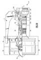
- FIG. 4Ais an aft perspective view of an aft mount
- FIG. 4Bis an aft view of an aft mount of FIG. 4A ;
- FIG. 4Cis a front view of the aft mount of FIG. 4A ;
- FIG. 4Dis a side view of the aft mount of FIG. 4A ;
- FIG. 4Eis a top view of the aft mount of FIG. 4A ;
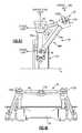
- FIG. 5Ais a side view of the aft mount of FIG. 4A in a first slide position
- FIG. 5Bis a side view of the aft mount of FIG. 4A in a second slide position.
- FIG. 1Aillustrates a general partial fragmentary schematic view of a gas turbofan engine 10 suspended from an engine pylon 12 within an engine nacelle assembly N as is typical of an aircraft designed for subsonic operation.
- the turbofan engine 10includes a core engine within a core nacelle C that houses a low spool 14 and high spool 24 .
- the low spool 14includes a low pressure compressor 16 and low pressure turbine 18 .
- the low spool 14drives a fan section 20 connected to the low spool 14 either directly or through a gear train 25 .
- the high spool 24includes a high pressure compressor 26 and high pressure turbine 28 .
- a combustor 30is arranged between the high pressure compressor 26 and high pressure turbine 28 .
- the low and high spools 14 , 24rotate about an engine axis of rotation A.
- the engine 10 in one non-limiting embodimentis a high-bypass geared architecture aircraft engine.
- the engine 10 bypass ratiois greater than ten (10:1)
- the turbofan diameteris significantly larger than that of the low pressure compressor 16
- the low pressure turbine 18has a pressure ratio that is greater than 5:1.
- the gear train 25may be an epicycle gear train such as a planetary gear system or other gear system with a gear reduction ratio of greater than 2.5:1. It should be understood, however, that the above parameters are only exemplary of one embodiment of a geared architecture engine and that the present invention is applicable to other gas turbine engines including direct drive turbofans.
- the fan section 20communicates airflow into the core nacelle C to the low pressure compressor 16 .
- Core airflow compressed by the low pressure compressor 16 and the high pressure compressor 26is mixed with the fuel in the combustor 30 where is ignited, and burned.
- the resultant high pressure combustor productsare expanded through the high pressure turbine 28 and low pressure turbine 18 .
- the turbines 28 , 18are rotationally coupled to the compressors 26 , 16 respectively to drive the compressors 26 , 16 in response to the expansion of the combustor product.
- the low pressure turbine 18also drives the fan section 20 through gear train 25 .
- a core engine exhaust Eexits the core nacelle C through a core nozzle 43 defined between the core nacelle C and a tail cone 33 .
- the engine static structure 44generally has sub-structures including a case structure often referred to as the engine backbone.
- the engine static structure 44generally includes a fan case 46 , an intermediate case (IMC) 48 , a high pressure compressor case 50 , a combustor case 52 A, a high pressure turbine case 52 B, a thrust case 52 C, a low pressure turbine case 54 , and a turbine exhaust case 56 ( FIG. 1B ).
- the combustor case 52 A, the high pressure turbine case 52 B and the thrust case 52 Cmay be combined into a single case. It should be understood that this is an exemplary configuration and any number of cases may be utilized.
- the fan section 20includes a fan rotor 32 with a plurality of circumferentially spaced radially outwardly extending fan blades 34 .
- the fan blades 34are surrounded by the fan case 46 .
- the core engine case structureis secured to the fan case 46 at the IMC 48 which includes a multiple of circumferentially spaced radially extending struts 40 which radially span the core engine case structure and the fan case 20 .
- the engine static structure 44further supports a bearing system upon which the turbines 28 , 18 , compressors 26 , 16 and fan rotor 32 rotate.
- a #1 fan dual bearing 60which rotationally supports the fan rotor 32 is axially located generally within the fan case 46 .
- the #1 fan dual bearing 60is preloaded to react fan thrust forward and aft (in case of surge).
- a #2 LPC bearing 62which rotationally supports the low spool 14 is axially located generally within the intermediate case (IMC) 48 .
- the #2 LPC bearing 62reacts thrust.
- a #3 fan dual bearing 64which rotationally supports the high spool 24 and also reacts thrust.
- the #3 fan bearing 64is also axially located generally within the IMC 48 just forward of the high pressure compressor case 50 .
- a #4 bearing 66which rotationally supports a rear segment of the low spool 14 reacts only radial loads.
- the #4 bearing 66is axially located generally within the thrust case 52 C in an aft section thereof.
- a #5 bearing 68rotationally supports the rear segment of the low spool 14 and reacts only radial loads.
- the #5 bearing 68is axially located generally within the thrust case 52 C just aft of the #4 bearing 66 . It should be understood that this is an exemplary configuration and any number of bearings may be utilized.
- the #4 bearing 66 and the #5 bearing 68are supported within a mid-turbine frame (MTF) 70 to straddle radially extending structural struts 72 which are preloaded in tension ( FIGS. 1C-1D ).
- the MTF 70provides aft structural support within the thrust case 52 C for the #4 bearing 66 and the #5 bearing 68 which rotatably support the spools 14 , 24 .
- a dual rotor engine such as that disclosed in the illustrated embodimenttypically includes a forward frame and a rear frame that support the main rotor bearings.
- the intermediate case (IMC) 48also includes the radially extending struts 40 which are generally radially aligned with the #2 LPC bearing 62 ( FIG. 1B ). It should be understood that various engines with various case and frame structures will benefit from the present invention.
- the turbofan gas turbine engine 10is mounted to aircraft structure such as an aircraft wing through a mount system 80 attachable by the pylon 12 .
- the mount system 80includes a forward mount 82 and an aft mount 84 ( FIG. 2A ).
- the forward mount 82is secured to the IMC 48 and the aft mount 84 is secured to the MTF 70 at the thrust case 52 C.
- the forward mount 82 and the aft mount 84are arranged in a plane containing the axis A of the turbofan gas turbine 10 . This eliminates the thrust links from the intermediate case, which frees up valuable space beneath the core nacelle and minimizes IMC 48 distortion.
- the mount system 80reacts the engine thrust at the aft end of the engine 10 .
- the term “reacts” as utilized in this disclosureis defined as absorbing a load and dissipating the load to another location of the gas turbine engine 10 .
- the forward mount 82supports vertical loads and side loads.
- the forward mount 82in one non-limiting embodiment includes a shackle arrangement which mounts to the IMC 48 at two points 86 A, 86 B.
- the forward mount 82is generally a plate-like member which is oriented transverse to the plane which contains engine axis A. Fasteners are oriented through the forward mount 82 to engage the intermediate case (IMC) 48 generally parallel to the engine axis A.
- the forward mount 82is secured to the IMC 40 .
- the forward mount 82is secured to a portion of the core engine, such as the high-pressure compressor case 50 of the gas turbine engine 10 (see FIG. 3 ).
- the forward mount 82is secured to a portion of the core engine, such as the high-pressure compressor case 50 of the gas turbine engine 10 (see FIG. 3 ).
- the aft mount 84generally includes a first A-arm 88 A, a second A-arm 88 B, a rear mount platform 90 , a wiffle tree assembly 92 and a drag link 94 .
- the rear mount platform 90is attached directly to aircraft structure such as the pylon 12 .
- the first A-arm 88 A and the second A-arm 88 Bmount between the thrust case 52 C at case bosses 96 which interact with the MTF 70 ( FIGS. 4B-4C ), the rear mount platform 90 and the wiffle tree assembly 92 .
- the first A-arm 88 A and the second A-arm 88 Bmay alternatively mount to other areas of the engine 10 such as the high pressure turbine case or other cases.
- other frame arrangementsmay alternatively be used with any engine case arrangement.
- the first A-arm 88 A and the second A-arm 88 Bare rigid generally triangular arrangements, each having a first link arm 89 a , a second link arm 89 b and a third link arm 89 c .
- the first link arm 89 ais between the case boss 96 and the rear mount platform 90 .
- the second link arm 89 bis between the case bosses 96 and the wiffle tree assembly 92 .
- the third link arm 89 cis between the wiffle tree assembly 92 rear mount platform 90 .
- the first A-arm 88 A and the second A-arm 88 Bprimarily support the vertical weight load of the engine 10 and transmit thrust loads from the engine to the rear mount platform 90 .
- the first A-arm 88 A and the second A-arm 88 B of the aft mount 84force the resultant thrust vector at the engine casing to be reacted along the engine axis A which minimizes tip clearance losses due to engine loading at the aft mount 84 . This minimizes blade tip clearance requirements and thereby improves engine performance.
- the wiffle tree assembly 92includes a wiffle link 98 which supports a central ball joint 100 , a first sliding ball joint 102 A and a second sliding ball joint 102 B ( FIG. 4E ). It should be understood that various bushings, vibration isolators and such like may additionally be utilized herewith.
- the central ball joint 100is attached directly to aircraft structure such as the pylon 12 .
- the first sliding ball joint 102 Ais attached to the first A-arm 88 A and the second sliding ball joint 102 B is mounted to the first A-arm 88 A.
- the first and second sliding ball joint 102 A, 102 Bpermit sliding movement of the first and second A-arm 88 A, 88 B (illustrated by arrow S in FIGS.
- the wiffle tree assembly 92allows all engine thrust loads to be equalized transmitted to the engine pylon 12 through the rear mount platform 90 by the sliding movement and equalize the thrust load that results from the dual thrust link configuration.
- the wiffle link 98operates as an equalizing link for vertical loads due to the first sliding ball joint 102 A and the second sliding ball joint 102 B. As the wiffle link 98 rotates about the central ball joint 100 thrust forces are equalized in the axial direction.
- the wiffle tree assembly 92experiences loading only due to vertical loads, and is thus less susceptible to failure than conventional thrust-loaded designs.
- the drag link 94includes a ball joint 104 A mounted to the thrust case 52 C and ball joint 104 B mounted to the rear mount platform 90 ( FIGS. 4B-4C ).
- the drag link 94operates to react torque.
- the aft mount 84transmits engine loads directly to the thrust case 52 C and the MTF 70 . Thrust, vertical, side, and torque loads are transmitted directly from the MTF 70 which reduces the number of structural members as compared to current in-practice designs.
- the mount system 80is compact, and occupies space within the core nacelle volume as compared to turbine exhaust case-mounted configurations, which occupy space outside of the core nacelle which may require additional or relatively larger aerodynamic fairings and increase aerodynamic drag and fuel consumption.
- the mount system 80eliminates the heretofore required thrust links from the IMC, which frees up valuable space adjacent the IMC 48 and the high pressure compressor case 50 within the core nacelle C.
Landscapes
- Engineering & Computer Science (AREA)
- Aviation & Aerospace Engineering (AREA)
- Turbine Rotor Nozzle Sealing (AREA)
- Structures Of Non-Positive Displacement Pumps (AREA)
- Retarders (AREA)
Abstract
Description
Claims (18)
Priority Applications (22)
| Application Number | Priority Date | Filing Date | Title |
|---|---|---|---|
| US12/131,876US8128021B2 (en) | 2008-06-02 | 2008-06-02 | Engine mount system for a turbofan gas turbine engine |
| US13/336,140US8267349B2 (en) | 2008-06-02 | 2011-12-23 | Engine mount system for a turbofan gas turbine engine |
| US13/340,834US8695920B2 (en) | 2008-06-02 | 2011-12-30 | Gas turbine engine with low stage count low pressure turbine |
| US13/340,988US8800914B2 (en) | 2008-06-02 | 2011-12-30 | Gas turbine engine with low stage count low pressure turbine |
| US13/340,940US8684303B2 (en) | 2008-06-02 | 2011-12-30 | Gas turbine engine compressor arrangement |
| US13/340,969US8807477B2 (en) | 2008-06-02 | 2011-12-30 | Gas turbine engine compressor arrangement |
| US13/485,126US8511605B2 (en) | 2008-06-02 | 2012-05-31 | Gas turbine engine with low stage count low pressure turbine |
| US13/484,361US8448895B2 (en) | 2008-06-02 | 2012-05-31 | Gas turbine engine compressor arrangement |
| US13/484,400US8511604B2 (en) | 2008-06-02 | 2012-05-31 | Gas turbine engine with low stage count low pressure turbine |
| US14/190,429US20140174056A1 (en) | 2008-06-02 | 2014-02-26 | Gas turbine engine with low stage count low pressure turbine |
| US14/755,221US20150300207A1 (en) | 2008-06-02 | 2015-06-30 | Gas turbine engine with low stage count low pressure turbine |
| US14/755,366US20150315977A1 (en) | 2008-06-02 | 2015-06-30 | Gas turbine engine with low stage count low pressure turbine |
| US14/796,209US20160032828A1 (en) | 2008-06-02 | 2015-07-10 | Gas turbine engine with low stage count low pressure turbine |
| US14/801,925US20160047268A1 (en) | 2008-06-02 | 2015-07-17 | Gas turbine engine with low stage count low pressure turbine |
| US14/872,405US20160024957A1 (en) | 2008-06-02 | 2015-10-01 | Gas turbine engine with low stage count low pressure turbine |
| US14/872,508US20160024958A1 (en) | 2008-06-02 | 2015-10-01 | Gas turbine engine with low stage count low pressure turbine |
| US14/966,538US20160097304A1 (en) | 2008-06-02 | 2015-12-11 | Gas turbine engine with low stage count low pressure turbine |
| US15/173,288US10451004B2 (en) | 2008-06-02 | 2016-06-03 | Gas turbine engine with low stage count low pressure turbine |
| US16/405,149US11286883B2 (en) | 2008-06-02 | 2019-05-07 | Gas turbine engine with low stage count low pressure turbine and engine mounting arrangement |
| US17/395,553US11731773B2 (en) | 2008-06-02 | 2021-08-06 | Engine mount system for a gas turbine engine |
| US18/215,394US12179929B2 (en) | 2008-06-02 | 2023-06-28 | Engine mount system for a gas turbine engine |
| US18/937,193US12421916B2 (en) | 2008-06-02 | 2024-11-05 | Engine mount system for a gas turbine engine |
Applications Claiming Priority (1)
| Application Number | Priority Date | Filing Date | Title |
|---|---|---|---|
| US12/131,876US8128021B2 (en) | 2008-06-02 | 2008-06-02 | Engine mount system for a turbofan gas turbine engine |
Related Child Applications (5)
| Application Number | Title | Priority Date | Filing Date |
|---|---|---|---|
| US13/336,140ContinuationUS8267349B2 (en) | 2008-06-02 | 2011-12-23 | Engine mount system for a turbofan gas turbine engine |
| US13/340,988Continuation-In-PartUS8800914B2 (en) | 2008-06-02 | 2011-12-30 | Gas turbine engine with low stage count low pressure turbine |
| US13/340,940ContinuationUS8684303B2 (en) | 2008-06-02 | 2011-12-30 | Gas turbine engine compressor arrangement |
| US13/340,834Continuation-In-PartUS8695920B2 (en) | 2008-06-02 | 2011-12-30 | Gas turbine engine with low stage count low pressure turbine |
| US13/340,969Continuation-In-PartUS8807477B2 (en) | 2008-06-02 | 2011-12-30 | Gas turbine engine compressor arrangement |
Publications (2)
| Publication Number | Publication Date |
|---|---|
| US20090314881A1 US20090314881A1 (en) | 2009-12-24 |
| US8128021B2true US8128021B2 (en) | 2012-03-06 |
Family
ID=41430218
Family Applications (3)
| Application Number | Title | Priority Date | Filing Date |
|---|---|---|---|
| US12/131,876Active2031-09-29US8128021B2 (en) | 2008-06-02 | 2008-06-02 | Engine mount system for a turbofan gas turbine engine |
| US13/336,140ActiveUS8267349B2 (en) | 2008-06-02 | 2011-12-23 | Engine mount system for a turbofan gas turbine engine |
| US13/340,940Active2028-07-11US8684303B2 (en) | 2008-06-02 | 2011-12-30 | Gas turbine engine compressor arrangement |
Family Applications After (2)
| Application Number | Title | Priority Date | Filing Date |
|---|---|---|---|
| US13/336,140ActiveUS8267349B2 (en) | 2008-06-02 | 2011-12-23 | Engine mount system for a turbofan gas turbine engine |
| US13/340,940Active2028-07-11US8684303B2 (en) | 2008-06-02 | 2011-12-30 | Gas turbine engine compressor arrangement |
Country Status (1)
| Country | Link |
|---|---|
| US (3) | US8128021B2 (en) |
Cited By (17)
| Publication number | Priority date | Publication date | Assignee | Title |
|---|---|---|---|---|
| US8567745B2 (en)* | 2011-12-15 | 2013-10-29 | United Technologies Corporation | Apparatuses and systems with vertically and longitudinally offset mounting flanges |
| US20140033734A1 (en)* | 2012-08-06 | 2014-02-06 | Eugene Lockhart | Stator anti-rotation lug |
| WO2014036554A1 (en) | 2012-08-31 | 2014-03-06 | United Technologies Corporation | Assembly for mounting a turbine engine to a pylon |
| US8801376B2 (en) | 2011-09-02 | 2014-08-12 | Pratt & Whitney Canada Corp. | Fabricated intermediate case with engine mounts |
| US20150192298A1 (en)* | 2007-07-27 | 2015-07-09 | United Technologies Corporation | Gas turbine engine with improved fuel efficiency |
| US20150239568A1 (en)* | 2012-10-02 | 2015-08-27 | United Technologies Corporation | Pylon shape with geared turbofan for structural stiffness |
| US9211955B1 (en)* | 2012-12-10 | 2015-12-15 | The Boeing Company | Methods and apparatus for supporting engines and nacelles relative to aircraft wings |
| US9217337B2 (en) | 2012-05-10 | 2015-12-22 | United Technologies Corporation | Adjustable engine mount |
| US20160362983A1 (en)* | 2012-01-31 | 2016-12-15 | United Technologies Corporation | Low noise turbine for geared turbofan engine |
| US9551238B2 (en) | 2012-09-28 | 2017-01-24 | United Technologies Corporation | Pin connector for ceramic matrix composite turbine frame |
| US20170343574A1 (en)* | 2012-09-28 | 2017-11-30 | United Technologies Corporation | Low noise compressor and turbine for geared turbofan engine |
| US9915225B2 (en)* | 2015-02-06 | 2018-03-13 | United Technologies Corporation | Propulsion system arrangement for turbofan gas turbine engine |
| US10144524B2 (en) | 2013-06-14 | 2018-12-04 | Rohr, Inc. | Assembly for mounting a turbine engine to a pylon |
| US10451004B2 (en) | 2008-06-02 | 2019-10-22 | United Technologies Corporation | Gas turbine engine with low stage count low pressure turbine |
| US11781506B2 (en) | 2020-06-03 | 2023-10-10 | Rtx Corporation | Splitter and guide vane arrangement for gas turbine engines |
| US12129767B1 (en) | 2023-06-12 | 2024-10-29 | General Electric Company | Gas turbine mounting configurations for bending mitigation |
| US20250242932A1 (en)* | 2024-01-29 | 2025-07-31 | Airbus Operations Sas | Forward engine mount for a half or full wraparound pylon |
Families Citing this family (129)
| Publication number | Priority date | Publication date | Assignee | Title |
|---|---|---|---|---|
| US8667688B2 (en) | 2006-07-05 | 2014-03-11 | United Technologies Corporation | Method of assembly for gas turbine fan drive gear system |
| US7704178B2 (en) | 2006-07-05 | 2010-04-27 | United Technologies Corporation | Oil baffle for gas turbine fan drive gear system |
| US8858388B2 (en) | 2006-08-15 | 2014-10-14 | United Technologies Corporation | Gas turbine engine gear train |
| US8753243B2 (en) | 2006-08-15 | 2014-06-17 | United Technologies Corporation | Ring gear mounting arrangement with oil scavenge scheme |
| US10107231B2 (en) | 2006-08-15 | 2018-10-23 | United Technologies Corporation | Gas turbine engine with geared architecture |
| US9976437B2 (en) | 2006-08-15 | 2018-05-22 | United Technologies Corporation | Epicyclic gear train |
| US8104262B2 (en) | 2006-10-12 | 2012-01-31 | United Technologies Corporation | Dual function cascade integrated variable area fan nozzle and thrust reverser |
| US20080273961A1 (en) | 2007-03-05 | 2008-11-06 | Rosenkrans William E | Flutter sensing and control system for a gas turbine engine |
| US11346289B2 (en) | 2007-08-01 | 2022-05-31 | Raytheon Technologies Corporation | Turbine section of high bypass turbofan |
| US11486311B2 (en) | 2007-08-01 | 2022-11-01 | Raytheon Technologies Corporation | Turbine section of high bypass turbofan |
| US20150377123A1 (en) | 2007-08-01 | 2015-12-31 | United Technologies Corporation | Turbine section of high bypass turbofan |
| US11149650B2 (en) | 2007-08-01 | 2021-10-19 | Raytheon Technologies Corporation | Turbine section of high bypass turbofan |
| US11242805B2 (en) | 2007-08-01 | 2022-02-08 | Raytheon Technologies Corporation | Turbine section of high bypass turbofan |
| US8844265B2 (en)* | 2007-08-01 | 2014-09-30 | United Technologies Corporation | Turbine section of high bypass turbofan |
| US9701415B2 (en) | 2007-08-23 | 2017-07-11 | United Technologies Corporation | Gas turbine engine with axial movable fan variable area nozzle |
| US9957918B2 (en) | 2007-08-28 | 2018-05-01 | United Technologies Corporation | Gas turbine engine front architecture |
| US20140157754A1 (en) | 2007-09-21 | 2014-06-12 | United Technologies Corporation | Gas turbine engine compressor arrangement |
| FR2924684B1 (en)* | 2007-12-07 | 2010-01-01 | Snecma | SUSPENSION OF A TURBOJET ENGINE TO AN AIRCRAFT |
| US8128021B2 (en) | 2008-06-02 | 2012-03-06 | United Technologies Corporation | Engine mount system for a turbofan gas turbine engine |
| US8695920B2 (en)* | 2008-06-02 | 2014-04-15 | United Technologies Corporation | Gas turbine engine with low stage count low pressure turbine |
| US8807477B2 (en) | 2008-06-02 | 2014-08-19 | United Technologies Corporation | Gas turbine engine compressor arrangement |
| US8511605B2 (en) | 2008-06-02 | 2013-08-20 | United Technologies Corporation | Gas turbine engine with low stage count low pressure turbine |
| US8800914B2 (en) | 2008-06-02 | 2014-08-12 | United Technologies Corporation | Gas turbine engine with low stage count low pressure turbine |
| US9885313B2 (en) | 2009-03-17 | 2018-02-06 | United Technologes Corporation | Gas turbine engine bifurcation located fan variable area nozzle |
| JP5642379B2 (en)* | 2009-12-01 | 2014-12-17 | 三菱航空機株式会社 | Aircraft engine mount, aircraft |
| US9995174B2 (en) | 2010-10-12 | 2018-06-12 | United Technologies Corporation | Planetary gear system arrangement with auxiliary oil system |
| US10605167B2 (en) | 2011-04-15 | 2020-03-31 | United Technologies Corporation | Gas turbine engine front center body architecture |
| US8777793B2 (en) | 2011-04-27 | 2014-07-15 | United Technologies Corporation | Fan drive planetary gear system integrated carrier and torque frame |
| US9239012B2 (en) | 2011-06-08 | 2016-01-19 | United Technologies Corporation | Flexible support structure for a geared architecture gas turbine engine |
| US9631558B2 (en) | 2012-01-03 | 2017-04-25 | United Technologies Corporation | Geared architecture for high speed and small volume fan drive turbine |
| US9523422B2 (en) | 2011-06-08 | 2016-12-20 | United Technologies Corporation | Flexible support structure for a geared architecture gas turbine engine |
| GB2492107B (en)* | 2011-06-22 | 2013-09-04 | Rolls Royce Plc | Mounting assembly |
| US9506422B2 (en) | 2011-07-05 | 2016-11-29 | United Technologies Corporation | Efficient, low pressure ratio propulsor for gas turbine engines |
| US9909505B2 (en) | 2011-07-05 | 2018-03-06 | United Technologies Corporation | Efficient, low pressure ratio propulsor for gas turbine engines |
| US9828105B2 (en) | 2011-08-24 | 2017-11-28 | United Technologies Corporation | Nacelle assembly having integrated afterbody mount case |
| US20130074517A1 (en) | 2011-09-23 | 2013-03-28 | United Technologies Corporation | Gas turbine engine mount assembly |
| US9840917B2 (en) | 2011-12-13 | 2017-12-12 | United Technologies Corporation | Stator vane shroud having an offset |
| US12331691B2 (en) | 2011-12-27 | 2025-06-17 | Rtx Corporation | Gas turbine engine compressor arrangement |
| BR102012028940A2 (en)* | 2011-12-30 | 2015-10-06 | United Technologies Corp | gas turbine engine |
| EP3088702A1 (en)* | 2011-12-30 | 2016-11-02 | United Technologies Corporation | Gas turbine engine gear train |
| US9416677B2 (en) | 2012-01-10 | 2016-08-16 | United Technologies Corporation | Gas turbine engine forward bearing compartment architecture |
| US20130186058A1 (en) | 2012-01-24 | 2013-07-25 | William G. Sheridan | Geared turbomachine fan and compressor rotation |
| US10400629B2 (en) | 2012-01-31 | 2019-09-03 | United Technologies Corporation | Gas turbine engine shaft bearing configuration |
| US20130192198A1 (en) | 2012-01-31 | 2013-08-01 | Lisa I. Brilliant | Compressor flowpath |
| US20130192251A1 (en) | 2012-01-31 | 2013-08-01 | Peter M. Munsell | Buffer system that communicates buffer supply air to one or more portions of a gas turbine engine |
| US8863491B2 (en) | 2012-01-31 | 2014-10-21 | United Technologies Corporation | Gas turbine engine shaft bearing configuration |
| US9038366B2 (en) | 2012-01-31 | 2015-05-26 | United Technologies Corporation | LPC flowpath shape with gas turbine engine shaft bearing configuration |
| US9394852B2 (en) | 2012-01-31 | 2016-07-19 | United Technologies Corporation | Variable area fan nozzle with wall thickness distribution |
| US10415468B2 (en) | 2012-01-31 | 2019-09-17 | United Technologies Corporation | Gas turbine engine buffer system |
| US8869508B2 (en) | 2012-01-31 | 2014-10-28 | United Technologies Corporation | Gas turbine engine variable area fan nozzle control |
| US10113434B2 (en) | 2012-01-31 | 2018-10-30 | United Technologies Corporation | Turbine blade damper seal |
| US20150204238A1 (en)* | 2012-01-31 | 2015-07-23 | United Technologies Corporation | Low noise turbine for geared turbofan engine |
| US10287914B2 (en) | 2012-01-31 | 2019-05-14 | United Technologies Corporation | Gas turbine engine with high speed low pressure turbine section and bearing support features |
| US20130192191A1 (en) | 2012-01-31 | 2013-08-01 | Frederick M. Schwarz | Gas turbine engine with high speed low pressure turbine section and bearing support features |
| US10724431B2 (en) | 2012-01-31 | 2020-07-28 | Raytheon Technologies Corporation | Buffer system that communicates buffer supply air to one or more portions of a gas turbine engine |
| US9169781B2 (en) | 2012-01-31 | 2015-10-27 | United Technologies Corporation | Turbine engine gearbox |
| US10107191B2 (en) | 2012-02-29 | 2018-10-23 | United Technologies Corporation | Geared gas turbine engine with reduced fan noise |
| US20130233997A1 (en)* | 2012-03-12 | 2013-09-12 | United Technologies Corporation | Turbine engine case mount |
| US20130232768A1 (en)* | 2012-03-12 | 2013-09-12 | United Technologies Corporation | Turbine engine case mount and dismount |
| US8790075B2 (en)* | 2012-03-30 | 2014-07-29 | United Technologies Corporation | Gas turbine engine geared architecture axial retention arrangement |
| US10125693B2 (en) | 2012-04-02 | 2018-11-13 | United Technologies Corporation | Geared turbofan engine with power density range |
| US10138809B2 (en) | 2012-04-02 | 2018-11-27 | United Technologies Corporation | Geared turbofan engine with a high ratio of thrust to turbine volume |
| US9194296B2 (en) | 2012-05-18 | 2015-11-24 | Pratt & Whitney Canada Corp. | Inner bypass duct wall attachment |
| US8572943B1 (en) | 2012-05-31 | 2013-11-05 | United Technologies Corporation | Fundamental gear system architecture |
| US20150308351A1 (en)* | 2012-05-31 | 2015-10-29 | United Technologies Corporation | Fundamental gear system architecture |
| US8756908B2 (en) | 2012-05-31 | 2014-06-24 | United Technologies Corporation | Fundamental gear system architecture |
| US20130318998A1 (en)* | 2012-05-31 | 2013-12-05 | Frederick M. Schwarz | Geared turbofan with three turbines with high speed fan drive turbine |
| US8950724B2 (en) | 2012-06-28 | 2015-02-10 | Solar Turbines Inc. | Turbine engine mounting system and method |
| WO2014052967A1 (en)* | 2012-09-28 | 2014-04-03 | United Technologies Corporation | Case assembly for a gas turbine engine |
| WO2014051672A1 (en) | 2012-09-28 | 2014-04-03 | United Technologies Corporation | Split-zone flow metering t-tube |
| JP6078160B2 (en) | 2012-09-28 | 2017-02-08 | ユナイテッド テクノロジーズ コーポレイションUnited Technologies Corporation | Assembly method of gas turbine fan drive gear system |
| BR112015007733B1 (en) | 2012-10-08 | 2022-05-03 | United Technologies Corporation | Gas turbine engines, and, method for distributing weight between a propeller assembly and a gas generator assembly of a gas turbine engine |
| WO2014058710A1 (en) | 2012-10-09 | 2014-04-17 | United Technologies Corporation | Improved operability geared turbofan engine including compressor section variable guide vanes |
| US9932933B2 (en) | 2012-12-20 | 2018-04-03 | United Technologies Corporation | Low pressure ratio fan engine having a dimensional relationship between inlet and fan size |
| US9920653B2 (en) | 2012-12-20 | 2018-03-20 | United Technologies Corporation | Low pressure ratio fan engine having a dimensional relationship between inlet and fan size |
| US10436120B2 (en) | 2013-02-06 | 2019-10-08 | United Technologies Corporation | Exhaust nozzle for an elongated gear turbofan with high bypass ratio |
| WO2014133778A1 (en)* | 2013-02-26 | 2014-09-04 | United Technologies Corporation | Assembly with blind installation capability |
| US9394829B2 (en) | 2013-03-05 | 2016-07-19 | Solar Turbines Incorporated | System and method for aligning a gas turbine engine |
| US8641366B1 (en) | 2013-03-07 | 2014-02-04 | United Technologies Corporation | Non-contacting seals for geared gas turbine engine bearing compartments |
| US9863326B2 (en) | 2013-03-12 | 2018-01-09 | United Technologies Corporation | Flexible coupling for geared turbine engine |
| EP2969758B1 (en)* | 2013-03-13 | 2018-01-03 | United Technologies Corporation | Engine mounting system |
| US20150013301A1 (en)* | 2013-03-13 | 2015-01-15 | United Technologies Corporation | Turbine engine including balanced low pressure stage count |
| US11719161B2 (en) | 2013-03-14 | 2023-08-08 | Raytheon Technologies Corporation | Low noise turbine for geared gas turbine engine |
| US10605172B2 (en) | 2013-03-14 | 2020-03-31 | United Technologies Corporation | Low noise turbine for geared gas turbine engine |
| US10724479B2 (en) | 2013-03-15 | 2020-07-28 | United Technologies Corporation | Thrust efficient turbofan engine |
| US9885282B2 (en) | 2013-03-15 | 2018-02-06 | United Technologies Corporation | Turbofan engine bearing and gearbox arrangement |
| WO2015012923A2 (en) | 2013-05-09 | 2015-01-29 | United Technologies Corporation | Turbofan engine front section |
| EP3957847A1 (en) | 2013-05-09 | 2022-02-23 | Raytheon Technologies Corporation | Turbofan engine front section |
| EP3058202A4 (en) | 2013-10-16 | 2017-06-28 | United Technologies Corporation | Geared turbofan engine with targeted modular efficiency |
| EP3063385A4 (en) | 2013-11-01 | 2017-07-12 | United Technologies Corporation | Geared turbofan arrangement with core split power ratio |
| US10502163B2 (en) | 2013-11-01 | 2019-12-10 | United Technologies Corporation | Geared turbofan arrangement with core split power ratio |
| US8869504B1 (en) | 2013-11-22 | 2014-10-28 | United Technologies Corporation | Geared turbofan engine gearbox arrangement |
| US10570916B2 (en) | 2014-02-19 | 2020-02-25 | United Technologies Corporation | Gas turbine engine airfoil |
| US10605259B2 (en) | 2014-02-19 | 2020-03-31 | United Technologies Corporation | Gas turbine engine airfoil |
| WO2015126715A1 (en) | 2014-02-19 | 2015-08-27 | United Technologies Corporation | Gas turbine engine airfoil |
| EP3108121B1 (en) | 2014-02-19 | 2023-09-06 | Raytheon Technologies Corporation | Turbofan engine with geared architecture and lpc airfoils |
| WO2015175043A2 (en) | 2014-02-19 | 2015-11-19 | United Technologies Corporation | Gas turbine engine airfoil |
| WO2015175056A2 (en) | 2014-02-19 | 2015-11-19 | United Technologies Corporation | Gas turbine engine airfoil |
| EP3108113A4 (en) | 2014-02-19 | 2017-03-15 | United Technologies Corporation | Gas turbine engine airfoil |
| US10557477B2 (en) | 2014-02-19 | 2020-02-11 | United Technologies Corporation | Gas turbine engine airfoil |
| US10280843B2 (en) | 2014-03-07 | 2019-05-07 | United Technologies Corporation | Geared turbofan with integral front support and carrier |
| US9869190B2 (en) | 2014-05-30 | 2018-01-16 | General Electric Company | Variable-pitch rotor with remote counterweights |
| US9976490B2 (en) | 2014-07-01 | 2018-05-22 | United Technologies Corporation | Geared gas turbine engine with oil deaerator |
| US10060289B2 (en) | 2014-07-29 | 2018-08-28 | United Technologies Corporation | Geared gas turbine engine with oil deaerator and air removal |
| US10072510B2 (en) | 2014-11-21 | 2018-09-11 | General Electric Company | Variable pitch fan for gas turbine engine and method of assembling the same |
| US10125722B2 (en) | 2015-02-13 | 2018-11-13 | United Technologies Corporation | Turbine engine with a turbo-compressor |
| US10337401B2 (en) | 2015-02-13 | 2019-07-02 | United Technologies Corporation | Turbine engine with a turbo-compressor |
| US10041408B2 (en)* | 2015-02-13 | 2018-08-07 | United Technologies Corporation | Turbine engine with a turbo-compressor |
| US9470093B2 (en) | 2015-03-18 | 2016-10-18 | United Technologies Corporation | Turbofan arrangement with blade channel variations |
| US10371168B2 (en) | 2015-04-07 | 2019-08-06 | United Technologies Corporation | Modal noise reduction for gas turbine engine |
| US10458270B2 (en) | 2015-06-23 | 2019-10-29 | United Technologies Corporation | Roller bearings for high ratio geared turbofan engine |
| US10100653B2 (en) | 2015-10-08 | 2018-10-16 | General Electric Company | Variable pitch fan blade retention system |
| US10508562B2 (en) | 2015-12-01 | 2019-12-17 | United Technologies Corporation | Geared turbofan with four star/planetary gear reduction |
| US10669948B2 (en) | 2017-01-03 | 2020-06-02 | Raytheon Technologies Corporation | Geared turbofan with non-epicyclic gear reduction system |
| US10436072B2 (en) | 2017-02-17 | 2019-10-08 | General Electric Company | Elastomeric shock absorbers for gas turbine transportation |
| US10738646B2 (en) | 2017-06-12 | 2020-08-11 | Raytheon Technologies Corporation | Geared turbine engine with gear driving low pressure compressor and fan at common speed, and failsafe overspeed protection and shear section |
| US10724445B2 (en) | 2018-01-03 | 2020-07-28 | Raytheon Technologies Corporation | Method of assembly for fan drive gear system with rotating carrier |
| US11092020B2 (en) | 2018-10-18 | 2021-08-17 | Raytheon Technologies Corporation | Rotor assembly for gas turbine engines |
| FR3094412A1 (en)* | 2019-03-25 | 2020-10-02 | Airbus Operations | DOUBLE-FLOW TURBOREACTOR CONTAINING A SERIES OF ROTATING BLADES TO CLOSE THE SECONDARY FLOW VEIN |
| US11420755B2 (en)* | 2019-08-08 | 2022-08-23 | General Electric Company | Shape memory alloy isolator for a gas turbine engine |
| CN112849418B (en)* | 2019-11-27 | 2022-12-16 | 中国航发商用航空发动机有限责任公司 | Aircraft engine mounting system and aircraft |
| US11674435B2 (en) | 2021-06-29 | 2023-06-13 | General Electric Company | Levered counterweight feathering system |
| US11795964B2 (en) | 2021-07-16 | 2023-10-24 | General Electric Company | Levered counterweight feathering system |
| US11719245B2 (en) | 2021-07-19 | 2023-08-08 | Raytheon Technologies Corporation | Compressor arrangement for a gas turbine engine |
| US12392280B2 (en) | 2021-07-19 | 2025-08-19 | Rtx Corporation | Gas turbine engine with high low spool power extraction ratio |
| US11754000B2 (en) | 2021-07-19 | 2023-09-12 | Rtx Corporation | High and low spool configuration for a gas turbine engine |
| US11814968B2 (en) | 2021-07-19 | 2023-11-14 | Rtx Corporation | Gas turbine engine with idle thrust ratio |
| US12123356B2 (en) | 2021-07-19 | 2024-10-22 | Rtx Corporation | Gas turbine engine with higher low spool torque-to-thrust ratio |
| CN117171918B (en)* | 2023-09-11 | 2025-01-10 | 天津大学 | Variable nozzle turbine design method under geometric and pneumatic constraints |
Citations (43)
| Publication number | Priority date | Publication date | Assignee | Title |
|---|---|---|---|---|
| US4966338A (en) | 1987-08-05 | 1990-10-30 | General Electric Company | Aircraft pylon |
| US5136839A (en) | 1988-09-28 | 1992-08-11 | Short Brothers Plc | Ducted fan turbine engine |
| US5174525A (en) | 1991-09-26 | 1992-12-29 | General Electric Company | Structure for eliminating lift load bending in engine core of turbofan |
| US5273393A (en) | 1992-03-26 | 1993-12-28 | Rolls-Royce Plc | Gas turbine engine casing |
| US5275357A (en)* | 1992-01-16 | 1994-01-04 | General Electric Company | Aircraft engine mount |
| US5277382A (en)* | 1992-10-13 | 1994-01-11 | General Electric Company | Aircraft engine forward mount |
| US5320307A (en)* | 1992-03-25 | 1994-06-14 | General Electric Company | Aircraft engine thrust mount |
| US5372338A (en) | 1992-04-15 | 1994-12-13 | Rolls-Royce Plc | Mounting arrangement for a gas turbine engine |
| US5409184A (en) | 1993-02-20 | 1995-04-25 | Rolls-Royce Plc | Mounting for coupling a turbofan gas turbine engine to an aircraft structure |
| US5443229A (en) | 1993-12-13 | 1995-08-22 | General Electric Company | Aircraft gas turbine engine sideways mount |
| US5452575A (en) | 1993-09-07 | 1995-09-26 | General Electric Company | Aircraft gas turbine engine thrust mount |
| US5474258A (en) | 1991-11-25 | 1995-12-12 | Rolls-Royce Plc | Mounting arrangement for a gas turbine engine |
| US5497961A (en) | 1991-08-07 | 1996-03-12 | Rolls-Royce Plc | Gas turbine engine nacelle assembly |
| US5746391A (en) | 1995-04-13 | 1998-05-05 | Rolls-Royce Plc | Mounting for coupling a turbofan gas turbine engine to an aircraft structure |
| US5810287A (en) | 1996-05-24 | 1998-09-22 | The Boeing Company | Aircraft support pylon |
| US5860276A (en) | 1996-04-18 | 1999-01-19 | Rolls-Royce Plc | Ducted fan gas turbine engine mounting |
| US5871176A (en) | 1996-11-21 | 1999-02-16 | Societe Nationale D'etude Et De Construction De Moteurs D'aviation "Snecma" | Redundant front suspension system for a turboshaft engine |
| US5871177A (en) | 1996-11-21 | 1999-02-16 | Societe Nationale D'etude Et De Construction De Moteurs D'aviation "Snecma" | Redundant front suspension system for a turboshaft engine |
| US5871175A (en) | 1996-11-21 | 1999-02-16 | Societe Nationale D'etude Et De Construction De Moteurs D'aviation | Redundant front suspension system for a turboshaft engine |
| US5921500A (en) | 1997-10-08 | 1999-07-13 | General Electric Company | Integrated failsafe engine mount |
| US5927644A (en) | 1997-10-08 | 1999-07-27 | General Electric Company | Double failsafe engine mount |
| US6126110A (en) | 1997-12-22 | 2000-10-03 | Mcdonnell Douglas Corporation | Horizontally opposed trunnion forward engine mount system supported beneath a wing pylon |
| US6138949A (en) | 1998-10-30 | 2000-10-31 | Sikorsky Aircraft Corporation | Main rotor pylon support structure |
| US6189830B1 (en) | 1999-02-26 | 2001-02-20 | The Boeing Company | Tuned engine mounting system for jet aircraft |
| US6474597B1 (en) | 1999-11-20 | 2002-11-05 | Rolls-Royce Plc | Gas turbine engine mounting arrangement |
| US6517027B1 (en) | 2001-12-03 | 2003-02-11 | Pratt & Whitney Canada Corp. | Flexible/fixed support for engine cowl |
| US6652222B1 (en) | 2002-09-03 | 2003-11-25 | Pratt & Whitney Canada Corp. | Fan case design with metal foam between Kevlar |
| US6708925B2 (en)* | 2001-05-19 | 2004-03-23 | Rolls-Royce Plc | Mounting arrangement for a gas turbine engine |
| US6843449B1 (en)* | 2004-02-09 | 2005-01-18 | General Electric Company | Fail-safe aircraft engine mounting system |
| US6899518B2 (en) | 2002-12-23 | 2005-05-31 | Pratt & Whitney Canada Corp. | Turbine shroud segment apparatus for reusing cooling air |
| US6976655B2 (en) | 2002-11-06 | 2005-12-20 | Rolls-Royce Plc | Mounting arrangement |
| US7021585B2 (en)* | 2003-06-30 | 2006-04-04 | Snecma Moteurs | Aircraft engine rear mount with thrust links and boomerang-shaped lever |
| US20060090448A1 (en) | 2004-10-29 | 2006-05-04 | Henry John L | Gas turbine engine and method of assembling same |
| US7055330B2 (en) | 2004-02-25 | 2006-06-06 | United Technologies Corp | Apparatus for driving an accessory gearbox in a gas turbine engine |
| US20060248900A1 (en) | 2005-05-05 | 2006-11-09 | Gabriel Suciu | Accessory gearbox |
| US7134286B2 (en) | 2004-08-24 | 2006-11-14 | Pratt & Whitney Canada Corp. | Gas turbine floating collar arrangement |
| US7527220B2 (en)* | 2004-03-25 | 2009-05-05 | Snecma | Aircraft engine mount |
| US20100127117A1 (en)* | 2007-04-20 | 2010-05-27 | Airbus Operations, | Attachment pylon for aircraft having a rear engine attachment beam offset from the caisson |
| US20100147997A1 (en)* | 2007-04-20 | 2010-06-17 | Airbus Operations | Aircraft engine attachment pylon having a rear engine attachment provided with a self-locking nut |
| US20100170980A1 (en)* | 2007-06-20 | 2010-07-08 | Airbus Operations | Engine mounting structure for aircraft with a rear engine attachment beam forming a spreader beam |
| US20100181419A1 (en)* | 2007-07-09 | 2010-07-22 | Airbus Operations | Engine mounting structure for aircraft having a beam spreader connected at four points |
| US7942580B2 (en)* | 2005-12-15 | 2011-05-17 | Airbus France | Rear suspension for an aircraft engine with shackle in waiting and spring for such a hinge pin in waiting |
| US20110114786A1 (en)* | 2007-08-24 | 2011-05-19 | AIRBUS OPERATIONS (inc. as a SOC. Par Act. Simpl. ) | Device for attaching an aircraft engine comprising a thrust force take-up device with a compact design |
Family Cites Families (164)
| Publication number | Priority date | Publication date | Assignee | Title |
|---|---|---|---|---|
| US3111005A (en) | 1963-11-19 | Jet propulsion plant | ||
| US2608821A (en) | 1949-10-08 | 1952-09-02 | Gen Electric | Contrarotating turbojet engine having independent bearing supports for each turbocompressor |
| US2748623A (en) | 1952-02-05 | 1956-06-05 | Boeing Co | Orbit gear controlled reversible planetary transmissions |
| US3033002A (en) | 1957-11-08 | 1962-05-08 | Fairfield Shipbuilding And Eng | Marine propulsion steam turbine installations |
| US3185857A (en) | 1960-02-01 | 1965-05-25 | Lear Siegler Inc | Control apparatus for the parallel operation of alternators |
| US3363419A (en) | 1965-04-27 | 1968-01-16 | Rolls Royce | Gas turbine ducted fan engine |
| GB1135129A (en) | 1967-09-15 | 1968-11-27 | Rolls Royce | Gas turbine engine |
| GB1350431A (en) | 1971-01-08 | 1974-04-18 | Secr Defence | Gearing |
| GB1309721A (en) | 1971-01-08 | 1973-03-14 | Secr Defence | Fan |
| US3747343A (en) | 1972-02-10 | 1973-07-24 | United Aircraft Corp | Low noise prop-fan |
| US3861139A (en) | 1973-02-12 | 1975-01-21 | Gen Electric | Turbofan engine having counterrotating compressor and turbine elements and unique fan disposition |
| SE402147B (en) | 1975-12-05 | 1978-06-19 | United Turbine Ab & Co | GAS TURBINE SYSTEM WITH THREE IN THE SAME GAS PASSAGE ORGANIZED COAXIAL TURBINE ROTORS |
| US4136286A (en) | 1977-07-05 | 1979-01-23 | Woodward Governor Company | Isolated electrical power generation system with multiple isochronous, load-sharing engine-generator units |
| US4233555A (en) | 1979-04-05 | 1980-11-11 | Dyna Technology, Inc. | Alternating current generator for providing three phase and single phase power at different respective voltages |
| US4405892A (en) | 1979-07-19 | 1983-09-20 | Brunswick Corporation | Regulator for a generator energized battery |
| GB2080486B (en) | 1980-07-15 | 1984-02-15 | Rolls Royce | Shafts |
| GB2130340A (en) | 1981-03-28 | 1984-05-31 | Rolls Royce | Gas turbine rotor assembly |
| FR2506840A1 (en) | 1981-05-29 | 1982-12-03 | Onera (Off Nat Aerospatiale) | TURBOREACTOR WITH CONTRA-ROTATING WHEELS |
| US4660376A (en) | 1984-04-27 | 1987-04-28 | General Electric Company | Method for operating a fluid injection gas turbine engine |
| US5252905A (en) | 1985-12-23 | 1993-10-12 | York International Corporation | Driving system for single phase A-C induction motor |
| GB8630754D0 (en) | 1986-12-23 | 1987-02-04 | Rolls Royce Plc | Turbofan gas turbine engine |
| GB2207191B (en) | 1987-07-06 | 1992-03-04 | Gen Electric | Gas turbine engine |
| US4808076A (en) | 1987-12-15 | 1989-02-28 | United Technologies Corporation | Rotor for a gas turbine engine |
| US4879624A (en) | 1987-12-24 | 1989-11-07 | Sundstrand Corporation | Power controller |
| US5168208A (en) | 1988-05-09 | 1992-12-01 | Onan Corporation | Microprocessor based integrated generator set controller apparatus and method |
| FR2644844B1 (en) | 1989-03-23 | 1994-05-06 | Snecma | SUSPENSION OF THE LOW PRESSURE TURBINE ROTOR OF A DOUBLE BODY TURBOMACHINE |
| US5081832A (en) | 1990-03-05 | 1992-01-21 | Rolf Jan Mowill | High efficiency, twin spool, radial-high pressure, gas turbine engine |
| US5182464A (en) | 1991-01-09 | 1993-01-26 | Techmatics, Inc. | High speed transfer switch |
| US5160251A (en) | 1991-05-13 | 1992-11-03 | General Electric Company | Lightweight engine turbine bearing support assembly for withstanding radial and axial loads |
| GB9313905D0 (en) | 1993-07-06 | 1993-08-25 | Rolls Royce Plc | Shaft power transfer in gas turbine engines |
| US5307622A (en) | 1993-08-02 | 1994-05-03 | General Electric Company | Counterrotating turbine support assembly |
| US5388964A (en) | 1993-09-14 | 1995-02-14 | General Electric Company | Hybrid rotor blade |
| US5433674A (en) | 1994-04-12 | 1995-07-18 | United Technologies Corporation | Coupling system for a planetary gear train |
| JPH07286503A (en) | 1994-04-20 | 1995-10-31 | Hitachi Ltd | High efficiency gas turbine |
| US5625276A (en) | 1994-09-14 | 1997-04-29 | Coleman Powermate, Inc. | Controller for permanent magnet generator |
| JP3489106B2 (en) | 1994-12-08 | 2004-01-19 | 株式会社サタケ | Brushless three-phase synchronous generator |
| US5729059A (en) | 1995-06-07 | 1998-03-17 | Kilroy; Donald G. | Digital no-break power transfer system |
| US5734255A (en) | 1996-03-13 | 1998-03-31 | Alaska Power Systems Inc. | Control system and circuits for distributed electrical power generating stations |
| US5754033A (en) | 1996-03-13 | 1998-05-19 | Alaska Power Systems Inc. | Control system and circuits for distributed electrical-power generating stations |
| US5806303A (en) | 1996-03-29 | 1998-09-15 | General Electric Company | Turbofan engine with a core driven supercharged bypass duct and fixed geometry nozzle |
| DE69738593T2 (en) | 1996-06-24 | 2009-04-23 | Sanyo Electric Co., Ltd., Moriguchi | Power supply system with system connection |
| GB2322914B (en) | 1997-03-05 | 2000-05-24 | Rolls Royce Plc | Ducted fan gas turbine engine |
| US5949153A (en) | 1997-03-06 | 1999-09-07 | Consolidated Natural Gas Service Company, Inc. | Multi-engine controller |
| US5791789A (en) | 1997-04-24 | 1998-08-11 | United Technologies Corporation | Rotor support for a turbine engine |
| US6209311B1 (en) | 1998-04-13 | 2001-04-03 | Nikkiso Company, Ltd. | Turbofan engine including fans with reduced speed |
| JP2002512337A (en) | 1998-04-16 | 2002-04-23 | 3カー−ヴァルナー・トゥルボズュステームズ・ゲーエムベーハー | Internal combustion engine with turbocharge |
| US6230480B1 (en) | 1998-08-31 | 2001-05-15 | Rollins, Iii William Scott | High power density combined cycle power plant |
| US6104171A (en) | 1998-11-23 | 2000-08-15 | Caterpillar Inc. | Generator set with redundant bus sensing and automatic generator on-line control |
| US6260351B1 (en) | 1998-12-10 | 2001-07-17 | United Technologies Corporation | Controlled spring rate gearbox mount |
| USH2032H1 (en) | 1999-10-01 | 2002-07-02 | The United States Of America As Represented By The Secretary Of The Air Force | Integrated fan-core twin spool counter-rotating turbofan gas turbine engine |
| US6668629B1 (en) | 1999-11-26 | 2003-12-30 | General Electric Company | Methods and apparatus for web-enabled engine-generator systems |
| US6223616B1 (en) | 1999-12-22 | 2001-05-01 | United Technologies Corporation | Star gear system with lubrication circuit and lubrication method therefor |
| EP1317608A4 (en) | 2000-09-05 | 2004-12-15 | Sudarshan Paul Dev | COMPACT GAS TURBINE |
| US6631310B1 (en) | 2000-09-15 | 2003-10-07 | General Electric Company | Wireless engine-generator systems digital assistant |
| US6555929B1 (en) | 2000-10-24 | 2003-04-29 | Kohler Co. | Method and apparatus for preventing excessive reaction to a load disturbance by a generator set |
| US6653821B2 (en) | 2001-06-15 | 2003-11-25 | Generac Power Systems, Inc. | System controller and method for monitoring and controlling a plurality of generator sets |
| US6657416B2 (en) | 2001-06-15 | 2003-12-02 | Generac Power Systems, Inc. | Control system for stand-by electrical generator |
| US6669393B2 (en) | 2001-10-10 | 2003-12-30 | General Electric Co. | Connector assembly for gas turbine engines |
| US6708482B2 (en) | 2001-11-29 | 2004-03-23 | General Electric Company | Aircraft engine with inter-turbine engine frame |
| US6639331B2 (en) | 2001-11-30 | 2003-10-28 | Onan Corporation | Parallel generator power system |
| US6663530B2 (en) | 2001-12-14 | 2003-12-16 | Pratt & Whitney Canada Corp. | Zero twist carrier |
| US6735954B2 (en) | 2001-12-21 | 2004-05-18 | Pratt & Whitney Canada Corp. | Offset drive for gas turbine engine |
| US6914763B2 (en) | 2002-01-15 | 2005-07-05 | Wellspring Heritage, Llc | Utility control and autonomous disconnection of distributed generation from a power distribution system |
| WO2003073179A1 (en) | 2002-02-25 | 2003-09-04 | General Electric Company | Method and apparatus for node electronics unit architecture |
| US6732502B2 (en) | 2002-03-01 | 2004-05-11 | General Electric Company | Counter rotating aircraft gas turbine engine with high overall pressure ratio compressor |
| US6619030B1 (en) | 2002-03-01 | 2003-09-16 | General Electric Company | Aircraft engine with inter-turbine engine frame supported counter rotating low pressure turbine rotors |
| US6966174B2 (en) | 2002-04-15 | 2005-11-22 | Paul Marius A | Integrated bypass turbojet engines for air craft and other vehicles |
| US20030235523A1 (en) | 2002-06-24 | 2003-12-25 | Maxim Lyubovsky | Method for methane oxidation and, apparatus for use therewith |
| US6763653B2 (en) | 2002-09-24 | 2004-07-20 | General Electric Company | Counter rotating fan aircraft gas turbine engine with aft booster |
| US6847297B2 (en) | 2003-01-06 | 2005-01-25 | General Electric Company | Locator devices and methods for centrally controlled power distribution systems |
| CN101208509A (en) | 2003-04-28 | 2008-06-25 | 马里厄斯·A·保罗 | Turbo rocket engine with real Carnot cycle |
| US7055306B2 (en) | 2003-04-30 | 2006-06-06 | Hamilton Sundstrand Corporation | Combined stage single shaft turbofan engine |
| US6895741B2 (en) | 2003-06-23 | 2005-05-24 | Pratt & Whitney Canada Corp. | Differential geared turbine engine with torque modulation capability |
| US7104918B2 (en) | 2003-07-29 | 2006-09-12 | Pratt & Whitney Canada Corp. | Compact epicyclic gear carrier |
| US7019495B2 (en) | 2003-08-28 | 2006-03-28 | C.E. Neihoff & Co. | Inter-regulator control of multiple electric power sources |
| US7216475B2 (en) | 2003-11-21 | 2007-05-15 | General Electric Company | Aft FLADE engine |
| FR2866387B1 (en) | 2004-02-12 | 2008-03-14 | Snecma Moteurs | AERODYNAMIC ADAPTATION OF THE BACK BLOW OF A DOUBLE BLOWER TURBOREACTOR |
| US7338259B2 (en) | 2004-03-02 | 2008-03-04 | United Technologies Corporation | High modulus metallic component for high vibratory operation |
| US7144349B2 (en) | 2004-04-06 | 2006-12-05 | Pratt & Whitney Canada Corp. | Gas turbine gearbox |
| US7168949B2 (en) | 2004-06-10 | 2007-01-30 | Georgia Tech Research Center | Stagnation point reverse flow combustor for a combustion system |
| DE102004042739A1 (en) | 2004-09-03 | 2006-03-09 | Mtu Aero Engines Gmbh | Fan for an aircraft engine and aircraft engine |
| US7269938B2 (en) | 2004-10-29 | 2007-09-18 | General Electric Company | Counter-rotating gas turbine engine and method of assembling same |
| US7334392B2 (en) | 2004-10-29 | 2008-02-26 | General Electric Company | Counter-rotating gas turbine engine and method of assembling same |
| US7458202B2 (en) | 2004-10-29 | 2008-12-02 | General Electric Company | Lubrication system for a counter-rotating turbine engine and method of assembling same |
| US7195446B2 (en) | 2004-10-29 | 2007-03-27 | General Electric Company | Counter-rotating turbine engine and method of assembling same |
| DE602004027766D1 (en) | 2004-12-01 | 2010-07-29 | United Technologies Corp | HYDRAULIC SEAL FOR A GEARBOX OF A TOP TURBINE ENGINE |
| US7309210B2 (en) | 2004-12-17 | 2007-12-18 | United Technologies Corporation | Turbine engine rotor stack |
| FR2879720B1 (en) | 2004-12-17 | 2007-04-06 | Snecma Moteurs Sa | COMPRESSION-EVAPORATION SYSTEM FOR LIQUEFIED GAS |
| US20060177302A1 (en) | 2005-02-04 | 2006-08-10 | Berry Henry M | Axial flow compressor |
| CN1332500C (en) | 2005-02-04 | 2007-08-15 | 艾纯 | Small-sized dipolar single-phase generator |
| US7845902B2 (en) | 2005-02-15 | 2010-12-07 | Massachusetts Institute Of Technology | Jet engine inlet-fan system and design method |
| US7151332B2 (en) | 2005-04-27 | 2006-12-19 | Stephen Kundel | Motor having reciprocating and rotating permanent magnets |
| US8220245B1 (en) | 2005-08-03 | 2012-07-17 | Candent Technologies, Inc. | Multi spool gas turbine system |
| US7685808B2 (en) | 2005-10-19 | 2010-03-30 | General Electric Company | Gas turbine engine assembly and methods of assembling same |
| US7513103B2 (en) | 2005-10-19 | 2009-04-07 | General Electric Company | Gas turbine engine assembly and methods of assembling same |
| DE102006001984A1 (en) | 2006-01-16 | 2007-07-19 | Robert Bosch Gmbh | Method and device for providing a supply voltage by means of parallel-connected generator units |
| US7591754B2 (en) | 2006-03-22 | 2009-09-22 | United Technologies Corporation | Epicyclic gear train integral sun gear coupling design |
| US7610763B2 (en) | 2006-05-09 | 2009-11-03 | United Technologies Corporation | Tailorable design configuration topologies for aircraft engine mid-turbine frames |
| US7600370B2 (en) | 2006-05-25 | 2009-10-13 | Siemens Energy, Inc. | Fluid flow distributor apparatus for gas turbine engine mid-frame section |
| US7926260B2 (en) | 2006-07-05 | 2011-04-19 | United Technologies Corporation | Flexible shaft for gas turbine engine |
| US7704178B2 (en) | 2006-07-05 | 2010-04-27 | United Technologies Corporation | Oil baffle for gas turbine fan drive gear system |
| US8585538B2 (en) | 2006-07-05 | 2013-11-19 | United Technologies Corporation | Coupling system for a star gear train in a gas turbine engine |
| US7594405B2 (en) | 2006-07-27 | 2009-09-29 | United Technologies Corporation | Catenary mid-turbine frame design |
| US7594404B2 (en) | 2006-07-27 | 2009-09-29 | United Technologies Corporation | Embedded mount for mid-turbine frame |
| US7694505B2 (en) | 2006-07-31 | 2010-04-13 | General Electric Company | Gas turbine engine assembly and method of assembling same |
| WO2008105815A2 (en) | 2006-08-22 | 2008-09-04 | Rolls-Royce North American Technologies, Inc. | Gas turbine engine with intermediate speed booster |
| US7815417B2 (en) | 2006-09-01 | 2010-10-19 | United Technologies Corporation | Guide vane for a gas turbine engine |
| US7632064B2 (en) | 2006-09-01 | 2009-12-15 | United Technologies Corporation | Variable geometry guide vane for a gas turbine engine |
| US7816813B2 (en) | 2006-09-28 | 2010-10-19 | Asco Power Technologies, L.P. | Method and apparatus for parallel engine generators |
| EP2066872B1 (en) | 2006-10-12 | 2014-06-18 | United Technologies Corporation | Method and device to avoid turbofan instability in a gas turbine engine. |
| US7832193B2 (en) | 2006-10-27 | 2010-11-16 | General Electric Company | Gas turbine engine assembly and methods of assembling same |
| US7841165B2 (en) | 2006-10-31 | 2010-11-30 | General Electric Company | Gas turbine engine assembly and methods of assembling same |
| US7966806B2 (en) | 2006-10-31 | 2011-06-28 | General Electric Company | Turbofan engine assembly and method of assembling same |
| US7841163B2 (en) | 2006-11-13 | 2010-11-30 | Hamilton Sundstrand Corporation | Turbofan emergency generator |
| US8215454B2 (en) | 2006-11-22 | 2012-07-10 | United Technologies Corporation | Lubrication system with tolerance for reduced gravity |
| US7882693B2 (en) | 2006-11-29 | 2011-02-08 | General Electric Company | Turbofan engine assembly and method of assembling same |
| US7797946B2 (en) | 2006-12-06 | 2010-09-21 | United Technologies Corporation | Double U design for mid-turbine frame struts |
| US20080148881A1 (en) | 2006-12-21 | 2008-06-26 | Thomas Ory Moniz | Power take-off system and gas turbine engine assembly including same |
| US7716914B2 (en) | 2006-12-21 | 2010-05-18 | General Electric Company | Turbofan engine assembly and method of assembling same |
| US7791235B2 (en) | 2006-12-22 | 2010-09-07 | General Electric Company | Variable magnetic coupling of rotating machinery |
| FR2912181B1 (en) | 2007-02-07 | 2009-04-24 | Snecma Sa | GAS TURBINE WITH HP AND BP TURBINES CONTRA-ROTATIVES |
| US7721549B2 (en) | 2007-02-08 | 2010-05-25 | United Technologies Corporation | Fan variable area nozzle for a gas turbine engine fan nacelle with cam drive ring actuation system |
| US7942079B2 (en) | 2007-02-16 | 2011-05-17 | Hamilton Sundstrand Corporation | Multi-speed gearbox for low spool driven auxiliary component |
| US8015828B2 (en) | 2007-04-03 | 2011-09-13 | General Electric Company | Power take-off system and gas turbine engine assembly including same |
| US7557544B2 (en) | 2007-04-23 | 2009-07-07 | Cummins Power Generation Ip, Inc. | Zero crossing detection for an electric power generation system |
| US20080318066A1 (en) | 2007-05-11 | 2008-12-25 | Asml Holding N.V. | Optical Component Fabrication Using Coated Substrates |
| US8262817B2 (en) | 2007-06-11 | 2012-09-11 | Honeywell International Inc. | First stage dual-alloy turbine wheel |
| US7950237B2 (en) | 2007-06-25 | 2011-05-31 | United Technologies Corporation | Managing spool bearing load using variable area flow nozzle |
| US8104265B2 (en) | 2007-06-28 | 2012-01-31 | United Technologies Corporation | Gas turbines with multiple gas flow paths |
| US7882691B2 (en) | 2007-07-05 | 2011-02-08 | Hamilton Sundstrand Corporation | High to low pressure spool summing gearbox for accessory power extraction and electric start |
| US8347633B2 (en) | 2007-07-27 | 2013-01-08 | United Technologies Corporation | Gas turbine engine with variable geometry fan exit guide vane system |
| US7942635B1 (en) | 2007-08-02 | 2011-05-17 | Florida Turbine Technologies, Inc. | Twin spool rotor assembly for a small gas turbine engine |
| US8074440B2 (en) | 2007-08-23 | 2011-12-13 | United Technologies Corporation | Gas turbine engine with axial movable fan variable area nozzle |
| US9957918B2 (en) | 2007-08-28 | 2018-05-01 | United Technologies Corporation | Gas turbine engine front architecture |
| US8075261B2 (en) | 2007-09-21 | 2011-12-13 | United Technologies Corporation | Gas turbine engine compressor case mounting arrangement |
| US8104289B2 (en) | 2007-10-09 | 2012-01-31 | United Technologies Corp. | Systems and methods involving multiple torque paths for gas turbine engines |
| US7656060B2 (en) | 2007-10-31 | 2010-02-02 | Caterpillar Inc. | Power system with method for adding multiple generator sets |
| US8015798B2 (en) | 2007-12-13 | 2011-09-13 | United Technologies Corporation | Geared counter-rotating gas turbofan engine |
| EP2235329A4 (en) | 2007-12-20 | 2018-02-21 | GKN Aerospace Sweden AB | Gas turbine engine |
| US7762086B2 (en) | 2008-03-12 | 2010-07-27 | United Technologies Corporation | Nozzle extension assembly for ground and flight testing |
| GB0807775D0 (en) | 2008-04-29 | 2008-06-04 | Romax Technology Ltd | Methods for model-based diagnosis of gearbox |
| DE102008023990A1 (en) | 2008-05-16 | 2009-11-19 | Rolls-Royce Deutschland Ltd & Co Kg | Two-shaft engine for an aircraft gas turbine |
| US8128021B2 (en) | 2008-06-02 | 2012-03-06 | United Technologies Corporation | Engine mount system for a turbofan gas turbine engine |
| US8210800B2 (en) | 2008-06-12 | 2012-07-03 | United Technologies Corporation | Integrated actuator module for gas turbine engine |
| US8973364B2 (en) | 2008-06-26 | 2015-03-10 | United Technologies Corporation | Gas turbine engine with noise attenuating variable area fan nozzle |
| US20100005810A1 (en) | 2008-07-11 | 2010-01-14 | Rob Jarrell | Power transmission among shafts in a turbine engine |
| US8166748B2 (en) | 2008-11-21 | 2012-05-01 | General Electric Company | Gas turbine engine booster having rotatable radially inwardly extending blades and non-rotatable vanes |
| US20100132377A1 (en) | 2008-11-28 | 2010-06-03 | Pratt & Whitney Canada Corp. | Fabricated itd-strut and vane ring for gas turbine engine |
| US8091371B2 (en) | 2008-11-28 | 2012-01-10 | Pratt & Whitney Canada Corp. | Mid turbine frame for gas turbine engine |
| US8061969B2 (en) | 2008-11-28 | 2011-11-22 | Pratt & Whitney Canada Corp. | Mid turbine frame system for gas turbine engine |
| US8106633B2 (en) | 2008-12-18 | 2012-01-31 | Caterpillar Inc. | Generator set control system |
| US8191352B2 (en) | 2008-12-19 | 2012-06-05 | General Electric Company | Geared differential speed counter-rotatable low pressure turbine |
| GB0903423D0 (en) | 2009-03-02 | 2009-04-08 | Rolls Royce Plc | Variable drive gas turbine engine |
| FR2944558B1 (en) | 2009-04-17 | 2014-05-02 | Snecma | DOUBLE BODY GAS TURBINE ENGINE PROVIDED WITH SUPPLEMENTARY BP TURBINE BEARING. |
| US8246503B2 (en) | 2009-06-10 | 2012-08-21 | United Technologies Corporation | Epicyclic gear system with improved lubrication system |
| US8375695B2 (en) | 2009-06-30 | 2013-02-19 | General Electric Company | Aircraft gas turbine engine counter-rotatable generator |
| US8176725B2 (en) | 2009-09-09 | 2012-05-15 | United Technologies Corporation | Reversed-flow core for a turbofan with a fan drive gear system |
| US8457126B2 (en) | 2009-10-14 | 2013-06-04 | Vss Monitoring, Inc. | System, method and apparatus for distributing captured data packets including tunneling identifiers |
| US8672801B2 (en) | 2009-11-30 | 2014-03-18 | United Technologies Corporation | Mounting system for a planetary gear train in a gas turbine engine |
| JP5282731B2 (en) | 2009-12-22 | 2013-09-04 | 株式会社安川電機 | Power converter |
| US9006930B2 (en) | 2010-07-08 | 2015-04-14 | Delta Electronics Inc. | Power supply having converters with serially connected inputs and parallel connected outputs |
| US8172717B2 (en) | 2011-06-08 | 2012-05-08 | General Electric Company | Compliant carrier wall for improved gearbox load sharing |
| US8297916B1 (en) | 2011-06-08 | 2012-10-30 | United Technologies Corporation | Flexible support structure for a geared architecture gas turbine engine |
| US9498823B2 (en) | 2011-11-07 | 2016-11-22 | United Technologies Corporation | Metal casting apparatus, cast work piece and method therefor |
- 2008
- 2008-06-02USUS12/131,876patent/US8128021B2/enactiveActive
- 2011
- 2011-12-23USUS13/336,140patent/US8267349B2/enactiveActive
- 2011-12-30USUS13/340,940patent/US8684303B2/enactiveActive
Patent Citations (44)
| Publication number | Priority date | Publication date | Assignee | Title |
|---|---|---|---|---|
| US4966338A (en) | 1987-08-05 | 1990-10-30 | General Electric Company | Aircraft pylon |
| US5136839A (en) | 1988-09-28 | 1992-08-11 | Short Brothers Plc | Ducted fan turbine engine |
| US5497961A (en) | 1991-08-07 | 1996-03-12 | Rolls-Royce Plc | Gas turbine engine nacelle assembly |
| US5174525A (en) | 1991-09-26 | 1992-12-29 | General Electric Company | Structure for eliminating lift load bending in engine core of turbofan |
| US5474258A (en) | 1991-11-25 | 1995-12-12 | Rolls-Royce Plc | Mounting arrangement for a gas turbine engine |
| US5275357A (en)* | 1992-01-16 | 1994-01-04 | General Electric Company | Aircraft engine mount |
| US5320307A (en)* | 1992-03-25 | 1994-06-14 | General Electric Company | Aircraft engine thrust mount |
| US5273393A (en) | 1992-03-26 | 1993-12-28 | Rolls-Royce Plc | Gas turbine engine casing |
| US5372338A (en) | 1992-04-15 | 1994-12-13 | Rolls-Royce Plc | Mounting arrangement for a gas turbine engine |
| US5277382A (en)* | 1992-10-13 | 1994-01-11 | General Electric Company | Aircraft engine forward mount |
| US5409184A (en) | 1993-02-20 | 1995-04-25 | Rolls-Royce Plc | Mounting for coupling a turbofan gas turbine engine to an aircraft structure |
| US5452575A (en) | 1993-09-07 | 1995-09-26 | General Electric Company | Aircraft gas turbine engine thrust mount |
| US5443229A (en) | 1993-12-13 | 1995-08-22 | General Electric Company | Aircraft gas turbine engine sideways mount |
| US5746391A (en) | 1995-04-13 | 1998-05-05 | Rolls-Royce Plc | Mounting for coupling a turbofan gas turbine engine to an aircraft structure |
| US5860276A (en) | 1996-04-18 | 1999-01-19 | Rolls-Royce Plc | Ducted fan gas turbine engine mounting |
| US5810287A (en) | 1996-05-24 | 1998-09-22 | The Boeing Company | Aircraft support pylon |
| US5871176A (en) | 1996-11-21 | 1999-02-16 | Societe Nationale D'etude Et De Construction De Moteurs D'aviation "Snecma" | Redundant front suspension system for a turboshaft engine |
| US5871177A (en) | 1996-11-21 | 1999-02-16 | Societe Nationale D'etude Et De Construction De Moteurs D'aviation "Snecma" | Redundant front suspension system for a turboshaft engine |
| US5871175A (en) | 1996-11-21 | 1999-02-16 | Societe Nationale D'etude Et De Construction De Moteurs D'aviation | Redundant front suspension system for a turboshaft engine |
| US5921500A (en) | 1997-10-08 | 1999-07-13 | General Electric Company | Integrated failsafe engine mount |
| US5927644A (en) | 1997-10-08 | 1999-07-27 | General Electric Company | Double failsafe engine mount |
| US6126110A (en) | 1997-12-22 | 2000-10-03 | Mcdonnell Douglas Corporation | Horizontally opposed trunnion forward engine mount system supported beneath a wing pylon |
| US6138949A (en) | 1998-10-30 | 2000-10-31 | Sikorsky Aircraft Corporation | Main rotor pylon support structure |
| US6189830B1 (en) | 1999-02-26 | 2001-02-20 | The Boeing Company | Tuned engine mounting system for jet aircraft |
| US6474597B1 (en) | 1999-11-20 | 2002-11-05 | Rolls-Royce Plc | Gas turbine engine mounting arrangement |
| US6935591B2 (en) | 2001-05-19 | 2005-08-30 | Rolls-Royce Plc | Mounting arrangement for a gas turbine engine |
| US6708925B2 (en)* | 2001-05-19 | 2004-03-23 | Rolls-Royce Plc | Mounting arrangement for a gas turbine engine |
| US6517027B1 (en) | 2001-12-03 | 2003-02-11 | Pratt & Whitney Canada Corp. | Flexible/fixed support for engine cowl |
| US6652222B1 (en) | 2002-09-03 | 2003-11-25 | Pratt & Whitney Canada Corp. | Fan case design with metal foam between Kevlar |
| US6976655B2 (en) | 2002-11-06 | 2005-12-20 | Rolls-Royce Plc | Mounting arrangement |
| US6899518B2 (en) | 2002-12-23 | 2005-05-31 | Pratt & Whitney Canada Corp. | Turbine shroud segment apparatus for reusing cooling air |
| US7021585B2 (en)* | 2003-06-30 | 2006-04-04 | Snecma Moteurs | Aircraft engine rear mount with thrust links and boomerang-shaped lever |
| US6843449B1 (en)* | 2004-02-09 | 2005-01-18 | General Electric Company | Fail-safe aircraft engine mounting system |
| US7055330B2 (en) | 2004-02-25 | 2006-06-06 | United Technologies Corp | Apparatus for driving an accessory gearbox in a gas turbine engine |
| US7527220B2 (en)* | 2004-03-25 | 2009-05-05 | Snecma | Aircraft engine mount |
| US7134286B2 (en) | 2004-08-24 | 2006-11-14 | Pratt & Whitney Canada Corp. | Gas turbine floating collar arrangement |
| US20060090448A1 (en) | 2004-10-29 | 2006-05-04 | Henry John L | Gas turbine engine and method of assembling same |
| US20060248900A1 (en) | 2005-05-05 | 2006-11-09 | Gabriel Suciu | Accessory gearbox |
| US7942580B2 (en)* | 2005-12-15 | 2011-05-17 | Airbus France | Rear suspension for an aircraft engine with shackle in waiting and spring for such a hinge pin in waiting |
| US20100127117A1 (en)* | 2007-04-20 | 2010-05-27 | Airbus Operations, | Attachment pylon for aircraft having a rear engine attachment beam offset from the caisson |
| US20100147997A1 (en)* | 2007-04-20 | 2010-06-17 | Airbus Operations | Aircraft engine attachment pylon having a rear engine attachment provided with a self-locking nut |
| US20100170980A1 (en)* | 2007-06-20 | 2010-07-08 | Airbus Operations | Engine mounting structure for aircraft with a rear engine attachment beam forming a spreader beam |
| US20100181419A1 (en)* | 2007-07-09 | 2010-07-22 | Airbus Operations | Engine mounting structure for aircraft having a beam spreader connected at four points |
| US20110114786A1 (en)* | 2007-08-24 | 2011-05-19 | AIRBUS OPERATIONS (inc. as a SOC. Par Act. Simpl. ) | Device for attaching an aircraft engine comprising a thrust force take-up device with a compact design |
Non-Patent Citations (1)
| Title |
|---|
| U.S. Appl. No. 11/832,107 dated Aug. 1, 2007, entitled "Engine Mounting Configuration For a Turbofan Gas Turbine Engine". |
Cited By (30)
| Publication number | Priority date | Publication date | Assignee | Title |
|---|---|---|---|---|
| US20150192298A1 (en)* | 2007-07-27 | 2015-07-09 | United Technologies Corporation | Gas turbine engine with improved fuel efficiency |
| US11731773B2 (en) | 2008-06-02 | 2023-08-22 | Raytheon Technologies Corporation | Engine mount system for a gas turbine engine |
| US11286883B2 (en) | 2008-06-02 | 2022-03-29 | Raytheon Technologies Corporation | Gas turbine engine with low stage count low pressure turbine and engine mounting arrangement |
| US10451004B2 (en) | 2008-06-02 | 2019-10-22 | United Technologies Corporation | Gas turbine engine with low stage count low pressure turbine |
| US12179929B2 (en) | 2008-06-02 | 2024-12-31 | Rtx Corporation | Engine mount system for a gas turbine engine |
| US8801376B2 (en) | 2011-09-02 | 2014-08-12 | Pratt & Whitney Canada Corp. | Fabricated intermediate case with engine mounts |
| US8567745B2 (en)* | 2011-12-15 | 2013-10-29 | United Technologies Corporation | Apparatuses and systems with vertically and longitudinally offset mounting flanges |
| US20170184128A1 (en)* | 2012-01-31 | 2017-06-29 | United Technologies Corporation | Low noise turbine for geared turbofan engine |
| US20160362983A1 (en)* | 2012-01-31 | 2016-12-15 | United Technologies Corporation | Low noise turbine for geared turbofan engine |
| US12123432B2 (en) | 2012-01-31 | 2024-10-22 | Rtx Corporation | Low noise turbine for geared turbofan engine |
| US9217337B2 (en) | 2012-05-10 | 2015-12-22 | United Technologies Corporation | Adjustable engine mount |
| US20140033734A1 (en)* | 2012-08-06 | 2014-02-06 | Eugene Lockhart | Stator anti-rotation lug |
| US10428832B2 (en)* | 2012-08-06 | 2019-10-01 | United Technologies Corporation | Stator anti-rotation lug |
| US8985509B2 (en) | 2012-08-31 | 2015-03-24 | United Technologies Corporation | Assembly for mounting a turbine engine to a pylon |
| WO2014036554A1 (en) | 2012-08-31 | 2014-03-06 | United Technologies Corporation | Assembly for mounting a turbine engine to a pylon |
| US9551238B2 (en) | 2012-09-28 | 2017-01-24 | United Technologies Corporation | Pin connector for ceramic matrix composite turbine frame |
| US20170343574A1 (en)* | 2012-09-28 | 2017-11-30 | United Technologies Corporation | Low noise compressor and turbine for geared turbofan engine |
| US10179653B2 (en)* | 2012-10-02 | 2019-01-15 | United Technologies Corporation | Pylon shape with geared turbofan for structural stiffness |
| US20150239568A1 (en)* | 2012-10-02 | 2015-08-27 | United Technologies Corporation | Pylon shape with geared turbofan for structural stiffness |
| US11021257B2 (en)* | 2012-10-02 | 2021-06-01 | Raytheon Technologies Corporation | Pylon shape with geared turbofan for structural stiffness |
| US9211955B1 (en)* | 2012-12-10 | 2015-12-15 | The Boeing Company | Methods and apparatus for supporting engines and nacelles relative to aircraft wings |
| US9505499B2 (en) | 2012-12-10 | 2016-11-29 | The Boeing Company | Methods and apparatus for supporting engines and nacelles relative to aircraft wings |
| US10144524B2 (en) | 2013-06-14 | 2018-12-04 | Rohr, Inc. | Assembly for mounting a turbine engine to a pylon |
| US11085400B2 (en) | 2015-02-06 | 2021-08-10 | Raytheon Technologies Corporation | Propulsion system arrangement for turbofan gas turbine engine |
| US11661906B2 (en) | 2015-02-06 | 2023-05-30 | Raytheon Technologies Corporation | Propulsion system arrangement for turbofan gas turbine engine |
| US9915225B2 (en)* | 2015-02-06 | 2018-03-13 | United Technologies Corporation | Propulsion system arrangement for turbofan gas turbine engine |
| US11781506B2 (en) | 2020-06-03 | 2023-10-10 | Rtx Corporation | Splitter and guide vane arrangement for gas turbine engines |
| US12385449B2 (en) | 2020-06-03 | 2025-08-12 | Rtx Corporation | Splitter and guide vane arrangement for gas turbine engines |
| US12129767B1 (en) | 2023-06-12 | 2024-10-29 | General Electric Company | Gas turbine mounting configurations for bending mitigation |
| US20250242932A1 (en)* | 2024-01-29 | 2025-07-31 | Airbus Operations Sas | Forward engine mount for a half or full wraparound pylon |
Also Published As
| Publication number | Publication date |
|---|---|
| US8267349B2 (en) | 2012-09-18 |
| US8684303B2 (en) | 2014-04-01 |
| US20120099963A1 (en) | 2012-04-26 |
| US20090314881A1 (en) | 2009-12-24 |
| US20120121390A1 (en) | 2012-05-17 |
Similar Documents
| Publication | Publication Date | Title |
|---|---|---|
| US8128021B2 (en) | Engine mount system for a turbofan gas turbine engine | |
| US12179929B2 (en) | Engine mount system for a gas turbine engine | |
| US8448895B2 (en) | Gas turbine engine compressor arrangement | |
| US8256707B2 (en) | Engine mounting configuration for a turbofan gas turbine engine | |
| US8800914B2 (en) | Gas turbine engine with low stage count low pressure turbine | |
| CA2849013C (en) | Gas turbine engine with low stage count low pressure turbine | |
| US8511605B2 (en) | Gas turbine engine with low stage count low pressure turbine | |
| EP2610460B1 (en) | Gas turbine engine | |
| CA2800464C (en) | Gas turbine engine with low stage count low pressure turbine |
Legal Events
| Date | Code | Title | Description |
|---|---|---|---|
| AS | Assignment | Owner name:UNITED TECHNOLOGIES CORPORATION, CONNECTICUT Free format text:ASSIGNMENT OF ASSIGNORS INTEREST;ASSIGNORS:SUCIU, GABRIEL L.;MERRY, BRIAN D.;DYE, CHRISTOPHER M.;AND OTHERS;REEL/FRAME:021030/0781 Effective date:20080528 | |
| STCF | Information on status: patent grant | Free format text:PATENTED CASE | |
| FPAY | Fee payment | Year of fee payment:4 | |
| MAFP | Maintenance fee payment | Free format text:PAYMENT OF MAINTENANCE FEE, 8TH YEAR, LARGE ENTITY (ORIGINAL EVENT CODE: M1552); ENTITY STATUS OF PATENT OWNER: LARGE ENTITY Year of fee payment:8 | |
| AS | Assignment | Owner name:RAYTHEON TECHNOLOGIES CORPORATION, MASSACHUSETTS Free format text:CHANGE OF NAME;ASSIGNOR:UNITED TECHNOLOGIES CORPORATION;REEL/FRAME:054062/0001 Effective date:20200403 | |
| AS | Assignment | Owner name:RAYTHEON TECHNOLOGIES CORPORATION, CONNECTICUT Free format text:CORRECTIVE ASSIGNMENT TO CORRECT THE AND REMOVE PATENT APPLICATION NUMBER 11886281 AND ADD PATENT APPLICATION NUMBER 14846874. TO CORRECT THE RECEIVING PARTY ADDRESS PREVIOUSLY RECORDED AT REEL: 054062 FRAME: 0001. ASSIGNOR(S) HEREBY CONFIRMS THE CHANGE OF ADDRESS;ASSIGNOR:UNITED TECHNOLOGIES CORPORATION;REEL/FRAME:055659/0001 Effective date:20200403 | |
| AS | Assignment | Owner name:RTX CORPORATION, CONNECTICUT Free format text:CHANGE OF NAME;ASSIGNOR:RAYTHEON TECHNOLOGIES CORPORATION;REEL/FRAME:064714/0001 Effective date:20230714 | |
| MAFP | Maintenance fee payment | Free format text:PAYMENT OF MAINTENANCE FEE, 12TH YEAR, LARGE ENTITY (ORIGINAL EVENT CODE: M1553); ENTITY STATUS OF PATENT OWNER: LARGE ENTITY Year of fee payment:12 |