US8127955B2 - Container structure for removal of vacuum pressure - Google Patents
Container structure for removal of vacuum pressureDownload PDFInfo
- Publication number
- US8127955B2 US8127955B2US11/704,338US70433807AUS8127955B2US 8127955 B2US8127955 B2US 8127955B2US 70433807 AUS70433807 AUS 70433807AUS 8127955 B2US8127955 B2US 8127955B2
- Authority
- US
- United States
- Prior art keywords
- container
- longitudinal axis
- panel
- initiator
- pressure
- Prior art date
- Legal status (The legal status is an assumption and is not a legal conclusion. Google has not performed a legal analysis and makes no representation as to the accuracy of the status listed.)
- Expired - Lifetime, expires
Links
Images


Classifications
- B—PERFORMING OPERATIONS; TRANSPORTING
- B65—CONVEYING; PACKING; STORING; HANDLING THIN OR FILAMENTARY MATERIAL
- B65D—CONTAINERS FOR STORAGE OR TRANSPORT OF ARTICLES OR MATERIALS, e.g. BAGS, BARRELS, BOTTLES, BOXES, CANS, CARTONS, CRATES, DRUMS, JARS, TANKS, HOPPERS, FORWARDING CONTAINERS; ACCESSORIES, CLOSURES, OR FITTINGS THEREFOR; PACKAGING ELEMENTS; PACKAGES
- B65D1/00—Rigid or semi-rigid containers having bodies formed in one piece, e.g. by casting metallic material, by moulding plastics, by blowing vitreous material, by throwing ceramic material, by moulding pulped fibrous material or by deep-drawing operations performed on sheet material
- B65D1/02—Bottles or similar containers with necks or like restricted apertures, designed for pouring contents
- B65D1/0223—Bottles or similar containers with necks or like restricted apertures, designed for pouring contents characterised by shape
- B65D1/0261—Bottom construction
- B65D1/0276—Bottom construction having a continuous contact surface, e.g. Champagne-type bottom
- B—PERFORMING OPERATIONS; TRANSPORTING
- B65—CONVEYING; PACKING; STORING; HANDLING THIN OR FILAMENTARY MATERIAL
- B65D—CONTAINERS FOR STORAGE OR TRANSPORT OF ARTICLES OR MATERIALS, e.g. BAGS, BARRELS, BOTTLES, BOXES, CANS, CARTONS, CRATES, DRUMS, JARS, TANKS, HOPPERS, FORWARDING CONTAINERS; ACCESSORIES, CLOSURES, OR FITTINGS THEREFOR; PACKAGING ELEMENTS; PACKAGES
- B65D79/00—Kinds or details of packages, not otherwise provided for
- B65D79/005—Packages having deformable parts for indicating or neutralizing internal pressure-variations by other means than venting
- B65D79/008—Packages having deformable parts for indicating or neutralizing internal pressure-variations by other means than venting the deformable part being located in a rigid or semi-rigid container, e.g. in bottles or jars
- B65D79/0081—Packages having deformable parts for indicating or neutralizing internal pressure-variations by other means than venting the deformable part being located in a rigid or semi-rigid container, e.g. in bottles or jars in the bottom part thereof
Definitions
- This inventionrelates generally to a container structure that allows for the removal of vacuum pressure. This is achieved by inverting a transversely oriented vacuum pressure panel located in the lower end-wall, or base region of the container.
- hot-fill containersare well known in the prior art, whereby manufacturers supply PET containers for various liquids which are filled into the containers while the liquid product is at an elevated temperature, typically at or around 85 degrees C. (185 degrees F.).
- the containeris typically manufactured to withstand the thermal shock of holding a heated liquid, resulting in a “heat-set” plastic container. This thermal shock is a result of either introducing the liquid hot at filling, or heating the liquid after it is introduced into the container.
- vacuum pressureshave been accommodated by the use of vacuum panels, which distort inwardly under vacuum pressure.
- Prior artreveals many vertically oriented vacuum panels that allow containers to withstand the rigors of a hot-fill procedure. Such vertically oriented vacuum panels generally lie parallel to the longitudinal axis of a container and flex inwardly under vacuum pressure toward this longitudinal axis.
- many prior art containersalso have flexible base regions to provide additional vacuum compensation.
- Many prior art containers designed for hot-fillinghave various modifications to their end-walls, or base regions, to allow for as much inward flexure as possible to accommodate at least some of the vacuum pressure generated within the container.
- the liquid shrinkage derived from liquid coolingcauses a build up of vacuum pressure. Vacuum panels deflect toward this negative pressure, to a degree lessening the vacuum force, by effectively creating a smaller container to better accommodate the smaller volume of contents. However, this smaller shape is held in place by the generating vacuum force. The more difficult the structure is to deflect inwardly, the more vacuum force will be generated.
- Silversdoes provide for the base region to be strengthened by coupling it to the standing ring of the container, in order to assist preventing unwanted outward movement of the inwardly inclined or flat portion when a heated liquid builds up initial internal pressure in a newly filled and capped container.
- This couplingis achieved by rib structures, which also serve to strengthen the flat region. Whilst this may strengthen the region in order to allow more vacuum force to be applied to it, the ribs conversely further reduce flexibility within the base region, and therefore reduce flexibility. It is believed by the present applicant that the specific “ribbed” method proposed by Silvers could only provide for approximately 35% of the vacuum compensation that is required, as the modified end-wall is not considered capable of sufficient inward flexure to fully account for the liquid shrinkage that would occur.
- the present inventionrelates to a hot-fill container which is a development of the hot-fill container described in our International Publication No. WO 2002/0018213 (the “PCT Application”), which is incorporated herein by reference in its entirety.
- the PCT Applicationdescribes the background of hot-fill containers and the problems with the designs that were overcome or at least ameliorated by the design disclosed in the PCT Application.
- a semi-rigid containerwas provided that had a substantially vertically folding vacuum panel portion.
- Such a transversely oriented vacuum panel portionincluded an initiator portion and a control portion which generally resisted being expanded from the collapsed state. Further described in the PCT Application is the inclusion of vacuum panels at various positions along the container wall.
- the present inventionrelates to a container having a longitudinal axis, and comprising: an upper portion including an opening into the container; a sidewall portion extending from the upper portion to a lower portion, the lower portion including a base; and a pressure panel located in the lower portion substantially transversely to the longitudinal axis, the pressure panel being movable substantially along the longitudinal axis between an initial position and an inverted position to compensate for a change of pressure induced within the container; wherein the pressure panel comprises an initiator portion and a control portion, the initiator portion adapted to move in response to the change of pressure prior to the control portion.
- the present inventionrelates to a container having a longitudinal axis, and comprising: an upper portion including an opening into the container; a sidewall portion extending from the upper portion to a lower portion, the lower portion including a base; a pressure panel located in the lower portion substantially transversely to the longitudinal axis, the pressure panel being movable substantially along the longitudinal axis between an initial position and an inverted position to compensate for a change of pressure induced within the container; wherein when in the initial position, at least a portion of the pressure panel defines an angle of inclination with respect to a plane orthogonal to the longitudinal axis that is greater than about 15 degrees.
- the present inventionrelates to a container having a longitudinal axis, and comprising: an upper portion including an opening into the container; a sidewall portion extending from the upper portion to a lower portion, the lower portion including a base; a pressure panel located in the lower portion substantially transversely to the longitudinal axis, the pressure panel being movable substantially along the longitudinal axis between an initial position and an inverted position to compensate for a change of pressure induced within the container; and a hinge structure connecting the pressure panel to the lower portion; wherein the pressure panel moves from the initial position to the inverted position in response to internal vacuum forces developed within the container as a result of cooling of liquid contents within the container.
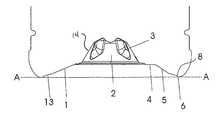
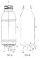
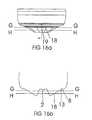
- FIG. 1shows a cross-sectional view of a hot-fill container according to one possible embodiment of the invention in its pre-collapsed condition
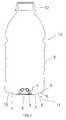
- FIG. 2shows the container of FIG. 1 in its collapsed position
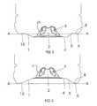
- FIG. 3shows the base of FIG. 1 before collapsing
- FIG. 4shows the base of FIG. 2 following collapsing
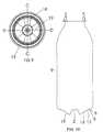
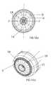
- FIG. 5shows a bottom view of the base of the container of FIG. 1 before collapsing
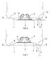
- FIG. 6shows the base of FIG. 1 before collapsing
- FIG. 7shows the base of FIG. 2 following collapsing
- FIG. 8 ashows a cross-sectional view of a hot-fill container according to an alternative embodiment of the invention in its pre-collapsed condition
- FIG. 8 bshows a cross-sectional view of the container shown in FIGS. 8 a and 9 through line C-C;
- FIG. 9shows a bottom view of the base of the container of FIGS. 8 a and 8 b and FIG. 10 before collapsing;
- FIG. 10shows a cross-sectional view of the container shown in FIG. 9 through line D-D;
- FIGS. 11 a - dshow cross-sectional views of the container according to an alternative embodiment of the invention incorporating a pusher to provide panel folding;
- FIGS. 12 a - dshow cross-sectional views of the container according to a further alternative embodiment of the invention incorporating a pusher to provide panel folding;
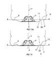
- FIG. 13Ashows the base of an alternative embodiment of the invention before collapsing
- FIG. 13Bshows the base of another alternative embodiment of the invention before collapsing
- FIG. 14shows the base of FIG. 13 during the initial stages of collapsing
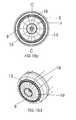
- FIGS. 15 a - bshow side and cross-sectional views of the container shown in FIG. 9 including outwardly projecting fluting;
- FIG. 15 cshows a bottom view of the base of the container of FIGS. 15 a and 15 b with dotted contour section lines through lines E-E and F-F;
- FIG. 15 dshows a perspective view of the base of the container of FIGS. 15 a - c;
- FIG. 16 ashows a side view of a container of FIG. 16 c according to an alternative embodiment including inwardly projecting fluting through Line I-I;
- FIG. 16 bshows a cross-sectional view of the base of the container of FIG. 16 c through Line J-J;
- FIG. 16 cshows a bottom view of the base of the container of FIGS. 16 a and 16 b with dotted contour section lines through lines G-G and H-H;
- FIG. 16 dshows a perspective view of the base of the container of FIGS. 16 a - c;
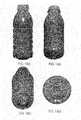
- FIGS. 17 a - dshow side, side perspective, end perspective, and end views respectively of the container of FIG. 15 ;
- FIGS. 18 a - dshow side, side perspective, end perspective, and end views respectively of the container of FIG. 16 .
- containershave typically been provided with a series of vacuum panels around their sidewalls and an optimized base portion.
- the vacuum panelsdeform inwardly, and the base deforms upwardly, under the influence of the vacuum forces. This prevents unwanted distortion elsewhere in the container.
- the containeris still subjected to internal vacuum force.
- the panels and basemerely provide a suitably resistant structure against that force. The more resistant the structure is, the more vacuum force will be present. Additionally, end users can feel the vacuum panels when holding the containers.
- the containerswill be filled with a hot liquid and then capped before being subjected to a cold water spray resulting in the formation of a vacuum within the container which the container structure needs to be able to cope with.
- the present inventionrelates to hot-fill containers and a structure that provides for the substantial removal or substantial negation of vacuum pressure. This allows much greater design freedom and light weighting opportunities as there is no longer any requirement for the structure to be resistant to vacuum forces which would otherwise mechanically distort the container. As mentioned above and in the PCT Application, various proposals for hot-fill container designs have been put forward.
- the hot-fill container of the PCT Applicationhas positioned an outwardly inclined and transversely oriented vacuum panel between the lower portion of the side wall and the inwardly domed base region. In this position, the container has poor stability, insofar as the base region is very narrow in diameter and does not allow for a good standing ring support. Additionally, there is preferably provided a decoupling structure that provides a hinge joint to the juncture of the vacuum panel and the lower sidewall. This decoupling structure provides for a larger range of longitudinal movement of the vacuum panel than would occur if the panel was coupled to the side wall by way of ribs, for example.
- the decoupling structuretherefore provides for increased deflection of the initiator portion, allowing increased movement of the panel portion longitudinally away from the previously outwardly inclined position, enabling the panel portion to fold inwardly relative to the container and upwardly relative to the initial base position.
- the lower sidewallis therefore subjected to lower force during such inversion. During this action, the base portion is translated longitudinally upward and into the container.
- the decoupling structureallows for the vacuum panel to now form part of the container base portion.
- This developmenthas at least two important advantages. Firstly, by providing the vacuum panel so as to form part of the base after folding, a mechanical force can now be provided immediately against the panel in order to apply inverting force. This allows much greater control over the action, which may, for example, be applied by a mechanical pusher, which would engage with the container base in resetting the container shape. This allows increased design options for the initiator portion.
- the transversely oriented vacuum panelis effectively completely removed from view as it is forced from an outward position to an inward position.
- the major portion of the side wall of the present inventioncould have no structural features and the container could, if required, replicate a clear wall glass container.
- any design or shapecan now be utilized, without regard for integrity against vacuum forces found in other hot-fill packages. Such a maneuver allows for a wide standing ring to be obtained.
- the decoupling structureprovides for the panel to become displaced longitudinally so that there is no contact between any part of the panel or upwardly domed base portion with the contact surface below. A standing ring is then provided by the lower sidewall immediately 20 adjacent the decoupling structure. Further, by gaining greater control over the inverting motion and forces, it is possible to allow the initiator portion to share the same steep angle as the control portion. This allows for increased volume displacement during inversion and increased resistance to any reversion back to the original position.
- FIG. 1shows, by way of example only, and in a diagrammatic cross-sectional view, a container in the form of a bottle.
- Thisis referenced generally by arrow 10 with a typical neck portion 12 and a side wall 9 extending to a lower portion of the side wall 11 and an underneath base portion 2 .
- the container 10will typically be blow molded from any suitable plastic material but typically this will be polyethylene terephthalate (PET).
- PETpolyethylene terephthalate
- the base 2is shown provided with a plurality of reinforcing ribs 3 , although this is merely by way of example only.
- FIG. 1the lower side wall portion 11 , which operates as a pressure panel, is shown in its unfolded position so that a ring or annular portion 6 is positioned above the level of the bottom of the base 2 which is forming the standing ring or support 4 for the container 10 .
- FIG. 2the lower side wall portion 11 is shown having folded inwardly so that the ring or annular portion 6 is positioned below the level of the bottom of the base 2 and is forming the new standing ring or support for the container 10 .
- the pressure panel 11can include a centrally located push-up portion 14 .
- an instep or recess 8 and decoupling structure 13immediately adjacent the ring or annular portion 6 there may be an instep or recess 8 and decoupling structure 13 , in this case a substantially flat, non-ribbed region, which after folding enables the base portion 2 to effectively completely disappear within the bottom of the container and above the line A-A.
- decoupling structure 13Many other configurations for the decoupling structure 13 are envisioned, however.
- the base 2 with its strengthening ribs 3is shown surrounded by the bottom annular portion 11 of the side wall 9 and the decoupling structure 13 .
- the lower side wall portion 11is shown in this particular embodiment as having an initiator portion 1 which forms part of the collapsing or inverting section which yields to a longitudinally-directed collapsing force before the rest of the collapsing or folding section.
- the base 2is shown provided within the typical base standing ring 4 , which will be the first support position for the container 10 prior to the inversion of the folding panel.
- a control portion 5which in this embodiment is a more steeply angled inverting section which will resist expanding from the collapsed state.
- Forming the outer perimeter of the bottom portion 11 of the side wall 9is shown the side wall standing ring or annular portion 6 which, following collapsing of the panel 11 , will provide the new container support.
- the control portion 5may be set at an angle ⁇ with respect to a plane orthogonal to the container's longitudinal axis.
- the angle ⁇ of the control portionmay be set at about 10 degrees or more.
- the angle ⁇ of the control portionmay be set at about 15 degrees or more.
- the angle ⁇may be in the range of about 30 degrees to about 45 degrees.
- the initiator portion 1can be inclined at a lesser angle of, for example, at least about 10 degrees less than the control portion.
- a lesser angle of, for example, at least about 10 degrees less than the control portionit will be appreciated that when the panel 11 is inverted by mechanical compression it will undergo an angular change that is double that provided to it.
- the conical control portion 5is set at about 15 degrees in the initial position, it can provide an angular change of approximately 30 degrees when moved to the inverted position.
- control portion 5may be initially set at an outwardly inclined angle ⁇ of approximately 35 degrees, which will provide an angular inversion of approximately 70 degrees.
- the initiator portioncan be initially set at an outward angle of approximately 20 degrees.
- the initiator portionmay be reconfigured so that control portion 18 would provide essentially a continuous conical area about the base 2 .
- the initiator portion 1 and the control portion 5will be at a common angle of inclination, such that they form a uniformly inclined panel portion.
- initiator portion 1may still be configured to provide the area of least resistance to inversion, such that although it shares the same angular of inclination as the control portion 18 , it still provides an initial area of collapse or inversion.
- initiator portion 1causes the pressure panel 11 to begin inversion from the widest diameter adjacent the decoupling structure 13 .
- the container side walls 9can be “glass-like” in construction in that there are no additional strengthening ribs or panels as might be typically found on a container, particularly if required to withstand the forces of vacuum pressure.
- structuresmay be added to the conical portions of the vacuum panel 11 in order to add further control over the inversion process.
- the conical portion of the vacuum panel 11may be divided into fluted regions.
- the panel portionscan be outwardly convex, and evenly distributed around the central axis to create alternating regions of greater angular inclination 19 and regions of lesser angular inclination 18 .
- This configurationmay provide greater control over inversion of the panel.
- This type of geometrycan provide increased resistance to reversion of the panel from the inverted position back to the initial position. Also, this type of geometry can provide a more even distribution of forces when the panel is in the inverted position.
- convex or downwardly outwardly-projecting flutesare shown.
- concave or inwardly-directed fluting arrangementsare also possible.
- the embodiment having inwardly-directed flutesmay offer less resistance to initial inverting forces, coupled with increased resistance to forces tending to revert the panel back to the initial position.
- the inwardly-directed flutescan behave in much the same manner as ribs to prevent the panel from being forced back out to the initial, outwardly-projecting position, but allow for hinge movement from the initial, outwardly-projecting position to the inwardly-directed position.
- the inwardly-directed or outwardly-projecting flutes or projectionscan function as ribs to increase the force required to invert the panel. It will be appreciated by one of ordinary skill in the art, that the forces applied to invert the panel will be sufficient to overcome any flute- or rib-strengthened panel, and that once the panel is inverted, the panel will be very resistant to reversion to the initial position, for example, if the container is dropped or shocked.
- FIGS. 16 a - d and 18 a - dconcave or inwardly-projecting flutes are shown, with the contour lines G and H of FIG. 16 c illustrating this concavity through two cross-sectional reliefs. Further embodiments comprising arrays utilizing both concave and convex flutes are also intended within the scope of the invention.
- the containermay be blow molded with the pressure panel 20 in the inwardly or upwardly inclined position.
- a forcecan be imposed on the folding panel 20 (e.g., by means of a mechanical pusher 21 introduced through the neck region and forced downwardly) in order to place the panel in the outwardly inclined position prior to use as a vacuum container.
- a vacuumis created within the filled container.
- a forcecan be imposed on the folding panel 20 in order to force the panel from the initial, outwardly-inclined position to an inwardly-inclined position.
- the forcecan be applied by means of a mechanical pusher 22 or some other external device creating relative movement of the bottle base relative to a punch or the like.
- the panel 20can be configured to invert from the initial, outwardly-inclined position to the inverted, inwardly-projecting position solely under the force of the internal vacuum developed within the container.
- a portion of the panelcan be initially resilient enough such that the panel inverts solely under the internal vacuum forces.
- any deformation of the container shape due to the internal vacuumcan be restored as a result of the internal volume reduction in the container.
- the vacuum within the containeris removed as the inversion of the panel causes a rise in pressure. Such a rise in pressure can reduce vacuum pressure until ambient pressure is reached or even a slightly positive pressure is achieved.
- the panelmay be inverted in the manner shown in FIGS. 12 a - d in order to provide accommodate internal forces such those developed during pasteurization and the like.
- the panelcan provide relief against the internal pressure generated and then be capable of accommodating the resulting vacuum force generated when the product cools down.
- the panelcan be inverted from the upwardly-inclined position as shown in FIG. 11 a to the downwardly-inclined position as shown in FIG. 12 a , except that the mechanical action is not provided.
- the forceis instead provided by the internal pressure of the contents.
- the majority of the side wall 9can be absent any structural features so that the container 10 can essentially replicate a glass container, if so desired.
- decoupling or hinge structures 13may also be provided many different decoupling or hinge structures 13 without departing from the scope of the invention. With particular reference to FIGS. 6 and 7 , it can be seen that the side of the decoupling structure 13 that is provided for the pressure panel 11 may be of an enlarged area to provide for increased longitudinal movement upwards into the container following inversion.
- the initiator portion 30 and the control portion 31can define a substantially continuous curve (as viewed in the plane of the paper), without any sharp curves or severe angles.
- the initiator portion 30can be located further from the longitudinal axis A than the control portion, that is, the initiator portion 30 can be located adjacent the wider regions of the pressure panel 11 , and the control portion 31 can be located adjacent the narrower regions of the pressure panel. The initiator portion 30 can invert earlier than the control portion 31 .
- the initiator portion 30may be constructed with this in mind (e.g., by having thinner material, or a lesser angle of inclination, than the control portion 31 ) and so on, to provide for the panel 11 to begin inverting where it has the greater diameter, ahead of the narrower sections of the panel.
- the portion 30 of the panelwhich is radially set more distant from the central axis of the container, inverts ahead of portion 31 to act as the initiator portion.
- the initiator portioncan be located closer to the longitudinal axis A than the control portion.
- the portion of the panel labeled 30 ′can serve as the initiator portion (i.e., portion 30 ′ can start inverting prior to portion 31 ).
- initiator portion 30 ′can be formed of a thinner material than control portion 31 , or, as shown, can have a smaller angle of inclination with respect to the longitudinal axis A than the control portion 31 .
- the centrally-located push-up 50can also serve as the initiator portion, provided it is formed resilient enough to initiate inversion of the pressure panel 11 .
Landscapes
- Engineering & Computer Science (AREA)
- Mechanical Engineering (AREA)
- Ceramic Engineering (AREA)
- Containers Having Bodies Formed In One Piece (AREA)
Abstract
Description
Claims (13)
Priority Applications (17)
| Application Number | Priority Date | Filing Date | Title |
|---|---|---|---|
| US11/704,338US8127955B2 (en) | 2000-08-31 | 2007-02-09 | Container structure for removal of vacuum pressure |
| US13/412,572US9145223B2 (en) | 2000-08-31 | 2012-03-05 | Container structure for removal of vacuum pressure |
| US13/415,831US9731884B2 (en) | 2000-08-31 | 2012-03-08 | Method for handling a hot-filled plastic bottle having a deep-set invertible base |
| US13/476,997US20140123603A1 (en) | 2000-08-31 | 2012-05-21 | Plastic container having a deep-set invertible base and related methods |
| US13/752,377US9969517B2 (en) | 2002-09-30 | 2013-01-28 | Systems and methods for handling plastic containers having a deep-set invertible base |
| US15/074,791US10435223B2 (en) | 2000-08-31 | 2016-03-18 | Method of handling a plastic container having a moveable base |
| US15/287,707US10683127B2 (en) | 2000-08-31 | 2016-10-06 | Plastic container having a movable base |
| US16/555,652US10611544B2 (en) | 2004-07-30 | 2019-08-29 | Method of handling a plastic container having a moveable base |
| US16/557,457US10836552B2 (en) | 2007-02-09 | 2019-08-30 | Method of handling a plastic container having a moveable base |
| US16/594,524US11565867B2 (en) | 2000-08-31 | 2019-10-07 | Method of handling a plastic container having a moveable base |
| US16/901,925US11897656B2 (en) | 2007-02-09 | 2020-06-15 | Plastic container having a movable base |
| US17/090,611US11377287B2 (en) | 2007-02-09 | 2020-11-05 | Method of handling a plastic container having a moveable base |
| US17/852,584US11731823B2 (en) | 2007-02-09 | 2022-06-29 | Method of handling a plastic container having a moveable base |
| US18/159,339US11993443B2 (en) | 2007-02-09 | 2023-01-25 | Method of handling a plastic container having a moveable base |
| US18/452,978US12179986B2 (en) | 2007-02-09 | 2023-08-21 | Method of handling a plastic container having a moveable base |
| US18/537,501US20240317447A2 (en) | 2007-02-09 | 2023-12-12 | Plastic container having a movable base |
| US18/671,257US20240308750A1 (en) | 2007-02-09 | 2024-05-22 | Method of handling a plastic container having a moveable base |
Applications Claiming Priority (12)
| Application Number | Priority Date | Filing Date | Title |
|---|---|---|---|
| NZ506684 | 2000-08-31 | ||
| NZ50668400 | 2000-08-31 | ||
| NZ512423 | 2001-06-15 | ||
| NZ51242301 | 2001-06-15 | ||
| PCT/NZ2001/000176WO2002018213A1 (en) | 2000-08-31 | 2001-08-29 | Semi-rigid collapsible container |
| US10/363,400US7077279B2 (en) | 2000-08-31 | 2001-08-29 | Semi-rigid collapsible container |
| NZ521694ANZ521694A (en) | 2002-09-30 | 2002-09-30 | Container structure for removal of vacuum pressure |
| NZ521694 | 2002-09-30 | ||
| US10/529,198US8152010B2 (en) | 2002-09-30 | 2003-09-30 | Container structure for removal of vacuum pressure |
| PCT/NZ2003/000220WO2004028910A1 (en) | 2002-09-30 | 2003-09-30 | Container structure for removal of vacuum pressure |
| US11/432,715US7717282B2 (en) | 2000-08-31 | 2006-05-12 | Semi-rigid collapsible container |
| US11/704,338US8127955B2 (en) | 2000-08-31 | 2007-02-09 | Container structure for removal of vacuum pressure |
Related Parent Applications (6)
| Application Number | Title | Priority Date | Filing Date |
|---|---|---|---|
| US10529198Continuation-In-Part | 2003-09-30 | ||
| US10/529,198Continuation-In-PartUS8152010B2 (en) | 2000-08-31 | 2003-09-30 | Container structure for removal of vacuum pressure |
| PCT/NZ2003/000220Continuation-In-PartWO2004028910A1 (en) | 2000-08-31 | 2003-09-30 | Container structure for removal of vacuum pressure |
| US11/432,715Continuation-In-PartUS7717282B2 (en) | 2000-08-31 | 2006-05-12 | Semi-rigid collapsible container |
| US11/704,318Continuation-In-PartUS20070199916A1 (en) | 2000-08-31 | 2007-02-09 | Semi-rigid collapsible container |
| US14/687,867Continuation-In-PartUS10246238B2 (en) | 2000-08-31 | 2015-04-15 | Plastic container having a deep-set invertible base and related methods |
Related Child Applications (5)
| Application Number | Title | Priority Date | Filing Date |
|---|---|---|---|
| US10/363,400Continuation-In-PartUS7077279B2 (en) | 2000-08-31 | 2001-08-29 | Semi-rigid collapsible container |
| PCT/NZ2001/000176Continuation-In-PartWO2002018213A1 (en) | 2000-08-31 | 2001-08-29 | Semi-rigid collapsible container |
| US13/412,572Continuation-In-PartUS9145223B2 (en) | 2000-08-31 | 2012-03-05 | Container structure for removal of vacuum pressure |
| US13/412,572ContinuationUS9145223B2 (en) | 2000-08-31 | 2012-03-05 | Container structure for removal of vacuum pressure |
| US13/415,831Continuation-In-PartUS9731884B2 (en) | 2000-08-31 | 2012-03-08 | Method for handling a hot-filled plastic bottle having a deep-set invertible base |
Publications (2)
| Publication Number | Publication Date |
|---|---|
| US20070199915A1 US20070199915A1 (en) | 2007-08-30 |
| US8127955B2true US8127955B2 (en) | 2012-03-06 |
Family
ID=38443015
Family Applications (2)
| Application Number | Title | Priority Date | Filing Date |
|---|---|---|---|
| US11/704,338Expired - LifetimeUS8127955B2 (en) | 2000-08-31 | 2007-02-09 | Container structure for removal of vacuum pressure |
| US13/412,572Expired - Fee RelatedUS9145223B2 (en) | 2000-08-31 | 2012-03-05 | Container structure for removal of vacuum pressure |
Family Applications After (1)
| Application Number | Title | Priority Date | Filing Date |
|---|---|---|---|
| US13/412,572Expired - Fee RelatedUS9145223B2 (en) | 2000-08-31 | 2012-03-05 | Container structure for removal of vacuum pressure |
Country Status (1)
| Country | Link |
|---|---|
| US (2) | US8127955B2 (en) |
Cited By (23)
| Publication number | Priority date | Publication date | Assignee | Title |
|---|---|---|---|---|
| US20080047964A1 (en)* | 2000-08-31 | 2008-02-28 | C02Pac | Plastic container having a deep-set invertible base and related methods |
| US20110210133A1 (en)* | 2002-09-30 | 2011-09-01 | David Melrose | Pressure reinforced plastic container and related method of processing a plastic container |
| US20110259845A1 (en)* | 2008-08-01 | 2011-10-27 | Boehringer Ingelheim International Gmbh | Package in the form of a bottle comprising a cushioning means disposed therein |
| US20120180437A1 (en)* | 2004-12-20 | 2012-07-19 | David Murray Melrose | Method of processing a container and base cup structure for removal of vacuum pressure |
| US20130068779A1 (en)* | 2002-09-30 | 2013-03-21 | David Murray Melrose | Container structure for removal of vacuum pressure |
| US20130220968A1 (en)* | 2010-10-26 | 2013-08-29 | Yoshino Kogyosho Co., Ltd. | Bottle |
| US20140069937A1 (en)* | 2000-08-31 | 2014-03-13 | Co2Pac Limited | Plastic container having a deep-set invertible base and related methods |
| USD708953S1 (en) | 2013-03-15 | 2014-07-15 | The Folger Coffee Company | Container |
| US20150136725A1 (en)* | 2012-04-17 | 2015-05-21 | Sidel Participations | Container comprising an arched base having a star-shaped cross-section |
| US9145223B2 (en) | 2000-08-31 | 2015-09-29 | Co2 Pac Limited | Container structure for removal of vacuum pressure |
| US20160031593A1 (en)* | 2014-08-01 | 2016-02-04 | North America I.M.L. Containers | Anti-depression plastic container |
| US9828166B2 (en)* | 2012-12-28 | 2017-11-28 | SOCIETE ANONYME DES EAUX MINERALES D'EVIAN et en abrégé “S.A.E.M.E.” | Self collapsible blow moulded plastic thin-walled containers and a dispensing method using same |
| US9969517B2 (en) | 2002-09-30 | 2018-05-15 | Co2Pac Limited | Systems and methods for handling plastic containers having a deep-set invertible base |
| US20180186498A1 (en)* | 2015-06-23 | 2018-07-05 | Sidel Participations | Container provided with a curved invertible diaphragm |
| US20190062026A1 (en)* | 2017-08-25 | 2019-02-28 | Graham Packaging Company, L.P. | Variable displacement base and container and method of using the same |
| US10246238B2 (en) | 2000-08-31 | 2019-04-02 | Co2Pac Limited | Plastic container having a deep-set invertible base and related methods |
| US20220289421A1 (en)* | 2008-12-31 | 2022-09-15 | Plastipak Packaging, Inc. | Hot-fillable plastic container with flexible base feature |
| US11453522B2 (en)* | 2016-02-25 | 2022-09-27 | Krones Ag | Method for shaping the bottom of hot-filled containers |
| US11565867B2 (en) | 2000-08-31 | 2023-01-31 | C02Pac Limited | Method of handling a plastic container having a moveable base |
| US11891227B2 (en) | 2019-01-15 | 2024-02-06 | Amcor Rigid Packaging Usa, Llc | Vertical displacement container base |
| US11897656B2 (en) | 2007-02-09 | 2024-02-13 | Co2Pac Limited | Plastic container having a movable base |
| US11993443B2 (en) | 2007-02-09 | 2024-05-28 | Co2Pac Limited | Method of handling a plastic container having a moveable base |
| US12129072B2 (en) | 2021-11-30 | 2024-10-29 | Pepsico, Inc. | Flexible base for aseptic-fill bottles |
Families Citing this family (42)
| Publication number | Priority date | Publication date | Assignee | Title |
|---|---|---|---|---|
| TWI228476B (en) | 2000-08-31 | 2005-03-01 | Co2 Pac Ltd | Semi-rigid collapsible container |
| US7543713B2 (en)* | 2001-04-19 | 2009-06-09 | Graham Packaging Company L.P. | Multi-functional base for a plastic, wide-mouth, blow-molded container |
| US7900425B2 (en) | 2005-10-14 | 2011-03-08 | Graham Packaging Company, L.P. | Method for handling a hot-filled container having a moveable portion to reduce a portion of a vacuum created therein |
| US6922153B2 (en)* | 2003-05-13 | 2005-07-26 | Credo Technology Corporation | Safety detection and protection system for power tools |
| NZ569422A (en)* | 2003-07-30 | 2010-02-26 | Graham Packaging Co | Container filling with base projection inverted during transportation, and being pushed up after filling |
| JP4769791B2 (en)* | 2004-03-11 | 2011-09-07 | グラハム パッケージング カンパニー,エル ピー | Plastic container transport method |
| US10611544B2 (en) | 2004-07-30 | 2020-04-07 | Co2Pac Limited | Method of handling a plastic container having a moveable base |
| US8075833B2 (en) | 2005-04-15 | 2011-12-13 | Graham Packaging Company L.P. | Method and apparatus for manufacturing blow molded containers |
| US8017065B2 (en) | 2006-04-07 | 2011-09-13 | Graham Packaging Company L.P. | System and method for forming a container having a grip region |
| US7799264B2 (en) | 2006-03-15 | 2010-09-21 | Graham Packaging Company, L.P. | Container and method for blowmolding a base in a partial vacuum pressure reduction setup |
| US9707711B2 (en) | 2006-04-07 | 2017-07-18 | Graham Packaging Company, L.P. | Container having outwardly blown, invertible deep-set grips |
| US8747727B2 (en) | 2006-04-07 | 2014-06-10 | Graham Packaging Company L.P. | Method of forming container |
| JP4882100B2 (en)* | 2006-05-15 | 2012-02-22 | 北海製罐株式会社 | Manufacturing method and apparatus for filling bottle with contents |
| FR2919579B1 (en)* | 2007-07-30 | 2011-06-17 | Sidel Participations | CONTAINER COMPRISING A BACKGROUND WITH A DEFORMABLE MEMBRANE. |
| US8627944B2 (en) | 2008-07-23 | 2014-01-14 | Graham Packaging Company L.P. | System, apparatus, and method for conveying a plurality of containers |
| AU2013270455B2 (en)* | 2008-11-27 | 2016-05-26 | Yoshino Kogyosho Co., Ltd. | Synthetic resin bottle |
| CN103057778B (en) | 2008-11-27 | 2017-04-26 | 株式会社吉野工业所 | Synthetic resin bottle |
| US8636944B2 (en) | 2008-12-08 | 2014-01-28 | Graham Packaging Company L.P. | Method of making plastic container having a deep-inset base |
| US7926243B2 (en)* | 2009-01-06 | 2011-04-19 | Graham Packaging Company, L.P. | Method and system for handling containers |
| EP2583904B1 (en)* | 2009-01-29 | 2015-03-04 | Yoshino Kogyosho Co., Ltd. | Container with folded-back bottom wall |
| EP2427381A1 (en)* | 2009-05-05 | 2012-03-14 | Amcor Rigid Plastics USA, Inc. | Panelless hot-fill plasic bottle |
| CN102639095A (en)* | 2009-10-02 | 2012-08-15 | 株式会社细川洋行 | Storing container |
| US8668100B2 (en) | 2010-06-30 | 2014-03-11 | S.C. Johnson & Son, Inc. | Bottles with top loading resistance |
| JP5501184B2 (en)* | 2010-09-30 | 2014-05-21 | 株式会社吉野工業所 | Bottle |
| CA2815075A1 (en)* | 2010-10-18 | 2012-04-26 | Plastipak Packaging, Inc. | Retort-resistant plastic container |
| US8962114B2 (en) | 2010-10-30 | 2015-02-24 | Graham Packaging Company, L.P. | Compression molded preform for forming invertible base hot-fill container, and systems and methods thereof |
| US9133006B2 (en) | 2010-10-31 | 2015-09-15 | Graham Packaging Company, L.P. | Systems, methods, and apparatuses for cooling hot-filled containers |
| USD660714S1 (en) | 2010-12-06 | 2012-05-29 | S.C. Johnson & Son, Inc. | Bottle |
| US8851311B2 (en) | 2010-12-06 | 2014-10-07 | S.C. Johnson & Son, Inc. | Bottle with top loading resistance |
| US8662329B2 (en) | 2010-12-06 | 2014-03-04 | S.C. Johnson & Son, Inc. | Bottle with top loading resistance with front and back ribs |
| FR2969987B1 (en)* | 2010-12-29 | 2013-02-01 | Sidel Participations | CORNER CONTAINER WITH INNER WAVE SIDED |
| WO2012129559A2 (en)* | 2011-03-24 | 2012-09-27 | Ring Container Technologies | Flexible panel to offset pressure differential |
| EP2726384B1 (en) | 2011-06-28 | 2017-03-15 | ABC Group Inc. | Freeze expansion surface profile |
| US9994378B2 (en) | 2011-08-15 | 2018-06-12 | Graham Packaging Company, L.P. | Plastic containers, base configurations for plastic containers, and systems, methods, and base molds thereof |
| US9150320B2 (en) | 2011-08-15 | 2015-10-06 | Graham Packaging Company, L.P. | Plastic containers having base configurations with up-stand walls having a plurality of rings, and systems, methods, and base molds thereof |
| JP5785823B2 (en)* | 2011-08-30 | 2015-09-30 | 株式会社吉野工業所 | Bottle |
| US8919587B2 (en) | 2011-10-03 | 2014-12-30 | Graham Packaging Company, L.P. | Plastic container with angular vacuum panel and method of same |
| JP6153741B2 (en)* | 2013-02-28 | 2017-06-28 | 株式会社吉野工業所 | Plastic bottle |
| US9022776B2 (en) | 2013-03-15 | 2015-05-05 | Graham Packaging Company, L.P. | Deep grip mechanism within blow mold hanger and related methods and bottles |
| US9254937B2 (en) | 2013-03-15 | 2016-02-09 | Graham Packaging Company, L.P. | Deep grip mechanism for blow mold and related methods and bottles |
| CA2939428C (en)* | 2014-02-20 | 2019-12-31 | Amcor Limited | Vacuum base for container |
| EP2957515B1 (en)* | 2014-06-18 | 2017-05-24 | Sidel Participations | Container provided with an invertible diaphragm and a central portion of greater thickness |
Citations (214)
| Publication number | Priority date | Publication date | Assignee | Title |
|---|---|---|---|---|
| US1499239A (en) | 1922-01-06 | 1924-06-24 | Malmquist Machine Company | Sheet-metal container for food |
| US2124959A (en) | 1936-08-08 | 1938-07-26 | Vogel William Martin | Method of filling and closing cans |
| US2378324A (en) | 1941-05-22 | 1945-06-12 | Kraft Cheese Company | Packaging machine |
| GB781103A (en) | 1955-02-11 | 1957-08-14 | Internat Patents Trust Ltd | Improvements in dispensing containers |
| DE1761753U (en) | 1957-11-14 | 1958-02-20 | Josef Werny Fa | TABLE. |
| US2880902A (en) | 1957-06-03 | 1959-04-07 | Owsen Peter | Collapsible article |
| US2960248A (en) | 1959-03-20 | 1960-11-15 | Arthur L Kuhlman | Block type containers |
| US2971671A (en) | 1956-10-31 | 1961-02-14 | Pabst Brewing Co | Container |
| US2982440A (en) | 1959-02-05 | 1961-05-02 | Crown Machine And Tool Company | Plastic container |
| US3043461A (en) | 1961-05-26 | 1962-07-10 | Purex Corp | Flexible plastic bottles |
| US3081002A (en)* | 1957-09-24 | 1963-03-12 | Pfrimmer & Co J | Containers for medicinal liquids |
| US3174655A (en) | 1963-01-04 | 1965-03-23 | Ampoules Inc | Drop or spray dispenser |
| US3301293A (en) | 1964-12-16 | 1967-01-31 | Owens Illinois Inc | Collapsible container |
| GB1113988A (en) | 1964-07-01 | 1968-05-15 | Charles Tennant & Company Ltd | Improvements in or relating to containers |
| US3397724A (en) | 1966-06-03 | 1968-08-20 | Phillips Petroleum Co | Thin-walled container and method of making the same |
| US3409167A (en)* | 1967-03-24 | 1968-11-05 | American Can Co | Container with flexible bottom |
| US3426939A (en) | 1966-12-07 | 1969-02-11 | William E Young | Preferentially deformable containers |
| FR1571499A (en) | 1968-05-07 | 1969-06-20 | ||
| US3468443A (en) | 1967-10-06 | 1969-09-23 | Apl Corp | Base of plastic container for storing fluids under pressure |
| US3483908A (en) | 1968-01-08 | 1969-12-16 | Monsanto Co | Container having discharging means |
| US3485355A (en) | 1968-07-03 | 1969-12-23 | Stewart Glapat Corp | Interfitting stackable bottles or similar containers |
| DE2102319A1 (en) | 1971-01-19 | 1972-08-03 | PMD Entwicklungswerk für Kunststoff-Maschinen GmbH & Co KG, 7505 Ettlingen | Disposable packaging made of plastic, in particular plastic bottles |
| US3693828A (en) | 1970-07-22 | 1972-09-26 | Crown Cork & Seal Co | Seamless steel containers |
| US3704140A (en) | 1968-12-30 | 1972-11-28 | Carnaud & Forges | Sterilisation of tins |
| US3727783A (en) | 1971-06-15 | 1973-04-17 | Du Pont | Noneverting bottom for thermoplastic bottles |
| US3819789A (en) | 1969-06-11 | 1974-06-25 | C Parker | Method and apparatus for blow molding axially deformable containers |
| US3883033A (en) | 1974-03-15 | 1975-05-13 | Roland Clough Brown | Instant twistopen can |
| US3904069A (en) | 1972-01-31 | 1975-09-09 | American Can Co | Container |
| US3918920A (en) | 1974-01-07 | 1975-11-11 | Beckman Instruments Inc | Holder for sample containers of different sizes |
| US3935955A (en) | 1975-02-13 | 1976-02-03 | Continental Can Company, Inc. | Container bottom structure |
| US3941237A (en) | 1973-12-28 | 1976-03-02 | Carter-Wallace, Inc. | Puck for and method of magnetic conveying |
| US3942673A (en) | 1974-05-10 | 1976-03-09 | National Can Corporation | Wall construction for containers |
| US3949033A (en) | 1973-11-02 | 1976-04-06 | Owens-Illinois, Inc. | Method of making a blown plastic container having a multi-axially stretch oriented concave bottom |
| US4036926A (en) | 1975-06-16 | 1977-07-19 | Owens-Illinois, Inc. | Method for blow molding a container having a concave bottom |
| US4037752A (en) | 1975-11-13 | 1977-07-26 | Coors Container Company | Container with outwardly flexible bottom end wall having integral support means and method and apparatus for manufacturing thereof |
| US4117062A (en) | 1977-06-17 | 1978-09-26 | Owens-Illinois, Inc. | Method for making a plastic container adapted to be grasped by steel drum chime-handling devices |
| US4125632A (en) | 1976-11-22 | 1978-11-14 | American Can Company | Container |
| US4170622A (en) | 1977-05-26 | 1979-10-09 | Owens-Illinois, Inc. | Method of making a blown hollow article having a ribbed interior surface |
| US4174782A (en) | 1977-02-04 | 1979-11-20 | Solvay & Cie | Hollow body made from a thermoplastic |
| US4219137A (en) | 1979-01-17 | 1980-08-26 | Hutchens Morris L | Extendable spout for a container |
| US4231483A (en) | 1977-11-10 | 1980-11-04 | Solvay & Cie. | Hollow article made of an oriented thermoplastic |
| US4247012A (en) | 1979-08-13 | 1981-01-27 | Sewell Plastics, Inc. | Bottom structure for plastic container for pressurized fluids |
| US4301933A (en) | 1979-01-10 | 1981-11-24 | Yoshino Kogyosho Co., Ltd. | Synthetic resin thin-walled bottle |
| US4318489A (en) | 1980-07-31 | 1982-03-09 | Pepsico, Inc. | Plastic bottle |
| US4318882A (en) | 1980-02-20 | 1982-03-09 | Monsanto Company | Method for producing a collapse resistant polyester container for hot fill applications |
| US4321483A (en) | 1979-10-12 | 1982-03-23 | Rockwell International Corporation | Apparatus for deriving clock pulses from return-to-zero data pulses |
| US4338765A (en) | 1979-04-16 | 1982-07-13 | Honshu Paper Co., Ltd. | Method for sealing a container |
| US4355728A (en) | 1979-01-26 | 1982-10-26 | Yoshino Kogyosho Co. Ltd. | Synthetic resin thin-walled bottle |
| US4377191A (en) | 1976-07-03 | 1983-03-22 | Kabushiki Kaisha Ekijibishon | Collapsible container |
| US4378328A (en) | 1979-04-12 | 1983-03-29 | Mauser-Werke Gmbh | Method for making chime structure for blow molded hollow member |
| US4381061A (en)* | 1981-05-26 | 1983-04-26 | Ball Corporation | Non-paneling container |
| GB2050919B (en) | 1979-06-11 | 1983-05-18 | Owens Illinois Inc | Method and apparatus for forming heat treated blown thermoplastic articles |
| USD269158S (en) | 1980-06-12 | 1983-05-31 | Plastona (John Waddington) Limited | Can or the like |
| US4386701A (en) | 1973-07-26 | 1983-06-07 | United States Steel Corporation | Tight head pail construction |
| US4412866A (en) | 1981-05-26 | 1983-11-01 | The Amalgamated Sugar Company | Method and apparatus for the sorption and separation of dissolved constituents |
| DE3215866A1 (en) | 1982-04-29 | 1983-11-03 | Seltmann, Hans-Jürgen, 2000 Hamburg | Design of plastic containers for compensating pressure variations whilst retaining good stability |
| US4436216A (en) | 1982-08-30 | 1984-03-13 | Owens-Illinois, Inc. | Ribbed base cups |
| US4444308A (en) | 1983-01-03 | 1984-04-24 | Sealright Co., Inc. | Container and dispenser for cigarettes |
| US4450878A (en) | 1978-08-12 | 1984-05-29 | Yoshino Kogyosho Co., Ltd. | Apparatus for filling a high temperature liquid into a biaxially oriented, saturated polyester bottle, a device for cooling said bottle |
| US4465199A (en) | 1981-06-22 | 1984-08-14 | Katashi Aoki | Pressure resisting plastic bottle |
| US4497855A (en) | 1980-02-20 | 1985-02-05 | Monsanto Company | Collapse resistant polyester container for hot fill applications |
| US4542029A (en) | 1981-06-19 | 1985-09-17 | American Can Company | Hot filled container |
| US4610366A (en) | 1985-11-25 | 1986-09-09 | Owens-Illinois, Inc. | Round juice bottle formed from a flexible material |
| US4628669A (en) | 1984-03-05 | 1986-12-16 | Sewell Plastics Inc. | Method of applying roll-on closures |
| US4642968A (en) | 1983-01-05 | 1987-02-17 | American Can Company | Method of obtaining acceptable configuration of a plastic container after thermal food sterilization process |
| US4645078A (en) | 1984-03-12 | 1987-02-24 | Reyner Ellis M | Tamper resistant packaging device and closure |
| US4667454A (en) | 1982-01-05 | 1987-05-26 | American Can Company | Method of obtaining acceptable configuration of a plastic container after thermal food sterilization process |
| US4684025A (en) | 1986-01-30 | 1987-08-04 | The Procter & Gamble Company | Shaped thermoformed flexible film container for granular products and method and apparatus for making the same |
| US4685273A (en) | 1981-06-19 | 1987-08-11 | American Can Company | Method of forming a long shelf-life food package |
| USD292378S (en) | 1985-04-08 | 1987-10-20 | Sewell Plastics Inc. | Bottle |
| FR2607109A1 (en) | 1986-11-24 | 1988-05-27 | Castanet Jean Noel | Bottle with variable volume, in particular made of plastic material, and its manufacturing method |
| US4749092A (en) | 1979-08-08 | 1988-06-07 | Yoshino Kogyosho Co, Ltd. | Saturated polyester resin bottle |
| US4773458A (en) | 1986-10-08 | 1988-09-27 | William Touzani | Collapsible hollow articles with improved latching and dispensing configurations |
| US4785949A (en) | 1987-12-11 | 1988-11-22 | Continental Pet Technologies, Inc. | Base configuration for an internally pressurized container |
| US4785950A (en) | 1986-03-12 | 1988-11-22 | Continental Pet Technologies, Inc. | Plastic bottle base reinforcement |
| US4807424A (en) | 1988-03-02 | 1989-02-28 | Raque Food Systems, Inc. | Packaging device and method |
| US4813556A (en) | 1986-07-11 | 1989-03-21 | Globestar Incorporated | Collapsible baby bottle with integral gripping elements and liner |
| US4831050A (en) | 1986-10-21 | 1989-05-16 | Beecham Group P.L.C. | Pyrrolidinyl benzopyrans as hypotensive agents |
| US4836398A (en)* | 1988-01-29 | 1989-06-06 | Aluminum Company Of America | Inwardly reformable endwall for a container |
| US4840289A (en) | 1988-04-29 | 1989-06-20 | Sonoco Products Company | Spin-bonded all plastic can and method of forming same |
| US4850493A (en) | 1988-06-20 | 1989-07-25 | Hoover Universal, Inc. | Blow molded bottle with self-supporting base reinforced by hollow ribs |
| US4850494A (en) | 1988-06-20 | 1989-07-25 | Hoover Universal, Inc. | Blow molded container with self-supporting base reinforced by hollow ribs |
| US4865206A (en) | 1988-06-17 | 1989-09-12 | Hoover Universal, Inc. | Blow molded one-piece bottle |
| US4867323A (en) | 1988-07-15 | 1989-09-19 | Hoover Universal, Inc. | Blow molded bottle with improved self supporting base |
| US4880129A (en)* | 1983-01-05 | 1989-11-14 | American National Can Company | Method of obtaining acceptable configuration of a plastic container after thermal food sterilization process |
| US4887730A (en) | 1987-03-27 | 1989-12-19 | William Touzani | Freshness and tamper monitoring closure |
| US4892205A (en) | 1988-07-15 | 1990-01-09 | Hoover Universal, Inc. | Concentric ribbed preform and bottle made from same |
| US4896205A (en) | 1987-07-14 | 1990-01-23 | Rockwell International Corporation | Compact reduced parasitic resonant frequency pulsed power source at microwave frequencies |
| US4921147A (en) | 1989-02-06 | 1990-05-01 | Michel Poirier | Pouring spout |
| US4967538A (en) | 1988-01-29 | 1990-11-06 | Aluminum Company Of America | Inwardly reformable endwall for a container and a method of packaging a product in the container |
| US4976538A (en) | 1988-08-05 | 1990-12-11 | Spectra-Physics, Inc. | Detection and display device |
| US4978015A (en) | 1990-01-10 | 1990-12-18 | North American Container, Inc. | Plastic container for pressurized fluids |
| US4997692A (en) | 1982-01-29 | 1991-03-05 | Yoshino Kogyosho Co., Ltd. | Synthetic resin made thin-walled bottle |
| US5004109A (en) | 1988-02-19 | 1991-04-02 | Broadway Companies, Inc. | Blown plastic container having an integral single thickness skirt of bi-axially oriented PET |
| US5005716A (en) | 1988-06-24 | 1991-04-09 | Hoover Universal, Inc. | Polyester container for hot fill liquids |
| US5014868A (en) | 1986-04-08 | 1991-05-14 | Ccl Custom Manufacturing, Inc. | Holding device for containers |
| US5024340A (en) | 1990-07-23 | 1991-06-18 | Sewell Plastics, Inc. | Wide stance footed bottle |
| US5060453A (en) | 1990-07-23 | 1991-10-29 | Sewell Plastics, Inc. | Hot fill container with reconfigurable convex volume control panel |
| US5067622A (en) | 1989-11-13 | 1991-11-26 | Van Dorn Company | Pet container for hot filled applications |
| US5090180A (en) | 1988-12-29 | 1992-02-25 | A/S Haustrup Plastic | Method and apparatus for producing sealed and filled containers |
| US5092474A (en) | 1990-08-01 | 1992-03-03 | Kraft General Foods, Inc. | Plastic jar |
| US5133468A (en) | 1991-06-14 | 1992-07-28 | Constar Plastics Inc. | Footed hot-fill container |
| US5141121A (en) | 1991-03-18 | 1992-08-25 | Hoover Universal, Inc. | Hot fill plastic container with invertible vacuum collapse surfaces in the hand grips |
| US5178290A (en) | 1985-07-30 | 1993-01-12 | Yoshino-Kogyosho Co., Ltd. | Container having collapse panels with indentations and reinforcing ribs |
| CA2077717A1 (en) | 1991-09-13 | 1993-03-14 | William E. Fillmore | Dispenser package for dual viscous products |
| US5199587A (en) | 1985-04-17 | 1993-04-06 | Yoshino Kogyosho Co., Ltd. | Biaxial-orientation blow-molded bottle-shaped container with axial ribs |
| US5199588A (en) | 1988-04-01 | 1993-04-06 | Yoshino Kogyosho Co., Ltd. | Biaxially blow-molded bottle-shaped container having pressure responsive walls |
| US5201438A (en) | 1992-05-20 | 1993-04-13 | Norwood Peter M | Collapsible faceted container |
| US5217737A (en) | 1991-05-20 | 1993-06-08 | Abbott Laboratories | Plastic containers capable of surviving sterilization |
| US5234126A (en) | 1991-01-04 | 1993-08-10 | Abbott Laboratories | Plastic container |
| US5244106A (en) | 1991-02-08 | 1993-09-14 | Takacs Peter S | Bottle incorporating cap holder |
| US5251424A (en) | 1991-01-11 | 1993-10-12 | American National Can Company | Method of packaging products in plastic containers |
| US5255889A (en) | 1991-11-15 | 1993-10-26 | Continental Pet Technologies, Inc. | Modular wold |
| US5261544A (en) | 1992-09-30 | 1993-11-16 | Kraft General Foods, Inc. | Container for viscous products |
| US5279433A (en) | 1992-02-26 | 1994-01-18 | Continental Pet Technologies, Inc. | Panel design for a hot-fillable container |
| US5281387A (en) | 1992-07-07 | 1994-01-25 | Continental Pet Technologies, Inc. | Method of forming a container having a low crystallinity |
| US5333761A (en) | 1992-03-16 | 1994-08-02 | Ballard Medical Products | Collapsible bottle |
| US5341946A (en) | 1993-03-26 | 1994-08-30 | Hoover Universal, Inc. | Hot fill plastic container having reinforced pressure absorption panels |
| US5392937A (en) | 1993-09-03 | 1995-02-28 | Graham Packaging Corporation | Flex and grip panel structure for hot-fillable blow-molded container |
| NZ240448A (en) | 1991-11-01 | 1995-06-27 | Co2Pac Limited Substituted For | Semi-rigid collapsible container; side wall has folding portion having plurality of panels |
| EP0666222A1 (en) | 1994-02-03 | 1995-08-09 | The Procter & Gamble Company | Air tight containers, able to be reversibly and gradually pressurized, and assembly thereof |
| US5454481A (en) | 1994-06-29 | 1995-10-03 | Pan Asian Plastics Corporation | Integrally blow molded container having radial base reinforcement structure |
| US5472181A (en) | 1994-04-18 | 1995-12-05 | Pitney Bowes Inc. | System and apparatus for accumulating and stitching sheets |
| US5472105A (en) | 1994-10-28 | 1995-12-05 | Continental Pet Technologies, Inc. | Hot-fillable plastic container with end grip |
| US5484052A (en) | 1994-05-06 | 1996-01-16 | Dowbrands L.P. | Carrier puck |
| US5503283A (en) | 1994-11-14 | 1996-04-02 | Graham Packaging Corporation | Blow-molded container base structure |
| EP0521642B1 (en) | 1991-07-04 | 1996-12-27 | CarnaudMetalbox plc | Method of filling a can and can for use therein |
| US5593063A (en)* | 1992-07-30 | 1997-01-14 | Carnaudmetalbox Plc | Deformable end wall for a pressure-resistant container |
| US5598941A (en) | 1995-08-08 | 1997-02-04 | Graham Packaging Corporation | Grip panel structure for high-speed hot-fillable blow-molded container |
| US5632397A (en) | 1993-09-21 | 1997-05-27 | Societe Anonyme Des Eaux Minerales D'evian | Axially-crushable bottle made of plastics material, and tooling for manufacturing it |
| US5642826A (en)* | 1991-11-01 | 1997-07-01 | Co2Pac Limited | Collapsible container |
| US5672730A (en) | 1995-09-22 | 1997-09-30 | The Goodyear Tire & Rubber Company | Thiopropionate synergists |
| US5690244A (en) | 1995-12-20 | 1997-11-25 | Plastipak Packaging, Inc. | Blow molded container having paneled side wall |
| US5704504A (en) | 1993-09-02 | 1998-01-06 | Rhodia-Ster Fipack S.A. | Plastic bottle for hot filling |
| US5713480A (en) | 1994-03-16 | 1998-02-03 | Societe Anonyme Des Eaux Minerales D'evian | Molded plastics bottle and a mold for making it |
| US5730314A (en) | 1995-05-26 | 1998-03-24 | Anheuser-Busch Incorporated | Controlled growth can with two configurations |
| US5730914A (en) | 1995-03-27 | 1998-03-24 | Ruppman, Sr.; Kurt H. | Method of making a molded plastic container |
| US5737827A (en) | 1994-09-12 | 1998-04-14 | Hitachi, Ltd. | Automatic assembling system |
| US5758802A (en) | 1996-09-06 | 1998-06-02 | Dart Industries Inc. | Icing set |
| US5762221A (en) | 1996-07-23 | 1998-06-09 | Graham Packaging Corporation | Hot-fillable, blow-molded plastic container having a reinforced dome |
| US5780130A (en) | 1994-10-27 | 1998-07-14 | The Coca-Cola Company | Container and method of making container from polyethylene naphthalate and copolymers thereof |
| US5785197A (en) | 1996-04-01 | 1998-07-28 | Plastipak Packaging, Inc. | Reinforced central base structure for a plastic container |
| US5819507A (en) | 1994-12-05 | 1998-10-13 | Tetra Laval Holdings & Finance S.A. | Method of filling a packaging container |
| NZ296014A (en) | 1994-10-28 | 1998-10-28 | Continental Pet Technologies | Hot fillable plastics container comprises vacuum panels between ribbed post walls and ribbed lands above and below |
| US5829614A (en) | 1992-07-07 | 1998-11-03 | Continental Pet Technologies, Inc. | Method of forming container with high-crystallinity sidewall and low-crystallinity base |
| US5858300A (en) | 1994-02-23 | 1999-01-12 | Denki Kagaku Kogyo Kabushiki Kaisha | Self-sustaining container |
| US5860556A (en) | 1996-04-10 | 1999-01-19 | Robbins, Iii; Edward S. | Collapsible storage container |
| US5888598A (en) | 1996-07-23 | 1999-03-30 | The Coca-Cola Company | Preform and bottle using pet/pen blends and copolymers |
| US5887739A (en) | 1997-10-03 | 1999-03-30 | Graham Packaging Company, L.P. | Ovalization and crush resistant container |
| US5897090A (en) | 1997-11-13 | 1999-04-27 | Bayer Corporation | Puck for a sample tube |
| US5906286A (en) | 1995-03-28 | 1999-05-25 | Toyo Seikan Kaisha, Ltd. | Heat-resistant pressure-resistant and self standing container and method of producing thereof |
| US5908128A (en)* | 1995-07-17 | 1999-06-01 | Continental Pet Technologies, Inc. | Pasteurizable plastic container |
| USD415030S (en) | 1997-06-12 | 1999-10-12 | Calix Technology Limited | Beverage container |
| NZ335565A (en) | 1998-06-04 | 1999-10-28 | Twinpak Inc | Hot fill plastic container with recessed vacuum panels and bands, with hoop ribs each composed of a plurality of recessesd rib sections, above and below the panels |
| US5976653A (en) | 1992-07-07 | 1999-11-02 | Continental Pet Technologies, Inc. | Multilayer preform and container with polyethylene naphthalate (PEN), and method of forming same |
| USRE36639E (en) | 1986-02-14 | 2000-04-04 | North American Container, Inc. | Plastic container |
| US6065624A (en) | 1998-10-29 | 2000-05-23 | Plastipak Packaging, Inc. | Plastic blow molded water bottle |
| JP2000168756A (en) | 1998-11-30 | 2000-06-20 | Sekisui Seikei Ltd | Compact blow container having bellows |
| US6105815A (en) | 1996-12-11 | 2000-08-22 | Mazda; Masayosi | Contraction-controlled bellows container |
| JP2000229615A (en) | 1999-02-10 | 2000-08-22 | Mitsubishi Plastics Ind Ltd | Plastic bottle |
| EP1063076A1 (en) | 1998-12-28 | 2000-12-27 | A.K. Technical Laboratory, Inc., | Wide-mouthed container bottom molding method using stretch blow molding |
| US6176382B1 (en)* | 1998-10-14 | 2001-01-23 | American National Can Company | Plastic container having base with annular wall and method of making the same |
| US6213325B1 (en) | 1998-07-10 | 2001-04-10 | Crown Cork & Seal Technologies Corporation | Footed container and base therefor |
| US6230912B1 (en) | 1999-08-12 | 2001-05-15 | Pechinery Emballage Flexible Europe | Plastic container with horizontal annular ribs |
| US6277321B1 (en) | 1998-04-09 | 2001-08-21 | Schmalbach-Lubeca Ag | Method of forming wide-mouth, heat-set, pinch-grip containers |
| US6290094B1 (en) | 1996-03-08 | 2001-09-18 | Graham Packaging Company, L.P. | Integrally blow-molded container and closure |
| US6298638B1 (en) | 1997-04-21 | 2001-10-09 | Graham Packaging Company, L.P. | System for blow-molding, filling and capping containers |
| US20010035391A1 (en) | 1990-11-15 | 2001-11-01 | Plastipak Packaging, Inc. | Plastic blow molded freestanding container |
| US6375025B1 (en) | 1999-08-13 | 2002-04-23 | Graham Packaging Company, L.P. | Hot-fillable grip container |
| JP2002127237A (en) | 2000-10-27 | 2002-05-08 | Frontier:Kk | Blow molding method |
| US6390316B1 (en) | 1999-08-13 | 2002-05-21 | Graham Packaging Company, L.P. | Hot-fillable wide-mouth grip jar |
| US20020074336A1 (en) | 2000-07-24 | 2002-06-20 | Silvers Kerry W. | Container base structure |
| US6413466B1 (en) | 2000-06-30 | 2002-07-02 | Schmalbach-Lubeca Ag | Plastic container having geometry minimizing spherulitic crystallization below the finish and method |
| US20020096486A1 (en) | 2001-01-22 | 2002-07-25 | Bourque Raymond A. | Container with integrated vacuum panel, logo and grip portion |
| US6439413B1 (en) | 2000-02-29 | 2002-08-27 | Graham Packaging Company, L.P. | Hot-fillable and retortable flat paneled jar |
| GB2372977A (en) | 2000-11-14 | 2002-09-11 | Barrie Henry Loveday | Adjustable airtight container |
| US20020153343A1 (en) | 2001-04-19 | 2002-10-24 | Tobias John W. | Multi-functional base for a plastic, wide-mouth, blow-molded container |
| US20020158038A1 (en) | 2001-03-16 | 2002-10-31 | Timothy Heisel | Retortable plastic container |
| US6485669B1 (en) | 1999-09-14 | 2002-11-26 | Schmalbach-Lubeca Ag | Blow molding method for producing pasteurizable containers |
| US6502369B1 (en) | 2000-10-25 | 2003-01-07 | Amcor Twinpak-North America Inc. | Method of supporting plastic containers during product filling and packaging when exposed to elevated temperatures and internal pressure variations |
| US20030015491A1 (en) | 2001-07-17 | 2003-01-23 | Melrose David Murray | Plastic container having an inverted active cage |
| US6514451B1 (en) | 2000-06-30 | 2003-02-04 | Schmalbach-Lubeca Ag | Method for producing plastic containers having high crystallinity bases |
| US20030186006A1 (en) | 1996-03-07 | 2003-10-02 | Continental Pet Technologies, Inc. | Multilayer container resistant to elevated temperatures and pressures, and method of making the same |
| US20030196926A1 (en) | 2001-04-19 | 2003-10-23 | Tobias John W. | Multi-functional base for a plastic, wide-mouth, blow-molded container |
| US20030217947A1 (en) | 2002-05-01 | 2003-11-27 | Kao Corporation | Article holder |
| US6662960B2 (en) | 2001-02-05 | 2003-12-16 | Graham Packaging Company, L.P. | Blow molded slender grippable bottle dome with flex panels |
| US20040016716A1 (en) | 2001-06-27 | 2004-01-29 | Melrose David M. | Hot-fillable multi-sided blow-molded container |
| US6749780B2 (en) | 2000-06-27 | 2004-06-15 | Graham Packaging Company, L.P. | Preform and method for manufacturing a multi-layer blown finish container |
| US6763968B1 (en) | 2000-06-30 | 2004-07-20 | Schmalbach-Lubeca Ag | Base portion of a plastic container |
| US6769561B2 (en) | 2001-12-21 | 2004-08-03 | Ball Corporation | Plastic bottle with champagne base |
| US20040149677A1 (en)* | 2003-01-30 | 2004-08-05 | Slat William A. | Hot fillable container with flexible base portion |
| US20040173656A1 (en) | 2003-03-05 | 2004-09-09 | Seong Song Eun | Cushion members for a back support |
| US20040173565A1 (en) | 1999-12-01 | 2004-09-09 | Frank Semersky | Pasteurizable wide-mouth container |
| US20040211746A1 (en) | 2001-04-19 | 2004-10-28 | Graham Packaging Company, L.P. | Multi-functional base for a plastic, wide-mouth, blow-molded container |
| EP0957030B1 (en) | 1998-04-09 | 2005-05-18 | Rexam Ab | Plastic container |
| NZ521694A (en) | 2002-09-30 | 2005-05-27 | Co2 Pac Ltd | Container structure for removal of vacuum pressure |
| US6942116B2 (en)* | 2003-05-23 | 2005-09-13 | Amcor Limited | Container base structure responsive to vacuum related forces |
| US20060006133A1 (en) | 2003-05-23 | 2006-01-12 | Lisch G D | Container base structure responsive to vacuum related forces |
| US7051889B2 (en) | 2001-04-03 | 2006-05-30 | Sidel | Thermoplastic container whereof the base comprises a cross-shaped impression |
| US7077279B2 (en) | 2000-08-31 | 2006-07-18 | Co2 Pac Limited | Semi-rigid collapsible container |
| US20060231985A1 (en) | 2005-04-15 | 2006-10-19 | Graham Packaging Company, Lp | Method and apparatus for manufacturing blow molded containers |
| US20060255005A1 (en) | 2002-09-30 | 2006-11-16 | Co2 Pac Limited | Pressure reinforced plastic container and related method of processing a plastic container |
| US7137520B1 (en) | 1999-02-25 | 2006-11-21 | David Murray Melrose | Container having pressure responsive panels |
| US7150372B2 (en) | 2003-05-23 | 2006-12-19 | Amcor Limited | Container base structure responsive to vacuum related forces |
| US7159374B2 (en) | 2003-11-10 | 2007-01-09 | Inoflate, Llc | Method and device for pressurizing containers |
| US20070051073A1 (en) | 2003-07-30 | 2007-03-08 | Graham Packaging Company, L.P. | Container handling system |
| US20070084821A1 (en) | 2005-10-14 | 2007-04-19 | Graham Packaging Company, L.P. | Repositionable base structure for a container |
| US20070125743A1 (en) | 2005-12-02 | 2007-06-07 | Graham Packaging Company, L.P. | Multi-sided spiraled plastic container |
| US20070181403A1 (en) | 2004-03-11 | 2007-08-09 | Graham Packaging Company, Lp. | Process and device for conveying odd-shaped containers |
| US20070199915A1 (en) | 2000-08-31 | 2007-08-30 | C02Pac | Container structure for removal of vacuum pressure |
| US20070215571A1 (en) | 2006-03-15 | 2007-09-20 | Graham Packaging Company, L.P. | Container and method for blowmolding a base in a partial vacuum pressure reduction setup |
| US20070235905A1 (en) | 2006-04-07 | 2007-10-11 | Graham Packaging Company L.P. | System and method for forming a container having a grip region |
| US20080047964A1 (en) | 2000-08-31 | 2008-02-28 | C02Pac | Plastic container having a deep-set invertible base and related methods |
| JP4831050B2 (en) | 2007-10-31 | 2011-12-07 | トヨタ自動車株式会社 | Vehicle start control device |
Family Cites Families (31)
| Publication number | Priority date | Publication date | Assignee | Title |
|---|---|---|---|---|
| DE1302048B (en) | 1967-04-08 | 1969-10-16 | Tedeco Verpackung Gmbh | Plastic container |
| JPS4928628Y1 (en) | 1969-06-12 | 1974-08-03 | ||
| JPS4831050U (en) | 1971-08-19 | 1973-04-16 | ||
| JPS5472181U (en) | 1977-10-31 | 1979-05-22 | ||
| JPS5919618Y2 (en) | 1979-02-07 | 1984-06-07 | 日野車体工業株式会社 | Door bag device for the rear door for getting on and off a bus |
| JPS5672730U (en) | 1979-11-05 | 1981-06-15 | ||
| JPS60182847A (en) | 1984-03-01 | 1985-09-18 | Matsushita Electric Ind Co Ltd | Copy machine |
| JPH0343342Y2 (en) | 1985-04-01 | 1991-09-11 | ||
| JPH0434827Y2 (en) | 1987-05-28 | 1992-08-19 | ||
| JPS649146U (en) | 1987-07-08 | 1989-01-18 | ||
| US5064080A (en) | 1990-11-15 | 1991-11-12 | Plastipak Packaging, Inc. | Plastic blow molded freestanding container |
| RU2021956C1 (en) | 1990-12-11 | 1994-10-30 | Эдуард Ильич Карагезов | Reservoir for a bottle with drink |
| US5289614A (en)* | 1992-08-21 | 1994-03-01 | The United States Of America As Represented By The United States National Aeronautics And Space Administration | Extra-vehicular activity translation tool |
| JPH09193U (en) | 1992-08-31 | 1997-04-08 | 株式会社エヌテック | Container |
| JPH06336238A (en) | 1993-05-24 | 1994-12-06 | Mitsubishi Plastics Ind Ltd | Plastic bottle |
| AU1495395A (en) | 1994-04-29 | 1995-11-09 | Constar Plastics Inc. | Plastic bottle having enhanced sculptured surface appearance |
| JPH08253220A (en) | 1995-03-20 | 1996-10-01 | Morishita Roussel Kk | Plastic bottle containing aqueous solution |
| CA2177803A1 (en)* | 1995-06-01 | 1996-12-02 | Robert H. Moore | Nip pressure sensing system |
| JP3067599B2 (en) | 1995-07-26 | 2000-07-17 | 東洋製罐株式会社 | Heat-resistant pressure-resistant self-standing container |
| JPH09110045A (en) | 1995-10-13 | 1997-04-28 | Takuya Shintani | Expansible/contracticle container |
| AUPN605595A0 (en) | 1995-10-19 | 1995-11-09 | Amcor Limited | A hot fill container |
| CA2248957A1 (en) | 1996-03-19 | 1997-09-25 | Graham Packaging Corporation | Blow-molded container having label mount regions separated by peripherally spaced ribs |
| JPH10167226A (en) | 1996-12-10 | 1998-06-23 | Daiwa Can Co Ltd | Aseptic filling equipment for plastic bottles |
| JPH10181734A (en) | 1996-12-25 | 1998-07-07 | Aokiko Kenkyusho:Kk | Bottom structure of container such as thin synthetic resin bottle |
| JP3808160B2 (en) | 1997-02-19 | 2006-08-09 | 株式会社吉野工業所 | Plastic bottle |
| US5971184A (en) | 1997-10-28 | 1999-10-26 | Continental Pet Technologies, Inc. | Hot-fillable plastic container with grippable body |
| US6228317B1 (en)* | 1998-07-30 | 2001-05-08 | Graham Packaging Company, L.P. | Method of making wide mouth blow molded container |
| ATE274452T1 (en) | 1999-03-01 | 2004-09-15 | Graham Packaging Co | STERILIZABLE HOT FILL CONTAINERS WITH FLAT SIDES |
| EP1282569B1 (en) | 1999-12-01 | 2005-09-07 | Graham Packaging Company, L.P. | Pasteurizable wide-mouth container |
| JP4077596B2 (en)* | 2000-05-31 | 2008-04-16 | 中島工業株式会社 | Transfer material having low reflective layer and method for producing molded product using the same |
| PE20061467A1 (en) | 2005-04-15 | 2007-03-09 | Graham Packaging Co | SYSTEM AND METHOD TO MANUFACTURE BLOW-MOLDED CONTAINERS WITH OPTIMAL PLASTIC DISTRIBUTION |
- 2007
- 2007-02-09USUS11/704,338patent/US8127955B2/ennot_activeExpired - Lifetime
- 2012
- 2012-03-05USUS13/412,572patent/US9145223B2/ennot_activeExpired - Fee Related
Patent Citations (236)
| Publication number | Priority date | Publication date | Assignee | Title |
|---|---|---|---|---|
| US1499239A (en) | 1922-01-06 | 1924-06-24 | Malmquist Machine Company | Sheet-metal container for food |
| US2124959A (en) | 1936-08-08 | 1938-07-26 | Vogel William Martin | Method of filling and closing cans |
| US2378324A (en) | 1941-05-22 | 1945-06-12 | Kraft Cheese Company | Packaging machine |
| GB781103A (en) | 1955-02-11 | 1957-08-14 | Internat Patents Trust Ltd | Improvements in dispensing containers |
| US2971671A (en) | 1956-10-31 | 1961-02-14 | Pabst Brewing Co | Container |
| US2880902A (en) | 1957-06-03 | 1959-04-07 | Owsen Peter | Collapsible article |
| US3081002A (en)* | 1957-09-24 | 1963-03-12 | Pfrimmer & Co J | Containers for medicinal liquids |
| DE1761753U (en) | 1957-11-14 | 1958-02-20 | Josef Werny Fa | TABLE. |
| US2982440A (en) | 1959-02-05 | 1961-05-02 | Crown Machine And Tool Company | Plastic container |
| US2960248A (en) | 1959-03-20 | 1960-11-15 | Arthur L Kuhlman | Block type containers |
| US3043461A (en) | 1961-05-26 | 1962-07-10 | Purex Corp | Flexible plastic bottles |
| US3174655A (en) | 1963-01-04 | 1965-03-23 | Ampoules Inc | Drop or spray dispenser |
| GB1113988A (en) | 1964-07-01 | 1968-05-15 | Charles Tennant & Company Ltd | Improvements in or relating to containers |
| US3301293A (en) | 1964-12-16 | 1967-01-31 | Owens Illinois Inc | Collapsible container |
| US3397724A (en) | 1966-06-03 | 1968-08-20 | Phillips Petroleum Co | Thin-walled container and method of making the same |
| US3426939A (en) | 1966-12-07 | 1969-02-11 | William E Young | Preferentially deformable containers |
| US3409167A (en)* | 1967-03-24 | 1968-11-05 | American Can Co | Container with flexible bottom |
| US3468443A (en) | 1967-10-06 | 1969-09-23 | Apl Corp | Base of plastic container for storing fluids under pressure |
| US3483908A (en) | 1968-01-08 | 1969-12-16 | Monsanto Co | Container having discharging means |
| FR1571499A (en) | 1968-05-07 | 1969-06-20 | ||
| US3485355A (en) | 1968-07-03 | 1969-12-23 | Stewart Glapat Corp | Interfitting stackable bottles or similar containers |
| US3704140A (en) | 1968-12-30 | 1972-11-28 | Carnaud & Forges | Sterilisation of tins |
| US3819789A (en) | 1969-06-11 | 1974-06-25 | C Parker | Method and apparatus for blow molding axially deformable containers |
| US3693828A (en) | 1970-07-22 | 1972-09-26 | Crown Cork & Seal Co | Seamless steel containers |
| DE2102319A1 (en) | 1971-01-19 | 1972-08-03 | PMD Entwicklungswerk für Kunststoff-Maschinen GmbH & Co KG, 7505 Ettlingen | Disposable packaging made of plastic, in particular plastic bottles |
| US3727783A (en) | 1971-06-15 | 1973-04-17 | Du Pont | Noneverting bottom for thermoplastic bottles |
| US3904069A (en) | 1972-01-31 | 1975-09-09 | American Can Co | Container |
| US4386701A (en) | 1973-07-26 | 1983-06-07 | United States Steel Corporation | Tight head pail construction |
| US3949033A (en) | 1973-11-02 | 1976-04-06 | Owens-Illinois, Inc. | Method of making a blown plastic container having a multi-axially stretch oriented concave bottom |
| US3941237A (en) | 1973-12-28 | 1976-03-02 | Carter-Wallace, Inc. | Puck for and method of magnetic conveying |
| US3918920A (en) | 1974-01-07 | 1975-11-11 | Beckman Instruments Inc | Holder for sample containers of different sizes |
| US3883033A (en) | 1974-03-15 | 1975-05-13 | Roland Clough Brown | Instant twistopen can |
| US3942673A (en) | 1974-05-10 | 1976-03-09 | National Can Corporation | Wall construction for containers |
| US3935955A (en) | 1975-02-13 | 1976-02-03 | Continental Can Company, Inc. | Container bottom structure |
| US4036926A (en) | 1975-06-16 | 1977-07-19 | Owens-Illinois, Inc. | Method for blow molding a container having a concave bottom |
| US4134510A (en) | 1975-06-16 | 1979-01-16 | Owens-Illinois, Inc. | Bottle having ribbed bottom |
| US4037752A (en) | 1975-11-13 | 1977-07-26 | Coors Container Company | Container with outwardly flexible bottom end wall having integral support means and method and apparatus for manufacturing thereof |
| US4377191A (en) | 1976-07-03 | 1983-03-22 | Kabushiki Kaisha Ekijibishon | Collapsible container |
| US4125632A (en) | 1976-11-22 | 1978-11-14 | American Can Company | Container |
| US4174782A (en) | 1977-02-04 | 1979-11-20 | Solvay & Cie | Hollow body made from a thermoplastic |
| US4170622A (en) | 1977-05-26 | 1979-10-09 | Owens-Illinois, Inc. | Method of making a blown hollow article having a ribbed interior surface |
| US4117062A (en) | 1977-06-17 | 1978-09-26 | Owens-Illinois, Inc. | Method for making a plastic container adapted to be grasped by steel drum chime-handling devices |
| US4231483A (en) | 1977-11-10 | 1980-11-04 | Solvay & Cie. | Hollow article made of an oriented thermoplastic |
| US4450878A (en) | 1978-08-12 | 1984-05-29 | Yoshino Kogyosho Co., Ltd. | Apparatus for filling a high temperature liquid into a biaxially oriented, saturated polyester bottle, a device for cooling said bottle |
| US4301933A (en) | 1979-01-10 | 1981-11-24 | Yoshino Kogyosho Co., Ltd. | Synthetic resin thin-walled bottle |
| US4219137A (en) | 1979-01-17 | 1980-08-26 | Hutchens Morris L | Extendable spout for a container |
| US4355728A (en) | 1979-01-26 | 1982-10-26 | Yoshino Kogyosho Co. Ltd. | Synthetic resin thin-walled bottle |
| US4378328A (en) | 1979-04-12 | 1983-03-29 | Mauser-Werke Gmbh | Method for making chime structure for blow molded hollow member |
| US4338765A (en) | 1979-04-16 | 1982-07-13 | Honshu Paper Co., Ltd. | Method for sealing a container |
| GB2050919B (en) | 1979-06-11 | 1983-05-18 | Owens Illinois Inc | Method and apparatus for forming heat treated blown thermoplastic articles |
| US4749092A (en) | 1979-08-08 | 1988-06-07 | Yoshino Kogyosho Co, Ltd. | Saturated polyester resin bottle |
| US4247012A (en) | 1979-08-13 | 1981-01-27 | Sewell Plastics, Inc. | Bottom structure for plastic container for pressurized fluids |
| US4321483A (en) | 1979-10-12 | 1982-03-23 | Rockwell International Corporation | Apparatus for deriving clock pulses from return-to-zero data pulses |
| US4318882A (en) | 1980-02-20 | 1982-03-09 | Monsanto Company | Method for producing a collapse resistant polyester container for hot fill applications |
| US4497855A (en) | 1980-02-20 | 1985-02-05 | Monsanto Company | Collapse resistant polyester container for hot fill applications |
| USD269158S (en) | 1980-06-12 | 1983-05-31 | Plastona (John Waddington) Limited | Can or the like |
| US4318489A (en) | 1980-07-31 | 1982-03-09 | Pepsico, Inc. | Plastic bottle |
| US4381061A (en)* | 1981-05-26 | 1983-04-26 | Ball Corporation | Non-paneling container |
| US4412866A (en) | 1981-05-26 | 1983-11-01 | The Amalgamated Sugar Company | Method and apparatus for the sorption and separation of dissolved constituents |
| US4542029A (en) | 1981-06-19 | 1985-09-17 | American Can Company | Hot filled container |
| US4685273A (en) | 1981-06-19 | 1987-08-11 | American Can Company | Method of forming a long shelf-life food package |
| US4465199A (en) | 1981-06-22 | 1984-08-14 | Katashi Aoki | Pressure resisting plastic bottle |
| US4667454A (en) | 1982-01-05 | 1987-05-26 | American Can Company | Method of obtaining acceptable configuration of a plastic container after thermal food sterilization process |
| US4997692A (en) | 1982-01-29 | 1991-03-05 | Yoshino Kogyosho Co., Ltd. | Synthetic resin made thin-walled bottle |
| DE3215866A1 (en) | 1982-04-29 | 1983-11-03 | Seltmann, Hans-Jürgen, 2000 Hamburg | Design of plastic containers for compensating pressure variations whilst retaining good stability |
| US4436216A (en) | 1982-08-30 | 1984-03-13 | Owens-Illinois, Inc. | Ribbed base cups |
| US4444308A (en) | 1983-01-03 | 1984-04-24 | Sealright Co., Inc. | Container and dispenser for cigarettes |
| US4642968A (en) | 1983-01-05 | 1987-02-17 | American Can Company | Method of obtaining acceptable configuration of a plastic container after thermal food sterilization process |
| US4880129A (en)* | 1983-01-05 | 1989-11-14 | American National Can Company | Method of obtaining acceptable configuration of a plastic container after thermal food sterilization process |
| US4628669A (en) | 1984-03-05 | 1986-12-16 | Sewell Plastics Inc. | Method of applying roll-on closures |
| US4645078A (en) | 1984-03-12 | 1987-02-24 | Reyner Ellis M | Tamper resistant packaging device and closure |
| USD292378S (en) | 1985-04-08 | 1987-10-20 | Sewell Plastics Inc. | Bottle |
| US5199587A (en) | 1985-04-17 | 1993-04-06 | Yoshino Kogyosho Co., Ltd. | Biaxial-orientation blow-molded bottle-shaped container with axial ribs |
| US5178290A (en) | 1985-07-30 | 1993-01-12 | Yoshino-Kogyosho Co., Ltd. | Container having collapse panels with indentations and reinforcing ribs |
| US4610366A (en) | 1985-11-25 | 1986-09-09 | Owens-Illinois, Inc. | Round juice bottle formed from a flexible material |
| US4684025A (en) | 1986-01-30 | 1987-08-04 | The Procter & Gamble Company | Shaped thermoformed flexible film container for granular products and method and apparatus for making the same |
| USRE36639E (en) | 1986-02-14 | 2000-04-04 | North American Container, Inc. | Plastic container |
| US4785950A (en) | 1986-03-12 | 1988-11-22 | Continental Pet Technologies, Inc. | Plastic bottle base reinforcement |
| US5014868A (en) | 1986-04-08 | 1991-05-14 | Ccl Custom Manufacturing, Inc. | Holding device for containers |
| US4813556A (en) | 1986-07-11 | 1989-03-21 | Globestar Incorporated | Collapsible baby bottle with integral gripping elements and liner |
| US4773458A (en) | 1986-10-08 | 1988-09-27 | William Touzani | Collapsible hollow articles with improved latching and dispensing configurations |
| US4831050A (en) | 1986-10-21 | 1989-05-16 | Beecham Group P.L.C. | Pyrrolidinyl benzopyrans as hypotensive agents |
| FR2607109A1 (en) | 1986-11-24 | 1988-05-27 | Castanet Jean Noel | Bottle with variable volume, in particular made of plastic material, and its manufacturing method |
| US4887730A (en) | 1987-03-27 | 1989-12-19 | William Touzani | Freshness and tamper monitoring closure |
| US4896205A (en) | 1987-07-14 | 1990-01-23 | Rockwell International Corporation | Compact reduced parasitic resonant frequency pulsed power source at microwave frequencies |
| US4785949A (en) | 1987-12-11 | 1988-11-22 | Continental Pet Technologies, Inc. | Base configuration for an internally pressurized container |
| US4967538A (en) | 1988-01-29 | 1990-11-06 | Aluminum Company Of America | Inwardly reformable endwall for a container and a method of packaging a product in the container |
| US4836398A (en)* | 1988-01-29 | 1989-06-06 | Aluminum Company Of America | Inwardly reformable endwall for a container |
| US5004109A (en) | 1988-02-19 | 1991-04-02 | Broadway Companies, Inc. | Blown plastic container having an integral single thickness skirt of bi-axially oriented PET |
| US4807424A (en) | 1988-03-02 | 1989-02-28 | Raque Food Systems, Inc. | Packaging device and method |
| US5199588A (en) | 1988-04-01 | 1993-04-06 | Yoshino Kogyosho Co., Ltd. | Biaxially blow-molded bottle-shaped container having pressure responsive walls |
| US4840289A (en) | 1988-04-29 | 1989-06-20 | Sonoco Products Company | Spin-bonded all plastic can and method of forming same |
| US4865206A (en) | 1988-06-17 | 1989-09-12 | Hoover Universal, Inc. | Blow molded one-piece bottle |
| US4850493A (en) | 1988-06-20 | 1989-07-25 | Hoover Universal, Inc. | Blow molded bottle with self-supporting base reinforced by hollow ribs |
| US4850494A (en) | 1988-06-20 | 1989-07-25 | Hoover Universal, Inc. | Blow molded container with self-supporting base reinforced by hollow ribs |
| US5005716A (en) | 1988-06-24 | 1991-04-09 | Hoover Universal, Inc. | Polyester container for hot fill liquids |
| US4892205A (en) | 1988-07-15 | 1990-01-09 | Hoover Universal, Inc. | Concentric ribbed preform and bottle made from same |
| US4867323A (en) | 1988-07-15 | 1989-09-19 | Hoover Universal, Inc. | Blow molded bottle with improved self supporting base |
| USRE35140E (en) | 1988-07-15 | 1996-01-09 | Hoover Universal, Inc. | Blow molded bottle with improved self supporting base |
| US4976538A (en) | 1988-08-05 | 1990-12-11 | Spectra-Physics, Inc. | Detection and display device |
| US5090180A (en) | 1988-12-29 | 1992-02-25 | A/S Haustrup Plastic | Method and apparatus for producing sealed and filled containers |
| US4921147A (en) | 1989-02-06 | 1990-05-01 | Michel Poirier | Pouring spout |
| US5067622A (en) | 1989-11-13 | 1991-11-26 | Van Dorn Company | Pet container for hot filled applications |
| US4978015A (en) | 1990-01-10 | 1990-12-18 | North American Container, Inc. | Plastic container for pressurized fluids |
| US5060453A (en) | 1990-07-23 | 1991-10-29 | Sewell Plastics, Inc. | Hot fill container with reconfigurable convex volume control panel |
| US5024340A (en) | 1990-07-23 | 1991-06-18 | Sewell Plastics, Inc. | Wide stance footed bottle |
| US5092474A (en) | 1990-08-01 | 1992-03-03 | Kraft General Foods, Inc. | Plastic jar |
| US20010035391A1 (en) | 1990-11-15 | 2001-11-01 | Plastipak Packaging, Inc. | Plastic blow molded freestanding container |
| US5234126A (en) | 1991-01-04 | 1993-08-10 | Abbott Laboratories | Plastic container |
| US5251424A (en) | 1991-01-11 | 1993-10-12 | American National Can Company | Method of packaging products in plastic containers |
| US5244106A (en) | 1991-02-08 | 1993-09-14 | Takacs Peter S | Bottle incorporating cap holder |
| US5141121A (en) | 1991-03-18 | 1992-08-25 | Hoover Universal, Inc. | Hot fill plastic container with invertible vacuum collapse surfaces in the hand grips |
| US5217737A (en) | 1991-05-20 | 1993-06-08 | Abbott Laboratories | Plastic containers capable of surviving sterilization |
| EP0551788A1 (en) | 1991-06-14 | 1993-07-21 | Constar Plastics Inc. | Footed hot-fill container |
| US5133468A (en) | 1991-06-14 | 1992-07-28 | Constar Plastics Inc. | Footed hot-fill container |
| EP0521642B1 (en) | 1991-07-04 | 1996-12-27 | CarnaudMetalbox plc | Method of filling a can and can for use therein |
| CA2077717A1 (en) | 1991-09-13 | 1993-03-14 | William E. Fillmore | Dispenser package for dual viscous products |
| US5642826A (en)* | 1991-11-01 | 1997-07-01 | Co2Pac Limited | Collapsible container |
| NZ240448A (en) | 1991-11-01 | 1995-06-27 | Co2Pac Limited Substituted For | Semi-rigid collapsible container; side wall has folding portion having plurality of panels |
| EP0609348B1 (en) | 1991-11-01 | 1997-01-02 | Co2Pac Limited | Collapsible container |
| US5255889A (en) | 1991-11-15 | 1993-10-26 | Continental Pet Technologies, Inc. | Modular wold |
| US5411699A (en) | 1991-11-15 | 1995-05-02 | Continental Pet Technologies, Inc. | Modular mold |
| US5279433A (en) | 1992-02-26 | 1994-01-18 | Continental Pet Technologies, Inc. | Panel design for a hot-fillable container |
| US5333761A (en) | 1992-03-16 | 1994-08-02 | Ballard Medical Products | Collapsible bottle |
| US5201438A (en) | 1992-05-20 | 1993-04-13 | Norwood Peter M | Collapsible faceted container |
| US5281387A (en) | 1992-07-07 | 1994-01-25 | Continental Pet Technologies, Inc. | Method of forming a container having a low crystallinity |
| US5829614A (en) | 1992-07-07 | 1998-11-03 | Continental Pet Technologies, Inc. | Method of forming container with high-crystallinity sidewall and low-crystallinity base |
| US5976653A (en) | 1992-07-07 | 1999-11-02 | Continental Pet Technologies, Inc. | Multilayer preform and container with polyethylene naphthalate (PEN), and method of forming same |
| US5593063A (en)* | 1992-07-30 | 1997-01-14 | Carnaudmetalbox Plc | Deformable end wall for a pressure-resistant container |
| US5261544A (en) | 1992-09-30 | 1993-11-16 | Kraft General Foods, Inc. | Container for viscous products |
| US5341946A (en) | 1993-03-26 | 1994-08-30 | Hoover Universal, Inc. | Hot fill plastic container having reinforced pressure absorption panels |
| US5704504A (en) | 1993-09-02 | 1998-01-06 | Rhodia-Ster Fipack S.A. | Plastic bottle for hot filling |
| US5392937A (en) | 1993-09-03 | 1995-02-28 | Graham Packaging Corporation | Flex and grip panel structure for hot-fillable blow-molded container |
| US5632397A (en) | 1993-09-21 | 1997-05-27 | Societe Anonyme Des Eaux Minerales D'evian | Axially-crushable bottle made of plastics material, and tooling for manufacturing it |
| EP0666222A1 (en) | 1994-02-03 | 1995-08-09 | The Procter & Gamble Company | Air tight containers, able to be reversibly and gradually pressurized, and assembly thereof |
| US5858300A (en) | 1994-02-23 | 1999-01-12 | Denki Kagaku Kogyo Kabushiki Kaisha | Self-sustaining container |
| US5713480A (en) | 1994-03-16 | 1998-02-03 | Societe Anonyme Des Eaux Minerales D'evian | Molded plastics bottle and a mold for making it |
| US5472181A (en) | 1994-04-18 | 1995-12-05 | Pitney Bowes Inc. | System and apparatus for accumulating and stitching sheets |
| US5484052A (en) | 1994-05-06 | 1996-01-16 | Dowbrands L.P. | Carrier puck |
| US5454481A (en) | 1994-06-29 | 1995-10-03 | Pan Asian Plastics Corporation | Integrally blow molded container having radial base reinforcement structure |
| US5737827A (en) | 1994-09-12 | 1998-04-14 | Hitachi, Ltd. | Automatic assembling system |
| US5780130A (en) | 1994-10-27 | 1998-07-14 | The Coca-Cola Company | Container and method of making container from polyethylene naphthalate and copolymers thereof |
| NZ296014A (en) | 1994-10-28 | 1998-10-28 | Continental Pet Technologies | Hot fillable plastics container comprises vacuum panels between ribbed post walls and ribbed lands above and below |
| US5472105A (en) | 1994-10-28 | 1995-12-05 | Continental Pet Technologies, Inc. | Hot-fillable plastic container with end grip |
| US5503283A (en) | 1994-11-14 | 1996-04-02 | Graham Packaging Corporation | Blow-molded container base structure |
| US5819507A (en) | 1994-12-05 | 1998-10-13 | Tetra Laval Holdings & Finance S.A. | Method of filling a packaging container |
| US5730914A (en) | 1995-03-27 | 1998-03-24 | Ruppman, Sr.; Kurt H. | Method of making a molded plastic container |
| US5906286A (en) | 1995-03-28 | 1999-05-25 | Toyo Seikan Kaisha, Ltd. | Heat-resistant pressure-resistant and self standing container and method of producing thereof |
| US5730314A (en) | 1995-05-26 | 1998-03-24 | Anheuser-Busch Incorporated | Controlled growth can with two configurations |
| US6077554A (en) | 1995-05-26 | 2000-06-20 | Anheuser-Busch, Inc. | Controlled growth can with two configurations |
| US5908128A (en)* | 1995-07-17 | 1999-06-01 | Continental Pet Technologies, Inc. | Pasteurizable plastic container |
| US5598941A (en) | 1995-08-08 | 1997-02-04 | Graham Packaging Corporation | Grip panel structure for high-speed hot-fillable blow-molded container |
| US5672730A (en) | 1995-09-22 | 1997-09-30 | The Goodyear Tire & Rubber Company | Thiopropionate synergists |
| US5690244A (en) | 1995-12-20 | 1997-11-25 | Plastipak Packaging, Inc. | Blow molded container having paneled side wall |
| US20030186006A1 (en) | 1996-03-07 | 2003-10-02 | Continental Pet Technologies, Inc. | Multilayer container resistant to elevated temperatures and pressures, and method of making the same |
| US6290094B1 (en) | 1996-03-08 | 2001-09-18 | Graham Packaging Company, L.P. | Integrally blow-molded container and closure |
| US5785197A (en) | 1996-04-01 | 1998-07-28 | Plastipak Packaging, Inc. | Reinforced central base structure for a plastic container |
| US5860556A (en) | 1996-04-10 | 1999-01-19 | Robbins, Iii; Edward S. | Collapsible storage container |
| US5762221A (en) | 1996-07-23 | 1998-06-09 | Graham Packaging Corporation | Hot-fillable, blow-molded plastic container having a reinforced dome |
| US5888598A (en) | 1996-07-23 | 1999-03-30 | The Coca-Cola Company | Preform and bottle using pet/pen blends and copolymers |
| US5758802A (en) | 1996-09-06 | 1998-06-02 | Dart Industries Inc. | Icing set |
| US6105815A (en) | 1996-12-11 | 2000-08-22 | Mazda; Masayosi | Contraction-controlled bellows container |
| US6298638B1 (en) | 1997-04-21 | 2001-10-09 | Graham Packaging Company, L.P. | System for blow-molding, filling and capping containers |
| USD415030S (en) | 1997-06-12 | 1999-10-12 | Calix Technology Limited | Beverage container |
| US5887739A (en) | 1997-10-03 | 1999-03-30 | Graham Packaging Company, L.P. | Ovalization and crush resistant container |
| EP0916406B1 (en) | 1997-11-13 | 2004-08-11 | Bayer Corporation | Puck for a sample tube |
| US5897090A (en) | 1997-11-13 | 1999-04-27 | Bayer Corporation | Puck for a sample tube |
| EP0957030B1 (en) | 1998-04-09 | 2005-05-18 | Rexam Ab | Plastic container |
| US6277321B1 (en) | 1998-04-09 | 2001-08-21 | Schmalbach-Lubeca Ag | Method of forming wide-mouth, heat-set, pinch-grip containers |
| NZ335565A (en) | 1998-06-04 | 1999-10-28 | Twinpak Inc | Hot fill plastic container with recessed vacuum panels and bands, with hoop ribs each composed of a plurality of recessesd rib sections, above and below the panels |
| US6213325B1 (en) | 1998-07-10 | 2001-04-10 | Crown Cork & Seal Technologies Corporation | Footed container and base therefor |
| US6176382B1 (en)* | 1998-10-14 | 2001-01-23 | American National Can Company | Plastic container having base with annular wall and method of making the same |
| US6065624A (en) | 1998-10-29 | 2000-05-23 | Plastipak Packaging, Inc. | Plastic blow molded water bottle |
| JP2000168756A (en) | 1998-11-30 | 2000-06-20 | Sekisui Seikei Ltd | Compact blow container having bellows |
| EP1063076A1 (en) | 1998-12-28 | 2000-12-27 | A.K. Technical Laboratory, Inc., | Wide-mouthed container bottom molding method using stretch blow molding |
| JP2000229615A (en) | 1999-02-10 | 2000-08-22 | Mitsubishi Plastics Ind Ltd | Plastic bottle |
| US7137520B1 (en) | 1999-02-25 | 2006-11-21 | David Murray Melrose | Container having pressure responsive panels |
| US20070017892A1 (en) | 1999-02-25 | 2007-01-25 | Melrose David M | Container having pressure responsive panels |
| US6230912B1 (en) | 1999-08-12 | 2001-05-15 | Pechinery Emballage Flexible Europe | Plastic container with horizontal annular ribs |
| US6467639B2 (en) | 1999-08-13 | 2002-10-22 | Graham Packaging Company, L.P. | Hot-fillable grip container having a reinforced, drainable label panel |
| US6375025B1 (en) | 1999-08-13 | 2002-04-23 | Graham Packaging Company, L.P. | Hot-fillable grip container |
| US6390316B1 (en) | 1999-08-13 | 2002-05-21 | Graham Packaging Company, L.P. | Hot-fillable wide-mouth grip jar |
| US6485669B1 (en) | 1999-09-14 | 2002-11-26 | Schmalbach-Lubeca Ag | Blow molding method for producing pasteurizable containers |
| US20040173565A1 (en) | 1999-12-01 | 2004-09-09 | Frank Semersky | Pasteurizable wide-mouth container |
| US6439413B1 (en) | 2000-02-29 | 2002-08-27 | Graham Packaging Company, L.P. | Hot-fillable and retortable flat paneled jar |
| US6749780B2 (en) | 2000-06-27 | 2004-06-15 | Graham Packaging Company, L.P. | Preform and method for manufacturing a multi-layer blown finish container |
| US6413466B1 (en) | 2000-06-30 | 2002-07-02 | Schmalbach-Lubeca Ag | Plastic container having geometry minimizing spherulitic crystallization below the finish and method |
| US6514451B1 (en) | 2000-06-30 | 2003-02-04 | Schmalbach-Lubeca Ag | Method for producing plastic containers having high crystallinity bases |
| US6585124B2 (en) | 2000-06-30 | 2003-07-01 | Schmalbach-Lubeca Ag | Plastic container having geometry minimizing spherulitic crystallization below the finish and method |
| US6763968B1 (en) | 2000-06-30 | 2004-07-20 | Schmalbach-Lubeca Ag | Base portion of a plastic container |
| US20020074336A1 (en) | 2000-07-24 | 2002-06-20 | Silvers Kerry W. | Container base structure |
| US6595380B2 (en)* | 2000-07-24 | 2003-07-22 | Schmalbach-Lubeca Ag | Container base structure responsive to vacuum related forces |
| US20080047964A1 (en) | 2000-08-31 | 2008-02-28 | C02Pac | Plastic container having a deep-set invertible base and related methods |
| US20060261031A1 (en) | 2000-08-31 | 2006-11-23 | Co2 Pac Limited | Semi-rigid collapsible container |
| US20060243698A1 (en) | 2000-08-31 | 2006-11-02 | Co2 Pac Limited | Semi-rigid collapsible container |
| US7077279B2 (en) | 2000-08-31 | 2006-07-18 | Co2 Pac Limited | Semi-rigid collapsible container |
| US20070199916A1 (en) | 2000-08-31 | 2007-08-30 | Co2Pac | Semi-rigid collapsible container |
| US20070199915A1 (en) | 2000-08-31 | 2007-08-30 | C02Pac | Container structure for removal of vacuum pressure |
| US6502369B1 (en) | 2000-10-25 | 2003-01-07 | Amcor Twinpak-North America Inc. | Method of supporting plastic containers during product filling and packaging when exposed to elevated temperatures and internal pressure variations |
| JP2002127237A (en) | 2000-10-27 | 2002-05-08 | Frontier:Kk | Blow molding method |
| GB2372977A (en) | 2000-11-14 | 2002-09-11 | Barrie Henry Loveday | Adjustable airtight container |
| US20020096486A1 (en) | 2001-01-22 | 2002-07-25 | Bourque Raymond A. | Container with integrated vacuum panel, logo and grip portion |
| US20040074864A1 (en) | 2001-02-05 | 2004-04-22 | Melrose David M. | Blow molded slender grippable bottle having dome with flex panels |
| US6662960B2 (en) | 2001-02-05 | 2003-12-16 | Graham Packaging Company, L.P. | Blow molded slender grippable bottle dome with flex panels |
| US6923334B2 (en) | 2001-02-05 | 2005-08-02 | Graham Packaging Company, L.P. | Blow molded slender grippable bottle having dome with flex panels |
| US20020158038A1 (en) | 2001-03-16 | 2002-10-31 | Timothy Heisel | Retortable plastic container |
| US7051889B2 (en) | 2001-04-03 | 2006-05-30 | Sidel | Thermoplastic container whereof the base comprises a cross-shaped impression |
| US20030196926A1 (en) | 2001-04-19 | 2003-10-23 | Tobias John W. | Multi-functional base for a plastic, wide-mouth, blow-molded container |
| US20040211746A1 (en) | 2001-04-19 | 2004-10-28 | Graham Packaging Company, L.P. | Multi-functional base for a plastic, wide-mouth, blow-molded container |
| US20020153343A1 (en) | 2001-04-19 | 2002-10-24 | Tobias John W. | Multi-functional base for a plastic, wide-mouth, blow-molded container |
| US6612451B2 (en)* | 2001-04-19 | 2003-09-02 | Graham Packaging Company, L.P. | Multi-functional base for a plastic, wide-mouth, blow-molded container |
| US20040016716A1 (en) | 2001-06-27 | 2004-01-29 | Melrose David M. | Hot-fillable multi-sided blow-molded container |
| US20030015491A1 (en) | 2001-07-17 | 2003-01-23 | Melrose David Murray | Plastic container having an inverted active cage |
| US6779673B2 (en) | 2001-07-17 | 2004-08-24 | Graham Packaging Company, L.P. | Plastic container having an inverted active cage |
| US6769561B2 (en) | 2001-12-21 | 2004-08-03 | Ball Corporation | Plastic bottle with champagne base |
| US20030217947A1 (en) | 2002-05-01 | 2003-11-27 | Kao Corporation | Article holder |
| US20060255005A1 (en) | 2002-09-30 | 2006-11-16 | Co2 Pac Limited | Pressure reinforced plastic container and related method of processing a plastic container |
| US20060138074A1 (en) | 2002-09-30 | 2006-06-29 | Melrose David M | Container structure for removal of vacuum pressure |
| JP2006501109A (en) | 2002-09-30 | 2006-01-12 | シー・オー・2・パツク・リミテツド | Vessel structure for removal of vacuum pressure |
| NZ521694A (en) | 2002-09-30 | 2005-05-27 | Co2 Pac Ltd | Container structure for removal of vacuum pressure |
| US6983858B2 (en) | 2003-01-30 | 2006-01-10 | Plastipak Packaging, Inc. | Hot fillable container with flexible base portion |
| US20040149677A1 (en)* | 2003-01-30 | 2004-08-05 | Slat William A. | Hot fillable container with flexible base portion |
| US20040173656A1 (en) | 2003-03-05 | 2004-09-09 | Seong Song Eun | Cushion members for a back support |
| US20060006133A1 (en) | 2003-05-23 | 2006-01-12 | Lisch G D | Container base structure responsive to vacuum related forces |
| US6942116B2 (en)* | 2003-05-23 | 2005-09-13 | Amcor Limited | Container base structure responsive to vacuum related forces |
| US7150372B2 (en) | 2003-05-23 | 2006-12-19 | Amcor Limited | Container base structure responsive to vacuum related forces |
| US20070051073A1 (en) | 2003-07-30 | 2007-03-08 | Graham Packaging Company, L.P. | Container handling system |
| US20070045312A1 (en) | 2003-11-10 | 2007-03-01 | Inoflate, Llc | Method and device for pressurizing containers |
| US7159374B2 (en) | 2003-11-10 | 2007-01-09 | Inoflate, Llc | Method and device for pressurizing containers |
| US20070181403A1 (en) | 2004-03-11 | 2007-08-09 | Graham Packaging Company, Lp. | Process and device for conveying odd-shaped containers |
| US20060231985A1 (en) | 2005-04-15 | 2006-10-19 | Graham Packaging Company, Lp | Method and apparatus for manufacturing blow molded containers |
| US20070084821A1 (en) | 2005-10-14 | 2007-04-19 | Graham Packaging Company, L.P. | Repositionable base structure for a container |
| US20070125743A1 (en) | 2005-12-02 | 2007-06-07 | Graham Packaging Company, L.P. | Multi-sided spiraled plastic container |
| US20070215571A1 (en) | 2006-03-15 | 2007-09-20 | Graham Packaging Company, L.P. | Container and method for blowmolding a base in a partial vacuum pressure reduction setup |
| US20070235905A1 (en) | 2006-04-07 | 2007-10-11 | Graham Packaging Company L.P. | System and method for forming a container having a grip region |
| JP4831050B2 (en) | 2007-10-31 | 2011-12-07 | トヨタ自動車株式会社 | Vehicle start control device |
Non-Patent Citations (5)
| Title |
|---|
| European Search Report (suppl.) of EP 03748817, dated Jul. 9, 2007. |
| IPRP for PCT/NZ03/00220, completed Jan. 11, 2005. |
| ISR for PCT/NZ01/000176 (WO 02/018213), mailed Nov. 8, 2001. |
| ISR for PCT/NZ03/00220, mailed Nov. 27, 2003. |
| Notice of Rejection of Japanese Patent Application No. 2002-523347, dated May 24, 2011. |
Cited By (46)
| Publication number | Priority date | Publication date | Assignee | Title |
|---|---|---|---|---|
| US20080047964A1 (en)* | 2000-08-31 | 2008-02-28 | C02Pac | Plastic container having a deep-set invertible base and related methods |
| US10246238B2 (en) | 2000-08-31 | 2019-04-02 | Co2Pac Limited | Plastic container having a deep-set invertible base and related methods |
| US9387971B2 (en)* | 2000-08-31 | 2016-07-12 | C02Pac Limited | Plastic container having a deep-set invertible base and related methods |
| US11565867B2 (en) | 2000-08-31 | 2023-01-31 | C02Pac Limited | Method of handling a plastic container having a moveable base |
| US9145223B2 (en) | 2000-08-31 | 2015-09-29 | Co2 Pac Limited | Container structure for removal of vacuum pressure |
| US11565866B2 (en) | 2000-08-31 | 2023-01-31 | C02Pac Limited | Plastic container having a deep-set invertible base and related methods |
| US8584879B2 (en)* | 2000-08-31 | 2013-11-19 | Co2Pac Limited | Plastic container having a deep-set invertible base and related methods |
| US20140069937A1 (en)* | 2000-08-31 | 2014-03-13 | Co2Pac Limited | Plastic container having a deep-set invertible base and related methods |
| US9211968B2 (en)* | 2002-09-30 | 2015-12-15 | Co2 Pac Limited | Container structure for removal of vacuum pressure |
| US9878816B2 (en) | 2002-09-30 | 2018-01-30 | Co2 Pac Ltd | Systems for compensating for vacuum pressure changes within a plastic container |
| US10351325B2 (en) | 2002-09-30 | 2019-07-16 | Co2 Pac Limited | Container structure for removal of vacuum pressure |
| US8720163B2 (en) | 2002-09-30 | 2014-05-13 | Co2 Pac Limited | System for processing a pressure reinforced plastic container |
| US10315796B2 (en) | 2002-09-30 | 2019-06-11 | Co2 Pac Limited | Pressure reinforced deformable plastic container with hoop rings |
| US10273072B2 (en) | 2002-09-30 | 2019-04-30 | Co2 Pac Limited | Container structure for removal of vacuum pressure |
| US20130068779A1 (en)* | 2002-09-30 | 2013-03-21 | David Murray Melrose | Container structure for removal of vacuum pressure |
| US20110210133A1 (en)* | 2002-09-30 | 2011-09-01 | David Melrose | Pressure reinforced plastic container and related method of processing a plastic container |
| US11377286B2 (en) | 2002-09-30 | 2022-07-05 | Co2 Pac Limited | Container structure for removal of vacuum pressure |
| US9969517B2 (en) | 2002-09-30 | 2018-05-15 | Co2Pac Limited | Systems and methods for handling plastic containers having a deep-set invertible base |
| US9802730B2 (en) | 2002-09-30 | 2017-10-31 | Co2 Pac Limited | Methods of compensating for vacuum pressure changes within a plastic container |
| US9624018B2 (en) | 2002-09-30 | 2017-04-18 | Co2 Pac Limited | Container structure for removal of vacuum pressure |
| US10661939B2 (en) | 2003-07-30 | 2020-05-26 | Co2Pac Limited | Pressure reinforced plastic container and related method of processing a plastic container |
| US20120180437A1 (en)* | 2004-12-20 | 2012-07-19 | David Murray Melrose | Method of processing a container and base cup structure for removal of vacuum pressure |
| US9193496B2 (en)* | 2004-12-20 | 2015-11-24 | Co2Pac Limited | Method of processing a container and base cup structure for removal of vacuum pressure |
| US11993443B2 (en) | 2007-02-09 | 2024-05-28 | Co2Pac Limited | Method of handling a plastic container having a moveable base |
| US11897656B2 (en) | 2007-02-09 | 2024-02-13 | Co2Pac Limited | Plastic container having a movable base |
| US20110259845A1 (en)* | 2008-08-01 | 2011-10-27 | Boehringer Ingelheim International Gmbh | Package in the form of a bottle comprising a cushioning means disposed therein |
| US20220289421A1 (en)* | 2008-12-31 | 2022-09-15 | Plastipak Packaging, Inc. | Hot-fillable plastic container with flexible base feature |
| US9242762B2 (en)* | 2010-10-26 | 2016-01-26 | Yoshino Kogyosho Co., Ltd. | Bottle |
| US20130220968A1 (en)* | 2010-10-26 | 2013-08-29 | Yoshino Kogyosho Co., Ltd. | Bottle |
| US9598201B2 (en)* | 2012-04-17 | 2017-03-21 | Sidel Participations | Container comprising an arched base having a star-shaped cross-section |
| US20150136725A1 (en)* | 2012-04-17 | 2015-05-21 | Sidel Participations | Container comprising an arched base having a star-shaped cross-section |
| US9828166B2 (en)* | 2012-12-28 | 2017-11-28 | SOCIETE ANONYME DES EAUX MINERALES D'EVIAN et en abrégé “S.A.E.M.E.” | Self collapsible blow moulded plastic thin-walled containers and a dispensing method using same |
| USD720230S1 (en) | 2013-03-15 | 2014-12-30 | The Folger Coffee Company | Container |
| USD721588S1 (en) | 2013-03-15 | 2015-01-27 | The Folger Coffee Company | Container |
| USD708953S1 (en) | 2013-03-15 | 2014-07-15 | The Folger Coffee Company | Container |
| USD720231S1 (en) | 2013-03-15 | 2014-12-30 | The Folger Coffee Company | Container |
| US20160031593A1 (en)* | 2014-08-01 | 2016-02-04 | North America I.M.L. Containers | Anti-depression plastic container |
| US10843836B2 (en)* | 2014-08-01 | 2020-11-24 | North America I.M.L. Containers | Anti-depression plastic container |
| US20180186498A1 (en)* | 2015-06-23 | 2018-07-05 | Sidel Participations | Container provided with a curved invertible diaphragm |
| US11453522B2 (en)* | 2016-02-25 | 2022-09-27 | Krones Ag | Method for shaping the bottom of hot-filled containers |
| US10766683B2 (en)* | 2017-08-25 | 2020-09-08 | Graham Packaging Company, L.P. | Variable displacement base and container and method of using the same |
| US11420803B2 (en) | 2017-08-25 | 2022-08-23 | Graham Packaging Company, L.P. | Variable displacement base and container and method of using the same |
| US20190062026A1 (en)* | 2017-08-25 | 2019-02-28 | Graham Packaging Company, L.P. | Variable displacement base and container and method of using the same |
| US11905095B2 (en) | 2017-08-25 | 2024-02-20 | Co2Pac Limited | Variable displacement base and container and method of using the same |
| US11891227B2 (en) | 2019-01-15 | 2024-02-06 | Amcor Rigid Packaging Usa, Llc | Vertical displacement container base |
| US12129072B2 (en) | 2021-11-30 | 2024-10-29 | Pepsico, Inc. | Flexible base for aseptic-fill bottles |
Also Published As
| Publication number | Publication date |
|---|---|
| US20070199915A1 (en) | 2007-08-30 |
| US20130043208A1 (en) | 2013-02-21 |
| US9145223B2 (en) | 2015-09-29 |
Similar Documents
| Publication | Publication Date | Title |
|---|---|---|
| US8127955B2 (en) | Container structure for removal of vacuum pressure | |
| US11377286B2 (en) | Container structure for removal of vacuum pressure | |
| US9688427B2 (en) | Method of hot-filling a plastic container having vertically folding vacuum panels | |
| HK1096927B (en) | A container having structure for removal of vacuum pressure | |
| HK1145079B (en) | Container structure for removal of vacuum pressure | |
| HK1185324B (en) | System and method for increasing internal pressure within container |
Legal Events
| Date | Code | Title | Description |
|---|---|---|---|
| FEPP | Fee payment procedure | Free format text:PAYOR NUMBER ASSIGNED (ORIGINAL EVENT CODE: ASPN); ENTITY STATUS OF PATENT OWNER: LARGE ENTITY | |
| STCF | Information on status: patent grant | Free format text:PATENTED CASE | |
| AS | Assignment | Owner name:CO2 PAC LIMITED, NEW ZEALAND Free format text:ASSIGNMENT OF ASSIGNORS INTEREST;ASSIGNORS:DENNER, JOHN;KELLEY, PAUL;MELROSE, DAVID;SIGNING DATES FROM 20070406 TO 20120412;REEL/FRAME:028064/0710 | |
| FEPP | Fee payment procedure | Free format text:PAYOR NUMBER ASSIGNED (ORIGINAL EVENT CODE: ASPN); ENTITY STATUS OF PATENT OWNER: LARGE ENTITY Free format text:PAYER NUMBER DE-ASSIGNED (ORIGINAL EVENT CODE: RMPN); ENTITY STATUS OF PATENT OWNER: LARGE ENTITY | |
| FPAY | Fee payment | Year of fee payment:4 | |
| FEPP | Fee payment procedure | Free format text:7.5 YR SURCHARGE - LATE PMT W/IN 6 MO, LARGE ENTITY (ORIGINAL EVENT CODE: M1555); ENTITY STATUS OF PATENT OWNER: LARGE ENTITY | |
| MAFP | Maintenance fee payment | Free format text:PAYMENT OF MAINTENANCE FEE, 8TH YEAR, LARGE ENTITY (ORIGINAL EVENT CODE: M1552); ENTITY STATUS OF PATENT OWNER: LARGE ENTITY Year of fee payment:8 | |
| MAFP | Maintenance fee payment | Free format text:PAYMENT OF MAINTENANCE FEE, 12TH YEAR, LARGE ENTITY (ORIGINAL EVENT CODE: M1553); ENTITY STATUS OF PATENT OWNER: LARGE ENTITY Year of fee payment:12 |