US8127528B2 - Auxiliary propulsor for a variable cycle gas turbine engine - Google Patents
Auxiliary propulsor for a variable cycle gas turbine engineDownload PDFInfo
- Publication number
- US8127528B2 US8127528B2US12/072,353US7235308AUS8127528B2US 8127528 B2US8127528 B2US 8127528B2US 7235308 AUS7235308 AUS 7235308AUS 8127528 B2US8127528 B2US 8127528B2
- Authority
- US
- United States
- Prior art keywords
- duct
- peripheral
- air
- engine
- combustor
- Prior art date
- Legal status (The legal status is an assumption and is not a legal conclusion. Google has not performed a legal analysis and makes no representation as to the accuracy of the status listed.)
- Active, expires
Links
- 230000002093peripheral effectEffects0.000claimsabstractdescription83
- 238000002485combustion reactionMethods0.000claimsabstractdescription12
- 238000011144upstream manufacturingMethods0.000claimsdescription6
- 238000007599dischargingMethods0.000claims2
- 239000007789gasSubstances0.000description34
- 230000001141propulsive effectEffects0.000description7
- 239000000446fuelSubstances0.000description5
- 230000001133accelerationEffects0.000description2
- 238000005192partitionMethods0.000description2
- 238000007789sealingMethods0.000description2
- 230000003247decreasing effectEffects0.000description1
- 230000001419dependent effectEffects0.000description1
- 238000005516engineering processMethods0.000description1
- RLQJEEJISHYWON-UHFFFAOYSA-NflonicamidChemical compoundFC(F)(F)C1=CC=NC=C1C(=O)NCC#NRLQJEEJISHYWON-UHFFFAOYSA-N0.000description1
- 238000004519manufacturing processMethods0.000description1
- 230000003068static effectEffects0.000description1
- 239000013589supplementSubstances0.000description1
- 230000002459sustained effectEffects0.000description1
- 230000001360synchronised effectEffects0.000description1
Images

Classifications
- F—MECHANICAL ENGINEERING; LIGHTING; HEATING; WEAPONS; BLASTING
- F02—COMBUSTION ENGINES; HOT-GAS OR COMBUSTION-PRODUCT ENGINE PLANTS
- F02C—GAS-TURBINE PLANTS; AIR INTAKES FOR JET-PROPULSION PLANTS; CONTROLLING FUEL SUPPLY IN AIR-BREATHING JET-PROPULSION PLANTS
- F02C3/00—Gas-turbine plants characterised by the use of combustion products as the working fluid
- F02C3/04—Gas-turbine plants characterised by the use of combustion products as the working fluid having a turbine driving a compressor
- F02C3/10—Gas-turbine plants characterised by the use of combustion products as the working fluid having a turbine driving a compressor with another turbine driving an output shaft but not driving the compressor
- F—MECHANICAL ENGINEERING; LIGHTING; HEATING; WEAPONS; BLASTING
- F02—COMBUSTION ENGINES; HOT-GAS OR COMBUSTION-PRODUCT ENGINE PLANTS
- F02C—GAS-TURBINE PLANTS; AIR INTAKES FOR JET-PROPULSION PLANTS; CONTROLLING FUEL SUPPLY IN AIR-BREATHING JET-PROPULSION PLANTS
- F02C3/00—Gas-turbine plants characterised by the use of combustion products as the working fluid
- F02C3/04—Gas-turbine plants characterised by the use of combustion products as the working fluid having a turbine driving a compressor
- F02C3/13—Gas-turbine plants characterised by the use of combustion products as the working fluid having a turbine driving a compressor having variable working fluid interconnections between turbines or compressors or stages of different rotors
- F—MECHANICAL ENGINEERING; LIGHTING; HEATING; WEAPONS; BLASTING
- F02—COMBUSTION ENGINES; HOT-GAS OR COMBUSTION-PRODUCT ENGINE PLANTS
- F02K—JET-PROPULSION PLANTS
- F02K3/00—Plants including a gas turbine driving a compressor or a ducted fan
- F02K3/02—Plants including a gas turbine driving a compressor or a ducted fan in which part of the working fluid by-passes the turbine and combustion chamber
- F02K3/04—Plants including a gas turbine driving a compressor or a ducted fan in which part of the working fluid by-passes the turbine and combustion chamber the plant including ducted fans, i.e. fans with high volume, low pressure outputs, for augmenting the jet thrust, e.g. of double-flow type
- F02K3/065—Plants including a gas turbine driving a compressor or a ducted fan in which part of the working fluid by-passes the turbine and combustion chamber the plant including ducted fans, i.e. fans with high volume, low pressure outputs, for augmenting the jet thrust, e.g. of double-flow type with front and aft fans
Definitions
- This inventionrelates to gas turbine engines and, more particularly, to variable cycle engines that balance supersonic and subsonic performance.
- a conventional multi-spool gas turbine enginehas three basic parts in an axial, serial flow relationship: a core compressor to pressurize air entering into an inlet portion of the engine, a core combustor to add fuel and ignite the pressurized air into a propulsive gas flow, and a core turbine that is rotated by the propulsive gas flow, which in turn rotates the core compressor through a core shaft extending between the core turbine and the core compressor.
- the core compressor, the core turbine, the core combustor and the shaftare collectively referred to as the core engine.
- Gas turbine engines intended for use in aircrafttypically collect inlet air through an inlet cowling positioned at an upstream or front end of the engine.
- the propulsive gas flowis exhausted at a downstream or rear end of the engine through an exhaust nozzle, after flowing axially through the engine.
- the exhaust gasexits the nozzle at a higher velocity than the velocity of the inlet air thereby producing thrust with the net acceleration of the flow.
- a gas turbine engine that utilizes the core engine to accelerate all of the entering flow to produce thrustis typically referred to as a turbojet engine.
- the force, or thrust, generated by a turbojetis increased by either increasing the exhaust gas velocity or increasing the mass of air flowing through the engine.
- Gas turbine propulsive efficiencyis directly related to the velocity of the exhaust leaving the engine in comparison with vehicle flight speed.
- turbojet engines with typically high exhaust velocitiesare well suited to producing high efficiency at supersonic speeds, and are somewhat inefficient at low speeds.
- thermodynamic efficiency of a turbojet enginecan be altered by adding one or more, lower pressure compressors upstream of the higher pressure core compressor; one or more, lower pressure turbines downstream of the higher pressure core turbine; and low pressure shafts connecting the low pressure turbines and compressors.
- Such multi-spool enginesincrease the thermodynamic efficiency of turbojet engines, as the high pressure and lower pressure spools operate at their own optimum speeds and combine to deliver higher overall pressure ratio.
- multi-spool engineshave either two spools (a low pressure spool and a high pressure spool) or three spools (a low pressure spool, an intermediate pressure spool, and a high pressure spool), but other configuration are possible.
- a turbofan engineanother type of dual-spool gas turbine engine, couples a large diameter fan to the upstream end of the low pressure compressor. Some of the inlet air entering the engine bypasses the core engine and is simply accelerated by the fan to produce a portion of the engine's thrust, while the rest of the air is directed to the core engine to sustain the combustion process and produce an added component of thrust.
- the ratio of the amount of air going around the core engine to the amount of air passing through the core engineis known as the bypass ratio (BPR).
- BPRbypass ratio
- the fancan be used to produce a substantial portion of the total thrust generated by the engine because thrust production is partially dependent on fan airflow and the fan pressure ratio (FPR), the ratio of fan discharge pressure to fan inlet pressure, rather than aircraft speed.
- turbofanstypically have large BPRs with low to moderate FPR and are well suited to producing high thrust at subsonic speeds, and are somewhat inefficient at high speeds.
- turbojet enginesaccelerate smaller quantities of air to extremely high exhaust velocities to produce thrust
- turbofan enginesaccelerate larger quantities of air to much lower velocities.
- aircraft gas turbine engineshave historically been able to perform well—in terms of propulsive efficiency—at either subsonic speeds or supersonic speeds, but not both.
- propulsive efficiencyat either subsonic speeds or supersonic speeds, but not both.
- At subsonic speedsit is desirable to have a high BPR and low FPR.
- supersonic speedsit is desirable to have a low BPR and high FPR.
- Attemptshave been made to incorporate the advantages of turbojet and turbofan engines into a single combined cycle engine to achieve efficiency over a broad range of speeds. As such, there is a need for a variable cycle gas turbine engine that operates efficiently over a wide range of operating conditions.
- the present inventionis directed to a variable cycle gas turbine engine comprising a core engine, a peripheral case, an auxiliary combustor, an auxiliary propulsor, a bleed duct and variable ductwork.
- the core enginecomprises a low pressure spool for generating a stream of bypass air and a stream of pressurized air, a high pressure spool for further pressurizing the stream of pressurized air to generate a stream of combustion air and a stream of supercharged auxiliary air, and an engine case that surrounds the low pressure spool and the high pressure spool.
- the peripheral casesurrounds the engine case to form a peripheral duct.
- the auxiliary combustoris positioned within the peripheral duct.
- the auxiliary propulsorsurrounds the engine case downstream of the auxiliary combustor within the peripheral case.
- the bleed ductextends from the high pressure spool to the auxiliary combustor.
- the variable ductworkalternatively directs airflow through the engine in a first mode and a second mode.
- the first modecomprises directing the supercharged auxiliary air to the auxiliary combustor through the bleed duct, and directing inlet air through the peripheral duct.
- the second modecomprises directing the supercharged auxiliary air into a discharge stream of the core engine, and preventing inlet air from entering the peripheral duct.
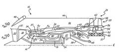
- FIG. 1is a schematic cross-sectional view of a variable cycle gas turbine engine having a peripheral propulsor operating in a high-speed mode.
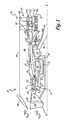
- FIG. 2is a schematic cross-sectional view of a variable cycle gas turbine engine having a peripheral propulsor operating in a low-speed mode.
- FIG. 1shows a schematic view of variable cycle gas turbine engine 10 of the present invention operating in a high-speed mode.
- Gas turbine engine 10includes a high pressure spool, which comprises high pressure compressor (HPC) 12 , high pressure turbine (HPT) 14 and high pressure shaft 16 ; a low pressure spool, which comprises fan 18 , low pressure turbine (LPT) 22 and low pressure shaft 24 ; and auxiliary power generator 26 , which comprises peripheral combustor 28 and peripheral propulsor 30 .
- HPChigh pressure compressor
- HPThigh pressure turbine
- LPTlow pressure turbine
- auxiliary power generator 26which comprises peripheral combustor 28 and peripheral propulsor 30 .
- engine 10is configured in a fan-high configuration, but in other embodiments fan-low-high configurations may be used.
- auxiliary power generator 26is shut down such that the high pressure spool and the low pressure spool operate with characteristics similar to that of a low bypass ratio turbofan engine.
- a duct system within engine 10operates to direct air from HPC 12 to auxiliary power generator 26 such that engine 10 operates with characteristics similar to that of a higher bypass ratio turbofan engine.
- the various components of engine 10 shown in FIGS. 1 and 2are not to scale and are shown larger or smaller to better illustrate the present invention.
- variable cycle gas turbine engine 10includes a main engine case 32 that includes inlet guide vanes (IGVs) 33 , into which a first stream of inlet air A 1A is received.
- Main engine case 32extends from forward of fan 18 to aft of LPT 22 , and provides a platform for auxiliary propulsor 30 .
- Flow diverter 34separates the first stream of inlet air A 1A into bypass air A 2 and core air A 3 .
- the specific volume of inlet air A 1A diverted to HPC 12 by flow diverter 34depends on selected design parameters and varies in different embodiments of the invention.
- Bypass air A 2is accelerated by fan 18 and directed into primary bypass duct 36 to produce a moderate pressure differential across fan 18 .
- the outer diameter surface of primary bypass duct 36is formed by engine case 32 , while the inner diameter surface of bypass duct 36 is formed by annular wall 37 . Annular wall 37 also forms the outer sealing structure for the high pressure spool and LPT 22 .
- Bypass air A 2is exhausted out of engine 10 to produce thrust at exhaust duct 38 .
- core air A 3is directed to high pressure compressor 12 whereby it is further compressed to produce supercharged air that is directed to combustor 40 .
- the supercharged core airis mixed with fuel and burned within combustor 40 to produce high energy gases for rotating HPT 14 and LPT 22 .
- HPT 14 and LPT 22are drivingly connected to HPC 12 and fan 18 through shafts 16 and 24 , respectively, such that the combustion process can be sustained with pressurized air generated by Fan 18 and HPC 12 .
- a small amount of bleed air A 4is siphoned from supercharged core air at HPC 12 .
- Exhaust flows A 5 , A 2 and A 4may be optimally mixed (combined) via fixed or variable devices balancing static pressure prior to exit, through a common nozzle 100 , or exhausted separately via independent nozzle streams.
- the first stage blade of HPC 12includes shrouded tips 41 or a core driven fan stage (CDFS) that pulls a small amount of air from core air A 3 .
- CDFScore driven fan stage
- bleed air A 4is routed to bleed duct 42 , which is positioned within bypass duct 36 , where it is exhausted from engine 10 along with bypass air A 2 and exhaust gas A 5 at duct 38 to produce thrust.
- bleed air A 4increases the net fan pressure ratio when combined with fan 18 .
- the volume of core air A 3 discharged into bleed duct 42 by the tip shroud of HPC 12depends on selected design parameters and varies in different embodiments of the invention.
- Bleed duct 42includes variable discharge portion 43 that can be configured to route bleed air A 4 to peripheral combustor 28 for low-speed mode operation.
- Engine 10also includes peripheral case 44 that circumscribes main engine case 32 to form peripheral duct 46 .
- Peripheral combustor 28 and peripheral propulsor 30are positioned within peripheral duct 46 between peripheral case 44 and engine case 32 .
- Peripheral duct 46is configured to receive a second stream of inlet air A 1B via a secondary or auxiliary inlet for acceleration by peripheral propulsor 30 to produce thrust.
- peripheral duct 46is closed off by door 48 such that engine 10 is operable similar to a low bypass turbofan, as described above.
- engine 10is operated in the high-speed mode to produce a large pressure ratio across fan 18 , e.g.
- FIG. 2shows a schematic view of variable cycle gas turbine engine 10 of FIG. 1 operating in a low-speed mode such that airflows are directed to auxiliary propulsor 26 .
- bleed air A 4is directed to peripheral combustor 28
- a second stream of inlet air A 1Bis directed to peripheral propulsor 30 .
- Peripheral propulsor 30includes bearings 50 , rotor 52 , turbine blades 54 , shroud 56 and fan blades 58 .
- door 48is opened, such as through an actuator controlled by a Full Authority Digital Engine Control (FADEC), to direct a second stream of inlet air A 1B to peripheral duct 46 , which increases the total volume of inlet air (A 1A and A 1B ) provided to engine 10 .
- FADECFull Authority Digital Engine Control
- the specific increase in volume of inlet air (A 1A and A 1B ) by the opening of door 48depends on selected design parameters and varies in different embodiments of the invention. However, in other embodiments, door 48 can be intermittently adjusted to control the amount of inlet air A 1B that enters peripheral duct 46 .
- variable duct portion 43 of bleed duct 42comprises any suitable means for redirecting bleed air A 4 from bleed duct 42 .
- bleed duct 42comprises a plurality of cylindrical ducts that extend from behind shroud tips 41 of the blades of HPC 12 and into bypass duct 36 . As such, bypass air A 2 is able to flow within bypass duct 36 between the plurality of cylindrical ducts comprising bleed duct 42 .
- variable duct portion 43comprises a hinged duct that is actuated between two positions by, for example, a hydraulic actuator positioned on the outside of bleed duct 42 .
- a hydraulic actuatorpositioned on the outside of bleed duct 42 .
- variable duct portion 43In a first position, shown in FIG. 1 , variable duct portion 43 is rotated inward such that bleed air A 4 discharges into bypass duct 36 and the effective pressure ratio across fan 18 is increased.
- variable duct portion 43is rotated outward to extend to an opening in engine case 32 , which opens to an inlet in peripheral combustor 28 .
- the pressure ratio across fan 18is decreased, as the high pressure bleed air A 4 is no longer exhausted with bypass air A 2 , freeing bleed air A 4 to supply a combustion process within peripheral combustor 28 .
- the total amount of inlet air A 1A that bypasses core combustor 40is increased as door 48 is opened to receive inlet air A 1B .
- Peripheral combustor 28 and propulsor 30are positioned within peripheral duct 46 to receive bleed air A 4 and inlet air A 1B , respectively, to produce thrust.
- gas turbine engine 10is operating at less than full throttle to sustain the combustion process inside main combustor 40 with core air A 3 .
- HPC 12has capacity to supply bleed air A 4 to peripheral combustor 28 .
- Combustor 28is positioned at a radially inner portion of peripheral duct 46 .
- combustor 28is positioned by a portion of engine case 32 that bends in toward the center of engine 10 such that variable duct portion 43 of bleed duct 42 can be extended axially to join with combustor 28 .
- Partition 60extends from engine case 32 to wall-off combustor 28 from peripheral duct 44 and inlet air A 1B .
- combustor 28comprises an annular combustor configured to receive bleed air A 4 from the individual cylindrical ducts comprising bleed duct 42 .
- An annular combustor with such a large diameter suitable for use in the present inventionis described in U.S. Pat. App. No. 2007/0022738A1 by Norris et al. and assigned to United Technologies Corporation.
- Peripheral propulsor 30is positioned on engine case 32 downstream of combustor 28 .
- Bearings 50are provided on engine case 32 such that rotor 52 is able to freely rotate about engine case 32 . Any bearings having a high DN number (bearing diameter multiplied by the maximum bearing speed [RPM]) are suitable for use in the present invention.
- bearings 50comprise air bearings as are know in the art having a suitably large DN number.
- Rotor 52comprises an annular drum upon which turbine blades 54 and fan blades 58 are mounted.
- fan blades 58are integrally formed at the radially distal end of turbine blades 54 .
- fan blades 58 and turbine blades 54form a single airfoil blade, with the lower portion configured to receive bleed air A 4 , and an upper portion configured to push inlet air A 1B .
- Any suitable dual-structure airfoil blade as is known in the artmay be used with the present invention, such as the FLADE airfoil blades described in the Johnson '475 patent.
- Shroud 56separates turbine blades 54 from fan blades 58 and separates airflow within peripheral duct 46 .
- Peripheral propulsor 30is positioned within peripheral case 44 such that turbine blades 54 align with combustor 28 , shroud 56 aligns with partition 60 , and fan blades 58 align with peripheral duct 46 .
- peripheral propulsor 30is split into two-stage, counter-rotating turbine blades and fan blades. In other embodiments, however, synchronous rotating or single-stage blades can be used.
- a combustion processis executed in peripheral combustor 28 using bleed air A 4 and a fuel to produce exhaust gas A 6 .
- peripheral combustor 28is provided with fuel from the same source that supplies main combustor 40 using any conventional fuel delivery system.
- Exhaust gas A 6is expanded through peripheral propulsor 30 such that it impinges upon turbine blades 54 to impart rotation of rotor 52 about engine case 32 .
- the high pressure bleed air A 4 that passes through shrouded tips 41 of HPC 12is expanded such that a low pressure ratio across turbine blades 54 results.
- Shroud 56 and rotor 52prevent exhaust gas A 6 from leaking past turbine blades 54 , and in one embodiment include overlapping segments to provide a sealing path between the counter-rotating segments.
- Fan blades 58are thus driven by turbine blades 54 and perform work on the second stream of inlet air A 1B within peripheral duct 46 to increase the pressure ratio across auxiliary propulsor 30 . In one embodiment, a pressure ratio of about 2.0 is produced across fan blades 58 .
- variable cycle gas turbine engineis operable similar to a high bypass turbofan engine. Specifically, a portion of the first stream of inlet air A 1A , bypass air A 2 , is used to sustain the combustion process in main combustor 40 , while another portion, bleed air A 4 , is used to produce thrust with fan 18 . Inlet air A 1B is also accelerated to produce thrust by using supercharged bleed air A 4 diverted from HPC 12 .
- Inlet air A 1B and bypass air A 2comprise a majority of the inlet air routed into engine 10 and are accelerated to low velocities.
- engine 10imparts a small increase in momentum to large quantity of air, which bypasses main combustor 40 , to produce thrust.
- engine 10is configured to achieve better propulsive efficiencies at low, rather than high, speeds.
Landscapes
- Engineering & Computer Science (AREA)
- Chemical & Material Sciences (AREA)
- Combustion & Propulsion (AREA)
- Mechanical Engineering (AREA)
- General Engineering & Computer Science (AREA)
- Structures Of Non-Positive Displacement Pumps (AREA)
- Control Of Turbines (AREA)
Abstract
Description
Claims (18)
Priority Applications (1)
| Application Number | Priority Date | Filing Date | Title |
|---|---|---|---|
| US12/072,353US8127528B2 (en) | 2008-02-26 | 2008-02-26 | Auxiliary propulsor for a variable cycle gas turbine engine |
Applications Claiming Priority (1)
| Application Number | Priority Date | Filing Date | Title |
|---|---|---|---|
| US12/072,353US8127528B2 (en) | 2008-02-26 | 2008-02-26 | Auxiliary propulsor for a variable cycle gas turbine engine |
Publications (2)
| Publication Number | Publication Date |
|---|---|
| US20090211221A1 US20090211221A1 (en) | 2009-08-27 |
| US8127528B2true US8127528B2 (en) | 2012-03-06 |
Family
ID=40996964
Family Applications (1)
| Application Number | Title | Priority Date | Filing Date |
|---|---|---|---|
| US12/072,353Active2031-07-13US8127528B2 (en) | 2008-02-26 | 2008-02-26 | Auxiliary propulsor for a variable cycle gas turbine engine |
Country Status (1)
| Country | Link |
|---|---|
| US (1) | US8127528B2 (en) |
Cited By (18)
| Publication number | Priority date | Publication date | Assignee | Title |
|---|---|---|---|---|
| US20110138814A1 (en)* | 2009-12-11 | 2011-06-16 | Rupp George D | Aircraft Engine Airflow Modulation Apparatus and Method for Engine Bay Cooling and Cycle Flow Matching |
| US20130000273A1 (en)* | 2011-06-29 | 2013-01-03 | United Technologies Corporation | Gas-driven propulsor with tip turbine fan |
| US9116051B2 (en) | 2013-03-07 | 2015-08-25 | United Technologies Corporation | Actively cooled gas turbine sensor probe housing |
| US9140212B2 (en) | 2012-06-25 | 2015-09-22 | United Technologies Corporation | Gas turbine engine with reverse-flow core having a bypass flow splitter |
| US9157366B2 (en) | 2012-05-30 | 2015-10-13 | United Technologies Corporation | Adaptive fan with cold turbine |
| US9488101B2 (en) | 2013-03-14 | 2016-11-08 | United Technologies Corporation | Adaptive fan reverse core geared turbofan engine with separate cold turbine |
| US9850822B2 (en) | 2013-03-15 | 2017-12-26 | United Technologies Corporation | Shroudless adaptive fan with free turbine |
| US10072510B2 (en) | 2014-11-21 | 2018-09-11 | General Electric Company | Variable pitch fan for gas turbine engine and method of assembling the same |
| US10563516B2 (en) | 2016-07-06 | 2020-02-18 | General Electric Company | Turbine engine and method of assembling |
| US10683806B2 (en)* | 2017-01-05 | 2020-06-16 | General Electric Company | Protected core inlet with reduced capture area |
| US10787996B2 (en)* | 2013-03-15 | 2020-09-29 | Raytheon Technologies Corporation | Gas turbine engine with stream diverter |
| US10822991B2 (en) | 2016-08-01 | 2020-11-03 | General Electric Company | Method and apparatus for active clearance control on gas turbine engines |
| US20200386407A1 (en)* | 2019-06-06 | 2020-12-10 | Pratt & Whitney Canada Corp. | Aircraft engine and method of operation thereof |
| US11105269B2 (en) | 2017-05-12 | 2021-08-31 | General Electric Company | Method of control of three spool gas turbine engine |
| US11428160B2 (en) | 2020-12-31 | 2022-08-30 | General Electric Company | Gas turbine engine with interdigitated turbine and gear assembly |
| US11674435B2 (en) | 2021-06-29 | 2023-06-13 | General Electric Company | Levered counterweight feathering system |
| US11795964B2 (en) | 2021-07-16 | 2023-10-24 | General Electric Company | Levered counterweight feathering system |
| WO2025046013A1 (en)* | 2023-08-31 | 2025-03-06 | Reaction Engines Limited | Engines |
Families Citing this family (15)
| Publication number | Priority date | Publication date | Assignee | Title |
|---|---|---|---|---|
| US8256202B1 (en)* | 2008-11-25 | 2012-09-04 | Florida Turbine Technologies, Inc. | High bypass turbofan |
| US20110146228A1 (en)* | 2009-12-21 | 2011-06-23 | John Lewis Baughman | Power extraction system |
| US20110146289A1 (en)* | 2009-12-21 | 2011-06-23 | John Lewis Baughman | Power extraction method |
| FR2955085B1 (en)* | 2010-01-08 | 2011-12-23 | Snecma | SYSTEM FOR CONTRAROTATIVE PROPELLERS FOR AIRCRAFT TURBOMACHINE |
| US8667773B2 (en) | 2011-06-28 | 2014-03-11 | United Technologies Corporation | Counter-rotating turbomachinery |
| US9188083B2 (en) | 2011-10-28 | 2015-11-17 | United Technologies Corporation | Gas turbine engine with auxiliary fan |
| US9017037B2 (en) | 2012-01-24 | 2015-04-28 | United Technologies Corporation | Rotor with flattened exit pressure profile |
| US8365514B1 (en) | 2012-02-27 | 2013-02-05 | United Technologies Corporation | Hybrid turbofan engine |
| US10563592B2 (en) | 2012-12-14 | 2020-02-18 | United Technologies Corporation | Turbo compressor for bleed air |
| EP2971535A4 (en) | 2013-03-15 | 2017-02-15 | United Technologies Corporation | Geared turbofan engine having a reduced number of fan blades and improved acoustics |
| US9869190B2 (en) | 2014-05-30 | 2018-01-16 | General Electric Company | Variable-pitch rotor with remote counterweights |
| US10100653B2 (en) | 2015-10-08 | 2018-10-16 | General Electric Company | Variable pitch fan blade retention system |
| US20170314509A1 (en)* | 2016-04-27 | 2017-11-02 | General Electric Company | Turbofan assembly and method of assembling |
| WO2024096946A2 (en) | 2022-08-11 | 2024-05-10 | Next Gen Compression Llc | Variable geometry supersonic compressor |
| CN116085142B (en)* | 2023-04-11 | 2023-05-30 | 北京航空航天大学 | Novel overall structure of interstage combustion variable cycle engine |
Citations (24)
| Publication number | Priority date | Publication date | Assignee | Title |
|---|---|---|---|---|
| US3693354A (en)* | 1971-01-22 | 1972-09-26 | Gen Electric | Aircraft engine fan duct burner system |
| US3811791A (en) | 1971-08-12 | 1974-05-21 | R Cotton | Thrust augmenting device for jet aircraft |
| US4043121A (en) | 1975-01-02 | 1977-08-23 | General Electric Company | Two-spool variable cycle engine |
| US4054030A (en)* | 1976-04-29 | 1977-10-18 | General Motors Corporation | Variable cycle gas turbine engine |
| EP0076192A1 (en) | 1981-09-25 | 1983-04-06 | Societe Nationale D'etude Et De Construction De Moteurs D'aviation, "S.N.E.C.M.A." | Jet engine, especially for a supersonic aircraft |
| GB2129502A (en) | 1982-11-01 | 1984-05-16 | Gen Electric | Counter rotation power turbine |
| GB2174761A (en) | 1985-05-03 | 1986-11-12 | Gen Electric | High mach number unducted fan engine |
| US4826403A (en) | 1986-07-02 | 1989-05-02 | Rolls-Royce Plc | Turbine |
| US4927329A (en) | 1988-10-21 | 1990-05-22 | General Electric Company | Aircraft engine unducted fan blade pitch control system |
| US4934825A (en) | 1987-12-22 | 1990-06-19 | United Technologies Corporation | Propeller phase control apparatus |
| US5079916A (en) | 1982-11-01 | 1992-01-14 | General Electric Company | Counter rotation power turbine |
| US5311736A (en) | 1991-12-24 | 1994-05-17 | Societe Nationale D'etude Et De Construction De Moteurs D'aviation "S.N.E.C.M.A." | Variable cycle propulsion engine for supersonic aircraft |
| US5402638A (en) | 1993-10-04 | 1995-04-04 | General Electric Company | Spillage drag reducing flade engine |
| US5794432A (en) | 1996-08-27 | 1998-08-18 | Diversitech, Inc. | Variable pressure and variable air flow turbofan engines |
| US5806303A (en) | 1996-03-29 | 1998-09-15 | General Electric Company | Turbofan engine with a core driven supercharged bypass duct and fixed geometry nozzle |
| US5809772A (en) | 1996-03-29 | 1998-09-22 | General Electric Company | Turbofan engine with a core driven supercharged bypass duct |
| US6901739B2 (en) | 2003-10-07 | 2005-06-07 | General Electric Company | Gas turbine engine with variable pressure ratio fan system |
| US6966174B2 (en) | 2002-04-15 | 2005-11-22 | Paul Marius A | Integrated bypass turbojet engines for air craft and other vehicles |
| US6968674B2 (en)* | 2003-01-28 | 2005-11-29 | General Electric Company | Methods and apparatus for operating gas turbine engines |
| WO2006059980A2 (en) | 2004-12-01 | 2006-06-08 | United Technologies Corporation | Diffuser aspiration for a tip turbine engine |
| WO2006060003A2 (en) | 2004-12-01 | 2006-06-08 | United Technologies Corporation | Fan blade with integral diffuser section and tip turbine blade section for a tip turbine engine |
| US20070022738A1 (en) | 2005-07-27 | 2007-02-01 | United Technologies Corporation | Reinforcement rings for a tip turbine engine fan-turbine rotor assembly |
| US7216475B2 (en)* | 2003-11-21 | 2007-05-15 | General Electric Company | Aft FLADE engine |
| US7246484B2 (en) | 2003-08-25 | 2007-07-24 | General Electric Company | FLADE gas turbine engine with counter-rotatable fans |
- 2008
- 2008-02-26USUS12/072,353patent/US8127528B2/enactiveActive
Patent Citations (24)
| Publication number | Priority date | Publication date | Assignee | Title |
|---|---|---|---|---|
| US3693354A (en)* | 1971-01-22 | 1972-09-26 | Gen Electric | Aircraft engine fan duct burner system |
| US3811791A (en) | 1971-08-12 | 1974-05-21 | R Cotton | Thrust augmenting device for jet aircraft |
| US4043121A (en) | 1975-01-02 | 1977-08-23 | General Electric Company | Two-spool variable cycle engine |
| US4054030A (en)* | 1976-04-29 | 1977-10-18 | General Motors Corporation | Variable cycle gas turbine engine |
| EP0076192A1 (en) | 1981-09-25 | 1983-04-06 | Societe Nationale D'etude Et De Construction De Moteurs D'aviation, "S.N.E.C.M.A." | Jet engine, especially for a supersonic aircraft |
| GB2129502A (en) | 1982-11-01 | 1984-05-16 | Gen Electric | Counter rotation power turbine |
| US5079916A (en) | 1982-11-01 | 1992-01-14 | General Electric Company | Counter rotation power turbine |
| GB2174761A (en) | 1985-05-03 | 1986-11-12 | Gen Electric | High mach number unducted fan engine |
| US4826403A (en) | 1986-07-02 | 1989-05-02 | Rolls-Royce Plc | Turbine |
| US4934825A (en) | 1987-12-22 | 1990-06-19 | United Technologies Corporation | Propeller phase control apparatus |
| US4927329A (en) | 1988-10-21 | 1990-05-22 | General Electric Company | Aircraft engine unducted fan blade pitch control system |
| US5311736A (en) | 1991-12-24 | 1994-05-17 | Societe Nationale D'etude Et De Construction De Moteurs D'aviation "S.N.E.C.M.A." | Variable cycle propulsion engine for supersonic aircraft |
| US5402638A (en) | 1993-10-04 | 1995-04-04 | General Electric Company | Spillage drag reducing flade engine |
| US5806303A (en) | 1996-03-29 | 1998-09-15 | General Electric Company | Turbofan engine with a core driven supercharged bypass duct and fixed geometry nozzle |
| US5809772A (en) | 1996-03-29 | 1998-09-22 | General Electric Company | Turbofan engine with a core driven supercharged bypass duct |
| US5794432A (en) | 1996-08-27 | 1998-08-18 | Diversitech, Inc. | Variable pressure and variable air flow turbofan engines |
| US6966174B2 (en) | 2002-04-15 | 2005-11-22 | Paul Marius A | Integrated bypass turbojet engines for air craft and other vehicles |
| US6968674B2 (en)* | 2003-01-28 | 2005-11-29 | General Electric Company | Methods and apparatus for operating gas turbine engines |
| US7246484B2 (en) | 2003-08-25 | 2007-07-24 | General Electric Company | FLADE gas turbine engine with counter-rotatable fans |
| US6901739B2 (en) | 2003-10-07 | 2005-06-07 | General Electric Company | Gas turbine engine with variable pressure ratio fan system |
| US7216475B2 (en)* | 2003-11-21 | 2007-05-15 | General Electric Company | Aft FLADE engine |
| WO2006059980A2 (en) | 2004-12-01 | 2006-06-08 | United Technologies Corporation | Diffuser aspiration for a tip turbine engine |
| WO2006060003A2 (en) | 2004-12-01 | 2006-06-08 | United Technologies Corporation | Fan blade with integral diffuser section and tip turbine blade section for a tip turbine engine |
| US20070022738A1 (en) | 2005-07-27 | 2007-02-01 | United Technologies Corporation | Reinforcement rings for a tip turbine engine fan-turbine rotor assembly |
Cited By (22)
| Publication number | Priority date | Publication date | Assignee | Title |
|---|---|---|---|---|
| US20110138814A1 (en)* | 2009-12-11 | 2011-06-16 | Rupp George D | Aircraft Engine Airflow Modulation Apparatus and Method for Engine Bay Cooling and Cycle Flow Matching |
| US9353684B2 (en)* | 2009-12-11 | 2016-05-31 | Northrop Grumman Systems Corporation | Aircraft engine airflow modulation apparatus and method for engine bay cooling and cycle flow matching |
| US20130000273A1 (en)* | 2011-06-29 | 2013-01-03 | United Technologies Corporation | Gas-driven propulsor with tip turbine fan |
| US8943792B2 (en)* | 2011-06-29 | 2015-02-03 | United Technologies Corporation | Gas-driven propulsor with tip turbine fan |
| US9157366B2 (en) | 2012-05-30 | 2015-10-13 | United Technologies Corporation | Adaptive fan with cold turbine |
| US9140212B2 (en) | 2012-06-25 | 2015-09-22 | United Technologies Corporation | Gas turbine engine with reverse-flow core having a bypass flow splitter |
| US9116051B2 (en) | 2013-03-07 | 2015-08-25 | United Technologies Corporation | Actively cooled gas turbine sensor probe housing |
| US10533493B2 (en) | 2013-03-14 | 2020-01-14 | United Technologies Corporation | Adaptive fan reverse core geared turbofan engine with separate cold turbine |
| US9488101B2 (en) | 2013-03-14 | 2016-11-08 | United Technologies Corporation | Adaptive fan reverse core geared turbofan engine with separate cold turbine |
| US10787996B2 (en)* | 2013-03-15 | 2020-09-29 | Raytheon Technologies Corporation | Gas turbine engine with stream diverter |
| US9850822B2 (en) | 2013-03-15 | 2017-12-26 | United Technologies Corporation | Shroudless adaptive fan with free turbine |
| US10072510B2 (en) | 2014-11-21 | 2018-09-11 | General Electric Company | Variable pitch fan for gas turbine engine and method of assembling the same |
| US10563516B2 (en) | 2016-07-06 | 2020-02-18 | General Electric Company | Turbine engine and method of assembling |
| US10822991B2 (en) | 2016-08-01 | 2020-11-03 | General Electric Company | Method and apparatus for active clearance control on gas turbine engines |
| US10683806B2 (en)* | 2017-01-05 | 2020-06-16 | General Electric Company | Protected core inlet with reduced capture area |
| US11105269B2 (en) | 2017-05-12 | 2021-08-31 | General Electric Company | Method of control of three spool gas turbine engine |
| US20200386407A1 (en)* | 2019-06-06 | 2020-12-10 | Pratt & Whitney Canada Corp. | Aircraft engine and method of operation thereof |
| US11428160B2 (en) | 2020-12-31 | 2022-08-30 | General Electric Company | Gas turbine engine with interdigitated turbine and gear assembly |
| US11674435B2 (en) | 2021-06-29 | 2023-06-13 | General Electric Company | Levered counterweight feathering system |
| US12180886B2 (en) | 2021-06-29 | 2024-12-31 | General Electric Company | Levered counterweight feathering system |
| US11795964B2 (en) | 2021-07-16 | 2023-10-24 | General Electric Company | Levered counterweight feathering system |
| WO2025046013A1 (en)* | 2023-08-31 | 2025-03-06 | Reaction Engines Limited | Engines |
Also Published As
| Publication number | Publication date |
|---|---|
| US20090211221A1 (en) | 2009-08-27 |
Similar Documents
| Publication | Publication Date | Title |
|---|---|---|
| US8127528B2 (en) | Auxiliary propulsor for a variable cycle gas turbine engine | |
| US8082727B2 (en) | Rear propulsor for a variable cycle gas turbine engine | |
| JP5121440B2 (en) | Convertible gas turbine engine | |
| CN101021181B (en) | Double bypass turbofan | |
| US9016041B2 (en) | Variable-cycle gas turbine engine with front and aft FLADE stages | |
| US7765789B2 (en) | Apparatus and method for assembling gas turbine engines | |
| US8777554B2 (en) | Intermediate fan stage | |
| US10385871B2 (en) | Method and system for compressor vane leading edge auxiliary vanes | |
| US20110167784A1 (en) | Method of operating a convertible fan engine | |
| US20110167792A1 (en) | Adaptive engine | |
| US20130205752A1 (en) | Gas turbine engine with separate core and propulsion unit | |
| US3956887A (en) | Gas turbine engines | |
| WO2015012920A2 (en) | Secondary nozzle for jet engine | |
| US20140205438A1 (en) | Relationship between fan and primary exhaust stream velocities in a geared gas turbine engine | |
| EP2820278A1 (en) | Hybrid turbofan engine | |
| US20110150627A1 (en) | Method of operating a fan system | |
| US11286856B2 (en) | Diversion of fan air to provide cooling air for gas turbine engine | |
| EP2336522B1 (en) | Intermediate fan stage | |
| CA2724610C (en) | Intermediate fan stage | |
| JP2011127598A (en) | Power extraction system |
Legal Events
| Date | Code | Title | Description |
|---|---|---|---|
| AS | Assignment | Owner name:UNITED TECHNOLOGIES CORPORATION, CONNECTICUT Free format text:ASSIGNMENT OF ASSIGNORS INTEREST;ASSIGNOR:ROBERGE, GARY D.;REEL/FRAME:020612/0196 Effective date:20080225 | |
| STCF | Information on status: patent grant | Free format text:PATENTED CASE | |
| FPAY | Fee payment | Year of fee payment:4 | |
| MAFP | Maintenance fee payment | Free format text:PAYMENT OF MAINTENANCE FEE, 8TH YEAR, LARGE ENTITY (ORIGINAL EVENT CODE: M1552); ENTITY STATUS OF PATENT OWNER: LARGE ENTITY Year of fee payment:8 | |
| AS | Assignment | Owner name:RAYTHEON TECHNOLOGIES CORPORATION, MASSACHUSETTS Free format text:CHANGE OF NAME;ASSIGNOR:UNITED TECHNOLOGIES CORPORATION;REEL/FRAME:054062/0001 Effective date:20200403 | |
| AS | Assignment | Owner name:RAYTHEON TECHNOLOGIES CORPORATION, CONNECTICUT Free format text:CORRECTIVE ASSIGNMENT TO CORRECT THE AND REMOVE PATENT APPLICATION NUMBER 11886281 AND ADD PATENT APPLICATION NUMBER 14846874. TO CORRECT THE RECEIVING PARTY ADDRESS PREVIOUSLY RECORDED AT REEL: 054062 FRAME: 0001. ASSIGNOR(S) HEREBY CONFIRMS THE CHANGE OF ADDRESS;ASSIGNOR:UNITED TECHNOLOGIES CORPORATION;REEL/FRAME:055659/0001 Effective date:20200403 | |
| AS | Assignment | Owner name:RTX CORPORATION, CONNECTICUT Free format text:CHANGE OF NAME;ASSIGNOR:RAYTHEON TECHNOLOGIES CORPORATION;REEL/FRAME:064714/0001 Effective date:20230714 | |
| MAFP | Maintenance fee payment | Free format text:PAYMENT OF MAINTENANCE FEE, 12TH YEAR, LARGE ENTITY (ORIGINAL EVENT CODE: M1553); ENTITY STATUS OF PATENT OWNER: LARGE ENTITY Year of fee payment:12 |