US8127182B2 - Storage utilization to improve reliability using impending failure triggers - Google Patents
Storage utilization to improve reliability using impending failure triggersDownload PDFInfo
- Publication number
- US8127182B2 US8127182B2US12/211,188US21118808AUS8127182B2US 8127182 B2US8127182 B2US 8127182B2US 21118808 AUS21118808 AUS 21118808AUS 8127182 B2US8127182 B2US 8127182B2
- Authority
- US
- United States
- Prior art keywords
- storage device
- data
- indicator
- drive
- copying
- Prior art date
- Legal status (The legal status is an assumption and is not a legal conclusion. Google has not performed a legal analysis and makes no representation as to the accuracy of the status listed.)
- Expired - Fee Related, expires
Links
Images


Classifications
- G—PHYSICS
- G06—COMPUTING OR CALCULATING; COUNTING
- G06F—ELECTRIC DIGITAL DATA PROCESSING
- G06F11/00—Error detection; Error correction; Monitoring
- G06F11/07—Responding to the occurrence of a fault, e.g. fault tolerance
- G06F11/16—Error detection or correction of the data by redundancy in hardware
- G06F11/20—Error detection or correction of the data by redundancy in hardware using active fault-masking, e.g. by switching out faulty elements or by switching in spare elements
- G06F11/2053—Error detection or correction of the data by redundancy in hardware using active fault-masking, e.g. by switching out faulty elements or by switching in spare elements where persistent mass storage functionality or persistent mass storage control functionality is redundant
- G06F11/2094—Redundant storage or storage space
- G—PHYSICS
- G06—COMPUTING OR CALCULATING; COUNTING
- G06F—ELECTRIC DIGITAL DATA PROCESSING
- G06F11/00—Error detection; Error correction; Monitoring
- G06F11/07—Responding to the occurrence of a fault, e.g. fault tolerance
- G06F11/16—Error detection or correction of the data by redundancy in hardware
- G06F11/20—Error detection or correction of the data by redundancy in hardware using active fault-masking, e.g. by switching out faulty elements or by switching in spare elements
- G06F11/2097—Error detection or correction of the data by redundancy in hardware using active fault-masking, e.g. by switching out faulty elements or by switching in spare elements maintaining the standby controller/processing unit updated
Definitions
- Mass storage systemscontinue to provide increased storage capacities to satisfy user demands.
- Photo and movie storage, and photo and movie sharingare examples of applications that fuel the growth in demand for larger and larger storage systems.
- arrays of multiple inexpensive disksmay be configured in ways that provide redundancy and error recovery without any loss of data. These arrays may also be configured to increase read and write performance by allowing data to be read or written simultaneously to multiple disk drives. These arrays may also be configured to allow “hot-swapping” which allows a failed disk to be replaced without interrupting the storage services of the array. Whether or not any redundancy is provided, these arrays are commonly referred to as redundant arrays of independent disks (or more commonly by the acronym RAID).
- RAIDredundant arrays of independent disks
- RAID storage systemstypically utilize a controller that shields the user or host system from the details of managing the storage array.
- the controllermakes the storage array appear as one or more disk drives (or volumes). This is accomplished in spite of the fact that the data (or redundant data) for a particular volume may be spread across multiple disk drives.
- An embodiment of the inventionmay therefore comprise a method of improving storage reliability, comprising receiving an indicator of an impending failure of a first storage device in a RAID group; in response to said indicator, ceasing writing data to said first storage device; writing, to a memory device, a first block of data directed to be written on said first storage device; copying data stored on said first storage device to a second storage device; copying said first block of data from said memory device to said second storage device; operating said RAID group with said second storage device functioning in place of said first storage device; and, reading data from said second storage device.
- An embodiment of the inventionmay therefore further comprise a method of improving storage reliability, comprising receiving an indicator of an impending failure of a first storage device in a RAID group; in response to said indicator, ceasing writing data to said first storage device; writing, to a memory device, a first block of data directed to be written on said first storage device; copying data stored on said first storage device to a first portion of a second storage device that is unused, wherein a second portion of said second storage device is part of a second RAID group; copying said first block of data from said memory device to said first portion of said second storage device; operating said RAID group with said first portion of said second storage device functioning in place of at least a portion of said first storage device; and, reading data from said first portion of said second storage device.
- FIG. 1is a block diagram illustrating a storage system.
- FIG. 2is a block diagram illustrating a storage system.
- FIG. 3is a flowchart illustrating a method of improving storage reliability.
- FIG. 4is a flowchart illustrating a method of improving storage reliability.
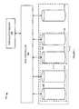
- FIG. 1is a block diagram illustrating a storage system.
- storage system 100comprises drive group 110 , RAID controller 120 , and nonvolatile memory 130 .
- Drive group 110is comprised of a plurality of RAID groups illustrated by RAID group 140 and RAID group 141 .
- Drive group 110also includes spare drive 115 .
- RAID group 140is comprised of drive 112 and failing drive 111 .
- RAID group 141is comprised of drive 113 and drive 114 .
- Nonvolatile memory 130is preferably comprised of solid state nonvolatile memories.
- nonvolatile memory 130may be a solid state disk drive.
- nonvolatile memory 130may communicate with RAID controller 120 using commands and procedures that are similar to those RAID controller 120 uses to communicate with drives 111 - 114 .
- RAID controller 120may receive an indication of an impending failure of failing drive 111 .
- This indicationmay be supplied to RAID controller 120 by failing drive 111 using Self-Monitoring, Analysis, and Reporting Technology (SMART).
- SMARTis a monitoring system for computer hard drives to detect and report on various indicators of reliability to provide indications of impending failures. SMART is further described in “Information technology—AT Attachment 8—ATA/ATAPI Command Set (ATA8-ACS), working draft revision 3f” available from www.t13.org.
- failing drive 111may provide RAID controller 120 with an indication that a failing drive 111 is in a condition that indicates an impending failure of failing drive 111 .
- RAID controller 120takes action to make a copy of the data on failing drive 111 .
- RAID controller 120in response to receiving an indication of an impending failure, checks configuration information for drive group 110 to determine if there is a spare drive 115 .
- spare drive 115may be a drive configured as a hot spare drive.
- spare drive 115may be a drive that has not been assigned to a RAID group 140 - 141 (i.e., an “unassigned” drive).
- RAID controller 120may then copy the data on failing drive 111 to spare drive 115 . Before copying, RAID controller 120 may first determine if spare drive 115 is of greater than or equivalent capacity of failing drive 111 .
- RAID controller 120may stop further writes to failing drive 111 . These writes may be re-directed to nonvolatile memory 130 .
- Nonvolatile memory 130may act as a write cache for writes of blocks of data that are directed to failing drive 111 .
- Nonvolatile memory 130may act as this write cache while data is being copied from failing drive 111 to spare drive 115 .
- RAID controller 120may copy the written blocks of data cached in nonvolatile memory 130 to spare drive 115 . In other words, RAID controller may flush the cached writes stored in nonvolatile memory 130 to spare drive 115 .
- RAID controller 120may then operate RAID group 140 with spare drive 115 functioning in place of failing drive 111 .
- RAID controller 120may not copy the data on failing drive 111 directly from failing drive 111 . Instead, RAID controller may use one or more non-failing drives (such as drive 112 ) of RAID group 140 to reconstruct the data on failing drive 111 . This reconstructed image of the data on failing drive 111 may be copied to spare drive 115 . The data stored on failing drive 111 may be reconstructed using one or more RAID techniques. Thus, if failing drive 111 fails during the copying of data to spare drive 115 , the copying operation is unaffected.
- FIG. 2is a block diagram illustrating a storage system.
- storage system 200comprises drive group 210 , RAID controller 220 , and nonvolatile memory 230 .
- Drive group 210is comprised of a plurality of RAID groups illustrated by RAID group 240 and RAID group 241 .
- RAID group 240is comprised of drive 212 and failing drive 211 .
- RAID group 241is comprised of drive 213 and drive 214 .
- Drive 212is shown partitioned into drive portion 2120 and unused drive portion 2121 .
- Drive 213is shown partitioned into drive portion 2130 and unused drive portion 2131 .
- Nonvolatile memory 230is preferably comprised of solid state nonvolatile memories.
- nonvolatile memory 230may be a solid state disk drive.
- nonvolatile memory 230may communicate with RAID controller 220 using commands and procedures that are similar to those RAID controller 220 uses to communicate with drives 211 - 214 .
- RAID controller 220may receive an indication of an impending failure of failing drive 211 . This indication may be supplied to RAID controller 220 by failing drive 211 using SMART. In an embodiment, failing drive 211 may provide RAID controller 220 with an indication that a failing drive 211 is in a condition that indicates an impending failure of failing drive 211 . In an embodiment, when failing drive 211 provides RAID controller 220 with an indication of an impending failure, RAID controller 220 takes action to make a copy of the data on failing drive 211 .
- RAID controller 220in response to receiving an indication of an impending failure, checks configuration information for drive group 210 to determine if there is enough space on unused drive portions to receive a copy of the data on failing drive 211 .
- an unused drive portionmay be an entire drive (such as an unallocated or hot swap drive) that has a smaller capacity than failing drive 211 .
- RAID controller 220determines if there is enough space on unused drive portions that are on drives in RAID groups that are not part of the RAID group of failing drive 211 . In other words, RAID controller 220 determines if there is enough space on unused drive portion 2131 (and other unused drive portions not part of RAID group 240 ) to receive a copy of the data on failing drive 211 . In FIG. 2 , this means that unused drive portion 2121 is not counted (or later used) for the purpose of receiving a copy of the data on failing drive 211 . RAID controller 220 may then copy the data on failing drive 211 to the unused drive portions. In FIG. 2 , these unused drive portions include unused drive portion 2131 .
- RAID controller 220may stop further writes to failing drive 211 . These writes may be re-directed to nonvolatile memory 230 .
- Nonvolatile memory 230may act as a cache for writes of blocks of data that are directed to failing drive 211 . Nonvolatile memory 230 may act as this write cache while data is being copied from failing drive 211 to unused drive portion 2131 .
- RAID controller 220may copy the written blocks of data cached in nonvolatile memory 230 to the unused drive portions. In other words, RAID controller may flush the cached writes stored by nonvolatile memory 230 to unused drive portion 2131 . RAID controller 220 may then operate RAID group 240 with the unused drive portions (including unused drive portion 2131 ) functioning in place of failing drive 211 .
- RAID controller 220may not copy the data on failing drive 211 directly from failing drive 211 . Instead, RAID controller may use one or more non-failing drives (such as drive 212 ) of RAID group 240 to reconstruct the data on failing drive 211 . This reconstructed data on failing drive 211 may be copied to the unused drive portions. The data stored on failing drive 211 may be reconstructed using one or more RAID techniques. Thus, if failing drive 211 fails during the copying of data to the unused drive portions, the copying operation is unaffected.
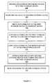
- FIG. 3is a flowchart illustrating a method of improving storage reliability. The steps illustrated in FIG. 3 may be performed by one or more elements of storage system 100 or storage system 200 .
- An indication of the impending failure of a first storage deviceis received ( 302 ).
- RAID controller 120may receive an indication of the impending failure of failing drive 111 .
- Writing data to the first storage deviceis ceased ( 304 ).
- RAID controller 120may cease writing data to failing drive 111 .
- Data directed to the first storage deviceis written to a memory device ( 306 ).
- RAID controller 120may cache data directed to be written to failing drive 111 in nonvolatile memory 130 .
- Data stored on the first storage deviceis copied to a second storage device ( 308 ).
- data stored on failing drive 111may be copied to spare drive 115 by RAID controller 120 .
- the data copied to spare drive 115may come directly from failing drive 111 .
- the data copied to spare drivemay be a reconstruction of the data on failing drive 111 .
- the data stored on failing drive 111may be reconstructed using one or more RAID techniques.
- Data stored on the memory deviceis copied to the second storage device ( 310 ).
- write data that was cached by RAID controller 120 in nonvolatile memory 130may be written to spare drive 115 .
- the RAID groupis operated with the second storage device functioning in place of the first storage device ( 312 ).
- RAID group 140may be operated by RAID controller 120 with spare drive 115 functioning in place of failing drive 111 within RAID group 140 .
- Datais read from the second storage device ( 314 ).
- RAID controller 120may read data from spare drive 115 so that spare drive 115 may function in place of failing drive 111 in RAID group 140 .
- RAID controllermay read data from spare drive 115 in order to copy it to a new drive that has replaced failing drive 111 in RAID group 140 .
- RAID controller 140may then operate the new drive as part of RAID group 140 .
- FIG. 4is a flowchart illustrating a method of improving storage reliability. The steps illustrated in FIG. 4 may be performed by one or more elements of storage system 100 or storage system 200 .
- An indication of the impending failure of a first storage deviceis received ( 402 ).
- RAID controller 220may receive an indication of the impending failure of failing drive 211 .
- Writing data to the first storage deviceis ceased ( 404 ).
- RAID controller 220may cease writing data to failing drive 211 .
- Data directed to the first storage deviceis written to a memory device ( 406 ).
- RAID controller 220may cache data directed to be written to failing drive 211 in nonvolatile memory 230 .
- Data stored on the first storage deviceis copied to an unused portion of a second storage device ( 408 ).
- data stored on failing drive 211may be copied to an unused portion of drive 213 by RAID controller 120 .
- the data copied to the unused portion of drive 213may come directly from failing drive 211 .
- the data copied to the unused portion of drive 213may be a reconstruction of the data on failing drive 211 .
- the data stored on failing drive 211may be reconstructed using one or more RAID techniques.
- Data stored on the memory deviceis copied to the second storage device ( 410 ).
- write data that was cached by RAID controller 220 in nonvolatile memory 230may be written to drive 213 .
- write data that was cached by RAID controller 220 in nonvolatile memory 230may be written to unused drive portion 2131 .
- write data that was cached by RAID controller 220 in nonvolatile memory 230may be written to drive 213 .
- the RAID groupis operated with at least a portion of the second storage device functioning in place of at least a portion the first storage device ( 412 ).
- RAID group 240may be operated by RAID controller 220 with unused drive portion 2131 functioning in place of at least a portion of failing drive 211 within RAID group 240 .
- Datais read from the second storage device ( 414 ).
- RAID controller 220may read data from drive 213 so that unused drive portion 2131 may function in place of at least a portion of failing drive 211 in RAID group 240 .
- RAID controller 240may read data from unused drive portion 2131 in order to copy it to a new drive that has replaced failing drive 211 in RAID group 240 . RAID controller 240 may then operate the new drive as part of RAID group 240 .
Landscapes
- Engineering & Computer Science (AREA)
- Theoretical Computer Science (AREA)
- Quality & Reliability (AREA)
- Physics & Mathematics (AREA)
- General Engineering & Computer Science (AREA)
- General Physics & Mathematics (AREA)
- Techniques For Improving Reliability Of Storages (AREA)
- Debugging And Monitoring (AREA)
Abstract
Description
Claims (15)
Priority Applications (1)
| Application Number | Priority Date | Filing Date | Title |
|---|---|---|---|
| US12/211,188US8127182B2 (en) | 2008-09-16 | 2008-09-16 | Storage utilization to improve reliability using impending failure triggers |
Applications Claiming Priority (1)
| Application Number | Priority Date | Filing Date | Title |
|---|---|---|---|
| US12/211,188US8127182B2 (en) | 2008-09-16 | 2008-09-16 | Storage utilization to improve reliability using impending failure triggers |
Publications (2)
| Publication Number | Publication Date |
|---|---|
| US20100070796A1 US20100070796A1 (en) | 2010-03-18 |
| US8127182B2true US8127182B2 (en) | 2012-02-28 |
Family
ID=42008297
Family Applications (1)
| Application Number | Title | Priority Date | Filing Date |
|---|---|---|---|
| US12/211,188Expired - Fee RelatedUS8127182B2 (en) | 2008-09-16 | 2008-09-16 | Storage utilization to improve reliability using impending failure triggers |
Country Status (1)
| Country | Link |
|---|---|
| US (1) | US8127182B2 (en) |
Cited By (15)
| Publication number | Priority date | Publication date | Assignee | Title |
|---|---|---|---|---|
| US9671960B2 (en) | 2014-09-12 | 2017-06-06 | Netapp, Inc. | Rate matching technique for balancing segment cleaning and I/O workload |
| US9710317B2 (en) | 2015-03-30 | 2017-07-18 | Netapp, Inc. | Methods to identify, handle and recover from suspect SSDS in a clustered flash array |
| US9720601B2 (en) | 2015-02-11 | 2017-08-01 | Netapp, Inc. | Load balancing technique for a storage array |
| US9740566B2 (en) | 2015-07-31 | 2017-08-22 | Netapp, Inc. | Snapshot creation workflow |
| US9762460B2 (en) | 2015-03-24 | 2017-09-12 | Netapp, Inc. | Providing continuous context for operational information of a storage system |
| US9798728B2 (en) | 2014-07-24 | 2017-10-24 | Netapp, Inc. | System performing data deduplication using a dense tree data structure |
| US9836229B2 (en) | 2014-11-18 | 2017-12-05 | Netapp, Inc. | N-way merge technique for updating volume metadata in a storage I/O stack |
| US10133511B2 (en) | 2014-09-12 | 2018-11-20 | Netapp, Inc | Optimized segment cleaning technique |
| US10911328B2 (en) | 2011-12-27 | 2021-02-02 | Netapp, Inc. | Quality of service policy based load adaption |
| US10929022B2 (en) | 2016-04-25 | 2021-02-23 | Netapp. Inc. | Space savings reporting for storage system supporting snapshot and clones |
| US10951488B2 (en) | 2011-12-27 | 2021-03-16 | Netapp, Inc. | Rule-based performance class access management for storage cluster performance guarantees |
| US10997098B2 (en) | 2016-09-20 | 2021-05-04 | Netapp, Inc. | Quality of service policy sets |
| US11379119B2 (en) | 2010-03-05 | 2022-07-05 | Netapp, Inc. | Writing data in a distributed data storage system |
| US11386120B2 (en) | 2014-02-21 | 2022-07-12 | Netapp, Inc. | Data syncing in a distributed system |
| US12443550B2 (en) | 2024-01-15 | 2025-10-14 | Netapp, Inc. | Quality of service policy sets |
Families Citing this family (9)
| Publication number | Priority date | Publication date | Assignee | Title |
|---|---|---|---|---|
| US20120303912A1 (en)* | 2011-05-23 | 2012-11-29 | Microsoft Corporation | Storage account migration between storage stamps |
| TW201301020A (en)* | 2011-06-29 | 2013-01-01 | Giga Byte Tech Co Ltd | Method and system for detect raid and transfer data |
| US8726065B2 (en) | 2011-10-18 | 2014-05-13 | International Business Machines Corporation | Managing failover operations on a cluster of computers |
| US8849939B2 (en)* | 2011-12-02 | 2014-09-30 | International Business Machines Corporation | Coordinating write sequences in a data storage system |
| US20140250269A1 (en)* | 2013-03-01 | 2014-09-04 | Lsi Corporation | Declustered raid pool as backup for raid volumes |
| US9519556B2 (en)* | 2014-09-09 | 2016-12-13 | Dell Products, Lp | Member replacement in an array of information storage devices |
| US10007432B2 (en)* | 2015-10-13 | 2018-06-26 | Dell Products, L.P. | System and method for replacing storage devices |
| US10572323B1 (en)* | 2017-10-24 | 2020-02-25 | EMC IP Holding Company LLC | Predicting physical storage unit health |
| US11695853B1 (en)* | 2022-04-07 | 2023-07-04 | T-Mobile Usa, Inc. | Content management systems providing zero recovery point objective |
Citations (10)
| Publication number | Priority date | Publication date | Assignee | Title |
|---|---|---|---|---|
| US5911779A (en)* | 1991-01-04 | 1999-06-15 | Emc Corporation | Storage device array architecture with copyback cache |
| US6223252B1 (en)* | 1998-05-04 | 2001-04-24 | International Business Machines Corporation | Hot spare light weight mirror for raid system |
| US6571354B1 (en)* | 1999-12-15 | 2003-05-27 | Dell Products, L.P. | Method and apparatus for storage unit replacement according to array priority |
| US6598174B1 (en)* | 2000-04-26 | 2003-07-22 | Dell Products L.P. | Method and apparatus for storage unit replacement in non-redundant array |
| US20040078454A1 (en)* | 2002-10-16 | 2004-04-22 | Abrahams Seth J. | System and method for storage of operational parameters on components |
| US6845465B2 (en)* | 2001-09-17 | 2005-01-18 | Sun Microsystems, Inc. | Method and system for leveraging spares in a data storage system including a plurality of disk drives |
| US7130973B1 (en)* | 2003-08-08 | 2006-10-31 | Sun Microsystems, Inc. | Method and apparatus to restore data redundancy and utilize spare storage spaces |
| US20080151724A1 (en)* | 2006-12-21 | 2008-06-26 | Anderson Robert J | Systems and methods for managing unavailable storage devices |
| US7543178B2 (en)* | 2004-05-06 | 2009-06-02 | International Business Machines Corporation | Low cost RAID with seamless disk failure recovery |
| US7587626B2 (en)* | 2004-12-15 | 2009-09-08 | Dell Products L.P. | Intelligent hotspare or “SmartSpare” drive with pre-emptive drive rebuild |
- 2008
- 2008-09-16USUS12/211,188patent/US8127182B2/ennot_activeExpired - Fee Related
Patent Citations (10)
| Publication number | Priority date | Publication date | Assignee | Title |
|---|---|---|---|---|
| US5911779A (en)* | 1991-01-04 | 1999-06-15 | Emc Corporation | Storage device array architecture with copyback cache |
| US6223252B1 (en)* | 1998-05-04 | 2001-04-24 | International Business Machines Corporation | Hot spare light weight mirror for raid system |
| US6571354B1 (en)* | 1999-12-15 | 2003-05-27 | Dell Products, L.P. | Method and apparatus for storage unit replacement according to array priority |
| US6598174B1 (en)* | 2000-04-26 | 2003-07-22 | Dell Products L.P. | Method and apparatus for storage unit replacement in non-redundant array |
| US6845465B2 (en)* | 2001-09-17 | 2005-01-18 | Sun Microsystems, Inc. | Method and system for leveraging spares in a data storage system including a plurality of disk drives |
| US20040078454A1 (en)* | 2002-10-16 | 2004-04-22 | Abrahams Seth J. | System and method for storage of operational parameters on components |
| US7130973B1 (en)* | 2003-08-08 | 2006-10-31 | Sun Microsystems, Inc. | Method and apparatus to restore data redundancy and utilize spare storage spaces |
| US7543178B2 (en)* | 2004-05-06 | 2009-06-02 | International Business Machines Corporation | Low cost RAID with seamless disk failure recovery |
| US7587626B2 (en)* | 2004-12-15 | 2009-09-08 | Dell Products L.P. | Intelligent hotspare or “SmartSpare” drive with pre-emptive drive rebuild |
| US20080151724A1 (en)* | 2006-12-21 | 2008-06-26 | Anderson Robert J | Systems and methods for managing unavailable storage devices |
Non-Patent Citations (2)
| Title |
|---|
| http://en.wikipedia.org/w/index.php?title=RAID&printable=yes; date retrieved Jun. 18, 2008. |
| Patterson, David; Garth A. Gibson, Randy Katz (1988). "A Case for Redundant Arrays of Inexpensive Disks (RAID)". SIGMOD Conference: pp. 109-116. retrieved Dec. 31, 2006. |
Cited By (21)
| Publication number | Priority date | Publication date | Assignee | Title |
|---|---|---|---|---|
| US11379119B2 (en) | 2010-03-05 | 2022-07-05 | Netapp, Inc. | Writing data in a distributed data storage system |
| US10911328B2 (en) | 2011-12-27 | 2021-02-02 | Netapp, Inc. | Quality of service policy based load adaption |
| US12250129B2 (en) | 2011-12-27 | 2025-03-11 | Netapp, Inc. | Proportional quality of service based on client usage and system metrics |
| US11212196B2 (en) | 2011-12-27 | 2021-12-28 | Netapp, Inc. | Proportional quality of service based on client impact on an overload condition |
| US10951488B2 (en) | 2011-12-27 | 2021-03-16 | Netapp, Inc. | Rule-based performance class access management for storage cluster performance guarantees |
| US11386120B2 (en) | 2014-02-21 | 2022-07-12 | Netapp, Inc. | Data syncing in a distributed system |
| US9798728B2 (en) | 2014-07-24 | 2017-10-24 | Netapp, Inc. | System performing data deduplication using a dense tree data structure |
| US10133511B2 (en) | 2014-09-12 | 2018-11-20 | Netapp, Inc | Optimized segment cleaning technique |
| US10210082B2 (en) | 2014-09-12 | 2019-02-19 | Netapp, Inc. | Rate matching technique for balancing segment cleaning and I/O workload |
| US9671960B2 (en) | 2014-09-12 | 2017-06-06 | Netapp, Inc. | Rate matching technique for balancing segment cleaning and I/O workload |
| US10365838B2 (en) | 2014-11-18 | 2019-07-30 | Netapp, Inc. | N-way merge technique for updating volume metadata in a storage I/O stack |
| US9836229B2 (en) | 2014-11-18 | 2017-12-05 | Netapp, Inc. | N-way merge technique for updating volume metadata in a storage I/O stack |
| US9720601B2 (en) | 2015-02-11 | 2017-08-01 | Netapp, Inc. | Load balancing technique for a storage array |
| US9762460B2 (en) | 2015-03-24 | 2017-09-12 | Netapp, Inc. | Providing continuous context for operational information of a storage system |
| US9710317B2 (en) | 2015-03-30 | 2017-07-18 | Netapp, Inc. | Methods to identify, handle and recover from suspect SSDS in a clustered flash array |
| US9740566B2 (en) | 2015-07-31 | 2017-08-22 | Netapp, Inc. | Snapshot creation workflow |
| US10929022B2 (en) | 2016-04-25 | 2021-02-23 | Netapp. Inc. | Space savings reporting for storage system supporting snapshot and clones |
| US11327910B2 (en) | 2016-09-20 | 2022-05-10 | Netapp, Inc. | Quality of service policy sets |
| US10997098B2 (en) | 2016-09-20 | 2021-05-04 | Netapp, Inc. | Quality of service policy sets |
| US11886363B2 (en) | 2016-09-20 | 2024-01-30 | Netapp, Inc. | Quality of service policy sets |
| US12443550B2 (en) | 2024-01-15 | 2025-10-14 | Netapp, Inc. | Quality of service policy sets |
Also Published As
| Publication number | Publication date |
|---|---|
| US20100070796A1 (en) | 2010-03-18 |
Similar Documents
| Publication | Publication Date | Title |
|---|---|---|
| US8127182B2 (en) | Storage utilization to improve reliability using impending failure triggers | |
| US8069301B2 (en) | Apparatus, storage system, and computer program product for prevention of data loss | |
| US5566316A (en) | Method and apparatus for hierarchical management of data storage elements in an array storage device | |
| JP5768587B2 (en) | Storage system, storage control device, and storage control method | |
| US8356292B2 (en) | Method for updating control program of physical storage device in storage virtualization system and storage virtualization controller and system thereof | |
| US7739544B2 (en) | Disk array system and rebuild method thereof | |
| US8307159B2 (en) | System and method for providing performance-enhanced rebuild of a solid-state drive (SSD) in a solid-state drive hard disk drive (SSD HDD) redundant array of inexpensive disks 1 (RAID 1) pair | |
| CN101523353B (en) | Method for optimized rebuilding and copying back of a failed drive in the presence of a global hot spare | |
| US6892276B2 (en) | Increased data availability in raid arrays using smart drives | |
| US20090327603A1 (en) | System including solid state drives paired with hard disk drives in a RAID 1 configuration and a method for providing/implementing said system | |
| US20120023287A1 (en) | Storage apparatus and control method thereof | |
| US20110264949A1 (en) | Disk array | |
| US20120297258A1 (en) | Apparatus, System, and Method for Bad Block Remapping | |
| KR101251245B1 (en) | Optimized reconstruction and copyback methodology for a disconnected drive in the presence of a global hot spare disk | |
| JP2022017215A (en) | How the storage device operates and the system including the storage device | |
| US20070101188A1 (en) | Method for establishing stable storage mechanism | |
| US20100306466A1 (en) | Method for improving disk availability and disk array controller | |
| JPWO2009130848A1 (en) | Storage system and storage system control method | |
| US20110202791A1 (en) | Storage control device , a storage system, a storage control method and a program thereof | |
| EP2573689A1 (en) | Method and device for implementing redundant array of independent disk protection in file system | |
| CN104166601B (en) | The backup method and device of a kind of data storage | |
| CN104050056A (en) | File system backup of multi-storage-medium device | |
| US20070088990A1 (en) | System and method for reduction of rebuild time in raid systems through implementation of striped hot spare drives | |
| JP6515752B2 (en) | Storage control device, control method, and control program | |
| US10795790B2 (en) | Storage control apparatus, method and non-transitory computer-readable storage medium |
Legal Events
| Date | Code | Title | Description |
|---|---|---|---|
| AS | Assignment | Owner name:LSI CORPORATION,CALIFORNIA Free format text:ASSIGNMENT OF ASSIGNORS INTEREST;ASSIGNORS:SIVAPERUMAN, GANESH;KAMALAVANNAN, HARIHARAN;DHANARAJAN, SURESH;AND OTHERS;REEL/FRAME:021534/0618 Effective date:20080912 Owner name:LSI CORPORATION, CALIFORNIA Free format text:ASSIGNMENT OF ASSIGNORS INTEREST;ASSIGNORS:SIVAPERUMAN, GANESH;KAMALAVANNAN, HARIHARAN;DHANARAJAN, SURESH;AND OTHERS;REEL/FRAME:021534/0618 Effective date:20080912 | |
| FEPP | Fee payment procedure | Free format text:PAYER NUMBER DE-ASSIGNED (ORIGINAL EVENT CODE: RMPN); ENTITY STATUS OF PATENT OWNER: LARGE ENTITY Free format text:PAYOR NUMBER ASSIGNED (ORIGINAL EVENT CODE: ASPN); ENTITY STATUS OF PATENT OWNER: LARGE ENTITY | |
| AS | Assignment | Owner name:DEUTSCHE BANK AG NEW YORK BRANCH, AS COLLATERAL AG Free format text:PATENT SECURITY AGREEMENT;ASSIGNORS:LSI CORPORATION;AGERE SYSTEMS LLC;REEL/FRAME:032856/0031 Effective date:20140506 | |
| AS | Assignment | Owner name:AVAGO TECHNOLOGIES GENERAL IP (SINGAPORE) PTE. LTD Free format text:ASSIGNMENT OF ASSIGNORS INTEREST;ASSIGNOR:LSI CORPORATION;REEL/FRAME:035390/0388 Effective date:20140814 | |
| REMI | Maintenance fee reminder mailed | ||
| AS | Assignment | Owner name:LSI CORPORATION, CALIFORNIA Free format text:TERMINATION AND RELEASE OF SECURITY INTEREST IN PATENT RIGHTS (RELEASES RF 032856-0031);ASSIGNOR:DEUTSCHE BANK AG NEW YORK BRANCH, AS COLLATERAL AGENT;REEL/FRAME:037684/0039 Effective date:20160201 Owner name:AGERE SYSTEMS LLC, PENNSYLVANIA Free format text:TERMINATION AND RELEASE OF SECURITY INTEREST IN PATENT RIGHTS (RELEASES RF 032856-0031);ASSIGNOR:DEUTSCHE BANK AG NEW YORK BRANCH, AS COLLATERAL AGENT;REEL/FRAME:037684/0039 Effective date:20160201 | |
| LAPS | Lapse for failure to pay maintenance fees | ||
| STCH | Information on status: patent discontinuation | Free format text:PATENT EXPIRED DUE TO NONPAYMENT OF MAINTENANCE FEES UNDER 37 CFR 1.362 | |
| FP | Lapsed due to failure to pay maintenance fee | Effective date:20160228 |