US8126678B2 - Methods of monitoring electronic displays within a display network - Google Patents
Methods of monitoring electronic displays within a display networkDownload PDFInfo
- Publication number
- US8126678B2 US8126678B2US12/553,500US55350009AUS8126678B2US 8126678 B2US8126678 B2US 8126678B2US 55350009 AUS55350009 AUS 55350009AUS 8126678 B2US8126678 B2US 8126678B2
- Authority
- US
- United States
- Prior art keywords
- display
- thumbnail
- electronic displays
- thumbnails
- network
- Prior art date
- Legal status (The legal status is an assumption and is not a legal conclusion. Google has not performed a legal analysis and makes no representation as to the accuracy of the status listed.)
- Active
Links
Images


Classifications
- G—PHYSICS
- G09—EDUCATION; CRYPTOGRAPHY; DISPLAY; ADVERTISING; SEALS
- G09F—DISPLAYING; ADVERTISING; SIGNS; LABELS OR NAME-PLATES; SEALS
- G09F9/00—Indicating arrangements for variable information in which the information is built-up on a support by selection or combination of individual elements
- G09F9/30—Indicating arrangements for variable information in which the information is built-up on a support by selection or combination of individual elements in which the desired character or characters are formed by combining individual elements
- G—PHYSICS
- G06—COMPUTING OR CALCULATING; COUNTING
- G06Q—INFORMATION AND COMMUNICATION TECHNOLOGY [ICT] SPECIALLY ADAPTED FOR ADMINISTRATIVE, COMMERCIAL, FINANCIAL, MANAGERIAL OR SUPERVISORY PURPOSES; SYSTEMS OR METHODS SPECIALLY ADAPTED FOR ADMINISTRATIVE, COMMERCIAL, FINANCIAL, MANAGERIAL OR SUPERVISORY PURPOSES, NOT OTHERWISE PROVIDED FOR
- G06Q30/00—Commerce
- G06Q30/02—Marketing; Price estimation or determination; Fundraising
- G06Q30/0241—Advertisements
Definitions
- the present inventionrelates generally to electronic displays and, more specifically, to monitoring operation of one or more electronic displays within a display network.
- displayshave become electronic, using lights, light emitting diodes (LEDs), and other electronic devices to display visual content that can be easily adaptable to display a wide variety of messages in the form of words and images from the same display without having to physically change the characteristics of the display.
- These electronic displayscan easily modify a graphic image or message to create video displays and modify the type of message or advertisement that is shown on the electronic display at regular intervals, or at targeted times depending on expected traffic near the display, or public interest.
- These possible imagesare generally referred to herein as visual content.
- the visual contentis delivered to the physical location and affixed to the display.
- the visual contentmust still be delivered to the physical location, but the content delivery may be performed electronically.
- traditional displaysmay display the same message for weeks or months at a time, electronic displays enable the message to be changed easily and often. Thus, it may be possible to modify the visual content many times in a single day.
- electronic displaysmay be networked together such that the displays may communicate with each other, or with a central computer.
- One embodiment of the present inventioncomprises a method of monitoring at least one electronic display within a display network.
- the methodcomprises performing at least one diagnostic operation on at least one electronic display including at least one camera, a display element, and a display server.
- the methodfurther includes transmitting data relating to the at least one diagnostic operation to a network remote from the at least one electronic display. Additionally, the method includes displaying the data within the network.
- Another embodiment of the present inventioncomprises a method of monitoring a display network.
- the methodcomprises performing at least one diagnostic operation on at least one electronic display having at least one camera, a display element, and a display server operably coupled to a remote network.
- the methodcomprises transmitting graphical information to the remote network and displaying the graphical information in a thumbnail explosion on a display device within the remote network.
- Yet another embodiment of the present inventioncomprises a computer-readable media storage storing instructions that when executed by a processor cause the processor to perform instructions for monitoring at least one electronic display within a display network according to an embodiment of the present invention.
- FIG. 1is a block diagram of a display network in accordance with a representative embodiment of the invention
- FIG. 2is a block diagram of a remote network in accordance with an embodiment of the invention.
- FIG. 3is a block diagram of an image viewer including graphical information according to an embodiment of the invention.
- FIGS. 4A and 4Bare illustrations of an enlarged thumbnail image and a video in accordance with an embodiment of the invention.
- Embodiments of the present inventionprovide methods for monitoring the operation of electronic displays that are configured as part of a network of electronic displays and enables a system operator to view images and/or videos of the visual content displayed by each electronic display. Furthermore, a system operator may view results of diagnostic operations performed on each electronic display.
- FIG. 1illustrates a display network 100 in accordance with a representative embodiment of the invention.
- Display network 100may include at least one electronic display 110 and a remote network 130 .
- electronic displays 110may be located at different geographical locations.
- electronic displays 110may be roadside billboards that are located at different locations within a city, or they may be located at different geographical locations across a country, or around the world.
- Each electronic display 110may include a display element 112 , a display server 120 , and a camera element 122 .
- Each electronic display 110is configured to present visual content in the forms of text, still images, animations, and video images, and may also be configured to present audio content.
- the visual contentmay include combinations of visual content in the form of text, still images, animations and video images in the form of adjacent portions of the display carrying different types of media content as well as overlays of different types of content on top of other types of content.
- the media contentmay include both visual content and audio content.
- the audio contentmay be synchronized to video images or various aspects of still images and animations as are known by those of ordinary skill in the art.
- Electronic displaysmay take on a number of forms and formats.
- electronic displaysmay be in the form of billboards, displays on busses, displays on bus shelters, mall directory signs, airport signs, signs in sporting and other event arenas, signs on taxis, and any other place where displays are used by multiple advertisers.
- the visual contentmay be formatted in any suitable format for presenting and transmitting video, still images, and text.
- some of the formatsmay include ASCII text, graphic interchange formats (GIF), bitmap (BMP) formats, Joint Photographic Experts Group (JPEG) formats, Moving Picture Experts Group (MPEG) formats, and the like.
- the audio contentmay be formatted in any suitable format for presenting and transporting audio.
- some of the formatsmay include MPEG-1 Audio Layer III (MP3), Waveform Audio File (WAV), WINDOWS MEDIA® audio (WMA), Advanced Audio Coding (AAC), and the like.
- Display elements 112may be configured with lights, LEDs, Liquid Crystal Displays (LCDs), plasma displays, and the like.
- Display server 120may include a processor and a memory and may be configured for receiving and storing media content to be presented on the corresponding electronic display 110 at some scheduled time.
- Display server 120may include functions such as, for example, formatting the content for its electronic display 110 , animating the content for its electronic display 110 , controlling presentation of content on the display element 112 , controlling presentation of audio content on an audio element (not shown), controlling timing of various content on the display element 112 , controlling timing of various content on the audio element, and communicating with the remote network 130 .
- display server 120may perform diagnostic operations on the corresponding electronic display 110 .
- display server 120may be configured to perform a diagnostic test on each LED within display element 112 in order to determine the condition of each LED.
- display server 120may determine the optical power output of each LED by sensing brightness and temperature levels from light and temperature sensors located adjacent each LED within display element 112 .
- photodetector chipsmay be placed in close proximity to each LED in display element 112 to measure light output of each LED during image display.
- display server 120may be configured to determine an ambient light level of display element 112 and calibrate a brightness setting of display element 112 accordingly.
- display server 120may be configured to run diagnostic tests on one or more power supplies within a corresponding electronic display 110 to determine whether the power supplies are functioning properly. Display server 120 may also be configured to perform diagnostic tests to determine whether circuitry within electronic display 110 is functioning properly. In addition, display server 120 may be configured to determine a version of a software program currently running on display server 120 . As described in greater detail below, results, faults, or errors generated by the diagnostic operations performed by display server 120 may be transmitted to, stored and displayed within remote network 130 .
- Camera element 122may include one or more cameras configured and positioned to provide a still image and/or a real-time video of display element 112 . Furthermore, camera element 122 may include one or more cameras configured and positioned to provide a still image and/or a real-time video of an area near display element 112 such as, for example, an area with automobiles or pedestrians that are approaching display element 112 (i.e., oncoming traffic). As described in more detail below, images or videos taken by camera element 122 may be transmitted to, stored and displayed within remote network 130 .
- Remote network 130may be configured to control one or more electronic displays 110 and communicate with each electronic display 110 across a display communication link 115 .
- the display communication link 115may be any suitable communication link, such as, for example, any suitable direct-wired communication bus, satellite link, direct telephone line, wireless telephone link, or other wireless data links.
- the display communication link 115may be intermittent or continuous. As a continuous communication example, with sufficient bandwidth a continuous communication link may be established to distribute media content as substantially real-time video directly to the electronic display 110 .
- a communication linkmay be established between the electronic display 110 and the remote network 130 for short bursts of time to communicate information such as display status, media content, scheduling information, new software/firmware for the display server 120 , and the like. Furthermore, the communication link may be initiated from either the electronic display 110 or the remote network 130 .
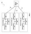
- FIG. 2illustrates a block diagram of remote network 130 including a network server 132 and display device 302 .
- Network server 132may include a processor 304 and a memory 306 having an application program 310 stored therein.
- the memory 306may include: volatile memory such as dynamic random access memory (DRAM), or static random access memory (SRAM); non-volatile memory, such as Flash memory; and long-term storage in the form of magnetic media, such as hard disk drives, and optical media, such as compact disc read-only memory (CD-ROM), and digital versatile disc read-only memory (DVD-ROM).
- volatile memorysuch as dynamic random access memory (DRAM), or static random access memory (SRAM)
- non-volatile memorysuch as Flash memory
- long-term storage in the form of magnetic mediasuch as hard disk drives, and optical media, such as compact disc read-only memory (CD-ROM), and digital versatile disc read-only memory (DVD-ROM).
- CD-ROMcompact disc read-only memory
- DVD-ROMdigital versatile disc read-only memory
- Application program 310may operate under control of an operating system (not shown) stored in memory 306 , and interfaced with a user to accept inputs and commands and to present outputs through a graphical user interface (GUI) 400 (see FIG. 3 ).
- GUI 400graphical user interface
- display viewer 400may be displayed within a display device 302 .
- display device 302may include a flat-screen television.
- Portions of application program 310may be distributed such that some of application program 310 may be included within remote network 130 and some of the application program 310 may be included within electronic display 110 (see FIG. 1 ).
- Application program 310may be configured to cause the network server 132 to connect to one or more electronic displays 110 (see FIG. 1 ) via the remote network 130 and communication link 115 (see FIG. 1 ). Upon successful connection to an electronic display 110 , application program 310 may be configured to retrieve a real-time video and/or at least one image from a camera within camera element 122 . Images retrieved from camera element 122 may be stored within memory 306 by application program 310 and archived in a slide-show video format for subsequent viewing. Viewing images in a slide-show format may allow a system operator to detect gradual changes in display element 112 (traffic). In addition, application program 310 may be configured to transmit images to a remote website to allow a customer to view images of their display by accessing the remote website. Application program 310 may also be configured to retrieve any diagnostic information generated from display server 120 within the electronic display 110 . As described above, diagnostic information may include, but is not limited to, diagnostic results, faults, or errors generated by display server 120 .
- application program 310may be configured to retrieve additional data from electronic display 110 .
- application program 310may retrieve a temperature value of one or more central processing units (CPUs) and/or one or more motherboards located within electronic display 110 .
- CPUscentral processing units
- a fan speed of one or more fans located within electronic display 110may also be retrieved by application program 310 .
- application program 310may be configured to cause the network server 132 to connect to and request images, videos, data and/or diagnostic information from each electronic display 110 every five seconds.
- application program 310may also perform diagnostic operations on electronic displays 110 .
- application program 310may be configured to determine whether a network connection is established with an electronic display 110 . To determine whether a network connection exists, application program 310 may send a query, such as a “ping,” to a specific electronic display 110 and, thereafter, application program 310 may wait for a response from the electronic display 110 . In the event that application program 310 receives a response from the electronic display 110 , a network connection exists. If no response is received from electronic display 110 , an operating network connection may not exist.
- application program 310may be configured to determine whether each camera within camera element 122 is powered-on and in communication with application program 310 . Additionally, application program 310 may be configured to determine whether display server 120 is powered-on and operating properly.
- Application program 310may be configured to display images, videos, data, and/or any other diagnostic information pertinent to electronic displays 110 .
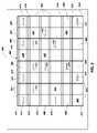
- FIG. 3illustrates display viewer 400 comprising graphical information.
- the graphical informationmay be in the form of a thumbnail explosion 402 of thumbnails 404 , which may include images 406 taken by camera element 122 (see FIG. 1 ) of an electronic display 110 .
- thumbnails 404may include data and/or diagnostic information relating to the corresponding electronic display 110 .
- a name of the electronic device 110 from which image 406 was takenmay be displayed in a thumbnail, such as in region 410 .
- a brightness value of display element 112 , the time at the location of the electronic display 110 that image 406 was taken, and the current time at the location of network server 132may be displayed in a thumbnail, such as in region 412 .
- a status of display server 120may also be displayed in a thumbnail, such as in region 412 .
- Thumbnails 404may also include additional data or diagnostic information across a portion 414 of image 406 , such as, for example, a status of a camera within camera element 122 .
- a “camera down” or a “camera skipped” messagemay be displayed within portion 414 .
- Thumbnails 404 including images 406 , data, or diagnostic information relating to an electronic display 110may quickly alert a system user, such as a maintenance technician within remote network 130 , of any current or potential problems with electronic display 110 .
- a system usermay select a thumbnail 404 to generate a blown-up or enlarged version 500 , as shown in FIG. 4A , of the selected thumbnail 404 displayed in a window 502 .
- a system usermay select and enlarge a thumbnail 404 for further inquiry.
- Enlarged version 500may also include more detailed information relating to diagnostic tests performed on electronic display 110 .
- a system usermay choose a “live mode” option to receive real-time video and receive real-time diagnostic information from electronic display 110 .
- a system operatorwishes to view a real-time video or receive real-time diagnostic information from a specific electronic display 110
- the system usermay select a representative thumbnail and a video player 550 , as shown in FIG. 4B , configured to play a real-time video and display real-time information may be loaded. Thereafter, a corresponding live video 552 and/or real-time information may be provided.
- Real-time video and real-time diagnostic informationmay be helpful for various reasons.
- real-time diagnostic information relating to an electronic display 110may quickly alert maintenance personnel within remote network 130 of any current or potential future problems with electronic display 110 .
- a technician or system user located within network 130may, in real time, view and assist in repairs being made at electronic display 110 by another individual, such as a subcontractor.
- a real-time videomay serve as a method of proving that an individual, such as a subcontractor, performed the work reported at the location of electronic display 110 .
- thumbnails 404 within thumbnail explosion 402may be sorted according to various parameters, such as geographical region, customer, market, or electronic display 110 . Therefore, thumbnail explosion 402 may include thumbnails 404 relating to a single electronic display 110 , thumbnails 404 relating to one or more electronic displays 110 , which all belong to a single customer, or thumbnails 404 relating to one or more electronic displays 110 within a geographic location or market.
- Display viewer 400may also include various features to allow a system user to set operating preferences of application program 310 (see FIG. 2 ) or the output configuration of display viewer 400 . For example, a system user may choose how thumbnails 404 are sorted within display viewer 400 or the size of thumbnails 404 displayed within display viewer 400 . As another example, a system user may choose to generate a text file comprising diagnostic reports of all electronic displays 110 within a display network 100 (see FIG. 1 ). Furthermore, a system user may choose how many attempts application program 310 may carry out to establish a connection with an electronic display 110 .
- display server 120may continuously perform various diagnostic operations on the corresponding electronic display 110 .
- diagnostic operationsmay include determining the conditions of each LED within display element 112 , calibrating a brightness setting of display element 112 , determining a current version of a software program running on display server 120 , and performing pass/fail tests for circuitry within electronic display 110 .
- application program 310may attempt to connect to one or more electronic displays 110 . Upon connection, application program 310 may request information, including images, video, data, or diagnostic information, from electronic displays 110 .
- application program 310may perform diagnostic operations on one or more electronic displays 110 . Diagnostic operations performed by application program 310 may include determining whether a network connection exists with an electronic display 110 , determining whether each camera within camera element 122 is powered-on and in communication with application program 310 , and determining whether display server 120 is powered-on and operating properly.
- network server 132may store the data within remote network 130 .
- application program 310may display a thumbnail explosion 402 including at least one thumbnail 404 that may include an image and any pertinent data or diagnostic information corresponding to the electronic display 110 .
- a system operator within network 130may select a thumbnail 404 in order to receive a larger version 500 of the selected thumbnail and more detailed diagnostic information, if available. Furthermore, a system operator may initiate a “live mode” video corresponding to a thumbnail 404 of interest. In “live mode,” a system operator may select a thumbnail 404 and view a live video 552 and receive real-time diagnostic information corresponding to the electronic display 110 depicted in the selected thumbnail.
- a computer-readable mediumincludes, but is not limited to, magnetic and optical storage devices such as disk drives, magnetic tape, CDs (compact discs), DVDs (digital versatile discs or digital video discs), and semiconductor devices such as RAM, DRAM, ROM, EPROM, and Flash memory.
- magnetic and optical storage devicessuch as disk drives, magnetic tape, CDs (compact discs), DVDs (digital versatile discs or digital video discs), and semiconductor devices such as RAM, DRAM, ROM, EPROM, and Flash memory.
Landscapes
- Physics & Mathematics (AREA)
- General Physics & Mathematics (AREA)
- Engineering & Computer Science (AREA)
- Theoretical Computer Science (AREA)
- Controls And Circuits For Display Device (AREA)
Abstract
Description
Claims (20)
Priority Applications (2)
| Application Number | Priority Date | Filing Date | Title |
|---|---|---|---|
| US12/553,500US8126678B2 (en) | 2007-08-16 | 2009-09-03 | Methods of monitoring electronic displays within a display network |
| US13/398,660US9940854B2 (en) | 2007-08-16 | 2012-02-16 | Methods of monitoring electronic displays within a display network |
Applications Claiming Priority (2)
| Application Number | Priority Date | Filing Date | Title |
|---|---|---|---|
| US11/840,091US7596471B1 (en) | 2007-08-16 | 2007-08-16 | Methods of monitoring electronic displays within a display network |
| US12/553,500US8126678B2 (en) | 2007-08-16 | 2009-09-03 | Methods of monitoring electronic displays within a display network |
Related Parent Applications (1)
| Application Number | Title | Priority Date | Filing Date |
|---|---|---|---|
| US11/840,091ContinuationUS7596471B1 (en) | 2007-08-16 | 2007-08-16 | Methods of monitoring electronic displays within a display network |
Related Child Applications (1)
| Application Number | Title | Priority Date | Filing Date |
|---|---|---|---|
| US13/398,660ContinuationUS9940854B2 (en) | 2007-08-16 | 2012-02-16 | Methods of monitoring electronic displays within a display network |
Publications (2)
| Publication Number | Publication Date |
|---|---|
| US20090319231A1 US20090319231A1 (en) | 2009-12-24 |
| US8126678B2true US8126678B2 (en) | 2012-02-28 |
Family
ID=41109876
Family Applications (3)
| Application Number | Title | Priority Date | Filing Date |
|---|---|---|---|
| US11/840,091ActiveUS7596471B1 (en) | 2007-08-16 | 2007-08-16 | Methods of monitoring electronic displays within a display network |
| US12/553,500ActiveUS8126678B2 (en) | 2007-08-16 | 2009-09-03 | Methods of monitoring electronic displays within a display network |
| US13/398,660Active2030-07-15US9940854B2 (en) | 2007-08-16 | 2012-02-16 | Methods of monitoring electronic displays within a display network |
Family Applications Before (1)
| Application Number | Title | Priority Date | Filing Date |
|---|---|---|---|
| US11/840,091ActiveUS7596471B1 (en) | 2007-08-16 | 2007-08-16 | Methods of monitoring electronic displays within a display network |
Family Applications After (1)
| Application Number | Title | Priority Date | Filing Date |
|---|---|---|---|
| US13/398,660Active2030-07-15US9940854B2 (en) | 2007-08-16 | 2012-02-16 | Methods of monitoring electronic displays within a display network |
Country Status (1)
| Country | Link |
|---|---|
| US (3) | US7596471B1 (en) |
Cited By (1)
| Publication number | Priority date | Publication date | Assignee | Title |
|---|---|---|---|---|
| US8866911B1 (en)* | 2013-12-09 | 2014-10-21 | American Megatrends, Inc. | Digital signage device capable of entering diagnostic display mode |
Families Citing this family (12)
| Publication number | Priority date | Publication date | Assignee | Title |
|---|---|---|---|---|
| US7596471B1 (en)* | 2007-08-16 | 2009-09-29 | Young Electric Sign Company | Methods of monitoring electronic displays within a display network |
| US8171507B2 (en)* | 2008-02-29 | 2012-05-01 | Sony Corporation | Using network server to establish TV setting |
| KR101952260B1 (en)* | 2012-04-03 | 2019-02-26 | 삼성전자주식회사 | Video display terminal and method for displaying a plurality of video thumbnail simultaneously |
| US10593175B1 (en) | 2013-07-01 | 2020-03-17 | Outdoorlink, Inc. | Systems and methods for monitoring advertisements |
| US10185969B1 (en)* | 2013-07-01 | 2019-01-22 | Outdoorlink, Inc. | Systems and methods for monitoring advertisements |
| US10031711B2 (en)* | 2014-12-09 | 2018-07-24 | Imtech Corporation | System and method for facilitating video redundancy |
| CA3024512C (en)* | 2016-05-31 | 2020-12-29 | Manufacturing Resources International, Inc. | Electronic display remote image verification system and method |
| JP2019149767A (en)* | 2018-02-28 | 2019-09-05 | パナソニック液晶ディスプレイ株式会社 | Display device calibration system, display device, photographing device, server device, and display device calibration method |
| US11670202B2 (en) | 2019-01-24 | 2023-06-06 | Outdoorlink, Inc. | Systems and methods for monitoring electronic displays |
| US10965937B2 (en) | 2019-01-24 | 2021-03-30 | Outdoorlink, Inc. | Systems and methods for monitoring electronic displays |
| US11895362B2 (en) | 2021-10-29 | 2024-02-06 | Manufacturing Resources International, Inc. | Proof of play for images displayed at electronic displays |
| WO2024173617A1 (en)* | 2023-02-15 | 2024-08-22 | Oshkosh Corporation | Lift device and locking assembly for a lift device |
Citations (18)
| Publication number | Priority date | Publication date | Assignee | Title |
|---|---|---|---|---|
| US6154771A (en)* | 1998-06-01 | 2000-11-28 | Mediastra, Inc. | Real-time receipt, decompression and play of compressed streaming video/hypervideo; with thumbnail display of past scenes and with replay, hyperlinking and/or recording permissively intiated retrospectively |
| US6349330B1 (en)* | 1997-11-07 | 2002-02-19 | Eigden Video | Method and appparatus for generating a compact post-diagnostic case record for browsing and diagnostic viewing |
| US6424998B2 (en) | 1999-04-28 | 2002-07-23 | World Theatre, Inc. | System permitting the display of video or still image content on selected displays of an electronic display network according to customer dictates |
| US6430603B2 (en) | 1999-04-28 | 2002-08-06 | World Theatre, Inc. | System for direct placement of commercial advertising, public service announcements and other content on electronic billboard displays |
| US6430605B2 (en)* | 1999-04-28 | 2002-08-06 | World Theatre, Inc. | System permitting retail stores to place advertisements on roadside electronic billboard displays that tie into point of purchase displays at stores |
| US20030068087A1 (en)* | 2001-10-05 | 2003-04-10 | Watson Wu | System and method for generating a character thumbnail sequence |
| US20040095396A1 (en) | 2002-11-19 | 2004-05-20 | Stavely Donald J. | Video thumbnail |
| US6741271B1 (en) | 2000-07-31 | 2004-05-25 | Hewlett-Packard Development Company, L.P. | Thumbnail address book for linked family of imaging appliances |
| US20040128691A1 (en) | 2002-12-25 | 2004-07-01 | Fuji Xerox Co., Ltd. | Video browsing system, distribution server and browse client |
| US20050069107A1 (en)* | 2001-10-30 | 2005-03-31 | Masahide Tanaka | Image accumulating apparatus, image accumulation support apparatus, image accumulation system, image control apparatus, image storage apparatus |
| US20060064716A1 (en)* | 2000-07-24 | 2006-03-23 | Vivcom, Inc. | Techniques for navigating multiple video streams |
| US7038637B1 (en) | 1999-04-22 | 2006-05-02 | Si Diamond Technology, Inc. | System and method for selling advertising space on electronic billboards over the internet |
| US7088335B2 (en)* | 1999-04-28 | 2006-08-08 | Novus Partners Llc | Methods and apparatus for ultra-violet stimulated displays |
| US20070204032A1 (en)* | 2006-02-24 | 2007-08-30 | Strand Michael J | Locally responsive kiosk signage from on-line source |
| US20080109856A1 (en) | 2006-10-24 | 2008-05-08 | Beland Graham N | System and method for content planning in electronic displays |
| US20080192840A1 (en)* | 2007-02-09 | 2008-08-14 | Microsoft Corporation | Smart video thumbnail |
| US20080201208A1 (en)* | 2007-02-14 | 2008-08-21 | Thomas Hiramatsu Tie | Advertising system and method |
| US7596471B1 (en)* | 2007-08-16 | 2009-09-29 | Young Electric Sign Company | Methods of monitoring electronic displays within a display network |
Family Cites Families (9)
| Publication number | Priority date | Publication date | Assignee | Title |
|---|---|---|---|---|
| CA2403270C (en)* | 2000-03-14 | 2011-05-17 | Joseph Robert Marchese | Digital video system using networked cameras |
| EP1290541A1 (en)* | 2000-05-17 | 2003-03-12 | E-Magin Display Technologies Ltd. | Electronic billboard with reflective color liquid crystal displays |
| CA2451656C (en)* | 2001-06-29 | 2009-05-26 | Novus Communications Technologies | Dynamic device and method for billboard advertising |
| US6961908B2 (en)* | 2001-12-05 | 2005-11-01 | International Business Machines Corporation | System and method for navigating graphical images |
| US20030115096A1 (en)* | 2001-12-17 | 2003-06-19 | Reynolds Randy B. | Computer-controlled, remotely programmed at-shelf advertising system |
| AU2004235139A1 (en)* | 2003-04-25 | 2004-11-11 | Visioneered Image Systems, Inc. | Led illumination source/display with individual led brightness monitoring capability and calibration method |
| JP2006189924A (en)* | 2004-12-28 | 2006-07-20 | Kyocera Mita Corp | Image display program and image display apparatus |
| JP4830436B2 (en)* | 2005-10-03 | 2011-12-07 | 株式会社日立製作所 | Display device |
| US7502950B1 (en)* | 2006-04-26 | 2009-03-10 | Daktronics, Inc. | Dual power supply switching system operating in parallel for providing power to a plurality of LED display modules |
- 2007
- 2007-08-16USUS11/840,091patent/US7596471B1/enactiveActive
- 2009
- 2009-09-03USUS12/553,500patent/US8126678B2/enactiveActive
- 2012
- 2012-02-16USUS13/398,660patent/US9940854B2/enactiveActive
Patent Citations (18)
| Publication number | Priority date | Publication date | Assignee | Title |
|---|---|---|---|---|
| US6349330B1 (en)* | 1997-11-07 | 2002-02-19 | Eigden Video | Method and appparatus for generating a compact post-diagnostic case record for browsing and diagnostic viewing |
| US6154771A (en)* | 1998-06-01 | 2000-11-28 | Mediastra, Inc. | Real-time receipt, decompression and play of compressed streaming video/hypervideo; with thumbnail display of past scenes and with replay, hyperlinking and/or recording permissively intiated retrospectively |
| US7038637B1 (en) | 1999-04-22 | 2006-05-02 | Si Diamond Technology, Inc. | System and method for selling advertising space on electronic billboards over the internet |
| US7088335B2 (en)* | 1999-04-28 | 2006-08-08 | Novus Partners Llc | Methods and apparatus for ultra-violet stimulated displays |
| US6424998B2 (en) | 1999-04-28 | 2002-07-23 | World Theatre, Inc. | System permitting the display of video or still image content on selected displays of an electronic display network according to customer dictates |
| US6430603B2 (en) | 1999-04-28 | 2002-08-06 | World Theatre, Inc. | System for direct placement of commercial advertising, public service announcements and other content on electronic billboard displays |
| US6430605B2 (en)* | 1999-04-28 | 2002-08-06 | World Theatre, Inc. | System permitting retail stores to place advertisements on roadside electronic billboard displays that tie into point of purchase displays at stores |
| US20060064716A1 (en)* | 2000-07-24 | 2006-03-23 | Vivcom, Inc. | Techniques for navigating multiple video streams |
| US6741271B1 (en) | 2000-07-31 | 2004-05-25 | Hewlett-Packard Development Company, L.P. | Thumbnail address book for linked family of imaging appliances |
| US20030068087A1 (en)* | 2001-10-05 | 2003-04-10 | Watson Wu | System and method for generating a character thumbnail sequence |
| US20050069107A1 (en)* | 2001-10-30 | 2005-03-31 | Masahide Tanaka | Image accumulating apparatus, image accumulation support apparatus, image accumulation system, image control apparatus, image storage apparatus |
| US20040095396A1 (en) | 2002-11-19 | 2004-05-20 | Stavely Donald J. | Video thumbnail |
| US20040128691A1 (en) | 2002-12-25 | 2004-07-01 | Fuji Xerox Co., Ltd. | Video browsing system, distribution server and browse client |
| US20070204032A1 (en)* | 2006-02-24 | 2007-08-30 | Strand Michael J | Locally responsive kiosk signage from on-line source |
| US20080109856A1 (en) | 2006-10-24 | 2008-05-08 | Beland Graham N | System and method for content planning in electronic displays |
| US20080192840A1 (en)* | 2007-02-09 | 2008-08-14 | Microsoft Corporation | Smart video thumbnail |
| US20080201208A1 (en)* | 2007-02-14 | 2008-08-21 | Thomas Hiramatsu Tie | Advertising system and method |
| US7596471B1 (en)* | 2007-08-16 | 2009-09-29 | Young Electric Sign Company | Methods of monitoring electronic displays within a display network |
Cited By (2)
| Publication number | Priority date | Publication date | Assignee | Title |
|---|---|---|---|---|
| US8866911B1 (en)* | 2013-12-09 | 2014-10-21 | American Megatrends, Inc. | Digital signage device capable of entering diagnostic display mode |
| US9258556B2 (en) | 2013-12-09 | 2016-02-09 | American Megatrends, Inc. | Digital signage device capable of entering diagnostic display mode |
Also Published As
| Publication number | Publication date |
|---|---|
| US9940854B2 (en) | 2018-04-10 |
| US20090319231A1 (en) | 2009-12-24 |
| US20120150476A1 (en) | 2012-06-14 |
| US7596471B1 (en) | 2009-09-29 |
Similar Documents
| Publication | Publication Date | Title |
|---|---|---|
| US8126678B2 (en) | Methods of monitoring electronic displays within a display network | |
| US12288224B2 (en) | Adaptively embedding visual advertising content into media content | |
| US8576139B2 (en) | Narrowcast media content distribution and display system with content biasing engine | |
| US20050155070A1 (en) | Apparatus for and a method of sending and displaying images and data | |
| US20110270742A1 (en) | System, software application, and method for displaying third party media content in a public space | |
| MX2011001959A (en) | Supplemental information delivery. | |
| US20100063885A1 (en) | Apparatus, system, and method for advertisement complexity scaling via traffic analysis | |
| US20220210522A1 (en) | Wager information based prioritized live event display system | |
| WO2015032342A1 (en) | Information displaying method and apparatus | |
| CN102124446A (en) | Dynamic Banner Composition Method | |
| US8289301B2 (en) | Apparatus and method for control of multiple displays | |
| KR101912523B1 (en) | Digital signage system capable of performing automatic provisioning and Control method thereof, and Digital signage client terminal included in the digital signage system | |
| US20130195420A1 (en) | Presenting backup content | |
| KR20180057477A (en) | Digital signage system capable of monitoring content to be driven and Control method thereof, and Server system included in the digital signage system | |
| US20130145393A1 (en) | Splash screen adverts for digital televisions | |
| US20080109856A1 (en) | System and method for content planning in electronic displays | |
| KR102393485B1 (en) | Digital placard system and managing method thereof | |
| TWI556635B (en) | Media playback method | |
| KR101090735B1 (en) | Advertisement Digital Frame | |
| US10726094B2 (en) | Content distribution system | |
| KR20220100341A (en) | Display apparatus and controlling method thereof | |
| KR20030039854A (en) | Advertizing system using internet | |
| CN105611365A (en) | Media play method | |
| JP2004086120A (en) | Program for advertisement and advertising system |
Legal Events
| Date | Code | Title | Description |
|---|---|---|---|
| STCF | Information on status: patent grant | Free format text:PATENTED CASE | |
| AS | Assignment | Owner name:KEYBANK NATIONAL ASSOCIATION, OHIO Free format text:INTELLECTUAL PROPERTY SECURITY AGREEMENT;ASSIGNOR:YOUNG ELECTRIC SIGN COMPANY;REEL/FRAME:028275/0290 Effective date:20120518 | |
| CC | Certificate of correction | ||
| AS | Assignment | Owner name:YESCO ELECTRONICS LLC, UTAH Free format text:MERGER;ASSIGNOR:YOUNG ELECTRIC SIGN COMPANY;REEL/FRAME:035164/0838 Effective date:20150213 | |
| AS | Assignment | Owner name:YESCO ELECTRONICS LLC, UTAH Free format text:CORRECTIVE ASSIGNMENT TO CORRECT THE THE ASSIGNMENT EXECUTION DATE PREVIOUSLY RECORDED ON REEL 035164 FRAME 0838. ASSIGNOR(S) HEREBY CONFIRMS THE ENTIRE RIGHT, TITLE AND INTEREST IN AND TO ALL SAID INVENTIONS AND DISCOVERIES DISCLOSED IN SAID APPLICATIONS;ASSIGNOR:YOUNG ELECTRIC SIGN COMPANY;REEL/FRAME:035206/0944 Effective date:20150303 | |
| AS | Assignment | Owner name:YOUNG ELECTRIC SIGN COMPANY, UTAH Free format text:RELEASE BY SECURED PARTY;ASSIGNOR:KEYBANK NATIONAL ASSOCIATION;REEL/FRAME:035357/0876 Effective date:20150407 | |
| REMI | Maintenance fee reminder mailed | ||
| FPAY | Fee payment | Year of fee payment:4 | |
| SULP | Surcharge for late payment | ||
| MAFP | Maintenance fee payment | Free format text:PAYMENT OF MAINTENANCE FEE, 8TH YEAR, LARGE ENTITY (ORIGINAL EVENT CODE: M1552); ENTITY STATUS OF PATENT OWNER: LARGE ENTITY Year of fee payment:8 | |
| AS | Assignment | Owner name:SAMSUNG ELECTRONICS CO., LTD., KOREA, REPUBLIC OF Free format text:ASSIGNMENT OF ASSIGNORS INTEREST;ASSIGNOR:YOUNG ELECTRIC SIGN COMPANY;REEL/FRAME:059730/0775 Effective date:20210224 | |
| MAFP | Maintenance fee payment | Free format text:PAYMENT OF MAINTENANCE FEE, 12TH YEAR, LARGE ENTITY (ORIGINAL EVENT CODE: M1553); ENTITY STATUS OF PATENT OWNER: LARGE ENTITY Year of fee payment:12 |