US8125779B2 - Front-to-back cooling system for modular systems with orthogonal midplane configuration - Google Patents
Front-to-back cooling system for modular systems with orthogonal midplane configurationDownload PDFInfo
- Publication number
- US8125779B2 US8125779B2US12/889,075US88907510AUS8125779B2US 8125779 B2US8125779 B2US 8125779B2US 88907510 AUS88907510 AUS 88907510AUS 8125779 B2US8125779 B2US 8125779B2
- Authority
- US
- United States
- Prior art keywords
- modules
- fan
- air
- plenum
- chamber
- Prior art date
- Legal status (The legal status is an assumption and is not a legal conclusion. Google has not performed a legal analysis and makes no representation as to the accuracy of the status listed.)
- Active
Links
Images


Classifications
- H—ELECTRICITY
- H05—ELECTRIC TECHNIQUES NOT OTHERWISE PROVIDED FOR
- H05K—PRINTED CIRCUITS; CASINGS OR CONSTRUCTIONAL DETAILS OF ELECTRIC APPARATUS; MANUFACTURE OF ASSEMBLAGES OF ELECTRICAL COMPONENTS
- H05K7/00—Constructional details common to different types of electric apparatus
- H05K7/20—Modifications to facilitate cooling, ventilating, or heating
- H05K7/20536—Modifications to facilitate cooling, ventilating, or heating for racks or cabinets of standardised dimensions, e.g. electronic racks for aircraft or telecommunication equipment
- H05K7/20554—Forced ventilation of a gaseous coolant
- H05K7/20563—Forced ventilation of a gaseous coolant within sub-racks for removing heat from electronic boards
Definitions
- the present inventionrelates to the field of cooling systems, and in particular to cooling of a modular system with orthogonal modules.
- the orthogonal configurationalso creates a cooling challenge, especially in applications where front-to-back cooling is required.
- Vertical cardscan be cooled using conventional cooling mechanisms with front air intake and rear air exhaust, but cooling the horizontal cards while maintaining overall front-to-back air flow is challenging.
- the horizontal card cagecan be cooled using side-to-side air flow.
- many rack mount environmentsrequire front-to-back air cooling.
- One solutionhas been to divert air taken from a front intake to the back and run it up in a column next to the horizontal cards.
- Such a mechanismtypically uses a set of fans or blowers to create the air pressure across the horizontal cards.
- the amount of air flow that is provided in such a systemis typically limited due the number of turns in the air path.
- the placement of one or two fan blades along the sides of the horizontal cardscan severely limit the PCB area and panel surface that is available.
- a method of cooling an apparatuscomprises: forming a plenum on a side of a first chamber of the apparatus, open to a front of the apparatus, partitioning the apparatus with an air-permeable barrier, forming a second chamber separated from the plenum and the first chamber by the air-permeable barrier, pulling air from the front of the apparatus via the plenum through the air-permeable barrier into the second chamber, and exhausting air from the second chamber to a rear of the apparatus.
- a method of cooling an apparatuscomprises: cooling a first plurality of modules oriented in a first direction, comprising: pushing air from an edge of each of the first plurality of modules in the first direction, and pulling air from an opposite edge of each of the first plurality of modules in the first direction, and cooling a second plurality of modules oriented in a second direction, orthogonal to the first direction, comprising: moving air in the second direction across the second plurality of modules and through a plenum extending exterior to a first chamber containing the first plurality of modules, and exhausting air from the apparatus.
- a method of cooling an apparatuscomprises: forming a plenum on a side of a first chamber containing a first plurality of modules, moving air from a front of the apparatus through the plenum into a second chamber containing a second plurality of modules, the second plurality of modules mounted orthogonal to the first plurality of modules, and exhausting air to a rear of the apparatus from the second chamber.
- a cooling system for an apparatuscomprises: a first chamber, a plenum formed exterior to the first chamber and fluidly isolated from the first chamber, a second chamber in fluid communication with the plenum, a cooling system for the first chamber, comprising: a first fan, configured to push air across the first chamber, and a second fan, configured to pull air from the first chamber, and a cooling system for the second chamber, comprising: a third fan, configured to move air through the plenum into the second chamber.
- a method of cooling an apparatuscomprises: forming a first plenum on a side of a first chamber containing a first plurality of modules, moving air from a front of the apparatus across a second plurality of modules, the second plurality of modules mounted orthogonal to the first plurality of modules in a second chamber, and exhausting air from the second plurality of modules through the first plenum to a rear of the apparatus.
- FIG. 1is a top perspective view illustrating an apparatus with orthogonal modules according to one embodiment
- FIG. 2is a rear perspective view of the apparatus of FIG. 1 ;
- FIG. 3is a front perspective view of the apparatus of FIG. 1 ;
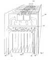
- FIG. 4is a side cutaway perspective view of the apparatus of FIG. 1 ;
- FIG. 5is a perspective view illustrating another embodiment of an apparatus with orthogonal modules
- FIGS. 6-7are additional perspective vies of the apparatus of FIG. 5 ;
- FIG. 8is a front perspective view illustrating yet another embodiment of an apparatus with orthogonal modules
- FIG. 9is a rear perspective view of the apparatus of FIG. 8 ;
- FIG. 10is a top perspective view of the apparatus of FIG. 8 ;
- FIG. 11is a side cutaway perspective of the apparatus of FIG. 8 .
- FIG. 1is a top perspective view illustrating an apparatus 100 with orthogonal modules according to one embodiment.
- the apparatus 100can be, for example, an enterprise class router, and the modules are typically circuit boards. But the disclosed technique can be used in any apparatus with orthogonal modules.
- the apparatus 100contains a plurality of modules 110 oriented vertically in a front section of the apparatus 100 and a plurality of modules 130 oriented in a horizontal direction in a rear section of the apparatus 100 . Modules 110 and 130 are cross-connected through a mid-plane 120 .
- the vertical modules 110are enclosed by an enclosure 170 on either side forming a plenum 150 on either side of the vertical modules 110 extending from the front of the apparatus 100 past the mid-plane 120 .
- barrier 160is placed between each of the modules 130 , forming a rear chamber of the apparatus 100 .
- barrier 160is a perforated rippled material where the perforation pattern can be figured to create a pressure difference between the front section on one side of the barrier 160 and the rear section on the other side of the barrier 160 . This pressure difference can achieve a more uniform air flow across more of the surface area of modules 130 .
- fans or blowers 140are placed at a rear portion of the modules 130 . The fans or blowers 140 pull air from the front of the apparatus 100 through the plenum 150 and through the barrier 160 across the modules 130 providing cooling to the modules 130 .
- Heated airis then exhausted through openings on the rear of the apparatus 100 as described below.
- two blowers 140are positioned centrally at the rear of each module 130 .
- a single fan or blower 140could be used.
- the fan or fans 140could be positioned in other locations on the modules 130 as desirable for uniform air flow across the surface of the modules 130 or to provide higher air flow across portions of the surface area of the modules 130 that generate proportionally more heat than other portions of the modules 130 .
- FIG. 2a front view of the apparatus 100 shows the plenums 150 on either side of the enclosure 170 surrounding the vertically oriented modules 110 . Additionally, FIG. 2 shows an independent cooling system for the modules 110 .
- a plenum 240is formed beneath the vertically oriented modules 110 and a lower fan tray 220 contains a plurality of fans that push air vertically across the surfaces of the modules 110 to provide cooling to the modules 110 .
- An upper fan tray 230contains a plurality of fans that pull heated air from the modules 110 and exhaust the heated air toward the rear of the apparatus 100 as described below.
- a plurality of power supplies 210are shown in FIG. 2 at the bottom of the apparatus 100 . In some embodiments, each of these power supply units provides its own front-to-back air cooling path from front openings or inlets in the power supply units 210 .
- FIG. 3a rear view in perspective of the apparatus 100 illustrates the outlets where heated air is exhausted to the rear of the apparatus 100 .
- a collection of power supply exhaust outlets 310correspond to the power supply inlets 210 of FIG. 2 .
- a pair of exhaust outlets 330is also shown for each of the modules 130 , corresponding to the two fans or blowers 140 illustrated in FIG. 1 .
- outlets 320provide exhaust outlets for heated air that have cooled the vertical modules 110 and is exhausted from the upper fan tray 230 .
- FIG. 4illustrates the air flow path across the vertical modules 110 .
- an upper plenum 410is formed above the upper fan tray 230 and the horizontally oriented modules 130 to provide an air path to the exhaust ports outlets 320 illustrated in FIG. 3 .
- apparatus 500pushes air across horizontal modules.
- One or more blowers or fans 510are positioned toward the front of the apparatus 500 in a plenum 520 .
- the fans 510push air through the plenum 520 formed along the side of vertical modules, not shown in FIG. 5 for clarity of the drawing.
- Putting the fans 510 in the plenum 520can allow for better filtering and cleaner air throughout the air path across the rear horizontally mounted modules than the negative pressure system illustrated in FIGS. 1-4 .
- filterscan be placed at the inlets of the plenum 520 in front of the fans 510 , but are not shown in FIG. 5 for clarity of the drawing.
- a barrier 530is placed at the outlets of the fans 510 . As best shown in FIG. 7 , openings 710 are formed in the barrier 530 to better control air flow through the plenum 520 . Air pushed through the plenum 520 is then pushed across the surfaces of the horizontal outlets 540 and exhausted through the rear of the apparatus 500 . As shown in FIGS. 5 and 6 , the apparatus 500 has a cooling system for the vertically oriented modules that is same as illustrated FIGS. 1-4 . The only difference between the embodiments of FIGS. 1-4 and FIGS. 5-7 is that instead of pulling the air through the plenum and across the cards as in FIGS.
- the apparatus 500pushes the air from the front through the plenum 520 and across the cards horizontal outlets 540 .
- the numbered configuration and placement of fans shown in FIGS. 5-7are exemplary and illustrative only and other numbers configuration and placement of fans can be used.
- the vertically oriented modules 110are in a front section of the apparatus 100 and horizontally mounted modules 130 are positioned in a rear section of the apparatus 100 .
- vertically oriented modulescan be placed in the rear, and horizontally oriented modules can be placed in the front of the apparatus.
- FIGS. 8-11illustrate such an apparatus according to one embodiment.
- FIG. 8a front perspective view illustrates an apparatus 800 that contains front mounted horizontal modules 810 .
- power supplies 830are cooled from air flow from the front.
- Inlets 820provide air to cool the rear mounted vertical modules of the apparatus 800 .
- Openings 840 in each of the horizontal modules 810provide an air path for cooling the horizontally mounted modules 810 .
- FIG. 9is a rear perspective view of the apparatus 800 of FIG. 8 .
- Vertically mounted modules 930are cooled by an upper fan tray 920 pulling air from inlets 820 of FIG. 8 , then pushing that air downward across the surfaces of the vertically mounted modules 930 .
- a lower fan tray 910contains exhaust fans that pull the heated air from the vertically oriented modules 930 , exhausting the heated air through plenums 960 formed below the lower fan tray to the rear of apparatus 800 .
- An end closure 940 holding the vertically oriented modules 930forms a plenum 950 on either side of the vertically oriented modules 930 to exhaust heated air from the horizontally oriented modules 810 .
- FIG. 10a top view shows the cooling path for the horizontal modules 810 . Cool air is pulled in through the openings 840 shown in FIG. 8 , and pulled across the surface of the modules 810 to a radial blower 1020 mounted on either side of each of the modules 810 . The radial blowers 1020 then exhaust the heated air through the plenums 950 to the rear of the apparatus 800 . As in the apparatus 100 of FIG. 1 , a mid-plane 1010 connects the horizontally mounted modules 810 and the vertically mounted modules 930 . Although described above as radial blowers, any desirable fan or blower can be used. The placement, configuration and number of blowers are exemplary and illustrative only, and other numbers configurations and placements can be used.
- FIG. 11a side view in perspective, shows the cooling path for the vertical rear modules 930 described above and the cooling path 1110 for power supplies at the bottom of the apparatus 800 .
- a plenum 1130provides air passage from the front of the apparatus 800 through inlets 820 to the upper fan tray 920 which then pushes air vertically downward across the surfaces of the modules 930 , where the lower fan tray 910 exhausts the air through plenum 960 to the rear of the apparatus 800 .
- a wall 1120provides a portion of an enclosure above the horizontally mounted modules 810 to form the plenum 1130 .
Landscapes
- Engineering & Computer Science (AREA)
- Aviation & Aerospace Engineering (AREA)
- Physics & Mathematics (AREA)
- Thermal Sciences (AREA)
- Microelectronics & Electronic Packaging (AREA)
- Cooling Or The Like Of Electrical Apparatus (AREA)
Abstract
Description
This application is a divisional of U.S. Ser. No. 12/167,604, filed on Jul. 3, 2008, entitled “FRONT-TO-BACK COOLING SYSTEM FOR MODULAR SYSTEMS WITH ORTHOGONAL MIDPLANE CONFIGURATION”, by Gunes Aybay, et al., currently pending.
Not applicable.
Not applicable.
The present invention relates to the field of cooling systems, and in particular to cooling of a modular system with orthogonal modules.
Systems that require very high bandwidth any-to-any connectivity among a set of modules typically use an orthogonal mid-plane configuration. In this configuration, a set of cards are plugged into the front side of the mid-plane in vertical configuration and another set of cards are plugged into the rear side of the mid-plane in horizontal configuration. This layout enables each front card to be directly connected to each rear card, and makes it possible to eliminate the use of PCB signal traces on the mid-plane to carry high speed signals.
However, the orthogonal configuration also creates a cooling challenge, especially in applications where front-to-back cooling is required. Vertical cards can be cooled using conventional cooling mechanisms with front air intake and rear air exhaust, but cooling the horizontal cards while maintaining overall front-to-back air flow is challenging.
If front-to-back cooling is not required, the horizontal card cage can be cooled using side-to-side air flow. However, many rack mount environments require front-to-back air cooling. One solution has been to divert air taken from a front intake to the back and run it up in a column next to the horizontal cards. Such a mechanism typically uses a set of fans or blowers to create the air pressure across the horizontal cards. However, the amount of air flow that is provided in such a system is typically limited due the number of turns in the air path. Also, the placement of one or two fan blades along the sides of the horizontal cards can severely limit the PCB area and panel surface that is available.
In one embodiment, a method of cooling an apparatus comprises: forming a plenum on a side of a first chamber of the apparatus, open to a front of the apparatus, partitioning the apparatus with an air-permeable barrier, forming a second chamber separated from the plenum and the first chamber by the air-permeable barrier, pulling air from the front of the apparatus via the plenum through the air-permeable barrier into the second chamber, and exhausting air from the second chamber to a rear of the apparatus.
In another embodiment, a method of cooling an apparatus comprises: cooling a first plurality of modules oriented in a first direction, comprising: pushing air from an edge of each of the first plurality of modules in the first direction, and pulling air from an opposite edge of each of the first plurality of modules in the first direction, and cooling a second plurality of modules oriented in a second direction, orthogonal to the first direction, comprising: moving air in the second direction across the second plurality of modules and through a plenum extending exterior to a first chamber containing the first plurality of modules, and exhausting air from the apparatus.
In yet another embodiment, a method of cooling an apparatus comprises: forming a plenum on a side of a first chamber containing a first plurality of modules, moving air from a front of the apparatus through the plenum into a second chamber containing a second plurality of modules, the second plurality of modules mounted orthogonal to the first plurality of modules, and exhausting air to a rear of the apparatus from the second chamber.
In yet another embodiment, a cooling system for an apparatus comprises: a first chamber, a plenum formed exterior to the first chamber and fluidly isolated from the first chamber, a second chamber in fluid communication with the plenum, a cooling system for the first chamber, comprising: a first fan, configured to push air across the first chamber, and a second fan, configured to pull air from the first chamber, and a cooling system for the second chamber, comprising: a third fan, configured to move air through the plenum into the second chamber.
In yet another embodiment, a method of cooling an apparatus comprises: forming a first plenum on a side of a first chamber containing a first plurality of modules, moving air from a front of the apparatus across a second plurality of modules, the second plurality of modules mounted orthogonal to the first plurality of modules in a second chamber, and exhausting air from the second plurality of modules through the first plenum to a rear of the apparatus.
The accompanying drawings, which are incorporated in and constitute a part of this specification, illustrate an implementation of apparatus and methods consistent with the present invention and, together with the detailed description, serve to explain advantages and principles consistent with the invention. In the drawings,
Turning toFIG. 2 , a front view of theapparatus 100 shows theplenums 150 on either side of theenclosure 170 surrounding the verticallyoriented modules 110. Additionally,FIG. 2 shows an independent cooling system for themodules 110. Aplenum 240 is formed beneath the verticallyoriented modules 110 and alower fan tray 220 contains a plurality of fans that push air vertically across the surfaces of themodules 110 to provide cooling to themodules 110. Anupper fan tray 230 contains a plurality of fans that pull heated air from themodules 110 and exhaust the heated air toward the rear of theapparatus 100 as described below. A plurality ofpower supplies 210 are shown inFIG. 2 at the bottom of theapparatus 100. In some embodiments, each of these power supply units provides its own front-to-back air cooling path from front openings or inlets in thepower supply units 210.
Turning toFIG. 3 , a rear view in perspective of theapparatus 100 illustrates the outlets where heated air is exhausted to the rear of theapparatus 100. A collection of powersupply exhaust outlets 310 correspond to thepower supply inlets 210 ofFIG. 2 . A pair ofexhaust outlets 330 is also shown for each of themodules 130, corresponding to the two fans or blowers140 illustrated inFIG. 1 . Finally,outlets 320 provide exhaust outlets for heated air that have cooled thevertical modules 110 and is exhausted from theupper fan tray 230.
In another embodiment, instead of pulling air from the front of theapparatus 100 across thehorizontal modules 130, as illustrated inFIG. 1 ,apparatus 500 pushes air across horizontal modules. One or more blowers orfans 510 are positioned toward the front of theapparatus 500 in aplenum 520. Thefans 510 push air through theplenum 520 formed along the side of vertical modules, not shown inFIG. 5 for clarity of the drawing. Putting thefans 510 in theplenum 520 can allow for better filtering and cleaner air throughout the air path across the rear horizontally mounted modules than the negative pressure system illustrated inFIGS. 1-4 . In some embodiments, filters can be placed at the inlets of theplenum 520 in front of thefans 510, but are not shown inFIG. 5 for clarity of the drawing. Abarrier 530 is placed at the outlets of thefans 510. As best shown inFIG. 7 ,openings 710 are formed in thebarrier 530 to better control air flow through theplenum 520. Air pushed through theplenum 520 is then pushed across the surfaces of thehorizontal outlets 540 and exhausted through the rear of theapparatus 500. As shown inFIGS. 5 and 6 , theapparatus 500 has a cooling system for the vertically oriented modules that is same as illustratedFIGS. 1-4 . The only difference between the embodiments ofFIGS. 1-4 andFIGS. 5-7 is that instead of pulling the air through the plenum and across the cards as inFIGS. 1-4 , theapparatus 500 pushes the air from the front through theplenum 520 and across the cardshorizontal outlets 540. The numbered configuration and placement of fans shown inFIGS. 5-7 are exemplary and illustrative only and other numbers configuration and placement of fans can be used.
Inapparatus 100, as illustrated inFIGS. 1-4 (and similarly inapparatus 500, illustrated inFIGS. 5-7 ), the vertically orientedmodules 110 are in a front section of theapparatus 100 and horizontally mountedmodules 130 are positioned in a rear section of theapparatus 100. In other embodiments, vertically oriented modules can be placed in the rear, and horizontally oriented modules can be placed in the front of the apparatus.FIGS. 8-11 illustrate such an apparatus according to one embodiment.
Turning now toFIG. 8 , a front perspective view illustrates anapparatus 800 that contains front mountedhorizontal modules 810. As withapparatus 100,power supplies 830 are cooled from air flow from the front.Inlets 820 provide air to cool the rear mounted vertical modules of theapparatus 800.Openings 840 in each of thehorizontal modules 810 provide an air path for cooling the horizontally mountedmodules 810.
Turning toFIG. 10 , a top view shows the cooling path for thehorizontal modules 810. Cool air is pulled in through theopenings 840 shown inFIG. 8 , and pulled across the surface of themodules 810 to aradial blower 1020 mounted on either side of each of themodules 810. Theradial blowers 1020 then exhaust the heated air through theplenums 950 to the rear of theapparatus 800. As in theapparatus 100 ofFIG. 1 , a mid-plane1010 connects the horizontally mountedmodules 810 and the vertically mountedmodules 930. Although described above as radial blowers, any desirable fan or blower can be used. The placement, configuration and number of blowers are exemplary and illustrative only, and other numbers configurations and placements can be used.
While certain exemplary embodiments have been described in details and shown in the accompanying drawings, it is to be understood that such embodiments are merely illustrative of and not devised without departing from the basic scope thereof, which is determined by the claims that follow. By way of example and not limitation, the specific electrical components utilized may be replaced by known equivalents or other arrangements of components which function similarly and provide substantially the same result.
Claims (20)
1. A method comprising:
moving air from a front of an apparatus through a first plenum into a second chamber, the first plenum being disposed on a side of a first chamber containing a first plurality of modules, the second chamber having a second plenum disposed above the second chamber, the second chamber containing a second plurality of modules; and
moving the air across the second plurality of modules, the second plurality of modules being mounted substantially orthogonal to the first plurality of modules; and
exhausting the air to a rear of the apparatus from the second chamber.
2. The method ofclaim 1 , wherein the moving air from the front of the apparatus through the first plenum into the second chamber further includes:
pulling the air from the front of the apparatus to a fan on a rear portion of each module from the second plurality of modules.
3. The method ofclaim 1 , wherein the moving air from the front of the apparatus through the first plenum into the second chamber further includes:
pushing air from a fan disposed within the first plenum to each module from the second plurality of modules.
4. The method ofclaim 1 , wherein the moving air from the front of the apparatus through the plenum into the second chamber further includes:
pulling the air from the front of the apparatus through an air-permeable barrier to a rear portion of each module from the second plurality of modules.
5. The method ofclaim 1 , further comprising:
moving air across the first plurality of modules through the second plenum.
6. The method ofclaim 1 , further comprising:
pushing air within the first chamber across the first plurality of modules;
pulling the air within the first chamber from the first plurality of modules; and
exhausting the air within the first chamber through the second plenum.
7. The method ofclaim 1 , further comprising:
pushing air from a front of the apparatus across the first plurality of modules;
pulling the air from the first plurality of modules; and
exhausting the air at pulled from the first plurality of modules to a rear of the apparatus.
8. An apparatus, comprising:
a housing defining a first chamber and a second chamber, the first chamber configured to receive a first plurality of modules, the second chamber configured to receive a second plurality of modules mounted substantially orthogonal to the first plurality of modules, the housing defining a first plenum on a side of the first chamber, the housing defining a second plenum above the second chamber; and a fan disposed within the housing, the fan configured to move air from a front of the housing through the first plenum into the second chamber and across the second plurality of modules.
9. The apparatus ofclaim 8 , wherein the fan is disposed within the first plenum, the apparatus further comprising:
an air-permeable barrier disposed within the first plenum along an air path between the fan and the second plurality of modules.
10. The apparatus ofclaim 8 , wherein the fan is a first fan, the apparatus further comprising:
a plurality of fans including the first fan, each fane from the plurality of being vertically disposed within the first plenum; and
an air-permeable barrier disposed within the first plenum along an air path between the fan and the second plurality of modules, the air-permeable barrier having a plurality of openings, each opening from the plurality of openings being uniquely associated with a fan from the plurality of fans.
11. The apparatus ofclaim 8 , wherein the fan is a first fan, the apparatus further comprising:
a second fan disposed within the housing, the second fan configured to move air across the first plurality of modules.
12. The apparatus ofclaim 8 , wherein the fan is a first fan, the apparatus further comprising:
a second fan disposed within the housing; and
a third fan disposed within the housing, the first plurality of modules being disposed between the second fan and the third fan,
the second fan and the third fan collectively configured to move air across the first plurality of modules.
13. The apparatus ofclaim 8 , wherein the fan is a first fan, the apparatus further comprising:
a second fan disposed within the housing, the second fan configured to push air across the first plurality of modules; and
a third fan disposed within the housing, the first plurality of modules being disposed between the second fan and the third fan, the third fan configured to pull air across the first plurality of modules.
14. An apparatus, comprising:
a housing defining a first chamber and a second chamber, the first chamber configured to receive a first plurality of modules, the second chamber configured to receive a second plurality of modules mounted substantially orthogonal to the first plurality of modules,
the housing defining a first plenum on a side of the first chamber, the housing defining a second plenum above the second chamber,
the housing defining an air flow path from a front of the housing through the first plenum into the second chamber and across the second plurality of modules.
15. The apparatus ofclaim 14 , wherein the air flow path is a first air flow path, the housing defines a second air flow path from the front of the housing into the first chamber and across the first plurality of modules.
16. The apparatus ofclaim 14 , further comprising:
a fan disposed within the first plenum; and
an air-permeable barrier disposed within the first plenum along the air flow path between the fan and the second plurality of modules.
17. The apparatus ofclaim 14 , further comprising:
a plurality of fans disposed within the first plenum; and
an air-permeable barrier disposed within the first plenum along the air flow path between the plurality of fans and the second plurality of modules, the air-permeable barrier having a plurality of openings, each opening from the plurality of openings being uniquely associated with a fan from the plurality of fans.
18. The apparatus ofclaim 14 , further comprising:
a first fan disposed within the first plenum; and
a second fan disposed within the housing, the second fan configured to move air across the first plurality of modules.
19. The apparatus ofclaim 14 , further comprising:
a first fan disposed within the first plenum;
a second fan disposed within the housing; and
a third fan disposed within the housing, the first plurality of modules being disposed between the second fan and the third fan,
the second fan and the third fan collectively configured to move air across the first plurality of modules.
20. The apparatus ofclaim 14 , further comprising:
a first fan disposed within the first plenum;
a second fan disposed within the housing, the second fan configured to push air across the first plurality of modules; and
a third fan disposed within the housing, the first plurality of modules being disposed between the second fan and the third fan, the third fan configured to pull air across the first plurality of modules.
Priority Applications (1)
| Application Number | Priority Date | Filing Date | Title |
|---|---|---|---|
| US12/889,075US8125779B2 (en) | 2008-07-03 | 2010-09-23 | Front-to-back cooling system for modular systems with orthogonal midplane configuration |
Applications Claiming Priority (2)
| Application Number | Priority Date | Filing Date | Title |
|---|---|---|---|
| US12/167,604US7826222B2 (en) | 2008-07-03 | 2008-07-03 | Front-to-back cooling system for modular systems with orthogonal midplane configuration |
| US12/889,075US8125779B2 (en) | 2008-07-03 | 2010-09-23 | Front-to-back cooling system for modular systems with orthogonal midplane configuration |
Related Parent Applications (1)
| Application Number | Title | Priority Date | Filing Date |
|---|---|---|---|
| US12/167,604DivisionUS7826222B2 (en) | 2008-07-03 | 2008-07-03 | Front-to-back cooling system for modular systems with orthogonal midplane configuration |
Publications (2)
| Publication Number | Publication Date |
|---|---|
| US20110011567A1 US20110011567A1 (en) | 2011-01-20 |
| US8125779B2true US8125779B2 (en) | 2012-02-28 |
Family
ID=41208645
Family Applications (4)
| Application Number | Title | Priority Date | Filing Date |
|---|---|---|---|
| US12/167,604Active2028-09-08US7826222B2 (en) | 2008-07-03 | 2008-07-03 | Front-to-back cooling system for modular systems with orthogonal midplane configuration |
| US12/889,039AbandonedUS20110056660A1 (en) | 2008-07-03 | 2010-09-23 | Front-to-back cooling system for modular systems with orthogonal midplane configuration |
| US12/889,075ActiveUS8125779B2 (en) | 2008-07-03 | 2010-09-23 | Front-to-back cooling system for modular systems with orthogonal midplane configuration |
| US12/889,111ActiveUS8120912B2 (en) | 2008-07-03 | 2010-09-23 | Front-to-back cooling system for modular systems with orthogonal midplane configuration |
Family Applications Before (2)
| Application Number | Title | Priority Date | Filing Date |
|---|---|---|---|
| US12/167,604Active2028-09-08US7826222B2 (en) | 2008-07-03 | 2008-07-03 | Front-to-back cooling system for modular systems with orthogonal midplane configuration |
| US12/889,039AbandonedUS20110056660A1 (en) | 2008-07-03 | 2010-09-23 | Front-to-back cooling system for modular systems with orthogonal midplane configuration |
Family Applications After (1)
| Application Number | Title | Priority Date | Filing Date |
|---|---|---|---|
| US12/889,111ActiveUS8120912B2 (en) | 2008-07-03 | 2010-09-23 | Front-to-back cooling system for modular systems with orthogonal midplane configuration |
Country Status (3)
| Country | Link |
|---|---|
| US (4) | US7826222B2 (en) |
| EP (2) | EP2141974B1 (en) |
| CN (2) | CN101621913B (en) |
Cited By (11)
| Publication number | Priority date | Publication date | Assignee | Title |
|---|---|---|---|---|
| US20120045982A1 (en)* | 2010-08-18 | 2012-02-23 | Hon Hai Precision Industry Co., Ltd. | Container data center |
| US8238094B1 (en)* | 2008-12-22 | 2012-08-07 | Juniper Networks, Inc. | Cooling system for a data processing unit |
| US20120327597A1 (en)* | 2011-06-27 | 2012-12-27 | Futurewei Technologies, Inc. | Hybrid Cooling Design for Modular Systems |
| US20120327599A1 (en)* | 2011-06-27 | 2012-12-27 | DICKINSON Roger | Cooling Module with Parallel Blowers |
| US8534930B1 (en) | 2009-09-24 | 2013-09-17 | Juniper Networks, Inc. | Circuit boards defining openings for cooling electronic devices |
| US8801374B1 (en) | 2009-10-07 | 2014-08-12 | Juniper Networks, Inc. | Fan trays having stator blades for improving air flow performance |
| US9039432B2 (en) | 2011-07-08 | 2015-05-26 | Cisco Technology, Inc. | System and method for high connectivity platform |
| US9253928B2 (en) | 2011-06-27 | 2016-02-02 | Henkel IP & Holding GmbH | Cooling module with parallel blowers |
| US9560793B2 (en) | 2012-04-27 | 2017-01-31 | Hewlett Packard Enterprise Development Lp | Blade enclosure |
| US20170131750A1 (en)* | 2015-11-10 | 2017-05-11 | Fujitsu Limited | Cooling device and information processing apparatus |
| US9811969B2 (en) | 2015-03-30 | 2017-11-07 | Bally Gaming, Inc. | Removable fan assembly providing multi-directional air flow for a wagering game machine |
Families Citing this family (88)
| Publication number | Priority date | Publication date | Assignee | Title |
|---|---|---|---|---|
| US8064200B1 (en)* | 2008-04-16 | 2011-11-22 | Cyan Optics, Inc. | Cooling a chassis by moving air through a midplane between two sets of channels oriented laterally relative to one another |
| US10058011B2 (en)* | 2008-06-19 | 2018-08-21 | Panduit Corp. | Passive cooling systems for network cabinet |
| US7826222B2 (en)* | 2008-07-03 | 2010-11-02 | Juniper Networks, Inc. | Front-to-back cooling system for modular systems with orthogonal midplane configuration |
| US8798045B1 (en) | 2008-12-29 | 2014-08-05 | Juniper Networks, Inc. | Control plane architecture for switch fabrics |
| US8535787B1 (en) | 2009-06-29 | 2013-09-17 | Juniper Networks, Inc. | Heat sinks having a thermal interface for cooling electronic devices |
| US8705500B1 (en) | 2009-11-05 | 2014-04-22 | Juniper Networks, Inc. | Methods and apparatus for upgrading a switch fabric |
| US8223498B2 (en) | 2009-11-11 | 2012-07-17 | Juniper Networks, Inc. | Thermal interface members for removable electronic devices |
| KR101712100B1 (en)* | 2010-01-12 | 2017-03-03 | 삼성전자 주식회사 | Cooling system and display apparatus using the same |
| US8279601B2 (en)* | 2010-01-28 | 2012-10-02 | Juniper Networks, Inc. | Air flow ducts for cooling electronic devices within a data processing unit |
| US9240923B2 (en)* | 2010-03-23 | 2016-01-19 | Juniper Networks, Inc. | Methods and apparatus for automatically provisioning resources within a distributed control plane of a switch |
| US9270486B2 (en) | 2010-06-07 | 2016-02-23 | Brocade Communications Systems, Inc. | Name services for virtual cluster switching |
| US9716672B2 (en) | 2010-05-28 | 2017-07-25 | Brocade Communications Systems, Inc. | Distributed configuration management for virtual cluster switching |
| US9769016B2 (en) | 2010-06-07 | 2017-09-19 | Brocade Communications Systems, Inc. | Advanced link tracking for virtual cluster switching |
| US8867552B2 (en) | 2010-05-03 | 2014-10-21 | Brocade Communications Systems, Inc. | Virtual cluster switching |
| DE202010007046U1 (en)* | 2010-05-20 | 2010-08-26 | Fujitsu Technology Solutions Intellectual Property Gmbh | Rack housing for receiving a plurality of fanless insertion components |
| US9628293B2 (en) | 2010-06-08 | 2017-04-18 | Brocade Communications Systems, Inc. | Network layer multicasting in trill networks |
| US9608833B2 (en) | 2010-06-08 | 2017-03-28 | Brocade Communications Systems, Inc. | Supporting multiple multicast trees in trill networks |
| US9806906B2 (en) | 2010-06-08 | 2017-10-31 | Brocade Communications Systems, Inc. | Flooding packets on a per-virtual-network basis |
| US9807031B2 (en) | 2010-07-16 | 2017-10-31 | Brocade Communications Systems, Inc. | System and method for network configuration |
| US8718063B2 (en) | 2010-07-26 | 2014-05-06 | Juniper Networks, Inc. | Methods and apparatus related to route selection within a network |
| JP5315323B2 (en)* | 2010-11-17 | 2013-10-16 | アラクサラネットワークス株式会社 | Electronic equipment |
| US8560660B2 (en) | 2010-12-15 | 2013-10-15 | Juniper Networks, Inc. | Methods and apparatus for managing next hop identifiers in a distributed switch fabric system |
| US9282060B2 (en) | 2010-12-15 | 2016-03-08 | Juniper Networks, Inc. | Methods and apparatus for dynamic resource management within a distributed control plane of a switch |
| US9391796B1 (en) | 2010-12-22 | 2016-07-12 | Juniper Networks, Inc. | Methods and apparatus for using border gateway protocol (BGP) for converged fibre channel (FC) control plane |
| US9106527B1 (en) | 2010-12-22 | 2015-08-11 | Juniper Networks, Inc. | Hierarchical resource groups for providing segregated management access to a distributed switch |
| US9736085B2 (en) | 2011-08-29 | 2017-08-15 | Brocade Communications Systems, Inc. | End-to end lossless Ethernet in Ethernet fabric |
| CN102510707B (en) | 2011-11-01 | 2014-08-13 | 华为技术有限公司 | Cooling system and electronic device with same |
| US9699117B2 (en) | 2011-11-08 | 2017-07-04 | Brocade Communications Systems, Inc. | Integrated fibre channel support in an ethernet fabric switch |
| US9450870B2 (en) | 2011-11-10 | 2016-09-20 | Brocade Communications Systems, Inc. | System and method for flow management in software-defined networks |
| US9531644B2 (en) | 2011-12-21 | 2016-12-27 | Juniper Networks, Inc. | Methods and apparatus for a distributed fibre channel control plane |
| JP5927911B2 (en)* | 2011-12-28 | 2016-06-01 | 富士通株式会社 | COOLING UNIT, COOLING UNIT CASES, AND ELECTRONIC DEVICE |
| US9742693B2 (en) | 2012-02-27 | 2017-08-22 | Brocade Communications Systems, Inc. | Dynamic service insertion in a fabric switch |
| US9154416B2 (en) | 2012-03-22 | 2015-10-06 | Brocade Communications Systems, Inc. | Overlay tunnel in a fabric switch |
| EP2645836A1 (en)* | 2012-03-30 | 2013-10-02 | Alcatel Lucent | Mounting arrangement for orthogonally mounting plug-in cards |
| US8693195B2 (en) | 2012-05-01 | 2014-04-08 | Hewlett-Packard Development Company, L.P. | Chassis apparatus protruding electronic devices |
| US10277464B2 (en) | 2012-05-22 | 2019-04-30 | Arris Enterprises Llc | Client auto-configuration in a multi-switch link aggregation |
| US9461768B2 (en)* | 2012-05-23 | 2016-10-04 | Brocade Communications Systems, Inc. | Terabit top-of-rack switch |
| US9148975B2 (en)* | 2012-06-22 | 2015-09-29 | Advanced Micro Devices, Inc. | Electronic interconnect method and apparatus |
| US8885341B2 (en) | 2012-08-28 | 2014-11-11 | Motorola Mobility Llc | Compact front to back horizontal cooling for rack mounted chassis |
| JP5829992B2 (en)* | 2012-09-27 | 2015-12-09 | 東芝三菱電機産業システム株式会社 | Electrical equipment storage device |
| US8922992B2 (en)* | 2012-11-12 | 2014-12-30 | Dell Products L.P. | System and design of cost effective chassis design for networking products |
| US9215831B2 (en) | 2012-11-22 | 2015-12-15 | Huawei Technologies Co., Ltd. | Heat dissipation system |
| CN103841792B (en)* | 2012-11-22 | 2017-04-12 | 华为技术有限公司 | Cooling system |
| US9413691B2 (en) | 2013-01-11 | 2016-08-09 | Brocade Communications Systems, Inc. | MAC address synchronization in a fabric switch |
| US9548926B2 (en) | 2013-01-11 | 2017-01-17 | Brocade Communications Systems, Inc. | Multicast traffic load balancing over virtual link aggregation |
| US9565099B2 (en) | 2013-03-01 | 2017-02-07 | Brocade Communications Systems, Inc. | Spanning tree in fabric switches |
| CN203423892U (en)* | 2013-05-23 | 2014-02-05 | 杭州华三通信技术有限公司 | Electronic device |
| US9912612B2 (en) | 2013-10-28 | 2018-03-06 | Brocade Communications Systems LLC | Extended ethernet fabric switches |
| CN203691803U (en)* | 2013-12-27 | 2014-07-02 | 中兴通讯股份有限公司 | Plug-in box and terminal |
| US9548873B2 (en) | 2014-02-10 | 2017-01-17 | Brocade Communications Systems, Inc. | Virtual extensible LAN tunnel keepalives |
| US10581758B2 (en) | 2014-03-19 | 2020-03-03 | Avago Technologies International Sales Pte. Limited | Distributed hot standby links for vLAG |
| US10476698B2 (en) | 2014-03-20 | 2019-11-12 | Avago Technologies International Sales Pte. Limited | Redundent virtual link aggregation group |
| US10063473B2 (en) | 2014-04-30 | 2018-08-28 | Brocade Communications Systems LLC | Method and system for facilitating switch virtualization in a network of interconnected switches |
| US9800471B2 (en) | 2014-05-13 | 2017-10-24 | Brocade Communications Systems, Inc. | Network extension groups of global VLANs in a fabric switch |
| US9603280B2 (en) | 2014-05-30 | 2017-03-21 | EMC IP Holding Company LLC | Flash module |
| US9398720B1 (en)* | 2014-05-30 | 2016-07-19 | Emc Corporation | Chassis with airflow and thermal management |
| US9362641B2 (en) | 2014-07-01 | 2016-06-07 | Telefonaktiebolaget L M Ericsson (Publ) | Orthogonal backplane design with reduced chassis depth |
| US10616108B2 (en) | 2014-07-29 | 2020-04-07 | Avago Technologies International Sales Pte. Limited | Scalable MAC address virtualization |
| US9807007B2 (en) | 2014-08-11 | 2017-10-31 | Brocade Communications Systems, Inc. | Progressive MAC address learning |
| US9699029B2 (en) | 2014-10-10 | 2017-07-04 | Brocade Communications Systems, Inc. | Distributed configuration management in a switch group |
| CN105592667A (en)* | 2014-10-24 | 2016-05-18 | 华为技术有限公司 | Network device |
| US9628407B2 (en) | 2014-12-31 | 2017-04-18 | Brocade Communications Systems, Inc. | Multiple software versions in a switch group |
| US9626255B2 (en) | 2014-12-31 | 2017-04-18 | Brocade Communications Systems, Inc. | Online restoration of a switch snapshot |
| US9942097B2 (en) | 2015-01-05 | 2018-04-10 | Brocade Communications Systems LLC | Power management in a network of interconnected switches |
| US10003552B2 (en) | 2015-01-05 | 2018-06-19 | Brocade Communications Systems, Llc. | Distributed bidirectional forwarding detection protocol (D-BFD) for cluster of interconnected switches |
| US10038592B2 (en) | 2015-03-17 | 2018-07-31 | Brocade Communications Systems LLC | Identifier assignment to a new switch in a switch group |
| US9807005B2 (en) | 2015-03-17 | 2017-10-31 | Brocade Communications Systems, Inc. | Multi-fabric manager |
| US10579406B2 (en) | 2015-04-08 | 2020-03-03 | Avago Technologies International Sales Pte. Limited | Dynamic orchestration of overlay tunnels |
| WO2016175834A1 (en)* | 2015-04-30 | 2016-11-03 | Hewlett Packard Enterprise Development Lp | Cooling via a sleeve connector |
| US10439929B2 (en) | 2015-07-31 | 2019-10-08 | Avago Technologies International Sales Pte. Limited | Graceful recovery of a multicast-enabled switch |
| US10171303B2 (en) | 2015-09-16 | 2019-01-01 | Avago Technologies International Sales Pte. Limited | IP-based interconnection of switches with a logical chassis |
| US10299403B2 (en)* | 2015-09-23 | 2019-05-21 | Advanced Micro Devices, Inc. | Modular thermal solution for high-performance processors |
| US9912614B2 (en) | 2015-12-07 | 2018-03-06 | Brocade Communications Systems LLC | Interconnection of switches based on hierarchical overlay tunneling |
| MY178128A (en)* | 2016-01-07 | 2020-10-05 | Nokia Technologies Oy | Method of indication of available radio resources |
| US10365378B2 (en)* | 2016-02-29 | 2019-07-30 | Thermo Eberline Llc | Active dosimeter systems for real-time radiation dose measurements |
| KR102104383B1 (en)* | 2016-04-25 | 2020-04-24 | 주식회사 엘지화학 | Energy storage apparatus and method for cooling the energy storage apparatus |
| US9510486B1 (en) | 2016-07-13 | 2016-11-29 | Matteo B. Gravina | Data center cooling system having electrical power generation |
| US10237090B2 (en) | 2016-10-28 | 2019-03-19 | Avago Technologies International Sales Pte. Limited | Rule-based network identifier mapping |
| US9907213B1 (en) | 2016-12-12 | 2018-02-27 | Matteo B. Gravina | Data center cooling system having electrical power generation |
| US10020436B1 (en) | 2017-06-15 | 2018-07-10 | Matteo B. Gravina | Thermal energy accumulator for power generation and high performance computing center |
| CN107708379A (en)* | 2017-09-18 | 2018-02-16 | 北京百卓网络技术有限公司 | A kind of service card and communication equipment |
| CN107613728A (en)* | 2017-09-18 | 2018-01-19 | 北京百卓网络技术有限公司 | A kind of communication equipment with rear plug-in card and thereafter plug-in card |
| CN108235637B (en)* | 2017-12-15 | 2020-08-21 | 深圳市恒扬数据股份有限公司 | Vertical orthogonal system for communication equipment and communication equipment |
| US11096314B2 (en) | 2018-07-09 | 2021-08-17 | Cisco Technology, Inc. | Front accessible fan tray with front-to-back cooling in a modular electronic system |
| US10912216B1 (en) | 2018-09-26 | 2021-02-02 | Cisco Technology, Inc. | Bidirectional installation module for modular electronic system |
| KR102767456B1 (en)* | 2018-11-05 | 2025-02-17 | 삼성전자주식회사 | Solid state drive device and computer server system having the same |
| CN113821383A (en)* | 2020-06-19 | 2021-12-21 | 华为技术有限公司 | Storage system |
| WO2022192376A1 (en)* | 2021-03-11 | 2022-09-15 | Core Scientific, Inc. | System for cooling computing devices in an array |
Citations (82)
| Publication number | Priority date | Publication date | Assignee | Title |
|---|---|---|---|---|
| US3895215A (en) | 1973-11-23 | 1975-07-15 | Jerry Dale Gordon | Cabinet for holding food at a controllable temperature |
| US4971143A (en) | 1989-05-22 | 1990-11-20 | Carrier Corporation | Fan stator assembly for heat exchanger |
| US5477416A (en) | 1995-02-14 | 1995-12-19 | Hewlett-Packard Company | Enclosure with metered air ducts for mounting and cooling modules |
| US5663868A (en) | 1994-09-14 | 1997-09-02 | Questech Limited | Stackable electronic equipment assembly with improved circuit board cooling arrangement |
| US5751549A (en) | 1996-06-26 | 1998-05-12 | Sun Microsystems, Inc. | Hard disk drive assembly which has a plenum chamber and a fan assembly that is perpendicular to a rack chamber |
| US5758413A (en) | 1995-09-25 | 1998-06-02 | International Business Machines Corporation | Method of manufacturing a multiple layer circuit board die carrier with fine dimension stacked vias |
| US5912801A (en) | 1997-09-16 | 1999-06-15 | Excel, Inc. | Telecommunication switch chassis |
| US6163454A (en) | 1999-02-22 | 2000-12-19 | Hewlett-Packard Company | Electromagnetic interference (EMI) shield for electrical components, an internal EMI barrier, and a storage enclosure for electrical/electronic components |
| US6280318B1 (en) | 2000-02-22 | 2001-08-28 | International Game Technology | Central forced air cooling of a gaming machine |
| US6293753B1 (en) | 2000-03-03 | 2001-09-25 | Motorola | Air moving apparatus and method of optimizing performance thereof |
| US6332758B1 (en) | 2000-01-25 | 2001-12-25 | Hsin-Mao Hsieh | Air-bearing fan |
| US20020018339A1 (en)* | 2000-08-14 | 2002-02-14 | Yoshinori Uzuka | Information-processing device having a crossbar-board connected to back panels on different sides |
| US6372997B1 (en) | 2000-02-25 | 2002-04-16 | Thermagon, Inc. | Multi-layer structure and method for forming a thermal interface with low contact resistance between a microelectronic component package and heat sink |
| US6449150B1 (en) | 2000-11-13 | 2002-09-10 | Cisco Technology, Inc. | Method and system for cooling a card shelf |
| US20020126449A1 (en) | 2001-03-12 | 2002-09-12 | Casebolt Matthew P. | Low profile highly accessible computer enclosure with plenum for cooling high power processors |
| US6452797B1 (en) | 1997-11-12 | 2002-09-17 | Intel Corporation | Fan-cooled card |
| US6462948B1 (en) | 2001-06-25 | 2002-10-08 | Intel Corporation | Thermal management system for a multiple processor computer appliance |
| US6508621B1 (en) | 2001-07-26 | 2003-01-21 | Hewlett-Packard Company | Enhanced performance air moving assembly |
| US6508595B1 (en) | 2000-05-11 | 2003-01-21 | International Business Machines Corporation | Assembly of opto-electronic module with improved heat sink |
| US6549406B1 (en) | 2002-05-09 | 2003-04-15 | Sun Microsystems, Inc. | Fan tray assembly for an electronics enclosure |
| US6565334B1 (en) | 1998-07-20 | 2003-05-20 | Phillip James Bradbury | Axial flow fan having counter-rotating dual impeller blade arrangement |
| US6603662B1 (en) | 2002-01-25 | 2003-08-05 | Sun Microsystems, Inc. | Computer cooling system |
| US6628520B2 (en) | 2002-02-06 | 2003-09-30 | Hewlett-Packard Development Company, L.P. | Method, apparatus, and system for cooling electronic components |
| US6653755B2 (en) | 2001-05-30 | 2003-11-25 | Intel Corporation | Radial air flow fan assembly having stator fins surrounding rotor blades |
| US20040001311A1 (en) | 2002-06-28 | 2004-01-01 | Doblar Drew G. | Computer system employing redundant cooling fans |
| US6721180B2 (en) | 2002-07-31 | 2004-04-13 | Infineon Technologies Ag | Cooling hood for circuit board |
| US6729905B1 (en) | 2003-03-12 | 2004-05-04 | Hon Hai Precision Ind. Co., Ltd. | Transceiver cage assembly |
| US6755242B2 (en) | 2001-04-17 | 2004-06-29 | Hewlett-Packard Development Company, L.P. | Active heat sink structure with directed air flow |
| US20040130868A1 (en) | 2003-01-08 | 2004-07-08 | Schwartz William H. | Cooling system including redundant fan controllers |
| US6778386B2 (en) | 2001-08-10 | 2004-08-17 | Sun Microsystems, Inc. | Cooling computer systems |
| US6835453B2 (en) | 2001-01-22 | 2004-12-28 | Parker-Hannifin Corporation | Clean release, phase change thermal interface |
| US20040264145A1 (en) | 2003-05-08 | 2004-12-30 | Miller Greg F. | Compact electronic component system and method |
| US6876549B2 (en)* | 2001-09-14 | 2005-04-05 | Hewlett-Packard Development Company, L.P. | Method and apparatus for individually cooling components of electronic systems |
| US6879486B1 (en) | 2002-02-14 | 2005-04-12 | Mercury Computer Systems, Inc. | Central inlet circuit board assembly |
| US6900387B2 (en) | 2002-01-30 | 2005-05-31 | Sun Microsystems, Inc. | Balanced flow cooling |
| US6912131B2 (en) | 2003-08-27 | 2005-06-28 | Lucent Technologies Inc. | Electronic components card air deflector |
| US20050180103A1 (en) | 2004-02-13 | 2005-08-18 | Ku Hung C. | Electrical apparatus and heat sink device thereof |
| US20050207134A1 (en) | 2004-03-16 | 2005-09-22 | Belady Christian L | Cell board interconnection architecture |
| US20050281005A1 (en) | 2004-06-21 | 2005-12-22 | Carullo Thomas J | Modular chassis divided along a midplane and cooling system therefor |
| US6980437B2 (en) | 2004-03-03 | 2005-12-27 | Tyco Electronics Corporation | Pluggable electronic receptacle with heat sink assembly |
| US20060002084A1 (en) | 2004-06-30 | 2006-01-05 | Wen Wei | Telecom equipment chassis using modular air cooling system |
| US6986679B1 (en) | 2002-09-14 | 2006-01-17 | Finisar Corporation | Transceiver module cage for use with modules of varying widths |
| US7011504B2 (en) | 2003-04-04 | 2006-03-14 | Nidec America Corporation | Fan, fan guard and related method |
| US20060126292A1 (en)* | 2004-12-14 | 2006-06-15 | Pfahnl Andreas C | Air cooling architecture for orthogonal board architectures |
| US7074123B2 (en) | 2004-01-13 | 2006-07-11 | Power Of 4, L.L.C. | Cabinet for computer devices with air distribution device |
| US7088583B2 (en) | 2004-10-25 | 2006-08-08 | International Business Machines Corporation | System for airflow management in electronic enclosures |
| US7112131B2 (en) | 2003-05-13 | 2006-09-26 | American Power Conversion Corporation | Rack enclosure |
| US7145773B2 (en) | 2004-02-26 | 2006-12-05 | Nortel Networks Limited | Pluggable electronic module |
| US7151229B2 (en) | 2003-05-13 | 2006-12-19 | Agilent Technologies, Inc. | Printed circuit board with improved cooling of electrical component |
| US7154748B2 (en) | 2003-02-20 | 2006-12-26 | Fujitsu Limited | Cooling structure of electronic equipment and information processing equipment using the cooling structure |
| US7158379B2 (en) | 2003-12-12 | 2007-01-02 | Cisco Technology, Inc. | Device for removing heat from a power connector |
| US7184268B2 (en) | 2005-01-10 | 2007-02-27 | Hewlett-Packard Development Company, L.P. | Dynamically adaptable electronics cooling fan |
| US7224582B1 (en) | 2004-09-20 | 2007-05-29 | Nortel Networks Limited | Floating heatsink for removable components |
| US7239515B2 (en) | 2004-03-08 | 2007-07-03 | Nortel Networks Limited | Thermal assembly for cooling an electronics module |
| US20070153462A1 (en) | 2005-12-30 | 2007-07-05 | International Business Machines Corporation | Midplane connector for blades |
| US7241110B2 (en) | 2003-10-31 | 2007-07-10 | Delta Electronics, Inc. | Centrifugal fan with stator blades |
| US7256995B2 (en) | 2002-06-10 | 2007-08-14 | Sun Microsystems, Inc. | Electronics module |
| US20070223199A1 (en) | 2006-03-24 | 2007-09-27 | Fujitsu Limited | Electronic apparatus |
| US7329091B2 (en) | 2004-08-18 | 2008-02-12 | Delta Electronics, Inc. | Heat dissipation fans and housings therefor |
| US7369411B2 (en) | 2000-02-25 | 2008-05-06 | Thermagon, Inc. | Thermal interface assembly and method for forming a thermal interface between a microelectronic component package and heat sink |
| US7371965B2 (en) | 2002-05-09 | 2008-05-13 | Finisar Corporation | Modular cage with heat sink for use with pluggable module |
| US7420806B1 (en) | 2005-11-22 | 2008-09-02 | Juniper Networks, Inc. | Airflow distribution through an electronic device |
| US20080225479A1 (en) | 2006-10-19 | 2008-09-18 | Cisco Technology, Inc. | Method and apparatus for providing thermal management in an electronic device |
| US20080232067A1 (en) | 2007-03-23 | 2008-09-25 | Finisar Corporation | Mechanisms for heat transfer in an optical transceiver module and card cage system |
| US7434412B1 (en) | 2005-10-27 | 2008-10-14 | Sun Microsystems, Inc. | Computer equipment temperature control system and methods for operating the same |
| US20080271875A1 (en) | 2006-04-28 | 2008-11-06 | Juniper Networks, Inc. | Re-workable heat sink attachment assembly |
| US20090059520A1 (en) | 2007-08-28 | 2009-03-05 | Hitachi, Ltd. | Cooling structure for rackmount-type control device and rack-type storage control device |
| US20090101274A1 (en) | 2002-06-27 | 2009-04-23 | Olson Kevin C | Single or Multi-Layer Printed Circuit Board With Improved Via Design |
| US20090109612A1 (en) | 2007-10-29 | 2009-04-30 | Dell Products L.P. | Chassis Having a Bypass Channel for Air Flow |
| US20090116185A1 (en) | 2007-11-02 | 2009-05-07 | Hou-An Su | Small form-factor pluggable transceiver module housing |
| US20090122484A1 (en) | 2007-11-09 | 2009-05-14 | Panduit Corp. | Cooling System |
| US7548421B2 (en) | 2005-10-25 | 2009-06-16 | Hewlett-Packard Development Company, L.P. | Impingement cooling of components in an electronic system |
| US20090166854A1 (en) | 2007-12-26 | 2009-07-02 | Radesh Jewram | Thermal Interface with Non-Tacky Surface |
| US20090296352A1 (en) | 2006-02-28 | 2009-12-03 | Lima David J | Thermal management of electronic devices |
| EP2141974A2 (en) | 2008-07-03 | 2010-01-06 | Juniper Networks, Inc. | Front-to-back cooling system for modular systems with orthogonal midplane configuration |
| US20100014248A1 (en) | 2008-07-17 | 2010-01-21 | Juniper Networks, Inc. | Airflow/cooling solution for chassis with orthogonal boards |
| US7722359B1 (en)* | 2007-09-27 | 2010-05-25 | Emc Corporation | Connection assembly having midplane with enhanced connection and airflow features |
| US7804684B1 (en)* | 2008-12-22 | 2010-09-28 | Juniper Networks, Inc. | Cooling system for a data processing unit |
| US7808792B2 (en)* | 2007-12-18 | 2010-10-05 | Juniper Networks, Inc. | Single fan tray in a midplane architecture |
| US7813120B2 (en) | 2007-06-13 | 2010-10-12 | Hewlett-Packard Development Company, L.P. | Airflow path within an electronic module enclosure |
| US20110110048A1 (en) | 2009-11-11 | 2011-05-12 | Lima David J | Thermal interface members for removable electronic devices |
| US20110182027A1 (en) | 2010-01-28 | 2011-07-28 | Lima David J | Air flow ducts for cooling electronic devices within a data processing unit |
Family Cites Families (5)
| Publication number | Priority date | Publication date | Assignee | Title |
|---|---|---|---|---|
| US5079438A (en)* | 1989-01-30 | 1992-01-07 | Heung Lap Yan | Circuit module fan assembly |
| AU2004291570A1 (en)* | 2003-11-18 | 2005-06-02 | Distributed Thermal Systems Ltd. | Series fans with flow modification element |
| JP4312235B2 (en)* | 2004-11-16 | 2009-08-12 | 富士通株式会社 | Communication device and rack structure |
| SE527918C2 (en)* | 2004-12-22 | 2006-07-11 | Dometic Sweden Ab | Apparatus box for computer and computer including such apparatus box |
| US8064200B1 (en)* | 2008-04-16 | 2011-11-22 | Cyan Optics, Inc. | Cooling a chassis by moving air through a midplane between two sets of channels oriented laterally relative to one another |
- 2008
- 2008-07-03USUS12/167,604patent/US7826222B2/enactiveActive
- 2008-08-27CNCN200810210571.2Apatent/CN101621913B/enactiveActive
- 2008-08-27CNCN201410456757.1Apatent/CN104284565B/enactiveActive
- 2008-08-28EPEP08252855.5Apatent/EP2141974B1/enactiveActive
- 2008-08-28EPEP14151003.2Apatent/EP2720524B1/enactiveActive
- 2010
- 2010-09-23USUS12/889,039patent/US20110056660A1/ennot_activeAbandoned
- 2010-09-23USUS12/889,075patent/US8125779B2/enactiveActive
- 2010-09-23USUS12/889,111patent/US8120912B2/enactiveActive
Patent Citations (95)
| Publication number | Priority date | Publication date | Assignee | Title |
|---|---|---|---|---|
| US3895215A (en) | 1973-11-23 | 1975-07-15 | Jerry Dale Gordon | Cabinet for holding food at a controllable temperature |
| US4971143A (en) | 1989-05-22 | 1990-11-20 | Carrier Corporation | Fan stator assembly for heat exchanger |
| US5663868A (en) | 1994-09-14 | 1997-09-02 | Questech Limited | Stackable electronic equipment assembly with improved circuit board cooling arrangement |
| US5477416A (en) | 1995-02-14 | 1995-12-19 | Hewlett-Packard Company | Enclosure with metered air ducts for mounting and cooling modules |
| US5758413A (en) | 1995-09-25 | 1998-06-02 | International Business Machines Corporation | Method of manufacturing a multiple layer circuit board die carrier with fine dimension stacked vias |
| US5751549A (en) | 1996-06-26 | 1998-05-12 | Sun Microsystems, Inc. | Hard disk drive assembly which has a plenum chamber and a fan assembly that is perpendicular to a rack chamber |
| US5912801A (en) | 1997-09-16 | 1999-06-15 | Excel, Inc. | Telecommunication switch chassis |
| US6452797B1 (en) | 1997-11-12 | 2002-09-17 | Intel Corporation | Fan-cooled card |
| US6565334B1 (en) | 1998-07-20 | 2003-05-20 | Phillip James Bradbury | Axial flow fan having counter-rotating dual impeller blade arrangement |
| US6163454A (en) | 1999-02-22 | 2000-12-19 | Hewlett-Packard Company | Electromagnetic interference (EMI) shield for electrical components, an internal EMI barrier, and a storage enclosure for electrical/electronic components |
| US6332758B1 (en) | 2000-01-25 | 2001-12-25 | Hsin-Mao Hsieh | Air-bearing fan |
| US6280318B1 (en) | 2000-02-22 | 2001-08-28 | International Game Technology | Central forced air cooling of a gaming machine |
| US6372997B1 (en) | 2000-02-25 | 2002-04-16 | Thermagon, Inc. | Multi-layer structure and method for forming a thermal interface with low contact resistance between a microelectronic component package and heat sink |
| US7369411B2 (en) | 2000-02-25 | 2008-05-06 | Thermagon, Inc. | Thermal interface assembly and method for forming a thermal interface between a microelectronic component package and heat sink |
| US6293753B1 (en) | 2000-03-03 | 2001-09-25 | Motorola | Air moving apparatus and method of optimizing performance thereof |
| US6508595B1 (en) | 2000-05-11 | 2003-01-21 | International Business Machines Corporation | Assembly of opto-electronic module with improved heat sink |
| US20020018339A1 (en)* | 2000-08-14 | 2002-02-14 | Yoshinori Uzuka | Information-processing device having a crossbar-board connected to back panels on different sides |
| US6449150B1 (en) | 2000-11-13 | 2002-09-10 | Cisco Technology, Inc. | Method and system for cooling a card shelf |
| US6835453B2 (en) | 2001-01-22 | 2004-12-28 | Parker-Hannifin Corporation | Clean release, phase change thermal interface |
| US20020126449A1 (en) | 2001-03-12 | 2002-09-12 | Casebolt Matthew P. | Low profile highly accessible computer enclosure with plenum for cooling high power processors |
| US6755242B2 (en) | 2001-04-17 | 2004-06-29 | Hewlett-Packard Development Company, L.P. | Active heat sink structure with directed air flow |
| US6653755B2 (en) | 2001-05-30 | 2003-11-25 | Intel Corporation | Radial air flow fan assembly having stator fins surrounding rotor blades |
| US6462948B1 (en) | 2001-06-25 | 2002-10-08 | Intel Corporation | Thermal management system for a multiple processor computer appliance |
| US6508621B1 (en) | 2001-07-26 | 2003-01-21 | Hewlett-Packard Company | Enhanced performance air moving assembly |
| US6778386B2 (en) | 2001-08-10 | 2004-08-17 | Sun Microsystems, Inc. | Cooling computer systems |
| US7245632B2 (en) | 2001-08-10 | 2007-07-17 | Sun Microsystems, Inc. | External storage for modular computer systems |
| US6876549B2 (en)* | 2001-09-14 | 2005-04-05 | Hewlett-Packard Development Company, L.P. | Method and apparatus for individually cooling components of electronic systems |
| US6904968B2 (en) | 2001-09-14 | 2005-06-14 | Hewlett-Packard Development Company, L.P. | Method and apparatus for individually cooling components of electronic systems |
| US6603662B1 (en) | 2002-01-25 | 2003-08-05 | Sun Microsystems, Inc. | Computer cooling system |
| US6900387B2 (en) | 2002-01-30 | 2005-05-31 | Sun Microsystems, Inc. | Balanced flow cooling |
| US6628520B2 (en) | 2002-02-06 | 2003-09-30 | Hewlett-Packard Development Company, L.P. | Method, apparatus, and system for cooling electronic components |
| US6879486B1 (en) | 2002-02-14 | 2005-04-12 | Mercury Computer Systems, Inc. | Central inlet circuit board assembly |
| US7371965B2 (en) | 2002-05-09 | 2008-05-13 | Finisar Corporation | Modular cage with heat sink for use with pluggable module |
| US6549406B1 (en) | 2002-05-09 | 2003-04-15 | Sun Microsystems, Inc. | Fan tray assembly for an electronics enclosure |
| US7256995B2 (en) | 2002-06-10 | 2007-08-14 | Sun Microsystems, Inc. | Electronics module |
| US20090101274A1 (en) | 2002-06-27 | 2009-04-23 | Olson Kevin C | Single or Multi-Layer Printed Circuit Board With Improved Via Design |
| US6768640B2 (en) | 2002-06-28 | 2004-07-27 | Sun Microsystems, Inc. | Computer system employing redundant cooling fans |
| US20040001311A1 (en) | 2002-06-28 | 2004-01-01 | Doblar Drew G. | Computer system employing redundant cooling fans |
| US6721180B2 (en) | 2002-07-31 | 2004-04-13 | Infineon Technologies Ag | Cooling hood for circuit board |
| US6986679B1 (en) | 2002-09-14 | 2006-01-17 | Finisar Corporation | Transceiver module cage for use with modules of varying widths |
| US20040130868A1 (en) | 2003-01-08 | 2004-07-08 | Schwartz William H. | Cooling system including redundant fan controllers |
| US7154748B2 (en) | 2003-02-20 | 2006-12-26 | Fujitsu Limited | Cooling structure of electronic equipment and information processing equipment using the cooling structure |
| US6729905B1 (en) | 2003-03-12 | 2004-05-04 | Hon Hai Precision Ind. Co., Ltd. | Transceiver cage assembly |
| US7011504B2 (en) | 2003-04-04 | 2006-03-14 | Nidec America Corporation | Fan, fan guard and related method |
| US20040264145A1 (en) | 2003-05-08 | 2004-12-30 | Miller Greg F. | Compact electronic component system and method |
| US7112131B2 (en) | 2003-05-13 | 2006-09-26 | American Power Conversion Corporation | Rack enclosure |
| US7151229B2 (en) | 2003-05-13 | 2006-12-19 | Agilent Technologies, Inc. | Printed circuit board with improved cooling of electrical component |
| US6912131B2 (en) | 2003-08-27 | 2005-06-28 | Lucent Technologies Inc. | Electronic components card air deflector |
| US7241110B2 (en) | 2003-10-31 | 2007-07-10 | Delta Electronics, Inc. | Centrifugal fan with stator blades |
| US7158379B2 (en) | 2003-12-12 | 2007-01-02 | Cisco Technology, Inc. | Device for removing heat from a power connector |
| US7074123B2 (en) | 2004-01-13 | 2006-07-11 | Power Of 4, L.L.C. | Cabinet for computer devices with air distribution device |
| US20050180103A1 (en) | 2004-02-13 | 2005-08-18 | Ku Hung C. | Electrical apparatus and heat sink device thereof |
| US7145773B2 (en) | 2004-02-26 | 2006-12-05 | Nortel Networks Limited | Pluggable electronic module |
| US6980437B2 (en) | 2004-03-03 | 2005-12-27 | Tyco Electronics Corporation | Pluggable electronic receptacle with heat sink assembly |
| US7239515B2 (en) | 2004-03-08 | 2007-07-03 | Nortel Networks Limited | Thermal assembly for cooling an electronics module |
| US20050207134A1 (en) | 2004-03-16 | 2005-09-22 | Belady Christian L | Cell board interconnection architecture |
| US7164581B2 (en)* | 2004-06-21 | 2007-01-16 | Computer Network Technology Corp. | Modular chassis divided along a midplane and cooling system therefor |
| US20050281005A1 (en) | 2004-06-21 | 2005-12-22 | Carullo Thomas J | Modular chassis divided along a midplane and cooling system therefor |
| US7209351B2 (en) | 2004-06-30 | 2007-04-24 | Intel Corporation | Telecom equipment chassis using modular air cooling system |
| US20060002084A1 (en) | 2004-06-30 | 2006-01-05 | Wen Wei | Telecom equipment chassis using modular air cooling system |
| US7329091B2 (en) | 2004-08-18 | 2008-02-12 | Delta Electronics, Inc. | Heat dissipation fans and housings therefor |
| US7224582B1 (en) | 2004-09-20 | 2007-05-29 | Nortel Networks Limited | Floating heatsink for removable components |
| US7088583B2 (en) | 2004-10-25 | 2006-08-08 | International Business Machines Corporation | System for airflow management in electronic enclosures |
| US20060126292A1 (en)* | 2004-12-14 | 2006-06-15 | Pfahnl Andreas C | Air cooling architecture for orthogonal board architectures |
| US7280356B2 (en) | 2004-12-14 | 2007-10-09 | Amphenol Corporation | Air cooling architecture for orthogonal board architectures |
| US7184268B2 (en) | 2005-01-10 | 2007-02-27 | Hewlett-Packard Development Company, L.P. | Dynamically adaptable electronics cooling fan |
| US7548421B2 (en) | 2005-10-25 | 2009-06-16 | Hewlett-Packard Development Company, L.P. | Impingement cooling of components in an electronic system |
| US7434412B1 (en) | 2005-10-27 | 2008-10-14 | Sun Microsystems, Inc. | Computer equipment temperature control system and methods for operating the same |
| US7420806B1 (en) | 2005-11-22 | 2008-09-02 | Juniper Networks, Inc. | Airflow distribution through an electronic device |
| US20070153462A1 (en) | 2005-12-30 | 2007-07-05 | International Business Machines Corporation | Midplane connector for blades |
| US20090296352A1 (en) | 2006-02-28 | 2009-12-03 | Lima David J | Thermal management of electronic devices |
| US20070223199A1 (en) | 2006-03-24 | 2007-09-27 | Fujitsu Limited | Electronic apparatus |
| US20080271875A1 (en) | 2006-04-28 | 2008-11-06 | Juniper Networks, Inc. | Re-workable heat sink attachment assembly |
| US20080225479A1 (en) | 2006-10-19 | 2008-09-18 | Cisco Technology, Inc. | Method and apparatus for providing thermal management in an electronic device |
| US20080232067A1 (en) | 2007-03-23 | 2008-09-25 | Finisar Corporation | Mechanisms for heat transfer in an optical transceiver module and card cage system |
| US7813120B2 (en) | 2007-06-13 | 2010-10-12 | Hewlett-Packard Development Company, L.P. | Airflow path within an electronic module enclosure |
| US20090059520A1 (en) | 2007-08-28 | 2009-03-05 | Hitachi, Ltd. | Cooling structure for rackmount-type control device and rack-type storage control device |
| US7722359B1 (en)* | 2007-09-27 | 2010-05-25 | Emc Corporation | Connection assembly having midplane with enhanced connection and airflow features |
| US20090109612A1 (en) | 2007-10-29 | 2009-04-30 | Dell Products L.P. | Chassis Having a Bypass Channel for Air Flow |
| US20090116185A1 (en) | 2007-11-02 | 2009-05-07 | Hou-An Su | Small form-factor pluggable transceiver module housing |
| US20090122484A1 (en) | 2007-11-09 | 2009-05-14 | Panduit Corp. | Cooling System |
| US7808792B2 (en)* | 2007-12-18 | 2010-10-05 | Juniper Networks, Inc. | Single fan tray in a midplane architecture |
| US20090166854A1 (en) | 2007-12-26 | 2009-07-02 | Radesh Jewram | Thermal Interface with Non-Tacky Surface |
| US7826222B2 (en) | 2008-07-03 | 2010-11-02 | Juniper Networks, Inc. | Front-to-back cooling system for modular systems with orthogonal midplane configuration |
| US20100002382A1 (en) | 2008-07-03 | 2010-01-07 | Juniper Networks, Inc. | Front-to-back cooling system for modular systems with orthogonal midplane configuration |
| CN101621913A (en) | 2008-07-03 | 2010-01-06 | 丛林网络公司 | Cooling system for a device and method of cooling a device |
| EP2141974A2 (en) | 2008-07-03 | 2010-01-06 | Juniper Networks, Inc. | Front-to-back cooling system for modular systems with orthogonal midplane configuration |
| US20110011562A1 (en) | 2008-07-03 | 2011-01-20 | Juniper Networks, Inc. | Front-to-back cooling system for modular systems with orthogonal midplane configuration |
| US20110056660A1 (en) | 2008-07-03 | 2011-03-10 | Juniper Networks, Inc. | Front-to-back cooling system for modular systems with orthogonal midplane configuration |
| US20100014248A1 (en) | 2008-07-17 | 2010-01-21 | Juniper Networks, Inc. | Airflow/cooling solution for chassis with orthogonal boards |
| US7885066B2 (en) | 2008-07-17 | 2011-02-08 | Juniper Networks, Inc. | Airflow/cooling solution for chassis with orthogonal boards |
| US7804684B1 (en)* | 2008-12-22 | 2010-09-28 | Juniper Networks, Inc. | Cooling system for a data processing unit |
| US7916472B1 (en) | 2008-12-22 | 2011-03-29 | Juniper Networks, Inc. | Cooling system for a data processing unit |
| US20110110048A1 (en) | 2009-11-11 | 2011-05-12 | Lima David J | Thermal interface members for removable electronic devices |
| US20110182027A1 (en) | 2010-01-28 | 2011-07-28 | Lima David J | Air flow ducts for cooling electronic devices within a data processing unit |
Non-Patent Citations (23)
| Title |
|---|
| Bob Schluter "Controlling the Temperature Inside Equipment Racks" © 2002-2004 Middle Atlantic Products, Inc., 48 pages. |
| Chomerics, "THERMFLOW® T777, Low Thermal Resistance THERMFLOW® Phase Change Pad Polymer Solder Hybrid (PSH) Thermal Interface Material," TB 1027 EN 08/07 Rev A, 2 pages. |
| Chomerics, "THERMFLOW® Thermal Interface Material Application Guide," AN 1002 EN 08/07 Rev A, 5 pages. |
| David J. Lima, "Heat Sinks Having a Thermal Interface for Cooling Electronic Devices" U.S. Patent Appl. No. 12/493,829, filed Jun. 29, 2009, (28 pgs). |
| Delta, "FFB 60x60x38 MM Series" Product Brochure, [online], [retrieved on 6/15/09] Retrieved from the Internet: , p. 55. |
| Delta, "FFB 60x60x38 MM Series" Product Brochure, [online], [retrieved on 6/15/09] Retrieved from the Internet: <URL: http://www.deltaww.com>, p. 55. |
| DuPont Teijin Films, "Mylar® polyester film, Product Information," 222367D, Jun. 2003, 6 pages. |
| DuPont Teijin Films, Datasheet [online], [retrieved on Jun. 19, 2009]. Retrieved from the Internet: , 3 pages. |
| DuPont Teijin Films, Datasheet [online], [retrieved on Jun. 19, 2009]. Retrieved from the Internet: <URL: http://www.mylar.com/FilmEnterprise/Datasheet.asp?ID=406&Version=US>, 3 pages. |
| Ebmpapst, "3000 Series, Tubeaxial, 92x92x38 mm" Product Brochure, ebm-papst Inc., 2006, p. 134. |
| electronic design, "Optimized Interconnect Eliminates Limits in Orthogonal Architectures" [online] [retrieved on Nov. 5, 2008] Retrieved from the Internet: , (10 pgs). |
| electronic design, "Optimized Interconnect Eliminates Limits in Orthogonal Architectures" [online] [retrieved on Nov. 5, 2008] Retrieved from the Internet: <URL: http://electronicdesign.com/Articles/Print.cfm?AD=1&ArticleID=13277>, (10 pgs). |
| Examination Report mailed Dec. 13, 2010 for European Application No. 08252855.5 (7 pages). |
| Fujipoly-Sarcon Thermal Interface Materials [online], [retrieved on Jun. 18, 2009]. Retrieved from the Internet: <URL: http://wwvv.fujipoly.com/products/genProductLine.asp?ProductLine=Sarcon-Thermalinterface-Materials>, 3 pages. |
| Office Action mailed Apr. 22, 2010 for U.S. Appl. No. 12/167,604 (7 pages). |
| Office Action mailed Jan. 8, 2010 for U.S. Appl. No. 12/341,580 (21 pages). |
| Office Action mailed Jun. 14, 2011 for U.S. Appl. No. 12/889,039 (12 pages). |
| Office Action mailed Mar. 1, 2011 for U.S. Appl. No. 12/889,111 (5 pages). |
| Office Action mailed Mar. 31, 2011 for Chinese Application No. 200810210571.2 (11 pages). |
| Programmable Logic DesignLine "How to effectively use fan trays in electronic systems"[online], [retrieved on Sep. 17, 2009] Retrieved from the Internet: , 5 pages. |
| Programmable Logic DesignLine "How to effectively use fan trays in electronic systems"[online], [retrieved on Sep. 17, 2009] Retrieved from the Internet: <URL: http://www.pldesignline.com/219500379;jsessionid>, 5 pages. |
| Servo, "Brushless DC Fans & Blowers, PUDC series 80 x 25 mm" Product Brochure, www.nidec-servo.com 2008/2009, 4 pages. |
| The Gund Company, Inc., "Material Data Sheet, Mylar® Polyester Film Type EL-21," Sep. 22, 2011, 4 pages. |
Cited By (14)
| Publication number | Priority date | Publication date | Assignee | Title |
|---|---|---|---|---|
| US8238094B1 (en)* | 2008-12-22 | 2012-08-07 | Juniper Networks, Inc. | Cooling system for a data processing unit |
| US8534930B1 (en) | 2009-09-24 | 2013-09-17 | Juniper Networks, Inc. | Circuit boards defining openings for cooling electronic devices |
| US8801374B1 (en) | 2009-10-07 | 2014-08-12 | Juniper Networks, Inc. | Fan trays having stator blades for improving air flow performance |
| US20120045982A1 (en)* | 2010-08-18 | 2012-02-23 | Hon Hai Precision Industry Co., Ltd. | Container data center |
| US20120327599A1 (en)* | 2011-06-27 | 2012-12-27 | DICKINSON Roger | Cooling Module with Parallel Blowers |
| US8767400B2 (en)* | 2011-06-27 | 2014-07-01 | The Bergquist Torrington Company | Cooling module with parallel blowers |
| US20120327597A1 (en)* | 2011-06-27 | 2012-12-27 | Futurewei Technologies, Inc. | Hybrid Cooling Design for Modular Systems |
| US8854814B2 (en)* | 2011-06-27 | 2014-10-07 | Futurewei Technologies, Inc. | Hybrid cooling design for modular systems |
| US9253928B2 (en) | 2011-06-27 | 2016-02-02 | Henkel IP & Holding GmbH | Cooling module with parallel blowers |
| US9039432B2 (en) | 2011-07-08 | 2015-05-26 | Cisco Technology, Inc. | System and method for high connectivity platform |
| US9560793B2 (en) | 2012-04-27 | 2017-01-31 | Hewlett Packard Enterprise Development Lp | Blade enclosure |
| US9811969B2 (en) | 2015-03-30 | 2017-11-07 | Bally Gaming, Inc. | Removable fan assembly providing multi-directional air flow for a wagering game machine |
| US20170131750A1 (en)* | 2015-11-10 | 2017-05-11 | Fujitsu Limited | Cooling device and information processing apparatus |
| US11079815B2 (en)* | 2015-11-10 | 2021-08-03 | Fujitsu Limited | Cooling device and information processing apparatus |
Also Published As
| Publication number | Publication date |
|---|---|
| EP2141974A3 (en) | 2011-01-12 |
| EP2141974B1 (en) | 2014-01-15 |
| EP2720524B1 (en) | 2020-03-18 |
| CN104284565B (en) | 2017-05-31 |
| EP2720524A3 (en) | 2017-04-12 |
| EP2141974A2 (en) | 2010-01-06 |
| CN101621913B (en) | 2014-10-08 |
| US20100002382A1 (en) | 2010-01-07 |
| US7826222B2 (en) | 2010-11-02 |
| EP2720524A2 (en) | 2014-04-16 |
| US20110056660A1 (en) | 2011-03-10 |
| US20110011567A1 (en) | 2011-01-20 |
| US20110011562A1 (en) | 2011-01-20 |
| CN101621913A (en) | 2010-01-06 |
| CN104284565A (en) | 2015-01-14 |
| US8120912B2 (en) | 2012-02-21 |
Similar Documents
| Publication | Publication Date | Title |
|---|---|---|
| US8125779B2 (en) | Front-to-back cooling system for modular systems with orthogonal midplane configuration | |
| US7885066B2 (en) | Airflow/cooling solution for chassis with orthogonal boards | |
| US7808792B2 (en) | Single fan tray in a midplane architecture | |
| US8064200B1 (en) | Cooling a chassis by moving air through a midplane between two sets of channels oriented laterally relative to one another | |
| US7869209B2 (en) | Electronic rack combining natural convection and forced air circulation for its cooling | |
| US10004164B2 (en) | Plenums for removable modules | |
| US7839637B2 (en) | Air-cooling of electronics cards | |
| US10117358B2 (en) | Cooling architecture for a chassis with orthogonal connector system | |
| CN102262429A (en) | Cooling arrangement for a rack mounted processing device | |
| JP2004240967A (en) | Blade server | |
| WO2008124981A1 (en) | Method of heat dissipating for plug-in boxes in cabinet and air-guiding apparatus | |
| US8345418B2 (en) | Cooling configuration for communication boards | |
| US20080218949A1 (en) | Enclosure for containing one or more electronic devices and cooling module | |
| US20190357390A1 (en) | Fan apparatuses for chassis airflow | |
| US20190357380A1 (en) | Apparatuses to vent air therethrough | |
| US11653478B1 (en) | Stackable enclosure system with cooling features, and related apparatus and methods | |
| JPH1186523A (en) | Type magnetic disk device |
Legal Events
| Date | Code | Title | Description |
|---|---|---|---|
| AS | Assignment | Owner name:JUNIPER NETWORKS, INC., CALIFORNIA Free format text:ASSIGNMENT OF ASSIGNORS INTEREST;ASSIGNORS:AYBAY, GUNES;PRADEEP, SINDHU;FRAILONG, JEAN-MARC;AND OTHERS;REEL/FRAME:025035/0946 Effective date:20080625 | |
| STCF | Information on status: patent grant | Free format text:PATENTED CASE | |
| FPAY | Fee payment | Year of fee payment:4 | |
| MAFP | Maintenance fee payment | Free format text:PAYMENT OF MAINTENANCE FEE, 8TH YEAR, LARGE ENTITY (ORIGINAL EVENT CODE: M1552); ENTITY STATUS OF PATENT OWNER: LARGE ENTITY Year of fee payment:8 | |
| MAFP | Maintenance fee payment | Free format text:PAYMENT OF MAINTENANCE FEE, 12TH YEAR, LARGE ENTITY (ORIGINAL EVENT CODE: M1553); ENTITY STATUS OF PATENT OWNER: LARGE ENTITY Year of fee payment:12 |