US8125389B1 - Doppler-aided positioning, navigation, and timing using broadcast television signals - Google Patents
Doppler-aided positioning, navigation, and timing using broadcast television signalsDownload PDFInfo
- Publication number
- US8125389B1 US8125389B1US12/582,051US58205109AUS8125389B1US 8125389 B1US8125389 B1US 8125389B1US 58205109 AUS58205109 AUS 58205109AUS 8125389 B1US8125389 B1US 8125389B1
- Authority
- US
- United States
- Prior art keywords
- estimate
- clock signal
- interim
- wireless television
- location
- Prior art date
- Legal status (The legal status is an assumption and is not a legal conclusion. Google has not performed a legal analysis and makes no representation as to the accuracy of the status listed.)
- Expired - Fee Related, expires
Links
- 238000000034methodMethods0.000claimsabstractdescription38
- 230000005540biological transmissionEffects0.000claimsabstractdescription22
- 238000005259measurementMethods0.000claimsdescription71
- 238000012545processingMethods0.000claimsdescription14
- 239000011159matrix materialSubstances0.000description8
- 238000004590computer programMethods0.000description4
- 230000010354integrationEffects0.000description4
- 230000000694effectsEffects0.000description3
- 238000013459approachMethods0.000description2
- 230000008901benefitEffects0.000description2
- 238000009825accumulationMethods0.000description1
- 239000000969carrierSubstances0.000description1
- 238000013500data storageMethods0.000description1
- 230000007423decreaseEffects0.000description1
- 230000006870functionEffects0.000description1
- 238000012986modificationMethods0.000description1
- 230000004048modificationEffects0.000description1
- 230000003287optical effectEffects0.000description1
- 229920001690polydopaminePolymers0.000description1
- 239000004065semiconductorSubstances0.000description1
- 230000035945sensitivityEffects0.000description1
- 239000013589supplementSubstances0.000description1
- 238000012360testing methodMethods0.000description1
- 238000012546transferMethods0.000description1
Images

Classifications
- G—PHYSICS
- G01—MEASURING; TESTING
- G01S—RADIO DIRECTION-FINDING; RADIO NAVIGATION; DETERMINING DISTANCE OR VELOCITY BY USE OF RADIO WAVES; LOCATING OR PRESENCE-DETECTING BY USE OF THE REFLECTION OR RERADIATION OF RADIO WAVES; ANALOGOUS ARRANGEMENTS USING OTHER WAVES
- G01S19/00—Satellite radio beacon positioning systems; Determining position, velocity or attitude using signals transmitted by such systems
- G01S19/38—Determining a navigation solution using signals transmitted by a satellite radio beacon positioning system
- G01S19/39—Determining a navigation solution using signals transmitted by a satellite radio beacon positioning system the satellite radio beacon positioning system transmitting time-stamped messages, e.g. GPS [Global Positioning System], GLONASS [Global Orbiting Navigation Satellite System] or GALILEO
- G01S19/52—Determining velocity
- G—PHYSICS
- G01—MEASURING; TESTING
- G01S—RADIO DIRECTION-FINDING; RADIO NAVIGATION; DETERMINING DISTANCE OR VELOCITY BY USE OF RADIO WAVES; LOCATING OR PRESENCE-DETECTING BY USE OF THE REFLECTION OR RERADIATION OF RADIO WAVES; ANALOGOUS ARRANGEMENTS USING OTHER WAVES
- G01S19/00—Satellite radio beacon positioning systems; Determining position, velocity or attitude using signals transmitted by such systems
- G01S19/01—Satellite radio beacon positioning systems transmitting time-stamped messages, e.g. GPS [Global Positioning System], GLONASS [Global Orbiting Navigation Satellite System] or GALILEO
- G01S19/03—Cooperating elements; Interaction or communication between different cooperating elements or between cooperating elements and receivers
- G01S19/10—Cooperating elements; Interaction or communication between different cooperating elements or between cooperating elements and receivers providing dedicated supplementary positioning signals
Definitions
- the present disclosurerelates generally to navigation using wireless signals. More particularly, the present disclosure relates to Doppler-aided positioning, navigation, and timing using broadcast television signals.
- GPSGlobal Positioning System
- GPSGlobal Positioning System-Theory and Applications, Volumes I and II, AIAA, Washington, D.C. 1996.
- GPShas revolutionized the technology of navigation and position location. However in some situations, GPS is less effective. But because the GPS signals are transmitted at relatively low power levels (less than 100 watts) and over great distances, the received signal strength is relatively weak (on the order of ⁇ 160 dBw as received by an omni-directional antenna). Thus the GPS signal is marginally useful or not useful at all in the presence of blockage or inside a building.
- broadcast television signalscan be used to determine the position of a user device.
- Techniques for determining the position of a user device using the American Television Standards Committee (ATSC) digital television (DTV) signalare disclosed in U.S. Pat. No. 6,861,984, “Position Location using Broadcast Digital Television Signals,” the disclosure thereof incorporated by reference herein in its entirety.
- Techniques for determining the position of a user device using the European Telecommunications Standards Institute (ETSI) Digital Video Broadcasting (DVB) signalare disclosed in U.S. Non-provisional U.S. Pat. No. 7,126,536, “Wireless Position Location Using the Japanese ISDB-T Digital TV Signals,” the disclosure thereof incorporated by reference herein in its entirety.
- ETSIEuropean Telecommunications Standards Institute
- DVDDigital Video Broadcasting
- Each of these television signalsincludes components that can be used to obtain a pseudo-range to the transmitter of the television signal. When multiple such pseudo-ranges are known, and the locations of the transmitters are known, the position of the user device can be determined with accuracy.
- Suitable components within the ATSC digital television signalinclude synchronization codes such as the Field Synchronization Segment within an ATSC data frame and the Synchronization Segment within a Data Segment within an ATSC data frame.
- Suitable components within the ETSI DVB and ISDB-T digital television signalsinclude scattered pilot carriers.
- Suitable components within the NTSC analog television signalinclude the horizontal synchronization pulse, the horizontal blanking pulse, the horizontal blanking pulse and horizontal synchronization pulse taken together, the ghost canceling reference signal, the vertical interval test signal, and other chirp-type signals.
- Doppler measurements of wireless signalsWhen a user is moving, due to the Doppler effect, the observed frequency of a wireless signal shifts in proportion to the user velocity, which can be converted to a position relative to a known starting point.
- This concept of Doppler positioningis well known and has been tried in Transit, one of the earliest satellite navigation systems. However, because satellites are moving very fast (4 km/s for GPS satellites), and are more sensitive to user vertical movement, it is rather hard to detect user horizontal motion—the primary concern of pedestrian positioning—from the Doppler shift measured from satellite signals.
- an embodimentfeatures an apparatus comprising: a clock module configured to generate a clock signal; a pseudorange measurement module configured to determine a plurality of first pseudoranges based on the clock signal and a plurality of respective wireless television signals received by an apparatus, wherein each of the first pseudoranges represents a difference between a time of transmission of the respective wireless television signal from a respective transmitter and a time of reception of the respective wireless television signal at the apparatus and a time offset of the clock signal; a frequency offset measurement module configured to determine a plurality of first estimates of frequency offsets of the wireless television signals received by the apparatus based on the clock signal; and an estimation module configured to determine a first estimate of a location of the apparatus based on the first pseudoranges, the first frequency offsets of the wireless television signals, and locations of the transmitters.
- Embodiments of the apparatuscan include one or more of the following features. Some embodiments comprise a receiver module configured to receive indications of times of transmission of the wireless television signals and measurements of the frequencies of the wireless television signals, wherein the measurements of the frequencies of the wireless television signals are determined at one or more monitor units receiving the wireless television signals at known locations; wherein the pseudorange measurement module is further configured to determine the plurality of first pseudoranges based on the clock signal, the plurality of respective wireless television signals received by the apparatus, and the times of transmission of the wireless television signals; and wherein the frequency offset measurement module is further configured to determine the plurality of first estimates of the frequency offsets of the wireless television signals received by the apparatus based on the clock signal and the measurements of the frequencies of the wireless television signals.
- the estimation modulecomprises: a pseudorange processing module configured to determine a first interim estimate of the location of the apparatus, and a first interim estimate of the time offset of the clock signal, based on the first pseudoranges; a Doppler processing module configured to determine a first interim estimate of the velocity of the apparatus, and a first interim estimate of the frequency offset of the clock signal, based on the first estimates of the frequency offsets of the wireless television signals.
- the estimation modulefurther comprises: a hybrid module configured to determine the first estimate of the location of the apparatus based on the first interim estimate of the location of the apparatus, the first interim estimate of the time offset of the clock signal, the first interim estimate of the velocity of the apparatus, and the first interim estimate of the frequency offset of the clock signal.
- the hybrid moduleis further configured to determine a first estimate of the time offset of the clock signal, a first estimate of the velocity of the apparatus, and a first estimate of a frequency offset of the clock signal based on the first interim estimate of the location of the apparatus, the first interim estimate of the time offset of the clock signal, the first interim estimate of the velocity of the apparatus, and the first interim estimate of the frequency offset of the clock signal.
- the pseudorange measurement moduleis further configured to determine a plurality of second pseudoranges based on the wireless television signals received by the apparatus;
- the frequency offset measurement moduleis further configured to determine a plurality of second estimates of the frequency offsets of the wireless television signals received by the apparatus;
- the estimation moduleis further configured to determine a second estimate of the location of the apparatus based on the second pseudoranges, the second estimates of the frequency offsets of the wireless television signals, the locations of the transmitters, the first estimate of the location of the apparatus, the first estimate of the time offset of the clock signal, the first estimate of the velocity of the apparatus, and the first estimate of the frequency offset of the clock signal.
- the pseudorange processing moduleis further configured to determine a second interim estimate of the location of the apparatus, and a second interim estimate of the time offset of the clock signal, based on the second pseudoranges, the second estimates of the frequency offsets of the wireless television signals, the locations of the transmitters, the first estimate of the location of the apparatus, the first estimate of the time offset of the clock signal, the first estimate of the velocity of the apparatus, and the first estimate of the frequency offset of the clock signal; and the Doppler processing module is further configured to determine a second interim estimate of the velocity of the apparatus, and a second interim estimate of the frequency offset of the clock signal, based on the second pseudoranges, the second estimates of the frequency offsets of the wireless television signals, the locations of the transmitters, the first estimate of the location of the apparatus, the first estimate of the time offset of the clock signal, the first estimate of the velocity of the apparatus, and the first estimate of the frequency offset of the clock signal.
- Some embodimentscomprise wherein the hybrid module is further configured to determine the second estimate of the location of the apparatus based on the second interim estimate of the location of the apparatus, the second interim estimate of the time offset of the clock signal, the second interim estimate of the velocity of the apparatus, and the second interim estimate of the frequency offset of the clock signal.
- an embodimentfeatures a method comprising: determining a plurality of first pseudoranges based on a plurality of respective wireless television signals received by an apparatus and a clock signal generated by the apparatus, wherein each of the first pseudoranges represent a difference between a time of transmission of the respective wireless television signal from a respective transmitter and a time of reception of the respective wireless television signal at the apparatus and a time offset of the clock signal; determining a plurality of first estimates of frequency offsets of the wireless television signals received by the apparatus; and determining a first estimate of a location of the apparatus based on the first pseudoranges, the first frequency offsets of the wireless television signals, and locations of the transmitters.
- Embodiments of the methodcan include one or more of the following features. Some embodiments comprise receiving indications of times of transmission of the wireless television signals; receiving measurements of frequencies of the wireless television signals, wherein the measurements of the frequencies of the wireless television signals are determined at one or more monitor units receiving the wireless television signals at known locations; determining the plurality of first pseudoranges based on the clock signal, the plurality of respective wireless television signals received by the apparatus, and the times of transmission of the wireless television signals; and determining the plurality of first estimates of the frequency offsets of the wireless television signals received by the apparatus based on the clock signal and the measurements of the frequencies of the wireless television signals.
- Some embodimentscomprise determining a first interim estimate of the location of the apparatus based on the first pseudorange; determining a first interim estimate of the time offset of the clock signal based on the first pseudorange; determining a first interim estimate of the velocity of the apparatus based on the first estimate of the frequency offset of the wireless television signal; and determining a first interim estimate of the frequency offset of the clock signal based on the first estimate of the frequency offset of the wireless television signal. Some embodiments comprise determining the first estimate of the location of the apparatus based on the first interim estimate of the location of the apparatus, the first interim estimate of the time offset of the clock signal, the first interim estimate of the velocity of the apparatus, and the first interim estimate of the frequency offset of the clock signal.
- Some embodimentscomprise determining a first estimate of the time offset of the clock signal, a first estimate of the velocity of the apparatus, and a first estimate of a frequency offset of the clock signal based on the first interim estimate of the location of the apparatus, the first interim estimate of the time offset of the clock signal, the first interim estimate of the velocity of the apparatus, and the first interim estimate of the frequency offset of the clock signal.
- Some embodimentscomprise determining a plurality of second pseudoranges based on the wireless television signals received by the apparatus; determining a plurality of second estimates of the frequency offsets of the wireless television signals received by the apparatus; and determining a second estimate of the location of the apparatus based on the second pseudoranges, the second estimates of the frequency offsets of the wireless television signals, the locations of the transmitters, the first estimate of the location of the apparatus, the first estimate of the time offset of the clock signal, the first estimate of the velocity of the apparatus, and the first estimate of the frequency offset of the clock signal.
- Some embodimentscomprise determining a second interim estimate of the location of the apparatus, a second interim estimate of the time offset of the clock signal, a second interim estimate of a velocity of the apparatus, and a second interim estimate of the frequency offset of the clock signal based on the second pseudorange, the second estimate of the frequency offset of the wireless television signal, the location of the transmitter, the first estimate of the location of the apparatus, the first estimate of the time offset of the clock signal, the first estimate of the velocity of the apparatus, and the first estimate of the frequency offset of the clock signal.
- Some embodimentscomprise determining the second estimate of the location of the apparatus based on the second interim estimate of the location of the apparatus, the second interim estimate of the time offset of the clock signal, the second interim estimate of the velocity of the apparatus, and the second interim estimate of the frequency offset of the clock signal.
- an embodimentfeatures tangible computer-readable media embodying instructions executable by a computer to perform a method comprising: determining a plurality of first pseudoranges based on a plurality of respective wireless television signals received by an apparatus and a clock signal generated by the apparatus, wherein each of the first pseudoranges represent a difference between a time of transmission of the respective wireless television signal from a respective transmitter and a time of reception of the respective wireless television signal at the apparatus and a time offset of the clock signal; determining a plurality of first estimates of frequency offsets of the wireless television signals received by the apparatus; and determining a first estimate of a location of the apparatus based on the first pseudoranges, the first frequency offsets of the wireless television signals, and locations of the transmitters.
- Embodiments of the tangible computer-readable mediacan include one or more of the following features.
- the methodfurther comprises: receiving indications of times of transmission of the wireless television signals; receiving measurements of frequencies of the wireless television signals, wherein the measurements of the frequencies of the wireless television signals are determined at one or more monitor units receiving the wireless television signals at known locations; determining the plurality of first pseudoranges based on the clock signal, the plurality of respective wireless television signals received by the apparatus, and the times of transmission of the wireless television signals; and determining the plurality of first estimates of the frequency offsets of the wireless television signals received by the apparatus based on the clock signal and the measurements of the frequencies of the wireless television signals.
- the methodfurther comprises: determining a first interim estimate of the location of the apparatus based on the first pseudorange; determining a first interim estimate of the time offset of the clock signal based on the first pseudorange; determining a first interim estimate of the velocity of the apparatus based on the first estimate of the frequency offset of the wireless television signal; and determining a first interim estimate of the frequency offset of the clock signal based on the first estimate of the frequency offset of the wireless television signal.
- the methodfurther comprises: determining the first estimate of the location of the apparatus based on the first interim estimate of the location of the apparatus, the first interim estimate of the time offset of the clock signal, the first interim estimate of the velocity of the apparatus, and the first interim estimate of the frequency offset of the clock signal.
- the methodfurther comprises: determining a first estimate of the time offset of the clock signal, a first estimate of the velocity of the apparatus, and a first estimate of a frequency offset of the clock signal based on the first interim estimate of the location of the apparatus, the first interim estimate of the time offset of the clock signal, the first interim estimate of the velocity of the apparatus, and the first interim estimate of the frequency offset of the clock signal.
- the methodfurther comprises: determining a plurality of second pseudoranges based on the wireless television signals received by the apparatus; determining a plurality of second estimates of the frequency offsets of the wireless television signals received by the apparatus; and determining a second estimate of the location of the apparatus based on the second pseudoranges, the second estimates of the frequency offsets of the wireless television signals, the locations of the transmitters, the first estimate of the location of the apparatus, the first estimate of the time offset of the clock signal, the first estimate of the velocity of the apparatus, and the first estimate of the frequency offset of the clock signal.
- the methodfurther comprises: determining a second interim estimate of the location of the apparatus, a second interim estimate of the time offset of the clock signal, a second interim estimate of a velocity of the apparatus, and a second interim estimate of the frequency offset of the clock signal based on the second pseudorange, the second estimate of the frequency offset of the wireless television signal, the location of the transmitter, the first estimate of the location of the apparatus, the first estimate of the time offset of the clock signal, the first estimate of the velocity of the apparatus, and the first estimate of the frequency offset of the clock signal.
- the methodfurther comprises: determining the second estimate of the location of the apparatus based on the second interim estimate of the location of the apparatus, the second interim estimate of the time offset of the clock signal, the second interim estimate of the velocity of the apparatus, and the second interim estimate of the frequency offset of the clock signal.
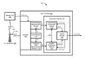
- FIG. 1shows elements of a navigation system according to some embodiments of the present disclosure.
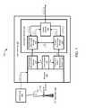
- FIG. 2shows a process for the navigation system of FIG. 1 according to some embodiments of the present disclosure.
- Embodiments of the present disclosureprovide elements of a system that enables navigation using television signals.
- wireless television signals received by a user deviceare used to provide information regarding the position and velocity of the user device, as well as information regarding time and frequency.
- This informationcan also be used for purposes other than navigation.
- the provided informationcan be used in the operation of femtocells, for example as described in U.S. patent application Ser. No. 12/476,992 filed Jun. 2, 2009, the disclosure thereof incorporated by reference herein in its entirety.
- pseudorange measurements of wireless television signalsare used to provide range and time information to a user device.
- Doppler measurements of the wireless television signalsare used to provide velocity and frequency information.
- satellitesIn contrast to satellites, television towers are stationary and horizontally distributed. Thus, Doppler shifts are almost entirely due to user horizontal movement. This fact makes Doppler positioning more suitable to television positioning than to GPS positioning.
- This navigation information(range, time, velocity, and frequency) is combined and used recursively with subsequent measurements to increase the accuracy of the navigation information.
- Doppler effectis a phenomenon of an effective frequency shift of a waveform due to relative movement of the origin and target of the waveform.
- the frequency f of a received waveformincreases as the relative distance between the transmitter receiver decreases, as shown in equation (1)
- f 0is the frequency of the waveform as transmitted
- cis the speed of waveform, in this case the speed of light
- ⁇is a fractional pilot frequency offset (FPFO) measurement by a receiver of the waveform.
- FPFOfractional pilot frequency offset
- FPFO ⁇ measured at the receiveris based on pilot frequency measurements made at the receiver and a monitor unit, f user and f mon , respectively.
- a monitor unitis a stationary receiver at a known location (thus eliminating the Doppler effect) and is expected to have an insignificant measurement error, ⁇ mon , compared to a user receiver measurement error, ⁇ user .
- FPFO ⁇is a fractional local oscillator offset (FLOO).
- FLOOfractional local oscillator offset
- f LOis a local oscillator frequency
- f LO,nomis the nominal value.
- FPFO ⁇consists of user velocity vector ⁇ , FLOO ⁇ , and a measurement error given by equation (8).
- ⁇is an n ⁇ 1 vector of FPFO measurements
- ⁇ ⁇is an n ⁇ 1 measurement error vector.
- the number of measurementsis given by n and G is an n ⁇ 4 geometry matrix such that
- G ⁇is the pseudo-inverse of the geometry matrix G. Since relative position is an accumulation of velocity, the user position û(t) can be estimated by integration of the estimate velocity ⁇ circumflex over ( ⁇ ) ⁇ ( ⁇ ) with respect to the initial user position u(0), as shown in equation (18).
- u ⁇ ⁇ ( t )u ⁇ ( 0 ) + ⁇ 0 t ⁇ ⁇ ⁇ ⁇ ( ⁇ ) ⁇ d ⁇ ( 18 )
- Doppler positioning and timing based on FPFO measurementsis combined with pseudorange-based positioning and timing based on pseudorange measurements.
- the measurements and variables usedare shown in Table 1.
- FPFO measurementsrelate to velocity and frequency offset
- range measurementsrelate to position and time offset, with respective outputs of velocity and position.
- the user variables x( u x ,u y ,u z ) (19)
- Pseudorange-based positioning and timingprovides an absolute position estimate while Doppler positioning generates a relative position estimate with respect to an initial location.
- a hybrid approachis used. Because these methods use two sets of measurements for position and time estimation, a hybrid solution taking both solutions together provides more reliable and accurate results. For example, these two sets of measurements can be combined by a common estimator.
- One example implementationuses a Kalman filter taking position estimates from pseudorange-based positioning and velocity estimates from Doppler positioning to generate more refined estimates.
- tight integrationis possible as has been done in the integration of GPS and inertial sensors (INS), which many GPS manufacturers adopt to improve the reliability of GPS. These position or velocity estimates can be fed back to individual positioning engines to improve their sensitivity by reducing search windows.
- the hybrid TV pseudorange and Doppler positioningdoes not need additional hardware because they use different measurements from the same hardware.
- FIG. 1shows elements of a navigation system 100 according to some embodiments of the present disclosure.
- the elements of navigation system 100are presented in one arrangement, other embodiments may feature other arrangements, as will be apparent to one skilled in the relevant arts based on the disclosure and teachings provided herein.
- elements of navigation system 100can be implemented in hardware, software, or combinations thereof.
- navigation system 100includes a user device 102 , a television (TV) transmitter 104 , and a monitor unit 106 .
- user deviceis meant to refer to any object capable of implementing the navigation techniques described herein. Examples of user devices include PDAs, mobile phones, cars and other vehicles, and any object which could include a chip or software implementing the navigation techniques described herein. Further, the term “user device” is not intended to be limited to devices which are operated by “users.”
- Both user device 102 and monitor unit 106receive wireless television signals 130 transmitted by television transmitter 104 .
- Monitor unit 106determines times of transmission TOT and frequencies f mon of television signals 130 , and reports these measurements to user device 102 .
- User device 102includes a receiver configured to receive television signals 130 and measurements TOT and f mon .
- User device 102also includes a clock module 110 configured to generate a clock signal ck, a pseudorange measurement module 112 configured to determine pseudoranges ⁇ based on clock signal ck, times of transmission TOT, and television signal 130 , a frequency offset measurement module 114 configured to determine frequency offsets ⁇ of television signal 130 based on clock signal ck and frequencies f user and f mon of television signals 130 , and an estimation module 116 configured to determine estimates ⁇ circumflex over (û) ⁇ , ⁇ circumflex over ( ⁇ circumflex over ( ⁇ ) ⁇ of the position and velocity of user device 102 , as well as estimates ⁇ circumflex over ( ⁇ circumflex over (b) ⁇ , ⁇ circumflex over ( ⁇ circumflex over ( ⁇ ) ⁇ of the time offset and frequency offset of clock signal ck, based on pseudoranges ⁇ , frequency offsets ⁇ , and geometry matrix G.
- Estimation module 116includes a pseudorange processing module 118 configured to determine interim estimates û, ⁇ circumflex over (b) ⁇ of the location of user device 102 , and the time offset of clock signal ck, based on pseudoranges ⁇ , geometry matrix G, and estimates ⁇ circumflex over (û) ⁇ , ⁇ circumflex over ( ⁇ circumflex over ( ⁇ ) ⁇ and ⁇ circumflex over ( ⁇ circumflex over (b) ⁇ , ⁇ circumflex over ( ⁇ circumflex over ( ⁇ ) ⁇ .
- pseudorange processing module 118configured to determine interim estimates û, ⁇ circumflex over (b) ⁇ of the location of user device 102 , and the time offset of clock signal ck, based on pseudoranges ⁇ , geometry matrix G, and estimates ⁇ circumflex over (û) ⁇ , ⁇ circumflex over ( ⁇ circumflex over ( ⁇ ) ⁇ and ⁇ circumflex over ( ⁇ circumflex over (b) ⁇ , ⁇ circumflex over ( ⁇ circumflex over ( ⁇ ) ⁇ .
- Estimation module 116also includes a Doppler processing module 120 configured to determine interim estimates ⁇ circumflex over ( ⁇ ) ⁇ , ⁇ circumflex over ( ⁇ ) ⁇ of the velocity of user device 102 , and the frequency offset of clock signal ck, based on frequency offsets ⁇ , geometry matrix G, and estimates ⁇ circumflex over (û) ⁇ , ⁇ circumflex over ( ⁇ circumflex over ( ⁇ ) ⁇ and ⁇ circumflex over ( ⁇ circumflex over (b) ⁇ , ⁇ circumflex over ( ⁇ circumflex over ( ⁇ ) ⁇ .
- Doppler processing module 120configured to determine interim estimates ⁇ circumflex over ( ⁇ ) ⁇ , ⁇ circumflex over ( ⁇ ) ⁇ of the velocity of user device 102 , and the frequency offset of clock signal ck, based on frequency offsets ⁇ , geometry matrix G, and estimates ⁇ circumflex over (û) ⁇ , ⁇ circumflex over ( ⁇ circumflex over ( ⁇ ) ⁇ and ⁇ circumflex over ( ⁇ circumflex over (b) ⁇ , ⁇ circumflex over (
- Estimation module 116further includes a hybrid module 122 configured to determine estimates ⁇ circumflex over (û) ⁇ , ⁇ circumflex over ( ⁇ circumflex over ( ⁇ ) ⁇ and ⁇ circumflex over ( ⁇ circumflex over (b) ⁇ , ⁇ circumflex over ( ⁇ circumflex over ( ⁇ ) ⁇ based on interim estimates û, ⁇ circumflex over (b) ⁇ and ⁇ circumflex over ( ⁇ ) ⁇ , ⁇ circumflex over ( ⁇ ) ⁇ .
- estimates generated by hybrid module 122are denoted by a double hat (for example, ⁇ circumflex over (û) ⁇ ), while interim estimates, which are generated by pseudorange processing module 118 and Doppler processing module 120 , are denoted by a single hat (for example, û).
- FIG. 2shows a process 200 for navigation system 100 of FIG. 1 according to some embodiments of the present disclosure.
- the elements of process 200are presented in one arrangement, other embodiments may feature other arrangements, as will be apparent to one skilled in the relevant arts based on the disclosure and teachings provided herein.
- some or all of the steps of process 200can be executed in a different order, concurrently, and the like.
- monitor unit 106determines times of transmission TOT and frequencies f mon of television signal 130 , and reports these measurements to user device 102 .
- monitor unitsare further described in U.S. Pat. No. 7,471,244 issued Dec. 30, 2008, the disclosure thereof incorporated by reference herein in its entirety.
- Receiver 108 of user device 102receives television signals 130 as well.
- pseudorange measurement module 112determines pseudoranges ⁇ based on clock signal ck, times of transmission TOT, and television signal 130 . Determination of pseudoranges based on television signals is further described in the patents cited above.
- frequency offset measurement module 114determines frequency offsets ⁇ of television signal 130 based on clock signal ck and frequencies f user and f mon of television signals 130 .
- frequency offsets ⁇are measured for one or more television pilot signals present in television signal 130 .
- ATSC and NTSC television signalsinclude strong pilots suitable for frequency offset measurements.
- Other television signalsinclude scattered pilot signals, repeating pilot signals, and the like.
- other components of television signal 130can be used instead of, or in addition to, television pilot signals.
- User device 102can employ multiple television signals 130 from the same or different television transmitters 104 .
- For each television signal 130if a pseudorange measurement is used, a frequency offset measurement should be used as well. However, if no pseudorange measurement is available for a television signal 130 , a frequency offset measurement of that television signal 130 may be used, in conjunction with measurements of pseudorange and frequency offsets from other television signals 130 .
- pseudorange processing module 118determines interim estimates û, ⁇ circumflex over (b) ⁇ of the location of user device 102 , and the time offset of clock signal ck, based on pseudoranges ⁇ , geometry matrix G, and estimates ⁇ circumflex over (û) ⁇ , ⁇ circumflex over ( ⁇ circumflex over ( ⁇ ) ⁇ and ⁇ circumflex over ( ⁇ circumflex over (b) ⁇ , ⁇ circumflex over ( ⁇ circumflex over ( ⁇ ) ⁇ from previous operations of hybrid module 122 .
- Doppler processing module 120determines interim estimates ⁇ circumflex over ( ⁇ ) ⁇ , ⁇ circumflex over ( ⁇ ) ⁇ of the velocity of user device 102 , and the frequency offset of clock signal ck, based on frequency offsets ⁇ , geometry matrix G, and estimates ⁇ circumflex over (û) ⁇ , ⁇ circumflex over ( ⁇ circumflex over ( ⁇ ) ⁇ and ⁇ circumflex over ( ⁇ circumflex over (b) ⁇ , ⁇ circumflex over ( ⁇ circumflex over ( ⁇ ) ⁇ from previous operations of hybrid module 122 .
- geometry matrix Gincludes knowledge of the interim estimate û of the location of user device 102 determined in step 208 .
- hybrid module 122determines estimates ⁇ circumflex over (û) ⁇ , ⁇ circumflex over ( ⁇ circumflex over ( ⁇ ) ⁇ and ⁇ circumflex over ( ⁇ circumflex over (b) ⁇ , ⁇ circumflex over ( ⁇ circumflex over ( ⁇ ) ⁇ based on interim estimates û, ⁇ circumflex over (b) ⁇ and ⁇ circumflex over ( ⁇ ) ⁇ , ⁇ circumflex over ( ⁇ ) ⁇ .
- Process 200can repeat as desired, with each set of interim estimates û, ⁇ circumflex over (b) ⁇ and ⁇ circumflex over ( ⁇ ) ⁇ , ⁇ circumflex over ( ⁇ ) ⁇ determined based on previous estimates ⁇ circumflex over (û) ⁇ , ⁇ circumflex over ( ⁇ circumflex over ( ⁇ ) ⁇ and ⁇ circumflex over ( ⁇ circumflex over (b) ⁇ , ⁇ circumflex over ( ⁇ circumflex over ( ⁇ ) ⁇ , thereby increasing the accuracy of the estimates.
- Monitor unit 106can repeat the determination of times of transmission TOT and frequencies f mon of television signals 130 , and report these measurements to user device 102 , as desired.
- Embodiments of the disclosurecan be implemented in digital electronic circuitry, or in computer hardware, firmware, software, or in combinations of them.
- Embodiments of the disclosurecan be implemented in a computer program product tangibly embodied in a machine-readable storage device for execution by a programmable processor; and method steps of the disclosure can be performed by a programmable processor executing a program of instructions to perform functions of the disclosure by operating on input data and generating output.
- the disclosurecan be implemented advantageously in one or more computer programs that are executable on a programmable system including at least one programmable processor coupled to receive data and instructions from, and to transmit data and instructions to, a data storage system, at least one input device, and at least one output device.
- Each computer programcan be implemented in a high-level procedural or object-oriented programming language, or in assembly or machine language if desired; and in any case, the language can be a compiled or interpreted language.
- Suitable processorsinclude, by way of example, both general and special purpose microprocessors.
- a processorwill receive instructions and data from a read-only memory and/or a random access memory.
- a computerwill include one or more mass storage devices for storing data files; such devices include magnetic disks, such as internal hard disks and removable disks; magneto-optical disks; and optical disks.
- Storage devices suitable for tangibly embodying computer program instructions and datainclude all forms of non-volatile memory, including by way of example semiconductor memory devices, such as EPROM, EEPROM, and flash memory devices; magnetic disks such as internal hard disks and removable disks; magneto-optical disks; and CD-ROM disks. Any of the foregoing can be supplemented by, or incorporated in, ASICs (application-specific integrated circuits).
- semiconductor memory devicessuch as EPROM, EEPROM, and flash memory devices
- magnetic diskssuch as internal hard disks and removable disks
- magneto-optical disksmagneto-optical disks
- CD-ROM disksCD-ROM disks
Landscapes
- Engineering & Computer Science (AREA)
- Radar, Positioning & Navigation (AREA)
- Remote Sensing (AREA)
- Computer Networks & Wireless Communication (AREA)
- Physics & Mathematics (AREA)
- General Physics & Mathematics (AREA)
- Position Fixing By Use Of Radio Waves (AREA)
Abstract
Description
{circumflex over (υ)}=c·φ (2)
fmon=f0+εmon≈f0 (3)
fuser=f0(1−v/c)+ηf0+εuser (4)
υ=(υx,υy,υz) (7)
ei=(û−si)/∥û−si∥ (10)
si=(sx,i,sy,i,sz,i) (11)
u=(ux,uy,uz) (12)
φ=Gy+εφ (13)
ŷ=G†φ (17)
| TABLE 1 | ||
| Positioning | Measurements | Variables |
| Doppler | Doppler frequency shift (φ) | velocity (υ) |
| frequency offset (η) | ||
| Pseudoranging | pseudorange (ρ ) | position (u) |
| time offset (b) | ||
x=(ux,uy,uz) (19)
ρ→û→{circumflex over (υ)} (20)
φ→{circumflex over (υ)}→û (21)
Claims (18)
Priority Applications (1)
| Application Number | Priority Date | Filing Date | Title |
|---|---|---|---|
| US12/582,051US8125389B1 (en) | 2008-10-20 | 2009-10-20 | Doppler-aided positioning, navigation, and timing using broadcast television signals |
Applications Claiming Priority (2)
| Application Number | Priority Date | Filing Date | Title |
|---|---|---|---|
| US10684908P | 2008-10-20 | 2008-10-20 | |
| US12/582,051US8125389B1 (en) | 2008-10-20 | 2009-10-20 | Doppler-aided positioning, navigation, and timing using broadcast television signals |
Publications (1)
| Publication Number | Publication Date |
|---|---|
| US8125389B1true US8125389B1 (en) | 2012-02-28 |
Family
ID=45694478
Family Applications (1)
| Application Number | Title | Priority Date | Filing Date |
|---|---|---|---|
| US12/582,051Expired - Fee RelatedUS8125389B1 (en) | 2008-10-20 | 2009-10-20 | Doppler-aided positioning, navigation, and timing using broadcast television signals |
Country Status (1)
| Country | Link |
|---|---|
| US (1) | US8125389B1 (en) |
Cited By (2)
| Publication number | Priority date | Publication date | Assignee | Title |
|---|---|---|---|---|
| US8351961B2 (en) | 2006-10-17 | 2013-01-08 | Exelis Inc. | System and related circuits and methods for detecting and locating cellular telephone use within a geographical area or facility |
| US20160127931A1 (en)* | 2014-10-30 | 2016-05-05 | Bastille Networks, Inc. | Efficient Localization of Transmitters Within Complex Electromagnetic Environments |
Citations (87)
| Publication number | Priority date | Publication date | Assignee | Title |
|---|---|---|---|---|
| JPS58129277A (en) | 1982-01-28 | 1983-08-02 | Japan Radio Co Ltd | Radio navigation device of hyperbola system |
| DE3242997A1 (en) | 1982-11-20 | 1984-05-24 | Standard Elektrik Lorenz Ag, 7000 Stuttgart | Position indicating system |
| US4555707A (en) | 1982-08-27 | 1985-11-26 | Connelly Will A | Television pulsed navigation system |
| US4652884A (en) | 1984-07-20 | 1987-03-24 | Deutsche Forschungs-Und Versuchsanstalt Fur Luft-Und Raumfahrt E.V. | Satellite navigational system and method |
| US4700306A (en) | 1981-06-24 | 1987-10-13 | Kungalvsgruppen Areng, Hjerpe, Wallmander Ab | System for the visualization of the movements of marine vessels by television display |
| US4894662A (en) | 1982-03-01 | 1990-01-16 | Western Atlas International, Inc. | Method and system for determining position on a moving platform, such as a ship, using signals from GPS satellites |
| GB2222922A (en) | 1988-06-16 | 1990-03-21 | Spectronics Micro Syst Ltd | Vehicle location system |
| US5045861A (en) | 1987-08-10 | 1991-09-03 | The Lynxvale - Cril Partnership | Navigation and tracking system |
| GB2254508A (en) | 1991-04-02 | 1992-10-07 | James Collier Mitchinson | Vehicle location determining system |
| US5157686A (en) | 1990-05-24 | 1992-10-20 | Cylink Corporation | Method and apparatus for the modulation of spread spectrum radio signals |
| US5166952A (en) | 1990-05-24 | 1992-11-24 | Cylink Corporation | Method and apparatus for the reception and demodulation of spread spectrum radio signals |
| US5271034A (en) | 1991-08-26 | 1993-12-14 | Avion Systems, Inc. | System and method for receiving and decoding global positioning satellite signals |
| US5323322A (en) | 1992-03-05 | 1994-06-21 | Trimble Navigation Limited | Networked differential GPS system |
| US5398034A (en) | 1993-03-29 | 1995-03-14 | Stanford Telecommunications, Inc. | Vector delay lock loop processing of radiolocation transmitter signals |
| US5481316A (en) | 1990-11-05 | 1996-01-02 | Samsung Electronics Co., Ltd. | System, apparatus and method for canceling televison ghost signals |
| US5504492A (en) | 1994-08-01 | 1996-04-02 | Honeywell Inc. | Look ahead satellite positioning system position error bound monitoring system |
| US5510801A (en)* | 1994-03-01 | 1996-04-23 | Stanford Telecommunications, Inc. | Location determination system and method using television broadcast signals |
| US5604765A (en) | 1994-12-23 | 1997-02-18 | Stanford Telecommunications, Inc. | Position enhanced communication system including system for embedding CDMA navigation beacons under the communications signals of a wireless communication system |
| US5630206A (en) | 1994-08-11 | 1997-05-13 | Stanford Telecommunications, Inc. | Position enhanced cellular telephone system |
| US5648982A (en) | 1994-09-09 | 1997-07-15 | Omnipoint Corporation | Spread spectrum transmitter |
| US5774829A (en) | 1995-12-12 | 1998-06-30 | Pinterra Corporation | Navigation and positioning system and method using uncoordinated beacon signals in conjunction with an absolute positioning system |
| US5784339A (en) | 1997-04-16 | 1998-07-21 | Ocean Vision Technology, Inc. | Underwater location and communication system |
| US5835060A (en) | 1996-10-07 | 1998-11-10 | Lockheed Martin Corporation | Self-resolving LBI triangulation |
| US5920284A (en) | 1996-09-30 | 1999-07-06 | Qualcomm Incorporated | Ambiguity resolution for ambiguous position solutions using satellite beams |
| US5953311A (en) | 1997-02-18 | 1999-09-14 | Discovision Associates | Timing synchronization in a receiver employing orthogonal frequency division multiplexing |
| US5952958A (en) | 1996-04-05 | 1999-09-14 | Discovision Associates | Positioning system and method |
| US6006097A (en) | 1997-11-24 | 1999-12-21 | Telefonaktiebolaget L M Ericsson (Publ) | Method for determining position of mobile communication terminals |
| US6016119A (en) | 1995-10-09 | 2000-01-18 | Snaptrack, Inc. | Method and apparatus for determining the location of an object which may have an obstructed view of the sky |
| US6078284A (en) | 1996-09-30 | 2000-06-20 | Qualcomm Incorporated | Passive position determination using two low-earth orbit satellites |
| US6094168A (en) | 1995-09-19 | 2000-07-25 | Cambridge Positioning Systems Ltd. | Position determining system |
| US6107959A (en) | 1996-09-30 | 2000-08-22 | Qualcomm Incorporated | Positioning determination using one low-Earth orbit satellite |
| US6137441A (en) | 1998-09-09 | 2000-10-24 | Qualcomm Incorporated | Accurate range and range rate determination in a satellite communications system |
| US6144413A (en) | 1998-06-25 | 2000-11-07 | Analog Devices, Inc. | Synchronization signal detection and phase estimation apparatus and method |
| US6147642A (en) | 1998-06-05 | 2000-11-14 | Decisionmark Corp. | Method and apparatus for limiting access to satellite communication signals |
| US6181921B1 (en) | 1994-08-19 | 2001-01-30 | Seiko Epson Corporation | Broadcasting station data detector and broadcast receiver for moving body that search a channel map based on location |
| US6184921B1 (en) | 1998-02-20 | 2001-02-06 | Samsung Electronics Co., Ltd. | Method for transmitting VSB digital TV with carrier frequency near co-channel NTSC audio carrier frequency |
| US6201497B1 (en) | 1997-09-30 | 2001-03-13 | Dlb Limited | Enhanced global navigation satellite system |
| US6215778B1 (en) | 1995-06-30 | 2001-04-10 | Interdigital Technology Corporation | Bearer channel modification system for a code division multiple access (CDMA) communication system |
| US6289280B1 (en) | 1999-12-10 | 2001-09-11 | Qualcomm Incorporated | Method and apparatus for determining an algebraic solution to GPS terrestrial hybrid location system equations |
| US6317500B1 (en) | 1995-04-28 | 2001-11-13 | Trimble Navigation Limited | Method and apparatus for location-sensitive decryption of an encrypted signal |
| US6317452B1 (en) | 1994-09-09 | 2001-11-13 | Xircom, Inc. | Method and apparatus for wireless spread spectrum communication with preamble sounding gap |
| US6373432B1 (en) | 1997-03-21 | 2002-04-16 | The Board Of Trustees Of The Leland Stanford Junior University | System using leo satellites for centimeter-level navigation |
| US6374177B1 (en) | 2000-09-20 | 2002-04-16 | Motorola, Inc. | Method and apparatus for providing navigational services in a wireless communication device |
| US6400753B1 (en) | 1996-04-25 | 2002-06-04 | Sirf Technology, Inc. | Pseudo-noise correlator for a GPS spread spectrum receiver |
| US6433740B1 (en) | 1994-03-25 | 2002-08-13 | Qualcomm Incorporated | Determination method for use with analog cellular system |
| US6437832B1 (en) | 1999-10-21 | 2002-08-20 | General Electric Company | Mitigation of multipath using ultra wideband DTV overlay signal |
| US20020122003A1 (en) | 2001-01-05 | 2002-09-05 | Patwari Neal K. | Method and apparatus for location estimation |
| US20020168988A1 (en) | 2001-03-15 | 2002-11-14 | Saed Younis | Time acquisition in a wireless position determination system |
| US6484034B1 (en) | 2001-07-24 | 2002-11-19 | Hitachi, Ltd. | Radio handset and position location system |
| US20020184653A1 (en) | 2001-02-02 | 2002-12-05 | Pierce Matthew D. | Services based on position location using broadcast digital television signals |
| US6522297B1 (en) | 2001-02-02 | 2003-02-18 | Rosum Corporation | Position location using ghost canceling reference television signals |
| US6559800B2 (en) | 2001-02-02 | 2003-05-06 | Rosum Corporation | Position location using broadcast analog television signals |
| US6559894B2 (en) | 1999-10-21 | 2003-05-06 | Digeo, Inc. | Block-adaptive equalization using partial decision feedback in digital broadcast communications |
| US6590529B2 (en) | 2000-02-14 | 2003-07-08 | Mysky Communications | Individualized, location specific weather forecasting system |
| US20030162547A1 (en) | 2001-08-07 | 2003-08-28 | Mcnair Bruce E. | Simulcasting OFDM system having mobile station location identification |
| US6646603B2 (en) | 2000-06-16 | 2003-11-11 | Koninklijke Philips Electronics, N.V. | Method of providing an estimate of a location |
| US6717547B2 (en) | 2001-06-21 | 2004-04-06 | Rosum Corporation | Position location using broadcast television signals and mobile telephone signals |
| US20040073914A1 (en) | 2002-07-05 | 2004-04-15 | Spilker James J. | Precision time transfer using television signals |
| US6727847B2 (en) | 2001-04-03 | 2004-04-27 | Rosum Corporation | Using digital television broadcast signals to provide GPS aiding information |
| US6753812B2 (en) | 2001-02-02 | 2004-06-22 | Rosum Corporation | Time-gated delay lock loop tracking of digital television signals |
| US20040201779A1 (en) | 2001-02-02 | 2004-10-14 | Spilker James J. | Symbol clock recovery for the ATSC digital television signal |
| US6806830B2 (en) | 2001-12-31 | 2004-10-19 | Texas Instruments Incorporated | Electronic device precision location via local broadcast signals |
| US6839024B2 (en) | 2001-06-21 | 2005-01-04 | Rosum Corporation | Position determination using portable pseudo-television broadcast transmitters |
| US6859173B2 (en) | 2001-06-21 | 2005-02-22 | The Rosum Corporation | Position location using broadcast television signals and mobile telephone signals |
| US6861984B2 (en) | 2001-02-02 | 2005-03-01 | Rosum Corporation | Position location using broadcast digital television signals |
| US20050066373A1 (en) | 2001-02-02 | 2005-03-24 | Matthew Rabinowitz | Position location using broadcast digital television signals |
| US6914560B2 (en) | 2001-08-17 | 2005-07-05 | The Rosum Corporation | Position location using broadcast digital television signals comprising pseudonoise sequences |
| US6917328B2 (en) | 2001-11-13 | 2005-07-12 | Rosum Corporation | Radio frequency device for receiving TV signals and GPS satellite signals and performing positioning |
| US6937866B2 (en) | 2001-02-23 | 2005-08-30 | Cambridge Positioning Systems Limited | Positioning systems and methods |
| US6952182B2 (en)* | 2001-08-17 | 2005-10-04 | The Rosom Corporation | Position location using integrated services digital broadcasting—terrestrial (ISDB-T) broadcast television signals |
| US6963306B2 (en) | 2001-02-02 | 2005-11-08 | Rosum Corp. | Position location and data transmission using pseudo digital television transmitters |
| US20050251844A1 (en) | 2001-02-02 | 2005-11-10 | Massimiliano Martone | Blind correlation for high precision ranging of coded OFDM signals |
| US6970132B2 (en) | 2001-02-02 | 2005-11-29 | Rosum Corporation | Targeted data transmission and location services using digital television signaling |
| US7042949B1 (en) | 2001-04-03 | 2006-05-09 | Rosum Corporation | Robust data transmission using broadcast digital television signals |
| US7042396B2 (en) | 2001-08-17 | 2006-05-09 | Rosom Corporation | Position location using digital audio broadcast signals |
| US20060116820A1 (en)* | 2003-08-14 | 2006-06-01 | Fujitsu Limited | Information processing device and gps positioning method |
| US7126536B2 (en) | 2001-02-02 | 2006-10-24 | Rosum Corporation | Position location using terrestrial digital video broadcast television signals |
| US20070050824A1 (en) | 2001-02-02 | 2007-03-01 | Andy Lee | Location identification using broadcast wireless signal signatures |
| US20070121555A1 (en) | 2005-11-08 | 2007-05-31 | David Burgess | Positioning using is-95 cdma signals |
| US20070131079A1 (en) | 2005-11-02 | 2007-06-14 | Guttorm Opshaug | Wide-lane pseudorange measurements using fm signals |
| US7260378B2 (en) | 1999-07-29 | 2007-08-21 | Bryan Holland | Locator system for processing commercial 911 requests |
| US7269424B2 (en) | 2002-10-16 | 2007-09-11 | Sony Ericsson Mobile Communications Ab | Mobile terminal implementing a ranging signal receiver and method |
| US7463195B2 (en) | 2001-06-21 | 2008-12-09 | Rosum Corporation | Position location using global positioning signals augmented by broadcast television signals |
| US7466266B2 (en) | 2006-06-22 | 2008-12-16 | Rosum Corporation | Psuedo television transmitters for position location |
| US7471244B2 (en) | 2001-02-02 | 2008-12-30 | Rosum Corporation | Monitor units for television signals |
| US20090070847A1 (en) | 2007-07-06 | 2009-03-12 | Rosum Corporation | Positioning with Time Sliced Single Frequency Networks |
| US20090175379A1 (en) | 2007-12-12 | 2009-07-09 | Rosum Corporation | Transmitter Identification For Wireless Signals Having A Digital Audio Broadcast Physical Layer |
- 2009
- 2009-10-20USUS12/582,051patent/US8125389B1/ennot_activeExpired - Fee Related
Patent Citations (90)
| Publication number | Priority date | Publication date | Assignee | Title |
|---|---|---|---|---|
| US4700306A (en) | 1981-06-24 | 1987-10-13 | Kungalvsgruppen Areng, Hjerpe, Wallmander Ab | System for the visualization of the movements of marine vessels by television display |
| JPS58129277A (en) | 1982-01-28 | 1983-08-02 | Japan Radio Co Ltd | Radio navigation device of hyperbola system |
| US4894662A (en) | 1982-03-01 | 1990-01-16 | Western Atlas International, Inc. | Method and system for determining position on a moving platform, such as a ship, using signals from GPS satellites |
| US4555707A (en) | 1982-08-27 | 1985-11-26 | Connelly Will A | Television pulsed navigation system |
| DE3242997A1 (en) | 1982-11-20 | 1984-05-24 | Standard Elektrik Lorenz Ag, 7000 Stuttgart | Position indicating system |
| US4652884A (en) | 1984-07-20 | 1987-03-24 | Deutsche Forschungs-Und Versuchsanstalt Fur Luft-Und Raumfahrt E.V. | Satellite navigational system and method |
| US5045861A (en) | 1987-08-10 | 1991-09-03 | The Lynxvale - Cril Partnership | Navigation and tracking system |
| GB2222922A (en) | 1988-06-16 | 1990-03-21 | Spectronics Micro Syst Ltd | Vehicle location system |
| US5157686A (en) | 1990-05-24 | 1992-10-20 | Cylink Corporation | Method and apparatus for the modulation of spread spectrum radio signals |
| US5166952A (en) | 1990-05-24 | 1992-11-24 | Cylink Corporation | Method and apparatus for the reception and demodulation of spread spectrum radio signals |
| US5481316A (en) | 1990-11-05 | 1996-01-02 | Samsung Electronics Co., Ltd. | System, apparatus and method for canceling televison ghost signals |
| GB2254508A (en) | 1991-04-02 | 1992-10-07 | James Collier Mitchinson | Vehicle location determining system |
| US5271034A (en) | 1991-08-26 | 1993-12-14 | Avion Systems, Inc. | System and method for receiving and decoding global positioning satellite signals |
| US5323322A (en) | 1992-03-05 | 1994-06-21 | Trimble Navigation Limited | Networked differential GPS system |
| US5398034A (en) | 1993-03-29 | 1995-03-14 | Stanford Telecommunications, Inc. | Vector delay lock loop processing of radiolocation transmitter signals |
| US5510801A (en)* | 1994-03-01 | 1996-04-23 | Stanford Telecommunications, Inc. | Location determination system and method using television broadcast signals |
| US6433740B1 (en) | 1994-03-25 | 2002-08-13 | Qualcomm Incorporated | Determination method for use with analog cellular system |
| US5504492A (en) | 1994-08-01 | 1996-04-02 | Honeywell Inc. | Look ahead satellite positioning system position error bound monitoring system |
| US5630206A (en) | 1994-08-11 | 1997-05-13 | Stanford Telecommunications, Inc. | Position enhanced cellular telephone system |
| US6181921B1 (en) | 1994-08-19 | 2001-01-30 | Seiko Epson Corporation | Broadcasting station data detector and broadcast receiver for moving body that search a channel map based on location |
| US5648982A (en) | 1994-09-09 | 1997-07-15 | Omnipoint Corporation | Spread spectrum transmitter |
| US6317452B1 (en) | 1994-09-09 | 2001-11-13 | Xircom, Inc. | Method and apparatus for wireless spread spectrum communication with preamble sounding gap |
| US5604765A (en) | 1994-12-23 | 1997-02-18 | Stanford Telecommunications, Inc. | Position enhanced communication system including system for embedding CDMA navigation beacons under the communications signals of a wireless communication system |
| US6317500B1 (en) | 1995-04-28 | 2001-11-13 | Trimble Navigation Limited | Method and apparatus for location-sensitive decryption of an encrypted signal |
| US6215778B1 (en) | 1995-06-30 | 2001-04-10 | Interdigital Technology Corporation | Bearer channel modification system for a code division multiple access (CDMA) communication system |
| US6094168A (en) | 1995-09-19 | 2000-07-25 | Cambridge Positioning Systems Ltd. | Position determining system |
| US6016119A (en) | 1995-10-09 | 2000-01-18 | Snaptrack, Inc. | Method and apparatus for determining the location of an object which may have an obstructed view of the sky |
| US5774829A (en) | 1995-12-12 | 1998-06-30 | Pinterra Corporation | Navigation and positioning system and method using uncoordinated beacon signals in conjunction with an absolute positioning system |
| US5952958A (en) | 1996-04-05 | 1999-09-14 | Discovision Associates | Positioning system and method |
| US6400753B1 (en) | 1996-04-25 | 2002-06-04 | Sirf Technology, Inc. | Pseudo-noise correlator for a GPS spread spectrum receiver |
| US6107959A (en) | 1996-09-30 | 2000-08-22 | Qualcomm Incorporated | Positioning determination using one low-Earth orbit satellite |
| US6078284A (en) | 1996-09-30 | 2000-06-20 | Qualcomm Incorporated | Passive position determination using two low-earth orbit satellites |
| US5920284A (en) | 1996-09-30 | 1999-07-06 | Qualcomm Incorporated | Ambiguity resolution for ambiguous position solutions using satellite beams |
| US5835060A (en) | 1996-10-07 | 1998-11-10 | Lockheed Martin Corporation | Self-resolving LBI triangulation |
| US5953311A (en) | 1997-02-18 | 1999-09-14 | Discovision Associates | Timing synchronization in a receiver employing orthogonal frequency division multiplexing |
| US6373432B1 (en) | 1997-03-21 | 2002-04-16 | The Board Of Trustees Of The Leland Stanford Junior University | System using leo satellites for centimeter-level navigation |
| US5784339A (en) | 1997-04-16 | 1998-07-21 | Ocean Vision Technology, Inc. | Underwater location and communication system |
| US6201497B1 (en) | 1997-09-30 | 2001-03-13 | Dlb Limited | Enhanced global navigation satellite system |
| US6006097A (en) | 1997-11-24 | 1999-12-21 | Telefonaktiebolaget L M Ericsson (Publ) | Method for determining position of mobile communication terminals |
| US6184921B1 (en) | 1998-02-20 | 2001-02-06 | Samsung Electronics Co., Ltd. | Method for transmitting VSB digital TV with carrier frequency near co-channel NTSC audio carrier frequency |
| US6147642A (en) | 1998-06-05 | 2000-11-14 | Decisionmark Corp. | Method and apparatus for limiting access to satellite communication signals |
| US6144413A (en) | 1998-06-25 | 2000-11-07 | Analog Devices, Inc. | Synchronization signal detection and phase estimation apparatus and method |
| US6137441A (en) | 1998-09-09 | 2000-10-24 | Qualcomm Incorporated | Accurate range and range rate determination in a satellite communications system |
| US7260378B2 (en) | 1999-07-29 | 2007-08-21 | Bryan Holland | Locator system for processing commercial 911 requests |
| US6559894B2 (en) | 1999-10-21 | 2003-05-06 | Digeo, Inc. | Block-adaptive equalization using partial decision feedback in digital broadcast communications |
| US6437832B1 (en) | 1999-10-21 | 2002-08-20 | General Electric Company | Mitigation of multipath using ultra wideband DTV overlay signal |
| US6289280B1 (en) | 1999-12-10 | 2001-09-11 | Qualcomm Incorporated | Method and apparatus for determining an algebraic solution to GPS terrestrial hybrid location system equations |
| US6590529B2 (en) | 2000-02-14 | 2003-07-08 | Mysky Communications | Individualized, location specific weather forecasting system |
| US6646603B2 (en) | 2000-06-16 | 2003-11-11 | Koninklijke Philips Electronics, N.V. | Method of providing an estimate of a location |
| US6374177B1 (en) | 2000-09-20 | 2002-04-16 | Motorola, Inc. | Method and apparatus for providing navigational services in a wireless communication device |
| US20020122003A1 (en) | 2001-01-05 | 2002-09-05 | Patwari Neal K. | Method and apparatus for location estimation |
| US6559800B2 (en) | 2001-02-02 | 2003-05-06 | Rosum Corporation | Position location using broadcast analog television signals |
| US20040201779A1 (en) | 2001-02-02 | 2004-10-14 | Spilker James J. | Symbol clock recovery for the ATSC digital television signal |
| US6522297B1 (en) | 2001-02-02 | 2003-02-18 | Rosum Corporation | Position location using ghost canceling reference television signals |
| US7372405B2 (en) | 2001-02-02 | 2008-05-13 | Rosum Corporation | Position location using digital video broadcast television signals |
| US20020184653A1 (en) | 2001-02-02 | 2002-12-05 | Pierce Matthew D. | Services based on position location using broadcast digital television signals |
| US7471244B2 (en) | 2001-02-02 | 2008-12-30 | Rosum Corporation | Monitor units for television signals |
| US20070050824A1 (en) | 2001-02-02 | 2007-03-01 | Andy Lee | Location identification using broadcast wireless signal signatures |
| US6963306B2 (en) | 2001-02-02 | 2005-11-08 | Rosum Corp. | Position location and data transmission using pseudo digital television transmitters |
| US6753812B2 (en) | 2001-02-02 | 2004-06-22 | Rosum Corporation | Time-gated delay lock loop tracking of digital television signals |
| US6961020B2 (en) | 2001-02-02 | 2005-11-01 | The Rosum Corporation | Position location using broadcast analog television signals |
| US7126536B2 (en) | 2001-02-02 | 2006-10-24 | Rosum Corporation | Position location using terrestrial digital video broadcast television signals |
| US20050251844A1 (en) | 2001-02-02 | 2005-11-10 | Massimiliano Martone | Blind correlation for high precision ranging of coded OFDM signals |
| US6970132B2 (en) | 2001-02-02 | 2005-11-29 | Rosum Corporation | Targeted data transmission and location services using digital television signaling |
| US6861984B2 (en) | 2001-02-02 | 2005-03-01 | Rosum Corporation | Position location using broadcast digital television signals |
| US20050066373A1 (en) | 2001-02-02 | 2005-03-24 | Matthew Rabinowitz | Position location using broadcast digital television signals |
| US6879286B2 (en) | 2001-02-02 | 2005-04-12 | The Rosum Corporation | Position location using ghost canceling reference television signals |
| US6937866B2 (en) | 2001-02-23 | 2005-08-30 | Cambridge Positioning Systems Limited | Positioning systems and methods |
| US20020168988A1 (en) | 2001-03-15 | 2002-11-14 | Saed Younis | Time acquisition in a wireless position determination system |
| US7042949B1 (en) | 2001-04-03 | 2006-05-09 | Rosum Corporation | Robust data transmission using broadcast digital television signals |
| US6727847B2 (en) | 2001-04-03 | 2004-04-27 | Rosum Corporation | Using digital television broadcast signals to provide GPS aiding information |
| US6859173B2 (en) | 2001-06-21 | 2005-02-22 | The Rosum Corporation | Position location using broadcast television signals and mobile telephone signals |
| US6717547B2 (en) | 2001-06-21 | 2004-04-06 | Rosum Corporation | Position location using broadcast television signals and mobile telephone signals |
| US7463195B2 (en) | 2001-06-21 | 2008-12-09 | Rosum Corporation | Position location using global positioning signals augmented by broadcast television signals |
| US6839024B2 (en) | 2001-06-21 | 2005-01-04 | Rosum Corporation | Position determination using portable pseudo-television broadcast transmitters |
| US6484034B1 (en) | 2001-07-24 | 2002-11-19 | Hitachi, Ltd. | Radio handset and position location system |
| US20030162547A1 (en) | 2001-08-07 | 2003-08-28 | Mcnair Bruce E. | Simulcasting OFDM system having mobile station location identification |
| US7042396B2 (en) | 2001-08-17 | 2006-05-09 | Rosom Corporation | Position location using digital audio broadcast signals |
| US6952182B2 (en)* | 2001-08-17 | 2005-10-04 | The Rosom Corporation | Position location using integrated services digital broadcasting—terrestrial (ISDB-T) broadcast television signals |
| US6914560B2 (en) | 2001-08-17 | 2005-07-05 | The Rosum Corporation | Position location using broadcast digital television signals comprising pseudonoise sequences |
| US6917328B2 (en) | 2001-11-13 | 2005-07-12 | Rosum Corporation | Radio frequency device for receiving TV signals and GPS satellite signals and performing positioning |
| US6806830B2 (en) | 2001-12-31 | 2004-10-19 | Texas Instruments Incorporated | Electronic device precision location via local broadcast signals |
| US20040073914A1 (en) | 2002-07-05 | 2004-04-15 | Spilker James J. | Precision time transfer using television signals |
| US7269424B2 (en) | 2002-10-16 | 2007-09-11 | Sony Ericsson Mobile Communications Ab | Mobile terminal implementing a ranging signal receiver and method |
| US20060116820A1 (en)* | 2003-08-14 | 2006-06-01 | Fujitsu Limited | Information processing device and gps positioning method |
| US20070131079A1 (en) | 2005-11-02 | 2007-06-14 | Guttorm Opshaug | Wide-lane pseudorange measurements using fm signals |
| US20070121555A1 (en) | 2005-11-08 | 2007-05-31 | David Burgess | Positioning using is-95 cdma signals |
| US7466266B2 (en) | 2006-06-22 | 2008-12-16 | Rosum Corporation | Psuedo television transmitters for position location |
| US20090070847A1 (en) | 2007-07-06 | 2009-03-12 | Rosum Corporation | Positioning with Time Sliced Single Frequency Networks |
| US20090175379A1 (en) | 2007-12-12 | 2009-07-09 | Rosum Corporation | Transmitter Identification For Wireless Signals Having A Digital Audio Broadcast Physical Layer |
Non-Patent Citations (19)
| Title |
|---|
| He et al, "Positioning Models and Systems Based on Digital Television Broadcasting Signals," Front. Electr. Electron. Eng. China, 2007, pp. 410-414.* |
| Li, X., et al., "Indoor Geolocation Using OFDM Signals in HIPERLAN/2 Wireless LANS," 11th IEEE International Symposium on Personal Indoor and Mobile Radio Communications, PIMRC 2000, Proceedings (Cat. No. 00TH8525), Proceedings of 11th International Symposium on Personal Indoor and Mobile Radio Communication, London, UK, Sep. 18-21, pp. 1449-1453, vol. 2, XPO10520871, 2000, Piscataway, NJ, USA, IEEE, USA, ISBN; 9-7803-6463-5, Chapter I and III. |
| Parkinson, B.W., et al., "Autonomous GPS Integrity Monitoring Using the Pseudorange Residual," Journal of the Institute of Navigation (1988), vol. 35, No. 2, pp. 255-274. |
| Rabinowitz, M., "A Differential Carrier Phase Navigation System Combining GPS with Low Earth Orbit Satellites for Rapid Resolution of Integer Cycle Ambiguities," PhD Thesis for Department of Electrical Engineering, Stanford University (Dec. 2000), pp. 59-73. |
| Rabinowitz, M., et al., "Positioning Using the ATSC Digital Television Signal," Rosum whitepaper, Online! 2001, XP002235053, Retrieved from the Internet on Mar. 13, 2003 at URL www.rosum.com/whitepaper 8-7-01.pdf. |
| Spilker, Jr., J.J., "Fundamentals of Signal Tracking Theory," Global Positioning System: Theory and Applications (1994), vol. 1, Chapter 7, pp. 245-327. |
| U.S. Appl. No. 10/008,613, Pierce, et al. |
| U.S. Appl. No. 11/380,691, Metzler, et al. |
| U.S. Appl. No. 11/535,485, Furman, et al. |
| U.S. Appl. No. 11/622,838, Rabinowitz, et al. |
| U.S. Appl. No. 11/770,162, Furman, et al. |
| U.S. Appl. No. 11/865,881, Opshaug, et al. |
| U.S. Appl. No. 12/117,676, Rabinowitz et al. |
| U.S. Appl. No. 12/209,971, Do, et al. |
| U.S. Appl. No. 12/263,731, Rabinowitz et al. |
| U.S. Appl. No. 12/351,841, Lee, et al. |
| U.S. Appl. No. 12/476,992, Do, et al. |
| U.S. Appl. No. 12/578,456, Opshaug, et al. |
| Van Dierendock, A.J., "GPS Receivers," Global Positioning System: Theory and Applications (1995), vol. 1, Chapter 8, pp. 329-407. |
Cited By (3)
| Publication number | Priority date | Publication date | Assignee | Title |
|---|---|---|---|---|
| US8351961B2 (en) | 2006-10-17 | 2013-01-08 | Exelis Inc. | System and related circuits and methods for detecting and locating cellular telephone use within a geographical area or facility |
| US20160127931A1 (en)* | 2014-10-30 | 2016-05-05 | Bastille Networks, Inc. | Efficient Localization of Transmitters Within Complex Electromagnetic Environments |
| US9551781B2 (en)* | 2014-10-30 | 2017-01-24 | Bastille Networks, Inc. | Efficient localization of transmitters within complex electromagnetic environments |
Similar Documents
| Publication | Publication Date | Title |
|---|---|---|
| US8193976B2 (en) | Positioning system, positioning IC chip, positioning method and positioning program for estimating a position of a receiver | |
| US10768264B2 (en) | Determination of a ground receiver position | |
| US8255160B2 (en) | Integrated mobile terminal navigation | |
| US7466266B2 (en) | Psuedo television transmitters for position location | |
| US20140002302A1 (en) | Ground Location Inertial Navigation Geopositioning System (Groundlings) | |
| US9766339B2 (en) | Global positioning system (GPS) and doppler augmentation (GDAUG) and space location inertial navigation geopositioning system (SPACELINGS) | |
| US9182497B2 (en) | Global positioning system (GPS) carrier phase cycle slip detection and correction | |
| US7808432B2 (en) | Systems and methods for a high-precision time of arrival ultra-wideband positioning system | |
| KR101179135B1 (en) | Apparatus and method for generating gps time | |
| US9365303B2 (en) | Position and elevation acquisition for orbit determination | |
| US8159393B2 (en) | Systems and methods for synthesizing GPS measurements to improve GPS location availability | |
| US20200041658A1 (en) | Gnss receiver with a capability to resolve ambiguities using an uncombined formulation | |
| US20090231192A1 (en) | Method and system for generating temporary ephemeris | |
| KR100938731B1 (en) | Self Positioning System of Bidirectional Pseudo Satellites | |
| US8125389B1 (en) | Doppler-aided positioning, navigation, and timing using broadcast television signals | |
| US8149168B1 (en) | Position determination using wireless local area network signals and television signals | |
| US8134498B2 (en) | Navigation-satellite tracking method and receiving station | |
| JP2005062046A (en) | Position assumption system of artificial satellite |
Legal Events
| Date | Code | Title | Description |
|---|---|---|---|
| AS | Assignment | Owner name:ROSUM CORPORATION, CALIFORNIA Free format text:ASSIGNMENT OF ASSIGNORS INTEREST;ASSIGNORS:OPSHAUG, GUTTORM;RUBIN, DIMITRI;DO, JUYONG;SIGNING DATES FROM 20091130 TO 20091217;REEL/FRAME:023706/0430 | |
| AS | Assignment | Owner name:ROSUM CORPORATION, CALIFORNIA Free format text:ASSIGNMENT OF ASSIGNORS INTEREST;ASSIGNORS:OPSHAUG, GUTTORM;DO, JUYONG;RUBIN, DIMITRI;SIGNING DATES FROM 20100324 TO 20100325;REEL/FRAME:024734/0956 | |
| AS | Assignment | Owner name:TRUEPOSITION, INC., PENNSYLVANIA Free format text:ASSIGNMENT OF ASSIGNORS INTEREST;ASSIGNOR:ROSUM CORPORATION;REEL/FRAME:025790/0936 Effective date:20101228 | |
| ZAAA | Notice of allowance and fees due | Free format text:ORIGINAL CODE: NOA | |
| ZAAB | Notice of allowance mailed | Free format text:ORIGINAL CODE: MN/=. | |
| STCF | Information on status: patent grant | Free format text:PATENTED CASE | |
| CC | Certificate of correction | ||
| FPAY | Fee payment | Year of fee payment:4 | |
| MAFP | Maintenance fee payment | Free format text:PAYMENT OF MAINTENANCE FEE, 8TH YR, SMALL ENTITY (ORIGINAL EVENT CODE: M2552); ENTITY STATUS OF PATENT OWNER: SMALL ENTITY Year of fee payment:8 | |
| AS | Assignment | Owner name:SKYHOOK HOLDING, INC., PENNSYLVANIA Free format text:CHANGE OF NAME;ASSIGNOR:TRUEPOSITION, INC.;REEL/FRAME:058812/0340 Effective date:20161221 | |
| FEPP | Fee payment procedure | Free format text:ENTITY STATUS SET TO UNDISCOUNTED (ORIGINAL EVENT CODE: BIG.); ENTITY STATUS OF PATENT OWNER: LARGE ENTITY | |
| FEPP | Fee payment procedure | Free format text:MAINTENANCE FEE REMINDER MAILED (ORIGINAL EVENT CODE: REM.); ENTITY STATUS OF PATENT OWNER: LARGE ENTITY | |
| LAPS | Lapse for failure to pay maintenance fees | Free format text:PATENT EXPIRED FOR FAILURE TO PAY MAINTENANCE FEES (ORIGINAL EVENT CODE: EXP.); ENTITY STATUS OF PATENT OWNER: LARGE ENTITY | |
| STCH | Information on status: patent discontinuation | Free format text:PATENT EXPIRED DUE TO NONPAYMENT OF MAINTENANCE FEES UNDER 37 CFR 1.362 | |
| FP | Lapsed due to failure to pay maintenance fee | Effective date:20240228 | |
| AS | Assignment | Owner name:QUALCOMM INCORPORATED, CALIFORNIA Free format text:ASSIGNMENT OF ASSIGNORS INTEREST;ASSIGNOR:SKYHOOK HOLDING, INC.;REEL/FRAME:069853/0509 Effective date:20241211 |