US8125332B2 - Geo-fence with minimal false alarms - Google Patents
Geo-fence with minimal false alarmsDownload PDFInfo
- Publication number
- US8125332B2 US8125332B2US12/276,246US27624608AUS8125332B2US 8125332 B2US8125332 B2US 8125332B2US 27624608 AUS27624608 AUS 27624608AUS 8125332 B2US8125332 B2US 8125332B2
- Authority
- US
- United States
- Prior art keywords
- level
- location
- predefined
- boundary
- server
- Prior art date
- Legal status (The legal status is an assumption and is not a legal conclusion. Google has not performed a legal analysis and makes no representation as to the accuracy of the status listed.)
- Active, expires
Links
Images


Classifications
- G—PHYSICS
- G01—MEASURING; TESTING
- G01S—RADIO DIRECTION-FINDING; RADIO NAVIGATION; DETERMINING DISTANCE OR VELOCITY BY USE OF RADIO WAVES; LOCATING OR PRESENCE-DETECTING BY USE OF THE REFLECTION OR RERADIATION OF RADIO WAVES; ANALOGOUS ARRANGEMENTS USING OTHER WAVES
- G01S19/00—Satellite radio beacon positioning systems; Determining position, velocity or attitude using signals transmitted by such systems
- G01S19/38—Determining a navigation solution using signals transmitted by a satellite radio beacon positioning system
- G01S19/39—Determining a navigation solution using signals transmitted by a satellite radio beacon positioning system the satellite radio beacon positioning system transmitting time-stamped messages, e.g. GPS [Global Positioning System], GLONASS [Global Orbiting Navigation Satellite System] or GALILEO
- G01S19/40—Correcting position, velocity or attitude
- H—ELECTRICITY
- H04—ELECTRIC COMMUNICATION TECHNIQUE
- H04W—WIRELESS COMMUNICATION NETWORKS
- H04W4/00—Services specially adapted for wireless communication networks; Facilities therefor
- H04W4/02—Services making use of location information
- H04W4/021—Services related to particular areas, e.g. point of interest [POI] services, venue services or geofences
- G—PHYSICS
- G01—MEASURING; TESTING
- G01S—RADIO DIRECTION-FINDING; RADIO NAVIGATION; DETERMINING DISTANCE OR VELOCITY BY USE OF RADIO WAVES; LOCATING OR PRESENCE-DETECTING BY USE OF THE REFLECTION OR RERADIATION OF RADIO WAVES; ANALOGOUS ARRANGEMENTS USING OTHER WAVES
- G01S19/00—Satellite radio beacon positioning systems; Determining position, velocity or attitude using signals transmitted by such systems
- G01S19/01—Satellite radio beacon positioning systems transmitting time-stamped messages, e.g. GPS [Global Positioning System], GLONASS [Global Orbiting Navigation Satellite System] or GALILEO
- G01S19/13—Receivers
- G01S19/34—Power consumption
Definitions
- the presently disclosed subject matterrelates generally to a method and system for locating wireless devices such as those used in analog or digital cellular systems, personal communications systems (PCS), enhanced specialized mobile radios (ESMRs), and other types of wireless communications systems. More particularly, but not exclusively, the present disclosure relates to a method for increasing the probability of detection of movement into or out of a geographically defined area while decreasing the probability of false positives.
- PCSpersonal communications systems
- ESMRsenhanced specialized mobile radios
- GPSGlobal Positioning System
- the location services marketplaceincludes individual consumers who want to track their family members, pets, or physical assets; business owners who want to track their employees or physical assets; caretakers of Alzheimer's patients; owners of vehicles at risk of theft; and the like.
- Any mobile entity capable of carrying a locator device, incorporating the locator device circuitry or having the capability to attach the locator devicecan be situated inside or outside a geo-fence and the user of the locator device may be notified upon the device's exit or entry of a pre-provisioned 2-dimensional geographic zone area or geo-fence.
- a geo-fenceis a horizontal boundary on the ground based upon a closed polygon, for example a circular radius around a fixed geographic point or a multi-point polygon encompassing an area-of-interest and/or excluding areas such as roadways or properties.
- the Haversine formulais used in calculating the “great circle” distance from the locator to the boundary.
- the Haversine formulais an equation for calculating the great circle distances between two points on a sphere using their longitudes and latitudes.
- For the polygon boundarydefined as a set of up to n points, there are an equal number of arc segments. After the segment point closest to the locator is selected, the Haversine formula is applied.
- a locator geo-fenceconsists of a boundary and an attribute to indicate when a notification will be sent—entry, exit, or both.
- One approachis to make use of the emerging Assisted GPS (AGPS) technology to obtain a highly reliable fast location determination that includes a trustworthy error ellipse (for convenience, of equal major and minor axes). Treating the location as a circular field of radius r rather than just a point, geo-fence factors have been applied to arrive at an acceptable balance of certainty and sensitivity for notifying subscribers that their locator has entered or exited a zone.
- AGPSemerging Assisted GPS
- a method and systemare disclosed for locating wireless devices and determining whether a device has entered or exited a pre-provisioned 2-dimensional or 3-D dimensional geographic zone and alerting the mobile device user or a network monitor when the mobile device has entered or exited the zone.
- the locator systemmay include a wireless device attached to an object that is to be located.
- the devicemay further include a GPS receiver and an internal antenna subsystem, a wireless data transceiver and an internal antenna subsystem, and application software using a false alarm minimization algorithm.
- the false alarm minimization algorithmminimizes the probability of false zone entry and exit zone area alerts to wireless tracking device users for device entry or exit of a user-provisioned 2-dimensional geographic zone area using position fix error ellipse characteristics, geographic zone area polygon characteristics, and position fix retries.
- circuitry and/or programmingfor effecting the herein-referenced aspects of the present disclosure
- the circuitry and/or programmingcan be virtually any combination of hardware, software, and/or firmware configured to effect the herein-referenced aspects depending upon the design choices of the system designer.
- FIG. 1schematically depicts an exemplary overview of functional network entities enabling an illustrative embodiment of the present disclosure.
- FIG. 2schematically depicts an exemplary overview of the functional entities as part of the mobile component enabling an illustrative embodiment of the present disclosure.
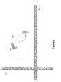
- FIG. 3geographically depicts the locator device entering a geo-fenced geographic area.
- FIG. 4geographically depicts the locator device leaving a geo-fenced geographic area.
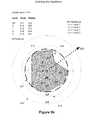
- FIGS. 5 a and 5 billustrate the confidence levels associated with a locator device exiting a circular and polygon geo-fenced geographic area, respectively.
- FIGS. 5 c and 5 dillustrate the confidence levels associated with a locator device entering a circular and polygon geo-fenced geographic area, respectively.
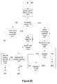
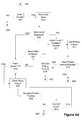
- FIG. 6 a - edescribes graphically an implementation of an illustrative embodiment of the border crossing detection algorithm.
- GPSGlobal Positioning System
- circuitry used through the disclosurecan include specialized hardware components such as graphics processors, and audio codecs for example.
- circuitrycan include microprocessors configured to perform function(s) by firmware or switches.
- circuitrycan include one or more general purpose processing units and/or multi-core processing units, etc., that can be configured when software instructions that embody logic operable to perform function(s) are loaded into memory, e.g., RAM and/or virtual memory.
- an implementermay write source code embodying logic and the source code can be compiled into machine readable code that can be processed by the general purpose processing unit(s).
- Geo-fence factorsmay comprise location uncertainty, geofence radius, and distance from current location point to geo-fence boundary point.
- a voting mechanismcomprising a vote of two may be implemented as follows. If a measured GPS location fix is determined to have crossed the geo-fence boundary, a second GPS location fix is immediately measured and if the second GPS location fix is also determined to have crossed the geo-fence boundary, the probability or confidence that the device has crossed the geo-fence boundary may be considered higher than the probability or confidence using only a single GPS location fix. The algorithm logic may then determine that the device has crossed the geo-fence boundary and an alert may be sent to the user. If the second fix determines that the device has not crossed the geo-fence boundary, then an alert will not be sent to the user and the algorithm may continue to the next step.
- the algorithmincludes several configurable parameters that are used to determine the confidence regarding crossing a boundary.
- the confidence thresholdis defined as a level of confidence that the device has crossed the geo-fence boundary. This value is a factor expressed in terms of distance from the edge of the geo-fence and reported location uncertainty. Calculation of a level of confidence is by the formula:
- the Haversine formulais an equation for calculating the great-circle distance between two points on a sphere from their longitudes and latitudes.
- the calculated confidence factorcan be tiered into four distinct levels:
- FIG. 1depicts an example network and functional entities in which various embodiments of the present disclosure may be implemented.
- the wireless device 101may include a GNSS (Global Navigation Satellite System) receiver configured to receive signals from GNSS satellites 102 .
- GNSSGlobal Navigation Satellite System
- An operative example of a GNSS 102is the United States NavStar Global Positioning System.
- the GNSS 102provides radio signaling 103 allowing calculation of highly accurate, three-dimensional location information, precision velocity and timing services by terrestrial receiver units.
- the wireless device 101may further communicate with the Location Device Management Network 123 via a wireless communications network 106 that supports wireless data communications 104 and a wired or wireless packet network 108 with dedicated or shared data connections 107 and 109 .
- the wireless data communications uplink 104 and downlink 105can be used for the downloading of assistance data from either the wireless communications network 106 or from the location server 111 via the intermediate data links 116 , 109 , and 107 , packet network 108 , and gateway 110 .
- Data routingmay be dependent on the capabilities of the wireless communications network 106 .
- the wireless communications network 106 downlink signal 105may also be used to enable mobile-based location techniques such as cell-ID, Advanced Forward Link Trilateration (AFLT) or Enhanced Cell ID (ECID) where broadcast information, the signal timing and/or power is used to calculate a position estimate.
- mobile-based location techniquessuch as cell-ID, Advanced Forward Link Trilateration (AFLT) or Enhanced Cell ID (ECID) where broadcast information, the signal timing and/or power is used to calculate a position estimate.
- the wireless location device 101 radio uplink transmissions 105may be used by network-based wireless location system(s) for localization when the GNSS signals 103 are blocked.
- the wireless device 101 radio uplink transmissions 105may also be used as part of a hybrid GNSS position estimate calculation.
- the packet network 108 as depictedmay be a generic digital packet network with transmission and routing facilities. Depending on the implementation with the wireless operator, the packet network 108 may be either private or public.
- the public packet network 115may be a generic digital packet network with transmission and routing facilities.
- the Internetis the prime example of this type of packet network.
- the Location Device Management Network 123may consist of functional software entities running on generic computer processing platforms. Although shown in this example as residents of a network cluster, the various entities within the Location Device Management Network 123 may reside on one or multiple servers.
- the internal digital interconnections 116 , 117 , and 118 within the Location Device Management Network 123may be implemented as local area connections, wide area connections or as virtual connections within a computing platform.
- the external digital connections 109 , 119 , and 120 associated with the Location Device Management Network 123are assumed by this model as implemented using industry defined packet WAN connections.
- the Gateway 110may be a selective firewall and communications router to protect and insulate the Location Device Management Network 123 from external threats.
- the Gateway 110under direction from the Device Management Server 112 , may also offer authentication and access control services.
- the Device Management Server 112may be the administrative, accounting, and logistical control entity for the Location Device Management Network 123 and wireless location devices 101 .
- the Email Server 113 and WWW portal 114are examples of commonly available applications.
- the Email Server 113 or the WWW portal 114may be used to communicate with landside (not shown) terminals or mobile terminal 122 when location events such as arrival, departures, border crossings or periodic location verifications occur.
- the mobile terminal 122may support a radio link 121 with the wireless communications network 106 which in turn may connect to the Public Packet Network 115 .
- the wireless location device 101may be a single purpose device attached to an object that is to be located or incorporated into another wireless device. In either case, and referring to FIG. 2 , the wireless location device 101 may include a main CPU module (the controller 204 ) and a Device Platform Services application 205 .
- a local Man-Machine-Interface (MMI) 201may be provided for local checks on device status and battery level.
- a power management subsystem 202configured by software or circuitry, may provide battery management, recharge facilities, and power level estimates for the local MMI 201 or remotely to the Device Management Server 112 .
- a local communications port 203may be used for reprogramming of application software or device configuration settings.
- Internal data links 211may provide interconnectivity between the various subsystems of the wireless location device 101 .
- Internal data buses 212may be used to connect the controller 204 and thus the Device Platform Services application 205 application to the local volatile memory 207 and non-volatile memory storage 206 .
- the Location Determination Subsystem 208may include the GNSS receiver and associated antenna.
- the Wireless Communications Subsystem 209may provide interfaces to the radio communications uplink 104 and downlink 105 .
- the Subscriber Information Module 210also known as a removable User Information Module (R-UIM) or Universal Subscriber Identity Module (USIM) is an industry standard module containing subscription information needed to enable the Wireless Communications Systems 209 to access the Wireless Communications Network 106 .
- R-UIMremovable User Information Module
- USIMUniversal Subscriber Identity Module
- the Wireless Communications Subsystem 209 and the Controller 204may be used to implement mobile-based location techniques.
- the applicationmay send a command to the Wireless Communications Subsystem 209 to detach the wireless data connection to the network and transition to a low-power idle mode.
- the applicationmay send a command to the Location Determination Receiver Subsystem 208 (e.g. the GPS module) to power down the module, thus eliminating power consumption by the Location Determination Receiver Subsystem 208 GPS module until the next location fix is requested by the application.
- the applicationmay send a command to the CPU module 204 to start the wakeup timer and transition the CPU module 204 to low-power sleep mode.
- a zone alert schedulemay specify the daily time intervals that the device may periodically determine a location (e.g. GPS position) fix and send an alert to a user if the device enters or exits the pre-defined geofence boundary or zone.
- the useraccessing the Device Management Server 112 via the WWW Portal 114 , may select a start and end time (e.g., from 7:00 am to 5:30 pm) for either (a) a single day that is recurring every week (e.g., every Monday), (b) selected multiple days of the week (e.g., Monday, Wednesday, Friday, Saturday, Sunday, etc.) that are recurring every week, or (c) all days of the week (i.e., Monday, Tuesday, Wednesday, Thursday, Friday, Saturday, Sunday).
- the selected start and end timemay be configured to recur every week.
- the recurring schedulemay continue until the user reconfigures the schedule or the schedule is terminated due to account termination.
- the schedulemay be implemented by the Device Platform Services 205 and stored in the nonvolatile local storage 206
- the network server(the device management server 112 ) may have the capability to configure the periodic rate (e.g., every 4 hours) at which the device will upload position fix logs to the server via a wireless data connection. Based on the configured rate, the device may set this value to a wakeup timer. When the timer expires, the device may wake up the application, read the position fix log from memory, set up a wireless data connection to the server, and send the position fix log to the server. The server may store the position fix log for each device in a database.
- the periodic ratee.g., every 4 hours
- the usermay select, for example, a position fix history tab for a selected device and time filter via the web server, whereupon the server may read the position fix data from the database for the selected time interval and display the positions to the user via a map display.
- the map displaymay, for example, depict position fix points and an arrow connecting each point based on position fix timestamps.
- FIG. 3illustrates an implementation of a geo-fenced boundary 302 which includes geographic entities 301 such as structures and roads.
- the wireless location device 101may cross the geo-fence boundary 302 from an initial position 303 outside the geo-fence boundary 302 .
- FIG. 4illustrates an implementation of a geo-fenced boundary 302 which includes geographic entities 301 such as structures and roads.
- the wireless location device 101crosses the geo-fence boundary 302 from an initial position 401 inside the geo-fence boundary 302 .
- FIG. 5 a and FIG. 5 billustrated are different confidence levels as they relate to the use case of a device exiting a geo-fence.
- a circular geo-fence 507has been defined around a central point 501 , the geo-fence having radius 502 .
- a confidence factor of Level 0may be defined as an area within a circle 505 around the central point 501 with a radius 510 .
- the arrow 522is shown to depict an example of a mobile device as it departs from the origin 501 , crosses the geofenced boundary and leaves the area.
- a confidence factor of Level 1may be defined as the area within an annulus between the described level 0 circle 505 and a second circle 506 around the central point 501 with a radius 503 .
- a confidence factor of Level 2may be defined as the area within an annulus between the described level 1 circle 506 and a second circle 508 around the central point 501 with a radius 504 .
- a confidence factor of Level 3is assigned to all areas 509 around the central point 501 with a radius 500 and outside the Level 0, Level 1, and Level 2 areas.
- a non-circular polygon 517has been designated as the geo-fenced area.
- the center-of-mass of the geo-fenced areamay be computed as 511 and the radius of the geo-fenced area's circular approximation has radius 512 , corresponding to the maximum offset between the computed center of mass 511 and the furthest edge of the polygon.
- the arrow 522is shown to depict an example of a mobile device as it departs from the center-of-mass 511 , crosses the geofenced boundary and leaves the area.
- a confidence factor of Level 0may be defined as an area within a circle 515 around the central point 511 with a radius 520 .
- a confidence factor of Level 1may be defined as the area within an annulus between the described level 0 circle 515 and a second circle 516 around the central point 511 with a radius 513 .
- a confidence factor of Level 2has been defined as the area within an annulus between the described level 1 circle 516 and a second circle 518 around the central point 511 with a radius 514 .
- a confidence factor of Level 3 519 around the central point 511 with a radius 521may be assigned to all areas outside the Level 0, Level 1, and Level 2 areas.
- FIG. 5 c and FIG. 5 dillustrated are different confidence levels as they relate to the use case of a device entering a geo-fence.
- a circular geo-fence 507has been defined around a central point 501 , the geo-fence having radius 502 .
- a confidence factor of Level 0may be defined as an area outside a circle 509 around the central point 501 with a radius 500 .
- the arrow 523is shown to depict an example of a mobile device as it enters the area, crosses the geofenced boundary and arrives at the origin 501 .
- a confidence factor of Level 1may be defined as the area inside an annulus between the described level 0 circle 509 and a second circle 508 around the central point 501 with a radius 504 .
- a confidence factor of Level 2may be defined as the area within an annulus between the described level 1 circle 508 and a second circle 506 around the central point 501 with a radius 503 .
- a confidence factor of Level 3is assigned to all areas 506 around the central point 501 with a radius 503 and inside the Level 0, Level 1, and Level 2 areas.
- a non-circular polygon 517has been designated as the geo-fenced area.
- the center-of-mass of the geo-fenced areamay be computed as 511 and the radius of the geo-fenced area's circular approximation has radius 512 , corresponding to the maximum offset between the computed center of mass 511 and the furthest edge of the polygon.
- the arrow 523is shown to depict an example of a mobile device as it enters the area, crosses the geofenced boundary and arrives at the center-of-mass 511 .
- confidence factor of Level 0may be defined as an area within a circle 519 around the central point 511 with a radius 521 .
- a confidence factor of Level 1may be defined as the area within an annulus between the described level 0 circle 519 and a second circle 518 around the central point 511 with a radius 514 .
- a confidence factor of Level 2has been defined as the area within an annulus between the described level 1 circle 518 and a second circle 516 around the central point 511 with a radius 513 .
- a confidence factor of Level 3 516 around the central point 511 with a radius 513may be assigned to all areas inside the Level 0, Level 1, and Level 2 areas.
- any geo-fenced arearepresented by any number of shapes and sizes. Shapes that may be approximated by a circle may efficiently be represented by determining a center of mass and a best fit circle.
- the presently disclosed methodsmay be applied to a geo-fenced area of any shape and size and an area of uncertainty of any shape and size.
- a geo-fenced areamay be rectangular while the area of uncertainty may be circular. In such a case the confidence levels may be determined as a function of the boundary of the rectangle and the circular area of uncertainty.
- FIGS. 6 a through 6 edepict an exemplary operational procedure for implementation of the border crossing detection algorithm.
- the algorithm depictedmay increase the probability of detection of movement into or out of the geographically defined area while decreasing the probability of false positives while at the same time, minimizing the number of position fixes calculated and reported.
- the on-board location capabilities of the wireless location device 101are limited to assisted GPS.
- the device application wake-up timer(local to the location device 101 ) expires, which wakes up the application.
- the Applicationrequests and receives the current position of the device from the GPS chipset (process 608 ).
- the GPS chipset receiverprocesses the GPS satellite signals, calculates the position, and returns the position to the Application.
- the Applicationretrieves the pre-defined geo-fence configuration data from the local device database 609 .
- the Applicationexecutes the geo-fence algorithm and the algorithm determines whether the device's position is inside or outside the pre-configured geo-fence boundary and the associated confidence level as to whether the device has crossed the geo-fence boundary.
- process 605the Application determines whether the confidence level is equal to the level 2 confidence level value. If the calculated confidence level from process 605 is not equal to the level 2 confidence value, then the process turns to process 606 . If the calculated confidence level from process 605 is equal to the level 2 confidence value, then the process turns to process 607 .
- the calculated confidence valueis equal to the level 2 confidence value, which results in a reset of the level 3 retry counter in process 610 .
- the Applicationperforms a validation check in process 611 . Due to the error uncertainty in the returned location, the device is in a “gray” area very close to the border of the geo-fence. Therefore, a state change is probable, but to minimize the probability of a false geo-fence boundary crossing alert/notification being sent to a user, the Application now requests additional position fixes from the device, based on the validation count, to increase the decision confidence. Because measurements in the level 2 decision process are in relation to the location uncertainty, a pre-configured location uncertainty upper limit is defined.
- the calculated level 2 position fixmay be erroneous and thus eliminated.
- the uncertainty thresholdis expressed in terms of a percentage with a default value of 99%. The uncertainty threshold is exceeded if the returned uncertainty is equal to or greater than the geo-fence radius. If the uncertainty threshold is exceeded in process 612 , the Application will log the error in process 613 and reset the polling interval in process 614 . If the location uncertainty threshold is not exceeded, the polling interval is reset in process 614 . If the polling interval timer expires, the process turns to process 608 to collect a new location estimate. If the polling interval has not expired wait for timer to expire and go to step 601 . If after performing the validation check in process 611 the validation count is greater than 0, the process turns to process 617 and the Application decrements the validation count by 1 and stores the new validation count value. The process then turns to process 602 , where the Application requests another position fix from the device and uses this position fix to determine the new state.
- the device application logicmay request a check of the prior state of the device position relative to the pre-configured geo-fence boundary.
- the Applicationchecks the prior state, which can be inside the geo-fence boundary, outside the geo-fence boundary, or unknown. If the prior state is unknown, then the process turns to process 621 and resets the level 2 validation counter. The process then turns to process 610 and resets the level 3 validation counter. The process then turns to process 622 and stores the new state.
- process 614the device has not yet crossed the threshold and therefore the state has not changed. If any other polling interval timers have expired, the process turns to process 608 to collect a location estimate.
- process 616the device CPU and Application is commanded to go into sleep mode until a device interval timer expires and wakes up the Application, whereupon the process will return to process 601 .
- the applicationturns to process 629 . If the confidence level is equal to level 3, the process turns to process 622 where the new state is stored.
- process 625the user pre-configured notification configuration is checked to determine if the user has requested a notification when the device exits or enters the geozone boundary.
- operationturns to process 621 where the level 2 validation counter is reset.
- the polling intervalis set.
- process 615it is determined whether the next polling interval timer has expired. If the next polling interval has not expired, the Application turns to process 616 and goes to sleep, waiting for the next polling interval timer to expire whereupon operation will turn to process 601 . If the next polling interval has expired, the Application turns to process 608 to collect a location estimate.
- operationturns to process 619 to check the position retry counter value. If the position retry counter value is equal to 0, the new state is sent to the server so that the server can send an “entry” or “exit” notification alert to the user via an SMS and/or Email delivery mechanism. If the position retry counter value is greater than 0, then operation turns to process 628 where the position retry counter is stored.
- the Applicationrequests and receives a new position fix. If there is an error in obtaining the position fix, operation turns to process 6219 If a successful position fix is returned, the Application goes to sleep and waits for the next sleep timer to expire to wake up the Application.
- the Applicationchecks the confidence level. If the confidence level equals level 1, the state has not changed, but the device is approaching the geozone boundary. Operation turns to process 631 , where the device is approaching the geo-fence boundary, taking into account the returned error uncertainty. However, because of the length of the default polling interval may be long, the Application may now reset the polling interval to 1 ⁇ 2 the previous default polling interval value. By decreasing the polling interval value, the device position is checked more frequently, thus reducing the notification time to the user if the device crosses the geo-fence boundary without changing the state. If the confidence level is not equal to level 1, the operation turns to process 614 and the default polling interval may be reset.
- Operationthen turns to process 621 and the level 2 validation counter is reset.
- process 610the level 3 position fix retry counter is reset.
- operationturns to process 615 where it is determined whether the next polling interval timer has expired. If the next polling interval has not expired, the Application turns to process 616 , goes to sleep, and waits for the next polling interval timer to expire whereupon operation will turn to process 601 . If the next polling interval has expired, the Application turns to process 608 to collect a location estimate.
Landscapes
- Engineering & Computer Science (AREA)
- Radar, Positioning & Navigation (AREA)
- Remote Sensing (AREA)
- Computer Networks & Wireless Communication (AREA)
- Signal Processing (AREA)
- Physics & Mathematics (AREA)
- General Physics & Mathematics (AREA)
- Position Fixing By Use Of Radio Waves (AREA)
- Mobile Radio Communication Systems (AREA)
Abstract
Description
- fenceCenterPoint—The latitude and longitude of the center of the geo-fenced circle or the center-of-mass of the geo-fenced polygon.
- currentLocation—The latitude and longitude of the locator device as calculated by the location system used.
- fenceRadius—The radius of the geo-fenced circle or the radius from the center-of-mass of the geo-fenced polygon.
- locationUncertainty—The returned horizontal uncertainty as calculated by the location system used
- Distance (e, f)—Distance as calculated by the Haversine formula
Δlat=lat2−lat1
Δlong=long2−long1
a=sin2(Δlat/2)+cos(lat1)*cos(lat2)*sin2(Δlong/2)
c=2*atan 2(√a, √(1−a))
d=R*c
- where R=earth's radius (mean radius=6,371 km)
Level 3—The device has crossed the geo-fence (state has changed). No further location determination is required. This level should immediately trigger a state change and if this geo-fence is configured for this type of state change, notify the server of that change. If the prior state (possible values in, out, or unknown) is unknown, store the state so the next polling interval can determine the correct level.Level 2—Due to the uncertainty in the location returned, the device is in a “gray” area very close to the border of the geo-fence (state change is probable). Further investigation must be performed to determine if the device has definitively entered or exited the zone. It is recommended that immediate consecutive location determination(s) (based on the validation count) occur to increase the confidence factor. If the prior state is unknown, this level is still valid as the current state should be determined before storing the state.Level 1—The device has not yet crossed the threshold (state has not changed), but is getting close (taking into account the returned uncertainty). No further location determinations need to be performed. However, because regular polling intervals may be far apart, then the interval is shortened (default is ½ the polling interval) while the device remains in this level of confidence percentage. If the prior state is unknown, store the state for the next polling interval.Level 0—The device is safely within/outside the geo-fence (state has not changed). Continue with regular polling intervals. If the prior state is unknown, store the state for the next polling interval.
uncertaintyThreshold=horizontalUncertainty/geo-fenceRadius
Claims (22)
Priority Applications (3)
| Application Number | Priority Date | Filing Date | Title |
|---|---|---|---|
| US12/276,246US8125332B2 (en) | 2008-11-21 | 2008-11-21 | Geo-fence with minimal false alarms |
| PCT/US2009/062625WO2010059392A1 (en) | 2008-11-21 | 2009-10-29 | Geo-fence with minimal false alarms |
| CA2744376ACA2744376A1 (en) | 2008-11-21 | 2009-10-29 | Geo-fence with minimal false alarms |
Applications Claiming Priority (1)
| Application Number | Priority Date | Filing Date | Title |
|---|---|---|---|
| US12/276,246US8125332B2 (en) | 2008-11-21 | 2008-11-21 | Geo-fence with minimal false alarms |
Publications (2)
| Publication Number | Publication Date |
|---|---|
| US20100127919A1 US20100127919A1 (en) | 2010-05-27 |
| US8125332B2true US8125332B2 (en) | 2012-02-28 |
Family
ID=42195753
Family Applications (1)
| Application Number | Title | Priority Date | Filing Date |
|---|---|---|---|
| US12/276,246Active2030-03-01US8125332B2 (en) | 2008-11-21 | 2008-11-21 | Geo-fence with minimal false alarms |
Country Status (3)
| Country | Link |
|---|---|
| US (1) | US8125332B2 (en) |
| CA (1) | CA2744376A1 (en) |
| WO (1) | WO2010059392A1 (en) |
Cited By (35)
| Publication number | Priority date | Publication date | Assignee | Title |
|---|---|---|---|---|
| US20100159955A1 (en)* | 2008-12-23 | 2010-06-24 | Motorola, Inc. | Method and Apparatus for Providing Location-Based Information |
| US20130171960A1 (en)* | 2011-12-29 | 2013-07-04 | Anil Kandregula | Systems, methods, apparatus, and articles of manufacture to measure mobile device usage |
| US20130318217A1 (en)* | 2009-08-21 | 2013-11-28 | Kevin R. Imes | Mobile energy management system |
| US8965401B2 (en) | 2012-05-01 | 2015-02-24 | Qualcomm Incorporated | Concurrent geofences with shared measurements |
| US9070275B1 (en) | 2014-02-21 | 2015-06-30 | Gearn Holdings LLC | Mobile entity tracking and analysis system |
| US9119034B2 (en) | 2013-11-21 | 2015-08-25 | At&T Mobility Ii Llc | Method and apparatus for determining a probability for a geo-fence |
| US9349104B2 (en) | 2013-09-25 | 2016-05-24 | Google Inc. | Learning geofence models directly |
| US9526437B2 (en) | 2012-11-21 | 2016-12-27 | i4c Innovations Inc. | Animal health and wellness monitoring using UWB radar |
| US20160381502A1 (en)* | 2013-05-23 | 2016-12-29 | Honeywell International Inc. | System and method with automatic radius crossing notification for global positioning system (gps) tracker |
| US9560482B1 (en) | 2015-12-09 | 2017-01-31 | Honeywell International Inc. | User or automated selection of enhanced geo-fencing |
| US9609478B2 (en) | 2015-04-27 | 2017-03-28 | Honeywell International Inc. | Geo-fencing with diagnostic feature |
| US9628951B1 (en) | 2015-11-11 | 2017-04-18 | Honeywell International Inc. | Methods and systems for performing geofencing with reduced power consumption |
| US9754492B2 (en) | 2014-07-08 | 2017-09-05 | The Toronto-Dominion Bank | Systems and methods for providing sensor-based location proximity detection and notification |
| US9860697B2 (en) | 2015-12-09 | 2018-01-02 | Honeywell International Inc. | Methods and systems for automatic adjustment of a geofence size |
| US9900174B2 (en) | 2015-03-06 | 2018-02-20 | Honeywell International Inc. | Multi-user geofencing for building automation |
| US9967391B2 (en) | 2015-03-25 | 2018-05-08 | Honeywell International Inc. | Geo-fencing in a building automation system |
| US10057110B2 (en) | 2015-11-06 | 2018-08-21 | Honeywell International Inc. | Site management system with dynamic site threat level based on geo-location data |
| US10063387B2 (en) | 2012-08-07 | 2018-08-28 | Honeywell International Inc. | Method for controlling an HVAC system using a proximity aware mobile device |
| US10149617B2 (en) | 2013-03-15 | 2018-12-11 | i4c Innovations Inc. | Multiple sensors for monitoring health and wellness of an animal |
| US10302322B2 (en) | 2016-07-22 | 2019-05-28 | Ademco Inc. | Triage of initial schedule setup for an HVAC controller |
| US10306403B2 (en) | 2016-08-03 | 2019-05-28 | Honeywell International Inc. | Location based dynamic geo-fencing system for security |
| US10317102B2 (en) | 2017-04-18 | 2019-06-11 | Ademco Inc. | Geofencing for thermostatic control |
| US10488062B2 (en) | 2016-07-22 | 2019-11-26 | Ademco Inc. | Geofence plus schedule for a building controller |
| US10516965B2 (en) | 2015-11-11 | 2019-12-24 | Ademco Inc. | HVAC control using geofencing |
| US10534331B2 (en) | 2013-12-11 | 2020-01-14 | Ademco Inc. | Building automation system with geo-fencing |
| US10605472B2 (en) | 2016-02-19 | 2020-03-31 | Ademco Inc. | Multiple adaptive geo-fences for a building |
| US10740718B2 (en) | 2014-12-01 | 2020-08-11 | Curbside, Inc. | Limited location tracking of a user device for local pickup |
| US10802469B2 (en) | 2015-04-27 | 2020-10-13 | Ademco Inc. | Geo-fencing with diagnostic feature |
| US10802459B2 (en) | 2015-04-27 | 2020-10-13 | Ademco Inc. | Geo-fencing with advanced intelligent recovery |
| US20240188540A1 (en)* | 2021-04-16 | 2024-06-13 | Save This Life, Inc. | Electronic system for multi-channel communication based real-time geolocation of an object |
| US12034400B2 (en) | 2020-12-22 | 2024-07-09 | 701x Inc. | Livestock management system |
| US12029197B1 (en) | 2023-02-01 | 2024-07-09 | 701x Inc. | Livestock location tracking system |
| US20240321073A1 (en)* | 2021-02-24 | 2024-09-26 | J Mann 8, LLC d/b/a Lilatech Systems | Systems and methods for tracking location |
| US12127531B2 (en) | 2023-02-01 | 2024-10-29 | 701x Inc. | Livestock age verification system |
| US12382932B2 (en) | 2023-06-07 | 2025-08-12 | 701x Inc. | Livestock monitoring system and methods of use |
Families Citing this family (81)
| Publication number | Priority date | Publication date | Assignee | Title |
|---|---|---|---|---|
| US20070060358A1 (en) | 2005-08-10 | 2007-03-15 | Amaitis Lee M | System and method for wireless gaming with location determination |
| US8616967B2 (en) | 2004-02-25 | 2013-12-31 | Cfph, Llc | System and method for convenience gaming |
| US7534169B2 (en) | 2005-07-08 | 2009-05-19 | Cfph, Llc | System and method for wireless gaming system with user profiles |
| US10510214B2 (en) | 2005-07-08 | 2019-12-17 | Cfph, Llc | System and method for peer-to-peer wireless gaming |
| CA2613333C (en)* | 2005-07-08 | 2012-04-10 | Cfph, Llc | System for wireless gaming with alerts |
| US8070604B2 (en) | 2005-08-09 | 2011-12-06 | Cfph, Llc | System and method for providing wireless gaming as a service application |
| US7644861B2 (en) | 2006-04-18 | 2010-01-12 | Bgc Partners, Inc. | Systems and methods for providing access to wireless gaming devices |
| US7549576B2 (en) | 2006-05-05 | 2009-06-23 | Cfph, L.L.C. | Systems and methods for providing access to wireless gaming devices |
| US8939359B2 (en) | 2006-05-05 | 2015-01-27 | Cfph, Llc | Game access device with time varying signal |
| US12136314B2 (en) | 2006-05-05 | 2024-11-05 | Cfph, Llc | Game access device with time varying signal |
| US9306952B2 (en) | 2006-10-26 | 2016-04-05 | Cfph, Llc | System and method for wireless gaming with location determination |
| US8510567B2 (en) | 2006-11-14 | 2013-08-13 | Cfph, Llc | Conditional biometric access in a gaming environment |
| US9411944B2 (en) | 2006-11-15 | 2016-08-09 | Cfph, Llc | Biometric access sensitivity |
| US8645709B2 (en) | 2006-11-14 | 2014-02-04 | Cfph, Llc | Biometric access data encryption |
| US9183693B2 (en) | 2007-03-08 | 2015-11-10 | Cfph, Llc | Game access device |
| US8031114B2 (en)* | 2008-03-31 | 2011-10-04 | International Business Machines Corporation | Infrastructure and method for geography based vehicle alert |
| US7973707B2 (en)* | 2008-06-11 | 2011-07-05 | 2201028 Ontario Inc. | Method for geofencing |
| US20110148626A1 (en)* | 2009-01-12 | 2011-06-23 | Acevedo William C | GPS Device and Portal |
| US20100203901A1 (en)* | 2009-02-11 | 2010-08-12 | Dinoff Robert K | Location-Based Services Using Geofences Generated from Learned Patterns of Movement |
| JP5487987B2 (en)* | 2010-01-15 | 2014-05-14 | 富士通株式会社 | Determination apparatus, program, determination method, and determination system |
| US20110178811A1 (en)* | 2010-01-19 | 2011-07-21 | Telenav, Inc. | Navigation system with geofence validation and method of operation thereof |
| US8369841B2 (en)* | 2010-02-16 | 2013-02-05 | Thaddeus John Kobylarz | Invoke facility service and its applications to compound wireless mobile communication services |
| US20110292230A1 (en)* | 2010-05-28 | 2011-12-01 | Winters Dustin L | Method for managing privacy of digital images |
| US20220296999A1 (en) | 2010-08-13 | 2022-09-22 | Cfph, Llc | Multi-process communication regarding gaming information |
| US8956231B2 (en) | 2010-08-13 | 2015-02-17 | Cfph, Llc | Multi-process communication regarding gaming information |
| EP4220424A1 (en)* | 2010-08-13 | 2023-08-02 | Cfph, Llc | Multi-process communication regarding gaming information |
| US8606260B2 (en) | 2010-08-18 | 2013-12-10 | Apple Inc. | Location-based profile |
| US8581997B2 (en) | 2010-10-28 | 2013-11-12 | Intellectual Ventures Fund 83 Llc | System for locating nearby picture hotspots |
| US8855677B2 (en)* | 2011-01-12 | 2014-10-07 | Telefonaktiebolaget Lm Ericsson (Publ) | Nodes and methods for positioning |
| US20120208549A1 (en)* | 2011-02-15 | 2012-08-16 | Microsoft Corporation | Automatic check-out upon location departure |
| CA2850250C (en) | 2011-03-07 | 2020-09-01 | Intelligent Imaging Systems, Inc. | Vehicle traffic and vehicle related transaction control system |
| US9880604B2 (en) | 2011-04-20 | 2018-01-30 | Microsoft Technology Licensing, Llc | Energy efficient location detection |
| US8971924B2 (en) | 2011-05-23 | 2015-03-03 | Apple Inc. | Identifying and locating users on a mobile network |
| US10715380B2 (en)* | 2011-05-23 | 2020-07-14 | Apple Inc. | Setting a reminder that is triggered by a target user device |
| WO2013028388A1 (en)* | 2011-08-19 | 2013-02-28 | 30 Second Software | Geo-fence entry and exit notification system |
| US20130091017A1 (en)* | 2011-10-05 | 2013-04-11 | DugaDuga.com, Inc. | Method And System for User Connections and Advertising Using Geographic Index of Affinity |
| US8725168B2 (en)* | 2011-10-17 | 2014-05-13 | Facebook, Inc. | Content surfacing based on geo-social factors |
| US8941489B2 (en) | 2011-10-20 | 2015-01-27 | Qualcomm Incorporated | Method and/or apparatus for geofence management |
| US9098866B1 (en)* | 2011-11-09 | 2015-08-04 | Michael Gurin | Dynamic personalization profile |
| WO2013090465A1 (en)* | 2011-12-12 | 2013-06-20 | Biketrak, Inc. | Bicycle theft monitoring and recovery devices |
| TWI627987B (en) | 2012-02-28 | 2018-07-01 | Cfph有限責任公司 | Method and apparatus of providing gameing service |
| EP2820630A4 (en)* | 2012-03-02 | 2016-03-23 | Telecomm Systems Inc | Location agent geofence |
| CN102595322B (en)* | 2012-03-19 | 2018-11-30 | Vid拓展公司 | Method and device for reminding user by using mobile terminal based on set position |
| KR101920001B1 (en)* | 2012-04-03 | 2018-11-19 | 삼성전자주식회사 | Status recognition apparatus and status recognition method |
| KR20150020171A (en) | 2012-05-17 | 2015-02-25 | 찬, 훈 맨 레나 | Information control system |
| US9113298B2 (en) | 2012-06-12 | 2015-08-18 | Telecommunication Systems, Inc. | Geofence with kalman filter |
| US20130340305A1 (en)* | 2012-06-13 | 2013-12-26 | nMode Solutions, Inc. | Tracking and monitoring of animals with combined wireless technology and geofencing |
| US9285484B2 (en)* | 2012-10-31 | 2016-03-15 | Qualcomm Incorporated | Method and apparatus for determining a position of a device relative to a virtual fence |
| US20140128093A1 (en)* | 2012-11-06 | 2014-05-08 | Qualcomm Incorporated | Portal transition parameters for use in mobile device positioning |
| CN105191361B (en) | 2013-02-22 | 2020-05-05 | 英特尔公司 | Geo-fence notification management |
| US20140274111A1 (en)* | 2013-03-14 | 2014-09-18 | Qualcomm Incorporated | Inter-device transfer of accurate location information |
| US9651673B2 (en)* | 2013-03-15 | 2017-05-16 | Qualcomm Incorporated | Energy conservation apparatus for geofence applications |
| US8874138B2 (en)* | 2013-03-15 | 2014-10-28 | Intel Corporation | Systems and methods for determining to use geo-fencing by using straight-line distances between locations |
| US9820231B2 (en) | 2013-06-14 | 2017-11-14 | Microsoft Technology Licensing, Llc | Coalescing geo-fence events |
| US9998866B2 (en)* | 2013-06-14 | 2018-06-12 | Microsoft Technology Licensing, Llc | Detecting geo-fence events using varying confidence levels |
| CN104244381B (en)* | 2013-06-17 | 2018-06-05 | 华为终端(东莞)有限公司 | Wake-up control method, device and terminal device |
| WO2014209374A1 (en)* | 2013-06-28 | 2014-12-31 | Intel Corporation | Geofencing |
| US9942718B2 (en)* | 2013-07-03 | 2018-04-10 | Qualcomm Incorporated | Methods and apparatuses for use in providing location parameters to mobile applications |
| US9866997B2 (en) | 2013-12-06 | 2018-01-09 | Mapquest, Inc. | Systems and methods for geo-location based message streams |
| NO336505B1 (en)* | 2013-12-20 | 2015-09-14 | Q Free Asa | Zone detection in a GNSS system |
| US9445230B1 (en)* | 2014-03-27 | 2016-09-13 | Pinger, Inc. | Automated arrival notifications |
| US9888347B1 (en)* | 2014-04-17 | 2018-02-06 | Google Inc. | Resolving location criteria using user location data |
| EP3162093A4 (en)* | 2014-06-24 | 2017-11-29 | Intel Corporation | Apparatus,system and method of geofencing |
| US9338598B2 (en)* | 2014-07-09 | 2016-05-10 | Samsung Electronics Co., Ltd | Geo-fence solver |
| JP6321222B2 (en)* | 2014-07-22 | 2018-05-09 | インテル コーポレイション | Systems and methods for geofence crossing-based control |
| US20160088546A1 (en)* | 2014-09-19 | 2016-03-24 | Intel Corporation | Regulation via geofence boundary segment crossings |
| US20160116274A1 (en)* | 2014-10-27 | 2016-04-28 | At&T Mobility Ii Llc | Mobility based location determination |
| US9497589B2 (en)* | 2014-11-25 | 2016-11-15 | International Business Machines Corporation | Systems and methods for managing sensitive data stored on a wireless computing device |
| CN105744473A (en) | 2014-12-08 | 2016-07-06 | 阿里巴巴集团控股有限公司 | Geo-fencing-based positioning method and device |
| US9794742B2 (en)* | 2015-07-01 | 2017-10-17 | Numerex Corp. | Method and system for locating a wireless tracking device |
| US9706355B1 (en)* | 2016-08-12 | 2017-07-11 | Contagious Atmosphere LLC | Systems and methods for automatically generating geofences based on property information |
| US20180106618A1 (en) | 2016-10-14 | 2018-04-19 | Westfield Retail Solutions, Inc. | Systems and methods to determine a location of a mobile device |
| CN106970396A (en)* | 2016-12-30 | 2017-07-21 | 重庆多道电子技术有限公司 | Determine the method that destination object is efficiently entering designated geographic area |
| CN106980128A (en)* | 2016-12-30 | 2017-07-25 | 重庆多道电子技术有限公司 | Data processing equipment |
| US9788160B1 (en)* | 2017-03-24 | 2017-10-10 | Symantec Corporation | Dynamic location tracking |
| WO2019077590A1 (en)* | 2017-10-20 | 2019-04-25 | Connected Cooking Solutions Private Limited | A system and method for controlling the cooking timer using iot devices |
| US10433107B1 (en)* | 2018-05-23 | 2019-10-01 | Futurewei Technologies, Inc. | System and method for enabling polygon geofence services on mobile devices |
| US10887267B2 (en) | 2018-09-12 | 2021-01-05 | International Business Machines Corporation | Intelligent notification routing and delivery |
| CN111132018B (en)* | 2018-11-01 | 2022-02-11 | 百度在线网络技术(北京)有限公司 | Track monitoring method and device for mobile equipment |
| CN109886999B (en)* | 2019-01-24 | 2020-10-02 | 北京明略软件系统有限公司 | Position determination method, device, storage medium and processor |
| EP3863310A1 (en)* | 2020-02-04 | 2021-08-11 | HERE Global B.V. | Checking desired triggering confidence of geo-fence |
Citations (12)
| Publication number | Priority date | Publication date | Assignee | Title |
|---|---|---|---|---|
| US5365451A (en) | 1991-12-09 | 1994-11-15 | Motorola, Inc. | Mobile unit tracking system |
| US6172640B1 (en) | 1999-06-18 | 2001-01-09 | Jennifer Durst | Pet locator |
| US6236358B1 (en) | 1999-06-18 | 2001-05-22 | Jennifer Durst | Mobile object locator |
| US6441778B1 (en) | 1999-06-18 | 2002-08-27 | Jennifer Durst | Pet locator |
| US6496775B2 (en)* | 2000-12-20 | 2002-12-17 | Tracer Net Corporation | Method and apparatus for providing automatic status information of a delivery operation |
| US20040039527A1 (en)* | 2000-12-20 | 2004-02-26 | Mcdonald Wesley E. | Method and apparatus for providing automatic status information of a vehicle operation cycle |
| US20040239558A1 (en)* | 2003-06-02 | 2004-12-02 | Geier George J. | Aiding location determinations in satellite positioning system receivers |
| US6980131B1 (en)* | 2000-10-24 | 2005-12-27 | @Road, Inc. | Targeted impending arrival notification of a wirelessly connected location device |
| US7171381B2 (en) | 1999-05-19 | 2007-01-30 | I.D. Systems, Inc. | System architecture and communications for an asset management system |
| US7327250B2 (en)* | 2003-07-25 | 2008-02-05 | Qualcomm Incorporated | System for providing a virtual vehicle boundary |
| US20080186166A1 (en)* | 2000-06-30 | 2008-08-07 | Zhou Peter Y | Systems and Methods For Monitoring and Tracking |
| US20090170528A1 (en)* | 2007-12-27 | 2009-07-02 | Trueposition, Inc. | Subscriber Selective, Area-based Service Control |
Family Cites Families (1)
| Publication number | Priority date | Publication date | Assignee | Title |
|---|---|---|---|---|
| CA2280378C (en)* | 1999-04-29 | 2009-05-26 | S&C Electric Company | Arrangements to detect and respond to disturbances in electrical power systems |
- 2008
- 2008-11-21USUS12/276,246patent/US8125332B2/enactiveActive
- 2009
- 2009-10-29WOPCT/US2009/062625patent/WO2010059392A1/enactiveApplication Filing
- 2009-10-29CACA2744376Apatent/CA2744376A1/ennot_activeAbandoned
Patent Citations (20)
| Publication number | Priority date | Publication date | Assignee | Title |
|---|---|---|---|---|
| US5365451A (en) | 1991-12-09 | 1994-11-15 | Motorola, Inc. | Mobile unit tracking system |
| US7171381B2 (en) | 1999-05-19 | 2007-01-30 | I.D. Systems, Inc. | System architecture and communications for an asset management system |
| US6480147B2 (en) | 1999-06-18 | 2002-11-12 | Jennifer Durst | Portable position determining device |
| US6172640B1 (en) | 1999-06-18 | 2001-01-09 | Jennifer Durst | Pet locator |
| US6441778B1 (en) | 1999-06-18 | 2002-08-27 | Jennifer Durst | Pet locator |
| US6236358B1 (en) | 1999-06-18 | 2001-05-22 | Jennifer Durst | Mobile object locator |
| US7209075B2 (en) | 1999-06-18 | 2007-04-24 | Pfizer, Inc. | Mobile object locator |
| US6518919B1 (en) | 1999-06-18 | 2003-02-11 | Jennifer Durst | Mobile object locator |
| US6421001B1 (en) | 1999-06-18 | 2002-07-16 | Jennifer Durst | Object locator |
| US6771213B2 (en) | 1999-06-18 | 2004-08-03 | Jennifer Durst | Object locator |
| US7113126B2 (en) | 1999-06-18 | 2006-09-26 | Pfizer, Inc. | Portable position determining device |
| US6859171B2 (en) | 1999-06-18 | 2005-02-22 | Danbeck Holdings, Inc. | Mobile object locator |
| US20080186166A1 (en)* | 2000-06-30 | 2008-08-07 | Zhou Peter Y | Systems and Methods For Monitoring and Tracking |
| US6980131B1 (en)* | 2000-10-24 | 2005-12-27 | @Road, Inc. | Targeted impending arrival notification of a wirelessly connected location device |
| US20040039527A1 (en)* | 2000-12-20 | 2004-02-26 | Mcdonald Wesley E. | Method and apparatus for providing automatic status information of a vehicle operation cycle |
| US6496775B2 (en)* | 2000-12-20 | 2002-12-17 | Tracer Net Corporation | Method and apparatus for providing automatic status information of a delivery operation |
| US6839020B2 (en) | 2003-06-02 | 2005-01-04 | Motorola, Inc. | Aiding location determinations in satellite positioning system receivers |
| US20040239558A1 (en)* | 2003-06-02 | 2004-12-02 | Geier George J. | Aiding location determinations in satellite positioning system receivers |
| US7327250B2 (en)* | 2003-07-25 | 2008-02-05 | Qualcomm Incorporated | System for providing a virtual vehicle boundary |
| US20090170528A1 (en)* | 2007-12-27 | 2009-07-02 | Trueposition, Inc. | Subscriber Selective, Area-based Service Control |
Non-Patent Citations (1)
| Title |
|---|
| PCT Notification of Transmittal of the International Search Report and the Written Opinion of the International Searching Authority mailed Dec. 23, 2009, issued in corresponding International Application No. PCT/US09/62625. |
Cited By (57)
| Publication number | Priority date | Publication date | Assignee | Title |
|---|---|---|---|---|
| US8391895B2 (en)* | 2008-12-23 | 2013-03-05 | Motorola Mobility Llc | Method and apparatus for providing location-based information |
| US20100159955A1 (en)* | 2008-12-23 | 2010-06-24 | Motorola, Inc. | Method and Apparatus for Providing Location-Based Information |
| US20130318217A1 (en)* | 2009-08-21 | 2013-11-28 | Kevin R. Imes | Mobile energy management system |
| US9800463B2 (en)* | 2009-08-21 | 2017-10-24 | Samsung Electronics Co., Ltd. | Mobile energy management system |
| US20130171960A1 (en)* | 2011-12-29 | 2013-07-04 | Anil Kandregula | Systems, methods, apparatus, and articles of manufacture to measure mobile device usage |
| US9020463B2 (en)* | 2011-12-29 | 2015-04-28 | The Nielsen Company (Us), Llc | Systems, methods, apparatus, and articles of manufacture to measure mobile device usage |
| US8965401B2 (en) | 2012-05-01 | 2015-02-24 | Qualcomm Incorporated | Concurrent geofences with shared measurements |
| US9219983B2 (en) | 2012-05-01 | 2015-12-22 | Qualcomm Incorporated | Mechanism to reduce missing breach detection in geofencing solution |
| US9451402B2 (en) | 2012-05-01 | 2016-09-20 | Qualcomm Incorporated | Geofence breach confidence |
| US10063387B2 (en) | 2012-08-07 | 2018-08-28 | Honeywell International Inc. | Method for controlling an HVAC system using a proximity aware mobile device |
| US11317608B2 (en) | 2012-11-21 | 2022-05-03 | i4c Innovations Inc. | Animal health and wellness monitoring using UWB radar |
| US10070627B2 (en) | 2012-11-21 | 2018-09-11 | i4c Innovations Inc. | Animal health and wellness monitoring using UWB radar |
| US9526437B2 (en) | 2012-11-21 | 2016-12-27 | i4c Innovations Inc. | Animal health and wellness monitoring using UWB radar |
| US10149617B2 (en) | 2013-03-15 | 2018-12-11 | i4c Innovations Inc. | Multiple sensors for monitoring health and wellness of an animal |
| US20160381502A1 (en)* | 2013-05-23 | 2016-12-29 | Honeywell International Inc. | System and method with automatic radius crossing notification for global positioning system (gps) tracker |
| US10448196B2 (en)* | 2013-05-23 | 2019-10-15 | Ademco Inc. | System and method with automatic radius crossing notification for global positioning system (GPS) tracker |
| US9349104B2 (en) | 2013-09-25 | 2016-05-24 | Google Inc. | Learning geofence models directly |
| US9473889B2 (en) | 2013-11-21 | 2016-10-18 | At&T Mobility Ii Llc | Method and apparatus for determining a probability for a geo-fence |
| US9119034B2 (en) | 2013-11-21 | 2015-08-25 | At&T Mobility Ii Llc | Method and apparatus for determining a probability for a geo-fence |
| US10768589B2 (en) | 2013-12-11 | 2020-09-08 | Ademco Inc. | Building automation system with geo-fencing |
| US10534331B2 (en) | 2013-12-11 | 2020-01-14 | Ademco Inc. | Building automation system with geo-fencing |
| US10591877B2 (en) | 2013-12-11 | 2020-03-17 | Ademco Inc. | Building automation remote control device with an in-application tour |
| US10712718B2 (en) | 2013-12-11 | 2020-07-14 | Ademco Inc. | Building automation remote control device with in-application messaging |
| US9342970B2 (en) | 2014-02-21 | 2016-05-17 | Arsite Technologies Llc | Mobile entity tracking and analysis |
| US9070275B1 (en) | 2014-02-21 | 2015-06-30 | Gearn Holdings LLC | Mobile entity tracking and analysis system |
| US9754491B2 (en) | 2014-07-08 | 2017-09-05 | The Toronto-Dominion Bank | Systems and methods for providing sensor-based location proximity detection and notification |
| US10176461B2 (en) | 2014-07-08 | 2019-01-08 | The Toronto-Dominion Bank | Systems and methods for providing sensor-based location proximity detection and notification |
| US9754492B2 (en) | 2014-07-08 | 2017-09-05 | The Toronto-Dominion Bank | Systems and methods for providing sensor-based location proximity detection and notification |
| US10740718B2 (en) | 2014-12-01 | 2020-08-11 | Curbside, Inc. | Limited location tracking of a user device for local pickup |
| US12271860B2 (en) | 2014-12-01 | 2025-04-08 | Rakuten Group, Inc. | Limited location tracking of a user device for local pickup |
| US9900174B2 (en) | 2015-03-06 | 2018-02-20 | Honeywell International Inc. | Multi-user geofencing for building automation |
| US9967391B2 (en) | 2015-03-25 | 2018-05-08 | Honeywell International Inc. | Geo-fencing in a building automation system |
| US10674004B2 (en) | 2015-03-25 | 2020-06-02 | Ademco Inc. | Geo-fencing in a building automation system |
| US10462283B2 (en) | 2015-03-25 | 2019-10-29 | Ademco Inc. | Geo-fencing in a building automation system |
| US10802459B2 (en) | 2015-04-27 | 2020-10-13 | Ademco Inc. | Geo-fencing with advanced intelligent recovery |
| US10802469B2 (en) | 2015-04-27 | 2020-10-13 | Ademco Inc. | Geo-fencing with diagnostic feature |
| US9609478B2 (en) | 2015-04-27 | 2017-03-28 | Honeywell International Inc. | Geo-fencing with diagnostic feature |
| US9826357B2 (en) | 2015-04-27 | 2017-11-21 | Honeywell International Inc. | Geo-fencing with diagnostic feature |
| US10057110B2 (en) | 2015-11-06 | 2018-08-21 | Honeywell International Inc. | Site management system with dynamic site threat level based on geo-location data |
| US9628951B1 (en) | 2015-11-11 | 2017-04-18 | Honeywell International Inc. | Methods and systems for performing geofencing with reduced power consumption |
| US10271284B2 (en) | 2015-11-11 | 2019-04-23 | Honeywell International Inc. | Methods and systems for performing geofencing with reduced power consumption |
| US10516965B2 (en) | 2015-11-11 | 2019-12-24 | Ademco Inc. | HVAC control using geofencing |
| US9860697B2 (en) | 2015-12-09 | 2018-01-02 | Honeywell International Inc. | Methods and systems for automatic adjustment of a geofence size |
| US10021520B2 (en) | 2015-12-09 | 2018-07-10 | Honeywell International Inc. | User or automated selection of enhanced geo-fencing |
| US9560482B1 (en) | 2015-12-09 | 2017-01-31 | Honeywell International Inc. | User or automated selection of enhanced geo-fencing |
| US10605472B2 (en) | 2016-02-19 | 2020-03-31 | Ademco Inc. | Multiple adaptive geo-fences for a building |
| US10302322B2 (en) | 2016-07-22 | 2019-05-28 | Ademco Inc. | Triage of initial schedule setup for an HVAC controller |
| US10488062B2 (en) | 2016-07-22 | 2019-11-26 | Ademco Inc. | Geofence plus schedule for a building controller |
| US10306403B2 (en) | 2016-08-03 | 2019-05-28 | Honeywell International Inc. | Location based dynamic geo-fencing system for security |
| US10317102B2 (en) | 2017-04-18 | 2019-06-11 | Ademco Inc. | Geofencing for thermostatic control |
| US12034400B2 (en) | 2020-12-22 | 2024-07-09 | 701x Inc. | Livestock management system |
| US12419275B2 (en) | 2020-12-22 | 2025-09-23 | 701x Inc. | Livestock management system |
| US20240321073A1 (en)* | 2021-02-24 | 2024-09-26 | J Mann 8, LLC d/b/a Lilatech Systems | Systems and methods for tracking location |
| US20240188540A1 (en)* | 2021-04-16 | 2024-06-13 | Save This Life, Inc. | Electronic system for multi-channel communication based real-time geolocation of an object |
| US12029197B1 (en) | 2023-02-01 | 2024-07-09 | 701x Inc. | Livestock location tracking system |
| US12127531B2 (en) | 2023-02-01 | 2024-10-29 | 701x Inc. | Livestock age verification system |
| US12382932B2 (en) | 2023-06-07 | 2025-08-12 | 701x Inc. | Livestock monitoring system and methods of use |
Also Published As
| Publication number | Publication date |
|---|---|
| WO2010059392A1 (en) | 2010-05-27 |
| US20100127919A1 (en) | 2010-05-27 |
| CA2744376A1 (en) | 2010-05-27 |
Similar Documents
| Publication | Publication Date | Title |
|---|---|---|
| US8125332B2 (en) | Geo-fence with minimal false alarms | |
| EP3482228B1 (en) | Method of scheduling wakeup events, method of operating a mobile transceiver, and devices configured for same | |
| AU2021200455B2 (en) | A location determination method and system | |
| US11800482B2 (en) | Mobile transceiver having route monitoring and method of operation | |
| US8395547B2 (en) | Location tracking for mobile computing device | |
| US20070120737A1 (en) | Method and system for providing location assistance information to a mobile station | |
| US9733361B2 (en) | Low power positioning techniques for mobile devices | |
| EP4070131A1 (en) | Tracking device | |
| CN113419266A (en) | Positioning method and device, electronic equipment and computer readable storage medium | |
| US20210258720A1 (en) | System and Method for Providing Location-Based Information | |
| US20210266697A1 (en) | Positioning technology selection for geo-fence | |
| US20210243549A1 (en) | Checking desired triggering confidence of geo-fence | |
| CN111352068A (en) | Equipment positioning method and device based on positioning system and positioning system | |
| KR102439737B1 (en) | Location tracking system and method using multiple gnss | |
| HK40032398A (en) | Equipment positioning method and device based on positioning system and positioning system | |
| KR20130055509A (en) | Method and apparatus for providing an alert on a user equipment entering an alerting area |
Legal Events
| Date | Code | Title | Description |
|---|---|---|---|
| AS | Assignment | Owner name:ZOOMBAK LLC, PENNSYLVANIA Free format text:ASSIGNMENT OF ASSIGNORS INTEREST;ASSIGNORS:CURRAN, DAVID;FANSHIER, RAND A.;DEMMEL, JESSE;REEL/FRAME:022291/0285 Effective date:20081124 | |
| AS | Assignment | Owner name:SECURUS ACQUISITION SUB, INC., NORTH CAROLINA Free format text:ASSIGNMENT OF ASSIGNORS INTEREST;ASSIGNOR:ZOOMBAK, LLC;REEL/FRAME:025852/0135 Effective date:20110218 | |
| AS | Assignment | Owner name:SECURUS ACQUISITION SUB, INC., NORTH CAROLINA Free format text:ASSIGNMENT OF ASSIGNORS INTEREST;ASSIGNOR:ZOOMBAK, LLC;REEL/FRAME:026050/0491 Effective date:20110218 | |
| AS | Assignment | Owner name:ZOOMBAK, INC., NORTH CAROLINA Free format text:CHANGE OF NAME;ASSIGNOR:SECURUS ACQUISITION SUB, INC.;REEL/FRAME:026072/0684 Effective date:20110221 | |
| STCF | Information on status: patent grant | Free format text:PATENTED CASE | |
| AS | Assignment | Owner name:FREEUS, LLC, UTAH Free format text:ASSIGNMENT OF ASSIGNORS INTEREST;ASSIGNOR:ZOOMBAK, INC.;REEL/FRAME:035748/0293 Effective date:20150526 | |
| FPAY | Fee payment | Year of fee payment:4 | |
| FEPP | Fee payment procedure | Free format text:PAYOR NUMBER ASSIGNED (ORIGINAL EVENT CODE: ASPN); ENTITY STATUS OF PATENT OWNER: SMALL ENTITY | |
| MAFP | Maintenance fee payment | Free format text:PAYMENT OF MAINTENANCE FEE, 8TH YR, SMALL ENTITY (ORIGINAL EVENT CODE: M2552); ENTITY STATUS OF PATENT OWNER: SMALL ENTITY Year of fee payment:8 | |
| AS | Assignment | Owner name:WEBSTER BANK, NATIONAL ASSOCIATION, MASSACHUSETTS Free format text:SECURITY INTEREST;ASSIGNOR:FREEUS, LLC;REEL/FRAME:053115/0372 Effective date:20200703 | |
| AS | Assignment | Owner name:CAPITAL ONE, NATIONAL ASSOCIATION, DELAWARE Free format text:SECURITY INTEREST;ASSIGNORS:BECKLAR, LLC;FREEUS, LLC;REEL/FRAME:058448/0438 Effective date:20211221 | |
| AS | Assignment | Owner name:BECKLAR, LLC, UTAH Free format text:RELEASE BY SECURED PARTY;ASSIGNOR:WEBSTER BANK, NATIONAL ASSOCIATION;REEL/FRAME:058972/0862 Effective date:20211221 Owner name:FREEUS, LLC, UTAH Free format text:RELEASE BY SECURED PARTY;ASSIGNOR:WEBSTER BANK, NATIONAL ASSOCIATION;REEL/FRAME:058972/0862 Effective date:20211221 | |
| MAFP | Maintenance fee payment | Free format text:PAYMENT OF MAINTENANCE FEE, 12TH YR, SMALL ENTITY (ORIGINAL EVENT CODE: M2553); ENTITY STATUS OF PATENT OWNER: SMALL ENTITY Year of fee payment:12 | |
| AS | Assignment | Owner name:VARAGON CAPITAL PARTNERS AGENT, LLC, AS ADMINISTRATIVE AGENT, ILLINOIS Free format text:SECURITY INTEREST;ASSIGNORS:FREEUS, LLC;BECKLAR, LLC;REEL/FRAME:069508/0196 Effective date:20241206 | |
| AS | Assignment | Owner name:FREEUS, LLC, UTAH Free format text:RELEASE BY SECURED PARTY;ASSIGNOR:CAPITAL ONE, NATIONAL ASSOCIATION;REEL/FRAME:069542/0981 Effective date:20241206 Owner name:BECKLAR, LLC, UTAH Free format text:RELEASE BY SECURED PARTY;ASSIGNOR:CAPITAL ONE, NATIONAL ASSOCIATION;REEL/FRAME:069542/0981 Effective date:20241206 | |
| AS | Assignment | Owner name:BECKLAR, LLC, UTAH Free format text:ASSIGNMENT OF ASSIGNORS INTEREST;ASSIGNOR:FREEUS, LLC;REEL/FRAME:071729/0332 Effective date:20250715 |