US8125216B2 - Methods and apparatus for angular position sensing using multiple quadrature signals - Google Patents
Methods and apparatus for angular position sensing using multiple quadrature signalsDownload PDFInfo
- Publication number
- US8125216B2 US8125216B2US12/342,382US34238208AUS8125216B2US 8125216 B2US8125216 B2US 8125216B2US 34238208 AUS34238208 AUS 34238208AUS 8125216 B2US8125216 B2US 8125216B2
- Authority
- US
- United States
- Prior art keywords
- differential
- sensor
- waveform
- sin
- output
- Prior art date
- Legal status (The legal status is an assumption and is not a legal conclusion. Google has not performed a legal analysis and makes no representation as to the accuracy of the status listed.)
- Active, expires
Links
Images


Classifications
- G—PHYSICS
- G01—MEASURING; TESTING
- G01D—MEASURING NOT SPECIALLY ADAPTED FOR A SPECIFIC VARIABLE; ARRANGEMENTS FOR MEASURING TWO OR MORE VARIABLES NOT COVERED IN A SINGLE OTHER SUBCLASS; TARIFF METERING APPARATUS; MEASURING OR TESTING NOT OTHERWISE PROVIDED FOR
- G01D5/00—Mechanical means for transferring the output of a sensing member; Means for converting the output of a sensing member to another variable where the form or nature of the sensing member does not constrain the means for converting; Transducers not specially adapted for a specific variable
- G01D5/12—Mechanical means for transferring the output of a sensing member; Means for converting the output of a sensing member to another variable where the form or nature of the sensing member does not constrain the means for converting; Transducers not specially adapted for a specific variable using electric or magnetic means
- G01D5/244—Mechanical means for transferring the output of a sensing member; Means for converting the output of a sensing member to another variable where the form or nature of the sensing member does not constrain the means for converting; Transducers not specially adapted for a specific variable using electric or magnetic means influencing characteristics of pulses or pulse trains; generating pulses or pulse trains
- G01D5/24471—Error correction
- G01D5/2448—Correction of gain, threshold, offset or phase control
- G—PHYSICS
- G01—MEASURING; TESTING
- G01D—MEASURING NOT SPECIALLY ADAPTED FOR A SPECIFIC VARIABLE; ARRANGEMENTS FOR MEASURING TWO OR MORE VARIABLES NOT COVERED IN A SINGLE OTHER SUBCLASS; TARIFF METERING APPARATUS; MEASURING OR TESTING NOT OTHERWISE PROVIDED FOR
- G01D5/00—Mechanical means for transferring the output of a sensing member; Means for converting the output of a sensing member to another variable where the form or nature of the sensing member does not constrain the means for converting; Transducers not specially adapted for a specific variable
- G01D5/12—Mechanical means for transferring the output of a sensing member; Means for converting the output of a sensing member to another variable where the form or nature of the sensing member does not constrain the means for converting; Transducers not specially adapted for a specific variable using electric or magnetic means
- G01D5/14—Mechanical means for transferring the output of a sensing member; Means for converting the output of a sensing member to another variable where the form or nature of the sensing member does not constrain the means for converting; Transducers not specially adapted for a specific variable using electric or magnetic means influencing the magnitude of a current or voltage
- G01D5/142—Mechanical means for transferring the output of a sensing member; Means for converting the output of a sensing member to another variable where the form or nature of the sensing member does not constrain the means for converting; Transducers not specially adapted for a specific variable using electric or magnetic means influencing the magnitude of a current or voltage using Hall-effect devices
- G01D5/145—Mechanical means for transferring the output of a sensing member; Means for converting the output of a sensing member to another variable where the form or nature of the sensing member does not constrain the means for converting; Transducers not specially adapted for a specific variable using electric or magnetic means influencing the magnitude of a current or voltage using Hall-effect devices influenced by the relative movement between the Hall device and magnetic fields
Definitions
- Hall effect modulesare used to generate sine and cosine signals from which angular position can be determined.
- Such sensorsuse digital processing to process the sine and cosine signals generated from the Hall cells. Due to analog to digital signal conversion and other factors, such digital processing imposes limitations on the speed and accuracy of angular position determination.
- part number AS5043 from Austria Microsystemsis an angular position sensor that digitally processes information from a Hall array using a coordinate rotational digital computer (CORDIC) that implements an iterative calculation for complex math with a lookup table.
- CORDICcoordinate rotational digital computer
- Other sensorsuse similar digital processing to implement various processing algorithms for computing position information.
- the quadrature relationship between the sinusoids used to determine angular positionis important for minimizing error.
- Ais the amplitude.
- One known approach for generating the necessary sine and cosine signalsis to rotate a bipolar disc magnet above two mechanically offset magnetic sensors. However, intentional or unintentional mechanical misalignment between the magnet and sensors can cause the input sinusoids to have an arbitrary phase relationship rather than the ideal quadrature of sine and cosine.
- the present inventionprovides a rotational sensor that generates a linear output from phase-shifted waveforms generated by magnetic sensors using analog signal processing.
- the sensoris provided on a single substrate. With this arrangement, an efficient and cost effective sensor is provided. While the invention is shown and described in exemplary embodiments as having particular circuit and signal processing implementations, it is understood that the invention is applicable to a variety of analog processing techniques, implementations, and algorithms that are within the scope of the invention.
- a sensorin one aspect of the invention, includes a signal generation module including a magnetic sensor to provide position information for generating first and second waveforms corresponding to the position information.
- An optional signal inversion modulecan be coupled to the signal generation module for inverting the first waveform to provide a first inverted waveform and for inverting the second waveform to provide a second inverted waveform.
- An analog signal processing modulecan be coupled to the optional signal inversion module for providing an algebraic manipulation of a subset of the first waveform, the second waveform, the first inverted waveform, and the second inverted waveform, from the signal inversion module and generating a linear position output voltage signal.
- Embodiments of the sensorcan include various features.
- the signal inversion modulecan output the first and second waveforms in a first region and output the first and second inverted waveforms in a second region, wherein the second region corresponds to a position range in which output would be non-linear without inversion of the first and second waveforms.
- a region indicator bitcan indicate position range in the first or second region. The first region can span about one hundred and eighty degrees.
- the first regioncan correspond to ⁇ sin( ⁇ )>cos( ⁇ ) where ⁇ sin( ⁇ ) refers to the inversion of the sine wave about an offset voltage, sin( ⁇ ) and cos( ⁇ ) embody the amplitudes and offsets associated with the sinusoids, and ⁇ indicates an angle of a rotating magnet in the magnetic sensor.
- the first regioncan correspond to a range for ⁇ of about 315 degrees to about 135 degrees.
- the signal processing modulecan include an analog multiplier.
- the sensorcan be provided on a single substrate.
- the sensorcan include a magnet having a plurality of pole-pairs to increase waveform frequency for reducing maximum angular error.
- a sensorin another aspect of the invention, includes a magnetic position sensing element to generate angular position information, a first signal generator to generate a first waveform corresponding to the angular position information, a second signal generator to generate a second waveform corresponding to the angular position information, wherein the first and second waveforms are offset by a predetermined amount.
- the sensorcan further include a first inverter to invert the first waveform for providing a first inverted waveform and a second inverter to invert the second waveform for providing a second inverted waveform, wherein the first and second waveforms are inverted about an offset voltage, and an analog signal processing module to generate a linear output signal from the first waveform, the second waveform, the first inverted waveform, and the second inverted waveform.
- the sensorcan include one or more of various features.
- the first and second waveformscan be used by the signal processing module in a first region and the first inverted waveform and the second inverted waveform being used in second region to generate the linear output signal.
- the first regioncan correspond to about 180 degrees of angular position for the position sensing element.
- a region indicatorcan indicate a first or second region of operation.
- a sensorin a further aspect of the invention, includes a signal generator means including a position sensor, a signal inversion means coupled to the signal generator means, and an analog signal processing means coupled to the signal inversion means to generate an output signal corresponding to angular position of the position sensor.
- the sensoris provided on a single substrate.
- a methodin another aspect of the invention, includes providing a signal generator module including a magnetic position sensing element, coupling a signal inversion module to the signal generator module, and coupling an analog signal processing module to the signal inversion module to generate a linear output signal corresponding to information from the position sensing element.
- the methodcan include one or more of providing the signal generator module, the signal inversion module, and the signal processing module on a single substrate, and generating first and second waveforms corresponding to the information from the position sensing element and inverting the first and second waveforms to generate the linear output signal.
- a sensorcomprises a magnet, first, second, third, and fourth sensor elements positioned in relation to the magnet, and an analog signal processing module to process output signals from the first, second, third, and fourth sensor elements and generate first and second differential signals for minimizing effects of positional misalignment of the first, second, third, and fourth sensor elements with respect to the magnet by maximizing a quadrature relationship of the first and second differential signals.
- a methodcomprises positioning first, second, third, and fourth sensor elements in relation to a magnet, and providing an analog signal processing module to process output signals from the first, second, third, and fourth sensor elements and generate first and second differential signals for minimizing effects of positional misalignment of the first, second, third, and fourth sensor elements with respect to the magnet by maximizing a quadrature relationship of the first and second differential signals.
- a vehiclecan comprises a sensor, comprising: a magnet, first, second, third, and fourth sensor elements positioned in relation to the magnet, and an analog signal processing module to process output signals from the first, second, third, and fourth sensor elements and generate first and second differential signals for minimizing effects of positional misalignment of the first, second, third, and fourth sensor elements with respect to the magnet by maximizing a quadrature relationship of the first and second differential signals.
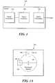
- FIG. 1is a block diagram of an exemplary analog angle sensor in accordance with the present invention
- FIG. 1Ais a pictorial representation of a Hall element that can form a part of a sensor in accordance with the present invention
- FIG. 2is a graphical depiction of modeled sine and cosine signals, an average of the sine and cosine signals, and an output signal based upon the relationships of Equation 1;
- FIG. 3is a graphical depiction of modeled sine, cosine, average, and output signals with an inverted region
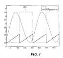
- FIG. 4is a graphical depiction showing a region indicator signal for linear and non-linear output regions
- FIG. 5is an exemplary circuit implementation of an analog angle sensor in accordance with the present invention.
- FIG. 6is a circuit diagram of a signal generation portion of the circuit of FIG. 5 ;
- FIG. 7is a circuit diagram of a signal inversion portion of the circuit of FIG. 5 ;
- FIG. 8is a circuit diagram of a signal processing portion of the circuit of FIG. 5 ;
- FIG. 9is a pictorial representation of an exemplary sensor package in accordance with the present invention.
- FIG. 9Ais a block diagram of a sensor having first and second dies
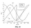
- FIG. 10is a graphical depiction of signals generated by an angle sensor in accordance with exemplary embodiments of the invention.
- FIG. 11is a pictorial representation of a ring magnet and sensors and sine and cosine signals
- FIG. 11Ais a pictorial representation of a multi-pole magnet in a donut shape that can generate sine and cosine signals;
- FIG. 12is a graphical depiction of signals generated by the arrangement of FIG. 11 ;
- FIG. 13is a pictorial representation of a ring magnet and sensors and sine and cosine signals
- FIG. 14is another pictorial representation of a ring magnet and sensors and sine and cosine signals
- FIG. 15is a graphical depiction of signals including ramps generated over one period of the sinusoidal signal
- FIG. 16is a graphical depiction of a first region decoder bit
- FIG. 17is a graphical depiction of a second region decoder bit
- FIG. 18is a circuit diagram of an exemplary implementation
- FIG. 19is a graphical depiction of a simulation of the circuit of FIG. 18 ;
- FIG. 20is a graphical depiction of complementary waveform averaging
- FIG. 21is a circuit diagram of an exemplary implementation of waveform averaging
- FIG. 22is a pictorial representation of two offset Hall elements and generated signals
- FIG. 23is a graphical depiction of a first signal processing step
- FIG. 24is a graphical depiction of a second signal processing step
- FIG. 25is a graphical depiction of a third signal processing step
- FIG. 26is a graphical depiction showing input gain factor, input angle and output angle
- FIG. 27is a circuit diagram showing an exemplary implementation
- FIG. 28is a circuit diagram showing further exemplary implementation of the circuit of FIG. 27 ;
- FIG. 29is a graphical depiction of a first signal processing step
- FIG. 30is a graphical depiction of a second signal processing step
- FIG. 31is a graphical depiction of a third signal processing step
- FIG. 32is a graphical depiction of a fourth signal processing step
- FIG. 33is a graphical depiction of a fifth signal processing step
- FIG. 34is a graphical depiction of a sixth signal processing step
- FIG. 35is a circuit diagram of an exemplary implementation
- FIG. 36is a graphical depiction of a simulated output for the circuit of FIG. 35 ;
- FIG. 37is a schematic representation of an AGC and/or AOA timing circuit.
- FIG. 38is a graphical depiction of signals in the circuit of FIG. 37 .
- FIG. 39is a schematic representation of a position sensor in accordance with exemplary embodiments of the invention.
- FIG. 40Ais a graphical depiction of sensor element output signals and FIG. 40B is a graphical depiction of differential signals from the output signals;
- FIG. 41Ais a graphical depiction of sensor element output signals with misalignment between the sensor elements and a magnet and FIG. 41B is a graphical depiction of differential signals from the output signals;
- FIG. 42Ais a graphical depiction of sensor element output signals with misalignment between the sensor elements and a magnet and FIG. 42B is a graphical depiction of differential signals from the output signals;
- FIG. 43is a flow diagram showing an exemplary sequence of steps for providing a sensor that uses differential signals in accordance with exemplary embodiments of the invention.
- FIG. 44is a graphical depiction of sinusoids with amplitudes gained to match and combined to generate sinusoids with a quadrature relationship in accordance with exemplary embodiments of the invention.
- FIG. 45is a graphical depiction of an output phase for various matching input amplitudes
- FIGS. 46A and 46Bare circuit representations of an exemplary processing operations.
- FIG. 47is a schematic representation of a gain control circuit having feedback in accordance with exemplary embodiments of the invention.
- FIG. 1shows an analog position sensor 100 having a signal generation module 102 to generate waveforms from magnetic sensors that are provided to an optional signal inversion module 104 , which generates inverted versions of the waveforms.
- a signal processing module 106implements an analog algebraic manipulation of the waveforms.
- the signal manipulation module 106generates a linear output voltage that is proportional to angular position.
- the sensoris provided on a single silicon substrate.
- FIG. 1Ashows a magnetic sensor shown as an exemplary Hall effect device 150 having a permanent magnet 152 with a first magnetic sensor 154 to generate a sine wave and a second magnetic sensor 156 placed ninety degrees from the first sensor to generate a cosine wave.
- the angular position ⁇ of the rotating magnet 152can be determined from the sine and cosine signals to provide a linear sensor output.
- the sensor circuithas a 360° sensing range and operates on a single power supply.
- the sensor outputis generated from the relationship set forth in Equation 1 below:
- outputA ⁇ ⁇ sin ⁇ ( ⁇ ) + offset 1 k ⁇ ( A ⁇ ⁇ sin ⁇ ( ⁇ ) + A ⁇ ⁇ cos ⁇ ( ⁇ ) + 2 ⁇ offset ) Eq ⁇ ⁇ ( 1 )
- Ais the amplitude of the generated sine and cosine signals
- offsetis the vertical offset of the sinusoidal signals with respect to ground
- kis any real number, where k affects the gain and vertical offset of the final sensor output.
- the value for kshould be set so that the mathematical value of the output falls within the desired operational range.
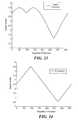
- FIG. 2shows modeled input sinusoidal signals and output for Equation 1.
- a sine wave 200 and cosine wave 202are shown as well as an average signal 204 of the sine and cosine signals.
- the output signal 206(sin/(sin/2+cos/2) is also shown. Note that sin/(sin/2+cos/2) embodies the amplitudes and offsets associated with the sinusoids as described by Equation 1.
- Equation 1produces an output signal 206 with a high degree of linearity in a first region of about 315° to 135° if the relationships in Equations 2 and 3 below hold:
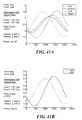
- Equation 1the model for Equation 1 can be modified so that the output signal has the same degree of linearity in both regions and is periodic over the two regions.
- this modificationis performed by inverting the waveforms if they fall within the range of 135°-315°(the second region), as shown in FIG. 3 .
- the sine waveform 200 ′, cosine waveform 202 ′, and average signal 204 ′are inverted in the range of 135° to 315°, which corresponds to ⁇ sin( ⁇ )>cos( ⁇ ) where ⁇ sin( ⁇ ) refers to the inversion of the sine wave about an offset voltage, sin( ⁇ ) and cos( ⁇ ) embody the amplitudes and offsets associated with the sinusoids as described by Equation 1.
- the inversion or second region of 135°-315°can be identified using a region indicator 250, which can be provided as a bit, that indicates whether ⁇ sin( ⁇ )>cos( ⁇ ), where ⁇ sin( ⁇ ) refers to the inversion of the sine wave about an offset voltage, sin( ⁇ ) and cos( ⁇ ) embody the amplitudes and offsets associated with the sinusoids.
- the modified model of Equation 1produces an output that is periodic over a range of 180°.
- the first and second regionscan be defined using the following:
- FIG. 5shows an exemplary circuit implementation for an analog position sensor 200 in accordance with the present invention.
- the sensor 200includes exemplary implementations for the signal generation, signal inversion, and signal processing modules 102 , 104 , 106 of FIG. 1 , which are described in detail below.
- FIG. 6shows one circuit implementation of a signal generation module 102 including first and second Hall effect devices 302 , 304 , each of which includes a Hall plate 306 and an amplifier 308 having offset trim and gain trim inputs.
- gain and offset trim valuescan be adjusted, such as by automatic gain control and/or automatic offset adjust.
- the first Hall effect device 302outputs a sin( ⁇ ) signal and the second Hall effect device 304 outputs a cos( ⁇ ) signal, where ⁇ represents a position of the rotating magnet.
- MRmagnetoresistor
- GMRgiant magnetoresistance
- AMRanisotrpic magnetoresistance
- a first signal inverter 310inverts the sin( ⁇ ) signal to provide a ⁇ sin( ⁇ ) signal (where ⁇ sin( ⁇ ) is inverted about an offset) and second signal inverter 312 inverts the cos( ⁇ ) signal to provide a ⁇ cos( ⁇ ) signal (where ⁇ cos( ⁇ ) is inverted about an offset).
- first signal inverter 310inverts the sin( ⁇ ) signal to provide a ⁇ sin( ⁇ ) signal (where ⁇ sin( ⁇ ) is inverted about an offset)
- second signal inverter 312inverts the cos( ⁇ ) signal to provide a ⁇ cos( ⁇ ) signal (where ⁇ cos( ⁇ ) is inverted about an offset).
- a comparator 314receives as inputs cos( ⁇ ) and ⁇ sin( ⁇ ) to generate a region indicator bit (inverted or non-inverted sin and cos signals as noted above).
- the comparator 314implements the ⁇ sin( ⁇ )>cos( ⁇ ) determination described above to generate the region indicator bit.
- the signal generation module 102also includes a regulated voltage supply 316 , e.g., 5V, and a bias reference voltage 318 , e.g., 2.5V. While a supply voltage of 5V is used in an exemplary embodiment, the particular voltage used can be varied while still meeting the relationships set forth in Equations (2) and (3) hold.
- a regulated voltage supply 316e.g., 5V
- a bias reference voltage 318e.g., 2.5V. While a supply voltage of 5V is used in an exemplary embodiment, the particular voltage used can be varied while still meeting the relationships set forth in Equations (2) and (3) hold.
- FIG. 7shows an exemplary signal inversion module 104 circuit implementation to invert the sinusoidal signals generated from the magnetic sensors 302 , 304 ( FIG. 6 ) in the 135°-315° (second) region.
- the original (sin( ⁇ ) and cos( ⁇ )) signals and the inverted signals ( ⁇ sin( ⁇ ) and ⁇ cos( ⁇ ))are provided as inputs to a 2-input analog multiplexer 350 .
- the comparator 314 outputwhich can correspond to the region indicator bit 250 of FIG. 4 , controls the output of the multiplexer 350 . That is, the region indicator bit 250 determines whether inverted or non-inverted signals are output from the analog multiplexer 250 .
- the multiplexer 250 outputscan be buffered with respective amplifiers 352 , 354 for input to the signal processing module 106 ( FIG. 8 ).
- the analog multiplier 400operates on a single supply and assumes that ground is equal to mathematical zero. It is understood that other circuit embodiments can operate with a variety of voltages, e.g., 0.5V, as “ground” to avoid effects associated ground variance, for example. Note that this division operation only requires two-quadrant division (or multiplication), since both incoming signals are assumed to be mathematically positive.
- the output from the analog multiplier 400is processed to provided gain and offset correction for output in a range of 0.5V to 4.5V, in the illustrated embodiment.
- circuits of FIG. 5can be implemented on a single substrate using processes and techniques well known to one of ordinary skill in the art
- Equation 1can be mathematically represented as set forth in Equation 4:
- Equation 5can be simplified as follows:
- Equation 8Multiply numerator and denominator by k/A to generate the result in Equation 8:
- Equation 11can be rewritten as in Equation 12:
- Equation 14Equation 14 can be rewritten as Equation 15:
- FIG. 9shows an exemplary sensor package 500 having an illustrative pinout of Vcc and Gnd with sin( ⁇ ) and cos( ⁇ ) pins, a region indicator, and position output signal. It will be appreciated that a variety of pinout configurations are possible.
- the sensor packageincludes a sensor on a single substrate 502 .
- the angle sensormay be desirable to provide an output of the angle sensor that is ratiometric with the supply voltage so that it can interface with the LSB (least significant bit) of various circuits, such as ADCs (analog to digital converters).
- ADCsanalog to digital converters
- Ratiometrycan be achieved by scaling the output of the division stage by Supply/5. It is understood that ratiometry can be achieved using other mechanisms.
- a sensorincludes AMR and circuitry on a single die.
- angle sensorscan have multiple dies, such as for GMR, AMR, GaAs, and various silicon Hall sensors.
- an angle sensorincludes multiple dies with a first die D 1 in a CMOS process for the circuits and a second die D 2 providing a different Hall plate doping for the sensor.
- Other embodimentsinclude one die with signal processing and two GaAs die and/or two MR die.
- the GMR dieact in a different plane of sensitivity so that the sensors need to be positioned appropriately, for example closer to the center of the axis of rotation.
- manufacturing costswill be reduced and steady state conditions will be reached sooner than in conventional devices.
- an angle sensorincreases sinusoidal frequency to provide higher output resolution. It is known that rotating a diametrically bipolar disc magnet above two 90° mechanically offset magnetic sensors will generate a sin/cosine signal pair as the output of the magnetic sensors. One 360° revolution of the magnet will correspond with one period of the sine and cosine signals. By increasing the frequency of the sinusoids over one 360° revolution, higher output resolution is achieved in angle sensing.
- a pair of sine/cosine signals for angle sensing applicationscan be generated by placing two magnetic sensors at a 90° mechanical offset around the center of a rotating diametrically bipolar disc magnet. Placing two Hall plates at a 90° mechanical offset around the center of a diametrically bipolar disc magnet produces a sine/cosine signal pair.
- Equation 21The maximum angular error of the output is calculated as follows in Equation 21:
- V ERROR_MAXMAX ⁇ ( ⁇ EXPECTED ⁇ ( ⁇ ) - V OUT ⁇ ( ⁇ ) - V OFFSET V FULL_SCALE ⁇ ⁇ RANGE ) Eq . ⁇ ( 21 )
- ⁇ EXPECTED ( ⁇ )is the expected angular output at a given angle ⁇
- V OUT ( ⁇ )is the expected output voltage of the magnetic sensor at a given angle ⁇
- V OFFSETis the offset of the output voltage
- V FULL — SCALEis the full scale voltage range of the output voltage
- ⁇ RANGEis the angular range of the output voltage ramp.
- the sine and cosine signals 600 , 602are shown as well as the output voltage V OUT ( ⁇ ) 604 .
- Equation 21the error is a function of the angular range of the output ⁇ RANGE .
- the maximum angular error (V ERROR — MAX )can be reduced if ⁇ RANGE is decreased while the other variables remain fixed.
- FIG. 11Ashows an alternative embodiment showing a multi-pole ‘donut’ magnet. Magnetization is radially outward from the center.
- first and second sensors 650 , 652are offset by ninety degrees on a ring magnet 654 having an odd number, i.e., three, of poles.
- FIG. 12graphically shows signals for the configuration of FIG. 11 .
- V ERROR_MAXMAX ⁇ ( ⁇ EXPECTED ⁇ ( ⁇ ) 3 - V OUT ⁇ ( ⁇ ) - V OFFSET V FULL_SCALE ⁇ ⁇ RANGE 3 ) Eq . ⁇ ( 22 )
- V ERROR_MAX1 3 ⁇ MAX ⁇ ( ⁇ EXPECTED ⁇ ( ⁇ ) - V OUT ⁇ ( ⁇ ) - V OFFSET V FULL_SCALE ⁇ ⁇ RANGE ) Eq . ⁇ ( 23 ) It is understood that increasing the frequency of the sinusoids with a ring magnet can be applied to any number of pole-pair combinations.
- a given ring magnetcan have several different possible sensor placements that generate the same sine( ⁇ ) and cos( ⁇ ) signals. While exemplary embodiments are shown and described as having a ring magnet, it is understood that other suitable devices can be used to generate waveforms.
- FIGS. 13 and 14show exemplary magnetic sensor placements for a ring magnet with two pole-pairs.
- FIG. 13shows a ring magnet 700 having first and second pole pairs.
- a first sensor 702is placed at an intersection of north/south, and the second sensor 704 is placed in the adjacent south pole for a separation of about forty-five degrees.
- FIG. 14shows a ring magnet 750 having a first sensor 752 at an intersection of north/south poles and a second sensor in the non-adjacent south pole for a separation of about 135 degrees.
- the resultant sine and cosines signalsare the same for both configurations.
- a region indicator bitcan be used to distinguish two adjacent output ramps over a single period of the sinusoidal input.
- a region indicator bitcan be used to distinguish the multiple output ramps over a 360 degree rotation of a ring magnet.
- a region indicator bitas input to a counter, one can determine the angular region of operation of the magnet.
- the countercan reset back to zero after cycling through all of the regions. This approach will work as long as the device starts in a known angular region (e.g. 0-90°, for the case of four regions of magnetization for the “magnet”) and the magnet is rotated in one direction. If the magnet rotates in both directions it is possible to use an up/down counter in conjunction with a direction detection algorithm to determine the region of operation. However, the device must start in a known angular region.
- Equation 24It is possible to calculate the number of output ramps generated by the ring magnet (i.e. number of distinguishable regions) using Equation 24 below with each ramp spanning an angular region given by Equation 25.
- Equation 24one can calculate that a ring magnet with two pole pairs corresponds to four output ramps over one complete rotation of the magnet. Each change in the bit state will correspond with a change in region of 90° (from Equation 25).
- the regions of operationcould be distinguished as set forth in Table 1 below
- a region indicator bitdistinguishes first and second ramps 802 , 804 generated over one period of the sinusoidal signal. If the region indicator bit is sent as input into a counter, then the counter can be used to distinguish the four 90° regions of operation over a 360° rotation of the magnet.
- the devicecould use an anisotropic magnetoresistance (AMR) sensor and/or a Giant Magnetoresistance (GMR) sensor.
- AMRanisotropic magnetoresistance
- GMRGiant Magnetoresistance
- the GMR elementis intended to cover the range of sensors comprised of multiple material stacks, for example: linear spin valves, a tunneling magnetoresistance (TMR), or a colossal magnetoresistance (CMR) sensor.
- the sensorincludes a back bias magnet to sense the rotation of a soft magnetic element, and/or target.
- signal processing circuitry required to increase the frequency of sinusoidal signals that are created by rotating a single pole magnet over Hall elementsprocesses the output voltage from the magnetic sensors and generates signals of greater frequency that can be used to obtain a better resolution when applied to an angle sensing algorithm, such as that described above in Equation 1.
- a linear output from the sine and cosine inputscan be generated by rotating a single bipolar magnet over two individual Hall elements.
- a change in y-volts in the outputdirectly corresponds to x degrees of rotation.
- increasing the frequency of the input sinusoidsin turn increases the output resolution by increasing the number of linear output ramps over a period of 360°.
- the outputsare decoded to distinguish the four ramps between 0-90°, 90°-180°, 180°-270°, and 270°-360°.
- the decodingcould be done using four bits, for example, as shown in Table 1, below.
- decoder bit onecan be generated as set forth below:
- FIG. 16shows a timing diagram with respect to the output 1000 for decoder bit one 1001 and FIG. 17 shows a timing diagram for decoder bit two 1002 .
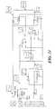
- FIG. 18shows an exemplary schematic implementation 1010 of the angle sensing mechanism described above.
- the circuit 1010includes a sine input 1012 and a cosine input 1014 .
- a region circuit 1016generates the decoder bit one.
- a algebraic circuit 1018implements equations 26 and 27 to provide sin(2 ⁇ ) and cos(2 ⁇ ) to an angle sensing circuit 1020 , such as the circuit shown in FIG. 5 .
- the algebraic circuit 1018generates component signals sin( ⁇ ) and cos( ⁇ ), which are multiplied by two and cos 2 ( ⁇ ) from which sin 2 ( ⁇ ) is subtracted.
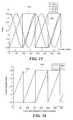
- FIG. 19shows a simulated output 1044 for the circuit of FIG. 18 .
- the simulated input sine 1040 and cosine 1042 signalshave frequencies of 1 kHz. Note that increasing the frequency to increase resolution can be achieved with any fraction of input signals. For example:
- the number of linear ramps in the outputis proportional to the frequency of the input; for the example using Equations 28 and 29 there would be three linear output ramps.
- Decoding circuitrycan distinguish the region of operation for each of the linear ramps.
- an angle sensing outputhas a nonlinear waveform that can be complemented with a second signal so that an average of the two signals has an enhanced degree of linearity.
- Equation 1is copied below:
- Equation 30One can choose a value for the value of the offset in Equation 30 that generates a nonlinear waveform. It is possible to then generate a second waveform with complimentary nonlinearity to the first. In one embodiment, this is performed by using a slightly modified version of Equation 30 as shown in Equation 31 below. The average of the first and second waveforms can have a higher degree of linearity than the best-case error of Equation 30 alone.
- Averaging the waveforms 1100 , 1102results in an output with a best-case maximum error of 0.029°. This is an order of magnitude less than without the inventive complementary waveform averaging.
- Equation 32The final output is described by Equation 32 below:
- Equation 321 2 ⁇ ( A ⁇ ⁇ sin ⁇ ( ⁇ ) A ⁇ ⁇ cos ⁇ ( ⁇ ) ⁇ offset + A ⁇ ⁇ sin ⁇ ( ⁇ ) Ak ⁇ ⁇ cos ⁇ ( ⁇ ) ⁇ offset ) Eq . ⁇ 32
- Ais the amplitude of sine and cosine
- offsetis the offset of cosine
- kis a scaling factor. Inversion is applied (i.e., minus sign) when cos( ⁇ ) ⁇ 0.
- FIG. 21 belowshows an exemplary implementation of Equation 32 in circuitry.
- Equation 33Note that the same averaging technique described here could be performed on two waveforms generated by Equation 30 that have different offsets, as shown in Equation 33.
- a circuitintegrates two magnetic sensors and the signal processing circuitry required to generate a third sinusoidal signal that is derived from the two sensor outputs. Using the three signals, the phase difference between two of the sinusoidal signals is trimmed. Trimming the phase difference between two sinusoidal signals can be advantageous in angle sensing, gear tooth sensing, and other applications. This feature is particularly advantageous when trimming out sensor misalignments as a result of:
- the conventional approach for generating a pair of sine/cosine signals required for angle sensing applicationsis to place two Hall plates at a 90° mechanical offset around the center of a rotating magnet.
- a disadvantage of this approachis that any misalignment in the 90° mechanical offset of the Hall plates results in a phase error between the sin and cosine signals.
- the primary source of mechanical misalignmentcomes from the end user's inability to precisely align the magnet above the device package. For example, a magnet placement misalignment of five mils can result in a phase error of up to about ⁇ 8.33°. Such a phase error translates to an angular error of approximately ⁇ 8° for arctangent algorithms. Phase error is one of the leading sources of error in angle sensing algorithms.
- phase difference between a Hall/MR generated sine/cosine signal pairis trimmed, as described in detail below. Note that this trimming may be difficult to implement when cos( ⁇ ) is constructed using ninety degree offset sensors.
- Equations 34, 35 and 36can be exploited to providing trimming in accordance with exemplary embodiments of the invention.
- first and second Hall signals S 1 and S 2are generated by respective Hall elements 1200 , 1202 .
- S 1A sin( ⁇ ), where A is some arbitrary gain. Note that it is assumed that A sin( ⁇ ) is a reference signal and therefore it has no phase error associated with it.
- the two generated signalscan be related to cosine using Equations 37, 38, and 39 below.
- phase-shifted cosine signalAfter constructing the phase-shifted cosine signal as above, the phase of the cosine can be trimmed.
- FIG. 26shows how the gain factor G affects the output phase ⁇ , for a few choices of ⁇ , which is the mechanical offset of S 2 with respect to S 1 .
- ⁇is the mechanical offset of S 2 with respect to S 1 .
- the steeper the output curve is around 90°the easier it is to fine tune ⁇ via changing the gain factor G.
- gain errorhas less impact on the final output angle. This is calculated in Table I, below, which summarizes the effect of the input phase ⁇ on the ability to construct a 90° phase shifted signal.
- the worst-case accuracy of the phase of cosinewould be ⁇ 0.440 assuming that ⁇ 10°.
- the next stepis to regulate the gain of C so that it matches A.
- This mathematical process of constructing cosineis implemented in exemplary circuitry in FIG. 27 .
- a cosine signalis generated from two input Hall signals A sin( ⁇ ) and AG sin( ⁇ + ⁇ ).
- Equation 41To phase shift A sin( ⁇ ) one can add another gain stage to the output of S 2 and then apply Equation 41.
- X and Yare gain factors and ⁇ is the angle shifted.
- a single waveformwhich can be sinusoidal, is used to generate a corresponding cosine signal.
- a linear outputcan be provided from two sinusoidal inputs, e.g., sine and cosine signals are generated from rotating a single pole magnet over two spatially phase shifted Hall elements.
- trigonometric identitiesare applied to a single sinusoidal input in order to construct its corresponding cosine signal.
- a triangle waveis generated that corresponds to the input sinusoid. The generation of this triangle wave does not require any memory of a previous state.
- Equation 43
- + ⁇ square root over ( A 2 ⁇ A 2 sin 2 ( ⁇ )) ⁇ Eq. (43) which provides rectified cos( ⁇ ).
- a true cos( ⁇ ) signalcannot be calculated directly because the squaring terms in this identity make all values positive. To calculate true cos( ⁇ ) requires an indicator bit that will invert the rectified signal at the appropriate points.
- a linear outputcan be calculated using a rectified sinusoidal signal.
- a sinusoidal inputcan be linearized by constructing its corresponding cosine signal.
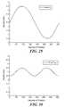
- a sinusoidal input A sin( ⁇ )is provided, as shown in FIG. 29 .
- the sinusoidis manipulated, as shown in FIG. 30 , to have the form A 2 sin 2 ( ⁇ ).
- can be calculated as shown in FIG. 31 .
- the next stepgains A sin( ⁇ ) and
- An inverted “cane” waveformis generated by adding GA sin( ⁇ ) to G
- the cane waveformwill be larger than the GA sin( ⁇ ) and G
- the “cane” waveformcan be divided by the rectified G
- the output waveformcorresponds with the peaks and troughs of the originating sinusoid.
- This procedure for linearizing a sinusoidcan be implemented in circuitry, such as the exemplary circuit shown in FIG. 35 . The output of the circuit is shown in the simulated results of FIG. 36 for the input sinusoid 1300 and the triangular output 1302 . For this example the input sinusoid has a frequency of 1 kHz.
- a method of identifying the negatively sloped portion of the outputis required. However, this would not be required for a 180 degree sensor.
- This identificationcan be in the form of an indicator bit that will invert the negatively sloped portion and distinguish the 0-180° region from the 180°-360° region.
- This indicator bitmay take the form of an additional magnetic field sensor that is used to identify the polarity of the magnetic field, i.e., north or south. Without this indicator bit the algorithm would only be capable of a range of 0-180°. Notice that the output differs from the mechanism of Equation 1 in that the phase of the output has a ⁇ 90° phase shift rather than a ⁇ 45° phase shift. The phase shift for an embodiment of Equation 1 considered 0° to be the point where the output was at a minimum.
- the gain and offset of the input sinusoidsis controlled in order to reduce the final output error.
- Automatic Gain Control (AGC) and Automatic Offset Adjust (AOA)can be applied to the angle sensing embodiments described above.
- AGCAutomatic Gain Control
- AOAAutomatic Offset Adjust
- one embodimentuses offset adjustment DACs (digital-to-analog) and gain cell transconductors that accept an input current from a current DAC to control the gain of an amplifier.
- AGCAutomatic Gain Control
- AOAAutomatic Offset Adjust
- This method of gain controlis effective for signals with zero offset and matching gains, and it can be used in conjunction with other AGC methods.
- gain and offsetcan be trimmed at end of line test and/or at customer final test, for example. It can also be adjusted at device power up or change dynamically during running mode.
- the devicecan have a calibrate pin that enables or disables the adjust mode.
- This pincould also control the update speed in which the AGC and AOA corrections are applied to the output.
- the update frequencycould be controlled by a timing mechanism or correspond with the falling edge transition of the algorithm's final output ramp.
- FIGS. 37 and 38show an exemplary technique for controlling the speed of the AGC and AOA during running mode via a timing mechanism.
- An external capacitor C on a calibrate pin CALcharges the central node.
- V REFWhen the voltage on the capacitor C reaches V REF , a comparator CO trips and discharges the capacitor.
- the comparator CO outputwill pulse high momentarily.
- AOA and AGC correctionscan be updated whenever the comparator pulses high. Choosing different size capacitors can control the speed of the comparator pulses. Tying the CAL pin LOW will shut off the dynamic updating mode.
- an angular sensoruses first and second quadrature signals from frequency independent sinusoids. With this arrangement, the accuracy of the sensor can be enhanced.
- Exemplary embodiments of the invention described below in detaildisclose how to obtain first and second quadrature signals from frequency independent sinusoids. Further exemplary embodiments include utilization of these signals with an example of automatic gain control (AGC) techniques.
- AGCautomatic gain control
- Known angle-sensing algorithmsgenerate a linear output ramp using two input sinusoidal signals. These algorithms rely on a 90° phase relationship between the two input sinusoids and are intolerant to slight phase changes from the ideal. Generating first and second sinusoidal signals with enhanced quadrature helps minimize the error in angle sensing algorithms and is useful for automatic gain control (AGC).
- AGCautomatic gain control
- FIG. 39shows an exemplary sensor embodiment 2000 for creating sinusoids that have a nearly quadrature relationship over misalignment.
- Differential signals generated from four Hall elements 2002 a - d arranged with respect to a rotating magnet 2004are utilized as described below.
- the four Hall elements 2002are oriented in a square configuration facing the disc magnet 2004 . Assume that the center point CP between the four Hall elements 2002 is aligned with the center C of the disc magnet 2004 .
- the first Hall element 2002is at the TOP
- the second Hall element 2002 bis RIGHT
- the third Hall element 2002 cis BOTTOM
- the fourth Hall element 2002 dis LEFT.
- the sensor 2000further includes a signal processing module 2008 for performing at least a portion of the signal processing described below in detail.
- FIG. 40Ashows the signals T, B, L, R from each of the four Hall elements 2002 a (TOP), 2002 b (RIGHT), 2002 c (BOTTOM), 2002 D (LEFT) where the Hall elements are centered, i.e., not misaligned.
- the first input sinusoidhas an amplitude of 1.39 Vpp and the second input sinusoid has an amplitude of 1.66 Vpp for a ratio of 0.8082.
- the first input signalhas an offset of 2.489 V and the second input signal has an offset of 2.501 V with a phase of 84.32 degrees.
- FIG. 41Ashows four Hall elements signals T, B, L, R for a misalignment of 1 mm up and 1 mm Left. It is understood that alignment is determined from a center of the magent 2004 ( FIG. 40 .) and the center of the four elements 2002 .
- FIG. 41Bshows the first and second signals Sig 1 , Sig 2 derived from the Hall elements signals T, B, L, R.
- FIG. 42Ashows four Hall element signals T, B, L, R for a misalignment of 1 mm up and 2 mm left.
- FIG. 42Bshows the resultant signals Sig 1 , Sig 2 .
- output signals from four sensor elementscan be used to generate differential signals having a substantially quadrature relationship to reduce accuracy degradation from mechanical misalignment of the sensor elements with respect to a magnet.
- FIG. 43is a flow diagram showing an exempalry sequence of steps for a differential sensor in accordance with exemplary embodiments of the invention.
- step 2100misalignment between is determined.
- step 2102signals from the Hall elements, such as the four Hall elements 2002 a (TOP), 2002 b (RIGHT), 2002 c (BOTTOM), 2002 D (LEFT), shown in FIG. 39 , are received.
- FIG. 9shows an exemplary package type in which an inventive sensor can be provided.
- exemplary embodimentscreate sinusoids with a quadrature relationship by gaining the amplitudes of first and second sinusoids to match, and then adding and subtracting the two signals.
- SIG ⁇ ⁇ 1IN ⁇ ⁇ 1 - IN ⁇ ⁇ 2 2 ( Eq ⁇ ⁇ 50 )
- SIG ⁇ ⁇ 2IN ⁇ ⁇ 1 + IN ⁇ ⁇ 2 2 ( Eq ⁇ ⁇ 51 )
- FIG. 44An example of the above relationship is shown in FIG. 44 for signals IN 1 , IN 2 , SIG 1 , SIG 2 .
- IN 13 sin( ⁇ )
- IN 23 sin( ⁇ +150°).
- the resulting sinusoids SIG 1 and SIG 2have mismatched amplitudes and a 90° phase difference.
- FIG. 45shows output phases for various changes in matching input amplitudes (see Eq 46 and Eq 47).
- the x-axisrepresents the input phase difference, ⁇ .
- the quadrature relationshipholds with a relatively tight tolerance for most input phase differences using this technique.
- FIGS. 46A and 46Bshow exemplary circuit implementations for the mathematical operations shown in Eq 50 and Eq 51.
- FIG. 46Ashows a resistive divider
- FIG. 46Bshows a wheatstone bridge. It is understood that a wide variety of alternative implementations will be readily apparent to one of ordinary skill in the art. For example, op-amp circuitry can be readily configured to provide a desired result.
- the output quadrature sinusoidal signalswill not necessarily have matching amplitudes.
- the signalscan be trimmed for matching amplitudes before they are input into an angle sensing algorithm.
- the approaches described abovecan be used separately or in conjunction with each other to produce sinusoids with a quadrature relationship.
- the quadrature signalscan be trimmed to have matching gains and used as inputs for angle-sensing processing. These processed signals are useful for automatic gain control (AGC) circuitry.
- AGCautomatic gain control
- A⁇ square root over ( A 2 sin 2 ⁇ +A 2 cos 2 ⁇ ) ⁇ (Eq 54)
- a 2A 2 sin 2 ⁇ +A 2 cos 2 ⁇ (Eq 55) where A is the amplitude, and ⁇ is the magnetic angle of rotation.
- the above trigonometric relationshipsare used to designate one input signal as “A sin ⁇ ” and one input signal as “A cos ⁇ ” and calculate A directly using Eq 54 above.
- Squaring, addition, and square root blockscan be used to calculate ⁇ square root over (A 2 sin 2 ⁇ +A 2 cos 2 ⁇ ) ⁇ .
- the value of Acan be compared with a reference voltage, and the amplitudes of A sin ⁇ and A cos ⁇ can be scaled using feedback circuitry.
- the above trigonometric relationshipsare used to find the value of A 2 using squaring and addition blocks to calculate A 2 sin 2 ⁇ +A 2 cos 2 ⁇ (from Eq 55).
- the value of A 2can be compared with a reference voltage, and the amplitudes of A sin ⁇ and A cos ⁇ can be scaled using feedback circuitry.
- This second approacheliminates the need for a square root block in the circuit implementation (see FIG. 47 ).
- FIG. 47shows an exemplary circuit 3000 having a gain control circuit 3002 in accordance with the invention.
- AGC processingcalculates A 2 value with V REF signal.
- Signal A sin ⁇is squared 3004
- Signal A cos ⁇is squared 3006
- these signalsare summed 3008 to provide signal A 2 to the gain control circuit 3002 .
- a reference voltage Vref, signal A sin ⁇ , and signal A cos ⁇are provided to the gain control circuit 3002 , which outputs Ak sin ⁇ and Ak cos ⁇ for feedback to A sin ⁇ and A cos ⁇ respectively.
- the gain control circuit 3002increases or decreases the value of k until A 2 equals Vref.
- Exemplary embodiments of the inventionprovide advantages over known sensor implementations. For example, a 90° output phase relationship nearly holds for arbitrary misalignment using a head-on magnet configuration and four Hall element implementation. In addition, the 90° output phase relationship is valid for most values of the input phase, ⁇ with add/subtract techniques. The nearly quadrature relationship will continue to hold as long as the two input signals have matching amplitudes. Further, the output phase is only a function of matching input amplitudes with add/subtract technique, and is therefore independent of input phase or mismatched input offsets.
Landscapes
- Physics & Mathematics (AREA)
- General Physics & Mathematics (AREA)
- Transmission And Conversion Of Sensor Element Output (AREA)
Abstract
Description
where θ indicates an angle of a rotating magnet in the magnetic sensor, offset is a vertical offset of the first and second waveforms with respect to ground, A is an amplitude of the first and second waveforms, and k is a real number affecting gain and vertical offset of the output. The signal processing module can include an analog multiplier. The sensor can be provided on a single substrate. The sensor can include a magnet having a plurality of pole-pairs to increase waveform frequency for reducing maximum angular error.
where output is the sensor output, A is the amplitude of the generated sine and cosine signals, offset is the vertical offset of the sinusoidal signals with respect to ground, and k is any real number, where k affects the gain and vertical offset of the final sensor output. In general, the value for k should be set so that the mathematical value of the output falls within the desired operational range.
In a second region of 135°-315°, the input sinusoids are inverted around the offset voltage as compared to the first region. The illustrated model assumes that A=2 volts, offset=2.5 volts, and k=2.
- if −sin(θ)>cos(θ)
- output region=0°-180° (first region where θ ranges from 315° to 135°)
- else
- output region=180°-360° (second region where θ ranges from 135° to 315°)
Alternatively, theregion indicator 250 can be used to vertically shift up the sensor output of the 180°-360° or second region to create a linear ramp. The magnitude of the vertical shift is dependent on the variable k.
- output region=180°-360° (second region where θ ranges from 135° to 315°)
- if −sin(θ)>cos(θ)
The point between the resistors R1, R2 provides (sin(θ)+cos(θ))/2. This signal is buffered and input to the
where output is the sensor output, A is the amplitude of the generated sine and cosine signals, offset is the vertical offset of the sinusoidal signals with respect to ground, and k is any real number, where k affects the gain and vertical offset of the final sensor output.
or, as in
The inversion is then applied, i.e., the “−” term when:
Insert an add and subtract cos(θ) term in the numerator as shown Equation (9):
Insert an add and subtract sin(θ) term in the numerator per Equation 10.
Factor out sin(θ) from the “k sin(θ)−sin(θ)” term in the numerator as in Equation 11.
in both the numerator and the denominator. Equation 11 can be rewritten as in Equation 12:
Since sin(θ)+cos(θ)=√{square root over (2)} sin(θ+45°) and sin(θ)−cos(θ)=√{square root over (2)} sin(θ−45°), as is well known, Equation 14 can be rewritten as Equation 15:
Dividing the numerator and denominator of the right side of the equation by √{square root over (2)} results in the relationship of Equation 16:
Note that the sinusoidal term in the numerator, sin(θ−45°), differs from the sinusoidal term in the in the denominator, sin(θ+45°), by a phase of 90°. Because of this, one can replace the numerator and denominator with sin(θ) and cos(θ) respectively, as shown in Equation 17 below:
This changes the inversion point (i.e. application of the “−” term) to: 0>cos(θ). Also, the phase of the output is now aligned identically with arctangent rather than being out of phase with arctangent by 45°.
Since the variables A and offset no longer represent the real gain and offset of the sinusoids one should identify this constant as a number, which can be referred to as b. Rewriting again results in the relationship set forth in Equation 18:
The linearity of the output depends upon the value of the constant term. The previous example showed that A=2 and offset=2.5V. In a straightforward ‘guess’, the ideal constant term of b is approximately equal to 1.7678. The linearity of the output can be improved slightly by varying the value of b. It will be appreciated that the relationship of Equation 18 can be scaled as desired, such as to fit the original specifications above. If sin(θ) and cos(θ) have some gain, A, then the constant b must also become a function of A as set forth in Equation 19:
It is possible to know the value of A by using automatic gain control or using the well known trigonometric relationship of Equation 20:
A=√{square root over ((Asin(θ))2+(Acos(θ))2)}{square root over ((Asin(θ))2+(Acos(θ))2)} Eq. (20)
where θEXPECTED(θ) is the expected angular output at a given angle θ, VOUT(θ) is the expected output voltage of the magnetic sensor at a given angle θ, VOFFSETis the offset of the output voltage, VFULL
It is understood that increasing the frequency of the sinusoids with a ring magnet can be applied to any number of pole-pair combinations. Note that a given ring magnet can have several different possible sensor placements that generate the same sine(θ) and cos(θ) signals. While exemplary embodiments are shown and described as having a ring magnet, it is understood that other suitable devices can be used to generate waveforms.
| TABLE 1 |
| Region of Operation |
| Counter State | Region of | ||
| 0 | 0-90° | ||
| 1 | 90°-180° | ||
| 2 | 180°-270° | ||
| 3 | 270°-360° | ||
sin(2θ)=2 sin(θ)cos(θ) Eq. (26)
cos(2θ)=cos2(θ)−sin2(θ) Eq. (27)
If the doubled frequency signals produced by Equations 26 and 27 are sent as inputs into the angle sensing mechanism of
| TABLE 1 |
| Decoder Bits To Distinguish the Region of Operation |
| of Each of the Output Ramps |
| Angular Region | Value of | Value of |
| 0-90° | LOW | LOW |
| 90°-180° | LOW | HIGH |
| 180°-270° | HIGH | LOW |
| 270°-360° | HIGH | HIGH |
In an exemplary embodiment, decoder bit one can be generated as set forth below:
- if sin(θ+22.5°)>offset
Bit 1=LOW
- else
Bit 1=HIGH
where offset is the vertical offset of the sinusoidal signals with respect to mathematical zero (e.g. ground). Note that the complexity in determining decoder bit one is a result of the −45° phase shift in the output of the previous angle sensing relationship. It is possible to change the −45° phase shift, thus simplifying the comparison process, by using a different form of the algorithm than described inEquation 1.
- if sin(θ+22.5°)>offset
- if −sin(2θ)>cos(2θ)
Bit 2=LOW elseBit 2=HIGH
- if −sin(2θ)>cos(2θ)
where output is the sensor output, A is the amplitude of the generated sine and cosine signals, offset is the vertical offset of the sinusoidal signals with respect to ground, and k is any real number. Where the waveforms are inverted in a region to achieve the same degree of linearity over 360 degrees (see Equation 4), the minus sign is applied if −sin(θ)>cos(θ). Performing algebraic manipulations on
where output is the sensor output, A is the amplitude of the generated sine and cosine signals, and offset is the vertical offset of cosine with respect to ground. The minus sign is applied if cos(θ)<0. Recall that the output of
where k is a scaling factor. Note that A and offset have the same value for both equations. Choosing the values of k=0.309 and offset=1.02A produce the waveforms shown in
where A is the amplitude of sine and cosine, offset is the offset of cosine, and k is a scaling factor. Inversion is applied (i.e., minus sign) when cos(θ)<0.
For example if offset1=1.36 and offset2=4.76, then the output of Equation 33 would have an error of about ±0.15°.
- Manufacturing placement tolerances during final sensor installation (i.e., misalignment of a disk magnet relative to an angle sensor)
- Manufacturing placement tolerances that affect the relative placement of two Hall or MR sensors that do not reside on a single substrate. This would be advantageous in the case where a silicon signal processing die is interfaced with two or more GaAs Hall plates or MR (magnetoresistive sensors).
where A, B and C are the gains of their respective sinusoids, and α, β, γ are their phases. An exemplary technique for constructing cos(θ) is described in the below.
where G is a gain factor and C is the amplitude of the resulting cosine signal.
S1=sin(θ)
S2=Gsin(θ+125°)=1.74 sin(θ+125°)
S3=Csin(θ+90°)=1.43 sin(θ+90°)=1.43 cos(θ)
But due to magnet misalignment the following results:
S1=sin(θ)
S2=1.74 sin(θ+115°)
S3=2.14 sin(θ+80.54°)
The phase of S3can be ‘fixed’ by changing the gain of S2. Instead of having G=1.74, let G=2.37. This will make S2=2.37 sin(θ+115°) and S3=2.14 sin(θ+90°).
| TABLE I |
| As the input phase β decreases, the angle resolution increases. |
| The angle resolution is calculated assuming that the gain factor G |
| can be achieved to within ±1%. |
| Actual Phase β of | Ideal Value of | Calculated Value | Phase Error from | |
| Sensors | Gain Factor G | of Output | Ideal | 90° |
| 95° | 11.474 | 11.430 A | ±0.06° |
| 105° | 3.864 | 3.732 A | ±0.16° |
| 115° | 2.366 | 2.145 A | ±0.28° |
| 125° | 1.743 | 1.428 A | ±0.44° |
| 135° | 1.414 | A | ±0.59° |
| 145° | 1.221 | 0.700 A | ±0.83° |
| 155° | 1.103 | 0.466 A | ±1.29° |
In a practical application, perhaps the best choice for β is 115°. The worst-case accuracy of the phase of cosine would be ±0.440 assuming that β<±10°. The next step is to regulate the gain of C so that it matches A. This mathematical process of constructing cosine is implemented in exemplary circuitry in
S1=S3−S2or,
Asin(θ)=Ccos(θ)−GAsin(θ+β) Eq. (41)
S4=XS2
YAsin(θ+α)=Ccos(θ)−XGAsin(θ+β) Eq. (42)
where X and Y are gain factors and α is the angle shifted. These variables can be calculated using the same principles found above for the cosine.
A2sin2(θ)+A2cos2(θ)=A2 Eq. (42)
where A is a gain factor and θ is angular position, one solve for the absolute value of cos(θ). Rearranging Equation 42 produces the result in Equation 43:
|Acos(θ)|=+√{square root over (A2−A2sin2(θ))} Eq. (43)
which provides rectified cos(θ). A true cos(θ) signal cannot be calculated directly because the squaring terms in this identity make all values positive. To calculate true cos(θ) requires an indicator bit that will invert the rectified signal at the appropriate points.
GA=0.596(offset) Eq. (44)
offset≠0 Eq. (45)
where G is the gain factor described above and offset is the vertical offset of the sinusoidal signals with respect to mathematical zero (e.g. ground). In an ideal case where there are no error sources, the minimum nonlinearity is 0.328°. This procedure for linearizing a sinusoid can be implemented in circuitry, such as the exemplary circuit shown in
IN1=Asin(θ)+a (Eq 46)
IN2=Bsin(θ+φ)+b (Eq 47)
For most values of the input phase difference, φ, one can generate first and second output sinusoids with a 90° phase difference if A=B. This is achieved by adding and subtracting the input sinusoids as in Equations 48 and 49.
SIG1=IN1−IN2 (Eq 48)
SIG2=IN1+IN2 (Eq 49)
Dividing each term by a factor of two ensures that signals SIG1 and SIG2 will have amplitudes less than or equal to IN1 and IN2.
The resulting sinusoids have the form:
SIG1=Csin(θ−γ)+c (Eq 52)
SIG2=Dsin(θ+δ)+d (Eq 53)
where δ−γ≈±90° for most values of φ if A=B.
A=√{square root over (A2sin2θ+A2cos2θ)} (Eq 54)
A2=A2sin2θ+A2cos2θ (Eq 55)
where A is the amplitude, and θ is the magnetic angle of rotation.
Claims (16)
Priority Applications (1)
| Application Number | Priority Date | Filing Date | Title |
|---|---|---|---|
| US12/342,382US8125216B2 (en) | 2008-01-04 | 2008-12-23 | Methods and apparatus for angular position sensing using multiple quadrature signals |
Applications Claiming Priority (2)
| Application Number | Priority Date | Filing Date | Title |
|---|---|---|---|
| US1898908P | 2008-01-04 | 2008-01-04 | |
| US12/342,382US8125216B2 (en) | 2008-01-04 | 2008-12-23 | Methods and apparatus for angular position sensing using multiple quadrature signals |
Publications (2)
| Publication Number | Publication Date |
|---|---|
| US20090174395A1 US20090174395A1 (en) | 2009-07-09 |
| US8125216B2true US8125216B2 (en) | 2012-02-28 |
Family
ID=40578384
Family Applications (1)
| Application Number | Title | Priority Date | Filing Date |
|---|---|---|---|
| US12/342,382Active2030-02-06US8125216B2 (en) | 2008-01-04 | 2008-12-23 | Methods and apparatus for angular position sensing using multiple quadrature signals |
Country Status (5)
| Country | Link |
|---|---|
| US (1) | US8125216B2 (en) |
| JP (1) | JP5592270B2 (en) |
| CN (1) | CN101918796B (en) |
| DE (1) | DE112008003576T5 (en) |
| WO (1) | WO2009088767A2 (en) |
Cited By (19)
| Publication number | Priority date | Publication date | Assignee | Title |
|---|---|---|---|---|
| US20110291650A1 (en)* | 2008-11-27 | 2011-12-01 | Joerg Franke | Semiconductor chip and method for generating pulse edges, assigned synchronously to the movement of a mechanical part |
| US20130265036A1 (en)* | 2012-04-04 | 2013-10-10 | Allegro Microsystems, Inc. | Magnetic field sensor having multiple sensing elements for misalignment detection and correction in current sensing and other applications |
| US8668146B1 (en) | 2006-05-25 | 2014-03-11 | Sean I. Mcghie | Rewards program with payment artifact permitting conversion/transfer of non-negotiable credits to entity independent funds |
| US8684265B1 (en) | 2006-05-25 | 2014-04-01 | Sean I. Mcghie | Rewards program website permitting conversion/transfer of non-negotiable credits to entity independent funds |
| US20140172124A1 (en)* | 2012-12-18 | 2014-06-19 | Robert Bosch Gmbh | Method and Device for Monitoring Signal Levels |
| US8763901B1 (en) | 2006-05-25 | 2014-07-01 | Sean I. Mcghie | Cross marketing between an entity's loyalty point program and a different loyalty program of a commerce partner |
| US9007054B2 (en) | 2012-04-04 | 2015-04-14 | Allegro Microsystems, Llc | Angle sensor with misalignment detection and correction |
| US9081041B2 (en) | 2012-04-04 | 2015-07-14 | Allegro Microsystems, Llc | High accuracy differential current sensor for applications like ground fault interrupters |
| US20150330811A1 (en)* | 2014-05-13 | 2015-11-19 | Futaba Corporation | Angle detecting device and servo apparatus using same |
| US9704174B1 (en) | 2006-05-25 | 2017-07-11 | Sean I. Mcghie | Conversion of loyalty program points to commerce partner points per terms of a mutual agreement |
| US10062062B1 (en) | 2006-05-25 | 2018-08-28 | Jbshbm, Llc | Automated teller machine (ATM) providing money for loyalty points |
| US10132649B2 (en) | 2012-02-29 | 2018-11-20 | Idt Europe Gmbh | Apparatus and method for the redundant, absolute position determination of a movable body |
| US10261138B2 (en) | 2017-07-12 | 2019-04-16 | Nxp B.V. | Magnetic field sensor with magnetic field shield structure and systems incorporating same |
| US20200088546A1 (en)* | 2018-09-14 | 2020-03-19 | Allegro Microsystems, Llc | Angular magnetic field sensor and rotating target with stray field immunity |
| US10718825B2 (en) | 2017-09-13 | 2020-07-21 | Nxp B.V. | Stray magnetic field robust magnetic field sensor and system |
| US10830612B2 (en) | 2012-08-23 | 2020-11-10 | Melexis Technologies Nv | Arrangement, method and sensor for measuring an absolute angular position using a multi-pole magnet |
| US11359908B2 (en)* | 2018-09-19 | 2022-06-14 | Tdk Corporation | Angle sensor system |
| US11566926B2 (en) | 2019-01-09 | 2023-01-31 | Infineon Technologies Ag | Sensor alignment using homogeneous test mode |
| US12117465B2 (en) | 2021-03-30 | 2024-10-15 | Allegro Microsystems, Llc | Automatic phase offset calculation |
Families Citing this family (87)
| Publication number | Priority date | Publication date | Assignee | Title |
|---|---|---|---|---|
| US7714570B2 (en) | 2006-06-21 | 2010-05-11 | Allegro Microsystems, Inc. | Methods and apparatus for an analog rotational sensor having magnetic sensor elements |
| US9222992B2 (en) | 2008-12-18 | 2015-12-29 | Infineon Technologies Ag | Magnetic field current sensors |
| US8717016B2 (en) | 2010-02-24 | 2014-05-06 | Infineon Technologies Ag | Current sensors and methods |
| US8760149B2 (en) | 2010-04-08 | 2014-06-24 | Infineon Technologies Ag | Magnetic field current sensors |
| US8680848B2 (en)* | 2010-06-03 | 2014-03-25 | Allegro Microsystems, Llc | Motion sensor, method, and computer-readable storage medium providing a motion sensor that adjusts gains of two circuit channels to bring the gains close to each other |
| US8680843B2 (en) | 2010-06-10 | 2014-03-25 | Infineon Technologies Ag | Magnetic field current sensors |
| US8283742B2 (en) | 2010-08-31 | 2012-10-09 | Infineon Technologies, A.G. | Thin-wafer current sensors |
| AT510377B1 (en)* | 2010-09-14 | 2014-06-15 | Zentr Mikroelekt Dresden Gmbh | METHOD AND EMBODIMENTS FOR THE ABSOLUTE POSITION DETERMINATION BY MEANS OF TWO HALL SENSORS |
| FR2965347B1 (en)* | 2010-09-29 | 2015-04-03 | Moving Magnet Tech | IMPROVED POSITION SENSOR |
| JP5177197B2 (en)* | 2010-10-13 | 2013-04-03 | Tdk株式会社 | Rotating magnetic field sensor |
| US20120146165A1 (en) | 2010-12-09 | 2012-06-14 | Udo Ausserlechner | Magnetic field current sensors |
| US8975889B2 (en) | 2011-01-24 | 2015-03-10 | Infineon Technologies Ag | Current difference sensors, systems and methods |
| US8786279B2 (en) | 2011-02-25 | 2014-07-22 | Allegro Microsystems, Llc | Circuit and method for processing signals generated by a plurality of sensors |
| US9062990B2 (en) | 2011-02-25 | 2015-06-23 | Allegro Microsystems, Llc | Circular vertical hall magnetic field sensing element and method with a plurality of continuous output signals |
| US8729890B2 (en) | 2011-04-12 | 2014-05-20 | Allegro Microsystems, Llc | Magnetic angle and rotation speed sensor with continuous and discontinuous modes of operation based on rotation speed of a target object |
| US8963536B2 (en) | 2011-04-14 | 2015-02-24 | Infineon Technologies Ag | Current sensors, systems and methods for sensing current in a conductor |
| US8508218B2 (en)* | 2011-05-11 | 2013-08-13 | Sensima Technology Sa | Hall-effect-based angular orientation sensor and corresponding method |
| US8860410B2 (en) | 2011-05-23 | 2014-10-14 | Allegro Microsystems, Llc | Circuits and methods for processing a signal generated by a plurality of measuring devices |
| US8890518B2 (en) | 2011-06-08 | 2014-11-18 | Allegro Microsystems, Llc | Arrangements for self-testing a circular vertical hall (CVH) sensing element and/or for self-testing a magnetic field sensor that uses a circular vertical hall (CVH) sensing element |
| US9581426B2 (en) | 2011-07-29 | 2017-02-28 | Asahi Kasei Microdevices Corporation | Magnetic field measuring device |
| US8793085B2 (en) | 2011-08-19 | 2014-07-29 | Allegro Microsystems, Llc | Circuits and methods for automatically adjusting a magnetic field sensor in accordance with a speed of rotation sensed by the magnetic field sensor |
| US8922206B2 (en) | 2011-09-07 | 2014-12-30 | Allegro Microsystems, Llc | Magnetic field sensing element combining a circular vertical hall magnetic field sensing element with a planar hall element |
| US9285438B2 (en)* | 2011-09-28 | 2016-03-15 | Allegro Microsystems, Llc | Circuits and methods for processing signals generated by a plurality of magnetic field sensing elements |
| US9046383B2 (en) | 2012-01-09 | 2015-06-02 | Allegro Microsystems, Llc | Systems and methods that use magnetic field sensors to identify positions of a gear shift lever |
| JP6065635B2 (en)* | 2012-02-20 | 2017-01-25 | 日立金属株式会社 | Magnetic sensor device |
| DE102012203158A1 (en) | 2012-02-29 | 2013-08-29 | Zentrum Mikroelektronik Dresden Ag | Device for sensor system for contactless detection of absolute position of rotatable element, has magneto-sensitive sensors that detect axial component of magnetic field, where absolute position is recognized over certain angular range |
| US9182456B2 (en) | 2012-03-06 | 2015-11-10 | Allegro Microsystems, Llc | Magnetic field sensor for sensing rotation of an object |
| US9812588B2 (en)* | 2012-03-20 | 2017-11-07 | Allegro Microsystems, Llc | Magnetic field sensor integrated circuit with integral ferromagnetic material |
| US10234513B2 (en) | 2012-03-20 | 2019-03-19 | Allegro Microsystems, Llc | Magnetic field sensor integrated circuit with integral ferromagnetic material |
| US10215550B2 (en) | 2012-05-01 | 2019-02-26 | Allegro Microsystems, Llc | Methods and apparatus for magnetic sensors having highly uniform magnetic fields |
| US9817078B2 (en) | 2012-05-10 | 2017-11-14 | Allegro Microsystems Llc | Methods and apparatus for magnetic sensor having integrated coil |
| US9606190B2 (en) | 2012-12-21 | 2017-03-28 | Allegro Microsystems, Llc | Magnetic field sensor arrangements and associated methods |
| US8749005B1 (en) | 2012-12-21 | 2014-06-10 | Allegro Microsystems, Llc | Magnetic field sensor and method of fabricating a magnetic field sensor having a plurality of vertical hall elements arranged in at least a portion of a polygonal shape |
| US9417295B2 (en) | 2012-12-21 | 2016-08-16 | Allegro Microsystems, Llc | Circuits and methods for processing signals generated by a circular vertical hall (CVH) sensing element in the presence of a multi-pole magnet |
| CN103925933B (en)* | 2013-01-11 | 2016-12-28 | 江苏多维科技有限公司 | A kind of multi-turn absolute magnetic encoder |
| US9548443B2 (en) | 2013-01-29 | 2017-01-17 | Allegro Microsystems, Llc | Vertical Hall Effect element with improved sensitivity |
| US9389060B2 (en) | 2013-02-13 | 2016-07-12 | Allegro Microsystems, Llc | Magnetic field sensor and related techniques that provide an angle error correction module |
| US9377285B2 (en) | 2013-02-13 | 2016-06-28 | Allegro Microsystems, Llc | Magnetic field sensor and related techniques that provide varying current spinning phase sequences of a magnetic field sensing element |
| US9099638B2 (en) | 2013-03-15 | 2015-08-04 | Allegro Microsystems, Llc | Vertical hall effect element with structures to improve sensitivity |
| US9400164B2 (en) | 2013-07-22 | 2016-07-26 | Allegro Microsystems, Llc | Magnetic field sensor and related techniques that provide an angle correction module |
| JP2015049046A (en) | 2013-08-29 | 2015-03-16 | アルプス電気株式会社 | Angle detector |
| US9312473B2 (en) | 2013-09-30 | 2016-04-12 | Allegro Microsystems, Llc | Vertical hall effect sensor |
| US9574867B2 (en) | 2013-12-23 | 2017-02-21 | Allegro Microsystems, Llc | Magnetic field sensor and related techniques that inject an error correction signal into a signal channel to result in reduced error |
| US10120042B2 (en) | 2013-12-23 | 2018-11-06 | Allegro Microsystems, Llc | Magnetic field sensor and related techniques that inject a synthesized error correction signal into a signal channel to result in reduced error |
| US9547048B2 (en) | 2014-01-14 | 2017-01-17 | Allegro Micosystems, LLC | Circuit and method for reducing an offset component of a plurality of vertical hall elements arranged in a circle |
| US9753097B2 (en) | 2014-05-05 | 2017-09-05 | Allegro Microsystems, Llc | Magnetic field sensors and associated methods with reduced offset and improved accuracy |
| US9448288B2 (en) | 2014-05-20 | 2016-09-20 | Allegro Microsystems, Llc | Magnetic field sensor with improved accuracy resulting from a digital potentiometer |
| CN104197827B (en)* | 2014-08-18 | 2017-05-10 | 江苏多维科技有限公司 | Double Z-axis magneto-resistor angle sensor |
| US9823092B2 (en) | 2014-10-31 | 2017-11-21 | Allegro Microsystems, Llc | Magnetic field sensor providing a movement detector |
| US9638766B2 (en) | 2014-11-24 | 2017-05-02 | Allegro Microsystems, Llc | Magnetic field sensor with improved accuracy resulting from a variable potentiometer and a gain circuit |
| CN104596605B (en) | 2015-02-04 | 2019-04-26 | 江苏多维科技有限公司 | A magnetic automatic flow recorder |
| JP6372381B2 (en)* | 2015-02-06 | 2018-08-15 | 株式会社デンソー | Rotation angle detector |
| US9684042B2 (en) | 2015-02-27 | 2017-06-20 | Allegro Microsystems, Llc | Magnetic field sensor with improved accuracy and method of obtaining improved accuracy with a magnetic field sensor |
| US11163022B2 (en) | 2015-06-12 | 2021-11-02 | Allegro Microsystems, Llc | Magnetic field sensor for angle detection with a phase-locked loop |
| GB2545012A (en)* | 2015-12-03 | 2017-06-07 | Prec Varionic Int Ltd | A non-contact sensor |
| US9739848B1 (en) | 2016-02-01 | 2017-08-22 | Allegro Microsystems, Llc | Circular vertical hall (CVH) sensing element with sliding integration |
| US9739847B1 (en) | 2016-02-01 | 2017-08-22 | Allegro Microsystems, Llc | Circular vertical hall (CVH) sensing element with signal processing |
| US10481220B2 (en) | 2016-02-01 | 2019-11-19 | Allegro Microsystems, Llc | Circular vertical hall (CVH) sensing element with signal processing and arctangent function |
| CN105598939B (en)* | 2016-03-14 | 2017-09-15 | 徐知非 | A kind of Intelligent parallel mechanism transfer robot based on Hall orientation system |
| EP3239664B1 (en)* | 2016-04-26 | 2018-09-26 | ams AG | Signal processing arrangement and signal processing method |
| US10385964B2 (en) | 2016-06-08 | 2019-08-20 | Allegro Microsystems, Llc | Enhanced neutral gear sensor |
| US10884092B2 (en) | 2016-06-13 | 2021-01-05 | Allegro Microsystems, Llc | Non-orthogonality compensation of a magnetic field sensor |
| US10288698B2 (en)* | 2016-06-13 | 2019-05-14 | Allegro Microsystems, Llc | Magnetic field sensor having alignment error correction |
| US10585147B2 (en) | 2016-06-14 | 2020-03-10 | Allegro Microsystems, Llc | Magnetic field sensor having error correction |
| CN106197254A (en)* | 2016-06-23 | 2016-12-07 | 上海电机学院 | Hall-type angular transducer based on radial magnetizing |
| KR102784092B1 (en)* | 2017-01-04 | 2025-03-21 | 엘지이노텍 주식회사 | Detecting device for sensing the rotor position and method thereof |
| US10739164B2 (en) | 2017-01-27 | 2020-08-11 | Allegro Microsystems, Llc | Circuit for detecting motion of an object |
| US10533877B2 (en)* | 2017-02-17 | 2020-01-14 | Infineon Technologies Ag | Angle sensor with disturbance field suppression |
| US10495701B2 (en) | 2017-03-02 | 2019-12-03 | Allegro Microsystems, Llc | Circular vertical hall (CVH) sensing element with DC offset removal |
| US10718827B2 (en)* | 2017-08-25 | 2020-07-21 | Infineon Technologies Ag | Frequency increasing sensor protocol in magnetic sensing |
| KR102032463B1 (en)* | 2017-11-16 | 2019-11-27 | 한양대학교 산학협력단 | Apparatus for measuring steering angle of vehicle |
| US10386427B1 (en)* | 2018-02-09 | 2019-08-20 | Allegro Microsystems, Llc | Magnetic field sensor having at least two CVH elements and method of operating same |
| WO2019210096A1 (en)* | 2018-04-26 | 2019-10-31 | Bourns, Inc. | Multi-turn sensor |
| US10823586B2 (en) | 2018-12-26 | 2020-11-03 | Allegro Microsystems, Llc | Magnetic field sensor having unequally spaced magnetic field sensing elements |
| CN109506681B (en)* | 2018-12-26 | 2021-05-11 | 绍兴光大芯业微电子有限公司 | Magnetic encoder chip structure based on silicon Hall effect |
| PT4017557T (en) | 2019-08-21 | 2024-02-27 | Lilly Co Eli | Methods and apparatus for aspects of a dose detection system |
| DE102019124371B9 (en)* | 2019-09-11 | 2021-04-29 | Infineon Technologies Ag | DEVICE AND METHOD FOR DETERMINING AN ANGLE OF ROTATION |
| US11280637B2 (en) | 2019-11-14 | 2022-03-22 | Allegro Microsystems, Llc | High performance magnetic angle sensor |
| US11237020B2 (en) | 2019-11-14 | 2022-02-01 | Allegro Microsystems, Llc | Magnetic field sensor having two rows of magnetic field sensing elements for measuring an angle of rotation of a magnet |
| CN110793430B (en)* | 2019-12-23 | 2020-05-05 | 峰岹科技(深圳)有限公司 | Absolute electrical angle detection method, system and computer readable storage medium |
| WO2021144614A1 (en)* | 2020-01-16 | 2021-07-22 | Vishay S.A. | Low consumption contactless sensor |
| WO2021206109A1 (en)* | 2020-04-08 | 2021-10-14 | 日本精工株式会社 | Rotation angle detection device and electric power steering device |
| US11703314B2 (en) | 2020-05-29 | 2023-07-18 | Allegro Microsystems, Llc | Analog angle sensor with digital feedback loop |
| US11353337B2 (en)* | 2020-11-03 | 2022-06-07 | Semiconductor Components Industries, Llc | Offset cancel systems and methods for resolver-type sensors |
| EP4016008A1 (en) | 2020-12-17 | 2022-06-22 | Renesas Electronics America Inc. | Position sensor with improved magnetic stray field immunity |
| US11802922B2 (en) | 2021-01-13 | 2023-10-31 | Allegro Microsystems, Llc | Circuit for reducing an offset component of a plurality of vertical hall elements arranged in one or more circles |
| US11473935B1 (en) | 2021-04-16 | 2022-10-18 | Allegro Microsystems, Llc | System and related techniques that provide an angle sensor for sensing an angle of rotation of a ferromagnetic screw |
Citations (43)
| Publication number | Priority date | Publication date | Assignee | Title |
|---|---|---|---|---|
| US4401944A (en) | 1980-02-22 | 1983-08-30 | Sony Corporation | Displacement detector having first and second magnetoresistive elements with a bias field at 45° to each element |
| DE3726260A1 (en) | 1987-08-07 | 1989-02-16 | Heidenhain Gmbh Dr Johannes | POSITION MEASURING DEVICE WITH SEVERAL SENSING POINTS |
| US4926121A (en) | 1987-03-25 | 1990-05-15 | Consulab, Inc. | Magnetic type position sensor for use in the construction of position indicators or torque meters |
| EP0368687A2 (en) | 1988-09-13 | 1990-05-16 | Consulab Inc. | Position sensing device |
| US4951300A (en) | 1988-12-01 | 1990-08-21 | Tamagawa Seiki Kabushiki Kaisha | Precision position detection device |
| US5004981A (en) | 1988-11-18 | 1991-04-02 | Mitsubishi Jidosha Kogyo Kabushiki Kaisha | Detector device for simultaneously detecting both the direction and number of rotations of rotating member |
| DE4018839A1 (en) | 1990-06-13 | 1991-12-19 | Huebner Johannes | Rotation pulse generator - adaptively combines signals of three sensor offset by 120 deg. to correct eccentricity and elliptical deviations |
| US5444369A (en) | 1993-02-18 | 1995-08-22 | Kearney-National, Inc. | Magnetic rotational position sensor with improved output linearity |
| DE19548385A1 (en) | 1995-12-22 | 1997-07-03 | Siemens Ag | Angular position determining appts. for axle |
| US5650721A (en) | 1993-01-22 | 1997-07-22 | Siemens Aktiengesellschaft | Device for detecting the angular position of an object using a magnetoresistive sensor |
| US5880586A (en) | 1994-11-22 | 1999-03-09 | Robert Bosch Gmbh | Apparatus for determining rotational position of a rotatable element without contacting it |
| WO2000002266A1 (en) | 1998-07-02 | 2000-01-13 | Austria Mikro Systeme International (Ams) | Integrated hall device |
| DE19920596A1 (en) | 1999-05-05 | 2000-11-09 | Maerzhaeuser Senso Tech Gmbh | Measuring the relative positions of two objects involves correcting digitised sensor signals for amplitude, offset or 90 degree phase errors and using to determine at least two position values |
| US6166535A (en) | 1997-09-05 | 2000-12-26 | Hella Kg Hueck & Co. | Inductive angle sensor that adapts an oscillator frequency and phase relationship to that of an interference frequency |
| US6236199B1 (en) | 1997-09-05 | 2001-05-22 | Hella Kg Hueck & Co. | Inductive angle sensor |
| US6288533B1 (en) | 1997-05-29 | 2001-09-11 | Physical Electronics Laboratory | Method and apparatus for detecting rotor position by use of magnetic field sensor pairs |
| US6291907B1 (en) | 1997-10-23 | 2001-09-18 | Analog Devices, Inc. | Magnetically coupled signal isolator using a faraday shielded MR or GMR receiving element |
| US20020021124A1 (en) | 2000-08-21 | 2002-02-21 | Christian Schott | Sensor for the detection of the direction of a magnetic field |
| DE10041089A1 (en) | 2000-08-22 | 2002-03-07 | Bosch Gmbh Robert | Procedure for correcting an angle measurement |
| DE10116240A1 (en) | 2001-03-31 | 2002-10-02 | Sensitec Gmbh | Circuit arrangement for linear interpolation of sinusoidal and cosinusoidal signals arising from length and angle measurement sensors, whereby the circuit can be integrated on the same chip as the measurement and reference sensors |
| US20020167306A1 (en) | 2001-03-23 | 2002-11-14 | Ivano Zalunardo | Device with a magnetic position encoder |
| US20020171418A1 (en)* | 2001-03-21 | 2002-11-21 | Michael Hinz | Arrangement for determining position, angle or rotational speed |
| JP2003042709A (en) | 2001-07-30 | 2003-02-13 | Aisin Seiki Co Ltd | Angle sensor |
| US6573710B1 (en) | 1999-04-14 | 2003-06-03 | The Torrington Company | Position and/or displacement sensor including a plurality of aligned sensor elements |
| US6580269B2 (en) | 2000-04-14 | 2003-06-17 | Melexis Uk Ltd. | Magnetic sensing devices and systems |
| US6724184B1 (en) | 1999-01-28 | 2004-04-20 | Robert Bosch Gmbh | Device and method for determining a magnetic field as to its intensity and direction |
| US6762897B1 (en)* | 1997-09-08 | 2004-07-13 | Kabushiki Kaisha Yaskawa Denki | Magnetic encoder apparatus |
| US6806702B2 (en) | 2002-10-09 | 2004-10-19 | Honeywell International Inc. | Magnetic angular position sensor apparatus |
| WO2004113928A2 (en) | 2003-06-25 | 2004-12-29 | Philips Intellectual Property & Standards Gmbh | Magnetic-field-dependant angle sensor |
| US20050127899A1 (en) | 2002-03-22 | 2005-06-16 | Katsumi Kakuta | Angle determining apparatus and angle determining system |
| JP2005241269A (en) | 2004-02-24 | 2005-09-08 | Aisin Seiki Co Ltd | Angle sensor |
| US20050275399A1 (en) | 2004-06-14 | 2005-12-15 | Denso Corporation | Method and apparatus for sensing angle of rotation |
| US20060208727A1 (en) | 2005-03-18 | 2006-09-21 | Denso Corporation | Rotation angle detector |
| US7119538B2 (en) | 2003-03-26 | 2006-10-10 | Micronas Gmbh | Offset-reduced hall sensor |
| US20070029998A1 (en) | 2003-08-22 | 2007-02-08 | Sentron Ag | Sensor for detecting the direction of a magnetic field in a plane |
| WO2007057563A1 (en)* | 2005-11-15 | 2007-05-24 | Moving Magnet Technologies | Magnetic angular position sensor for a course up to 360° |
| US7288931B2 (en)* | 2005-05-31 | 2007-10-30 | Infineon Technologies Ag | Method for determining residual error compensation parameters for a magnetoresistive angle sensor and method for reducing a residual angle error in a magnetoresistive angle sensor |
| US20070296411A1 (en) | 2006-06-21 | 2007-12-27 | Thomas Monica J | Methods and apparatus for an analog rotational sensor |
| EP1882907A1 (en) | 2006-07-27 | 2008-01-30 | Snr Roulements | Method for the determination of two signals in quadrature |
| EP2000814A2 (en) | 2007-06-04 | 2008-12-10 | Melexis NV | Magnetic field orientation sensor |
| EP2000813A1 (en) | 2007-05-29 | 2008-12-10 | Ecole Polytechnique Fédérale de Lausanne | Magnetic field sensor for measuring a direction of a magnetic field in a plane |
| JP2010014607A (en) | 2008-07-04 | 2010-01-21 | Aisin Seiki Co Ltd | Rotational angle detection apparatus |
| JP2010078366A (en) | 2008-09-24 | 2010-04-08 | Aisin Seiki Co Ltd | Angle detecting apparatus |
Family Cites Families (6)
| Publication number | Priority date | Publication date | Assignee | Title |
|---|---|---|---|---|
| US4956566A (en)* | 1988-01-28 | 1990-09-11 | Siemens Aktiengesellschaft | Circuit configuration with a generator system for path- or angle-dependent signals |
| JP2001264109A (en)* | 2000-03-15 | 2001-09-26 | Yaskawa Electric Corp | Encoder device and signal processing method thereof |
| US6815944B2 (en) | 2002-01-31 | 2004-11-09 | Allegro Microsystems, Inc. | Method and apparatus for providing information from a speed and direction sensor |
| US6919720B2 (en) | 2002-02-05 | 2005-07-19 | Allegro Microsystems, Inc. | Peak-to-peak signal detector |
| JP4190780B2 (en)* | 2002-03-18 | 2008-12-03 | 株式会社デンソー | Rotation detector |
| WO2006070826A1 (en)* | 2004-12-28 | 2006-07-06 | Asahi Kasei Emd Corporation | Magnetic type rotation angle sensor and angle information processing device |
- 2008
- 2008-12-23USUS12/342,382patent/US8125216B2/enactiveActive
- 2008-12-23CNCN2008801238912Apatent/CN101918796B/enactiveActive
- 2008-12-23WOPCT/US2008/088128patent/WO2009088767A2/enactiveApplication Filing
- 2008-12-23JPJP2010541494Apatent/JP5592270B2/enactiveActive
- 2008-12-23DEDE112008003576Tpatent/DE112008003576T5/ennot_activeCeased
Patent Citations (47)
| Publication number | Priority date | Publication date | Assignee | Title |
|---|---|---|---|---|
| US4401944A (en) | 1980-02-22 | 1983-08-30 | Sony Corporation | Displacement detector having first and second magnetoresistive elements with a bias field at 45° to each element |
| US4926121A (en) | 1987-03-25 | 1990-05-15 | Consulab, Inc. | Magnetic type position sensor for use in the construction of position indicators or torque meters |
| DE3726260A1 (en) | 1987-08-07 | 1989-02-16 | Heidenhain Gmbh Dr Johannes | POSITION MEASURING DEVICE WITH SEVERAL SENSING POINTS |
| EP0368687A2 (en) | 1988-09-13 | 1990-05-16 | Consulab Inc. | Position sensing device |
| US5004981A (en) | 1988-11-18 | 1991-04-02 | Mitsubishi Jidosha Kogyo Kabushiki Kaisha | Detector device for simultaneously detecting both the direction and number of rotations of rotating member |
| US4951300A (en) | 1988-12-01 | 1990-08-21 | Tamagawa Seiki Kabushiki Kaisha | Precision position detection device |
| DE4018839A1 (en) | 1990-06-13 | 1991-12-19 | Huebner Johannes | Rotation pulse generator - adaptively combines signals of three sensor offset by 120 deg. to correct eccentricity and elliptical deviations |
| US5650721A (en) | 1993-01-22 | 1997-07-22 | Siemens Aktiengesellschaft | Device for detecting the angular position of an object using a magnetoresistive sensor |
| US5444369A (en) | 1993-02-18 | 1995-08-22 | Kearney-National, Inc. | Magnetic rotational position sensor with improved output linearity |
| US5880586A (en) | 1994-11-22 | 1999-03-09 | Robert Bosch Gmbh | Apparatus for determining rotational position of a rotatable element without contacting it |
| DE19548385A1 (en) | 1995-12-22 | 1997-07-03 | Siemens Ag | Angular position determining appts. for axle |
| EP0916074B1 (en) | 1997-05-29 | 2003-07-30 | AMS International AG | Magnetic rotation sensor |
| US6288533B1 (en) | 1997-05-29 | 2001-09-11 | Physical Electronics Laboratory | Method and apparatus for detecting rotor position by use of magnetic field sensor pairs |
| US6236199B1 (en) | 1997-09-05 | 2001-05-22 | Hella Kg Hueck & Co. | Inductive angle sensor |
| US6166535A (en) | 1997-09-05 | 2000-12-26 | Hella Kg Hueck & Co. | Inductive angle sensor that adapts an oscillator frequency and phase relationship to that of an interference frequency |
| US6762897B1 (en)* | 1997-09-08 | 2004-07-13 | Kabushiki Kaisha Yaskawa Denki | Magnetic encoder apparatus |
| US6291907B1 (en) | 1997-10-23 | 2001-09-18 | Analog Devices, Inc. | Magnetically coupled signal isolator using a faraday shielded MR or GMR receiving element |
| WO2000002266A1 (en) | 1998-07-02 | 2000-01-13 | Austria Mikro Systeme International (Ams) | Integrated hall device |
| US6724184B1 (en) | 1999-01-28 | 2004-04-20 | Robert Bosch Gmbh | Device and method for determining a magnetic field as to its intensity and direction |
| US6573710B1 (en) | 1999-04-14 | 2003-06-03 | The Torrington Company | Position and/or displacement sensor including a plurality of aligned sensor elements |
| DE19920596A1 (en) | 1999-05-05 | 2000-11-09 | Maerzhaeuser Senso Tech Gmbh | Measuring the relative positions of two objects involves correcting digitised sensor signals for amplitude, offset or 90 degree phase errors and using to determine at least two position values |
| US6580269B2 (en) | 2000-04-14 | 2003-06-17 | Melexis Uk Ltd. | Magnetic sensing devices and systems |
| US6545462B2 (en) | 2000-08-21 | 2003-04-08 | Sentron Ag | Sensor for the detection of the direction of a magnetic field having magnetic flux concentrators and hall elements |
| US20020021124A1 (en) | 2000-08-21 | 2002-02-21 | Christian Schott | Sensor for the detection of the direction of a magnetic field |
| DE10041089A1 (en) | 2000-08-22 | 2002-03-07 | Bosch Gmbh Robert | Procedure for correcting an angle measurement |
| US20020171418A1 (en)* | 2001-03-21 | 2002-11-21 | Michael Hinz | Arrangement for determining position, angle or rotational speed |
| US20020167306A1 (en) | 2001-03-23 | 2002-11-14 | Ivano Zalunardo | Device with a magnetic position encoder |
| DE10116240A1 (en) | 2001-03-31 | 2002-10-02 | Sensitec Gmbh | Circuit arrangement for linear interpolation of sinusoidal and cosinusoidal signals arising from length and angle measurement sensors, whereby the circuit can be integrated on the same chip as the measurement and reference sensors |
| JP2003042709A (en) | 2001-07-30 | 2003-02-13 | Aisin Seiki Co Ltd | Angle sensor |
| US7030606B2 (en) | 2001-07-30 | 2006-04-18 | Aisin Seiki Kabushiki Kaisha | Angular sensor with a magneto-electric transducer and a magnetic deflection device |
| US6969988B2 (en) | 2002-03-22 | 2005-11-29 | Asahi Kasei Emd Corporation | Angle determining apparatus and angle determining system |
| US20050127899A1 (en) | 2002-03-22 | 2005-06-16 | Katsumi Kakuta | Angle determining apparatus and angle determining system |
| US6806702B2 (en) | 2002-10-09 | 2004-10-19 | Honeywell International Inc. | Magnetic angular position sensor apparatus |
| US7119538B2 (en) | 2003-03-26 | 2006-10-10 | Micronas Gmbh | Offset-reduced hall sensor |
| WO2004113928A2 (en) | 2003-06-25 | 2004-12-29 | Philips Intellectual Property & Standards Gmbh | Magnetic-field-dependant angle sensor |
| US20070029998A1 (en) | 2003-08-22 | 2007-02-08 | Sentron Ag | Sensor for detecting the direction of a magnetic field in a plane |
| JP2005241269A (en) | 2004-02-24 | 2005-09-08 | Aisin Seiki Co Ltd | Angle sensor |
| US20050275399A1 (en) | 2004-06-14 | 2005-12-15 | Denso Corporation | Method and apparatus for sensing angle of rotation |
| US20060208727A1 (en) | 2005-03-18 | 2006-09-21 | Denso Corporation | Rotation angle detector |
| US7288931B2 (en)* | 2005-05-31 | 2007-10-30 | Infineon Technologies Ag | Method for determining residual error compensation parameters for a magnetoresistive angle sensor and method for reducing a residual angle error in a magnetoresistive angle sensor |
| WO2007057563A1 (en)* | 2005-11-15 | 2007-05-24 | Moving Magnet Technologies | Magnetic angular position sensor for a course up to 360° |
| US20070296411A1 (en) | 2006-06-21 | 2007-12-27 | Thomas Monica J | Methods and apparatus for an analog rotational sensor |
| EP1882907A1 (en) | 2006-07-27 | 2008-01-30 | Snr Roulements | Method for the determination of two signals in quadrature |
| EP2000813A1 (en) | 2007-05-29 | 2008-12-10 | Ecole Polytechnique Fédérale de Lausanne | Magnetic field sensor for measuring a direction of a magnetic field in a plane |
| EP2000814A2 (en) | 2007-06-04 | 2008-12-10 | Melexis NV | Magnetic field orientation sensor |
| JP2010014607A (en) | 2008-07-04 | 2010-01-21 | Aisin Seiki Co Ltd | Rotational angle detection apparatus |
| JP2010078366A (en) | 2008-09-24 | 2010-04-08 | Aisin Seiki Co Ltd | Angle detecting apparatus |
Non-Patent Citations (25)
| Title |
|---|
| Austriamicrosystems, 10- Bit 360 Programmable Magnetic Rotary Encoder Data Sheet, Oct. 25, 2005, pp. 1-28, austriamicrosystems AG, Schloss Premstatten, Austria. |
| Austriamicrosystems, 10 Bit Programmable 360 Magnetic Angle Encoder with Absolute Digital and Analog Outputs Fact Sheet, Apr. 11, 2005, p. 1-1, austriamicrosystems AG, Schloss Premstatten, Austria. |
| Austriamicrosystems, 10 Bit Programmable Magnetic Rotary Encoder, AS5040 Data Sheet, Copyright 2004, pp. 1-20. |
| Austriamicrosystems, 12 Bit Programmable Magnetic Rotary Encoder Data Sheet, Oct. 3, 2006, pp. 1-23, austriamicrosystems AG, Schloss Premstatten, Austria. |
| Austriamicrosystems, 12 Bit Programmable Magnetic Rotary Encoder Fact Sheet, Oct. 11, 2005, p. 1-1, austriamicrosystems AG, Schloss Premstatten, Austria. |
| Austriamicrosystems, 8 Bit (64 PPR) Incremental Magnetic Rotary Encoder Fact Sheet, Oct. 24, 2005, p. 1-1, austriamicrosystems AG, Schloss Premstatten, Austria. |
| Austriamicrosystems, Programmable 360 Magnetic Angle Encoder with Absolute SSI and Analog Outputs Preliminary Data Sheet, Oct. 3, 2006, pp. 1-26, austriamicrosystems AG, Schloss Premstatten, Austria. |
| Austriamicrosystems, Programmable 64 PPR Incremental Magnetic Rotary Encoder Data Sheet, Oct. 3, 2006, pp. 1-17, austriamicrosystems AG, Schloss Premstatten, Austria. |
| File downloaded for U.S. Appl. No. 11/425,567, filed Jun. 21, 2006, file through Apr. 3, 2009, 451 pages. |
| File downloaded for U.S. Appl. No. 12/342,279, filed Dec. 23, 2008, file from Apr. 3, 2009 through Nov. 17, 2010, 117 pages. |
| File downloaded for U.S. Appl. No. 12/342,279, filed Dec. 23, 2008, file through Apr. 3, 2009, 104 pages. |
| File downloaded for U.S. Appl. No. 12/748,496, filed Mar. 29, 2010, file through Nov. 17, 2010, 173 pages. |
| Haberli et al., "Contactless Angle Measurement by CMOS Magnetic Sensor With On-Chip Read-Out Circuit" in Proc. Transducers'95, 1995, vol. 2, pp. 134-137. |
| Haberli et al., "Two-Dimensional Magnetic Microsensor With On-Chip Signal Processing for Countactless Angle Measurement", IEEE Journal of Solid-State Circuits, vol. 31, No. 12, Dec. 1996, pp. 1902-1907. |
| IC Haus, Angular Hall Sensor/Encoder, 2005, pp. 1-17, iC-Haus GmbH, D-55294 Bodenheim, Germany. |
| Lou Law, Angular Position Sensing with 2-Axis Hall ICs, Sensors, Mar. 2003, pp. 35-43. |
| Melexis Microelectronic Integrated Systems, Rotary Position Sensor IC, Sep. 20, 2005, pp. 1-34, Melexis Microelectronic Integrated Systems. |
| Notice of Allowance and Fees Due dated Jan. 5, 2011, U.S. Appl. No. 12/748,496, 12 pages. |
| Notice of Allowance and Issue Fee due for U.S. Appl. No. 13/022,096, filed Feb. 7, 2011. |
| Notification Concerning Transmittal of International Preliminary Report on Patentability (Chapter 1 of the Patent Cooperation Treaty) PCT/US2008/088128, Jul. 15, 2010, 2 pages. |
| Notification of Transmittal of the International Search Report and the Written Opinion of the International Searching Authority, or the Declaration; PCT/US2007/013011 dated Feb. 1, 2008. |
| P. Kejik, S. Reymond, R.S. Popovic, Circular Hall Transducer for Angular Position Sensing, 2007, IEEE, pp. 2593-2596. |
| PCT International Search Report for PCT/US2008/088128 and Written Opinion of the International Searching Authority mailing date Jul. 3, 2009. |
| Written Opinion of the International Searching Authority, PCT/2008/088128, Jul. 15, 2010, 7 pages. |
| Written Opinion of the International Searching Authority; PCT/US2007/013011 dated Feb. 1, 2008. |
Cited By (34)
| Publication number | Priority date | Publication date | Assignee | Title |
|---|---|---|---|---|
| US8794518B1 (en) | 2006-05-25 | 2014-08-05 | Sean I. Mcghie | Conversion of loyalty points for a financial institution to a different loyalty point program for services |
| US9704174B1 (en) | 2006-05-25 | 2017-07-11 | Sean I. Mcghie | Conversion of loyalty program points to commerce partner points per terms of a mutual agreement |
| US8668146B1 (en) | 2006-05-25 | 2014-03-11 | Sean I. Mcghie | Rewards program with payment artifact permitting conversion/transfer of non-negotiable credits to entity independent funds |
| US8950669B1 (en) | 2006-05-25 | 2015-02-10 | Sean I. Mcghie | Conversion of non-negotiable credits to entity independent funds |
| US8684265B1 (en) | 2006-05-25 | 2014-04-01 | Sean I. Mcghie | Rewards program website permitting conversion/transfer of non-negotiable credits to entity independent funds |
| US10062062B1 (en) | 2006-05-25 | 2018-08-28 | Jbshbm, Llc | Automated teller machine (ATM) providing money for loyalty points |
| US8944320B1 (en) | 2006-05-25 | 2015-02-03 | Sean I. Mcghie | Conversion/transfer of non-negotiable credits to in-game funds for in-game purchases |
| US8789752B1 (en) | 2006-05-25 | 2014-07-29 | Sean I. Mcghie | Conversion/transfer of in-game credits to entity independent or negotiable funds |
| US8763901B1 (en) | 2006-05-25 | 2014-07-01 | Sean I. Mcghie | Cross marketing between an entity's loyalty point program and a different loyalty program of a commerce partner |
| US8973821B1 (en) | 2006-05-25 | 2015-03-10 | Sean I. Mcghie | Conversion/transfer of non-negotiable credits to entity independent funds |
| US8783563B1 (en) | 2006-05-25 | 2014-07-22 | Sean I. Mcghie | Conversion of loyalty points for gaming to a different loyalty point program for services |
| US8833650B1 (en) | 2006-05-25 | 2014-09-16 | Sean I. Mcghie | Online shopping sites for redeeming loyalty points |
| US20110291650A1 (en)* | 2008-11-27 | 2011-12-01 | Joerg Franke | Semiconductor chip and method for generating pulse edges, assigned synchronously to the movement of a mechanical part |
| US8680847B2 (en)* | 2008-11-27 | 2014-03-25 | Micronas Gmbh | Semiconductor chip and method for generating pulse edges, assigned synchronously to the movement of a mechanical part |
| US10132649B2 (en) | 2012-02-29 | 2018-11-20 | Idt Europe Gmbh | Apparatus and method for the redundant, absolute position determination of a movable body |
| US9007054B2 (en) | 2012-04-04 | 2015-04-14 | Allegro Microsystems, Llc | Angle sensor with misalignment detection and correction |
| US9081041B2 (en) | 2012-04-04 | 2015-07-14 | Allegro Microsystems, Llc | High accuracy differential current sensor for applications like ground fault interrupters |
| US20130265036A1 (en)* | 2012-04-04 | 2013-10-10 | Allegro Microsystems, Inc. | Magnetic field sensor having multiple sensing elements for misalignment detection and correction in current sensing and other applications |
| US8896295B2 (en)* | 2012-04-04 | 2014-11-25 | Allegro Microsystems, Llc | Magnetic field sensor having multiple sensing elements and a programmable misalignment adjustment device for misalignment detection and correction in current sensing and other applications |
| US11391601B2 (en) | 2012-08-23 | 2022-07-19 | Melexis Technologies Nv | Arrangement, method and sensor for measuring an absolute angular position using a multi-pole magnet |
| US10830612B2 (en) | 2012-08-23 | 2020-11-10 | Melexis Technologies Nv | Arrangement, method and sensor for measuring an absolute angular position using a multi-pole magnet |
| US11592318B2 (en) | 2012-08-23 | 2023-02-28 | Melexis Technologies Nv | Arrangement, method and sensor for measuring an absolute angular position using a multi-pole magnet |
| US8807427B1 (en) | 2012-11-20 | 2014-08-19 | Sean I. Mcghie | Conversion/transfer of non-negotiable credits to in-game funds for in-game purchases |
| US20140172124A1 (en)* | 2012-12-18 | 2014-06-19 | Robert Bosch Gmbh | Method and Device for Monitoring Signal Levels |
| US20150330811A1 (en)* | 2014-05-13 | 2015-11-19 | Futaba Corporation | Angle detecting device and servo apparatus using same |
| US9770668B2 (en)* | 2014-05-13 | 2017-09-26 | Futaba Corporation | Angle detecting device and servo apparatus using same |
| US10261138B2 (en) | 2017-07-12 | 2019-04-16 | Nxp B.V. | Magnetic field sensor with magnetic field shield structure and systems incorporating same |
| US10718825B2 (en) | 2017-09-13 | 2020-07-21 | Nxp B.V. | Stray magnetic field robust magnetic field sensor and system |
| US20200088546A1 (en)* | 2018-09-14 | 2020-03-19 | Allegro Microsystems, Llc | Angular magnetic field sensor and rotating target with stray field immunity |
| US11162815B2 (en)* | 2018-09-14 | 2021-11-02 | Allegro Microsystems, Llc | Angular magnetic field sensor and rotating target with stray field immunity |
| US11359908B2 (en)* | 2018-09-19 | 2022-06-14 | Tdk Corporation | Angle sensor system |
| US12007236B2 (en) | 2018-09-19 | 2024-06-11 | Tdk Corporation | Angle sensor system |
| US11566926B2 (en) | 2019-01-09 | 2023-01-31 | Infineon Technologies Ag | Sensor alignment using homogeneous test mode |
| US12117465B2 (en) | 2021-03-30 | 2024-10-15 | Allegro Microsystems, Llc | Automatic phase offset calculation |
Also Published As
| Publication number | Publication date |
|---|---|
| US20090174395A1 (en) | 2009-07-09 |
| JP2011508891A (en) | 2011-03-17 |
| WO2009088767A2 (en) | 2009-07-16 |
| WO2009088767A3 (en) | 2009-09-03 |
| CN101918796A (en) | 2010-12-15 |
| DE112008003576T5 (en) | 2011-01-20 |
| JP5592270B2 (en) | 2014-09-17 |
| CN101918796B (en) | 2012-09-05 |
Similar Documents
| Publication | Publication Date | Title |
|---|---|---|
| US8125216B2 (en) | Methods and apparatus for angular position sensing using multiple quadrature signals | |
| US8749227B2 (en) | Methods for an analog rotational sensor having signal inversion | |
| US20100156397A1 (en) | Methods and apparatus for an angle sensor for a through shaft | |
| JP4268525B2 (en) | Angle detection device and angle detection system | |
| US10627209B2 (en) | Angle sensor system | |
| US6304079B1 (en) | Incremental rotary encoder for measuring horizontal or vertical angles | |
| US7834616B2 (en) | Magnetic speed, direction, and/or movement extent sensor | |
| KR100478978B1 (en) | Apparatus for resolution of angular position using hall-ic and method thereof | |
| US10024688B2 (en) | Angle detection device and angle detection method | |
| US6320524B1 (en) | R/D converter | |
| US20230134728A1 (en) | Magnetic sensor for measuring an external magnetic field angle in a two-dimensional plane and method for measuring said angle using the magnetic sensor | |
| JP2016180727A (en) | Detection circuit, semiconductor integrated circuit device, magnetic field rotation angle detection device, and electronic device | |
| JPH05280920A (en) | Magnetic encoder for detecting moving position of moving body | |
| JPH0791980A (en) | Magnetic encoder |
Legal Events
| Date | Code | Title | Description |
|---|---|---|---|
| AS | Assignment | Owner name:ALLEGRO MICROSYSTEMS, INC., MASSACHUSETTS Free format text:ASSIGNMENT OF ASSIGNORS INTEREST;ASSIGNORS:THOMAS, MONICA J.;HAAS, DAVID J.;REEL/FRAME:022038/0184;SIGNING DATES FROM 20081217 TO 20081219 Owner name:ALLEGRO MICROSYSTEMS, INC., MASSACHUSETTS Free format text:ASSIGNMENT OF ASSIGNORS INTEREST;ASSIGNORS:THOMAS, MONICA J.;HAAS, DAVID J.;SIGNING DATES FROM 20081217 TO 20081219;REEL/FRAME:022038/0184 | |
| STCF | Information on status: patent grant | Free format text:PATENTED CASE | |
| AS | Assignment | Owner name:ALLEGRO MICROSYSTEMS, LLC, MASSACHUSETTS Free format text:CONVERSION AND NAME CHANGE;ASSIGNOR:ALLEGRO MICROSYSTEMS, INC.;REEL/FRAME:030426/0178 Effective date:20130321 | |
| FPAY | Fee payment | Year of fee payment:4 | |
| CC | Certificate of correction | ||
| MAFP | Maintenance fee payment | Free format text:PAYMENT OF MAINTENANCE FEE, 8TH YEAR, LARGE ENTITY (ORIGINAL EVENT CODE: M1552); ENTITY STATUS OF PATENT OWNER: LARGE ENTITY Year of fee payment:8 | |
| AS | Assignment | Owner name:CREDIT SUISSE AG, CAYMAN ISLANDS BRANCH, AS COLLATERAL AGENT, NEW YORK Free format text:PATENT SECURITY AGREEMENT;ASSIGNOR:ALLEGRO MICROSYSTEMS, LLC;REEL/FRAME:053957/0874 Effective date:20200930 Owner name:MIZUHO BANK LTD., AS COLLATERAL AGENT, NEW YORK Free format text:PATENT SECURITY AGREEMENT;ASSIGNOR:ALLEGRO MICROSYSTEMS, LLC;REEL/FRAME:053957/0620 Effective date:20200930 | |
| MAFP | Maintenance fee payment | Free format text:PAYMENT OF MAINTENANCE FEE, 12TH YEAR, LARGE ENTITY (ORIGINAL EVENT CODE: M1553); ENTITY STATUS OF PATENT OWNER: LARGE ENTITY Year of fee payment:12 | |
| AS | Assignment | Owner name:MORGAN STANLEY SENIOR FUNDING, INC., AS THE COLLATERAL AGENT, MARYLAND Free format text:PATENT SECURITY AGREEMENT;ASSIGNOR:ALLEGRO MICROSYSTEMS, LLC;REEL/FRAME:064068/0459 Effective date:20230621 Owner name:ALLEGRO MICROSYSTEMS, LLC, NEW HAMPSHIRE Free format text:RELEASE OF SECURITY INTEREST IN PATENTS (R/F 053957/0620);ASSIGNOR:MIZUHO BANK, LTD., AS COLLATERAL AGENT;REEL/FRAME:064068/0360 Effective date:20230621 | |
| AS | Assignment | Owner name:ALLEGRO MICROSYSTEMS, LLC, NEW HAMPSHIRE Free format text:RELEASE OF SECURITY INTEREST IN PATENTS AT REEL 053957/FRAME 0874;ASSIGNOR:CREDIT SUISSE AG, CAYMAN ISLANDS BRANCH, AS COLLATERAL AGENT;REEL/FRAME:065420/0572 Effective date:20231031 |