US8124024B2 - Cassette for sample preparation - Google Patents
Cassette for sample preparationDownload PDFInfo
- Publication number
- US8124024B2 US8124024B2US12/789,831US78983110AUS8124024B2US 8124024 B2US8124024 B2US 8124024B2US 78983110 AUS78983110 AUS 78983110AUS 8124024 B2US8124024 B2US 8124024B2
- Authority
- US
- United States
- Prior art keywords
- chamber
- housing
- reagent
- valve
- plunger
- Prior art date
- Legal status (The legal status is an assumption and is not a legal conclusion. Google has not performed a legal analysis and makes no representation as to the accuracy of the status listed.)
- Active
Links
- 238000002360preparation methodMethods0.000titledescription5
- 238000012546transferMethods0.000claimsdescription64
- 239000003153chemical reaction reagentSubstances0.000claimsdescription61
- 239000006249magnetic particleSubstances0.000claimsdescription50
- 239000012530fluidSubstances0.000claimsdescription26
- 238000004891communicationMethods0.000claimsdescription25
- 230000037361pathwayEffects0.000claims10
- 238000000034methodMethods0.000abstractdescription9
- 239000000243solutionSubstances0.000description126
- 102000039446nucleic acidsHuman genes0.000description88
- 108020004707nucleic acidsProteins0.000description88
- 150000007523nucleic acidsChemical class0.000description88
- 238000010828elutionMethods0.000description74
- 238000005406washingMethods0.000description60
- 239000002245particleSubstances0.000description55
- 239000011324beadSubstances0.000description37
- 239000002699waste materialSubstances0.000description36
- 210000004027cellAnatomy0.000description31
- 230000009089cytolysisEffects0.000description31
- 108010067770Endopeptidase KProteins0.000description30
- 238000000926separation methodMethods0.000description29
- 239000013590bulk materialSubstances0.000description21
- 238000010438heat treatmentMethods0.000description19
- 108090000790EnzymesProteins0.000description16
- 102000004190EnzymesHuman genes0.000description16
- 238000005086pumpingMethods0.000description16
- 239000012149elution bufferSubstances0.000description14
- 239000010409thin filmSubstances0.000description12
- 239000000203mixtureSubstances0.000description9
- XEEYBQQBJWHFJM-UHFFFAOYSA-NIronChemical compound[Fe]XEEYBQQBJWHFJM-UHFFFAOYSA-N0.000description6
- 239000011534wash bufferSubstances0.000description5
- 150000003839saltsChemical class0.000description4
- 230000000712assemblyEffects0.000description3
- 238000000429assemblyMethods0.000description3
- 230000002209hydrophobic effectEffects0.000description3
- 229910052742ironInorganic materials0.000description3
- 239000012139lysis bufferSubstances0.000description3
- 238000011109contaminationMethods0.000description2
- 239000003599detergentSubstances0.000description2
- 229920001971elastomerPolymers0.000description2
- 239000000806elastomerSubstances0.000description2
- 102000004169proteins and genesHuman genes0.000description2
- 108090000623proteins and genesProteins0.000description2
- 241000894006BacteriaSpecies0.000description1
- 240000004808Saccharomyces cerevisiaeSpecies0.000description1
- 239000012148binding bufferSubstances0.000description1
- 239000008280bloodSubstances0.000description1
- 210000004369bloodAnatomy0.000description1
- 210000003850cellular structureAnatomy0.000description1
- 229920002678cellulosePolymers0.000description1
- 239000001913celluloseSubstances0.000description1
- 239000000356contaminantSubstances0.000description1
- 230000002068genetic effectEffects0.000description1
- 210000004209hairAnatomy0.000description1
- 210000005260human cellAnatomy0.000description1
- 238000003475laminationMethods0.000description1
- 239000007788liquidSubstances0.000description1
- 239000012528membraneSubstances0.000description1
- 238000012986modificationMethods0.000description1
- 230000004048modificationEffects0.000description1
- 239000002547new drugSubstances0.000description1
- 239000002773nucleotideSubstances0.000description1
- 125000003729nucleotide groupChemical group0.000description1
- 239000004033plasticSubstances0.000description1
- 238000012545processingMethods0.000description1
- 238000007789sealingMethods0.000description1
- 239000000126substanceSubstances0.000description1
- 210000002700urineAnatomy0.000description1
Images


Classifications
- C—CHEMISTRY; METALLURGY
- C12—BIOCHEMISTRY; BEER; SPIRITS; WINE; VINEGAR; MICROBIOLOGY; ENZYMOLOGY; MUTATION OR GENETIC ENGINEERING
- C12N—MICROORGANISMS OR ENZYMES; COMPOSITIONS THEREOF; PROPAGATING, PRESERVING, OR MAINTAINING MICROORGANISMS; MUTATION OR GENETIC ENGINEERING; CULTURE MEDIA
- C12N15/00—Mutation or genetic engineering; DNA or RNA concerning genetic engineering, vectors, e.g. plasmids, or their isolation, preparation or purification; Use of hosts therefor
- C12N15/09—Recombinant DNA-technology
- C12N15/10—Processes for the isolation, preparation or purification of DNA or RNA
- C12N15/1003—Extracting or separating nucleic acids from biological samples, e.g. pure separation or isolation methods; Conditions, buffers or apparatuses therefor
- C12N15/1006—Extracting or separating nucleic acids from biological samples, e.g. pure separation or isolation methods; Conditions, buffers or apparatuses therefor by means of a solid support carrier, e.g. particles, polymers
- C12N15/1013—Extracting or separating nucleic acids from biological samples, e.g. pure separation or isolation methods; Conditions, buffers or apparatuses therefor by means of a solid support carrier, e.g. particles, polymers by using magnetic beads
- C—CHEMISTRY; METALLURGY
- C12—BIOCHEMISTRY; BEER; SPIRITS; WINE; VINEGAR; MICROBIOLOGY; ENZYMOLOGY; MUTATION OR GENETIC ENGINEERING
- C12M—APPARATUS FOR ENZYMOLOGY OR MICROBIOLOGY; APPARATUS FOR CULTURING MICROORGANISMS FOR PRODUCING BIOMASS, FOR GROWING CELLS OR FOR OBTAINING FERMENTATION OR METABOLIC PRODUCTS, i.e. BIOREACTORS OR FERMENTERS
- C12M1/00—Apparatus for enzymology or microbiology
- C12M1/34—Measuring or testing with condition measuring or sensing means, e.g. colony counters
- B—PERFORMING OPERATIONS; TRANSPORTING
- B01—PHYSICAL OR CHEMICAL PROCESSES OR APPARATUS IN GENERAL
- B01F—MIXING, e.g. DISSOLVING, EMULSIFYING OR DISPERSING
- B01F31/00—Mixers with shaking, oscillating, or vibrating mechanisms
- B01F31/65—Mixers with shaking, oscillating, or vibrating mechanisms the materials to be mixed being directly submitted to a pulsating movement, e.g. by means of an oscillating piston or air column
- B—PERFORMING OPERATIONS; TRANSPORTING
- B01—PHYSICAL OR CHEMICAL PROCESSES OR APPARATUS IN GENERAL
- B01F—MIXING, e.g. DISSOLVING, EMULSIFYING OR DISPERSING
- B01F35/00—Accessories for mixers; Auxiliary operations or auxiliary devices; Parts or details of general application
- B01F35/71—Feed mechanisms
- B01F35/712—Feed mechanisms for feeding fluids
- B—PERFORMING OPERATIONS; TRANSPORTING
- B01—PHYSICAL OR CHEMICAL PROCESSES OR APPARATUS IN GENERAL
- B01F—MIXING, e.g. DISSOLVING, EMULSIFYING OR DISPERSING
- B01F35/00—Accessories for mixers; Auxiliary operations or auxiliary devices; Parts or details of general application
- B01F35/71—Feed mechanisms
- B01F35/717—Feed mechanisms characterised by the means for feeding the components to the mixer
- B01F35/7174—Feed mechanisms characterised by the means for feeding the components to the mixer using pistons, plungers or syringes
- B—PERFORMING OPERATIONS; TRANSPORTING
- B01—PHYSICAL OR CHEMICAL PROCESSES OR APPARATUS IN GENERAL
- B01F—MIXING, e.g. DISSOLVING, EMULSIFYING OR DISPERSING
- B01F35/00—Accessories for mixers; Auxiliary operations or auxiliary devices; Parts or details of general application
- B01F35/90—Heating or cooling systems
- B—PERFORMING OPERATIONS; TRANSPORTING
- B01—PHYSICAL OR CHEMICAL PROCESSES OR APPARATUS IN GENERAL
- B01L—CHEMICAL OR PHYSICAL LABORATORY APPARATUS FOR GENERAL USE
- B01L3/00—Containers or dishes for laboratory use, e.g. laboratory glassware; Droppers
- B01L3/50—Containers for the purpose of retaining a material to be analysed, e.g. test tubes
- B01L3/502—Containers for the purpose of retaining a material to be analysed, e.g. test tubes with fluid transport, e.g. in multi-compartment structures
- B—PERFORMING OPERATIONS; TRANSPORTING
- B01—PHYSICAL OR CHEMICAL PROCESSES OR APPARATUS IN GENERAL
- B01L—CHEMICAL OR PHYSICAL LABORATORY APPARATUS FOR GENERAL USE
- B01L7/00—Heating or cooling apparatus; Heat insulating devices
- B—PERFORMING OPERATIONS; TRANSPORTING
- B03—SEPARATION OF SOLID MATERIALS USING LIQUIDS OR USING PNEUMATIC TABLES OR JIGS; MAGNETIC OR ELECTROSTATIC SEPARATION OF SOLID MATERIALS FROM SOLID MATERIALS OR FLUIDS; SEPARATION BY HIGH-VOLTAGE ELECTRIC FIELDS
- B03C—MAGNETIC OR ELECTROSTATIC SEPARATION OF SOLID MATERIALS FROM SOLID MATERIALS OR FLUIDS; SEPARATION BY HIGH-VOLTAGE ELECTRIC FIELDS
- B03C1/00—Magnetic separation
- B03C1/005—Pretreatment specially adapted for magnetic separation
- B03C1/01—Pretreatment specially adapted for magnetic separation by addition of magnetic adjuvants
- B—PERFORMING OPERATIONS; TRANSPORTING
- B03—SEPARATION OF SOLID MATERIALS USING LIQUIDS OR USING PNEUMATIC TABLES OR JIGS; MAGNETIC OR ELECTROSTATIC SEPARATION OF SOLID MATERIALS FROM SOLID MATERIALS OR FLUIDS; SEPARATION BY HIGH-VOLTAGE ELECTRIC FIELDS
- B03C—MAGNETIC OR ELECTROSTATIC SEPARATION OF SOLID MATERIALS FROM SOLID MATERIALS OR FLUIDS; SEPARATION BY HIGH-VOLTAGE ELECTRIC FIELDS
- B03C1/00—Magnetic separation
- B03C1/02—Magnetic separation acting directly on the substance being separated
- B03C1/28—Magnetic plugs and dipsticks
- B03C1/286—Magnetic plugs and dipsticks disposed at the inner circumference of a recipient, e.g. magnetic drain bolt
- C—CHEMISTRY; METALLURGY
- C12—BIOCHEMISTRY; BEER; SPIRITS; WINE; VINEGAR; MICROBIOLOGY; ENZYMOLOGY; MUTATION OR GENETIC ENGINEERING
- C12Q—MEASURING OR TESTING PROCESSES INVOLVING ENZYMES, NUCLEIC ACIDS OR MICROORGANISMS; COMPOSITIONS OR TEST PAPERS THEREFOR; PROCESSES OF PREPARING SUCH COMPOSITIONS; CONDITION-RESPONSIVE CONTROL IN MICROBIOLOGICAL OR ENZYMOLOGICAL PROCESSES
- C12Q1/00—Measuring or testing processes involving enzymes, nucleic acids or microorganisms; Compositions therefor; Processes of preparing such compositions
- C12Q1/68—Measuring or testing processes involving enzymes, nucleic acids or microorganisms; Compositions therefor; Processes of preparing such compositions involving nucleic acids
- C12Q1/6806—Preparing nucleic acids for analysis, e.g. for polymerase chain reaction [PCR] assay
- G—PHYSICS
- G01—MEASURING; TESTING
- G01N—INVESTIGATING OR ANALYSING MATERIALS BY DETERMINING THEIR CHEMICAL OR PHYSICAL PROPERTIES
- G01N1/00—Sampling; Preparing specimens for investigation
- G01N1/28—Preparing specimens for investigation including physical details of (bio-)chemical methods covered elsewhere, e.g. G01N33/50, C12Q
- G01N1/38—Diluting, dispersing or mixing samples
- B—PERFORMING OPERATIONS; TRANSPORTING
- B01—PHYSICAL OR CHEMICAL PROCESSES OR APPARATUS IN GENERAL
- B01F—MIXING, e.g. DISSOLVING, EMULSIFYING OR DISPERSING
- B01F35/00—Accessories for mixers; Auxiliary operations or auxiliary devices; Parts or details of general application
- B01F35/90—Heating or cooling systems
- B01F2035/99—Heating
- B—PERFORMING OPERATIONS; TRANSPORTING
- B01—PHYSICAL OR CHEMICAL PROCESSES OR APPARATUS IN GENERAL
- B01F—MIXING, e.g. DISSOLVING, EMULSIFYING OR DISPERSING
- B01F2101/00—Mixing characterised by the nature of the mixed materials or by the application field
- B01F2101/23—Mixing of laboratory samples e.g. in preparation of analysing or testing properties of materials
- B—PERFORMING OPERATIONS; TRANSPORTING
- B01—PHYSICAL OR CHEMICAL PROCESSES OR APPARATUS IN GENERAL
- B01F—MIXING, e.g. DISSOLVING, EMULSIFYING OR DISPERSING
- B01F35/00—Accessories for mixers; Auxiliary operations or auxiliary devices; Parts or details of general application
- B01F35/71—Feed mechanisms
- B01F35/715—Feeding the components in several steps, e.g. successive steps
- B—PERFORMING OPERATIONS; TRANSPORTING
- B01—PHYSICAL OR CHEMICAL PROCESSES OR APPARATUS IN GENERAL
- B01L—CHEMICAL OR PHYSICAL LABORATORY APPARATUS FOR GENERAL USE
- B01L2200/00—Solutions for specific problems relating to chemical or physical laboratory apparatus
- B01L2200/02—Adapting objects or devices to another
- B01L2200/026—Fluid interfacing between devices or objects, e.g. connectors, inlet details
- B—PERFORMING OPERATIONS; TRANSPORTING
- B01—PHYSICAL OR CHEMICAL PROCESSES OR APPARATUS IN GENERAL
- B01L—CHEMICAL OR PHYSICAL LABORATORY APPARATUS FOR GENERAL USE
- B01L2200/00—Solutions for specific problems relating to chemical or physical laboratory apparatus
- B01L2200/06—Fluid handling related problems
- B01L2200/0647—Handling flowable solids, e.g. microscopic beads, cells, particles
- B01L2200/0668—Trapping microscopic beads
- B—PERFORMING OPERATIONS; TRANSPORTING
- B01—PHYSICAL OR CHEMICAL PROCESSES OR APPARATUS IN GENERAL
- B01L—CHEMICAL OR PHYSICAL LABORATORY APPARATUS FOR GENERAL USE
- B01L2200/00—Solutions for specific problems relating to chemical or physical laboratory apparatus
- B01L2200/10—Integrating sample preparation and analysis in single entity, e.g. lab-on-a-chip concept
- B—PERFORMING OPERATIONS; TRANSPORTING
- B01—PHYSICAL OR CHEMICAL PROCESSES OR APPARATUS IN GENERAL
- B01L—CHEMICAL OR PHYSICAL LABORATORY APPARATUS FOR GENERAL USE
- B01L2200/00—Solutions for specific problems relating to chemical or physical laboratory apparatus
- B01L2200/16—Reagents, handling or storing thereof
- B—PERFORMING OPERATIONS; TRANSPORTING
- B01—PHYSICAL OR CHEMICAL PROCESSES OR APPARATUS IN GENERAL
- B01L—CHEMICAL OR PHYSICAL LABORATORY APPARATUS FOR GENERAL USE
- B01L2300/00—Additional constructional details
- B01L2300/04—Closures and closing means
- B01L2300/041—Connecting closures to device or container
- B01L2300/042—Caps; Plugs
- B—PERFORMING OPERATIONS; TRANSPORTING
- B01—PHYSICAL OR CHEMICAL PROCESSES OR APPARATUS IN GENERAL
- B01L—CHEMICAL OR PHYSICAL LABORATORY APPARATUS FOR GENERAL USE
- B01L2300/00—Additional constructional details
- B01L2300/06—Auxiliary integrated devices, integrated components
- B01L2300/0672—Integrated piercing tool
- B—PERFORMING OPERATIONS; TRANSPORTING
- B01—PHYSICAL OR CHEMICAL PROCESSES OR APPARATUS IN GENERAL
- B01L—CHEMICAL OR PHYSICAL LABORATORY APPARATUS FOR GENERAL USE
- B01L2300/00—Additional constructional details
- B01L2300/08—Geometry, shape and general structure
- B01L2300/0861—Configuration of multiple channels and/or chambers in a single devices
- B01L2300/0867—Multiple inlets and one sample wells, e.g. mixing, dilution
- B—PERFORMING OPERATIONS; TRANSPORTING
- B01—PHYSICAL OR CHEMICAL PROCESSES OR APPARATUS IN GENERAL
- B01L—CHEMICAL OR PHYSICAL LABORATORY APPARATUS FOR GENERAL USE
- B01L2300/00—Additional constructional details
- B01L2300/08—Geometry, shape and general structure
- B01L2300/0887—Laminated structure
- B—PERFORMING OPERATIONS; TRANSPORTING
- B01—PHYSICAL OR CHEMICAL PROCESSES OR APPARATUS IN GENERAL
- B01L—CHEMICAL OR PHYSICAL LABORATORY APPARATUS FOR GENERAL USE
- B01L2400/00—Moving or stopping fluids
- B01L2400/04—Moving fluids with specific forces or mechanical means
- B01L2400/0475—Moving fluids with specific forces or mechanical means specific mechanical means and fluid pressure
- B01L2400/0478—Moving fluids with specific forces or mechanical means specific mechanical means and fluid pressure pistons
- B—PERFORMING OPERATIONS; TRANSPORTING
- B01—PHYSICAL OR CHEMICAL PROCESSES OR APPARATUS IN GENERAL
- B01L—CHEMICAL OR PHYSICAL LABORATORY APPARATUS FOR GENERAL USE
- B01L2400/00—Moving or stopping fluids
- B01L2400/04—Moving fluids with specific forces or mechanical means
- B01L2400/0475—Moving fluids with specific forces or mechanical means specific mechanical means and fluid pressure
- B01L2400/0481—Moving fluids with specific forces or mechanical means specific mechanical means and fluid pressure squeezing of channels or chambers
- B—PERFORMING OPERATIONS; TRANSPORTING
- B01—PHYSICAL OR CHEMICAL PROCESSES OR APPARATUS IN GENERAL
- B01L—CHEMICAL OR PHYSICAL LABORATORY APPARATUS FOR GENERAL USE
- B01L2400/00—Moving or stopping fluids
- B01L2400/04—Moving fluids with specific forces or mechanical means
- B01L2400/0475—Moving fluids with specific forces or mechanical means specific mechanical means and fluid pressure
- B01L2400/0487—Moving fluids with specific forces or mechanical means specific mechanical means and fluid pressure fluid pressure, pneumatics
- B—PERFORMING OPERATIONS; TRANSPORTING
- B01—PHYSICAL OR CHEMICAL PROCESSES OR APPARATUS IN GENERAL
- B01L—CHEMICAL OR PHYSICAL LABORATORY APPARATUS FOR GENERAL USE
- B01L2400/00—Moving or stopping fluids
- B01L2400/06—Valves, specific forms thereof
- B01L2400/0622—Valves, specific forms thereof distribution valves, valves having multiple inlets and/or outlets, e.g. metering valves, multi-way valves
- B—PERFORMING OPERATIONS; TRANSPORTING
- B01—PHYSICAL OR CHEMICAL PROCESSES OR APPARATUS IN GENERAL
- B01L—CHEMICAL OR PHYSICAL LABORATORY APPARATUS FOR GENERAL USE
- B01L2400/00—Moving or stopping fluids
- B01L2400/06—Valves, specific forms thereof
- B01L2400/0633—Valves, specific forms thereof with moving parts
- B01L2400/0644—Valves, specific forms thereof with moving parts rotary valves
- B—PERFORMING OPERATIONS; TRANSPORTING
- B01—PHYSICAL OR CHEMICAL PROCESSES OR APPARATUS IN GENERAL
- B01L—CHEMICAL OR PHYSICAL LABORATORY APPARATUS FOR GENERAL USE
- B01L2400/00—Moving or stopping fluids
- B01L2400/06—Valves, specific forms thereof
- B01L2400/0677—Valves, specific forms thereof phase change valves; Meltable, freezing, dissolvable plugs; Destructible barriers
- B01L2400/0683—Valves, specific forms thereof phase change valves; Meltable, freezing, dissolvable plugs; Destructible barriers mechanically breaking a wall or membrane within a channel or chamber
- B—PERFORMING OPERATIONS; TRANSPORTING
- B03—SEPARATION OF SOLID MATERIALS USING LIQUIDS OR USING PNEUMATIC TABLES OR JIGS; MAGNETIC OR ELECTROSTATIC SEPARATION OF SOLID MATERIALS FROM SOLID MATERIALS OR FLUIDS; SEPARATION BY HIGH-VOLTAGE ELECTRIC FIELDS
- B03C—MAGNETIC OR ELECTROSTATIC SEPARATION OF SOLID MATERIALS FROM SOLID MATERIALS OR FLUIDS; SEPARATION BY HIGH-VOLTAGE ELECTRIC FIELDS
- B03C2201/00—Details of magnetic or electrostatic separation
- B03C2201/18—Magnetic separation whereby the particles are suspended in a liquid
- B—PERFORMING OPERATIONS; TRANSPORTING
- B03—SEPARATION OF SOLID MATERIALS USING LIQUIDS OR USING PNEUMATIC TABLES OR JIGS; MAGNETIC OR ELECTROSTATIC SEPARATION OF SOLID MATERIALS FROM SOLID MATERIALS OR FLUIDS; SEPARATION BY HIGH-VOLTAGE ELECTRIC FIELDS
- B03C—MAGNETIC OR ELECTROSTATIC SEPARATION OF SOLID MATERIALS FROM SOLID MATERIALS OR FLUIDS; SEPARATION BY HIGH-VOLTAGE ELECTRIC FIELDS
- B03C2201/00—Details of magnetic or electrostatic separation
- B03C2201/20—Magnetic separation of bulk or dry particles in mixtures
- Y—GENERAL TAGGING OF NEW TECHNOLOGICAL DEVELOPMENTS; GENERAL TAGGING OF CROSS-SECTIONAL TECHNOLOGIES SPANNING OVER SEVERAL SECTIONS OF THE IPC; TECHNICAL SUBJECTS COVERED BY FORMER USPC CROSS-REFERENCE ART COLLECTIONS [XRACs] AND DIGESTS
- Y10—TECHNICAL SUBJECTS COVERED BY FORMER USPC
- Y10T—TECHNICAL SUBJECTS COVERED BY FORMER US CLASSIFICATION
- Y10T137/00—Fluid handling
- Y10T137/0318—Processes
- Y10T137/0402—Cleaning, repairing, or assembling
- Y10T137/0407—Repairing or assembling hydrant [e.g., fireplug, etc.]
- Y—GENERAL TAGGING OF NEW TECHNOLOGICAL DEVELOPMENTS; GENERAL TAGGING OF CROSS-SECTIONAL TECHNOLOGIES SPANNING OVER SEVERAL SECTIONS OF THE IPC; TECHNICAL SUBJECTS COVERED BY FORMER USPC CROSS-REFERENCE ART COLLECTIONS [XRACs] AND DIGESTS
- Y10—TECHNICAL SUBJECTS COVERED BY FORMER USPC
- Y10T—TECHNICAL SUBJECTS COVERED BY FORMER US CLASSIFICATION
- Y10T137/00—Fluid handling
- Y10T137/0318—Processes
- Y10T137/0402—Cleaning, repairing, or assembling
- Y10T137/0413—Gas or water meter repairing or assembling
- Y—GENERAL TAGGING OF NEW TECHNOLOGICAL DEVELOPMENTS; GENERAL TAGGING OF CROSS-SECTIONAL TECHNOLOGIES SPANNING OVER SEVERAL SECTIONS OF THE IPC; TECHNICAL SUBJECTS COVERED BY FORMER USPC CROSS-REFERENCE ART COLLECTIONS [XRACs] AND DIGESTS
- Y10—TECHNICAL SUBJECTS COVERED BY FORMER USPC
- Y10T—TECHNICAL SUBJECTS COVERED BY FORMER US CLASSIFICATION
- Y10T137/00—Fluid handling
- Y10T137/0318—Processes
- Y10T137/0402—Cleaning, repairing, or assembling
- Y10T137/0419—Fluid cleaning or flushing
- Y10T137/0424—Liquid cleaning or flushing
- Y—GENERAL TAGGING OF NEW TECHNOLOGICAL DEVELOPMENTS; GENERAL TAGGING OF CROSS-SECTIONAL TECHNOLOGIES SPANNING OVER SEVERAL SECTIONS OF THE IPC; TECHNICAL SUBJECTS COVERED BY FORMER USPC CROSS-REFERENCE ART COLLECTIONS [XRACs] AND DIGESTS
- Y10—TECHNICAL SUBJECTS COVERED BY FORMER USPC
- Y10T—TECHNICAL SUBJECTS COVERED BY FORMER US CLASSIFICATION
- Y10T436/00—Chemistry: analytical and immunological testing
- Y10T436/10—Composition for standardization, calibration, simulation, stabilization, preparation or preservation; processes of use in preparation for chemical testing
- Y—GENERAL TAGGING OF NEW TECHNOLOGICAL DEVELOPMENTS; GENERAL TAGGING OF CROSS-SECTIONAL TECHNOLOGIES SPANNING OVER SEVERAL SECTIONS OF THE IPC; TECHNICAL SUBJECTS COVERED BY FORMER USPC CROSS-REFERENCE ART COLLECTIONS [XRACs] AND DIGESTS
- Y10—TECHNICAL SUBJECTS COVERED BY FORMER USPC
- Y10T—TECHNICAL SUBJECTS COVERED BY FORMER US CLASSIFICATION
- Y10T436/00—Chemistry: analytical and immunological testing
- Y10T436/11—Automated chemical analysis
- Y10T436/115831—Condition or time responsive
- Y—GENERAL TAGGING OF NEW TECHNOLOGICAL DEVELOPMENTS; GENERAL TAGGING OF CROSS-SECTIONAL TECHNOLOGIES SPANNING OVER SEVERAL SECTIONS OF THE IPC; TECHNICAL SUBJECTS COVERED BY FORMER USPC CROSS-REFERENCE ART COLLECTIONS [XRACs] AND DIGESTS
- Y10—TECHNICAL SUBJECTS COVERED BY FORMER USPC
- Y10T—TECHNICAL SUBJECTS COVERED BY FORMER US CLASSIFICATION
- Y10T436/00—Chemistry: analytical and immunological testing
- Y10T436/11—Automated chemical analysis
- Y10T436/117497—Automated chemical analysis with a continuously flowing sample or carrier stream
- Y10T436/118339—Automated chemical analysis with a continuously flowing sample or carrier stream with formation of a segmented stream
- Y—GENERAL TAGGING OF NEW TECHNOLOGICAL DEVELOPMENTS; GENERAL TAGGING OF CROSS-SECTIONAL TECHNOLOGIES SPANNING OVER SEVERAL SECTIONS OF THE IPC; TECHNICAL SUBJECTS COVERED BY FORMER USPC CROSS-REFERENCE ART COLLECTIONS [XRACs] AND DIGESTS
- Y10—TECHNICAL SUBJECTS COVERED BY FORMER USPC
- Y10T—TECHNICAL SUBJECTS COVERED BY FORMER US CLASSIFICATION
- Y10T436/00—Chemistry: analytical and immunological testing
- Y10T436/25—Chemistry: analytical and immunological testing including sample preparation
- Y10T436/25375—Liberation or purification of sample or separation of material from a sample [e.g., filtering, centrifuging, etc.]
- Y10T436/255—Liberation or purification of sample or separation of material from a sample [e.g., filtering, centrifuging, etc.] including use of a solid sorbent, semipermeable membrane, or liquid extraction
- Y—GENERAL TAGGING OF NEW TECHNOLOGICAL DEVELOPMENTS; GENERAL TAGGING OF CROSS-SECTIONAL TECHNOLOGIES SPANNING OVER SEVERAL SECTIONS OF THE IPC; TECHNICAL SUBJECTS COVERED BY FORMER USPC CROSS-REFERENCE ART COLLECTIONS [XRACs] AND DIGESTS
- Y10—TECHNICAL SUBJECTS COVERED BY FORMER USPC
- Y10T—TECHNICAL SUBJECTS COVERED BY FORMER US CLASSIFICATION
- Y10T436/00—Chemistry: analytical and immunological testing
- Y10T436/25—Chemistry: analytical and immunological testing including sample preparation
- Y10T436/2575—Volumetric liquid transfer
Definitions
- the present inventionrelates to the field of biotechnology devices and, in particular, to devices and methods for preparing samples.
- DNAcan be used to develop new drugs or to link someone to a crime. However, before this can be done, the DNA must be isolated from a sample. These samples include, for example, blood, urine, human cells, hair, bacteria, yeast and tissue. Each of these samples include cells, which include nucleic acid. Nucleic acid is a nucleotide chain, which conveys genetic information. The most common forms of nucleic acid are DNA and RNA.
- prior art devicesIn order to isolate the nucleic acid from the samples, prior art devices use a tray having several exposed cavities. The sample is placed into one of the cavities and conventional processing steps are used to isolate the DNA from the sample.
- This prior art systemhas several disadvantages, including contamination. Since the cavities are exposed, contaminants can easily affect the DNA. In addition, the prior art system requires the preparation of several samples at one time. It is difficult to prepare one or two samples at a time using the prior art devices.
- a cassette for preparing a sampleincludes at least one mixing chamber for receiving a sample of cells; a first holding chamber; an enzyme in the first holding chamber, the enzyme being transferable into the at least one mixing chamber to break the cells and release nucleic acid from the cells to create bulk material and the nucleic acid in the bulk material; a second holding chamber; magnetic particles in the second holding chamber, the magnetic particles being transferable to the at least one mixing chamber to bind with the nucleic acid; and at least one magnet, positionable to attract the magnetic particles together with the nucleic acid and at least partially separate the nucleic acid from the bulk material in the at least one mixing chamber.
- the mixing chamberhas a top surface, the top surface having an opening therein. A removable lid for accessing the opening of the mixing chamber is also provided.
- the enzymemay be proteinase K.
- First and second plungers in the first holding chamber and second holding chambermay also be provided, each plunger being movable to transfer the enzyme and magnetic particles, respectively, into the mixing chamber.
- a thin film that is breakable to transfer the enzyme and magnetic particles through respective ruptures in the thin film into the mixing chambermay also be provided.
- First and second plungers in the first holding chamber and second holding chamber, each plunger being movable to break the thin film and transfer the enzyme and magnetic particles, respectively into the mixing chambermay also be provided.
- a third holding chamber and a lysis solution in the third holding chambermay also be provided, the lysis solution being transferable into the mixing chamber to solubilize the bulk material.
- a fourth holding chamber and a binding solution in the fourth holding chambermay also be provided, the binding solution being transferable into the mixing chamber to bind the nucleic acid to the magnetic particles.
- a heating element for heating the mixing chambermay also be provided.
- the cassettemay also include a first separation piece having a surface; a first transfer piece having a surface with a cavity therein, the at least one magnet transferring the magnetic particles together with the nucleic acid into the cavity in the surface of the first transfer piece, the first transfer piece being movable relative to the first separation piece so that the magnetic particles together with the nucleic acid move out of the mixing chamber and past the surface of the first separation piece; and a first receiving chamber which receives the magnetic particles and nucleic acid after moving past the surface of the first separation piece.
- the cassettemay further include a second separation piece having a surface; a second transfer piece having a surface with a cavity therein, the second transfer piece being movable relative to the second separation piece so that the magnetic particles together with the nucleic acid move out of the first receiving chamber and past the surface of the second separation piece; and a second receiving chamber which receives the magnetic particles and nucleic acid after moving past the surface of the second separation piece.
- the cassettemay yet further include a third separation piece having a surface; a third transfer piece having a surface with a cavity therein, the third transfer piece being movable relative to the third separation piece so that the magnetic particles together with the nucleic acid move out of the second receiving chamber and past the surface of the third separation piece; and a third receiving chamber which receives the magnetic particles and nucleic acid after moving past the surface of the third separation piece.
- the first receiving chambermay be a washing chamber, and the cassette may further include a washing solution in the washing chamber.
- the second receiving chambermay be a washing chamber, and the cassette may further include a washing solution in the washing chamber.
- the third receiving chambermay be an elution chamber, and the cassette may further include an elution buffer in the elution chamber for separating the magnetic particles and the nucleic acid.
- a cassette for preparing a sampleincludes at least one mixing chamber for receiving a sample of cells, an enzyme being added in the mixing chamber to break the cells and release nucleic acid from the cells to create bulk material and nucleic acid in the bulk material, magnetic particles being added to the mixing chamber to bind with the nucleic acid; a first separation piece having a surface; a first transfer piece having a surface with a cavity therein; a magnet, positionable to attract the magnetic particles together with the nucleic acid and at least partially separate the nucleic acid from the bulk material in the at least one mixing chamber and to transfer the magnetic particles together with the nucleic acid into the cavity in the surface of the first transfer piece, the first transfer piece being movable relative to the first separation piece so that the magnetic particles together with the nucleic acid move out of the mixing chamber and past the surface of the first separation piece; and a first receiving chamber which receives the magnetic particles and nucleic acid after moving past the surface of the first separation piece.
- the second piecemay be rotatable relative to the first piece.
- the first receiving chambermay be a washing chamber, and the cassette may further include a washing solution in the washing chamber.
- the cassettemay also include an elution chamber, and an elution buffer in the elution chamber for separating the magnetic particles and the nucleic acid.
- the cassettemay also include a second separation piece having a surface, a second transfer piece having a surface with a cavity therein, the second transfer piece being movable relative to the second separation piece so that the magnetic particles together with the nucleic acid move out of the first receiving chamber and past the surface of the second separation piece, the elution chamber receiving the magnetic particles and nucleic acid after moving past the surface of the first separation piece.
- the second transfer piecemay be moveable relative to the second separation piece so that the magnetic particles move out of the elution chamber, leaving the nucleic acid in the elution chamber.
- the secondary chambermay be an elution chamber and the cassette may further include an elution buffer in the elution chamber for separating the magnetic particles and the nucleic acid.
- the cassettemay also include a second separation piece having a surface, a second transfer piece having a surface with a cavity therein, the second transfer piece being movable relative to the second separation piece so that the magnetic particles together with the nucleic acid move out of the first receiving chamber and past the surface of the second separation piece, and a second receiving chamber which receives the magnetic particles and nucleic acid after moving past the surface of the second separation piece.
- the cassettemay further include a third separation piece having a surface, a third transfer piece having a surface with a cavity therein, the third transfer piece being movable relative to the third separation piece so that the magnetic particles together with the nucleic acid move out of the second receiving chamber and past the surface of the third separation piece, and a third receiving chamber which receives the magnetic particles and nucleic acid after moving past the surface of the third separation piece.
- the second receiving chambermay be a washing chamber, and the cassette may further include a washing solution in the washing chamber.
- the third receiving chambermay be an elution chamber, and the cassette may further include an elution buffer in the elution chamber for separating the magnetic particles and the nucleic acid.
- a cassette for preparing samplesincludes an enclosure, the enclosure comprising a mixing chamber, the mixing chamber including an opening for receiving a sample of cells having nucleic acid; a plurality of holding chambers having contents, the contents of one of the plurality of holding chambers comprising magnetic particles, and the contents of one of the plurality of holding chambers comprising a proteinase K solution; a plurality of plungers, each of the plurality of plungers corresponding to one of the plurality of holding chambers, for transferring the contents of the plurality of holding chambers into the mixing chamber, the proteinase K solution breaking up the cells to release the nucleic acid and the nucleic acid binding to the magnetic particles in the mixing chamber; a first valve, coupled to the mixing chamber, the first valve including a positionable magnet for attracting the magnetic particles; a washing chamber, coupled to the first valve; a second valve, coupled to the first washing chamber, the second valve including a positionable magnet for attracting the magnetic particles; and an elution chamber, coupled
- One of the plurality of holding chambersmay include a binding solution and one of the plurality of holding chambers may include a lysis solution, and wherein one of the plurality of plungers may transfer the binding solution into the mixing chamber and wherein one of the plurality of plungers may transfer the lysis solution into the mixing chamber.
- a cassette for preparing a sampleincludes a reaction chamber for receiving a sample of cells; a first holding chamber; an enzyme in the first holding chamber, the enzyme being transferable into the reaction chamber to break the cells and release nucleic acid from the cells to create bulk material and the nucleic acid in the bulk material; a particle chamber; particles to bind with the nucleic acid in the particle chamber; a second holding chamber; an elution buffer in the second holding chamber to release the nucleic acid from the particles; and an elution chamber for receiving the elution buffer and the released nucleic acid, wherein the elution buffer is transferable from the holding chamber to the reaction chamber, through the particle chamber, and into the elution chamber.
- the cassettemay include a third holding chamber and a lysis solution in the third holding chamber, the lysis solution being transferable into the reaction chamber to solubilize the bulk material.
- the cassettemay include a fourth holding chamber and a binding solution in the fourth holding chamber, the binding solution being transferable into the reaction chamber to bind the nucleic acid to the particles.
- the reaction chambermay be aligned with the particle chamber and the elution chamber may be alignable with the particle chamber.
- the cassettemay include a waste chamber for receiving the enzyme and bulk material.
- the cassettemay include a plunger to transfer the contents of the reaction chamber through the particle chamber and into the waste chamber.
- the cassettemay include a plunger to transfer the contents of the reaction chamber through the particle chamber and into the elution chamber.
- the cassettemay include a valve in each of the first and second holding chambers to transfer the contents of each of the first and second holding chambers into the reaction chamber.
- the valvemay include a plunger to transfer the contents from the valve into the reaction chamber.
- the cassetteincludes an enclosure, the enclosure including a reaction chamber, the reaction chamber including an opening for receiving a sample of cells having nucleic acid; a plurality of holding chambers; an enzyme in one of the plurality of holding chambers; a lysis buffer in one of the plurality of holding chambers; a binding buffer in one of the plurality of holding chambers; an elution buffer in one of the plurality of holding chambers; a particle chamber; particles in the particle chamber, the particles to releasably bind with the nucleic acid; and an elution chamber to receive the released nucleic acid, the elution chamber including an opening for removing the nucleic acid from the enclosure.
- the enclosuremay include a waste chamber.
- Each of the plurality of holding chambersmay include a plunger for transferring contents of the plurality of holding chambers to the reaction chamber.
- the cassettemay include one or more washing buffers in one or more of the plurality of holding chambers.
- the reaction chambermay be aligned with the particle chamber and wherein the elution chamber may be alignable with the particle chamber.
- a further cassette for preparing a sampleis also disclosed herein.
- the cassetteincludes a reaction chamber for receiving a sample of cells; a first holding chamber; an enzyme in the first holding chamber, the enzyme being transferable into the reaction chamber to break the cells and release nucleic acid from the cells to create bulk material and the nucleic acid in the bulk material; a particle chamber; particles to bind with the nucleic acid in the particle chamber; a second holding chamber; an elution buffer in the second holding chamber to release the nucleic acid from the particles; and an elution chamber for receiving the elution buffer and the released nucleic acid, wherein each of the holding chambers comprises an outer housing having a first chamber therein and at least one opening, the first chamber receiving a valve, the valve comprising: an inner housing having a second chamber therein and at least one opening, the inner housing rotatable relative to the outer housing/the at least one opening of the inner housing alignable with the at least one opening of the outer housing, the second chamber having contents; and a plunger
- the cassettemay include a third holding chamber and a lysis solution in the third holding chamber, the lysis solution being transferable into the reaction chamber to solubilize the bulk material.
- the cassettemay include a fourth holding chamber and a binding solution in the fourth holding chamber, the binding solution being transferable into the reaction chamber to bind the nucleic acid to the particles.
- the cassettemay include a waste chamber for receiving the enzyme and bulk material.
- the cassettemay include a plunger to transfer the contents of the reaction chamber through the particle chamber and into the waste chamber.
- the cassettemay include a plunger to transfer the contents of the reaction chamber through the particle chamber and into the elution chamber.
- the reaction chambermay be aligned with the particle chamber and wherein the elution chamber may be alignable with the particle chamber.
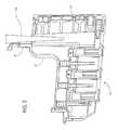
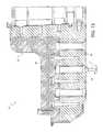
- FIG. 1is a cross-sectional side view of a cassette for preparing samples according to an embodiment of the invention
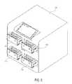
- FIG. 2is a perspective view of a cassette for preparing samples according to an embodiment of the invention
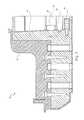
- FIG. 3is a cross-sectional side view showing a sample being placed into the cassette using a pipette, according to an embodiment of the invention
- FIG. 4is a perspective view of a magazine, in which the cassette of FIG. 1 is used, according to an embodiment of the invention
- FIG. 5is a perspective view of an instrument, in which the magazine of FIG. 4 is used, according to an embodiment of the invention
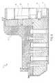
- FIG. 6is a cross-sectional side view of the cassette of FIG. 1 , showing the transfer of a PK solution into a mixing chamber, according to an embodiment of the invention
- FIG. 7is a cross-sectional side view of the cassette of FIG. 1 , showing the transfer of a lysis solution into a mixing chamber, according to an embodiment of the invention
- FIG. 8is a cross-sectional side view of the cassette of FIG. 1 , showing the transfer of a binding solution into a mixing chamber, according to an embodiment of the invention
- FIG. 9is a cross-sectional side view of the cassette of FIG. 1 , showing the transfer of metallic beads into the mixing chamber, according to an embodiment of the invention.
- FIG. 10is a cross-sectional side view of the cassette of FIG. 1 , showing metallic beads bound to a first valve, according to an embodiment of the invention
- FIG. 11is a cross-sectional side view of the cassette of FIG. 1 , showing the transfer of metallic beads from a mixing chamber to a washing chamber, according to an embodiment of the invention
- FIG. 12is a perspective end view of a valve for use in the cassette of FIG. 1 according to an embodiment of the invention.
- FIG. 13is a cross-sectional side view of the cassette of FIG. 1 , showing metallic beads bound to a second valve, according to an embodiment of the invention
- FIG. 14is a cross-sectional side view of the cassette of FIG. 1 , showing the transfer of metallic beads from a first washing chamber to a second washing chamber, according to an embodiment of the invention
- FIG. 15is a cross-sectional side view of the cassette of FIG. 1 , showing metallic beads bound to a third valve, according to an embodiment of the invention
- FIG. 16is a cross-sectional side view of the cassette of FIG. 1 , showing the transfer of metallic beads from a second washing chamber to an elution chamber, according to an embodiment of the invention
- FIG. 17is a cross-sectional side view of the cassette of FIG. 1 , showing transfer of metallic beads from an elution chamber to a second washing chamber, according to an embodiment of the invention
- FIG. 18is a cross-sectional side view of the cassette of FIG. 1 , showing removal of a prepared sample from an elution chamber, according to an embodiment of the invention
- FIG. 19is a perspective view of a magazine in which a multi-channel pipette is used to access a plurality of samples from a plurality of cassettes;
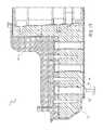
- FIG. 20is a cross-sectional perspective view of an alternative embodiment of the cassette of FIG. 1 according to an embodiment of the invention.
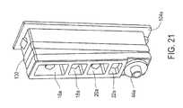
- FIG. 21is a detailed perspective view of an assembly component of the cassette of FIG. 20 according to an embodiment of the invention.
- FIG. 22is a detailed perspective view of a plunger of the cassette of FIG. 20 according to an embodiment of the invention.
- FIG. 23is a detailed perspective view of a valve of the cassette according to an embodiment of the invention.
- FIG. 24is a detailed perspective view of the valve of FIG. 23 according to an embodiment of the invention.
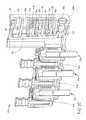
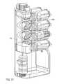
- FIG. 25is a perspective view of a cassette for preparing samples according to one embodiment of the invention.
- FIG. 26is a partial cross-sectional view of the cassette of FIG. 25 ;
- FIG. 27is a partial cross-sectional perspective view of a valve for use in the cassette of FIG. 25 ;
- FIG. 28is a partial cross-sectional side view of the valve of FIG. 25 ;
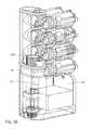
- FIG. 29is a cross-sectional perspective view of the cassette of FIG. 25 , showing the addition of a sample into a mixing chamber, according to an embodiment of the invention.
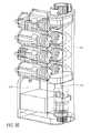
- FIG. 30is a cross-sectional perspective view of the cassette of FIG. 25 , showing the transfer of a PK solution into a mixing chamber, according to an embodiment of the invention
- FIG. 31is a cross-sectional perspective view of the cassette of FIG. 25 , showing the transfer of a lysis solution into a mixing chamber, according to an embodiment of the invention
- FIG. 32is a cross-sectional perspective view of the cassette of FIG. 25 , showing the transfer of a binding solution into a mixing chamber, according to an embodiment of the invention
- FIG. 33is a cross-sectional perspective view of the cassette of FIG. 25 , showing transfer of a sample through particles and into a waste chamber, according to an embodiment of the invention
- FIG. 34is a cross-sectional perspective view of the cassette of FIG. 25 , showing the pumping of a wash buffer into the mixing chamber, according to an embodiment of the invention
- FIG. 35is a cross-sectional perspective view of the cassette of FIG. 25 , showing the pumping of the wash buffer through the particles, according to an embodiment of the invention
- FIG. 36is a cross-sectional perspective view of the cassette of FIG. 25 , showing the pumping of a second wash buffer into the mixing chamber, according to an embodiment of the invention
- FIG. 37is a cross-sectional perspective view of the cassette of FIG. 25 , showing the pumping of the second wash buffer through the particles, according to an embodiment of the invention.
- FIG. 38is a cross-sectional perspective view of the cassette of FIG. 25 , showing the pumping of an elution buffer into the mixing chamber, according to an embodiment of the invention
- FIG. 39is a cross-sectional perspective view of the cassette of FIG. 25 , showing the pumping of the elution buffer through the particles and into the elution chamber, according to an embodiment of the invention.
- FIG. 40is a cross-sectional perspective view of the cassette of FIG. 25 , showing the removal of the sample from the elution chamber, according to an embodiment of the invention.
- FIG. 1illustrates a cassette 10 , which can be used to prepare cell samples.
- the cassette 10includes a housing 12 , a mixing chamber 14 , first, second third and fourth holding chambers 16 , 18 , 20 and 22 , first, second, third and fourth plungers 24 , 26 , 28 and 30 , first, second and third valves 32 , 34 and 36 , first and second washing chambers 38 and 40 , an elution chamber 42 , first, second, third and fourth pumps 44 , 46 , 48 and 50 , first and second lids 52 and 54 , first and second heating elements 56 and 58 and a magnet 60 .
- Each of the chambers 14 , 16 , 18 , 20 , 22 , 38 , 40 and 42 , plungers 24 , 26 , 28 and 30 , valves 32 , 34 and 36 , pumps 44 , 46 , 48 and 50 , and heating elements 56 and 58are enclosed within the housing.
- the lids 52 and 54are movably attached to the housing 12 .
- the magnet 60is removably positionable in the first valve 32 , second valve 34 and third valve 36 .
- the mixing chamber 14has a top surface 62 , a bottom surface 64 and opposing side surfaces 66 , 68 .
- the top surface 62 of the mixing chamberincludes an opening 70 therein.
- the first lid 52is configured to provide access to the opening 70 in the top surface 62 of the mixing chamber.
- the first lid 52 and the opening 70are coaxial.
- the first lid 52is shown being movably attached to the housing 12 , such that when the lid 52 is open or off, the opening 70 is accessible and if the lid 52 is closed or on, the opening 70 is not accessible.
- a thin film 74forms one wall of the mixing chamber 14 .
- the thin film 74is breakable, such that the mixing chamber 14 is accessible when the thin film 74 has been broken or ruptured.
- the first holding chamber 16 , second holding chamber 18 , third holding chamber 20 and fourth holding chamber 22are shown located next to the mixing chamber 14 and aligned vertically with one another.
- Each of the holding chambers 16 , 18 , 20 , 22has an opening 76 next to the thin film 74 of the mixing chamber 14 .
- the cassette 10further includes magnetic iron particles in the form of magnetic iron beads in the first holding chamber 16 .
- the cassette 10further includes a binding solution in the second holding chamber 18 .
- the cassette 10further includes a lysis solution in the third holding chamber 20 .
- the cassette 10further includes a proteinase K (PK) solution in the fourth holding chamber 22 .
- PKproteinase K
- the first, second, third and fourth plungers 24 , 26 , 28 and 30are located in the first, second, third and fourth holding chambers 16 , 18 , 20 and 22 , respectively.
- Each of the plungers 16 , 18 , 20 , 22includes a base 78 , a shaft 80 and a piercing element 82 .
- the shaft 80extends from the base 78 .
- the piercing element 82is at the end of the shaft 80 opposing the base 78 and is pointed.
- the piercing element 82is configured to break or rupture the thin film 74 of the mixing chamber 14 .
- the first pump 44is a bellows pump having a pumping portion and a nozzle portion.
- the nozzle portion of the first pump 44is located inside the mixing chamber 14 .
- the pumping portion of the first pump 44is located outside the mixing chamber, such that the pumping portion is actuatable.
- a heating element 56is provided at the bottom surface 64 of the mixing chamber 14 for heating the contents of the mixing chamber 14 .
- the heating element 56may be a variable heating element.
- the opposing side surface 68 of the mixing chamber 14also includes an opening 84 .
- a first valve 32is provided between the opening 84 in the side 68 of the mixing chamber 14 and the first washing chamber 38 .
- the first valve 32has a first stationary piece 86 and a second moveable piece 88 , the second piece 88 being moveable relative to the first piece 86 .
- the first stationary piece 86includes a first opening 90 and a second opening 92 and has a surface 94 .
- the second piece 88has an opening 94 therein for receiving the magnet 60 .
- the second piece 88has a surface 96 with a cavity 98 therein.
- the magnet 60is shaped to correspond to the opening 94 in the second piece 88 .
- the magnet 60is moveable in the opening 94 of the second piece 88 , and is removable from the second piece 88 .
- the cassette 10includes a washing solution in the first washing chamber 38 .
- the second pump 46is also a bellows pump, and the nozzle portion of the second pump 46 is located in the first washing chamber 38 .
- the second valve 34is provided between the first washing chamber 38 and the second washing chamber 40 .
- the second valve 34is structurally and functionally the same as the first valve 43 , and also includes a first stationary piece 86 and a second moveable piece 88 .
- the first stationary piece 86includes a first opening 90 and a second opening 92 and has a surface 94 .
- the second moveable piece 88has a surface 96 with a cavity 98 therein.
- the cassette 10includes a washing solution in the second washing chamber 40 .
- the third pump 48is also a bellows pump, and the nozzle portion of the third pump 48 is located in the second washing chamber 40 .
- the third valve 36is provided between the second washing chamber 40 and the elution chamber 42 .
- the third valve 36is structurally and functionally the same as the first valve 32 and the second valve 34 , and also includes a first stationary piece 86 and a second moveable piece 88 .
- the first stationary piece 86includes a first opening 90 and a second opening 92 and has a surface 94 .
- the second moveable piece 88has a surface 96 with a cavity 98 therein.
- the cassette 10includes a washing solution in the elution chamber 42 .
- the fourth pump 50is also a bellows pump, and the nozzle portion of the fourth pump 50 is located in the elution chamber 42 .
- a heating element 58is provided at the bottom surface of the elution chamber 42 for heating the contents of the elution chamber 42 .
- the heating element 58may be a variable heating element.
- the elution chamber 42includes an opening 100 at its top surface for accessing the contents of the elution chamber 42 .
- the second lid 54is configured to provide access to the opening 100 in the top surface of the elution chamber 42 .
- the second lid 54is coaxial with the opening 100 .
- the second lid 54is shown being movably attached to the housing 12 , such that when the lid 54 is open or off, the opening 100 is accessible and if the lid 54 is closed or on, the opening 100 is not accessible.
- the cassette 10includes a housing 12 .
- the housing 12includes a first assembly component 102 , a second assembly component 104 and a third assembly component 106 .
- the first assembly component 102includes the mixing chamber 14 , the washing chambers 38 and 40 , the elution chamber 42 and the first stationary piece 86 of each of the valves 32 , 34 and 36 .
- the first assembly component 102also includes attachment parts 108 , 110 (see FIG. 1 ) at one of its ends and an attachment piece 112 (see FIG. 1 ).
- the second assembly component 104includes the holding chambers 16 , 18 , and 22 and an opening for receiving the first pump 44 .
- the second assembly component 104also includes attachment receiving parts 114 , 116 (see FIG. 1 ).
- the third assembly component 106includes openings for receiving the second, third and fourth pumps 46 , 48 and 50 , respectively, and includes lids 52 and 54 .
- the cassette 10is assembled by inserting the attachment components 108 , 110 of the first assembly component 102 into the attachment receiving components 114 , 116 of the second assembly component 104 , respectively.
- the third assembly component 106is then secured to the first assembly component using the attachment piece 112 , thereby forming the assembled cassette 10 , as illustrated in FIG. 2 .
- the plungers 24 , 26 , 28 and 30 , pumps 44 , 46 , 48 and 50 , and the second moveable piece 88 of each of the valves 32 , 34 and 36are inserted into the cassette 10 .
- the first lid 52is removed to provide access to the opening 70 of the mixing chamber 14 .
- a sample of cellsis placed into an assembled cassette 10 using a pipette 118 .
- the cells in the sampleinclude nucleic acid.
- the pipette 118 having the sample thereinis placed in the mixing chamber 14 .
- the sampleis released from the pipette 118 .
- the cassette 10is closed by closing the first lid 52 .
- the cassette 10is then placed together with similar cassettes 10 into a magazine 120 , or rack, for containing a series of cassettes 10 .
- the magazine 120is placed into an instrument 122 .
- a protocolmay be selected for preparing the sample in the cassette 10 in the instrument 122 .
- the PK solutionis added to the sample.
- the PK solutionis added by moving the plunger 30 in the fourth holding chamber 22 .
- a forceis applied to the base 78 of the plunger 30 to move the plunger 30 .
- the piercing element 82 of the plunger 30advances toward the mixing chamber 14 , the piercing element 82 punctures and ruptures the thin film 74 .
- the break in the thin film 74provides access to the mixing chamber 14 .
- Continued motion of the plunger 30transfers the contents (e.g., PK solution) of the first holding chamber 22 into the mixing chamber 14 .
- the PK solutionis mixed with the sample by pumping the mixture with the first pump 44 .
- the PK solutiondestroys the walls of the cells of the sample, creating bulk material and nucleic acid in the bulk material.
- the lysis solutionis added to the sample.
- Plunger 28operates in the same manner as plunger 30 to transfer the lysis solution in the third holding chamber 20 into the mixing chamber 14 .
- the sampleis pumped to mix the lysis buffer with the PK solution and sample of cells.
- the lysis solutionis typically a salt or detergent.
- the lysis solutionis used to solulibize the bulk material.
- the lysis solutiontypically does not solulibize proteins.
- the heating element 56may be used to heat the lysis solution and sample.
- the heating element 56may be controlled by the instrument 122 . As described hereinabove, the temperature of the heating element 56 may be variable, and is selected to optimize the effectiveness of the lysis solution.
- the binding solutionis added to the sample, PK solution and lysis buffer solution.
- Plunger 26operates in the same manner as plunger 30 to transfer the binding solution in the second holding chamber 18 into the mixing chamber 14 .
- the solutionis pumped to mix the binding solution with the PK solution, lysis solution and sample.
- the binding solutionis typically hydrophobic and increases salt in the solution.
- the binding solutioncauses the nucleic acid to be magnetically charged.
- the magnetic beadsare added to the solution and pumped for about two minutes.
- Plunger 24operates in the same manner as plunger 30 to transfer the lysis solution in the first holding chamber 18 into the mixing chamber 14 .
- the magnetic beadsbind to the magnetically charged nucleic acid.
- the magnetic beads, together with the nucleic acid,are bound to the first valve 32 .
- the removable positionable magnet 60is placed in the first valve 32 and slid to a position in the first valve 32 to attract the magnetic beads, which are bound to the nucleic acid, from the mixing chamber 14 to the first valve 32 .
- the magnetic beads, together with the nucleic acidare then moved from the mixing chamber 14 and received in the first washing chamber 38 .
- FIG. 12is a detailed view of the valves 32 , 34 , 36 illustrating the movement of the magnetic beads from the mixing chamber 14 to the first washing chamber 38 .
- each of the valves 32 , 34 and 36include a first stationary piece 86 and a second moveable piece 88 , the second piece 88 being moveable relative to the first piece 86 .
- the magnet 60is inserted into the opening 94 of the second piece 88 .
- the magnet 60is inserted to a position corresponding to the openings 90 and 92 of the first piece 86 .
- the magnet 60attracts the magnetic beads from the mixing chamber 14 through the opening 90 in the first piece 86 and into the cavity 98 in the second piece 88 .
- the second piece 88is rotated such that the magnetic beads are sealed in the cavity 98 of the second piece 88 , between surfaces of the second piece 88 and the first piece 86 .
- the second piece 88is rotated past the surface 94 of the first piece 86 , such that the cavity 98 is accessible in the opening 92 of the first piece 86 .
- the magnet 60is then removed from the opening 94 in the second piece 88 to release the magnetic beads from the cavity 98 in the second piece 88 .
- the magnetic beads and nucleic acidare then washed with the washing solution by pumping the solution with the second pump 46 .
- the magnetic beads, together with the nucleic acid,are then bound to the second valve 34 by inserting the magnet 60 into the second valve 34 , as described above with reference to FIG. 12 .
- the magnetic beads, together with the nucleic acidare then moved from the first washing chamber 38 to the second washing chamber 40 using the second valve 34 .
- the second valve 34transfers the magnetic beads and nucleic acid from the first washing chamber 38 to the second washing chamber 40 , as described above with reference to FIG. 12 .
- the magnetic beads and nucleic acidare then washed with the washing solution a second time by pumping the solution with the third pump 48 .
- the magnetic beads, together with the nucleic acid,are then bound to the third valve 36 by positioning the magnet 60 in the third valve 36 , as described above with reference to FIG. 12 .
- the magnetic beads and nucleic acidare then moved from the second washing chamber 40 to the elution chamber 42 .
- the magnetic beads and nucleic acidare transferred from the second washing chamber 40 to the elution chamber 42 using the procedure described above with reference to FIG. 12 .
- An elution buffer solutionis then mixed with the magnetic beads and nucleic acid by pumping the solution with the fourth pump 50 .
- the heating element 58may be used to heat the elution buffer, magnetic beads and nucleic acid.
- the heating element 58may be controlled by the instrument 122 .
- the temperaturemay be variable and may be selected to optimize release of the nucleic acid from the magnetic beads.
- the magnetic beads aloneare then bound again to the third valve 36 by positioning the magnet 60 in the third valve 36 as described above with reference to FIG. 12 .
- the magnetic beads aloneare then moved from the elution chamber 42 back into the second washing chamber 40 , leaving the nucleic acid in the elution chamber 42 .
- the magnetic beadsare transferred from the elution chamber 42 to the second washing chamber 40 using the procedure described above with reference to FIG. 12 .
- the prepared sample of nucleic acidmay be accessed using a second pipette 124 .
- the second lid 54is removed to provide access to the opening 100 in the elution chamber 42 .
- the pipette 124is inserted into the opening 100 and the prepared sample of nucleic acid is withdrawn.
- a multi-channel pipette 126may be used to access a plurality of samples from a plurality of cassettes 10 .
- FIG. 20illustrates an alternative embodiment of the cassette 10 .
- the cassette 10 a illustrated in FIG. 20differs from the cassette 10 illustrated in FIG. 1 in that the assembly component 104 a includes a seal 130 , the plungers 24 a , 26 a , 28 a and 30 a each include seals 132 , 134 , 136 and 138 , respectively, and the valves 32 a , 34 a and 36 a have a different arrangement, as discussed hereinafter.
- FIG. 21illustrates the assembly component 104 a in more detail.
- the assembly component 104 aincludes a seal 130 .
- the illustrated seal 130is a double elastomer, which extends along the circumference of the assembly component 104 a.
- FIG. 22illustrates the plunger 24 a in more detail.
- the plunger 24 aincludes a seal 132 .
- the illustrated seal 132is also a double elastomer, which extends along the circumference of the plunger 24 a . It will be appreciated that each of plungers 26 a , 28 a and 30 a may also have a similar arrangement.
- FIGS. 23 and 24illustrate the valve 32 a in more detail. It will be appreciated that valves 34 a and 36 a also have a similar arrangement.
- the valve 32 aincludes a magnet 60 a , a housing 142 , and a shaft 144 .
- the housing 142includes a first opening (not shown) to receive the magnet 60 a and a second opening 148 to expose the magnet 60 a and receive the particles 146 .
- the magnet 60 ais shaped to correspond to the opening 148 and is selected to attract the particles 146 .
- the housing 142also includes a third opening (not shown) for receiving the shaft 144 .
- the shaft 144may include a keyed element 150 .
- the keyed element 150is shaped to engage the cassette 10 a .
- the shaftmay be removable or an integrated element of the valve 32 a .
- the housing 142may, alternatively, include the keyed element.
- the shaft 144is engageable with the housing 142 and magnet 60 a to rotate the housing 142 and magnet 60 a relative to the cassette 10 a to move the particles 146 from the mixing chamber 14 a to the washing chamber 38 a .
- valves 34 a and 36 aoperate in a similar manner to transfer the particles 146 from the washing chamber 38 a to the washing chamber 40 a and from the washing chamber 40 a to the elution chamber 42 a , respectively.
- a total of about 200 ⁇ L sampleis placed into the cassette.
- the sampleis mixed with a total of about 50 ⁇ L of the PK solution by pumping the mixture of the sample and PK solution for about one minute.
- a total of about 200 ⁇ L of the lysis solutionis added to the sample and PK solution, and the solutions are pumped for about one minute to mix the solutions.
- the mixtureis then heated at about 60° C. for about ten minutes, and the mixture is allowed to cool for about 5 minutes.
- the mixtureis further pumped while it cools.
- a total of about 500 ⁇ L of binding solutionis added to the mixture.
- the solutionsare pumped for about one minute.
- the magnetic beadsare added to the solution and pumped for about two minutes. The magnetic beads are transferred and washed as described above.
- a total of about 700 ⁇ L of washing solutionis provided in each of the washing chambers.
- a total of about 200 ⁇ L of elution solutionis provided in the elution chamber.
- the magnetic beadsare mixed with the elution solution by pumping the mixture for about one minute.
- the mixtureis then heated at about 90° C. for about two minutes. The process continues as previously described.
- cassette 10has been described as having a mixing chamber 14 , two washing chambers 38 and 40 and an elution chamber 42 , it is envisioned that only one washing chamber or no washing chamber may alternatively be provided.
- each valvemay include a positionable magnet, such that the magnet does not need to be removed.
- the magnet 60may be rotatable, and used to rotate the second piece of the valves. Alternatively, the magnet may only slide inside of each of the valves, and the second piece is rotated independent of the magnet.
- a cassette 10that does not use valves as described herein may be used to transfer the magnetic particles from the mixing chamber to the elution chamber.
- a slideable magnetmay be provided to transfer the magnetic particles from one chamber to the next.
- cassette 10has been described as using a PK solution, lysis solution, binding solution and magnetic beads to release the nucleic acid and magnetic beads, it is envisioned that it may be possible to practice the invention without using each of the above solutions.
- the solutionwas described as using a PK solution to break up the cells, it is envisioned that any enzyme which causes cells to break up to release nucleic acid may be used with the invention.
- the housing 12may be transparent, such that the procedure can be viewed.
- the thin film 74is a lamination.
- the lids 52 and 54may be screw-top lids. In one embodiment, the lids 52 , 54 include a hydrophobic membrane, which allows gasses to vent through the lid, but does not allow the liquids to escape the cassette 100 .
- pump 50is insertable into opening 100 .
- pump 50can also be used as a pipette to remove the sample from the cassette 10 .
- the mixing chamber 14may be provided without a puncturable thin film 74 .
- the plungers 24 , 26 , 28 and 30would not need a piercing element 82 . Instead, the plungers 24 , 26 , 28 and 30 would have a sealing element to prevent leakage of the contents of the holding chamber 16 , 18 , 20 and 22 , associated with each plunger 24 , 26 , 28 and 30 , respectively, until the plunger was moved.
- FIG. 25illustrates a cassette 200 , which can be used to prepare cell samples.
- the cassette 200includes a housing 202 , first, second, third, fourth, fifth, sixth, seventh and eighth holding chambers 204 a - h , respectively.
- Each of the holding chambers 204 a - hincludes a valve assembly 206 a - h therein.
- a locking element 207may also be provided.
- FIG. 26illustrates the cassette 200 in more detail.
- the cassette 200further includes a reaction chamber 208 , a particle chamber 210 , a waste chamber 212 , a waste overflow chamber 214 , an elution chamber 216 , a plunger 218 , and first and second lids 220 and 222 , respectively.
- the cassette 200may also include one or more heating elements (not shown).
- Each of the holding chambers 204 a - h , valve assemblies 206 a - h , reaction chamber 208 , particle chamber 210 , waster chamber 212 , waster overflow chamber 214 , and plunger 218are enclosed within the housing 202 .
- the lids 222 , 224are movably or removably attached to the housing 202 .
- the reaction chamber 208has a top surface 226 , a bottom surface 228 and opposing side surfaces 230 , 232 .
- the top surface 226 of the reaction chamber 208includes an opening 234 therein.
- the first lid 222is configured to provide access to the opening 234 in the top surface 226 of the reaction chamber 208 .
- the illustrated lid 222is a screw-top lid; however, any other lid which (removably) provides access to the opening 234 .
- the bottom surface 228 of the reaction chamber 208includes an opening 236 therein.
- the opening 236allows the reaction chamber 208 to be in fluid communication with the particle chamber 210 .
- the side surface 232includes openings 238 a - h therein.
- the openings 238 ahallow the reaction chamber 208 to be in fluid communication with the holding chambers 204 a - h , respectively.
- the cassette 200includes a binding solution in a holding chamber 204 a .
- the cassette 200further includes a lysis solution in a holding chamber 204 b .
- the cassette 200further includes a proteinase K (PK) solution in a holding chamber 204 c .
- the cassette 200further includes a washing solution in one or more of the holding chambers 204 d - e .
- the cassette 200further includes an elution solution in a holding chamber 204 f.
- the plunger 218 and the first lid 222are shown attached to one another to form an integral plunging system.
- the plunger 218is compressible to pump the contents of the reaction chamber 208 .
- a separate pumpmay also be provided to pump the contents of the reaction chamber 208 .
- the plunger 218is also moveable within the reaction chamber 208 to push the contents of the reaction chamber 208 through the particle chamber 210 .
- the holding chambers 204 a - hare formed in the housing 202 of the cassette 200 .
- Each of the holding chambers 204 a - hinclude a guide 240 a - h engageable with a corresponding slot in the valve assembly 206 .
- the holding chambers 204 a - halso include at least one opening 242 a - h , engageable with corresponding openings in the valve assembly 206 a - h .
- the housing 202also includes slots 244 a - h , engageable with corresponding guides in the valve assembly 206 a - h.
- the particle chamber 210includes a body 250 , having a first opening 252 , a second opening 254 , and a plurality of particles 256 thereon.
- the particlesmay be magnetic or nonmagnetic, depending on the application of the cassette 200 .
- the particlesmay be, for example, cellulose, plastic or iron.
- the particle chamber 210is shown aligned with the reaction chamber 208 .
- the waste chamber 212 and the elution chamber 216are integrated with one another and are rotatable relative to the housing 202 .
- the waste overflow chamber 214is positioned near the waste chamber 212 and is capable of being in fluid communication with the waste chamber 212 .
- the waste chamber 212 and elution chamber 216are alignable with the particle chamber and are capable of being in fluid communication with the particle chamber 210 .
- the waste chamber 212has a top surface 270 , a bottom surface 272 , an inner surface 274 and an outer surface 276 .
- the overflow waste chamber 214has a top surface 278 , a bottom surface 280 and opposing side surfaces 282 , 284 .
- the elution chamber 216also has a top surface 286 , a bottom surface 288 , an inner surface 290 and an outer surface 292 .
- outer surface 276 of the waste chamber 212 and the outer surface 292 of the elution chamber 216are integrated with one another. It will also be appreciated that the inner surface 274 of the waste chamber 212 is the same as the inner surface 290 of the elution chamber 216 .
- the top surface 270 of the waste chamber 212 and the top surface 286 of the elution chamber 216each have an opening 294 , 296 , respectively. These openings 294 , 296 are alignable with the opening 252 in the particle chamber 210 to provide a fluid communication route between the particle chamber 210 and the waste chamber 212 and the elution chamber 216 .
- the outer surface 276 of the waste chamber 212includes an opening 298 therein.
- One of the side surfaces 282 , 284 of the overflow waste chamber 214includes an opening 300 therein.
- the opening 298 and opening 300are alignable, such that fluid flowing into the waste chamber 212 can flow from the waste chamber 212 and into the overflow waste chamber 214 .
- the bottom surface 288 of the elution chamber 216includes an opening 302 therein.
- the second lid 224is configured to provide access to the opening 302 in the bottom surface 288 of the elution chamber 216 .
- the illustrated lid 224is a screw-top lid; however, any other lid which (removably) provides access to the opening 302 .
- FIGS. 27 and 28illustrate the valve assembly 206 in more detail.
- Valve assembly 206includes a housing 310 .
- the housing 310includes a chamber 312 therein, a slot 314 , and projections 316 extending therefrom.
- the chamber 312includes a pump 318 therein.
- a lid 320is provided at an end of the housing to seal the chamber 310 .
- the lidincludes first and second openings 322 , 324 , extending therethrough and providing fluid communication with the chamber 312 .
- the contents of the chamber 312are sealed within the valve assembly; however, when the openings 322 , 324 are aligned with openings 238 a - h , the contents of the chamber 312 are releasable from the chamber 312 .
- the slot 314is used to guide the openings 322 , 324 to the location where the openings 322 , 324 are aligned with the openings 238 a - h .
- the pump 318is used to transfer the contents from the chamber 312 and into the reaction chamber 214 through the openings 322 , 324 .
- the cassette 200is assembled by inserting the valve assemblies 206 a - h into the holding chambers 204 a - h of the housing.
- the locking element 207may be connected to the housing to secure valve assemblies 206 a - h in the holding chambers 204 a - h .
- the waste chamber and elution chamber 216 assemblyis inserted into the housing 202 and the lid 224 is secured to the housing 202 .
- the plunger 218is also inserted into the reaction chamber 208 and the lid 222 is secured to the housing.
- the first lid 222is removed to provide access to the opening 234 of the reaction chamber 208 .
- a sample of cells 350is placed into the cassette 200 using a pipette 352 .
- the cells in the sampleinclude nucleic acid.
- the pipette 352 having the sample thereinis placed in the reaction chamber 208 .
- the sampleis released from the pipette 352 .
- the PK solutionis added to the sample.
- the PK solutionis added by rotating the valve assembly 206 c relative to the housing 202 .
- At least one of the openings 322 , 324 of the valve assembly 206 cis aligned with the opening 242 c in the holding chamber 204 c to release the PK solution from the holding chamber 204 c and into the reaction chamber 208 through the opening 238 c in the housing 202 .
- the PK Solutionis mixed with the sample by pumping the mixture with the plunger 218 .
- the PK solutiondestroys the wall so the cells of the sample, creating bulk material and nucleic acid in the bulk material.
- the lysis solutionis added to the sample.
- the valve assembly 206 boperates in the same manner as valve assembly 206 c to transfer the lysis solution in the holding chamber 204 b into the reaction chamber 208 .
- the sampleis typically pumped to mix the lysis solution with the mixed PK solution and sample.
- the lysis solutionis typically a salt or detergent, and is used to solulibize the bulk material, as discussed hereinabove.
- Valve assembly 206 aoperates in the same manner as valve assembly 206 c to transfer the binding solution in the holding chamber 204 a into the reaction chamber 208 .
- the solutionis pumped to mix the binding solution with the PK solution, lysis solution and sample.
- the binding solutionis typically hydrophobic and increases sale in the solution.
- the solutionis pumped through the particles in the particle chamber 210 .
- the nucleic acidbinds to the particles in the particle chamber, while the remaining solution flows into the waste chamber 212 , and, if needed, the waste overflow chamber 214 .
- the opening 298 in the waste chamber 212is aligned with the opening 300 in the waste overflow chamber 214 , the solution can flow into the waste overflow chamber 214 from the waste chamber 212 .
- the washing solutionis added to the reaction chamber 208 by operating the valve assembly 206 d in the same manner as valve assembly 206 c to transfer the washing solution from the holding chamber 204 d into the reaction chamber 208 .
- the first washing solutionis pumped through the particle chamber 210 and into the waste chamber 212 , and, if needed, the waste overflow chamber 214 .
- a second washing solutionis added to the reaction chamber 208 by operating the valve assembly 206 e in the same manner as valve assembly 206 c to transfer the washing solution from the holding chamber 204 e into the reaction chamber 208 .
- the second washing solutionis pumped through the particle chamber 210 and into the waste chamber 212 , and, if needed, the waste overflow chamber 214 .
- an elution solutionis added to the reaction chamber 208 by operating the valve assembly 206 f in the same manner as valve assembly 206 c to transfer the elution solution from the holding chamber 204 f into the reaction chamber 208 .
- the waste chamber and elution chamber assemblyis rotated to align the opening 296 of the elution chamber 216 with the opening 252 of the particle chamber 210 such that the elution solution is transferable into the elution chamber 216 . It will be appreciated that the opening 296 can be aligned with the opening 252 before or after the elution solution is added to the reaction chamber 208 .
- the elution solutionis pumped through the particle chamber 210 to elute the bound nucleic acid.
- the nucleic acid and elution solutionflow into the elution chamber 216 .
- the prepared sample of nucleic acidmay be accessed using a pipette 354 .
- the second lid 224is removed to provide access to the opening 302 in the elution chamber 216 .
- the pipette 354is inserted into the opening 302 and the prepared sample of nucleic acid is withdrawn.
- the cassette 200can be placed with similar cassettes into a magazine or rack for containing a series of cassettes.
- the magazine or rackcan be placed into an instrument, and a protocol may be selected for preparing the sample in the cassette 200 in the instrument.
- Cassette 200may include one or more heating elements as described hereinabove with respect to cassette 100 .
- the cassettes 100 , 200may be disposable.
- cassettes 100 , 200have been described with respect to breaking cells to extract nucleic acid, the cassettes 100 , 200 can be used to break cells to extract other cell components, such as, for example, protein. Also, although a lysis solution has been described as being used to break up cells, it will be appreciated that any substance that can break up cells, such as, for example, reagents, enzymes, catatropic salts, other lysis solutions and the like.
- the cassettes described hereinare advantageous because it is closed. There is no contamination of the sample during the process. In addition, a fewer number of samples, including as few as one sample, may be prepared.
Landscapes
- Chemical & Material Sciences (AREA)
- Health & Medical Sciences (AREA)
- Chemical Kinetics & Catalysis (AREA)
- Life Sciences & Earth Sciences (AREA)
- Engineering & Computer Science (AREA)
- Analytical Chemistry (AREA)
- Organic Chemistry (AREA)
- General Health & Medical Sciences (AREA)
- Wood Science & Technology (AREA)
- Zoology (AREA)
- Bioinformatics & Cheminformatics (AREA)
- Genetics & Genomics (AREA)
- Biotechnology (AREA)
- Biochemistry (AREA)
- Biomedical Technology (AREA)
- General Engineering & Computer Science (AREA)
- Clinical Laboratory Science (AREA)
- Physics & Mathematics (AREA)
- Microbiology (AREA)
- Immunology (AREA)
- Molecular Biology (AREA)
- Biophysics (AREA)
- Proteomics, Peptides & Aminoacids (AREA)
- Hematology (AREA)
- General Physics & Mathematics (AREA)
- Pathology (AREA)
- Plant Pathology (AREA)
- Crystallography & Structural Chemistry (AREA)
- Medicinal Chemistry (AREA)
- Sustainable Development (AREA)
- Apparatus Associated With Microorganisms And Enzymes (AREA)
- Automatic Analysis And Handling Materials Therefor (AREA)
Abstract
Description
Claims (20)
Priority Applications (11)
| Application Number | Priority Date | Filing Date | Title |
|---|---|---|---|
| US12/789,831US8124024B2 (en) | 2005-10-19 | 2010-05-28 | Cassette for sample preparation |
| US13/033,129US8372340B2 (en) | 2005-10-19 | 2011-02-23 | Apparatus and methods for integrated sample preparation, reaction and detection |
| US13/357,947US8476078B2 (en) | 2005-10-19 | 2012-01-25 | Cassette for sample preparation |
| US13/759,557US9074250B2 (en) | 2005-10-19 | 2013-02-05 | Apparatus and methods for integrated sample preparation, reaction and detection |
| US13/910,953US9017617B2 (en) | 2005-10-19 | 2013-06-05 | Cassette for sample preparation |
| US14/666,573US9624531B2 (en) | 2005-10-19 | 2015-03-24 | Cassette for sample preparation |
| US14/723,586US9539577B2 (en) | 2005-10-19 | 2015-05-28 | Apparatus and methods for integrated sample preparation, reaction and detection |
| US15/366,186US10040071B2 (en) | 2005-10-19 | 2016-12-01 | Apparatus and methods for integrated sample preparation, reaction and detection |
| US15/456,029US9828598B2 (en) | 2005-10-19 | 2017-03-10 | Cassette for sample preparation |
| US15/792,989US10472622B2 (en) | 2005-10-19 | 2017-10-25 | Cassette for sample preparation |
| US16/032,183US10646875B2 (en) | 2005-10-19 | 2018-07-11 | Apparatus and methods for integrated sample preparation, reaction and detection |
Applications Claiming Priority (5)
| Application Number | Priority Date | Filing Date | Title |
|---|---|---|---|
| US72856905P | 2005-10-19 | 2005-10-19 | |
| US75362205P | 2005-12-22 | 2005-12-22 | |
| US75361805P | 2005-12-22 | 2005-12-22 | |
| US11/582,651US7727473B2 (en) | 2005-10-19 | 2006-10-17 | Cassette for sample preparation |
| US12/789,831US8124024B2 (en) | 2005-10-19 | 2010-05-28 | Cassette for sample preparation |
Related Parent Applications (2)
| Application Number | Title | Priority Date | Filing Date |
|---|---|---|---|
| US11/582,651ContinuationUS7727473B2 (en) | 2005-10-19 | 2006-10-17 | Cassette for sample preparation |
| US13/033,129ContinuationUS8372340B2 (en) | 2005-10-19 | 2011-02-23 | Apparatus and methods for integrated sample preparation, reaction and detection |
Related Child Applications (3)
| Application Number | Title | Priority Date | Filing Date |
|---|---|---|---|
| US12/821,446Continuation-In-PartUS7910062B2 (en) | 2005-10-19 | 2010-06-23 | Instrument for cassette for sample preparation |
| US13/033,129Continuation-In-PartUS8372340B2 (en) | 2005-10-19 | 2011-02-23 | Apparatus and methods for integrated sample preparation, reaction and detection |
| US13/357,947ContinuationUS8476078B2 (en) | 2005-10-19 | 2012-01-25 | Cassette for sample preparation |
Publications (2)
| Publication Number | Publication Date |
|---|---|
| US20100239471A1 US20100239471A1 (en) | 2010-09-23 |
| US8124024B2true US8124024B2 (en) | 2012-02-28 |
Family
ID=37948596
Family Applications (7)
| Application Number | Title | Priority Date | Filing Date |
|---|---|---|---|
| US11/582,651Active2029-02-13US7727473B2 (en) | 2005-10-19 | 2006-10-17 | Cassette for sample preparation |
| US12/789,831ActiveUS8124024B2 (en) | 2005-10-19 | 2010-05-28 | Cassette for sample preparation |
| US13/357,947Expired - Fee RelatedUS8476078B2 (en) | 2005-10-19 | 2012-01-25 | Cassette for sample preparation |
| US13/910,953Active2027-01-08US9017617B2 (en) | 2005-10-19 | 2013-06-05 | Cassette for sample preparation |
| US14/666,573Expired - Fee RelatedUS9624531B2 (en) | 2005-10-19 | 2015-03-24 | Cassette for sample preparation |
| US15/456,029ActiveUS9828598B2 (en) | 2005-10-19 | 2017-03-10 | Cassette for sample preparation |
| US15/792,989Active2027-05-17US10472622B2 (en) | 2005-10-19 | 2017-10-25 | Cassette for sample preparation |
Family Applications Before (1)
| Application Number | Title | Priority Date | Filing Date |
|---|---|---|---|
| US11/582,651Active2029-02-13US7727473B2 (en) | 2005-10-19 | 2006-10-17 | Cassette for sample preparation |
Family Applications After (5)
| Application Number | Title | Priority Date | Filing Date |
|---|---|---|---|
| US13/357,947Expired - Fee RelatedUS8476078B2 (en) | 2005-10-19 | 2012-01-25 | Cassette for sample preparation |
| US13/910,953Active2027-01-08US9017617B2 (en) | 2005-10-19 | 2013-06-05 | Cassette for sample preparation |
| US14/666,573Expired - Fee RelatedUS9624531B2 (en) | 2005-10-19 | 2015-03-24 | Cassette for sample preparation |
| US15/456,029ActiveUS9828598B2 (en) | 2005-10-19 | 2017-03-10 | Cassette for sample preparation |
| US15/792,989Active2027-05-17US10472622B2 (en) | 2005-10-19 | 2017-10-25 | Cassette for sample preparation |
Country Status (8)
| Country | Link |
|---|---|
| US (7) | US7727473B2 (en) |
| EP (2) | EP3216855B1 (en) |
| JP (1) | JP5298271B2 (en) |
| KR (2) | KR101349893B1 (en) |
| CN (2) | CN101379180B (en) |
| AU (1) | AU2006304623B2 (en) |
| CA (2) | CA2912883C (en) |
| WO (1) | WO2007047814A2 (en) |
Cited By (14)
| Publication number | Priority date | Publication date | Assignee | Title |
|---|---|---|---|---|
| US8829473B1 (en) | 2013-03-13 | 2014-09-09 | GeneWeave Biosciences, Inc. | Systems and methods for detection of cells using engineered transduction particles |
| US9017617B2 (en) | 2005-10-19 | 2015-04-28 | Luminex Corporation | Cassette for sample preparation |
| US9074250B2 (en) | 2005-10-19 | 2015-07-07 | Luminex Corporation | Apparatus and methods for integrated sample preparation, reaction and detection |
| US9273344B2 (en) | 2006-12-27 | 2016-03-01 | Luminex Corporation | Instrument for cassette for sample preparation |
| US9388453B2 (en) | 2013-03-13 | 2016-07-12 | GeneWeave Biosciences, Inc. | Non-replicative transduction particles and transduction particle-based reporter systems |
| US9540675B2 (en) | 2013-10-29 | 2017-01-10 | GeneWeave Biosciences, Inc. | Reagent cartridge and methods for detection of cells |
| US9931636B2 (en) | 2010-02-23 | 2018-04-03 | Luminex Corporation | Apparatus and method for integrated sample preparation, reaction and detection |
| US10022720B2 (en) | 2015-06-12 | 2018-07-17 | Cytochip Inc. | Fluidic units and cartridges for multi-analyte analysis |
| US10040062B2 (en)* | 2014-01-14 | 2018-08-07 | Wisconsin Alumni Research Foundation | Device and method for transferring a target between locations |
| US10077999B2 (en) | 2015-07-14 | 2018-09-18 | Cytochip Inc. | Volume sensing in fluidic cartridge |
| US10351893B2 (en) | 2015-10-05 | 2019-07-16 | GeneWeave Biosciences, Inc. | Reagent cartridge for detection of cells |
| US10634602B2 (en) | 2015-06-12 | 2020-04-28 | Cytochip Inc. | Fluidic cartridge for cytometry and additional analysis |
| US11077444B2 (en) | 2017-05-23 | 2021-08-03 | Roche Molecular Systems, Inc. | Packaging for a molecular diagnostic cartridge |
| US11491487B2 (en) | 2017-10-23 | 2022-11-08 | Cytochip Inc. | Devices and methods for measuring analytes and target particles |
Families Citing this family (42)
| Publication number | Priority date | Publication date | Assignee | Title |
|---|---|---|---|---|
| US6218383B1 (en) | 1998-08-07 | 2001-04-17 | Targacept, Inc. | Pharmaceutical compositions for the prevention and treatment of central nervous system disorders |
| EP3192876A1 (en) | 2007-10-10 | 2017-07-19 | Pocared Diagnostics Ltd. | System for conducting the identification of bacteria in urine |
| CN104251911B (en) | 2008-02-05 | 2017-05-31 | 普凯尔德诊断技术有限公司 | System for identifying bacterium in biological sample |
| CA2772020A1 (en)* | 2009-08-31 | 2011-03-03 | Mbio Diagnostics, Inc. | Integrated sample preparation and analyte detection |
| US10288632B2 (en) | 2009-09-21 | 2019-05-14 | Pocared Diagnostics Ltd. | System for conducting the identification of bacteria in biological samples |
| TWI414771B (en)* | 2009-11-03 | 2013-11-11 | Apex Biotechnology Corp | Reaction cassette, assay device, and measuring method |
| CN103675303B (en)* | 2010-07-23 | 2016-02-03 | 贝克曼考尔特公司 | Sensing system |
| SI3270141T1 (en) | 2011-03-08 | 2021-03-31 | Universite Laval | Fluidic centripetal device |
| CN102331412B (en)* | 2011-10-08 | 2013-12-11 | 左峰 | Multifunctional analyzer device |
| KR101481054B1 (en) | 2011-11-15 | 2015-01-14 | 한국기계연구원 | A device for automatically analyzing nucleic acid |
| ES2427548B1 (en)* | 2012-02-02 | 2014-10-01 | Fundación Gaiker | Analysis sample preparation device, support, analysis sample preparation system, sample preparation method and sample analysis method |
| CZ304743B6 (en)* | 2013-01-18 | 2014-09-17 | Wolf & Danniel S.R.O. | Means for isolation of nucleic acids and method carried out by means of the means |
| AU2013202805B2 (en)* | 2013-03-14 | 2015-07-16 | Gen-Probe Incorporated | System and method for extending the capabilities of a diagnostic analyzer |
| US10767146B2 (en) | 2013-10-25 | 2020-09-08 | Becton, Dickinson And Company | Blood culture bottles with mechanisms for controlled release of substances into culture media |
| US9827567B2 (en) | 2014-04-22 | 2017-11-28 | Nanosphere, Inc. | Diagnostic cartridges having flexible seals |
| CN106268407A (en)* | 2015-06-02 | 2017-01-04 | 奥健生物科技(广州)有限公司 | Material separate storage type mixing pump |
| US11260386B2 (en)* | 2015-06-05 | 2022-03-01 | The Emerther Company | Component of a device, a device, and a method for purifying and testing biomolecules from biological samples |
| CN105372102B (en)* | 2015-07-14 | 2017-11-28 | 黄桂晓 | A kind of medical test punctures specimen collection fixing device |
| USD799715S1 (en) | 2015-10-23 | 2017-10-10 | Gene POC, Inc. | Fluidic centripetal device |
| CN105334072B (en)* | 2015-12-08 | 2019-04-05 | 青岛海盈智高新技术有限公司 | A kind of sealed fecal sample sampling container and sampling method |
| US10907147B2 (en)* | 2016-03-15 | 2021-02-02 | Abbott Molecular Inc. | Sample processing devices, systems and methods |
| US20170299483A1 (en)* | 2016-04-18 | 2017-10-19 | California Institute Of Technology | Devices and methods for preparing biological samples |
| CN106086003A (en)* | 2016-06-17 | 2016-11-09 | 易初丽 | A kind of nucleic acid purification system |
| US11364495B2 (en) | 2016-12-01 | 2022-06-21 | Novel Microdevices, Llc | Automated point-of-care devices for complex sample processing and methods of use thereof |
| CN106979884B (en)* | 2017-04-20 | 2020-09-04 | 汪小明 | Urine analyzer convenient to shake reagent evenly |
| CN110408533B (en)* | 2018-04-28 | 2024-08-09 | 康码(上海)生物科技有限公司 | Array-type integrated biological automatic reaction chip and its use method |
| WO2020014296A1 (en) | 2018-07-12 | 2020-01-16 | Luminex Corporation | Systems and methods for performing variable sample preparation and analysis processes |
| CN108795699B (en)* | 2018-07-19 | 2023-12-26 | 嘉兴医脉赛科技有限公司 | Enclosed magnetic bead purifying instrument |
| CN108865658B (en)* | 2018-08-27 | 2023-12-08 | 苏州绘真医学检验有限公司 | Tubular plasma free nucleic acid extraction method and system |
| CN110455590B (en)* | 2019-08-20 | 2021-08-31 | 南京市第一医院 | Obstetrical urine detection instrument |
| CN111189673B (en)* | 2020-03-04 | 2021-08-31 | 河海大学 | A water-sand interface water sampling system and its sampling method |
| WO2022125069A1 (en)* | 2020-12-08 | 2022-06-16 | Hp Health Solutions Inc. | Sample preparation mixers |
| CN112760193A (en)* | 2020-12-30 | 2021-05-07 | 北京航空航天大学 | Nucleic acid extraction/detection device and method |
| CN113069972B (en)* | 2021-04-26 | 2023-04-25 | 河南省儿童医院郑州儿童医院 | A blood collection anticoagulation device |
| CN113176790B (en)* | 2021-05-11 | 2022-02-15 | 北京中科生仪科技有限公司 | Liquid path control device based on PCR |
| TWI815219B (en)* | 2021-11-19 | 2023-09-11 | 台達電子工業股份有限公司 | Nucleic acid processing device and sample pre-processing module thereof |
| CN114383238B (en)* | 2022-01-18 | 2023-04-07 | 广东工业大学 | Epidemic prevention growable public negative pressure room, group and isolation prevention and control method |
| CN114570248B (en)* | 2022-03-14 | 2023-02-24 | 河南省肿瘤医院 | A detection system for intravenous drug configuration based on deep learning |
| CN114558632B (en)* | 2022-04-26 | 2022-09-27 | 广州国家实验室 | Liquid transfer device, multi-channel liquid transfer device and method |
| KR102844665B1 (en)* | 2022-09-28 | 2025-08-11 | (주)마이크로디지탈 | Apparatus for pre-processing collected sample and pre-processing method |
| WO2024074712A1 (en)* | 2022-10-06 | 2024-04-11 | Abbott Rapid Diagnostics International Unlimited Company | Device and method for analyte isolation |
| KR102806525B1 (en)* | 2022-11-11 | 2025-05-16 | (주)마이크로디지탈 | Apparatus for pre-processing complex sample and pre-processing method |
Citations (76)
| Publication number | Priority date | Publication date | Assignee | Title |
|---|---|---|---|---|
| US5139745A (en)* | 1990-03-30 | 1992-08-18 | Block Medical, Inc. | Luminometer |
| US5188455A (en) | 1990-11-13 | 1993-02-23 | The Pennsylvania Research Corporation | Apparatus for remote mixing of fluids |
| US5242837A (en) | 1990-12-24 | 1993-09-07 | Slovacek Rudolf E | Method for the rapid detection of analytes involving specific binding reactions and the use of light attenuating magnetic particles |
| US5242660A (en) | 1992-02-28 | 1993-09-07 | Paul Hsei | Sample preparation device |
| US5415839A (en) | 1993-10-21 | 1995-05-16 | Abbott Laboratories | Apparatus and method for amplifying and detecting target nucleic acids |
| US5475610A (en) | 1990-11-29 | 1995-12-12 | The Perkin-Elmer Corporation | Thermal cycler for automatic performance of the polymerase chain reaction with close temperature control |
| US5494646A (en) | 1993-04-14 | 1996-02-27 | Seymour; Eugene H. | Sampling device and sample adequacy system |
| US5508197A (en) | 1994-07-25 | 1996-04-16 | The Regents, University Of California | High-speed thermal cycling system and method of use |
| US5580523A (en) | 1994-04-01 | 1996-12-03 | Bard; Allen J. | Integrated chemical synthesizers |
| US5589136A (en) | 1995-06-20 | 1996-12-31 | Regents Of The University Of California | Silicon-based sleeve devices for chemical reactions |
| US5627041A (en) | 1994-09-02 | 1997-05-06 | Biometric Imaging, Inc. | Disposable cartridge for an assay of a biological sample |
| US5639423A (en) | 1992-08-31 | 1997-06-17 | The Regents Of The University Of Calfornia | Microfabricated reactor |
| US5645801A (en) | 1993-10-21 | 1997-07-08 | Abbott Laboratories | Device and method for amplifying and detecting target nucleic acids |
| US5665975A (en) | 1993-11-02 | 1997-09-09 | Affymax Technologies N.V. | Optical detectior including an optical alignment block and method |
| US5746978A (en) | 1994-06-15 | 1998-05-05 | Boehringer Mannheim Gmbh | Device for treating nucleic acids from a sample |
| US5759784A (en) | 1994-05-06 | 1998-06-02 | Pharmacia Biotech Ab | Method of nucleic acid transfer |
| US5827480A (en) | 1993-07-28 | 1998-10-27 | The Perkin-Elmer Corporation | Nucleic acid amplification reaction apparatus |
| US5861124A (en) | 1993-07-15 | 1999-01-19 | Hamamatsu Photonics Kk | Method and apparatus for detecting denaturation of nucleic acid |
| US5882903A (en) | 1996-11-01 | 1999-03-16 | Sarnoff Corporation | Assay system and method for conducting assays |
| US5904899A (en) | 1997-05-15 | 1999-05-18 | Tosoh Corporation | Assaying apparatus and a vessel holder device in use with the assaying apparatus |
| US5989499A (en) | 1997-05-02 | 1999-11-23 | Biomerieux, Inc. | Dual chamber disposable reaction vessel for amplification reactions |
| US6050719A (en) | 1998-01-30 | 2000-04-18 | Affymetrix, Inc. | Rotational mixing method using a cartridge having a narrow interior |
| US6071748A (en) | 1997-07-16 | 2000-06-06 | Ljl Biosystems, Inc. | Light detection device |
| US6281008B1 (en) | 1998-02-02 | 2001-08-28 | Toyo Boseki Kabushiki Kaisha | Nucleic acid extraction apparatus |
| US20010036672A1 (en)* | 1995-06-29 | 2001-11-01 | Anderson Rolfe C. | Integrated nucleic acid diagnostic device |
| US6358387B1 (en) | 2000-03-27 | 2002-03-19 | Caliper Technologies Corporation | Ultra high throughput microfluidic analytical systems and methods |
| US6429007B1 (en) | 1997-05-02 | 2002-08-06 | BIOMéRIEUX, INC. | Nucleic acid amplification reaction station for disposable test devices |
| US6451258B1 (en) | 1997-05-28 | 2002-09-17 | Alphahelix Ab | Reaction vessel, cassette and system for performing biochemical reactions |
| US6517778B1 (en) | 1994-06-06 | 2003-02-11 | Idexx Laboratories | Immunoassays in capillary tubes |
| US6520197B2 (en) | 2000-06-02 | 2003-02-18 | The Regents Of The University Of California | Continuous laminar fluid mixing in micro-electromechanical systems |
| US6565815B1 (en) | 1997-02-28 | 2003-05-20 | Cepheid | Heat exchanging, optically interrogated chemical reaction assembly |
| US6576459B2 (en) | 2001-03-23 | 2003-06-10 | The Regents Of The University Of California | Sample preparation and detection device for infectious agents |
| US6597450B1 (en) | 1997-09-15 | 2003-07-22 | Becton, Dickinson And Company | Automated Optical Reader for Nucleic Acid Assays |
| WO2004005553A1 (en) | 2002-07-10 | 2004-01-15 | Massachusetts Institute Of Technology | Apparatus and method for isolating a nucleic acid from a sample |
| US6699713B2 (en) | 2000-01-04 | 2004-03-02 | The Regents Of The University Of California | Polymerase chain reaction system |
| US6783934B1 (en) | 2000-05-01 | 2004-08-31 | Cepheid, Inc. | Methods for quantitative analysis of nucleic acid amplification reaction |
| WO2004080597A2 (en) | 2003-02-05 | 2004-09-23 | Iquum, Inc. | Sample processing tubule |
| US20040200909A1 (en)* | 1999-05-28 | 2004-10-14 | Cepheid | Apparatus and method for cell disruption |
| US20040209266A1 (en)* | 2001-04-30 | 2004-10-21 | Squirrell David James | Reagent delivery system |
| US20040222395A1 (en)* | 2003-04-21 | 2004-11-11 | Yee Young Joo | Valve apparatus for controlling mass flow, manufacturing method thereof and heat exchanger using the same |
| US6818185B1 (en) | 1999-05-28 | 2004-11-16 | Cepheid | Cartridge for conducting a chemical reaction |
| US6838680B2 (en) | 1999-05-12 | 2005-01-04 | Aclara Biosciences, Inc. | Multiplexed fluorescent detection in microfluidic devices |
| US6852284B1 (en) | 1998-05-18 | 2005-02-08 | University Of Washington | Liquid analysis cartridge |
| US6875602B2 (en) | 2002-09-24 | 2005-04-05 | The United States Of America As Represented By The Secretary Of The Army | Portable thermocycler |
| US6890742B2 (en) | 1998-05-01 | 2005-05-10 | Gen-Probe Incorporated | Automated process for isolating and amplifying a target nucleic acid sequence |
| US6893879B2 (en) | 1997-08-13 | 2005-05-17 | Cepheid | Method for separating analyte from a sample |
| US6955589B2 (en) | 2001-05-22 | 2005-10-18 | Qed Technologies, Inc. | Delivery system for magnetorheological fluid |
| US20050244837A1 (en) | 2004-04-28 | 2005-11-03 | Cepheid | Method and device for sample preparation control |
| US20060194264A1 (en) | 1996-12-20 | 2006-08-31 | Sheppard Norman F Jr | Affinity based system for detecting particulates in a fluid |
| US20060205085A1 (en) | 2003-07-31 | 2006-09-14 | Kalyan Handique | Processing particle-containing samples |
| US7108472B2 (en) | 2000-07-10 | 2006-09-19 | Affymetrix, Inc. | Cartridge loader and methods |
| US20060246490A1 (en) | 1995-06-29 | 2006-11-02 | Affymetrix, Inc. | Miniaturized genetic analysis systems and methods |
| US20060257991A1 (en) | 2004-02-27 | 2006-11-16 | Mcdevitt John T | Integration of fluids and reagents into self-contained cartridges containing particle-based sensor elements and membrane-based sensor elements |
| US7171863B2 (en) | 2001-09-12 | 2007-02-06 | Olympus Corporation | Transfer unit and automatic analyzing apparatus having such transfer unit |
| US20070054349A1 (en) | 2003-09-24 | 2007-03-08 | Lux Biotechnology Limited | Biochip |
| US20070054293A1 (en) | 2005-08-30 | 2007-03-08 | California Institute Of Technology | Microfluidic chaotic mixing systems and methods |
| US20070077646A1 (en) | 2005-10-04 | 2007-04-05 | Canon Kabushiki Kaisha | Apparatus for performing biochemical processing using a container with a plurality of wells and the container for the apparatus |
| US20070087431A1 (en) | 2005-10-19 | 2007-04-19 | Jesus Ching | Cassette for sample preparation |
| US20070099289A1 (en) | 2003-06-13 | 2007-05-03 | The General Hospital Corporation | Device and method for contacting picoliter volumes of fluid |
| US7284900B2 (en) | 2001-10-19 | 2007-10-23 | Monogen, Inc. | Apparatus and method for mixing specimens in vials |
| US20070248958A1 (en) | 2004-09-15 | 2007-10-25 | Microchip Biotechnologies, Inc. | Microfluidic devices |
| US7294466B2 (en) | 2004-05-07 | 2007-11-13 | Cepheid | Multiplexed detection of biological agents |
| US7301628B2 (en) | 2000-10-30 | 2007-11-27 | Sru Biosystems, Inc. | Method and apparatus for detecting biomolecular interactions |
| US20080003649A1 (en) | 2006-05-17 | 2008-01-03 | California Institute Of Technology | Thermal cycling system |
| US7341691B2 (en) | 2001-09-13 | 2008-03-11 | Olympus Corporation | Automatic analyzing apparatus |
| US7358078B2 (en) | 2003-05-02 | 2008-04-15 | Dr. Chip Biotechnology Incorporation | Auto microfluidic hybridization chip platform |
| US20080153096A1 (en) | 2006-11-02 | 2008-06-26 | Vectrant Technologies Inc. | Cartridge for conducting diagnostic assays |
| US20080159915A1 (en) | 2006-12-27 | 2008-07-03 | Steve Jia Chang Yu | Instrument for cassette for sample preparation |
| US20080280285A1 (en) | 2005-05-11 | 2008-11-13 | Chen Zongyuan G | Systems and Methods For Testing using Microfluidic Chips |
| US20090023201A1 (en) | 2007-03-23 | 2009-01-22 | Sadato Hongo | Nucleic acid detecting cassette and nucleic acid detecting apparatus |
| US20090155838A1 (en) | 2007-11-28 | 2009-06-18 | Smart Tube, Inc. | Devices, systems and methods for the collection, stimulation, stabilization, and analysis of a biological sample |
| US20090186357A1 (en) | 2007-12-10 | 2009-07-23 | The Trustees Of The University Of Pennsylvania | Integrated PCR Reactor for Cell Lysis, Nucleic Acid Isolation and Purification, and Nucleic Acid Amplication Related Applications |
| US20090186344A1 (en) | 2008-01-23 | 2009-07-23 | Caliper Life Sciences, Inc. | Devices and methods for detecting and quantitating nucleic acids using size separation of amplicons |
| US7584019B2 (en) | 2003-12-15 | 2009-09-01 | Dako Denmark A/S | Systems and methods for the automated pre-treatment and processing of biological samples |
| US20090269841A1 (en) | 2006-05-22 | 2009-10-29 | Biovest International, Inc. | Method and system for the production of cells and cell products and applications thereof |
| US20090291507A1 (en) | 2007-02-15 | 2009-11-26 | Osmetech Technology Inc. | Fluidics devices |
Family Cites Families (155)
| Publication number | Priority date | Publication date | Assignee | Title |
|---|---|---|---|---|
| US2940448A (en) | 1957-04-29 | 1960-06-14 | Jr Norman B Furlong | Disposable blood-gas analyzer |
| SE327840B (en) | 1968-01-25 | 1970-08-31 | Atuokemi Ab | |
| US3802782A (en) | 1970-08-19 | 1974-04-09 | Rohe Scientific Corp | Chemical analyzer performing sequential analysis of samples |
| US4004150A (en) | 1975-05-01 | 1977-01-18 | Samuel Natelson | Analytical multiple component readout system |
| US4201578A (en) | 1977-11-03 | 1980-05-06 | Eastman Kodak Company | Blocked competing developers for color transfer |
| US4448534A (en) | 1978-03-30 | 1984-05-15 | American Hospital Corporation | Antibiotic susceptibility testing |
| FI63296C (en) | 1980-07-11 | 1983-05-10 | Eflab Oy | fotometer |
| JPS5848836A (en) | 1981-09-18 | 1983-03-22 | Toa Medical Electronics Co Ltd | Optical type automatic analyzing and measuring device |
| US4626684A (en) | 1983-07-13 | 1986-12-02 | Landa Isaac J | Rapid and automatic fluorescence immunoassay analyzer for multiple micro-samples |
| US5500188A (en) | 1984-03-01 | 1996-03-19 | Molecular Devices Corporation | Device for photoresponsive detection and discrimination |
| DE3441179C2 (en) | 1984-11-10 | 1987-02-26 | Dynatech Deutschland GmbH, 7306 Denkendorf | Temperature control device for micro-cuvette arrangements, especially for microtitration plates |
| US5656493A (en) | 1985-03-28 | 1997-08-12 | The Perkin-Elmer Corporation | System for automated performance of the polymerase chain reaction |
| US5333675C1 (en) | 1986-02-25 | 2001-05-01 | Perkin Elmer Corp | Apparatus and method for performing automated amplification of nucleic acid sequences and assays using heating and cooling steps |
| GB8607975D0 (en) | 1986-04-01 | 1986-05-08 | Fisons Plc | Devices |
| US5229297A (en) | 1989-02-03 | 1993-07-20 | Eastman Kodak Company | Containment cuvette for PCR and method of use |
| US6645758B1 (en) | 1989-02-03 | 2003-11-11 | Johnson & Johnson Clinical Diagnostics, Inc. | Containment cuvette for PCR and method of use |
| DK374889D0 (en) | 1989-07-28 | 1989-07-28 | Koege Kemisk Vaerk | PROCEDURE FOR PROCESS MONITORING |
| JPH06100538B2 (en) | 1989-08-02 | 1994-12-12 | 株式会社日立製作所 | Atomic absorption spectrophotometer |
| US5283624A (en) | 1989-10-18 | 1994-02-01 | Hitachi, Ltd. | Multi-element simultaneous analysis atomic absorption spectroscopy photometer and multi-element simultaneous analytic method |
| AU653712B2 (en) | 1990-02-16 | 1994-10-13 | F. Hoffmann-La Roche Ag | Improvements in the specificity and convenience of the polymerase chain reaction |
| US5073029A (en) | 1990-02-16 | 1991-12-17 | Eqm Research, Inc. | Multisource device for photometric analysis and associated chromogens |
| JPH0678978B2 (en) | 1990-05-25 | 1994-10-05 | スズキ株式会社 | Aggregation pattern detector |
| US6787338B2 (en) | 1990-06-04 | 2004-09-07 | The University Of Utah | Method for rapid thermal cycling of biological samples |
| US5935522A (en) | 1990-06-04 | 1999-08-10 | University Of Utah Research Foundation | On-line DNA analysis system with rapid thermal cycling |
| US5541072A (en) | 1994-04-18 | 1996-07-30 | Immunivest Corporation | Method for magnetic separation featuring magnetic particles in a multi-phase system |
| US5994056A (en) | 1991-05-02 | 1999-11-30 | Roche Molecular Systems, Inc. | Homogeneous methods for nucleic acid amplification and detection |
| CA2069537A1 (en) | 1991-06-07 | 1992-12-08 | Thomas A. Cook | Multiple output referencing system for evanescent wave sensor |
| DE4123817C2 (en) | 1991-07-18 | 1994-06-09 | Berthold Lab Prof Dr | Radiation measuring device, in particular for measuring luminescence |
| JPH05157684A (en) | 1991-12-02 | 1993-06-25 | Seikagaku Kogyo Co Ltd | Absorptionmeter |
| US5348853A (en) | 1991-12-16 | 1994-09-20 | Biotronics Corporation | Method for reducing non-specific priming in DNA amplification |
| DE69331067T2 (en) | 1992-04-06 | 2002-07-11 | Abbott Laboratories, Abbott Park | METHOD AND DEVICE FOR DETECTING NUCLEIC ACID OR ANALYZES USING INTERNAL TOTAL REFLECTION |
| US5897783A (en) | 1992-09-24 | 1999-04-27 | Amersham International Plc | Magnetic separation method |
| US5538849A (en) | 1992-12-29 | 1996-07-23 | Toyo Boseki Kabushiki Kaisha | Apparatus for automated assay of DNA probe and method for assaying nucleic acid in sample |
| JPH08506664A (en) | 1993-02-01 | 1996-07-16 | セック,リミテッド | Method and apparatus for DNA sequencing |
| GB9314991D0 (en) | 1993-07-20 | 1993-09-01 | Sandoz Ltd | Mechanical device |
| US5436718A (en) | 1993-07-30 | 1995-07-25 | Biolumin Corporation | Mutli-functional photometer with movable linkage for routing optical fibers |
| US5397709A (en) | 1993-08-27 | 1995-03-14 | Becton Dickinson And Company | System for detecting bacterial growth in a plurality of culture vials |
| JP3326708B2 (en) | 1993-08-31 | 2002-09-24 | 日水製薬株式会社 | Optical measuring device and method thereof |
| CA2130013C (en) | 1993-09-10 | 1999-03-30 | Rolf Moser | Apparatus for automatic performance of temperature cycles |
| US5525300A (en) | 1993-10-20 | 1996-06-11 | Stratagene | Thermal cycler including a temperature gradient block |
| AU698953B2 (en) | 1994-04-29 | 1998-11-12 | Applied Biosystems, Llc | System for real time detection of nucleic acid amplification products |
| US5511558A (en) | 1994-06-06 | 1996-04-30 | Becton, Dickinson And Company | Blood collection assembly having additive dispensing means and method for sample collection using same |
| US5837144A (en) | 1994-06-16 | 1998-11-17 | Boehringer Mannheim Gmbh | Method of magnetically separating liquid components |
| US5705628A (en) | 1994-09-20 | 1998-01-06 | Whitehead Institute For Biomedical Research | DNA purification and isolation using magnetic particles |
| US5576197A (en) | 1995-04-07 | 1996-11-19 | Molecular Bio-Products | Polymerase chain reaction container and methods of using the same |
| US5578818A (en) | 1995-05-10 | 1996-11-26 | Molecular Dynamics | LED point scanning system |
| US6153425A (en)* | 1995-07-13 | 2000-11-28 | Xtrana, Inc. | Self-contained device integrating nucleic acid extraction, amplification and detection |
| US5686300A (en) | 1995-09-11 | 1997-11-11 | Becton Dickinson And Company | Fluorescence detector |
| US5639668A (en) | 1995-09-14 | 1997-06-17 | Boehringer Mannheim Corporation | Optical apparatus for performing an immunoassay |
| US6004512A (en) | 1995-12-08 | 1999-12-21 | Mj Research | Sample cartridge slide block |
| US5657118A (en) | 1996-01-23 | 1997-08-12 | Lee; John T. S. | Device and method for detection/measurement of light |
| US5661301A (en) | 1996-02-07 | 1997-08-26 | The Penn State Research Foundation | Spectroscopy and mapping of atoms, molecules and surface features via difference frequency generation with a scanning tunneling microscope or related instruments |
| US5863801A (en)* | 1996-06-14 | 1999-01-26 | Sarnoff Corporation | Automated nucleic acid isolation |
| US6074827A (en)* | 1996-07-30 | 2000-06-13 | Aclara Biosciences, Inc. | Microfluidic method for nucleic acid purification and processing |
| US5825478A (en) | 1996-11-15 | 1998-10-20 | Wilcox; Steven | Multifunctional photometer apparatus |
| US6027945A (en) | 1997-01-21 | 2000-02-22 | Promega Corporation | Methods of isolating biological target materials using silica magnetic particles |
| DE19707226A1 (en) | 1997-02-24 | 1998-08-27 | Bodenseewerk Perkin Elmer Co | Light scanner |
| US6074868A (en) | 1997-03-03 | 2000-06-13 | Regents Of The University Of Minnesota | Alumina plate method and device for controlling temperature |
| US6143496A (en) | 1997-04-17 | 2000-11-07 | Cytonix Corporation | Method of sampling, amplifying and quantifying segment of nucleic acid, polymerase chain reaction assembly having nanoliter-sized sample chambers, and method of filling assembly |
| EP0983499B1 (en) | 1997-05-23 | 2005-10-26 | Becton, Dickinson and Company | Automated microbiological testing apparatus and methods therefor |
| US6043506A (en) | 1997-08-13 | 2000-03-28 | Bio-Rad Laboratories, Inc. | Multi parameter scanner |
| US6061128A (en) | 1997-09-04 | 2000-05-09 | Avocet Medical, Inc. | Verification device for optical clinical assay systems |
| US6222619B1 (en) | 1997-09-18 | 2001-04-24 | University Of Utah Research Foundation | Diagnostic device and method |
| US6297018B1 (en) | 1998-04-17 | 2001-10-02 | Ljl Biosystems, Inc. | Methods and apparatus for detecting nucleic acid polymorphisms |
| US6982431B2 (en) | 1998-08-31 | 2006-01-03 | Molecular Devices Corporation | Sample analysis systems |
| FI102906B1 (en) | 1998-02-23 | 1999-03-15 | Bio Nobile Oy | Procedure and means for transporting a substance |
| US6369893B1 (en) | 1998-05-19 | 2002-04-09 | Cepheid | Multi-channel optical detection system |
| JP3813730B2 (en) | 1998-03-19 | 2006-08-23 | 浜松ホトニクス株式会社 | Fluorescence measuring device |
| US7078224B1 (en) | 1999-05-14 | 2006-07-18 | Promega Corporation | Cell concentration and lysate clearance using paramagnetic particles |
| US6057163A (en) | 1998-04-28 | 2000-05-02 | Turner Designs | Luminescence and fluorescence quantitation system |
| US7498164B2 (en) | 1998-05-16 | 2009-03-03 | Applied Biosystems, Llc | Instrument for monitoring nucleic acid sequence amplification reaction |
| US6818437B1 (en) | 1998-05-16 | 2004-11-16 | Applera Corporation | Instrument for monitoring polymerase chain reaction of DNA |
| US6232608B1 (en) | 1998-08-18 | 2001-05-15 | Molecular Devices Corporation | Optimization systems in a scanning fluorometer |
| US6492162B1 (en) | 1998-10-27 | 2002-12-10 | Hitachi, Ltd. | Apparatus for the recovery of nucleic acids |
| US6569631B1 (en) | 1998-11-12 | 2003-05-27 | 3-Dimensional Pharmaceuticals, Inc. | Microplate thermal shift assay for ligand development using 5-(4″dimethylaminophenyl)-2-(4′-phenyl)oxazole derivative fluorescent dyes |
| US6431476B1 (en) | 1999-12-21 | 2002-08-13 | Cepheid | Apparatus and method for rapid ultrasonic disruption of cells or viruses |
| US6673620B1 (en) | 1999-04-20 | 2004-01-06 | Cytologix Corporation | Fluid exchange in a chamber on a microscope slide |
| US7423750B2 (en) | 2001-11-29 | 2008-09-09 | Applera Corporation | Configurations, systems, and methods for optical scanning with at least one first relative angular motion and at least one second angular motion or at least one linear motion |
| US7387891B2 (en) | 1999-05-17 | 2008-06-17 | Applera Corporation | Optical instrument including excitation source |
| US8815521B2 (en) | 2000-05-30 | 2014-08-26 | Cepheid | Apparatus and method for cell disruption |
| US6706519B1 (en) | 1999-06-22 | 2004-03-16 | Tecan Trading Ag | Devices and methods for the performance of miniaturized in vitro amplification assays |
| DK1065378T3 (en) | 1999-06-28 | 2002-07-29 | California Inst Of Techn | Elastomeric micropump and micro valve systems |
| US6353475B1 (en) | 1999-07-12 | 2002-03-05 | Caliper Technologies Corp. | Light source power modulation for use with chemical and biochemical analysis |
| AU777180B2 (en) | 1999-07-19 | 2004-10-07 | Organon Teknika B.V. | Device and method for mixing magnetic particles with a fluid |
| US6657169B2 (en) | 1999-07-30 | 2003-12-02 | Stratagene | Apparatus for thermally cycling samples of biological material with substantial temperature uniformity |
| ES2367551T3 (en) | 1999-08-13 | 2011-11-04 | Bayer Technology Services Gmbh | DEVICE AND PROCEDURE FOR THE DETERMINATION OF MULTIPLE ANALYTICS. |
| JP4045475B2 (en) | 1999-09-06 | 2008-02-13 | 東洋紡績株式会社 | Nucleic acid / protein purification equipment |
| JP3551860B2 (en) | 1999-10-05 | 2004-08-11 | 株式会社日立製作所 | DNA testing method and DNA testing device |
| GB0010910D0 (en) | 2000-05-05 | 2000-06-28 | Jones Osborn | Analytical method and apparatus |
| US6690467B1 (en) | 2000-05-05 | 2004-02-10 | Pe Corporation | Optical system and method for optically analyzing light from a sample |
| US6672458B2 (en) | 2000-05-19 | 2004-01-06 | Becton, Dickinson And Company | System and method for manipulating magnetically responsive particles fluid samples to collect DNA or RNA from a sample |
| WO2002014926A2 (en) | 2000-08-15 | 2002-02-21 | Nanostream, Inc. | Optical devices with fluidic systems |
| US6545758B1 (en) | 2000-08-17 | 2003-04-08 | Perry Sandstrom | Microarray detector and synthesizer |
| US8048386B2 (en) | 2002-02-25 | 2011-11-01 | Cepheid | Fluid processing and control |
| US7097809B2 (en) | 2000-10-03 | 2006-08-29 | California Institute Of Technology | Combinatorial synthesis system |
| US8097471B2 (en) | 2000-11-10 | 2012-01-17 | 3M Innovative Properties Company | Sample processing devices |
| CN100533138C (en) | 2001-01-26 | 2009-08-26 | 比奥卡尔技术公司 | Multi-channel biological separation box |
| US6825927B2 (en) | 2001-06-15 | 2004-11-30 | Mj Research, Inc. | Controller for a fluorometer |
| US20030073110A1 (en)* | 2001-07-03 | 2003-04-17 | Masaharu Aritomi | Method for isolating nucleic acid and a cartridge for chemical reaction and for nucleic acid isolation |
| KR100451154B1 (en) | 2001-07-24 | 2004-10-02 | 엘지전자 주식회사 | Method for handling fluid in substrate and device for it |
| US7521179B2 (en) | 2001-08-21 | 2009-04-21 | Lukas Bestmann | Thermo-optical analysis system for biological reactions |
| WO2003029397A1 (en) | 2001-10-02 | 2003-04-10 | Stratagene | Side-wall heater for thermocycler device |
| US6739531B2 (en) | 2001-10-04 | 2004-05-25 | Cepheid | Apparatus and method for rapid disruption of cells or viruses |
| US7344894B2 (en) | 2001-10-16 | 2008-03-18 | Agilent Technologies, Inc. | Thermal regulation of fluidic samples within a diagnostic cartridge |
| KR100445560B1 (en) | 2001-10-31 | 2004-08-21 | (주)바이오넥스 | Method of manufacturing kit for isolating nucleic acids or biological materials, kit manufactured by the method, and apparatus using the kit |
| IL146404A0 (en) | 2001-11-08 | 2002-07-25 | E Afikin Computerized Dairy Ma | Spectroscopic fluid analyzer |
| JP2005511066A (en) | 2001-12-07 | 2005-04-28 | ダイアックス、コープ | Method and apparatus for cleaning magnetically responsive particles |
| US7622083B2 (en) | 2002-01-28 | 2009-11-24 | Biocal Technology, Inc. | Multi-capillary electrophoresis cartridge interface mechanism |
| US7373253B2 (en) | 2002-02-12 | 2008-05-13 | Idaho Technology | Multi-test analysis of real-time nucleic acid amplification |
| CA2483445C (en) | 2002-04-26 | 2011-04-19 | Abbott Laboratories | Structure and method for handling magnetic particles in biological assays |
| US20030203491A1 (en) | 2002-04-26 | 2003-10-30 | Andrevski Zygmunt M. | Gravitational flow purification system |
| JP2005534895A (en) | 2002-06-11 | 2005-11-17 | ケムパック エイ/エス | Lysis reagents, cartridges and automated electronic cell counters for simultaneous counting of different types of white blood cells |
| US6730883B2 (en) | 2002-10-02 | 2004-05-04 | Stratagene | Flexible heating cover assembly for thermal cycling of samples of biological material |
| GB0227765D0 (en) | 2002-11-28 | 2003-01-08 | Secr Defence | Apparatus for processing a fluid sample |
| US7682565B2 (en) | 2002-12-20 | 2010-03-23 | Biotrove, Inc. | Assay apparatus and method using microfluidic arrays |
| US20060094108A1 (en) | 2002-12-20 | 2006-05-04 | Karl Yoder | Thermal cycler for microfluidic array assays |
| KR100483684B1 (en) | 2003-01-29 | 2005-04-18 | (주)바이오넥스 | Kit for separating and purifying nucleic acids or various biological materials, and system for automatically performing separation or purification of biological materials using the same |
| ES2384170T3 (en) | 2003-04-04 | 2012-07-02 | F. Hoffmann-La Roche Ag | Enhanced real-time multi-color PCR system |
| US20060245978A1 (en) | 2003-04-04 | 2006-11-02 | Koninklijke Philips Electronics N.V. | Fluid partitioning in multiple microchannels |
| DE10319045A1 (en) | 2003-04-25 | 2004-12-09 | november Aktiengesellschaft Gesellschaft für Molekulare Medizin | Device and method for processing liquids containing biopolymers |
| US7148043B2 (en) | 2003-05-08 | 2006-12-12 | Bio-Rad Laboratories, Inc. | Systems and methods for fluorescence detection with a movable detection module |
| EP1510577A1 (en) | 2003-08-29 | 2005-03-02 | Qiagen GmbH | Method for magnetic bead isolation of nucleic acids |
| US7387485B2 (en) | 2003-09-29 | 2008-06-17 | Quantum Corporation | Cartridge transport assembly |
| US7394547B2 (en) | 2003-11-06 | 2008-07-01 | Fortebio, Inc. | Fiber-optic assay apparatus based on phase-shift interferometry |
| WO2005069737A2 (en) | 2004-01-27 | 2005-08-04 | Ramot At Tel Aviv University Ltd. | Method and system for detecting analytes |
| US7223949B2 (en) | 2004-04-21 | 2007-05-29 | Beckman Coulter, Inc. | Analysis apparatus having improved temperature control unit |
| CA2994321C (en) | 2004-05-03 | 2023-08-08 | Handylab, Inc. | A microfluidic device and methods for processing polynucleotide-containing samples |
| JP2008505346A (en) | 2004-06-07 | 2008-02-21 | アイキューム, インク. | Sample multi-processing |
| US7585663B2 (en) | 2004-08-26 | 2009-09-08 | Applied Biosystems, Llc | Thermal device, system, and method, for fluid processing device |
| DE102004042987A1 (en) | 2004-09-06 | 2006-03-23 | Roche Diagnostics Gmbh | Push-pull operated pump for a microfluidic system |
| AU2005299590B2 (en) | 2004-10-27 | 2010-09-16 | Cepheid | Closed-system multi-stage nucleic acid amplification reactions |
| US20060165558A1 (en) | 2004-12-21 | 2006-07-27 | Thomas Witty | Cartridge for diagnostic assays |
| JP5165383B2 (en) | 2004-12-23 | 2013-03-21 | アイ−スタツト・コーポレイシヨン | Molecular diagnostic system and method |
| US7699979B2 (en) | 2005-01-07 | 2010-04-20 | Board Of Trustees Of The University Of Arkansas | Separation system and efficient capture of contaminants using magnetic nanoparticles |
| WO2006085443A1 (en) | 2005-02-10 | 2006-08-17 | Matsushita Electric Industrial Co., Ltd. | Fluid chip, control method for movement of fluid employing it, and chemical reactor |
| CA2597919A1 (en) | 2005-02-15 | 2006-08-24 | University Of Virginia Patent Foundation | Nucleic acid isolation methods and materials and devices thereof |
| CA2967430C (en) | 2005-03-10 | 2018-05-08 | Gen-Probe Incorporated | Systems and methods to perform assays for detecting or quantifying analytes within samples |
| US7507575B2 (en) | 2005-04-01 | 2009-03-24 | 3M Innovative Properties Company | Multiplex fluorescence detection device having removable optical modules |
| US20070036026A1 (en) | 2005-05-16 | 2007-02-15 | Laibinis Paul E | Magnetic Particle Systems and Methods |
| AR054363A1 (en) | 2005-05-23 | 2007-06-20 | Astrazeneca Ab | COMPOUNDS THAT DISPLAY MODULATORY ACTIVITY IN THE 5-HYDROXY-TRIPTAMINE 6 RECEIVER |
| WO2007006049A2 (en) | 2005-07-06 | 2007-01-11 | The Regents Of The University Of California | Apparatuses, systems, and methods for isolating and separating biological materials |
| US7611673B2 (en) | 2005-09-28 | 2009-11-03 | California Institute Of Technology | PMDS microfluidic components and methods of operation of the same |
| US8337755B2 (en) | 2006-03-13 | 2012-12-25 | Veridex, Llc | Operator independent programmable sample preparation and analysis system |
| US7892493B2 (en) | 2006-05-01 | 2011-02-22 | Koninklijke Philips Electronics N.V. | Fluid sample transport device with reduced dead volume for processing, controlling and/or detecting a fluid sample |
| EP2057435A4 (en) | 2006-06-23 | 2011-04-20 | Life Technologies Corp | Systems and methods for cooling in biological analysis instruments |
| US7888107B2 (en) | 2006-07-24 | 2011-02-15 | Nanosphere, Inc. | System using self-contained processing module for detecting nucleic acids |
| GB0618966D0 (en) | 2006-09-26 | 2006-11-08 | Iti Scotland Ltd | Cartridge system |
| WO2008057375A2 (en) | 2006-11-03 | 2008-05-15 | Siemens Healthcare Diagnostics Inc. | Random access system and method for polymerase chain reaction testing |
| WO2008109878A2 (en) | 2007-03-07 | 2008-09-12 | California Institute Of Technology | Testing device |
| EP2465609B1 (en) | 2007-06-21 | 2016-12-28 | Gen-Probe Incorporated | Method for mixing the contents of a detection chamber |
| EP2254985A4 (en) | 2008-02-21 | 2013-09-18 | Avantra Biosciences Corp | Assays based on liquid flow over arrays |
| CN102482696B (en) | 2009-05-14 | 2014-09-10 | 爱库倍特公司 | Apparatus for performing amplicon rescue multiplex PCR |
| EP2438154A1 (en) | 2009-06-02 | 2012-04-11 | Integenx Inc. | Fluidic devices with diaphragm valves |
| KR102004319B1 (en) | 2010-02-23 | 2019-07-26 | 루미넥스 코포레이션 | Apparatus and methods for integrated sample preparation, reaction and detection |
| EP2705130B1 (en) | 2011-05-04 | 2016-07-06 | Luminex Corporation | Apparatus and methods for integrated sample preparation, reaction and detection |
- 2006
- 2006-10-17USUS11/582,651patent/US7727473B2/enactiveActive
- 2006-10-18KRKR1020087011947Apatent/KR101349893B1/ennot_activeExpired - Fee Related
- 2006-10-18KRKR1020137019433Apatent/KR101395742B1/ennot_activeExpired - Fee Related
- 2006-10-18AUAU2006304623Apatent/AU2006304623B2/ennot_activeCeased
- 2006-10-18EPEP17164233.3Apatent/EP3216855B1/enactiveActive
- 2006-10-18CACA2912883Apatent/CA2912883C/enactiveActive
- 2006-10-18EPEP06817150.3Apatent/EP1945753B1/ennot_activeNot-in-force
- 2006-10-18JPJP2008536791Apatent/JP5298271B2/ennot_activeExpired - Fee Related
- 2006-10-18CNCN2006800435543Apatent/CN101379180B/ennot_activeExpired - Fee Related
- 2006-10-18WOPCT/US2006/040835patent/WO2007047814A2/enactiveApplication Filing
- 2006-10-18CNCN201310061818.XApatent/CN103289988B/ennot_activeExpired - Fee Related
- 2006-10-18CACA2626808Apatent/CA2626808C/enactiveActive
- 2010
- 2010-05-28USUS12/789,831patent/US8124024B2/enactiveActive
- 2012
- 2012-01-25USUS13/357,947patent/US8476078B2/ennot_activeExpired - Fee Related
- 2013
- 2013-06-05USUS13/910,953patent/US9017617B2/enactiveActive
- 2015
- 2015-03-24USUS14/666,573patent/US9624531B2/ennot_activeExpired - Fee Related
- 2017
- 2017-03-10USUS15/456,029patent/US9828598B2/enactiveActive
- 2017-10-25USUS15/792,989patent/US10472622B2/enactiveActive
Patent Citations (79)
| Publication number | Priority date | Publication date | Assignee | Title |
|---|---|---|---|---|
| US5139745A (en)* | 1990-03-30 | 1992-08-18 | Block Medical, Inc. | Luminometer |
| US5188455A (en) | 1990-11-13 | 1993-02-23 | The Pennsylvania Research Corporation | Apparatus for remote mixing of fluids |
| US5475610A (en) | 1990-11-29 | 1995-12-12 | The Perkin-Elmer Corporation | Thermal cycler for automatic performance of the polymerase chain reaction with close temperature control |
| US5242837A (en) | 1990-12-24 | 1993-09-07 | Slovacek Rudolf E | Method for the rapid detection of analytes involving specific binding reactions and the use of light attenuating magnetic particles |
| US5242660A (en) | 1992-02-28 | 1993-09-07 | Paul Hsei | Sample preparation device |
| US5639423A (en) | 1992-08-31 | 1997-06-17 | The Regents Of The University Of Calfornia | Microfabricated reactor |
| US5494646A (en) | 1993-04-14 | 1996-02-27 | Seymour; Eugene H. | Sampling device and sample adequacy system |
| US5861124A (en) | 1993-07-15 | 1999-01-19 | Hamamatsu Photonics Kk | Method and apparatus for detecting denaturation of nucleic acid |
| US5827480A (en) | 1993-07-28 | 1998-10-27 | The Perkin-Elmer Corporation | Nucleic acid amplification reaction apparatus |
| US5645801A (en) | 1993-10-21 | 1997-07-08 | Abbott Laboratories | Device and method for amplifying and detecting target nucleic acids |
| US5415839A (en) | 1993-10-21 | 1995-05-16 | Abbott Laboratories | Apparatus and method for amplifying and detecting target nucleic acids |
| US5665975A (en) | 1993-11-02 | 1997-09-09 | Affymax Technologies N.V. | Optical detectior including an optical alignment block and method |
| US5580523A (en) | 1994-04-01 | 1996-12-03 | Bard; Allen J. | Integrated chemical synthesizers |
| US5759784A (en) | 1994-05-06 | 1998-06-02 | Pharmacia Biotech Ab | Method of nucleic acid transfer |
| US6517778B1 (en) | 1994-06-06 | 2003-02-11 | Idexx Laboratories | Immunoassays in capillary tubes |
| US5746978A (en) | 1994-06-15 | 1998-05-05 | Boehringer Mannheim Gmbh | Device for treating nucleic acids from a sample |
| US5508197A (en) | 1994-07-25 | 1996-04-16 | The Regents, University Of California | High-speed thermal cycling system and method of use |
| US5627041A (en) | 1994-09-02 | 1997-05-06 | Biometric Imaging, Inc. | Disposable cartridge for an assay of a biological sample |
| US5589136A (en) | 1995-06-20 | 1996-12-31 | Regents Of The University Of California | Silicon-based sleeve devices for chemical reactions |
| US20060246490A1 (en) | 1995-06-29 | 2006-11-02 | Affymetrix, Inc. | Miniaturized genetic analysis systems and methods |
| US20010036672A1 (en)* | 1995-06-29 | 2001-11-01 | Anderson Rolfe C. | Integrated nucleic acid diagnostic device |
| US5882903A (en) | 1996-11-01 | 1999-03-16 | Sarnoff Corporation | Assay system and method for conducting assays |
| US20060194264A1 (en) | 1996-12-20 | 2006-08-31 | Sheppard Norman F Jr | Affinity based system for detecting particulates in a fluid |
| US6565815B1 (en) | 1997-02-28 | 2003-05-20 | Cepheid | Heat exchanging, optically interrogated chemical reaction assembly |
| US5989499A (en) | 1997-05-02 | 1999-11-23 | Biomerieux, Inc. | Dual chamber disposable reaction vessel for amplification reactions |
| US6429007B1 (en) | 1997-05-02 | 2002-08-06 | BIOMéRIEUX, INC. | Nucleic acid amplification reaction station for disposable test devices |
| US5904899A (en) | 1997-05-15 | 1999-05-18 | Tosoh Corporation | Assaying apparatus and a vessel holder device in use with the assaying apparatus |
| US6451258B1 (en) | 1997-05-28 | 2002-09-17 | Alphahelix Ab | Reaction vessel, cassette and system for performing biochemical reactions |
| US6071748A (en) | 1997-07-16 | 2000-06-06 | Ljl Biosystems, Inc. | Light detection device |
| US6893879B2 (en) | 1997-08-13 | 2005-05-17 | Cepheid | Method for separating analyte from a sample |
| US6597450B1 (en) | 1997-09-15 | 2003-07-22 | Becton, Dickinson And Company | Automated Optical Reader for Nucleic Acid Assays |
| US6050719A (en) | 1998-01-30 | 2000-04-18 | Affymetrix, Inc. | Rotational mixing method using a cartridge having a narrow interior |
| US6281008B1 (en) | 1998-02-02 | 2001-08-28 | Toyo Boseki Kabushiki Kaisha | Nucleic acid extraction apparatus |
| US6890742B2 (en) | 1998-05-01 | 2005-05-10 | Gen-Probe Incorporated | Automated process for isolating and amplifying a target nucleic acid sequence |
| US6852284B1 (en) | 1998-05-18 | 2005-02-08 | University Of Washington | Liquid analysis cartridge |
| US6838680B2 (en) | 1999-05-12 | 2005-01-04 | Aclara Biosciences, Inc. | Multiplexed fluorescent detection in microfluidic devices |
| US20060030038A1 (en) | 1999-05-28 | 2006-02-09 | Chpheid | Apparatus and method for cell disruption |
| US20040200909A1 (en)* | 1999-05-28 | 2004-10-14 | Cepheid | Apparatus and method for cell disruption |
| US6818185B1 (en) | 1999-05-28 | 2004-11-16 | Cepheid | Cartridge for conducting a chemical reaction |
| US6699713B2 (en) | 2000-01-04 | 2004-03-02 | The Regents Of The University Of California | Polymerase chain reaction system |
| US6358387B1 (en) | 2000-03-27 | 2002-03-19 | Caliper Technologies Corporation | Ultra high throughput microfluidic analytical systems and methods |
| US6783934B1 (en) | 2000-05-01 | 2004-08-31 | Cepheid, Inc. | Methods for quantitative analysis of nucleic acid amplification reaction |
| US6520197B2 (en) | 2000-06-02 | 2003-02-18 | The Regents Of The University Of California | Continuous laminar fluid mixing in micro-electromechanical systems |
| US7108472B2 (en) | 2000-07-10 | 2006-09-19 | Affymetrix, Inc. | Cartridge loader and methods |
| US7301628B2 (en) | 2000-10-30 | 2007-11-27 | Sru Biosystems, Inc. | Method and apparatus for detecting biomolecular interactions |
| US6576459B2 (en) | 2001-03-23 | 2003-06-10 | The Regents Of The University Of California | Sample preparation and detection device for infectious agents |
| US20040209266A1 (en)* | 2001-04-30 | 2004-10-21 | Squirrell David James | Reagent delivery system |
| US6955589B2 (en) | 2001-05-22 | 2005-10-18 | Qed Technologies, Inc. | Delivery system for magnetorheological fluid |
| US7171863B2 (en) | 2001-09-12 | 2007-02-06 | Olympus Corporation | Transfer unit and automatic analyzing apparatus having such transfer unit |
| US7341691B2 (en) | 2001-09-13 | 2008-03-11 | Olympus Corporation | Automatic analyzing apparatus |
| US7284900B2 (en) | 2001-10-19 | 2007-10-23 | Monogen, Inc. | Apparatus and method for mixing specimens in vials |
| US20040126783A1 (en) | 2002-07-10 | 2004-07-01 | Massachusetts Institute Of Technology | Apparatus and method for isolating a nucleic acid from a sample |
| WO2004005553A1 (en) | 2002-07-10 | 2004-01-15 | Massachusetts Institute Of Technology | Apparatus and method for isolating a nucleic acid from a sample |
| US6875602B2 (en) | 2002-09-24 | 2005-04-05 | The United States Of America As Represented By The Secretary Of The Army | Portable thermocycler |
| WO2004080597A2 (en) | 2003-02-05 | 2004-09-23 | Iquum, Inc. | Sample processing tubule |
| US20040222395A1 (en)* | 2003-04-21 | 2004-11-11 | Yee Young Joo | Valve apparatus for controlling mass flow, manufacturing method thereof and heat exchanger using the same |
| US7358078B2 (en) | 2003-05-02 | 2008-04-15 | Dr. Chip Biotechnology Incorporation | Auto microfluidic hybridization chip platform |
| US20070099289A1 (en) | 2003-06-13 | 2007-05-03 | The General Hospital Corporation | Device and method for contacting picoliter volumes of fluid |
| US20060205085A1 (en) | 2003-07-31 | 2006-09-14 | Kalyan Handique | Processing particle-containing samples |
| US20070054349A1 (en) | 2003-09-24 | 2007-03-08 | Lux Biotechnology Limited | Biochip |
| US7584019B2 (en) | 2003-12-15 | 2009-09-01 | Dako Denmark A/S | Systems and methods for the automated pre-treatment and processing of biological samples |
| US20060257991A1 (en) | 2004-02-27 | 2006-11-16 | Mcdevitt John T | Integration of fluids and reagents into self-contained cartridges containing particle-based sensor elements and membrane-based sensor elements |
| US20050244837A1 (en) | 2004-04-28 | 2005-11-03 | Cepheid | Method and device for sample preparation control |
| US7294466B2 (en) | 2004-05-07 | 2007-11-13 | Cepheid | Multiplexed detection of biological agents |
| US20070248958A1 (en) | 2004-09-15 | 2007-10-25 | Microchip Biotechnologies, Inc. | Microfluidic devices |
| US20080280285A1 (en) | 2005-05-11 | 2008-11-13 | Chen Zongyuan G | Systems and Methods For Testing using Microfluidic Chips |
| US20070054293A1 (en) | 2005-08-30 | 2007-03-08 | California Institute Of Technology | Microfluidic chaotic mixing systems and methods |
| US20070077646A1 (en) | 2005-10-04 | 2007-04-05 | Canon Kabushiki Kaisha | Apparatus for performing biochemical processing using a container with a plurality of wells and the container for the apparatus |
| US20070087431A1 (en) | 2005-10-19 | 2007-04-19 | Jesus Ching | Cassette for sample preparation |
| US20080003649A1 (en) | 2006-05-17 | 2008-01-03 | California Institute Of Technology | Thermal cycling system |
| US20090269841A1 (en) | 2006-05-22 | 2009-10-29 | Biovest International, Inc. | Method and system for the production of cells and cell products and applications thereof |
| US20080153096A1 (en) | 2006-11-02 | 2008-06-26 | Vectrant Technologies Inc. | Cartridge for conducting diagnostic assays |
| US20080159915A1 (en) | 2006-12-27 | 2008-07-03 | Steve Jia Chang Yu | Instrument for cassette for sample preparation |
| US20110158849A1 (en) | 2006-12-27 | 2011-06-30 | Genturadx, Inc. | Instrument for cassette for sample preparation |
| US20090291507A1 (en) | 2007-02-15 | 2009-11-26 | Osmetech Technology Inc. | Fluidics devices |
| US20090023201A1 (en) | 2007-03-23 | 2009-01-22 | Sadato Hongo | Nucleic acid detecting cassette and nucleic acid detecting apparatus |
| US20090155838A1 (en) | 2007-11-28 | 2009-06-18 | Smart Tube, Inc. | Devices, systems and methods for the collection, stimulation, stabilization, and analysis of a biological sample |
| US20090186357A1 (en) | 2007-12-10 | 2009-07-23 | The Trustees Of The University Of Pennsylvania | Integrated PCR Reactor for Cell Lysis, Nucleic Acid Isolation and Purification, and Nucleic Acid Amplication Related Applications |
| US20090186344A1 (en) | 2008-01-23 | 2009-07-23 | Caliper Life Sciences, Inc. | Devices and methods for detecting and quantitating nucleic acids using size separation of amplicons |
Non-Patent Citations (4)
| Title |
|---|
| English Translation of Office Action for Japanese Patent Application No. 2008-536791, dispatched on Oct. 3, 2011. |
| International Search Report and Written Opinion for PCT/US11/25871, mailed May 5, 2011. |
| International Search Report and Written Opinion for PCT/US2006/40835, mailed Dec. 4, 2007. |
| Office Action for Chinese Patent Application No. 200680043554.3, mailed Mar. 30, 2011. |
Cited By (38)
| Publication number | Priority date | Publication date | Assignee | Title |
|---|---|---|---|---|
| US9539577B2 (en) | 2005-10-19 | 2017-01-10 | Luminex Corporation | Apparatus and methods for integrated sample preparation, reaction and detection |
| US9828598B2 (en) | 2005-10-19 | 2017-11-28 | Luminex Corporation | Cassette for sample preparation |
| US9074250B2 (en) | 2005-10-19 | 2015-07-07 | Luminex Corporation | Apparatus and methods for integrated sample preparation, reaction and detection |
| US10646875B2 (en) | 2005-10-19 | 2020-05-12 | Luminex Corporation | Apparatus and methods for integrated sample preparation, reaction and detection |
| US9624531B2 (en) | 2005-10-19 | 2017-04-18 | Luminex Corporation | Cassette for sample preparation |
| US10472622B2 (en) | 2005-10-19 | 2019-11-12 | Luminex Corporation | Cassette for sample preparation |
| US9017617B2 (en) | 2005-10-19 | 2015-04-28 | Luminex Corporation | Cassette for sample preparation |
| US10040071B2 (en) | 2005-10-19 | 2018-08-07 | Luminex Corporation | Apparatus and methods for integrated sample preparation, reaction and detection |
| US9273344B2 (en) | 2006-12-27 | 2016-03-01 | Luminex Corporation | Instrument for cassette for sample preparation |
| US9434939B2 (en) | 2006-12-27 | 2016-09-06 | Luminex Corporation | Instrument for cassette for sample preparation |
| US10214767B2 (en) | 2006-12-27 | 2019-02-26 | Luminex Corporation | Instrument for cassette for sample preparation |
| US10047391B2 (en) | 2006-12-27 | 2018-08-14 | Luminex Corporation | Instrument for cassette for sample preparation |
| US9745615B2 (en) | 2006-12-27 | 2017-08-29 | Luminex Corporation | Instrument for cassette for sample preparation |
| US9856517B2 (en) | 2006-12-27 | 2018-01-02 | Luminex Corporation | Instrument for cassette for sample preparation |
| US9931636B2 (en) | 2010-02-23 | 2018-04-03 | Luminex Corporation | Apparatus and method for integrated sample preparation, reaction and detection |
| US10240212B2 (en) | 2013-03-13 | 2019-03-26 | GeneWeave Biosciences, Inc. | Systems and methods for detection of cells using engineered transduction particles |
| US10227663B2 (en) | 2013-03-13 | 2019-03-12 | GeneWeave Biosciences, Inc. | Non-replicative transduction particles and transduction particle-based reporter systems |
| US9752200B2 (en) | 2013-03-13 | 2017-09-05 | GeneWeave Biosciences, Inc. | Non-replicative transduction particles and transduction particle-based reporter systems |
| US9133497B2 (en) | 2013-03-13 | 2015-09-15 | GeneWeave Biosciences, Inc. | Systems and methods for detection of cells using engineered transduction particles |
| US9388453B2 (en) | 2013-03-13 | 2016-07-12 | GeneWeave Biosciences, Inc. | Non-replicative transduction particles and transduction particle-based reporter systems |
| US9546391B2 (en) | 2013-03-13 | 2017-01-17 | GeneWeave Biosciences, Inc. | Systems and methods for detection of cells using engineered transduction particles |
| US9771622B2 (en) | 2013-03-13 | 2017-09-26 | GeneWeave Biosciences, Inc. | Non-replicative transduction particles and transduction particle-based reporter systems |
| US8829473B1 (en) | 2013-03-13 | 2014-09-09 | GeneWeave Biosciences, Inc. | Systems and methods for detection of cells using engineered transduction particles |
| US10227662B2 (en) | 2013-03-13 | 2019-03-12 | GeneWeave Biosciences, Inc. | Non-replicative transduction particles and transduction particle-based reporter systems |
| US9481903B2 (en) | 2013-03-13 | 2016-11-01 | Roche Molecular Systems, Inc. | Systems and methods for detection of cells using engineered transduction particles |
| US9540675B2 (en) | 2013-10-29 | 2017-01-10 | GeneWeave Biosciences, Inc. | Reagent cartridge and methods for detection of cells |
| US10125386B2 (en) | 2013-10-29 | 2018-11-13 | GeneWeave Biosciences, Inc. | Reagent cartridge and methods for detection of cells |
| US10441950B2 (en) | 2014-01-14 | 2019-10-15 | Wisconsin Alumni Research Foundation | Method for transferring a target between locations |
| US10040062B2 (en)* | 2014-01-14 | 2018-08-07 | Wisconsin Alumni Research Foundation | Device and method for transferring a target between locations |
| US10634602B2 (en) | 2015-06-12 | 2020-04-28 | Cytochip Inc. | Fluidic cartridge for cytometry and additional analysis |
| US10022720B2 (en) | 2015-06-12 | 2018-07-17 | Cytochip Inc. | Fluidic units and cartridges for multi-analyte analysis |
| US10967374B2 (en) | 2015-06-12 | 2021-04-06 | Cytochip Inc. | Methods of analyzing biological samples using a fluidic cartridge |
| US12025550B2 (en) | 2015-06-12 | 2024-07-02 | Cytochip Inc. | Fluidic cartridge for cytometry and additional analysis |
| US10077999B2 (en) | 2015-07-14 | 2018-09-18 | Cytochip Inc. | Volume sensing in fluidic cartridge |
| US10351893B2 (en) | 2015-10-05 | 2019-07-16 | GeneWeave Biosciences, Inc. | Reagent cartridge for detection of cells |
| US11149295B2 (en) | 2015-10-05 | 2021-10-19 | GeneWeave Biosciences, Inc. | Reagent cartridge for detection of cells |
| US11077444B2 (en) | 2017-05-23 | 2021-08-03 | Roche Molecular Systems, Inc. | Packaging for a molecular diagnostic cartridge |
| US11491487B2 (en) | 2017-10-23 | 2022-11-08 | Cytochip Inc. | Devices and methods for measuring analytes and target particles |
Also Published As
Similar Documents
| Publication | Publication Date | Title |
|---|---|---|
| US10472622B2 (en) | Cassette for sample preparation | |
| US5863801A (en) | Automated nucleic acid isolation | |
| US11833507B2 (en) | System and method for target material retrieval from microwells | |
| AU2012216238B2 (en) | Cassette for sample preparation | |
| WO2020263700A1 (en) | System and method for target material retrieval from microwells | |
| AU2016201550B2 (en) | Cassette for sample preparation | |
| AU2014201790B2 (en) | Cassette for Sample Preparation | |
| CN117716239A (en) | Magnetic particle air transfer | |
| WO2022125070A1 (en) | Sample preparation with plunge and mixing chambers | |
| MX2008005115A (en) | Cassette for sample preparation | |
| EP4494762A1 (en) | Methods and devices for processing microparticles |
Legal Events
| Date | Code | Title | Description |
|---|---|---|---|
| AS | Assignment | Owner name:BAY CITY CAPITAL LLC, CALIFORNIA Free format text:SECURITY AGREEMENT;ASSIGNORS:PROGENTECH LIMITED;PROGENTECH-USA, INC.;REEL/FRAME:024488/0965 Effective date:20100604 | |
| AS | Assignment | Owner name:BAY CITY CAPITAL LLC, CALIFORNIA Free format text:SECURITY AGREEMENT;ASSIGNORS:PROGENTECH LIMITED;PROGENTECH-USA, INC.;REEL/FRAME:024583/0293 Effective date:20100623 | |
| AS | Assignment | Owner name:PROGENTECH LIMITED, CALIFORNIA Free format text:RELEASE BY SECURED PARTY;ASSIGNOR:BAY CITY CAPITAL LLC;REEL/FRAME:024616/0075 Effective date:20100629 Owner name:BAY CITY CAPITAL, LLC, CALIFORNIA Free format text:SECURITY AGREEMENT;ASSIGNORS:PROGENTECH LIMITED;PROGENTECH-USA, INC.;REEL/FRAME:024616/0038 Effective date:20100629 Owner name:PROGENTECH-USA, INC., CALIFORNIA Free format text:RELEASE BY SECURED PARTY;ASSIGNOR:BAY CITY CAPITAL LLC;REEL/FRAME:024616/0075 Effective date:20100629 | |
| AS | Assignment | Owner name:GENTURADX, INC., VIRGIN ISLANDS, BRITISH Free format text:CHANGE OF NAME;ASSIGNOR:PROGENTECH LIMITED;REEL/FRAME:025571/0234 Effective date:20100728 Owner name:PROGENTECH LIMITED, VIRGIN ISLANDS, BRITISH Free format text:ASSIGNMENT OF ASSIGNORS INTEREST;ASSIGNORS:CHING, JESUS;HU, DAVID HSIANG;YU, STEVE JIA CHANG;AND OTHERS;SIGNING DATES FROM 20061006 TO 20061007;REEL/FRAME:025554/0341 | |
| AS | Assignment | Owner name:COMPASS HORIZON FUNDING COMPANY LLC, CONNECTICUT Free format text:SECURITY INTEREST;ASSIGNOR:GENTURADX, INC.;REEL/FRAME:025749/0133 Effective date:20101231 | |
| AS | Assignment | Owner name:BAY CITY CAPITAL LLC, CALIFORNIA Free format text:SECURITY AGREEMENT;ASSIGNORS:GENTURADX, INC.;GENTURADX-USA, INC.;REEL/FRAME:026079/0780 Effective date:20110404 | |
| STCF | Information on status: patent grant | Free format text:PATENTED CASE | |
| AS | Assignment | Owner name:GENTURADX-USA, INC., CALIFORNIA Free format text:ASSIGNMENT OF ASSIGNORS INTEREST;ASSIGNOR:GENTURADX, INC.;REEL/FRAME:028356/0443 Effective date:20120601 | |
| AS | Assignment | Owner name:LUMINEX CORPORATION, TEXAS Free format text:ASSIGNMENT OF ASSIGNORS INTEREST;ASSIGNOR:GENTURADX-USA, INC.;REEL/FRAME:028984/0517 Effective date:20120829 | |
| FEPP | Fee payment procedure | Free format text:PAT HOLDER NO LONGER CLAIMS SMALL ENTITY STATUS, ENTITY STATUS SET TO UNDISCOUNTED (ORIGINAL EVENT CODE: STOL); ENTITY STATUS OF PATENT OWNER: LARGE ENTITY | |
| FPAY | Fee payment | Year of fee payment:4 | |
| MAFP | Maintenance fee payment | Free format text:PAYMENT OF MAINTENANCE FEE, 8TH YEAR, LARGE ENTITY (ORIGINAL EVENT CODE: M1552); ENTITY STATUS OF PATENT OWNER: LARGE ENTITY Year of fee payment:8 | |
| MAFP | Maintenance fee payment | Free format text:PAYMENT OF MAINTENANCE FEE, 12TH YEAR, LARGE ENTITY (ORIGINAL EVENT CODE: M1553); ENTITY STATUS OF PATENT OWNER: LARGE ENTITY Year of fee payment:12 |