US8123794B2 - Intraluminal support frame - Google Patents
Intraluminal support frameDownload PDFInfo
- Publication number
- US8123794B2 US8123794B2US12/463,394US46339409AUS8123794B2US 8123794 B2US8123794 B2US 8123794B2US 46339409 AUS46339409 AUS 46339409AUS 8123794 B2US8123794 B2US 8123794B2
- Authority
- US
- United States
- Prior art keywords
- ring structures
- support frame
- connector segments
- connector
- segments
- Prior art date
- Legal status (The legal status is an assumption and is not a legal conclusion. Google has not performed a legal analysis and makes no representation as to the accuracy of the status listed.)
- Active, expires
Links
Images


Classifications
- A—HUMAN NECESSITIES
- A61—MEDICAL OR VETERINARY SCIENCE; HYGIENE
- A61F—FILTERS IMPLANTABLE INTO BLOOD VESSELS; PROSTHESES; DEVICES PROVIDING PATENCY TO, OR PREVENTING COLLAPSING OF, TUBULAR STRUCTURES OF THE BODY, e.g. STENTS; ORTHOPAEDIC, NURSING OR CONTRACEPTIVE DEVICES; FOMENTATION; TREATMENT OR PROTECTION OF EYES OR EARS; BANDAGES, DRESSINGS OR ABSORBENT PADS; FIRST-AID KITS
- A61F2/00—Filters implantable into blood vessels; Prostheses, i.e. artificial substitutes or replacements for parts of the body; Appliances for connecting them with the body; Devices providing patency to, or preventing collapsing of, tubular structures of the body, e.g. stents
- A61F2/82—Devices providing patency to, or preventing collapsing of, tubular structures of the body, e.g. stents
- A61F2/86—Stents in a form characterised by the wire-like elements; Stents in the form characterised by a net-like or mesh-like structure
- A61F2/90—Stents in a form characterised by the wire-like elements; Stents in the form characterised by a net-like or mesh-like structure characterised by a net-like or mesh-like structure
- A61F2/91—Stents in a form characterised by the wire-like elements; Stents in the form characterised by a net-like or mesh-like structure characterised by a net-like or mesh-like structure made from perforated sheets or tubes, e.g. perforated by laser cuts or etched holes
- A—HUMAN NECESSITIES
- A61—MEDICAL OR VETERINARY SCIENCE; HYGIENE
- A61F—FILTERS IMPLANTABLE INTO BLOOD VESSELS; PROSTHESES; DEVICES PROVIDING PATENCY TO, OR PREVENTING COLLAPSING OF, TUBULAR STRUCTURES OF THE BODY, e.g. STENTS; ORTHOPAEDIC, NURSING OR CONTRACEPTIVE DEVICES; FOMENTATION; TREATMENT OR PROTECTION OF EYES OR EARS; BANDAGES, DRESSINGS OR ABSORBENT PADS; FIRST-AID KITS
- A61F2/00—Filters implantable into blood vessels; Prostheses, i.e. artificial substitutes or replacements for parts of the body; Appliances for connecting them with the body; Devices providing patency to, or preventing collapsing of, tubular structures of the body, e.g. stents
- A61F2/02—Prostheses implantable into the body
- A61F2/24—Heart valves ; Vascular valves, e.g. venous valves; Heart implants, e.g. passive devices for improving the function of the native valve or the heart muscle; Transmyocardial revascularisation [TMR] devices; Valves implantable in the body
- A61F2/2412—Heart valves ; Vascular valves, e.g. venous valves; Heart implants, e.g. passive devices for improving the function of the native valve or the heart muscle; Transmyocardial revascularisation [TMR] devices; Valves implantable in the body with soft flexible valve members, e.g. tissue valves shaped like natural valves
- A61F2/2418—Scaffolds therefor, e.g. support stents
- A—HUMAN NECESSITIES
- A61—MEDICAL OR VETERINARY SCIENCE; HYGIENE
- A61F—FILTERS IMPLANTABLE INTO BLOOD VESSELS; PROSTHESES; DEVICES PROVIDING PATENCY TO, OR PREVENTING COLLAPSING OF, TUBULAR STRUCTURES OF THE BODY, e.g. STENTS; ORTHOPAEDIC, NURSING OR CONTRACEPTIVE DEVICES; FOMENTATION; TREATMENT OR PROTECTION OF EYES OR EARS; BANDAGES, DRESSINGS OR ABSORBENT PADS; FIRST-AID KITS
- A61F2/00—Filters implantable into blood vessels; Prostheses, i.e. artificial substitutes or replacements for parts of the body; Appliances for connecting them with the body; Devices providing patency to, or preventing collapsing of, tubular structures of the body, e.g. stents
- A61F2/02—Prostheses implantable into the body
- A61F2/24—Heart valves ; Vascular valves, e.g. venous valves; Heart implants, e.g. passive devices for improving the function of the native valve or the heart muscle; Transmyocardial revascularisation [TMR] devices; Valves implantable in the body
- A61F2/2475—Venous valves
- A—HUMAN NECESSITIES
- A61—MEDICAL OR VETERINARY SCIENCE; HYGIENE
- A61F—FILTERS IMPLANTABLE INTO BLOOD VESSELS; PROSTHESES; DEVICES PROVIDING PATENCY TO, OR PREVENTING COLLAPSING OF, TUBULAR STRUCTURES OF THE BODY, e.g. STENTS; ORTHOPAEDIC, NURSING OR CONTRACEPTIVE DEVICES; FOMENTATION; TREATMENT OR PROTECTION OF EYES OR EARS; BANDAGES, DRESSINGS OR ABSORBENT PADS; FIRST-AID KITS
- A61F2/00—Filters implantable into blood vessels; Prostheses, i.e. artificial substitutes or replacements for parts of the body; Appliances for connecting them with the body; Devices providing patency to, or preventing collapsing of, tubular structures of the body, e.g. stents
- A61F2/82—Devices providing patency to, or preventing collapsing of, tubular structures of the body, e.g. stents
- A61F2/86—Stents in a form characterised by the wire-like elements; Stents in the form characterised by a net-like or mesh-like structure
- A61F2/90—Stents in a form characterised by the wire-like elements; Stents in the form characterised by a net-like or mesh-like structure characterised by a net-like or mesh-like structure
- A61F2/91—Stents in a form characterised by the wire-like elements; Stents in the form characterised by a net-like or mesh-like structure characterised by a net-like or mesh-like structure made from perforated sheets or tubes, e.g. perforated by laser cuts or etched holes
- A61F2/915—Stents in a form characterised by the wire-like elements; Stents in the form characterised by a net-like or mesh-like structure characterised by a net-like or mesh-like structure made from perforated sheets or tubes, e.g. perforated by laser cuts or etched holes with bands having a meander structure, adjacent bands being connected to each other
- A—HUMAN NECESSITIES
- A61—MEDICAL OR VETERINARY SCIENCE; HYGIENE
- A61F—FILTERS IMPLANTABLE INTO BLOOD VESSELS; PROSTHESES; DEVICES PROVIDING PATENCY TO, OR PREVENTING COLLAPSING OF, TUBULAR STRUCTURES OF THE BODY, e.g. STENTS; ORTHOPAEDIC, NURSING OR CONTRACEPTIVE DEVICES; FOMENTATION; TREATMENT OR PROTECTION OF EYES OR EARS; BANDAGES, DRESSINGS OR ABSORBENT PADS; FIRST-AID KITS
- A61F2/00—Filters implantable into blood vessels; Prostheses, i.e. artificial substitutes or replacements for parts of the body; Appliances for connecting them with the body; Devices providing patency to, or preventing collapsing of, tubular structures of the body, e.g. stents
- A61F2/02—Prostheses implantable into the body
- A61F2/04—Hollow or tubular parts of organs, e.g. bladders, tracheae, bronchi or bile ducts
- A61F2/06—Blood vessels
- A61F2/07—Stent-grafts
- A61F2002/075—Stent-grafts the stent being loosely attached to the graft material, e.g. by stitching
- A—HUMAN NECESSITIES
- A61—MEDICAL OR VETERINARY SCIENCE; HYGIENE
- A61F—FILTERS IMPLANTABLE INTO BLOOD VESSELS; PROSTHESES; DEVICES PROVIDING PATENCY TO, OR PREVENTING COLLAPSING OF, TUBULAR STRUCTURES OF THE BODY, e.g. STENTS; ORTHOPAEDIC, NURSING OR CONTRACEPTIVE DEVICES; FOMENTATION; TREATMENT OR PROTECTION OF EYES OR EARS; BANDAGES, DRESSINGS OR ABSORBENT PADS; FIRST-AID KITS
- A61F2/00—Filters implantable into blood vessels; Prostheses, i.e. artificial substitutes or replacements for parts of the body; Appliances for connecting them with the body; Devices providing patency to, or preventing collapsing of, tubular structures of the body, e.g. stents
- A61F2/82—Devices providing patency to, or preventing collapsing of, tubular structures of the body, e.g. stents
- A61F2002/825—Devices providing patency to, or preventing collapsing of, tubular structures of the body, e.g. stents having longitudinal struts
- A—HUMAN NECESSITIES
- A61—MEDICAL OR VETERINARY SCIENCE; HYGIENE
- A61F—FILTERS IMPLANTABLE INTO BLOOD VESSELS; PROSTHESES; DEVICES PROVIDING PATENCY TO, OR PREVENTING COLLAPSING OF, TUBULAR STRUCTURES OF THE BODY, e.g. STENTS; ORTHOPAEDIC, NURSING OR CONTRACEPTIVE DEVICES; FOMENTATION; TREATMENT OR PROTECTION OF EYES OR EARS; BANDAGES, DRESSINGS OR ABSORBENT PADS; FIRST-AID KITS
- A61F2/00—Filters implantable into blood vessels; Prostheses, i.e. artificial substitutes or replacements for parts of the body; Appliances for connecting them with the body; Devices providing patency to, or preventing collapsing of, tubular structures of the body, e.g. stents
- A61F2/82—Devices providing patency to, or preventing collapsing of, tubular structures of the body, e.g. stents
- A61F2/86—Stents in a form characterised by the wire-like elements; Stents in the form characterised by a net-like or mesh-like structure
- A61F2/90—Stents in a form characterised by the wire-like elements; Stents in the form characterised by a net-like or mesh-like structure characterised by a net-like or mesh-like structure
- A61F2/91—Stents in a form characterised by the wire-like elements; Stents in the form characterised by a net-like or mesh-like structure characterised by a net-like or mesh-like structure made from perforated sheets or tubes, e.g. perforated by laser cuts or etched holes
- A61F2/915—Stents in a form characterised by the wire-like elements; Stents in the form characterised by a net-like or mesh-like structure characterised by a net-like or mesh-like structure made from perforated sheets or tubes, e.g. perforated by laser cuts or etched holes with bands having a meander structure, adjacent bands being connected to each other
- A61F2002/91533—Stents in a form characterised by the wire-like elements; Stents in the form characterised by a net-like or mesh-like structure characterised by a net-like or mesh-like structure made from perforated sheets or tubes, e.g. perforated by laser cuts or etched holes with bands having a meander structure, adjacent bands being connected to each other characterised by the phase between adjacent bands
- A—HUMAN NECESSITIES
- A61—MEDICAL OR VETERINARY SCIENCE; HYGIENE
- A61F—FILTERS IMPLANTABLE INTO BLOOD VESSELS; PROSTHESES; DEVICES PROVIDING PATENCY TO, OR PREVENTING COLLAPSING OF, TUBULAR STRUCTURES OF THE BODY, e.g. STENTS; ORTHOPAEDIC, NURSING OR CONTRACEPTIVE DEVICES; FOMENTATION; TREATMENT OR PROTECTION OF EYES OR EARS; BANDAGES, DRESSINGS OR ABSORBENT PADS; FIRST-AID KITS
- A61F2/00—Filters implantable into blood vessels; Prostheses, i.e. artificial substitutes or replacements for parts of the body; Appliances for connecting them with the body; Devices providing patency to, or preventing collapsing of, tubular structures of the body, e.g. stents
- A61F2/82—Devices providing patency to, or preventing collapsing of, tubular structures of the body, e.g. stents
- A61F2/86—Stents in a form characterised by the wire-like elements; Stents in the form characterised by a net-like or mesh-like structure
- A61F2/90—Stents in a form characterised by the wire-like elements; Stents in the form characterised by a net-like or mesh-like structure characterised by a net-like or mesh-like structure
- A61F2/91—Stents in a form characterised by the wire-like elements; Stents in the form characterised by a net-like or mesh-like structure characterised by a net-like or mesh-like structure made from perforated sheets or tubes, e.g. perforated by laser cuts or etched holes
- A61F2/915—Stents in a form characterised by the wire-like elements; Stents in the form characterised by a net-like or mesh-like structure characterised by a net-like or mesh-like structure made from perforated sheets or tubes, e.g. perforated by laser cuts or etched holes with bands having a meander structure, adjacent bands being connected to each other
- A61F2002/9155—Adjacent bands being connected to each other
- A61F2002/91575—Adjacent bands being connected to each other connected peak to trough
- A—HUMAN NECESSITIES
- A61—MEDICAL OR VETERINARY SCIENCE; HYGIENE
- A61F—FILTERS IMPLANTABLE INTO BLOOD VESSELS; PROSTHESES; DEVICES PROVIDING PATENCY TO, OR PREVENTING COLLAPSING OF, TUBULAR STRUCTURES OF THE BODY, e.g. STENTS; ORTHOPAEDIC, NURSING OR CONTRACEPTIVE DEVICES; FOMENTATION; TREATMENT OR PROTECTION OF EYES OR EARS; BANDAGES, DRESSINGS OR ABSORBENT PADS; FIRST-AID KITS
- A61F2220/00—Fixations or connections for prostheses classified in groups A61F2/00 - A61F2/26 or A61F2/82 or A61F9/00 or A61F11/00 or subgroups thereof
- A61F2220/0025—Connections or couplings between prosthetic parts, e.g. between modular parts; Connecting elements
- A61F2220/005—Connections or couplings between prosthetic parts, e.g. between modular parts; Connecting elements using adhesives
- A—HUMAN NECESSITIES
- A61—MEDICAL OR VETERINARY SCIENCE; HYGIENE
- A61F—FILTERS IMPLANTABLE INTO BLOOD VESSELS; PROSTHESES; DEVICES PROVIDING PATENCY TO, OR PREVENTING COLLAPSING OF, TUBULAR STRUCTURES OF THE BODY, e.g. STENTS; ORTHOPAEDIC, NURSING OR CONTRACEPTIVE DEVICES; FOMENTATION; TREATMENT OR PROTECTION OF EYES OR EARS; BANDAGES, DRESSINGS OR ABSORBENT PADS; FIRST-AID KITS
- A61F2220/00—Fixations or connections for prostheses classified in groups A61F2/00 - A61F2/26 or A61F2/82 or A61F9/00 or A61F11/00 or subgroups thereof
- A61F2220/0025—Connections or couplings between prosthetic parts, e.g. between modular parts; Connecting elements
- A61F2220/0066—Connections or couplings between prosthetic parts, e.g. between modular parts; Connecting elements stapled
- A—HUMAN NECESSITIES
- A61—MEDICAL OR VETERINARY SCIENCE; HYGIENE
- A61F—FILTERS IMPLANTABLE INTO BLOOD VESSELS; PROSTHESES; DEVICES PROVIDING PATENCY TO, OR PREVENTING COLLAPSING OF, TUBULAR STRUCTURES OF THE BODY, e.g. STENTS; ORTHOPAEDIC, NURSING OR CONTRACEPTIVE DEVICES; FOMENTATION; TREATMENT OR PROTECTION OF EYES OR EARS; BANDAGES, DRESSINGS OR ABSORBENT PADS; FIRST-AID KITS
- A61F2220/00—Fixations or connections for prostheses classified in groups A61F2/00 - A61F2/26 or A61F2/82 or A61F9/00 or A61F11/00 or subgroups thereof
- A61F2220/0025—Connections or couplings between prosthetic parts, e.g. between modular parts; Connecting elements
- A61F2220/0075—Connections or couplings between prosthetic parts, e.g. between modular parts; Connecting elements sutured, ligatured or stitched, retained or tied with a rope, string, thread, wire or cable
- A—HUMAN NECESSITIES
- A61—MEDICAL OR VETERINARY SCIENCE; HYGIENE
- A61F—FILTERS IMPLANTABLE INTO BLOOD VESSELS; PROSTHESES; DEVICES PROVIDING PATENCY TO, OR PREVENTING COLLAPSING OF, TUBULAR STRUCTURES OF THE BODY, e.g. STENTS; ORTHOPAEDIC, NURSING OR CONTRACEPTIVE DEVICES; FOMENTATION; TREATMENT OR PROTECTION OF EYES OR EARS; BANDAGES, DRESSINGS OR ABSORBENT PADS; FIRST-AID KITS
- A61F2230/00—Geometry of prostheses classified in groups A61F2/00 - A61F2/26 or A61F2/82 or A61F9/00 or A61F11/00 or subgroups thereof
- A61F2230/0002—Two-dimensional shapes, e.g. cross-sections
- A61F2230/0028—Shapes in the form of latin or greek characters
- A61F2230/0054—V-shaped
Definitions
- the inventionrelates generally to the field of medical devices. More particularly, the invention relates to intraluminal support frames and intraluminal medical devices that include an intraluminal support frame.
- a vessel of a patientneeds to be artificially supported to maintain an open passageway through which fluids, such as blood, can flow.
- fluidssuch as blood
- blood flow through an arterycan be impeded due to a build-up of cholesterol on the interior wall of the vessel.
- vessel wallscan be weakened by a variety of conditions, such of aneurysms.
- Intraluminal support framesprovide an artificial mechanism to support a body vessel.
- the prior artprovides many examples of intraluminal support frames, including an array of cardiovascular stents.
- Many prior art support framesare tubular-shaped members that are placed in the lumen of the vessel and, once deployed, exert a radially-outward directed force onto the vessel wall to provide the desired support.
- Support framescan also provide a base architecture onto which additional functionality can be built.
- graft members and valve memberscan be attached to a support frame to provide graft and valve devices, respectively.
- the support frame in these types of devicescan serve simply to provide the base architecture, or to both provide the base architecture and a vessel support mechanism as described above.
- Intraluminal support framesare typically positioned at a point of treatment in a body vessel by navigation through the vessel, and possibly other connected vessels, until the point of treatment is reached. This navigation requires that the support frame be able to move axially through the vessel(s) while still maintaining the ability to exert an outward force on the interior wall once deployed. Accordingly, intraluminal support frames typically have radially unexpanded and expanded configurations. In the unexpanded configuration, the support frame has a relatively small diameter that allows it to be moved axially through the vessel. In the expanded configuration, the support frame has a relatively large diameter that allows it to engage an interior wall of the body vessel and exert a radially outward directed force on the interior wall, thereby providing the desired support to the vessel.
- the support frameis deployed by allowing it to assume its expanded diameter.
- intraluminal support framescan exhibit a degree of foreshortening, which can affect the accuracy of placement of the support frame. Indeed, the foreshortening effect is frequently referred to as a “jumping” of the support frame during deployment. Foreshortening is particularly evident in self-expandable support frames, which do not require an application of force to achieve the expanded configuration. Foreshortening of support frames in a medical device that includes an additional component or components, such as a graft member or a valve member, could have an effect on the functioning of the component(s).
- Intraluminal support frames and medical devices that include an intraluminal support frameare described.
- Support frames according to the inventionhave a ring architecture and at least one connector strut that connects three or more rings to each other.
- An intraluminal support framecomprises a plurality of ring structures and first and second sets of connector segments.
- Each of the first set of connector segmentsjoins an adjacent pair of the plurality of ring structures, and each of the second set of connector segments joins at least three ring structures of the plurality of ring structures.
- a medical devicecomprises a prosthetic valve for regulating the flow of fluid through a body vessel.
- the medical devicecomprises a support frame and an attached valve member.
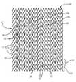
- FIG. 1is a flat pattern view of an intraluminal support frame according to a first exemplary embodiment shown in an expanded configuration.
- FIG. 2is a flat pattern view of the support frame illustrated in FIG. 1 shown in an unexpanded configuration.
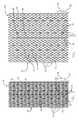
- FIG. 3is a flat pattern view of an intraluminal support frame according to a second exemplary embodiment shown in an expanded configuration.
- FIG. 4is a perspective view of a medical device according to a third exemplary embodiment.
- FIG. 5is an elevational view of a medical device according to a fourth exemplary embodiment.
- FIG. 6is an end view of the medical device illustrated in FIG. 5 .
- FIGS. 1 and 2illustrate an intraluminal support frame 10 according to a first exemplary embodiment of the invention.
- Each of FIGS. 1 and 2are flat pattern views of the support frame 10 .
- the flat pattern illustrated in the figuresis circularized along a lengthwise axis to form a cylindrical support frame that defines an interior passageway.
- the flat pattern viewsare presented simply to facilitate understanding of the architecture of the support frame. It is expressly understood that support frames in accordance with the invention do not need to be fabricated by circularizing a flat piece to form a cylindrical member. While this certainly is an acceptable method of fabrication for support frames according to the invention, any suitable method can be used. For example, an appropriate pattern can be cut from a tubular member to form a desirable pattern.
- the support frame 10comprises a plurality of ring structures 12 interconnected by first 14 and second 16 sets of connector segments.
- Each ring structure 12is a substantially circular ring comprising an endless undulating pattern.
- the undulating patterncomprises a serpentine pattern 18 .
- Any suitable ring structure with the desired undulating patterncan be used, including rings formed by bending a wire in a zig-zag pattern and joining the ends.
- a ring structurecan be formed by cutting a suitable pattern from a solid tube of material. Examples of suitable ring structures are described in U.S. Pat. Nos.
- the support frame 10can include any suitable number of ring structures 12 .
- the specific number of ring structures 12 included in a particular support frame according to the inventionwill depend on several factors, including the anticipated axial length of a treatment site at which the support frame may be deployed.
- the support frame illustrated in FIGS. 1 and 2includes sixteen ring structures. As a minimum, and based on the interrelationship between the sets 14 , 16 of connector segments and the ring structures 12 , a support frame according to the invention includes at least three ring structures.
- the first set 14 of connector segmentsjoin adjacent ring structures 12 . As best illustrated in FIG. 1 , an individual connector segment 20 of this set 14 extends between two adjacent ring structures 12 .
- the connector segment 20is advantageously terminated at each of the adjacent ring structures 12 to enhance the overall flexibility of the support frame 10 .
- the first set 14 of connector segmentscan include any suitable number of individual connector segments 20 .
- the specific number chosen for any particular support frame according to the inventionwill depend on several factors, including the desired flexibility of the support frame.
- first 22 and second 24 adjacent pairs of ring structures 12can have different numbers of first set 14 connector segments interconnecting the respective pairs of ring structures 12 .
- four (4) first set 14 connector segmentsinterconnect the ring structures 12 of the first pair 22 while six (6) first set 14 connector segments interconnect the ring structures 12 of the second pair 24 . This arrangement is considered advantageous at least because it allows for localized flexibility along the length of the support frame 10 .
- the first set 14 connector segments joining the first pair 22 of ring structures 12are advantageously disposed out of phase with the first set 14 connector segments joining the adjacent second pair 24 of ring structures 12 .
- This arrangementenhances the overall stability of the support frame 10 .
- the term “out of phase”describes a spatial relationship between connector segments in which the connector segments lie on different lengthwise axes.
- the second set 16 of connector segmentsjoin three or more adjacent ring structures 12 .
- individual connector segments 26 of the second set 16 of connector segmentsjoin all of the ring structures 12 in the support frame 10 .
- the individual connector segments 26 of the second set 16provide longitudinal stability to the support frame 10 and provide desirable foreshortening characteristics for the support frame 10 .
- the second set 16 of connector segmentscan include any suitable number of individual connector segments 26 .
- the specific number chosen for any particular support frame according to the inventionwill depend on several factors, including the desired longitudinal stability and flexibility of the support frame.
- the second set 16includes two individual connector segments 26 (note that, as a feature of the flat pattern nature of the drawings, one of the connector segments is split lengthwise). No matter the number chosen, the individual connector segments 26 of the second set 16 can be relatively positioned in any suitable manner.
- the individual connector segments 26 of the second set 16are diametrically opposed from each other in the cylindrical form of the support frame 10 . Other relative positioning of the individual connector segments 26 can be used, including localization of multiple connector segments 26 on one side of the support frame 10 .
- the second set 16 of connector segmentscan comprise a single individual connector segment 26 .
- peaks 28 of the undulating pattern 18 of a ring structure 12are disposed between an individual connector segment 26 of the second set 16 of connector segments and each individual connector segment 20 of the first set 14 of connector segments. More or fewer separating peaks 28 can be employed, but a minimum of two is considered advantageous. Also, different pairs of adjacent ring structures 12 can have different numbers of separating peaks. For example, in the embodiment illustrated in FIGS.
- three separating peaks 30are disposed between the first set 14 and second set 16 connector segments that join a first pair 22 of adjacent ring structures 12
- two separating peaks 32are disposed between the first set 14 and second set 16 connector segments that join a second pair 24 of adjacent ring structures 12 .
- the support frame 10is an expandable support frame having radially unexpanded and radially expanded configurations.
- the support frame 10can be a self-expandable support frame, such as one fabricated from a shape memory material such as nickel-titanium alloy, a balloon expandable support frame or any other type of expandable frame.
- FIG. 1illustrates the support frame 10 in its radially expanded configuration
- FIG. 2illustrates the support frame 10 in its radially unexpanded configuration.
- the support frame 10can be fabricated from any suitable material.
- the material chosen for any particular support frame according to the inventionneed only be biocompatible or able to be made biocompatible.
- suitable materialsinclude shape memory alloys, such as nickel-titanium alloys, and stainless steel.
- the ring members 12 and sets 14 , 16 of connector segmentscan be fabricated from the same or different materials using conventional techniques, including winding and braiding techniques as well as laser-cutting techniques.
- FIG. 3illustrates a support frame 110 according to a second exemplary embodiment.
- FIG. 3is a flat pattern view of the support frame 110 and illustrates the support frame 110 in a radially expanded configuration.
- the support frame 110is similar to the support frame 10 illustrated in FIGS. 1 and 2 , except as described below. Accordingly, similar features and/or components are labeled with similar reference numbers as those in FIGS. 1 and 2 , increased by one hundred.
- the support frame 110comprises a plurality of ring structures 112 interconnected by first 114 and second 116 sets of connector segments. Each ring structure 112 has an endless undulating pattern 118 . Individual connector segments 120 of the first set of connector segments 114 join a pair of adjacent ring structures 112 . Individual connector segments 126 of the second set of connector segments 116 join three or more adjacent ring structures 112 .
- each of the individual connector segments 126 of the second set 116 of connector segmentsjoins fewer than all of the ring structures 112 that form the support frame 110 .
- each of the individual connector segments 126 of the second set 116 of connector segmentscan join less than one half of the ring structures 112 that form the support frame 110 .
- each of the individual connector segments 126 of the second set 116 of connector segmentscan join fewer than one third of the ring structures 112 that form the support frame, or any other suitable number of ring structures 112 that is less than the total number of ring structures 112 in the support frame 110 .
- This arrangement of the second set 116 of connector segmentsforms first 150 and second 160 regions on the support frame 110 .
- the first region 150includes connector segments from both sets 114 , 116
- the second region 160includes only connector segments from the first set 114 .
- the first region 150has enhanced longitudinal stability compared to the second region 160 , and exhibits enhanced foreshortening characteristics over those of the second region 160 .
- This differential architecturemay be desirable in a variety of applications, including medical devices with functional members, such as graft members and/or valve members, attached to a support frame. An example of such a medical device is described below. Also, this arrangement can be advantageous in applications in which a localization of foreshortening is desired along a portion of the length of a medical device.
- FIG. 4illustrates a medical device 200 according to an exemplary embodiment.
- the medical device 200includes a support frame 210 according to the invention and an attached graft member 270 .
- the support frame 210is the support frame 10 illustrated in FIGS. 1 and 2 . Accordingly, similar features and/or components are labeled with similar reference numbers as those in FIGS. 1 and 2 , increased by two hundred.
- the support frame 210comprises a plurality of ring structures 212 interconnected by first 214 and second 216 sets of connector segments. Each ring structure 212 has an endless undulating pattern 218 . Individual connector segments 220 of the first set 214 of connector segments join a pair of adjacent ring structures 212 . Individual connector segments 226 of the second set 216 of connector segments join all ring structures 212 of the support frame 210 .
- the medical device 200can include any support frame according to the invention.
- the graft member 270is attached to the support frame 210 and is disposed around the support frame 210 and along its entire length. It is understood that the graft member 270 can be disposed around any suitable portion of the support frame 210 and along any suitable length of the support frame 210 . Also, the graft member 270 can be disposed on the exterior, the interior, or both the exterior and interior of the support frame 210 .
- the graft member 270can be formed of any suitable material, and need only be biocompatible or be able to be made biocompatible.
- the medical device artsinclude several examples of suitable materials for use as or in the graft member.
- the specific material chosen for the graft member in a particular medical device according to the inventionwill depend on several factors, including the anticipated point of treatment and/or vessel type at which the medical device will be used.
- suitable materialsinclude expanded polytetrafluoroethylene (ePTFF), polyurethane, and bioremodellable materials such as, extracellular matrix (ECM) materials, including small intestine submucosa (SIS) and other ECM's.
- ECMextracellular matrix
- SISsmall intestine submucosa
- Other bioremodellable materialscan be used as well.
- Tissues and other natural materialscan also be used, including processed versions of natural materials, including fixed tissue.
- the graft member 270is attached to the support frame 210 by attachment elements 280 .
- Any suitable type and number of attachment elements 280can be used, including sutures, staples, clips, adhesives, and the like.
- the graft member 270is advantageously attached to the support frame 210 at one or more points along the individual connector segments 226 of the second set 216 of connector segments 216 . It is expressly understood, though, that the attachment elements 280 can be positioned at any point on the medical device 200 and support frame 210 .
- the medical device 200is useful as a supported graft, such as a stent graft, and can be used in a variety of applications, including vessel repair and aneurysm exclusion.
- FIGS. 5 and 6illustrate a medical device 300 according to an exemplary embodiment.
- the medical device 300according to this embodiment is a prosthetic valve that can be used to regulate fluid flow through a body vessel.
- the medical device 300can be used in a blood vessel, such as a vein, or in any other suitable body vessel.
- the medical device 300can be used in and/or with a body organ, such as a heart, to provide a valve for the organ and/or augment, replace, or otherwise treat a natural valve associated with the organ.
- the medical device 300includes a support frame 310 according to the invention and an attached valve member 390 .
- the support frame 310comprises a plurality of ring structures 312 interconnected by first 314 and second 316 sets of connector segments.
- Each of the ring structures 312has an endless undulating pattern 318 .
- Individual connector segments 320 of the first set 314 of connector segmentsjoin an adjacent pair of ring structures 312
- individual connector segments 326 of the second set of connector segments 316join three or more adjacent ring structures 312 .
- the support frame 310includes first 350 and second 360 regions, similar to the support frame illustrated in FIGS. 3 and 4 .
- the first region 350includes connector segments from both the first 314 and second sets 316 of connector segments
- the second region 360includes only connector segments from the first set 314 of connector segments.
- the valve member 390is attached to the support frame 310 at the first region and advantageously along a portion of the length of one or more connector segments 326 of the second set 316 of connector segments.
- Attachment elements 392are used to connect the graft member 390 to the support frame 310 . Any suitable type and number of attachment elements, including sutures, staples, clips, adhesives and the like, can be used.
- valve member 390is attached to the support frame 310 in a manner that allows the valve member 390 to form a valve opening 394 that alternately opens and closes to allow and substantially prevent, respectively, fluid flow through the medical device 300 .
- the valve member 390can comprise a single member, such as a tubular member, or multiple members, such as multiple valve leaflets.
- the valve member 290need only be attached to the support frame in a manner that forms the desired valve opening 394 .
- any suitable materialcan be used for the valve member 390 , including natural and synthetic materials.
- the specific material chosen for a particular medical device according to the inventionwill depend on several factors, including the intended point of treatment and vessel type at which the medical device will be used and the intended function of the medical device.
- suitable materialsinclude polymeric materials, such as polyurethane, and bioremodellable materials, such as SIS and other ECM's. ECM's are considered particularly advantageous at least because of their ability to be tolerated in a variety of in vivo environments and their ability to remodel into natural host tissue.
- Other currently contemplated materialsinclude bovine pericardium and other natural materials.
- Tissue valveswhich comprise preexisting natural valves harvested from animal tissue, such as a heart or other valve-containing or defining tissue, can be used, as can other suitable tissues or sections thereof.
- Porcine heart valvesare considered particularly well-suited tissue valves for use in medical devices according to the invention.
- Tissues and other natural materialscan be used in their natural state or in a processed form, such as a form rendered substantially biologically inert by chemical treatment.
- a cross-linked ECMsuch as cross-linked SIS, can be used.
Landscapes
- Health & Medical Sciences (AREA)
- Biomedical Technology (AREA)
- Engineering & Computer Science (AREA)
- Cardiology (AREA)
- Heart & Thoracic Surgery (AREA)
- Oral & Maxillofacial Surgery (AREA)
- Transplantation (AREA)
- Vascular Medicine (AREA)
- Life Sciences & Earth Sciences (AREA)
- Animal Behavior & Ethology (AREA)
- General Health & Medical Sciences (AREA)
- Public Health (AREA)
- Veterinary Medicine (AREA)
- Optics & Photonics (AREA)
- Physics & Mathematics (AREA)
- Prostheses (AREA)
Abstract
Description
Claims (15)
Priority Applications (1)
| Application Number | Priority Date | Filing Date | Title |
|---|---|---|---|
| US12/463,394US8123794B2 (en) | 2004-12-20 | 2009-05-09 | Intraluminal support frame |
Applications Claiming Priority (3)
| Application Number | Priority Date | Filing Date | Title |
|---|---|---|---|
| US59319504P | 2004-12-20 | 2004-12-20 | |
| US11/314,661US7544205B2 (en) | 2004-12-20 | 2005-12-20 | Intraluminal support frame and medical devices including the support frame |
| US12/463,394US8123794B2 (en) | 2004-12-20 | 2009-05-09 | Intraluminal support frame |
Related Parent Applications (1)
| Application Number | Title | Priority Date | Filing Date |
|---|---|---|---|
| US11/314,661ContinuationUS7544205B2 (en) | 2004-12-20 | 2005-12-20 | Intraluminal support frame and medical devices including the support frame |
Publications (2)
| Publication Number | Publication Date |
|---|---|
| US20090216311A1 US20090216311A1 (en) | 2009-08-27 |
| US8123794B2true US8123794B2 (en) | 2012-02-28 |
Family
ID=36121447
Family Applications (2)
| Application Number | Title | Priority Date | Filing Date |
|---|---|---|---|
| US11/314,661Active2026-06-23US7544205B2 (en) | 2004-12-20 | 2005-12-20 | Intraluminal support frame and medical devices including the support frame |
| US12/463,394Active2026-06-03US8123794B2 (en) | 2004-12-20 | 2009-05-09 | Intraluminal support frame |
Family Applications Before (1)
| Application Number | Title | Priority Date | Filing Date |
|---|---|---|---|
| US11/314,661Active2026-06-23US7544205B2 (en) | 2004-12-20 | 2005-12-20 | Intraluminal support frame and medical devices including the support frame |
Country Status (3)
| Country | Link |
|---|---|
| US (2) | US7544205B2 (en) |
| EP (1) | EP1848368A1 (en) |
| WO (1) | WO2006069094A1 (en) |
Cited By (6)
| Publication number | Priority date | Publication date | Assignee | Title |
|---|---|---|---|---|
| US20110135806A1 (en)* | 2009-12-03 | 2011-06-09 | David Grewe | Manufacturing methods for covering endoluminal prostheses |
| EP2708208A2 (en) | 2012-09-14 | 2014-03-19 | Cook Medical Technologies LLC | Endoluminal prosthesis |
| EP2749248A1 (en) | 2012-12-28 | 2014-07-02 | Cook Medical Technologies LLC | Endoluminal prosthesis with fiber matrix |
| US8795577B2 (en) | 2007-11-30 | 2014-08-05 | Cook Medical Technologies Llc | Needle-to-needle electrospinning |
| US9175427B2 (en) | 2011-11-14 | 2015-11-03 | Cook Medical Technologies Llc | Electrospun patterned stent graft covering |
| EP3040090A1 (en) | 2014-12-31 | 2016-07-06 | Cook Medical Technologies LLC | Medical devices and methods of making |
Families Citing this family (150)
| Publication number | Priority date | Publication date | Assignee | Title |
|---|---|---|---|---|
| US6440164B1 (en) | 1999-10-21 | 2002-08-27 | Scimed Life Systems, Inc. | Implantable prosthetic valve |
| US8038708B2 (en) | 2001-02-05 | 2011-10-18 | Cook Medical Technologies Llc | Implantable device with remodelable material and covering material |
| AU2003285943B2 (en) | 2002-10-24 | 2008-08-21 | Boston Scientific Limited | Venous valve apparatus and method |
| US6945957B2 (en) | 2002-12-30 | 2005-09-20 | Scimed Life Systems, Inc. | Valve treatment catheter and methods |
| US7854761B2 (en) | 2003-12-19 | 2010-12-21 | Boston Scientific Scimed, Inc. | Methods for venous valve replacement with a catheter |
| US8128681B2 (en) | 2003-12-19 | 2012-03-06 | Boston Scientific Scimed, Inc. | Venous valve apparatus, system, and method |
| US7971333B2 (en) | 2006-05-30 | 2011-07-05 | Advanced Cardiovascular Systems, Inc. | Manufacturing process for polymetric stents |
| US20140107761A1 (en) | 2004-07-26 | 2014-04-17 | Abbott Cardiovascular Systems Inc. | Biodegradable stent with enhanced fracture toughness |
| US8747879B2 (en) | 2006-04-28 | 2014-06-10 | Advanced Cardiovascular Systems, Inc. | Method of fabricating an implantable medical device to reduce chance of late inflammatory response |
| US7731890B2 (en) | 2006-06-15 | 2010-06-08 | Advanced Cardiovascular Systems, Inc. | Methods of fabricating stents with enhanced fracture toughness |
| US7566343B2 (en) | 2004-09-02 | 2009-07-28 | Boston Scientific Scimed, Inc. | Cardiac valve, system, and method |
| WO2006069094A1 (en)* | 2004-12-20 | 2006-06-29 | Cook Incorporated | Intraluminal support frame and medical devices including the support frame |
| US20060173490A1 (en) | 2005-02-01 | 2006-08-03 | Boston Scientific Scimed, Inc. | Filter system and method |
| US7867274B2 (en) | 2005-02-23 | 2011-01-11 | Boston Scientific Scimed, Inc. | Valve apparatus, system and method |
| US7722666B2 (en) | 2005-04-15 | 2010-05-25 | Boston Scientific Scimed, Inc. | Valve apparatus, system and method |
| US8012198B2 (en) | 2005-06-10 | 2011-09-06 | Boston Scientific Scimed, Inc. | Venous valve, system, and method |
| US7569071B2 (en) | 2005-09-21 | 2009-08-04 | Boston Scientific Scimed, Inc. | Venous valve, system, and method with sinus pocket |
| JP4871692B2 (en)* | 2006-09-29 | 2012-02-08 | テルモ株式会社 | In vivo indwelling stent and biological organ dilator |
| WO2008091493A1 (en) | 2007-01-08 | 2008-07-31 | California Institute Of Technology | In-situ formation of a valve |
| US7967853B2 (en) | 2007-02-05 | 2011-06-28 | Boston Scientific Scimed, Inc. | Percutaneous valve, system and method |
| US8303644B2 (en) | 2007-05-04 | 2012-11-06 | Abbott Cardiovascular Systems Inc. | Stents with high radial strength and methods of manufacturing same |
| US8728154B2 (en) | 2007-08-24 | 2014-05-20 | St. Jude Medical, Inc. | Prosthetic aortic heart valves |
| EP3443938B1 (en) | 2007-09-26 | 2024-01-24 | St. Jude Medical, LLC | Collapsible prosthetic heart valves |
| WO2009045334A1 (en) | 2007-09-28 | 2009-04-09 | St. Jude Medical, Inc. | Collapsible/expandable prosthetic heart valves with native calcified leaflet retention features |
| US9532868B2 (en) | 2007-09-28 | 2017-01-03 | St. Jude Medical, Inc. | Collapsible-expandable prosthetic heart valves with structures for clamping native tissue |
| US7892276B2 (en) | 2007-12-21 | 2011-02-22 | Boston Scientific Scimed, Inc. | Valve with delayed leaflet deployment |
| EP2815724B2 (en) | 2008-07-15 | 2024-03-13 | St. Jude Medical, Inc. | Collapsible and re-expandable prosthetic heart valve cuff designs and complementary technological applications |
| WO2010011878A2 (en)* | 2008-07-24 | 2010-01-28 | Cook Incorporated | Valve device with biased leaflets |
| AU2010218384B2 (en) | 2009-02-27 | 2014-11-20 | St. Jude Medical, Inc. | Stent features for collapsible prosthetic heart valves |
| US8568471B2 (en) | 2010-01-30 | 2013-10-29 | Abbott Cardiovascular Systems Inc. | Crush recoverable polymer scaffolds |
| US8808353B2 (en) | 2010-01-30 | 2014-08-19 | Abbott Cardiovascular Systems Inc. | Crush recoverable polymer scaffolds having a low crossing profile |
| US9795476B2 (en) | 2010-06-17 | 2017-10-24 | St. Jude Medical, Llc | Collapsible heart valve with angled frame |
| US9039759B2 (en) | 2010-08-24 | 2015-05-26 | St. Jude Medical, Cardiology Division, Inc. | Repositioning of prosthetic heart valve and deployment |
| US8814931B2 (en) | 2010-08-24 | 2014-08-26 | St. Jude Medical, Cardiology Division, Inc. | Staged deployment devices and methods for transcatheter heart valve delivery systems |
| WO2012036741A2 (en) | 2010-09-17 | 2012-03-22 | St. Jude Medical, Cardiology Division, Inc. | Staged deployment devices and methods for transcatheter heart valve delivery |
| USD654169S1 (en) | 2010-09-20 | 2012-02-14 | St. Jude Medical Inc. | Forked ends |
| USD660433S1 (en) | 2010-09-20 | 2012-05-22 | St. Jude Medical, Inc. | Surgical stent assembly |
| USD654170S1 (en) | 2010-09-20 | 2012-02-14 | St. Jude Medical, Inc. | Stent connections |
| USD653341S1 (en) | 2010-09-20 | 2012-01-31 | St. Jude Medical, Inc. | Surgical stent |
| USD684692S1 (en) | 2010-09-20 | 2013-06-18 | St. Jude Medical, Inc. | Forked ends |
| USD660967S1 (en) | 2010-09-20 | 2012-05-29 | St. Jude Medical, Inc. | Surgical stent |
| USD648854S1 (en) | 2010-09-20 | 2011-11-15 | St. Jude Medical, Inc. | Commissure points |
| AU2011306028B2 (en) | 2010-09-20 | 2014-07-17 | St. Jude Medical, Cardiology Division, Inc. | Valve leaflet attachment in collapsible prosthetic valves |
| USD652926S1 (en) | 2010-09-20 | 2012-01-24 | St. Jude Medical, Inc. | Forked end |
| USD653342S1 (en) | 2010-09-20 | 2012-01-31 | St. Jude Medical, Inc. | Stent connections |
| USD652927S1 (en) | 2010-09-20 | 2012-01-24 | St. Jude Medical, Inc. | Surgical stent |
| USD653343S1 (en) | 2010-09-20 | 2012-01-31 | St. Jude Medical, Inc. | Surgical cuff |
| USD660432S1 (en) | 2010-09-20 | 2012-05-22 | St. Jude Medical, Inc. | Commissure point |
| US9717593B2 (en) | 2011-02-01 | 2017-08-01 | St. Jude Medical, Cardiology Division, Inc. | Leaflet suturing to commissure points for prosthetic heart valve |
| US10285798B2 (en) | 2011-06-03 | 2019-05-14 | Merit Medical Systems, Inc. | Esophageal stent |
| US8726483B2 (en) | 2011-07-29 | 2014-05-20 | Abbott Cardiovascular Systems Inc. | Methods for uniform crimping and deployment of a polymer scaffold |
| US9668859B2 (en) | 2011-08-05 | 2017-06-06 | California Institute Of Technology | Percutaneous heart valve delivery systems |
| US9060860B2 (en) | 2011-08-18 | 2015-06-23 | St. Jude Medical, Cardiology Division, Inc. | Devices and methods for transcatheter heart valve delivery |
| US8986368B2 (en) | 2011-10-31 | 2015-03-24 | Merit Medical Systems, Inc. | Esophageal stent with valve |
| EP3281608B1 (en) | 2012-02-10 | 2020-09-16 | CVDevices, LLC | Medical product comprising a frame and visceral pleura |
| KR102313261B1 (en) | 2012-06-05 | 2021-10-14 | 메리트 메디컬 시스템즈, 인크. | Esophageal stent |
| US9289292B2 (en) | 2012-06-28 | 2016-03-22 | St. Jude Medical, Cardiology Division, Inc. | Valve cuff support |
| US9554902B2 (en) | 2012-06-28 | 2017-01-31 | St. Jude Medical, Cardiology Division, Inc. | Leaflet in configuration for function in various shapes and sizes |
| US20140005776A1 (en) | 2012-06-29 | 2014-01-02 | St. Jude Medical, Cardiology Division, Inc. | Leaflet attachment for function in various shapes and sizes |
| US9241791B2 (en) | 2012-06-29 | 2016-01-26 | St. Jude Medical, Cardiology Division, Inc. | Valve assembly for crimp profile |
| US9615920B2 (en) | 2012-06-29 | 2017-04-11 | St. Jude Medical, Cardiology Divisions, Inc. | Commissure attachment feature for prosthetic heart valve |
| US9808342B2 (en) | 2012-07-03 | 2017-11-07 | St. Jude Medical, Cardiology Division, Inc. | Balloon sizing device and method of positioning a prosthetic heart valve |
| US10004597B2 (en) | 2012-07-03 | 2018-06-26 | St. Jude Medical, Cardiology Division, Inc. | Stent and implantable valve incorporating same |
| JP6463265B2 (en) | 2012-07-20 | 2019-01-30 | クック・メディカル・テクノロジーズ・リミテッド・ライアビリティ・カンパニーCook Medical Technologies Llc | Implantable medical device having a sleeve |
| US9801721B2 (en) | 2012-10-12 | 2017-10-31 | St. Jude Medical, Cardiology Division, Inc. | Sizing device and method of positioning a prosthetic heart valve |
| US10524909B2 (en) | 2012-10-12 | 2020-01-07 | St. Jude Medical, Cardiology Division, Inc. | Retaining cage to permit resheathing of a tavi aortic-first transapical system |
| US9655719B2 (en) | 2013-01-29 | 2017-05-23 | St. Jude Medical, Cardiology Division, Inc. | Surgical heart valve flexible stent frame stiffener |
| US9186238B2 (en) | 2013-01-29 | 2015-11-17 | St. Jude Medical, Cardiology Division, Inc. | Aortic great vessel protection |
| US9314163B2 (en) | 2013-01-29 | 2016-04-19 | St. Jude Medical, Cardiology Division, Inc. | Tissue sensing device for sutureless valve selection |
| CA2900862C (en) | 2013-02-11 | 2017-10-03 | Cook Medical Technologies Llc | Expandable support frame and medical device |
| US9844435B2 (en) | 2013-03-01 | 2017-12-19 | St. Jude Medical, Cardiology Division, Inc. | Transapical mitral valve replacement |
| US9901470B2 (en) | 2013-03-01 | 2018-02-27 | St. Jude Medical, Cardiology Division, Inc. | Methods of repositioning a transcatheter heart valve after full deployment |
| EP2964148A4 (en) | 2013-03-05 | 2016-08-24 | Merit Medical Systems Inc | REINFORCED VALVE |
| US9480563B2 (en) | 2013-03-08 | 2016-11-01 | St. Jude Medical, Cardiology Division, Inc. | Valve holder with leaflet protection |
| US10271949B2 (en) | 2013-03-12 | 2019-04-30 | St. Jude Medical, Cardiology Division, Inc. | Paravalvular leak occlusion device for self-expanding heart valves |
| US10314698B2 (en) | 2013-03-12 | 2019-06-11 | St. Jude Medical, Cardiology Division, Inc. | Thermally-activated biocompatible foam occlusion device for self-expanding heart valves |
| EP2967849B1 (en) | 2013-03-12 | 2025-08-13 | St. Jude Medical, Cardiology Division, Inc. | Self-actuating sealing portions for paravalvular leak protection |
| US9636222B2 (en) | 2013-03-12 | 2017-05-02 | St. Jude Medical, Cardiology Division, Inc. | Paravalvular leak protection |
| US9339274B2 (en) | 2013-03-12 | 2016-05-17 | St. Jude Medical, Cardiology Division, Inc. | Paravalvular leak occlusion device for self-expanding heart valves |
| US9398951B2 (en) | 2013-03-12 | 2016-07-26 | St. Jude Medical, Cardiology Division, Inc. | Self-actuating sealing portions for paravalvular leak protection |
| US9326856B2 (en) | 2013-03-14 | 2016-05-03 | St. Jude Medical, Cardiology Division, Inc. | Cuff configurations for prosthetic heart valve |
| US9131982B2 (en) | 2013-03-14 | 2015-09-15 | St. Jude Medical, Cardiology Division, Inc. | Mediguide-enabled renal denervation system for ensuring wall contact and mapping lesion locations |
| WO2014144247A1 (en) | 2013-03-15 | 2014-09-18 | Arash Kheradvar | Handle mechanism and functionality for repositioning and retrieval of transcatheter heart valves |
| WO2014150130A1 (en) | 2013-03-15 | 2014-09-25 | Merit Medical Systems, Inc. | Esophageal stent |
| WO2014204807A1 (en) | 2013-06-19 | 2014-12-24 | Aga Medical Corporation | Collapsible valve having paravalvular leak protection |
| US9668856B2 (en) | 2013-06-26 | 2017-06-06 | St. Jude Medical, Cardiology Division, Inc. | Puckering seal for reduced paravalvular leakage |
| USD730521S1 (en) | 2013-09-04 | 2015-05-26 | St. Jude Medical, Cardiology Division, Inc. | Stent with commissure attachments |
| USD730520S1 (en) | 2013-09-04 | 2015-05-26 | St. Jude Medical, Cardiology Division, Inc. | Stent with commissure attachments |
| US9867611B2 (en) | 2013-09-05 | 2018-01-16 | St. Jude Medical, Cardiology Division, Inc. | Anchoring studs for transcatheter valve implantation |
| US10117742B2 (en) | 2013-09-12 | 2018-11-06 | St. Jude Medical, Cardiology Division, Inc. | Stent designs for prosthetic heart valves |
| US9913715B2 (en) | 2013-11-06 | 2018-03-13 | St. Jude Medical, Cardiology Division, Inc. | Paravalvular leak sealing mechanism |
| EP4176844B1 (en) | 2013-11-06 | 2025-08-20 | St. Jude Medical, Cardiology Division, Inc. | Reduced profile prosthetic heart valve |
| EP2870946B1 (en) | 2013-11-06 | 2018-10-31 | St. Jude Medical, Cardiology Division, Inc. | Paravalvular leak sealing mechanism |
| WO2015073287A1 (en) | 2013-11-12 | 2015-05-21 | St. Jude Medical, Cardiology Division, Inc. | Pneumatically power-assisted tavi delivery system |
| WO2015077274A1 (en) | 2013-11-19 | 2015-05-28 | St. Jude Medical, Cardiology Division, Inc. | Sealing structures for paravalvular leak protection |
| US10314693B2 (en) | 2013-11-27 | 2019-06-11 | St. Jude Medical, Cardiology Division, Inc. | Cuff stitching reinforcement |
| US9597185B2 (en) | 2013-12-19 | 2017-03-21 | St. Jude Medical, Cardiology Division, Inc. | Leaflet-cuff attachments for prosthetic heart valve |
| US20150209141A1 (en) | 2014-01-24 | 2015-07-30 | St. Jude Medical, Cardiology Division, Inc. | Stationary intra-annular halo designs for paravalvular leak (pvl) reduction-passive channel filling cuff designs |
| US9820852B2 (en) | 2014-01-24 | 2017-11-21 | St. Jude Medical, Cardiology Division, Inc. | Stationary intra-annular halo designs for paravalvular leak (PVL) reduction—active channel filling cuff designs |
| US9867556B2 (en) | 2014-02-07 | 2018-01-16 | St. Jude Medical, Cardiology Division, Inc. | System and method for assessing dimensions and eccentricity of valve annulus for trans-catheter valve implantation |
| US10292711B2 (en) | 2014-02-07 | 2019-05-21 | St. Jude Medical, Cardiology Division, Inc. | Mitral valve treatment device having left atrial appendage closure |
| WO2015126712A1 (en) | 2014-02-18 | 2015-08-27 | St. Jude Medical, Cardiology Division, Inc. | Bowed runners for paravalvular leak protection |
| US10085834B2 (en) | 2014-03-18 | 2018-10-02 | St. Jude Medical, Cardiology Divsion, Inc. | Mitral valve replacement toggle cell securement |
| US9763778B2 (en) | 2014-03-18 | 2017-09-19 | St. Jude Medical, Cardiology Division, Inc. | Aortic insufficiency valve percutaneous valve anchoring |
| US9610157B2 (en) | 2014-03-21 | 2017-04-04 | St. Jude Medical, Cardiology Division, Inc. | Leaflet abrasion mitigation |
| EP3122289A1 (en) | 2014-03-26 | 2017-02-01 | St. Jude Medical, Cardiology Division, Inc. | Transcatheter mitral valve stent frames |
| WO2015152980A1 (en) | 2014-03-31 | 2015-10-08 | St. Jude Medical, Cardiology Division, Inc. | Paravalvular sealing via extended cuff mechanisms |
| EP3131504B1 (en) | 2014-04-14 | 2023-03-15 | St. Jude Medical, Cardiology Division, Inc. | Leaflet abrasion mitigation in prosthetic heart valves |
| ES2795358T3 (en) | 2014-05-16 | 2020-11-23 | St Jude Medical Cardiology Div Inc | Subannular sealing for paravalvular leak protection |
| EP3142604B1 (en) | 2014-05-16 | 2024-01-10 | St. Jude Medical, Cardiology Division, Inc. | Transcatheter valve with paravalvular leak sealing ring |
| US9757230B2 (en) | 2014-05-16 | 2017-09-12 | St. Jude Medical, Cardiology Division, Inc. | Stent assembly for use in prosthetic heart valves |
| WO2015179473A1 (en) | 2014-05-22 | 2015-11-26 | St. Jude Medical, Cardiology Division, Inc. | Stents with anchoring sections |
| EP2954875B1 (en) | 2014-06-10 | 2017-11-15 | St. Jude Medical, Cardiology Division, Inc. | Stent cell bridge for cuff attachment |
| EP3182927B1 (en) | 2014-08-18 | 2024-11-13 | St. Jude Medical, Cardiology Division, Inc. | Prosthetic heart devices having diagnostic capabilities |
| US9737264B2 (en) | 2014-08-18 | 2017-08-22 | St. Jude Medical, Cardiology Division, Inc. | Sensors for prosthetic heart devices |
| WO2016028583A1 (en) | 2014-08-18 | 2016-02-25 | St. Jude Medical, Cardiology Division, Inc. | Sensors for prosthetic heart devices |
| US20160095701A1 (en)* | 2014-10-07 | 2016-04-07 | St. Jude Medical, Cardiology Division, Inc. | Bi-Leaflet Mitral Valve Design |
| US10314699B2 (en) | 2015-03-13 | 2019-06-11 | St. Jude Medical, Cardiology Division, Inc. | Recapturable valve-graft combination and related methods |
| EP3273912A1 (en) | 2015-03-23 | 2018-01-31 | St. Jude Medical, Cardiology Division, Inc. | Heart valve repair |
| US9962260B2 (en) | 2015-03-24 | 2018-05-08 | St. Jude Medical, Cardiology Division, Inc. | Prosthetic mitral valve |
| US10070954B2 (en) | 2015-03-24 | 2018-09-11 | St. Jude Medical, Cardiology Division, Inc. | Mitral heart valve replacement |
| US10716672B2 (en) | 2015-04-07 | 2020-07-21 | St. Jude Medical, Cardiology Division, Inc. | System and method for intraprocedural assessment of geometry and compliance of valve annulus for trans-catheter valve implantation |
| EP3307207A1 (en) | 2015-06-12 | 2018-04-18 | St. Jude Medical, Cardiology Division, Inc. | Heart valve repair and replacement |
| US10639149B2 (en) | 2015-07-16 | 2020-05-05 | St. Jude Medical, Cardiology Division, Inc. | Sutureless prosthetic heart valve |
| WO2017027541A1 (en) | 2015-08-12 | 2017-02-16 | St. Jude Medical, Cardiology Division, Inc. | Collapsible heart valve including stents with tapered struts |
| WO2017196909A1 (en) | 2016-05-12 | 2017-11-16 | St. Jude Medical, Cardiology Division, Inc. | Mitral heart valve replacement |
| EP3454785B1 (en) | 2016-05-13 | 2021-11-17 | St. Jude Medical, Cardiology Division, Inc. | Heart valve with stent having varying cell densities |
| USD802764S1 (en) | 2016-05-13 | 2017-11-14 | St. Jude Medical, Cardiology Division, Inc. | Surgical stent |
| USD802766S1 (en) | 2016-05-13 | 2017-11-14 | St. Jude Medical, Cardiology Division, Inc. | Surgical stent |
| USD802765S1 (en) | 2016-05-13 | 2017-11-14 | St. Jude Medical, Cardiology Division, Inc. | Surgical stent |
| US10548722B2 (en) | 2016-08-26 | 2020-02-04 | St. Jude Medical, Cardiology Division, Inc. | Prosthetic heart valve with paravalvular leak mitigation features |
| US10456249B2 (en) | 2016-09-15 | 2019-10-29 | St. Jude Medical, Cardiology Division, Inc. | Prosthetic heart valve with paravalvular leak mitigation features |
| EP3531977B1 (en) | 2016-10-28 | 2024-06-26 | St. Jude Medical, Cardiology Division, Inc. | Prosthetic mitral valve |
| WO2018102520A1 (en) | 2016-12-02 | 2018-06-07 | St. Jude Medical, Cardiology Division, Inc. | Transcatheter delivery system with transverse wheel actuation |
| WO2018102525A1 (en) | 2016-12-02 | 2018-06-07 | St. Jude Medical, Cardiology Division, Inc. | Transcatheter delivery system with two modes of actuation |
| WO2018160790A1 (en) | 2017-03-03 | 2018-09-07 | St. Jude Medical, Cardiology Division, Inc. | Transcatheter mitral valve design |
| USD875250S1 (en) | 2017-05-15 | 2020-02-11 | St. Jude Medical, Cardiology Division, Inc. | Stent having tapered aortic struts |
| USD875935S1 (en) | 2017-05-15 | 2020-02-18 | St. Jude Medical, Cardiology Division, Inc. | Stent having tapered struts |
| WO2018213091A1 (en) | 2017-05-15 | 2018-11-22 | St. Jude Medical, Cardiology Division, Inc. | Transcatheter delivery system with wheel actuation |
| USD889653S1 (en) | 2017-05-15 | 2020-07-07 | St. Jude Medical, Cardiology Division, Inc. | Stent having tapered struts |
| US11382751B2 (en) | 2017-10-24 | 2022-07-12 | St. Jude Medical, Cardiology Division, Inc. | Self-expandable filler for mitigating paravalvular leak |
| US11813413B2 (en) | 2018-03-27 | 2023-11-14 | St. Jude Medical, Cardiology Division, Inc. | Radiopaque outer cuff for transcatheter valve |
| US11234812B2 (en) | 2018-04-18 | 2022-02-01 | St. Jude Medical, Cardiology Division, Inc. | Methods for surgical valve expansion |
| WO2020060828A1 (en) | 2018-09-20 | 2020-03-26 | St. Jude Medical, Cardiology Division, Inc. | Attachment of leaflets to prosthetic heart valve |
| US11364117B2 (en) | 2018-10-15 | 2022-06-21 | St. Jude Medical, Cardiology Division, Inc. | Braid connections for prosthetic heart valves |
| US11471277B2 (en) | 2018-12-10 | 2022-10-18 | St. Jude Medical, Cardiology Division, Inc. | Prosthetic tricuspid valve replacement design |
| EP3902503B1 (en) | 2018-12-26 | 2025-01-29 | St. Jude Medical, Cardiology Division, Inc. | Elevated outer cuff for reducing paravalvular leakage and increasing stent fatigue life |
| EP4003230B1 (en) | 2019-07-31 | 2024-12-04 | St. Jude Medical, Cardiology Division, Inc. | Alternate stent caf design for tavr |
| US12427018B2 (en) | 2020-05-11 | 2025-09-30 | St. Jude Medical, Cardiology Division, Inc. | Transcatheter mitral valve fixation concepts |
| WO2022015634A1 (en) | 2020-07-15 | 2022-01-20 | Tendyne Holdings, Inc. | Tether attachment for mitral valve |
Citations (25)
| Publication number | Priority date | Publication date | Assignee | Title |
|---|---|---|---|---|
| US4580568A (en) | 1984-10-01 | 1986-04-08 | Cook, Incorporated | Percutaneous endovascular stent and method for insertion thereof |
| US5411552A (en) | 1990-05-18 | 1995-05-02 | Andersen; Henning R. | Valve prothesis for implantation in the body and a catheter for implanting such valve prothesis |
| US5836966A (en)* | 1997-05-22 | 1998-11-17 | Scimed Life Systems, Inc. | Variable expansion force stent |
| FR2785174A1 (en) | 1998-11-03 | 2000-05-05 | Jacques Seguin | BODY CONDUIT EXTENSIONER, ESPECIALLY VASCULAR |
| US6261318B1 (en)* | 1995-07-25 | 2001-07-17 | Medstent Inc. | Expandable stent |
| WO2001074273A1 (en) | 2000-03-30 | 2001-10-11 | Advanced Cardiovascular Systems, Inc. | Bifurcated stent system |
| US20020138131A1 (en) | 2001-03-20 | 2002-09-26 | Solovay Kenneth S. | Rail stent |
| US6482228B1 (en) | 2000-11-14 | 2002-11-19 | Troy R. Norred | Percutaneous aortic valve replacement |
| US6494909B2 (en) | 2000-12-01 | 2002-12-17 | Prodesco, Inc. | Endovascular valve |
| US20030176914A1 (en) | 2003-01-21 | 2003-09-18 | Rabkin Dmitry J. | Multi-segment modular stent and methods for manufacturing stents |
| US20030225449A1 (en) | 2002-05-30 | 2003-12-04 | Denison Andy E. | Intravascular stents |
| US20030236568A1 (en) | 2002-05-10 | 2003-12-25 | Hikmat Hojeibane | Multi-lobed frame based unidirectional flow prosthetic implant |
| US20040093070A1 (en) | 2002-05-10 | 2004-05-13 | Hikmat Hojeibane | Frame based unidirectional flow prosthetic implant |
| WO2004045703A1 (en) | 2002-11-21 | 2004-06-03 | Independent Administrative Institution National Institute For Materials Science | Medical instrument for soft tissue and method for manufacture thereof |
| US6786922B2 (en) | 2002-10-08 | 2004-09-07 | Cook Incorporated | Stent with ring architecture and axially displaced connector segments |
| US20040210306A1 (en) | 2003-04-17 | 2004-10-21 | Quijano Rodolfo C. | Device for reduction of pressure effects of cardiac tricuspid valve regurgitation |
| US20040225348A1 (en) | 2003-04-08 | 2004-11-11 | Case Brian C. | Intraluminal support device with graft |
| US20040225356A1 (en) | 2003-05-09 | 2004-11-11 | Frater Robert W. | Flexible heart valve |
| US20040243216A1 (en) | 2003-05-28 | 2004-12-02 | Scimed Life Systems, Inc., Maple Grove, Mn | Stent with tapered flexibility |
| US20050004659A1 (en) | 1998-09-05 | 2005-01-06 | Abbott Laboratories Vascular Enterprises Limited | Methods and apparatus for stent having an expandable web structure |
| WO2005011535A2 (en) | 2003-07-31 | 2005-02-10 | Cook Incorporated | Prosthetic valve for implantation in a body vessel |
| US20050065614A1 (en) | 2001-10-09 | 2005-03-24 | Scimed Life Systems, Inc. | Medical stent with a valve and related methods of manufacturing |
| US20050096735A1 (en) | 2003-10-31 | 2005-05-05 | Hikmat Hojeibane | Implantable valvular prosthesis |
| US20060282157A1 (en) | 2005-06-10 | 2006-12-14 | Hill Jason P | Venous valve, system, and method |
| US7544205B2 (en) | 2004-12-20 | 2009-06-09 | Cook Incorporated | Intraluminal support frame and medical devices including the support frame |
- 2005
- 2005-12-20WOPCT/US2005/046251patent/WO2006069094A1/enactiveApplication Filing
- 2005-12-20EPEP05849928Apatent/EP1848368A1/ennot_activeWithdrawn
- 2005-12-20USUS11/314,661patent/US7544205B2/enactiveActive
- 2009
- 2009-05-09USUS12/463,394patent/US8123794B2/enactiveActive
Patent Citations (28)
| Publication number | Priority date | Publication date | Assignee | Title |
|---|---|---|---|---|
| US4580568A (en) | 1984-10-01 | 1986-04-08 | Cook, Incorporated | Percutaneous endovascular stent and method for insertion thereof |
| US5411552A (en) | 1990-05-18 | 1995-05-02 | Andersen; Henning R. | Valve prothesis for implantation in the body and a catheter for implanting such valve prothesis |
| US6261318B1 (en)* | 1995-07-25 | 2001-07-17 | Medstent Inc. | Expandable stent |
| US20050060024A1 (en) | 1995-07-25 | 2005-03-17 | Lee J. Michael | Expandible stent |
| US5836966A (en)* | 1997-05-22 | 1998-11-17 | Scimed Life Systems, Inc. | Variable expansion force stent |
| US20050004659A1 (en) | 1998-09-05 | 2005-01-06 | Abbott Laboratories Vascular Enterprises Limited | Methods and apparatus for stent having an expandable web structure |
| FR2785174A1 (en) | 1998-11-03 | 2000-05-05 | Jacques Seguin | BODY CONDUIT EXTENSIONER, ESPECIALLY VASCULAR |
| WO2001074273A1 (en) | 2000-03-30 | 2001-10-11 | Advanced Cardiovascular Systems, Inc. | Bifurcated stent system |
| US6482228B1 (en) | 2000-11-14 | 2002-11-19 | Troy R. Norred | Percutaneous aortic valve replacement |
| US6494909B2 (en) | 2000-12-01 | 2002-12-17 | Prodesco, Inc. | Endovascular valve |
| US20020138131A1 (en) | 2001-03-20 | 2002-09-26 | Solovay Kenneth S. | Rail stent |
| US20050065614A1 (en) | 2001-10-09 | 2005-03-24 | Scimed Life Systems, Inc. | Medical stent with a valve and related methods of manufacturing |
| US20030236568A1 (en) | 2002-05-10 | 2003-12-25 | Hikmat Hojeibane | Multi-lobed frame based unidirectional flow prosthetic implant |
| US20040019374A1 (en) | 2002-05-10 | 2004-01-29 | Hikmat Hojeibane | Frame based unidirectional flow prosthetic implant |
| US20040093070A1 (en) | 2002-05-10 | 2004-05-13 | Hikmat Hojeibane | Frame based unidirectional flow prosthetic implant |
| US20030225449A1 (en) | 2002-05-30 | 2003-12-04 | Denison Andy E. | Intravascular stents |
| US6786922B2 (en) | 2002-10-08 | 2004-09-07 | Cook Incorporated | Stent with ring architecture and axially displaced connector segments |
| WO2004045703A1 (en) | 2002-11-21 | 2004-06-03 | Independent Administrative Institution National Institute For Materials Science | Medical instrument for soft tissue and method for manufacture thereof |
| EP1579886A1 (en) | 2002-11-21 | 2005-09-28 | Independent Administrative Institute National Institute For Materials Science | Medical instrument for soft tissue and method for manufacture thereof |
| US20030176914A1 (en) | 2003-01-21 | 2003-09-18 | Rabkin Dmitry J. | Multi-segment modular stent and methods for manufacturing stents |
| US20040225348A1 (en) | 2003-04-08 | 2004-11-11 | Case Brian C. | Intraluminal support device with graft |
| US20040210306A1 (en) | 2003-04-17 | 2004-10-21 | Quijano Rodolfo C. | Device for reduction of pressure effects of cardiac tricuspid valve regurgitation |
| US20040225356A1 (en) | 2003-05-09 | 2004-11-11 | Frater Robert W. | Flexible heart valve |
| US20040243216A1 (en) | 2003-05-28 | 2004-12-02 | Scimed Life Systems, Inc., Maple Grove, Mn | Stent with tapered flexibility |
| WO2005011535A2 (en) | 2003-07-31 | 2005-02-10 | Cook Incorporated | Prosthetic valve for implantation in a body vessel |
| US20050096735A1 (en) | 2003-10-31 | 2005-05-05 | Hikmat Hojeibane | Implantable valvular prosthesis |
| US7544205B2 (en) | 2004-12-20 | 2009-06-09 | Cook Incorporated | Intraluminal support frame and medical devices including the support frame |
| US20060282157A1 (en) | 2005-06-10 | 2006-12-14 | Hill Jason P | Venous valve, system, and method |
Cited By (9)
| Publication number | Priority date | Publication date | Assignee | Title |
|---|---|---|---|---|
| US8795577B2 (en) | 2007-11-30 | 2014-08-05 | Cook Medical Technologies Llc | Needle-to-needle electrospinning |
| US20110135806A1 (en)* | 2009-12-03 | 2011-06-09 | David Grewe | Manufacturing methods for covering endoluminal prostheses |
| US8637109B2 (en) | 2009-12-03 | 2014-01-28 | Cook Medical Technologies Llc | Manufacturing methods for covering endoluminal prostheses |
| US9175427B2 (en) | 2011-11-14 | 2015-11-03 | Cook Medical Technologies Llc | Electrospun patterned stent graft covering |
| EP2708208A2 (en) | 2012-09-14 | 2014-03-19 | Cook Medical Technologies LLC | Endoluminal prosthesis |
| EP2749248A1 (en) | 2012-12-28 | 2014-07-02 | Cook Medical Technologies LLC | Endoluminal prosthesis with fiber matrix |
| US10154918B2 (en) | 2012-12-28 | 2018-12-18 | Cook Medical Technologies Llc | Endoluminal prosthesis with fiber matrix |
| EP3040090A1 (en) | 2014-12-31 | 2016-07-06 | Cook Medical Technologies LLC | Medical devices and methods of making |
| US10076406B2 (en) | 2014-12-31 | 2018-09-18 | Cook Medical Technologies Llc | Layered medical device with improved adhesion and methods of making |
Also Published As
| Publication number | Publication date |
|---|---|
| US20060173532A1 (en) | 2006-08-03 |
| WO2006069094A1 (en) | 2006-06-29 |
| EP1848368A1 (en) | 2007-10-31 |
| US20090216311A1 (en) | 2009-08-27 |
| US7544205B2 (en) | 2009-06-09 |
Similar Documents
| Publication | Publication Date | Title |
|---|---|---|
| US8123794B2 (en) | Intraluminal support frame | |
| US6245102B1 (en) | Stent, stent graft and stent valve | |
| US6162245A (en) | Stent valve and stent graft | |
| EP1776066B1 (en) | Stent having arcuate struts | |
| RU2207826C2 (en) | Vascular prosthesis having internal lumen | |
| US8257430B2 (en) | Interconnected leg extensions for an endoluminal prosthesis | |
| US6860900B2 (en) | Stent and stent-graft for treating branched vessels | |
| US10028849B2 (en) | Flexible stent graft | |
| US8128686B2 (en) | Branched vessel prosthesis | |
| JP3390449B2 (en) | Implantable endoluminal prosthesis | |
| US8002816B2 (en) | Prosthesis for implantation in aorta and method of using same | |
| JP5905974B2 (en) | Modular stent graft | |
| EP3381416A1 (en) | Prosthesis with flexible stent | |
| JP2003230577A (en) | Supra-renal prosthesis and renal artery bypass | |
| JP2011120920A (en) | Luminal prosthesis | |
| JP2003230579A (en) | Thoracic aneurysm repair prosthesis and system | |
| JP5309207B2 (en) | Double wall stent system | |
| EP1477134A2 (en) | Stent and stent-graft for treating branched vessels |
Legal Events
| Date | Code | Title | Description |
|---|---|---|---|
| AS | Assignment | Owner name:COOK INCORPORATED, INDIANA Free format text:ASSIGNMENT OF ASSIGNORS INTEREST;ASSIGNORS:CASE, BRIAN C;FLAGLE, JACOB;REEL/FRAME:023181/0606;SIGNING DATES FROM 20090725 TO 20090807 Owner name:COOK INCORPORATED, INDIANA Free format text:ASSIGNMENT OF ASSIGNORS INTEREST;ASSIGNORS:CASE, BRIAN C;FLAGLE, JACOB;SIGNING DATES FROM 20090725 TO 20090807;REEL/FRAME:023181/0606 | |
| AS | Assignment | Owner name:COOK MEDICAL TECHNOLOGIES LLC, INDIANA Free format text:CONFIRMATORY ASSIGNMENT;ASSIGNOR:COOK INCORPORATED;REEL/FRAME:027390/0918 Effective date:20111206 | |
| STCF | Information on status: patent grant | Free format text:PATENTED CASE | |
| FPAY | Fee payment | Year of fee payment:4 | |
| MAFP | Maintenance fee payment | Free format text:PAYMENT OF MAINTENANCE FEE, 8TH YEAR, LARGE ENTITY (ORIGINAL EVENT CODE: M1552); ENTITY STATUS OF PATENT OWNER: LARGE ENTITY Year of fee payment:8 | |
| MAFP | Maintenance fee payment | Free format text:PAYMENT OF MAINTENANCE FEE, 12TH YEAR, LARGE ENTITY (ORIGINAL EVENT CODE: M1553); ENTITY STATUS OF PATENT OWNER: LARGE ENTITY Year of fee payment:12 | |
| AS | Assignment | Owner name:WILMINGTON TRUST, NATIONAL ASSOCIATION, AS COLLATERAL AGENT, DELAWARE Free format text:SECURITY INTEREST;ASSIGNOR:COOK MEDICAL TECHNOLOGIES LLC;REEL/FRAME:066700/0277 Effective date:20240227 |