US8123714B2 - Programmable shunt with electromechanical valve actuator - Google Patents
Programmable shunt with electromechanical valve actuatorDownload PDFInfo
- Publication number
- US8123714B2 US8123714B2US11/771,015US77101507AUS8123714B2US 8123714 B2US8123714 B2US 8123714B2US 77101507 AUS77101507 AUS 77101507AUS 8123714 B2US8123714 B2US 8123714B2
- Authority
- US
- United States
- Prior art keywords
- valve
- pressure
- system controller
- resistance
- adjust
- Prior art date
- Legal status (The legal status is an assumption and is not a legal conclusion. Google has not performed a legal analysis and makes no representation as to the accuracy of the status listed.)
- Active, expires
Links
Images


Classifications
- A—HUMAN NECESSITIES
- A61—MEDICAL OR VETERINARY SCIENCE; HYGIENE
- A61M—DEVICES FOR INTRODUCING MEDIA INTO, OR ONTO, THE BODY; DEVICES FOR TRANSDUCING BODY MEDIA OR FOR TAKING MEDIA FROM THE BODY; DEVICES FOR PRODUCING OR ENDING SLEEP OR STUPOR
- A61M27/00—Drainage appliance for wounds or the like, i.e. wound drains, implanted drains
- A61M27/002—Implant devices for drainage of body fluids from one part of the body to another
- A61M27/006—Cerebrospinal drainage; Accessories therefor, e.g. valves
- A—HUMAN NECESSITIES
- A61—MEDICAL OR VETERINARY SCIENCE; HYGIENE
- A61M—DEVICES FOR INTRODUCING MEDIA INTO, OR ONTO, THE BODY; DEVICES FOR TRANSDUCING BODY MEDIA OR FOR TAKING MEDIA FROM THE BODY; DEVICES FOR PRODUCING OR ENDING SLEEP OR STUPOR
- A61M2205/00—General characteristics of the apparatus
- A61M2205/33—Controlling, regulating or measuring
- A61M2205/3331—Pressure; Flow
- A61M2205/3337—Controlling, regulating pressure or flow by means of a valve by-passing a pump
- A—HUMAN NECESSITIES
- A61—MEDICAL OR VETERINARY SCIENCE; HYGIENE
- A61M—DEVICES FOR INTRODUCING MEDIA INTO, OR ONTO, THE BODY; DEVICES FOR TRANSDUCING BODY MEDIA OR FOR TAKING MEDIA FROM THE BODY; DEVICES FOR PRODUCING OR ENDING SLEEP OR STUPOR
- A61M27/00—Drainage appliance for wounds or the like, i.e. wound drains, implanted drains
- A61M27/002—Implant devices for drainage of body fluids from one part of the body to another
- A61M27/008—Implant devices for drainage of body fluids from one part of the body to another pre-shaped, for use in the urethral or ureteral tract
Definitions
- the present inventionrelates to methods and devices for regulating and directing bodily fluids from one region of a patient to another region.
- Hydrocephalusis a neurological condition caused by the abnormal accumulation of cerebrospinal fluid (CSF) within the ventricles, or cavities, of the brain.
- CSFcerebrospinal fluid
- Hydrocephaluswhich can affect infants, children and adults, arises when the normal drainage of CSF in the brain becomes blocked in some way.
- Such blockagecan be caused by a number of factors, including, for example, genetic predisposition, intraventricular or intracranial hemorrhage, infections such as meningitis, or head trauma.
- Blockage of the flow of CSFconsequently creates an imbalance between the rate at which CSF is produced by the ventricular system and the rate at which CSF is absorbed into the bloodstream. This imbalance increases pressure on the brain and causes the brain's ventricles to enlarge.
- hydrocephaluscan result in serious medical conditions, including subdural hematoma, compression of the brain tissue, and impaired blood flow.
- Hydrocephalusis most often treated by surgically inserting a shunt system to divert the flow of CSF from the ventricle to another area of the body, such as the right atrium, the peritoneum, or other locations in the body where CSF can be absorbed as part of the circulatory system.
- a shunt systemhas been developed for the treatment of hydrocephalus.
- shunt systemsinclude a ventricular catheter, a shunt valve, and a drainage catheter.
- the ventricular cathetercan have a first end that is inserted through a hole in the skull of a patient, such that the first end resides within the ventricle of a patient, and a second end of the ventricular catheter that is typically coupled to the inlet portion of the shunt valve.
- the first end of the ventricular cathetercan contain multiple holes or pores to allow CSF to enter the shunt system.
- the drainage catheterhas a first end that is attached to the outlet portion of the shunt valve and a second end that is configured to allow CSF to exit the shunt system for reabsorption into the blood stream.
- the shunt valvewhich can have a variety of configurations, is effective to regulate the flow rate of fluid through the shunt system.
- the fluid flow rateis proportional to the pressure difference at the valve mechanism.
- These shunt valve mechanismspermit fluid flow only after the fluid pressure has reached a certain threshold level.
- the shunt valveallows fluid to flow normally until the intracranial pressure has been reduced to a level that is less than the threshold pressure of the shunt valve, subject to any hysteresis of the device.
- Certain conventional shunt valvesallow external adjustment of the threshold pressure level at which fluid flow will commence to avoid invasive surgical procedures.
- the shunt valvecontains a magnetized rotor to control the pressure threshold of the valve. Physicians can then use an external adjustment mechanism, such as a magnetic programmer, to adjust the pressure threshold of the shunt valve.
- these magnetized rotorscan be unintentionally adjusted in the presence of a strong external magnetic field, such as during an MRI procedure. Unintentional adjustment of the pressure threshold could lead to either the overdrainage or underdrainage of CSF, which can result in dangerous conditions, such as subdural hematoma.
- the first leveris a pivotable lever having a shaft adapted to engage a second end of the pin, while the second lever is a manually actuated lever that is biased to urge the pin into the first, extended position.
- This manually actuated leveris located within the valve chamber that is used to pump, or flush, fluid from the shunt valve. Thus, by virtue of its location within the pumping chamber, the manually actuated lever, and consequently the pin-actuating means, can impair or inhibit the function of the pumping chamber.
- an apparatuscan include an implantable shunt system and a system controller. While a variety of configurations are available for the implantable shunt system, in one exemplary embodiment, the system can have an adjustable valve for regulating the flow of fluid, a sensor element for measuring a physiological characteristic of a patient, and an electromechanical valve actuator that can be adapted to adjust a resistance of the valve.
- the implantable shunt systemcan be in electrical communication with the system controller.
- the system controllercan generally be adapted to receive a physiological characteristic of the patient and operate the electromechanical valve actuator to adjust a resistance of the valve.
- the sensor elementcan be a pressure sensor for detecting a cerebro-spinal fluid pressure.
- the shunt systemcan include a second sensor element for measuring an additional physiological characteristic.
- the apparatuscan be battery powered (i.e., by a battery contained therein) or can be powered by an external component.
- the valvecan take the form of a ball valve that is operatively associated with an electromechanical valve actuator. While several configurations are available for the electromechanical valve actuator, in general, the actuator can include a spring and a pressure setting mechanism. A variety of springs can be used with the valve actuator including, for example, leaf and helical springs.
- the pressure setting mechanismcan also have a variety of configurations.
- the pressure setting mechanismcan include a motor driven rotor assembly that is adapted to adjust a resistance of the valve upon actuator of the motor.
- the pressure setting mechanismincludes a motor driven stop member that is adapted to apply a force to the spring to adjust a resistance of the valve.
- the system controllercan be adapted to receive a physiological characteristic of the patient and operate the electromechanical valve actuator to adjust a resistance of the valve.
- the system controllercan include a microprocessor for comparing measured values to predetermined target values.
- the microprocessorcan be adapted to compare the measured pressure detected by the sensor element to a predetermined target pressure.
- the system controllercan also be configured to receive an input signal representative of a target value.
- the microprocessorcan be programmed to calculate a desired resistance for the valve to achieve a target pressure.
- a variety of configurationsare available for the system controller, including, for example, configurations in which the controller is contained within the implantable shunt system and configurations in which the controller is disposed on an implant separate from the shunt system.
- the apparatus for regulating fluid flowcan further include an external programming device that is in communication with the system controller.
- the programming devicecan include a user input element that allows an operator to input one or more instructions to be communicated to the system controller.
- the external programming devicecan be adapted to transmit a signal to the system controller that is representative of a predetermined target value for the CSF pressure of a patient.
- the external programming devicecan have a variety configurations and in one exemplary embodiment can include a display element for communicating a physiological characteristic to a user.
- the programming devicecan also be adapted to power the implantable shunt system.
- the implantable shunt system, system controller, and external programming devicecan be configured to communicate via radiofrequency (RF) communication.
- the shunt system, system controller, and programming devicecan include signal transmitters/receivers or antennas that can be configured to send and/or receive signals from one another. Such communication can provide non-invasive control of the electromechanical valve actuator.
- the antennascan have a variety of configurations as well as be disposed at various locations in the system. For example, in one exemplary embodiment, both the system controller and antenna associated therewith can be disposed on the implantable shunt system. In another embodiment, the controller can be contained within the implantable shunt system but the antenna can be disposed on a separate implant. In yet another exemplary embodiment, both the system controller and antenna associated therewith can be disposed on an implant that is separate from the shunt system.
- the methodcan include comparing a target value to a value detected by a sensor associated with an implantable shunt system, and activating an electromechanical valve actuator of the implantable shunt system to adjust a resistance of a valve of the shunt system if the detected value is not equal to the target value.
- the methodcan also include inputting one or more target values to an external programming device and transmitting those values to a system controller of the implantable shunt system. In one exemplary embodiment, any of the above steps can be repeated until the detected value is equal to the target value.
- FIG. 1is a diagrammatic view of a system of the invention
- FIG. 1Ais a cross-sectional perspective view of one embodiment of an apparatus for regulating fluid flow
- FIG. 2is a schematic view of one embodiment of an electromechanical valve actuator
- FIG. 3is a schematic view of another embodiment of an electromechanical valve actuator
- FIG. 4is a schematic view of one embodiment of a shunt valve assembly for regulating fluid flow
- FIG. 5is a schematic view of another embodiment of a shunt valve assembly for regulating fluid flow.
- FIG. 6is a schematic view of another embodiment of a shunt valve assembly for regulating fluid flow.
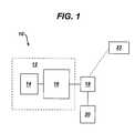
- an apparatus 10(illustrated in FIG. 1 ) is provided that can include an implantable shunt system 12 and a system controller 18 . While a variety of configurations are available, in one exemplary embodiment, the apparatus 10 can have an adjustable valve 14 for regulating the flow of fluid, a sensor element 20 for measuring a physiological characteristic of a patient, and an electromechanical valve actuator 16 that can be adapted to adjust a resistance of the valve.
- electromechanical actuatorincludes mechanical systems (or mechanisms) that are actuated or controlled electrically such as, but not limited to, electric motors, solenoids, and linear actuators.
- the implantable shunt systemcan be in electrical communication with the system controller 18 which may or may not be provided within the shunt system housing.
- the system controller 18can generally be adapted to receive a physiological characteristic of the patient from the sensor 20 and operate the electromechanical valve actuator 16 to adjust a resistance of the valve 14 .
- the system controller 18may also receive instructions from an external programming device 22 .
- the apparatuscan be battery powered (i.e., by a battery contained therein) or can be powered by an external component.
- CSFcerebrospinal fluid
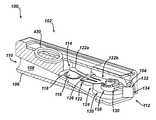
- FIG. 1Aillustrates one exemplary embodiment of an apparatus 100 for regulating fluid flow.
- the apparatuscan generally include an implantable shunt system 102 and a system controller 104 .
- the shunt system 102can be adapted to drain excess fluid from one area of a patient's body and direct the fluid to another site in the body.
- a variety of configurationsare available for the shunt system 102 .
- a shuntrefers to any device that diverts a flow of fluid.
- the shunt system 102includes a housing 106 defining an inlet port 110 , an outlet port 112 , and a chamber 108 oriented between the inlet port 110 and the outlet port 112 .
- the inlet and outlet ports 110 , 112can be coupled to inlet and outlet or drainage catheters 450 , respectively ( FIGS. 4-6 ).
- the apparatuscan be used to treat hydrocephalus and the inlet catheter is inserted within a ventricle of a patient's brain and the drainage catheter is inserted within another area of the patient's body, such as the peritoneum.
- the shunt system 102can carry CSF, originating from the ventricle, from the inlet catheter, through the chamber, and to the drainage catheter.
- the implantable shunt system 102can also include an adjustable valve 114 for regulating the flow of fluid.
- the resistance of the valve 114can be adjusted within the housing 106 to set a pressure threshold at which excess CSF begins to flow from the ventricle of a brain through the valve 114 and to another area of a patient's body.
- the valve 114can have several configurations, in an exemplary embodiment, shown in FIG. 1A , the valve 114 takes the form of a ball valve. As shown, the ball 116 is disposed in the chamber 108 of the housing 106 and is seated in a circular orifice 118 .
- valve 114is shown and described as a ball valve, one skilled in the art will appreciate that a number of valve configurations are available for use with the implantable shunt system 102 .
- the ball 116can act as a stop member and regulate the fluid flow through the shunt system 102 .
- fluidcan be prevented from flowing through the shunt system when the ball 116 is fully seated within the circular orifice 118 .
- fluidcan be allowed to flow through the shunt system 102 when the pressure in the ventricle exceeds the force being applied to the ball 116 to seat it in the circular orifice 118 .
- varying the force applied to the ball 116can be effective to vary the resistance of the valve 114 (i.e., the pressure threshold at which fluid begins to flow through the valve 114 ).
- an electromechanical valve actuator 120can be operatively associated with the valve 114 and adapted to adjust a resistance of the valve 114 .
- the electromechanical valve actuator 120can be configured to adjust and maintain the pressure threshold at which fluid begins to flow through the valve 114 thereby reducing the risk of either over- or under-drainage of CSF from a brain ventricle.
- the electromechanical valve actuator 120can generally include a spring 122 and a pressure setting mechanism 124 . The electromechanical valve actuator 120 can effectively prevent movement of the valve 114 , such as when the shunt system is exposed to environmental magnetic forces.
- the shunt system 102can be subjected to a strong external magnetic field, such as when a patient having an implanted shunt system 102 undergoes an magnetic resonance imaging (MRI) procedure.
- the magnetic fieldgenerates a force on the shunt system 102 that can induce motion of the pressure setting mechanism 124 and can cause the pressure setting mechanism 124 to adjust the position of the valve 114 .
- the electromechanical valve actuator 120can lock the valve 114 in place to maintain a set pressure threshold within the shunt system 102 when exposed to the magnetic field.
- FIGS. 1-3illustrate a variety of exemplary embodiments of electromechanical valve actuators 120 for use with the shunt system 102 described herein.
- various springs and configurations of pressure setting mechanismscan form the electromechanical valve actuator, and the actuator should not be limited to the features and configurations described below.
- the electromechanical valve actuator 120includes a leaf spring 122 that is coupled to a pressure setting mechanism 124 having a cantilever 126 and a rotor assembly 128 .
- the ball 116 of the ball valvecan regulate the fluid flow through the shunt system.
- the ball 116can be operatively joined to a first end 122 a of the cantilevered spring 122 which a second end 122 b of the spring 122 can engage a stair array 130 of the rotor assembly 128 .
- the rotor assembly 128can include the stair-step array 130 in the form of a spiral staircase to provide pressure settings in discrete steps.
- the rotor assembly 128can also include an actuation mechanism 132 that is configured to rotate the stair array 130 with respect to the cantilevered spring 122 .
- the mechanism 132can include a motor 134 that is operatively associated with the stair array 130 .
- the mechanism 132includes a micro-motor 134 that is coupled to the stair array 130 via gear teeth provided on each (not shown).
- a variety of motorscan be used to rotate the stair array 130 including, but not limited to, micro-motors, stepper-motors, and piezo-motors.
- the actuation mechanism 132 of electromechanical valve actuator 120can rotate the spiral stair array 130 with respect to the cantilevered spring 122 , and the second end 122 b of the spring 122 can move up or down each stair of the array 130 .
- Moving the second end 122 b of the spring 122 up or downcan be effective to change the angle of deflection of the spring 122 (e.g., relative to the cantilever 126 ).
- the change in the angle of deflection of the spring 122in turn, alters the force that is exerted by the spring 122 on the ball 116 .
- changing the force applied to the ball 116can result in a corresponding increase or decrease of the established pressure threshold at which fluid begins to flow through the shunt system 102 .
- An antenna 430can also be provided to allow for non-invasive control of the electromechanical valve actuator 120 .
- one or more antennas 430can have a variety of configurations as well as be disposed at various locations throughout the system.
- the shunt system 12 , system controller 18 , and programming device 22can include signal transmitters/receivers or antennas 430 that can be configured to send and/or receive signals from one another to allow the individual components of the apparatus 10 to communicate with each other as well as facilitate non-invasive control of the apparatus 10 .
- FIG. 2illustrates another exemplary embodiment of an electromechanical valve actuator 200 for use with the implantable shunt system 102 .
- the electromechanical valve actuator 200includes a leaf spring 202 that is operatively associated with a pressure setting mechanism 204 that takes the form of a gear assembly 206 .
- a first end 202 a of the leaf spring 202can be operatively associated with the ball 116 of the ball valve and a second end 202 b of the spring 202 can engage the gear assembly 206 .
- the gear assembly 206can include first and second gears 206 a , 206 b .
- the first gear 206 acan have a series of helical steps (not shown) formed thereon and can be adapted to engage the spring 202 .
- the second gear 206 bcan engage the first gear 206 a as well as be operatively associated with an actuation mechanism 208 of the gear assembly 206 .
- the actuation mechanism 208can be configured to drive the gears 206 a , 206 b and rotate the helical steps with respect to the spring 202 .
- the mechanism 208 shown in FIG. 2includes a micro-motor 210 that is coupled to the second gear 206 b via a cylindrical motor shaft 212 .
- a variety of motorscan be used to rotate the stair array including, but not limited to, micro-motors, stepper-motors, and piezo-motors.
- the actuation mechanism 208can drive the gear assembly 206 to rotate the helical steps with respect to the spring 202 and move the second end 202 b of the spring 202 up or down the steps. As described above, such movement can be effective to change in the angle of deflection of the spring 202 thereby altering the force that is exerted on the ball 116 and increasing or decreasing the established pressure threshold at which fluid begins to flow through the shunt system.
- the electromechanical valve actuator 300includes a helical spring 302 that is coupled to a pressure setting mechanism 304 having a stop member 306 and motor assembly 308 .
- a first end 302 a of the helical spring 302can engage the ball 116 of the ball valve, and a second end 302 b of the spring 302 can abut a distal facing surface 307 of the stop member 306 .
- the stop member 306can have virtually any configuration, for example, as shown in FIG. 3 , the stop member 306 is a generally cylindrical cap that has a closed distal end 306 b and an open proximal end 306 a with a bore 309 formed therein.
- the bore 309can be threaded and adapted to receive and engage a threaded shaft 308 a of the motor assembly 308 .
- a motor 308 bsuch as one described above, can drive the threaded shaft 308 a to move the stop member 306 in the proximal and/or distal directions.
- the closed distal end 306 b of the stop member 306can be configured to apply a force to the spring 302 such that distal movement of the stop member 306 is effective to compress the spring 302 and alter the force that is exerted by the spring 302 on the ball 116 .
- changing the force applied to the ball 116can result in a corresponding increase or decrease of the established pressure threshold at which fluid begins to flow through the shunt system.
- the implantable shunt systemcan further include a sensor element for measuring a physiological characteristic of a patient.
- the sensor elementcan be coupled to the valve or it can be separate from the valve.
- the sensor element 402is in electrical communication with the shunt system 401 and is coupled to the system via wires 402 a .
- the sensor element 402is shown as being positioned within the CSF flow pathway 406 of the shunt system 401 , in another exemplary embodiment, the sensor element 402 can be located outside of the CSF flow pathway 406 though still residing within the ventricular cavity of the patient.
- the sensor element 402can be configured to measure a variety of physiological characteristics of a patient including, but not limited to, CSF pressure.
- the shunt system 401is shown as having a single sensor element 402 , one skilled in the art will appreciate that the system can include multiple sensor elements having several different configurations.
- the system 401can include multiple pressure sensors to measure the CSF pressure at various points in the ventricular cavity.
- the system 401can include multiple sensor elements each configured to measure a different physiological characteristic of a patient.
- the apparatus 400 for regulating fluid flowcan also include a system controller 408 .
- the controller 408can be in electrical communication with the implantable shunt system 401 and can be adapted to receive the physiological characteristic measured by the sensor element 402 and to operate the electromechanical valve actuator 410 to adjust a resistance of the valve 114 .
- the system controller 408can be configured to receive an input signal that is generated by the sensor element 402 and is representative of the measured value of the physiological characteristic (e.g., the CSF pressure).
- the system controller 408can also be configured to generate and transmit to the electromechanical valve actuator 410 an output control signal that commands the actuator 410 to adjust the resistance of the valve 114 .
- a variety of configurationsare available for the system controller 408 .
- the controller 408is contained within the implantable shunt system 401 .
- the controller 408can be disposed on an implant 412 that is separate from the implantable shunt system 401 ( FIG. 6 ).
- the system controller 408can also include a processing unit such as, for example, a microprocessor, which enables the controller 408 to compare the measured physiological characteristic (e.g., the measured CSF pressure) detected by the sensor element 402 to a predetermined target value for the physiological characteristic.
- the predetermined target valuecan be ascertained through clinical assessment of the patent and is therefore customized for each particular patient. This target value can then be preset or programmed into the system controller 408 .
- the system controller 408can operate according to an algorithm which determines whether the value measured by the sensor element 402 is higher than, lower than, or within an acceptable range of the target value.
- the algorithmcan then determine whether the resistance of the valve 114 should be increased, decreased, or maintained in order to achieve the target CSF pressure for the patient. For example, where the physiological characteristic being measured is CSF pressure, the valve's resistance can be decreased if the measured pressure is higher than the target pressure. Conversely, the resistance of the valve 114 can be increased if the measured pressure is lower than the target pressure.
- the microprocessorcan then generate an output control signal to the electromechanical valve actuator 410 which commands the actuator 410 to adjust its current resistance to the desired resistance. If the measured value is essentially the same as, or within an acceptable range of the target value, then the current resistance is maintained and no changes are made.
- the apparatus 400 for regulating fluid flowcan further include an external programming device 420 that is in communication with the system controller 408 .
- the programming device 420can include a user input element that allows an operator to input one or more instructions to be communicated to the system controller 408 .
- the external programming device 420can be adapted to transmit a signal to the system controller 408 that is representative of a predetermined target value for the CSF pressure of a patient.
- the external programming device 420can have a variety configurations and in one exemplary embodiment can take the form of a hand-held remote control.
- the programming device 420can include a display for communicating input and/or output values (e.g., the predetermined target value for a physiological characteristic being measured and/or the measured value of a physiological characteristic) to a user.
- input and/or output valuese.g., the predetermined target value for a physiological characteristic being measured and/or the measured value of a physiological characteristic
- the programming device 420can also be adapted to power the implantable shunt system 401 .
- one or more antennas 430can be provided to allow the individual components of the apparatus 400 to communicate with each other as well as facilitate non-invasive control of the apparatus 400 .
- the implantable shunt system 401 , system controller 408 , and external programming device 420can be equipped with electronic circuitry similar to those for medical telemetry systems that communicate physiological data (e.g., temperature, pressure, etc.) between an implant and a receiver unit.
- the system controller 408can be configured to generate an analog data signal that is then converted electronically to a digital pulse which is then transmitted by radiofrequency (RF) to the external programming device 420 .
- RFradiofrequency
- the shunt system 401 , system controller 408 , and programming device 420include signal transmitters/receivers or antennas 430 that can be configured to send and/or receive signals from one another. Such communication can provide non-invasive control of the electromechanical valve actuator 410 .
- the antennas 430can have a variety of configurations as well as be disposed at various locations in the system. For example, in one exemplary embodiment shown in FIG. 4 , both the system controller 408 and antenna 430 associated therewith are disposed on the implantable shunt system 401 . In another embodiment, shown in FIG. 5 , the controller 408 is contained within the implantable shunt system 401 but the antenna 430 is disposed on a separate implant 430 a .
- both the system controller 408 and antenna 430 associated therewithare disposed on an implant 412 separate from the implantable shunt system 401 . Similar to the embodiment shown in FIG. 5 , this embodiment can provide less restriction on the size of the system controller 408 and antenna 430 , as these components are not part of the shunt system 401 .
- theseare merely examples of the forms of remote communication suitable for use with the fluid regulating apparatus 400 disclosed herein and a variety of other forms of non-invasive communication can be utilized without departing from the scope of the present invention.
- the methodcan include comparing a target value to a value detected by a sensor 402 associated with an implantable shunt system 401 , and activating an electromechanical valve actuator 410 of the implantable shunt system 401 to adjust a resistance of a valve 114 of the shunt system 401 if the detected value is not equal to the target value.
- the methodcan include energizing the apparatus 400 with the external programming device 420 and detecting a physiological characteristic of a ventricular cavity (e.g., CSF pressure).
- the measured valuecan then be compared to a predetermined target value for that physiological characteristic.
- the predetermined target valuecan be preset in the system controller 408 or can be programmed in the controller via the external programming device 420 . If the system controller 408 determines that the measured value is not equal to the target value, the controller 408 than determines whether the resistance for the valve 114 should be increased or deceased accordingly to achieve the predetermined target value for that physiological characteristic.
- the system controller 408can then generate and transmit an activation signal to activate the electromechanical valve actuator 410 and adjust a resistance of the valve 114 . If the measured value is essentially the same as, or within an acceptable range of the target value, then no change is made to the resistance of the valve 114 .
- datacan be communicated between the device 420 and the system controller 408 .
- a usercan input a target value to the programming device 420 and the device can communicate data representative of the target value to the system controller 408 .
- Datacan also be communicated between the implantable shunt system 401 and the system controller 408 .
- the sensor element 402can communicate data representative of the measured value of a physiological characteristic to the system controller 408 , and the controller 408 can communicate a command to the electromechanical valve actuator 410 to adjust a resistance of the valve 114 .
- the system controller 408can detect a value of a physiological characteristic measured by the sensor element 402 by receiving an input signal generated from the sensor element 402 that contains data about the measured value of the physiological characteristic. Similarly, the system controller 408 can adjust a resistance of the valve 114 by generating and transmitting an output control signal to the electromechanical valve actuator 410 that commands the actuator 410 to adjust a resistance of the valve 114 .
- the apparatus 401can be energized and data can be communicated from the external programming device 420 to the system controller 408 .
- the apparatus 401can be energized by either the patient himself or his attending physician. If the measured value is the same as, or falls within an acceptable range of the target value, then the system controller 408 is programmed to make no changes to the resistance. If, however, the system controller 408 detects that the measured value is higher or lower than the preset target value, the controller 408 sends a command to the electromechanical valve actuator 410 to adjust a resistance of the valve 114 .
- the apparatus 401can again be energized to measure the current value. If the system controller 408 does not detect a change in the measured value from the previous reading, the controller 408 can send another command to the electromechanical valve actuator 410 to adjust the resistance accordingly.
- the above stepscan be repeated until an appropriate resistance is attained and the system controller 408 detects that the measured value is approaching or has approached the target value for that patient. For example, the above steps can be repeated whenever the patient begins to experience pain or discomfort. However, to safeguard against repeated or excessive valve 114 adjustments within a short window of time, which could produce deleterious health consequences for the patient, the system controller 408 can include a timed shutoff mechanism which would limit the user's ability to adjust the valve in a given time period.
- the system controller's 408 valve adjustment featurescan be configured to deactivate after each use until a preset amount of time (e.g., a day, two days, a week, etc.) has passed whereby the valve adjustment feature is automatically reactivated.
- a preset amount of timee.g., a day, two days, a week, etc.
- the system controller 408can still be capable of detecting a physiological characteristic of the patient's ventricular cavity even when the device's valve adjustment features are not active. Hence, the patient can continue to monitor a physiological characteristic of his ventricular cavity using the apparatus 401 even between stages of adjusting the valve 114 .
Landscapes
- Health & Medical Sciences (AREA)
- Engineering & Computer Science (AREA)
- Biomedical Technology (AREA)
- Hematology (AREA)
- Ophthalmology & Optometry (AREA)
- Otolaryngology (AREA)
- Anesthesiology (AREA)
- Heart & Thoracic Surgery (AREA)
- Life Sciences & Earth Sciences (AREA)
- Animal Behavior & Ethology (AREA)
- General Health & Medical Sciences (AREA)
- Public Health (AREA)
- Veterinary Medicine (AREA)
- Neurology (AREA)
- Urology & Nephrology (AREA)
- External Artificial Organs (AREA)
Abstract
Description
Claims (33)
Priority Applications (8)
| Application Number | Priority Date | Filing Date | Title |
|---|---|---|---|
| US11/771,015US8123714B2 (en) | 2007-06-29 | 2007-06-29 | Programmable shunt with electromechanical valve actuator |
| AU2008202818AAU2008202818B2 (en) | 2007-06-29 | 2008-06-25 | Programmable shunt with electromechanical valve actuator |
| JP2008168241AJP5931313B2 (en) | 2007-06-29 | 2008-06-27 | Programmable shunt with electromechanical valve actuator |
| CA2636529ACA2636529C (en) | 2007-06-29 | 2008-06-27 | Programmable shunt with electromechanical valve actuator |
| CN2008102103327ACN101342402B (en) | 2007-06-29 | 2008-06-27 | Programmable shunt with electromechanical valve actuator |
| EP08252236AEP2008683A1 (en) | 2007-06-29 | 2008-06-30 | Programmable shunt with electromechanical valve actuator |
| CO08067110ACO6000189A1 (en) | 2007-06-29 | 2008-07-01 | PROGRAMMABLE DERIVER WITH ELECTROMECHANICAL VALVE ACTUATOR |
| US13/284,272US9925360B2 (en) | 2007-06-29 | 2011-10-28 | Programmable shunt with electromechanical valve actuator |
Applications Claiming Priority (1)
| Application Number | Priority Date | Filing Date | Title |
|---|---|---|---|
| US11/771,015US8123714B2 (en) | 2007-06-29 | 2007-06-29 | Programmable shunt with electromechanical valve actuator |
Related Child Applications (1)
| Application Number | Title | Priority Date | Filing Date |
|---|---|---|---|
| US13/284,272ContinuationUS9925360B2 (en) | 2007-06-29 | 2011-10-28 | Programmable shunt with electromechanical valve actuator |
Publications (2)
| Publication Number | Publication Date |
|---|---|
| US20090005720A1 US20090005720A1 (en) | 2009-01-01 |
| US8123714B2true US8123714B2 (en) | 2012-02-28 |
Family
ID=39717816
Family Applications (2)
| Application Number | Title | Priority Date | Filing Date |
|---|---|---|---|
| US11/771,015Active2029-04-08US8123714B2 (en) | 2007-06-29 | 2007-06-29 | Programmable shunt with electromechanical valve actuator |
| US13/284,272Active2028-12-22US9925360B2 (en) | 2007-06-29 | 2011-10-28 | Programmable shunt with electromechanical valve actuator |
Family Applications After (1)
| Application Number | Title | Priority Date | Filing Date |
|---|---|---|---|
| US13/284,272Active2028-12-22US9925360B2 (en) | 2007-06-29 | 2011-10-28 | Programmable shunt with electromechanical valve actuator |
Country Status (7)
| Country | Link |
|---|---|
| US (2) | US8123714B2 (en) |
| EP (1) | EP2008683A1 (en) |
| JP (1) | JP5931313B2 (en) |
| CN (1) | CN101342402B (en) |
| AU (1) | AU2008202818B2 (en) |
| CA (1) | CA2636529C (en) |
| CO (1) | CO6000189A1 (en) |
Cited By (16)
| Publication number | Priority date | Publication date | Assignee | Title |
|---|---|---|---|---|
| US20110071457A1 (en)* | 2009-09-15 | 2011-03-24 | Northwestern University | Method and apparatus for controlling intracranial pressure |
| US20110112460A1 (en)* | 2009-11-09 | 2011-05-12 | Medtronic Xomed, Inc. | Adjustable valve setting with motor control |
| US20110282264A1 (en)* | 2002-03-26 | 2011-11-17 | Medtronic Ps Medical, Inc. | Method of draining cerebrospinal fluid |
| US20120046595A1 (en)* | 2010-08-17 | 2012-02-23 | Codman & Shurtleff, Inc. | Implantable adjustable valve |
| WO2014092866A1 (en)* | 2012-12-10 | 2014-06-19 | Alcon Research, Ltd. | Suprachoriodal drainage tube in a flow control system |
| US20140276340A1 (en)* | 2013-03-12 | 2014-09-18 | DePuy Synthes Products, LLC | System and method for determining position and pressure of an implantable shunt |
| US9126010B2 (en) | 2013-03-14 | 2015-09-08 | Medtronic Xomed, Inc. | Device and method for finding the center and reading the setting of an implantable medical device |
| US9149615B2 (en) | 2010-08-17 | 2015-10-06 | DePuy Synthes Products, Inc. | Method and tools for implanted device |
| US9295826B2 (en) | 2012-06-21 | 2016-03-29 | Medtronic Xomed, Inc. | Fluid flow control devices, rotors and magnets with increased resistance to inadvertent setting change and improved accessory tool coupling |
| US9649481B2 (en) | 2013-03-14 | 2017-05-16 | Siddharth Sadanand | Shunt flow monitor |
| US9662478B2 (en) | 2010-03-19 | 2017-05-30 | University Of Washington | Body fluid drainage system |
| US9925360B2 (en) | 2007-06-29 | 2018-03-27 | Integra Lifesciences Switzerland Sàrl | Programmable shunt with electromechanical valve actuator |
| US10413710B2 (en) | 2014-01-16 | 2019-09-17 | University Of Washington | Pressure reference assemblies for body fluid drainage systems and associated methods |
| US10512762B2 (en) | 2011-01-27 | 2019-12-24 | Medtronic Xomed, Inc. | Adjustment for hydrocephalus shunt valve |
| US20210069486A1 (en)* | 2016-08-12 | 2021-03-11 | Carlos A. Hakim | Externally programable magnetic valve assembly and controller |
| US12420075B2 (en) | 2016-08-12 | 2025-09-23 | Ceredyn Biotechnology Llc | Externally programable magnetic valve assembly and controller |
Families Citing this family (30)
| Publication number | Priority date | Publication date | Assignee | Title |
|---|---|---|---|---|
| US8992456B1 (en)* | 2009-02-17 | 2015-03-31 | N. Garrett Powell | Implantable pump for removal of cerebrospinal fluid |
| US8679048B2 (en)* | 2009-03-31 | 2014-03-25 | Likvor Ab | Optimization of hydrocephalus shunt settings |
| US8109899B2 (en) | 2009-07-06 | 2012-02-07 | Likvor Ab | Fully automated method of measuring and regulating cerebrospinal fluid parameters using disposable tube-set |
| DE102009060533B4 (en)* | 2009-12-23 | 2019-07-11 | Christoph Miethke Gmbh & Co Kg | Implantable shunt system |
| US8231563B2 (en)* | 2009-12-30 | 2012-07-31 | Codman Neuro Sciences Sarl | Electrokinetic actuator to titrate fluid flow |
| US20120302938A1 (en)* | 2010-03-19 | 2012-11-29 | University Of Washington | Drainage systems for excess body fluids and associated methods |
| DE102010051743B4 (en) | 2010-11-19 | 2022-09-01 | C. Miethke Gmbh & Co. Kg | Programmable hydrocephalus valve |
| CA2828427A1 (en) | 2011-03-11 | 2012-09-20 | Chris ARNOTT | Systems and methods of controlling flow of bodily fluids |
| US20130201316A1 (en) | 2012-01-09 | 2013-08-08 | May Patents Ltd. | System and method for server based control |
| US20130226066A1 (en)* | 2012-02-23 | 2013-08-29 | Jung-Tung Liu | Apparatus for monitoring cerebrospinal fluid drainage |
| CN103504025A (en)* | 2012-06-25 | 2014-01-15 | 浙江康恩贝健康产品有限公司 | Wet preparation process of infant formula milk powder |
| US10322267B2 (en) | 2013-03-15 | 2019-06-18 | Carlos A. Hakim | Externally programmable valve assembly |
| FR3010636B1 (en) | 2013-09-16 | 2015-10-02 | Sophysa Sa | ADJUSTABLE DRAINAGE VALVE |
| US9656006B2 (en)* | 2013-10-18 | 2017-05-23 | InfinivationBiomedical, LLC | Wearable external ventricular drain system |
| CN107281562B (en)* | 2017-06-12 | 2023-07-21 | 郑春玲 | Adjusting device in cerebrospinal fluid drainage system and cerebrospinal fluid drainage system |
| CN108331793B (en)* | 2018-02-07 | 2020-06-26 | 安徽工程大学 | A Hydraulic Diversion System with Circuit Controlling Pressure Proportion |
| CN108331794B (en)* | 2018-02-09 | 2020-06-26 | 安徽工程大学 | Hydraulic pressure reposition of redundant personnel system of arbitrary distribution pressure proportion |
| US20210379344A1 (en)* | 2018-10-26 | 2021-12-09 | Hakim Carlos | Self-adjusting hydrocephalus valve |
| US11103683B1 (en)* | 2020-02-10 | 2021-08-31 | Frederick H. Sklar | Implantable intracranial pulse pressure modulator and system and method for use of same |
| AU2021202952A1 (en)* | 2020-05-21 | 2021-12-09 | Carlos A. Hakim | Externally programable magnetic valve assembly and controller |
| US12059542B2 (en) | 2020-07-31 | 2024-08-13 | Medtronic Ps Medical, Inc. | System and method for valve control |
| US11701503B2 (en)* | 2020-07-31 | 2023-07-18 | Medtronic Ps Medical, Inc. | System and method for valve control |
| CN113323928B (en)* | 2021-05-24 | 2022-08-12 | 安徽工程大学 | A proportionally controllable and pressure-boosting hydraulic diverter system |
| WO2023009133A1 (en)* | 2021-07-30 | 2023-02-02 | Medtronic Ps Medical, Inc. | System for valve control |
| WO2023039541A1 (en)* | 2021-09-09 | 2023-03-16 | Wayne State University | Solid state shunt valve with active outflow regulator, ventricular catheters, and other embodiments |
| EP4442191A4 (en)* | 2021-12-03 | 2025-09-03 | Seoul Nat Univ Hospital | Method and device for monitoring cerebrospinal fluid based on near-infrared spectroscopy |
| US20230355937A1 (en)* | 2022-05-05 | 2023-11-09 | Samuel Robert Browd | Dynamically Controlled Cerebrospinal Fluid Shunt |
| US12082981B2 (en) | 2022-11-07 | 2024-09-10 | Frederick H. Sklar | Surgical armrest |
| US12083052B2 (en) | 2022-11-07 | 2024-09-10 | Frederick H. Sklar | Surgical universal headrest including skull pin holder assembly |
| US12345373B2 (en) | 2022-11-07 | 2025-07-01 | Frederick H. Sklar | Base station assembly for an operating room table |
Citations (28)
| Publication number | Priority date | Publication date | Assignee | Title |
|---|---|---|---|---|
| US3886948A (en)* | 1972-08-14 | 1975-06-03 | Hakim Co Ltd | Ventricular shunt having a variable pressure valve |
| US4332255A (en) | 1979-01-10 | 1982-06-01 | Hakim Company Limited | Shunt valve |
| US4387715A (en) | 1980-09-23 | 1983-06-14 | Hakim Company Limited | Shunt valve |
| US4443214A (en) | 1981-03-18 | 1984-04-17 | Society Dite: Sophysa | Valve for the treatment of hydrocephalus |
| US4551128A (en) | 1983-05-11 | 1985-11-05 | Salomon Hakim | Cerebrospinal fluid shunt valve |
| US4595390A (en) | 1983-07-21 | 1986-06-17 | Salomon Hakim | Magnetically-adjustable cerebrospinal fluid shunt valve |
| US4615691A (en) | 1983-12-08 | 1986-10-07 | Salomon Hakim | Surgically-implantable stepping motor |
| US4772257A (en) | 1983-12-08 | 1988-09-20 | Salomon Hakim | External programmer for magnetically-adjustable cerebrospinal fluid shunt valve |
| US5637083A (en) | 1996-01-19 | 1997-06-10 | Pudenz-Schulte Medical Research Corporation | Implantable adjustable fluid flow control valve |
| US5643194A (en) | 1994-06-24 | 1997-07-01 | Sophysa | Subcutaneous valve and device for externally setting it |
| US5704352A (en) | 1995-11-22 | 1998-01-06 | Tremblay; Gerald F. | Implantable passive bio-sensor |
| US5928182A (en) | 1997-07-02 | 1999-07-27 | Johnson & Johnson Professional, Inc. | Pediatric programmable hydrocephalus valve |
| EP0982048A1 (en) | 1998-03-12 | 2000-03-01 | Leonhardt, Steffen, Dr.-Ing. | Implant for controlled drainage of cerebrospinal fluid |
| US20010002250A1 (en) | 1998-03-03 | 2001-05-31 | Burbank Fred H. | Sentinel node location and biopsy |
| US6264625B1 (en)* | 1996-07-11 | 2001-07-24 | Cs Fluids, Inc. | Method and apparatus for treating adult-onset dementia of the Alzheimer's type |
| US6336924B1 (en)* | 1997-12-17 | 2002-01-08 | Nmt Neurosciences Implants S.A. | External biological fluid drainage device |
| US20020026139A1 (en) | 2000-02-02 | 2002-02-28 | Bertrand William Jeff | Valve seat and valve |
| US20020058901A1 (en) | 2000-11-13 | 2002-05-16 | Bernard Marion | Implantable subcutaneous value for the treatment of hydrocephalus, and adjusting devices therefor |
| WO2002047754A1 (en) | 2000-12-11 | 2002-06-20 | Christoph Miethke Gmbh & Co. Kg | Hydrocephalus valve |
| US6533733B1 (en)* | 1999-09-24 | 2003-03-18 | Ut-Battelle, Llc | Implantable device for in-vivo intracranial and cerebrospinal fluid pressure monitoring |
| US6585677B2 (en)* | 2000-08-30 | 2003-07-01 | John A. Cowan, Jr. | Shunt |
| US20040010219A1 (en) | 2002-07-10 | 2004-01-15 | Mccusker Daniel | Shunt valve locking mechanism |
| US6702249B2 (en) | 2001-03-19 | 2004-03-09 | Seiko Instruments Inc. | Pressure-variable valve device and set-pressure adjusting device for the valve device |
| US20040143242A1 (en) | 2003-01-22 | 2004-07-22 | Lev Ludin | Troubleshooting accelerator system for implantable drug delivery pumps |
| US20050010159A1 (en) | 2002-01-04 | 2005-01-13 | Sanford Reich | Csf physiologic controller |
| US20050092335A1 (en) | 2003-10-31 | 2005-05-05 | Medtronic, Inc. | Electronic valve reader |
| US20060020239A1 (en) | 2004-07-20 | 2006-01-26 | Geiger Mark A | Cerebral spinal fluid flow sensing device |
| EP1738792A1 (en) | 2005-06-29 | 2007-01-03 | Codman & Shurtleff, Inc. | Apparatus and method for adjusting a locking mechanism of a shunt valve |
Family Cites Families (16)
| Publication number | Priority date | Publication date | Assignee | Title |
|---|---|---|---|---|
| US4447224A (en) | 1982-09-20 | 1984-05-08 | Infusaid Corporation | Variable flow implantable infusion apparatus |
| JPH0417708A (en) | 1990-05-07 | 1992-01-22 | Nissan Motor Co Ltd | Internal combustion engine lubrication hydraulic regulator |
| JP3489643B2 (en) | 1995-08-31 | 2004-01-26 | エイ.ビラファナ マニュエル | Telemetry device for information on operating characteristics of implanted prosthetic heart valves |
| WO2001039819A2 (en)* | 1999-12-03 | 2001-06-07 | Neuron Therapeutics, Inc. | Method and apparatus for closed recirculation of synthetic cerebrospinal fluid |
| JP2002022048A (en) | 2000-07-06 | 2002-01-23 | Seiko Instruments Inc | Pressure variable valve device |
| US6953444B2 (en)* | 2002-01-24 | 2005-10-11 | Codman & Shurtleff, Inc. | Inherent anti-siphon device |
| CN1186102C (en)* | 2002-06-20 | 2005-01-26 | 杨际芝 | Monitoring and therapeutic apparatus for draining and displacing cerebrospinal fluid and pressurizing |
| JP2004321296A (en)* | 2003-04-22 | 2004-11-18 | Japan Lifeline Co Ltd | Body fluid discharge control device and body fluid discharge control method |
| US8353857B2 (en) | 2003-06-23 | 2013-01-15 | Codman & Shurtleff, Inc. | Implantable medical device having pressure sensors for diagnosing the performance of an implanted medical device |
| US20050055009A1 (en)* | 2003-09-05 | 2005-03-10 | Codman & Shurtleff, Inc. | Method and apparatus for managing normal pressure hydrocephalus |
| US7599743B2 (en) | 2004-06-24 | 2009-10-06 | Ethicon Endo-Surgery, Inc. | Low frequency transcutaneous energy transfer to implanted medical device |
| JP4328680B2 (en) | 2004-07-01 | 2009-09-09 | 株式会社カネカメディックス | Subcutaneous implantable valve device |
| US20080097277A1 (en)* | 2005-02-22 | 2008-04-24 | Saunders Richard L | Controllable Shunt |
| CN1895694A (en)* | 2005-04-05 | 2007-01-17 | 科德曼及舒特莱夫公司 | Subarachnoid epidural shunt |
| JP4742723B2 (en) | 2005-07-27 | 2011-08-10 | 日本精工株式会社 | Toroidal continuously variable transmission and continuously variable transmission |
| US8123714B2 (en) | 2007-06-29 | 2012-02-28 | Codman & Shurtleff, Inc. | Programmable shunt with electromechanical valve actuator |
- 2007
- 2007-06-29USUS11/771,015patent/US8123714B2/enactiveActive
- 2008
- 2008-06-25AUAU2008202818Apatent/AU2008202818B2/enactiveActive
- 2008-06-27CACA2636529Apatent/CA2636529C/enactiveActive
- 2008-06-27CNCN2008102103327Apatent/CN101342402B/enactiveActive
- 2008-06-27JPJP2008168241Apatent/JP5931313B2/enactiveActive
- 2008-06-30EPEP08252236Apatent/EP2008683A1/ennot_activeWithdrawn
- 2008-07-01COCO08067110Apatent/CO6000189A1/enactiveIP Right Grant
- 2011
- 2011-10-28USUS13/284,272patent/US9925360B2/enactiveActive
Patent Citations (30)
| Publication number | Priority date | Publication date | Assignee | Title |
|---|---|---|---|---|
| US3886948A (en)* | 1972-08-14 | 1975-06-03 | Hakim Co Ltd | Ventricular shunt having a variable pressure valve |
| US4332255A (en) | 1979-01-10 | 1982-06-01 | Hakim Company Limited | Shunt valve |
| US4387715A (en) | 1980-09-23 | 1983-06-14 | Hakim Company Limited | Shunt valve |
| US4443214A (en) | 1981-03-18 | 1984-04-17 | Society Dite: Sophysa | Valve for the treatment of hydrocephalus |
| US4551128A (en) | 1983-05-11 | 1985-11-05 | Salomon Hakim | Cerebrospinal fluid shunt valve |
| US4595390A (en) | 1983-07-21 | 1986-06-17 | Salomon Hakim | Magnetically-adjustable cerebrospinal fluid shunt valve |
| US4615691A (en) | 1983-12-08 | 1986-10-07 | Salomon Hakim | Surgically-implantable stepping motor |
| US4772257A (en) | 1983-12-08 | 1988-09-20 | Salomon Hakim | External programmer for magnetically-adjustable cerebrospinal fluid shunt valve |
| US5643194A (en) | 1994-06-24 | 1997-07-01 | Sophysa | Subcutaneous valve and device for externally setting it |
| US5704352A (en) | 1995-11-22 | 1998-01-06 | Tremblay; Gerald F. | Implantable passive bio-sensor |
| US5637083A (en) | 1996-01-19 | 1997-06-10 | Pudenz-Schulte Medical Research Corporation | Implantable adjustable fluid flow control valve |
| US6264625B1 (en)* | 1996-07-11 | 2001-07-24 | Cs Fluids, Inc. | Method and apparatus for treating adult-onset dementia of the Alzheimer's type |
| US5928182A (en) | 1997-07-02 | 1999-07-27 | Johnson & Johnson Professional, Inc. | Pediatric programmable hydrocephalus valve |
| US6336924B1 (en)* | 1997-12-17 | 2002-01-08 | Nmt Neurosciences Implants S.A. | External biological fluid drainage device |
| US20010002250A1 (en) | 1998-03-03 | 2001-05-31 | Burbank Fred H. | Sentinel node location and biopsy |
| EP0982048A1 (en) | 1998-03-12 | 2000-03-01 | Leonhardt, Steffen, Dr.-Ing. | Implant for controlled drainage of cerebrospinal fluid |
| US6533733B1 (en)* | 1999-09-24 | 2003-03-18 | Ut-Battelle, Llc | Implantable device for in-vivo intracranial and cerebrospinal fluid pressure monitoring |
| US20020026139A1 (en) | 2000-02-02 | 2002-02-28 | Bertrand William Jeff | Valve seat and valve |
| US6585677B2 (en)* | 2000-08-30 | 2003-07-01 | John A. Cowan, Jr. | Shunt |
| US20020058901A1 (en) | 2000-11-13 | 2002-05-16 | Bernard Marion | Implantable subcutaneous value for the treatment of hydrocephalus, and adjusting devices therefor |
| US6840917B2 (en) | 2000-11-13 | 2005-01-11 | Bernard Marion | Implantable subcutaneous valve for the treatment of hydrocephalus, and adjusting devices therefor |
| WO2002047754A1 (en) | 2000-12-11 | 2002-06-20 | Christoph Miethke Gmbh & Co. Kg | Hydrocephalus valve |
| US6926691B2 (en)* | 2000-12-11 | 2005-08-09 | Christoph Miethke | Hydrocephalus valve |
| US6702249B2 (en) | 2001-03-19 | 2004-03-09 | Seiko Instruments Inc. | Pressure-variable valve device and set-pressure adjusting device for the valve device |
| US20050010159A1 (en) | 2002-01-04 | 2005-01-13 | Sanford Reich | Csf physiologic controller |
| US20040010219A1 (en) | 2002-07-10 | 2004-01-15 | Mccusker Daniel | Shunt valve locking mechanism |
| US20040143242A1 (en) | 2003-01-22 | 2004-07-22 | Lev Ludin | Troubleshooting accelerator system for implantable drug delivery pumps |
| US20050092335A1 (en) | 2003-10-31 | 2005-05-05 | Medtronic, Inc. | Electronic valve reader |
| US20060020239A1 (en) | 2004-07-20 | 2006-01-26 | Geiger Mark A | Cerebral spinal fluid flow sensing device |
| EP1738792A1 (en) | 2005-06-29 | 2007-01-03 | Codman & Shurtleff, Inc. | Apparatus and method for adjusting a locking mechanism of a shunt valve |
Non-Patent Citations (1)
| Title |
|---|
| Search Report for EP 06 25 3362, dated Sep. 18, 2006. |
Cited By (31)
| Publication number | Priority date | Publication date | Assignee | Title |
|---|---|---|---|---|
| US20110282264A1 (en)* | 2002-03-26 | 2011-11-17 | Medtronic Ps Medical, Inc. | Method of draining cerebrospinal fluid |
| US9694166B2 (en)* | 2002-03-26 | 2017-07-04 | Medtronics Ps Medical, Inc. | Method of draining cerebrospinal fluid |
| US9925360B2 (en) | 2007-06-29 | 2018-03-27 | Integra Lifesciences Switzerland Sàrl | Programmable shunt with electromechanical valve actuator |
| US20110071457A1 (en)* | 2009-09-15 | 2011-03-24 | Northwestern University | Method and apparatus for controlling intracranial pressure |
| US8753331B2 (en) | 2009-11-09 | 2014-06-17 | Medtronic Xomed, Inc. | Adjustable valve setting with motor control |
| US20110112460A1 (en)* | 2009-11-09 | 2011-05-12 | Medtronic Xomed, Inc. | Adjustable valve setting with motor control |
| US8241240B2 (en)* | 2009-11-09 | 2012-08-14 | Medtronic Xomed, Inc. | Adjustable valve setting with motor control |
| US10166375B2 (en) | 2010-03-19 | 2019-01-01 | University Of Washington | Body fluid drainage system |
| US11247030B2 (en) | 2010-03-19 | 2022-02-15 | University Of Washington | Body fluid drainage system |
| US9662478B2 (en) | 2010-03-19 | 2017-05-30 | University Of Washington | Body fluid drainage system |
| US10092734B2 (en) | 2010-08-17 | 2018-10-09 | Integra LifeSciences Switzerland Sarl | Method and tools for implanted device |
| US9149615B2 (en) | 2010-08-17 | 2015-10-06 | DePuy Synthes Products, Inc. | Method and tools for implanted device |
| US20120046595A1 (en)* | 2010-08-17 | 2012-02-23 | Codman & Shurtleff, Inc. | Implantable adjustable valve |
| US8617142B2 (en) | 2010-08-17 | 2013-12-31 | DePuy Synthes Products, LLC | Implantable adjustable valve |
| US8322365B2 (en)* | 2010-08-17 | 2012-12-04 | Codman & Shurtleff, Inc. | Implantable adjustable valve |
| US10512762B2 (en) | 2011-01-27 | 2019-12-24 | Medtronic Xomed, Inc. | Adjustment for hydrocephalus shunt valve |
| US11167117B2 (en) | 2012-06-21 | 2021-11-09 | Medtronic Xomed, Inc. | Fluid flow control devices, rotors and magnets with increased resistance to inadvertent setting change and improved accessory tool coupling |
| US9295826B2 (en) | 2012-06-21 | 2016-03-29 | Medtronic Xomed, Inc. | Fluid flow control devices, rotors and magnets with increased resistance to inadvertent setting change and improved accessory tool coupling |
| US10369335B2 (en) | 2012-06-21 | 2019-08-06 | Medtronic Xomed, Inc. | Fluid flow control devices, rotors and magnets with increased resistance to inadvertent setting change and improved accessory tool coupling |
| WO2014092866A1 (en)* | 2012-12-10 | 2014-06-19 | Alcon Research, Ltd. | Suprachoriodal drainage tube in a flow control system |
| US9808607B2 (en) | 2013-03-12 | 2017-11-07 | DePuy Synthes Products, Inc. | System and method for determining position and pressure of an implantable shunt |
| US9126009B2 (en)* | 2013-03-12 | 2015-09-08 | DePuy Synthes Products, Inc. | System and method for determining position and pressure of an implantable shunt |
| US20140276340A1 (en)* | 2013-03-12 | 2014-09-18 | DePuy Synthes Products, LLC | System and method for determining position and pressure of an implantable shunt |
| US9649481B2 (en) | 2013-03-14 | 2017-05-16 | Siddharth Sadanand | Shunt flow monitor |
| US9427559B2 (en) | 2013-03-14 | 2016-08-30 | Medtronic Xomed, Inc. | Device and method for finding the center and reading the setting of an implantable medical device |
| US10881841B2 (en) | 2013-03-14 | 2021-01-05 | Siddharth Sadanand | Shunt flow monitor |
| US9126010B2 (en) | 2013-03-14 | 2015-09-08 | Medtronic Xomed, Inc. | Device and method for finding the center and reading the setting of an implantable medical device |
| US10413710B2 (en) | 2014-01-16 | 2019-09-17 | University Of Washington | Pressure reference assemblies for body fluid drainage systems and associated methods |
| US20210069486A1 (en)* | 2016-08-12 | 2021-03-11 | Carlos A. Hakim | Externally programable magnetic valve assembly and controller |
| US12420075B2 (en) | 2016-08-12 | 2025-09-23 | Ceredyn Biotechnology Llc | Externally programable magnetic valve assembly and controller |
| US12434043B2 (en)* | 2016-08-12 | 2025-10-07 | Ceredyn Biotechnology Llc | Externally programable magnetic valve assembly and controller |
Also Published As
| Publication number | Publication date |
|---|---|
| AU2008202818B2 (en) | 2013-10-24 |
| JP2009028526A (en) | 2009-02-12 |
| US9925360B2 (en) | 2018-03-27 |
| CO6000189A1 (en) | 2009-01-30 |
| CA2636529C (en) | 2015-11-24 |
| US20120046596A1 (en) | 2012-02-23 |
| CN101342402A (en) | 2009-01-14 |
| CA2636529A1 (en) | 2008-12-29 |
| JP5931313B2 (en) | 2016-06-08 |
| AU2008202818A1 (en) | 2009-01-15 |
| CN101342402B (en) | 2013-03-27 |
| US20090005720A1 (en) | 2009-01-01 |
| EP2008683A1 (en) | 2008-12-31 |
Similar Documents
| Publication | Publication Date | Title |
|---|---|---|
| US8123714B2 (en) | Programmable shunt with electromechanical valve actuator | |
| US6383160B1 (en) | Variable anti-siphon valve apparatus and method | |
| JP5052745B2 (en) | Apparatus for regulating cerebrospinal fluid flow in hydrocephalus patients | |
| EP1491137B1 (en) | An implantable medical device having pressure sensors control | |
| US7025739B2 (en) | System and method for treating elevated intracranial pressure | |
| EP2366423B1 (en) | Electrokinetic actuator to titrate fluid flow | |
| US6926691B2 (en) | Hydrocephalus valve | |
| US7189221B2 (en) | Methods for the treatment of a normal pressure hydrocephalus | |
| CN113194824B (en) | Self-adjusting hydrocephalus valve | |
| US20130303971A1 (en) | Catheter and shunt system including the catheter | |
| EP1386634B1 (en) | Cerebrospinal fluid shunt system incorporating an adjustable resistance valve | |
| US8211051B2 (en) | Electroactive polymer actuated cerebrospinal fluid shunt | |
| US20080097277A1 (en) | Controllable Shunt | |
| AU2013242833B2 (en) | Programmable shunt with electromechanical valve actuator |
Legal Events
| Date | Code | Title | Description |
|---|---|---|---|
| AS | Assignment | Owner name:CODMAN & SHURTLEFF, INC., MASSACHUSETTS Free format text:ASSIGNMENT OF ASSIGNORS INTEREST;ASSIGNORS:LUDIN, LEV;MAUGE, CHRISTOPHER;REEL/FRAME:019839/0237 Effective date:20070914 | |
| STCF | Information on status: patent grant | Free format text:PATENTED CASE | |
| FPAY | Fee payment | Year of fee payment:4 | |
| AS | Assignment | Owner name:DEPUY SPINE, LLC, MASSACHUSETTS Free format text:ASSIGNMENT OF ASSIGNORS INTEREST;ASSIGNOR:CODMAN & SHURTLEFF, INC.;REEL/FRAME:045058/0627 Effective date:20121230 | |
| AS | Assignment | Owner name:HAND INNOVATIONS LLC, FLORIDA Free format text:ASSIGNMENT OF ASSIGNORS INTEREST;ASSIGNOR:DEPUY SPINE, LLC;REEL/FRAME:045074/0943 Effective date:20121230 Owner name:DEPUY SYNTHES PRODUCTS, LLC, MASSACHUSETTS Free format text:CHANGE OF NAME;ASSIGNOR:HAND INNOVATIONS LLC;REEL/FRAME:045476/0712 Effective date:20121231 Owner name:DEPUY SYNTHES PRODUCTS, INC., INDIANA Free format text:CHANGE OF NAME;ASSIGNOR:DEPUY SYNTHES PRODUCTS, LLC;REEL/FRAME:045479/0763 Effective date:20141219 | |
| AS | Assignment | Owner name:INTEGRA LIFESCIENCES SWITZERLAND SARL, SWITZERLAND Free format text:ASSIGNMENT OF ASSIGNORS INTEREST;ASSIGNOR:DEPUY SYNTHES PRODUCTS, INC.;REEL/FRAME:045569/0299 Effective date:20171002 | |
| MAFP | Maintenance fee payment | Free format text:PAYMENT OF MAINTENANCE FEE, 8TH YEAR, LARGE ENTITY (ORIGINAL EVENT CODE: M1552); ENTITY STATUS OF PATENT OWNER: LARGE ENTITY Year of fee payment:8 | |
| MAFP | Maintenance fee payment | Free format text:PAYMENT OF MAINTENANCE FEE, 12TH YEAR, LARGE ENTITY (ORIGINAL EVENT CODE: M1553); ENTITY STATUS OF PATENT OWNER: LARGE ENTITY Year of fee payment:12 |