US8123502B2 - Acoustic pump utilizing radial pressure oscillations - Google Patents
Acoustic pump utilizing radial pressure oscillationsDownload PDFInfo
- Publication number
- US8123502B2 US8123502B2US11/918,796US91879606AUS8123502B2US 8123502 B2US8123502 B2US 8123502B2US 91879606 AUS91879606 AUS 91879606AUS 8123502 B2US8123502 B2US 8123502B2
- Authority
- US
- United States
- Prior art keywords
- cavity
- end walls
- pump
- pump according
- walls
- Prior art date
- Legal status (The legal status is an assumption and is not a legal conclusion. Google has not performed a legal analysis and makes no representation as to the accuracy of the status listed.)
- Active, expires
Links
- 230000010355oscillationEffects0.000titleclaimsabstractdescription28
- 239000012530fluidSubstances0.000claimsabstractdescription23
- 230000033001locomotionEffects0.000claimsabstractdescription21
- 230000003534oscillatory effectEffects0.000claimsabstractdescription9
- 238000006073displacement reactionMethods0.000claimsdescription12
- 238000005086pumpingMethods0.000description5
- 230000003321amplificationEffects0.000description4
- 238000003199nucleic acid amplification methodMethods0.000description4
- 230000006870functionEffects0.000description3
- 230000007246mechanismEffects0.000description3
- 229910000831SteelInorganic materials0.000description2
- 239000010959steelSubstances0.000description2
- 239000000725suspensionSubstances0.000description2
- 230000001133accelerationEffects0.000description1
- 238000006243chemical reactionMethods0.000description1
- 230000006835compressionEffects0.000description1
- 238000007906compressionMethods0.000description1
- 238000011161developmentMethods0.000description1
- 230000018109developmental processEffects0.000description1
- 230000000694effectsEffects0.000description1
- 239000007788liquidSubstances0.000description1
- 230000021715photosynthesis, light harvestingEffects0.000description1
- 238000000926separation methodMethods0.000description1
- 239000007787solidSubstances0.000description1
Images


Classifications
- F—MECHANICAL ENGINEERING; LIGHTING; HEATING; WEAPONS; BLASTING
- F04—POSITIVE - DISPLACEMENT MACHINES FOR LIQUIDS; PUMPS FOR LIQUIDS OR ELASTIC FLUIDS
- F04B—POSITIVE-DISPLACEMENT MACHINES FOR LIQUIDS; PUMPS
- F04B43/00—Machines, pumps, or pumping installations having flexible working members
- F04B43/02—Machines, pumps, or pumping installations having flexible working members having plate-like flexible members, e.g. diaphragms
- F04B43/04—Pumps having electric drive
- F04B43/043—Micropumps
- F04B43/046—Micropumps with piezoelectric drive
- F—MECHANICAL ENGINEERING; LIGHTING; HEATING; WEAPONS; BLASTING
- F04—POSITIVE - DISPLACEMENT MACHINES FOR LIQUIDS; PUMPS FOR LIQUIDS OR ELASTIC FLUIDS
- F04B—POSITIVE-DISPLACEMENT MACHINES FOR LIQUIDS; PUMPS
- F04B45/00—Pumps or pumping installations having flexible working members and specially adapted for elastic fluids
- F04B45/04—Pumps or pumping installations having flexible working members and specially adapted for elastic fluids having plate-like flexible members, e.g. diaphragms
- F04B45/047—Pumps having electric drive
- F—MECHANICAL ENGINEERING; LIGHTING; HEATING; WEAPONS; BLASTING
- F04—POSITIVE - DISPLACEMENT MACHINES FOR LIQUIDS; PUMPS FOR LIQUIDS OR ELASTIC FLUIDS
- F04F—PUMPING OF FLUID BY DIRECT CONTACT OF ANOTHER FLUID OR BY USING INERTIA OF FLUID TO BE PUMPED; SIPHONS
- F04F7/00—Pumps displacing fluids by using inertia thereof, e.g. by generating vibrations therein
Definitions
- This inventionrelates to a pump for a fluid and, in particular, to a pump in which the pumping cavity is substantially cylindrical in shape, but is sized such that the aspect ratio is large, i.e. the cavity is disk-shaped.
- thermoacousticsThe generation of high amplitude pressure oscillations in closed cavities has received significant attention in the fields of thermoacoustics and pump/compressors. Recent developments in non-linear acoustics have allowed the generation of pressure waves with higher amplitudes than previously thought possible.
- acoustic resonanceit is known to use acoustic resonance to achieve fluid pumping from defined inlets and outlets. This can be achieved using a cylindrical cavity with an acoustic driver at one end, which drives an acoustic standing wave. In such a cylindrical cavity, the acoustic pressure wave has limited amplitude. Varying cross-section cavities, such as cone, horn-cone, bulb have been used to achieve high amplitude pressure oscillations thereby significantly increasing the pumping effect. In such high amplitude waves the non-linear mechanisms with energy dissipation have been suppressed. However, high amplitude acoustic resonance has not been employed within disk-shaped cavities in which radial pressure oscillations are excited.
- a linear resonance compressoris also known in which the mass of the drive armature and spring force of a steel diaphragm combine to provide a mechanically resonant drive to the air cavity.
- This driveis coupled to a cylindrical cavity of diameter between 4 and 15 cm (depending on the design of the compressor) through a steel diaphragm, which is capable of up to 1.5 mm displacement in use.
- the drive frequencyis set to between 150 and 300 Hz by the mechanical resonance. At this frequency, the radial acoustic wavelength is much longer than the cavity radius. Therefore it can be deduced that radial pressure oscillations are not employed in this cavity pump.
- the low frequency drive mechanism used in this linear resonance compressorincorporates an electromechanical armature, leaf spring suspension, noise enclosure, and vibration mount suspension. This leads to a large overall size of the compressor.
- the present inventionaims to overcome one or more of the above identified problems.
- a fluid pumpcomprising:
- a cavity which, in use, contains fluidthe cavity having a substantially cylindrical shape bounded by the end walls and the side walls;
- h> 1.2 ; and h 2 a > 4 ⁇ 10 - 10 ⁇ ⁇ m ;
- the actuatorcauses oscillatory motion of one or both end walls in a direction substantially perpendicular to the plane of the end walls;
- h 2 ashould be greater than 4 ⁇ 10 ⁇ 10 m when pumping a liquid, but in the case of pumping a gas, it is preferable that the ratio is greater than 1 ⁇ 10 ⁇ 7 m.
- the present inventionprovides a substantially disk-shaped cavity having a high aspect ratio.
- the inventioncan be thought of as an acoustic pump, in that an acoustic resonance is set up within the cavity.
- the driver velocitytypically of the order of 1 ms ⁇ 1
- the geometry of the cavityto give an effective drive velocity far exceeding this value, producing a very high acoustic pressure.
- the high pressuremay be seen as arising from the inertial reaction of the air (the air's resistance to motion) to the high acceleration imposed upon it by the combination of the actuator movement and the cavity geometry.
- the present inventionovercomes the large size of known linear resonance compressors by replacing the low frequency drive mechanism with a disk actuator, preferably piezoelectric.
- This diskis typically less than 1 mm thick and is tuned to operate at more than 500 Hz, preferably 10 kHz, more preferably 20 kHz or higher.
- a frequency of approximately 20 kHz or aboveprovides operation above the threshold of normal human hearing, thereby removing the need for a noise enclosure.
- the frequency of the oscillatory motionis within 20% of the lowest resonant frequency of radial pressure oscillations in the cavity. More preferably, the frequency of the oscillatory motion is, in use, equal to the lowest resonant frequency of radial pressure oscillations in the cavity.
- the high frequency of the present inventionsignificantly reduces the size of the cavity and the overall device. Accordingly, the present invention can be constructed with a cavity volume of less than 10 ml, making it ideally suited to micro-device applications.
- a diskprovides a low cavity volume and a geometric form able to sustain high amplitude pressure oscillations.
- the end walls defining the cavityare substantially planar and substantially parallel.
- the terms “substantially planar” and “substantially parallel”are intended to include frusto-conical surfaces such as those shown in FIGS. 5A and 5B as the change in separation of the two end walls over a typical diameter of 20 mm is typically no more than 0.25 mm. As such, the end walls are substantially planar and substantially parallel.
- the ratio of the cavity radius to its heightis greater than 20, such that the cavity formed is a disk shape, similar to that of a coin or such like.
- the cavity radiusis greater than 1.2 times the height of the cavity, i.e.
- the lowest frequency acoustic modebecomes radial, rather than longitudinal.
- the body of the cavityis preferably less than 10 ml and the lowest resonant frequency of the radial fluid pressure oscillations in the cavity is most preferably greater than 20 kHz when the pump is in operation.
- One or both of the end walls that define the cavitymay have a frusto-conical shape, such that the end walls are separated by a minimum distance at the centre and by maximum distance at the edge.
- the end wallsare preferably circular, but may be any suitable shape.
- the perimeter of the end wallsmay be elliptical in shape.
- the actuatormay be a piezoelectric device, a magnetostrictive device or may include a solenoid which, upon actuation drives a piston to drive one of the end walls of the cavity.
- Either one or both end wallsare driven.
- the motion of the opposite wallsis 180° out of phase.
- the motion of the driven wallsis in a direction substantially perpendicular to the plane of the end walls.
- the amplitude of the motion of the driven end wall(s)matches closely the profile of the pressure oscillation in the cavity.
- the actuator and cavitywe describe the actuator and cavity as being mode-shape matched.
- the profile of the pressure oscillationis approximately a Bessel function. Therefore the amplitude of the motion of the driven end wall(s) is at a maximum at the centre of the cavity. In this case the net volume swept by the cavity wall is much less than the cavity volume and so the pump has a low compression ratio.
- valved apertures which are provided in the cavity wallsare preferably located near the centre of the end walls. It is not important whether the valved aperture is the inlet or the outlet, but it is essential that at least one of the apertures is controlled by a valve.
- Any unvalved aperturesare preferably located on a circle, the radius of which is 0.63a, as this is the location of the minimum pressure oscillation in the cavity. The unvalved apertures may be within 0.2a of the 0.63a radius circle.
- the valved aperturesshould be located near the centre of the cavity, as this is the location of maximum pressure oscillation. It is understood that the term “valve” includes both traditional mechanical valves and asymmetric nozzle(s), designed such that their flow restriction in forward and reverse directions is substantially different.
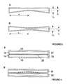
- FIG. 1is a schematic vertical cross-section through one example according to the present invention
- FIGS. 2A to Dshow different arrangements of valved and unvalved apertures
- FIGS. 3A and 3Bshow displacement profiles of driven cavity end walls
- FIG. 4shows a pump having both upper and lower end walls driven
- FIGS. 5A and 5Bshow tapered cavities
- FIGS. 6A and 6Bshow a schematic and displacement profile of a two-cavity pump where the cavities share a common end wall
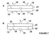
- FIGS. 7A and 7Bshow different arrangements of valved and unvalved apertures for the two-cavity pump of FIGS. 6A and 6B .
- FIG. 1shows a schematic representation of a pump 10 according to the present invention.
- a cavity 11is defined by end walls 12 and 13 , and a side wall 14 .
- the cavityis substantially circular in shape, although elliptical and other shapes could be used.
- the cavity 11is provided with a nodal air inlet 15 , which in this example is unvalved although, as shown in FIGS. 2A to 2D , it could be valved and located substantially at the centre of the end wall 13 .
- the upper end wall 12is defined by the lower surface of a disc 17 attached to a main body 18 . The inlet and outlet pass through the main body 18 .
- the actuatorcomprises a piezoelectric disc 20 attached to a disc 17 .
- the actuatorUpon actuation, the actuator is caused to vibrate in a direction substantially perpendicular to the plane of the cavity, thereby generating radial pressure oscillations within the fluid in the cavity.
- the oscillation of the actuatoris further described with regard to FIGS. 3A , 3 B and 4 .
- FIGS. 2A to Dshow different arrangements of valved and unvalved apertures leading into and out of cavity 11 .
- two inlet apertures 15are unvalved and these are located at a point on a circle whose centre is the centre of the end wall 13 and whose radius is 0.63a.
- a valved outlet 16is located at the centre of the end wall 13 .
- both the inlet 15 and outlet 16 aperturesare valved and are located as close as possible to the centre of the lower end wall 13 .
- FIG. 2Dshows an example whereby the valved inlet 15 and outlet 16 apertures are located in the upper 12 and lower 13 end walls respectively such that they are both at the centre of the respective end wall.
- FIG. 2Cshows an arrangement whereby the inlet aperture is valved and is located at the centre of end wall 13 and two outlet apertures are provided at 0.63a away from the centre of the end wall 13 and are unvalved.
- FIG. 3Ashows one possible displacement profile of the driven wall 12 of the cavity.
- the amplitude of motionis at a maximum at the centre of the cavity and at a minimum at its edge.
- the solid curved line and arrowsindicate the wall displacement at one point in time and the dashed curved line its position one half cycle later. The displacements as drawn are exaggerated.
- FIG. 3Bshows a preferable displacement profile of the driven wall 12 , namely a Bessel function having the following characteristics:
- u ⁇ ( r )J 0 ⁇ ( k 0 ⁇ r a ) ; k 0 ⁇ 3.83
- the driven end wall and pressure oscillation in the cavityare mode-shape matched and the volume of the cavity 11 remains substantially constant.
- FIGS. 3A and 3Bonly the upper end wall 12 is driven and the arrows show the oscillatory motion of that end wall 12 .
- the arrowsindicate that both the upper 12 and lower 13 end walls are driven, such that their motion is 180° out of phase.
- FIGS. 5A and 5Billustrate a tapered cavity in which one ( FIG. 5A ) or both ( FIG. 5B ) end walls are frusto-conical in shape. It will be seen how the cavity 11 has a greater height at the radial extremes, whereas at the centre, the distance between the end walls is at a minimum. Such a shape provides an increased pressure at the centre of the cavity. Typically, the diameter of the cavity is 20 mm and h 1 is 0.25 mm and h 2 is 0.5 mm. As such, it will be appreciated how the end walls 12 and 13 are still substantially planar and substantially parallel according to the definition stated above.
- FIG. 6Ashows a two-cavity pump in which the cavities share a common end-wall.
- a first cavity 21is separated from a second cavity 22 by an actuator 23 .
- the first cavityis defined by end-wall 12 and side-wall 14 , with the other end-wall being one surface of actuator 23 .
- the second cavityis defined by end-wall 13 , side-wall 14 , and the opposite surface of actuator 23 .
- both cavitiesare driven simultaneously by the single actuator 23 .
- FIG. 6 Bshows one possible displacement profile of the actuator 23 . The positions of inlets and outlets have been omitted from FIGS. 6A and 6B for clarity.
- FIGS. 7A and 7Bshow different arrangements of valved and unvalved apertures leading into and out of cavities 21 and 22 for the two-cavity pump shown in FIGS. 6A and 6B .
- two pump inlet apertures 15are provided at 0.63 times the radius of cavity 22 away from the centre of the end wall 13 and are unvalved.
- Two pump outlet apertures 16are provided at 0.63 times the radius of cavity 21 away from the centre of the end wall 12 and are unvalved.
- the cavities 21 and 22are connected by a valved aperture 24 provided at the centre of the actuator 23 .
- valved pump inlet 15is provided at the centre of end-wall 13
- a valved pump outlet 16is provided at the centre of end-wall 12 .
- the cavities 21 and 22are connected by unvalved apertures 25 provided at 0.63 times the radius of cavities 21 and 22 .
- the radius a of the cavity 11is related to the resonant operating frequency f by the following equation:
- a ⁇ fk 0 ⁇ c 2 ⁇ ⁇ ⁇ , where c is the speed of sound in the working fluid.
- the choice of h and adetermines the frequency of operation of the pump.
- the pressure generatedis a function of the geometric amplification factor ⁇ , the resonant cavity Q-factor, the actuator velocity v, the density of the fluid ⁇ , and the speed of sound in the fluid c.
- the geometric amplification factor ⁇is given by:
- the viscous boundary layer thickness ⁇is given by:
- ⁇2 ⁇ ⁇ ⁇ ⁇ ⁇ 2 ⁇ ⁇ ⁇ ⁇ ⁇ f
- ⁇is the viscosity of the fluid.
- the displacement of the driven wall 12depends on the actuator velocity v and its frequency f, and must be less than the cavity thickness, giving:
- the maximum actuator displacementis half this value.
- V⁇ a 2 h
Landscapes
- Engineering & Computer Science (AREA)
- Mechanical Engineering (AREA)
- General Engineering & Computer Science (AREA)
- Reciprocating Pumps (AREA)
Abstract
Description
should be greater than 4×10⁻¹⁰m when pumping a liquid, but in the case of pumping a gas, it is preferable that the ratio is greater than 1×10⁻⁷m.
the lowest frequency acoustic mode becomes radial, rather than longitudinal.
In this case, as the centre of the driven
where c is the speed of sound in the working fluid.
Where μ is the viscosity of the fluid. In order for the viscous boundary layer to be less than half the cavity thickness
V=πa2h
- cavity resonant frequency—preferably >500 Hz,
- geometric amplification factor—preferably >10,
- viscous boundary layer thickness—preferably less than half the cavity thickness,
- cavity wall displacement must be less than the cavity thickness, and
cavity volume—preferably less than 1 cm3.
Claims (17)
Applications Claiming Priority (3)
| Application Number | Priority Date | Filing Date | Title |
|---|---|---|---|
| GBGB0508194.8AGB0508194D0 (en) | 2005-04-22 | 2005-04-22 | Pump |
| GB0508194.8 | 2005-04-22 | ||
| PCT/GB2006/001487WO2006111775A1 (en) | 2005-04-22 | 2006-04-21 | Pump |
Publications (2)
| Publication Number | Publication Date |
|---|---|
| US20090087323A1 US20090087323A1 (en) | 2009-04-02 |
| US8123502B2true US8123502B2 (en) | 2012-02-28 |
Family
ID=34639978
Family Applications (1)
| Application Number | Title | Priority Date | Filing Date |
|---|---|---|---|
| US11/918,796Active2029-05-05US8123502B2 (en) | 2005-04-22 | 2006-04-21 | Acoustic pump utilizing radial pressure oscillations |
Country Status (6)
| Country | Link |
|---|---|
| US (1) | US8123502B2 (en) |
| EP (1) | EP1875081B1 (en) |
| JP (1) | JP4795428B2 (en) |
| CA (1) | CA2645907C (en) |
| GB (1) | GB0508194D0 (en) |
| WO (1) | WO2006111775A1 (en) |
Cited By (42)
| Publication number | Priority date | Publication date | Assignee | Title |
|---|---|---|---|---|
| US20110070109A1 (en)* | 2008-06-05 | 2011-03-24 | Murata Manufacturing Co., Ltd. | Piezoelectric microblower |
| US20130209277A1 (en)* | 2012-02-10 | 2013-08-15 | Christopher Brian Locke | Systems and methods for monitoring a disc pump system using rfid |
| US20140017093A1 (en)* | 2012-07-05 | 2014-01-16 | Kci Licensing, Inc. | Systems and methods for regulating the reasonant frequency of a disc pump cavity |
| US20140050604A1 (en)* | 2011-02-03 | 2014-02-20 | The Technology Partnership Plc. | Pump |
| US20160377073A1 (en)* | 2014-03-07 | 2016-12-29 | Murata Manufacturing Co., Ltd. | Blower |
| US20170002839A1 (en)* | 2013-12-13 | 2017-01-05 | The Technology Partnership Plc | Acoustic-resonance fluid pump |
| US20180066642A1 (en)* | 2016-09-05 | 2018-03-08 | Microjet Technology Co., Ltd. | Fluid control device |
| US10239085B2 (en) | 2015-10-30 | 2019-03-26 | Johnson & Johnson Consumer Inc. | Aseptic aerosol misting device |
| US20190342654A1 (en)* | 2018-05-02 | 2019-11-07 | Ultrahaptics Limited | Blocking Plate Structure for Improved Acoustic Transmission Efficiency |
| US10502199B2 (en)* | 2012-07-05 | 2019-12-10 | Kci Licensing, Inc. | Systems and methods for supplying reduced pressure using a disc pump with electrostatic actuation |
| US10697449B2 (en) | 2016-09-05 | 2020-06-30 | Microjet Technology Co., Ltd. | Fluid control device |
| US10915177B2 (en) | 2016-08-03 | 2021-02-09 | Ultrahaptics Ip Ltd | Three-dimensional perceptions in haptic systems |
| US10921890B2 (en) | 2014-01-07 | 2021-02-16 | Ultrahaptics Ip Ltd | Method and apparatus for providing tactile sensations |
| US10930123B2 (en) | 2015-02-20 | 2021-02-23 | Ultrahaptics Ip Ltd | Perceptions in a haptic system |
| US20210062800A1 (en)* | 2018-05-31 | 2021-03-04 | Murata Manufacturing Co., Ltd. | Pump |
| US10943578B2 (en) | 2016-12-13 | 2021-03-09 | Ultrahaptics Ip Ltd | Driving techniques for phased-array systems |
| US11067073B2 (en) | 2016-09-05 | 2021-07-20 | Microjet Technology Co., Ltd. | Fluid control device |
| US11098951B2 (en) | 2018-09-09 | 2021-08-24 | Ultrahaptics Ip Ltd | Ultrasonic-assisted liquid manipulation |
| US11169610B2 (en) | 2019-11-08 | 2021-11-09 | Ultraleap Limited | Tracking techniques in haptic systems |
| US11189140B2 (en) | 2016-01-05 | 2021-11-30 | Ultrahaptics Ip Ltd | Calibration and detection techniques in haptic systems |
| US11204644B2 (en) | 2014-09-09 | 2021-12-21 | Ultrahaptics Ip Ltd | Method and apparatus for modulating haptic feedback |
| US11253885B2 (en) | 2015-10-30 | 2022-02-22 | Johnson & Johnson Consumer Inc. | Aseptic aerosol misting device |
| US11276281B2 (en) | 2015-02-20 | 2022-03-15 | Ultrahaptics Ip Ltd | Algorithm improvements in a haptic system |
| US11360546B2 (en) | 2017-12-22 | 2022-06-14 | Ultrahaptics Ip Ltd | Tracking in haptic systems |
| US11374586B2 (en) | 2019-10-13 | 2022-06-28 | Ultraleap Limited | Reducing harmonic distortion by dithering |
| US11378997B2 (en) | 2018-10-12 | 2022-07-05 | Ultrahaptics Ip Ltd | Variable phase and frequency pulse-width modulation technique |
| US20220316467A1 (en)* | 2019-09-11 | 2022-10-06 | Kyocera Corporation | Piezoelectric pump and pump unit |
| US11531395B2 (en) | 2017-11-26 | 2022-12-20 | Ultrahaptics Ip Ltd | Haptic effects from focused acoustic fields |
| US11543507B2 (en) | 2013-05-08 | 2023-01-03 | Ultrahaptics Ip Ltd | Method and apparatus for producing an acoustic field |
| US11550395B2 (en) | 2019-01-04 | 2023-01-10 | Ultrahaptics Ip Ltd | Mid-air haptic textures |
| US11553295B2 (en) | 2019-10-13 | 2023-01-10 | Ultraleap Limited | Dynamic capping with virtual microphones |
| US11554206B2 (en) | 2018-02-01 | 2023-01-17 | Kci Licensing, Inc. | Negative pressure wound therapy device using a vacuum generating pump providing audible therapy feedback |
| US11571704B2 (en) | 2015-10-30 | 2023-02-07 | Johnson & Johnson Consumer Inc. | Aseptic aerosol misting device |
| US11583885B2 (en) | 2015-10-30 | 2023-02-21 | Johnson & Johnson Consumer Inc. | Unit dose aseptic aerosol misting device |
| US11704983B2 (en) | 2017-12-22 | 2023-07-18 | Ultrahaptics Ip Ltd | Minimizing unwanted responses in haptic systems |
| US11715453B2 (en) | 2019-12-25 | 2023-08-01 | Ultraleap Limited | Acoustic transducer structures |
| US11727790B2 (en) | 2015-07-16 | 2023-08-15 | Ultrahaptics Ip Ltd | Calibration techniques in haptic systems |
| US11816267B2 (en) | 2020-06-23 | 2023-11-14 | Ultraleap Limited | Features of airborne ultrasonic fields |
| US11842517B2 (en) | 2019-04-12 | 2023-12-12 | Ultrahaptics Ip Ltd | Using iterative 3D-model fitting for domain adaptation of a hand-pose-estimation neural network |
| US11886639B2 (en) | 2020-09-17 | 2024-01-30 | Ultraleap Limited | Ultrahapticons |
| US12331759B2 (en) | 2020-07-31 | 2025-06-17 | Lee Ventus Ltd. | Method of making an actuator for a resonant acoustic pump |
| US12373033B2 (en) | 2019-01-04 | 2025-07-29 | Ultrahaptics Ip Ltd | Mid-air haptic textures |
Families Citing this family (106)
| Publication number | Priority date | Publication date | Assignee | Title |
|---|---|---|---|---|
| GB0224986D0 (en) | 2002-10-28 | 2002-12-04 | Smith & Nephew | Apparatus |
| GB0325129D0 (en) | 2003-10-28 | 2003-12-03 | Smith & Nephew | Apparatus in situ |
| US7779625B2 (en) | 2006-05-11 | 2010-08-24 | Kalypto Medical, Inc. | Device and method for wound therapy |
| TWI308615B (en)* | 2006-06-20 | 2009-04-11 | Ind Tech Res Inst | Micro-pump and micro-pump system |
| EP1905465B2 (en) | 2006-09-28 | 2013-11-27 | Smith & Nephew, Inc. | Portable wound therapy system |
| WO2008090725A1 (en)* | 2007-01-23 | 2008-07-31 | Nec Corporation | Diaphragm pump |
| US8485793B1 (en)* | 2007-09-14 | 2013-07-16 | Aprolase Development Co., Llc | Chip scale vacuum pump |
| DE102007050407A1 (en)* | 2007-10-22 | 2009-04-23 | Fraunhofer-Gesellschaft zur Förderung der angewandten Forschung e.V. | Pump, pump assembly and pump module |
| ES2715605T3 (en) | 2007-11-21 | 2019-06-05 | Smith & Nephew | Wound dressing |
| EP2214612B1 (en) | 2007-11-21 | 2019-05-01 | Smith & Nephew PLC | Wound dressing |
| GB0723855D0 (en) | 2007-12-06 | 2008-01-16 | Smith & Nephew | Apparatus and method for wound volume measurement |
| AU2009221772B2 (en) | 2008-03-05 | 2015-01-22 | Solventum Intellectual Properties Company | Dressing and method for applying reduced pressure to and collecting and storing fluid from a tissue site |
| GB0804739D0 (en)* | 2008-03-14 | 2008-04-16 | The Technology Partnership Plc | Pump |
| AU2012244249B2 (en)* | 2009-02-12 | 2014-03-20 | The Board Of Trustees Of The University Of Illinois | Magnetically driven micropump |
| MX2011008313A (en)* | 2009-02-12 | 2011-08-17 | S The Board Of Trustees Of The University Of Illinoi | Magnetically driven micropump. |
| US8821134B2 (en)* | 2009-06-03 | 2014-09-02 | The Technology Partnership Plc | Fluid disc pump |
| US8297947B2 (en)* | 2009-06-03 | 2012-10-30 | The Technology Partnership Plc | Fluid disc pump |
| CN105909511B (en)* | 2009-06-03 | 2019-07-12 | Kci 医疗资源有限公司 | Pump with disc-shaped cavity |
| CN102459899B (en)* | 2009-06-03 | 2016-05-11 | Kci医疗资源有限公司 | Pumps with Disc Chamber |
| RU2011154213A (en)* | 2009-06-03 | 2013-07-20 | ДЗЕ ТЕКНОЛОДЖИ ПАРТНЕРШИП ПиЭлСи | HYDRAULIC DISK PUMP |
| GB201001740D0 (en) | 2010-02-03 | 2010-03-24 | The Technology Partnership Plc | Disc pump and valve structure |
| US8646479B2 (en)* | 2010-02-03 | 2014-02-11 | Kci Licensing, Inc. | Singulation of valves |
| US8371829B2 (en)* | 2010-02-03 | 2013-02-12 | Kci Licensing, Inc. | Fluid disc pump with square-wave driver |
| CN103026066A (en)* | 2010-08-09 | 2013-04-03 | 凯希特许有限公司 | Systems and methods for measuring pressure applied by a piezoelectric pump |
| GB201015656D0 (en) | 2010-09-20 | 2010-10-27 | Smith & Nephew | Pressure control apparatus |
| US20120109034A1 (en) | 2010-10-27 | 2012-05-03 | Kci Licensing, Inc. | Interactive, wireless reduced-pressure dressings, methods, and systems |
| US9067003B2 (en) | 2011-05-26 | 2015-06-30 | Kalypto Medical, Inc. | Method for providing negative pressure to a negative pressure wound therapy bandage |
| US8974200B2 (en)* | 2011-07-08 | 2015-03-10 | International Business Machines Corporation | Device for creating fluid flow |
| JP5682513B2 (en) | 2011-09-06 | 2015-03-11 | 株式会社村田製作所 | Fluid control device |
| AU2012312898B2 (en)* | 2011-09-21 | 2016-11-17 | Solventum Intellectual Properties Company | Dual -cavity pump |
| US9084845B2 (en) | 2011-11-02 | 2015-07-21 | Smith & Nephew Plc | Reduced pressure therapy apparatuses and methods of using same |
| US8790307B2 (en) | 2011-12-01 | 2014-07-29 | Picolife Technologies, Llc | Drug delivery device and methods therefor |
| US8771229B2 (en) | 2011-12-01 | 2014-07-08 | Picolife Technologies, Llc | Cartridge system for delivery of medicament |
| GB201120887D0 (en) | 2011-12-06 | 2012-01-18 | The Technology Partnership Plc | Acoustic sensor |
| CN104321531A (en) | 2012-02-10 | 2015-01-28 | 凯希特许有限公司 | Systems and methods for electrochemical detection in a disc pump |
| JP2015510072A (en) | 2012-02-10 | 2015-04-02 | ケーシーアイ ライセンシング インコーポレイテッド | System and method for monitoring the reduced pressure provided by a disk pump system |
| CN104136777A (en) | 2012-02-10 | 2014-11-05 | 凯希特许有限公司 | Systems and methods for regulating the temperature of a disc pump system |
| GB201202346D0 (en) | 2012-02-10 | 2012-03-28 | The Technology Partnership Plc | Disc pump with advanced actuator |
| WO2013130255A1 (en) | 2012-02-29 | 2013-09-06 | Kci Licensing, Inc. | Systems and methods for supplying reduced pressure and measuring flow using a disc pump system |
| WO2013134056A1 (en) | 2012-03-07 | 2013-09-12 | Kci Licensing, Inc. | Disc pump with advanced actuator |
| US10130759B2 (en) | 2012-03-09 | 2018-11-20 | Picolife Technologies, Llc | Multi-ported drug delivery device having multi-reservoir cartridge system |
| JP6250571B2 (en) | 2012-03-12 | 2017-12-20 | スミス アンド ネフュー ピーエルシーSmith & Nephew Public Limited Company | Pressure reducing apparatus and method |
| AU2013237095B2 (en) | 2012-03-20 | 2017-10-05 | Smith & Nephew Plc | Controlling operation of a reduced pressure therapy system based on dynamic duty cycle threshold determination |
| WO2013149078A1 (en) | 2012-03-28 | 2013-10-03 | Kci Licensing, Inc. | Reduced-pressure systems, dressings, and methods facilitating separation of electronic and clinical component parts |
| US9883834B2 (en) | 2012-04-16 | 2018-02-06 | Farid Amirouche | Medication delivery device with multi-reservoir cartridge system and related methods of use |
| US9427505B2 (en) | 2012-05-15 | 2016-08-30 | Smith & Nephew Plc | Negative pressure wound therapy apparatus |
| JP5928160B2 (en) | 2012-05-29 | 2016-06-01 | オムロンヘルスケア株式会社 | Piezoelectric pump and blood pressure information measuring apparatus including the same |
| US10245420B2 (en) | 2012-06-26 | 2019-04-02 | PicoLife Technologies | Medicament distribution systems and related methods of use |
| CN108317093B (en) | 2014-02-21 | 2019-12-10 | 株式会社村田制作所 | Blower fan |
| US20150314092A1 (en)* | 2014-04-30 | 2015-11-05 | Covidien Lp | Tracheal tube with controlled-pressure cuff |
| JP6065160B2 (en) | 2014-05-20 | 2017-01-25 | 株式会社村田製作所 | Blower |
| JP6332461B2 (en) | 2014-08-20 | 2018-05-30 | 株式会社村田製作所 | Blower |
| JP6028779B2 (en)* | 2014-10-03 | 2016-11-16 | 株式会社村田製作所 | Fluid control device |
| US10983092B2 (en)* | 2014-12-11 | 2021-04-20 | The Technology Partnership Plc | Acoustic sensor |
| EP3237032B1 (en) | 2014-12-22 | 2024-08-07 | Smith & Nephew plc | Negative pressure wound therapy apparatus |
| WO2016121717A1 (en)* | 2015-01-28 | 2016-08-04 | 株式会社村田製作所 | Valve and fluid control device |
| DK3288508T3 (en) | 2015-04-27 | 2020-03-09 | Smith & Nephew | REDUCED PRESSURE DEVICES |
| WO2016199624A1 (en) | 2015-06-11 | 2016-12-15 | 株式会社村田製作所 | Pump |
| EP3426206B1 (en) | 2016-03-07 | 2023-05-10 | Smith & Nephew plc | Wound treatment apparatuses and methods with negative pressure source integrated into wound dressing |
| CA3022184A1 (en) | 2016-04-26 | 2017-11-02 | Smith & Nephew Plc | Wound dressings and methods of use with integrated negative pressure source having a fluid ingress inhibition component |
| US11096831B2 (en) | 2016-05-03 | 2021-08-24 | Smith & Nephew Plc | Negative pressure wound therapy device activation and control |
| WO2017191158A1 (en) | 2016-05-03 | 2017-11-09 | Smith & Nephew Plc | Systems and methods for driving negative pressure sources in negative pressure therapy systems |
| CA3038206A1 (en) | 2016-05-03 | 2017-11-09 | Smith & Nephew Plc | Optimizing power transfer to negative pressure sources in negative pressure therapy systems |
| DE102016009836A1 (en)* | 2016-08-15 | 2018-02-15 | Drägerwerk AG & Co. KGaA | Pneumatic control device |
| WO2018037075A1 (en) | 2016-08-25 | 2018-03-01 | Smith & Nephew Plc | Absorbent negative pressure wound therapy dressing |
| US10634130B2 (en) | 2016-09-07 | 2020-04-28 | Sung Won Moon | Compact voice coil driven high flow fluid pumps and methods |
| EP3519001B1 (en) | 2016-09-30 | 2025-05-21 | Smith & Nephew plc | Negative pressure wound treatment apparatuses and methods with integrated electronics |
| EP3551244A1 (en) | 2016-12-12 | 2019-10-16 | Smith & Nephew PLC | Pressure wound therapy status indication via external device |
| RU175857U1 (en)* | 2016-12-28 | 2017-12-21 | федеральное государственное бюджетное научное учреждение "Научно-исследовательский институт перспективных материалов и технологий" | Piezoelectric micropump |
| EP3592312B1 (en) | 2017-03-08 | 2024-01-10 | Smith & Nephew plc | Negative pressure wound therapy device control in presence of fault condition |
| JP7121050B2 (en) | 2017-05-09 | 2022-08-17 | スミス アンド ネフュー ピーエルシー | Redundant control of negative pressure wound therapy systems |
| CA3074780A1 (en) | 2017-09-13 | 2019-03-21 | Smith & Nephew Plc | Negative pressure wound treatment apparatuses and methods with integrated electronics |
| GB201718070D0 (en) | 2017-11-01 | 2017-12-13 | Smith & Nephew | Negative pressure wound treatment apparatuses and methods with integrated electronics |
| WO2019073739A1 (en) | 2017-10-10 | 2019-04-18 | 株式会社村田製作所 | Pump and fluid control device |
| US11497653B2 (en) | 2017-11-01 | 2022-11-15 | Smith & Nephew Plc | Negative pressure wound treatment apparatuses and methods with integrated electronics |
| GB201718072D0 (en) | 2017-11-01 | 2017-12-13 | Smith & Nephew | Negative pressure wound treatment apparatuses and methods with integrated electronics |
| GB201718054D0 (en) | 2017-11-01 | 2017-12-13 | Smith & Nephew | Sterilization of integrated negative pressure wound treatment apparatuses and sterilization methods |
| WO2019130853A1 (en)* | 2017-12-26 | 2019-07-04 | 株式会社村田製作所 | Pump and fluid control device |
| JP6741176B2 (en)* | 2018-01-10 | 2020-08-19 | 株式会社村田製作所 | Pumps and fluid controls |
| JP6904436B2 (en)* | 2018-01-10 | 2021-07-14 | 株式会社村田製作所 | Pump and fluid control |
| GB2569417B (en)* | 2018-07-31 | 2020-06-17 | Ttp Ventus Ltd | Microfluidic drive system |
| USD898925S1 (en) | 2018-09-13 | 2020-10-13 | Smith & Nephew Plc | Medical dressing |
| GB2577710B (en) | 2018-10-03 | 2022-12-14 | Lee Ventus Ltd | Methods and devices for driving a piezoelectric pump |
| WO2020111064A1 (en) | 2018-11-27 | 2020-06-04 | 株式会社村田製作所 | Pump |
| GB2576796B (en) | 2018-12-07 | 2020-10-07 | Ttp Ventus Ltd | Improved valve |
| EP3891398B1 (en) | 2018-12-07 | 2023-01-04 | Lee Ventus Limited | Improved valve |
| GB201903774D0 (en) | 2019-03-20 | 2019-05-01 | Smith & Nephew | Negative pressure wound treatment apparatuses and methods with integrated electronics |
| GB201907716D0 (en) | 2019-05-31 | 2019-07-17 | Smith & Nephew | Systems and methods for extending operational time of negative pressure wound treatment apparatuses |
| GB2591468A (en) | 2020-01-28 | 2021-08-04 | Ttp Ventus Ltd | Valve for controlling a flow of a fluid |
| TWI720877B (en)* | 2020-04-24 | 2021-03-01 | 研能科技股份有限公司 | Actuating and sensing module |
| CN113551828B (en)* | 2020-04-24 | 2023-07-04 | 研能科技股份有限公司 | Actuation sensing module |
| TWI720878B (en) | 2020-04-24 | 2021-03-01 | 研能科技股份有限公司 | Actuating and sensing module |
| GB2597942B (en) | 2020-08-10 | 2022-08-03 | Ttp Ventus Ltd | Pump for microfluidic device |
| DE112021005156T5 (en)* | 2020-09-30 | 2023-08-10 | Murata Manufacturing Co., Ltd. | FLUID CONTROL DEVICE |
| GB2606743B (en) | 2021-05-19 | 2023-12-27 | Lee Ventus Ltd | Microfluidic pump control |
| CN117581012A (en)* | 2021-06-24 | 2024-02-20 | 华为技术有限公司 | Thermoacoustically generated air flow device for electronic device cooling |
| GB2612629A (en) | 2021-11-08 | 2023-05-10 | Lee Ventus Ltd | Fluid control system |
| CN216847404U (en)* | 2022-01-12 | 2022-06-28 | 深圳市轩达电子有限公司 | Frequency-adjustable water dripping device |
| GB2619414A (en)* | 2022-01-12 | 2023-12-06 | Shenzhen Xuanda Electronics Co Ltd | Frequency-adjustable water dripping device |
| GB2616883A (en) | 2022-03-23 | 2023-09-27 | Lee Ventus Ltd | Improved valve |
| GB2622575B (en) | 2022-09-11 | 2025-01-08 | Bioliberty Ltd | Soft robotic assistive device |
| CN115822933A (en)* | 2022-12-23 | 2023-03-21 | 吉林大学 | A piezoelectric jet pump |
| GB2624475B (en) | 2023-02-08 | 2025-06-18 | Foster & Freeman Ltd | Volatile sampling device |
| CN117189554B (en)* | 2023-09-13 | 2024-05-28 | 深圳白边精密科技有限公司 | Acoustic pressure pump, working method and application equipment |
| WO2025190946A1 (en) | 2024-03-12 | 2025-09-18 | Bioliberty Ltd | Soft robotic assistive device |
| CN118855669A (en)* | 2024-08-26 | 2024-10-29 | 深圳白边精密科技有限公司 | A multi-vibrator connected piezoelectric pump, working method and application equipment |
Citations (4)
| Publication number | Priority date | Publication date | Assignee | Title |
|---|---|---|---|---|
| WO1993010910A1 (en) | 1991-12-04 | 1993-06-10 | The Technology Partnership Limited | Fluid droplet production apparatus and method |
| US5769608A (en)* | 1994-06-10 | 1998-06-23 | P.D. Coop, Inc. | Resonant system to pump liquids, measure volume, and detect bubbles |
| US6203291B1 (en) | 1993-02-23 | 2001-03-20 | Erik Stemme | Displacement pump of the diaphragm type having fixed geometry flow control means |
| US20040000843A1 (en) | 2000-09-18 | 2004-01-01 | East W. Joe | Piezoelectric actuator and pump using same |
Family Cites Families (5)
| Publication number | Priority date | Publication date | Assignee | Title |
|---|---|---|---|---|
| US5174130A (en)* | 1990-03-14 | 1992-12-29 | Sonic Compressor Systems, Inc. | Refrigeration system having standing wave compressor |
| DE4422743A1 (en)* | 1994-06-29 | 1996-01-04 | Torsten Gerlach | Micropump |
| DE19539020C2 (en)* | 1995-10-19 | 1999-04-22 | Siemens Ag | Pump for conveying gaseous or liquid media |
| GB0308197D0 (en)* | 2003-04-09 | 2003-05-14 | The Technology Partnership Plc | Gas flow generator |
| DE602004019419D1 (en)* | 2003-06-30 | 2009-03-26 | Nxp Bv | GENERATION DEVICE MEETS WITH THE HELP OF A MEDIA FLOW |
- 2005
- 2005-04-22GBGBGB0508194.8Apatent/GB0508194D0/ennot_activeCeased
- 2006
- 2006-04-21USUS11/918,796patent/US8123502B2/enactiveActive
- 2006-04-21CACA2645907Apatent/CA2645907C/enactiveActive
- 2006-04-21EPEP06726876.3Apatent/EP1875081B1/enactiveActive
- 2006-04-21WOPCT/GB2006/001487patent/WO2006111775A1/enactiveSearch and Examination
- 2006-04-21JPJP2008507171Apatent/JP4795428B2/enactiveActive
Patent Citations (4)
| Publication number | Priority date | Publication date | Assignee | Title |
|---|---|---|---|---|
| WO1993010910A1 (en) | 1991-12-04 | 1993-06-10 | The Technology Partnership Limited | Fluid droplet production apparatus and method |
| US6203291B1 (en) | 1993-02-23 | 2001-03-20 | Erik Stemme | Displacement pump of the diaphragm type having fixed geometry flow control means |
| US5769608A (en)* | 1994-06-10 | 1998-06-23 | P.D. Coop, Inc. | Resonant system to pump liquids, measure volume, and detect bubbles |
| US20040000843A1 (en) | 2000-09-18 | 2004-01-01 | East W. Joe | Piezoelectric actuator and pump using same |
Cited By (77)
| Publication number | Priority date | Publication date | Assignee | Title |
|---|---|---|---|---|
| US20110070109A1 (en)* | 2008-06-05 | 2011-03-24 | Murata Manufacturing Co., Ltd. | Piezoelectric microblower |
| US8684707B2 (en)* | 2008-06-05 | 2014-04-01 | Murata Manufacturing Co., Ltd. | Piezoelectric microblower |
| US10975855B2 (en)* | 2011-02-03 | 2021-04-13 | The Technology Partnership Plc. | Fluid pump including a pressure oscillation with at least one nodal diameter |
| US20140050604A1 (en)* | 2011-02-03 | 2014-02-20 | The Technology Partnership Plc. | Pump |
| US20130209277A1 (en)* | 2012-02-10 | 2013-08-15 | Christopher Brian Locke | Systems and methods for monitoring a disc pump system using rfid |
| US9422934B2 (en)* | 2012-02-10 | 2016-08-23 | Kci Licensing, Inc. | Systems and methods for monitoring a disc pump system using RFID |
| US9709042B2 (en)* | 2012-07-05 | 2017-07-18 | Kci Licensing, Inc. | Systems and methods for regulating the resonant frequency of a disc pump cavity |
| US10502199B2 (en)* | 2012-07-05 | 2019-12-10 | Kci Licensing, Inc. | Systems and methods for supplying reduced pressure using a disc pump with electrostatic actuation |
| US20140017093A1 (en)* | 2012-07-05 | 2014-01-16 | Kci Licensing, Inc. | Systems and methods for regulating the reasonant frequency of a disc pump cavity |
| US11624815B1 (en) | 2013-05-08 | 2023-04-11 | Ultrahaptics Ip Ltd | Method and apparatus for producing an acoustic field |
| US11543507B2 (en) | 2013-05-08 | 2023-01-03 | Ultrahaptics Ip Ltd | Method and apparatus for producing an acoustic field |
| US12345838B2 (en) | 2013-05-08 | 2025-07-01 | Ultrahaptics Ip Ltd | Method and apparatus for producing an acoustic field |
| US20170002839A1 (en)* | 2013-12-13 | 2017-01-05 | The Technology Partnership Plc | Acoustic-resonance fluid pump |
| US10598192B2 (en)* | 2013-12-13 | 2020-03-24 | Ttp Ventus Limited | Acoustic-resonance fluid pump |
| US10921890B2 (en) | 2014-01-07 | 2021-02-16 | Ultrahaptics Ip Ltd | Method and apparatus for providing tactile sensations |
| US10221845B2 (en)* | 2014-03-07 | 2019-03-05 | Murata Manufacturing Co., Ltd. | Blower |
| US20160377073A1 (en)* | 2014-03-07 | 2016-12-29 | Murata Manufacturing Co., Ltd. | Blower |
| US12204691B2 (en) | 2014-09-09 | 2025-01-21 | Ultrahaptics Ip Ltd | Method and apparatus for modulating haptic feedback |
| US11204644B2 (en) | 2014-09-09 | 2021-12-21 | Ultrahaptics Ip Ltd | Method and apparatus for modulating haptic feedback |
| US11656686B2 (en) | 2014-09-09 | 2023-05-23 | Ultrahaptics Ip Ltd | Method and apparatus for modulating haptic feedback |
| US11768540B2 (en) | 2014-09-09 | 2023-09-26 | Ultrahaptics Ip Ltd | Method and apparatus for modulating haptic feedback |
| US11550432B2 (en) | 2015-02-20 | 2023-01-10 | Ultrahaptics Ip Ltd | Perceptions in a haptic system |
| US10930123B2 (en) | 2015-02-20 | 2021-02-23 | Ultrahaptics Ip Ltd | Perceptions in a haptic system |
| US11830351B2 (en) | 2015-02-20 | 2023-11-28 | Ultrahaptics Ip Ltd | Algorithm improvements in a haptic system |
| US11276281B2 (en) | 2015-02-20 | 2022-03-15 | Ultrahaptics Ip Ltd | Algorithm improvements in a haptic system |
| US11727790B2 (en) | 2015-07-16 | 2023-08-15 | Ultrahaptics Ip Ltd | Calibration techniques in haptic systems |
| US12100288B2 (en) | 2015-07-16 | 2024-09-24 | Ultrahaptics Ip Ltd | Calibration techniques in haptic systems |
| US11253885B2 (en) | 2015-10-30 | 2022-02-22 | Johnson & Johnson Consumer Inc. | Aseptic aerosol misting device |
| US11571704B2 (en) | 2015-10-30 | 2023-02-07 | Johnson & Johnson Consumer Inc. | Aseptic aerosol misting device |
| US12030076B2 (en) | 2015-10-30 | 2024-07-09 | Johnson & Johnson Consumer Inc. | Unit dose aseptic aerosol misting device |
| US11583885B2 (en) | 2015-10-30 | 2023-02-21 | Johnson & Johnson Consumer Inc. | Unit dose aseptic aerosol misting device |
| US10239085B2 (en) | 2015-10-30 | 2019-03-26 | Johnson & Johnson Consumer Inc. | Aseptic aerosol misting device |
| US11189140B2 (en) | 2016-01-05 | 2021-11-30 | Ultrahaptics Ip Ltd | Calibration and detection techniques in haptic systems |
| US11714492B2 (en) | 2016-08-03 | 2023-08-01 | Ultrahaptics Ip Ltd | Three-dimensional perceptions in haptic systems |
| US12271528B2 (en) | 2016-08-03 | 2025-04-08 | Ultrahaptics Ip Ltd | Three-dimensional perceptions in haptic systems |
| US11307664B2 (en) | 2016-08-03 | 2022-04-19 | Ultrahaptics Ip Ltd | Three-dimensional perceptions in haptic systems |
| US12001610B2 (en) | 2016-08-03 | 2024-06-04 | Ultrahaptics Ip Ltd | Three-dimensional perceptions in haptic systems |
| US10915177B2 (en) | 2016-08-03 | 2021-02-09 | Ultrahaptics Ip Ltd | Three-dimensional perceptions in haptic systems |
| US10697449B2 (en) | 2016-09-05 | 2020-06-30 | Microjet Technology Co., Ltd. | Fluid control device |
| US20180066642A1 (en)* | 2016-09-05 | 2018-03-08 | Microjet Technology Co., Ltd. | Fluid control device |
| US10788028B2 (en)* | 2016-09-05 | 2020-09-29 | Microjet Technology Co., Ltd. | Fluid control device with alignment features on the flexible plate and communication plate |
| US11067073B2 (en) | 2016-09-05 | 2021-07-20 | Microjet Technology Co., Ltd. | Fluid control device |
| US10943578B2 (en) | 2016-12-13 | 2021-03-09 | Ultrahaptics Ip Ltd | Driving techniques for phased-array systems |
| US11955109B2 (en) | 2016-12-13 | 2024-04-09 | Ultrahaptics Ip Ltd | Driving techniques for phased-array systems |
| US11531395B2 (en) | 2017-11-26 | 2022-12-20 | Ultrahaptics Ip Ltd | Haptic effects from focused acoustic fields |
| US11921928B2 (en) | 2017-11-26 | 2024-03-05 | Ultrahaptics Ip Ltd | Haptic effects from focused acoustic fields |
| US11704983B2 (en) | 2017-12-22 | 2023-07-18 | Ultrahaptics Ip Ltd | Minimizing unwanted responses in haptic systems |
| US12347304B2 (en) | 2017-12-22 | 2025-07-01 | Ultrahaptics Ip Ltd | Minimizing unwanted responses in haptic systems |
| US12158522B2 (en) | 2017-12-22 | 2024-12-03 | Ultrahaptics Ip Ltd | Tracking in haptic systems |
| US11360546B2 (en) | 2017-12-22 | 2022-06-14 | Ultrahaptics Ip Ltd | Tracking in haptic systems |
| US11554206B2 (en) | 2018-02-01 | 2023-01-17 | Kci Licensing, Inc. | Negative pressure wound therapy device using a vacuum generating pump providing audible therapy feedback |
| US11883847B2 (en)* | 2018-05-02 | 2024-01-30 | Ultraleap Limited | Blocking plate structure for improved acoustic transmission efficiency |
| US20230124704A1 (en)* | 2018-05-02 | 2023-04-20 | Ultrahaptics Ip Limited | Blocking Plate Structure for Improved Acoustic Transmission Efficiency |
| US12370577B2 (en) | 2018-05-02 | 2025-07-29 | Ultrahaptics Ip Ltd | Blocking plate structure for improved acoustic transmission efficiency |
| US20190342654A1 (en)* | 2018-05-02 | 2019-11-07 | Ultrahaptics Limited | Blocking Plate Structure for Improved Acoustic Transmission Efficiency |
| US10911861B2 (en)* | 2018-05-02 | 2021-02-02 | Ultrahaptics Ip Ltd | Blocking plate structure for improved acoustic transmission efficiency |
| US11529650B2 (en)* | 2018-05-02 | 2022-12-20 | Ultrahaptics Ip Ltd | Blocking plate structure for improved acoustic transmission efficiency |
| US20210062800A1 (en)* | 2018-05-31 | 2021-03-04 | Murata Manufacturing Co., Ltd. | Pump |
| US11635072B2 (en)* | 2018-05-31 | 2023-04-25 | Murata Manufacturing Co., Ltd. | Pump |
| US11098951B2 (en) | 2018-09-09 | 2021-08-24 | Ultrahaptics Ip Ltd | Ultrasonic-assisted liquid manipulation |
| US11740018B2 (en) | 2018-09-09 | 2023-08-29 | Ultrahaptics Ip Ltd | Ultrasonic-assisted liquid manipulation |
| US11378997B2 (en) | 2018-10-12 | 2022-07-05 | Ultrahaptics Ip Ltd | Variable phase and frequency pulse-width modulation technique |
| US11550395B2 (en) | 2019-01-04 | 2023-01-10 | Ultrahaptics Ip Ltd | Mid-air haptic textures |
| US12373033B2 (en) | 2019-01-04 | 2025-07-29 | Ultrahaptics Ip Ltd | Mid-air haptic textures |
| US11842517B2 (en) | 2019-04-12 | 2023-12-12 | Ultrahaptics Ip Ltd | Using iterative 3D-model fitting for domain adaptation of a hand-pose-estimation neural network |
| US20220316467A1 (en)* | 2019-09-11 | 2022-10-06 | Kyocera Corporation | Piezoelectric pump and pump unit |
| US11374586B2 (en) | 2019-10-13 | 2022-06-28 | Ultraleap Limited | Reducing harmonic distortion by dithering |
| US11742870B2 (en) | 2019-10-13 | 2023-08-29 | Ultraleap Limited | Reducing harmonic distortion by dithering |
| US12191875B2 (en) | 2019-10-13 | 2025-01-07 | Ultraleap Limited | Reducing harmonic distortion by dithering |
| US11553295B2 (en) | 2019-10-13 | 2023-01-10 | Ultraleap Limited | Dynamic capping with virtual microphones |
| US11169610B2 (en) | 2019-11-08 | 2021-11-09 | Ultraleap Limited | Tracking techniques in haptic systems |
| US11715453B2 (en) | 2019-12-25 | 2023-08-01 | Ultraleap Limited | Acoustic transducer structures |
| US12002448B2 (en) | 2019-12-25 | 2024-06-04 | Ultraleap Limited | Acoustic transducer structures |
| US11816267B2 (en) | 2020-06-23 | 2023-11-14 | Ultraleap Limited | Features of airborne ultrasonic fields |
| US12393277B2 (en) | 2020-06-23 | 2025-08-19 | Ultraleap Limited | Features of airborne ultrasonic fields |
| US12331759B2 (en) | 2020-07-31 | 2025-06-17 | Lee Ventus Ltd. | Method of making an actuator for a resonant acoustic pump |
| US11886639B2 (en) | 2020-09-17 | 2024-01-30 | Ultraleap Limited | Ultrahapticons |
Also Published As
| Publication number | Publication date |
|---|---|
| JP4795428B2 (en) | 2011-10-19 |
| JP2008537057A (en) | 2008-09-11 |
| WO2006111775A1 (en) | 2006-10-26 |
| EP1875081B1 (en) | 2013-12-25 |
| US20090087323A1 (en) | 2009-04-02 |
| CA2645907A1 (en) | 2006-10-26 |
| CA2645907C (en) | 2011-08-09 |
| GB0508194D0 (en) | 2005-06-01 |
| EP1875081A1 (en) | 2008-01-09 |
Similar Documents
| Publication | Publication Date | Title |
|---|---|---|
| US8123502B2 (en) | Acoustic pump utilizing radial pressure oscillations | |
| CN102459899B (en) | Pumps with Disc Chamber | |
| US8297947B2 (en) | Fluid disc pump | |
| US9506463B2 (en) | Disc pump and valve structure | |
| EP2438301B1 (en) | Fluid disc pump | |
| US8821134B2 (en) | Fluid disc pump | |
| US8763633B2 (en) | Valve |
Legal Events
| Date | Code | Title | Description |
|---|---|---|---|
| AS | Assignment | Owner name:TECHNOLOGY PARTNERSHIP, THE, UNITED KINGDOM Free format text:ASSIGNMENT OF ASSIGNORS INTEREST;ASSIGNORS:BLAKEY, DAVID MARK;MCCRONE, JAMES EDWARD;SOMMERVILLE, JOHN MATTHEW;AND OTHERS;REEL/FRAME:020273/0168;SIGNING DATES FROM 20071017 TO 20071022 Owner name:TECHNOLOGY PARTNERSHIP, THE, UNITED KINGDOM Free format text:ASSIGNMENT OF ASSIGNORS INTEREST;ASSIGNORS:BLAKEY, DAVID MARK;MCCRONE, JAMES EDWARD;SOMMERVILLE, JOHN MATTHEW;AND OTHERS;SIGNING DATES FROM 20071017 TO 20071022;REEL/FRAME:020273/0168 | |
| AS | Assignment | Owner name:TECHNOLOGY PARTNERSHIP, THE, UNITED KINGDOM Free format text:CORRECT SOMVERVILLE NAME AND ADDRESS;ASSIGNORS:BLAKELY, DAVID MARK;MCCRONE, JAMES EDWARD;SOMERVILLE, JOHN MATTHEW;AND OTHERS;REEL/FRAME:020767/0720;SIGNING DATES FROM 20071017 TO 20071022 Owner name:TECHNOLOGY PARTNERSHIP, THE, UNITED KINGDOM Free format text:ASSIGNMENT OF ASSIGNORS INTEREST;ASSIGNORS:BLAKEY, DAVID MARK;MCCRONE, JAMES EDWARD;SOMERVILLE, JOHN MATTHEW;AND OTHERS;REEL/FRAME:020829/0573;SIGNING DATES FROM 20071017 TO 20071022 Owner name:TECHNOLOGY PARTNERSHIP, THE, UNITED KINGDOM Free format text:ASSIGNMENT OF ASSIGNORS INTEREST;ASSIGNORS:BLAKEY, DAVID MARK;MCCRONE, JAMES EDWARD;SOMERVILLE, JOHN MATTHEW;AND OTHERS;SIGNING DATES FROM 20071017 TO 20071022;REEL/FRAME:020829/0573 Owner name:TECHNOLOGY PARTNERSHIP, THE, UNITED KINGDOM Free format text:CORRECT SOMVERVILLE NAME AND ADDRESS;ASSIGNORS:BLAKELY, DAVID MARK;MCCRONE, JAMES EDWARD;SOMERVILLE, JOHN MATTHEW;AND OTHERS;SIGNING DATES FROM 20071017 TO 20071022;REEL/FRAME:020767/0720 | |
| FEPP | Fee payment procedure | Free format text:PAYOR NUMBER ASSIGNED (ORIGINAL EVENT CODE: ASPN); ENTITY STATUS OF PATENT OWNER: LARGE ENTITY | |
| AS | Assignment | Owner name:THE TECHNOLOGY PARTNERSHIP PLC, UNITED KINGDOM Free format text:CORRECTIVE ASSIGNMENT TO CORRECT THE ASSIGNEE NAME PREVIOUSLY RECORDED ON REEL 020273 FRAME 0168. ASSIGNOR(S) HEREBY CONFIRMS THE THE TECHNOLOGY PARTNERSHIP PLC;ASSIGNORS:BLAKEY, DAVID MARK;MCCRONE, JAMES EDWARD;SOMERVILLE, JOHN MATTHEW;AND OTHERS;SIGNING DATES FROM 20071017 TO 20071022;REEL/FRAME:027546/0410 | |
| STCF | Information on status: patent grant | Free format text:PATENTED CASE | |
| FEPP | Fee payment procedure | Free format text:PAYER NUMBER DE-ASSIGNED (ORIGINAL EVENT CODE: RMPN); ENTITY STATUS OF PATENT OWNER: LARGE ENTITY Free format text:PAYOR NUMBER ASSIGNED (ORIGINAL EVENT CODE: ASPN); ENTITY STATUS OF PATENT OWNER: LARGE ENTITY | |
| FEPP | Fee payment procedure | Free format text:PAYOR NUMBER ASSIGNED (ORIGINAL EVENT CODE: ASPN); ENTITY STATUS OF PATENT OWNER: LARGE ENTITY Free format text:PAYER NUMBER DE-ASSIGNED (ORIGINAL EVENT CODE: RMPN); ENTITY STATUS OF PATENT OWNER: LARGE ENTITY | |
| FPAY | Fee payment | Year of fee payment:4 | |
| MAFP | Maintenance fee payment | Free format text:PAYMENT OF MAINTENANCE FEE, 8TH YEAR, LARGE ENTITY (ORIGINAL EVENT CODE: M1552); ENTITY STATUS OF PATENT OWNER: LARGE ENTITY Year of fee payment:8 | |
| AS | Assignment | Owner name:TTP PLC, GREAT BRITAIN Free format text:CHANGE OF NAME;ASSIGNOR:THE TECHNOLOGY PARTNERSHIP PLC;REEL/FRAME:055955/0847 Effective date:20170223 | |
| AS | Assignment | Owner name:TTP VENTUS LIMITED, UNITED KINGDOM Free format text:ASSIGNMENT OF ASSIGNORS INTEREST;ASSIGNOR:TTP PLC;REEL/FRAME:056589/0273 Effective date:20210129 | |
| MAFP | Maintenance fee payment | Free format text:PAYMENT OF MAINTENANCE FEE, 12TH YEAR, LARGE ENTITY (ORIGINAL EVENT CODE: M1553); ENTITY STATUS OF PATENT OWNER: LARGE ENTITY Year of fee payment:12 |