US8123389B2 - LED lamp assembly with thermal management system - Google Patents
LED lamp assembly with thermal management systemDownload PDFInfo
- Publication number
- US8123389B2 US8123389B2US12/757,793US75779310AUS8123389B2US 8123389 B2US8123389 B2US 8123389B2US 75779310 AUS75779310 AUS 75779310AUS 8123389 B2US8123389 B2US 8123389B2
- Authority
- US
- United States
- Prior art keywords
- lighting system
- leds
- led
- temperature
- container
- Prior art date
- Legal status (The legal status is an assumption and is not a legal conclusion. Google has not performed a legal analysis and makes no representation as to the accuracy of the status listed.)
- Expired - Fee Related, expires
Links
- 239000012782phase change materialSubstances0.000claimsabstractdescription169
- 230000007704transitionEffects0.000claimsabstractdescription34
- 238000005286illuminationMethods0.000claimsdescription13
- 238000000034methodMethods0.000claimsdescription10
- TWRXJAOTZQYOKJ-UHFFFAOYSA-LMagnesium chlorideChemical compound[Mg+2].[Cl-].[Cl-]TWRXJAOTZQYOKJ-UHFFFAOYSA-L0.000claimsdescription4
- PMZURENOXWZQFD-UHFFFAOYSA-LSodium SulfateChemical compound[Na+].[Na+].[O-]S([O-])(=O)=OPMZURENOXWZQFD-UHFFFAOYSA-L0.000claimsdescription4
- 238000010521absorption reactionMethods0.000claimsdescription3
- RQPZNWPYLFFXCP-UHFFFAOYSA-Lbarium dihydroxideChemical compound[OH-].[OH-].[Ba+2]RQPZNWPYLFFXCP-UHFFFAOYSA-L0.000claimsdescription2
- 229910001863barium hydroxideInorganic materials0.000claimsdescription2
- 229910001629magnesium chlorideInorganic materials0.000claimsdescription2
- 229910052938sodium sulfateInorganic materials0.000claimsdescription2
- 235000011152sodium sulphateNutrition0.000claimsdescription2
- 230000008878couplingEffects0.000claims1
- 238000010168coupling processMethods0.000claims1
- 238000005859coupling reactionMethods0.000claims1
- 238000010586diagramMethods0.000description20
- 239000007788liquidSubstances0.000description12
- 238000002310reflectometryMethods0.000description7
- 230000000694effectsEffects0.000description6
- XLYOFNOQVPJJNP-UHFFFAOYSA-NwaterSubstancesOXLYOFNOQVPJJNP-UHFFFAOYSA-N0.000description6
- 230000008859changeEffects0.000description5
- 239000007790solid phaseSubstances0.000description5
- 239000007787solidSubstances0.000description4
- RYGMFSIKBFXOCR-UHFFFAOYSA-NCopperChemical compound[Cu]RYGMFSIKBFXOCR-UHFFFAOYSA-N0.000description3
- 229910052782aluminiumInorganic materials0.000description3
- XAGFODPZIPBFFR-UHFFFAOYSA-NaluminiumChemical compound[Al]XAGFODPZIPBFFR-UHFFFAOYSA-N0.000description3
- 238000001816coolingMethods0.000description3
- 229910052802copperInorganic materials0.000description3
- 239000010949copperSubstances0.000description3
- 239000007789gasSubstances0.000description3
- 238000013021overheatingMethods0.000description3
- 239000008188pelletSubstances0.000description3
- 239000012071phaseSubstances0.000description3
- 238000002135phase contrast microscopyMethods0.000description3
- 239000012080ambient airSubstances0.000description2
- 230000008901benefitEffects0.000description2
- 238000009792diffusion processMethods0.000description2
- 239000007791liquid phaseSubstances0.000description2
- 239000004065semiconductorSubstances0.000description2
- 238000003860storageMethods0.000description2
- 230000009471actionEffects0.000description1
- 239000003570airSubstances0.000description1
- 230000004888barrier functionEffects0.000description1
- 230000000903blocking effectEffects0.000description1
- 239000004020conductorSubstances0.000description1
- 238000005520cutting processMethods0.000description1
- 230000001419dependent effectEffects0.000description1
- 230000004927fusionEffects0.000description1
- 239000011521glassSubstances0.000description1
- 238000010438heat treatmentMethods0.000description1
- 230000008676importEffects0.000description1
- 235000015110jelliesNutrition0.000description1
- 239000008274jellySubstances0.000description1
- 238000004519manufacturing processMethods0.000description1
- 230000007246mechanismEffects0.000description1
- 229910052751metalInorganic materials0.000description1
- 239000002184metalSubstances0.000description1
- 239000000203mixtureSubstances0.000description1
- 238000012544monitoring processMethods0.000description1
- 230000009467reductionEffects0.000description1
- 229920006395saturated elastomerPolymers0.000description1
- 238000007789sealingMethods0.000description1
- 229910052709silverInorganic materials0.000description1
- 239000004332silverSubstances0.000description1
Images


Classifications
- F—MECHANICAL ENGINEERING; LIGHTING; HEATING; WEAPONS; BLASTING
- F21—LIGHTING
- F21V—FUNCTIONAL FEATURES OR DETAILS OF LIGHTING DEVICES OR SYSTEMS THEREOF; STRUCTURAL COMBINATIONS OF LIGHTING DEVICES WITH OTHER ARTICLES, NOT OTHERWISE PROVIDED FOR
- F21V25/00—Safety devices structurally associated with lighting devices
- F21V25/10—Safety devices structurally associated with lighting devices coming into action when lighting device is overloaded, e.g. thermal switch
- F—MECHANICAL ENGINEERING; LIGHTING; HEATING; WEAPONS; BLASTING
- F21—LIGHTING
- F21V—FUNCTIONAL FEATURES OR DETAILS OF LIGHTING DEVICES OR SYSTEMS THEREOF; STRUCTURAL COMBINATIONS OF LIGHTING DEVICES WITH OTHER ARTICLES, NOT OTHERWISE PROVIDED FOR
- F21V29/00—Protecting lighting devices from thermal damage; Cooling or heating arrangements specially adapted for lighting devices or systems
- F21V29/50—Cooling arrangements
- F21V29/51—Cooling arrangements using condensation or evaporation of a fluid, e.g. heat pipes
- F—MECHANICAL ENGINEERING; LIGHTING; HEATING; WEAPONS; BLASTING
- F21—LIGHTING
- F21V—FUNCTIONAL FEATURES OR DETAILS OF LIGHTING DEVICES OR SYSTEMS THEREOF; STRUCTURAL COMBINATIONS OF LIGHTING DEVICES WITH OTHER ARTICLES, NOT OTHERWISE PROVIDED FOR
- F21V29/00—Protecting lighting devices from thermal damage; Cooling or heating arrangements specially adapted for lighting devices or systems
- F21V29/85—Protecting lighting devices from thermal damage; Cooling or heating arrangements specially adapted for lighting devices or systems characterised by the material
- H—ELECTRICITY
- H05—ELECTRIC TECHNIQUES NOT OTHERWISE PROVIDED FOR
- H05B—ELECTRIC HEATING; ELECTRIC LIGHT SOURCES NOT OTHERWISE PROVIDED FOR; CIRCUIT ARRANGEMENTS FOR ELECTRIC LIGHT SOURCES, IN GENERAL
- H05B45/00—Circuit arrangements for operating light-emitting diodes [LED]
- H05B45/30—Driver circuits
- H—ELECTRICITY
- H05—ELECTRIC TECHNIQUES NOT OTHERWISE PROVIDED FOR
- H05B—ELECTRIC HEATING; ELECTRIC LIGHT SOURCES NOT OTHERWISE PROVIDED FOR; CIRCUIT ARRANGEMENTS FOR ELECTRIC LIGHT SOURCES, IN GENERAL
- H05B45/00—Circuit arrangements for operating light-emitting diodes [LED]
- H05B45/50—Circuit arrangements for operating light-emitting diodes [LED] responsive to malfunctions or undesirable behaviour of LEDs; responsive to LED life; Protective circuits
- H05B45/56—Circuit arrangements for operating light-emitting diodes [LED] responsive to malfunctions or undesirable behaviour of LEDs; responsive to LED life; Protective circuits involving measures to prevent abnormal temperature of the LEDs
- F—MECHANICAL ENGINEERING; LIGHTING; HEATING; WEAPONS; BLASTING
- F21—LIGHTING
- F21Y—INDEXING SCHEME ASSOCIATED WITH SUBCLASSES F21K, F21L, F21S and F21V, RELATING TO THE FORM OR THE KIND OF THE LIGHT SOURCES OR OF THE COLOUR OF THE LIGHT EMITTED
- F21Y2115/00—Light-generating elements of semiconductor light sources
- F21Y2115/10—Light-emitting diodes [LED]
Definitions
- a light-emitting diodeis a semiconductor diode that emits light when electrically biased. LEDs produce more light per watt than incandescent bulbs, and are often used in battery powered or energy-saving devices. With the advent of High Brightness LEDs, they are becoming increasingly popular in higher power applications such as flashlights, area lighting, and regular household light sources. LED performance largely depends on the efficacy (Lumens of light emitted per watt of input power), and the current level used to drive the devices. Reliability of the LEDs depends on maintaining the semiconductor junction temperature below the temperature limit specified by the manufacturer. Driving the LED hard in high ambient temperatures may result in overheating of the LED package, resulting in poor performance and eventually leading to device failure. Consequently, adequate heat-sinking or cooling is required to maintain a long lifetime for the LED, which is especially important in applications where the LED must operate over a wide range of temperatures.
- LED cooling systemsrely largely on convective mechanisms to remove heat.
- Heat convectionrefers to heat transport by an external source, such as a fan.
- the use of passive thermally conductive materials that absorb the heat and slowly rise in temperaturewould be highly impractical for longer term thermal dissipation.
- the size of a piece of aluminum needed to cool LEDs used in a typical lighting application for a time span of eight hours or morewould be so large that the aluminum would never come to saturation and the LEDs would unacceptably spike up in temperature.
- the lighting systemincludes a lamp and a first container including a first phase change material thermally connected to the lamp. Heat generated by the lamp during operation is conducted to the first phase change material.
- the systemalso includes a second container including a second phase change material thermally connected to the lamp. Heat generated by the lamp during operation is also conducted to the second phase change material, and the second phase change material has a transition point temperature lower than the transition point temperature of the first phase change material of the first container to account for a temperature drop between the second container and the first container.
- the lighting systemalso includes a temperature sensor for reducing lamp power if the lamp becomes too hot, and a mounting bracket which conducts heat away from the lamp into the fixture surrounding the lamp and subsequently convects the heat from the outside casing of the fixture into the ambient air.
- FIG. 1depicts a block diagram of a lighting system including a phase change material (PCM) according to the present technique.
- PCMphase change material
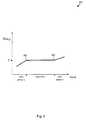
- FIG. 2depicts a graph of temperature change in a phase change material.
- FIGS. 3 a and 3 bdepict PCM units.
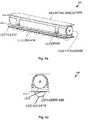
- FIGS. 4 a and 4 bdepict a diagram of a lighting system including a PCM cylinder, clamps, a mounting bracket, and a diffuser.
- FIG. 5 adepicts a diagram of a lighting system including a high reflectivity surface.
- FIGS. 5 b and 5 cdepict diagrams of a lighting system including a lens reflector.
- FIG. 6 adepicts a diagram of a lighting system including a temperature sensor.
- FIG. 6 bdepicts a diagram of a lighting system including a temperature sensor with a group of light emitting diodes (LEDs) under each lens.
- LEDslight emitting diodes
- FIG. 7depicts a block diagram of a lighting system and operational details of a temperature sensor.
- FIGS. 8 a and 8 bdepict diagrams of a lighting system with a temperature sensor in two different angled configurations.
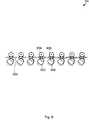
- FIG. 9depicts a diagram of a lighting array with multiple PCM cylinders.
- FIG. 10depicts several views of a lighting array.
- FIGS. 11 a and 11 bdepict diagrams of a lighting system and a candle LED lamp, respectively, with LEDs disposed at one end of a PCM unit.
- FIGS. 12 a and 12 bdepict diagrams and pictures of a lighting system installed in a sealed lighting enclosure.
- FIG. 1depicts a block diagram of lighting system 100 .
- Lighting system 100includes LED 102 , thermal connector 104 , PCM unit 106 , mounting bracket 108 , and fixture 110 .
- LED (“light emitting diode”) 102can have one or more lamps, which may be light emitting diodes, configured for illumination. LED 102 produces heat during operation that is conducted away through the other portions of lighting system 100 as discussed below.
- PCM (“phase change material”) unit 106includes, in one embodiment, a high heat latency phase change material enclosed in a thermally conductive container.
- Phase change materialstypically have a high latent heat of fusion such that a large amount of heat energy must be applied to change the PCM from, for example, a solid to a liquid, or from a solid having a first characteristic to a solid having a second characteristic.
- Illustrative PCMsare sodium sulphate, magnesium chloride, and barium hydroxide compositions. At temperatures below and above a PCM's transition point temperature, the PCM temperature rises as the PCM absorbs heat. However, at the PCM's transition point temperature, the PCM absorbs heat without increasing in temperature until a change of state occurs. As such, a PCM can “clamp” the temperature of its surroundings at its transition point temperature.
- PCM unit 106is effectively clamped at the transition point temperature until a complete PCM change of phase has occurred.
- LED 102 and PCM unit 106are coupled via thermal connector 104 so that the heat generated by LED 102 can be transferred to PCM unit 106 .
- the clamping temperature of PCM unit 106effectively clamps the temperature of LED 102 at a slightly higher temperature.
- PCM unit 106absorbs all or at least a portion of the heat or energy released into lighting system 100 while keeping a steady temperature so that lighting system 100 may continue to work within a normal working temperature range.
- the clamping effectis especially important for LED-based lighting systems because the available output capacity, efficiency, and life of an LED are highly dependent upon the LED junction temperature, and the LED junction temperature can rise if the temperature of lighting system 100 rises.
- the clamping effectcan provide benefits in several different ways. For example, in one embodiment the clamping effect can be used to drive a configuration of LEDs with a higher current, under ordinary ambient conditions, to provide more light output than would otherwise be possible or sustainable at that current. In another embodiment, the clamping effect can be used to drive a configuration of LEDs with an ordinary current, under extreme ambient conditions (e.g., in a hot desert environment), to provide more light output than would otherwise be possible or sustainable in those conditions.
- Fixture 110can be, for example, a portion of a structure to which the remainder of lighting system 100 is mounted via mounting bracket 108 .
- mounting bracket 108functions as a thermal connection between PCM unit 106 and fixture 110 in a manner similar to thermal connector 104 .
- the thermal characteristics of thermal connector 104 , PCM unit 106 , and mounting bracket 108are selected to optimize the flow of heat from LED 102 into PCM unit 106 and into fixture 110 .
- Fixture 110in some embodiments functions as a heat sink, subsequently transferring the heat into the ambient air surrounding the fixture.
- FIG. 2illustrates graph 200 , which depicts a pattern of temperature change of a PCM, such as the phase change material within PCM unit 106 in FIG. 1 , as heat is added over time.
- a PCMsuch as the phase change material within PCM unit 106 in FIG. 1
- the PCMPrior to point 202 , the PCM is in a first solid phase.
- the PCM temperaturereaches a transition point temperature and enters a phase transition state.
- the temperature of the PCMis clamped at the transition point temperature and continues to absorb heat until the PCM has reached the second solid phase at point 204 .
- the temperature of the PCMagain starts to increase, because the PCM has become saturated.
- various types of PCMscan have varying first and second phases to the left and right of points 202 and 204 , respectively.
- the types of PCM utilized by the present techniquesare not limited to PCMs having solid and liquid phases, or first solid and second solid phases, for example.
- FIG. 3 aillustrates PCM unit 300 including container 302 , which in one embodiment is a cylindrical copper tube.
- container 302can have other shapes, such as spheroid, cubic, etc.
- various embodimentsare depicted with cylindrical PCM containers, but it should be understood that those various embodiments also can have other shapes besides a cylindrical shape.
- Container 302is in one embodiment a sealed container used to contain the PCM as the PCM alternates between solid and liquid phases, although there are embodiments in which an unsealed container may also be used.
- the PCMhas a water content, and sealed container 302 prevents the water in the PCM from dehydrating to the surrounding environment.
- sealed container 302is “gas tight,” so that it tends to be substantially impermeable to gases.
- sealed container 302is metallic or metallized.
- sealed container 302may be plastic and coated with a metal film for blocking moisture transfer over many years of use.
- container 302if the PCM is sealed in interior container 304 , such as a snug-fitting plastic bag within container 302 , then container 302 does not have to be sealed.
- container 302 , interior container 304 , or bothmay function as a pressure vessel. This feature is important in embodiments in which the PCM experiences volume or density changes during heating or cooling that cause pressure changes within containers 302 and 304 . Without functioning as a pressure vessel, in some situations containers 302 and 304 can leak or otherwise fail.
- FIG. 3 billustrates PCM unit 301 including container 303 , which in one embodiment is a cylindrical copper tube similar to container 302 shown in FIG. 3 a .
- Container 303encloses PCM pellets 306 and can be configured as a heat pipe.
- Canister 303is filled at least partially with encapsulated PCM pellets 306 and partially with working liquid 307 .
- Working liquid 307can be selected for the desired operating temperature of a lighting system that includes PCM unit 301 . Water can be suitable for use as working liquid 307 for operating temperatures in the temperature range from 30° to 100° in one embodiment.
- working liquid 307can be added.
- the partial vacuum below the vapor pressure of water inside canister 303ensures that there will be both liquid and gaseous water present.
- Liquid 307sits at the base of canister 303 (depending on orientation and gravitational gradient), and when sufficient heat is applied to canister 303 from a lighting system which is thermally coupled to canister 303 , working liquid 307 vaporizes and gas 308 flows to a cooler region within canister 303 , where it condenses. The condensed liquid then falls back into working liquid 307 , or an optional wick 305 can be used that moves liquid back to working liquid 307 through capillary action.
- various embodimentsare depicted with PCM units, and it should be understood that those various embodiments can utilize PCM unit 300 or PCM unit 301 as appropriate.
- FIGS. 4 a and 4 bdepict diagrams of lighting system 400 .
- lighting system 400includes thermal connector 404 , PCM cylinder 406 , mounting bracket 408 , clamp 409 , PCB (“printed circuit board”) 412 , and LED lens 414 .
- Lighting system 400produces heat during operation that is conducted away or absorbed as discussed below.
- LEDscan be mounted on PCB 412 .
- the LEDscorrespond, in one embodiment, to LED 102 in FIG. 1 .
- PCB 412is thermally connected via thermal connector 404 to PCM cylinder 406 .
- PCM cylinder 406corresponds to PCM unit 106 in FIG. 1
- thermal connector 404corresponds to thermal connector 104 in FIG. 1 .
- Clamp 409fixes PCB 412 , thermal connector 404 , and PCM cylinder 406 to mounting bracket 408 .
- Contact part 416is included in one embodiment to improve thermal conduction between PCM cylinder 406 and mounting bracket 408 .
- the mass and shape of contact part 416can be selected to regulate the difference between, for example, heat absorption into PCM cylinder 406 and heat absorption into mounting bracket 408 .
- contact part 416is selected with a mass and shape for low thermal conductivity, so that little heat bypasses PCM cylinder 416 into and beyond mounting bracket 408 .
- contact part 416is selected with a mass and shape for high thermal conductivity, so that most heat bypasses PCM cylinder 406 .
- FIG. 4 bdepicts an end view of lighting system 400 .
- LED lens 414which is one lens among several lenses of lighting system 400 depicted in FIG. 4 a , is mounted over the LEDs to create illumination patterns.
- LED lens 414may be a hemisphere, a half hemisphere, or another shape to create various illumination patterns.
- LED lens 414can be designed to produce a uniform illumination pattern.
- an additional diffuser 426a mixing surface, can be included within or on the surface of LED lens 414 to provide improved diffusion or mixing of the light from the LEDs.
- Such mixing surfacesare particularly useful in embodiments where there are multiple LEDs under each lens, because the effect of multiple LEDs shining through the lens from different locations under the lens can be the production of unwanted images in the far field.
- Inclusion of diffuser 426can ameliorate the effect of unwanted images.
- FIG. 5 adepicts a diagram of lighting system 500 .
- Lighting system 500includes PCB (“printed circuit board”) 512 , LED lens 514 , and high reflectivity surface 518 .
- high reflectivity surface 518is a portion of PCB 512 .
- high reflectivity surface 518is a separate surface that is substantially coplanar with PCB 512 .
- High reflectivity surface 518promotes maximum light output from lighting system 500 , and can be made of, for example, polished aluminum or silver.
- FIGS. 5 b and 5 cdepict diagrams of lighting system 501 .
- FIG. 5 bdepicts a side view of one end of lighting system 501
- FIG. 5 cdepicts a bottom view of part of lighting system 501 .
- Lighting system 501corresponds, in one embodiment, to lighting system 500 in FIG. 5 a .
- Lighting system 501includes LED lens 514 , high reflectivity surface 518 , LED 522 , and reflector 524 .
- High reflectivity surface 518promotes maximum light output from lighting system 501 .
- Reflector 524disposed within lens 514 as shown in FIGS.
- each lenscan include a separate, dedicated reflector, such as reflector 524 .
- a longer reflector(not shown in FIGS. 5 b and 5 c ) that occupies the length of reflective surface 518 and passes through each of the lenses can be included. Such a longer reflector would appear substantially similar to reflector 524 as depicted in FIG. 5 b , but would extend pass the edges of lens 514 as depicted in FIG. 5 c.
- FIG. 6 adepicts a side view diagram of lighting system 600 .
- Lighting system 600includes PCB 612 , LED lens 614 , clamp 609 , and mounting bracket 608 .
- Temperature sensor 620 mounted on PCB 612 near the LEDs under LED lenses, such as LED lens 614detect over-temperature conditions and trigger current limiting circuits as needed to protect the LEDs.
- temperature sensor 620is depicted in FIG. 6 a as being separate from an LED lens, in one embodiment temperature sensor 620 is under an LED lens, closer to an LED.
- temperature sensor 620can be an external temperature monitoring sensor mounted to a suitable location in the thermal connection path and coupled to PCB 612 .
- Temperature sensor 620can be implemented as, for example, a thermistor coupled to supporting circuitry on PCB 612 .
- FIG. 6 bdepicts a bottom view diagram of lighting system 600 .
- a group of LEDscan be under each lens.
- LED 622 and LED 623are shown under lens 614 .
- the amount of light produced by lighting system 600can be reduced by turning off a portion of the LEDs under each lens without turning off all of the LEDs under any one lens.
- LED 622and corresponding LEDs under lenses other than lens 614
- LED 623and corresponding LEDs
- This method of producing half-illuminationis more suitable in many respects than a method of turning off half of the LEDs in an embodiment with only one LED under each lens, because in that embodiment half of the lens would appear dark.
- a further advantage of including multiple LEDs under each lensinvolves luminous efficiency: generally, for a given level of illumination, utilizing more LEDs yields higher luminous efficiency because each LED is responsible for less of the total luminous output, and because an LED is generally more efficient at a lower power level. Thus, for a given number of lenses, including multiple LEDs under each lens yields higher luminous efficiency.
- FIG. 7depicts LED 702 , PCM 706 , and operational details of a temperature sensor such as temperature sensor 620 in FIG. 6 .
- the temperature of LED 702is monitored by a temperature sensor, such as temperature sensor 620 , mounted near LED 702 .
- the transition point temperature of PCM 706is designed to be lower than the desired LED 702 operating temperature, T 1 , to account for temperature drop along heat path 704 between LED 702 and PCM 706 . If LED 702 temperature is too hot, i.e. T 1 >T 1 _CRITICAL, then the current driving LED 702 is automatically reduced by a circuit or by control software, as appropriate. The current can even be cut off completely if the temperature becomes so hot that damage to LED 702 could occur. The automatic reduction or cutting off can be configured to occur at a limit temperature.
- FIGS. 8 a and 8 bdepict diagrams of lighting system 800 in two configurations.
- Lighting system 800includes thermal connector 804 , PCM cylinder 806 , mounting bracket 808 , clamp 809 , PCB 812 , LED lens 814 , contact part 816 , temperature sensor 820 , and LED 822 .
- Lighting system 800produces heat during operation that is conducted away or absorbed as discussed below.
- LED 814is mounted on PCB 812 .
- PCB 812is thermally connected via thermal connector 804 to PCM cylinder 806 .
- PCM cylinder 806corresponds to PCM unit 106 in FIG. 1
- thermal connector 804corresponds to thermal connector 104 in FIG. 1 .
- Clamp 809attaches PCB 812 , thermal connector 804 , and PCM cylinder 806 to mounting bracket 808 .
- Contact part 816is included in one embodiment to improve thermal conduction between PCM cylinder 806 and mounting bracket 808 .
- LED lens 814is mounted over LED 822 to create illumination patterns and may also be mounted over temperature sensor 820 .
- LED lens 814may be hemispherical, half-hemispherical, square, rectangular, elliptical or another shape to create various illumination patterns.
- Mounting bracket 808connects lighting system 800 to a fixture, such as a wall or ceiling mount or a portion of a lamp mount, for example.
- Clamp 809may be loosened to swivel and aim portions of lighting system 800 including LED 822 in a desired direction, as depicted in FIG. 8 b .
- clamp 809need not be loosened for swiveling, but may instead be configured with a fixed tightness and sliding friction. Notably, in one embodiment such swiveling does not affect the thermal conductivity between thermal connector 804 and PCM cylinder 806 , or between PCM cylinder 806 and contact part 816 .
- FIG. 9depicts lighting array 900 , which includes fixture 930 , a group of lighting systems including lighting system 932 and lighting system 936 , and a group of independent PCM cylinders including independent PCM cylinder 934 and PCM cylinder 938 .
- the lighting systems of lighting array 900each correspond to lighting system 800 in FIG. 8 .
- the independent PCM cylinders of lighting system 900are each “standalone” PCM cylinders that are not part of a particular lighting system.
- each independent PCM cylindercan correspond, in one embodiment, to PCM unit 300 in FIG. 3 a , for example.
- independent PCM cylinders 934 , 938 , and so oncan have different shapes in various embodiments.
- fixture 930thermally connects the lighting systems to the independent PCM cylinders.
- fixture 930thermally connects lighting system 932 to independent PCM cylinder 934 .
- fixture 930also thermally connects lighting system 932 to independent PCM cylinder 938 and other independent PCM cylinders of lighting array 900 .
- fixture 930can include thermal barriers (e.g., thermal insulating portions) for thermally isolating groups of independent PCM cylinders and lighting systems.
- independent PCM cylinder 934may receive heat only from lighting system 932
- independent PCM cylinder 938may receive heat only from lighting system 936 , etc.
- the independent PCM cylinders of lighting array 900include phase change materials which are “tuned” separately from the phase change materials of the lighting systems.
- Such tuningincludes selecting phase change materials for the independent PCM cylinders having lower transition point temperatures than the transition point temperatures of the phase change materials in the lighting systems.
- independent PCM cylinder 934can be tuned to have a transition point temperature lower than the transition point temperature of the phase change material in lighting system 932 .
- One purpose of this tuningis to account for the temperature drop along the portion of fixture 930 between the independent PCM cylinder and lighting system under tuning consideration. The temperature drop occurs because, for example, some of the heat reaching fixture 930 is radiated away from or convected away from fixture 930 before reaching an independent PCM cylinder.
- the transition point temperatures of the phase change materials in the lighting systemscan be set close to and slightly lower than the safe operating LED junction temperature of the LEDs in the lighting systems, and the transition point temperatures of the phase change materials in the independent PCM cylinders can be set yet lower to account for the temperature drop across fixture 930 .
- the independent PCM cylindersprovide additional thermal storage over and above that contained in primary thermal storage 932 , and conceptually function similar to additional backup batteries, according to one analogy.
- lighting array 900has only one “tier” of independent PCM cylinders, in other embodiments lighting array 900 can have additional tiers.
- the independent PCM cylinders in the second tierare tuned to have a transition point temperature lower still than the independent PCM cylinders in the first tier (e.g., independent PCM cylinders 934 and 938 ).
- phase change material in the lighting systemswill be tuned to have a particular transition point temperature, and the phase change material in the first tier of independent PCM cylinders will have a lower transition point temperature, and the phase change material in the second tier of independent PCM cylinders will have the lowest transition point temperature.
- FIG. 10depicts several views of lighting array 1000 .
- lighting array 1000includes independent PCM cylinders that correspond to the independent PCM cylinders of lighting array 900 .
- lighting array 1000includes a lighting system that corresponds, in one embodiment, to a lighting system in lighting array 900 .
- lighting array 1000is depicted as having only one lighting system, in another embodiment it may have a group of lighting systems.
- independent PCM cylindersare arranged adjacent to the lighting system, on one side of a fixture corresponding, in one embodiment, to fixture 930 of lighting array 900 . Because the lighting system and independent PCM cylinders are on one side of the fixture, lighting array 1000 maybe well suited for flush attachment of the fixture on a surface.
- the independent PCM cylinders of lighting array 1000can include phase change materials which are “tuned” in the manner of lighting array 900 .
- FIG. 10depicts lighting array 900 as having only one pair of independent PCM cylinders, in other embodiments lighting array 900 can have additional pairs, at greater distances from the lighting system, in the manner of the tiers discussed with respect to lighting array 900 .
- the independent PCM cylinders in the outer pairare tuned to have a transition point temperature lower still than the independent PCM cylinders in the inner pair (i.e., the pair depicted in FIG. 10 ).
- FIGS. 11 a and 11 bdepict diagrams of lighting system 1100 and candle LED lamp 1101 , respectively.
- heatgenerally flows along a length of a PCM cylinder, rather than across a diameter of a PCM cylinder.
- the lampse.g., LED 1122
- the lampsare disposed at one end of a PCM cylinder, rather than along a length of a PCM cylinder.
- lighting system 1100includes thermal connector 1104 , PCM cylinder 1106 , mounting bracket 1108 , LED 1122 , and diffuser 1126 .
- LED 1122can be mounted on a PCB (not shown) that is itself mounted on thermal connector 1104 .
- Thermal connector 1104can be, for example, a copper slug.
- LED 1122corresponds, in one embodiment, to LED 102 in FIG. 1 .
- PCM cylinder 1106corresponds to PCM unit 106 in FIG. 1
- thermal connector 1104corresponds to thermal connector 104 in FIG. 1 .
- PCM cylinder 1106can correspond to PCM unit 300 or 301 depicted in FIGS. 3 a and 3 b , respectively.
- diffuser 1126a mixing surface, is included to provide improved diffusion or mixing of the light from LED 1122 .
- Candle led lamp 1101shown in FIG. 11 b , is similar in lighting system 1100 in several regards.
- One difference shown in FIG. 11 bis the inclusion of an LED array on a flexible circuit board, which may included or may be substituted for a PCB.
- FIG. 11 bdoes not depict diffuser 1126 or an LED lens, but in another embodiment either may be included in candle LED lamp 1101 .
- FIG. 12 adepicts lighting system 1100 included in sealed lighting enclosure 1200 .
- FIG. 21 bdepicts a picture of one illustrative embodiment of lighting system 1100 .
- Sealed lighting enclosure 1200includes base 1204 and cover 1202 .
- Base 1204includes a mounting fixture (e.g., a wall mount fixture) for attaching to a surface.
- Cover 1202is, in one embodiment, a glass “jelly jar” cover configured to be screwed into base 1204 , to seal sealed lighting enclosure 1200 .
- sealed lighting enclosure 1200is, in various embodiments, weatherproof, water resistant, or airtight.
- sealed lighting enclosure 1200is also heat insulated, such that sealed lighting enclosure 1200 does not provide a high thermal conductivity path from lighting system 1100 to the exterior environment.
- conventional LED lighting solutionsinstalled in sealed lighting system 1100 , are prone to failure from overheating.
- the PCM included in lighting system 1100i.e., in PCM cylinder 1106 ) serves to store thermal energy from operation and thereby prevent overheating despite the sealed nature of sealed lighting enclosure 1200 .
Landscapes
- Engineering & Computer Science (AREA)
- General Engineering & Computer Science (AREA)
- Arrangement Of Elements, Cooling, Sealing, Or The Like Of Lighting Devices (AREA)
- Non-Portable Lighting Devices Or Systems Thereof (AREA)
Abstract
Description
Claims (18)
Priority Applications (4)
| Application Number | Priority Date | Filing Date | Title |
|---|---|---|---|
| US12/757,793US8123389B2 (en) | 2010-02-12 | 2010-04-09 | LED lamp assembly with thermal management system |
| PCT/US2010/035653WO2011099990A1 (en) | 2010-02-12 | 2010-05-20 | Led lamp assembley with thermal management system |
| TW099129506ATW201131104A (en) | 2010-02-12 | 2010-09-01 | LED lamp assembly with thermal management system |
| US13/403,853US8783894B2 (en) | 2010-02-12 | 2012-02-23 | LED lamp assembly with thermal management system |
Applications Claiming Priority (2)
| Application Number | Priority Date | Filing Date | Title |
|---|---|---|---|
| US30435910P | 2010-02-12 | 2010-02-12 | |
| US12/757,793US8123389B2 (en) | 2010-02-12 | 2010-04-09 | LED lamp assembly with thermal management system |
Related Child Applications (1)
| Application Number | Title | Priority Date | Filing Date |
|---|---|---|---|
| US13/403,853ContinuationUS8783894B2 (en) | 2010-02-12 | 2012-02-23 | LED lamp assembly with thermal management system |
Publications (2)
| Publication Number | Publication Date |
|---|---|
| US20110134645A1 US20110134645A1 (en) | 2011-06-09 |
| US8123389B2true US8123389B2 (en) | 2012-02-28 |
Family
ID=44081848
Family Applications (2)
| Application Number | Title | Priority Date | Filing Date |
|---|---|---|---|
| US12/757,793Expired - Fee RelatedUS8123389B2 (en) | 2010-02-12 | 2010-04-09 | LED lamp assembly with thermal management system |
| US13/403,853Expired - Fee RelatedUS8783894B2 (en) | 2010-02-12 | 2012-02-23 | LED lamp assembly with thermal management system |
Family Applications After (1)
| Application Number | Title | Priority Date | Filing Date |
|---|---|---|---|
| US13/403,853Expired - Fee RelatedUS8783894B2 (en) | 2010-02-12 | 2012-02-23 | LED lamp assembly with thermal management system |
Country Status (3)
| Country | Link |
|---|---|
| US (2) | US8123389B2 (en) |
| TW (1) | TW201131104A (en) |
| WO (1) | WO2011099990A1 (en) |
Cited By (5)
| Publication number | Priority date | Publication date | Assignee | Title |
|---|---|---|---|---|
| US20090219726A1 (en)* | 2008-03-02 | 2009-09-03 | Matt Weaver | Thermal storage system using phase change materials in led lamps |
| US8427036B2 (en) | 2009-02-10 | 2013-04-23 | Lumenetix, Inc. | Thermal storage system using encapsulated phase change materials in LED lamps |
| US8632227B2 (en) | 2008-03-02 | 2014-01-21 | Lumenetix, Inc. | Heat removal system and method for light emitting diode lighting apparatus |
| US8783894B2 (en) | 2010-02-12 | 2014-07-22 | Lumenetix, Inc. | LED lamp assembly with thermal management system |
| US10578510B2 (en)* | 2016-11-28 | 2020-03-03 | Applied Materials, Inc. | Device for desorbing molecules from chamber walls |
Families Citing this family (34)
| Publication number | Priority date | Publication date | Assignee | Title |
|---|---|---|---|---|
| US20120313547A1 (en)* | 2011-06-10 | 2012-12-13 | Honeywell International Inc. | Aircraft led landing or taxi lights with thermal management |
| US9223138B2 (en) | 2011-12-23 | 2015-12-29 | Microsoft Technology Licensing, Llc | Pixel opacity for augmented reality |
| US9606586B2 (en) | 2012-01-23 | 2017-03-28 | Microsoft Technology Licensing, Llc | Heat transfer device |
| US8934235B2 (en) | 2012-01-23 | 2015-01-13 | Microsoft Corporation | Heat transfer device with phase change material |
| US9726887B2 (en) | 2012-02-15 | 2017-08-08 | Microsoft Technology Licensing, Llc | Imaging structure color conversion |
| US9297996B2 (en) | 2012-02-15 | 2016-03-29 | Microsoft Technology Licensing, Llc | Laser illumination scanning |
| US9779643B2 (en) | 2012-02-15 | 2017-10-03 | Microsoft Technology Licensing, Llc | Imaging structure emitter configurations |
| US9578318B2 (en) | 2012-03-14 | 2017-02-21 | Microsoft Technology Licensing, Llc | Imaging structure emitter calibration |
| US11068049B2 (en) | 2012-03-23 | 2021-07-20 | Microsoft Technology Licensing, Llc | Light guide display and field of view |
| US10191515B2 (en) | 2012-03-28 | 2019-01-29 | Microsoft Technology Licensing, Llc | Mobile device light guide display |
| US9558590B2 (en) | 2012-03-28 | 2017-01-31 | Microsoft Technology Licensing, Llc | Augmented reality light guide display |
| US9717981B2 (en) | 2012-04-05 | 2017-08-01 | Microsoft Technology Licensing, Llc | Augmented reality and physical games |
| US10502876B2 (en) | 2012-05-22 | 2019-12-10 | Microsoft Technology Licensing, Llc | Waveguide optics focus elements |
| US8989535B2 (en) | 2012-06-04 | 2015-03-24 | Microsoft Technology Licensing, Llc | Multiple waveguide imaging structure |
| US20140021884A1 (en) | 2012-07-18 | 2014-01-23 | Dialight Corporation | High ambient temperature led luminaire with thermal compensation circuitry |
| US9311909B2 (en) | 2012-09-28 | 2016-04-12 | Microsoft Technology Licensing, Llc | Sensed sound level based fan speed adjustment |
| US10192358B2 (en) | 2012-12-20 | 2019-01-29 | Microsoft Technology Licensing, Llc | Auto-stereoscopic augmented reality display |
| USD744156S1 (en)* | 2014-06-25 | 2015-11-24 | Martin Professional Aps | Light lens |
| US9304235B2 (en) | 2014-07-30 | 2016-04-05 | Microsoft Technology Licensing, Llc | Microfabrication |
| US10678412B2 (en) | 2014-07-31 | 2020-06-09 | Microsoft Technology Licensing, Llc | Dynamic joint dividers for application windows |
| US10592080B2 (en) | 2014-07-31 | 2020-03-17 | Microsoft Technology Licensing, Llc | Assisted presentation of application windows |
| US10254942B2 (en) | 2014-07-31 | 2019-04-09 | Microsoft Technology Licensing, Llc | Adaptive sizing and positioning of application windows |
| CN104373912A (en)* | 2014-11-03 | 2015-02-25 | 合肥万合科技信息服务有限公司 | Heat dissipating shell of LED lamp |
| US9372347B1 (en) | 2015-02-09 | 2016-06-21 | Microsoft Technology Licensing, Llc | Display system |
| US10317677B2 (en) | 2015-02-09 | 2019-06-11 | Microsoft Technology Licensing, Llc | Display system |
| US9827209B2 (en) | 2015-02-09 | 2017-11-28 | Microsoft Technology Licensing, Llc | Display system |
| US10018844B2 (en) | 2015-02-09 | 2018-07-10 | Microsoft Technology Licensing, Llc | Wearable image display system |
| US11086216B2 (en) | 2015-02-09 | 2021-08-10 | Microsoft Technology Licensing, Llc | Generating electronic components |
| US9423360B1 (en) | 2015-02-09 | 2016-08-23 | Microsoft Technology Licensing, Llc | Optical components |
| US9535253B2 (en) | 2015-02-09 | 2017-01-03 | Microsoft Technology Licensing, Llc | Display system |
| US9429692B1 (en) | 2015-02-09 | 2016-08-30 | Microsoft Technology Licensing, Llc | Optical components |
| US9513480B2 (en) | 2015-02-09 | 2016-12-06 | Microsoft Technology Licensing, Llc | Waveguide |
| CA2996646A1 (en)* | 2015-08-26 | 2017-03-02 | Thin Thermal Exchange Pte Ltd | Evacuated core circuit board |
| US10674641B2 (en)* | 2016-04-04 | 2020-06-02 | Hamilton Sundstrand Corporation | Immersion cooling systems and methods |
Citations (46)
| Publication number | Priority date | Publication date | Assignee | Title |
|---|---|---|---|---|
| US3316497A (en) | 1965-07-09 | 1967-04-25 | Robert R Brooks | Phase controlled oscillator loop with variable passband filter |
| US3390341A (en) | 1964-07-24 | 1968-06-25 | North American Rockwell | Voltage sensitive integration circuit |
| US3654563A (en) | 1965-10-15 | 1972-04-04 | Gen Electric | Active filter circuit having nonlinear properties |
| US4237023A (en) | 1979-03-20 | 1980-12-02 | Massachusetts Institute Of Technology | Aqueous heat-storage compositions containing fumed silicon dioxide and having prolonged heat-storage efficiencies |
| US4504402A (en) | 1983-06-13 | 1985-03-12 | Pennwalt Corporation | Encapsulated phase change thermal energy _storage materials |
| US4581285A (en) | 1983-06-07 | 1986-04-08 | The United States Of America As Represented By The Secretary Of The Air Force | High thermal capacitance multilayer thermal insulation |
| US4749951A (en) | 1984-06-13 | 1988-06-07 | Mitsubishi Denki Kabushiki Kaisha | Low-pass filter circuit with variable time constant |
| US5315154A (en) | 1993-05-14 | 1994-05-24 | Hughes Aircraft Company | Electronic assembly including heat absorbing material for limiting temperature through isothermal solid-solid phase transition |
| EP0612105A1 (en) | 1993-02-19 | 1994-08-24 | Fujitsu Limited | Heat sink structure for cooling a substrate and an electronic apparatus having such a heat sink structure |
| US5722482A (en) | 1992-07-14 | 1998-03-03 | Buckley; Theresa M. | Phase change thermal control materials, method and apparatus |
| JP2002057262A (en) | 2000-06-08 | 2002-02-22 | Merck Patent Gmbh | Method of using phase changing material in heat sink for semiconductor component |
| US6452217B1 (en) | 2000-06-30 | 2002-09-17 | General Electric Company | High power LED lamp structure using phase change cooling enhancements for LED lighting products |
| US20020147242A1 (en) | 2001-02-20 | 2002-10-10 | Salyer Ival O. | Micropore open cell foam composite and method for manufacturing same |
| WO2002086795A1 (en) | 2001-04-19 | 2002-10-31 | The Charles Stark Draper Laboratory, Inc. | Charge amplifier device having fully integrated dc stabilization |
| US6482332B1 (en) | 1999-03-12 | 2002-11-19 | Ted J. Malach | Phase change formulation |
| US20040057234A1 (en) | 2002-09-19 | 2004-03-25 | Ferenc Mohacsi | High-intensity directional light |
| US20040113044A1 (en) | 2002-12-13 | 2004-06-17 | Advanced Display Inc. | Light source unit and display device |
| US20040159422A1 (en) | 2003-02-18 | 2004-08-19 | Jon Zuo | Heat pipe having a wick structure containing phase change materials |
| JP2004319658A (en) | 2003-04-15 | 2004-11-11 | Nippon Buroaa Kk | Electronic cooler |
| KR20050004708A (en) | 2004-10-05 | 2005-01-12 | 손성택 | Oscillation-Controlled Repeater in Wireless Communication System |
| US20050158687A1 (en) | 2002-07-25 | 2005-07-21 | Dahm Jonathan S. | Method and apparatus for using light emitting diodes for curing |
| US20050196720A1 (en)* | 2000-03-08 | 2005-09-08 | Tir Systems Ltd. | Light emitting diode light source for curing dental composites |
| US20050231983A1 (en) | 2002-08-23 | 2005-10-20 | Dahm Jonathan S | Method and apparatus for using light emitting diodes |
| US20050276053A1 (en) | 2003-12-11 | 2005-12-15 | Color Kinetics, Incorporated | Thermal management methods and apparatus for lighting devices |
| US20060044804A1 (en)* | 2002-04-23 | 2006-03-02 | Masato Ono | Lighting apparatus |
| US20060044059A1 (en) | 2004-08-24 | 2006-03-02 | Flying Mole Corporation | Feedback circuit |
| US20060086096A1 (en) | 2004-10-22 | 2006-04-27 | Nanocoolers, Inc. | Thermoelectric cooling and/or moderation of transient thermal load using phase change material |
| US20060151146A1 (en) | 2001-01-26 | 2006-07-13 | Chou Der J | Phase-change heat reservoir device for transient thermal management |
| EP1717632A1 (en) | 2005-04-29 | 2006-11-02 | Samsung Electronics Co., Ltd. | Cooling arrangement for a liquid crystal display |
| JP2007080463A (en) | 2005-09-16 | 2007-03-29 | Ricoh Co Ltd | Multilayer phase change optical recording medium and recording method therefor |
| US20070114010A1 (en) | 2005-11-09 | 2007-05-24 | Girish Upadhya | Liquid cooling for backlit displays |
| US20070125522A1 (en) | 2005-12-05 | 2007-06-07 | Nvidia Corporation | Embedded heat pipe in a hybrid cooling system |
| US7252140B2 (en) | 2004-09-03 | 2007-08-07 | Nuveatix, Inc. | Apparatus and method for enhanced heat transfer |
| US20070230183A1 (en) | 2006-03-31 | 2007-10-04 | Shuy Geoffrey W | Heat exchange enhancement |
| US20070268694A1 (en) | 2006-04-18 | 2007-11-22 | Lamina Ceramics, Inc. | Optical devices for controlled color mixing |
| US20070279921A1 (en) | 2006-05-30 | 2007-12-06 | Clayton Alexander | Lighting assembly having a heat dissipating housing |
| US20080094850A1 (en) | 2004-09-16 | 2008-04-24 | Magna International Inc. | Thermal Management System for Solid State Automotive Lighting |
| US20080285271A1 (en) | 2007-05-04 | 2008-11-20 | Philips Solid-State Lighting Solutions, Inc. | Led-based fixtures and related methods for thermal management |
| WO2009001254A2 (en) | 2007-06-27 | 2008-12-31 | Nxp B.V. | Pulse width modulation circuit and class-d amplifier comprising the pwm circuit |
| US20090021944A1 (en) | 2007-07-18 | 2009-01-22 | Fu Zhun Precision Industry (Shen Zhen) Co., Ltd. | Led lamp |
| WO2009010987A1 (en) | 2007-07-19 | 2009-01-22 | Natco Pharma Limited | An improved process for the preparation of pure palonosetron hydrochloride |
| US20090219726A1 (en) | 2008-03-02 | 2009-09-03 | Matt Weaver | Thermal storage system using phase change materials in led lamps |
| US20090273921A1 (en) | 2006-07-17 | 2009-11-05 | Liquidleds Lighting Corp. | High power LED lamp with heat dissipation enhancement |
| US7810965B2 (en) | 2008-03-02 | 2010-10-12 | Lumenetix, Inc. | Heat removal system and method for light emitting diode lighting apparatus |
| US20100295468A1 (en)* | 2007-09-05 | 2010-11-25 | Martin Professional A/S | Led bar |
| US20110084608A1 (en)* | 2009-10-08 | 2011-04-14 | Jerry Lin | Led-based lighting system for retrofitting fluorescent lighting fixtures in a transit vehicle |
Family Cites Families (40)
| Publication number | Priority date | Publication date | Assignee | Title |
|---|---|---|---|---|
| US3720198A (en) | 1969-06-04 | 1973-03-13 | Laing Nikolaus | Heat storage elements, a method for producing them and devices comprising heat storage elements |
| US4419716A (en) | 1983-01-03 | 1983-12-06 | Stephen Koo | Vapor proof housing assembly and system |
| US4617332A (en) | 1984-08-31 | 1986-10-14 | University Of Dayton | Phase change compositions |
| US4797160A (en) | 1984-08-31 | 1989-01-10 | University Of Dayton | Phase change compositions |
| US5087508A (en) | 1990-05-30 | 1992-02-11 | Minnesota Mining And Manufacturing Company | Dew and frost resistant signs |
| US6227285B1 (en) | 1992-12-02 | 2001-05-08 | Schümann Sasol Gmbh & Co. Kg | Heat storage medium |
| US6104611A (en) | 1995-10-05 | 2000-08-15 | Nortel Networks Corporation | Packaging system for thermally controlling the temperature of electronic equipment |
| US5890794A (en) | 1996-04-03 | 1999-04-06 | Abtahi; Homayoon | Lighting units |
| US5831831A (en) | 1997-03-27 | 1998-11-03 | Ford Motor Company | Bonding material and phase change material system for heat burst dissipation |
| US6307871B1 (en) | 1998-09-11 | 2001-10-23 | Cutting Edge Optronics, Inc. | Laser system using phase change material for thermal control |
| US6672370B2 (en) | 2000-03-14 | 2004-01-06 | Intel Corporation | Apparatus and method for passive phase change thermal management |
| US6392883B1 (en) | 2000-06-30 | 2002-05-21 | Intel Corporation | Heat exchanger having phase change material for a portable computing device |
| US6793856B2 (en) | 2000-09-21 | 2004-09-21 | Outlast Technologies, Inc. | Melt spinable concentrate pellets having enhanced reversible thermal properties |
| AU2001294772A1 (en) | 2000-09-27 | 2002-04-08 | Microtek Laboratories, Inc. | Macrocapsules containing microencapsulated phase change materials |
| US6652771B2 (en) | 2001-07-11 | 2003-11-25 | Ronald M. Carn | Phase change material blend, method for making, and devices using same |
| US7002800B2 (en) | 2002-01-25 | 2006-02-21 | Lockheed Martin Corporation | Integrated power and cooling architecture |
| US6793009B1 (en) | 2003-06-10 | 2004-09-21 | Thermal Corp. | CTE-matched heat pipe |
| JP2005073227A (en) | 2003-08-04 | 2005-03-17 | Sharp Corp | Imaging device |
| TWI225713B (en) | 2003-09-26 | 2004-12-21 | Bin-Juine Huang | Illumination apparatus of light emitting diodes and method of heat dissipation thereof |
| GB0411421D0 (en) | 2004-05-21 | 2004-06-23 | Glaxo Group Ltd | Novel compounds |
| DE102004031889B4 (en) | 2004-06-30 | 2012-07-12 | Infineon Technologies Ag | Semiconductor component with a housing and a semi-embedded in a plastic housing material semiconductor chip and method for producing the same |
| CN100569194C (en) | 2004-07-02 | 2009-12-16 | 迪斯卡斯牙科有限责任公司 | Dentistry luminescence device with improved radiator |
| US20100096993A1 (en)* | 2004-11-29 | 2010-04-22 | Ian Ashdown | Integrated Modular Lighting Unit |
| KR100711617B1 (en) | 2005-06-02 | 2007-04-27 | 금호타이어 주식회사 | Rubber composition for tire cap ply with improved heat generation |
| US7676915B2 (en) | 2005-09-22 | 2010-03-16 | The Artak Ter-Hovhanissian Patent Trust | Process for manufacturing an LED lamp with integrated heat sink |
| US7329033B2 (en) | 2005-10-25 | 2008-02-12 | Visteon Global Technologies, Inc. | Convectively cooled headlamp assembly |
| DE102005054508A1 (en) | 2005-11-16 | 2007-05-31 | Hella Kgaa Hueck & Co. | Headlight or lamp for vehicles |
| TWI262276B (en) | 2005-11-24 | 2006-09-21 | Ind Tech Res Inst | Illumination module |
| US7600176B2 (en) | 2006-03-07 | 2009-10-06 | Broadcom Corporation | Performing multiple Reed-Solomon (RS) software error correction coding (ECC) Galois field computations simultaneously |
| US20070253202A1 (en) | 2006-04-28 | 2007-11-01 | Chaun-Choung Technology Corp. | LED lamp and heat-dissipating structure thereof |
| US20070279862A1 (en) | 2006-06-06 | 2007-12-06 | Jia-Hao Li | Heat-Dissipating Structure For Lamp |
| US7889421B2 (en) | 2006-11-17 | 2011-02-15 | Rensselaer Polytechnic Institute | High-power white LEDs and manufacturing method thereof |
| US8192841B2 (en) | 2006-12-14 | 2012-06-05 | Kimberly-Clark Worldwide, Inc. | Microencapsulated delivery vehicle having an aqueous core |
| US8262263B2 (en) | 2007-11-16 | 2012-09-11 | Khanh Dinh | High reliability cooling system for LED lamps using dual mode heat transfer loops |
| CN101334155A (en) | 2008-06-10 | 2008-12-31 | 和谐光电科技(泉州)有限公司 | High radiation led lamp radiating module |
| KR100957936B1 (en) | 2008-07-18 | 2010-05-13 | 삼성모바일디스플레이주식회사 | LCD and its driving method |
| CN101725948A (en) | 2008-10-28 | 2010-06-09 | 富准精密工业(深圳)有限公司 | Light-emitting diode lamp |
| US7969075B2 (en) | 2009-02-10 | 2011-06-28 | Lumenetix, Inc. | Thermal storage system using encapsulated phase change materials in LED lamps |
| CN101865370B (en) | 2009-04-16 | 2013-08-07 | 富准精密工业(深圳)有限公司 | Light-emitting diode lamp |
| US8123389B2 (en) | 2010-02-12 | 2012-02-28 | Lumenetix, Inc. | LED lamp assembly with thermal management system |
- 2010
- 2010-04-09USUS12/757,793patent/US8123389B2/ennot_activeExpired - Fee Related
- 2010-05-20WOPCT/US2010/035653patent/WO2011099990A1/enactiveApplication Filing
- 2010-09-01TWTW099129506Apatent/TW201131104A/enunknown
- 2012
- 2012-02-23USUS13/403,853patent/US8783894B2/ennot_activeExpired - Fee Related
Patent Citations (54)
| Publication number | Priority date | Publication date | Assignee | Title |
|---|---|---|---|---|
| US3390341A (en) | 1964-07-24 | 1968-06-25 | North American Rockwell | Voltage sensitive integration circuit |
| US3316497A (en) | 1965-07-09 | 1967-04-25 | Robert R Brooks | Phase controlled oscillator loop with variable passband filter |
| US3654563A (en) | 1965-10-15 | 1972-04-04 | Gen Electric | Active filter circuit having nonlinear properties |
| US4237023A (en) | 1979-03-20 | 1980-12-02 | Massachusetts Institute Of Technology | Aqueous heat-storage compositions containing fumed silicon dioxide and having prolonged heat-storage efficiencies |
| US4581285A (en) | 1983-06-07 | 1986-04-08 | The United States Of America As Represented By The Secretary Of The Air Force | High thermal capacitance multilayer thermal insulation |
| US4504402A (en) | 1983-06-13 | 1985-03-12 | Pennwalt Corporation | Encapsulated phase change thermal energy _storage materials |
| US4749951A (en) | 1984-06-13 | 1988-06-07 | Mitsubishi Denki Kabushiki Kaisha | Low-pass filter circuit with variable time constant |
| US5722482A (en) | 1992-07-14 | 1998-03-03 | Buckley; Theresa M. | Phase change thermal control materials, method and apparatus |
| EP0612105A1 (en) | 1993-02-19 | 1994-08-24 | Fujitsu Limited | Heat sink structure for cooling a substrate and an electronic apparatus having such a heat sink structure |
| US5315154A (en) | 1993-05-14 | 1994-05-24 | Hughes Aircraft Company | Electronic assembly including heat absorbing material for limiting temperature through isothermal solid-solid phase transition |
| US6482332B1 (en) | 1999-03-12 | 2002-11-19 | Ted J. Malach | Phase change formulation |
| US20050196720A1 (en)* | 2000-03-08 | 2005-09-08 | Tir Systems Ltd. | Light emitting diode light source for curing dental composites |
| US20020033247A1 (en) | 2000-06-08 | 2002-03-21 | Merck Patent Gmbh | Use of PCMs in heat sinks for electronic components |
| JP2002057262A (en) | 2000-06-08 | 2002-02-22 | Merck Patent Gmbh | Method of using phase changing material in heat sink for semiconductor component |
| US6452217B1 (en) | 2000-06-30 | 2002-09-17 | General Electric Company | High power LED lamp structure using phase change cooling enhancements for LED lighting products |
| US20060151146A1 (en) | 2001-01-26 | 2006-07-13 | Chou Der J | Phase-change heat reservoir device for transient thermal management |
| US20020147242A1 (en) | 2001-02-20 | 2002-10-10 | Salyer Ival O. | Micropore open cell foam composite and method for manufacturing same |
| WO2002086795A1 (en) | 2001-04-19 | 2002-10-31 | The Charles Stark Draper Laboratory, Inc. | Charge amplifier device having fully integrated dc stabilization |
| US20060044804A1 (en)* | 2002-04-23 | 2006-03-02 | Masato Ono | Lighting apparatus |
| US20050158687A1 (en) | 2002-07-25 | 2005-07-21 | Dahm Jonathan S. | Method and apparatus for using light emitting diodes for curing |
| US20080094841A1 (en) | 2002-08-23 | 2008-04-24 | Dahm Jonathan S | Method and apparatus for using light emitting diodes |
| US20050231983A1 (en) | 2002-08-23 | 2005-10-20 | Dahm Jonathan S | Method and apparatus for using light emitting diodes |
| US7345320B2 (en) | 2002-08-23 | 2008-03-18 | Dahm Jonathan S | Light emitting apparatus |
| US7989839B2 (en) | 2002-08-23 | 2011-08-02 | Koninklijke Philips Electronics, N.V. | Method and apparatus for using light emitting diodes |
| US20040057234A1 (en) | 2002-09-19 | 2004-03-25 | Ferenc Mohacsi | High-intensity directional light |
| US20040113044A1 (en) | 2002-12-13 | 2004-06-17 | Advanced Display Inc. | Light source unit and display device |
| US20040159422A1 (en) | 2003-02-18 | 2004-08-19 | Jon Zuo | Heat pipe having a wick structure containing phase change materials |
| JP2004319658A (en) | 2003-04-15 | 2004-11-11 | Nippon Buroaa Kk | Electronic cooler |
| US20050276053A1 (en) | 2003-12-11 | 2005-12-15 | Color Kinetics, Incorporated | Thermal management methods and apparatus for lighting devices |
| US20060044059A1 (en) | 2004-08-24 | 2006-03-02 | Flying Mole Corporation | Feedback circuit |
| US7279970B2 (en) | 2004-08-24 | 2007-10-09 | Flying Mole Corporation | Feedback circuit |
| US7252140B2 (en) | 2004-09-03 | 2007-08-07 | Nuveatix, Inc. | Apparatus and method for enhanced heat transfer |
| US7575354B2 (en) | 2004-09-16 | 2009-08-18 | Magna International Inc. | Thermal management system for solid state automotive lighting |
| US20080094850A1 (en) | 2004-09-16 | 2008-04-24 | Magna International Inc. | Thermal Management System for Solid State Automotive Lighting |
| KR20050004708A (en) | 2004-10-05 | 2005-01-12 | 손성택 | Oscillation-Controlled Repeater in Wireless Communication System |
| US20060086096A1 (en) | 2004-10-22 | 2006-04-27 | Nanocoolers, Inc. | Thermoelectric cooling and/or moderation of transient thermal load using phase change material |
| EP1717632A1 (en) | 2005-04-29 | 2006-11-02 | Samsung Electronics Co., Ltd. | Cooling arrangement for a liquid crystal display |
| JP2007080463A (en) | 2005-09-16 | 2007-03-29 | Ricoh Co Ltd | Multilayer phase change optical recording medium and recording method therefor |
| US20070114010A1 (en) | 2005-11-09 | 2007-05-24 | Girish Upadhya | Liquid cooling for backlit displays |
| US20070125522A1 (en) | 2005-12-05 | 2007-06-07 | Nvidia Corporation | Embedded heat pipe in a hybrid cooling system |
| US20070230183A1 (en) | 2006-03-31 | 2007-10-04 | Shuy Geoffrey W | Heat exchange enhancement |
| US20070268694A1 (en) | 2006-04-18 | 2007-11-22 | Lamina Ceramics, Inc. | Optical devices for controlled color mixing |
| US20070279921A1 (en) | 2006-05-30 | 2007-12-06 | Clayton Alexander | Lighting assembly having a heat dissipating housing |
| US20090273921A1 (en) | 2006-07-17 | 2009-11-05 | Liquidleds Lighting Corp. | High power LED lamp with heat dissipation enhancement |
| US20080285271A1 (en) | 2007-05-04 | 2008-11-20 | Philips Solid-State Lighting Solutions, Inc. | Led-based fixtures and related methods for thermal management |
| KR20100017600A (en) | 2007-05-04 | 2010-02-16 | 코닌클리즈케 필립스 일렉트로닉스 엔.브이. | Led-based fixtures and related methods for thermal management |
| WO2009001254A2 (en) | 2007-06-27 | 2008-12-31 | Nxp B.V. | Pulse width modulation circuit and class-d amplifier comprising the pwm circuit |
| US20090021944A1 (en) | 2007-07-18 | 2009-01-22 | Fu Zhun Precision Industry (Shen Zhen) Co., Ltd. | Led lamp |
| WO2009010987A1 (en) | 2007-07-19 | 2009-01-22 | Natco Pharma Limited | An improved process for the preparation of pure palonosetron hydrochloride |
| US20100295468A1 (en)* | 2007-09-05 | 2010-11-25 | Martin Professional A/S | Led bar |
| US20090219726A1 (en) | 2008-03-02 | 2009-09-03 | Matt Weaver | Thermal storage system using phase change materials in led lamps |
| US7810965B2 (en) | 2008-03-02 | 2010-10-12 | Lumenetix, Inc. | Heat removal system and method for light emitting diode lighting apparatus |
| US8047690B2 (en) | 2008-03-02 | 2011-11-01 | Lumenetix, Inc. | Heat removal system and method for light emitting diode lighting apparatus |
| US20110084608A1 (en)* | 2009-10-08 | 2011-04-14 | Jerry Lin | Led-based lighting system for retrofitting fluorescent lighting fixtures in a transit vehicle |
Non-Patent Citations (26)
| Title |
|---|
| Behr, A.T. et al., "Nonlinearities of Capacitors Realized by MOSFET Gates", Proceedings of the International Symposium on Circuits and Systems, San Diego, May 10-13, 1992 [Proceedings of the International Symposium on Circuits and Systems, (ISCAS)], New York, IEEE, US, vol. 3, May 3, 1992, pp. 1284-1287, XP010061392 ISBN: 978-0-7803-0593-9. |
| Berkhout, M., "An Integrated 200-W Class-D Audio Amplifier", IEEE Journal of Solid-State Circuits, IEEE Service Center, Piscataway, NJ, US, vol. 38, No. 7, Jul. 1, 2003, pp. 1198-1206, XP001169604. |
| Co-pending U.S. Appl. No. 12/237,313, filed Sep. 24, 2008. |
| Co-pending U.S. Appl. No. 12/368,936, filed Feb. 10, 2009. |
| Co-pending U.S. Appl. No. 12/370,521, filed Feb. 12, 2009. |
| Co-pending U.S. Appl. No. 12/892,696, filed Sep. 28, 2010. |
| Co-pending U.S. Appl. No. 13/284,773 filed Oct. 28, 2011. |
| Co-pending U.S. Appl. No. 61/032,988 filed Mar. 2, 2008. |
| Co-pending U.S. Appl. No. 61/032,989 filed Oct. 28, 2011. |
| Co-pending U.S. Appl. No. 61/304,359 filed Feb. 12, 2010. |
| Final Office Action Mailed Jan. 25, 2011 in Co-pending U.S. Appl. No. 12/358,936 filed Feb. 10, 2009. |
| Gaalaas, E. et al., "Integrated Stereo Delta Sigma Class D Amplifier", IEEE Journal of Solid-State Circuits , IEEE Service Center, Piscataway, NJ, US [online] vol. 40, No. 12, Dec. 1, 2005, pp. 2388-2397, XP002504060, issn: 0018-9200, Retrieved from the Internet: URL:http://ieeexplore.ieee.org.[retrieved on Nov. 14, 2008, pp. 2388-2392]. |
| International Search Report PCT/US2009/001253 dated May 27, 2009 pp. 1-3. |
| International Search Report PCT/US2009/001293 dated Oct, 9, 2009 pp. 1-4. |
| International Search Report PCT/US2009/069290 dated Jul. 14, 2010, pp. 1-3. |
| Non-Final Office Action Mailed Jul. 12, 2010 in Co-pending U.S. Appl. No. 12/370,521, filed Feb. 12, 2009. |
| Non-Final Office Action Mailed Mar. 16, 2011 in Co-pending U.S. Appl. No. 12/892,696 filed Sep. 28, 2010. |
| Non-Final Office Action Mailed Oct. 28, 2010 in Co-pending U.S. Appl. No. 12/368,936, filed Feb. 10, 2009. |
| Notice of Allowance Mailed Jul. 29, 2011 in Co-pending U.S. Appl. No. 12/892,696 filed Sep. 28, 2010. |
| Notice of Allowance Mailed Mar. 2, 2011 in Co-pending U.S. Appl. No. 12/358,936 filed Feb. 10, 2009. |
| Notice of Allowance Mailed Sep. 1, 2010 in Co-pending U.S. Appl. No. 12/370,521, filed Feb. 12, 2009. |
| Restriction Requirement Mailed Mar. 1, 2011 in Co-pending U.S. Appl. No. 12/237,313 filed Sep. 24, 2008. |
| Wang et al., "A Nonlinear Capacitance Cancellation Technique and and its Application to a CMOS Class AB Power Amplifier", 2001 IEEE Radio Frequency Integrated Circuits (RFIC) Symposium, Digest of Papers, Phoenix, AZ, May 20-22, 2001; [IEEE Radio Frequency Integrated Circuits Symposium], New York, NY, IEEE, US, May 20, 2001, pp. 39-42, XP010551317, ISBN: 978-0/7803-6601-5, pp. 40. |
| Written Opinion PCT/US2009/001253 dated May 27, 2009 pp. 1-3. |
| Written Opinion PCT/US2009/001293 dated Oct. 9, 2009 pp. 1-7. |
| Written Opinion PCT/US2009/069290 dated Jul. 14, 2010, pp. 1-3. |
Cited By (6)
| Publication number | Priority date | Publication date | Assignee | Title |
|---|---|---|---|---|
| US20090219726A1 (en)* | 2008-03-02 | 2009-09-03 | Matt Weaver | Thermal storage system using phase change materials in led lamps |
| US8632227B2 (en) | 2008-03-02 | 2014-01-21 | Lumenetix, Inc. | Heat removal system and method for light emitting diode lighting apparatus |
| US9102857B2 (en) | 2008-03-02 | 2015-08-11 | Lumenetix, Inc. | Methods of selecting one or more phase change materials to match a working temperature of a light-emitting diode to be cooled |
| US8427036B2 (en) | 2009-02-10 | 2013-04-23 | Lumenetix, Inc. | Thermal storage system using encapsulated phase change materials in LED lamps |
| US8783894B2 (en) | 2010-02-12 | 2014-07-22 | Lumenetix, Inc. | LED lamp assembly with thermal management system |
| US10578510B2 (en)* | 2016-11-28 | 2020-03-03 | Applied Materials, Inc. | Device for desorbing molecules from chamber walls |
Also Published As
| Publication number | Publication date |
|---|---|
| TW201131104A (en) | 2011-09-16 |
| US8783894B2 (en) | 2014-07-22 |
| WO2011099990A1 (en) | 2011-08-18 |
| US20110134645A1 (en) | 2011-06-09 |
| US20120307500A1 (en) | 2012-12-06 |
Similar Documents
| Publication | Publication Date | Title |
|---|---|---|
| US8123389B2 (en) | LED lamp assembly with thermal management system | |
| US8313220B2 (en) | LED lighting fixture | |
| WO2011055659A1 (en) | Large led lighting apparatus | |
| US7969075B2 (en) | Thermal storage system using encapsulated phase change materials in LED lamps | |
| CN101943335B (en) | Light-emitting diode lamp | |
| TWI529341B (en) | Lighting assemblies and systems | |
| US8480264B2 (en) | Lighting apparatus with heat dissipation system | |
| CN101532646B (en) | Illuminating apparatus | |
| US20110193479A1 (en) | Evaporation Cooled Lamp | |
| GB2465493A (en) | Liquid cooled LED light. | |
| JP2011513989A (en) | Heat storage system using phase change material in LED lamp, heat storage method, and method of using graph showing operating range of lighting system using phase change material | |
| WO2013112262A1 (en) | Lamp structure with remote led light source | |
| US20190072266A1 (en) | LED Luminaire Having Improved Thermal Management | |
| CN103185246B (en) | Lighting device | |
| TWI491083B (en) | A light emitting diode with a superheat conduit can replace a universal platform | |
| KR20100098890A (en) | Liquid-cooling type led lamp for lighting | |
| KR20120063875A (en) | Cooling unit and lighting device having the same | |
| JP3184244U (en) | Waterproof lighting fixtures | |
| CN214790908U (en) | High-power lamp heat dissipation system, vehicle lighting device and vehicle | |
| CN110260193B (en) | Lighting device with heat dissipation function | |
| CN209819498U (en) | Marine heat abstractor | |
| TWM439146U (en) | Explosion-proof lamp with liquid cooling heat dissipation device | |
| KR101223658B1 (en) | Led lighting device having cooling module | |
| WO2008056308A1 (en) | Improvements in lighting systems | |
| TWM428303U (en) | Modualized light emitting diode lamp |
Legal Events
| Date | Code | Title | Description |
|---|---|---|---|
| AS | Assignment | Owner name:LUMENETIX, INC., CALIFORNIA Free format text:CHANGE OF NAME;ASSIGNOR:LIGHTNING BUG, INC.;REEL/FRAME:024518/0954 Effective date:20091207 | |
| AS | Assignment | Owner name:LUMENETIX, INC., CALIFORNIA Free format text:ASSIGNMENT OF ASSIGNORS INTEREST;ASSIGNORS:HITCHCOCK, ROBERT;KINGMAN, JAMES;WEAVER, MATTHEW;AND OTHERS;REEL/FRAME:024604/0734 Effective date:20100625 | |
| AS | Assignment | Owner name:PRIVOTAL CAPITAL FUND, LP, CALIFORNIA Free format text:SECURITY INTEREST;ASSIGNOR:LUMENETIX, INC.;REEL/FRAME:036584/0113 Effective date:20150916 | |
| REMI | Maintenance fee reminder mailed | ||
| LAPS | Lapse for failure to pay maintenance fees | ||
| STCH | Information on status: patent discontinuation | Free format text:PATENT EXPIRED DUE TO NONPAYMENT OF MAINTENANCE FEES UNDER 37 CFR 1.362 | |
| FP | Lapsed due to failure to pay maintenance fee | Effective date:20160228 | |
| AS | Assignment | Owner name:WESTERN ALLIANCE BANK, CALIFORNIA Free format text:SECURITY INTEREST;ASSIGNOR:LUMENETIX, INC.;REEL/FRAME:043467/0273 Effective date:20160427 | |
| AS | Assignment | Owner name:LUMENETIX, INC., CALIFORNIA Free format text:RELEASE BY SECURED PARTY;ASSIGNOR:PIVOTAL CAPITAL FUND, LP;REEL/FRAME:051357/0741 Effective date:20190614 |