US8123262B2 - Damping assembly for reducing vibrations in a latch for a vehicle door - Google Patents
Damping assembly for reducing vibrations in a latch for a vehicle doorDownload PDFInfo
- Publication number
- US8123262B2 US8123262B2US12/343,536US34353608AUS8123262B2US 8123262 B2US8123262 B2US 8123262B2US 34353608 AUS34353608 AUS 34353608AUS 8123262 B2US8123262 B2US 8123262B2
- Authority
- US
- United States
- Prior art keywords
- fluid
- forkbolt
- piston
- damping assembly
- region
- Prior art date
- Legal status (The legal status is an assumption and is not a legal conclusion. Google has not performed a legal analysis and makes no representation as to the accuracy of the status listed.)
- Expired - Fee Related, expires
Links
Images


Classifications
- F—MECHANICAL ENGINEERING; LIGHTING; HEATING; WEAPONS; BLASTING
- F16—ENGINEERING ELEMENTS AND UNITS; GENERAL MEASURES FOR PRODUCING AND MAINTAINING EFFECTIVE FUNCTIONING OF MACHINES OR INSTALLATIONS; THERMAL INSULATION IN GENERAL
- F16F—SPRINGS; SHOCK-ABSORBERS; MEANS FOR DAMPING VIBRATION
- F16F9/00—Springs, vibration-dampers, shock-absorbers, or similarly-constructed movement-dampers using a fluid or the equivalent as damping medium
- F16F9/10—Springs, vibration-dampers, shock-absorbers, or similarly-constructed movement-dampers using a fluid or the equivalent as damping medium using liquid only; using a fluid of which the nature is immaterial
- F16F9/14—Devices with one or more members, e.g. pistons, vanes, moving to and fro in chambers and using throttling effect
- F16F9/16—Devices with one or more members, e.g. pistons, vanes, moving to and fro in chambers and using throttling effect involving only straight-line movement of the effective parts
- F16F9/18—Devices with one or more members, e.g. pistons, vanes, moving to and fro in chambers and using throttling effect involving only straight-line movement of the effective parts with a closed cylinder and a piston separating two or more working spaces therein
- F16F9/20—Devices with one or more members, e.g. pistons, vanes, moving to and fro in chambers and using throttling effect involving only straight-line movement of the effective parts with a closed cylinder and a piston separating two or more working spaces therein with the piston-rod extending through both ends of the cylinder, e.g. constant-volume dampers
- Y—GENERAL TAGGING OF NEW TECHNOLOGICAL DEVELOPMENTS; GENERAL TAGGING OF CROSS-SECTIONAL TECHNOLOGIES SPANNING OVER SEVERAL SECTIONS OF THE IPC; TECHNICAL SUBJECTS COVERED BY FORMER USPC CROSS-REFERENCE ART COLLECTIONS [XRACs] AND DIGESTS
- Y10—TECHNICAL SUBJECTS COVERED BY FORMER USPC
- Y10S—TECHNICAL SUBJECTS COVERED BY FORMER USPC CROSS-REFERENCE ART COLLECTIONS [XRACs] AND DIGESTS
- Y10S292/00—Closure fasteners
- Y10S292/23—Vehicle door latches
- Y—GENERAL TAGGING OF NEW TECHNOLOGICAL DEVELOPMENTS; GENERAL TAGGING OF CROSS-SECTIONAL TECHNOLOGIES SPANNING OVER SEVERAL SECTIONS OF THE IPC; TECHNICAL SUBJECTS COVERED BY FORMER USPC CROSS-REFERENCE ART COLLECTIONS [XRACs] AND DIGESTS
- Y10—TECHNICAL SUBJECTS COVERED BY FORMER USPC
- Y10S—TECHNICAL SUBJECTS COVERED BY FORMER USPC CROSS-REFERENCE ART COLLECTIONS [XRACs] AND DIGESTS
- Y10S292/00—Closure fasteners
- Y10S292/56—Silencers
- Y—GENERAL TAGGING OF NEW TECHNOLOGICAL DEVELOPMENTS; GENERAL TAGGING OF CROSS-SECTIONAL TECHNOLOGIES SPANNING OVER SEVERAL SECTIONS OF THE IPC; TECHNICAL SUBJECTS COVERED BY FORMER USPC CROSS-REFERENCE ART COLLECTIONS [XRACs] AND DIGESTS
- Y10—TECHNICAL SUBJECTS COVERED BY FORMER USPC
- Y10T—TECHNICAL SUBJECTS COVERED BY FORMER US CLASSIFICATION
- Y10T292/00—Closure fasteners
- Y10T292/08—Bolts
- Y10T292/1043—Swinging
- Y10T292/1075—Operating means
- Y10T292/1082—Motor
Definitions
- the present inventionrelates to an assembly for reducing vibrations produced by a latch of a vehicle door.
- a vehicletypically includes a body defining an opening and a door for closing to cover the opening.
- a strikeris operatively attached to the body of the vehicle and a latch is operatively attached to the door of the vehicle.
- the latchincludes a forkbolt that defines a nose for impacting the striker and a groove for engaging the striker upon impact with the striker. As the door is closed to cover the opening, the forkbolt of the latch may impact the striker.
- the forkboltimpacts the striker, the forkbolt rotates from an unlatched position, past a latched position, to an over-travel position. After the forkbolt rotates to the over-travel position, the forkbolt reverses direction and rotates from the over-travel position to the latched position when the forkbolt stops and remains engaged with the striker to hold the door in a closed position.
- a damping assemblyis disposed within a housing of a latch assembly.
- the damping assemblyslows rotation of a forkbolt that is rotatably disposed within the latch assembly as the forkbolt rotates between an over-travel position and a latched position when latching a door of a vehicle.
- the damping assemblyincludes a first passage and a second passage.
- the first passage and the second passageare each configured to allow a fluid to flow therein.
- the first passagedefines a first inlet that is configured to allow the fluid to flow into the first passage through the first inlet and a first outlet that is configured to allow the fluid to flow out from the first passage through the first outlet.
- the second passagedefines a second inlet that is configured to allow the fluid that flowed from the first outlet of the first passage to flow into the second passage through the second inlet and a second outlet that is configured to allow the fluid to flow out from the second passage and into the first passage through the first inlet.
- a restriction passagefluidly connects the first passage and the second passage.
- a check valveis configured to allow unidirectional flow of the fluid through the passages.
- the restriction passageis configured to restrict flow of the fluid through the passages to increase a pressure of the fluid within the passages.
- An engagement mechanismis operatively connected to the passages and is configured to engage the forkbolt as the forkbolt rotates between the over-travel position and the latched position. The fluid within the passages reacts against the engagement mechanism to slow rotation of the forkbolt as the forkbolt rotates between the over-travel position and the latched position.
- a latch assemblylatches a door of a vehicle.
- the latch assemblyincludes a housing, a forkbolt, and a damping assembly.
- the housingis configured for operative attachment to the door of the vehicle.
- the forkboltis rotatably disposed within the housing for rotating between the unlatched and latched position with some range for over-travel beyond the latched position.
- the damping assemblyis disposed within the housing and is in engagement with the forkbolt as the forkbolt rotates between the over-travel position and the latched position.
- the damping assemblyis configured to slow rotation of the forkbolt as the forkbolt rotates between the over-travel position and the latched position.
- a method of reducing vibrations from latching a latch of a door of a vehicle with a strikerincludes engaging a forkbolt with an engagement mechanism of a damping assembly as the forkbolt rotates from an over-travel position to a latched position.
- the fluid within the damping assemblyis pressurized such that the pressurized fluid reacts against the engagement mechanism to slow rotation of the forkbolt as the forkbolt rotates between the over-travel position and the latched position.
- the rotation of the forkboltis slowed as the forkbolt rotates between the over-travel position and the latched position.
- noise and vibrations that are typically emitted from latching the doormay be reduced or eliminated.
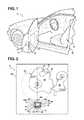
- FIG. 1is a partial perspective view of vehicle having a body with a striker and a door with a latch for engaging the striker when the door is closed relative to the body;
- FIG. 2is a schematic partial cross-sectional view of the latch having a forkbolt and a damping assembly with the forkbolt in an unlatched position;
- FIG. 3is a schematic partial cross-sectional view of the latch of FIG. 2 with the forkbolt in a latched position
- FIG. 4is a schematic partial cross-sectional view of the latch of FIG. 2 with the forkbolt engaging the striker in an over-travel position;
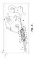
- FIG. 5is a schematic partial cross-sectional view of an alternative embodiment of the latch with the forkbolt in the unlatched position
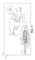
- FIG. 6is a schematic partial cross-sectional view of the latch of FIG. 5 with the forkbolt in the over-travel position;
- FIG. 7is a schematic partial cross-sectional view of the latch of FIG. 5 with the forkbolt engaging the striker and in the latched position.
- FIG. 1shows a latch assembly 10 disposed within a door 12 of a vehicle 14 for latching the door 12 to a striker 16 , attached to a body 18 of the vehicle 14 .
- the door 12 of the vehicle 14is latched, or engages, a striker 16 that is mounted to a body 18 of the vehicle 14 .
- the latch assembly 10includes a housing 20 for operative attachment of the latch assembly 10 to the door 12 of the vehicle 14 .
- a forkbolt 22is rotatably disposed within the housing 20 . This means that the forkbolt 22 rotates from an unlatched position, past a latched position, to an over-travel position.
- the forkbolt 22changes rotational direction and rotates from the over-travel position to the latched position to engage the striker 16 and hold the door 12 in a closed position. Movement of the forkbolt 22 from the unlatched position to the latched position is facilitated by closing the door 12 such that the forkbolt 22 impacts the striker 16 .
- the impact with the striker 16causes the forkbolt 22 to rotate and wrap around the striker 16 .
- Momentum from impacting the striker 16causes the forkbolt 22 to rotate past the latched position to the over-travel position while the forkbolt 22 engages the striker 16 .
- the forkbolt 22then rebounds from the over-travel position to the latched position to rest and remain at the latched position while engaging the striker 16 and holding the door 12 in the closed position.
- a damping assembly 24is disposed within, and may be operatively connected to the housing 20 of the latch assembly 10 .
- the damping assembly 24is in engagement with the forkbolt 22 as the forkbolt 22 rotates between the over-travel position and the latched position.
- the damping assembly 24slows rotation of the forkbolt 22 as the forkbolt 22 rotates between the over-travel position and the latched position to reduce vibrations and noise that are produced when the forkbolt 22 is stopped by engagement with a detent lever 30 at the latched position.
- the forkbolt 22includes an outer periphery 26 , which may be non-uniform.
- the periphery of the forkbolt 22may include a radially projecting nose 28 .
- a detent lever 30may be rotatably disposed in the housing 20 .
- the detent lever 30meshes with the nose 28 of the forkbolt 22 as the forkbolt 22 rotates to hold the forkbolt 22 in the latched position.
- the damping assembly 24may engage the forkbolt 22 proximate the periphery 26 .
- the forkbolt 22may define a groove 32 where the nose 28 extends into the groove 32 .
- the striker 16may be disposed within the groove 32 when the forkbolt 22 is in the latched position.
- the nose 28 of the forkbolt 22may impact the striker 16 such that the striker 22 is guided down the nose 28 and into the groove 32 .
- the damping assembly 24defines a first fluid region A, having a first volume V 1 , and a second fluid region B, having a second volume V 2 .
- the damping assembly 24also includes an engagement mechanism 40 .
- the engagement mechanism 40engages the forkbolt 22 to slow rotation of the forkbolt 22 .
- the fluid Fflows between the first fluid region A and the second fluid region B.
- the fluid Fmay be a hydraulic fluid such as oil and the like. It should be appreciated, however, that other fluids known to those skilled in the art may also be used.
- the fluid F within the first fluid region A and/or the second fluid region Boperatively acts on the engagement mechanism 40 to slow rotation of the forkbolt 22 as the forkbolt 22 rotates between the over-travel position and the latched position.
- the engagement mechanism 40slidingly engages the periphery 26 of the forkbolt 22 when the periphery of the forkbolt 22 comes into contact with the engagement mechanism 40 .
- the engagement mechanism 40slides along the periphery 26 of the forkbolt 22 and the non-uniform shape of the periphery 26 of the forkbolt 22 allows the periphery 26 of the forkbolt 22 to only contact the engagement mechanism 40 when the forkbolt 22 is between the latched position and the over-travel position. Therefore, in this embodiment the forkbolt 22 is not engaged or in contact with the forkbolt 22 when the forkbolt 22 is not between the latched position and the over-travel position.
- the engagement mechanism 40may engage the forkbolt 22 as the forkbolt 22 rotates between the unlatched position and the latched position. In one embodiment, the engagement mechanism 40 is engaged with the periphery 26 of the forkbolt 22 as the forkbolt 22 rotates between each of the positions, as shown in FIGS. 5-7 .
- the damping assembly 24includes a first piston 45 a and a second piston 45 b .
- the first piston 45 amay be slidably disposed within the first fluid region A and the second piston 45 b may be slidably disposed within the second fluid region B.
- the total volume of the first fluid region A and the second fluid region Bis fixed such that when fluid F is displaced from one of the regions A, B, the fluid F must eventually flow to the other region A, B.
- the fluid F within each of the fluid regions A, Bacts on the respective pistons 45 a , 45 b .
- a restriction passage 42fluidly interconnects the first fluid region A and the second fluid region B.
- the restriction passage 42restricts flow of the fluid F between the first fluid region A and the second fluid region B to provide resistance to moving the first piston 45 a within the first fluid region A and the second piston 45 b within the second fluid region B.
- the resistanceslows rotation of the forkbolt 22 as the forkbolt 22 travels between the over-travel position and the latched position.
- the detent lever 30engages the nose 28 of the forkbolt 22 to keep the forkbolt 22 in the latched position. Once the detent lever 30 disengages the nose of the forkbolt 22 , the forkbolt 22 can rotate back to the unlatched position.
- the engagement mechanism 40operatively connects the first piston 45 a and the second piston 45 b with the forkbolt 22 such that the engagement mechanism 40 is disposed between each of the pistons 45 a , 45 b and the forkbolt 22 , as shown in FIGS. 2-4 .
- the engagement mechanism 40slidingly engages the periphery 26 of the forkbolt 22 as the forkbolt 22 rotates from the over-travel position to the latched position. Therefore, due to the non-uniform periphery 26 of the forkbolt 22 , the periphery 26 of the forkbolt 22 may only engage the engagement mechanism when the forkbolt 22 is in or between the over-travel position, as shown in FIG.
- the pistons 45 a , 45 bmay extend within their respective passages 34 , 36 in spaced and generally parallel relationship.
- the damping assembly 24may also include a case 49 .
- the fluid regions A, Bare at least partially disposed in the case 49 and the engagement mechanism 40 moves relative to the case 49 .
- the engagement mechanism 40includes a pivot 64 for pivoting the engagement mechanism 40 relative to the case 49 .
- the pivot 64is disposed between the first piston 45 a and the second piston 45 b such that the engagement mechanism 40 pivots about the pivot 64 to move the first piston 45 a and the second piston 45 b in opposing directions within their respective first and second fluid regions A, B as the periphery 26 of the forkbolt 22 slides along the engagement mechanism 40 . Therefore, as the periphery 26 of the forkbolt 22 slides along the engagement mechanism 40 , the engagement mechanism 40 pivots or teeters about the pivot 64 to push the corresponding piston 45 a , 45 b into the respective fluid regions A, B. For example, referring to FIG.
- the engagement mechanism 40moves the first piston 45 a into the first fluid region A.
- the fluid F within the first fluid region Ais displaced and moves through a check valve 38 that is disposed between the first fluid region A and the second fluid region B, and into the second fluid region B.
- the second piston 45 bis pushed up from the second fluid region B by the fluid being pushed in behind it from the first fluid region A.
- the restricted flow of the fluid F through the restriction passage 42causes pivoting of the engagement mechanism 40 to be slowed.
- the slowed pivoting of the engagement mechanism 40is imparted to the periphery 26 of the forkbolt 22 as the forkbolt 22 rotates from the over-travel to the latched position.
- the check valve 38provides unidirectional flow from the first fluid region A second fluid region B. Therefore, the check valve 38 prevents fluid F from flowing from the second fluid region B to the first fluid region A.
- the check valve 38may be a ball valve or any other valve known to those skilled in the art for allowing fluid to flow unidirectionally through the valve.
- the damping assembly 24may also include the first seal 50 that surrounds the first piston 45 a within the case 49 .
- the damping assembly 24may also include the second seal 52 surrounding the second piston 45 b within the case 49 .
- Each of the seals 50 , 52retain the fluid F within the respective fluid regions A, B while the pistons 45 a , 45 b move within the respective fluid regions A, B.
- the damping assembly 24also includes a first passage 34 and a second passage 36 .
- the first passage 34extends between the first fluid region A and the second fluid region B.
- the second passage 36extends between the first fluid region A and the second fluid B.
- the housing 20defines a bore 59 that is in fluid communication with the first passage 34 and the second passage 36 .
- a piston 45is slidably disposed in the bore 59 such that the fluid F within the bore 59 reacts against the piston 45 to add resistance to the movement of the piston 45 that is sufficient to slow rotation of the forkbolt 22 .
- the piston 45divides the bore 59 into the first fluid region A and the second fluid region B.
- the restriction passage 42fluidly connects the first fluid region A and the second fluid region B.
- the piston 45may define the restriction passage 45 as a small hole that extends therethrough to fluidly interconnect the first fluid region A and the second fluid region B.
- the restriction passage 42is sized to restrict flow of the fluid F between the first fluid region A and the second fluid region B. By restricting the flow of the fluid F between the first fluid region A and the second fluid region B, a pressure of the fluid F within the first fluid region A and/or the second fluid region B may increase. Because the first fluid region A and the second fluid region B are operatively connected to the engagement mechanism 40 , the pressure of the fluid F acting on the piston 45 within the first and second fluid regions A, B adds resistance to movement of the engagement mechanism 40 .
- the forkbolt 22While the forkbolt 22 rotates from the unlatched position, as shown in FIG. 5 , to the over-travel position, as shown in FIG. 6 , the forkbolt 22 moves the engagement mechanism 40 .
- the engagement mechanism 40moves the piston 45 within the bore 59 to displace the fluid F from the first fluid region A through the second fluid passage 36 and into the second fluid region B.
- the first fluid passage 34may be disposed to communicate with the first fluid region A such that except when the forkbolt 22 is in the over-travel position, as shown in FIG. 6 , the fluid moves freely through the first fluid passage 34 .
- the piston 45when the forkbolt 22 is in the over-travel position, the piston 45 is disposed within the bore 59 such that the second fluid passage 36 fluidly extends between the first region A and the second fluid region B while the first fluid passage 34 fluidly extends between only the second fluid region B. Therefore, fluid does not pass to the first fluid region A via the first fluid passage 34 with the forkbolt 22 is in the over-travel position.
- the piston 45When the forkbolt 22 is in the latched position, the piston 45 may be disposed within the bore 59 such that the second fluid passage 36 fluidly extends between the first fluid region A and the second fluid region B while the first fluid passage 34 is at least partially blocked at one end thereof by the piston 45 .
- both the first and second fluid passages 34 , 36fluidly extend between the first fluid region A and the second fluid region B.
- the engagement mechanism 40may be a rod 48 .
- the piston 45is operatively connected to the rod 48 .
- the rod 48may be pivotally connected to the forkbolt 22 and the case 49 may be pivotally attached to the housing 20 .
- the damping assembly 24may also include a first seal 50 and a second seal 52 .
- the first seal 50 and the second seal 52surround the rod 48 in spaced relationship, i.e., at opposing ends of the bore 59 .
- the check valve 38prevents the fluid F from flowing from the second fluid region B to the first fluid region A via the first fluid passage 36 as the piston 45 moves within the bore 59 . Therefore, the fluid F only flows from the second fluid region B to the first fluid region A via the restriction passage when the forkbolt is in the over-travel position.
- the pressure change caused by movement of the piston 45is the result of the operative connection to the forkbolt 22 to the engagement mechanism 40 .
- the piston 45divides the bore 59 into a first chamber 56 and a second chamber 58 .
- the first passage 34 , the second passage 36 , and the fluid regions A, Bare at least partially disposed in the case 49 such that the case 49 houses the passages 34 , 36 and the fluid regions A, B.
- the engagement mechanism 40is operatively connected to the case 49 and moves relative to the case 49 .
- the restriction passage 42may be defined into a wall 54 that surrounds the bore 59 such that the fluid F flowing from the second fluid region B to the first fluid region A is restricted to inhibit the flow of the fluid F between the fluid regions A, B.
- the piston 45may be slightly undersized relative to the bore 59 such that the restriction passage 42 is defined between the piston 45 and the wall 54 surrounding the bore 59 . By undersizing the piston 45 relative to the wall 54 , the fluid F flowing between the fluid regions A, B would also be restricted.
Landscapes
- Engineering & Computer Science (AREA)
- General Engineering & Computer Science (AREA)
- Mechanical Engineering (AREA)
- Applications Or Details Of Rotary Compressors (AREA)
- Fluid-Damping Devices (AREA)
- Lock And Its Accessories (AREA)
Abstract
Description
Claims (15)
Priority Applications (3)
| Application Number | Priority Date | Filing Date | Title |
|---|---|---|---|
| US12/343,536US8123262B2 (en) | 2008-12-24 | 2008-12-24 | Damping assembly for reducing vibrations in a latch for a vehicle door |
| DE200910058735DE102009058735B4 (en) | 2008-12-24 | 2009-12-17 | Damping arrangement for reducing vibrations in a lock for a vehicle door and method |
| CN2009102663802ACN101858179B (en) | 2008-12-24 | 2009-12-24 | Damping assembly for reducing vibrations in latch for vehicle door and method |
Applications Claiming Priority (1)
| Application Number | Priority Date | Filing Date | Title |
|---|---|---|---|
| US12/343,536US8123262B2 (en) | 2008-12-24 | 2008-12-24 | Damping assembly for reducing vibrations in a latch for a vehicle door |
Publications (2)
| Publication Number | Publication Date |
|---|---|
| US20100154307A1 US20100154307A1 (en) | 2010-06-24 |
| US8123262B2true US8123262B2 (en) | 2012-02-28 |
Family
ID=42264057
Family Applications (1)
| Application Number | Title | Priority Date | Filing Date |
|---|---|---|---|
| US12/343,536Expired - Fee RelatedUS8123262B2 (en) | 2008-12-24 | 2008-12-24 | Damping assembly for reducing vibrations in a latch for a vehicle door |
Country Status (3)
| Country | Link |
|---|---|
| US (1) | US8123262B2 (en) |
| CN (1) | CN101858179B (en) |
| DE (1) | DE102009058735B4 (en) |
Cited By (2)
| Publication number | Priority date | Publication date | Assignee | Title |
|---|---|---|---|---|
| US20150097378A1 (en)* | 2011-01-28 | 2015-04-09 | Ludger Graute | Motor vehicle lock |
| US11220838B2 (en) | 2017-08-08 | 2022-01-11 | Schlage Lock Company Llc | Door hardware noise reduction and evaluation |
Families Citing this family (4)
| Publication number | Priority date | Publication date | Assignee | Title |
|---|---|---|---|---|
| US9493976B2 (en) | 2011-07-11 | 2016-11-15 | Piolax Inc. | Vehicle opening/closing member damper apparatus and vehicle opening/closing member stopper apparatus |
| CN106761072B (en)* | 2016-12-30 | 2018-01-30 | 重庆电子工程职业学院 | Arrangements for automotive doors mounting structure |
| CN106761069B (en)* | 2016-12-30 | 2018-01-30 | 重庆电子工程职业学院 | Fluid pressure type car door limiter |
| CN106639692B (en)* | 2016-12-30 | 2018-01-30 | 重庆电子工程职业学院 | Damp type car door mounting structure |
Citations (10)
| Publication number | Priority date | Publication date | Assignee | Title |
|---|---|---|---|---|
| US3726368A (en)* | 1970-10-30 | 1973-04-10 | P Taylor | Fluid amplified liquid spring shocks and/or shock absorbers |
| US5836050A (en)* | 1994-11-30 | 1998-11-17 | Rumez; Werner | Apparatus for controlling the opening movement of a vehicle door |
| US6318521B1 (en)* | 1999-06-16 | 2001-11-20 | Bridgestone/Firestone, Inc. | Externally guided ER damper |
| US20020148075A1 (en)* | 2001-03-24 | 2002-10-17 | Stefan Monig | External door handle for vehicles |
| DE10261698A1 (en) | 2002-12-30 | 2004-07-08 | Kiekert Ag | Motor vehicle door lock has fast drive that rapidly unlocks locking element and operates on locking element using fluid released by rapid unlocking valve operated by opening signal for locking element |
| DE102004037299A1 (en) | 2004-07-31 | 2006-02-16 | Audi Ag | Door actuating device for vehicle door has door handle, adjustable mounted, door latch, transmission element having closed transfer medium system with flexible tubular transmission line whose both sides are arranged per volume shift-element |
| US7097212B2 (en)* | 2001-06-05 | 2006-08-29 | Arvinmeritor Light Vehicle Systems (Uk) Ltd. | Mechanism |
| US7188872B2 (en)* | 2000-03-23 | 2007-03-13 | Meritor Light Vehicle Systems (Uk) Limited | Latch mechanism |
| US7216402B2 (en)* | 2004-05-13 | 2007-05-15 | Nifco Inc. | Door handle system |
| DE102006049058A1 (en) | 2006-10-13 | 2008-04-17 | Kiekert Ag | Motor vehicle door lock, has springs strained with opened safety catch expand for closing safety catch, where springs expand with predetermined speed and dampen closing movement of safety catch |
Family Cites Families (2)
| Publication number | Priority date | Publication date | Assignee | Title |
|---|---|---|---|---|
| DE19725416C1 (en)* | 1997-06-17 | 1999-01-21 | Huf Huelsbeck & Fuerst Gmbh | Rotary latch lock, in particular for motor vehicles |
| GB0319030D0 (en)* | 2003-08-13 | 2003-09-17 | Arvinmeritor Light Vehicle Sys | Latch mechanism |
- 2008
- 2008-12-24USUS12/343,536patent/US8123262B2/ennot_activeExpired - Fee Related
- 2009
- 2009-12-17DEDE200910058735patent/DE102009058735B4/ennot_activeExpired - Fee Related
- 2009-12-24CNCN2009102663802Apatent/CN101858179B/ennot_activeExpired - Fee Related
Patent Citations (10)
| Publication number | Priority date | Publication date | Assignee | Title |
|---|---|---|---|---|
| US3726368A (en)* | 1970-10-30 | 1973-04-10 | P Taylor | Fluid amplified liquid spring shocks and/or shock absorbers |
| US5836050A (en)* | 1994-11-30 | 1998-11-17 | Rumez; Werner | Apparatus for controlling the opening movement of a vehicle door |
| US6318521B1 (en)* | 1999-06-16 | 2001-11-20 | Bridgestone/Firestone, Inc. | Externally guided ER damper |
| US7188872B2 (en)* | 2000-03-23 | 2007-03-13 | Meritor Light Vehicle Systems (Uk) Limited | Latch mechanism |
| US20020148075A1 (en)* | 2001-03-24 | 2002-10-17 | Stefan Monig | External door handle for vehicles |
| US7097212B2 (en)* | 2001-06-05 | 2006-08-29 | Arvinmeritor Light Vehicle Systems (Uk) Ltd. | Mechanism |
| DE10261698A1 (en) | 2002-12-30 | 2004-07-08 | Kiekert Ag | Motor vehicle door lock has fast drive that rapidly unlocks locking element and operates on locking element using fluid released by rapid unlocking valve operated by opening signal for locking element |
| US7216402B2 (en)* | 2004-05-13 | 2007-05-15 | Nifco Inc. | Door handle system |
| DE102004037299A1 (en) | 2004-07-31 | 2006-02-16 | Audi Ag | Door actuating device for vehicle door has door handle, adjustable mounted, door latch, transmission element having closed transfer medium system with flexible tubular transmission line whose both sides are arranged per volume shift-element |
| DE102006049058A1 (en) | 2006-10-13 | 2008-04-17 | Kiekert Ag | Motor vehicle door lock, has springs strained with opened safety catch expand for closing safety catch, where springs expand with predetermined speed and dampen closing movement of safety catch |
Cited By (2)
| Publication number | Priority date | Publication date | Assignee | Title |
|---|---|---|---|---|
| US20150097378A1 (en)* | 2011-01-28 | 2015-04-09 | Ludger Graute | Motor vehicle lock |
| US11220838B2 (en) | 2017-08-08 | 2022-01-11 | Schlage Lock Company Llc | Door hardware noise reduction and evaluation |
Also Published As
| Publication number | Publication date |
|---|---|
| DE102009058735A1 (en) | 2010-09-16 |
| DE102009058735B4 (en) | 2012-04-26 |
| US20100154307A1 (en) | 2010-06-24 |
| CN101858179B (en) | 2013-09-18 |
| CN101858179A (en) | 2010-10-13 |
Similar Documents
| Publication | Publication Date | Title |
|---|---|---|
| US8123262B2 (en) | Damping assembly for reducing vibrations in a latch for a vehicle door | |
| CN101581177B (en) | cylinder device | |
| CN102817953B (en) | Vibroshock for power shovel | |
| US8967682B2 (en) | Vehicle door latch with motion restriction device prohibiting rapid movement of opening lever | |
| CN1102993C (en) | door closer assembly | |
| US8807527B2 (en) | Door valve | |
| US9121468B2 (en) | Rotary damper | |
| US8104505B2 (en) | Two-way actuator and method | |
| US20110237370A1 (en) | Tensioning device for an endless drive means having a combination valve | |
| WO2009067485A3 (en) | Circulation sub with indexing mechanism | |
| CN101251203B (en) | Check valve | |
| US20100025601A1 (en) | Poppet valve with sloped purge holes and method for reducing a pressure force therein | |
| US20050121084A1 (en) | Ball check valve | |
| JPH0232900Y2 (en) | ||
| US10054137B2 (en) | Metering check valve | |
| CN211398674U (en) | Double check valve, combination valve and magnetic control drip-proof combination valve | |
| US20020036409A1 (en) | Damped actuating system for motor-vehicle door latch | |
| JP2002235471A (en) | Door handle device | |
| JP2000136669A (en) | Automatic door-closing hinge with cushioning mechanism | |
| KR100900150B1 (en) | Opening and closing door for check valve with stopper | |
| CA2678983C (en) | Poppet valve with sloped purge holes and method for reducing a pressure force therein | |
| JP2006176984A (en) | Door closer | |
| RU2305812C1 (en) | Check valve | |
| RU2313714C1 (en) | Cut-off apparatus | |
| CN109990121B (en) | Swing check valve |
Legal Events
| Date | Code | Title | Description |
|---|---|---|---|
| AS | Assignment | Owner name:GM GLOBAL TECHNOLOGY OPERATIONS, INC.,MICHIGAN Free format text:ASSIGNMENT OF ASSIGNORS INTEREST;ASSIGNORS:MEERNIK, PAUL R.;NOVAJOVSKY, ANDREW J;MEIDINGER, WARREN J.;AND OTHERS;SIGNING DATES FROM 20081209 TO 20081219;REEL/FRAME:022027/0349 Owner name:GM GLOBAL TECHNOLOGY OPERATIONS, INC., MICHIGAN Free format text:ASSIGNMENT OF ASSIGNORS INTEREST;ASSIGNORS:MEERNIK, PAUL R.;NOVAJOVSKY, ANDREW J;MEIDINGER, WARREN J.;AND OTHERS;SIGNING DATES FROM 20081209 TO 20081219;REEL/FRAME:022027/0349 | |
| AS | Assignment | Owner name:UNITED STATES DEPARTMENT OF THE TREASURY,DISTRICT Free format text:SECURITY AGREEMENT;ASSIGNOR:GM GLOBAL TECHNOLOGY OPERATIONS, INC.;REEL/FRAME:022201/0363 Effective date:20081231 Owner name:UNITED STATES DEPARTMENT OF THE TREASURY, DISTRICT Free format text:SECURITY AGREEMENT;ASSIGNOR:GM GLOBAL TECHNOLOGY OPERATIONS, INC.;REEL/FRAME:022201/0363 Effective date:20081231 | |
| AS | Assignment | Owner name:CITICORP USA, INC. AS AGENT FOR BANK PRIORITY SECU Free format text:SECURITY AGREEMENT;ASSIGNOR:GM GLOBAL TECHNOLOGY OPERATIONS, INC.;REEL/FRAME:022554/0538 Effective date:20090409 Owner name:CITICORP USA, INC. AS AGENT FOR HEDGE PRIORITY SEC Free format text:SECURITY AGREEMENT;ASSIGNOR:GM GLOBAL TECHNOLOGY OPERATIONS, INC.;REEL/FRAME:022554/0538 Effective date:20090409 | |
| AS | Assignment | Owner name:GM GLOBAL TECHNOLOGY OPERATIONS, INC.,MICHIGAN Free format text:RELEASE BY SECURED PARTY;ASSIGNOR:UNITED STATES DEPARTMENT OF THE TREASURY;REEL/FRAME:023126/0914 Effective date:20090709 Owner name:GM GLOBAL TECHNOLOGY OPERATIONS, INC.,MICHIGAN Free format text:RELEASE BY SECURED PARTY;ASSIGNORS:CITICORP USA, INC. AS AGENT FOR BANK PRIORITY SECURED PARTIES;CITICORP USA, INC. AS AGENT FOR HEDGE PRIORITY SECURED PARTIES;REEL/FRAME:023155/0769 Effective date:20090814 Owner name:GM GLOBAL TECHNOLOGY OPERATIONS, INC., MICHIGAN Free format text:RELEASE BY SECURED PARTY;ASSIGNOR:UNITED STATES DEPARTMENT OF THE TREASURY;REEL/FRAME:023126/0914 Effective date:20090709 Owner name:GM GLOBAL TECHNOLOGY OPERATIONS, INC., MICHIGAN Free format text:RELEASE BY SECURED PARTY;ASSIGNORS:CITICORP USA, INC. AS AGENT FOR BANK PRIORITY SECURED PARTIES;CITICORP USA, INC. AS AGENT FOR HEDGE PRIORITY SECURED PARTIES;REEL/FRAME:023155/0769 Effective date:20090814 | |
| AS | Assignment | Owner name:UNITED STATES DEPARTMENT OF THE TREASURY,DISTRICT Free format text:SECURITY AGREEMENT;ASSIGNOR:GM GLOBAL TECHNOLOGY OPERATIONS, INC.;REEL/FRAME:023156/0313 Effective date:20090710 Owner name:UNITED STATES DEPARTMENT OF THE TREASURY, DISTRICT Free format text:SECURITY AGREEMENT;ASSIGNOR:GM GLOBAL TECHNOLOGY OPERATIONS, INC.;REEL/FRAME:023156/0313 Effective date:20090710 | |
| AS | Assignment | Owner name:UAW RETIREE MEDICAL BENEFITS TRUST,MICHIGAN Free format text:SECURITY AGREEMENT;ASSIGNOR:GM GLOBAL TECHNOLOGY OPERATIONS, INC.;REEL/FRAME:023162/0237 Effective date:20090710 Owner name:UAW RETIREE MEDICAL BENEFITS TRUST, MICHIGAN Free format text:SECURITY AGREEMENT;ASSIGNOR:GM GLOBAL TECHNOLOGY OPERATIONS, INC.;REEL/FRAME:023162/0237 Effective date:20090710 | |
| AS | Assignment | Owner name:GM GLOBAL TECHNOLOGY OPERATIONS, INC., MICHIGAN Free format text:RELEASE BY SECURED PARTY;ASSIGNOR:UNITED STATES DEPARTMENT OF THE TREASURY;REEL/FRAME:025246/0056 Effective date:20100420 | |
| AS | Assignment | Owner name:GM GLOBAL TECHNOLOGY OPERATIONS, INC., MICHIGAN Free format text:RELEASE BY SECURED PARTY;ASSIGNOR:UAW RETIREE MEDICAL BENEFITS TRUST;REEL/FRAME:025315/0046 Effective date:20101026 | |
| AS | Assignment | Owner name:WILMINGTON TRUST COMPANY, DELAWARE Free format text:SECURITY AGREEMENT;ASSIGNOR:GM GLOBAL TECHNOLOGY OPERATIONS, INC.;REEL/FRAME:025324/0515 Effective date:20101027 | |
| AS | Assignment | Owner name:GM GLOBAL TECHNOLOGY OPERATIONS LLC, MICHIGAN Free format text:CHANGE OF NAME;ASSIGNOR:GM GLOBAL TECHNOLOGY OPERATIONS, INC.;REEL/FRAME:025781/0245 Effective date:20101202 | |
| FEPP | Fee payment procedure | Free format text:PAYOR NUMBER ASSIGNED (ORIGINAL EVENT CODE: ASPN); ENTITY STATUS OF PATENT OWNER: LARGE ENTITY | |
| STCF | Information on status: patent grant | Free format text:PATENTED CASE | |
| AS | Assignment | Owner name:GM GLOBAL TECHNOLOGY OPERATIONS LLC, MICHIGAN Free format text:RELEASE BY SECURED PARTY;ASSIGNOR:WILMINGTON TRUST COMPANY;REEL/FRAME:034185/0789 Effective date:20141017 | |
| FPAY | Fee payment | Year of fee payment:4 | |
| FEPP | Fee payment procedure | Free format text:MAINTENANCE FEE REMINDER MAILED (ORIGINAL EVENT CODE: REM.); ENTITY STATUS OF PATENT OWNER: LARGE ENTITY | |
| LAPS | Lapse for failure to pay maintenance fees | Free format text:PATENT EXPIRED FOR FAILURE TO PAY MAINTENANCE FEES (ORIGINAL EVENT CODE: EXP.); ENTITY STATUS OF PATENT OWNER: LARGE ENTITY | |
| STCH | Information on status: patent discontinuation | Free format text:PATENT EXPIRED DUE TO NONPAYMENT OF MAINTENANCE FEES UNDER 37 CFR 1.362 | |
| FP | Lapsed due to failure to pay maintenance fee | Effective date:20200228 |