US8122980B2 - Rotary drag bit with pointed cutting elements - Google Patents
Rotary drag bit with pointed cutting elementsDownload PDFInfo
- Publication number
- US8122980B2 US8122980B2US11/766,975US76697507AUS8122980B2US 8122980 B2US8122980 B2US 8122980B2US 76697507 AUS76697507 AUS 76697507AUS 8122980 B2US8122980 B2US 8122980B2
- Authority
- US
- United States
- Prior art keywords
- rotary drag
- bit
- drag bit
- cutting element
- inches
- Prior art date
- Legal status (The legal status is an assumption and is not a legal conclusion. Google has not performed a legal analysis and makes no representation as to the accuracy of the status listed.)
- Active, expires
Links
- 238000005520cutting processMethods0.000titleclaimsabstractdescription95
- 229910003460diamondInorganic materials0.000claimsabstractdescription83
- 239000010432diamondSubstances0.000claimsabstractdescription83
- 239000000758substrateSubstances0.000claimsabstractdescription39
- 230000015572biosynthetic processEffects0.000claimsdescription29
- 239000000463materialSubstances0.000claimsdescription26
- 238000005553drillingMethods0.000claimsdescription21
- 229910052751metalInorganic materials0.000claimsdescription14
- 239000002184metalSubstances0.000claimsdescription14
- 239000000565sealantSubstances0.000claimsdescription12
- 239000003054catalystSubstances0.000claimsdescription8
- 238000012545processingMethods0.000claimsdescription7
- 239000010941cobaltSubstances0.000claimsdescription6
- 229910017052cobaltInorganic materials0.000claimsdescription6
- GUTLYIVDDKVIGB-UHFFFAOYSA-Ncobalt atomChemical compound[Co]GUTLYIVDDKVIGB-UHFFFAOYSA-N0.000claimsdescription6
- 239000011230binding agentSubstances0.000claimsdescription3
- 230000009969flowable effectEffects0.000claims1
- 238000010586diagramMethods0.000description25
- 238000005755formation reactionMethods0.000description23
- UONOETXJSWQNOL-UHFFFAOYSA-Ntungsten carbideChemical group[W+]#[C-]UONOETXJSWQNOL-UHFFFAOYSA-N0.000description8
- 238000000034methodMethods0.000description7
- 238000012360testing methodMethods0.000description7
- 239000002245particleSubstances0.000description5
- 229910052582BNInorganic materials0.000description4
- PZNSFCLAULLKQX-UHFFFAOYSA-NBoron nitrideChemical compoundN#BPZNSFCLAULLKQX-UHFFFAOYSA-N0.000description4
- 229910000831SteelInorganic materials0.000description4
- 238000010008shearingMethods0.000description4
- 239000010959steelSubstances0.000description4
- 239000000470constituentSubstances0.000description3
- 239000010438graniteSubstances0.000description3
- 239000012535impuritySubstances0.000description3
- 229910001092metal group alloyInorganic materials0.000description3
- 229910052758niobiumInorganic materials0.000description3
- 239000010955niobiumSubstances0.000description3
- GUCVJGMIXFAOAE-UHFFFAOYSA-Nniobium atomChemical compound[Nb]GUCVJGMIXFAOAE-UHFFFAOYSA-N0.000description3
- 239000011435rockSubstances0.000description3
- 229910001257Nb alloyInorganic materials0.000description2
- 239000003082abrasive agentSubstances0.000description2
- 238000005452bendingMethods0.000description2
- 239000011248coating agentSubstances0.000description2
- 238000000576coating methodMethods0.000description2
- 238000004891communicationMethods0.000description2
- 238000011109contaminationMethods0.000description2
- 239000013078crystalSubstances0.000description2
- 239000007789gasSubstances0.000description2
- 238000010438heat treatmentMethods0.000description2
- 239000011261inert gasSubstances0.000description2
- 238000011068loading methodMethods0.000description2
- 230000008018meltingEffects0.000description2
- 238000002844meltingMethods0.000description2
- 239000000203mixtureSubstances0.000description2
- 239000003921oilSubstances0.000description2
- 238000007789sealingMethods0.000description2
- 238000005245sinteringMethods0.000description2
- 239000000126substanceSubstances0.000description2
- XLYOFNOQVPJJNP-UHFFFAOYSA-NwaterSubstancesOXLYOFNOQVPJJNP-UHFFFAOYSA-N0.000description2
- VYZAMTAEIAYCRO-UHFFFAOYSA-NChromiumChemical compound[Cr]VYZAMTAEIAYCRO-UHFFFAOYSA-N0.000description1
- 229910000760Hardened steelInorganic materials0.000description1
- XUIMIQQOPSSXEZ-UHFFFAOYSA-NSiliconChemical group[Si]XUIMIQQOPSSXEZ-UHFFFAOYSA-N0.000description1
- RTAQQCXQSZGOHL-UHFFFAOYSA-NTitaniumChemical compound[Ti]RTAQQCXQSZGOHL-UHFFFAOYSA-N0.000description1
- 238000005299abrasionMethods0.000description1
- 230000004075alterationEffects0.000description1
- 229910052782aluminiumInorganic materials0.000description1
- XAGFODPZIPBFFR-UHFFFAOYSA-NaluminiumChemical compound[Al]XAGFODPZIPBFFR-UHFFFAOYSA-N0.000description1
- 230000003466anti-cipated effectEffects0.000description1
- 238000000429assemblyMethods0.000description1
- 230000000712assemblyEffects0.000description1
- 230000009286beneficial effectEffects0.000description1
- 230000001680brushing effectEffects0.000description1
- 238000006243chemical reactionMethods0.000description1
- 238000005229chemical vapour depositionMethods0.000description1
- 229910052804chromiumInorganic materials0.000description1
- 239000011651chromiumSubstances0.000description1
- 230000003247decreasing effectEffects0.000description1
- 230000032798delaminationEffects0.000description1
- 238000007598dipping methodMethods0.000description1
- 230000000694effectsEffects0.000description1
- 238000005516engineering processMethods0.000description1
- 238000005530etchingMethods0.000description1
- 238000000227grindingMethods0.000description1
- 230000002706hydrostatic effectEffects0.000description1
- 230000000977initiatory effectEffects0.000description1
- 239000011159matrix materialSubstances0.000description1
- 150000001247metal acetylidesChemical class0.000description1
- 238000005065miningMethods0.000description1
- 238000012986modificationMethods0.000description1
- 230000004048modificationEffects0.000description1
- 238000010422paintingMethods0.000description1
- 230000035515penetrationEffects0.000description1
- 238000005240physical vapour depositionMethods0.000description1
- 238000007747platingMethods0.000description1
- 239000000843powderSubstances0.000description1
- 238000012216screeningMethods0.000description1
- 229910052710siliconInorganic materials0.000description1
- 239000010703siliconSubstances0.000description1
- 229910000679solderInorganic materials0.000description1
- 239000007787solidSubstances0.000description1
- 238000004901spallingMethods0.000description1
- 238000005507sprayingMethods0.000description1
- 230000002195synergetic effectEffects0.000description1
- 229910052719titaniumInorganic materials0.000description1
- 239000010936titaniumSubstances0.000description1
- 238000013022ventingMethods0.000description1
- 230000003313weakening effectEffects0.000description1
Images


Classifications
- E—FIXED CONSTRUCTIONS
- E21—EARTH OR ROCK DRILLING; MINING
- E21B—EARTH OR ROCK DRILLING; OBTAINING OIL, GAS, WATER, SOLUBLE OR MELTABLE MATERIALS OR A SLURRY OF MINERALS FROM WELLS
- E21B10/00—Drill bits
- E21B10/46—Drill bits characterised by wear resisting parts, e.g. diamond inserts
- E21B10/56—Button-type inserts
- E21B10/567—Button-type inserts with preformed cutting elements mounted on a distinct support, e.g. polycrystalline inserts
- E21B10/5673—Button-type inserts with preformed cutting elements mounted on a distinct support, e.g. polycrystalline inserts having a non planar or non circular cutting face
- E—FIXED CONSTRUCTIONS
- E21—EARTH OR ROCK DRILLING; MINING
- E21B—EARTH OR ROCK DRILLING; OBTAINING OIL, GAS, WATER, SOLUBLE OR MELTABLE MATERIALS OR A SLURRY OF MINERALS FROM WELLS
- E21B10/00—Drill bits
- E21B10/46—Drill bits characterised by wear resisting parts, e.g. diamond inserts
- E21B10/54—Drill bits characterised by wear resisting parts, e.g. diamond inserts the bit being of the rotary drag type, e.g. fork-type bits
- E21B10/55—Drill bits characterised by wear resisting parts, e.g. diamond inserts the bit being of the rotary drag type, e.g. fork-type bits with preformed cutting elements
- E—FIXED CONSTRUCTIONS
- E21—EARTH OR ROCK DRILLING; MINING
- E21B—EARTH OR ROCK DRILLING; OBTAINING OIL, GAS, WATER, SOLUBLE OR MELTABLE MATERIALS OR A SLURRY OF MINERALS FROM WELLS
- E21B10/00—Drill bits
- E21B10/46—Drill bits characterised by wear resisting parts, e.g. diamond inserts
- E21B10/56—Button-type inserts
- E21B10/567—Button-type inserts with preformed cutting elements mounted on a distinct support, e.g. polycrystalline inserts
- E21B10/573—Button-type inserts with preformed cutting elements mounted on a distinct support, e.g. polycrystalline inserts characterised by support details, e.g. the substrate construction or the interface between the substrate and the cutting element
- E21B10/5735—Interface between the substrate and the cutting element
Definitions
- This inventionrelates to drill bits, specifically drill bit assemblies for use in oil, gas and geothermal drilling. More particularly, the invention relates to cutting elements in rotary drag bits comprised of a carbide substrate with a non-planar interface and an abrasion resistant layer of super hard material affixed thereto using a high pressure high temperature press apparatus.
- Such cutting elementstypically comprise a super hard material layer or layers formed under high temperature and pressure conditions usually in a press apparatus designed to create such conditions, cemented to a carbide substrate containing a metal binder or catalyst such as cobalt.
- a cutting element or insertis normally fabricated by placing a cemented carbide substrate into a container or cartridge with a layer of diamond crystals or grains loaded into the cartridge adjacent one fact of the substrate.
- a number of such cartridgesare typically loaded into a reaction cell and placed in the high-pressure/high-temperature (HPHT) apparatus.
- HPHThigh-pressure/high-temperature
- the substrates and adjacent diamond crystal layersare then compressed under HPHT conditions which promotes a sintering of the diamond grains to form the polycrystalline diamond structure.
- the diamond grainsbecome mutually bonded to form a diamond layer over the substrate interface.
- Such cutting elementsare often subjected to intense forces, torques, vibration, high temperatures and temperature differentials during operation. As a result, stresses within the structure may begin to form. Drag bits for example may exhibit stresses aggravated by drilling anomalies during well boring operations such as bit whirl or bounce often resulting in spalling, delamination or fracture of the super hard abrasive layer or the substrate thereby reducing or eliminating the cutting elements efficacy and decreasing overall drill bit wear life.
- the super hard material layer of a cutting elementsometimes delaminates from the carbide substrate after the sintering process as well as during percussive and abrasive use. Damage typically found in drag bits may be a result of shear failures, although non-shear modes of failure are not uncommon.
- the interface between the super hard material layer and substrateis particularly susceptible to non-shear failure modes due to inherent residual stresses.
- U.S. Pat. No. 6,332,503 by Pessier et alwhich is herein incorporated by reference for all that it contains, discloses an array of chisel-shaped cutting elements are mounted to the face of a fixed cutter bit. Each cutting element has a crest and an axis which is inclined relative to the borehole bottom.
- the chisel-shaped cutting elementsmay be arranged on a selected portion of the bit, such as the center of the bit, or across the entire cutting surface.
- the crest on the cutting elementsmay be oriented generally parallel or perpendicular to the borehole bottom.
- U.S. Pat. No. 5,848,657 by Flood et alwhich is herein incorporated by reference for all that it contains, discloses domed polycrystalline diamond cutting element wherein a hemispherical diamond layer is bonded to a tungsten carbide substrate, commonly referred to as a tungsten carbide stud.
- the inventive cutting elementincludes a metal carbide stud having a proximal end adapted to be placed into a drill bit and a distal end portion. A layer of cutting polycrystalline abrasive material disposed over said distal end portion such that an annulus of metal carbide adjacent and above said drill bit is not covered by said abrasive material layer.
- U.S. Pat. No. 4,109,737 by Bovenkerkwhich is herein incorporated by reference for all that it contains, discloses a rotary bit for rock drilling comprising a plurality of cutting elements mounted by interence-fit in recesses in the crown of the drill bit.
- Each cutting elementcomprises an elongated pin with a thin layer of polycrystalline diamond bonded to the free end of the pin.
- a rotary drag bithas a bit body intermediate a shank and a working surface, the working surface having a plurality of blades converging at a center of the working surface and diverging towards a gauge of the working surface.
- At least one bladehas a cutting element with a carbide substrate bonded to a diamond working end with a pointed geometry; the diamond working end having a central axis which intersects an apex of the pointed geometry; wherein the axis is oriented within a 15 degree rake angle.
- the rotary drag bithas a bit body intermediate a shank and a working surface, the working surface having a cutting element with a carbide substrate bonded to a diamond working end with a pointed geometry; the diamond working end having a central axis which intersects an apex of the pointed geometry; wherein the axis is oriented within a 15 degree rake angle.
- the rake anglemay be negative and in other embodiments, the axis may be substantially parallel with the shank portion of the bit.
- the cutting elementmay be attached to a cone portion a nose portion, a flank portion and/or a gauge portion of at least one blade. Each blade may comprise a cutting element with a pointed geometry.
- the pointed geometrymay comprise 0.050 to 0.200 inch radius and may comprise a thickness of at least 0.100 inches.
- the diamond working endmay be processed in a high temperature high pressure press.
- the diamond working endmay be cleaned in vacuum and sealed in a can by melting a sealant disk within the can prior to processing in the high temperature high pressure press.
- a stop off also within the canmay control a flow of the melting disk.
- the diamond working endmay comprise infiltrated diamond.
- the diamond working endmay comprise a metal catalyst concentration of less than 5 percent by volume.
- the diamond working endmay be bonded to the carbide substrate at an interface comprising a flat normal to the axis of the cutting element.
- a surface of the diamond working endmay be electrically insulating.
- the diamond working endmay comprise an average diamond grain size of 1 to 100 microns.
- the diamond working endmay comprise a characteristic of being capable of withstanding greater than 80 joules in a drop test with carbide targets
- the rotary drag bitmay further comprise a jack element with a distal end extending beyond the working face.
- another cutting element attached to the at least one blademay comprises a flat diamond working end.
- the cutting element with the flat diamond working endmay precede or trail behind the cutting element with the pointed geometry in the direction of the drill bit's rotation.
- the cutting element with the pointed geometrymay be in electric communication with downhole instrumentation, such as a sensor, actuator, piezoelectric device, transducer, magnetostrictive device, or a combination thereof.
- FIG. 1is a perspective diagram of an embodiment of a drill string suspended in a bore hole.
- FIG. 2is a side perspective diagram of an embodiment of a drill bit.
- FIG. 3is a cross-sectional diagram of an embodiment of a cutting element.
- FIG. 3 ais a cross-sectional diagram of another embodiment of a cutting element.
- FIG. 3 bis a cross-sectional diagram of another embodiment of a cutting element.
- FIG. 3 cis a cross-sectional diagram of another embodiment of a cutting element.
- FIG. 3 dis a cross-sectional diagram of another embodiment of a cutting element.
- FIG. 4is a cross-sectional diagram of an embodiment of an assembly for HPHT processing.
- FIG. 5is a cross-sectional diagram of another embodiment of a cutting element
- FIG. 5 ais a cross-sectional diagram of another embodiment of a cutting element.
- FIG. 5 bis a cross-sectional diagram of another embodiment of a cutting element.
- FIG. 6is a diagram of an embodiment of test results.
- FIG. 7 ais a cross-sectional diagram of another embodiment of a cutting element.
- FIG. 7 bis a cross-sectional diagram of another embodiment of a cutting element.
- FIG. 7 cis a cross-sectional diagram of another embodiment of a cutting element.
- FIG. 7 dis a cross-sectional diagram of another embodiment of a cutting element.
- FIG. 7 eis a cross-sectional diagram of another embodiment of a cutting element.
- FIG. 7 fis a cross-sectional diagram of another embodiment of a cutting element.
- FIG. 7 gis a cross-sectional diagram of another embodiment of a cutting element.
- FIG. 7 his a cross-sectional diagram of another embodiment of a cutting element.
- FIG. 8is a cross-sectional diagram of an embodiment of a drill bit.
- FIG. 9is a perspective diagram of another embodiment of a drill bit.
- FIG. 9 ais a perspective diagram of another embodiment of a drill bit.
- FIG. 10is a method of an embodiment for fabricating a drill bit.
- FIG. 1is a cross-sectional diagram of an embodiment of a drill string 100 suspended by a derrick 101 .
- a bottom hole assembly 102is located at the bottom of a bore hole 103 and comprises a rotary drag bit 104 .
- the drill string 100may penetrate soft or hard subterranean formations 105 .
- FIG. 2discloses a drill bit 104 of the present invention.
- the drill bit 104comprises a shank 200 which is adapted for connection to a down hole tool string such as drill string comprising drill pipe, drill collars, heavy weight pipe, reamers, jars, and/or subs. In some embodiments coiled tubing or other types of tool string may be used.
- the drill bit 104 of the present inventionis intended for deep oil and gas drilling, although any type of drilling application is anticipated such as horizontal drilling, geothermal drilling, mining, exploration, on and off-shore drilling, directional drilling, water well drilling and any combination thereof.
- the bit body 201is attached to the shank 200 and comprises an end which forms a working face 202 .
- blades 203extend outwardly from the bit body 201 , each of which may comprise a plurality of cutting elements 208 which may have a pointed geometry 700 .
- a drill bit 104 most suitable for the present inventionmay have at least three blades 203 ; preferably the drill bit 104 will have between three and seven blades 203 .
- the blades 203collectively form an inverted conical region 205 .
- Each blade 203may have a cone portion 253 , a nose portion 206 , a flank portion 207 , and a gauge portion 204 .
- Cutting elements 208may be arrayed along any portion of the blades 203 , including the cone portion 253 , nose portion 206 , flank portion 207 , and gauge portion 204 .
- a plurality of nozzles 209are fitted into recesses 210 formed in the working face 202 .
- Each nozzle 209may be oriented such that a jet of drilling mud ejected from the nozzles 209 engages the formation before or after the cutting elements 208 .
- the jets of drilling mudmay also be used to clean cuttings away from drill bit 104 .
- the jetsmay be used to create a sucking effect to remove drill bit cuttings adjacent the cutting elements 208 by creating a low pressure region within their vicinities.
- the pointed cutting elementsare believed to increase the ratio of formation removed upon each rotation of the drill bit to the amount of diamond worn off of the cutting element per rotation of the drill bit over the traditional flat shearing cutters of the prior art.
- the traditional flat shearing cutters of the prior artwill remove 0.010 inch per rotation of a Sierra White Granite wheel on a VTL test with 4200-4700 pounds loaded to the shearing element with the granite wheel.
- the granite removed with the traditional flat shearing cutteris generally in a powder form.
- the pointed cutting elements with a 0.150 thick diamond and with a 0.090 to 0.100 inch radius apexpositioned substantially at a zero rake removed over 0.200 inches per rotation in the form of chunks.
- FIGS. 3 through 3 bdisclose the cutting element 208 in contact with a subterranean formation 105 wherein the axis 304 is oriented within a 15 degree rake angle 303 .
- the rake angle 303may be positive as shown in FIG. 3 , negative as shown in FIG. 3 a , or it may comprises a zero rake as shown in FIG. 3 b .
- Cutting element in the gauge portion, flank portion, nose portion, or cone portion of the bladesmay have a negative rake, positive rake, or zero rake.
- the positive rakemay be between positive 15 degrees and approaching a zero rake, while the negative rake may also be between negative 15 degrees and approaching a zero rake.
- the substratemay be brazed to a larger carbide piece 351 . This may be advantageous since it may be cheaper to bond the small substrate to the diamond working end in the press.
- the larger carbide piecemay then be brazed, bonded, or press fit into the bit blade.
- the bit blademay be made of carbide or steel.
- FIG. 3 cdiscloses an embodiment of a cutting element 208 with a pointed diamond working end preceding another cutting element 350 with a flat diamond working end 360 .
- FIG. 3 ddiscloses the cutting element 208 trailing behind the other cutting element 360 .
- FIG. 4is a cross-sectional diagram of an embodiment for a high pressure high temperature (HPHT) processing assembly 400 comprising a can 401 with a cap 402 .
- HPHThigh pressure high temperature
- the can 401may comprise niobium, a niobium alloy, a niobium mixture, another suitable material, or combinations thereof.
- At least a portion of the cap 402may comprise a metal or metal alloy.
- a can such as the can of FIG. 4may be placed in a cube adapted to be placed in a chamber of a high temperature high pressure apparatus.
- the assemblyPrior to placement in a high temperature high pressure chamber the assembly may be placed in a heated vacuum chamber to remove the impurities from the assembly.
- the chambermay be heated to 1000 degrees long enough to vent the impurities that may be bonded to superhard particles such as diamond which may be disposed within the can.
- the impuritiesmay be oxides or other substances from the air that may readily bond with the superhard particles.
- the temperature in the chambermay increase to melt a sealant 410 located within the can adjacent the lids 412 , 408 . As the temperature is lowered the sealant solidifies and seals the assembly.
- the assembly 400comprises a can 401 with an opening 403 and a substrate 300 lying adjacent a plurality of super hard particles 406 grain size of 1 to 100 microns.
- the super hard particles 406may be selected from the group consisting of diamond, polycrystalline diamond, thermally stable products, polycrystalline diamond depleted of its catalyst, polycrystalline diamond having nonmetallic catalyst, cubic boron nitride, cubic boron nitride depleted of its catalyst, or combinations thereof.
- the substrate 300may comprise a hard metal such as carbide, tungsten-carbide, or other cemented metal carbides.
- the substrate 300comprises a hardness of at least 58 HRc.
- a stop off 407may be placed within the opening 403 of the can 401 in-between the substrate 300 and a first lid 408 .
- the stop off 407may comprise a material selected from the group consisting of a solder/braze stop, a mask, a tape, a plate, and sealant flow control, boron nitride, a non-wettable material or a combination thereof.
- the stop off 407may comprise a disk of material that corresponds with the opening of the can 401 .
- a gap 409 between 0.005 to 0.050 inchesmay exist between the stop off 407 and the can 401 .
- the gap 409may support the outflow of contamination while being small enough size to prevent the flow of a sealant 410 into the mixture 404 .
- Various alterations of the current configurationmay include but should not be limited to; applying a stop off 407 to the first lid 408 or can by coating, etching, brushing, dipping, spraying, silk screening painting, plating, baking, and chemical or physical vapor deposition techniques.
- the stop off 407may in one embodiment be placed on any part of the assembly 400 where it may be desirable to inhibit the flow of the liquefied sealant 410 .
- the first lid 408may comprise niobium or a niobium alloy to provide a substrate that allows good capillary movement of the sealant 410 .
- the walls 411 of the can 401may be folded over the first lid 408 .
- a second lid 412may then be placed on top of the folded walls 401 .
- the second lid 412may comprise a material selected from the group consisting of a metal or metal alloy. The metal may provide a better bonding surface for the sealant 410 and allow for a strong bond between the lids 408 , 412 , can 401 and a cap 402 . Following the second lid 412 a metal or metal alloy cap 402 may be placed on the can 401 .
- the substrate 300comprises a tapered surface 500 starting from a cylindrical rim 504 of the substrate and ending at an elevated, flatted, central region 501 formed in the substrate.
- the diamond working end 506comprises a substantially pointed geometry 520 with a sharp apex 502 comprising a radius of 0.050 to 0.125 inches. In some embodiments, the radius may be 0.900 to 0.110 inches. It is believed that the apex 502 is adapted to distribute impact forces across the flatted region 501 , which may help prevent the diamond working end 506 from chipping or breaking.
- the diamond working end 506may comprise a thickness 508 of 0.100 to 0.500 inches from the apex to the flatted region 501 or non-planar interface, preferably from 0.125 to 0.275 inches.
- the diamond working end 506 and the substrate 300may comprise a total thickness 507 of 0.200 to 0.700 inches from the apex 502 to a base 503 of the substrate 300 .
- the sharp apex 502may allow the drill bit to more easily cleave rock or other formations.
- the pointed geometry 520 of the diamond working end 506may comprise a side which forms a 35 to 55 degree angle 555 with a central axis 304 of the cutting element 208 , though the angle 555 may preferably be substantially 45 degrees.
- the included anglemay be a 90 degree angle, although in some embodiments, the included angle is 85 to 95 degrees.
- the pointed geometry 520may also comprise a convex side or a concave side.
- the tapered surface of the substratemay incorporate nodules 509 at the interface between the diamond working end 506 and the substrate 300 , which may provide more surface area on the substrate 300 to provide a stronger interface.
- the tapered surfacemay also incorporate grooves, dimples, protrusions, reverse dimples, or combinations thereof.
- the tapered surfacemay be convex, as in the current embodiment, though the tapered surface may be concave.
- FIG. 5is representation of a pointed geometry 520 which was made by the inventors of the present invention, which has a 0.094 inch radius apex and a 0.150 inch thickness from the apex to the non-planar interface.
- FIG. 5 bis a representation of another geometry also made by the same inventors comprising a 0.160 inch radius apex and 0.200 inch thickness from the apex to the non-planar geometry. The cutting elements were compared to each other in a drop test performed at Novatek International, Inc. located in Provo, Utah.
- the cutting elementswere secured in a recess in the base of the machine burying the substrate 300 portions of the cutting elements and leaving the diamond working ends 506 exposed.
- the base of the machinewas reinforced from beneath with a solid steel pillar to make the structure more rigid so that most of the impact force was felt in the diamond working end 506 rather than being dampened.
- the target 510comprising tungsten carbide 16% cobalt grade mounted in steel backed by a 19 kilogram weight was raised to the needed height required to generate the desired potential force, then dropped normally onto the cutting element.
- Each cutting elementwas tested at a starting 5 joules, if the elements withstood joules they were retested with a new carbide target 510 at an increased increment of 10 joules the cutting element failed.
- the pointed apex 502 of FIG. 5surprisingly required about 5 times more joules to break than the thicker geometry of FIG. 5 b.
- FIG. 5It is believed that the sharper geometry of FIG. 5 penetrated deeper into the tungsten carbide target 510 , thereby allowing more surface area of the diamond working ends 506 to absorb the energy from the falling target by beneficially buttressing the penetrated portion of the diamond working ends 506 effectively converting bending and shear loading of the substrate into a more beneficial compressive force drastically increasing the load carrying capabilities of the diamond working ends 506 .
- FIG. 5 bsince the embodiment of FIG. 5 b is blunter the apex hardly penetrated into the tungsten carbide target 510 thereby providing little buttress support to the substrate and caused the diamond working ends 506 to fail in shear/bending at a much lower load with larger surface area using the same grade of diamond and carbide.
- FIG. 5broke at about 130 joules while the average geometry of FIG. 5 b broke at about 24 joules. It is believed that since the load was distributed across a greater surface area in the embodiment of FIG. 5 it was capable of withstanding a greater impact than that of the thicker embodiment of FIG. 5 b.
- FIG. 6illustrates the results of the tests performed by Novatek, International, Inc.
- This first type of geometryis disclosed in FIG. 5 a which comprises a 0.035 inch super hard geometry 525 and an apex with a 0.094 inch radius 526 .
- This type of geometrybroke in the 8 to 15 joules range.
- the pointed geometry 520 with the 0.094 thickness and the 0.150 inch thicknessbroke at about 130 joules.
- the impact force measured when the super hard geometry 525 with the 0.160 inch radius brokewas 75 kilo-newtons.
- the Instron drop test machinewas only calibrated to measure up to 88 kilo-newtons, which the pointed geometry 520 exceeded when it broke, the inventors were able to extrapolate that the pointed geometry 520 probably experienced about 105 kilo-newtons when it broke.
- super hard material 506having the feature of being thicker than 0.100 inches or having the feature of a 0.075 to 0.125 inch radius is not enough to achieve the diamond working end or super hard geometry 525 optimal impact resistance, but it is synergistic to combine these two features.
- a sharp radius of 0.075 to 0.125 inches of a super hard material such as diamondwould break if the apex were too sharp, thus rounded and semispherical geometries are commercially used today.
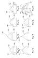
- FIGS. 7 a through 7 gdisclose various possible embodiments comprising different combinations of tapered surface 500 and pointed geometries 700 .
- FIG. 7 aillustrates the pointed geometry with a concave side 750 and a continuous convex substrate geometry 751 at the interface 500 .
- FIG. 7 bcomprises an embodiment of a thicker super hard material 752 from the apex to the non-planar interface, while still maintaining this radius of 0.075 to 0.125 inches at the apex.
- FIG. 7 cillustrates grooves 763 formed in the substrate to increase the strength of interface.
- FIG. 7 dillustrates a slightly concave geometry at the interface 753 with concave sides.
- FIG. 7 aillustrates the pointed geometry with a concave side 750 and a continuous convex substrate geometry 751 at the interface 500 .
- FIG. 7 bcomprises an embodiment of a thicker super hard material 752 from the apex to the non-planar interface, while still maintaining this radius of
- FIG. 7 ediscloses slightly convex sides 754 of the pointed geometry 700 while still maintaining the 0.075 to 0.125 inch radius.
- FIG. 7 fdiscloses a flat sided pointed geometry 755 .
- FIG. 7 gdiscloses concave and convex portions 757 , 756 of the substrate with a generally flatted central portion.
- the diamond working end 761may comprise a convex surface comprising different general angles at a lower portion 758 , a middle portion 759 and an upper portion 760 with respect to the central axis 762 of the tool.
- the lower portion 758 of the side surfacemay be angled at substantially 25 to 33 degrees from the central axis
- the middle portion 759which may make up a majority of the convex surface, may be angled at substantially 33 to 40 degrees from the central axis
- the upper portion 760 of the side surfacemay be angled at about 40 to 50 degrees from the central axis.
- FIG. 8discloses an embodiment of the drill bit 104 with a jack element 800 .
- the jack element 800comprises a hard surface of a least 63 HRc.
- the hard surfacemay be attached to the distal end 801 of the jack element 800 , but it may also be attached to any portion of the jack element 800 .
- the jack element 800is made of the material of at least 63 HRc.
- the jack element 800comprises tungsten carbide with polycrystalline diamond bonded to its distal end 801 .
- the distal end 801 of the jack element 800comprises a diamond or cubic boron nitride surface.
- the diamondmay be selected from group consisting of polycrystalline diamond, natural diamond, synthetic diamond, vapor deposited diamond, silicon bonded diamond, cobalt bonded diamond, thermally stable diamond, polycrystalline diamond with a cobalt concentration of 1 to 40 weight percent, infiltrated diamond, layered diamond, polished diamond, course diamond, fine diamond or combinations thereof.
- the jack element 800is made primarily from a cemented carbide with a binder concentration of 1 to 40 weight percent, preferably of cobalt.
- the working face 202 of the drill bit 104may be made of a steel, a matrix, or a carbide as well.
- the cutting elements 208 or distal end 801 of the jack element 800may also be made out of hardened steel or may comprise a coating of chromium, titanium, aluminum or combinations thereof.
- cutting elements 208such as diamond cutting elements, chip or wear in hard formations 105 when the drill bit 104 is used too aggressively.
- the jack element 800may limit the depth of cut that the drill bit 104 may achieve per rotation in hard formations 105 because the jack element 800 actually jacks the drill bit 104 thereby slowing its penetration in the unforeseen hard formations 105 .
- the formation 105may not be able to resist the weight on bit (WOB) loaded to the jack element 800 and a minimal amount of jacking may take place. But in hard formations 105 , the formation 105 may be able to resist the jack element 800 , thereby lifting the drill bit 104 as the cutting elements 208 remove a volume of the formation during each rotation. As the drill bit 104 rotates and more volume is removed by the cutting elements 208 and drilling mud, less WOB will be loaded to the cutting elements 208 and more WOB will be loaded to the jack element 800 .
- WOBweight on bit
- At least one of the cutting elements with a pointed geometrymay be in electrical communication with downhole instrumentation.
- the instrumentationmay be a transducer, a piezoelectric device, a magnetostrictive device, or a combination thereof.
- the transducermay be able to record the bit vibrations or acoustic signals downhole which may aid in identifying formation density, formation type, compressive strength of the formation, elasticity of the formation, stringers, or a combination thereof.
- FIG. 9discloses a drill bit 900 typically used in water well drilling.
- FIG. 9 adiscloses a drill bit 901 typically used in subterranean, horizontal drilling. These bits 900 , 901 , and other bits, may be consistent with the present invention.
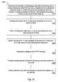
- FIG. 10is a method 1000 of an embodiment for preparing a cutting element 208 for a drill bit 104 .
- the method 1000may include the steps of providing 1001 an assembly 400 comprising a can with an opening and constituents disposed within the opening, a stop off positioned atop the constituents, a first and second lid positioned atop the constituents, a meltable sealant positioned intermediate the second lid and a cap covering the opening; heating 1002 the assembly 400 to a cleansing temperature for a first period of time; further heating 1003 the assembly 400 to a sealing temperature for a second period of time.
- the assembly 400may be heated to the cleansing temperature in a vacuum and then brought back to atmospheric pressure in an inert gas.
- the assembly 400may then be brought to the sealing temperature while in an inert gas. This may create a more stable assembly 400 because the internal pressure of the assembly 400 may be the same as the pressure out side of the assembly 400 . This type of assembly 400 may also be less prone to leaks and contamination during HPHT processing and transportation to the processing site.
- the assemblymay then be placed in a cube adapted to be placed in a chamber of a high pressure high temperature apparatus 1004 where it may undergo the HPHT process 1005 .
- the newly formed cutting element 208may be subject to grinding to remove unwanted material 1006 .
- the cutting element 208may then be brazed or welded 1007 into position on the drill bit 104 .
Landscapes
- Engineering & Computer Science (AREA)
- Life Sciences & Earth Sciences (AREA)
- Mining & Mineral Resources (AREA)
- Geology (AREA)
- Mechanical Engineering (AREA)
- Physics & Mathematics (AREA)
- Environmental & Geological Engineering (AREA)
- Fluid Mechanics (AREA)
- General Life Sciences & Earth Sciences (AREA)
- Geochemistry & Mineralogy (AREA)
- Chemical & Material Sciences (AREA)
- Crystallography & Structural Chemistry (AREA)
- Earth Drilling (AREA)
Abstract
Description
Claims (23)
Priority Applications (21)
| Application Number | Priority Date | Filing Date | Title |
|---|---|---|---|
| US11/766,975US8122980B2 (en) | 2007-06-22 | 2007-06-22 | Rotary drag bit with pointed cutting elements |
| US11/774,667US20080035389A1 (en) | 2006-08-11 | 2007-07-09 | Roof Mining Drill Bit |
| US11/829,577US8622155B2 (en) | 2006-08-11 | 2007-07-27 | Pointed diamond working ends on a shear bit |
| US11/861,641US8590644B2 (en) | 2006-08-11 | 2007-09-26 | Downhole drill bit |
| US11/871,480US7886851B2 (en) | 2006-08-11 | 2007-10-12 | Drill bit nozzle |
| US12/207,701US8240404B2 (en) | 2006-08-11 | 2008-09-10 | Roof bolt bit |
| US12/619,305US8567532B2 (en) | 2006-08-11 | 2009-11-16 | Cutting element attached to downhole fixed bladed bit at a positive rake angle |
| US12/619,466US20100059289A1 (en) | 2006-08-11 | 2009-11-16 | Cutting Element with Low Metal Concentration |
| US12/619,377US8616305B2 (en) | 2006-08-11 | 2009-11-16 | Fixed bladed bit that shifts weight between an indenter and cutting elements |
| US12/619,423US8714285B2 (en) | 2006-08-11 | 2009-11-16 | Method for drilling with a fixed bladed bit |
| US29/376,995USD674422S1 (en) | 2007-02-12 | 2010-10-15 | Drill bit with a pointed cutting element and a shearing cutting element |
| US29/376,990USD678368S1 (en) | 2007-02-12 | 2010-10-15 | Drill bit with a pointed cutting element |
| US12/915,250US8573331B2 (en) | 2006-08-11 | 2010-10-29 | Roof mining drill bit |
| US13/077,964US8191651B2 (en) | 2006-08-11 | 2011-03-31 | Sensor on a formation engaging member of a drill bit |
| US13/077,970US8596381B2 (en) | 2006-08-11 | 2011-03-31 | Sensor on a formation engaging member of a drill bit |
| US13/208,103US9316061B2 (en) | 2006-08-11 | 2011-08-11 | High impact resistant degradation element |
| US14/089,385US9051795B2 (en) | 2006-08-11 | 2013-11-25 | Downhole drill bit |
| US14/101,972US9145742B2 (en) | 2006-08-11 | 2013-12-10 | Pointed working ends on a drill bit |
| US14/717,567US9708856B2 (en) | 2006-08-11 | 2015-05-20 | Downhole drill bit |
| US14/829,037US9915102B2 (en) | 2006-08-11 | 2015-08-18 | Pointed working ends on a bit |
| US15/651,308US10378288B2 (en) | 2006-08-11 | 2017-07-17 | Downhole drill bit incorporating cutting elements of different geometries |
Applications Claiming Priority (1)
| Application Number | Priority Date | Filing Date | Title |
|---|---|---|---|
| US11/766,975US8122980B2 (en) | 2007-06-22 | 2007-06-22 | Rotary drag bit with pointed cutting elements |
Related Parent Applications (5)
| Application Number | Title | Priority Date | Filing Date |
|---|---|---|---|
| US11/695,672Continuation-In-PartUS7396086B1 (en) | 2006-08-11 | 2007-04-03 | Press-fit pick |
| US11/742,304Continuation-In-PartUS7475948B2 (en) | 2006-08-11 | 2007-04-30 | Pick with a bearing |
| US11/766,903Continuation-In-PartUS20130341999A1 (en) | 2006-08-11 | 2007-06-22 | Attack Tool with an Interruption |
| US11/774,227Continuation-In-PartUS7669938B2 (en) | 2006-08-11 | 2007-07-06 | Carbide stem press fit into a steel body of a pick |
| US11/774,227ContinuationUS7669938B2 (en) | 2006-08-11 | 2007-07-06 | Carbide stem press fit into a steel body of a pick |
Related Child Applications (6)
| Application Number | Title | Priority Date | Filing Date |
|---|---|---|---|
| US11/766,903ContinuationUS20130341999A1 (en) | 2006-08-11 | 2007-06-22 | Attack Tool with an Interruption |
| US11/773,271Continuation-In-PartUS7997661B2 (en) | 2006-08-11 | 2007-07-03 | Tapered bore in a pick |
| US11/774,667Continuation-In-PartUS20080035389A1 (en) | 2006-08-11 | 2007-07-09 | Roof Mining Drill Bit |
| US11/829,577Continuation-In-PartUS8622155B2 (en) | 2006-08-11 | 2007-07-27 | Pointed diamond working ends on a shear bit |
| US11/861,641Continuation-In-PartUS8590644B2 (en) | 2006-08-11 | 2007-09-26 | Downhole drill bit |
| US12/619,305Continuation-In-PartUS8567532B2 (en) | 2006-08-11 | 2009-11-16 | Cutting element attached to downhole fixed bladed bit at a positive rake angle |
Publications (2)
| Publication Number | Publication Date |
|---|---|
| US20080314647A1 US20080314647A1 (en) | 2008-12-25 |
| US8122980B2true US8122980B2 (en) | 2012-02-28 |
Family
ID=40135304
Family Applications (1)
| Application Number | Title | Priority Date | Filing Date |
|---|---|---|---|
| US11/766,975Active2028-04-29US8122980B2 (en) | 2006-08-11 | 2007-06-22 | Rotary drag bit with pointed cutting elements |
Country Status (1)
| Country | Link |
|---|---|
| US (1) | US8122980B2 (en) |
Cited By (10)
| Publication number | Priority date | Publication date | Assignee | Title |
|---|---|---|---|---|
| US20110266058A1 (en)* | 2010-04-28 | 2011-11-03 | Baker Hughes Incorporated | PDC Sensing Element Fabrication Process and Tool |
| US20120103688A1 (en)* | 2010-10-29 | 2012-05-03 | Baker Hughes Incorporated | Drill-Bit Seismic With Downhole Sensors |
| US9279290B2 (en) | 2012-12-28 | 2016-03-08 | Smith International, Inc. | Manufacture of cutting elements having lobes |
| US9708856B2 (en) | 2006-08-11 | 2017-07-18 | Smith International, Inc. | Downhole drill bit |
| US20170292376A1 (en)* | 2010-04-28 | 2017-10-12 | Baker Hughes Incorporated | Pdc sensing element fabrication process and tool |
| US9915102B2 (en) | 2006-08-11 | 2018-03-13 | Schlumberger Technology Corporation | Pointed working ends on a bit |
| US10590710B2 (en) | 2016-12-09 | 2020-03-17 | Baker Hughes, A Ge Company, Llc | Cutting elements, earth-boring tools including the cutting elements, and methods of forming the cutting elements |
| US11015397B2 (en) | 2014-12-31 | 2021-05-25 | Schlumberger Technology Corporation | Cutting elements and drill bits incorporating the same |
| US11091960B2 (en)* | 2015-12-18 | 2021-08-17 | Schlumberger Technology Corporation | Placement of non-planar cutting elements |
| US11828108B2 (en) | 2016-01-13 | 2023-11-28 | Schlumberger Technology Corporation | Angled chisel insert |
Families Citing this family (18)
| Publication number | Priority date | Publication date | Assignee | Title |
|---|---|---|---|---|
| US7635035B1 (en) | 2005-08-24 | 2009-12-22 | Us Synthetic Corporation | Polycrystalline diamond compact (PDC) cutting element having multiple catalytic elements |
| US9103172B1 (en) | 2005-08-24 | 2015-08-11 | Us Synthetic Corporation | Polycrystalline diamond compact including a pre-sintered polycrystalline diamond table including a nonmetallic catalyst that limits infiltration of a metallic-catalyst infiltrant therein and applications therefor |
| US8734552B1 (en) | 2005-08-24 | 2014-05-27 | Us Synthetic Corporation | Methods of fabricating polycrystalline diamond and polycrystalline diamond compacts with a carbonate material |
| US8459357B2 (en)* | 2009-05-04 | 2013-06-11 | Smith International, Inc. | Milling system and method of milling |
| US8505634B2 (en)* | 2009-12-28 | 2013-08-13 | Baker Hughes Incorporated | Earth-boring tools having differing cutting elements on a blade and related methods |
| US8794356B2 (en)* | 2010-02-05 | 2014-08-05 | Baker Hughes Incorporated | Shaped cutting elements on drill bits and other earth-boring tools, and methods of forming same |
| US8418784B2 (en) | 2010-05-11 | 2013-04-16 | David R. Hall | Central cutting region of a drilling head assembly |
| US8851207B2 (en) | 2011-05-05 | 2014-10-07 | Baker Hughes Incorporated | Earth-boring tools and methods of forming such earth-boring tools |
| SA111320671B1 (en) | 2010-08-06 | 2015-01-22 | بيكر هوغيس انكور | Shaped cutting elements for earth boring tools, earth boring tools including such cutting elements, and related methods |
| CN103842607B (en) | 2011-02-10 | 2016-08-31 | 史密斯运输股份有限公司 | Cutting hybrid bits and other downhole cutting tools |
| RU2589786C2 (en) | 2011-06-22 | 2016-07-10 | Смит Интернэшнл, Инк. | Drill bit with fixed cutters with elements for producing fragments of core |
| US9500070B2 (en)* | 2011-09-19 | 2016-11-22 | Baker Hughes Incorporated | Sensor-enabled cutting elements for earth-boring tools, earth-boring tools so equipped, and related methods |
| US9212523B2 (en) | 2011-12-01 | 2015-12-15 | Smith International, Inc. | Drill bit having geometrically sharp inserts |
| EP2812523B1 (en) | 2012-02-08 | 2019-08-07 | Baker Hughes, a GE company, LLC | Shaped cutting elements for earth-boring tools and earth-boring tools including such cutting elements |
| US9404310B1 (en)* | 2012-03-01 | 2016-08-02 | Us Synthetic Corporation | Polycrystalline diamond compacts including a domed polycrystalline diamond table, and applications therefor |
| CN111594134B (en)* | 2020-06-10 | 2022-08-02 | 西南石油大学 | An intelligent drill bit for real-time monitoring of drilling cutting force and its working method |
| US12270254B2 (en)* | 2020-10-19 | 2025-04-08 | Taurex Drill Bits, LLC | Drill bits with variable cutter alignment |
| USD1034722S1 (en)* | 2024-03-27 | 2024-07-09 | Yuanguo Cheng | PVC pipe reamer |
Citations (131)
| Publication number | Priority date | Publication date | Assignee | Title |
|---|---|---|---|---|
| US465103A (en) | 1891-12-15 | Combined drill | ||
| US616118A (en) | 1898-12-20 | Ernest kuhne | ||
| US946060A (en) | 1908-10-10 | 1910-01-11 | David W Looker | Post-hole auger. |
| US1116154A (en) | 1913-03-26 | 1914-11-03 | William G Stowers | Post-hole digger. |
| US1183630A (en) | 1915-06-29 | 1916-05-16 | Charles R Bryson | Underreamer. |
| US1189560A (en) | 1914-07-11 | 1916-07-04 | Georg Gondos | Rotary drill. |
| US1360908A (en) | 1920-07-16 | 1920-11-30 | Everson August | Reamer |
| US1387733A (en) | 1921-02-15 | 1921-08-16 | Penelton G Midgett | Well-drilling bit |
| US1460671A (en) | 1920-06-17 | 1923-07-03 | Hebsacker Wilhelm | Excavating machine |
| US1544757A (en) | 1923-02-05 | 1925-07-07 | Hufford | Oil-well reamer |
| US1821474A (en) | 1927-12-05 | 1931-09-01 | Sullivan Machinery Co | Boring tool |
| US1879177A (en) | 1930-05-16 | 1932-09-27 | W J Newman Company | Drilling apparatus for large wells |
| US2054255A (en) | 1934-11-13 | 1936-09-15 | John H Howard | Well drilling tool |
| US2064255A (en) | 1936-06-19 | 1936-12-15 | Hughes Tool Co | Removable core breaker |
| US2169223A (en) | 1937-04-10 | 1939-08-15 | Carl C Christian | Drilling apparatus |
| US2218130A (en) | 1938-06-14 | 1940-10-15 | Shell Dev | Hydraulic disruption of solids |
| US2320136A (en) | 1940-09-30 | 1943-05-25 | Archer W Kammerer | Well drilling bit |
| US2466991A (en) | 1945-06-06 | 1949-04-12 | Archer W Kammerer | Rotary drill bit |
| US2540464A (en) | 1947-05-31 | 1951-02-06 | Reed Roller Bit Co | Pilot bit |
| US2755071A (en) | 1954-08-25 | 1956-07-17 | Rotary Oil Tool Company | Apparatus for enlarging well bores |
| US2776819A (en) | 1953-10-09 | 1957-01-08 | Philip B Brown | Rock drill bit |
| US2819043A (en) | 1955-06-13 | 1958-01-07 | Homer I Henderson | Combination drilling bit |
| US2838284A (en) | 1956-04-19 | 1958-06-10 | Christensen Diamond Prod Co | Rotary drill bit |
| US2894722A (en) | 1953-03-17 | 1959-07-14 | Ralph Q Buttolph | Method and apparatus for providing a well bore with a deflected extension |
| US2901223A (en) | 1955-11-30 | 1959-08-25 | Hughes Tool Co | Earth boring drill |
| US2963102A (en) | 1956-08-13 | 1960-12-06 | James E Smith | Hydraulic drill bit |
| US3135341A (en) | 1960-10-04 | 1964-06-02 | Christensen Diamond Prod Co | Diamond drill bits |
| US3294186A (en) | 1964-06-22 | 1966-12-27 | Tartan Ind Inc | Rock bits and methods of making the same |
| US3301339A (en) | 1964-06-19 | 1967-01-31 | Exxon Production Research Co | Drill bit with wear resistant material on blade |
| US3379264A (en) | 1964-11-05 | 1968-04-23 | Dravo Corp | Earth boring machine |
| US3429390A (en) | 1967-05-19 | 1969-02-25 | Supercussion Drills Inc | Earth-drilling bits |
| US3493165A (en) | 1966-11-18 | 1970-02-03 | Georg Schonfeld | Continuous tunnel borer |
| US3583504A (en) | 1969-02-24 | 1971-06-08 | Mission Mfg Co | Gauge cutting bit |
| US3764493A (en) | 1972-08-31 | 1973-10-09 | Us Interior | Recovery of nickel and cobalt |
| US3821993A (en) | 1971-09-07 | 1974-07-02 | Kennametal Inc | Auger arrangement |
| US3955635A (en) | 1975-02-03 | 1976-05-11 | Skidmore Sam C | Percussion drill bit |
| US3960223A (en) | 1974-03-26 | 1976-06-01 | Gebrueder Heller | Drill for rock |
| US4081042A (en) | 1976-07-08 | 1978-03-28 | Tri-State Oil Tool Industries, Inc. | Stabilizer and rotary expansible drill bit apparatus |
| US4096917A (en) | 1975-09-29 | 1978-06-27 | Harris Jesse W | Earth drilling knobby bit |
| US4106577A (en) | 1977-06-20 | 1978-08-15 | The Curators Of The University Of Missouri | Hydromechanical drilling device |
| US4109737A (en) | 1976-06-24 | 1978-08-29 | General Electric Company | Rotary drill bit |
| US4176723A (en) | 1977-11-11 | 1979-12-04 | DTL, Incorporated | Diamond drill bit |
| US4253533A (en) | 1979-11-05 | 1981-03-03 | Smith International, Inc. | Variable wear pad for crossflow drag bit |
| US4280573A (en) | 1979-06-13 | 1981-07-28 | Sudnishnikov Boris V | Rock-breaking tool for percussive-action machines |
| US4304312A (en) | 1980-01-11 | 1981-12-08 | Sandvik Aktiebolag | Percussion drill bit having centrally projecting insert |
| US4307786A (en) | 1978-07-27 | 1981-12-29 | Evans Robert F | Borehole angle control by gage corner removal effects from hydraulic fluid jet |
| US4397361A (en) | 1981-06-01 | 1983-08-09 | Dresser Industries, Inc. | Abradable cutter protection |
| US4416339A (en) | 1982-01-21 | 1983-11-22 | Baker Royce E | Bit guidance device and method |
| US4445580A (en) | 1979-06-19 | 1984-05-01 | Syndrill Carbide Diamond Company | Deep hole rock drill bit |
| US4448269A (en) | 1981-10-27 | 1984-05-15 | Hitachi Construction Machinery Co., Ltd. | Cutter head for pit-boring machine |
| US4499795A (en) | 1983-09-23 | 1985-02-19 | Strata Bit Corporation | Method of drill bit manufacture |
| US4531592A (en) | 1983-02-07 | 1985-07-30 | Asadollah Hayatdavoudi | Jet nozzle |
| US4535853A (en) | 1982-12-23 | 1985-08-20 | Charbonnages De France | Drill bit for jet assisted rotary drilling |
| US4538691A (en) | 1984-01-30 | 1985-09-03 | Strata Bit Corporation | Rotary drill bit |
| US4566545A (en) | 1983-09-29 | 1986-01-28 | Norton Christensen, Inc. | Coring device with an improved core sleeve and anti-gripping collar with a collective core catcher |
| US4574895A (en) | 1982-02-22 | 1986-03-11 | Hughes Tool Company - Usa | Solid head bit with tungsten carbide central core |
| US4640374A (en) | 1984-01-30 | 1987-02-03 | Strata Bit Corporation | Rotary drill bit |
| US4852672A (en) | 1988-08-15 | 1989-08-01 | Behrens Robert N | Drill apparatus having a primary drill and a pilot drill |
| US4889017A (en) | 1984-07-19 | 1989-12-26 | Reed Tool Co., Ltd. | Rotary drill bit for use in drilling holes in subsurface earth formations |
| US4962822A (en) | 1989-12-15 | 1990-10-16 | Numa Tool Company | Downhole drill bit and bit coupling |
| US4981184A (en) | 1988-11-21 | 1991-01-01 | Smith International, Inc. | Diamond drag bit for soft formations |
| US5009273A (en) | 1988-01-08 | 1991-04-23 | Foothills Diamond Coring (1980) Ltd. | Deflection apparatus |
| US5027914A (en) | 1990-06-04 | 1991-07-02 | Wilson Steve B | Pilot casing mill |
| US5038873A (en) | 1989-04-13 | 1991-08-13 | Baker Hughes Incorporated | Drilling tool with retractable pilot drilling unit |
| US5119892A (en) | 1989-11-25 | 1992-06-09 | Reed Tool Company Limited | Notary drill bits |
| US5141063A (en) | 1990-08-08 | 1992-08-25 | Quesenbury Jimmy B | Restriction enhancement drill |
| US5186268A (en) | 1991-10-31 | 1993-02-16 | Camco Drilling Group Ltd. | Rotary drill bits |
| US5222566A (en) | 1991-02-01 | 1993-06-29 | Camco Drilling Group Ltd. | Rotary drill bits and methods of designing such drill bits |
| US5255749A (en) | 1992-03-16 | 1993-10-26 | Steer-Rite, Ltd. | Steerable burrowing mole |
| US5265682A (en) | 1991-06-25 | 1993-11-30 | Camco Drilling Group Limited | Steerable rotary drilling systems |
| US5332051A (en)* | 1991-10-09 | 1994-07-26 | Smith International, Inc. | Optimized PDC cutting shape |
| US5361859A (en) | 1993-02-12 | 1994-11-08 | Baker Hughes Incorporated | Expandable gage bit for drilling and method of drilling |
| US5410303A (en) | 1991-05-15 | 1995-04-25 | Baroid Technology, Inc. | System for drilling deivated boreholes |
| US5417292A (en) | 1993-11-22 | 1995-05-23 | Polakoff; Paul | Large diameter rock drill |
| US5423389A (en) | 1994-03-25 | 1995-06-13 | Amoco Corporation | Curved drilling apparatus |
| US5507357A (en) | 1994-02-04 | 1996-04-16 | Foremost Industries, Inc. | Pilot bit for use in auger bit assembly |
| US5535839A (en)* | 1995-06-07 | 1996-07-16 | Brady; William J. | Roof drill bit with radial domed PCD inserts |
| US5560440A (en) | 1993-02-12 | 1996-10-01 | Baker Hughes Incorporated | Bit for subterranean drilling fabricated from separately-formed major components |
| US5568838A (en) | 1994-09-23 | 1996-10-29 | Baker Hughes Incorporated | Bit-stabilized combination coring and drilling system |
| US5655614A (en) | 1994-12-20 | 1997-08-12 | Smith International, Inc. | Self-centering polycrystalline diamond cutting rock bit |
| US5678644A (en) | 1995-08-15 | 1997-10-21 | Diamond Products International, Inc. | Bi-center and bit method for enhancing stability |
| US5732784A (en)* | 1996-07-25 | 1998-03-31 | Nelson; Jack R. | Cutting means for drag drill bits |
| US5794728A (en) | 1995-06-20 | 1998-08-18 | Sandvik Ab | Percussion rock drill bit |
| US5848657A (en) | 1996-12-27 | 1998-12-15 | General Electric Company | Polycrystalline diamond cutting element |
| US5896938A (en) | 1995-12-01 | 1999-04-27 | Tetra Corporation | Portable electrohydraulic mining drill |
| US5947215A (en) | 1997-11-06 | 1999-09-07 | Sandvik Ab | Diamond enhanced rock drill bit for percussive drilling |
| US5950743A (en) | 1997-02-05 | 1999-09-14 | Cox; David M. | Method for horizontal directional drilling of rock formations |
| US5957223A (en) | 1997-03-05 | 1999-09-28 | Baker Hughes Incorporated | Bi-center drill bit with enhanced stabilizing features |
| US5957225A (en) | 1997-07-31 | 1999-09-28 | Bp Amoco Corporation | Drilling assembly and method of drilling for unstable and depleted formations |
| US5967247A (en) | 1997-09-08 | 1999-10-19 | Baker Hughes Incorporated | Steerable rotary drag bit with longitudinally variable gage aggressiveness |
| US5979571A (en) | 1996-09-27 | 1999-11-09 | Baker Hughes Incorporated | Combination milling tool and drill bit |
| US5992548A (en) | 1995-08-15 | 1999-11-30 | Diamond Products International, Inc. | Bi-center bit with oppositely disposed cutting surfaces |
| US5992547A (en) | 1995-10-10 | 1999-11-30 | Camco International (Uk) Limited | Rotary drill bits |
| US6003623A (en)* | 1998-04-24 | 1999-12-21 | Dresser Industries, Inc. | Cutters and bits for terrestrial boring |
| US6021859A (en) | 1993-12-09 | 2000-02-08 | Baker Hughes Incorporated | Stress related placement of engineered superabrasive cutting elements on rotary drag bits |
| US6039131A (en) | 1997-08-25 | 2000-03-21 | Smith International, Inc. | Directional drift and drill PDC drill bit |
| US6131675A (en) | 1998-09-08 | 2000-10-17 | Baker Hughes Incorporated | Combination mill and drill bit |
| US6150822A (en) | 1994-01-21 | 2000-11-21 | Atlantic Richfield Company | Sensor in bit for measuring formation properties while drilling |
| US6186251B1 (en) | 1998-07-27 | 2001-02-13 | Baker Hughes Incorporated | Method of altering a balance characteristic and moment configuration of a drill bit and drill bit |
| US6199645B1 (en)* | 1998-02-13 | 2001-03-13 | Smith International, Inc. | Engineered enhanced inserts for rock drilling bits |
| US6202761B1 (en) | 1998-04-30 | 2001-03-20 | Goldrus Producing Company | Directional drilling method and apparatus |
| US6213226B1 (en) | 1997-12-04 | 2001-04-10 | Halliburton Energy Services, Inc. | Directional drilling assembly and method |
| US6223824B1 (en) | 1996-06-17 | 2001-05-01 | Weatherford/Lamb, Inc. | Downhole apparatus |
| US20010004946A1 (en) | 1997-11-28 | 2001-06-28 | Kenneth M. Jensen | Enhanced non-planar drill insert |
| US6269893B1 (en) | 1999-06-30 | 2001-08-07 | Smith International, Inc. | Bi-centered drill bit having improved drilling stability mud hydraulics and resistance to cutter damage |
| US6290007B2 (en)* | 1997-09-08 | 2001-09-18 | Baker Hughes Incorporated | Rotary drill bits for directional drilling employing tandem gage pad arrangement with cutting elements and up-drill capability |
| US20010040053A1 (en) | 1997-09-08 | 2001-11-15 | Beuershausen Christopher C. | Multi-aggressiveness cutting face on PDC cutters and method of drilling subterranean formations |
| US6332503B1 (en) | 1992-01-31 | 2001-12-25 | Baker Hughes Incorporated | Fixed cutter bit with chisel or vertical cutting elements |
| US6340064B2 (en) | 1999-02-03 | 2002-01-22 | Diamond Products International, Inc. | Bi-center bit adapted to drill casing shoe |
| US6364034B1 (en) | 2000-02-08 | 2002-04-02 | William N Schoeffler | Directional drilling apparatus |
| US6394200B1 (en) | 1999-10-28 | 2002-05-28 | Camco International (U.K.) Limited | Drillout bi-center bit |
| US6408959B2 (en) | 1998-09-18 | 2002-06-25 | Kenneth E. Bertagnolli | Polycrystalline diamond compact cutter having a stress mitigating hoop at the periphery |
| US6439326B1 (en) | 2000-04-10 | 2002-08-27 | Smith International, Inc. | Centered-leg roller cone drill bit |
| US6474425B1 (en) | 2000-07-19 | 2002-11-05 | Smith International, Inc. | Asymmetric diamond impregnated drill bit |
| US6484825B2 (en) | 2001-01-27 | 2002-11-26 | Camco International (Uk) Limited | Cutting structure for earth boring drill bits |
| US6510906B1 (en) | 1999-11-29 | 2003-01-28 | Baker Hughes Incorporated | Impregnated bit with PDC cutters in cone area |
| US6513606B1 (en) | 1998-11-10 | 2003-02-04 | Baker Hughes Incorporated | Self-controlled directional drilling systems and methods |
| US6533050B2 (en) | 1996-02-27 | 2003-03-18 | Anthony Molloy | Excavation bit for a drilling apparatus |
| US6594881B2 (en) | 1997-03-21 | 2003-07-22 | Baker Hughes Incorporated | Bit torque limiting device |
| US6601454B1 (en) | 2001-10-02 | 2003-08-05 | Ted R. Botnan | Apparatus for testing jack legs and air drills |
| US6622803B2 (en) | 2000-03-22 | 2003-09-23 | Rotary Drilling Technology, Llc | Stabilizer for use in a drill string |
| US20030213621A1 (en) | 2002-03-25 | 2003-11-20 | Werner Britten | Guide assembly for a core bit |
| US6668949B1 (en) | 1999-10-21 | 2003-12-30 | Allen Kent Rives | Underreamer and method of use |
| US6729420B2 (en) | 2002-03-25 | 2004-05-04 | Smith International, Inc. | Multi profile performance enhancing centric bit and method of bit design |
| US6732817B2 (en) | 2002-02-19 | 2004-05-11 | Smith International, Inc. | Expandable underreamer/stabilizer |
| US6822579B2 (en) | 2001-05-09 | 2004-11-23 | Schlumberger Technology Corporation | Steerable transceiver unit for downhole data acquistion in a formation |
| US20040238221A1 (en) | 2001-07-16 | 2004-12-02 | Runia Douwe Johannes | Steerable rotary drill bit assembly with pilot bit |
| US20040256155A1 (en) | 2001-09-20 | 2004-12-23 | Kriesels Petrus Cornelis | Percussion drilling head |
| US6929076B2 (en) | 2002-10-04 | 2005-08-16 | Security Dbs Nv/Sa | Bore hole underreamer having extendible cutting arms |
| US6953096B2 (en) | 2002-12-31 | 2005-10-11 | Weatherford/Lamb, Inc. | Expandable bit with secondary release device |
| US20060086537A1 (en)* | 2002-12-19 | 2006-04-27 | Halliburton Energy Services, Inc. | Drilling with mixed tooth types |
Family Cites Families (2)
| Publication number | Priority date | Publication date | Assignee | Title |
|---|---|---|---|---|
| US2933102A (en)* | 1957-09-19 | 1960-04-19 | North American Aviation Inc | Environment excluding vent plug |
| US4538681A (en)* | 1984-12-13 | 1985-09-03 | Camco, Incorporated | Soft set and pull latch and setting tool for a well measuring instrument |
- 2007
- 2007-06-22USUS11/766,975patent/US8122980B2/enactiveActive
Patent Citations (133)
| Publication number | Priority date | Publication date | Assignee | Title |
|---|---|---|---|---|
| US465103A (en) | 1891-12-15 | Combined drill | ||
| US616118A (en) | 1898-12-20 | Ernest kuhne | ||
| US946060A (en) | 1908-10-10 | 1910-01-11 | David W Looker | Post-hole auger. |
| US1116154A (en) | 1913-03-26 | 1914-11-03 | William G Stowers | Post-hole digger. |
| US1189560A (en) | 1914-07-11 | 1916-07-04 | Georg Gondos | Rotary drill. |
| US1183630A (en) | 1915-06-29 | 1916-05-16 | Charles R Bryson | Underreamer. |
| US1460671A (en) | 1920-06-17 | 1923-07-03 | Hebsacker Wilhelm | Excavating machine |
| US1360908A (en) | 1920-07-16 | 1920-11-30 | Everson August | Reamer |
| US1387733A (en) | 1921-02-15 | 1921-08-16 | Penelton G Midgett | Well-drilling bit |
| US1544757A (en) | 1923-02-05 | 1925-07-07 | Hufford | Oil-well reamer |
| US1821474A (en) | 1927-12-05 | 1931-09-01 | Sullivan Machinery Co | Boring tool |
| US1879177A (en) | 1930-05-16 | 1932-09-27 | W J Newman Company | Drilling apparatus for large wells |
| US2054255A (en) | 1934-11-13 | 1936-09-15 | John H Howard | Well drilling tool |
| US2064255A (en) | 1936-06-19 | 1936-12-15 | Hughes Tool Co | Removable core breaker |
| US2169223A (en) | 1937-04-10 | 1939-08-15 | Carl C Christian | Drilling apparatus |
| US2218130A (en) | 1938-06-14 | 1940-10-15 | Shell Dev | Hydraulic disruption of solids |
| US2320136A (en) | 1940-09-30 | 1943-05-25 | Archer W Kammerer | Well drilling bit |
| US2466991A (en) | 1945-06-06 | 1949-04-12 | Archer W Kammerer | Rotary drill bit |
| US2540464A (en) | 1947-05-31 | 1951-02-06 | Reed Roller Bit Co | Pilot bit |
| US2894722A (en) | 1953-03-17 | 1959-07-14 | Ralph Q Buttolph | Method and apparatus for providing a well bore with a deflected extension |
| US2776819A (en) | 1953-10-09 | 1957-01-08 | Philip B Brown | Rock drill bit |
| US2755071A (en) | 1954-08-25 | 1956-07-17 | Rotary Oil Tool Company | Apparatus for enlarging well bores |
| US2819043A (en) | 1955-06-13 | 1958-01-07 | Homer I Henderson | Combination drilling bit |
| US2901223A (en) | 1955-11-30 | 1959-08-25 | Hughes Tool Co | Earth boring drill |
| US2838284A (en) | 1956-04-19 | 1958-06-10 | Christensen Diamond Prod Co | Rotary drill bit |
| US2963102A (en) | 1956-08-13 | 1960-12-06 | James E Smith | Hydraulic drill bit |
| US3135341A (en) | 1960-10-04 | 1964-06-02 | Christensen Diamond Prod Co | Diamond drill bits |
| US3301339A (en) | 1964-06-19 | 1967-01-31 | Exxon Production Research Co | Drill bit with wear resistant material on blade |
| US3294186A (en) | 1964-06-22 | 1966-12-27 | Tartan Ind Inc | Rock bits and methods of making the same |
| US3379264A (en) | 1964-11-05 | 1968-04-23 | Dravo Corp | Earth boring machine |
| US3493165A (en) | 1966-11-18 | 1970-02-03 | Georg Schonfeld | Continuous tunnel borer |
| US3429390A (en) | 1967-05-19 | 1969-02-25 | Supercussion Drills Inc | Earth-drilling bits |
| US3583504A (en) | 1969-02-24 | 1971-06-08 | Mission Mfg Co | Gauge cutting bit |
| US3821993A (en) | 1971-09-07 | 1974-07-02 | Kennametal Inc | Auger arrangement |
| US3764493A (en) | 1972-08-31 | 1973-10-09 | Us Interior | Recovery of nickel and cobalt |
| US3960223A (en) | 1974-03-26 | 1976-06-01 | Gebrueder Heller | Drill for rock |
| US3955635A (en) | 1975-02-03 | 1976-05-11 | Skidmore Sam C | Percussion drill bit |
| US4096917A (en) | 1975-09-29 | 1978-06-27 | Harris Jesse W | Earth drilling knobby bit |
| US4109737A (en) | 1976-06-24 | 1978-08-29 | General Electric Company | Rotary drill bit |
| US4081042A (en) | 1976-07-08 | 1978-03-28 | Tri-State Oil Tool Industries, Inc. | Stabilizer and rotary expansible drill bit apparatus |
| US4106577A (en) | 1977-06-20 | 1978-08-15 | The Curators Of The University Of Missouri | Hydromechanical drilling device |
| US4176723A (en) | 1977-11-11 | 1979-12-04 | DTL, Incorporated | Diamond drill bit |
| US4307786A (en) | 1978-07-27 | 1981-12-29 | Evans Robert F | Borehole angle control by gage corner removal effects from hydraulic fluid jet |
| US4280573A (en) | 1979-06-13 | 1981-07-28 | Sudnishnikov Boris V | Rock-breaking tool for percussive-action machines |
| US4445580A (en) | 1979-06-19 | 1984-05-01 | Syndrill Carbide Diamond Company | Deep hole rock drill bit |
| US4253533A (en) | 1979-11-05 | 1981-03-03 | Smith International, Inc. | Variable wear pad for crossflow drag bit |
| US4304312A (en) | 1980-01-11 | 1981-12-08 | Sandvik Aktiebolag | Percussion drill bit having centrally projecting insert |
| US4397361A (en) | 1981-06-01 | 1983-08-09 | Dresser Industries, Inc. | Abradable cutter protection |
| US4448269A (en) | 1981-10-27 | 1984-05-15 | Hitachi Construction Machinery Co., Ltd. | Cutter head for pit-boring machine |
| US4416339A (en) | 1982-01-21 | 1983-11-22 | Baker Royce E | Bit guidance device and method |
| US4574895A (en) | 1982-02-22 | 1986-03-11 | Hughes Tool Company - Usa | Solid head bit with tungsten carbide central core |
| US4535853A (en) | 1982-12-23 | 1985-08-20 | Charbonnages De France | Drill bit for jet assisted rotary drilling |
| US4531592A (en) | 1983-02-07 | 1985-07-30 | Asadollah Hayatdavoudi | Jet nozzle |
| US4499795A (en) | 1983-09-23 | 1985-02-19 | Strata Bit Corporation | Method of drill bit manufacture |
| US4566545A (en) | 1983-09-29 | 1986-01-28 | Norton Christensen, Inc. | Coring device with an improved core sleeve and anti-gripping collar with a collective core catcher |
| US4538691A (en) | 1984-01-30 | 1985-09-03 | Strata Bit Corporation | Rotary drill bit |
| US4640374A (en) | 1984-01-30 | 1987-02-03 | Strata Bit Corporation | Rotary drill bit |
| US4889017A (en) | 1984-07-19 | 1989-12-26 | Reed Tool Co., Ltd. | Rotary drill bit for use in drilling holes in subsurface earth formations |
| US5009273A (en) | 1988-01-08 | 1991-04-23 | Foothills Diamond Coring (1980) Ltd. | Deflection apparatus |
| US4852672A (en) | 1988-08-15 | 1989-08-01 | Behrens Robert N | Drill apparatus having a primary drill and a pilot drill |
| US4981184A (en) | 1988-11-21 | 1991-01-01 | Smith International, Inc. | Diamond drag bit for soft formations |
| US5038873A (en) | 1989-04-13 | 1991-08-13 | Baker Hughes Incorporated | Drilling tool with retractable pilot drilling unit |
| US5119892A (en) | 1989-11-25 | 1992-06-09 | Reed Tool Company Limited | Notary drill bits |
| US4962822A (en) | 1989-12-15 | 1990-10-16 | Numa Tool Company | Downhole drill bit and bit coupling |
| US5027914A (en) | 1990-06-04 | 1991-07-02 | Wilson Steve B | Pilot casing mill |
| US5141063A (en) | 1990-08-08 | 1992-08-25 | Quesenbury Jimmy B | Restriction enhancement drill |
| US5222566A (en) | 1991-02-01 | 1993-06-29 | Camco Drilling Group Ltd. | Rotary drill bits and methods of designing such drill bits |
| US5410303A (en) | 1991-05-15 | 1995-04-25 | Baroid Technology, Inc. | System for drilling deivated boreholes |
| US5265682A (en) | 1991-06-25 | 1993-11-30 | Camco Drilling Group Limited | Steerable rotary drilling systems |
| US5332051A (en)* | 1991-10-09 | 1994-07-26 | Smith International, Inc. | Optimized PDC cutting shape |
| US5186268A (en) | 1991-10-31 | 1993-02-16 | Camco Drilling Group Ltd. | Rotary drill bits |
| US6332503B1 (en) | 1992-01-31 | 2001-12-25 | Baker Hughes Incorporated | Fixed cutter bit with chisel or vertical cutting elements |
| US5255749A (en) | 1992-03-16 | 1993-10-26 | Steer-Rite, Ltd. | Steerable burrowing mole |
| US5560440A (en) | 1993-02-12 | 1996-10-01 | Baker Hughes Incorporated | Bit for subterranean drilling fabricated from separately-formed major components |
| US5361859A (en) | 1993-02-12 | 1994-11-08 | Baker Hughes Incorporated | Expandable gage bit for drilling and method of drilling |
| US5417292A (en) | 1993-11-22 | 1995-05-23 | Polakoff; Paul | Large diameter rock drill |
| US6021859A (en) | 1993-12-09 | 2000-02-08 | Baker Hughes Incorporated | Stress related placement of engineered superabrasive cutting elements on rotary drag bits |
| US6150822A (en) | 1994-01-21 | 2000-11-21 | Atlantic Richfield Company | Sensor in bit for measuring formation properties while drilling |
| US5507357A (en) | 1994-02-04 | 1996-04-16 | Foremost Industries, Inc. | Pilot bit for use in auger bit assembly |
| US5423389A (en) | 1994-03-25 | 1995-06-13 | Amoco Corporation | Curved drilling apparatus |
| US5568838A (en) | 1994-09-23 | 1996-10-29 | Baker Hughes Incorporated | Bit-stabilized combination coring and drilling system |
| US5655614A (en) | 1994-12-20 | 1997-08-12 | Smith International, Inc. | Self-centering polycrystalline diamond cutting rock bit |
| US5535839A (en)* | 1995-06-07 | 1996-07-16 | Brady; William J. | Roof drill bit with radial domed PCD inserts |
| US5794728A (en) | 1995-06-20 | 1998-08-18 | Sandvik Ab | Percussion rock drill bit |
| US5678644A (en) | 1995-08-15 | 1997-10-21 | Diamond Products International, Inc. | Bi-center and bit method for enhancing stability |
| US5992548A (en) | 1995-08-15 | 1999-11-30 | Diamond Products International, Inc. | Bi-center bit with oppositely disposed cutting surfaces |
| US5992547A (en) | 1995-10-10 | 1999-11-30 | Camco International (Uk) Limited | Rotary drill bits |
| US5896938A (en) | 1995-12-01 | 1999-04-27 | Tetra Corporation | Portable electrohydraulic mining drill |
| US6533050B2 (en) | 1996-02-27 | 2003-03-18 | Anthony Molloy | Excavation bit for a drilling apparatus |
| US6223824B1 (en) | 1996-06-17 | 2001-05-01 | Weatherford/Lamb, Inc. | Downhole apparatus |
| US5732784A (en)* | 1996-07-25 | 1998-03-31 | Nelson; Jack R. | Cutting means for drag drill bits |
| US5979571A (en) | 1996-09-27 | 1999-11-09 | Baker Hughes Incorporated | Combination milling tool and drill bit |
| US5848657A (en) | 1996-12-27 | 1998-12-15 | General Electric Company | Polycrystalline diamond cutting element |
| US5950743A (en) | 1997-02-05 | 1999-09-14 | Cox; David M. | Method for horizontal directional drilling of rock formations |
| US5957223A (en) | 1997-03-05 | 1999-09-28 | Baker Hughes Incorporated | Bi-center drill bit with enhanced stabilizing features |
| US6594881B2 (en) | 1997-03-21 | 2003-07-22 | Baker Hughes Incorporated | Bit torque limiting device |
| US5957225A (en) | 1997-07-31 | 1999-09-28 | Bp Amoco Corporation | Drilling assembly and method of drilling for unstable and depleted formations |
| US6039131A (en) | 1997-08-25 | 2000-03-21 | Smith International, Inc. | Directional drift and drill PDC drill bit |
| US5967247A (en) | 1997-09-08 | 1999-10-19 | Baker Hughes Incorporated | Steerable rotary drag bit with longitudinally variable gage aggressiveness |
| US6672406B2 (en) | 1997-09-08 | 2004-01-06 | Baker Hughes Incorporated | Multi-aggressiveness cuttting face on PDC cutters and method of drilling subterranean formations |
| US20010040053A1 (en) | 1997-09-08 | 2001-11-15 | Beuershausen Christopher C. | Multi-aggressiveness cutting face on PDC cutters and method of drilling subterranean formations |
| US6290007B2 (en)* | 1997-09-08 | 2001-09-18 | Baker Hughes Incorporated | Rotary drill bits for directional drilling employing tandem gage pad arrangement with cutting elements and up-drill capability |
| US5947215A (en) | 1997-11-06 | 1999-09-07 | Sandvik Ab | Diamond enhanced rock drill bit for percussive drilling |
| US20010004946A1 (en) | 1997-11-28 | 2001-06-28 | Kenneth M. Jensen | Enhanced non-planar drill insert |
| US6213226B1 (en) | 1997-12-04 | 2001-04-10 | Halliburton Energy Services, Inc. | Directional drilling assembly and method |
| US6199645B1 (en)* | 1998-02-13 | 2001-03-13 | Smith International, Inc. | Engineered enhanced inserts for rock drilling bits |
| US6484826B1 (en) | 1998-02-13 | 2002-11-26 | Smith International, Inc. | Engineered enhanced inserts for rock drilling bits |
| US6003623A (en)* | 1998-04-24 | 1999-12-21 | Dresser Industries, Inc. | Cutters and bits for terrestrial boring |
| US6202761B1 (en) | 1998-04-30 | 2001-03-20 | Goldrus Producing Company | Directional drilling method and apparatus |
| US6186251B1 (en) | 1998-07-27 | 2001-02-13 | Baker Hughes Incorporated | Method of altering a balance characteristic and moment configuration of a drill bit and drill bit |
| US6131675A (en) | 1998-09-08 | 2000-10-17 | Baker Hughes Incorporated | Combination mill and drill bit |
| US6408959B2 (en) | 1998-09-18 | 2002-06-25 | Kenneth E. Bertagnolli | Polycrystalline diamond compact cutter having a stress mitigating hoop at the periphery |
| US6513606B1 (en) | 1998-11-10 | 2003-02-04 | Baker Hughes Incorporated | Self-controlled directional drilling systems and methods |
| US6340064B2 (en) | 1999-02-03 | 2002-01-22 | Diamond Products International, Inc. | Bi-center bit adapted to drill casing shoe |
| US6269893B1 (en) | 1999-06-30 | 2001-08-07 | Smith International, Inc. | Bi-centered drill bit having improved drilling stability mud hydraulics and resistance to cutter damage |
| US6668949B1 (en) | 1999-10-21 | 2003-12-30 | Allen Kent Rives | Underreamer and method of use |
| US6394200B1 (en) | 1999-10-28 | 2002-05-28 | Camco International (U.K.) Limited | Drillout bi-center bit |
| US6510906B1 (en) | 1999-11-29 | 2003-01-28 | Baker Hughes Incorporated | Impregnated bit with PDC cutters in cone area |
| US6364034B1 (en) | 2000-02-08 | 2002-04-02 | William N Schoeffler | Directional drilling apparatus |
| US6622803B2 (en) | 2000-03-22 | 2003-09-23 | Rotary Drilling Technology, Llc | Stabilizer for use in a drill string |
| US6439326B1 (en) | 2000-04-10 | 2002-08-27 | Smith International, Inc. | Centered-leg roller cone drill bit |
| US6474425B1 (en) | 2000-07-19 | 2002-11-05 | Smith International, Inc. | Asymmetric diamond impregnated drill bit |
| US6484825B2 (en) | 2001-01-27 | 2002-11-26 | Camco International (Uk) Limited | Cutting structure for earth boring drill bits |
| US6822579B2 (en) | 2001-05-09 | 2004-11-23 | Schlumberger Technology Corporation | Steerable transceiver unit for downhole data acquistion in a formation |
| US20040238221A1 (en) | 2001-07-16 | 2004-12-02 | Runia Douwe Johannes | Steerable rotary drill bit assembly with pilot bit |
| US20040256155A1 (en) | 2001-09-20 | 2004-12-23 | Kriesels Petrus Cornelis | Percussion drilling head |
| US6601454B1 (en) | 2001-10-02 | 2003-08-05 | Ted R. Botnan | Apparatus for testing jack legs and air drills |
| US6732817B2 (en) | 2002-02-19 | 2004-05-11 | Smith International, Inc. | Expandable underreamer/stabilizer |
| US6729420B2 (en) | 2002-03-25 | 2004-05-04 | Smith International, Inc. | Multi profile performance enhancing centric bit and method of bit design |
| US20030213621A1 (en) | 2002-03-25 | 2003-11-20 | Werner Britten | Guide assembly for a core bit |
| US6929076B2 (en) | 2002-10-04 | 2005-08-16 | Security Dbs Nv/Sa | Bore hole underreamer having extendible cutting arms |
| US20060086537A1 (en)* | 2002-12-19 | 2006-04-27 | Halliburton Energy Services, Inc. | Drilling with mixed tooth types |
| US6953096B2 (en) | 2002-12-31 | 2005-10-11 | Weatherford/Lamb, Inc. | Expandable bit with secondary release device |
Non-Patent Citations (7)
| Title |
|---|
| Christopher J. Durrand, Super-hard, Thick Shaped PDC Cutters for Hard Rock Drilling: Development and Test Results, Feb. 3, 2010, Geothermal Reservoir Engineering, Stanford, California. |
| Dan Jennejohn, Research and Development in Geothermal Exploration and Drilling, pp. 5, Dec. 18-19, 2009, Geothermal Energy Association, Washington, D.C. |
| David A. Glowka, et al., Progress in the Advanced Synthetic-Diamond Drill Bit Program, 1995. |
| G. Jeffery Hoch, Is There Room for Geothermal Energy, Innovation: America's Journal of Technology Communication, Dec. 2006/Jan. 2007, http://www.innovation-america.org/. |
| Mark A. Taylor, The State of Geothermal Technology Part 1: Subsurface Technology, pp. 29-30, Geothermal Energy Association, Nov. 2007, Washington, D.C. |
| SME Mining Engineering Handbook, pp. 691, 692; 1992.* |
| US Department of Energy, Geothermal Drilling Faster and Cheaper is Better, Geothermal Today, May 2000, p. 28, National Renewable Energy Laboratory Golden, Colorado. |
Cited By (15)
| Publication number | Priority date | Publication date | Assignee | Title |
|---|---|---|---|---|
| US10378288B2 (en) | 2006-08-11 | 2019-08-13 | Schlumberger Technology Corporation | Downhole drill bit incorporating cutting elements of different geometries |
| US9915102B2 (en) | 2006-08-11 | 2018-03-13 | Schlumberger Technology Corporation | Pointed working ends on a bit |
| US9708856B2 (en) | 2006-08-11 | 2017-07-18 | Smith International, Inc. | Downhole drill bit |
| US20170292376A1 (en)* | 2010-04-28 | 2017-10-12 | Baker Hughes Incorporated | Pdc sensing element fabrication process and tool |
| US8695729B2 (en)* | 2010-04-28 | 2014-04-15 | Baker Hughes Incorporated | PDC sensing element fabrication process and tool |
| US9695683B2 (en) | 2010-04-28 | 2017-07-04 | Baker Hughes Incorporated | PDC sensing element fabrication process and tool |
| US10662769B2 (en)* | 2010-04-28 | 2020-05-26 | Baker Hughes, A Ge Company, Llc | PDC sensing element fabrication process and tool |
| US20110266058A1 (en)* | 2010-04-28 | 2011-11-03 | Baker Hughes Incorporated | PDC Sensing Element Fabrication Process and Tool |
| US8800685B2 (en)* | 2010-10-29 | 2014-08-12 | Baker Hughes Incorporated | Drill-bit seismic with downhole sensors |
| US20120103688A1 (en)* | 2010-10-29 | 2012-05-03 | Baker Hughes Incorporated | Drill-Bit Seismic With Downhole Sensors |
| US9279290B2 (en) | 2012-12-28 | 2016-03-08 | Smith International, Inc. | Manufacture of cutting elements having lobes |
| US11015397B2 (en) | 2014-12-31 | 2021-05-25 | Schlumberger Technology Corporation | Cutting elements and drill bits incorporating the same |
| US11091960B2 (en)* | 2015-12-18 | 2021-08-17 | Schlumberger Technology Corporation | Placement of non-planar cutting elements |
| US11828108B2 (en) | 2016-01-13 | 2023-11-28 | Schlumberger Technology Corporation | Angled chisel insert |
| US10590710B2 (en) | 2016-12-09 | 2020-03-17 | Baker Hughes, A Ge Company, Llc | Cutting elements, earth-boring tools including the cutting elements, and methods of forming the cutting elements |
Also Published As
| Publication number | Publication date |
|---|---|
| US20080314647A1 (en) | 2008-12-25 |
Similar Documents
| Publication | Publication Date | Title |
|---|---|---|
| US8122980B2 (en) | Rotary drag bit with pointed cutting elements | |
| US9915102B2 (en) | Pointed working ends on a bit | |
| US7753144B2 (en) | Drill bit with a retained jack element | |
| US8622155B2 (en) | Pointed diamond working ends on a shear bit | |
| US7963617B2 (en) | Degradation assembly | |
| US9366089B2 (en) | Cutting element attached to downhole fixed bladed bit at a positive rake angle | |
| US7669674B2 (en) | Degradation assembly | |
| US8590644B2 (en) | Downhole drill bit | |
| US8567532B2 (en) | Cutting element attached to downhole fixed bladed bit at a positive rake angle | |
| US9540886B2 (en) | Thick pointed superhard material | |
| US8714285B2 (en) | Method for drilling with a fixed bladed bit | |
| US8616305B2 (en) | Fixed bladed bit that shifts weight between an indenter and cutting elements | |
| US9708856B2 (en) | Downhole drill bit | |
| US20080099250A1 (en) | Superhard Insert with an Interface | |
| US20100059289A1 (en) | Cutting Element with Low Metal Concentration | |
| US7270199B2 (en) | Cutting element with a non-shear stress relieving substrate interface | |
| US20240301786A1 (en) | Cutting elements for a cutting tool and methods of making and using same | |
| GB2615648A (en) | Cutting elements for a cutting tool and methods of making and using same |
Legal Events
| Date | Code | Title | Description |
|---|---|---|---|
| AS | Assignment | Owner name:NEOPOST INDUSTRIE SA, FRANCE Free format text:ASSIGNMENT OF ASSIGNORS INTEREST;ASSIGNOR:MATTERN, JAMES M.;REEL/FRAME:016679/0431 Effective date:20050512 | |
| AS | Assignment | Owner name:HALL, DAVID R., MR., UTAH Free format text:ASSIGNMENT OF ASSIGNORS INTEREST;ASSIGNORS:BAILEY, JOHN, MR.;CROCKETT, RONALD B., MR.;SIGNING DATES FROM 20070621 TO 20070622;REEL/FRAME:019468/0845 Owner name:HALL, DAVID R., MR., UTAH Free format text:ASSIGNMENT OF ASSIGNORS INTEREST;ASSIGNORS:BAILEY, JOHN, MR.;CROCKETT, RONALD B., MR.;REEL/FRAME:019468/0845;SIGNING DATES FROM 20070621 TO 20070622 | |
| AS | Assignment | Owner name:SCHLUMBERGER TECHNOLOGY CORPORATION,TEXAS Free format text:ASSIGNMENT OF ASSIGNORS INTEREST;ASSIGNOR:HALL, DAVID R., MR.;REEL/FRAME:023973/0849 Effective date:20100122 Owner name:SCHLUMBERGER TECHNOLOGY CORPORATION, TEXAS Free format text:ASSIGNMENT OF ASSIGNORS INTEREST;ASSIGNOR:HALL, DAVID R., MR.;REEL/FRAME:023973/0849 Effective date:20100122 | |
| FEPP | Fee payment procedure | Free format text:PAYOR NUMBER ASSIGNED (ORIGINAL EVENT CODE: ASPN); ENTITY STATUS OF PATENT OWNER: LARGE ENTITY | |
| STCF | Information on status: patent grant | Free format text:PATENTED CASE | |
| FPAY | Fee payment | Year of fee payment:4 | |
| MAFP | Maintenance fee payment | Free format text:PAYMENT OF MAINTENANCE FEE, 8TH YEAR, LARGE ENTITY (ORIGINAL EVENT CODE: M1552); ENTITY STATUS OF PATENT OWNER: LARGE ENTITY Year of fee payment:8 | |
| MAFP | Maintenance fee payment | Free format text:PAYMENT OF MAINTENANCE FEE, 12TH YEAR, LARGE ENTITY (ORIGINAL EVENT CODE: M1553); ENTITY STATUS OF PATENT OWNER: LARGE ENTITY Year of fee payment:12 |