US8122718B2 - Systems and methods for combined thermal and compressed gas energy conversion systems - Google Patents
Systems and methods for combined thermal and compressed gas energy conversion systemsDownload PDFInfo
- Publication number
- US8122718B2 US8122718B2US12/966,773US96677310AUS8122718B2US 8122718 B2US8122718 B2US 8122718B2US 96677310 AUS96677310 AUS 96677310AUS 8122718 B2US8122718 B2US 8122718B2
- Authority
- US
- United States
- Prior art keywords
- gas
- heat
- energy
- compressed
- fluid
- Prior art date
- Legal status (The legal status is an assumption and is not a legal conclusion. Google has not performed a legal analysis and makes no representation as to the accuracy of the status listed.)
- Expired - Fee Related
Links
Images


Classifications
- F—MECHANICAL ENGINEERING; LIGHTING; HEATING; WEAPONS; BLASTING
- F02—COMBUSTION ENGINES; HOT-GAS OR COMBUSTION-PRODUCT ENGINE PLANTS
- F02C—GAS-TURBINE PLANTS; AIR INTAKES FOR JET-PROPULSION PLANTS; CONTROLLING FUEL SUPPLY IN AIR-BREATHING JET-PROPULSION PLANTS
- F02C6/00—Plural gas-turbine plants; Combinations of gas-turbine plants with other apparatus; Adaptations of gas-turbine plants for special use
- F02C6/14—Gas-turbine plants having means for storing energy, e.g. for meeting peak loads
- F02C6/16—Gas-turbine plants having means for storing energy, e.g. for meeting peak loads for storing compressed air
- F—MECHANICAL ENGINEERING; LIGHTING; HEATING; WEAPONS; BLASTING
- F03—MACHINES OR ENGINES FOR LIQUIDS; WIND, SPRING, OR WEIGHT MOTORS; PRODUCING MECHANICAL POWER OR A REACTIVE PROPULSIVE THRUST, NOT OTHERWISE PROVIDED FOR
- F03G—SPRING, WEIGHT, INERTIA OR LIKE MOTORS; MECHANICAL-POWER PRODUCING DEVICES OR MECHANISMS, NOT OTHERWISE PROVIDED FOR OR USING ENERGY SOURCES NOT OTHERWISE PROVIDED FOR
- F03G4/00—Devices for producing mechanical power from geothermal energy
- F03G4/001—Binary cycle plants where the source fluid from the geothermal collector heats the working fluid via a heat exchanger
- F—MECHANICAL ENGINEERING; LIGHTING; HEATING; WEAPONS; BLASTING
- F03—MACHINES OR ENGINES FOR LIQUIDS; WIND, SPRING, OR WEIGHT MOTORS; PRODUCING MECHANICAL POWER OR A REACTIVE PROPULSIVE THRUST, NOT OTHERWISE PROVIDED FOR
- F03G—SPRING, WEIGHT, INERTIA OR LIKE MOTORS; MECHANICAL-POWER PRODUCING DEVICES OR MECHANISMS, NOT OTHERWISE PROVIDED FOR OR USING ENERGY SOURCES NOT OTHERWISE PROVIDED FOR
- F03G6/00—Devices for producing mechanical power from solar energy
- F03G6/071—Devices for producing mechanical power from solar energy with energy storage devices
- F03G6/074—Devices for producing mechanical power from solar energy with energy storage devices of the non-thermal type, e.g. springs or batteries
- F—MECHANICAL ENGINEERING; LIGHTING; HEATING; WEAPONS; BLASTING
- F03—MACHINES OR ENGINES FOR LIQUIDS; WIND, SPRING, OR WEIGHT MOTORS; PRODUCING MECHANICAL POWER OR A REACTIVE PROPULSIVE THRUST, NOT OTHERWISE PROVIDED FOR
- F03G—SPRING, WEIGHT, INERTIA OR LIKE MOTORS; MECHANICAL-POWER PRODUCING DEVICES OR MECHANISMS, NOT OTHERWISE PROVIDED FOR OR USING ENERGY SOURCES NOT OTHERWISE PROVIDED FOR
- F03G7/00—Mechanical-power-producing mechanisms, not otherwise provided for or using energy sources not otherwise provided for
- F03G7/04—Mechanical-power-producing mechanisms, not otherwise provided for or using energy sources not otherwise provided for using pressure differences or thermal differences occurring in nature
- Y—GENERAL TAGGING OF NEW TECHNOLOGICAL DEVELOPMENTS; GENERAL TAGGING OF CROSS-SECTIONAL TECHNOLOGIES SPANNING OVER SEVERAL SECTIONS OF THE IPC; TECHNICAL SUBJECTS COVERED BY FORMER USPC CROSS-REFERENCE ART COLLECTIONS [XRACs] AND DIGESTS
- Y02—TECHNOLOGIES OR APPLICATIONS FOR MITIGATION OR ADAPTATION AGAINST CLIMATE CHANGE
- Y02E—REDUCTION OF GREENHOUSE GAS [GHG] EMISSIONS, RELATED TO ENERGY GENERATION, TRANSMISSION OR DISTRIBUTION
- Y02E10/00—Energy generation through renewable energy sources
- Y02E10/40—Solar thermal energy, e.g. solar towers
- Y02E10/46—Conversion of thermal power into mechanical power, e.g. Rankine, Stirling or solar thermal engines
- Y—GENERAL TAGGING OF NEW TECHNOLOGICAL DEVELOPMENTS; GENERAL TAGGING OF CROSS-SECTIONAL TECHNOLOGIES SPANNING OVER SEVERAL SECTIONS OF THE IPC; TECHNICAL SUBJECTS COVERED BY FORMER USPC CROSS-REFERENCE ART COLLECTIONS [XRACs] AND DIGESTS
- Y02—TECHNOLOGIES OR APPLICATIONS FOR MITIGATION OR ADAPTATION AGAINST CLIMATE CHANGE
- Y02E—REDUCTION OF GREENHOUSE GAS [GHG] EMISSIONS, RELATED TO ENERGY GENERATION, TRANSMISSION OR DISTRIBUTION
- Y02E60/00—Enabling technologies; Technologies with a potential or indirect contribution to GHG emissions mitigation
- Y02E60/16—Mechanical energy storage, e.g. flywheels or pressurised fluids
- Y—GENERAL TAGGING OF NEW TECHNOLOGICAL DEVELOPMENTS; GENERAL TAGGING OF CROSS-SECTIONAL TECHNOLOGIES SPANNING OVER SEVERAL SECTIONS OF THE IPC; TECHNICAL SUBJECTS COVERED BY FORMER USPC CROSS-REFERENCE ART COLLECTIONS [XRACs] AND DIGESTS
- Y02—TECHNOLOGIES OR APPLICATIONS FOR MITIGATION OR ADAPTATION AGAINST CLIMATE CHANGE
- Y02T—CLIMATE CHANGE MITIGATION TECHNOLOGIES RELATED TO TRANSPORTATION
- Y02T10/00—Road transport of goods or passengers
- Y02T10/10—Internal combustion engine [ICE] based vehicles
- Y02T10/12—Improving ICE efficiencies
Definitions
- This inventionrelates to power generation, thermal energy recovery, and energy storage. More particularly, this invention relates to the combination of systems and processes that require heating and/or cooling, have excess heating and/or cooling capacity, and/or efficiently transfer thermal energy between locations with systems that store and recover electrical energy using compressed gas.
- gasis expanded from a high-pressure, high-capacity source, such as a large underground cavern, and directed through a multi-stage gas turbine. Because significant, rapid expansion occurs at each stage of the operation, the gas cools at each stage. To increase efficiency, the gas is mixed with fuel and the mix is ignited, pre-heating it to a higher temperature and thereby increasing, power and final gas temperature.
- a high-pressure, high-capacity sourcesuch as a large underground cavern
- a novel compressed-gas-based energy storage system incorporating an external heat transfer circuitis disclosed in U.S. patent application Ser. No. 12/481,235 (the '235 application), the disclosure of which is hereby incorporated herein by reference in its entirety.
- the '235 applicationdiscloses a hydraulic/pneumatic converter component in a staged energy storage system that can store high-pressure gas at, for example, over 200 atmospheres (3000 psi) for use by the system.
- a pressure vessel or cylinder defining a gas chamber (pneumatic side) and a fluid chamber (hydraulic side)has a piston or other mechanism that separates the gas chamber and fluid chamber, preventing gas or fluid migration from one chamber to the other while allowing the transfer of force/pressure between the chambers.
- Both the gas chamber and the fluid chamberhave primary ports that interface with the respective pneumatic and hydraulic components of the overall energy storage and recovery system.
- the gas chamber/pneumatic side of the cylinderhas additional ports.
- the additional gas exit portis in fluid communication with an inlet to a circulation device (for example, a pneumatic pump or fan impeller), the exit of which is in fluid communication with the gas inlet of a heat exchanger.
- the gas exit port of the heat exchangeris in fluid connection with the additional gas chamber inlet port.
- the heat exchangerhas corresponding fluid ports that support a flow of ambient-temperature fluid through the heat exchanger in a direction counter to the flow of gas in the heat exchanger.
- the gas exiting the heat exchangeris returned to the gas chamber at ambient or near ambient temperature.
- ambientis used to represent the temperature of the surrounding environment, or another desired temperature at which efficient performance of the system may be achieved.
- the circulation of gas in the gas chamber through the heat exchange subsystemthereby maintains the gas in the gas chamber at ambient or near-ambient temperature.
- the entire gas circuit in the heal exchangeris sealed and capable of handling high pressures (e.g., 200 atmospheres) encountered within the pneumatic side of the cylinder.
- the fluid side of the heat exchangercommunicates with an appropriate reservoir of ambient fluid.
- the inventionovercomes the disadvantages of the prior art by combining systems for thermal energy recovery, extraction, and/or usage with a system and method for compressed-gas energy storage to allow for cost-effective and efficient energy storage.
- the heat-exchange subsystem of a novel compressed-gas energy conversion systema staged hydraulic/pneumatic system as described in U.S. Provisional Patent Application No. 61/043,630 with heat transfer circuit as described in U.S. Provisional Patent Application No. 61/059,964—both applications of which are hereby incorporated by reference in their entireties—is combined with thermal systems to increase power density and efficiency by utilizing said thermal systems to chill or heat the transfer medium (e.g., water).
- the transfer mediume.g., water
- excess thermal energye.g., waste heat
- excess thermal energyfrom power plants or industrial processes is used to preheat the heat-exchange fluid in the compressed-gas energy conversion system's heat-exchange subsystem.
- the power density of the energy conversion systemcan be increased by coupling this excess thermal energy with the system while expanding stored gas.
- chilled waterthat may be available from the natural local environment (e.g., a river) can be used to pre-cool the heat exchange fluid to decrease power requirements during compression.
- both pre-heated and pre-chilled watercan be efficiently generated through the use of heat pumps.
- hot and cold water generated during compression and expansion cycles, respectivelycan be used as a heating or cooling source.
- Heated waterfrom the heat exchange subsystem during compression
- cooled waterfrom the heat exchange subsystem during expansion
- the combination of systems for thermal energy recovery, extraction, and/or usage with a compressed-gas energy conversion systemimproves performance and cost effectiveness.
- excess thermal energye.g., waste heat
- excess thermal energyfrom power plants or industrial processes is used to preheat the heat exchange fluid and/or the compressed gas in the compressed-gas energy conversion system's heat-exchange subsystem.
- the power density of the energy conversion systemmay be increased by coupling this excess thermal energy with the system during expansion of stored gas.
- chilled watersuch as may be available from the natural local environment (e.g., from a river), may be used to pre-cool the heat exchange fluid, the stored compressed gas prior to further compression, and/or the compressed gas during compression to decrease power requirements during compression.
- heated and chilled watermay be efficiently generated using ground loops, water loops, heat pumps, or other means.
- hot and cold water generated during compression and expansion cyclesmay be used as a heating or cooling source.
- Heated waterfrom the heat exchange subsystem during compression
- cooled waterfrom the heat exchange subsystem during expansion
- the combination of systems for thermal energy recovery, extraction, and/or usage with a compressed-gas energy conversion systemimproves performance and cost effectiveness.
- the inventionrelates to a combined thermal and compressed-gas energy conversion system.
- the systemincludes a compressed-gas energy conversion system, a source of recovered thermal energy, and a heat-exchange subsystem in fluid communication with the compressed-gas energy conversion system and the source of recovered thermal energy.
- the compressed gas energy conversion systemis configured for substantially isothermal storage and recovery of energy. Examples of compressed-gas energy conversion systems are described in U.S. patent application Ser. No. 12/639,703 (the '703 application), the disclosure of which is hereby incorporated herein by reference in its entirety.
- the source of recovered thermal energycan include at least one of a fossil fuel power plant, a heat engine power plant, a solar thermal source, a geothermal source, an industrial process with waste heat, a heat pump, a heat source, a heat sink, or a source of environmentally chilled water.
- the heat-exchange subsystemutilizes the recovered thermal energy to heat the compressed gas prior to and/or during expansion thereof. Additionally, the heat-exchange subsystem can use the recovered thermal energy to cool the compressed gas during and/or alter compression thereof.
- the source of recovered thermal energyis being used as a heat sink for accepting the thermal energy transferred from the gas under compression.
- the source of thermal energycan be a source of fluid at a non-ambient temperature (either warmer or cooler), where the heat-exchange subsystem utilizes the temperature differential offered by the fluid source either to recover thermal energy by heating gas during expansion or to dispose of thermal energy by cooling gas during compression, as described above.
- the source of recovered thermal energycan also include thermal well, where the thermal well can be used as a means of storing recovered energy from, for example, the compressed-gas energy conversion system. This stored thermal energy can be used, for example, to provide heating or other building conditioning. Additionally, thermal energy from another source can be used to preheat the thermal well prior to an expansion stage of the compressed-gas energy conversion system.
- the heat exchange subsystemcan include a circulation apparatus in fluid communication with the energy conversion system for circulating a fluid through the heat-exchange subsystem and a heat exchanger.
- the heat exchangercan include a first side in fluid communication with the circulation apparatus and the energy conversion system, where the circulation apparatus circulates the fluid from the energy conversion system, through the heat exchanger, and back to the energy conversion system, and a second side circulating a heat-exchange fluid through the source of recovered thermal energy.
- the heat-exchange fluidtransfers at least a portion of the recovered thermal energy for use as at least one of process heat, cooling, or building conditioning.
- the compressed-gas energy conversion systemincludes a cylinder assembly including a staged pneumatic side and a hydraulic side. The sides are separated by a mechanical boundary mechanism that transfers energy therebetween.
- the heat exchange subsystemis in fluid communication with the pneumatic side of the cylinder assembly and the circulation apparatus circulates the fluid from the pneumatic side of the cylinder assembly, through the heat exchanger, and back to the pneumatic side of the cylinder assembly.
- the fluidcan include a gas being compressed or expanded in the pneumatic side of the cylinder assembly.
- the heat exchange subsystemcan include a spray mechanism disposed in the pneumatic side of the cylinder assembly and the fluid is a heat-exchange fluid introduced into the cylinder assembly through the spray mechanism.
- the spray mechanismcan include at least one of a spray head disposed at an end of the cylinder assembly or a spray rod running through at least a portion of the cylinder assembly.
- the cylinder assemblycan be at least one of an accumulator or an intensifier. Additionally, the cylinders assembly can be at least one pneumatic cylinder mechanically coupled to at least one hydraulic cylinder.
- the compressed-gas energy conversion systemcan include a second cylinder assembly including a staged pneumatic side and a hydraulic side separated by a boundary mechanism that transfers mechanical energy therebetween in fluid communication with the cylinder assembly.
- the first cylinder assemblyis an accumulator that transfers the mechanical energy at a first pressure ratio and the second cylinder assembly is an intensifier that transfers the mechanical energy at a second pressure ratio greater than the first pressure ratio.
- the compressed-gas energy conversion systemcan also include one or more pressure vessels for storage of the compressed gas, where a heat-exchange subsystem is in fluid communication with the pressure vessel.
- a circulation apparatus of the heat exchange subsystemcirculates the fluid from the pressure vessel, through a heat exchanger, and back to the pressure vessel(s).
- the fluidcan include a gas being stored in the pressure vessel.
- the pressure vesselcan also include a spray mechanism for introducing a heat-exchange fluid into the pressure vessel.
- the existing heat exchange subsystemis in fluid communication with the pressure vessel(s) via appropriate valves and piping.
- the heat exchange subsystemcan include an additional heat exchanger and/or circulation apparatus configured for use with the pressure vessel(s), as necessary.
- a second, dedicated heat exchange subsystemcan be used with the pressure vessel(s).
- the inventionin another aspect, relates to a system for substantially isothermal expansion and compression of a gas.
- the systemincludes a source of recovered thermal energy, a cylinder assembly and a heat-exchange subsystem.
- the cylinder assemblycan include a staged pneumatic side and a hydraulic side, where the sides are separated by a mechanical boundary mechanism that transfers energy therebetween.
- the heat exchange subsystemis in fluid communication with the pneumatic side of the cylinder assembly and the source of recovered thermal energy.
- the inventionin yet another aspect, relates to a method of substantially isothermal compressed-gas energy storage utilizing a source of recovered energy.
- the methodincludes the steps of at least one of substantially isothermally expanding or compressing a gas in a compressed-gas energy conversion system and utilizing thermal energy from a source of recovered thermal energy to at least one of cool the gas during or after compression or heat the gas prior to or during expansion.
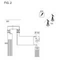
- FIGS. 1 and 2are schematic diagrams of combined thermal and compressed-gas energy conversion systems in accordance with various embodiments of the invention
- FIG. 3is a schematic diagram of an open-air hydraulic-pneumatic energy storage and recovery system in accordance with various embodiments of the invention
- FIG. 3Ais an enlarged schematic diagram of a portion of the system of FIG. 3 ;
- FIG. 4is a graphical representation of the thermal efficiencies obtained at different operating parameters
- FIG. 5is a schematic partial cross section of a hydraulic/pneumatic cylinder assembly including a heat-exchange subsystem that facilitates isothermal expansion within the pneumatic side of the cylinder, as well as a heat exchange subsystem facilitating heating and/or cooling the surroundings in accordance with various embodiments of the invention;
- FIGS. 6 and 7are schematic diagrams of liquid-spray-type mechanisms for expedited heat transfer to and from a gas undergoing compression or expansion in accordance with various embodiments of the invention
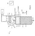
- FIGS. 8 and 9are schematic diagrams of compressed-gas storage subsystems for heating and cooling compressed gas in energy conversion systems in accordance with various embodiments of the invention.
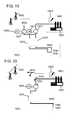
- FIG. 10 and FIG. 11are schematic diagrams of compressed-gas energy storage with a thermal well using a liquid-spray mechanism ( FIG. 10 ) or an air-circulation mechanism ( FIG. 11 ) for expedited heat transfer to and from a gas undergoing compression or expansion in accordance with various embodiments of the invention;
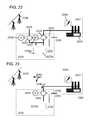
- FIG. 12is a schematic diagram of a system using pressurized stored gas to operate a double-acting pneumatic cylinder (shown in partial cross-section) to produce mechanical force that may be used to drive to an electric motor/generator (not shown) in accordance with various embodiments of the invention;
- FIG. 13shows the system of FIG. 12 in a different phase of operation in accordance with various embodiments of the invention
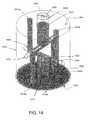
- FIG. 14shows a schematic perspective view of a piston drilled for drainage and injection of a heat transfer fluid for use in a cylinder for a system in accordance with various embodiments of the invention
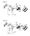
- FIGS. 15-18are schematic diagrams of systems for carbon dioxide sequestration using compressed-gas energy storage and biomass growth in accordance with various embodiments of the invention.
- FIGS. 19-25are schematic diagrams of systems for carbon dioxide extraction using compressed-gas energy storage in accordance with various embodiments of the invention.
- FIG. 26is a schematic diagram of a system for wind-energy generation and storage in accordance with various embodiments of the invention.
- the temperature of the compressed air stored in the systemcan be related to its pressure and volume through the ideal gas law and thus to the power output of the system during expansion. Therefore, pre-heating (before or during expansion) or pre-cooling (during compression) of the compressed gas and/or heat-exchange medium (e.g., water) in the heat-transfer circuit described in the '235 application may be used to increase power output (or decrease power input) of the compressed-air energy conversion system, improving overall effective efficiency (potentially exceeding 100% efficiency for electric input to electric output).
- Potential sources of pre-heating of the stored or expanding compressed gas and/or heat exchange mediuminclude waste heat from installations such as power plants and industrial processes and heat obtained from heat pumps, ground loops, solar thermal devices, and geothermal healing.
- Potential sources of pre-cooling for the heat-exchange mediuminclude heat pumps, ground loops, and cold water from the local environment.
- the heat exchange mediume.g., water
- the heat transfer circuit described in the '235 applicationbecomes cooler (provides thermal energy to the compressed air) during expansion and hotter (removes thermal energy from the compressed air) during compression.
- This movement of thermal energymay be used in combined heating or cooling applications such as space conditioning.
- compressed-gas energy conversion systemswill be located at power generation sites (e.g., coal, nuclear, solar thermal) that use heat engines producing substantial excess thermal energy.
- the systemmay be located at industrial sites with substantial waste process heat or otherwise freely available excess thermal energy.
- the power density of the systemmay be increased by preheating the stored compressed gas and/or coupling excess thermal energy with the gas during expansion.
- cooled water from this systemmay be used for cooling systems and/or building conditioning.
- local cooling sourcessuch as ground loops or cold water from the local environment may be used to promote cooling during compression by cooling the stored compressed gas or the gas being compressed, thus increasing the efficiency of the process.
- excess thermal energyis generated by the compressed-air energy conversion system. If extracted by an appropriate thermal system, this excess thermal energy may be used for process heat or building conditioning. Cooling from environmental sources may be combined with harvesting of excess storage-system heat by using the later for preheating of inputs to the installation being served. In all of these instances, performance and/or value of the storage system may be markedly improved.
- FIG. 1is a diagram of an illustrative embodiment of the major components of the systems and methods for heating and cooling of compressed gas for energy conversion systems.
- the systemconsists of an installation 101 where thermal energy is available for recovery, extracted from the surroundings, or needed for usage, or may be removed for cooling.
- Example installations 101include fossil-fuel based power plants (e.g., coal, natural gas); other heat-engine-based power plants such as nuclear, solar thermal, and geothermal; industrial processes with waste heat; heat pumps, heat sources, and heat sinks; buildings needing space heating or cooling; and sources of environmentally chilled water.
- a power plant 102is shown whose excess thermal energy is recoverable through a standard heat-exchange unit 104 .
- Generated power 103 from the power plant 102is used to drive the compressed-gas energy conversion system 110 as determined by the operator (e.g., when market demand for power is low), storing energy in the form of compressed gas in pressure vessels 120 , caverns, or other means of high-pressure gas storage. Upon demand for increased power, this stored energy in the form of compressed gas in pressure vessels 120 undergoes staged hydraulic expansion in the compressed-gas energy conversion system 110 to generate power for usage (e.g., power grid delivery 130 ).
- the recovered thermal energy from the power plant 102is used in the heat-exchange subsystem of the compressed-gas energy conversion system 110 to preheat the heat exchange fluid during expansion, increasing the work done by a given volume of pressurized gas, thus improving system efficiency and/or performance.
- cooled water from heat exchange with cold environments or other low-temperature reservoirsmay be used in the heat-exchange subsystem of the compressed-gas energy conversion system 110 to improve efficiency and/or performance during compression.
- excess thermal energy generated during air compressionmay be used for process heat or building conditioning.
- the cooled exchange fluidmay be used to cool the surroundings, e.g., for building conditioning.
- the recovered thermal energy from the power plant 102is used in the heat-exchange subsystem of the compressed-gas pressure vessels 120 (or other pressurized storage) to preheat the stored compressed gas and to heat the heat-exchange fluid and gas during expansion, increasing the work done by a given volume of pressurized gas and so improving system efficiency and/or performance.
- water cooled by heat exchange with cold environments, ground loops, or water loops, or other low-temperature reservoirsmay be used in the heat-exchange subsystem to pre-cool and continually cool the compressed gas prior to and during further compression, improving system efficiency and/or performance. In all of these instances, performance and/or value of the system may be markedly improved.
- FIG. 2illustrates an application where a ground loop (in this case with heat pump) is combined with the compressed-gas energy conversion system to improve round-trip energy storage efficiency.
- a ground loopin this case with heat pump
- FIG. 2the major components of systems and methods for heating and cooling of compressed gas for energy conversion systems are shown operating in combination with a ground-source heat pump.
- generated energy 210is used to drive the compressed-gas energy conversion system 110 as determined by the operator (e.g., when market costs or power demand are low), storing energy in the form of compressed gas in pressure vessels 120 , caverns, or other means of high-pressure gas storage.
- this stored energy in the form of compressed gas in pressure vessels 120undergoes staged pneumatic expansion through the compressed-gas energy conversion system 110 to generate power for usage (e.g., power grid delivery 130 ).
- a heat pump 201(or simply a circulation system, for a ground-loop-only system) is mated with the heat-exchange subsystem of pressure vessels 120 and/or the compressed-gas energy conversion system 110 .
- electric powerPrior to and/or during gas compression, electric power is used to run the heat pump (or simple circulator), which rejects thermal energy into the ground loop 202 and so cools the heat-exchange fluid and gas undergoing compression, thus reducing power requirements for compression.
- the overall efficiency (electric input to electric output) of the compressed-gas storage systemmay be increased and potentially exceed 100%.
- the heat-exchange fluid from the compressed-gas energy conversion system 110 and pressure vessels 120may be circulated directly through a ground or water loop.
- FIG. 3depicts generally a staged hydraulic-pneumatic energy conversion system that stores and recovers electrical energy using thermally conditioned compressed fluids and is featured in various embodiments of the invention.
- staged hydraulic-pneumatic energy conversion systemsthat store and recover electrical energy using compressed fluids are described in the '057 application.
- inventive concepts described hereinmay be used with any of those staged hydraulic-Pneumatic energy conversion systems, which are generally portions of the compressed-gas energy conversion system 110 described above.
- the system 300generally includes compressed-gas energy conversion system 110 and pressure vessels 120 .
- system 300includes five high-pressure gas/air storage tanks 302 - 302 e .
- Tanks 302 a and 302 b and tanks 302 c and 302 dare joined in parallel via manual valves 304 a , 304 b and 304 c , 304 d , respectively.
- Tank 302 calso includes a manual shut-off valve 304 c .
- the tanks 302are joined to a main air line 308 via pneumatic two-way (i.e., shut-off) valves 306 a , 306 b , 306 c .
- the tank output linesinclude pressure sensors 312 a , 312 b , 312 c .
- the lines/tanks 302may also include temperature sensors. The various sensors may be monitored by a system controller 360 via appropriate connections, as described in the '057 application.
- the main air line 308is coupled to a pair of multi-stage (two stages in this example) accumulator circuits via automatically controlled pneumatic shut-off valves 307 a , 307 b . These valves 307 a , 307 b are coupled to respective accumulators 316 and 317 .
- the air chambers 340 , 341 of the accumulators 316 , 317are connected via automatically controlled pneumatic shut-offs 307 c , 307 d to the air chambers 344 , 345 of the intensifiers 318 , 319 .
- Pneumatic shut-off valves 307 e , 307 fare also coupled to the air line connecting the respective accumulator and intensifier air chambers to respective atmospheric air vents 310 a , 310 b . This arrangement allows for air from the various tanks 302 to be selectively directed to either accumulator air chamber 344 , 345 .
- the various air lines and air chambersmay include pressure and temperature sensors 322 , 324 that deliver sensor telemetry to the controller 360 .
- the system 300also includes two heat-exchange subsystems 350 in fluid communication with the air chambers 340 , 341 , 344 , 345 of the accumulators and intensifiers 316 - 319 and the high pressure storage tanks 302 : these heat-transfer subsystems provide the improved isothermal expansion and compression of the gas.
- a simplified schematic of one of the heat exchange subsystems 350is shown in greater detail in FIG. 3A .
- Each heat-transfer subsystem 350includes a circulation apparatus 352 , at least one heat exchanger 354 , and pneumatic valves 356 .
- One circulation apparatus 352 , two heat exchangers 354 and two pneumatic valves 356are shown in FIGS.
- the circulation apparatus 352is a positive displacement pump capable of operating up to the high-pressure limit of the system (e.g., 3000 psi) or more and the two heat exchanger 354 are tube-in-shell type (also known as a shell-and-tube type).
- the heat exchangers 354also capable of operating up to high pressure (e.g., 3000 psi).
- the heat exchangers 354are shown connected in parallel but may also be connected in series.
- the heat exchangers 354may have the same or different heat-exchange areas.
- a control valve arrangementmay be used to selectively direct the gas flow to one or both of the heat exchangers 354 to obtain different heat-transfer areas (e.g., X, 2X, or 3X) and thus different thermal efficiencies.
- the system 350includes the circulation apparatus 352 , which may be driven by, for example, an electric motor 353 mechanically coupled thereto.
- the circulation apparatus 352may be a combination of accumulators, check valves, and an actuator.
- the circulation apparatus 352is in fluid communication with each of the air chambers 340 , 344 via a three-way, two-position pneumatic valve 356 B and draws gas from either air chamber 340 , 344 depending on the position of the valve 356 B.
- the circulation apparatus 352circulates the gas from the air chamber 340 , 344 to the heat exchanger 354 .
- the two heat exchangers 354are connected in parallel with a series of pneumatic shut-off valves 307 G- 307 J, that may regulate the flow of gas to heat exchanger 354 A, heat exchanger 354 B, or both.
- a bypass pneumatic shut-off valve 307 Kthat may be used to bypass the heat exchangers 354 (i.e., the heat-transfer subsystem 350 may be operated without circulating gas through either heat exchanger).
- the gasflows through a first side of the heat exchanger 354 while a constant temperature fluid source flows through a second side of the heat exchanger 354 .
- the fluid sourceis controlled to maintain the gas at ambient temperature.
- the gasmay be directed through the heat exchanger 354 , while the fluid source (at ambient or colder temperature) counter-flows through the heat exchanger 354 to remove heat from the gas.
- the gas outlet of the heat exchanger 354is in fluid communication with each of the air chambers 340 , 344 via a three-way, two-position pneumatic valve 356 A that returns the thermally conditioned gas to either air chamber 340 , 344 , depending on the position of the valve 356 A.
- the pneumatic valves 356are used to control from which hydraulic cylinder the gas is being thermally conditioned.
- the output of the fluid counter-flowcan be used to, for example, provide building conditioning.
- the various componentswill depend on the particular application with respect to, for example, fluid flows, heat transfer requirements, and location.
- the pneumatic valvesmay be electrically, hydraulically, pneumatically, or manually operated.
- the heat exchange subsystem 350may include at least one temperature sensor 322 that, in conjunction with the controller 360 ( FIG. 3 ), controls the operation of the various valves 307 , 356 and, thus the operation of the heat-transfer subsystem 350 .
- the heat exchange subsystemis used with a staged hydraulic-pneumatic energy conversion system as shown and described in the '057 application, where the two heat exchangers are connected in series.
- the operation of the heat-transfer subsystemis described with respect to the operation of a 1.5 gallon capacity piston accumulator having a 4-inch bore.
- the systemis capable of producing 1-1.5 kW of power during a 10 second expansion of the gas from 2900 psi to 350 psi.
- Two tube-in-shell heat exchange unitsone with a heat exchange area of 0.11 m 2 and the other with a heat exchange area of 0.22 m 2 , are in fluid communication with the air chamber of the accumulator.
- shut-off valvesmay be used to control the heat exchange counter flow, thus providing for no heat exchange, heat exchange with a single heat exchanger (i.e., with a heat exchange area of 0.11 m 2 or 0.22 m 2 ), or heat exchange with both heat exchangers (i.e., with a heat exchange area of 0.33 m 2 .)
- high-pressure airis drawn from the accumulator 316 and/or 317 and circulated through the heat exchangers 354 by the circulation apparatus 352 .
- the gas circulation/heat exchanger sub-circuit and remaining volume on the air side of the accumulatoris tilled with high-pressure (e.g., 3000 psi) air.
- the shut-off valves 307 G- 307 Jare used to select which, if any, heat exchanger to use.
- thermodynamic efficiency of the gas expansionmay be determined when the total fluid power energy output is compared to the theoretical energy output that could have been obtained by perfectly isothermal expansion of the known volume of gas.
- the overall work output and thermal efficiencymay be controlled by adjusting the hydraulic fluid flow rate and the heat exchanger area.
- FIG. 4depicts the relationship between power output, thermal efficiency, and heat-exchanger surface area for this exemplary embodiment of the systems 300 , 350 .
- By increasing heat-exchange areae.g., by adding heat exchangers to the heat exchange subsystem 350 , greater thermal efficiency is achieved over the power output range.
- thermal efficiencies above 90%may be achieved when using both heat exchangers 354 for average power outputs of approximately 1.0 kW.
- Increasing the gas circulation rate through the heat exchangerswill also provide additional efficiencies.
- the selection and sizing of the componentsmay be accomplished to optimize system design by balancing cost and size with power output and efficiency.
- the air chamber 340 , 341 of each accumulator 316 , 317is enclosed by a movable piston 336 , 337 having an appropriate sealing system using scaling rings and other components that are known to those of ordinary skill in the art.
- the piston 336 , 337moves along the accumulator housing in response to pressure differentials between the air chamber 340 , 341 and an opposing fluid chamber 338 , 339 , respectively, on the opposite side of the accumulator housing.
- the air chambers 344 , 345 of the respective intensifiers 318 , 319are also enclosed by a moving piston assembly 342 , 343 .
- the piston assembly 342 , 343includes an air piston 342 a , 343 a connected by a shaft, rod, or other coupling to a respective fluid piston 342 b , 343 b that moves in conjunction.
- the differences between the piston diametersallows a lower air pressure acting upon the air piston to generate a pressure on the associated fluid chamber similar to the higher air pressure acting on the accumulator piston.
- the systemallows for at least two stages of pressure to be employed to generate similar levels of fluid pressure.
- the accumulator fluid chambers 338 , 339are interconnected to a hydraulic motor/pump arrangement 330 via a hydraulic valve 328 a .
- the hydraulic motor/pump arrangement 330includes a first port 331 and a second port 333 .
- the arrangement 330also includes several optional valves, including a normally open shut-off valve 325 , a pressure relief valve 327 , and three check valves 329 that may further control the operation of the motor/pump arrangement 330 .
- check valves 329 a , 329 bdirect fluid flow from the motor/pump's leak port to the port 331 , 333 at a lower pressure.
- valves 325 , 329 cprevent the motor/pump from coming to a hard stop during an expansion cycle.
- the hydraulic valve 328 ais shown as a three-position, four-way directional valve that is electrically actuated and spring returned to a center closed position, where no flow through the valve 328 a is possible in the unactuated state.
- the directional valve 328 acontrols the fluid flow from the accumulator fluid chambers 338 , 339 to either the first port 331 or the second port 333 of the motor/pump arrangement 330 . This arrangement allows fluid from either accumulator fluid chamber 338 , 339 to drive the motor/pump 330 clockwise or counter-clockwise via a single valve.
- the intensifier fluid chambers 346 , 347are also interconnected to the hydraulic motor/pump arrangement 330 via a hydraulic valve 328 b .
- the hydraulic valve 328 bis also a three-position, four-way directional valve that is electrically actuated and spring returned to a center closed position, where no flow through the valve 328 b is possible in the unactuated state.
- the directional valve 328 bcontrols the fluid flow from the intensifier fluid chambers 346 , 347 to either the first port 331 or the second port 333 of the motor/pump arrangement 330 . This arrangement allows fluid from either intensifier fluid chamber 346 , 347 to drive the motor/pump 330 clockwise or counter-clockwise via a single valve.
- the motor/pump 330may be coupled to an electrical generator/motor and that drives and is driven by the motor/pump 330 .
- the generator/motor assemblymay be interconnected with a power distribution system and may be monitored for status and output/input level by the controller 360 .
- fluid lines and fluid chambersmay include pressure, temperature, or flow sensors and/or indicators 322 , 324 that deliver sensor telemetry to the controller 360 and/or provide visual indication of an operational state.
- the pistons 336 , 337 , 342 , 343may include position sensors 348 that report their present position to the controller 360 . The position of the piston may be used to determine relative pressure and flow of both gas and fluid.
- FIG. 5is an illustrative embodiment of an isothermal-expansion hydraulic/pneumatic system 550 in accordance with one embodiment of the invention.
- the systemincludes of a cylinder 501 containing a gas chamber or “pneumatic side” 502 and a fluid chamber or “hydraulic side” 504 separated by a movable (double arrow 540 ) piston 503 or other force/pressure-transmitting barrier that isolates the gas from the fluid.
- the cylinder 501may be a conventional, commercially available component, modified to receive additional ports as described below.
- Embodiments of the inventionmay include one or more intensifiers in addition to or instead of the cylinder 501 , as described in the '235 application.
- the cylinder 501includes a primary gas port 505 , which may be closed via valve 506 and that connects with a pneumatic circuit, or any other pneumatic source/storage system.
- the cylinder 501further includes a primary fluid port 507 that may be closed by valve 508 . This fluid port connects with a source of fluid in the hydraulic circuit of the above-described storage system, or any other fluid reservoir.
- the cylinder 501has one or more gas circulation outlet ports 510 that are connected via piping 511 to the gas circulator 552 .
- the terms “pipe,” “piping” and the likeshall refer to one or more conduits that are rated to carry gas or liquid between two points. Thus, the singular term should be taken to include a plurality of parallel conduits where appropriate.
- the gas circulator 552may be a conventional or customized low-head pneumatic pump, fan, or any other device for circulating a gas.
- the gas circulator 552should be sealed and rated for operation at the pressures contemplated within the gas chamber 502 . Thus, the gas circulator 552 creates a predetermined flow (arrow 530 ) of gas up the piping 511 and therethrough.
- the gas circulator 552may be powered by electricity from a power source or by another drive mechanism, such as a fluid motor.
- the mass-flow speed and on/off functions of the circulator 552may be controlled by a controller 560 acting on the power source for the circulator 552 .
- the controller 560may be a software and/or hardware-based system that carries out the heat-exchange procedures described herein.
- the outlet of the gas circulator 552is connected via a pipe 514 to the gas inlet 515 of a heat exchanger 554 .
- the heat exchanger 554 of the illustrative embodimentmay be any acceptable design that allows energy to be efficiently transferred between a high-pressure gas flow contained within a pressure conduit and another mass flow (fluid).
- the rate of heat exchangeis based in part on the relative flow rates of the gas and fluid, the exchange-surface area between the gas and fluid, and the thermal conductivity of the interface therebetween.
- the gas flowis heated or cooled, depending on the stage of operation of the energy conversion system, in the heat exchanger 554 by the fluid counter-flow passing through piping 517 (arrows 526 ), which enters the fluid inlet 518 of heat exchanger 554 at ambient temperature and exits the heat exchanger 554 at the fluid exit 519 equal or approximately equal in temperature to the gas in piping 514 .
- the gas flow at gas exit 520 of heat exchanger 554is at ambient or approximately ambient temperature, and returns via piping 521 through one or more gas circulation inlet ports 522 to gas chamber 502 .
- “ambient”is meant the temperature of the surrounding environment or any other temperature at which efficient performance of the system can be achieved.
- the ambient-temperature gas reentering the cylinder's gas chamber 502 at the circulation inlet ports 522mixes with the gas in the gas chamber 502 , thereby bringing the temperature of the fluid in the gas chamber 502 closer to ambient temperature.
- the controller 560manages the rate of heat exchange based, for example, on the prevailing temperature (T) of the gas within the gas chamber 502 as determined using a temperature sensor 513 B of conventional design that thermally communicates with the gas within the chamber 502 .
- the sensor 513 Bmay be placed at any location along the cylinder including a location that is at, or adjacent to, the heat exchanger gas inlet port 510 .
- the controller 560reads the value T from the cylinder sensor and compares it to an ambient temperature value (TA) derived from a sensor 513 C located somewhere within the system environment.
- TAambient temperature value
- the heat exchange subsystem 550is directed to move gas (by powering the circulator 552 ) therethrough at a rate that may be partly dependent upon the temperature differential (so that the exchange does not overshoot or undershoot the desired rate of heat exchange.
- Additional sensorsmay be located at various locations within the heat-exchange subsystem to provide additional telemetry that may be used by a more complex control algorithm. For example, the outlet gas temperature (TO) from the heat exchanger may measured by a sensor 513 A that is placed upstream of the inlet port 522 .
- the heat exchanger's fluid circuitmay be filled with water, a coolant mixture, and/or any acceptable heat-transfer medium.
- a gassuch as air or refrigerant
- the fluidis routed by conduits to a large reservoir of such fluid in a closed or open loop.
- an open loopis a well or body of water from which ambient water is drawn and the exhaust water is delivered to a different location, for example, downstream in a river.
- a cooling towermay cycle the water through the air for return to the heat exchanger.
- watermay pass through a submerged or buried coil of continuous piping where a counter heat-exchange occurs to return the fluid flow to ambient temperature before it returns to the heat exchanger for another cycle.
- the isothermal operation of embodiments of this inventionworks in two directions thermodynamically.
- the gasmay be warmed toward ambient by the heat exchanger during expansion or cooled toward ambient by the heat exchanger during compression; in the latter case, without cooling, significant internal heat may build up via compression.
- the heat-exchanger componentsshould therefore be rated to handle at least the temperature range likely to be encountered for entering gas and exiting fluid.
- the heat exchangersince the heat exchanger is external to the hydraulic/pneumatic cylinder, it may be located anywhere that is convenient and may be sized as needed to deliver a high rate of heat exchange.
- itmay be attached to the cylinder with straightforward taps or ports that are readily installed on the base end of an existing, commercially available hydraulic/pneumatic cylinder.
- the heat-exchange fluidmay be conditioned (i.e., pre-heated and/or pre-chilled) or used for heating or cooling needs by connecting the fluid inlet 518 and fluid outlet 519 of the external heat exchange side of the heat exchanger 554 to an installation 570 , such as heat-engine power plants, industrial processes with waste heat, heat pumps, and buildings needing space heating or cooling.
- an installation 570such as heat-engine power plants, industrial processes with waste heat, heat pumps, and buildings needing space heating or cooling.
- installation 570is merely a large water reservoir that acts as a constant temperature thermal fluid source for use with the system.
- the water reservoirmay be thermally linked to waste heat from an industrial process or the like, as described above, via another heat exchanger contained within the installation 570 . This allows the heat exchange fluid to acquire or expel heat from/to the linked process, depending on configuration, for later use as a heating/cooling medium in the compressed air energy storage/conversion system.
- FIGS. 6 and 7depict simplified alternative embodiments of isothermal-expansion hydraulic/pneumatic system 550 using spray-type heat-transfer schemes, such as those described in the '703 application.
- heat transferis improved through the use of a liquid circulator, heat exchanger circuit, and a spray head, where the liquid is sprayed downward into a vertical cylinder.
- a vertically oriented hydraulic-pneumatic cylinder (accumulator, intensifier, or other hydraulic-pneumatic assembly) 601 having a hydraulic side 602 separated from a gas side 603 by a moveable piston 604is shown in a state of operation where compressed gas from a pressure vessel, not shown but indicated by 605 , is admitted to the gas side 603 .
- gasmay be exhausted from the gas side 603 through a vent, not shown but indicated by 606 .
- the gas expanding in the gas side 603tends to cool according to the ideal gas law. Greater effective efficiency may be achieved if heat is transferred to the gas during expansion. This may be achieved by the introduction into the gas side 603 of a heated liquid (e.g., water) spray 608 through a spray head or heads 609 .
- a heated liquide.g., water
- This liquidfalls as a spray or droplets through the gas side 603 , exchanging heat with the expanding gas; accumulates 610 in the bottom of the gas side; is conducted out of the gas side (it is herein illustrated as exiting through a center-drilled piston rod) and passes through piping 611 to heat exchanger 654 , where it is heated; exits the heat exchanger to pass through a circulator 613 ; and is again sprayed through the spray head 609 .
- Heatis delivered to heat exchanger 554 by a circuit 614 that communicates with some source of heat (e.g., an installation 570 as described above). Operated appropriately, this mechanism will achieve substantially isothermal expansion of the compressed gas from the reservoir 605 , with resulting power output and total recoverable energy superior to that achievable otherwise.
- FIG. 7is a schematic representation of a system and method for expedited heat transfer to a gas in a staged hydraulic-pneumatic system where the heat transfer is improved through the use of a liquid circulator, heat exchanger circuit, and spray rod, where the liquid is sprayed radially into an arbitrarily-oriented cylinder.
- the heat-exchange liquidis sprayed outward 608 from a central spray rod 701 into the arbitrarily oriented cylinder.
- the cylinderis oriented vertically; however, it may be oriented horizontally or obliquely.
- a vertically oriented hydraulic-pneumatic cylinder (accumulator, intensifier, or other hydraulic-pneumatic assembly) 601 having a hydraulic side 602 separated from a gas side 603 by a moveable piston 604is shown in a state of operation where compressed gas from a pressure vessel, not shown but indicated by 605 , is admitted to the gas side 603 of the intensifier 601 .
- gasmay be exhausted from the gas side 603 through a vent, not shown but indicated by 606 .
- the gas expanding in the gas side 603 of the cylinder 601tends to cool. Greater effective efficiency may be achieved if heat is transferred to the gas during expansion. This may be achieved by the introduction into the gas side 603 of a heated liquid spray 608 from a hollow spray rod 701 .
- the spray rod 701is perforated at intervals along its whole length and around its circumference so that the whole open volume of the gas side 603 is sprayed with droplets.
- the spray rodis concentric with the shall 702 attached to the piston 604 , so that spray is emitted only by whatever portion of the spray rod 701 is exposed in the gas side 603 of the cylinder 601 .
- This arrangementis for illustrative purposes and any other system or method for allowing an appropriate length of the spray rod (or multiple spray rods) to spray the interior of the gas side 603 of the intensifier would embody the same invention.
- the spray dropletspass through the gas side 603 , exchanging heat with the expanding gas.
- Liquidaccumulates 610 in whatever portion of the gas side is bottommost; is conducted out of the gas side through a line 611 (herein illustrated as exiting through a center-drilled piston rod) to a heat exchanger 554 where it is heated; exits the heat exchanger to pass through a circulator 613 ; and is again introduced into the interior of the hollow spray rod 701 .
- Heatis delivered to the heat exchanger 554 by a circuit 614 that communicates with a source of heat, e.g. an installation 570 as described above.
- heat-transfer subsystems discussed abovemay also be used in conjunction with the high pressure gas storage systems (e.g., storage tanks 302 ) thermally condition the pressurized gas stored therein, as shown in FIGS. 8 and 9 .
- these systemsare arranged and operate in the same manner as described above.
- FIG. 8depicts the use of a heat-transfer subsystem 850 in conjunction with a gas storage system 801 for use with the compressed-gas energy conversion systems described herein, to expedite transfer of thermal energy to, for example, the compressed gas prior to and during expansion.
- Compressed air from the pressure vessels ( 802 a - 802 d )is circulated through a heat exchanger 854 using an air pump 852 operating as a circulator.
- the air pump 852operates with a small pressure change sufficient for circulation, but within a housing that is able to withstand high pressures.
- the air pump 852circulates the high-pressure air through the heat exchanger 854 without substantially increasing its pressure (e.g., a 50 psi increase for 3000 psi air).
- the stored compressed airmay be pre-heated (or pre cooled) by opening valve 804 with valve 806 closed and heated during expansion or cooled during compression by closing 804 and opening 806 .
- the heat exchanger 854may be any sort of standard heat-exchanger design; illustrated here is a tube-in-shell type heat exchanger with high-pressure air inlet and outlet ports 821 a and 821 b and low-pressure shell ports 822 a and 822 b (which may be connected to an external heating or cooling source, as described above).
- FIG. 9depicts the use of a heat exchange subsystem 950 in conjunction with a gas storage system 901 for use with the compressed gas in energy conversion systems described herein, to expedite transfer of thermal energy to the compressed gas prior to and during expansion.
- thermal energy transfer to and from the stored compressed gas in pressure vessels ( 902 a and 902 b )is expedited by a water circulation scheme using a water pump 952 and heat exchanger 954 .
- the water pump 952operates with a small pressure change sufficient for circulation and spray but within a housing that is able to withstand high pressures.
- the water pump 952circulates high-pressure water through heat exchanger 954 and sprays the water into pressure vessels 902 without substantially increasing its pressure (e.g., a 100 psi increase for circulating and spraying within 3000 psi stored compressed air).
- the stored compressed airmay be pre-heated (or pre-cooled) using a water circulation and spraying method.
- the spray heat exchangemay occur either as pre-heating prior to expansion or, when valve 906 is opened, pre-cooling prior to compression in the system.
- the heat exchanger 954may be any sort of standard heat exchanger design; illustrated here is a tube-in-shell type heat exchanger with high-pressure water inlet and outlet ports 921 a and 921 b and low-pressure shell ports 922 a and 922 b (which may be, connected to an external heating or cooling source, as described above).
- heat exchanger sizemay be reduced and/or heat transfer may be improved by use of a liquid-to-liquid heat exchanger.
- Heat exchange within the pressure vessels 902is expedited by active spraying of the liquid (e.g., water) into the pressure vessels 902 .
- a perforated spray rod 911 a , 911 bis installed within each pressure vessel 902 a , 902 b .
- the water pump 952increases the water pressure above the vessel pressure such that water is actively circulated and sprayed out of rods 911 a and 911 b , as shown by arrows 912 a and 912 b .
- a tier spraying through the volume of the pressure vessels 902the water settles to the bottom of the vessels 902 (sec 913 a , 913 b ) and is then removed through a drainage port 914 a , 914 b .
- the watermay be circulated through the heat exchanger 954 as part of the closed-loop water circulation and spray system.
- FIG. 10depicts an embodiment of a compressed-gas energy conversion system with combined thermal well, where a liquid is sprayed downward into a vertically oriented cylinder to expedite heat transfer to the gas in the compressed-gas energy conversion system.
- the system 1000includes some of the same components of the energy-storage system labeled 110 in FIG. 1 .
- a vertically oriented hydraulic-pneumatic cylinder (accumulator, intensifier, or other hydraulic-pneumatic assembly) 1001 having a fluid chamber or “hydraulic side” 1002 separated from a gas chamber or “pneumatic side” 1003 by a moveable piston 1004is shown in a state of operation where compressed gas from a pressure vessel (e.g., 120 in FIG. 1 ), not shown but indicated by 1005 , is admitted to the pneumatic side 1003 . In other states of operation, gas may be exhausted from the pneumatic side 1003 through a vent, not shown, but indicated by 1006 .
- a pressure vessele.g., 120 in FIG. 1
- Liquidmay be admitted to the hydraulic side 1002 from any source (e.g., the liquid outlet of the hydraulic motor/pump), not shown, but indicated by 1008 .
- the gas expanding in the pneumatic side 1003tends to cool according to the ideal gas law. Greater effective efficiency is achieved if heat is transferred to the gas during expansion.
- Thisis achieved by the introduction of a heated liquid into the pneumatic side 1003 of the cylinder.
- the heated liquide.g., water
- the heated liquidmay be introduced as a spray 1008 through a spray head or heads 1009 .
- This liquidfalls as a spray or droplets through the pneumatic side 1003 , exchanging heat with the expanding gas.
- the liquidaccumulates 1010 in the bottom of the pneumatic side 1003 and is drawn out of the pneumatic side 1003 of the cylinder. As shown in FIG.
- the liquidis drawn out of the cylinder 1001 via a center-drilled piston rod; however, other means for removing the liquid are contemplated and within the scope of the invention.
- the liquidis drawn through piping 1011 to a heat exchanger 1012 ; exits the heat exchanger 1012 via a circulator 1013 ; and is again introduced into the gas side 1003 through the spray head 1009 .
- Other mechanisms for introducing the liquid to the pneumatic sideare contemplated and within the scope of the invention.
- the heat exchanger 1012passes through a thermal well 1014 , shown here as a water reservoir.
- a thermal well 1014shown here as a water reservoir.
- this systemwill achieve substantially isothermal expansion of the compressed gas from the reservoir 1005 , with resulting power output and total recoverable energy superior to that achievable otherwise.
- the thermal energy delivered by the heat-exchange circuit and liquid spray to the expanding gasmay raise its temperature, thereby increasing mechanical work that is delivered by the cylinder to the motor/generator and the amount of electricity produced.
- thermal energymay be transferred from the compressing gas to the liquid spray and then to the thermal well.
- thermal energymay be transferred from the compressing gas to the liquid spray and then to the thermal well.
- equal amounts of thermal energywill be stored and returned from the thermal well. Due to inefficiencies in the energy conversion system, the thermal well will actually gain in thermal energy over the course of a full compression and expansion process. This gain in thermal energy may be dissipated by means such as an environmental heat exchanger or other heat transfer, such as losses through imperfect insulation.
- the gain in thermal energymay be utilized as a heat source for process heat or building conditioning, as described above.
- FIG. 11depicts another embodiment of a compressed-gas energy conversion system with combined thermal well 1100 , where the gas is circulated through a heat exchanger 1123 external to the expanding cylinder volume.
- a portion of the compressed-gas energy conversion system, including the heat exchange subsystem,is shown to illustrate the heat exchange process.
- the system 1100includes some of the same components of the energy-storage system labeled 110 in FIG. 1 .
- FIG. 1depicts another embodiment of a compressed-gas energy conversion system with combined thermal well 1100 , where the gas is circulated through a heat exchanger 1123 external to the expanding
- a single stage of the staged compressed-gas energy conversion systemis represented by a cylinder 1110 , which contains a gas chamber or “pneumatic side” 1112 and a fluid chamber or “hydraulic side” 1111 separated by a movable (double arrow 1116 ) piston 1113 or other force/pressure-transmitting barrier that isolates the gas from the fluid.
- the cylinder 1110includes a primary gas port 1115 that connects with a pneumatic circuit that for compression admits the uncompressed gases and eventually outputs the compressed gas and for expansion admits the compressed gases and outputs the decompressed gases.
- the cylinder 1110further includes a primary fluid port 1114 that connects with a hydraulic drive circuit of the storage system that for compression admits the pressurized fluid to drive the piston 1116 and compress the gases in pneumatic side 1112 and for expansion outputs the pressurized fluid to drive a motor generator.
- the cylinder 1110has one or more gas circulation outlet ports 1117 , which are connected via piping 1122 to a gas circulator 1120 , which may be part of the heat exchange subsystem described in the '235 application.
- the gas circulator 1120provides a flow (arrow 1121 ) of gas through the piping 1122 .
- the outlet of the gas circulator 1120is connected via a pipe to the gas inlet of the heat exchanger 1123 .
- the heat exchanger 1123may pass directly through the thermal well, or as shown here, other connections on the heat exchanger 1123 may bring an external heat exchange fluid (e.g., water) from the thermal well 1130 to the heat exchanger 1123 to provide or extract thermal energy from the circulating compressed gas, thereby maintaining the gas at nearly the temperature of the exchange fluid.
- a fluid circulator 1124is used to circulate the heat exchange fluid through the heat exchanger 1123 .
- the system 1100improves efficiency and power output of the compressed-gas energy conversion system.
- FIG. 12is a schematic diagram of a system and method for using pressurized stored gas to operate a double-acting pneumatic cylinder to produce mechanical motion that may be used to drive to an electric motor/generator (not shown, but similar to those described in the '057 application) in accordance with an embodiment of the invention.
- sprays of heat-exchange liquidmay be introduced into either compartment of the cylinder to enable approximately isothermal expansion (or compression) of gas.
- a hydraulic pumpin this exemplary embodiment, a double-acting two-chamber hydraulic cylinder pressurizes the heat-exchange liquid for injection into the cylinder. Heat-exchange liquid is recycled from the high-pressure chamber to allow the hydraulic pump to operate more efficiently than if the liquid had to be pressurized starting from a lower pressure (e.g., atmospheric).
- the systemincludes a pneumatic cylinder 1200 divided into two compartments 1201 , 1202 by a piston 1203 .
- the cylinder 1200which is shown in a vertical orientation in this illustrative embodiment, has one or more gas ports 1204 that may exchange gas with other devices through piping 1205 .
- pressurized gas from a reservoir 1206passes through a valve 1208 and drives the piston 1203 of the double-acting high-pressure cylinder 1200 in the upward direction.
- Gas from the lower-pressure side (in this case compartment 1202 ) of the cylinder 1200is directed through a valve 1209 to a vent 1210 .
- liquid spraysmay be introduced into either of the compartments 1201 , 1202 or the cylinder 1200 .
- the liquid, sprayed downward,allows for expedited heat transfer with the high-pressure gas being expanded (or compressed) in the cylinder 1200 , as described in detail above.
- gasis expanded in chamber 1201 beginning at high pressure, e.g., 3000 psi.
- Spray droplets 1211are introduced into the chamber 1201 at a higher pressure (e.g., 3010 psi) than that of the gas in the chamber via perforated spray heads 1212 .
- the function of this sprayis to warm the high-pressure gas as it expands. (If gas is being compressed, the sprays serve to cool the gas.)
- Liquid 1213 accumulating at the bottom of the chamber 1201is removed at a pressure substantially the same as that of the gas inside the expansion chamber (e.g., 3000 psi at the start of the expansion) through a port 1207 and conveyed via piping 1214 to a heat exchanger 1215 to raise its temperature, which has been reduced by heat exchange with the expanding gas.
- the heat exchanger 1215is shown for illustrative purposes and may be located anywhere in the circuit; moreover, its function may be performed during system idle times through circulation of water at low pressure or with replacement from a larger water bath.
- the liquidpasses through a four-way, two-position valve 1216 that directs it to whichever of the two chambers of a double-acting hydraulic cylinder 1217 is presently being filled. In the state of operation shown in FIG. 12 , this happens to be chamber 1218 .
- the valve 1216allows the hydraulic cylinder 1217 to pump liquid through the recycling loop in the same sense regardless of which way the hydraulic cylinder's piston 1231 is moving.
- a four-way, two-position valve 1216is shown for illustrative purposes and may be replaced by check valves or other valve arrangements.
- the shalt 1219 of the hydraulic cylinderis driven by an actuator or motor 1220 .
- the entire pumping unit 1217is shown for illustrative purposes as a driven double-acting cylinder; however, the pumping unit may be any means for pumping a fluid, such as a modified gear-based hydraulic pump able to withstand high inlet pressures.
- Liquid pressurized by the hydraulic cylinder 1217(i.e., in chamber 1221 , in this state of operation) is directed through the valve 1216 , through piping 1222 , through a flexible hose 1223 , and into a center-drilled channel 1224 in one side of a piston shaft 1233 of the pneumatic cylinder 1200 .
- Channels 1225 formed within the body of the piston 1203direct the heat-exchange liquid to the spray heads 1212 .
- the arrangement of channels and spray heads shown hereis illustrative only, as any number and disposition of channels and spray heads or other spray devices inside the cylinder 1200 and its piston 1203 may be selected to suit a particular application: such variations are expressly contemplated and within the scope of the invention.
- the conceptis also independent of whatever pumping mechanism is used to pressurize the heat-exchange liquid in the hydraulic loop.
- FIG. 13shows the illustrative embodiment of FIG. 12 in a second operating state (i.e., with the high- and low-pressure sides of the piston reversed, the direction of shaft motion reversed, and the other hydraulic loop in use).
- the piston shaft 1233 of the pneumatic cylinder 1200has a direction of motion opposite to that shown in FIG. 12 .
- Gasflows from the high-pressure reservoir 1206 through valve 1301 into compartment 1202 of the cylinder 1200 .
- Gas at low pressureflows from chamber 1201 of the pneumatic cylinder 1200 through a valve 1302 to the vent 1210 .
- gasis expanded in chamber 1201 beginning at about, for example, 3000 psi.
- Spray droplets 1302are introduced into the chamber at a pressure (e.g., 3010 psi) higher than that of the gas in the chamber via perforated spray heads 1303 .
- Liquid 1304 accumulating at the bottom of the chamber 1202is removed through channels 1305 formed in the body of the piston 1203 and then through a center-drilled channel 1306 in one side of the piston shaft 1233 .
- the piston 1203moves downward, as indicated by the arrow 1307 .
- the heat-exchange liquidis passed through a flexible hose 1323 , a heat exchanger 1315 , a four-way, two-position valve 1316 , and raised to injection pressure by a hydraulic cylinder 1317 driven by an actuator 1320 . It is then passed through the valve 1316 again and returned to the spray heads 1303 for injection into chamber 1202 , in a process similar to that described with respect to FIG. 12 .
- the mechanism shown in FIGS. 12 and 13may employ electricity to produce pressurized stored gas; in such a case, the sprays here shown as heating gas undergoing expansion may be used, instead, to cool gas undergoing compression.
- FIG. 14depicts a schematic perspective view for one design for a piston head drilled to allow fluid to flow from off-center holes in one piston side to a centered piston hole in the other side, with the centered piston hole potentially connected to a center drilled piston rod, as shown in FIGS. 12 and 13 .
- This piston headallows for the heat transfer fluid to be removed and injected as described in FIGS. 12 and 13 .
- a cylindrical piston head 1400is shown having a top face 1401 and a bottom face 1402 , which when inserted in a honed cylinder (not shown) is separated by a seal mechanism (not shown) around the exterior curved surface of the piston head 1400 .
- the piston head 1400is shown with a centrally located machined hole 1413 on the top face 1401 for holding a piston rod 1403 , shown here with a center drilled passage 1405 .
- the break lines 1405 aindicate that the piston rod may be of any length, presumably longer than the cylinder stroke length.
- the piston headis shown with a centrally located machined hole 1415 on the bottom face 1402 for holding a piston rod 1404 , shown here with center drilled passage 1406 .
- the holes 1413 , 1415are referred to as vertical in the orientation as shown in FIG. 14 .
- a horizontal hole 1408is drilled through the piston head, connecting with the hole 1413 and the channel created by center drilled passage 1405 .
- This hole 1408may be drilled through the entire piston head and plugged as indicated by dashed line 1410 .
- a second horizontal hole 1407is drilled through the piston head to connect with hole 1415 and the channel created by center drilled passage 1406 .
- Hole 1408is shown rotated with respect to hole 1407 by 90 degrees when viewed from the top side 1401 or the bottom side 1402 .
- This hole 1407may be drilled through the entire piston head and plugged as indicated by dashed line 1409 .
- Vertical holes 1411 a , 1411 bare drilled from the top face 1401 to intersect with hole 1407 , but not through the piston, thus maintaining the integrity of the seal mechanism (not shown) separating the top and bottom compartments of a cylinder in which the piston is disposed.
- Additional vertical holes 1412 a , 1412 bare drilled from the bottom face 1402 to intersect with hole 1408 , but not through the piston, again maintaining the integrity of the seal mechanism (not shown) separating the top and bottom compartments of the cylinder.
- fluidmay flow from (or into) the top side 1401 of the piston through holes 1411 a , 1411 b , through hole 1407 , and out hole 1406 , allowing fluid to be continuously pulled from the top compartment of the cylinder regardless of piston position.
- fluidmay flow into (or from) center drilled passage 1405 , through hole 1408 , and out holes 1412 a , 1412 b out of the bottom side 1402 of the piston into the cylinder regardless of piston position.
- This illustrationindicates one method of machining a cylindrical piston head for injection and removal of heat transfer fluid.
- Other means of machining the piston head and other orientations for achieving the same function, such as angled holes, for example as shown schematically in FIGS. 12 and 13will be apparent to any person reasonably skilled in the art.
- the system shown in FIGS. 12 and 13may clearly also be operated in compression mode.
- an electric motor/generator(not shown) coupled in a manner to drive the pneumatic cylinder shalt is operated and the droplet-spray mechanism is used to cool gas undergoing compression for delivery to the storage reservoir, rather than to warm gas undergoing expansion from the reservoir.
- the mechanism shown in this illustrative embodimentmay thus operate as a full-cycle energy conversion system with high efficiency.
- the system shown in FIGS. 12 and 13may draw or deliver thermal energy via their heat-exchange mechanisms to external systems, as described above.
- the systems shown in FIGS. 12 and 13may also be modified to employ multiple pneumatic cylinders in series to reduce the operating pressure range of the system for further increase of efficiency, as described, for example, in U.S. Provisional Patent Application No. 61/257,583, the entire disclosure of which is incorporated by reference herein.
- such systemsmay include multiple, fluidly coupled pneumatic cylinders, and may operate in an expansion mode and then a compression mode.
- Embodiments of the invention disclosed hereinmay be utilized in a variety of applications, including extraction, sequestration, and subsequent use of gases emitted from power plants, such as carbon dioxide.
- Fossil fuel-based power generationas of 2008, accounts for a large fraction of the world's generated energy. While pollution control equipment can successfully capture much of the criteria emissions (e.g., sulfur dioxide, nitrogen oxides, particulates) at low-percentage energy consumption and cost, carbon dioxide (CO 2 ) sequestration systems for fossil fuel power plants remain prohibitively energy intensive (utilizing 20-40% of the total energy generated) and expensive.
- One potential method of carbon dioxide fixation from power plants emissionsis through the growth of plant-based biomass.
- biomass growth for CO 2 emission mitigationdescribed in US Patent Application Publication No. 2007/0289206, the disclosure of which is hereby incorporated by reference in its entirety, in which high-growth-rate algae is grown in a carbon-dioxide-rich environment.
- the grown biomasse.g., algae
- the grown biomasshas the potential to be used as an energy carrier through the extraction of oils (biodiesel) and/or processing for use as other biofuels (e.g. ethanol).
- oilsbiodiesel
- processing for use as other biofuelse.g. ethanol
- the sequestered carbon dioxidewill be released.
- the net effectis an approximate halving of the carbon dioxide emissions for both processes (power plant generation and biofuel usage (e.g., transportation).
- Embodiments of the inventionovercome the disadvantages of the prior art by combining biomass carbon dioxide sequestration with compressed-gas energy storage to allow for a cost-effective means of both storing energy and sequestering carbon dioxide at all times, day and night.
- the gas emissions from a power plantare compressed and stored, primarily during nighttime hours, in effect storing both energy and carbon-dioxide-rich power plant gas emissions.
- carbon-dioxide-rich power plant gas emissionsare directed to a biomass sequestration facility, such as algae ponds or bioreactors.
- compressed and stored carbon-dioxide-rich gas emissionsare expanded, generating usable/saleable power; after expansion, these previously stored carbon dioxide-rich gas emissions may also be directed to the biomass sequestration facility.
- FIG. 15is a diagram of an illustrative embodiment of the major systems for carbon dioxide sequestration using compressed-gas energy storage and biomass growth, in accordance with one embodiment of the invention.
- the illustrated systemincludes a fossil-fuel based power plant (e.g., one consuming coal and/or natural gas) 1501 , with simplified outputs of gas emissions 1502 and generated power 1503 .
- Additional componentsinclude a biomass-based carbon dioxide sequestration system 1510 , a compressed-gas energy conversion system 1520 , and, for illustrative purposes, the market usage of the generated power 1530 .
- the major components of the compressed-gas energy conversion system 1520may include any or all of the features described above with reference to compressed-gas energy conversion systems. As illustrated, these include a motor/generator 1521 , a gas compressor/expander 1522 , and a means of compressed gas storage 1523 (e.g., pressure vessels, caverns).
- FIGS. 16-18illustrate three states of carbon dioxide sequestration using compressed-gas energy storage and biomass growth.
- the major systemsare shown operating in a state where no power-plant energy is being stored or recovered from the compressed-gas energy conversion system. In this state, typically during daytime hours, power is fully transmitted for market usage of the generated power 1530 , as indicated by the connection and arrow 1650 .
- Power-plant gas emissions 1502are directed to the biomass-based carbon dioxide sequestration system 1510 , as indicated by the connection and arrow 1640 .
- FIG. 17the major systems for carbon dioxide sequestration using compressed-gas energy storage and biomass growth are shown in a state in which some power-plant energy and all carbon-dioxide-rich power plant gas emissions are being stored by the compressed-gas energy conversion system.
- this statetypically during nighttime hours, some portion of the generated power is transmitted for market usage 1530 and some generated power is utilized to drive the motor 1521 and compressor 1522 (as indicated by the connection and arrow 1750 ), compressing gas 1523 to store energy.
- Power-plant gas emissions 1502are compressed and stored into the means of compressed gas storage 1523 as part of this method as indicated by the connection and arrow 1740 . Additional air or other gases beyond the power plant gas emissions may be compressed and stored depending on market demand and costs.
- FIG. 18the major systems for carbon dioxide sequestration using compressed-gas energy storage and biomass growth are shown in a state in which market or other demand for stored energy exists.
- previously compressed and stored carbon dioxide-rich gas emissions in the means of compressed gas storage 1523are expanded through an expander 1522 and generator 1521 generating usable/saleable power which, along with the power from the current operation of the power plant, is transmitted for market usage 1530 , as indicated by the connections and arrows 1850 and 1851 .
- these previously stored carbon dioxide-rich gas emissions, along with current gas emissions from operation of the power plantare directed to the biomass facility 1510 , as indicated by the connections and arrows 1840 and 1841 .
- Systems and methods of carbon dioxide extraction from power plants emissions in accordance with embodiments of the inventionfeature compression of the emission gases to high pressure such that a portion of the carbon dioxide present undergoes a phase change to liquid and/or a supercritical fluid state.
- pure carbon dioxideundergoes a phase change from gas to liquid at approximately 30 atm (440 psi) at 20° C. and 71 atm (1050 psi) at 31° C.
- 31° C. and 71 atmis the critical point for carbon dioxide
- carbon dioxidewill be a combination of gas, liquid, and/or supercritical fluid, depending on the pressure.
- Carbon dioxide in a gas mixturei.e., impure carbon dioxide
- a gas mixturei.e., impure carbon dioxide
- a portion of carbon dioxide at a 10% concentration (by volume) in gas emissionswill liquefy at 20° C. when the overall pressure reaches 300 atm (4400 psi), thus bringing the partial pressure of carbon dioxide to 30 atm.
- very high pressures or reduced temperatureis generally needed.
- the carbon dioxideis liquefied or in the form of a supercritical fluid, it will typically sink to the bottom of the storage vessel due to its higher density. Removal of the liquefied or supercritical carbon dioxide may then be accomplished mechanically.
- Example mechanical apparatus for separation of the liquefied or supercritical carbon dioxide, among others,are described in U.S. Pat. Nos. 5,690,828 and 5,866,004, the disclosures of which are hereby incorporated herein by reference in their entireties.
- Systems and methods for carbon dioxide extraction from carbon dioxide-rich gas emissionsmay involve the chemical processing of carbon dioxide rich gas emissions, such as in U.S. Pat. No. 6,497,852, where the recovery is done by passing the emissions over a material such as a “liquid absorbent fluid comprising an organic amine absorbent,” or as in U.S. Pat. No. 6,235,092, where separation is accomplished by “contact . . . with carbon dioxide nucleated water under conditions or selective carbon dioxide clathrate formation.”
- the extracted carbon dioxidemay be compressed after extraction to form a liquid or supercritical fluid where it may be sequestered at depth or sold as a useful solvent for such things as dry cleaning and contaminant removal. Additionally, among other applications, the extracted carbon dioxide may be used for biofuel production.
- the compressed-gas energy conversion systems described hereinmay be used for further cooling of compressed gases and thus extraction of carbon dioxide at low pressures.
- Such systemscan concurrently process the carbon dioxide-rich power plant gas emissions (e.g., 2-30% carbon dioxide) for partial extraction of the carbon dioxide from said emissions.
- the combination of fossil fuel-based power plants, compressed-gas energy storage, and compression-based carbon dioxide extractionprovides an economically feasible solution to both energy storage needs and carbon dioxide extraction.
- the added benefit of carbon dioxide extraction through the compression processfurther increases the value of the compressed-gas energy conversion system, providing carbon dioxide in liquid or supercritical fluid form, both reducing carbon dioxide gas emissions and providing a potential resource for use as solvent or otherwise.
- Embodiments of the inventioncombine mechanical carbon dioxide extraction systems and methods with compressed-gas energy storage to allow for a cost-effective means of both storing energy and extracting carbon dioxide.
- Gas emissions from a power plantare compressed to high pressures using any of the compressed-air energy-storage systems described above, and then a portion of the carbon dioxide is extracted mechanically, in effect both storing energy and extracting carbon dioxide from carbon dioxide-rich power plant gas emissions.
- the processed and compressed power plant gas emissionsare expanded, recovering most of the stored energy, while the extracted carbon dioxide is sold, utilized, or sequestered.
- compressed-gas energy conversion systemsare utilized to concurrently store energy and capture carbon dioxide at a coal-tired or other carbon-based power plant.
- Some of the energy produced by the power plant at nightis used to compress the gas emissions from the power plant and, at the same time; some carbon dioxide is extracted through compression of the emission gases to high pressure such that a portion of the carbon dioxide present undergoes a phase change to liquid and/or supercritical fluid state; this liquefied carbon dioxide, due to its higher density, sinks to the bottom of the storage vessel and is removed mechanically.
- previously compressed and stored gas emissions, which have undergone carbon dioxide extractionare expanded increasing power output to the grid.
- this methodhas the potential to offset the high costs of sequestration by combining with an energy conversion system that can add value to a power generation plant by allowing the matching demand and the reutilization of a portion of the energy used in carbon dioxide extraction.
- This methodboth provides shifting of the energy produced by the power plant and extraction of some of the carbon dioxide produced by the plant and storing it in liquid form.
- the extracted carbon dioxidemay be used as a valuable solvent or in biofuel production and/or sequestered through deep-well injection or in biomass as described above.
- FIG. 19is a diagram of an illustrative embodiment of the major systems for carbon dioxide extraction using compressed-gas energy storage.
- the systemconsists of a fossil-fuel based power plant (e.g., coal, natural gas) 1901 , with simplified outputs of gas emissions 1902 and generated power 1903 .
- Additional componentsinclude a compressed-gas energy storage 1920 system utilizing any compressed air energy conversion system, such as any of those describe above, a carbon dioxide extraction system 1940 , and, for illustrative purposes, the market usage of the generated power 1930 .
- the major components of the illustrated compressed-gas energy storage 1920include a motor 1921 , a gas compressor 1922 , means of compressed gas storage 1923 and 1924 (e.g., pressure vessels, caverns, and/or storage vessels), gas expander 1927 , generator 1928 , and gas exhaust 1929 .
- the gas exhaust 1929may be a vent opening to the atmosphere having a manual or electronically controlled opening.
- the use of two storage bottlesprovides flexibility in operating the system, namely allowing for simultaneous expansion and compression and a carbon dioxide separation operation, which is shown in FIG. 21 .
- the major components of the carbon dioxide extraction system 1940include a mechanical system for extracting liquid from the gas storage vessel 1942 and a carbon dioxide pressure vessel 1941 .
- the mechanical extractionoccurs by means of a valve system on the bottom of the compressed gas storage means 1923 , 1924 .
- Both the carbon dioxide pressure vessel 1942 and the mechanical system for extracting liquid 1941are physically downstream of the hydraulic-pneumatic conversion system.
- Single combined motor/generators 1921 , 1928 and compressor/expanders 1922 , 1927may also be utilized.
- FIGS. 20 and 21illustrate two states of carbon dioxide extraction using compressed-gas energy storage.
- FIG. 20the major systems for carbon dioxide extraction using compressed-gas energy storage are shown in a state in which some power plant energy and carbon dioxide-rich power plant gas emissions are being stored by the compressed-gas energy conversion system.
- some portion of the generated poweris transmitted for market usage 1930 and some generated power is utilized to drive the motor 1921 and compressor 1922 , compressing gas into the means of compressed gas storage 1923 to store energy as indicated by the connections and arrows 2050 .
- Power plant gas emissions 1902are compressed and stored into the means of compressed gas storage 1924 , as indicated by the connection and arrow 2040 .
- Additional air or other gases beyond the power plant gas emissionsmay be compressed and stored depending on market demand and costs.
- the mechanical system 1942extracts liquid from the means of compressed-gas storage 1924 for storage in the carbon dioxide pressure vessel 1941 .
- the temperature of the means of compressed gas storage 1924may be reduced to condense, and thereafter extract, more carbon dioxide.
- This additional coolingmay be performed either previous to the initial extraction stage, whereby additional condensed carbon dioxide may be extracted during the normal extraction stage, or alter this initial extraction. In the latter case, an additional extraction stage will typically remove the extra carbon dioxide condensed during cooling.
- FIG. 21the major systems for carbon dioxide extraction using compressed-gas energy storage are shown in a state in which market or other demand for stored energy exists.
- previously compressed and stored gas emissions in the means of compressed gas storage 1924which have undergone carbon dioxide extraction, are expanded through an expander 1927 and generator 1928 , generating usable/saleable power which, along with the power from the current operation of the power plant, is transmitted for market usage 1930 , as indicated by the connection and arrow 2150 and 2151 .
- the previously compressed and stored gas emissions, which have undergone carbon dioxide extractionare exhausted through 1929 to the atmosphere following expansion as indicated by the connection and arrow 2141 .
- carbon dioxide-rich power plant gas emissions 1902may be stored in the means of compressed-gas storage 1923 , as indicated by the connection and arrow 2140 , or exhausted, as indicated by arrow 2142 .
- a separate compressor/expander and motor/generatorare unnecessary.
- carbon dioxide-rich power plant emissions 1902are stored, some portion of the generated power may be utilized to drive the motor 1921 and compressor 1922 , compressing gas into the means of compressed gas storage 1923 to store energy as indicated by the connections and arrows 2152 .
- the mechanical system 1942extracts liquid from the means of compressed gas storage 1923 for storage in the carbon dioxide pressure vessel 1941 . If desired, the temperature of the means of compressed gas storage 1923 may be reduced to extract more carbon dioxide, as described above with reference to FIG. 20 .
- Embodiments of the inventionalso feature even more efficient methods of extraction of carbon dioxide (and/or other gases) in tandem with compressed-gas energy storage.
- the gas emissions from a power plantare compressed within the first stage of a compressed gas storage system to moderate pressures and within that stage of the energy conversion system the carbon dioxide is extracted, in effect both storing energy and pressurizing the power plant emissions for extracting carbon dioxide from carbon dioxide-rich power plant gas emissions.
- both the processed power plant emissions and the extracted carbon dioxidemay be further compressed in the second stage of the energy conversion system.
- the processed and compressed power plant gas emissionsare expanded, recovering most of the stored energy, while the extracted carbon dioxide is sold, utilized, or sequestered.
- FIG. 22is a diagram of another illustrative embodiment of the major systems for carbon dioxide extraction combined with compressed-gas energy storage.
- the illustrated systemincludes a fossil-fuel based power plant (e.g., one utilizing coal or natural gas) 2201 , with simplified outputs of gas emissions 2202 and generated power 2203 .
- Additional componentsmay include a compressed-gas energy storage and carbon dioxide extraction system 2220 , and, for illustrative purposes, the market usage of the generated power 2230 .
- the major components of the illustrated compressed-gas energy storage and carbon dioxide extraction system 2220include a motor 2221 to drive the gas compressor 2222 , means of compressed gas storage 2223 a and 2223 b (e.g., pressure vessels and/or caverns), system for carbon dioxide extraction 2224 , carbon dioxide pressure vessel 2225 , gas expander 2227 , generator 2228 , and gas exhausts 2226 and 2229 .
- Gas exhausts 2226 and 2229may be a vent to atmosphere having a manual or electronically controlled opening.
- Two storage vessels 2223 a , 2223 bare included in order to increase operational flexibility, which will be discussed presently, although two vessels are not necessary to achieve the carbon dioxide extraction (as discussed above).
- FIGS. 23 and 24illustrate two states of the system for carbon dioxide extraction with combined compressed-gas energy storage.
- the major systemsare shown operating in a state where some power-plant energy is being stored by the compressed-gas energy conversion system and the gas being compressed includes (or is made entirely of) carbon-dioxide-rich power plant gas emissions which are being compressed and from which carbon dioxide is being extracted during compression.
- some portion of the generated poweris transmitted for market usage 2230 , and some generated power is utilized to drive the motor 2221 and compressor 2222 , compressing gas into the compressed gas storage 2223 b to store energy as indicated by the connection and arrow 2350 .
- Power-plant gas emissions 2202are directed to the compressed gas system, as indicated by the connection and arrow 2340 , and, during compression, circulated through the system for carbon dioxide extraction 2224 , where carbon dioxide is extracted and stored into a carbon dioxide pressure vessel 2225 . Additionally, ambient air or other gases beyond power plant gas emissions may be compressed and stored depending on market demand and costs. Alternatively, where there is no foreseeable demand for stored energy or the compressed gas storage 2223 b is filled, additional emissions 2202 may be treated with the subsequent carbon dioxide-lean exhaust being vented from gas exhaust 2226 .
- FIG. 24the major sub-systems for carbon dioxide extraction with combined compressed-gas energy storage are shown where market or other demand for stored energy exists.
- previously compressed and stored gas emissions in the compressed-gas storage 2223 awhich have undergone carbon dioxide extraction, are expanded through an expander 2227 driving the generator 2228 , generating usable/saleable power which, along with the power from the current operation of the power plant, is transmitted for market usage 2230 , as indicated by the connection and arrow 2450 .
- the previously compressed and stored gas emissions, which have undergone carbon dioxide extractionare exhausted through gas exhaust 2229 to the atmosphere following expansion, as indicated by the connection and arrow 2441 .
- current carbon dioxide-rich power plant gas emissions 2202may be processed for carbon dioxide extraction, as indicated by the connection and arrow 2440 , or exhausted as indicated by arrow 2442 .
- a separate compressor/expander and motor/generatorare generally unnecessary.
- carbon dioxide-rich power plant emissions 2202are stored, some portion of the generated power is utilized to drive the motor 2221 , compressor 2222 , and carbon dioxide extraction system 2224 for storage in the carbon dioxide pressure vessel 2225 .
- These processed emissionsmay be exhausted through gas exhaust 2226 or stored as compressed gas in the compressed gas storage 2223 b , depending on desired operating conditions.
- some power-plant energyis being stored by the compressed-gas energy conversion system
- the gas being compressedincludes (or is made entirely of) carbon-dioxide-rich power plant gas emissions that are being compressed, and carbon dioxide is being extracted during compression.
- the gas compression subsystempreferably includes the hydraulic/pneumatic system and heat transfer circuits describe above.
- a single stage of a staged hydraulic/pneumatic compressed-gas energy conversion systemis represented here by a cylinder 2510 containing a gas chamber or “pneumatic side” 2512 and a fluid chamber or hydraulic side 2511 separated by a movable (double arrow 2516 ) piston 2513 or other force/pressure-transmitting barrier that isolates the gas from the fluid.
- the cylinder 2510includes a primary gas port 2515 , which connects with a pneumatic circuit that initially admits the uncompressed gases and eventually outputs the compressed gas (not shown).
- the cylinder 2510further includes a primary fluid port 2514 , which connects with a hydraulic drive circuit of the storage system that provides the pressurized fluid to drive the piston 2513 and compresses the gases in the pneumatic side 2512 .
- the cylinder 2510has one or more gas circulation outlet ports (shown here as port 2517 ) that are connected via piping 2522 to a gas circulator 2520 which is part of a heat exchange subsystem like those described above with respect to FIG. 5 .
- the gas circulator 2520provides a flow (arrow 2521 ) of gas through the piping 2522 .
- the outlet of the gas circulator 2520is connected via a pipe to the gas inlet of a heat exchanger 2530 . As described above, such a system improves efficiency and power output of the compressed-gas energy conversion system.
- the compressed gasesmay further be circulated through a carbon-dioxide extraction system 2550 depending on the state of the valve 2540 .
- Reactivity in many carbon dioxide extraction systemssuch as absorber-type extraction systems using MEA (monoethanolamine), improves with compression of the gases being processed.
- energy used for the compression of the exhaust gasesis mostly stored and recovered in the compressed-gas energy conversion system.
- the compressed gasesare processed in the carbon dioxide extraction system 2550 , which may be accomplished using an established extraction method such as pressure swing adsorption, chemical absorption, or membrane separation.
- Extracted carbon dioxidecontinues to additional stages of the carbon dioxide process, indicated by 2551 , while the remaining compressed gases after the carbon dioxide extraction in 2550 complete the air circuit, passing back through valve 2540 , and return to the cylinder via piping into the inlet ports) shown here as port 2518 . Extracted carbon dioxide is further processed in 2551 and stored in a pressure vessel 2560 . The carbon dioxide is often further compressed to liquid or supercritical fluid state where it may be sold as a useful solvent, sequestered at depth or in a biomass, or used for biofuel production.
- Embodiments of the invention disclosed hereinmay also be utilized in wind-energy storage applications.
- the power generated by a wind turbine/generatoris variable and proportional to the wind speed.
- Wind turbine installations not coupled with energy storagesupply the grid with intermittent power, typically resulting in increased costs for the utility due to the need to increase standby reserves to compensate for short-term variability in generation.
- the replacement of the electrical generator in a wind turbine nacelle with a hydraulic drivetrainallows for the reduction of weight (and potentially cost) for the turbine, a broader wind-speed efficiency range for operation, and the ability to replace electrical generators at each individual turbine with a larger central electrical generator. Additionally, by coupling the hydraulic system with an efficient energy conversion system (such as those described above), wind energy generation may become a baseline generator with constant output or even a source of dispatchable energy providing power based on market needs.
- FIG. 26is a diagram of the major systems for a method for wind energy generation and storage utilizing a turbine with a hydraulic drivetrain and an energy conversion system.
- the systemincludes a single or series of wind turbines 2601 , 2602 , each with a hydraulic drive 2603 , represented here as a variable hydraulic pump that maintains a consistent pressure throughout the pressurized hydraulic lines.
- pressurized hydraulic fluidis forced through tubing 2604 in varying flow rates to hydraulic machine 2610 (driving an electric generator 2622 ) and/or energy conversion system 2640 (which may incorporate any of the energy conversion system features described above, with respect to, for example, FIG. 3 ).
- the on/off flow of the pictured pressurized hydraulic fluidis controlled via valves 2605 and 2606 , and flow rate is controlled via variable displacement hydraulic pump/motors 2610 and 2621 .
- the pressurized hydraulic fluidis used to drive hydraulic motor 2621 attached to a generator 2622 , generating power for power-grid delivery 2630 or other usage.
- a portion or all of the pressurized hydraulic fluidmay be directed to energy conversion system 2640 .
- the pressurized hydraulic fluidis used to compress air to high pressures and store in pressure vessels or caverns 2650 .
- the stored compressed air in 2650may be expanded through the hydraulic-pneumatic energy conversion system 2640 , driving hydraulic pump/motor 2610 , and used in combination with or separately from contemporaneous wind-power production to drive hydraulic pump/motor 2621 and the electric generator 2622
- the hydraulic-pneumatic energy conversion system 2640may be used to store energy from another power source, such as the electric grid 2630 , by having generator 2622 driven as an electric motor and hydraulic motor 2621 as a hydraulic pump, in turn driving hydraulic pump/motor 2610 as a hydraulic motor to power the system 2640 to compress air to high pressures in energy conversion system 2640 and store in pressure vessels or caverns 2650 .
- the circulator 352 , 552may be located downstream of the heat exchanger(s) 354 , 554 rather than upstream, or at both upstream and downstream locations.
- the flow of gas through the heat exchangermay be further controlled by one or more valves within the subsystem.
- a variety of other sensors, such as a pressure sensor assembly,may also be employed within the heat exchange subsystem.
- the identical exemplary embodiments of the invention shown in FIGS. 12-14may be operated as both compressor and expander, storing electricity in the form of the potential energy of compressed gas and producing electricity from the potential energy of compressed gas.
Landscapes
- Engineering & Computer Science (AREA)
- Chemical & Material Sciences (AREA)
- Combustion & Propulsion (AREA)
- Mechanical Engineering (AREA)
- General Engineering & Computer Science (AREA)
- Life Sciences & Earth Sciences (AREA)
- Sustainable Energy (AREA)
- Sustainable Development (AREA)
- Engine Equipment That Uses Special Cycles (AREA)
- Filling Or Discharging Of Gas Storage Vessels (AREA)
Abstract
Description
Claims (20)
Priority Applications (2)
| Application Number | Priority Date | Filing Date | Title |
|---|---|---|---|
| US12/966,773US8122718B2 (en) | 2009-01-20 | 2010-12-13 | Systems and methods for combined thermal and compressed gas energy conversion systems |
| US13/234,239US8677744B2 (en) | 2008-04-09 | 2011-09-16 | Fluid circulation in energy storage and recovery systems |
Applications Claiming Priority (11)
| Application Number | Priority Date | Filing Date | Title |
|---|---|---|---|
| US14586009P | 2009-01-20 | 2009-01-20 | |
| US14586409P | 2009-01-20 | 2009-01-20 | |
| US14643209P | 2009-01-22 | 2009-01-22 | |
| US14848109P | 2009-01-30 | 2009-01-30 | |
| US15133209P | 2009-02-10 | 2009-02-10 | |
| US22722209P | 2009-07-21 | 2009-07-21 | |
| US25657609P | 2009-10-30 | 2009-10-30 | |
| US26431709P | 2009-11-25 | 2009-11-25 | |
| US26675809P | 2009-12-04 | 2009-12-04 | |
| US12/690,513US7958731B2 (en) | 2009-01-20 | 2010-01-20 | Systems and methods for combined thermal and compressed gas energy conversion systems |
| US12/966,773US8122718B2 (en) | 2009-01-20 | 2010-12-13 | Systems and methods for combined thermal and compressed gas energy conversion systems |
Related Parent Applications (1)
| Application Number | Title | Priority Date | Filing Date |
|---|---|---|---|
| US12/690,513ContinuationUS7958731B2 (en) | 2008-04-09 | 2010-01-20 | Systems and methods for combined thermal and compressed gas energy conversion systems |
Related Child Applications (1)
| Application Number | Title | Priority Date | Filing Date |
|---|---|---|---|
| US13/234,239Continuation-In-PartUS8677744B2 (en) | 2008-04-09 | 2011-09-16 | Fluid circulation in energy storage and recovery systems |
Publications (2)
| Publication Number | Publication Date |
|---|---|
| US20110083438A1 US20110083438A1 (en) | 2011-04-14 |
| US8122718B2true US8122718B2 (en) | 2012-02-28 |
Family
ID=42558689
Family Applications (4)
| Application Number | Title | Priority Date | Filing Date |
|---|---|---|---|
| US12/690,513Expired - Fee RelatedUS7958731B2 (en) | 2008-04-09 | 2010-01-20 | Systems and methods for combined thermal and compressed gas energy conversion systems |
| US12/966,773Expired - Fee RelatedUS8122718B2 (en) | 2008-04-09 | 2010-12-13 | Systems and methods for combined thermal and compressed gas energy conversion systems |
| US12/966,776AbandonedUS20110079010A1 (en) | 2009-01-20 | 2010-12-13 | Systems and methods for combined thermal and compressed gas energy conversion systems |
| US13/108,325Expired - Fee RelatedUS8234862B2 (en) | 2009-01-20 | 2011-05-16 | Systems and methods for combined thermal and compressed gas energy conversion systems |
Family Applications Before (1)
| Application Number | Title | Priority Date | Filing Date |
|---|---|---|---|
| US12/690,513Expired - Fee RelatedUS7958731B2 (en) | 2008-04-09 | 2010-01-20 | Systems and methods for combined thermal and compressed gas energy conversion systems |
Family Applications After (2)
| Application Number | Title | Priority Date | Filing Date |
|---|---|---|---|
| US12/966,776AbandonedUS20110079010A1 (en) | 2009-01-20 | 2010-12-13 | Systems and methods for combined thermal and compressed gas energy conversion systems |
| US13/108,325Expired - Fee RelatedUS8234862B2 (en) | 2009-01-20 | 2011-05-16 | Systems and methods for combined thermal and compressed gas energy conversion systems |
Country Status (1)
| Country | Link |
|---|---|
| US (4) | US7958731B2 (en) |
Cited By (28)
| Publication number | Priority date | Publication date | Assignee | Title |
|---|---|---|---|---|
| US20100287929A1 (en)* | 2008-01-03 | 2010-11-18 | Walter Loidl | Heat engine |
| US20110167813A1 (en)* | 2008-04-09 | 2011-07-14 | Mcbride Troy O | Systems and methods for energy storage and recovery using rapid isothermal gas expansion and compression |
| US20110232281A1 (en)* | 2009-01-20 | 2011-09-29 | Mcbride Troy O | Systems and methods for combined thermal and compressed gas energy conversion systems |
| US8171728B2 (en) | 2010-04-08 | 2012-05-08 | Sustainx, Inc. | High-efficiency liquid heat exchange in compressed-gas energy storage systems |
| US8191362B2 (en) | 2010-04-08 | 2012-06-05 | Sustainx, Inc. | Systems and methods for reducing dead volume in compressed-gas energy storage systems |
| US8234863B2 (en) | 2010-05-14 | 2012-08-07 | Sustainx, Inc. | Forming liquid sprays in compressed-gas energy storage systems for effective heat exchange |
| US8234868B2 (en) | 2009-03-12 | 2012-08-07 | Sustainx, Inc. | Systems and methods for improving drivetrain efficiency for compressed gas energy storage |
| US8240146B1 (en) | 2008-06-09 | 2012-08-14 | Sustainx, Inc. | System and method for rapid isothermal gas expansion and compression for energy storage |
| US8240140B2 (en) | 2008-04-09 | 2012-08-14 | Sustainx, Inc. | High-efficiency energy-conversion based on fluid expansion and compression |
| US8250863B2 (en) | 2008-04-09 | 2012-08-28 | Sustainx, Inc. | Heat exchange with compressed gas in energy-storage systems |
| US8359856B2 (en) | 2008-04-09 | 2013-01-29 | Sustainx Inc. | Systems and methods for efficient pumping of high-pressure fluids for energy storage and recovery |
| US20130043011A1 (en)* | 2011-08-19 | 2013-02-21 | Tai-Her Yang | Buildings having thermally actuated and pumped secondary fluid as reflux |
| US8468815B2 (en) | 2009-09-11 | 2013-06-25 | Sustainx, Inc. | Energy storage and generation systems and methods using coupled cylinder assemblies |
| US8474255B2 (en) | 2008-04-09 | 2013-07-02 | Sustainx, Inc. | Forming liquid sprays in compressed-gas energy storage systems for effective heat exchange |
| US8479505B2 (en) | 2008-04-09 | 2013-07-09 | Sustainx, Inc. | Systems and methods for reducing dead volume in compressed-gas energy storage systems |
| US8479502B2 (en) | 2009-06-04 | 2013-07-09 | Sustainx, Inc. | Increased power in compressed-gas energy storage and recovery |
| US8495872B2 (en) | 2010-08-20 | 2013-07-30 | Sustainx, Inc. | Energy storage and recovery utilizing low-pressure thermal conditioning for heat exchange with high-pressure gas |
| US8539763B2 (en) | 2011-05-17 | 2013-09-24 | Sustainx, Inc. | Systems and methods for efficient two-phase heat transfer in compressed-air energy storage systems |
| US8667792B2 (en) | 2011-10-14 | 2014-03-11 | Sustainx, Inc. | Dead-volume management in compressed-gas energy storage and recovery systems |
| US8677744B2 (en) | 2008-04-09 | 2014-03-25 | SustaioX, Inc. | Fluid circulation in energy storage and recovery systems |
| US8713929B2 (en) | 2008-04-09 | 2014-05-06 | Sustainx, Inc. | Systems and methods for energy storage and recovery using compressed gas |
| US8978380B2 (en) | 2010-08-10 | 2015-03-17 | Dresser-Rand Company | Adiabatic compressed air energy storage process |
| US9938895B2 (en) | 2012-11-20 | 2018-04-10 | Dresser-Rand Company | Dual reheat topping cycle for improved energy efficiency for compressed air energy storage plants with high air storage pressure |
| US10294861B2 (en) | 2015-01-26 | 2019-05-21 | Trent University | Compressed gas energy storage system |
| WO2021236803A1 (en)* | 2020-05-19 | 2021-11-25 | Kenneth Losch | Method and system for managing variable, multi-phase fluid conversion to output fuel and energy |
| US11286832B1 (en)* | 2021-04-07 | 2022-03-29 | Scuderi Group, Inc. | Bottoming cycle power system |
| US20220268515A1 (en)* | 2017-08-31 | 2022-08-25 | Energy Internet Corporation | Gas liquefaction using hybrid processing |
| US20220372943A1 (en)* | 2017-08-31 | 2022-11-24 | Energy Internet Corporation | Recovery of work from a liquefied gas using hybrid processing |
Families Citing this family (94)
| Publication number | Priority date | Publication date | Assignee | Title |
|---|---|---|---|---|
| CN101883913B (en)* | 2007-10-03 | 2013-09-11 | 等熵有限公司 | energy storage device |
| US8448433B2 (en) | 2008-04-09 | 2013-05-28 | Sustainx, Inc. | Systems and methods for energy storage and recovery using gas expansion and compression |
| US20100307156A1 (en) | 2009-06-04 | 2010-12-09 | Bollinger Benjamin R | Systems and Methods for Improving Drivetrain Efficiency for Compressed Gas Energy Storage and Recovery Systems |
| EP2433000A2 (en) | 2009-05-22 | 2012-03-28 | General Compression Inc. | Compressor and/or expander device |
| US8454321B2 (en) | 2009-05-22 | 2013-06-04 | General Compression, Inc. | Methods and devices for optimizing heat transfer within a compression and/or expansion device |
| US8247915B2 (en)* | 2010-03-24 | 2012-08-21 | Lightsail Energy, Inc. | Energy storage system utilizing compressed gas |
| US8196395B2 (en) | 2009-06-29 | 2012-06-12 | Lightsail Energy, Inc. | Compressed air energy storage system utilizing two-phase flow to facilitate heat exchange |
| US8146354B2 (en)* | 2009-06-29 | 2012-04-03 | Lightsail Energy, Inc. | Compressed air energy storage system utilizing two-phase flow to facilitate heat exchange |
| US8436489B2 (en) | 2009-06-29 | 2013-05-07 | Lightsail Energy, Inc. | Compressed air energy storage system utilizing two-phase flow to facilitate heat exchange |
| US20110094230A1 (en)* | 2009-10-27 | 2011-04-28 | Matthias Finkenrath | System and method for carbon dioxide capture in an air compression and expansion system |
| WO2011056855A1 (en) | 2009-11-03 | 2011-05-12 | Sustainx, Inc. | Systems and methods for compressed-gas energy storage using coupled cylinder assemblies |
| JP2013515945A (en) | 2009-12-24 | 2013-05-09 | ジェネラル コンプレッション インコーポレイテッド | Method and apparatus for optimizing heat transfer in compression and / or expansion devices |
| US10677354B2 (en) | 2010-04-28 | 2020-06-09 | Energy Spring Ltd. | Hydraulic vehicle incorporating efficient energy storage and regeneration system |
| CN103003576B (en)* | 2010-04-28 | 2015-12-16 | 亚伯拉罕·鲍尔 | Hydraulic power converter |
| US10533582B2 (en) | 2010-04-28 | 2020-01-14 | Energy Spring Ltd. | Hydraulic based efficient energy storage and regeneration system |
| US10574088B2 (en) | 2010-04-28 | 2020-02-25 | Energy Spring Ltd. | Hydraulic based efficient renewable energy storage and regeneration system |
| GB2480270A (en)* | 2010-05-11 | 2011-11-16 | Rolls Royce Plc | Waste gas compressor train |
| US9856769B2 (en) | 2010-09-13 | 2018-01-02 | Membrane Technology And Research, Inc. | Gas separation process using membranes with permeate sweep to remove CO2 from combustion exhaust |
| US8852319B2 (en)* | 2010-09-13 | 2014-10-07 | Membrane Technology And Research, Inc. | Membrane loop process for separating carbon dioxide for use in gaseous form from flue gas |
| US8578708B2 (en) | 2010-11-30 | 2013-11-12 | Sustainx, Inc. | Fluid-flow control in energy storage and recovery systems |
| WO2012078606A1 (en) | 2010-12-07 | 2012-06-14 | General Compression, Inc. | Compressor and/or expander device with rolling piston seal |
| EP2643587B1 (en)* | 2010-12-29 | 2016-03-02 | Gravaton Energy Resources Ltd, LLC | Thermal energy conversion system |
| WO2012096938A2 (en) | 2011-01-10 | 2012-07-19 | General Compression, Inc. | Compressor and/or expander device |
| US8572959B2 (en) | 2011-01-13 | 2013-11-05 | General Compression, Inc. | Systems, methods and devices for the management of heat removal within a compression and/or expansion device or system |
| EP2663758A1 (en) | 2011-01-14 | 2013-11-20 | General Compression Inc. | Compressed gas storage and recovery system and method of operation systems |
| CA2827295A1 (en)* | 2011-02-18 | 2012-11-22 | Heat-Line Corporation | Control for geothermal heating system |
| US9109614B1 (en) | 2011-03-04 | 2015-08-18 | Lightsail Energy, Inc. | Compressed gas energy storage system |
| DE102011105542B4 (en)* | 2011-06-24 | 2014-10-30 | Adensis Gmbh | Method and device for energy storage by means of a combined heat and pressure accumulator |
| ES2570568T5 (en)* | 2011-09-09 | 2022-04-12 | Siemens Gamesa Renewable Energy Deutschland Gmbh | Wind turbine with tower air conditioning system that uses outside air |
| US8978766B2 (en)* | 2011-09-13 | 2015-03-17 | Schlumberger Technology Corporation | Temperature compensated accumulator |
| EP2751391A4 (en) | 2011-10-18 | 2015-04-22 | Lightsail Energy Inc | Compressed gas energy storage system |
| US8522538B2 (en) | 2011-11-11 | 2013-09-03 | General Compression, Inc. | Systems and methods for compressing and/or expanding a gas utilizing a bi-directional piston and hydraulic actuator |
| US8272212B2 (en) | 2011-11-11 | 2012-09-25 | General Compression, Inc. | Systems and methods for optimizing thermal efficiencey of a compressed air energy storage system |
| FR2983246B1 (en)* | 2011-11-25 | 2013-11-29 | Asah Lm | ISOBARE COMPRESSED GAS ENERGY STORAGE AND RESTITUTION INSTALLATION AND CORRESPONDING ENERGY STORAGE AND RESTITUTION METHOD |
| JP2015501905A (en) | 2011-12-16 | 2015-01-19 | サステインエックス インク.Sustainx Inc. | Valve actuation in compressed gas energy storage and recovery systems. |
| ES2374891B2 (en)* | 2011-12-20 | 2012-06-07 | Universidad Politécnica de Madrid | ENERGY STORAGE DEVICE THROUGH COMPRESSED FLUIDS AND ITS OPERATION PROCEDURE. |
| US8965594B2 (en)* | 2012-01-19 | 2015-02-24 | General Compression, Inc. | System and method for conserving energy resources through storage and delivery of renewable energy |
| US9243558B2 (en) | 2012-03-13 | 2016-01-26 | Storwatts, Inc. | Compressed air energy storage |
| US20130336721A1 (en)* | 2012-06-13 | 2013-12-19 | Troy O. McBride | Fluid storage in compressed-gas energy storage and recovery systems |
| WO2014005229A1 (en) | 2012-07-04 | 2014-01-09 | Kairama Inc. | Temperature management in gas compression and expansion |
| FI9797U1 (en)* | 2012-08-20 | 2012-09-14 | Samuli Korpela | The booster unit |
| CN102852742B (en)* | 2012-08-30 | 2014-12-03 | 中国科学院电工研究所 | Tower type solar thermal power generation system for heat absorber of vacuum heat absorption pipes |
| CN103679494B (en) | 2012-09-17 | 2018-04-03 | 阿里巴巴集团控股有限公司 | Commodity information recommendation method and device |
| US8726629B2 (en) | 2012-10-04 | 2014-05-20 | Lightsail Energy, Inc. | Compressed air energy system integrated with gas turbine |
| WO2014084862A1 (en)* | 2012-11-30 | 2014-06-05 | Fluor Technologies Corporation | Positive isolation through isolation of air supply to pneumatic valves |
| US9157535B2 (en) | 2012-11-30 | 2015-10-13 | Fluor Technologies Corporation | Positive isolation through isolation of air supply to pneumatic valves |
| DE102013112196A1 (en)* | 2013-02-18 | 2014-01-23 | Ed. Züblin Ag | Method for recovering mechanical energy from compressed gas in compressed gas reservoir, involves controlling quasi-isothermal expansion of compressed gas, to produce electrical energy from mechanical work of working machine |
| US9074577B2 (en) | 2013-03-15 | 2015-07-07 | Dehlsen Associates, Llc | Wave energy converter system |
| US8851043B1 (en) | 2013-03-15 | 2014-10-07 | Lightsail Energy, Inc. | Energy recovery from compressed gas |
| WO2014161065A1 (en) | 2013-04-03 | 2014-10-09 | Sigma Energy Storage Inc. | Compressed air energy storage and recovery |
| US9718454B2 (en)* | 2013-11-21 | 2017-08-01 | Cummins Inc. | Hybrid controls architecture |
| US9817315B2 (en)* | 2014-03-13 | 2017-11-14 | Taiwan Semiconductor Manufacturing Co., Ltd. | System and method for supplying and dispensing bubble-free photolithography chemical solutions |
| US10519923B2 (en)* | 2015-09-21 | 2019-12-31 | Ut-Battelle, Llc | Near isothermal combined compressed gas/pumped-hydro electricity storage with waste heat recovery capabilities |
| NL2015638B9 (en)* | 2015-10-20 | 2017-05-17 | Niki Enerji Uretim A S | A power generator and a method of generating power. |
| JP6571491B2 (en)* | 2015-10-28 | 2019-09-04 | 株式会社神戸製鋼所 | heat pump |
| US9745867B1 (en)* | 2016-07-25 | 2017-08-29 | Loren R. Eastland | Compound energy co-generation system |
| FR3055923B1 (en) | 2016-09-09 | 2022-05-20 | Eric Bernard Dupont | MECHANICAL SYSTEM FOR PRODUCTION OF MECHANICAL ENERGY FROM LIQUID NITROGEN AND CORRESPONDING METHOD |
| WO2018081651A1 (en) | 2016-10-28 | 2018-05-03 | A & A International, Llc | Thermal hydraulic propulsion system |
| EP3532733A4 (en)* | 2016-10-28 | 2020-07-08 | A&A International, LLC | THERMAL HYDRAULIC DRIVE SYSTEM |
| US9782718B1 (en) | 2016-11-16 | 2017-10-10 | Membrane Technology And Research, Inc. | Integrated gas separation-turbine CO2 capture processes |
| WO2018095446A1 (en)* | 2016-11-23 | 2018-05-31 | Stanislav Mach | Power system using a renewable source of mechanical energy |
| CN110248849B (en) | 2016-12-21 | 2022-10-25 | A&A国际有限公司 | Integrated energy conversion, transfer and storage system |
| CN110177936A (en) | 2016-12-21 | 2019-08-27 | A&A国际有限公司 | Rechargeable energy and waste heat collecting system |
| CA3037204A1 (en) | 2016-12-21 | 2018-06-28 | A & A International, Llc | Renewable energy and waste heat harvesting system |
| CN115638142A (en) | 2016-12-21 | 2023-01-24 | A&A国际有限公司 | Integrated energy conversion, transfer and storage system |
| CN106677850B (en)* | 2017-02-14 | 2019-05-21 | 余义刚 | Device for doing work externally by utilizing environmental heat energy |
| JP6944262B2 (en)* | 2017-03-29 | 2021-10-06 | 株式会社神戸製鋼所 | Compressed air storage power generator |
| US11384734B1 (en)* | 2017-04-07 | 2022-07-12 | Orville J. Birkestrand | Wind turbine |
| US12155205B2 (en)* | 2017-08-31 | 2024-11-26 | Energy Internet Corporation | Energy transfer using high-pressure vessel |
| US11906224B2 (en)* | 2017-08-31 | 2024-02-20 | Energy Internet Corporation | Controlled refrigeration and liquefaction using compatible materials for energy management |
| US10897851B1 (en) | 2017-12-29 | 2021-01-26 | Black Swan, Llc | Method and system for CO2 capture from flue gas and distributed for agricultural purposes |
| US10898846B1 (en) | 2017-12-29 | 2021-01-26 | Black Swan, Llc | Method and system for CO2 capture from flue gas and distributed for agricultural purposes |
| CN108194341A (en)* | 2018-03-14 | 2018-06-22 | 顾兴坤 | Utilize the clearance stepless regulating system of executing agency's cooling water control hydraulic fluid temperature |
| CN108266324B (en)* | 2018-03-21 | 2024-02-13 | 济宁圣峰环宇新能源技术有限公司 | Energy superposition storage system of wind power generator |
| US11383199B1 (en) | 2018-03-30 | 2022-07-12 | Black Swan, Llc | Process and system for low pressure CO2 capture and bio-sequestration |
| WO2020154259A1 (en)* | 2019-01-22 | 2020-07-30 | Energy Harbors Corporation, Inc. | Energy management using a converged infrastructure |
| US11247176B2 (en) | 2019-10-24 | 2022-02-15 | Black Swan, Llc | Apparatus and method for direct air capture of carbon dioxide from the atmosphere |
| US20210178318A1 (en)* | 2019-12-12 | 2021-06-17 | Brian Kolodji | Apparatus and Method for Oxygen and Carbon Dioxide Enrichment of Atmospheric Air |
| US12258934B2 (en) | 2020-02-27 | 2025-03-25 | Orville J. Birkestrand | Open and closed cycle lift force turbines |
| CA3170512A1 (en) | 2020-02-27 | 2021-09-02 | Orville J. Birkestrand | Toroidal lift force engine |
| US20240247570A1 (en) | 2020-05-14 | 2024-07-25 | Charm Industrial, Inc. | System and process for geological sequestration of carbon-containing materials |
| EP4139062B1 (en) | 2020-05-14 | 2025-10-08 | Charm Industrial, Inc. | Method and use of a system for geological sequestration of carbon-containing liquid material |
| US12037996B2 (en) | 2020-09-29 | 2024-07-16 | Ut-Battelle, Llc | Fuel driven near isothermal compressor |
| CN113006889B (en)* | 2021-04-14 | 2022-05-20 | 西安交通大学 | Adiabatic near-isothermal compressed air energy storage system and operation method thereof |
| CN114033517B (en)* | 2021-10-27 | 2023-07-14 | 中国长江三峡集团有限公司 | A geothermal power generation and cooling and heating supply system and operation method based on carbon dioxide compression energy storage |
| US12355238B2 (en) | 2021-12-03 | 2025-07-08 | Power8 Tech. Inc. | Energy storage systems and methods using heterogeneous pressure media and interactive actuation module |
| US12234797B2 (en) | 2021-12-03 | 2025-02-25 | Powers8 TECH INC. | Smart controlling systems for energy storage |
| US12180919B2 (en) | 2021-12-03 | 2024-12-31 | Power8 Tech. Inc. | Power tunnel |
| US12253285B2 (en)* | 2021-12-03 | 2025-03-18 | Power8 Tech. Inc. | Geothermal energy storage and conversion systems and methods |
| US11578693B1 (en) | 2021-12-14 | 2023-02-14 | Norwich Technologies, Inc. | Thermal energy storage system including a vessel having hot and cold liquid portions separated by floating piston |
| US11493281B1 (en) | 2021-12-14 | 2022-11-08 | Norwich Technologies, Inc. | Floating separator piston for a thermal energy storage system |
| US11519504B1 (en) | 2021-12-14 | 2022-12-06 | Norwich Technologies, Inc. | Piston ring for floating piston in a thermal energy storage system |
| US11543191B1 (en) | 2021-12-14 | 2023-01-03 | Norwich Technologies, Inc. | Thermal energy storage system with parallel connected vessels |
| TW202424404A (en) | 2022-09-13 | 2024-06-16 | 美商能源8科技公司 | Concentrated solar power storage system and method |
Citations (665)
| Publication number | Priority date | Publication date | Assignee | Title |
|---|---|---|---|---|
| US114297A (en) | 1871-05-02 | Improvement in combined punching and shearing machines | ||
| US224081A (en) | 1880-02-03 | Air-compressor | ||
| US233432A (en) | 1880-10-19 | Air-compressor | ||
| US1635524A (en) | 1925-11-09 | 1927-07-12 | Nat Brake And Electric Company | Method of and means for cooling compressors |
| US1681280A (en) | 1926-09-11 | 1928-08-21 | Doherty Res Co | Isothermal air compressor |
| US2025142A (en) | 1934-08-13 | 1935-12-24 | Zahm & Nagel Co Inc | Cooling means for gas compressors |
| US2042991A (en) | 1934-11-26 | 1936-06-02 | Jr James C Harris | Method of and apparatus for producing vapor saturation |
| US2141703A (en) | 1937-11-04 | 1938-12-27 | Stanolind Oil & Gas Co | Hydraulic-pneumatic pumping system |
| US2280100A (en) | 1939-11-03 | 1942-04-21 | Fred C Mitchell | Fluid pressure apparatus |
| US2280845A (en) | 1938-01-29 | 1942-04-28 | Humphrey F Parker | Air compressor system |
| US2404660A (en) | 1943-08-26 | 1946-07-23 | Wilfred J Rouleau | Air compressor |
| US2420098A (en) | 1944-12-07 | 1947-05-06 | Wilfred J Rouleau | Compressor |
| US2539862A (en) | 1946-02-21 | 1951-01-30 | Wallace E Rushing | Air-driven turbine power plant |
| US2628564A (en) | 1949-12-01 | 1953-02-17 | Charles R Jacobs | Hydraulic system for transferring rotary motion to reciprocating motion |
| GB722524A (en) | 1950-11-17 | 1955-01-26 | Paulin Gosse | Improvements in apparatus for the industrial compression of gases or vapours |
| US2712728A (en) | 1952-04-30 | 1955-07-12 | Exxon Research Engineering Co | Gas turbine inter-stage reheating system |
| GB772703A (en) | 1954-12-28 | 1957-04-17 | Soc Es Energie Sa | Improvements in a gas-generator comprising an auxiliary gas turbine adapted to driveat least one auxiliary device of the generator |
| US2813398A (en) | 1953-01-26 | 1957-11-19 | Wilcox Roy Milton | Thermally balanced gas fluid pumping system |
| US2829501A (en) | 1953-08-21 | 1958-04-08 | D W Burkett | Thermal power plant utilizing compressed gas as working medium in a closed circuit including a booster compressor |
| US2880759A (en) | 1956-06-06 | 1959-04-07 | Bendix Aviat Corp | Hydro-pneumatic energy storage device |
| US3041842A (en) | 1959-10-26 | 1962-07-03 | Gustav W Heinecke | System for supplying hot dry compressed air |
| US3236512A (en) | 1964-01-16 | 1966-02-22 | Kirsch Jerry | Self-adjusting hydropneumatic kinetic energy absorption arrangement |
| US3269121A (en) | 1964-02-26 | 1966-08-30 | Bening Ludwig | Wind motor |
| US3538340A (en) | 1968-03-20 | 1970-11-03 | William J Lang | Method and apparatus for generating power |
| US3608311A (en)* | 1970-04-17 | 1971-09-28 | John F Roesel Jr | Engine |
| US3648458A (en) | 1970-07-28 | 1972-03-14 | Roy E Mcalister | Vapor pressurized hydrostatic drive |
| US3650636A (en) | 1970-05-06 | 1972-03-21 | Michael Eskeli | Rotary gas compressor |
| US3672160A (en) | 1971-05-20 | 1972-06-27 | Dae Sik Kim | System for producing substantially pollution-free hot gas under pressure for use in a prime mover |
| US3677008A (en) | 1971-02-12 | 1972-07-18 | Gulf Oil Corp | Energy storage system and method |
| US3704079A (en) | 1970-09-08 | 1972-11-28 | Martin John Berlyn | Air compressors |
| US3757517A (en) | 1971-02-16 | 1973-09-11 | G Rigollot | Power-generating plant using a combined gas- and steam-turbine cycle |
| US3793848A (en) | 1972-11-27 | 1974-02-26 | M Eskeli | Gas compressor |
| US3801793A (en) | 1971-07-09 | 1974-04-02 | Kraftwerk Union Ag | Combined gas-steam power plant |
| US3803847A (en) | 1972-03-10 | 1974-04-16 | Alister R Mc | Energy conversion system |
| US3839863A (en) | 1973-01-23 | 1974-10-08 | L Frazier | Fluid pressure power plant |
| US3847182A (en) | 1973-06-18 | 1974-11-12 | E Greer | Hydro-pneumatic flexible bladder accumulator |
| US3895493A (en) | 1972-05-03 | 1975-07-22 | Georges Alfred Rigollot | Method and plant for the storage and recovery of energy from a reservoir |
| US3903696A (en) | 1974-11-25 | 1975-09-09 | Carman Vincent Earl | Hydraulic energy storage transmission |
| US3935469A (en) | 1973-02-12 | 1976-01-27 | Acres Consulting Services Limited | Power generating plant |
| US3939356A (en) | 1974-07-24 | 1976-02-17 | General Public Utilities Corporation | Hydro-air storage electrical generation system |
| US3942323A (en) | 1973-10-12 | 1976-03-09 | Edgard Jacques Maillet | Hydro or oleopneumatic devices |
| US3945207A (en) | 1974-07-05 | 1976-03-23 | James Ervin Hyatt | Hydraulic propulsion system |
| DE2538870A1 (en) | 1974-09-04 | 1976-04-01 | Mo Aviacionnyj I Im Sergo Ords | PNEUMATIC-HYDRAULIC PUMP SYSTEM |
| US3948049A (en) | 1975-05-01 | 1976-04-06 | Caterpillar Tractor Co. | Dual motor hydrostatic drive system |
| US3952516A (en) | 1975-05-07 | 1976-04-27 | Lapp Ellsworth W | Hydraulic pressure amplifier |
| US3952723A (en) | 1975-02-14 | 1976-04-27 | Browning Engineering Corporation | Windmills |
| US3958899A (en) | 1971-10-21 | 1976-05-25 | General Power Corporation | Staged expansion system as employed with an integral turbo-compressor wave engine |
| GB1449076A (en) | 1973-10-19 | 1976-09-08 | Linde Ag | Removal of heat produced by the compression of a gas or gas mixture |
| US3986354A (en) | 1975-09-15 | 1976-10-19 | Erb George H | Method and apparatus for recovering low-temperature industrial and solar waste heat energy previously dissipated to ambient |
| US3988592A (en) | 1974-11-14 | 1976-10-26 | Porter William H | Electrical generating system |
| US3988897A (en) | 1974-09-16 | 1976-11-02 | Sulzer Brothers, Limited | Apparatus for storing and re-utilizing electrical energy produced in an electric power-supply network |
| US3990246A (en) | 1974-03-04 | 1976-11-09 | Audi Nsu Auto Union Aktiengesellschaft | Device for converting thermal energy into mechanical energy |
| US3991574A (en) | 1975-02-03 | 1976-11-16 | Frazier Larry Vane W | Fluid pressure power plant with double-acting piston |
| US3996741A (en) | 1975-06-05 | 1976-12-14 | Herberg George M | Energy storage system |
| US3998049A (en) | 1975-09-30 | 1976-12-21 | G & K Development Co., Inc. | Steam generating apparatus |
| US4008006A (en) | 1975-04-24 | 1977-02-15 | Bea Karl J | Wind powered fluid compressor |
| US4027993A (en) | 1973-10-01 | 1977-06-07 | Polaroid Corporation | Method and apparatus for compressing vaporous or gaseous fluids isothermally |
| US4030303A (en) | 1975-10-14 | 1977-06-21 | Kraus Robert A | Waste heat regenerating system |
| US4031702A (en) | 1976-04-14 | 1977-06-28 | Burnett James T | Means for activating hydraulic motors |
| US4031704A (en) | 1976-08-16 | 1977-06-28 | Moore Marvin L | Thermal engine system |
| GB1479940A (en) | 1973-08-31 | 1977-07-13 | Gen Signal Corp | Pneumatic to hydraulic converter for hydraulically actuated friction brakes |
| US4041708A (en) | 1973-10-01 | 1977-08-16 | Polaroid Corporation | Method and apparatus for processing vaporous or gaseous fluids |
| US4050246A (en) | 1975-06-09 | 1977-09-27 | Gaston Bourquardez | Wind driven power system |
| US4055950A (en) | 1975-12-29 | 1977-11-01 | Grossman William C | Energy conversion system using windmill |
| US4058979A (en) | 1975-02-10 | 1977-11-22 | Fernand Germain | Energy storage and conversion technique and apparatus |
| US4089744A (en) | 1976-11-03 | 1978-05-16 | Exxon Research & Engineering Co. | Thermal energy storage by means of reversible heat pumping |
| US4095118A (en) | 1976-11-26 | 1978-06-13 | Rathbun Kenneth R | Solar-mhd energy conversion system |
| US4100745A (en) | 1976-03-15 | 1978-07-18 | Bbc Brown Boveri & Company Limited | Thermal power plant with compressed air storage |
| US4104955A (en) | 1977-06-07 | 1978-08-08 | Murphy John R | Compressed air-operated motor employing an air distributor |
| US4108077A (en) | 1974-06-07 | 1978-08-22 | Nikolaus Laing | Rail vehicles with propulsion energy recovery system |
| US4109465A (en) | 1977-06-13 | 1978-08-29 | Abraham Plen | Wind energy accumulator |
| US4110987A (en) | 1977-03-02 | 1978-09-05 | Exxon Research & Engineering Co. | Thermal energy storage by means of reversible heat pumping utilizing industrial waste heat |
| US4112311A (en) | 1975-12-18 | 1978-09-05 | Stichting Energieonderzoek Centrum Nederland | Windmill plant for generating energy |
| US4117342A (en) | 1977-01-13 | 1978-09-26 | Melley Energy Systems | Utility frame for mobile electric power generating systems |
| US4118637A (en) | 1975-05-20 | 1978-10-03 | Unep3 Energy Systems Inc. | Integrated energy system |
| US4117696A (en) | 1977-07-05 | 1978-10-03 | Battelle Development Corporation | Heat pump |
| US4124182A (en) | 1977-11-14 | 1978-11-07 | Arnold Loeb | Wind driven energy system |
| US4126000A (en) | 1972-05-12 | 1978-11-21 | Funk Harald F | System for treating and recovering energy from exhaust gases |
| US4136432A (en) | 1977-01-13 | 1979-01-30 | Melley Energy Systems, Inc. | Mobile electric power generating systems |
| US4142368A (en) | 1976-10-28 | 1979-03-06 | Welko Industriale S.P.A. | Hydraulic system for supplying hydraulic fluid to a hydraulically operated device alternately at pressures of different value |
| US4147204A (en) | 1976-12-23 | 1979-04-03 | Bbc Brown, Boveri & Company Limited | Compressed-air storage installation |
| US4149092A (en) | 1976-05-11 | 1979-04-10 | Spie-Batignolles | System for converting the randomly variable energy of a natural fluid |
| US4150547A (en) | 1976-10-04 | 1979-04-24 | Hobson Michael J | Regenerative heat storage in compressed air power system |
| US4154292A (en) | 1976-07-19 | 1979-05-15 | General Electric Company | Heat exchange method and device therefor for thermal energy storage |
| US4167372A (en) | 1976-09-30 | 1979-09-11 | Unep 3 Energy Systems, Inc. | Integrated energy system |
| US4170878A (en) | 1976-10-13 | 1979-10-16 | Jahnig Charles E | Energy conversion system for deriving useful power from sources of low level heat |
| US4173431A (en) | 1977-07-11 | 1979-11-06 | Nu-Watt, Inc. | Road vehicle-actuated air compressor and system therefor |
| US4189925A (en) | 1978-05-08 | 1980-02-26 | Northern Illinois Gas Company | Method of storing electric power |
| US4197715A (en) | 1977-07-05 | 1980-04-15 | Battelle Development Corporation | Heat pump |
| US4197700A (en) | 1976-10-13 | 1980-04-15 | Jahnig Charles E | Gas turbine power system with fuel injection and combustion catalyst |
| US4201514A (en) | 1976-12-04 | 1980-05-06 | Ulrich Huetter | Wind turbine |
| US4204126A (en) | 1975-10-21 | 1980-05-20 | Diggs Richard E | Guided flow wind power machine with tubular fans |
| US4206608A (en) | 1978-06-21 | 1980-06-10 | Bell Thomas J | Natural energy conversion, storage and electricity generation system |
| US4209982A (en) | 1977-04-07 | 1980-07-01 | Arthur W. Fisher, III | Low temperature fluid energy conversion system |
| US4220006A (en) | 1978-11-20 | 1980-09-02 | Kindt Robert J | Power generator |
| FR2449805A1 (en) | 1979-02-22 | 1980-09-19 | Guises Patrick | Compressed air piston engine - has automatic inlet valves and drives alternator for battery and compressor to maintain pressure in the air receiver |
| US4229143A (en) | 1974-04-09 | 1980-10-21 | "Nikex" Nehezipari Kulkereskedelmi Vallalat | Method of and apparatus for transporting fluid substances |
| US4229661A (en) | 1979-02-21 | 1980-10-21 | Mead Claude F | Power plant for camping trailer |
| US4232253A (en) | 1977-12-23 | 1980-11-04 | International Business Machines Corporation | Distortion correction in electromagnetic deflection yokes |
| US4237692A (en) | 1979-02-28 | 1980-12-09 | The United States Of America As Represented By The United States Department Of Energy | Air ejector augmented compressed air energy storage system |
| US4242878A (en) | 1979-01-22 | 1981-01-06 | Split Cycle Energy Systems, Inc. | Isothermal compressor apparatus and method |
| US4246978A (en) | 1979-02-12 | 1981-01-27 | Dynecology | Propulsion system |
| SU800438A1 (en) | 1979-03-20 | 1981-01-30 | Проектно-Технологический Трест"Дальоргтехводстрой" | Pumping-accumulating unit |
| US4262735A (en) | 1977-06-10 | 1981-04-21 | Agence Nationale De Valorisation De La Recherche | Installation for storing and recovering heat energy, particularly for a solar power station |
| US4273514A (en) | 1978-10-06 | 1981-06-16 | Ferakarn Limited | Waste gas recovery systems |
| US4274010A (en) | 1977-03-10 | 1981-06-16 | Sir Henry Lawson-Tancred, Sons & Co., Ltd. | Electric power generation |
| US4275310A (en) | 1980-02-27 | 1981-06-23 | Summers William A | Peak power generation |
| US4281256A (en) | 1979-05-15 | 1981-07-28 | The United States Of America As Represented By The United States Department Of Energy | Compressed air energy storage system |
| US4293323A (en) | 1979-08-30 | 1981-10-06 | Frederick Cohen | Waste heat energy recovery system |
| US4299198A (en) | 1979-09-17 | 1981-11-10 | Woodhull William M | Wind power conversion and control system |
| US4302684A (en) | 1979-07-05 | 1981-11-24 | Gogins Laird B | Free wing turbine |
| US4304103A (en) | 1980-04-22 | 1981-12-08 | World Energy Systems | Heat pump operated by wind or other power means |
| US4311011A (en) | 1979-09-26 | 1982-01-19 | Lewis Arlin C | Solar-wind energy conversion system |
| US4316096A (en) | 1978-10-10 | 1982-02-16 | Syverson Charles D | Wind power generator and control therefore |
| US4317439A (en) | 1979-08-24 | 1982-03-02 | The Garrett Corporation | Cooling system |
| US4335867A (en) | 1977-10-06 | 1982-06-22 | Bihlmaier John A | Pneumatic-hydraulic actuator system |
| US4340822A (en) | 1980-08-18 | 1982-07-20 | Gregg Hendrick J | Wind power generating system |
| US4341072A (en) | 1980-02-07 | 1982-07-27 | Clyne Arthur J | Method and apparatus for converting small temperature differentials into usable energy |
| US4348863A (en) | 1978-10-31 | 1982-09-14 | Taylor Heyward T | Regenerative energy transfer system |
| US4353214A (en) | 1978-11-24 | 1982-10-12 | Gardner James H | Energy storage system for electric utility plant |
| US4354420A (en) | 1979-11-01 | 1982-10-19 | Caterpillar Tractor Co. | Fluid motor control system providing speed change by combination of displacement and flow control |
| US4355956A (en) | 1979-12-26 | 1982-10-26 | Leland O. Lane | Wind turbine |
| US4358250A (en) | 1979-06-08 | 1982-11-09 | Payne Barrett M M | Apparatus for harnessing and storage of wind energy |
| US4367786A (en) | 1979-11-23 | 1983-01-11 | Daimler-Benz Aktiengesellschaft | Hydrostatic bladder-type storage means |
| US4368775A (en) | 1980-03-03 | 1983-01-18 | Ward John D | Hydraulic power equipment |
| US4368692A (en) | 1979-08-31 | 1983-01-18 | Shimadzu Co. | Wind turbine |
| US4370559A (en) | 1980-12-01 | 1983-01-25 | Langley Jr David T | Solar energy system |
| US4372114A (en) | 1981-03-10 | 1983-02-08 | Orangeburg Technologies, Inc. | Generating system utilizing multiple-stage small temperature differential heat-powered pumps |
| US4375387A (en) | 1979-09-28 | 1983-03-01 | Critical Fluid Systems, Inc. | Apparatus for separating organic liquid solutes from their solvent mixtures |
| US4380419A (en) | 1981-04-15 | 1983-04-19 | Morton Paul H | Energy collection and storage system |
| US4393752A (en) | 1980-02-14 | 1983-07-19 | Sulzer Brothers Limited | Piston compressor |
| US4411136A (en) | 1972-05-12 | 1983-10-25 | Funk Harald F | System for treating and recovering energy from exhaust gases |
| US4421661A (en) | 1981-06-19 | 1983-12-20 | Institute Of Gas Technology | High-temperature direct-contact thermal energy storage using phase-change media |
| US4428711A (en) | 1979-08-07 | 1984-01-31 | John David Archer | Utilization of wind energy |
| KR840000180Y1 (en) | 1982-05-19 | 1984-02-07 | 임동순 | Winder spindle press roller of paper machine |
| EP0091801A3 (en) | 1982-04-14 | 1984-02-29 | Unimation Inc. | Energy recovery system for manipulator apparatus |
| US4435131A (en) | 1981-11-23 | 1984-03-06 | Zorro Ruben | Linear fluid handling, rotary drive, mechanism |
| BE898225A (en) | 1983-11-16 | 1984-03-16 | Fuchs Julien | Hydropneumatic power unit - has hydraulic motor fed by pump driven by air motor from vessel connected to compressor on hydromotor shaft |
| US4444011A (en) | 1980-04-11 | 1984-04-24 | Grace Dudley | Hot gas engine |
| US4446698A (en) | 1981-03-18 | 1984-05-08 | New Process Industries, Inc. | Isothermalizer system |
| US4447738A (en) | 1981-12-30 | 1984-05-08 | Allison Johnny H | Wind power electrical generator system |
| US4449372A (en) | 1978-09-05 | 1984-05-22 | Rilett John W | Gas powered motors |
| US4452046A (en) | 1980-07-24 | 1984-06-05 | Zapata Martinez Valentin | System for the obtaining of energy by fluid flows resembling a natural cyclone or anti-cyclone |
| US4454429A (en) | 1982-12-06 | 1984-06-12 | Frank Buonome | Method of converting ocean wave action into electrical energy |
| US4454720A (en) | 1982-03-22 | 1984-06-19 | Mechanical Technology Incorporated | Heat pump |
| US4455834A (en) | 1981-09-25 | 1984-06-26 | Earle John L | Windmill power apparatus and method |
| US4462213A (en) | 1979-09-26 | 1984-07-31 | Lewis Arlin C | Solar-wind energy conversion system |
| US4474002A (en) | 1981-06-09 | 1984-10-02 | Perry L F | Hydraulic drive pump apparatus |
| US4476851A (en) | 1982-01-07 | 1984-10-16 | Brugger Hans | Windmill energy system |
| US4478553A (en) | 1982-03-29 | 1984-10-23 | Mechanical Technology Incorporated | Isothermal compression |
| US4489554A (en) | 1982-07-09 | 1984-12-25 | John Otters | Variable cycle stirling engine and gas leakage control system therefor |
| US4491739A (en) | 1982-09-27 | 1985-01-01 | Watson William K | Airship-floated wind turbine |
| US4492539A (en) | 1981-04-02 | 1985-01-08 | Specht Victor J | Variable displacement gerotor pump |
| US4493189A (en) | 1981-12-04 | 1985-01-15 | Slater Harry F | Differential flow hydraulic transmission |
| US4496847A (en) | 1982-06-04 | 1985-01-29 | Parkins William E | Power generation from wind |
| US4498848A (en) | 1982-03-30 | 1985-02-12 | Daimler-Benz Aktiengesellschaft | Reciprocating piston air compressor |
| US4502284A (en) | 1980-10-08 | 1985-03-05 | Institutul Natzional De Motoare Termice | Method and engine for the obtainment of quasi-isothermal transformation in gas compression and expansion |
| US4503673A (en) | 1979-05-25 | 1985-03-12 | Charles Schachle | Wind power generating system |
| US4515516A (en) | 1981-09-30 | 1985-05-07 | Champion, Perrine & Associates | Method and apparatus for compressing gases |
| US4520840A (en) | 1982-07-16 | 1985-06-04 | Renault Vehicules Industriels | Hydropneumatic energy reservoir for accumulating the braking energy recovered on a vehicle |
| US4525631A (en) | 1981-12-30 | 1985-06-25 | Allison John H | Pressure energy storage device |
| US4530208A (en) | 1983-03-08 | 1985-07-23 | Shigeki Sato | Fluid circulating system |
| EP0097002A3 (en) | 1982-06-04 | 1985-07-31 | William Edward Parkins | Generating power from wind |
| US4547209A (en) | 1984-02-24 | 1985-10-15 | The Randall Corporation | Carbon dioxide hydrocarbons separation process utilizing liquid-liquid extraction |
| GB2106992B (en) | 1981-09-14 | 1985-12-18 | Colgate Thermodynamics Co | Isothermal positive displacement machinery |
| US4585039A (en) | 1984-02-02 | 1986-04-29 | Hamilton Richard A | Gas-compressing system |
| US4589475A (en) | 1983-05-02 | 1986-05-20 | Plant Specialties Company | Heat recovery system employing a temperature controlled variable speed fan |
| US4593202A (en) | 1981-05-06 | 1986-06-03 | Dipac Associates | Combination of supercritical wet combustion and compressed air energy storage |
| US4619225A (en) | 1980-05-05 | 1986-10-28 | Atlantic Richfield Company | Apparatus for storage of compressed gas at ambient temperature |
| US4624623A (en) | 1981-10-26 | 1986-11-25 | Gunter Wagner | Wind-driven generating plant comprising at least one blade rotating about a rotation axis |
| US4648801A (en) | 1982-09-20 | 1987-03-10 | James Howden & Company Limited | Wind turbines |
| US4651525A (en) | 1984-11-07 | 1987-03-24 | Cestero Luis G | Piston reciprocating compressed air engine |
| US4653986A (en) | 1983-07-28 | 1987-03-31 | Tidewater Compression Service, Inc. | Hydraulically powered compressor and hydraulic control and power system therefor |
| US4671742A (en) | 1983-03-10 | 1987-06-09 | Kozponti Valto-Es Hitelbank Rt. Innovacios Alap | Water supply system, energy conversion system and their combination |
| US4676068A (en) | 1972-05-12 | 1987-06-30 | Funk Harald F | System for solar energy collection and recovery |
| US4679396A (en) | 1978-12-08 | 1987-07-14 | Heggie William S | Engine control systems |
| US4691524A (en) | 1985-08-06 | 1987-09-08 | Shell Oil Company | Energy storage and recovery |
| US4693080A (en) | 1984-09-21 | 1987-09-15 | Van Rietschoten & Houwens Technische Handelmaatschappij B.V. | Hydraulic circuit with accumulator |
| US4706456A (en) | 1984-09-04 | 1987-11-17 | South Bend Lathe, Inc. | Method and apparatus for controlling hydraulic systems |
| US4707988A (en) | 1983-02-03 | 1987-11-24 | Palmers Goeran | Device in hydraulically driven machines |
| US4710100A (en) | 1983-11-21 | 1987-12-01 | Oliver Laing | Wind machine |
| US4735552A (en) | 1985-10-04 | 1988-04-05 | Watson William K | Space frame wind turbine |
| US4739620A (en) | 1980-09-04 | 1988-04-26 | Pierce John E | Solar energy power system |
| US4761118A (en) | 1985-02-22 | 1988-08-02 | Franco Zanarini | Positive displacement hydraulic-drive reciprocating compressor |
| US4760697A (en) | 1986-08-13 | 1988-08-02 | National Research Council Of Canada | Mechanical power regeneration system |
| US4765142A (en) | 1987-05-12 | 1988-08-23 | Gibbs & Hill, Inc. | Compressed air energy storage turbomachinery cycle with compression heat recovery, storage, steam generation and utilization during power generation |
| US4765143A (en) | 1987-02-04 | 1988-08-23 | Cbi Research Corporation | Power plant using CO2 as a working fluid |
| US4767938A (en) | 1980-12-18 | 1988-08-30 | Bervig Dale R | Fluid dynamic energy producing device |
| EP0204748B1 (en) | 1984-11-28 | 1988-09-07 | Sten LÖVGREN | Power unit |
| US4792700A (en) | 1987-04-14 | 1988-12-20 | Ammons Joe L | Wind driven electrical generating system |
| US4849648A (en) | 1987-08-24 | 1989-07-18 | Columbia Energy Storage, Inc. | Compressed gas system and method |
| US4870816A (en) | 1987-05-12 | 1989-10-03 | Gibbs & Hill, Inc. | Advanced recuperator |
| US4872307A (en) | 1987-05-13 | 1989-10-10 | Gibbs & Hill, Inc. | Retrofit of simple cycle gas turbines for compressed air energy storage application |
| US4873831A (en) | 1989-03-27 | 1989-10-17 | Hughes Aircraft Company | Cryogenic refrigerator employing counterflow passageways |
| EP0196690B1 (en) | 1985-03-28 | 1989-10-18 | Shell Internationale Researchmaatschappij B.V. | Energy storage and recovery |
| US4876992A (en) | 1988-08-19 | 1989-10-31 | Standard Oil Company | Crankshaft phasing mechanism |
| US4877530A (en) | 1984-04-25 | 1989-10-31 | Cf Systems Corporation | Liquid CO2 /cosolvent extraction |
| US4885912A (en) | 1987-05-13 | 1989-12-12 | Gibbs & Hill, Inc. | Compressed air turbomachinery cycle with reheat and high pressure air preheating in recuperator |
| US4886534A (en) | 1987-08-04 | 1989-12-12 | Societe Industrielle De L'anhydride Carbonique | Process for apparatus for cryogenic cooling using liquid carbon dioxide as a refrigerating agent |
| US4907495A (en) | 1986-04-30 | 1990-03-13 | Sumio Sugahara | Pneumatic cylinder with integral concentric hydraulic cylinder-type axially compact brake |
| GB2223810A (en) | 1988-09-08 | 1990-04-18 | William George Turnbull | Power generation using wind power and pumped water storage |
| US4936109A (en) | 1986-10-06 | 1990-06-26 | Columbia Energy Storage, Inc. | System and method for reducing gas compressor energy requirements |
| US4942736A (en) | 1988-09-19 | 1990-07-24 | Ormat Inc. | Method of and apparatus for producing power from solar energy |
| US4947977A (en) | 1988-11-25 | 1990-08-14 | Raymond William S | Apparatus for supplying electric current and compressed air |
| US4955195A (en) | 1988-12-20 | 1990-09-11 | Stewart & Stevenson Services, Inc. | Fluid control circuit and method of operating pressure responsive equipment |
| US4984432A (en) | 1989-10-20 | 1991-01-15 | Corey John A | Ericsson cycle machine |
| US5056601A (en) | 1990-06-21 | 1991-10-15 | Grimmer John E | Air compressor cooling system |
| US5058385A (en) | 1989-12-22 | 1991-10-22 | The United States Of America As Represented By The Secretary Of The Navy | Pneumatic actuator with hydraulic control |
| US5062498A (en) | 1989-07-18 | 1991-11-05 | Jaromir Tobias | Hydrostatic power transfer system with isolating accumulator |
| US5107681A (en) | 1990-08-10 | 1992-04-28 | Savair Inc. | Oleopneumatic intensifier cylinder |
| US5133190A (en) | 1991-01-25 | 1992-07-28 | Abdelmalek Fawzy T | Method and apparatus for flue gas cleaning by separation and liquefaction of sulfur dioxide and carbon dioxide |
| US5140170A (en) | 1988-11-30 | 1992-08-18 | Henderson Geoffrey M | Power generating system |
| US5138838A (en) | 1991-02-15 | 1992-08-18 | Caterpillar Inc. | Hydraulic circuit and control system therefor |
| US5152260A (en) | 1991-04-04 | 1992-10-06 | North American Philips Corporation | Highly efficient pneumatically powered hydraulically latched actuator |
| US5161449A (en) | 1989-12-22 | 1992-11-10 | The United States Of America As Represented By The Secretary Of The Navy | Pneumatic actuator with hydraulic control |
| US5169295A (en) | 1991-09-17 | 1992-12-08 | Tren.Fuels, Inc. | Method and apparatus for compressing gases with a liquid system |
| US5182086A (en) | 1986-04-30 | 1993-01-26 | Henderson Charles A | Oil vapor extraction system |
| US5203168A (en) | 1990-07-04 | 1993-04-20 | Hitachi Construction Machinery Co., Ltd. | Hydraulic driving circuit with motor displacement limitation control |
| US5209063A (en) | 1989-05-24 | 1993-05-11 | Kabushiki Kaisha Komatsu Seisakusho | Hydraulic circuit utilizing a compensator pressure selecting value |
| US5213470A (en) | 1991-08-16 | 1993-05-25 | Robert E. Lundquist | Wind turbine |
| US5239833A (en) | 1991-10-07 | 1993-08-31 | Fineblum Engineering Corp. | Heat pump system and heat pump device using a constant flow reverse stirling cycle |
| US5259345A (en) | 1992-05-05 | 1993-11-09 | North American Philips Corporation | Pneumatically powered actuator with hydraulic latching |
| US5271225A (en) | 1990-05-07 | 1993-12-21 | Alexander Adamides | Multiple mode operated motor with various sized orifice ports |
| US5279206A (en) | 1992-07-14 | 1994-01-18 | Eaton Corporation | Variable displacement hydrostatic device and neutral return mechanism therefor |
| US5296799A (en) | 1992-09-29 | 1994-03-22 | Davis Emsley A | Electric power system |
| US5309713A (en) | 1992-05-06 | 1994-05-10 | Vassallo Franklin A | Compressed gas engine and method of operating same |
| US5321946A (en) | 1991-01-25 | 1994-06-21 | Abdelmalek Fawzy T | Method and system for a condensing boiler and flue gas cleaning by cooling and liquefaction |
| US5327987A (en) | 1992-04-02 | 1994-07-12 | Abdelmalek Fawzy T | High efficiency hybrid car with gasoline engine, and electric battery powered motor |
| US5339633A (en) | 1991-10-09 | 1994-08-23 | The Kansai Electric Power Co., Ltd. | Recovery of carbon dioxide from combustion exhaust gas |
| US5341644A (en) | 1990-04-09 | 1994-08-30 | Bill Nelson | Power plant for generation of electrical power and pneumatic pressure |
| US5344627A (en) | 1992-01-17 | 1994-09-06 | The Kansai Electric Power Co., Inc. | Process for removing carbon dioxide from combustion exhaust gas |
| US5364611A (en) | 1989-11-21 | 1994-11-15 | Mitsubishi Jukogyo Kabushiki Kaisha | Method for the fixation of carbon dioxide |
| US5365980A (en) | 1991-05-28 | 1994-11-22 | Instant Terminalling And Ship Conversion, Inc. | Transportable liquid products container |
| US5375417A (en) | 1990-05-04 | 1994-12-27 | Barth; Wolfgang | Method of and means for driving a pneumatic engine |
| US5379589A (en) | 1991-06-17 | 1995-01-10 | Electric Power Research Institute, Inc. | Power plant utilizing compressed air energy storage and saturation |
| US5384489A (en) | 1994-02-07 | 1995-01-24 | Bellac; Alphonse H. | Wind-powered electricity generating system including wind energy storage |
| US5394693A (en) | 1994-02-25 | 1995-03-07 | Daniels Manufacturing Corporation | Pneumatic/hydraulic remote power unit |
| JP3009090U (en) | 1994-04-19 | 1995-03-28 | 石黒 忠二郎 | Automatic anti-kink straightening type inner trunk of horizontal drum dyeing machine |
| US5427194A (en) | 1994-02-04 | 1995-06-27 | Miller; Edward L. | Electrohydraulic vehicle with battery flywheel |
| US5436508A (en) | 1991-02-12 | 1995-07-25 | Anna-Margrethe Sorensen | Wind-powered energy production and storing system |
| US5454408A (en) | 1993-08-11 | 1995-10-03 | Thermo Power Corporation | Variable-volume storage and dispensing apparatus for compressed natural gas |
| US5454426A (en) | 1993-09-20 | 1995-10-03 | Moseley; Thomas S. | Thermal sweep insulation system for minimizing entropy increase of an associated adiabatic enthalpizer |
| EP0364106B1 (en) | 1988-09-19 | 1995-11-15 | Ormat, Inc. | Method of and apparatus for producing power using compressed air |
| US5467722A (en) | 1994-08-22 | 1995-11-21 | Meratla; Zoher M. | Method and apparatus for removing pollutants from flue gas |
| US5477677A (en) | 1991-12-04 | 1995-12-26 | Hydac Technology Gmbh | Energy recovery device |
| US5491977A (en) | 1993-03-04 | 1996-02-20 | Cheol-seung Cho | Engine using compressed air |
| US5524821A (en) | 1990-12-20 | 1996-06-11 | Jetec Company | Method and apparatus for using a high-pressure fluid jet |
| US5537822A (en) | 1994-02-03 | 1996-07-23 | The Israel Electric Corporation Ltd. | Compressed air energy storage method and system |
| BE1008885A6 (en) | 1994-11-25 | 1996-08-06 | Houman Robert | Improved wind turbine system |
| US5544698A (en) | 1994-03-30 | 1996-08-13 | Peerless Of America, Incorporated | Differential coatings for microextruded tubes used in parallel flow heat exchangers |
| US5561978A (en) | 1994-11-17 | 1996-10-08 | Itt Automotive Electrical Systems, Inc. | Hydraulic motor system |
| US5562010A (en) | 1993-12-13 | 1996-10-08 | Mcguire; Bernard | Reversing drive |
| DE19530253A1 (en) | 1995-05-23 | 1996-11-28 | Lothar Wanzke | Wind-powered energy generation plant |
| US5579640A (en) | 1995-04-27 | 1996-12-03 | The United States Of America As Represented By The Administrator Of The Environmental Protection Agency | Accumulator engine |
| US5584664A (en) | 1994-06-13 | 1996-12-17 | Elliott; Alvin B. | Hydraulic gas compressor and method for use |
| US5592028A (en) | 1992-01-31 | 1997-01-07 | Pritchard; Declan N. | Wind farm generation scheme utilizing electrolysis to create gaseous fuel for a constant output generator |
| GB2300673B (en) | 1992-05-29 | 1997-01-15 | Nat Power Plc | A gas turbine plant |
| US5599172A (en) | 1995-07-31 | 1997-02-04 | Mccabe; Francis J. | Wind energy conversion system |
| US5598736A (en) | 1995-05-19 | 1997-02-04 | N.A. Taylor Co. Inc. | Traction bending |
| US5600953A (en) | 1994-09-28 | 1997-02-11 | Aisin Seiki Kabushiki Kaisha | Compressed air control apparatus |
| US5616007A (en) | 1994-12-21 | 1997-04-01 | Cohen; Eric L. | Liquid spray compressor |
| US5634340A (en) | 1994-10-14 | 1997-06-03 | Dresser Rand Company | Compressed gas energy storage system with cooling capability |
| US5674053A (en) | 1994-04-01 | 1997-10-07 | Paul; Marius A. | High pressure compressor with controlled cooling during the compression phase |
| US5685155A (en) | 1993-12-09 | 1997-11-11 | Brown; Charles V. | Method for energy conversion |
| RU2101562C1 (en) | 1995-11-22 | 1998-01-10 | Василий Афанасьевич Палкин | Wind-electric storage plant |
| EP0821162A1 (en) | 1996-07-24 | 1998-01-28 | McCabe, Francis J. | Ducted wind turbine |
| US5768893A (en) | 1994-01-25 | 1998-06-23 | Hoshino; Kenzo | Turbine with internal heating passages |
| US5769610A (en) | 1994-04-01 | 1998-06-23 | Paul; Marius A. | High pressure compressor with internal, cooled compression |
| US5771693A (en) | 1992-05-29 | 1998-06-30 | National Power Plc | Gas compressor |
| US5775107A (en) | 1996-10-21 | 1998-07-07 | Sparkman; Scott | Solar powered electrical generating system |
| US5778675A (en) | 1997-06-20 | 1998-07-14 | Electric Power Research Institute, Inc. | Method of power generation and load management with hybrid mode of operation of a combustion turbine derivative power plant |
| US5794442A (en) | 1981-11-05 | 1998-08-18 | Lisniansky; Robert Moshe | Adaptive fluid motor control |
| US5797980A (en) | 1996-03-27 | 1998-08-25 | L'air Liquide, Societe Anonyme Pour L'etude Et L'exploitation Des Procedes Georges Claude | Process and installation for the treatment of atomospheric air |
| US5819635A (en) | 1996-12-19 | 1998-10-13 | Moonen; Raymond J. | Hydraulic-pneumatic motor |
| US5819533A (en) | 1996-12-19 | 1998-10-13 | Moonen; Raymond J. | Hydraulic-pneumatic motor |
| US5831757A (en) | 1996-09-12 | 1998-11-03 | Pixar | Multiple cylinder deflection system |
| US5832906A (en) | 1998-01-06 | 1998-11-10 | Westport Research Inc. | Intensifier apparatus and method for supplying high pressure gaseous fuel to an internal combustion engine |
| US5832728A (en) | 1997-04-29 | 1998-11-10 | Buck; Erik S. | Process for transmitting and storing energy |
| US5839270A (en) | 1996-12-20 | 1998-11-24 | Jirnov; Olga | Sliding-blade rotary air-heat engine with isothermal compression of air |
| US5845479A (en) | 1998-01-20 | 1998-12-08 | Electric Power Research Institute, Inc. | Method for providing emergency reserve power using storage techniques for electrical systems applications |
| EP0857877A3 (en) | 1997-02-08 | 1999-02-10 | Mannesmann Rexroth AG | Pneumatic-hydraulic converter |
| US5873250A (en) | 1995-06-30 | 1999-02-23 | Ralph H. Lewis | Non-polluting open Brayton cycle automotive power unit |
| US5901809A (en) | 1995-05-08 | 1999-05-11 | Berkun; Andrew | Apparatus for supplying compressed air |
| US5924283A (en) | 1992-06-25 | 1999-07-20 | Enmass, Inc. | Energy management and supply system and method |
| US5934076A (en) | 1992-12-01 | 1999-08-10 | National Power Plc | Heat engine and heat pump |
| US5934063A (en) | 1998-07-07 | 1999-08-10 | Nakhamkin; Michael | Method of operating a combustion turbine power plant having compressed air storage |
| US5937652A (en) | 1992-11-16 | 1999-08-17 | Abdelmalek; Fawzy T. | Process for coal or biomass fuel gasification by carbon dioxide extracted from a boiler flue gas stream |
| US5971027A (en) | 1996-07-01 | 1999-10-26 | Wisconsin Alumni Research Foundation | Accumulator for energy storage and delivery at multiple pressures |
| US6012279A (en) | 1997-06-02 | 2000-01-11 | General Electric Company | Gas turbine engine with water injection |
| US6023105A (en) | 1997-03-24 | 2000-02-08 | Youssef; Wasfi | Hybrid wind-hydro power plant |
| US6026349A (en) | 1997-11-06 | 2000-02-15 | Heneman; Helmuth J. | Energy storage and distribution system |
| US6029445A (en) | 1999-01-20 | 2000-02-29 | Case Corporation | Variable flow hydraulic system |
| US6073445A (en) | 1999-03-30 | 2000-06-13 | Johnson; Arthur | Methods for producing hydro-electric power |
| US6073448A (en) | 1998-08-27 | 2000-06-13 | Lozada; Vince M. | Method and apparatus for steam generation from isothermal geothermal reservoirs |
| JP2000166128A (en) | 1998-11-24 | 2000-06-16 | Hideo Masubuchi | Energy storage system and its using method |
| US6085520A (en) | 1997-04-21 | 2000-07-11 | Aida Engineering Co., Ltd. | Slide driving device for presses |
| US6090186A (en) | 1996-04-30 | 2000-07-18 | Spencer; Dwain F. | Methods of selectively separating CO2 from a multicomponent gaseous stream |
| DE19903907A1 (en) | 1999-02-01 | 2000-08-03 | Mannesmann Rexroth Ag | Hydraulic load drive method, for a fork-lift truck , involves using free piston engine connected in parallel with pneumatic-hydraulic converter so load can be optionally driven by converter and/or engine |
| US6119802A (en) | 1995-04-28 | 2000-09-19 | Anser, Inc. | Hydraulic drive system for a vehicle |
| DE19911534A1 (en) | 1999-03-16 | 2000-09-21 | Eckhard Wahl | Energy storage with compressed air for domestic and wind- power stations, using containers joined in parallel or having several compartments for storing compressed air |
| US6132181A (en) | 1995-07-31 | 2000-10-17 | Mccabe; Francis J. | Windmill structures and systems |
| US6145311A (en) | 1995-11-03 | 2000-11-14 | Cyphelly; Ivan | Pneumo-hydraulic converter for energy storage |
| US6148602A (en) | 1998-08-12 | 2000-11-21 | Norther Research & Engineering Corporation | Solid-fueled power generation system with carbon dioxide sequestration and method therefor |
| US6153943A (en) | 1999-03-03 | 2000-11-28 | Mistr, Jr.; Alfred F. | Power conditioning apparatus with energy conversion and storage |
| JP2000346093A (en) | 1999-06-07 | 2000-12-12 | Nissan Diesel Motor Co Ltd | Clutch driving device for vehicle |
| US6158499A (en) | 1998-12-23 | 2000-12-12 | Fafco, Inc. | Method and apparatus for thermal energy storage |
| US6170443B1 (en) | 1998-09-11 | 2001-01-09 | Edward Mayer Halimi | Internal combustion engine with a single crankshaft and having opposed cylinders with opposed pistons |
| US6179446B1 (en) | 1999-03-24 | 2001-01-30 | Eg&G Ilc Technology, Inc. | Arc lamp lightsource module |
| US6178735B1 (en) | 1997-12-17 | 2001-01-30 | Asea Brown Boveri Ag | Combined cycle power plant |
| CN1061262C (en) | 1998-08-19 | 2001-01-31 | 刘毅刚 | Eye drops for treating conjunctivitis and preparing process thereof |
| US6188182B1 (en) | 1996-10-24 | 2001-02-13 | Ncon Corporation Pty Limited | Power control apparatus for lighting systems |
| US6202707B1 (en) | 1998-12-18 | 2001-03-20 | Exxonmobil Upstream Research Company | Method for displacing pressurized liquefied gas from containers |
| US6206660B1 (en) | 1996-10-14 | 2001-03-27 | National Power Plc | Apparatus for controlling gas temperature in compressors |
| US6210131B1 (en) | 1999-07-28 | 2001-04-03 | The Regents Of The University Of California | Fluid intensifier having a double acting power chamber with interconnected signal rods |
| US6216462B1 (en) | 1999-07-19 | 2001-04-17 | The United States Of America As Represented By The Administrator Of The Environmental Protection Agency | High efficiency, air bottoming engine |
| US6225706B1 (en) | 1998-09-30 | 2001-05-01 | Asea Brown Boveri Ag | Method for the isothermal compression of a compressible medium, and atomization device and nozzle arrangement for carrying out the method |
| DE10042020A1 (en) | 1999-09-15 | 2001-05-23 | Neuhaeuser Gmbh & Co | Wind-power installation for converting wind to power/energy, incorporates rotor blade and energy converter built as compressed-air motor for converting wind energy into other forms of energy |
| RU2169857C1 (en) | 2000-03-21 | 2001-06-27 | Новиков Михаил Иванович | Windmill plant |
| US6276123B1 (en) | 2000-09-21 | 2001-08-21 | Siemens Westinghouse Power Corporation | Two stage expansion and single stage combustion power plant |
| US20010045093A1 (en) | 2000-02-28 | 2001-11-29 | Quoin International, Inc. | Pneumatic/mechanical actuator |
| US6327994B1 (en) | 1984-07-19 | 2001-12-11 | Gaudencio A. Labrador | Scavenger energy converter system its new applications and its control systems |
| US6327858B1 (en) | 1998-07-27 | 2001-12-11 | Guy Negre | Auxiliary power unit using compressed air |
| US6349543B1 (en) | 1998-06-30 | 2002-02-26 | Robert Moshe Lisniansky | Regenerative adaptive fluid motor control |
| US6352576B1 (en) | 2000-03-30 | 2002-03-05 | The Regents Of The University Of California | Methods of selectively separating CO2 from a multicomponent gaseous stream using CO2 hydrate promoters |
| US6360535B1 (en) | 2000-10-11 | 2002-03-26 | Ingersoll-Rand Company | System and method for recovering energy from an air compressor |
| USRE37603E1 (en) | 1992-05-29 | 2002-03-26 | National Power Plc | Gas compressor |
| US6367570B1 (en) | 1997-10-17 | 2002-04-09 | Electromotive Inc. | Hybrid electric vehicle with electric motor providing strategic power assist to load balance internal combustion engine |
| US6372023B1 (en) | 1999-07-29 | 2002-04-16 | Secretary Of Agency Of Industrial Science And Technology | Method of separating and recovering carbon dioxide from combustion exhausted gas and apparatus therefor |
| JP2002127902A (en) | 2000-09-15 | 2002-05-09 | Westinghouse Air Brake Technologies Corp | Control apparatus for operating and releasing hand brake |
| JP3281984B2 (en) | 1992-06-13 | 2002-05-13 | 日本テキサス・インスツルメンツ株式会社 | Substrate voltage generation circuit |
| US6389814B2 (en) | 1995-06-07 | 2002-05-21 | Clean Energy Systems, Inc. | Hydrocarbon combustion power generation system with CO2 sequestration |
| FR2816993A1 (en) | 2000-11-21 | 2002-05-24 | Alvaro Martino | Energy storage and recovery system uses loop of circulating gas powered by injectors and driving output turbine |
| US6397578B2 (en) | 1998-05-20 | 2002-06-04 | Hitachi, Ltd. | Gas turbine power plant |
| US6407465B1 (en) | 1999-09-14 | 2002-06-18 | Ge Harris Railway Electronics Llc | Methods and system for generating electrical power from a pressurized fluid source |
| US6419462B1 (en) | 1997-02-24 | 2002-07-16 | Ebara Corporation | Positive displacement type liquid-delivery apparatus |
| US6422016B2 (en) | 1997-07-03 | 2002-07-23 | Mohammed Alkhamis | Energy generating system using differential elevation |
| GB2373546A (en) | 2001-03-19 | 2002-09-25 | Abb Offshore Systems Ltd | Apparatus for pressurising a hydraulic accumulator |
| US6478289B1 (en) | 2000-11-06 | 2002-11-12 | General Electric Company | Apparatus and methods for controlling the supply of water mist to a gas-turbine compressor |
| US6512966B2 (en) | 2000-12-29 | 2003-01-28 | Abb Ab | System, method and computer program product for enhancing commercial value of electrical power produced from a renewable energy power production facility |
| US6513326B1 (en) | 2001-03-05 | 2003-02-04 | Joseph P. Maceda | Stirling engine having platelet heat exchanging elements |
| US6516616B2 (en) | 2001-03-12 | 2003-02-11 | Pomfret Storage Comapny, Llc | Storage of energy producing fluids and process thereof |
| US6516615B1 (en) | 2001-11-05 | 2003-02-11 | Ford Global Technologies, Inc. | Hydrogen engine apparatus with energy recovery |
| JP2003083230A (en) | 2001-09-14 | 2003-03-19 | Mitsubishi Heavy Ind Ltd | Wind mill power generation device, wind mill plant and operation method thereof |
| DE20118183U1 (en) | 2001-11-08 | 2003-03-20 | CVI Industrie Mechthild Conrad e.K., 57627 Hachenburg | Power heat system for dwellings and vehicles, uses heat from air compression compressed air drives and wind and solar energy sources |
| FR2829805A1 (en) | 2001-09-14 | 2003-03-21 | Philippe Echevarria | PRODUCTION OF ELECTRICAL ENERGY BY PULSED COMPRESSED AIR |
| CN1412443A (en) | 2002-08-07 | 2003-04-23 | 许忠 | Mechanical equipment capable of converting solar wind energy into air pressure energy and using said pressure energy to lift water |
| DE20120330U1 (en) | 2001-12-15 | 2003-04-24 | CVI Industrie Mechthild Conrad e.K., 57627 Hachenburg | Wind energy producing system has wind wheels inside a tower with wind being sucked in through inlet shafts over the wheels |
| DE10147940A1 (en) | 2001-09-28 | 2003-05-22 | Siemens Ag | Operator panel for controlling motor vehicle systems, such as radio, navigation, etc., comprises a virtual display panel within the field of view of a camera, with detected finger positions used to activate a function |
| US20030131599A1 (en) | 2002-01-11 | 2003-07-17 | Ralf Gerdes | Power generation plant with compressed air energy system |
| US6598392B2 (en) | 2001-12-03 | 2003-07-29 | William A. Majeres | Compressed gas engine with pistons and cylinders |
| US6598402B2 (en) | 1997-06-27 | 2003-07-29 | Hitachi, Ltd. | Exhaust gas recirculation type combined plant |
| US20030145589A1 (en) | 2001-12-17 | 2003-08-07 | Tillyer Joseph P. | Fluid displacement method and apparatus |
| US6606860B2 (en) | 2001-10-24 | 2003-08-19 | Mcfarland Rory S. | Energy conversion method and system with enhanced heat engine |
| US6612348B1 (en) | 2002-04-24 | 2003-09-02 | Robert A. Wiley | Fluid delivery system for a road vehicle or water vessel |
| US6619930B2 (en) | 2001-01-11 | 2003-09-16 | Mandus Group, Ltd. | Method and apparatus for pressurizing gas |
| US20030180155A1 (en) | 2000-03-31 | 2003-09-25 | Coney Michael Willoughby Essex | Gas compressor |
| US20030177767A1 (en) | 2002-03-20 | 2003-09-25 | Peter Keller-Sornig | Compressed air energy storage system |
| RU2213255C1 (en) | 2002-01-31 | 2003-09-27 | Сидоров Владимир Вячеславович | Method of and complex for conversion, accumulation and use of wind energy |
| US6626212B2 (en) | 1999-09-01 | 2003-09-30 | Ykk Corporation | Flexible container for liquid transport, liquid transport method using the container, liquid transport apparatus using the container, method for washing the container, and washing equipment |
| DE10212480A1 (en) | 2002-03-21 | 2003-10-02 | Trupp Andreas | Heat pump method based on boiling point increase or vapor pressure reduction involves evaporating saturated vapor by isobaric/isothermal expansion, isobaric expansion, isobaric/isothermal compression |
| US6629413B1 (en) | 1999-04-28 | 2003-10-07 | The Commonwealth Of Australia Commonwealth Scientific And Industrial Research Organization | Thermodynamic apparatus |
| US6637185B2 (en) | 1997-04-22 | 2003-10-28 | Hitachi, Ltd. | Gas turbine installation |
| US6652241B1 (en) | 1999-07-20 | 2003-11-25 | Linde, Ag | Method and compressor module for compressing a gas stream |
| US6652243B2 (en) | 2001-08-23 | 2003-11-25 | Neogas Inc. | Method and apparatus for filling a storage vessel with compressed gas |
| DE20312293U1 (en) | 2003-08-05 | 2003-12-18 | Löffler, Stephan | Supplying energy network for house has air compressor and distribution of compressed air to appliances with air driven motors |
| US6666024B1 (en) | 2002-09-20 | 2003-12-23 | Daniel Moskal | Method and apparatus for generating energy using pressure from a large mass |
| US6670402B1 (en) | 1999-10-21 | 2003-12-30 | Aspen Aerogels, Inc. | Rapid aerogel production process |
| US6672056B2 (en) | 2001-05-23 | 2004-01-06 | Linde Aktiengesellschaft | Device for cooling components by means of hydraulic fluid from a hydraulic circuit |
| US6675765B2 (en) | 1999-03-05 | 2004-01-13 | Honda Giken Kogyo Kabushiki Kaisha | Rotary type fluid machine, vane type fluid machine, and waste heat recovering device for internal combustion engine |
| US6688108B1 (en) | 1999-02-24 | 2004-02-10 | N. V. Kema | Power generating system comprising a combustion unit that includes an explosion atomizing unit for combusting a liquid fuel |
| US6698472B2 (en) | 2001-02-02 | 2004-03-02 | Moc Products Company, Inc. | Housing for a fluid transfer machine and methods of use |
| US20040050042A1 (en) | 2000-11-28 | 2004-03-18 | Frazer Hugh Ivo | Emergercy energy release for hydraulic energy storage systems |
| US20040050049A1 (en) | 2000-05-30 | 2004-03-18 | Michael Wendt | Heat engines and associated methods of producing mechanical energy and their application to vehicles |
| US6711984B2 (en) | 2001-05-09 | 2004-03-30 | James E. Tagge | Bi-fluid actuator |
| US6712166B2 (en) | 1998-09-03 | 2004-03-30 | Permo-Drive Research And Development Pty. Ltd. | Energy management system |
| US6715514B2 (en) | 2002-09-07 | 2004-04-06 | Worldwide Liquids | Method and apparatus for fluid transport, storage and dispensing |
| US6718761B2 (en) | 2001-04-10 | 2004-04-13 | New World Generation Inc. | Wind powered hydroelectric power plant and method of operation thereof |
| DE10220499A1 (en) | 2002-05-07 | 2004-04-15 | Bosch Maintenance Technologies Gmbh | Compressed air energy production method for commercial production of compressed air energy uses regenerative wind energy to be stored in underground air caverns beneath the North and Baltic Seas |
| WO2004034391A1 (en) | 2002-10-10 | 2004-04-22 | Sony Corporation | Method of producing optical disk-use original and method of producing optical disk |
| US6739419B2 (en) | 2001-04-27 | 2004-05-25 | International Truck Intellectual Property Company, Llc | Vehicle engine cooling system without a fan |
| US6739131B1 (en) | 2002-12-19 | 2004-05-25 | Charles H. Kershaw | Combustion-driven hydroelectric generating system with closed loop control |
| US6745801B1 (en) | 2003-03-25 | 2004-06-08 | Air Products And Chemicals, Inc. | Mobile hydrogen generation and supply system |
| US6748737B2 (en) | 2000-11-17 | 2004-06-15 | Patrick Alan Lafferty | Regenerative energy storage and conversion system |
| US6762926B1 (en) | 2003-03-24 | 2004-07-13 | Luxon Energy Devices Corporation | Supercapacitor with high energy density |
| WO2004059155A1 (en) | 2002-12-24 | 2004-07-15 | Thomas Tsoi-Hei Ma | Isothermal reciprocating machines |
| US20040146406A1 (en) | 2001-04-10 | 2004-07-29 | Last Harry L | Hydraulic/pneumatic apparatus |
| US20040146408A1 (en) | 2002-11-14 | 2004-07-29 | Anderson Robert W. | Portable air compressor/tank device |
| US20040148934A1 (en) | 2003-02-05 | 2004-08-05 | Pinkerton Joseph F. | Systems and methods for providing backup energy to a load |
| UA69030A (en) | 2003-11-27 | 2004-08-16 | Inst Of Hydro Mechanics Of The | Wind-power accumulating apparatus |
| WO2004072452A1 (en) | 2003-02-05 | 2004-08-26 | Active Power, Inc. | Compressed air energy storage and method of operation |
| US6786245B1 (en) | 2003-02-21 | 2004-09-07 | Air Products And Chemicals, Inc. | Self-contained mobile fueling station |
| US6789576B2 (en) | 2000-05-30 | 2004-09-14 | Nhk Spring Co., Ltd | Accumulator |
| US6789387B2 (en) | 2002-10-01 | 2004-09-14 | Caterpillar Inc | System for recovering energy in hydraulic circuit |
| US6797039B2 (en) | 2002-12-27 | 2004-09-28 | Dwain F. Spencer | Methods and systems for selectively separating CO2 from a multicomponent gaseous stream |
| CN1171490C (en) | 1997-08-22 | 2004-10-13 | 三星电子株式会社 | Marshalling and unmarshalling in a common mesh using pseudorandom noise compensation |
| US20040211182A1 (en) | 2003-04-24 | 2004-10-28 | Gould Len Charles | Low cost heat engine which may be powered by heat from a phase change thermal storage material |
| US6815840B1 (en) | 1999-12-08 | 2004-11-09 | Metaz K. M. Aldendeshe | Hybrid electric power generator and method for generating electric power |
| US6817185B2 (en) | 2000-03-31 | 2004-11-16 | Innogy Plc | Engine with combustion and expansion of the combustion gases within the combustor |
| US20040244580A1 (en) | 2001-08-31 | 2004-12-09 | Coney Michael Willoughby Essex | Piston compressor |
| US6834737B2 (en) | 2000-10-02 | 2004-12-28 | Steven R. Bloxham | Hybrid vehicle and energy storage system and method |
| GB2403356A (en) | 2003-06-26 | 2004-12-29 | Hydrok | The use of a low voltage power source to operate a mechanical device to clean a screen in a combined sewer overflow system |
| US20040261415A1 (en) | 2001-10-25 | 2004-12-30 | Mdi-Motor Development International S.A. | Motor-driven compressor-alternator unit with additional compressed air injection operating with mono and multiple energy |
| US20050016165A1 (en) | 2003-05-30 | 2005-01-27 | Enis Ben M. | Method of storing and transporting wind generated energy using a pipeline system |
| JP2005023918A (en) | 2003-07-01 | 2005-01-27 | Kenichi Kobayashi | Air storage type power generation |
| US20050028529A1 (en) | 2003-06-02 | 2005-02-10 | Bartlett Michael Adam | Method of generating energy in a power plant comprising a gas turbine, and power plant for carrying out the method |
| JP2005036769A (en) | 2003-07-18 | 2005-02-10 | Kunio Miyazaki | Wind power generation device |
| US6857450B2 (en) | 2001-03-31 | 2005-02-22 | Hydac Technology Gmbh | Hydropneumatic pressure reservoir |
| DE10334637A1 (en) | 2003-07-29 | 2005-02-24 | Siemens Ag | Wind turbine has tower turbine rotor and electrical generator with compressed air energy storage system inside the tower and a feed to the mains |
| US20050047930A1 (en) | 2002-03-06 | 2005-03-03 | Johannes Schmid | System for controlling a hydraulic variable-displacement pump |
| JP2005068963A (en) | 2003-08-22 | 2005-03-17 | Tarinen:Kk | Condensation preventive stone charnel grave having double foundation and triple wall |
| US20050072154A1 (en) | 2002-03-14 | 2005-04-07 | Frutschi Hans Ulrich | Thermal power process |
| US6886326B2 (en) | 1998-07-31 | 2005-05-03 | The Texas A & M University System | Quasi-isothermal brayton cycle engine |
| EP1405662A3 (en) | 2002-10-02 | 2005-05-11 | The Boc Group, Inc. | CO2 recovery process for supercritical extraction |
| US6892802B2 (en) | 2000-02-09 | 2005-05-17 | Board Of Supervisors Of Louisiana State University And Agricultural And Mechanical College | Crossflow micro heat exchanger |
| WO2005044424A1 (en) | 2003-10-30 | 2005-05-19 | National Tank Company | A membrane/distillation method and system for extracting co2 from hydrocarbon gas |
| US6900556B2 (en) | 2000-10-10 | 2005-05-31 | American Electric Power Company, Inc. | Power load-leveling system and packet electrical storage |
| US20050115234A1 (en) | 2002-07-11 | 2005-06-02 | Nabtesco Corporation | Electro-hydraulic actuation system |
| US20050155347A1 (en) | 2002-03-27 | 2005-07-21 | Lewellin Richard L. | Engine for converting thermal energy to stored energy |
| US6922991B2 (en) | 2003-08-27 | 2005-08-02 | Moog Inc. | Regulated pressure supply for a variable-displacement reversible hydraulic motor |
| US20050166592A1 (en) | 2004-02-03 | 2005-08-04 | Larson Gerald L. | Engine based kinetic energy recovery system for vehicles |
| US6927503B2 (en) | 2001-10-05 | 2005-08-09 | Ben M. Enis | Method and apparatus for using wind turbines to generate and supply uninterrupted power to locations remote from the power grid |
| US6925821B2 (en) | 2003-12-02 | 2005-08-09 | Carrier Corporation | Method for extracting carbon dioxide for use as a refrigerant in a vapor compression system |
| US6931848B2 (en) | 2001-03-05 | 2005-08-23 | Power Play Energy L.L.C. | Stirling engine having platelet heat exchanging elements |
| US6935096B2 (en) | 2000-02-16 | 2005-08-30 | Joseph Haiun | Thermo-kinetic compressor |
| US6938654B2 (en) | 2002-03-19 | 2005-09-06 | Air Products And Chemicals, Inc. | Monitoring of ultra-high purity product storage tanks during transportation |
| US6946017B2 (en) | 2003-12-04 | 2005-09-20 | Gas Technology Institute | Process for separating carbon dioxide and methane |
| WO2005088131A1 (en) | 2004-03-12 | 2005-09-22 | Neg Micon A/S | Variable capacity oil pump |
| US6948328B2 (en) | 1992-06-12 | 2005-09-27 | Metrologic Instruments, Inc. | Centrifugal heat transfer engine and heat transfer systems embodying the same |
| US6952058B2 (en) | 2003-02-20 | 2005-10-04 | Wecs, Inc. | Wind energy conversion system |
| WO2005095155A1 (en) | 2004-03-30 | 2005-10-13 | Russell Glentworth Fletcher | Liquid transport vessel |
| US6959546B2 (en) | 2002-04-12 | 2005-11-01 | Corcoran Craig C | Method and apparatus for energy generation utilizing temperature fluctuation-induced fluid pressure differentials |
| US6963802B2 (en) | 2001-10-05 | 2005-11-08 | Enis Ben M | Method of coordinating and stabilizing the delivery of wind generated energy |
| DE10205733B4 (en) | 2002-02-12 | 2005-11-10 | Peschke, Rudolf, Ing. | Apparatus for achieving isotherm-like compression or expansion of a gas |
| US6964176B2 (en) | 1992-06-12 | 2005-11-15 | Kelix Heat Transfer Systems, Llc | Centrifugal heat transfer engine and heat transfer systems embodying the same |
| US6964165B2 (en) | 2004-02-27 | 2005-11-15 | Uhl Donald A | System and process for recovering energy from a compressed gas |
| US6974307B2 (en) | 2001-06-12 | 2005-12-13 | Ivan Lahuerta Antoune | Self-guiding wind turbine |
| US20050275225A1 (en) | 2004-06-15 | 2005-12-15 | Bertolotti Fabio P | Wind power system for energy production |
| US20050274334A1 (en) | 2004-06-14 | 2005-12-15 | Warren Edward L | Energy storing engine |
| US20050279086A1 (en) | 2003-01-31 | 2005-12-22 | Seatools B.V. | System for storing, delivering and recovering energy |
| US20050279292A1 (en) | 2003-12-16 | 2005-12-22 | Hudson Robert S | Methods and systems for heating thermal storage units |
| US7007474B1 (en) | 2002-12-04 | 2006-03-07 | The United States Of America As Represented By The United States Department Of Energy | Energy recovery during expansion of compressed gas using power plant low-quality heat sources |
| CN1743665A (en) | 2005-09-29 | 2006-03-08 | 徐众勤 | Wind-power compressed air driven wind-mill generating field set |
| US20060055175A1 (en) | 2004-09-14 | 2006-03-16 | Grinblat Zinovy D | Hybrid thermodynamic cycle and hybrid energy system |
| WO2006029633A1 (en) | 2004-09-17 | 2006-03-23 | Elsam A/S | A pump, power plant, a windmill, and a method of producing electrical power from wind energy |
| US20060059937A1 (en) | 2004-09-17 | 2006-03-23 | Perkins David E | Systems and methods for providing cooling in compressed air storage power supply systems |
| US20060059936A1 (en) | 2004-09-17 | 2006-03-23 | Radke Robert E | Systems and methods for providing cooling in compressed air storage power supply systems |
| US7017690B2 (en) | 2000-09-25 | 2006-03-28 | Its Bus, Inc. | Platforms for sustainable transportation |
| US20060075749A1 (en) | 2004-10-11 | 2006-04-13 | Deere & Company, A Delaware Corporation | Hydraulic energy intensifier |
| US7028934B2 (en) | 2003-07-31 | 2006-04-18 | F. L. Smidth Inc. | Vertical roller mill with improved hydro-pneumatic loading system |
| US20060090467A1 (en) | 2004-11-04 | 2006-05-04 | Darby Crow | Method and apparatus for converting thermal energy to mechanical energy |
| US20060090477A1 (en) | 2002-12-12 | 2006-05-04 | Leybold Vakuum Gmbh | Piston compressor |
| US7040083B2 (en) | 1997-06-30 | 2006-05-09 | Hitachi, Ltd. | Gas turbine having water injection unit |
| US7040108B1 (en) | 2003-12-16 | 2006-05-09 | Flammang Kevin E | Ambient thermal energy recovery system |
| US7040859B2 (en) | 2004-02-03 | 2006-05-09 | Vic Kane | Wind turbine |
| US7047744B1 (en) | 2004-09-16 | 2006-05-23 | Robertson Stuart J | Dynamic heat sink engine |
| US20060107664A1 (en) | 2004-11-19 | 2006-05-25 | Hudson Robert S | Thermal storage unit and methods for using the same to heat a fluid |
| US7055325B2 (en) | 2002-01-07 | 2006-06-06 | Wolken Myron B | Process and apparatus for generating power, producing fertilizer, and sequestering, carbon dioxide using renewable biomass |
| US7075189B2 (en) | 2002-03-08 | 2006-07-11 | Ocean Wind Energy Systems | Offshore wind turbine with multiple wind rotors and floating system |
| US20060162543A1 (en) | 2003-01-14 | 2006-07-27 | Hitachi Construction Machinery Co., Ltd | Hydraulic working machine |
| US20060162910A1 (en) | 2005-01-24 | 2006-07-27 | International Mezzo Technologies, Inc. | Heat exchanger assembly |
| US7084520B2 (en) | 2004-05-03 | 2006-08-01 | Aerovironment, Inc. | Wind turbine system |
| US20060175337A1 (en) | 2003-09-30 | 2006-08-10 | Defosset Josh P | Complex-shape compressed gas reservoirs |
| US7093626B2 (en) | 2004-12-06 | 2006-08-22 | Ovonic Hydrogen Systems, Llc | Mobile hydrogen delivery system |
| US7093450B2 (en) | 2002-06-04 | 2006-08-22 | Alstom Technology Ltd | Method for operating a compressor |
| JP2006220252A (en) | 2005-02-14 | 2006-08-24 | Nakamura Koki Kk | Two-stage pressure absorption piston type accumulator |
| USRE39249E1 (en) | 1998-04-02 | 2006-08-29 | Clarence J. Link, Jr. | Liquid delivery vehicle with remote control system |
| US20060201148A1 (en) | 2004-12-07 | 2006-09-14 | Zabtcioglu Fikret M | Hydraulic-compression power cogeneration system and method |
| US7107767B2 (en) | 2000-11-28 | 2006-09-19 | Shep Limited | Hydraulic energy storage systems |
| US7107766B2 (en) | 2001-04-06 | 2006-09-19 | Sig Simonazzi S.P.A. | Hydraulic pressurization system |
| CN1276308C (en) | 2001-11-09 | 2006-09-20 | 三星电子株式会社 | Electrophotographic organic sensitization body with charge transfer compound |
| CN2821162Y (en) | 2005-06-24 | 2006-09-27 | 周国君 | Cylindrical pneumatic engine |
| CN1277323C (en) | 1996-11-08 | 2006-09-27 | 同和矿业株式会社 | Silver Oxide Manufacturing Process for Batteries |
| CN2828368Y (en) | 2005-09-29 | 2006-10-18 | 何文良 | Wind power generating field set driven by wind compressed air |
| CN2828319Y (en) | 2005-09-01 | 2006-10-18 | 罗勇 | High pressure pneumatic engine |
| US7124586B2 (en) | 2002-03-21 | 2006-10-24 | Mdi Motor Development International S.A. | Individual cogeneration plant and local network |
| US7128777B2 (en) | 2004-06-15 | 2006-10-31 | Spencer Dwain F | Methods and systems for selectively separating CO2 from a multicomponent gaseous stream to produce a high pressure CO2 product |
| EP1388442B1 (en) | 2002-08-09 | 2006-11-02 | Kerler, Johann, jun. | Pneumatic suspension and height adjustment for vehicles |
| US20060248892A1 (en) | 2003-12-22 | 2006-11-09 | Eric Ingersoll | Direct compression wind energy system and applications of use |
| US20060248886A1 (en) | 2002-12-24 | 2006-11-09 | Ma Thomas T H | Isothermal reciprocating machines |
| US7134279B2 (en) | 2004-08-24 | 2006-11-14 | Infinia Corporation | Double acting thermodynamically resonant free-piston multicylinder stirling system and method |
| US20060254281A1 (en) | 2005-05-16 | 2006-11-16 | Badeer Gilbert H | Mobile gas turbine engine and generator assembly |
| US20060262465A1 (en) | 2003-09-12 | 2006-11-23 | Alstom Technology Ltd. | Power-station installation |
| EP1726350A1 (en) | 2005-05-27 | 2006-11-29 | Ingersoll-Rand Company | Air compression system comprising a thermal storage tank |
| US20060280993A1 (en) | 2001-01-09 | 2006-12-14 | Questair Technologies Inc. | Power plant with energy recovery from fuel storage |
| US20060283967A1 (en) | 2005-06-16 | 2006-12-21 | Lg Electronics Inc. | Cogeneration system |
| CN1884822A (en) | 2005-06-23 | 2006-12-27 | 张建明 | Wind power generation technology employing telescopic sleeve cylinder to store wind energy |
| US7155912B2 (en) | 2003-10-27 | 2007-01-02 | Enis Ben M | Method and apparatus for storing and using energy to reduce the end-user cost of energy |
| CN1888328A (en) | 2005-06-28 | 2007-01-03 | 天津市海恩海洋工程技术服务有限公司 | Water hammer for pile driving |
| EP1741899A2 (en) | 2005-07-08 | 2007-01-10 | General Electric Company | Plural gas turbine plant with carbon dioxide separation |
| JP2007001872A (en) | 2005-06-21 | 2007-01-11 | Koei Kogyo Kk | α-Glucosidase inhibitor |
| WO2007003954A1 (en) | 2005-07-06 | 2007-01-11 | Statoil Asa | Carbon dioxide extraction process |
| US20070006586A1 (en) | 2005-06-21 | 2007-01-11 | Hoffman John S | Serving end use customers with onsite compressed air energy storage systems |
| US7168929B2 (en) | 2000-07-29 | 2007-01-30 | Robert Bosch Gmbh | Pump aggregate for a hydraulic vehicle braking system |
| US7168928B1 (en) | 2004-02-17 | 2007-01-30 | Wilden Pump And Engineering Llc | Air driven hydraulic pump |
| US7169489B2 (en) | 2002-03-15 | 2007-01-30 | Fuelsell Technologies, Inc. | Hydrogen storage, distribution, and recovery system |
| WO2007012143A1 (en) | 2005-07-29 | 2007-02-01 | Commonwealth Scientific And Industrial Research Organisation | Recovery of carbon dioxide from flue gases |
| US20070022754A1 (en) | 2003-12-16 | 2007-02-01 | Active Power, Inc. | Thermal storage unit and methods for using the same to head a fluid |
| US7177751B2 (en) | 2004-02-17 | 2007-02-13 | Walt Froloff | Air-hybrid and utility engine |
| US7178337B2 (en) | 2004-12-23 | 2007-02-20 | Tassilo Pflanz | Power plant system for utilizing the heat energy of geothermal reservoirs |
| US7191603B2 (en) | 2004-10-15 | 2007-03-20 | Climax Molybdenum Company | Gaseous fluid production apparatus and method |
| US7197871B2 (en) | 2003-11-14 | 2007-04-03 | Caterpillar Inc | Power system and work machine using same |
| US20070074533A1 (en) | 2005-08-24 | 2007-04-05 | Purdue Research Foundation | Thermodynamic systems operating with near-isothermal compression and expansion cycles |
| WO2007035997A1 (en) | 2005-09-28 | 2007-04-05 | Permo-Drive Research And Development Pty Ltd | Hydraulic circuit for a energy regenerative drive system |
| US7201095B2 (en) | 2004-02-17 | 2007-04-10 | Pneuvolt, Inc. | Vehicle system to recapture kinetic energy |
| DE102005047622A1 (en) | 2005-10-05 | 2007-04-12 | Prikot, Alexander, Dipl.-Ing. | Wind turbine electrical generator sets are powered by stored compressed air obtained under storm conditions |
| US20070095069A1 (en) | 2005-11-03 | 2007-05-03 | General Electric Company | Power generation systems and method of operating same |
| US7218009B2 (en) | 2004-04-05 | 2007-05-15 | Mine Safety Appliances Company | Devices, systems and methods for generating electricity from gases stored in containers under pressure |
| US7219779B2 (en) | 2003-08-16 | 2007-05-22 | Deere & Company | Hydro-pneumatic suspension system |
| CN1967091A (en) | 2005-11-18 | 2007-05-23 | 田振国 | Wind-energy compressor using wind energy to compress air |
| US20070116572A1 (en) | 2005-11-18 | 2007-05-24 | Corneliu Barbu | Method and apparatus for wind turbine braking |
| US7225762B2 (en) | 2002-04-19 | 2007-06-05 | Marioff Corporation Oy | Spraying method and apparatus |
| US7230348B2 (en) | 2005-11-04 | 2007-06-12 | Poole A Bruce | Infuser augmented vertical wind turbine electrical generating system |
| US7228690B2 (en) | 2002-02-09 | 2007-06-12 | Thermetica Limited | Thermal storage apparatus |
| WO2007066117A1 (en) | 2005-12-07 | 2007-06-14 | The University Of Nottingham | Power generation |
| JP2007145251A (en) | 2005-11-29 | 2007-06-14 | Aisin Aw Co Ltd | Driving support device |
| US7231998B1 (en) | 2004-04-09 | 2007-06-19 | Michael Moses Schechter | Operating a vehicle with braking energy recovery |
| US20070137595A1 (en) | 2004-05-13 | 2007-06-21 | Greenwell Gary A | Radial engine power system |
| US20070151528A1 (en) | 2004-01-22 | 2007-07-05 | Cargine Engineering Ab | Method and a system for control of a device for compression |
| US7240812B2 (en) | 2002-04-26 | 2007-07-10 | Koagas Nihon Co., Ltd. | High-speed bulk filling tank truck |
| US20070158946A1 (en) | 2006-01-06 | 2007-07-12 | Annen Kurt D | Power generating system |
| US7249617B2 (en) | 2004-10-20 | 2007-07-31 | Musselman Brett A | Vehicle mounted compressed air distribution system |
| WO2007086792A1 (en) | 2006-01-24 | 2007-08-02 | Ultirec | Method and arrangement for energy conversion in stages |
| US20070182160A1 (en) | 2001-10-05 | 2007-08-09 | Enis Ben M | Method of transporting and storing wind generated energy using a pipeline |
| US20070181199A1 (en) | 2004-04-16 | 2007-08-09 | Norbert Weber | Hydraulic accumulator |
| US7254944B1 (en) | 2004-09-29 | 2007-08-14 | Ventoso Systems, Llc | Energy storage system |
| JP2007211730A (en) | 2006-02-13 | 2007-08-23 | Nissan Motor Co Ltd | Reciprocating internal combustion engine |
| WO2007096656A1 (en) | 2006-02-27 | 2007-08-30 | Highview Enterprises Limited | A method of storing energy and a cryogenic energy storage system |
| US20070205298A1 (en) | 2006-02-13 | 2007-09-06 | The H.L. Turner Group, Inc. | Hybrid heating and/or cooling system |
| CN101033731A (en) | 2007-03-09 | 2007-09-12 | 中国科学院电工研究所 | Wind-power pumping water generating system |
| US7273122B2 (en) | 2004-09-30 | 2007-09-25 | Bosch Rexroth Corporation | Hybrid hydraulic drive system with engine integrated hydraulic machine |
| CN101042115A (en) | 2007-04-30 | 2007-09-26 | 吴江市方霞企业信息咨询有限公司 | Storage tower of wind driven generator |
| US20070234749A1 (en) | 2006-04-05 | 2007-10-11 | Enis Ben M | Thermal energy storage system using compressed air energy and/or chilled water from desalination processes |
| US7281371B1 (en) | 2006-08-23 | 2007-10-16 | Ebo Group, Inc. | Compressed air pumped hydro energy storage and distribution system |
| US20070243066A1 (en) | 2006-04-17 | 2007-10-18 | Richard Baron | Vertical axis wind turbine |
| US20070245735A1 (en) | 2001-05-15 | 2007-10-25 | Daniel Ashikian | System and method for storing, disseminating, and utilizing energy in the form of gas compression and expansion including a thermo-dynamic battery |
| US20070258834A1 (en) | 2006-05-04 | 2007-11-08 | Walt Froloff | Compressed gas management system |
| CN101070822A (en) | 2007-06-15 | 2007-11-14 | 吴江市方霞企业信息咨询有限公司 | Tower pressure type wind driven generator |
| US7308361B2 (en) | 2001-10-05 | 2007-12-11 | Enis Ben M | Method of coordinating and stabilizing the delivery of wind generated energy |
| EP1657452B1 (en) | 2004-11-10 | 2007-12-12 | Festo AG & Co | Pneumatic oscillator |
| WO2007140914A1 (en) | 2006-06-02 | 2007-12-13 | Brueninghaus Hydromatik Gmbh | Drive with an energy store device and method for storing kinetic energy |
| US20080000436A1 (en) | 2003-01-21 | 2008-01-03 | Goldman Arnold J | Low emission energy source |
| US7317261B2 (en) | 2004-02-20 | 2008-01-08 | Rolls-Royce Plc | Power generating apparatus |
| US20080016868A1 (en) | 2005-12-28 | 2008-01-24 | Ochs Thomas L | Integrated capture of fossil fuel gas pollutants including co2 with energy recovery |
| US7322377B2 (en) | 2002-10-19 | 2008-01-29 | Hydac Technology Gmbh | Hydraulic accumulator |
| US7325401B1 (en) | 2004-04-13 | 2008-02-05 | Brayton Energy, Llc | Power conversion systems |
| WO2008014769A1 (en) | 2006-07-31 | 2008-02-07 | Technikum Corporation | Method and apparatus for effective and low-emission operation of power stations, as well as for energy storage and energy conversion |
| US7329099B2 (en) | 2005-08-23 | 2008-02-12 | Paul Harvey Hartman | Wind turbine and energy distribution system |
| US7328575B2 (en) | 2003-05-20 | 2008-02-12 | Cargine Engineering Ab | Method and device for the pneumatic operation of a tool |
| JP2008038658A (en) | 2006-08-02 | 2008-02-21 | Press Kogyo Co Ltd | Gas compressor |
| US20080050234A1 (en) | 2006-05-19 | 2008-02-28 | General Compression, Inc. | Wind turbine system |
| US20080047272A1 (en) | 2006-08-28 | 2008-02-28 | Harry Schoell | Heat regenerative mini-turbine generator |
| WO2008023901A1 (en) | 2006-08-21 | 2008-02-28 | Korea Institute Of Machinery & Materials | Compressed-air-storing electricity generating system and electricity generating method using the same |
| WO2008028881A1 (en) | 2006-09-05 | 2008-03-13 | Mdi - Motor Development International S.A. | Improved compressed-air or gas and/or additional-energy engine having an active expansion chamber |
| US7347049B2 (en) | 2004-10-19 | 2008-03-25 | General Electric Company | Method and system for thermochemical heat energy storage and recovery |
| CN101149002A (en) | 2007-11-02 | 2008-03-26 | 浙江大学 | Compressed air engine electric drive fully variable valve drive system |
| US20080072870A1 (en) | 2006-09-22 | 2008-03-27 | Chomyszak Stephen M | Methods and systems employing oscillating vane machines |
| US7353845B2 (en) | 2006-06-08 | 2008-04-08 | Smith International, Inc. | Inline bladder-type accumulator for downhole applications |
| US7354252B2 (en) | 2002-10-23 | 2008-04-08 | Minibooster Hydraulics A/S | Pressure intensifier |
| US7353786B2 (en) | 2006-01-07 | 2008-04-08 | Scuderi Group, Llc | Split-cycle air hybrid engine |
| CN101162073A (en) | 2006-10-15 | 2008-04-16 | 邸慧民 | Method for preparing compressed air by pneumatic air compressor |
| WO2008045468A1 (en) | 2006-10-10 | 2008-04-17 | Regents Of The University Of Minnesota | Open accumulator for compact liquid power energy storage |
| US20080087165A1 (en) | 2006-10-02 | 2008-04-17 | Wright Allen B | Method and apparatus for extracting carbon dioxide from air |
| US7364410B2 (en) | 2004-02-15 | 2008-04-29 | Dah-Shan Lin | Pressure storage structure for use in air |
| US20080104939A1 (en) | 2006-11-07 | 2008-05-08 | General Electric Company | Systems and methods for power generation with carbon dioxide isolation |
| US20080112807A1 (en) | 2006-10-23 | 2008-05-15 | Ulrich Uphues | Methods and apparatus for operating a wind turbine |
| US20080127632A1 (en) | 2006-11-30 | 2008-06-05 | General Electric Company | Carbon dioxide capture systems and methods |
| US20080138265A1 (en) | 2004-05-04 | 2008-06-12 | Columbia University | Systems and Methods for Extraction of Carbon Dioxide from Air |
| WO2008074075A1 (en) | 2006-12-21 | 2008-06-26 | Mosaic Technologies Pty Ltd | A compressed gas transfer system |
| US7392871B2 (en) | 1998-09-14 | 2008-07-01 | Paice Llc | Hybrid vehicles |
| US20080157537A1 (en) | 2006-12-13 | 2008-07-03 | Richard Danny J | Hydraulic pneumatic power pumps and station |
| US20080157528A1 (en) | 2005-02-13 | 2008-07-03 | Ying Wang | Wind-Energy Power Machine and Storage Energy Power Generating System and Wind-Driven Power Generating System |
| US20080155976A1 (en) | 2006-12-28 | 2008-07-03 | Caterpillar Inc. | Hydraulic motor |
| US20080155975A1 (en) | 2006-12-28 | 2008-07-03 | Caterpillar Inc. | Hydraulic system with energy recovery |
| US20080164449A1 (en) | 2007-01-09 | 2008-07-10 | Gray Joseph L | Passive restraint for prevention of uncontrolled motion |
| WO2008084507A1 (en) | 2007-01-10 | 2008-07-17 | Lopez, Francesco | Production system of electricity from sea wave energy |
| JP4121424B2 (en) | 2003-06-25 | 2008-07-23 | マスプロ電工株式会社 | Dual polarized antenna |
| US7407501B2 (en) | 2000-10-24 | 2008-08-05 | Galil Medical Ltd. | Apparatus and method for compressing a gas, and cryosurgery system and method utilizing same |
| US7406828B1 (en) | 2007-01-25 | 2008-08-05 | Michael Nakhamkin | Power augmentation of combustion turbines with compressed air energy storage and additional expander with airflow extraction and injection thereof upstream of combustors |
| US20080185194A1 (en) | 2007-02-02 | 2008-08-07 | Ford Global Technologies, Llc | Hybrid Vehicle With Engine Power Cylinder Deactivation |
| CN201103518Y (en) | 2007-04-04 | 2008-08-20 | 魏永彬 | Power generation device of wind-driven air compressor |
| US7417331B2 (en) | 2006-05-08 | 2008-08-26 | Towertech Research Group, Inc. | Combustion engine driven electric generator apparatus |
| US7415995B2 (en) | 2005-08-11 | 2008-08-26 | Scott Technologies | Method and system for independently filling multiple canisters from cascaded storage stations |
| US7415835B2 (en) | 2004-02-19 | 2008-08-26 | Advanced Thermal Sciences Corp. | Thermal control system and method |
| CN201106527Y (en) | 2007-10-19 | 2008-08-27 | 席明强 | Wind energy air compression power device |
| US20080202120A1 (en) | 2004-04-27 | 2008-08-28 | Nicholas Karyambas | Device Converting Themal Energy into Kinetic One by Using Spontaneous Isothermal Gas Aggregation |
| US7418820B2 (en) | 2002-05-16 | 2008-09-02 | Mhl Global Corporation Inc. | Wind turbine with hydraulic transmission |
| US20080211230A1 (en) | 2005-07-25 | 2008-09-04 | Rexorce Thermionics, Inc. | Hybrid power generation and energy storage system |
| WO2008108870A1 (en) | 2007-03-08 | 2008-09-12 | Research Foundation Of The City University Of New York | Solar power plant and method and/or system of storing energy in a concentrated solar power plant |
| WO2008106967A1 (en) | 2007-03-06 | 2008-09-12 | I/S Boewind | Method for accumulation and utilization of renewable energy |
| WO2008110018A1 (en) | 2007-03-12 | 2008-09-18 | Whalepower Corporation | Wind powered system for the direct mechanical powering of systems and energy storage devices |
| US20080228323A1 (en) | 2007-03-16 | 2008-09-18 | The Hartfiel Company | Hydraulic Actuator Control System |
| US20080233029A1 (en) | 2003-02-06 | 2008-09-25 | The Ohio State University | Separation of Carbon Dioxide (Co2) From Gas Mixtures By Calcium Based Reaction Separation (Cars-Co2) Process |
| CN201125855Y (en) | 2007-11-30 | 2008-10-01 | 四川金星压缩机制造有限公司 | Compressor air cylinder |
| US20080238105A1 (en) | 2007-03-31 | 2008-10-02 | Mdl Enterprises, Llc | Fluid driven electric power generation system |
| US20080238187A1 (en) | 2007-03-30 | 2008-10-02 | Stephen Carl Garnett | Hydrostatic drive system with variable charge pump |
| WO2008121378A1 (en) | 2007-03-31 | 2008-10-09 | Mdl Enterprises, Llc | Wind-driven electric power generation system |
| US7436086B2 (en) | 2005-07-27 | 2008-10-14 | Mcclintic Frank | Methods and apparatus for advanced wind turbine design |
| US20080251302A1 (en) | 2004-11-22 | 2008-10-16 | Alfred Edmund Lynn | Hydro-Electric Hybrid Drive System For Motor Vehicle |
| US20080250788A1 (en) | 2007-04-13 | 2008-10-16 | Cool Energy, Inc. | Power generation and space conditioning using a thermodynamic engine driven through environmental heating and cooling |
| CN101289963A (en) | 2007-04-18 | 2008-10-22 | 中国科学院工程热物理研究所 | Compressed Air Energy Storage System |
| US7441399B2 (en) | 1995-12-28 | 2008-10-28 | Hitachi, Ltd. | Gas turbine, combined cycle plant and compressor |
| EP1988294A2 (en) | 2007-05-04 | 2008-11-05 | Robert Bosch GmbH | Hydraulic-pneumatic drive |
| US20080272605A1 (en) | 2003-06-16 | 2008-11-06 | Polestar, Ltd. | Wind Power System |
| US20080272597A1 (en) | 2005-08-23 | 2008-11-06 | Alstom Technology Ltd | Power generating plant |
| US7448213B2 (en) | 2005-04-01 | 2008-11-11 | Toyota Jidosha Kabushiki Kaisha | Heat energy recovery apparatus |
| WO2008139267A1 (en) | 2007-05-09 | 2008-11-20 | Ecole Polytechnique Federale De Lausanne (Epfl) | Energy storage systems |
| US20080308168A1 (en) | 2007-06-14 | 2008-12-18 | O'brien Ii James A | Compact hydraulic accumulator |
| US20080308270A1 (en) | 2007-06-18 | 2008-12-18 | Conocophillips Company | Devices and Methods for Utilizing Pressure Variations as an Energy Source |
| WO2008153591A1 (en) | 2007-06-08 | 2008-12-18 | Omar De La Rosa | Omar vectorial energy conversion system |
| US20080315589A1 (en) | 2005-04-21 | 2008-12-25 | Compower Ab | Energy Recovery System |
| US7471010B1 (en) | 2004-09-29 | 2008-12-30 | Alliance For Sustainable Energy, Llc | Wind turbine tower for storing hydrogen and energy |
| US7469527B2 (en) | 2003-11-17 | 2008-12-30 | Mdi - Motor Development International S.A. | Engine with an active mono-energy and/or bi-energy chamber with compressed air and/or additional energy and thermodynamic cycle thereof |
| US20090000290A1 (en) | 2007-06-29 | 2009-01-01 | Caterpillar Inc. | Energy recovery system |
| US20090008173A1 (en) | 2007-07-02 | 2009-01-08 | Hall David R | Hydraulic Energy Storage with an Internal Element |
| US20090007558A1 (en) | 2007-07-02 | 2009-01-08 | Hall David R | Energy Storage |
| US20090010772A1 (en) | 2007-07-04 | 2009-01-08 | Karin Siemroth | Device and method for transferring linear movements |
| EP2014896A2 (en) | 2007-07-09 | 2009-01-14 | Ulrich Woronowicz | Compressed air system for storing and generation of energy |
| US20090021012A1 (en) | 2007-07-20 | 2009-01-22 | Stull Mark A | Integrated wind-power electrical generation and compressed air energy storage system |
| US20090020275A1 (en) | 2006-01-23 | 2009-01-22 | Behr Gmbh & Co. Kg | Heat exchanger |
| US7481337B2 (en) | 2004-04-26 | 2009-01-27 | Georgia Tech Research Corporation | Apparatus for fluid storage and delivery at a substantially constant pressure |
| US7488159B2 (en) | 2004-06-25 | 2009-02-10 | Air Products And Chemicals, Inc. | Zero-clearance ultra-high-pressure gas compressor |
| CN101377190A (en) | 2008-09-25 | 2009-03-04 | 朱仕亮 | Apparatus for collecting compressed air by ambient pressure |
| US20090056331A1 (en) | 2007-08-29 | 2009-03-05 | Yuanping Zhao | High efficiency integrated heat engine (heihe) |
| WO2009034421A1 (en) | 2007-09-13 | 2009-03-19 | Ecole polytechnique fédérale de Lausanne (EPFL) | A multistage hydro-pneumatic motor-compressor |
| US20090071153A1 (en) | 2007-09-14 | 2009-03-19 | General Electric Company | Method and system for energy storage and recovery |
| WO2009045110A1 (en) | 2007-10-05 | 2009-04-09 | Multicontrol Hydraulics As | Electrically-driven hydraulic pump unit having an accumulator module for use in subsea control systems |
| WO2009045468A1 (en) | 2007-10-01 | 2009-04-09 | Hoffman Enclosures, Inc. | Configurable enclosure for electronics components |
| CN101408213A (en) | 2008-11-11 | 2009-04-15 | 浙江大学 | Energy recovery system of hybrid power engineering machinery energy accumulator-hydraulic motor |
| US20090107784A1 (en) | 2007-10-26 | 2009-04-30 | Curtiss Wright Antriebstechnik Gmbh | Hydropneumatic Spring and Damper System |
| US7527483B1 (en) | 2004-11-18 | 2009-05-05 | Carl J Glauber | Expansible chamber pneumatic system |
| CN101435451A (en) | 2008-12-09 | 2009-05-20 | 中南大学 | Movable arm potential energy recovery method and apparatus of hydraulic excavator |
| EP1780058B1 (en) | 2005-10-31 | 2009-06-03 | Transport Industry Development Centre B.V. | Spring system for a vehicle |
| US20090145130A1 (en) | 2004-08-20 | 2009-06-11 | Jay Stephen Kaufman | Building energy recovery, storage and supply system |
| US20090158740A1 (en) | 2007-12-21 | 2009-06-25 | Palo Alto Research Center Incorporated | Co2 capture during compressed air energy storage |
| EP2078857A1 (en) | 2007-08-14 | 2009-07-15 | Apostolos Apostolidis | Mechanism for the production of electrical energy from the movement of vehicles in a street network |
| US20090178409A1 (en) | 2006-08-01 | 2009-07-16 | Research Foundation Of The City University Of New York | Apparatus and method for storing heat energy |
| US7579700B1 (en) | 2008-05-28 | 2009-08-25 | Moshe Meller | System and method for converting electrical energy into pressurized air and converting pressurized air into electricity |
| US20090220364A1 (en) | 2006-02-20 | 2009-09-03 | Knorr-Bremse Systeme Fuer Nutzfahrzeuge Gmbh | Reciprocating-Piston Compressor Having Non-Contact Gap Seal |
| US20090229902A1 (en) | 2008-03-11 | 2009-09-17 | Physics Lab Of Lake Havasu, Llc | Regenerative suspension with accumulator systems and methods |
| US20090249826A1 (en) | 2005-08-15 | 2009-10-08 | Rodney Dale Hugelman | Integrated compressor/expansion engine |
| US7607503B1 (en) | 2006-03-03 | 2009-10-27 | Michael Moses Schechter | Operating a vehicle with high fuel efficiency |
| US20090282822A1 (en) | 2008-04-09 | 2009-11-19 | Mcbride Troy O | Systems and Methods for Energy Storage and Recovery Using Compressed Gas |
| US20090294096A1 (en) | 2006-07-14 | 2009-12-03 | Solar Heat And Power Pty Limited | Thermal energy storage system |
| US20090301089A1 (en) | 2008-06-09 | 2009-12-10 | Bollinger Benjamin R | System and Method for Rapid Isothermal Gas Expansion and Compression for Energy Storage |
| US20090317267A1 (en) | 2008-06-19 | 2009-12-24 | Vetoo Gray Controls Limited | Hydraulic intensifiers |
| US20090322090A1 (en) | 2008-06-25 | 2009-12-31 | Erik Wolf | Energy storage system and method for storing and supplying energy |
| US20100077765A1 (en) | 2007-01-15 | 2010-04-01 | Concepts Eti, Inc. | High-Pressure Fluid Compression System Utilizing Cascading Effluent Energy Recovery |
| US20100089063A1 (en) | 2008-04-09 | 2010-04-15 | Sustainx, Inc. | Systems and Methods for Energy Storage and Recovery Using Rapid Isothermal Gas Expansion and Compression |
| WO2010040890A1 (en) | 2008-10-10 | 2010-04-15 | Norrhydro Oy | Digital hydraulic system |
| US20100193270A1 (en) | 2007-06-21 | 2010-08-05 | Raymond Deshaies | Hybrid electric propulsion system |
| US20100205960A1 (en) | 2009-01-20 | 2010-08-19 | Sustainx, Inc. | Systems and Methods for Combined Thermal and Compressed Gas Energy Conversion Systems |
| US20100229544A1 (en) | 2009-03-12 | 2010-09-16 | Sustainx, Inc. | Systems and Methods for Improving Drivetrain Efficiency for Compressed Gas Energy Storage |
| US7827787B2 (en) | 2007-12-27 | 2010-11-09 | Deere & Company | Hydraulic system |
| US7843076B2 (en) | 2006-11-29 | 2010-11-30 | Yshape Inc. | Hydraulic energy accumulator |
| US20100307156A1 (en) | 2009-06-04 | 2010-12-09 | Bollinger Benjamin R | Systems and Methods for Improving Drivetrain Efficiency for Compressed Gas Energy Storage and Recovery Systems |
| US20100326062A1 (en) | 2009-06-29 | 2010-12-30 | Lightsail Energy Inc. | Compressed air energy storage system utilizing two-phase flow to facilitate heat exchange |
| US20100326075A1 (en) | 2009-06-29 | 2010-12-30 | Lightsail Energy Inc. | Compressed air energy storage system utilizing two-phase flow to facilitate heat exchange |
| US20110056368A1 (en) | 2009-09-11 | 2011-03-10 | Mcbride Troy O | Energy storage and generation systems and methods using coupled cylinder assemblies |
| US20110061741A1 (en) | 2009-05-22 | 2011-03-17 | Ingersoll Eric D | Compressor and/or Expander Device |
| US20110115223A1 (en) | 2009-06-29 | 2011-05-19 | Lightsail Energy Inc. | Compressed air energy storage system utilizing two-phase flow to facilitate heat exchange |
| US20110131966A1 (en) | 2009-11-03 | 2011-06-09 | Mcbride Troy O | Systems and methods for compressed-gas energy storage using coupled cylinder assemblies |
| WO2011079267A1 (en) | 2009-12-24 | 2011-06-30 | General Compression Inc. | System and methods for optimizing efficiency of a hydraulically actuated system |
| US20110204064A1 (en) | 2010-05-21 | 2011-08-25 | Lightsail Energy Inc. | Compressed gas storage unit |
| US20110219763A1 (en) | 2008-04-09 | 2011-09-15 | Mcbride Troy O | Systems and methods for efficient pumping of high-pressure fluids for energy storage and recovery |
| US20110233934A1 (en) | 2010-03-24 | 2011-09-29 | Lightsail Energy Inc. | Storage of compressed air in wind turbine support structure |
Family Cites Families (29)
| Publication number | Priority date | Publication date | Assignee | Title |
|---|---|---|---|---|
| US681280A (en) | 1900-11-28 | 1901-08-27 | William T Urie | Steam-boiler. |
| US1353216A (en) | 1918-06-17 | 1920-09-21 | Edward P Carlson | Hydraulic pump |
| US2486081A (en) | 1944-07-27 | 1949-10-25 | Hartford Nat Bank & Trust Co | Multicylinder refrigerating machine |
| US3100965A (en) | 1959-09-29 | 1963-08-20 | Charles M Blackburn | Hydraulic power supply |
| NL7508053A (en) | 1975-07-07 | 1977-01-11 | Philips Nv | HOT GAS PISTON ENGINE WITH SHAFT COUPLED COMBUSTION AIR FAN. |
| US3999388A (en) | 1975-10-08 | 1976-12-28 | Forenade Fabriksverken | Power control device |
| US4094356A (en)* | 1977-01-06 | 1978-06-13 | Whewell Frank Ash | Geothermal heat recovery system |
| DE2710627A1 (en)* | 1977-03-11 | 1978-09-14 | Metallgesellschaft Ag | METHOD FOR TREATING SULFURIZED EXHAUST GAS |
| US4416114A (en) | 1981-07-31 | 1983-11-22 | Martini William R | Thermal regenerative machine |
| US5104170A (en)* | 1990-10-15 | 1992-04-14 | Jackson Assembly Enterprises, Inc. | Automobile jack and wheel chock system |
| JP3009090B2 (en) | 1994-11-08 | 2000-02-14 | 信越化学工業株式会社 | Siloxane-containing pullulan and method for producing the same |
| US5557934A (en) | 1994-12-20 | 1996-09-24 | Epoch Engineering, Inc. | Efficient energy conversion apparatus and method especially arranged to employ a stirling engine or alternately arranged to employ an internal combustion engine |
| GB0007925D0 (en) | 2000-03-31 | 2000-05-17 | Npower | A heat exchanger |
| GB0007923D0 (en) | 2000-03-31 | 2000-05-17 | Npower | A two stroke internal combustion engine |
| GB0007918D0 (en) | 2000-03-31 | 2000-05-17 | Npower | Passive valve assembly |
| US6484498B1 (en)* | 2001-06-04 | 2002-11-26 | Bonar, Ii Henry B. | Apparatus and method for converting thermal to electrical energy |
| GB0220685D0 (en) | 2002-09-05 | 2002-10-16 | Innogy Plc | A cylinder for an internal combustion engine |
| JP2005025160A (en) | 2003-06-13 | 2005-01-27 | Seiko Epson Corp | Method for driving spatial light modulator and projector |
| US20060059912A1 (en) | 2004-09-17 | 2006-03-23 | Pat Romanelli | Vapor pump power system |
| US8677744B2 (en) | 2008-04-09 | 2014-03-25 | SustaioX, Inc. | Fluid circulation in energy storage and recovery systems |
| US8240140B2 (en) | 2008-04-09 | 2012-08-14 | Sustainx, Inc. | High-efficiency energy-conversion based on fluid expansion and compression |
| US8479505B2 (en) | 2008-04-09 | 2013-07-09 | Sustainx, Inc. | Systems and methods for reducing dead volume in compressed-gas energy storage systems |
| US8250863B2 (en) | 2008-04-09 | 2012-08-28 | Sustainx, Inc. | Heat exchange with compressed gas in energy-storage systems |
| US8448433B2 (en) | 2008-04-09 | 2013-05-28 | Sustainx, Inc. | Systems and methods for energy storage and recovery using gas expansion and compression |
| US8454321B2 (en) | 2009-05-22 | 2013-06-04 | General Compression, Inc. | Methods and devices for optimizing heat transfer within a compression and/or expansion device |
| US8104274B2 (en) | 2009-06-04 | 2012-01-31 | Sustainx, Inc. | Increased power in compressed-gas energy storage and recovery |
| US8171728B2 (en) | 2010-04-08 | 2012-05-08 | Sustainx, Inc. | High-efficiency liquid heat exchange in compressed-gas energy storage systems |
| US8234863B2 (en) | 2010-05-14 | 2012-08-07 | Sustainx, Inc. | Forming liquid sprays in compressed-gas energy storage systems for effective heat exchange |
| US20120047884A1 (en) | 2010-08-30 | 2012-03-01 | Mcbride Troy O | High-efficiency energy-conversion based on fluid expansion and compression |
- 2010
- 2010-01-20USUS12/690,513patent/US7958731B2/ennot_activeExpired - Fee Related
- 2010-12-13USUS12/966,773patent/US8122718B2/ennot_activeExpired - Fee Related
- 2010-12-13USUS12/966,776patent/US20110079010A1/ennot_activeAbandoned
- 2011
- 2011-05-16USUS13/108,325patent/US8234862B2/ennot_activeExpired - Fee Related
Patent Citations (731)
| Publication number | Priority date | Publication date | Assignee | Title |
|---|---|---|---|---|
| US114297A (en) | 1871-05-02 | Improvement in combined punching and shearing machines | ||
| US224081A (en) | 1880-02-03 | Air-compressor | ||
| US233432A (en) | 1880-10-19 | Air-compressor | ||
| US1635524A (en) | 1925-11-09 | 1927-07-12 | Nat Brake And Electric Company | Method of and means for cooling compressors |
| US1681280A (en) | 1926-09-11 | 1928-08-21 | Doherty Res Co | Isothermal air compressor |
| US2025142A (en) | 1934-08-13 | 1935-12-24 | Zahm & Nagel Co Inc | Cooling means for gas compressors |
| US2042991A (en) | 1934-11-26 | 1936-06-02 | Jr James C Harris | Method of and apparatus for producing vapor saturation |
| US2141703A (en) | 1937-11-04 | 1938-12-27 | Stanolind Oil & Gas Co | Hydraulic-pneumatic pumping system |
| US2280845A (en) | 1938-01-29 | 1942-04-28 | Humphrey F Parker | Air compressor system |
| US2280100A (en) | 1939-11-03 | 1942-04-21 | Fred C Mitchell | Fluid pressure apparatus |
| US2404660A (en) | 1943-08-26 | 1946-07-23 | Wilfred J Rouleau | Air compressor |
| US2420098A (en) | 1944-12-07 | 1947-05-06 | Wilfred J Rouleau | Compressor |
| US2539862A (en) | 1946-02-21 | 1951-01-30 | Wallace E Rushing | Air-driven turbine power plant |
| US2628564A (en) | 1949-12-01 | 1953-02-17 | Charles R Jacobs | Hydraulic system for transferring rotary motion to reciprocating motion |
| GB722524A (en) | 1950-11-17 | 1955-01-26 | Paulin Gosse | Improvements in apparatus for the industrial compression of gases or vapours |
| US2712728A (en) | 1952-04-30 | 1955-07-12 | Exxon Research Engineering Co | Gas turbine inter-stage reheating system |
| US2813398A (en) | 1953-01-26 | 1957-11-19 | Wilcox Roy Milton | Thermally balanced gas fluid pumping system |
| US2829501A (en) | 1953-08-21 | 1958-04-08 | D W Burkett | Thermal power plant utilizing compressed gas as working medium in a closed circuit including a booster compressor |
| GB772703A (en) | 1954-12-28 | 1957-04-17 | Soc Es Energie Sa | Improvements in a gas-generator comprising an auxiliary gas turbine adapted to driveat least one auxiliary device of the generator |
| US2880759A (en) | 1956-06-06 | 1959-04-07 | Bendix Aviat Corp | Hydro-pneumatic energy storage device |
| US3041842A (en) | 1959-10-26 | 1962-07-03 | Gustav W Heinecke | System for supplying hot dry compressed air |
| US3236512A (en) | 1964-01-16 | 1966-02-22 | Kirsch Jerry | Self-adjusting hydropneumatic kinetic energy absorption arrangement |
| US3269121A (en) | 1964-02-26 | 1966-08-30 | Bening Ludwig | Wind motor |
| US3538340A (en) | 1968-03-20 | 1970-11-03 | William J Lang | Method and apparatus for generating power |
| US3608311A (en)* | 1970-04-17 | 1971-09-28 | John F Roesel Jr | Engine |
| US3650636A (en) | 1970-05-06 | 1972-03-21 | Michael Eskeli | Rotary gas compressor |
| US3648458A (en) | 1970-07-28 | 1972-03-14 | Roy E Mcalister | Vapor pressurized hydrostatic drive |
| US3704079A (en) | 1970-09-08 | 1972-11-28 | Martin John Berlyn | Air compressors |
| US3677008A (en) | 1971-02-12 | 1972-07-18 | Gulf Oil Corp | Energy storage system and method |
| US3757517A (en) | 1971-02-16 | 1973-09-11 | G Rigollot | Power-generating plant using a combined gas- and steam-turbine cycle |
| US3672160A (en) | 1971-05-20 | 1972-06-27 | Dae Sik Kim | System for producing substantially pollution-free hot gas under pressure for use in a prime mover |
| US3801793A (en) | 1971-07-09 | 1974-04-02 | Kraftwerk Union Ag | Combined gas-steam power plant |
| US3958899A (en) | 1971-10-21 | 1976-05-25 | General Power Corporation | Staged expansion system as employed with an integral turbo-compressor wave engine |
| US3803847A (en) | 1972-03-10 | 1974-04-16 | Alister R Mc | Energy conversion system |
| US3895493A (en) | 1972-05-03 | 1975-07-22 | Georges Alfred Rigollot | Method and plant for the storage and recovery of energy from a reservoir |
| US4411136A (en) | 1972-05-12 | 1983-10-25 | Funk Harald F | System for treating and recovering energy from exhaust gases |
| US4676068A (en) | 1972-05-12 | 1987-06-30 | Funk Harald F | System for solar energy collection and recovery |
| US4126000A (en) | 1972-05-12 | 1978-11-21 | Funk Harald F | System for treating and recovering energy from exhaust gases |
| US3793848A (en) | 1972-11-27 | 1974-02-26 | M Eskeli | Gas compressor |
| US3839863A (en) | 1973-01-23 | 1974-10-08 | L Frazier | Fluid pressure power plant |
| US3935469A (en) | 1973-02-12 | 1976-01-27 | Acres Consulting Services Limited | Power generating plant |
| US3847182A (en) | 1973-06-18 | 1974-11-12 | E Greer | Hydro-pneumatic flexible bladder accumulator |
| GB1479940A (en) | 1973-08-31 | 1977-07-13 | Gen Signal Corp | Pneumatic to hydraulic converter for hydraulically actuated friction brakes |
| US4041708A (en) | 1973-10-01 | 1977-08-16 | Polaroid Corporation | Method and apparatus for processing vaporous or gaseous fluids |
| US4027993A (en) | 1973-10-01 | 1977-06-07 | Polaroid Corporation | Method and apparatus for compressing vaporous or gaseous fluids isothermally |
| US3942323A (en) | 1973-10-12 | 1976-03-09 | Edgard Jacques Maillet | Hydro or oleopneumatic devices |
| GB1449076A (en) | 1973-10-19 | 1976-09-08 | Linde Ag | Removal of heat produced by the compression of a gas or gas mixture |
| US3990246A (en) | 1974-03-04 | 1976-11-09 | Audi Nsu Auto Union Aktiengesellschaft | Device for converting thermal energy into mechanical energy |
| US4229143A (en) | 1974-04-09 | 1980-10-21 | "Nikex" Nehezipari Kulkereskedelmi Vallalat | Method of and apparatus for transporting fluid substances |
| US4108077A (en) | 1974-06-07 | 1978-08-22 | Nikolaus Laing | Rail vehicles with propulsion energy recovery system |
| US3945207A (en) | 1974-07-05 | 1976-03-23 | James Ervin Hyatt | Hydraulic propulsion system |
| US3939356A (en) | 1974-07-24 | 1976-02-17 | General Public Utilities Corporation | Hydro-air storage electrical generation system |
| DE2538870A1 (en) | 1974-09-04 | 1976-04-01 | Mo Aviacionnyj I Im Sergo Ords | PNEUMATIC-HYDRAULIC PUMP SYSTEM |
| US3988897A (en) | 1974-09-16 | 1976-11-02 | Sulzer Brothers, Limited | Apparatus for storing and re-utilizing electrical energy produced in an electric power-supply network |
| US3988592A (en) | 1974-11-14 | 1976-10-26 | Porter William H | Electrical generating system |
| US3903696A (en) | 1974-11-25 | 1975-09-09 | Carman Vincent Earl | Hydraulic energy storage transmission |
| US3991574A (en) | 1975-02-03 | 1976-11-16 | Frazier Larry Vane W | Fluid pressure power plant with double-acting piston |
| US4058979A (en) | 1975-02-10 | 1977-11-22 | Fernand Germain | Energy storage and conversion technique and apparatus |
| US3952723A (en) | 1975-02-14 | 1976-04-27 | Browning Engineering Corporation | Windmills |
| US4008006A (en) | 1975-04-24 | 1977-02-15 | Bea Karl J | Wind powered fluid compressor |
| US3948049A (en) | 1975-05-01 | 1976-04-06 | Caterpillar Tractor Co. | Dual motor hydrostatic drive system |
| US3952516A (en) | 1975-05-07 | 1976-04-27 | Lapp Ellsworth W | Hydraulic pressure amplifier |
| US4118637A (en) | 1975-05-20 | 1978-10-03 | Unep3 Energy Systems Inc. | Integrated energy system |
| US3996741A (en) | 1975-06-05 | 1976-12-14 | Herberg George M | Energy storage system |
| US4050246A (en) | 1975-06-09 | 1977-09-27 | Gaston Bourquardez | Wind driven power system |
| US3986354A (en) | 1975-09-15 | 1976-10-19 | Erb George H | Method and apparatus for recovering low-temperature industrial and solar waste heat energy previously dissipated to ambient |
| US3998049A (en) | 1975-09-30 | 1976-12-21 | G & K Development Co., Inc. | Steam generating apparatus |
| US4030303A (en) | 1975-10-14 | 1977-06-21 | Kraus Robert A | Waste heat regenerating system |
| US4204126A (en) | 1975-10-21 | 1980-05-20 | Diggs Richard E | Guided flow wind power machine with tubular fans |
| US4112311A (en) | 1975-12-18 | 1978-09-05 | Stichting Energieonderzoek Centrum Nederland | Windmill plant for generating energy |
| US4055950A (en) | 1975-12-29 | 1977-11-01 | Grossman William C | Energy conversion system using windmill |
| US4100745A (en) | 1976-03-15 | 1978-07-18 | Bbc Brown Boveri & Company Limited | Thermal power plant with compressed air storage |
| US4031702A (en) | 1976-04-14 | 1977-06-28 | Burnett James T | Means for activating hydraulic motors |
| US4149092A (en) | 1976-05-11 | 1979-04-10 | Spie-Batignolles | System for converting the randomly variable energy of a natural fluid |
| US4154292A (en) | 1976-07-19 | 1979-05-15 | General Electric Company | Heat exchange method and device therefor for thermal energy storage |
| US4031704A (en) | 1976-08-16 | 1977-06-28 | Moore Marvin L | Thermal engine system |
| US4167372A (en) | 1976-09-30 | 1979-09-11 | Unep 3 Energy Systems, Inc. | Integrated energy system |
| US4150547A (en) | 1976-10-04 | 1979-04-24 | Hobson Michael J | Regenerative heat storage in compressed air power system |
| US4170878A (en) | 1976-10-13 | 1979-10-16 | Jahnig Charles E | Energy conversion system for deriving useful power from sources of low level heat |
| US4197700A (en) | 1976-10-13 | 1980-04-15 | Jahnig Charles E | Gas turbine power system with fuel injection and combustion catalyst |
| US4142368A (en) | 1976-10-28 | 1979-03-06 | Welko Industriale S.P.A. | Hydraulic system for supplying hydraulic fluid to a hydraulically operated device alternately at pressures of different value |
| US4089744A (en) | 1976-11-03 | 1978-05-16 | Exxon Research & Engineering Co. | Thermal energy storage by means of reversible heat pumping |
| US4095118A (en) | 1976-11-26 | 1978-06-13 | Rathbun Kenneth R | Solar-mhd energy conversion system |
| US4201514A (en) | 1976-12-04 | 1980-05-06 | Ulrich Huetter | Wind turbine |
| US4147204A (en) | 1976-12-23 | 1979-04-03 | Bbc Brown, Boveri & Company Limited | Compressed-air storage installation |
| US4136432A (en) | 1977-01-13 | 1979-01-30 | Melley Energy Systems, Inc. | Mobile electric power generating systems |
| US4117342A (en) | 1977-01-13 | 1978-09-26 | Melley Energy Systems | Utility frame for mobile electric power generating systems |
| US4110987A (en) | 1977-03-02 | 1978-09-05 | Exxon Research & Engineering Co. | Thermal energy storage by means of reversible heat pumping utilizing industrial waste heat |
| US4274010A (en) | 1977-03-10 | 1981-06-16 | Sir Henry Lawson-Tancred, Sons & Co., Ltd. | Electric power generation |
| US4209982A (en) | 1977-04-07 | 1980-07-01 | Arthur W. Fisher, III | Low temperature fluid energy conversion system |
| US4104955A (en) | 1977-06-07 | 1978-08-08 | Murphy John R | Compressed air-operated motor employing an air distributor |
| US4262735A (en) | 1977-06-10 | 1981-04-21 | Agence Nationale De Valorisation De La Recherche | Installation for storing and recovering heat energy, particularly for a solar power station |
| US4109465A (en) | 1977-06-13 | 1978-08-29 | Abraham Plen | Wind energy accumulator |
| US4117696A (en) | 1977-07-05 | 1978-10-03 | Battelle Development Corporation | Heat pump |
| US4197715A (en) | 1977-07-05 | 1980-04-15 | Battelle Development Corporation | Heat pump |
| US4173431A (en) | 1977-07-11 | 1979-11-06 | Nu-Watt, Inc. | Road vehicle-actuated air compressor and system therefor |
| US4335867A (en) | 1977-10-06 | 1982-06-22 | Bihlmaier John A | Pneumatic-hydraulic actuator system |
| US4124182A (en) | 1977-11-14 | 1978-11-07 | Arnold Loeb | Wind driven energy system |
| US4232253A (en) | 1977-12-23 | 1980-11-04 | International Business Machines Corporation | Distortion correction in electromagnetic deflection yokes |
| US4189925A (en) | 1978-05-08 | 1980-02-26 | Northern Illinois Gas Company | Method of storing electric power |
| US4206608A (en) | 1978-06-21 | 1980-06-10 | Bell Thomas J | Natural energy conversion, storage and electricity generation system |
| US4449372A (en) | 1978-09-05 | 1984-05-22 | Rilett John W | Gas powered motors |
| US4273514A (en) | 1978-10-06 | 1981-06-16 | Ferakarn Limited | Waste gas recovery systems |
| US4316096A (en) | 1978-10-10 | 1982-02-16 | Syverson Charles D | Wind power generator and control therefore |
| US4348863A (en) | 1978-10-31 | 1982-09-14 | Taylor Heyward T | Regenerative energy transfer system |
| US4220006A (en) | 1978-11-20 | 1980-09-02 | Kindt Robert J | Power generator |
| US4353214A (en) | 1978-11-24 | 1982-10-12 | Gardner James H | Energy storage system for electric utility plant |
| US4679396A (en) | 1978-12-08 | 1987-07-14 | Heggie William S | Engine control systems |
| US4242878A (en) | 1979-01-22 | 1981-01-06 | Split Cycle Energy Systems, Inc. | Isothermal compressor apparatus and method |
| US4246978A (en) | 1979-02-12 | 1981-01-27 | Dynecology | Propulsion system |
| US4229661A (en) | 1979-02-21 | 1980-10-21 | Mead Claude F | Power plant for camping trailer |
| FR2449805A1 (en) | 1979-02-22 | 1980-09-19 | Guises Patrick | Compressed air piston engine - has automatic inlet valves and drives alternator for battery and compressor to maintain pressure in the air receiver |
| US4237692A (en) | 1979-02-28 | 1980-12-09 | The United States Of America As Represented By The United States Department Of Energy | Air ejector augmented compressed air energy storage system |
| SU800438A1 (en) | 1979-03-20 | 1981-01-30 | Проектно-Технологический Трест"Дальоргтехводстрой" | Pumping-accumulating unit |
| US4281256A (en) | 1979-05-15 | 1981-07-28 | The United States Of America As Represented By The United States Department Of Energy | Compressed air energy storage system |
| US4503673A (en) | 1979-05-25 | 1985-03-12 | Charles Schachle | Wind power generating system |
| US4358250A (en) | 1979-06-08 | 1982-11-09 | Payne Barrett M M | Apparatus for harnessing and storage of wind energy |
| US4302684A (en) | 1979-07-05 | 1981-11-24 | Gogins Laird B | Free wing turbine |
| US4428711A (en) | 1979-08-07 | 1984-01-31 | John David Archer | Utilization of wind energy |
| US4317439A (en) | 1979-08-24 | 1982-03-02 | The Garrett Corporation | Cooling system |
| US4293323A (en) | 1979-08-30 | 1981-10-06 | Frederick Cohen | Waste heat energy recovery system |
| US4368692A (en) | 1979-08-31 | 1983-01-18 | Shimadzu Co. | Wind turbine |
| US4299198A (en) | 1979-09-17 | 1981-11-10 | Woodhull William M | Wind power conversion and control system |
| US4311011A (en) | 1979-09-26 | 1982-01-19 | Lewis Arlin C | Solar-wind energy conversion system |
| US4462213A (en) | 1979-09-26 | 1984-07-31 | Lewis Arlin C | Solar-wind energy conversion system |
| US4375387A (en) | 1979-09-28 | 1983-03-01 | Critical Fluid Systems, Inc. | Apparatus for separating organic liquid solutes from their solvent mixtures |
| US4354420A (en) | 1979-11-01 | 1982-10-19 | Caterpillar Tractor Co. | Fluid motor control system providing speed change by combination of displacement and flow control |
| US4367786A (en) | 1979-11-23 | 1983-01-11 | Daimler-Benz Aktiengesellschaft | Hydrostatic bladder-type storage means |
| US4355956A (en) | 1979-12-26 | 1982-10-26 | Leland O. Lane | Wind turbine |
| US4341072A (en) | 1980-02-07 | 1982-07-27 | Clyne Arthur J | Method and apparatus for converting small temperature differentials into usable energy |
| US4393752A (en) | 1980-02-14 | 1983-07-19 | Sulzer Brothers Limited | Piston compressor |
| US4275310A (en) | 1980-02-27 | 1981-06-23 | Summers William A | Peak power generation |
| US4368775A (en) | 1980-03-03 | 1983-01-18 | Ward John D | Hydraulic power equipment |
| US4444011A (en) | 1980-04-11 | 1984-04-24 | Grace Dudley | Hot gas engine |
| US4304103A (en) | 1980-04-22 | 1981-12-08 | World Energy Systems | Heat pump operated by wind or other power means |
| US4619225A (en) | 1980-05-05 | 1986-10-28 | Atlantic Richfield Company | Apparatus for storage of compressed gas at ambient temperature |
| US4452046A (en) | 1980-07-24 | 1984-06-05 | Zapata Martinez Valentin | System for the obtaining of energy by fluid flows resembling a natural cyclone or anti-cyclone |
| US4340822A (en) | 1980-08-18 | 1982-07-20 | Gregg Hendrick J | Wind power generating system |
| US4739620A (en) | 1980-09-04 | 1988-04-26 | Pierce John E | Solar energy power system |
| US4502284A (en) | 1980-10-08 | 1985-03-05 | Institutul Natzional De Motoare Termice | Method and engine for the obtainment of quasi-isothermal transformation in gas compression and expansion |
| US4370559A (en) | 1980-12-01 | 1983-01-25 | Langley Jr David T | Solar energy system |
| US4767938A (en) | 1980-12-18 | 1988-08-30 | Bervig Dale R | Fluid dynamic energy producing device |
| US4372114A (en) | 1981-03-10 | 1983-02-08 | Orangeburg Technologies, Inc. | Generating system utilizing multiple-stage small temperature differential heat-powered pumps |
| US4446698A (en) | 1981-03-18 | 1984-05-08 | New Process Industries, Inc. | Isothermalizer system |
| US4492539A (en) | 1981-04-02 | 1985-01-08 | Specht Victor J | Variable displacement gerotor pump |
| US4380419A (en) | 1981-04-15 | 1983-04-19 | Morton Paul H | Energy collection and storage system |
| US4593202A (en) | 1981-05-06 | 1986-06-03 | Dipac Associates | Combination of supercritical wet combustion and compressed air energy storage |
| US4474002A (en) | 1981-06-09 | 1984-10-02 | Perry L F | Hydraulic drive pump apparatus |
| US4421661A (en) | 1981-06-19 | 1983-12-20 | Institute Of Gas Technology | High-temperature direct-contact thermal energy storage using phase-change media |
| GB2106992B (en) | 1981-09-14 | 1985-12-18 | Colgate Thermodynamics Co | Isothermal positive displacement machinery |
| US4455834A (en) | 1981-09-25 | 1984-06-26 | Earle John L | Windmill power apparatus and method |
| US4515516A (en) | 1981-09-30 | 1985-05-07 | Champion, Perrine & Associates | Method and apparatus for compressing gases |
| US4624623A (en) | 1981-10-26 | 1986-11-25 | Gunter Wagner | Wind-driven generating plant comprising at least one blade rotating about a rotation axis |
| US5794442A (en) | 1981-11-05 | 1998-08-18 | Lisniansky; Robert Moshe | Adaptive fluid motor control |
| US4435131A (en) | 1981-11-23 | 1984-03-06 | Zorro Ruben | Linear fluid handling, rotary drive, mechanism |
| US4493189A (en) | 1981-12-04 | 1985-01-15 | Slater Harry F | Differential flow hydraulic transmission |
| US4447738A (en) | 1981-12-30 | 1984-05-08 | Allison Johnny H | Wind power electrical generator system |
| US4525631A (en) | 1981-12-30 | 1985-06-25 | Allison John H | Pressure energy storage device |
| US4476851A (en) | 1982-01-07 | 1984-10-16 | Brugger Hans | Windmill energy system |
| US4454720A (en) | 1982-03-22 | 1984-06-19 | Mechanical Technology Incorporated | Heat pump |
| US4478553A (en) | 1982-03-29 | 1984-10-23 | Mechanical Technology Incorporated | Isothermal compression |
| US4498848A (en) | 1982-03-30 | 1985-02-12 | Daimler-Benz Aktiengesellschaft | Reciprocating piston air compressor |
| EP0091801A3 (en) | 1982-04-14 | 1984-02-29 | Unimation Inc. | Energy recovery system for manipulator apparatus |
| KR840000180Y1 (en) | 1982-05-19 | 1984-02-07 | 임동순 | Winder spindle press roller of paper machine |
| US4496847A (en) | 1982-06-04 | 1985-01-29 | Parkins William E | Power generation from wind |
| EP0097002A3 (en) | 1982-06-04 | 1985-07-31 | William Edward Parkins | Generating power from wind |
| US4489554A (en) | 1982-07-09 | 1984-12-25 | John Otters | Variable cycle stirling engine and gas leakage control system therefor |
| US4520840A (en) | 1982-07-16 | 1985-06-04 | Renault Vehicules Industriels | Hydropneumatic energy reservoir for accumulating the braking energy recovered on a vehicle |
| US4648801A (en) | 1982-09-20 | 1987-03-10 | James Howden & Company Limited | Wind turbines |
| US4491739A (en) | 1982-09-27 | 1985-01-01 | Watson William K | Airship-floated wind turbine |
| US4454429A (en) | 1982-12-06 | 1984-06-12 | Frank Buonome | Method of converting ocean wave action into electrical energy |
| US4707988A (en) | 1983-02-03 | 1987-11-24 | Palmers Goeran | Device in hydraulically driven machines |
| US4530208A (en) | 1983-03-08 | 1985-07-23 | Shigeki Sato | Fluid circulating system |
| US4671742A (en) | 1983-03-10 | 1987-06-09 | Kozponti Valto-Es Hitelbank Rt. Innovacios Alap | Water supply system, energy conversion system and their combination |
| US4589475A (en) | 1983-05-02 | 1986-05-20 | Plant Specialties Company | Heat recovery system employing a temperature controlled variable speed fan |
| US4653986A (en) | 1983-07-28 | 1987-03-31 | Tidewater Compression Service, Inc. | Hydraulically powered compressor and hydraulic control and power system therefor |
| BE898225A (en) | 1983-11-16 | 1984-03-16 | Fuchs Julien | Hydropneumatic power unit - has hydraulic motor fed by pump driven by air motor from vessel connected to compressor on hydromotor shaft |
| US4710100A (en) | 1983-11-21 | 1987-12-01 | Oliver Laing | Wind machine |
| US4873828A (en) | 1983-11-21 | 1989-10-17 | Oliver Laing | Energy storage for off peak electricity |
| US4585039A (en) | 1984-02-02 | 1986-04-29 | Hamilton Richard A | Gas-compressing system |
| US4547209A (en) | 1984-02-24 | 1985-10-15 | The Randall Corporation | Carbon dioxide hydrocarbons separation process utilizing liquid-liquid extraction |
| US4877530A (en) | 1984-04-25 | 1989-10-31 | Cf Systems Corporation | Liquid CO2 /cosolvent extraction |
| US6327994B1 (en) | 1984-07-19 | 2001-12-11 | Gaudencio A. Labrador | Scavenger energy converter system its new applications and its control systems |
| US4706456A (en) | 1984-09-04 | 1987-11-17 | South Bend Lathe, Inc. | Method and apparatus for controlling hydraulic systems |
| US4693080A (en) | 1984-09-21 | 1987-09-15 | Van Rietschoten & Houwens Technische Handelmaatschappij B.V. | Hydraulic circuit with accumulator |
| US4651525A (en) | 1984-11-07 | 1987-03-24 | Cestero Luis G | Piston reciprocating compressed air engine |
| EP0204748B1 (en) | 1984-11-28 | 1988-09-07 | Sten LÖVGREN | Power unit |
| US4761118A (en) | 1985-02-22 | 1988-08-02 | Franco Zanarini | Positive displacement hydraulic-drive reciprocating compressor |
| EP0196690B1 (en) | 1985-03-28 | 1989-10-18 | Shell Internationale Researchmaatschappij B.V. | Energy storage and recovery |
| US4691524A (en) | 1985-08-06 | 1987-09-08 | Shell Oil Company | Energy storage and recovery |
| EP0212692B1 (en) | 1985-08-06 | 1989-12-20 | Shell Internationale Researchmaatschappij B.V. | Energy storage and recovery |
| US4735552A (en) | 1985-10-04 | 1988-04-05 | Watson William K | Space frame wind turbine |
| US4907495A (en) | 1986-04-30 | 1990-03-13 | Sumio Sugahara | Pneumatic cylinder with integral concentric hydraulic cylinder-type axially compact brake |
| US5182086A (en) | 1986-04-30 | 1993-01-26 | Henderson Charles A | Oil vapor extraction system |
| US4760697A (en) | 1986-08-13 | 1988-08-02 | National Research Council Of Canada | Mechanical power regeneration system |
| US4936109A (en) | 1986-10-06 | 1990-06-26 | Columbia Energy Storage, Inc. | System and method for reducing gas compressor energy requirements |
| US4765143A (en) | 1987-02-04 | 1988-08-23 | Cbi Research Corporation | Power plant using CO2 as a working fluid |
| US4792700A (en) | 1987-04-14 | 1988-12-20 | Ammons Joe L | Wind driven electrical generating system |
| US4870816A (en) | 1987-05-12 | 1989-10-03 | Gibbs & Hill, Inc. | Advanced recuperator |
| US4765142A (en) | 1987-05-12 | 1988-08-23 | Gibbs & Hill, Inc. | Compressed air energy storage turbomachinery cycle with compression heat recovery, storage, steam generation and utilization during power generation |
| US4872307A (en) | 1987-05-13 | 1989-10-10 | Gibbs & Hill, Inc. | Retrofit of simple cycle gas turbines for compressed air energy storage application |
| US4885912A (en) | 1987-05-13 | 1989-12-12 | Gibbs & Hill, Inc. | Compressed air turbomachinery cycle with reheat and high pressure air preheating in recuperator |
| US4886534A (en) | 1987-08-04 | 1989-12-12 | Societe Industrielle De L'anhydride Carbonique | Process for apparatus for cryogenic cooling using liquid carbon dioxide as a refrigerating agent |
| US4849648A (en) | 1987-08-24 | 1989-07-18 | Columbia Energy Storage, Inc. | Compressed gas system and method |
| US4876992A (en) | 1988-08-19 | 1989-10-31 | Standard Oil Company | Crankshaft phasing mechanism |
| GB2223810A (en) | 1988-09-08 | 1990-04-18 | William George Turnbull | Power generation using wind power and pumped water storage |
| EP0364106B1 (en) | 1988-09-19 | 1995-11-15 | Ormat, Inc. | Method of and apparatus for producing power using compressed air |
| US4942736A (en) | 1988-09-19 | 1990-07-24 | Ormat Inc. | Method of and apparatus for producing power from solar energy |
| US5448889A (en) | 1988-09-19 | 1995-09-12 | Ormat Inc. | Method of and apparatus for producing power using compressed air |
| US4947977A (en) | 1988-11-25 | 1990-08-14 | Raymond William S | Apparatus for supplying electric current and compressed air |
| US5140170A (en) | 1988-11-30 | 1992-08-18 | Henderson Geoffrey M | Power generating system |
| US4955195A (en) | 1988-12-20 | 1990-09-11 | Stewart & Stevenson Services, Inc. | Fluid control circuit and method of operating pressure responsive equipment |
| US4873831A (en) | 1989-03-27 | 1989-10-17 | Hughes Aircraft Company | Cryogenic refrigerator employing counterflow passageways |
| US5209063A (en) | 1989-05-24 | 1993-05-11 | Kabushiki Kaisha Komatsu Seisakusho | Hydraulic circuit utilizing a compensator pressure selecting value |
| US5062498A (en) | 1989-07-18 | 1991-11-05 | Jaromir Tobias | Hydrostatic power transfer system with isolating accumulator |
| US4984432A (en) | 1989-10-20 | 1991-01-15 | Corey John A | Ericsson cycle machine |
| US5364611A (en) | 1989-11-21 | 1994-11-15 | Mitsubishi Jukogyo Kabushiki Kaisha | Method for the fixation of carbon dioxide |
| US5058385A (en) | 1989-12-22 | 1991-10-22 | The United States Of America As Represented By The Secretary Of The Navy | Pneumatic actuator with hydraulic control |
| US5161449A (en) | 1989-12-22 | 1992-11-10 | The United States Of America As Represented By The Secretary Of The Navy | Pneumatic actuator with hydraulic control |
| US5341644A (en) | 1990-04-09 | 1994-08-30 | Bill Nelson | Power plant for generation of electrical power and pneumatic pressure |
| US5375417A (en) | 1990-05-04 | 1994-12-27 | Barth; Wolfgang | Method of and means for driving a pneumatic engine |
| US5271225A (en) | 1990-05-07 | 1993-12-21 | Alexander Adamides | Multiple mode operated motor with various sized orifice ports |
| US5056601A (en) | 1990-06-21 | 1991-10-15 | Grimmer John E | Air compressor cooling system |
| US5203168A (en) | 1990-07-04 | 1993-04-20 | Hitachi Construction Machinery Co., Ltd. | Hydraulic driving circuit with motor displacement limitation control |
| US5107681A (en) | 1990-08-10 | 1992-04-28 | Savair Inc. | Oleopneumatic intensifier cylinder |
| US5524821A (en) | 1990-12-20 | 1996-06-11 | Jetec Company | Method and apparatus for using a high-pressure fluid jet |
| US5321946A (en) | 1991-01-25 | 1994-06-21 | Abdelmalek Fawzy T | Method and system for a condensing boiler and flue gas cleaning by cooling and liquefaction |
| US5133190A (en) | 1991-01-25 | 1992-07-28 | Abdelmalek Fawzy T | Method and apparatus for flue gas cleaning by separation and liquefaction of sulfur dioxide and carbon dioxide |
| US5436508A (en) | 1991-02-12 | 1995-07-25 | Anna-Margrethe Sorensen | Wind-powered energy production and storing system |
| US5138838A (en) | 1991-02-15 | 1992-08-18 | Caterpillar Inc. | Hydraulic circuit and control system therefor |
| EP0507395B1 (en) | 1991-04-04 | 1995-10-18 | Koninklijke Philips Electronics N.V. | Highly efficient pneumatically powered hydraulically latched actuator |
| US5152260A (en) | 1991-04-04 | 1992-10-06 | North American Philips Corporation | Highly efficient pneumatically powered hydraulically latched actuator |
| US5365980A (en) | 1991-05-28 | 1994-11-22 | Instant Terminalling And Ship Conversion, Inc. | Transportable liquid products container |
| US5491969A (en) | 1991-06-17 | 1996-02-20 | Electric Power Research Institute, Inc. | Power plant utilizing compressed air energy storage and saturation |
| US5379589A (en) | 1991-06-17 | 1995-01-10 | Electric Power Research Institute, Inc. | Power plant utilizing compressed air energy storage and saturation |
| US5213470A (en) | 1991-08-16 | 1993-05-25 | Robert E. Lundquist | Wind turbine |
| US5169295A (en) | 1991-09-17 | 1992-12-08 | Tren.Fuels, Inc. | Method and apparatus for compressing gases with a liquid system |
| US5387089A (en) | 1991-09-17 | 1995-02-07 | Tren Fuels, Inc. | Method and apparatus for compressing gases with a liquid system |
| US5239833A (en) | 1991-10-07 | 1993-08-31 | Fineblum Engineering Corp. | Heat pump system and heat pump device using a constant flow reverse stirling cycle |
| US5339633A (en) | 1991-10-09 | 1994-08-23 | The Kansai Electric Power Co., Ltd. | Recovery of carbon dioxide from combustion exhaust gas |
| US5477677A (en) | 1991-12-04 | 1995-12-26 | Hydac Technology Gmbh | Energy recovery device |
| US5344627A (en) | 1992-01-17 | 1994-09-06 | The Kansai Electric Power Co., Inc. | Process for removing carbon dioxide from combustion exhaust gas |
| US5592028A (en) | 1992-01-31 | 1997-01-07 | Pritchard; Declan N. | Wind farm generation scheme utilizing electrolysis to create gaseous fuel for a constant output generator |
| US5327987A (en) | 1992-04-02 | 1994-07-12 | Abdelmalek Fawzy T | High efficiency hybrid car with gasoline engine, and electric battery powered motor |
| US5259345A (en) | 1992-05-05 | 1993-11-09 | North American Philips Corporation | Pneumatically powered actuator with hydraulic latching |
| US5309713A (en) | 1992-05-06 | 1994-05-10 | Vassallo Franklin A | Compressed gas engine and method of operating same |
| GB2300673B (en) | 1992-05-29 | 1997-01-15 | Nat Power Plc | A gas turbine plant |
| USRE37603E1 (en) | 1992-05-29 | 2002-03-26 | National Power Plc | Gas compressor |
| US5771693A (en) | 1992-05-29 | 1998-06-30 | National Power Plc | Gas compressor |
| US6948328B2 (en) | 1992-06-12 | 2005-09-27 | Metrologic Instruments, Inc. | Centrifugal heat transfer engine and heat transfer systems embodying the same |
| US6964176B2 (en) | 1992-06-12 | 2005-11-15 | Kelix Heat Transfer Systems, Llc | Centrifugal heat transfer engine and heat transfer systems embodying the same |
| JP3281984B2 (en) | 1992-06-13 | 2002-05-13 | 日本テキサス・インスツルメンツ株式会社 | Substrate voltage generation circuit |
| US5924283A (en) | 1992-06-25 | 1999-07-20 | Enmass, Inc. | Energy management and supply system and method |
| US5279206A (en) | 1992-07-14 | 1994-01-18 | Eaton Corporation | Variable displacement hydrostatic device and neutral return mechanism therefor |
| US5296799A (en) | 1992-09-29 | 1994-03-22 | Davis Emsley A | Electric power system |
| US5937652A (en) | 1992-11-16 | 1999-08-17 | Abdelmalek; Fawzy T. | Process for coal or biomass fuel gasification by carbon dioxide extracted from a boiler flue gas stream |
| US5934076A (en) | 1992-12-01 | 1999-08-10 | National Power Plc | Heat engine and heat pump |
| US5491977A (en) | 1993-03-04 | 1996-02-20 | Cheol-seung Cho | Engine using compressed air |
| US5454408A (en) | 1993-08-11 | 1995-10-03 | Thermo Power Corporation | Variable-volume storage and dispensing apparatus for compressed natural gas |
| US5641273A (en) | 1993-09-20 | 1997-06-24 | Moseley; Thomas S. | Method and apparatus for efficiently compressing a gas |
| US5454426A (en) | 1993-09-20 | 1995-10-03 | Moseley; Thomas S. | Thermal sweep insulation system for minimizing entropy increase of an associated adiabatic enthalpizer |
| US5685155A (en) | 1993-12-09 | 1997-11-11 | Brown; Charles V. | Method for energy conversion |
| US5562010A (en) | 1993-12-13 | 1996-10-08 | Mcguire; Bernard | Reversing drive |
| US5768893A (en) | 1994-01-25 | 1998-06-23 | Hoshino; Kenzo | Turbine with internal heating passages |
| US5537822A (en) | 1994-02-03 | 1996-07-23 | The Israel Electric Corporation Ltd. | Compressed air energy storage method and system |
| US5427194A (en) | 1994-02-04 | 1995-06-27 | Miller; Edward L. | Electrohydraulic vehicle with battery flywheel |
| US5384489A (en) | 1994-02-07 | 1995-01-24 | Bellac; Alphonse H. | Wind-powered electricity generating system including wind energy storage |
| US5394693A (en) | 1994-02-25 | 1995-03-07 | Daniels Manufacturing Corporation | Pneumatic/hydraulic remote power unit |
| US5544698A (en) | 1994-03-30 | 1996-08-13 | Peerless Of America, Incorporated | Differential coatings for microextruded tubes used in parallel flow heat exchangers |
| US5674053A (en) | 1994-04-01 | 1997-10-07 | Paul; Marius A. | High pressure compressor with controlled cooling during the compression phase |
| US5769610A (en) | 1994-04-01 | 1998-06-23 | Paul; Marius A. | High pressure compressor with internal, cooled compression |
| JP3009090U (en) | 1994-04-19 | 1995-03-28 | 石黒 忠二郎 | Automatic anti-kink straightening type inner trunk of horizontal drum dyeing machine |
| US5584664A (en) | 1994-06-13 | 1996-12-17 | Elliott; Alvin B. | Hydraulic gas compressor and method for use |
| US5467722A (en) | 1994-08-22 | 1995-11-21 | Meratla; Zoher M. | Method and apparatus for removing pollutants from flue gas |
| US5600953A (en) | 1994-09-28 | 1997-02-11 | Aisin Seiki Kabushiki Kaisha | Compressed air control apparatus |
| US5634340A (en) | 1994-10-14 | 1997-06-03 | Dresser Rand Company | Compressed gas energy storage system with cooling capability |
| US5561978A (en) | 1994-11-17 | 1996-10-08 | Itt Automotive Electrical Systems, Inc. | Hydraulic motor system |
| BE1008885A6 (en) | 1994-11-25 | 1996-08-06 | Houman Robert | Improved wind turbine system |
| US5616007A (en) | 1994-12-21 | 1997-04-01 | Cohen; Eric L. | Liquid spray compressor |
| US5579640A (en) | 1995-04-27 | 1996-12-03 | The United States Of America As Represented By The Administrator Of The Environmental Protection Agency | Accumulator engine |
| US6119802A (en) | 1995-04-28 | 2000-09-19 | Anser, Inc. | Hydraulic drive system for a vehicle |
| US5901809A (en) | 1995-05-08 | 1999-05-11 | Berkun; Andrew | Apparatus for supplying compressed air |
| US5598736A (en) | 1995-05-19 | 1997-02-04 | N.A. Taylor Co. Inc. | Traction bending |
| DE19530253A1 (en) | 1995-05-23 | 1996-11-28 | Lothar Wanzke | Wind-powered energy generation plant |
| US7043920B2 (en) | 1995-06-07 | 2006-05-16 | Clean Energy Systems, Inc. | Hydrocarbon combustion power generation system with CO2 sequestration |
| US6389814B2 (en) | 1995-06-07 | 2002-05-21 | Clean Energy Systems, Inc. | Hydrocarbon combustion power generation system with CO2 sequestration |
| US5873250A (en) | 1995-06-30 | 1999-02-23 | Ralph H. Lewis | Non-polluting open Brayton cycle automotive power unit |
| US5599172A (en) | 1995-07-31 | 1997-02-04 | Mccabe; Francis J. | Wind energy conversion system |
| US6132181A (en) | 1995-07-31 | 2000-10-17 | Mccabe; Francis J. | Windmill structures and systems |
| US6145311A (en) | 1995-11-03 | 2000-11-14 | Cyphelly; Ivan | Pneumo-hydraulic converter for energy storage |
| RU2101562C1 (en) | 1995-11-22 | 1998-01-10 | Василий Афанасьевич Палкин | Wind-electric storage plant |
| US7441399B2 (en) | 1995-12-28 | 2008-10-28 | Hitachi, Ltd. | Gas turbine, combined cycle plant and compressor |
| US5797980A (en) | 1996-03-27 | 1998-08-25 | L'air Liquide, Societe Anonyme Pour L'etude Et L'exploitation Des Procedes Georges Claude | Process and installation for the treatment of atomospheric air |
| US6090186A (en) | 1996-04-30 | 2000-07-18 | Spencer; Dwain F. | Methods of selectively separating CO2 from a multicomponent gaseous stream |
| US5971027A (en) | 1996-07-01 | 1999-10-26 | Wisconsin Alumni Research Foundation | Accumulator for energy storage and delivery at multiple pressures |
| EP0821162A1 (en) | 1996-07-24 | 1998-01-28 | McCabe, Francis J. | Ducted wind turbine |
| US5831757A (en) | 1996-09-12 | 1998-11-03 | Pixar | Multiple cylinder deflection system |
| US6206660B1 (en) | 1996-10-14 | 2001-03-27 | National Power Plc | Apparatus for controlling gas temperature in compressors |
| US5775107A (en) | 1996-10-21 | 1998-07-07 | Sparkman; Scott | Solar powered electrical generating system |
| US6188182B1 (en) | 1996-10-24 | 2001-02-13 | Ncon Corporation Pty Limited | Power control apparatus for lighting systems |
| CN1277323C (en) | 1996-11-08 | 2006-09-27 | 同和矿业株式会社 | Silver Oxide Manufacturing Process for Batteries |
| US5819635A (en) | 1996-12-19 | 1998-10-13 | Moonen; Raymond J. | Hydraulic-pneumatic motor |
| US5819533A (en) | 1996-12-19 | 1998-10-13 | Moonen; Raymond J. | Hydraulic-pneumatic motor |
| US5839270A (en) | 1996-12-20 | 1998-11-24 | Jirnov; Olga | Sliding-blade rotary air-heat engine with isothermal compression of air |
| EP0857877A3 (en) | 1997-02-08 | 1999-02-10 | Mannesmann Rexroth AG | Pneumatic-hydraulic converter |
| US6419462B1 (en) | 1997-02-24 | 2002-07-16 | Ebara Corporation | Positive displacement type liquid-delivery apparatus |
| US6023105A (en) | 1997-03-24 | 2000-02-08 | Youssef; Wasfi | Hybrid wind-hydro power plant |
| US6085520A (en) | 1997-04-21 | 2000-07-11 | Aida Engineering Co., Ltd. | Slide driving device for presses |
| US6637185B2 (en) | 1997-04-22 | 2003-10-28 | Hitachi, Ltd. | Gas turbine installation |
| US5832728A (en) | 1997-04-29 | 1998-11-10 | Buck; Erik S. | Process for transmitting and storing energy |
| US6012279A (en) | 1997-06-02 | 2000-01-11 | General Electric Company | Gas turbine engine with water injection |
| US5778675A (en) | 1997-06-20 | 1998-07-14 | Electric Power Research Institute, Inc. | Method of power generation and load management with hybrid mode of operation of a combustion turbine derivative power plant |
| US6598402B2 (en) | 1997-06-27 | 2003-07-29 | Hitachi, Ltd. | Exhaust gas recirculation type combined plant |
| US7040083B2 (en) | 1997-06-30 | 2006-05-09 | Hitachi, Ltd. | Gas turbine having water injection unit |
| US6422016B2 (en) | 1997-07-03 | 2002-07-23 | Mohammed Alkhamis | Energy generating system using differential elevation |
| CN1171490C (en) | 1997-08-22 | 2004-10-13 | 三星电子株式会社 | Marshalling and unmarshalling in a common mesh using pseudorandom noise compensation |
| US6367570B1 (en) | 1997-10-17 | 2002-04-09 | Electromotive Inc. | Hybrid electric vehicle with electric motor providing strategic power assist to load balance internal combustion engine |
| US6026349A (en) | 1997-11-06 | 2000-02-15 | Heneman; Helmuth J. | Energy storage and distribution system |
| US6178735B1 (en) | 1997-12-17 | 2001-01-30 | Asea Brown Boveri Ag | Combined cycle power plant |
| US5832906A (en) | 1998-01-06 | 1998-11-10 | Westport Research Inc. | Intensifier apparatus and method for supplying high pressure gaseous fuel to an internal combustion engine |
| US5845479A (en) | 1998-01-20 | 1998-12-08 | Electric Power Research Institute, Inc. | Method for providing emergency reserve power using storage techniques for electrical systems applications |
| USRE39249E1 (en) | 1998-04-02 | 2006-08-29 | Clarence J. Link, Jr. | Liquid delivery vehicle with remote control system |
| US6397578B2 (en) | 1998-05-20 | 2002-06-04 | Hitachi, Ltd. | Gas turbine power plant |
| US6349543B1 (en) | 1998-06-30 | 2002-02-26 | Robert Moshe Lisniansky | Regenerative adaptive fluid motor control |
| US5934063A (en) | 1998-07-07 | 1999-08-10 | Nakhamkin; Michael | Method of operating a combustion turbine power plant having compressed air storage |
| US6327858B1 (en) | 1998-07-27 | 2001-12-11 | Guy Negre | Auxiliary power unit using compressed air |
| US6886326B2 (en) | 1998-07-31 | 2005-05-03 | The Texas A & M University System | Quasi-isothermal brayton cycle engine |
| US6148602A (en) | 1998-08-12 | 2000-11-21 | Norther Research & Engineering Corporation | Solid-fueled power generation system with carbon dioxide sequestration and method therefor |
| CN1061262C (en) | 1998-08-19 | 2001-01-31 | 刘毅刚 | Eye drops for treating conjunctivitis and preparing process thereof |
| US6073448A (en) | 1998-08-27 | 2000-06-13 | Lozada; Vince M. | Method and apparatus for steam generation from isothermal geothermal reservoirs |
| US6712166B2 (en) | 1998-09-03 | 2004-03-30 | Permo-Drive Research And Development Pty. Ltd. | Energy management system |
| US6170443B1 (en) | 1998-09-11 | 2001-01-09 | Edward Mayer Halimi | Internal combustion engine with a single crankshaft and having opposed cylinders with opposed pistons |
| US7392871B2 (en) | 1998-09-14 | 2008-07-01 | Paice Llc | Hybrid vehicles |
| US6225706B1 (en) | 1998-09-30 | 2001-05-01 | Asea Brown Boveri Ag | Method for the isothermal compression of a compressible medium, and atomization device and nozzle arrangement for carrying out the method |
| JP2000166128A (en) | 1998-11-24 | 2000-06-16 | Hideo Masubuchi | Energy storage system and its using method |
| US6202707B1 (en) | 1998-12-18 | 2001-03-20 | Exxonmobil Upstream Research Company | Method for displacing pressurized liquefied gas from containers |
| US6158499A (en) | 1998-12-23 | 2000-12-12 | Fafco, Inc. | Method and apparatus for thermal energy storage |
| US6029445A (en) | 1999-01-20 | 2000-02-29 | Case Corporation | Variable flow hydraulic system |
| DE19903907A1 (en) | 1999-02-01 | 2000-08-03 | Mannesmann Rexroth Ag | Hydraulic load drive method, for a fork-lift truck , involves using free piston engine connected in parallel with pneumatic-hydraulic converter so load can be optionally driven by converter and/or engine |
| US6688108B1 (en) | 1999-02-24 | 2004-02-10 | N. V. Kema | Power generating system comprising a combustion unit that includes an explosion atomizing unit for combusting a liquid fuel |
| US6153943A (en) | 1999-03-03 | 2000-11-28 | Mistr, Jr.; Alfred F. | Power conditioning apparatus with energy conversion and storage |
| US6675765B2 (en) | 1999-03-05 | 2004-01-13 | Honda Giken Kogyo Kabushiki Kaisha | Rotary type fluid machine, vane type fluid machine, and waste heat recovering device for internal combustion engine |
| DE19911534A1 (en) | 1999-03-16 | 2000-09-21 | Eckhard Wahl | Energy storage with compressed air for domestic and wind- power stations, using containers joined in parallel or having several compartments for storing compressed air |
| US6179446B1 (en) | 1999-03-24 | 2001-01-30 | Eg&G Ilc Technology, Inc. | Arc lamp lightsource module |
| US6073445A (en) | 1999-03-30 | 2000-06-13 | Johnson; Arthur | Methods for producing hydro-electric power |
| US6629413B1 (en) | 1999-04-28 | 2003-10-07 | The Commonwealth Of Australia Commonwealth Scientific And Industrial Research Organization | Thermodynamic apparatus |
| JP2000346093A (en) | 1999-06-07 | 2000-12-12 | Nissan Diesel Motor Co Ltd | Clutch driving device for vehicle |
| US6216462B1 (en) | 1999-07-19 | 2001-04-17 | The United States Of America As Represented By The Administrator Of The Environmental Protection Agency | High efficiency, air bottoming engine |
| US6652241B1 (en) | 1999-07-20 | 2003-11-25 | Linde, Ag | Method and compressor module for compressing a gas stream |
| US6210131B1 (en) | 1999-07-28 | 2001-04-03 | The Regents Of The University Of California | Fluid intensifier having a double acting power chamber with interconnected signal rods |
| US6372023B1 (en) | 1999-07-29 | 2002-04-16 | Secretary Of Agency Of Industrial Science And Technology | Method of separating and recovering carbon dioxide from combustion exhausted gas and apparatus therefor |
| US6626212B2 (en) | 1999-09-01 | 2003-09-30 | Ykk Corporation | Flexible container for liquid transport, liquid transport method using the container, liquid transport apparatus using the container, method for washing the container, and washing equipment |
| US6407465B1 (en) | 1999-09-14 | 2002-06-18 | Ge Harris Railway Electronics Llc | Methods and system for generating electrical power from a pressurized fluid source |
| DE10042020A1 (en) | 1999-09-15 | 2001-05-23 | Neuhaeuser Gmbh & Co | Wind-power installation for converting wind to power/energy, incorporates rotor blade and energy converter built as compressed-air motor for converting wind energy into other forms of energy |
| US6670402B1 (en) | 1999-10-21 | 2003-12-30 | Aspen Aerogels, Inc. | Rapid aerogel production process |
| US6815840B1 (en) | 1999-12-08 | 2004-11-09 | Metaz K. M. Aldendeshe | Hybrid electric power generator and method for generating electric power |
| US6892802B2 (en) | 2000-02-09 | 2005-05-17 | Board Of Supervisors Of Louisiana State University And Agricultural And Mechanical College | Crossflow micro heat exchanger |
| US6935096B2 (en) | 2000-02-16 | 2005-08-30 | Joseph Haiun | Thermo-kinetic compressor |
| US20010045093A1 (en) | 2000-02-28 | 2001-11-29 | Quoin International, Inc. | Pneumatic/mechanical actuator |
| US6401458B2 (en) | 2000-02-28 | 2002-06-11 | Quoin International, Inc. | Pneumatic/mechanical actuator |
| RU2169857C1 (en) | 2000-03-21 | 2001-06-27 | Новиков Михаил Иванович | Windmill plant |
| US6352576B1 (en) | 2000-03-30 | 2002-03-05 | The Regents Of The University Of California | Methods of selectively separating CO2 from a multicomponent gaseous stream using CO2 hydrate promoters |
| US20030180155A1 (en) | 2000-03-31 | 2003-09-25 | Coney Michael Willoughby Essex | Gas compressor |
| US6817185B2 (en) | 2000-03-31 | 2004-11-16 | Innogy Plc | Engine with combustion and expansion of the combustion gases within the combustor |
| US20040050049A1 (en) | 2000-05-30 | 2004-03-18 | Michael Wendt | Heat engines and associated methods of producing mechanical energy and their application to vehicles |
| US6789576B2 (en) | 2000-05-30 | 2004-09-14 | Nhk Spring Co., Ltd | Accumulator |
| US7168929B2 (en) | 2000-07-29 | 2007-01-30 | Robert Bosch Gmbh | Pump aggregate for a hydraulic vehicle braking system |
| JP2002127902A (en) | 2000-09-15 | 2002-05-09 | Westinghouse Air Brake Technologies Corp | Control apparatus for operating and releasing hand brake |
| US6276123B1 (en) | 2000-09-21 | 2001-08-21 | Siemens Westinghouse Power Corporation | Two stage expansion and single stage combustion power plant |
| US7017690B2 (en) | 2000-09-25 | 2006-03-28 | Its Bus, Inc. | Platforms for sustainable transportation |
| US6834737B2 (en) | 2000-10-02 | 2004-12-28 | Steven R. Bloxham | Hybrid vehicle and energy storage system and method |
| US6900556B2 (en) | 2000-10-10 | 2005-05-31 | American Electric Power Company, Inc. | Power load-leveling system and packet electrical storage |
| US6360535B1 (en) | 2000-10-11 | 2002-03-26 | Ingersoll-Rand Company | System and method for recovering energy from an air compressor |
| US7407501B2 (en) | 2000-10-24 | 2008-08-05 | Galil Medical Ltd. | Apparatus and method for compressing a gas, and cryosurgery system and method utilizing same |
| US6478289B1 (en) | 2000-11-06 | 2002-11-12 | General Electric Company | Apparatus and methods for controlling the supply of water mist to a gas-turbine compressor |
| US6748737B2 (en) | 2000-11-17 | 2004-06-15 | Patrick Alan Lafferty | Regenerative energy storage and conversion system |
| FR2816993A1 (en) | 2000-11-21 | 2002-05-24 | Alvaro Martino | Energy storage and recovery system uses loop of circulating gas powered by injectors and driving output turbine |
| US20040050042A1 (en) | 2000-11-28 | 2004-03-18 | Frazer Hugh Ivo | Emergercy energy release for hydraulic energy storage systems |
| US7107767B2 (en) | 2000-11-28 | 2006-09-19 | Shep Limited | Hydraulic energy storage systems |
| US6512966B2 (en) | 2000-12-29 | 2003-01-28 | Abb Ab | System, method and computer program product for enhancing commercial value of electrical power produced from a renewable energy power production facility |
| US20060280993A1 (en) | 2001-01-09 | 2006-12-14 | Questair Technologies Inc. | Power plant with energy recovery from fuel storage |
| US6619930B2 (en) | 2001-01-11 | 2003-09-16 | Mandus Group, Ltd. | Method and apparatus for pressurizing gas |
| US6698472B2 (en) | 2001-02-02 | 2004-03-02 | Moc Products Company, Inc. | Housing for a fluid transfer machine and methods of use |
| US6931848B2 (en) | 2001-03-05 | 2005-08-23 | Power Play Energy L.L.C. | Stirling engine having platelet heat exchanging elements |
| US6513326B1 (en) | 2001-03-05 | 2003-02-04 | Joseph P. Maceda | Stirling engine having platelet heat exchanging elements |
| US6516616B2 (en) | 2001-03-12 | 2003-02-11 | Pomfret Storage Comapny, Llc | Storage of energy producing fluids and process thereof |
| GB2373546A (en) | 2001-03-19 | 2002-09-25 | Abb Offshore Systems Ltd | Apparatus for pressurising a hydraulic accumulator |
| US6857450B2 (en) | 2001-03-31 | 2005-02-22 | Hydac Technology Gmbh | Hydropneumatic pressure reservoir |
| US7107766B2 (en) | 2001-04-06 | 2006-09-19 | Sig Simonazzi S.P.A. | Hydraulic pressurization system |
| US6938415B2 (en) | 2001-04-10 | 2005-09-06 | Harry L. Last | Hydraulic/pneumatic apparatus |
| US20040146406A1 (en) | 2001-04-10 | 2004-07-29 | Last Harry L | Hydraulic/pneumatic apparatus |
| US6718761B2 (en) | 2001-04-10 | 2004-04-13 | New World Generation Inc. | Wind powered hydroelectric power plant and method of operation thereof |
| US6739419B2 (en) | 2001-04-27 | 2004-05-25 | International Truck Intellectual Property Company, Llc | Vehicle engine cooling system without a fan |
| US6711984B2 (en) | 2001-05-09 | 2004-03-30 | James E. Tagge | Bi-fluid actuator |
| US20070245735A1 (en) | 2001-05-15 | 2007-10-25 | Daniel Ashikian | System and method for storing, disseminating, and utilizing energy in the form of gas compression and expansion including a thermo-dynamic battery |
| US6672056B2 (en) | 2001-05-23 | 2004-01-06 | Linde Aktiengesellschaft | Device for cooling components by means of hydraulic fluid from a hydraulic circuit |
| US6974307B2 (en) | 2001-06-12 | 2005-12-13 | Ivan Lahuerta Antoune | Self-guiding wind turbine |
| US6652243B2 (en) | 2001-08-23 | 2003-11-25 | Neogas Inc. | Method and apparatus for filling a storage vessel with compressed gas |
| US20040244580A1 (en) | 2001-08-31 | 2004-12-09 | Coney Michael Willoughby Essex | Piston compressor |
| JP2003083230A (en) | 2001-09-14 | 2003-03-19 | Mitsubishi Heavy Ind Ltd | Wind mill power generation device, wind mill plant and operation method thereof |
| FR2829805A1 (en) | 2001-09-14 | 2003-03-21 | Philippe Echevarria | PRODUCTION OF ELECTRICAL ENERGY BY PULSED COMPRESSED AIR |
| DE10147940A1 (en) | 2001-09-28 | 2003-05-22 | Siemens Ag | Operator panel for controlling motor vehicle systems, such as radio, navigation, etc., comprises a virtual display panel within the field of view of a camera, with detected finger positions used to activate a function |
| US20070182160A1 (en) | 2001-10-05 | 2007-08-09 | Enis Ben M | Method of transporting and storing wind generated energy using a pipeline |
| US6927503B2 (en) | 2001-10-05 | 2005-08-09 | Ben M. Enis | Method and apparatus for using wind turbines to generate and supply uninterrupted power to locations remote from the power grid |
| US6963802B2 (en) | 2001-10-05 | 2005-11-08 | Enis Ben M | Method of coordinating and stabilizing the delivery of wind generated energy |
| US7308361B2 (en) | 2001-10-05 | 2007-12-11 | Enis Ben M | Method of coordinating and stabilizing the delivery of wind generated energy |
| US7067937B2 (en) | 2001-10-05 | 2006-06-27 | Enis Ben M | Method and apparatus for using wind turbines to generate and supply uninterrupted power to locations remote from the power grid |
| US6606860B2 (en) | 2001-10-24 | 2003-08-19 | Mcfarland Rory S. | Energy conversion method and system with enhanced heat engine |
| US20040261415A1 (en) | 2001-10-25 | 2004-12-30 | Mdi-Motor Development International S.A. | Motor-driven compressor-alternator unit with additional compressed air injection operating with mono and multiple energy |
| US6516615B1 (en) | 2001-11-05 | 2003-02-11 | Ford Global Technologies, Inc. | Hydrogen engine apparatus with energy recovery |
| DE20118183U1 (en) | 2001-11-08 | 2003-03-20 | CVI Industrie Mechthild Conrad e.K., 57627 Hachenburg | Power heat system for dwellings and vehicles, uses heat from air compression compressed air drives and wind and solar energy sources |
| CN1276308C (en) | 2001-11-09 | 2006-09-20 | 三星电子株式会社 | Electrophotographic organic sensitization body with charge transfer compound |
| US6598392B2 (en) | 2001-12-03 | 2003-07-29 | William A. Majeres | Compressed gas engine with pistons and cylinders |
| DE20120330U1 (en) | 2001-12-15 | 2003-04-24 | CVI Industrie Mechthild Conrad e.K., 57627 Hachenburg | Wind energy producing system has wind wheels inside a tower with wind being sucked in through inlet shafts over the wheels |
| US20030145589A1 (en) | 2001-12-17 | 2003-08-07 | Tillyer Joseph P. | Fluid displacement method and apparatus |
| US7055325B2 (en) | 2002-01-07 | 2006-06-06 | Wolken Myron B | Process and apparatus for generating power, producing fertilizer, and sequestering, carbon dioxide using renewable biomass |
| US20030131599A1 (en) | 2002-01-11 | 2003-07-17 | Ralf Gerdes | Power generation plant with compressed air energy system |
| US6745569B2 (en) | 2002-01-11 | 2004-06-08 | Alstom Technology Ltd | Power generation plant with compressed air energy system |
| RU2213255C1 (en) | 2002-01-31 | 2003-09-27 | Сидоров Владимир Вячеславович | Method of and complex for conversion, accumulation and use of wind energy |
| US7228690B2 (en) | 2002-02-09 | 2007-06-12 | Thermetica Limited | Thermal storage apparatus |
| DE10205733B4 (en) | 2002-02-12 | 2005-11-10 | Peschke, Rudolf, Ing. | Apparatus for achieving isotherm-like compression or expansion of a gas |
| US20050047930A1 (en) | 2002-03-06 | 2005-03-03 | Johannes Schmid | System for controlling a hydraulic variable-displacement pump |
| US7075189B2 (en) | 2002-03-08 | 2006-07-11 | Ocean Wind Energy Systems | Offshore wind turbine with multiple wind rotors and floating system |
| US20050072154A1 (en) | 2002-03-14 | 2005-04-07 | Frutschi Hans Ulrich | Thermal power process |
| US7169489B2 (en) | 2002-03-15 | 2007-01-30 | Fuelsell Technologies, Inc. | Hydrogen storage, distribution, and recovery system |
| US6938654B2 (en) | 2002-03-19 | 2005-09-06 | Air Products And Chemicals, Inc. | Monitoring of ultra-high purity product storage tanks during transportation |
| US20030177767A1 (en) | 2002-03-20 | 2003-09-25 | Peter Keller-Sornig | Compressed air energy storage system |
| US6848259B2 (en) | 2002-03-20 | 2005-02-01 | Alstom Technology Ltd | Compressed air energy storage system having a standby warm keeping system including an electric air heater |
| US7124586B2 (en) | 2002-03-21 | 2006-10-24 | Mdi Motor Development International S.A. | Individual cogeneration plant and local network |
| DE10212480A1 (en) | 2002-03-21 | 2003-10-02 | Trupp Andreas | Heat pump method based on boiling point increase or vapor pressure reduction involves evaporating saturated vapor by isobaric/isothermal expansion, isobaric expansion, isobaric/isothermal compression |
| US20050155347A1 (en) | 2002-03-27 | 2005-07-21 | Lewellin Richard L. | Engine for converting thermal energy to stored energy |
| US7000389B2 (en) | 2002-03-27 | 2006-02-21 | Richard Laurance Lewellin | Engine for converting thermal energy to stored energy |
| US6959546B2 (en) | 2002-04-12 | 2005-11-01 | Corcoran Craig C | Method and apparatus for energy generation utilizing temperature fluctuation-induced fluid pressure differentials |
| US7225762B2 (en) | 2002-04-19 | 2007-06-05 | Marioff Corporation Oy | Spraying method and apparatus |
| US6612348B1 (en) | 2002-04-24 | 2003-09-02 | Robert A. Wiley | Fluid delivery system for a road vehicle or water vessel |
| US7240812B2 (en) | 2002-04-26 | 2007-07-10 | Koagas Nihon Co., Ltd. | High-speed bulk filling tank truck |
| DE10220499A1 (en) | 2002-05-07 | 2004-04-15 | Bosch Maintenance Technologies Gmbh | Compressed air energy production method for commercial production of compressed air energy uses regenerative wind energy to be stored in underground air caverns beneath the North and Baltic Seas |
| US7418820B2 (en) | 2002-05-16 | 2008-09-02 | Mhl Global Corporation Inc. | Wind turbine with hydraulic transmission |
| US7093450B2 (en) | 2002-06-04 | 2006-08-22 | Alstom Technology Ltd | Method for operating a compressor |
| US20050115234A1 (en) | 2002-07-11 | 2005-06-02 | Nabtesco Corporation | Electro-hydraulic actuation system |
| CN1412443A (en) | 2002-08-07 | 2003-04-23 | 许忠 | Mechanical equipment capable of converting solar wind energy into air pressure energy and using said pressure energy to lift water |
| EP1388442B1 (en) | 2002-08-09 | 2006-11-02 | Kerler, Johann, jun. | Pneumatic suspension and height adjustment for vehicles |
| US6715514B2 (en) | 2002-09-07 | 2004-04-06 | Worldwide Liquids | Method and apparatus for fluid transport, storage and dispensing |
| US6666024B1 (en) | 2002-09-20 | 2003-12-23 | Daniel Moskal | Method and apparatus for generating energy using pressure from a large mass |
| US6789387B2 (en) | 2002-10-01 | 2004-09-14 | Caterpillar Inc | System for recovering energy in hydraulic circuit |
| EP1405662A3 (en) | 2002-10-02 | 2005-05-11 | The Boc Group, Inc. | CO2 recovery process for supercritical extraction |
| WO2004034391A1 (en) | 2002-10-10 | 2004-04-22 | Sony Corporation | Method of producing optical disk-use original and method of producing optical disk |
| US7322377B2 (en) | 2002-10-19 | 2008-01-29 | Hydac Technology Gmbh | Hydraulic accumulator |
| US7354252B2 (en) | 2002-10-23 | 2008-04-08 | Minibooster Hydraulics A/S | Pressure intensifier |
| US20040146408A1 (en) | 2002-11-14 | 2004-07-29 | Anderson Robert W. | Portable air compressor/tank device |
| US7007474B1 (en) | 2002-12-04 | 2006-03-07 | The United States Of America As Represented By The United States Department Of Energy | Energy recovery during expansion of compressed gas using power plant low-quality heat sources |
| US20060090477A1 (en) | 2002-12-12 | 2006-05-04 | Leybold Vakuum Gmbh | Piston compressor |
| US6739131B1 (en) | 2002-12-19 | 2004-05-25 | Charles H. Kershaw | Combustion-driven hydroelectric generating system with closed loop control |
| US20060248886A1 (en) | 2002-12-24 | 2006-11-09 | Ma Thomas T H | Isothermal reciprocating machines |
| WO2004059155A1 (en) | 2002-12-24 | 2004-07-15 | Thomas Tsoi-Hei Ma | Isothermal reciprocating machines |
| US6797039B2 (en) | 2002-12-27 | 2004-09-28 | Dwain F. Spencer | Methods and systems for selectively separating CO2 from a multicomponent gaseous stream |
| US20060162543A1 (en) | 2003-01-14 | 2006-07-27 | Hitachi Construction Machinery Co., Ltd | Hydraulic working machine |
| US20080000436A1 (en) | 2003-01-21 | 2008-01-03 | Goldman Arnold J | Low emission energy source |
| US20050279086A1 (en) | 2003-01-31 | 2005-12-22 | Seatools B.V. | System for storing, delivering and recovering energy |
| US20040148934A1 (en) | 2003-02-05 | 2004-08-05 | Pinkerton Joseph F. | Systems and methods for providing backup energy to a load |
| US20070022755A1 (en) | 2003-02-05 | 2007-02-01 | Active Power, Inc. | Systems and methods for providing backup energy to a load |
| WO2004072452A1 (en) | 2003-02-05 | 2004-08-26 | Active Power, Inc. | Compressed air energy storage and method of operation |
| US7086231B2 (en) | 2003-02-05 | 2006-08-08 | Active Power, Inc. | Thermal and compressed air storage system |
| US7127895B2 (en) | 2003-02-05 | 2006-10-31 | Active Power, Inc. | Systems and methods for providing backup energy to a load |
| US20080233029A1 (en) | 2003-02-06 | 2008-09-25 | The Ohio State University | Separation of Carbon Dioxide (Co2) From Gas Mixtures By Calcium Based Reaction Separation (Cars-Co2) Process |
| US7116006B2 (en) | 2003-02-20 | 2006-10-03 | Wecs, Inc. | Wind energy conversion system |
| US6952058B2 (en) | 2003-02-20 | 2005-10-04 | Wecs, Inc. | Wind energy conversion system |
| US7098552B2 (en) | 2003-02-20 | 2006-08-29 | Wecs, Inc. | Wind energy conversion system |
| US6786245B1 (en) | 2003-02-21 | 2004-09-07 | Air Products And Chemicals, Inc. | Self-contained mobile fueling station |
| US6762926B1 (en) | 2003-03-24 | 2004-07-13 | Luxon Energy Devices Corporation | Supercapacitor with high energy density |
| US6745801B1 (en) | 2003-03-25 | 2004-06-08 | Air Products And Chemicals, Inc. | Mobile hydrogen generation and supply system |
| US20040211182A1 (en) | 2003-04-24 | 2004-10-28 | Gould Len Charles | Low cost heat engine which may be powered by heat from a phase change thermal storage material |
| US7328575B2 (en) | 2003-05-20 | 2008-02-12 | Cargine Engineering Ab | Method and device for the pneumatic operation of a tool |
| US20050016165A1 (en) | 2003-05-30 | 2005-01-27 | Enis Ben M. | Method of storing and transporting wind generated energy using a pipeline system |
| US20050028529A1 (en) | 2003-06-02 | 2005-02-10 | Bartlett Michael Adam | Method of generating energy in a power plant comprising a gas turbine, and power plant for carrying out the method |
| US7453164B2 (en) | 2003-06-16 | 2008-11-18 | Polestar, Ltd. | Wind power system |
| US20080272605A1 (en) | 2003-06-16 | 2008-11-06 | Polestar, Ltd. | Wind Power System |
| JP4121424B2 (en) | 2003-06-25 | 2008-07-23 | マスプロ電工株式会社 | Dual polarized antenna |
| GB2403356A (en) | 2003-06-26 | 2004-12-29 | Hydrok | The use of a low voltage power source to operate a mechanical device to clean a screen in a combined sewer overflow system |
| JP2005023918A (en) | 2003-07-01 | 2005-01-27 | Kenichi Kobayashi | Air storage type power generation |
| JP2005036769A (en) | 2003-07-18 | 2005-02-10 | Kunio Miyazaki | Wind power generation device |
| DE10334637A1 (en) | 2003-07-29 | 2005-02-24 | Siemens Ag | Wind turbine has tower turbine rotor and electrical generator with compressed air energy storage system inside the tower and a feed to the mains |
| US7028934B2 (en) | 2003-07-31 | 2006-04-18 | F. L. Smidth Inc. | Vertical roller mill with improved hydro-pneumatic loading system |
| DE20312293U1 (en) | 2003-08-05 | 2003-12-18 | Löffler, Stephan | Supplying energy network for house has air compressor and distribution of compressed air to appliances with air driven motors |
| US7219779B2 (en) | 2003-08-16 | 2007-05-22 | Deere & Company | Hydro-pneumatic suspension system |
| JP2005068963A (en) | 2003-08-22 | 2005-03-17 | Tarinen:Kk | Condensation preventive stone charnel grave having double foundation and triple wall |
| US6922991B2 (en) | 2003-08-27 | 2005-08-02 | Moog Inc. | Regulated pressure supply for a variable-displacement reversible hydraulic motor |
| US20060262465A1 (en) | 2003-09-12 | 2006-11-23 | Alstom Technology Ltd. | Power-station installation |
| US20060175337A1 (en) | 2003-09-30 | 2006-08-10 | Defosset Josh P | Complex-shape compressed gas reservoirs |
| US7155912B2 (en) | 2003-10-27 | 2007-01-02 | Enis Ben M | Method and apparatus for storing and using energy to reduce the end-user cost of energy |
| WO2005044424A1 (en) | 2003-10-30 | 2005-05-19 | National Tank Company | A membrane/distillation method and system for extracting co2 from hydrocarbon gas |
| US7197871B2 (en) | 2003-11-14 | 2007-04-03 | Caterpillar Inc | Power system and work machine using same |
| US7469527B2 (en) | 2003-11-17 | 2008-12-30 | Mdi - Motor Development International S.A. | Engine with an active mono-energy and/or bi-energy chamber with compressed air and/or additional energy and thermodynamic cycle thereof |
| UA69030A (en) | 2003-11-27 | 2004-08-16 | Inst Of Hydro Mechanics Of The | Wind-power accumulating apparatus |
| US6925821B2 (en) | 2003-12-02 | 2005-08-09 | Carrier Corporation | Method for extracting carbon dioxide for use as a refrigerant in a vapor compression system |
| US6946017B2 (en) | 2003-12-04 | 2005-09-20 | Gas Technology Institute | Process for separating carbon dioxide and methane |
| US20050279292A1 (en) | 2003-12-16 | 2005-12-22 | Hudson Robert S | Methods and systems for heating thermal storage units |
| US20070022754A1 (en) | 2003-12-16 | 2007-02-01 | Active Power, Inc. | Thermal storage unit and methods for using the same to head a fluid |
| US7040108B1 (en) | 2003-12-16 | 2006-05-09 | Flammang Kevin E | Ambient thermal energy recovery system |
| US20060266035A1 (en) | 2003-12-22 | 2006-11-30 | Eric Ingersoll | Wind energy system with intercooling, refrigeration and heating |
| US20060260311A1 (en) | 2003-12-22 | 2006-11-23 | Eric Ingersoll | Wind generating and storage system with a windmill station that has a pneumatic motor and its methods of use |
| US20070062194A1 (en) | 2003-12-22 | 2007-03-22 | Eric Ingersoll | Renewable energy credits |
| US20060266037A1 (en) | 2003-12-22 | 2006-11-30 | Eric Ingersoll | Direct compression wind energy system and applications of use |
| US20060266034A1 (en) | 2003-12-22 | 2006-11-30 | Eric Ingersoll | Direct compression wind energy system and applications of use |
| US20060266036A1 (en) | 2003-12-22 | 2006-11-30 | Eric Ingersoll | Wind generating system with off-shore direct compression windmill station and methods of use |
| US20060248892A1 (en) | 2003-12-22 | 2006-11-09 | Eric Ingersoll | Direct compression wind energy system and applications of use |
| US20060260312A1 (en) | 2003-12-22 | 2006-11-23 | Eric Ingersoll | Method of creating liquid air products with direct compression wind turbine stations |
| US20070151528A1 (en) | 2004-01-22 | 2007-07-05 | Cargine Engineering Ab | Method and a system for control of a device for compression |
| US20050166592A1 (en) | 2004-02-03 | 2005-08-04 | Larson Gerald L. | Engine based kinetic energy recovery system for vehicles |
| US7040859B2 (en) | 2004-02-03 | 2006-05-09 | Vic Kane | Wind turbine |
| US7364410B2 (en) | 2004-02-15 | 2008-04-29 | Dah-Shan Lin | Pressure storage structure for use in air |
| US7168928B1 (en) | 2004-02-17 | 2007-01-30 | Wilden Pump And Engineering Llc | Air driven hydraulic pump |
| US20070113803A1 (en) | 2004-02-17 | 2007-05-24 | Walt Froloff | Air-hybrid and utility engine |
| US7201095B2 (en) | 2004-02-17 | 2007-04-10 | Pneuvolt, Inc. | Vehicle system to recapture kinetic energy |
| US7177751B2 (en) | 2004-02-17 | 2007-02-13 | Walt Froloff | Air-hybrid and utility engine |
| US7415835B2 (en) | 2004-02-19 | 2008-08-26 | Advanced Thermal Sciences Corp. | Thermal control system and method |
| US7317261B2 (en) | 2004-02-20 | 2008-01-08 | Rolls-Royce Plc | Power generating apparatus |
| US6964165B2 (en) | 2004-02-27 | 2005-11-15 | Uhl Donald A | System and process for recovering energy from a compressed gas |
| WO2005088131A1 (en) | 2004-03-12 | 2005-09-22 | Neg Micon A/S | Variable capacity oil pump |
| WO2005095155A1 (en) | 2004-03-30 | 2005-10-13 | Russell Glentworth Fletcher | Liquid transport vessel |
| US7218009B2 (en) | 2004-04-05 | 2007-05-15 | Mine Safety Appliances Company | Devices, systems and methods for generating electricity from gases stored in containers under pressure |
| US7231998B1 (en) | 2004-04-09 | 2007-06-19 | Michael Moses Schechter | Operating a vehicle with braking energy recovery |
| US7325401B1 (en) | 2004-04-13 | 2008-02-05 | Brayton Energy, Llc | Power conversion systems |
| US20070181199A1 (en) | 2004-04-16 | 2007-08-09 | Norbert Weber | Hydraulic accumulator |
| US7481337B2 (en) | 2004-04-26 | 2009-01-27 | Georgia Tech Research Corporation | Apparatus for fluid storage and delivery at a substantially constant pressure |
| US20080202120A1 (en) | 2004-04-27 | 2008-08-28 | Nicholas Karyambas | Device Converting Themal Energy into Kinetic One by Using Spontaneous Isothermal Gas Aggregation |
| US7084520B2 (en) | 2004-05-03 | 2006-08-01 | Aerovironment, Inc. | Wind turbine system |
| US20080138265A1 (en) | 2004-05-04 | 2008-06-12 | Columbia University | Systems and Methods for Extraction of Carbon Dioxide from Air |
| US20070137595A1 (en) | 2004-05-13 | 2007-06-21 | Greenwell Gary A | Radial engine power system |
| US20050274334A1 (en) | 2004-06-14 | 2005-12-15 | Warren Edward L | Energy storing engine |
| US20050275225A1 (en) | 2004-06-15 | 2005-12-15 | Bertolotti Fabio P | Wind power system for energy production |
| US7128777B2 (en) | 2004-06-15 | 2006-10-31 | Spencer Dwain F | Methods and systems for selectively separating CO2 from a multicomponent gaseous stream to produce a high pressure CO2 product |
| US7488159B2 (en) | 2004-06-25 | 2009-02-10 | Air Products And Chemicals, Inc. | Zero-clearance ultra-high-pressure gas compressor |
| US20090145130A1 (en) | 2004-08-20 | 2009-06-11 | Jay Stephen Kaufman | Building energy recovery, storage and supply system |
| US7134279B2 (en) | 2004-08-24 | 2006-11-14 | Infinia Corporation | Double acting thermodynamically resonant free-piston multicylinder stirling system and method |
| US20060055175A1 (en) | 2004-09-14 | 2006-03-16 | Grinblat Zinovy D | Hybrid thermodynamic cycle and hybrid energy system |
| US7047744B1 (en) | 2004-09-16 | 2006-05-23 | Robertson Stuart J | Dynamic heat sink engine |
| US20060059936A1 (en) | 2004-09-17 | 2006-03-23 | Radke Robert E | Systems and methods for providing cooling in compressed air storage power supply systems |
| US20060059937A1 (en) | 2004-09-17 | 2006-03-23 | Perkins David E | Systems and methods for providing cooling in compressed air storage power supply systems |
| WO2006029633A1 (en) | 2004-09-17 | 2006-03-23 | Elsam A/S | A pump, power plant, a windmill, and a method of producing electrical power from wind energy |
| US7471010B1 (en) | 2004-09-29 | 2008-12-30 | Alliance For Sustainable Energy, Llc | Wind turbine tower for storing hydrogen and energy |
| US7254944B1 (en) | 2004-09-29 | 2007-08-14 | Ventoso Systems, Llc | Energy storage system |
| US7273122B2 (en) | 2004-09-30 | 2007-09-25 | Bosch Rexroth Corporation | Hybrid hydraulic drive system with engine integrated hydraulic machine |
| US20060075749A1 (en) | 2004-10-11 | 2006-04-13 | Deere & Company, A Delaware Corporation | Hydraulic energy intensifier |
| US7124576B2 (en) | 2004-10-11 | 2006-10-24 | Deere & Company | Hydraulic energy intensifier |
| US7191603B2 (en) | 2004-10-15 | 2007-03-20 | Climax Molybdenum Company | Gaseous fluid production apparatus and method |
| US7347049B2 (en) | 2004-10-19 | 2008-03-25 | General Electric Company | Method and system for thermochemical heat energy storage and recovery |
| US7249617B2 (en) | 2004-10-20 | 2007-07-31 | Musselman Brett A | Vehicle mounted compressed air distribution system |
| US20060090467A1 (en) | 2004-11-04 | 2006-05-04 | Darby Crow | Method and apparatus for converting thermal energy to mechanical energy |
| EP1657452B1 (en) | 2004-11-10 | 2007-12-12 | Festo AG & Co | Pneumatic oscillator |
| US7527483B1 (en) | 2004-11-18 | 2009-05-05 | Carl J Glauber | Expansible chamber pneumatic system |
| US7693402B2 (en) | 2004-11-19 | 2010-04-06 | Active Power, Inc. | Thermal storage unit and methods for using the same to heat a fluid |
| US20060107664A1 (en) | 2004-11-19 | 2006-05-25 | Hudson Robert S | Thermal storage unit and methods for using the same to heat a fluid |
| US20080251302A1 (en) | 2004-11-22 | 2008-10-16 | Alfred Edmund Lynn | Hydro-Electric Hybrid Drive System For Motor Vehicle |
| US7093626B2 (en) | 2004-12-06 | 2006-08-22 | Ovonic Hydrogen Systems, Llc | Mobile hydrogen delivery system |
| US20060201148A1 (en) | 2004-12-07 | 2006-09-14 | Zabtcioglu Fikret M | Hydraulic-compression power cogeneration system and method |
| US7178337B2 (en) | 2004-12-23 | 2007-02-20 | Tassilo Pflanz | Power plant system for utilizing the heat energy of geothermal reservoirs |
| US20060162910A1 (en) | 2005-01-24 | 2006-07-27 | International Mezzo Technologies, Inc. | Heat exchanger assembly |
| US20080157528A1 (en) | 2005-02-13 | 2008-07-03 | Ying Wang | Wind-Energy Power Machine and Storage Energy Power Generating System and Wind-Driven Power Generating System |
| JP2006220252A (en) | 2005-02-14 | 2006-08-24 | Nakamura Koki Kk | Two-stage pressure absorption piston type accumulator |
| US7448213B2 (en) | 2005-04-01 | 2008-11-11 | Toyota Jidosha Kabushiki Kaisha | Heat energy recovery apparatus |
| US20080315589A1 (en) | 2005-04-21 | 2008-12-25 | Compower Ab | Energy Recovery System |
| US20060254281A1 (en) | 2005-05-16 | 2006-11-16 | Badeer Gilbert H | Mobile gas turbine engine and generator assembly |
| EP1726350A1 (en) | 2005-05-27 | 2006-11-29 | Ingersoll-Rand Company | Air compression system comprising a thermal storage tank |
| US20060283967A1 (en) | 2005-06-16 | 2006-12-21 | Lg Electronics Inc. | Cogeneration system |
| JP2007001872A (en) | 2005-06-21 | 2007-01-11 | Koei Kogyo Kk | α-Glucosidase inhibitor |
| US20070006586A1 (en) | 2005-06-21 | 2007-01-11 | Hoffman John S | Serving end use customers with onsite compressed air energy storage systems |
| CN1884822A (en) | 2005-06-23 | 2006-12-27 | 张建明 | Wind power generation technology employing telescopic sleeve cylinder to store wind energy |
| CN2821162Y (en) | 2005-06-24 | 2006-09-27 | 周国君 | Cylindrical pneumatic engine |
| CN1888328A (en) | 2005-06-28 | 2007-01-03 | 天津市海恩海洋工程技术服务有限公司 | Water hammer for pile driving |
| WO2007003954A1 (en) | 2005-07-06 | 2007-01-11 | Statoil Asa | Carbon dioxide extraction process |
| EP1741899A2 (en) | 2005-07-08 | 2007-01-10 | General Electric Company | Plural gas turbine plant with carbon dioxide separation |
| US20080211230A1 (en) | 2005-07-25 | 2008-09-04 | Rexorce Thermionics, Inc. | Hybrid power generation and energy storage system |
| US7436086B2 (en) | 2005-07-27 | 2008-10-14 | Mcclintic Frank | Methods and apparatus for advanced wind turbine design |
| WO2007012143A1 (en) | 2005-07-29 | 2007-02-01 | Commonwealth Scientific And Industrial Research Organisation | Recovery of carbon dioxide from flue gases |
| US7415995B2 (en) | 2005-08-11 | 2008-08-26 | Scott Technologies | Method and system for independently filling multiple canisters from cascaded storage stations |
| US20090249826A1 (en) | 2005-08-15 | 2009-10-08 | Rodney Dale Hugelman | Integrated compressor/expansion engine |
| US7329099B2 (en) | 2005-08-23 | 2008-02-12 | Paul Harvey Hartman | Wind turbine and energy distribution system |
| US20080272597A1 (en) | 2005-08-23 | 2008-11-06 | Alstom Technology Ltd | Power generating plant |
| US20070074533A1 (en) | 2005-08-24 | 2007-04-05 | Purdue Research Foundation | Thermodynamic systems operating with near-isothermal compression and expansion cycles |
| CN2828319Y (en) | 2005-09-01 | 2006-10-18 | 罗勇 | High pressure pneumatic engine |
| WO2007035997A1 (en) | 2005-09-28 | 2007-04-05 | Permo-Drive Research And Development Pty Ltd | Hydraulic circuit for a energy regenerative drive system |
| CN1743665A (en) | 2005-09-29 | 2006-03-08 | 徐众勤 | Wind-power compressed air driven wind-mill generating field set |
| CN2828368Y (en) | 2005-09-29 | 2006-10-18 | 何文良 | Wind power generating field set driven by wind compressed air |
| DE102005047622A1 (en) | 2005-10-05 | 2007-04-12 | Prikot, Alexander, Dipl.-Ing. | Wind turbine electrical generator sets are powered by stored compressed air obtained under storm conditions |
| EP1780058B1 (en) | 2005-10-31 | 2009-06-03 | Transport Industry Development Centre B.V. | Spring system for a vehicle |
| US20070095069A1 (en) | 2005-11-03 | 2007-05-03 | General Electric Company | Power generation systems and method of operating same |
| US7230348B2 (en) | 2005-11-04 | 2007-06-12 | Poole A Bruce | Infuser augmented vertical wind turbine electrical generating system |
| CN1967091A (en) | 2005-11-18 | 2007-05-23 | 田振国 | Wind-energy compressor using wind energy to compress air |
| US20070116572A1 (en) | 2005-11-18 | 2007-05-24 | Corneliu Barbu | Method and apparatus for wind turbine braking |
| JP2007145251A (en) | 2005-11-29 | 2007-06-14 | Aisin Aw Co Ltd | Driving support device |
| WO2007066117A1 (en) | 2005-12-07 | 2007-06-14 | The University Of Nottingham | Power generation |
| US20080016868A1 (en) | 2005-12-28 | 2008-01-24 | Ochs Thomas L | Integrated capture of fossil fuel gas pollutants including co2 with energy recovery |
| US20070158946A1 (en) | 2006-01-06 | 2007-07-12 | Annen Kurt D | Power generating system |
| US7353786B2 (en) | 2006-01-07 | 2008-04-08 | Scuderi Group, Llc | Split-cycle air hybrid engine |
| US7603970B2 (en) | 2006-01-07 | 2009-10-20 | Scuderi Group, Llc | Split-cycle air hybrid engine |
| US20090020275A1 (en) | 2006-01-23 | 2009-01-22 | Behr Gmbh & Co. Kg | Heat exchanger |
| WO2007086792A1 (en) | 2006-01-24 | 2007-08-02 | Ultirec | Method and arrangement for energy conversion in stages |
| JP2007211730A (en) | 2006-02-13 | 2007-08-23 | Nissan Motor Co Ltd | Reciprocating internal combustion engine |
| US20070205298A1 (en) | 2006-02-13 | 2007-09-06 | The H.L. Turner Group, Inc. | Hybrid heating and/or cooling system |
| US20090220364A1 (en) | 2006-02-20 | 2009-09-03 | Knorr-Bremse Systeme Fuer Nutzfahrzeuge Gmbh | Reciprocating-Piston Compressor Having Non-Contact Gap Seal |
| WO2007096656A1 (en) | 2006-02-27 | 2007-08-30 | Highview Enterprises Limited | A method of storing energy and a cryogenic energy storage system |
| US20090282840A1 (en) | 2006-02-27 | 2009-11-19 | Highview Enterprises Limited | Energy storage and generation |
| US7607503B1 (en) | 2006-03-03 | 2009-10-27 | Michael Moses Schechter | Operating a vehicle with high fuel efficiency |
| US20070234749A1 (en) | 2006-04-05 | 2007-10-11 | Enis Ben M | Thermal energy storage system using compressed air energy and/or chilled water from desalination processes |
| US20070243066A1 (en) | 2006-04-17 | 2007-10-18 | Richard Baron | Vertical axis wind turbine |
| US20070258834A1 (en) | 2006-05-04 | 2007-11-08 | Walt Froloff | Compressed gas management system |
| US7417331B2 (en) | 2006-05-08 | 2008-08-26 | Towertech Research Group, Inc. | Combustion engine driven electric generator apparatus |
| US20080050234A1 (en) | 2006-05-19 | 2008-02-28 | General Compression, Inc. | Wind turbine system |
| WO2007140914A1 (en) | 2006-06-02 | 2007-12-13 | Brueninghaus Hydromatik Gmbh | Drive with an energy store device and method for storing kinetic energy |
| US7353845B2 (en) | 2006-06-08 | 2008-04-08 | Smith International, Inc. | Inline bladder-type accumulator for downhole applications |
| US20090294096A1 (en) | 2006-07-14 | 2009-12-03 | Solar Heat And Power Pty Limited | Thermal energy storage system |
| WO2008014769A1 (en) | 2006-07-31 | 2008-02-07 | Technikum Corporation | Method and apparatus for effective and low-emission operation of power stations, as well as for energy storage and energy conversion |
| US20090178409A1 (en) | 2006-08-01 | 2009-07-16 | Research Foundation Of The City University Of New York | Apparatus and method for storing heat energy |
| JP2008038658A (en) | 2006-08-02 | 2008-02-21 | Press Kogyo Co Ltd | Gas compressor |
| WO2008023901A1 (en) | 2006-08-21 | 2008-02-28 | Korea Institute Of Machinery & Materials | Compressed-air-storing electricity generating system and electricity generating method using the same |
| US20090200805A1 (en) | 2006-08-21 | 2009-08-13 | Korea Institute Of Machinery & Materials | Compressed-air-storing electricity generating system and electricity generating method using the same |
| US7281371B1 (en) | 2006-08-23 | 2007-10-16 | Ebo Group, Inc. | Compressed air pumped hydro energy storage and distribution system |
| US20080047272A1 (en) | 2006-08-28 | 2008-02-28 | Harry Schoell | Heat regenerative mini-turbine generator |
| WO2008028881A1 (en) | 2006-09-05 | 2008-03-13 | Mdi - Motor Development International S.A. | Improved compressed-air or gas and/or additional-energy engine having an active expansion chamber |
| US20080072870A1 (en) | 2006-09-22 | 2008-03-27 | Chomyszak Stephen M | Methods and systems employing oscillating vane machines |
| US20080087165A1 (en) | 2006-10-02 | 2008-04-17 | Wright Allen B | Method and apparatus for extracting carbon dioxide from air |
| US20100018196A1 (en) | 2006-10-10 | 2010-01-28 | Li Perry Y | Open accumulator for compact liquid power energy storage |
| WO2008045468A1 (en) | 2006-10-10 | 2008-04-17 | Regents Of The University Of Minnesota | Open accumulator for compact liquid power energy storage |
| CN101162073A (en) | 2006-10-15 | 2008-04-16 | 邸慧民 | Method for preparing compressed air by pneumatic air compressor |
| US20080112807A1 (en) | 2006-10-23 | 2008-05-15 | Ulrich Uphues | Methods and apparatus for operating a wind turbine |
| US20080104939A1 (en) | 2006-11-07 | 2008-05-08 | General Electric Company | Systems and methods for power generation with carbon dioxide isolation |
| US7843076B2 (en) | 2006-11-29 | 2010-11-30 | Yshape Inc. | Hydraulic energy accumulator |
| US20080127632A1 (en) | 2006-11-30 | 2008-06-05 | General Electric Company | Carbon dioxide capture systems and methods |
| US20080157537A1 (en) | 2006-12-13 | 2008-07-03 | Richard Danny J | Hydraulic pneumatic power pumps and station |
| WO2008074075A1 (en) | 2006-12-21 | 2008-06-26 | Mosaic Technologies Pty Ltd | A compressed gas transfer system |
| US20080155975A1 (en) | 2006-12-28 | 2008-07-03 | Caterpillar Inc. | Hydraulic system with energy recovery |
| US20080155976A1 (en) | 2006-12-28 | 2008-07-03 | Caterpillar Inc. | Hydraulic motor |
| US20080164449A1 (en) | 2007-01-09 | 2008-07-10 | Gray Joseph L | Passive restraint for prevention of uncontrolled motion |
| WO2008084507A1 (en) | 2007-01-10 | 2008-07-17 | Lopez, Francesco | Production system of electricity from sea wave energy |
| US20100077765A1 (en) | 2007-01-15 | 2010-04-01 | Concepts Eti, Inc. | High-Pressure Fluid Compression System Utilizing Cascading Effluent Energy Recovery |
| US7406828B1 (en) | 2007-01-25 | 2008-08-05 | Michael Nakhamkin | Power augmentation of combustion turbines with compressed air energy storage and additional expander with airflow extraction and injection thereof upstream of combustors |
| US20080272598A1 (en) | 2007-01-25 | 2008-11-06 | Michael Nakhamkin | Power augmentation of combustion turbines with compressed air energy storage and additional expander |
| US20080185194A1 (en) | 2007-02-02 | 2008-08-07 | Ford Global Technologies, Llc | Hybrid Vehicle With Engine Power Cylinder Deactivation |
| WO2008106967A1 (en) | 2007-03-06 | 2008-09-12 | I/S Boewind | Method for accumulation and utilization of renewable energy |
| WO2008108870A1 (en) | 2007-03-08 | 2008-09-12 | Research Foundation Of The City University Of New York | Solar power plant and method and/or system of storing energy in a concentrated solar power plant |
| CN101033731A (en) | 2007-03-09 | 2007-09-12 | 中国科学院电工研究所 | Wind-power pumping water generating system |
| WO2008110018A1 (en) | 2007-03-12 | 2008-09-18 | Whalepower Corporation | Wind powered system for the direct mechanical powering of systems and energy storage devices |
| US20080228323A1 (en) | 2007-03-16 | 2008-09-18 | The Hartfiel Company | Hydraulic Actuator Control System |
| US20080238187A1 (en) | 2007-03-30 | 2008-10-02 | Stephen Carl Garnett | Hydrostatic drive system with variable charge pump |
| US20080238105A1 (en) | 2007-03-31 | 2008-10-02 | Mdl Enterprises, Llc | Fluid driven electric power generation system |
| WO2008121378A1 (en) | 2007-03-31 | 2008-10-09 | Mdl Enterprises, Llc | Wind-driven electric power generation system |
| CN201103518Y (en) | 2007-04-04 | 2008-08-20 | 魏永彬 | Power generation device of wind-driven air compressor |
| US20080250788A1 (en) | 2007-04-13 | 2008-10-16 | Cool Energy, Inc. | Power generation and space conditioning using a thermodynamic engine driven through environmental heating and cooling |
| CN101289963A (en) | 2007-04-18 | 2008-10-22 | 中国科学院工程热物理研究所 | Compressed Air Energy Storage System |
| CN101042115A (en) | 2007-04-30 | 2007-09-26 | 吴江市方霞企业信息咨询有限公司 | Storage tower of wind driven generator |
| EP1988294A2 (en) | 2007-05-04 | 2008-11-05 | Robert Bosch GmbH | Hydraulic-pneumatic drive |
| WO2008139267A1 (en) | 2007-05-09 | 2008-11-20 | Ecole Polytechnique Federale De Lausanne (Epfl) | Energy storage systems |
| US20100133903A1 (en) | 2007-05-09 | 2010-06-03 | Alfred Rufer | Energy Storage Systems |
| WO2008153591A1 (en) | 2007-06-08 | 2008-12-18 | Omar De La Rosa | Omar vectorial energy conversion system |
| US20080308168A1 (en) | 2007-06-14 | 2008-12-18 | O'brien Ii James A | Compact hydraulic accumulator |
| WO2008157327A1 (en) | 2007-06-14 | 2008-12-24 | Hybra-Drive Systems, Llc | Compact hydraulic accumulator |
| CN101070822A (en) | 2007-06-15 | 2007-11-14 | 吴江市方霞企业信息咨询有限公司 | Tower pressure type wind driven generator |
| US20080308270A1 (en) | 2007-06-18 | 2008-12-18 | Conocophillips Company | Devices and Methods for Utilizing Pressure Variations as an Energy Source |
| US20100193270A1 (en) | 2007-06-21 | 2010-08-05 | Raymond Deshaies | Hybrid electric propulsion system |
| US20090000290A1 (en) | 2007-06-29 | 2009-01-01 | Caterpillar Inc. | Energy recovery system |
| US20090008173A1 (en) | 2007-07-02 | 2009-01-08 | Hall David R | Hydraulic Energy Storage with an Internal Element |
| US20090007558A1 (en) | 2007-07-02 | 2009-01-08 | Hall David R | Energy Storage |
| US20090010772A1 (en) | 2007-07-04 | 2009-01-08 | Karin Siemroth | Device and method for transferring linear movements |
| EP2014896A2 (en) | 2007-07-09 | 2009-01-14 | Ulrich Woronowicz | Compressed air system for storing and generation of energy |
| US20090021012A1 (en) | 2007-07-20 | 2009-01-22 | Stull Mark A | Integrated wind-power electrical generation and compressed air energy storage system |
| EP2078857A1 (en) | 2007-08-14 | 2009-07-15 | Apostolos Apostolidis | Mechanism for the production of electrical energy from the movement of vehicles in a street network |
| US20090056331A1 (en) | 2007-08-29 | 2009-03-05 | Yuanping Zhao | High efficiency integrated heat engine (heihe) |
| WO2009034421A1 (en) | 2007-09-13 | 2009-03-19 | Ecole polytechnique fédérale de Lausanne (EPFL) | A multistage hydro-pneumatic motor-compressor |
| US20100199652A1 (en) | 2007-09-13 | 2010-08-12 | Sylvain Lemofouet | Multistage Hydraulic Gas Compression/Expansion Systems and Methods |
| US20090071153A1 (en) | 2007-09-14 | 2009-03-19 | General Electric Company | Method and system for energy storage and recovery |
| WO2009045468A1 (en) | 2007-10-01 | 2009-04-09 | Hoffman Enclosures, Inc. | Configurable enclosure for electronics components |
| WO2009045110A1 (en) | 2007-10-05 | 2009-04-09 | Multicontrol Hydraulics As | Electrically-driven hydraulic pump unit having an accumulator module for use in subsea control systems |
| CN201106527Y (en) | 2007-10-19 | 2008-08-27 | 席明强 | Wind energy air compression power device |
| US20090107784A1 (en) | 2007-10-26 | 2009-04-30 | Curtiss Wright Antriebstechnik Gmbh | Hydropneumatic Spring and Damper System |
| CN101149002A (en) | 2007-11-02 | 2008-03-26 | 浙江大学 | Compressed air engine electric drive fully variable valve drive system |
| CN201125855Y (en) | 2007-11-30 | 2008-10-01 | 四川金星压缩机制造有限公司 | Compressor air cylinder |
| US20090158740A1 (en) | 2007-12-21 | 2009-06-25 | Palo Alto Research Center Incorporated | Co2 capture during compressed air energy storage |
| US7827787B2 (en) | 2007-12-27 | 2010-11-09 | Deere & Company | Hydraulic system |
| US20090229902A1 (en) | 2008-03-11 | 2009-09-17 | Physics Lab Of Lake Havasu, Llc | Regenerative suspension with accumulator systems and methods |
| US20110219760A1 (en) | 2008-04-09 | 2011-09-15 | Mcbride Troy O | Systems and methods for energy storage and recovery using compressed gas |
| US20090282822A1 (en) | 2008-04-09 | 2009-11-19 | Mcbride Troy O | Systems and Methods for Energy Storage and Recovery Using Compressed Gas |
| US7874155B2 (en)* | 2008-04-09 | 2011-01-25 | Sustainx, Inc. | Systems and methods for energy storage and recovery using rapid isothermal gas expansion and compression |
| US20100089063A1 (en) | 2008-04-09 | 2010-04-15 | Sustainx, Inc. | Systems and Methods for Energy Storage and Recovery Using Rapid Isothermal Gas Expansion and Compression |
| US20110056193A1 (en) | 2008-04-09 | 2011-03-10 | Mcbride Troy O | Systems and methods for energy storage and recovery using compressed gas |
| US20100139277A1 (en) | 2008-04-09 | 2010-06-10 | Sustainx, Inc. | Systems and Methods for Energy Storage and Recovery Using Rapid Isothermal Gas Expansion and Compression |
| US20110167813A1 (en) | 2008-04-09 | 2011-07-14 | Mcbride Troy O | Systems and methods for energy storage and recovery using rapid isothermal gas expansion and compression |
| US20110219763A1 (en) | 2008-04-09 | 2011-09-15 | Mcbride Troy O | Systems and methods for efficient pumping of high-pressure fluids for energy storage and recovery |
| US7900444B1 (en) | 2008-04-09 | 2011-03-08 | Sustainx, Inc. | Systems and methods for energy storage and recovery using compressed gas |
| US7832207B2 (en) | 2008-04-09 | 2010-11-16 | Sustainx, Inc. | Systems and methods for energy storage and recovery using compressed gas |
| US7579700B1 (en) | 2008-05-28 | 2009-08-25 | Moshe Meller | System and method for converting electrical energy into pressurized air and converting pressurized air into electricity |
| US20090301089A1 (en) | 2008-06-09 | 2009-12-10 | Bollinger Benjamin R | System and Method for Rapid Isothermal Gas Expansion and Compression for Energy Storage |
| US7802426B2 (en)* | 2008-06-09 | 2010-09-28 | Sustainx, Inc. | System and method for rapid isothermal gas expansion and compression for energy storage |
| US20090317267A1 (en) | 2008-06-19 | 2009-12-24 | Vetoo Gray Controls Limited | Hydraulic intensifiers |
| US20090322090A1 (en) | 2008-06-25 | 2009-12-31 | Erik Wolf | Energy storage system and method for storing and supplying energy |
| CN101377190A (en) | 2008-09-25 | 2009-03-04 | 朱仕亮 | Apparatus for collecting compressed air by ambient pressure |
| WO2010040890A1 (en) | 2008-10-10 | 2010-04-15 | Norrhydro Oy | Digital hydraulic system |
| CN101408213A (en) | 2008-11-11 | 2009-04-15 | 浙江大学 | Energy recovery system of hybrid power engineering machinery energy accumulator-hydraulic motor |
| CN101435451A (en) | 2008-12-09 | 2009-05-20 | 中南大学 | Movable arm potential energy recovery method and apparatus of hydraulic excavator |
| US20110232281A1 (en) | 2009-01-20 | 2011-09-29 | Mcbride Troy O | Systems and methods for combined thermal and compressed gas energy conversion systems |
| US7958731B2 (en)* | 2009-01-20 | 2011-06-14 | Sustainx, Inc. | Systems and methods for combined thermal and compressed gas energy conversion systems |
| US20110083438A1 (en) | 2009-01-20 | 2011-04-14 | Mcbride Troy O | Systems and methods for combined thermal and compressed gas energy conversion systems |
| US20110079010A1 (en) | 2009-01-20 | 2011-04-07 | Mcbride Troy O | Systems and methods for combined thermal and compressed gas energy conversion systems |
| US20100205960A1 (en) | 2009-01-20 | 2010-08-19 | Sustainx, Inc. | Systems and Methods for Combined Thermal and Compressed Gas Energy Conversion Systems |
| US7963110B2 (en) | 2009-03-12 | 2011-06-21 | Sustainx, Inc. | Systems and methods for improving drivetrain efficiency for compressed gas energy storage |
| US20100229544A1 (en) | 2009-03-12 | 2010-09-16 | Sustainx, Inc. | Systems and Methods for Improving Drivetrain Efficiency for Compressed Gas Energy Storage |
| US20110062166A1 (en) | 2009-05-22 | 2011-03-17 | Ingersoll Eric D | Compressor and/or Expander Device |
| US20110061741A1 (en) | 2009-05-22 | 2011-03-17 | Ingersoll Eric D | Compressor and/or Expander Device |
| US20110061836A1 (en) | 2009-05-22 | 2011-03-17 | Ingersoll Eric D | Compressor and/or Expander Device |
| US20100307156A1 (en) | 2009-06-04 | 2010-12-09 | Bollinger Benjamin R | Systems and Methods for Improving Drivetrain Efficiency for Compressed Gas Energy Storage and Recovery Systems |
| US20110138797A1 (en) | 2009-06-04 | 2011-06-16 | Bollinger Benjamin R | Systems and methods for improving drivetrain efficiency for compressed gas energy storage and recovery systems |
| US20110115223A1 (en) | 2009-06-29 | 2011-05-19 | Lightsail Energy Inc. | Compressed air energy storage system utilizing two-phase flow to facilitate heat exchange |
| US20100326064A1 (en) | 2009-06-29 | 2010-12-30 | Lightsail Energy Inc. | Compressed air energy storage system utilizing two-phase flow to facilitate heat exchange |
| US20100326062A1 (en) | 2009-06-29 | 2010-12-30 | Lightsail Energy Inc. | Compressed air energy storage system utilizing two-phase flow to facilitate heat exchange |
| US20100329903A1 (en) | 2009-06-29 | 2010-12-30 | Lightsail Energy Inc. | Compressed air energy storage system utilizing two-phase flow to facilitate heat exchange |
| US20110023488A1 (en) | 2009-06-29 | 2011-02-03 | Lightsail Energy Inc. | Compressed air energy storage system utilizing two-phase flow to facilitate heat exchange |
| US20100326066A1 (en) | 2009-06-29 | 2010-12-30 | Lightsail Energy Inc. | Compressed air energy storage system utilizing two-phase flow to facilitate heat exchange |
| US20100326075A1 (en) | 2009-06-29 | 2010-12-30 | Lightsail Energy Inc. | Compressed air energy storage system utilizing two-phase flow to facilitate heat exchange |
| US20100329909A1 (en) | 2009-06-29 | 2010-12-30 | Lightsail Energy Inc. | Compressed air energy storage system utilizing two-phase flow to facilitate heat exchange |
| US20110023977A1 (en) | 2009-06-29 | 2011-02-03 | Lightsail Energy Inc. | Compressed air energy storage system utilizing two-phase flow to facilitate heat exchange |
| US20100326069A1 (en) | 2009-06-29 | 2010-12-30 | Lightsail Energy Inc. | Compressed air energy storage system utilizing two-phase flow to facilitate heat exchange |
| US20100329891A1 (en) | 2009-06-29 | 2010-12-30 | Lightsail Energy Inc. | Compressed air energy storage system utilizing two-phase flow to facilitate heat exchange |
| US20110030552A1 (en) | 2009-06-29 | 2011-02-10 | Lightsail Energy Inc. | Compressed air energy storage system utilizing two-phase flow to facilitate heat exchange |
| US20100326068A1 (en) | 2009-06-29 | 2010-12-30 | Lightsail Energy Inc. | Compressed air energy storage system utilizing two-phase flow to facilitate heat exchange |
| US20110030359A1 (en) | 2009-06-29 | 2011-02-10 | Lightsail Energy Inc. | Compressed air energy storage system utilizing two-phase flow to facilitate heat exchange |
| US20110107755A1 (en) | 2009-09-11 | 2011-05-12 | Mcbride Troy O | Energy storage and generation systems and methods using coupled cylinder assemblies |
| US20110056368A1 (en) | 2009-09-11 | 2011-03-10 | Mcbride Troy O | Energy storage and generation systems and methods using coupled cylinder assemblies |
| US20110131966A1 (en) | 2009-11-03 | 2011-06-09 | Mcbride Troy O | Systems and methods for compressed-gas energy storage using coupled cylinder assemblies |
| WO2011079267A1 (en) | 2009-12-24 | 2011-06-30 | General Compression Inc. | System and methods for optimizing efficiency of a hydraulically actuated system |
| US20110233934A1 (en) | 2010-03-24 | 2011-09-29 | Lightsail Energy Inc. | Storage of compressed air in wind turbine support structure |
| US20110204064A1 (en) | 2010-05-21 | 2011-08-25 | Lightsail Energy Inc. | Compressed gas storage unit |
Non-Patent Citations (12)
| Title |
|---|
| "Hydraulic Transformer Supplies Continuous High Pressure," Machine Design, Penton Media, vol. 64, No. 17, (Aug. 1992), 1 page. |
| Cyphelly et al., "Usage of Compressed Air Storage Systems," BFE-Program "Electricity," Final Report, May 2004, 14 pages. |
| International Search Report and Written Opinion for International Application No. PCT/US2010/055279 mailed Jan. 24, 2011, 14 pages. |
| International Search Report and Written Opinion issued Aug. 30, 2010 for International Application No. PCT/US2010/029795, 9 pages. |
| International Search Report and Written Opinion issued Dec. 3, 2009 for International Application No. PCT/US2009/046725, 9 pages. |
| International Search Report and Written Opinion issued Sep. 15, 2009 for International Application No. PCT/US2009/040027, 8 pages. |
| International Search Report and Written Opinion mailed May 25, 2011 for International Application No. PCT/US2010/027138, 12 pages. |
| Lemofouet et al. "Hybrid Energy Storage Systems based on Compressed Air and Supercapacitors with Maximum Efficiency Point Tracking," Industrial Electronics Laboratory (LEI), (2005), pp. 1-10. |
| Lemofouet et al. "Hybrid Energy Storage Systems based on Compressed Air and Supercapacitors with Maximum Efficiency Point Tracking," The International Power Electronics Conference, (2005), pp. 461-468. |
| Lemofouet et al., "A Hybrid Energy Storage System Based on Compressed Air and Supercapacitors with Maximum Efficiency Point Tracking (MEPT)," IEEE Transactions on Industrial Electron, vol. 53, No. 4, (Aug. 2006) pp. 1105-1115. |
| Lemofouet, "Investigation and Optimisation of Hybrid Electricity Storage Systems Based on Compressed Air and Supercapacitors," (Oct. 20, 2006), 250 pages. |
| Rufer et al., "Energetic Performance of a Hybrid Energy Storage System Based on Compressed Air and Super Capacitors," Power Electronics, Electrical Drives, Automation and Motion, (May 1, 2006), pp. 469-474. |
Cited By (40)
| Publication number | Priority date | Publication date | Assignee | Title |
|---|---|---|---|---|
| US20100287929A1 (en)* | 2008-01-03 | 2010-11-18 | Walter Loidl | Heat engine |
| US8733096B2 (en)* | 2008-01-03 | 2014-05-27 | Walter Loidl | Heat engine |
| US20110167813A1 (en)* | 2008-04-09 | 2011-07-14 | Mcbride Troy O | Systems and methods for energy storage and recovery using rapid isothermal gas expansion and compression |
| US8474255B2 (en) | 2008-04-09 | 2013-07-02 | Sustainx, Inc. | Forming liquid sprays in compressed-gas energy storage systems for effective heat exchange |
| US8733094B2 (en) | 2008-04-09 | 2014-05-27 | Sustainx, Inc. | Systems and methods for energy storage and recovery using rapid isothermal gas expansion and compression |
| US8677744B2 (en) | 2008-04-09 | 2014-03-25 | SustaioX, Inc. | Fluid circulation in energy storage and recovery systems |
| US8713929B2 (en) | 2008-04-09 | 2014-05-06 | Sustainx, Inc. | Systems and methods for energy storage and recovery using compressed gas |
| US8479505B2 (en) | 2008-04-09 | 2013-07-09 | Sustainx, Inc. | Systems and methods for reducing dead volume in compressed-gas energy storage systems |
| US8240140B2 (en) | 2008-04-09 | 2012-08-14 | Sustainx, Inc. | High-efficiency energy-conversion based on fluid expansion and compression |
| US8359856B2 (en) | 2008-04-09 | 2013-01-29 | Sustainx Inc. | Systems and methods for efficient pumping of high-pressure fluids for energy storage and recovery |
| US8763390B2 (en) | 2008-04-09 | 2014-07-01 | Sustainx, Inc. | Heat exchange with compressed gas in energy-storage systems |
| US8627658B2 (en) | 2008-04-09 | 2014-01-14 | Sustainx, Inc. | Systems and methods for energy storage and recovery using rapid isothermal gas expansion and compression |
| US8250863B2 (en) | 2008-04-09 | 2012-08-28 | Sustainx, Inc. | Heat exchange with compressed gas in energy-storage systems |
| US8733095B2 (en) | 2008-04-09 | 2014-05-27 | Sustainx, Inc. | Systems and methods for efficient pumping of high-pressure fluids for energy |
| US8240146B1 (en) | 2008-06-09 | 2012-08-14 | Sustainx, Inc. | System and method for rapid isothermal gas expansion and compression for energy storage |
| US8234862B2 (en) | 2009-01-20 | 2012-08-07 | Sustainx, Inc. | Systems and methods for combined thermal and compressed gas energy conversion systems |
| US20110232281A1 (en)* | 2009-01-20 | 2011-09-29 | Mcbride Troy O | Systems and methods for combined thermal and compressed gas energy conversion systems |
| US8234868B2 (en) | 2009-03-12 | 2012-08-07 | Sustainx, Inc. | Systems and methods for improving drivetrain efficiency for compressed gas energy storage |
| US8479502B2 (en) | 2009-06-04 | 2013-07-09 | Sustainx, Inc. | Increased power in compressed-gas energy storage and recovery |
| US8468815B2 (en) | 2009-09-11 | 2013-06-25 | Sustainx, Inc. | Energy storage and generation systems and methods using coupled cylinder assemblies |
| US8245508B2 (en) | 2010-04-08 | 2012-08-21 | Sustainx, Inc. | Improving efficiency of liquid heat exchange in compressed-gas energy storage systems |
| US8661808B2 (en) | 2010-04-08 | 2014-03-04 | Sustainx, Inc. | High-efficiency heat exchange in compressed-gas energy storage systems |
| US8191362B2 (en) | 2010-04-08 | 2012-06-05 | Sustainx, Inc. | Systems and methods for reducing dead volume in compressed-gas energy storage systems |
| US8171728B2 (en) | 2010-04-08 | 2012-05-08 | Sustainx, Inc. | High-efficiency liquid heat exchange in compressed-gas energy storage systems |
| US8234863B2 (en) | 2010-05-14 | 2012-08-07 | Sustainx, Inc. | Forming liquid sprays in compressed-gas energy storage systems for effective heat exchange |
| US8978380B2 (en) | 2010-08-10 | 2015-03-17 | Dresser-Rand Company | Adiabatic compressed air energy storage process |
| US8495872B2 (en) | 2010-08-20 | 2013-07-30 | Sustainx, Inc. | Energy storage and recovery utilizing low-pressure thermal conditioning for heat exchange with high-pressure gas |
| US8806866B2 (en) | 2011-05-17 | 2014-08-19 | Sustainx, Inc. | Systems and methods for efficient two-phase heat transfer in compressed-air energy storage systems |
| US8539763B2 (en) | 2011-05-17 | 2013-09-24 | Sustainx, Inc. | Systems and methods for efficient two-phase heat transfer in compressed-air energy storage systems |
| US20130043011A1 (en)* | 2011-08-19 | 2013-02-21 | Tai-Her Yang | Buildings having thermally actuated and pumped secondary fluid as reflux |
| US9109806B2 (en)* | 2011-08-19 | 2015-08-18 | Tai-Her Yang | Heating/cooling system that utilizes secondary fluid pumped through a heat exchanger by the pressure of a thermal exchange fluid |
| US8667792B2 (en) | 2011-10-14 | 2014-03-11 | Sustainx, Inc. | Dead-volume management in compressed-gas energy storage and recovery systems |
| US9938895B2 (en) | 2012-11-20 | 2018-04-10 | Dresser-Rand Company | Dual reheat topping cycle for improved energy efficiency for compressed air energy storage plants with high air storage pressure |
| US10294861B2 (en) | 2015-01-26 | 2019-05-21 | Trent University | Compressed gas energy storage system |
| US20220268515A1 (en)* | 2017-08-31 | 2022-08-25 | Energy Internet Corporation | Gas liquefaction using hybrid processing |
| US20220372943A1 (en)* | 2017-08-31 | 2022-11-24 | Energy Internet Corporation | Recovery of work from a liquefied gas using hybrid processing |
| WO2021236803A1 (en)* | 2020-05-19 | 2021-11-25 | Kenneth Losch | Method and system for managing variable, multi-phase fluid conversion to output fuel and energy |
| US11866668B2 (en) | 2020-05-19 | 2024-01-09 | Kenneth Losch | Method and system for managing variable, multi-phase fluid conversion to output fuel and energy |
| US11286832B1 (en)* | 2021-04-07 | 2022-03-29 | Scuderi Group, Inc. | Bottoming cycle power system |
| US11624307B2 (en) | 2021-04-07 | 2023-04-11 | Scuderi Group, Inc. | Bottoming cycle power system |
Also Published As
| Publication number | Publication date |
|---|---|
| US20110083438A1 (en) | 2011-04-14 |
| US8234862B2 (en) | 2012-08-07 |
| US20110232281A1 (en) | 2011-09-29 |
| US20110079010A1 (en) | 2011-04-07 |
| US7958731B2 (en) | 2011-06-14 |
| US20100205960A1 (en) | 2010-08-19 |
Similar Documents
| Publication | Publication Date | Title |
|---|---|---|
| US8122718B2 (en) | Systems and methods for combined thermal and compressed gas energy conversion systems | |
| Wang et al. | Design and thermodynamic analysis of a multi-level underwater compressed air energy storage system | |
| US7802426B2 (en) | System and method for rapid isothermal gas expansion and compression for energy storage | |
| US9217423B2 (en) | Energy storage system using supercritical air | |
| US8763390B2 (en) | Heat exchange with compressed gas in energy-storage systems | |
| US8387375B2 (en) | Systems and methods for optimizing thermal efficiency of a compressed air energy storage system | |
| JP3178961B2 (en) | Compressed air energy storage method and system | |
| US11591957B2 (en) | Energy storage apparatus and method | |
| US20100307156A1 (en) | Systems and Methods for Improving Drivetrain Efficiency for Compressed Gas Energy Storage and Recovery Systems | |
| WO2014161065A1 (en) | Compressed air energy storage and recovery | |
| CN106677848A (en) | Joint energy storage system and method with air and water as energy storage working media | |
| WO2012158781A2 (en) | Systems and methods for efficient two-phase heat transfer in compressed-air energy storage systems | |
| JP2013509530A (en) | Insulated compressed air energy storage system including liquid thermal energy storage | |
| JP2012520973A (en) | Systems and methods for liquid air generation, power storage and release | |
| CN1804502A (en) | Electricity generating, air conditioning and heating apparatus utilizing natural medium and solar energy or waste heat | |
| US4227374A (en) | Methods and means for storing energy | |
| CN105736056B (en) | Liquid air energy storage system | |
| CN115075900B (en) | An adsorption type compressed supercritical CO2 combined heat and power storage and supply system and its operation method | |
| CN105351022B (en) | A distributed energy supply compressed gas energy storage system | |
| CN116164573B (en) | Dry ice energy storage system and method based on carbon dioxide gas-solid phase transition | |
| CN205260083U (en) | Compressed gas energy storage system | |
| WO2016078566A1 (en) | Supercritical fluid power system and control method therefor | |
| EP2594748A1 (en) | Energy storage and recovery system comprising a thermal storage and a pressure storage | |
| KR20240163676A (en) | Heat pump with two thermal energy storage and release systems | |
| CN120351130A (en) | Waste mine drainage gas storage constant-pressure compressed air energy storage system |
Legal Events
| Date | Code | Title | Description |
|---|---|---|---|
| AS | Assignment | Owner name:SUSTAINX, INC., NEW HAMPSHIRE Free format text:ASSIGNMENT OF ASSIGNORS INTEREST;ASSIGNORS:MCBRIDE, TROY O;BOLLINGER, BENJAMIN R.;REEL/FRAME:025529/0674 Effective date:20101216 | |
| AS | Assignment | Owner name:SUSTAINX, INC., NEW HAMPSHIRE Free format text:ASSIGNMENT OF ASSIGNORS INTEREST;ASSIGNOR:CREARE, INC.;REEL/FRAME:025715/0304 Effective date:20100517 Owner name:CREARE, INC., NEW HAMPSHIRE Free format text:ASSIGNMENT OF ASSIGNORS INTEREST;ASSIGNORS:IZENSON, MICHAEL;CHEN, WEIBO;MAGARI, PATRICK;AND OTHERS;SIGNING DATES FROM 20100514 TO 20100517;REEL/FRAME:025715/0254 | |
| FEPP | Fee payment procedure | Free format text:PAYER NUMBER DE-ASSIGNED (ORIGINAL EVENT CODE: RMPN); ENTITY STATUS OF PATENT OWNER: SMALL ENTITY Free format text:PAYOR NUMBER ASSIGNED (ORIGINAL EVENT CODE: ASPN); ENTITY STATUS OF PATENT OWNER: SMALL ENTITY | |
| FEPP | Fee payment procedure | Free format text:PAYOR NUMBER ASSIGNED (ORIGINAL EVENT CODE: ASPN); ENTITY STATUS OF PATENT OWNER: SMALL ENTITY | |
| STCF | Information on status: patent grant | Free format text:PATENTED CASE | |
| AS | Assignment | Owner name:COMERICA BANK, MICHIGAN Free format text:SECURITY INTEREST;ASSIGNOR:SUSTAINX, INC.;REEL/FRAME:033909/0506 Effective date:20140821 | |
| AS | Assignment | Owner name:GENERAL COMPRESSION, INC., MASSACHUSETTS Free format text:ASSIGNMENT OF SECURITY INTEREST;ASSIGNOR:COMERICA BANK;REEL/FRAME:036044/0583 Effective date:20150619 | |
| REMI | Maintenance fee reminder mailed | ||
| FPAY | Fee payment | Year of fee payment:4 | |
| SULP | Surcharge for late payment | ||
| AS | Assignment | Owner name:NRSTOR INC., CANADA Free format text:ASSIGNMENT OF ASSIGNORS INTEREST;ASSIGNOR:GENERAL COMPRESSION, INC.;REEL/FRAME:039260/0979 Effective date:20160725 | |
| MAFP | Maintenance fee payment | Free format text:PAYMENT OF MAINTENANCE FEE, 8TH YR, SMALL ENTITY (ORIGINAL EVENT CODE: M2552); ENTITY STATUS OF PATENT OWNER: SMALL ENTITY Year of fee payment:8 | |
| AS | Assignment | Owner name:HYDROSTOR INC., CANADA Free format text:ASSIGNMENT OF ASSIGNORS INTEREST;ASSIGNOR:NRSTOR INC.;REEL/FRAME:051198/0599 Effective date:20191031 | |
| AS | Assignment | Owner name:NATIONAL BANK OF CANADA, CANADA Free format text:SECURITY INTEREST;ASSIGNOR:HYDROSTOR INC.;REEL/FRAME:063021/0428 Effective date:20230317 | |
| FEPP | Fee payment procedure | Free format text:MAINTENANCE FEE REMINDER MAILED (ORIGINAL EVENT CODE: REM.); ENTITY STATUS OF PATENT OWNER: SMALL ENTITY | |
| LAPS | Lapse for failure to pay maintenance fees | Free format text:PATENT EXPIRED FOR FAILURE TO PAY MAINTENANCE FEES (ORIGINAL EVENT CODE: EXP.); ENTITY STATUS OF PATENT OWNER: SMALL ENTITY | |
| STCH | Information on status: patent discontinuation | Free format text:PATENT EXPIRED DUE TO NONPAYMENT OF MAINTENANCE FEES UNDER 37 CFR 1.362 | |
| FP | Lapsed due to failure to pay maintenance fee | Effective date:20240228 |