US8121818B2 - Method and system for diagnostics of apparatus - Google Patents
Method and system for diagnostics of apparatusDownload PDFInfo
- Publication number
- US8121818B2 US8121818B2US12/268,357US26835708AUS8121818B2US 8121818 B2US8121818 B2US 8121818B2US 26835708 AUS26835708 AUS 26835708AUS 8121818 B2US8121818 B2US 8121818B2
- Authority
- US
- United States
- Prior art keywords
- fault
- parameters
- program
- estimates
- computed
- Prior art date
- Legal status (The legal status is an assumption and is not a legal conclusion. Google has not performed a legal analysis and makes no representation as to the accuracy of the status listed.)
- Active, expires
Links
- 238000000034methodMethods0.000titleclaimsabstractdescription116
- 238000005457optimizationMethods0.000claimsabstractdescription24
- 238000012423maintenanceMethods0.000claimsabstractdescription14
- 239000013598vectorSubstances0.000claimsdescription39
- 238000012545processingMethods0.000claimsdescription20
- 230000009471actionEffects0.000claimsdescription8
- 230000009466transformationEffects0.000claimsdescription8
- 230000003068static effectEffects0.000claimsdescription7
- 230000004044responseEffects0.000claimsdescription6
- 238000005094computer simulationMethods0.000claimsdescription4
- 230000008569processEffects0.000abstractdescription13
- 230000001133accelerationEffects0.000description20
- 230000006870functionEffects0.000description17
- 238000003860storageMethods0.000description17
- 238000012544monitoring processMethods0.000description16
- 238000004519manufacturing processMethods0.000description15
- 238000004891communicationMethods0.000description14
- 238000009472formulationMethods0.000description12
- 239000000203mixtureSubstances0.000description12
- 230000003416augmentationEffects0.000description11
- 239000004065semiconductorSubstances0.000description11
- 238000004088simulationMethods0.000description11
- 238000004422calculation algorithmMethods0.000description9
- 238000001514detection methodMethods0.000description9
- 238000010586diagramMethods0.000description7
- 238000013459approachMethods0.000description6
- 230000003287optical effectEffects0.000description6
- 230000008901benefitEffects0.000description5
- 230000002085persistent effectEffects0.000description4
- 238000004458analytical methodMethods0.000description3
- 238000013473artificial intelligenceMethods0.000description3
- 238000009826distributionMethods0.000description3
- 238000005530etchingMethods0.000description3
- 239000007787solidSubstances0.000description3
- 241000202567Fatsia japonicaSpecies0.000description2
- 238000009825accumulationMethods0.000description2
- 238000004378air conditioningMethods0.000description2
- 239000002775capsuleSubstances0.000description2
- 238000005229chemical vapour depositionMethods0.000description2
- 238000002485combustion reactionMethods0.000description2
- 230000000295complement effectEffects0.000description2
- 238000000205computational methodMethods0.000description2
- 238000001816coolingMethods0.000description2
- 230000007423decreaseEffects0.000description2
- 238000005553drillingMethods0.000description2
- 238000005516engineering processMethods0.000description2
- 239000007789gasSubstances0.000description2
- 238000010438heat treatmentMethods0.000description2
- 238000007726management methodMethods0.000description2
- 239000003921oilSubstances0.000description2
- 238000013024troubleshootingMethods0.000description2
- 238000009423ventilationMethods0.000description2
- RZVHIXYEVGDQDX-UHFFFAOYSA-N9,10-anthraquinoneChemical compoundC1=CC=C2C(=O)C3=CC=CC=C3C(=O)C2=C1RZVHIXYEVGDQDX-UHFFFAOYSA-N0.000description1
- 241000196324EmbryophytaSpecies0.000description1
- XUIMIQQOPSSXEZ-UHFFFAOYSA-NSiliconChemical compound[Si]XUIMIQQOPSSXEZ-UHFFFAOYSA-N0.000description1
- 230000002159abnormal effectEffects0.000description1
- 239000000654additiveSubstances0.000description1
- 230000000996additive effectEffects0.000description1
- 238000013528artificial neural networkMethods0.000description1
- 230000005540biological transmissionEffects0.000description1
- 239000006227byproductSubstances0.000description1
- 238000011109contaminationMethods0.000description1
- 238000007796conventional methodMethods0.000description1
- 230000008878couplingEffects0.000description1
- 238000010168coupling processMethods0.000description1
- 238000005859coupling reactionMethods0.000description1
- 230000001186cumulative effectEffects0.000description1
- 238000013480data collectionMethods0.000description1
- 230000003247decreasing effectEffects0.000description1
- 238000013461designMethods0.000description1
- 238000002405diagnostic procedureMethods0.000description1
- 230000000694effectsEffects0.000description1
- 230000002708enhancing effectEffects0.000description1
- 230000002068genetic effectEffects0.000description1
- 238000002513implantationMethods0.000description1
- 230000010354integrationEffects0.000description1
- 238000010884ion-beam techniqueMethods0.000description1
- 230000002427irreversible effectEffects0.000description1
- 239000004973liquid crystal related substanceSubstances0.000description1
- 238000001459lithographyMethods0.000description1
- 239000011159matrix materialSubstances0.000description1
- 238000005259measurementMethods0.000description1
- 230000007246mechanismEffects0.000description1
- 238000012986modificationMethods0.000description1
- 230000004048modificationEffects0.000description1
- RGOVYLWUIBMPGK-UHFFFAOYSA-NnonivamideChemical compoundCCCCCCCCC(=O)NCC1=CC=C(O)C(OC)=C1RGOVYLWUIBMPGK-UHFFFAOYSA-N0.000description1
- 230000002093peripheral effectEffects0.000description1
- 238000013439planningMethods0.000description1
- 238000005498polishingMethods0.000description1
- 239000000047productSubstances0.000description1
- 238000005295random walkMethods0.000description1
- 230000002829reductive effectEffects0.000description1
- 230000008439repair processEffects0.000description1
- 230000035945sensitivityEffects0.000description1
- 229910052710siliconInorganic materials0.000description1
- 239000010703siliconSubstances0.000description1
- 239000004449solid propellantSubstances0.000description1
- 238000006467substitution reactionMethods0.000description1
- 238000012360testing methodMethods0.000description1
- 230000036962time dependentEffects0.000description1
- 238000000844transformationMethods0.000description1
- 235000012431wafersNutrition0.000description1
- XLYOFNOQVPJJNP-UHFFFAOYSA-NwaterSubstancesOXLYOFNOQVPJJNP-UHFFFAOYSA-N0.000description1
Images


Classifications
- G—PHYSICS
- G05—CONTROLLING; REGULATING
- G05B—CONTROL OR REGULATING SYSTEMS IN GENERAL; FUNCTIONAL ELEMENTS OF SUCH SYSTEMS; MONITORING OR TESTING ARRANGEMENTS FOR SUCH SYSTEMS OR ELEMENTS
- G05B23/00—Testing or monitoring of control systems or parts thereof
- G05B23/02—Electric testing or monitoring
- G05B23/0205—Electric testing or monitoring by means of a monitoring system capable of detecting and responding to faults
- G05B23/0259—Electric testing or monitoring by means of a monitoring system capable of detecting and responding to faults characterized by the response to fault detection
- G05B23/0275—Fault isolation and identification, e.g. classify fault; estimate cause or root of failure
- G05B23/0281—Quantitative, e.g. mathematical distance; Clustering; Neural networks; Statistical analysis
Definitions
- the present inventionis related generally to diagnostic and monitoring systems wherein there is a combination of computing device, which implements a computational method for diagnostics and a device or apparatus diagnosed and monitored thereby.
- Apparatushere may include a machine, an industrial plant, a vehicle, manufacturing process, facility, utility system, or other engineered system.
- Diagnosticshere is defined as determining whether an apparatus is operating normally and, if not, determining more detained information about the fault or failure experienced by the apparatus from the available data.
- Diagnostics functionsare control and monitoring functions that have to do with an abnormal, faulty, operation of the apparatus.
- the diagnostics functionscould be used for improving safety of the system operation, e.g., by halting the operation or by switching to a degraded mode of operation; for improving system performance, e.g., by adapting the system control or scheduling; and for facilitating maintenance and repair, e.g., by providing a guidance on which of a plurality of possible maintenance actions should be undertaken.
- Diagnostic estimationhere is defined as a diagnostic function determining which of plurality of fault conditions exist in the apparatus, e.g., which part of the apparatus is faulty, and further determining fault states.
- the “fault states”here are defined as quantitative characteristics of the fault conditions, e.g., an extent or degree of damage of the part.
- Parametric fault statesare the fault states described by real numbers and discrete fault states are the fault states described by binaries, e.g., 0/1 or true/false, or by integer numbers. Diagnostic estimation computes statistical estimates of the fault states of the apparatus from the available apparatus data.
- MPCModel Predictive Control
- MHEMoving Horizon Estimation
- MHEis based on ideas related to the MPC but is aimed at estimation rather than at control problems.
- MHEcomputes estimates of hidden state parameters by solving a batch optimization problem over a moving horizon of past observation data; MHE optimizes model fit to the observation data.
- the MHE or a related optimization based approachcan be used for multivariable diagnostics estimation, but there are two difficulties that need to be overcome.
- One difficultyis that the fault estimation problems are nonlinear.
- Another difficultyis that these problems include discrete variables that describe the presence or absence of faults. Incorrect estimation of these discrete variables could lead to false positives and false negatives in the fault detection; both types of errors are undesirable. Presence of the discrete variables could lead to combinatorial complexity of the problem.
- MHE or other optimization-based methodscan be implemented for diagnostic estimation by computing an optimal estimate of the fault parameters using standard algorithms for solving mixed problems with parametric and discrete estimated variables.
- algorithms used in the prior artinclude GA (Genetic Algorithms), MIQP (Mixed-integer Quadratic Programming), and MILP (Mixed-integer Linear Programming).
- GAGenetic Algorithms
- MIQPMated-integer Quadratic Programming
- MILPMated-integer Linear Programming
- these methodsare slow and, thus, not suitable for real time use in an embedded system or for centralized data processing for a large fleet of monitored devices (e.g., monitoring a fleet of engines).
- U.S. Pat. No. 6,606,580indicates that using GA optimization method for diagnostic estimation of faults in turbine engine required about an hour of computations.
- the inventive methodologyis directed to methods and systems that substantially obviate one or more of the above and other problems associated with conventional techniques for diagnostic and monitoring.
- An embodiment of the inventionaddresses the problem of integrated multivariable diagnostics by proposing a new method that includes optimization-based approach for diagnostic estimation.
- Multivariable diagnostic estimation problemsare hard computationally and analytically because of nonlinearity and discrete nature of faults; this invention teaches a method for diagnostics estimation that overcomes the difficulties.
- the proposed methodis rigorous; it has superior sensitivity, accuracy, conceptual simplicity, and computational performance compared to the prior art multivariable diagnostic methods.
- the proposed fault diagnostics methodis preferably implemented in software and can be adapted to work with different types of applications (faults, apparatuses, and systems) by changing initial data processing step of the method, fault signatures used in the method, and other configurable parts of the method.
- the methodperforms apparatus monitoring and for that purpose it is intended to execute repeatedly and periodically after obtaining additional data from the sensors attached to the apparatus or its environment.
- the proposed methodcomputes diagnostic estimates of faults of an apparatus, which can be in either a no-fault condition or one or more fault conditions.
- the apparatuscomprises apparatus condition sensors connected to a computer processor, which implements the method.
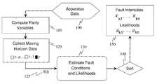
- the methodcomprises the following four steps. Step 1: processing data from the sensors to obtain a set of parameters y, known as parity parameters, which reflect apparatus condition deviation from normality.
- Step 2collecting the parity parameters y over a moving horizon interval of time of a fixed maximal duration and ending at time period t in a data vector Y(t);
- Step 3computing estimates of the fault conditions and likelihood parameters for each of the fault conditions;
- Step 4transmitting the computed estimates of the fault conditions to a display device or to an automated decision and control system or storing the computed estimates in memory.
- Step 1parameters y might be obtained from the sensor data as prediction residuals: differences of the observed sensor readings and the readings predicted for apparatus model which receives the same inputs as the apparatus.
- Different types of the apparatus modelcan be used such as a dynamic model, a nonlinear map, a set of static values corresponding to a chosen steady state regime, or another computer simulation model of the apparatus.
- the fault condition k at time period twhich is estimated at Step 3, is characterized by fault intensity parameter x k (t) and the fault signature corresponding to the fault condition k is known at the time of the method application.
- the fault signaturescan be obtained as responses observed in the data y when a fault occurs or as approximations of such responses.
- the computation of diagnostic estimates for faultscomprises computing estimates of the fault intensity parameters x k (t) over the moving horizon interval of time and likelihood parameters p k for each fault condition k.
- Step 3 computationsare done for one fault condition k at a time in two sub-steps: first by employing a ‘formulator’ and then by employing an ‘optimizer’.
- the formulatoris a software module, which formulates a convex optimization program for fault condition using the moving horizon data vector Y(t).
- the optimizeris a software module, which numerically finds the solution of the convex optimization program encoded by the formulator; the solution is computed with a pre-defined accuracy for fault condition k.
- the convex program for the fault conditioncan include additional decision variables in addition to the fault intensity parameters x k (t).
- the convex optimization program encoded by the formulator, and solved by the optimizercan have one of the known forms, for which efficient optimization solvers are known, such as an isotonic or monotonic regression program, a univariate convex program, a Quadratic Program, a Linear Program, a Second-order Cone Program.
- efficient optimization solverssuch as an isotonic or monotonic regression program, a univariate convex program, a Quadratic Program, a Linear Program, a Second-order Cone Program.
- These and many other types of constrained convex optimization programscan be efficiently solved using an interior-point method or other suitable convex optimization method.
- An important advantage of the proposed approachis that it could be set up to allow formulating and solving the convex optimization problem if one or more of the components of vector Y(t) is missing or unavailable.
- the diagnostic estimates for faults obtained at Step 3 and used at Step 4comprise estimates of fault condition intensity parameters x k (t) over the moving horizon interval of time computed as the optimal solution and likelihood parameters p k computed as the optimum value of the program.
- the fault condition parameters x k (t) and likelihood parameters p k computed by the optimizercan be used for determining one or several most likely candidate fault conditions (by sorting the likelihoods) and intensities of these conditions. This information can be employed for improving safety of the apparatus operation by halting or reconfiguring the operation in an event of the fault. The reconfiguration can be also used for improving apparatus performance. Alternatively, knowing which fault might have most likely occurred can be used for scheduling a correct maintenance action with reduced troubleshooting effort.
- the proposed methodcan be implemented on-line in a computer or computers connected to the sensors of the apparatus or it can be implemented off-line by collecting data from the apparatus, transmitting it by electronic means to a computer implementing the method, and performing the method computations at a later time.
- the present inventionalso encompasses a system for diagnostics of an apparatus; the system implements the proposed method.
- the inventionalso encompasses a software program product comprising computer readable media implementing the proposed method.
- the proposed method, or a system implementing the method, or a software program product implementing the methodare generic and with proper adjustment, tuning, configuration, and integration can be used in many different applications for many types of apparatuses.
- Three possible embodiments of the method described in detail belowinclude monitoring solid rocket motor of launch vehicle for improving safety of manned space flight, monitoring jet engines to improve aircraft servicing and maintenance, and monitoring semiconductor manufacturing tool to improve its performance.
- the proposed inventioncan be used in many additional applications. These applications include but are not limited to heating, ventilation, and air conditioning equipment, chillers, and refrigerators; oil drilling rigs; various aircraft systems, including the propulsion system; ground vehicles (cars, tracks, and military vehicles) and their systems; industrial manufacturing processes, such as refineries and pulp and paper plants; and other.
- a convex program formulated by the formulator and solved by the optimizeris guaranteed to have a single global solution that can be efficiently computed.
- a convex programcan be solved very fast, especially for specialized forms of such problem that are described in detailed description below.
- such solutioncan be implemented in a real-time system.
- the methodcan accommodate nonlinearities by employing models obtained by linearization at different conditions as separate fault models; an example is discussed in the detailed description.
- the methodincludes computation of the fault state likelihood as a byproduct of the optimization; this enables computing fault ambiguity group by sorting the likelihoods and thresholding them.
- the methodcan accommodate missing data; this can be done by formulator dropping the terms with the missing data in the optimization problem
- FIG. 1is a block diagram which illustrates functionality of a representative monitoring and control system implementing the method proposed by this invention.
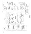
- FIG. 2is a block diagram which depicts overall functionality and component parts (steps) of the method proposed by this invention.
- FIG. 3is a block diagram which depicts overall functionality and component parts (steps) of the optimization based estimation algorithm in the center of the method proposed by this invention.
- FIG. 4is a schematic picture illustrating the augmentation force and moment for the crew launch vehicle thrust augmentation fault.
- FIG. 5is a block diagram which illustrates computation of angular and linear acceleration residuals as parity variables for the crew launch vehicle.
- FIG. 6is a schematic picture which illustrates the discretized fault modeling for the crew launch vehicle thrust augmentation.
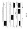
- FIG. 7is a chart which shows simulation results for the flight of crew launch vehicle with a case breach fault including angular and linear accelerations and the angular and linear acceleration residuals.
- FIG. 8is a chart which shows negative log-likelihood plots for different fault hypothesis corresponding to the simulation results in FIG. 7 .
- FIG. 9is a block diagram which illustrates diagnostic estimation for a turbine engine.
- FIG. 10is a chart which shows example results of diagnostic estimation for a turbine engine.
- FIG. 11is a chart which illustrates fault signatures for etching tool.
- FIG. 12is a chart which illustrates run to run data with faults for etching tool.
- FIG. 13is a chart which illustrates estimated fault intensity and seeded fault for etching tool.
- FIG. 14is a block diagram that illustrates an embodiment of a computer/server system upon which an embodiment of the inventive methodology may be implemented.
- This inventionclaims a method for diagnostic estimation of fault states of an apparatus; the method can be implemented as a part of monitoring system or as a software program product.
- the proposed fault diagnostics methodis preferably implemented in software and can be adapted to work with different types of applications (faults, apparatuses, and systems) by changing initial data processing step of the method, fault signatures used in the method, and other configurable parts of the method.
- the embodiments described belowdescribe examples of the apparatuses for which this method can be implemented; the method is not limited to these example apparatuses.
- FIG. 1 , FIG. 2 , and FIG. 3each relate to all preferred embodiments described below.
- FIG. 1illustrates a preferred embodiment with diagnostics system 10 receiving data from apparatus 20 and providing the fault state estimates to fault tolerance system 20 and decision support system 90 .
- Apparatus 20can be any engineering system: propulsion system, engine, ground, air, space, or water vehicle, machine, device, electrical power system, semiconductor manufacturing tool, HVAC equipment, computer network, etc.
- apparatus 20is propulsion system of a rocket launch vehicle (rocket motor) or of an aircraft (jet engine).
- apparatus 20is a semiconductor manufacturing tool, such as an etch tool.
- the proposed inventionis applicable to different types of system including but not limited to the systems described in detail below.
- Diagnostic system 10implements the proposed method and can be any suitable programmable computing device such as a general-purpose desktop computer, mainframe computer, server, avionics module, engine control unit, embedded processor, or FPGA device.
- Apparatus 20includes one or more sensors 30 ; it could also include one or more actuators 40 .
- Embedded electronics 50interfaces with sensors 30 and actuators 40 .
- Embedded electronics 50also interfaces with control system 60 , which would be normally implemented in an embedded computer, and with diagnostic system 10 . Some of the sensors 30 could be used for diagnostics only and not used by control system 60 .
- the diagnosed fault state of the system or determined ‘no fault’ stateis transmitted to fault tolerance system 80 , which might perform system reconfiguration, such as switching to backup hardware, or implementing a mission management action, such as mission re-planning.
- FIG. 1shows fault tolerance system 80 interfaced with control system 60 .
- Control system commands that influence apparatus 20are also transmitted to diagnostic system 10 .
- the diagnosed fault state of the systemis transmitted to decision support system 90 , which processes the diagnostic estimates and prepares operator advisory information to be shown in operator display 70 .
- the displayed advisorycan be used for on-line decision, e.g., by an aircraft pilot or a tool operator, or off-line, e.g., by maintenance personnel for deciding which of the plurality of possible maintenance and troubleshooting actions should be undertaken.
- FIG. 2illustrates the preferred embodiment of the diagnostics system 10 in more detail.
- the systemis engaged periodically at a time period that is known.
- FIG. 2illustrates performance of diagnostic system 10 at time period with a sequential number t.
- Apparatus data 100which serve as the input, include the data obtained by diagnostics system 10 from embedded electronics 50 of the apparatus and from control system 60 .
- Apparatus data 100are used to compute parity variables 110 .
- parity variablesare herein defined as such transformations of the apparatus data, which are supposed to be zero according to the model of the apparatus nominal operation.
- the parity variablesare the differences between the predicted and actually measured accelerations of the rocket.
- the parity variablescomprise the differences between the actual engine output data and the data predicted based on the engine model, which has the same inputs as the actual engine; the parity variables further comprise discrete fault flags computed by lower-level fault detection logic.
- the parity variablesare the deviations of the measured variables from the set values in the recipe.
- the parity variablesare collected in a moving horizon data set Y(t) 125 , which includes the parity variables obtained over the horizon of length of last n time periods of the diagnostic estimation.
- the data computed at the previous cyclesare stored in the memory 120 and included into the moving horizon data set 125 .
- An important and useful feature of the proposed inventionis that is can be used even if a part of the data in the set 125 is missing; the data can be missing because the sensors readings are lost or unavailable to diagnostics system or because some sensors fail.
- the moving horizon length ncan be determined as a part of system engineering tradeoffs; the proposed invention does can be implemented with different lengths n of the moving horizon.
- Data set Y(t) 125serves as the main input into estimation of fault condition and likelihoods 130 ; the said estimation is detailed in FIG. 3 and the description of FIG. 3 below.
- the proposed methoddetermines which fault state actually exists and what fault intensity is.
- Estimation 130produces an output data set 150 that includes fault intensity parameter vectors X k and likelihood values p k for each of the K possible fault states.
- Sorter 140ranks the estimates in the order of decreasing likelihood and selects a short list of the faults that are most likely to have occurred.
- the short listis also known as an ambiguity group. If the apparatus is determined to be in the ‘no-fault’ state, the ambiguity group contains no (zero) faults states.
- the short listincludes data for the faults with the likelihoods above a given threshold.
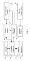
- FIG. 3illustrates the preferred embodiment of the method for batch estimation 130 from the moving horizon data Y(t) 125 at a given time period t of operation of diagnostics system 10 .
- Faults signatures 210are shown as an additional input to the estimation.
- the first preferred embodimentthe SRM case breach detection
- fault signatures 210can be computed based on fault number using a simple formula.
- the second preferred embodimentthe turbine engine diagnostics
- fault signatures 210are computed using a model of the engine.
- fault signatures 210are computed off-line from the historical fault data and are stored in a table.
- the estimation computations 230start by performing initialization 200 .
- the initializationincludes computing likelihood of the ‘no-fault’ hypothesis.
- the computationsare performed in cycle 230 for one fault condition at a time.
- fault signature S k 245is obtained by selector 285 from fault signatures 210 .
- Data Y(t) 125 and fault signature S k 245are provided as inputs to formulator 240 .
- An output of formulator 240is a convex program for the optimal estimation of the fault intensity parameter vector X k and vector of additional decision variables U.
- Uincludes the hidden states of the system that need to be determined along with X.
- Formulator 240sets up the structure and parameters of the program such as matrices, vectors, and parameters of the optimized loss function and constraints.
- the loss function for fault k denoted as L kis the negative log-likelihood index for a posteriori probability of fault k.
- the loss indexis ⁇ log P ( X k ,U
- Y )⁇ log P ( Y
- X k ,U)is known as observation model, and the conditional probability P(X k ,U) is known as prior model.
- the loss index L k (X k , U)⁇ log P(X k ,U
- the problem of fault estimationcan be stated as minimize L k ( X k ,U ) (2) subject to ⁇ X k ,U ⁇ (3).
- loss index L k (X k ,U)depends on the fault stochastic model and has significant degree of flexibility.
- the proposed inventionrequires the loss index L k (X k ,U), which is a convex function.
- the loss indexis defined in a convex domain , which reflects the known constraints on the decision variables X k and U.
- the inventionis not limited to one particular type of the loss index (2) and one particular set of constraints (3). It includes the preferred embodiments of (2)-(3) that are discussed below; it also includes different combinations and extensions of these embodiments that yield convex problems of the form (2)-(3) as anyone versed in the art would recognize.
- a specific choice of the optimization problem formulation and of the parameters of such formulationis a matter of detailed system engineering, such detail are outside of what is claimed by this invention.
- a detailed formulationcan be taken from the published literature or established for the system in hand in a custom way.
- v(t)is independent identically distributed process noise sequence.
- w(t)follows a Gaussian distribution and v(t) follows a one-sided exponential distribution.
- convex problem (2)-(3)of the following specific form minimize 1 ⁇ 2Q ⁇ t [y(t) ⁇ S k x(t)] 2 +R ⁇ t [x(t) ⁇ x(t ⁇ 1)], (8) subject to x ( t ⁇ 1) ⁇ x ( t ) ⁇ 0, (9)
- x 1 (t)can have a meaning of primary damage and x 2 (t) has a meaning of secondary damage, which is observable through y(t); the rate of the secondary damage accumulation is proportional to the primary damage intensity at that time.
- the values x 2 (t) in the model (10)-(12)contribute to the vector X k (5) and the values x 1 (t) are included into the vector U of additional decision parameters in the problem (2)-(3).
- v(t) and w(t)are either gaussian, or uniform bounded, or Laplacian, or one-sided exponential noises in the first-order model (6)-(7), the second-order model (8)-(10), or in other linear state-space models with additive noises that might be used to formulate the probabilistic models in (1).
- the second preferred embodimentconsiders a probabilistic formulation where some of the observed parity variables y(t) are discrete variables taking values 0 or 1 only. Such discrete variables correspond to fault warning flags known as BIT (Built-in-test) flags generated by low-level electronics hardware or software in a majority of embedded control and monitoring systems.
- BITBusilt-in-test
- Formulation (14)models sensor failure that is manifested as a sensor offset and also might cause a BIT fault flag to be set.
- Formulations (13) and (14)yield convex terms ⁇ log P(Y
- ⁇is a cumulative probability density function for the normal distribution with unit covariance
- qis the standard deviation of the zero-mean Gaussian noise w(t) and functions of the vectors are computed component-wise.
- the embodiments discussed in some detail above and other possible embodiments of this inventionformulate the fault state estimation problem as convex optimization problem (2)-(3).
- the convexity of problem (2)-(3)provides a guarantee that a global optimal solution X k of the problem (2)-(3) can be efficiently computed using an optimizer 250 .
- One embodimentemploys optimizer using an interior-point method.
- Another embodimentimplements the method by using commercially available convex optimizers/solvers such as Mosek or SeDuMi.
- convex optimizers/solverssuch as Mosek or SeDuMi.
- There are existing optimizers that solve the convex problems of the well-known classessuch as QP, Linear Program (LP), Second-Order Conic Program (SOCP), and other such.
- optimizer 250is shown to provide the fault state estimate X and the likelihood p as the outputs 260 .
- the vector Xis obtained as an optimal decision vector in the optimization problem (2)-(3) or is made of some components of the optimal decision vector.
- the likelihood value pis obtained as an optimal value of the log-likelihood index in the optimization problem (2)-(3) or as a simple transformation of such optimal value.
- the log-likelihood ratiois converted to probabilistic likelihood by taking an exponent to convert from log-probabilities to probabilities and then multiplying by a scaling factor to normalize the probabilities of the complementary events such that they add up to one.
- the obtained estimates X and p 260are added to the set of the accumulated estimates 275 and the computations 230 are repeated for the next fault 280 until all the faults are exhausted 290 . After the completion of the computations 295 , accumulated estimates 275 are included with the outputs of the diagnostic system 10 .
- the first preferred embodiment of the inventionis discussed below in regard to early detection of Solid Rocket Motor (SRM) case breach detection for crew launch abort in a crew launch vehicle.
- SRMSolid Rocket Motor
- FIG. 4illustrates the case breach fault 305 in the first stage SRM 300 of a CLV;
- T A 310is the thrust augmentation force,
- d 320is the distance between the case breach location and the rocket center-of-gravity (CG),
- M Z 315is the tilting moment created by the force T A 310 that is aligned with the lateral axis y.
- the attached axisis longitudinal and axis z complements y and x.
- the method of the proposed inventionis aimed at accurate and fast detection of the case breach fault using Guidance Navigation and Control (GN&C) sensors available on board of the rocket.
- GN&CGuidance Navigation and Control
- the diagnostic systemis implemented in the vehicle on-board avionics and performs automated decision on initialing crew abort; if sufficient time is available the diagnostic estimated could be presented to the pilot display for the pilot to make the decision to abort the mission and eject crew capsule 325 .
- the diagnostic systemtransmits the data to the ground mission management operators who would make the decision. Both embodiment implement the proposed invention; the applicability is defined by acceptable decision delay.
- the problem of case breach fault estimationis highly nonlinear; the location of the breach and the breach intensity are unknown. The proposed invention allows addressing this problem.
- FIG. 5illustrates computation of parity variables 350 in this embodiment, which is the first step in applying the proposed method.
- the vehicle data used for the parity variable computationsare comprised of 6 accelerations (3 rotational and 3 linear), 3 linear velocities, 3 angular rates, 3 attitude angles, altitude (for characterizing air flow), 2 TVC gimbal angles, and flight time (for scheduling).
- Instantaneous values of linear and angular accelerationsare measured by accelerometers in an IMU (inertial measurement unit) of the vehicle.
- IMUintial measurement unit
- the flow of the computationsis illustrated in FIG. 5 .
- One shown input to the computationsis the vector of six accelerations 355 .
- Another shown input 360collects the remaining sensor channels describing the dynamical states of the vehicle rigid-body model.
- the flight dynamics modelis used to compute the total moments and forces acting on the vehicle in the attached coordinate axes 365 . Knowing the vehicle inertia tensor and the vehicle mass, the three angular and three linear accelerations of the vehicle in the attached axes are calculated from Euler's equations and Newton's law. The computed accelerations are subtracted 370 from the measured accelerations 355 to yield the 6-component acceleration residual vector y(t) 375 . In this embodiment the parity variables are the acceleration residuals. Based on the model they should be zero if there is no fault. In fact, they are impacted by sensor noise, thrust variation, airflow turbulence, and modeling errors. To obtain the moving horizon data set 125 , the acceleration residuals y(t) 375 are collected over the horizon of length n as described by ( 4 ).
- FIG. 6illustrates the fault model in this embodiment.
- the thrust augmentationis specified by three parameters: magnitude x(t) 380 , circumferential angle of the case breach location, ⁇ A 390 , and longitudinal coordinate of the breach location d A 385 .
- the case breachcan be located in a continuum of possible locations, the preferred embodiment of this invention assumes that it is located in one of K discrete locations 395 illustrated in FIG. 6 .
- Fault signature models for each of the discrete locationsare computed based on the geometry as follows.
- the thrust augmentation magnitude T Ax(t) 380 is an time-dependent unknown variable.
- a MAP estimate of x(t) from the datais obtained used within H k .
- the null (‘no-fault’) hypothesis H 0assumes that there is no fault and x(t) ⁇ 0. Diagnostic system 10 must determine which of the fault hypothesis holds: whether the fault has occurred and, if yes, what is the fault location index k.
- the fault data vector X khas form (6).
- Probabilistic model (1) for the indexcomprises the prior monotonic random walk model of the form (7), where v(t) is one-sided exponentially distributed noise. Such model reflects the prior knowledge that the breach grows irreversibly.
- Probabilistic model (1)further comprises observation model of the form (6) where the fault signature can be calculated as the effect of the thrust augmentation force 385 in FIG. 6 on the acceleration residuals 375 .
- mis the rocket mass
- I zz and I yyare the main moments of inertia
- p Ais a nondimensional coefficient describing the longitudinal thrust decrease in proportion to the lateral thrust augmentation.
- the probabilistic model (6)-(7), (18)yields the convex optimization problem formulation (8)-(9), which is an isotonic regression problem.
- This problemcan be efficiently and very quickly solved by a convex optimizer 250 implementing one of the known linear-time isotonic regression solutions, such as the PAVA algorithm.
- FIG. 6illustrates simulation results.
- the simulationincluded 6-DOF (degree-of-freedom) kinematics and dynamics, TVC actuator model, aerodynamic tables obtained from CFD analysis, SRM thrust augmentation, and a 10% random variation of the SRM thrust, which creates acceleration jitter.
- a case breach faultwas introduced as a ramp starting at simulation time 10 sec and reaching a steady state value at time 16 sec.
- FIG. 7shows the six accelerations 355 as dashed lines 400 , 405 , 410 (angular accelerations), and 415 , 420 , 425 (linear accelerations). Acceleration residuals 375 are shown as solid lines 430 , 435 , 440 (the angular) and 445 , 450 , 455 (the linear).
- the proposed methodcorrectly estimated the magnitude and location of the seeded fault with a 1.5 sec delay after the start of the ramp.
- the proposed methodprovided for a superior quality of estimation. The correct location and intensity of the case breach were determined reliably and fast despite the substantial noise contamination of the data.
- FIG. 8illustrates the estimation results obtained with the proposed method by showing the traces of the loss indexes computed at each time step.
- the solid line 460shows the point-wise minimum for all fault hypotheses, min k L k .
- the upper dashed curve 465shows the loss index L o for the ‘no-fault’ hypothesis.
- the faultis detected when the solid line 460 crosses the triangle marked line 470 .
- the algorithmhad very good computational performance with the computation time of a few milliseconds on a PC computer.
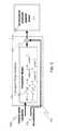
- FIG. 9illustrates the process of diagnostic estimation for a turbine engine with the proposed method.
- Turbine engine 500is equipped with electronic control unit 510 , which is interfaced with the engine sensors.
- FIG. 9shows that the functionality of electronic control unit 510 includes estimation of engine efficiency parameters 515 ; this estimation yields deviations of the engine efficiency parameters, such as compressor efficiency, turbine efficiency, etc, from the nominal values.
- the outputs u(t) of parameter estimation 515are considered as parity parameters 525 .
- Electronic control unit 510further includes BIT functions and BIT processing logic shown as a block 520 that estimates discrete fault flags and generates fault codes z(t) 530 .
- the codes z(t)are zero (or absent) in the absence of faults and can be considered as discrete parity parameters.
- the diagnostic systemproduces the estimates 540 of the fault condition intensities X k1 , . . . X kn and likelihood parameters p k1 , . . . p kn for each of the candidate fault conditions.
- the estimates 540are obtained by module 535 as the maximum posteriori probability estimates (1).
- the optimization program 250 (2)-(3)is formulated 230 by using observation models of the form (6) for the continuous components of the parity vector y(t) ( 18 ) and observation models of the form (13) for the discrete components of vector y(t) (18).
- Fault signatures 210are available from a detailed simulation model of the engine.
- Gaussian priorsare used for the fault intensity: x ⁇ x k N(m k ,R k ), where index k numbers components of vector Y(t) ( 18 ) and fault types.
- an optimization problem (2)is formulated by formulator 230 ; there are no constraints (3).
- the log-likelihood optimization problem solved by optimizer 250has a single decision parameter: fault intensity x k .
- the problemis convex and the optimal solution is obtained by optimizer using a dichotomy algorithm to find the zero of the gradient of the loss index.
- the computed estimates 150 of the turbine engine fault conditionsare transmitted to a display device 70 through a decision support system 90 , or to an automated decision and control system 80 , or stored in memory for subsequent transmission and analysis.
- the diagnostic estimatescan be performed by software implemented in on-board avionics attached to the engine. The estimates can be used during the flight as a pilot warning and/or stored till the end of the flight. The diagnostic estimates can be also performed in on-ground computers that receive sensor data snapshots obtained during the flight. The ground processing would indicate a possibility of a particular fault and provide maintenance guidance.
- FIG. 10illustrates results for the method implemented for a detailed simulation of a military engine.
- the following diagnostic reportwas obtained for data in FIG. 10 .
- the third preferred embodimentis discussed below with respect to a semiconductor manufacturing tool. Though the specific discussion is for an etch tool, one versed in the art would recognize its full applicability to other tools, including but not limited to a CVD (chemical vapor deposition) tool, CMP (chemical-mechanical polishing), ion beam implantation, lithography tools, and other tools used in semiconductor manufacturing.
- CVDchemical vapor deposition
- CMPchemical-mechanical polishing
- ion beam implantationion beam implantation
- lithography toolslithography tools
- ICintegrated circuits
- Such toolsare complex machines equipped with multiple sensors 30 , actuators 40 , and embedded electronics 50 .
- Control system 60 of such toolis operating at two time scales. At the fast time scale is the tool is controlled and monitored while processing a single batch of silicon wafers. At a slower time scale, the tool is controlled and monitored from run to run; this is known as R 2 R control.
- diagnostics system 10processes the data obtained over multiple runs. In this embodiment, the time period t is the sequential run number. The diagnostic estimates are transmitted into a decision support system 90 that provides maintenance recommendations for the tool through operator display 70 .
- the semiconductor manufacturing toolsusually implement a fixed recipe for long periods of time.
- tool R 2 R data 100are used to compute parity variables 110 as deviations of the monitored parameters from the recipe.
- An example of the third preferred embodimentis discussed below is its implementation for an etch tool.
- An engineering design of the diagnostic and monitoring systemrequires a selection of the monitored variables and selection of the fault parameters to be estimated. Such selection is driven by fault frequency and impact as well as by ability to estimate the faults from the monitored variables. The selection is outside of the method proposed by this invention.
- For the etch tool examplewe consider the following four monitored variables: ‘REFLECTED RF POWER’, ‘ELECTRODE COOLING TEMPERATURE’, ‘PRESSURE CONTROL VALVE’, and ‘ENDPOINT DETECTOR’. The deviations of these variables from the recipe at run t comprise the observation vector y(t).
- the proposed diagnostic estimation methodmonitors (and estimated the intensity of) the following three potential faults: ‘HIGH REFLECTED RF POWER’, ‘LOWER ELECTRODE TEMPERATURE’, and ‘CHAMBER LEAK’.
- the intensities of these faultscorrespond to deviations of the respective parameters from their recipe values and comprise the fault vector x(t).
- FIG. 11illustrates the fault signatures S k relating y(t) and x(t) in accordance with (6).
- the upper plot 600 in FIG. 11illustrates the fault signature S 1 for ‘HIGH REFLECTED RF POWER’ fault.
- the middle plot 605 in FIG. 11illustrates the fault signature S 2 for ‘LOWER ELECTRODE TEMPERATURE’ fault.
- the lower plot 610 in FIG. 11illustrates the fault signature S 2 for ‘LOWER ELECTRODE TEMPERATURE’ fault.
- the bar heightillustrates the value of the signature vector component.
- the bar numberscorrespond to the monitored variables: 620 bar 1 to ‘REFLECTED RF POWER’, 625 bar 2 to ‘ELECTRODE COOLING TEMPERATURE’, 630 bar 3 to ‘PRESSURE CONTROL VALVE’, and 635 bar 4 to ‘ENDPOINT DETECTOR’.
- the moving horizon data Y(t) 125 of the form (4)is provided as one of the inputs to formulator 230 .
- Another inputis the fault signature S k illustrated in FIG. 11 ; a different signature at each cycle k 200 , 280 , 290 , 285 , 295 .
- the problem (19)-(20)is a QP program and can be solved by using a standard QP solver in optimizer 250 .
- FIG. 12depicts four data plots as a function of run number, including reflected RF power 640 , lower electrode temperature 645 , pressure control valve 650 and endpoint detector 655 .
- FIG. 12illustrates example R 2 R data for etch tool; the tool experiences a fault which is reflected in the data but is difficult to detect without data processing.
- the computed decision vector X 2 comprised of the fault estimate time series x 2 (t) 665is illustrated in FIG. 13 in comparison with the seeded fault time series 660 .
- FIG. 13shows that the seeded fault 660 at the last time period and the seeded fault time series 665 over previous time periods t are estimated with good accuracy from the noisy data.
- HVACheating, ventilation, and air conditioning equipment
- air conditionersheating, ventilation, and air conditioning equipment
- heatersheaters, chillers, and refrigerators
- oil drilling rigsaircraft systems
- ground vehiclescars, tracks, and military vehicles
- industrial manufacturing processessuch as refineries and pulp and paper plants; and other.
- FIG. 14is a block diagram that illustrates an embodiment of a computer/server system 1400 upon which an embodiment of the inventive methodology may be implemented.
- the system 1400includes a computer/server platform 1401 , peripheral devices 1402 and network resources 1403 .
- Perifieral devices 1402may be absent if computer system 1400 is implemented as an embedded system, e.g., as an embedded control and monitoring system which is integrated with the apparatus.
- the computer platform 1401may include a data bus 1404 or other communication mechanism for communicating information across and among various parts of the computer platform 1401 , and a processor 1405 coupled with bus 1404 for processing information and performing other computational and control tasks.
- Computer platform 1401also includes a volatile storage 1406 , such as a random access memory (RAM) or other dynamic storage device, coupled to bus 1404 for storing various information as well as instructions to be executed by processor 1405 .
- the volatile storage 1406also may be used for storing temporary variables or other intermediate information during execution of instructions by processor 1405 .
- Computer platform 1401may further include a read only memory (ROM or EPROM) 1407 or other static storage device coupled to bus 1404 for storing static information and instructions for processor 1405 , such as basic input-output system (BIOS), as well as various system configuration parameters.
- ROMread only memory
- EPROMelectrically erasable read-only memory
- a persistent storage device 1408such as a magnetic disk, optical disk, or solid-state flash memory device is provided and coupled to bus 1404 for storing information and instructions.
- Computer platform 1401may be coupled via bus 1404 to a display 1409 , such as a cathode ray tube (CRT), plasma display, or a liquid crystal display (LCD), for displaying information to a system administrator or user of the computer platform 1401 .
- a display 1409such as a cathode ray tube (CRT), plasma display, or a liquid crystal display (LCD), for displaying information to a system administrator or user of the computer platform 1401 .
- An input device 1410is coupled to bust 1404 for communicating information and command selections to processor 1405 .
- cursor control device 1411is Another type of user input device.
- cursor control device 1411such as a mouse, a trackball, or cursor direction keys for communicating direction information and command selections to processor 1404 and for controlling cursor movement on display 1409 .
- This input devicetypically has two degrees of freedom in two axes, a first axis (e.g., x) and a second axis (e.g.
- An external storage device 1412may be connected to the computer platform 1401 via bus 1404 to provide an extra or removable storage capacity for the computer platform 1401 .
- the external removable storage device 1412may be used to facilitate exchange of data with other computer systems.
- the inventionis related to the use of computer system 1400 for implementing the techniques described herein.
- the inventive systemmay reside on a machine such as computer platform 1401 .
- the techniques described hereinare performed by computer system 1400 in response to processor 1405 executing one or more sequences of one or more instructions contained in the volatile memory 1406 .
- Such instructionsmay be read into volatile memory 1406 from another computer-readable medium, such as persistent storage device 1408 .
- Execution of the sequences of instructions contained in the volatile memory 1406causes processor 1405 to perform the process steps described herein.
- hard-wired circuitrymay be used in place of or in combination with software instructions to implement the invention.
- embodiments of the inventionare not limited to any specific combination of hardware circuitry and software.
- Non-volatile mediaincludes, for example, optical or magnetic disks, such as storage device 1408 .
- Volatile mediaincludes dynamic memory, such as volatile storage 1406 .
- Computer-readable mediainclude, for example, a floppy disk, a flexible disk, hard disk, magnetic tape, or any other magnetic medium, a CD-ROM, any other optical medium, punchcards, papertape, any other physical medium with patterns of holes, a RAM, a PROM, an EPROM, a FLASH-EPROM, a flash drive, a memory card, any other memory chip or cartridge, a carrier wave as described hereinafter, or any other medium from which a computer can read.
- Various forms of computer readable mediamay be involved in carrying one or more sequences of one or more instructions to processor 1405 for execution.
- the instructionsmay initially be carried on a magnetic disk from a remote computer.
- a remote computercan load the instructions into its dynamic memory and send the instructions over a telephone line using a modem.
- a modem local to computer system 1400can receive the data on the telephone line and use an infra-red transmitter to convert the data to an infra-red signal.
- An infra-red detectorcan receive the data carried in the infra-red signal and appropriate circuitry can place the data on the data bus 1404 .
- the bus 1404carries the data to the volatile storage 1406 , from which processor 1405 retrieves and executes the instructions.
- the instructions received by the volatile memory 1406may optionally be stored on persistent storage device 1408 either before or after execution by processor 1405 .
- the instructionsmay also be downloaded into the computer platform 1401 via Internet using a variety of network data communication protocols well known in the
- the computer platform 1401also includes a communication interface, such as network interface card 1413 coupled to the data bus 1404 .
- Communication interface 1413provides a two-way data communication coupling to a network link 1414 that is connected to a local network 1415 .
- communication interface 1413may be an integrated services digital network (ISDN) card or a modem to provide a data communication connection to a corresponding type of telephone line.
- ISDNintegrated services digital network
- communication interface 1413may be a local area network interface card (LAN NIC) to provide a data communication connection to a compatible LAN.
- Wireless linkssuch as well-known 802.11a, 802.11b, 802.11g and Bluetooth may also used for network implementation.
- one of the standard backplane data busessuch as, ARINC 629 or an optical avionics data bus may be used.
- a TTP data busmay also be used, such as in automotive and aerospace applications.
- communication interface 1413sends and receives electrical, electromagnetic or optical signals that carry digital data streams representing various types of information.
- Network link 1413typically provides data communication through one or more networks to other network resources.
- network link 1414may provide a connection through local network 1415 to a host computer 1416 , or a network storage/server 1422 .
- the network link 1413may connect through gateway/firewall 1417 to the wide-area or global network 1418 , such as an Internet.
- the computer platform 1401can access network resources located anywhere on the Internet 1418 , such as a remote network storage/server 1419 .
- the computer platform 1401may also be accessed by clients located anywhere on the local network 1415 and/or the Internet 1418 .
- the network clients 1420 and 1421may themselves be implemented based on the computer platform similar to the platform 1401 .
- Local network 1415 and the Internet 1418both use electrical, electromagnetic or optical signals that carry digital data streams.
- the signals through the various networks and the signals on network link 1414 and through communication interface 1413 , which carry the digital data to and from computer platform 1401 ,are exemplary forms of carrier waves transporting the information.
- Computer platform 1401can send messages and receive data, including program code, through the variety of network(s) including Internet 1418 and local network 1415 , network link 1414 and communication interface 1413 .
- network(s)including Internet 1418 and local network 1415 , network link 1414 and communication interface 1413 .
- system 1401when the system 1401 acts as a network server, it might transmit a requested code or data for an application program running on client(s) 1420 and/or 1421 through Internet 1418 , gateway/firewall 1417 , local network 1415 and communication interface 1413 . Similarly, it may receive code from other network resources.
- the received codemay be executed by processor 1405 as it is received, and/or stored in persistent or volatile storage devices 1408 and 1406 , respectively, or other non-volatile storage for later execution.
- computer system 1401may obtain application code in the form of a carrier wave.
Landscapes
- General Physics & Mathematics (AREA)
- Engineering & Computer Science (AREA)
- Physics & Mathematics (AREA)
- Mathematical Analysis (AREA)
- Evolutionary Computation (AREA)
- Artificial Intelligence (AREA)
- Algebra (AREA)
- Mathematical Optimization (AREA)
- Mathematical Physics (AREA)
- Probability & Statistics with Applications (AREA)
- Pure & Applied Mathematics (AREA)
- Automation & Control Theory (AREA)
- Testing And Monitoring For Control Systems (AREA)
Abstract
Description
−logP(Xk,U|Y)=−logP(Y|Xk,U)−logP(Xk,U)+c (1)
minimizeLk(Xk,U) (2)
subject to {Xk,U}ε

Y(t)=col[y(t−n) . . .y(t)], (4)
Xk=col[x(t−n) . . .x(t)], (5)
y(t)=Skx(t)+w(t), (6)
x(t+1)=x(t)+v(t), (7)
minimize ½QΣt[y(t)−Skx(t)]2+RΣt[x(t)−x(t−1)], (8)
subject tox(t−1)−x(t)≦0, (9)
y(t)=Skx2(t)+w(t), (10)
x1(t+1)=x1(t)+v1(t), (11)
x2(t+1)=x1(t)+x2(t)+v2(t), (12)
y(t)=θ1[Skx(t)+w(t)], (13)
y(t)=θ1[|Sx(t)+w(t)|], (14)
−logP(y=1|x)=−log(2−Φ[(1−Skx)/q]−Φ[(1+Skx)/q]), (15)
−logP(y=0|x)=−log(1+Φ[(1−Skx)/q]+Φ[(1+Skx)/q]), (16)
Hk:{βA=βA,k;dA=dA,k}(k=1, . . . ,K) (17).
- In the second preferred embodiment the moving horizon has length one, only the data from the last time period are considered.
Data vector 125 combines the continuous and discrete parity parameters.
- In the second preferred embodiment the moving horizon has length one, only the data from the last time period are considered.
| Fault | Likelihood | Intensity | ||
| FAULT #1 | p = 0.587 | x = 0.109 | ||
| FAULT #2 | p = 0.413 | x = 0.052 | ||
| NO FAULT | p = 0.000 | x = 0 | ||
- The optimization problem formulated by
formulator 230 is based on the trend model of the form (10)-(12). This model assumes that process noise v2(t)=0 and process noise v1(t) is Laplacian with covariance R. The model leads to a MAP negative log-likelihood index L=L(Xk,U), where Xk=col[x2(t−n) . . . x2(t)] and U=col[x1(t−n) . . . x1(t)]. The formulated index optimization problem has the form
minimize ½Σt[∥y(t)−Skx2(t)∥Q]2+RΣt[x1(t)−x1(t−1)], (19)
subject tox2(t)=x1(t−1)+x2(t−1) (20).
- The optimization problem formulated by
Claims (24)
Priority Applications (1)
| Application Number | Priority Date | Filing Date | Title |
|---|---|---|---|
| US12/268,357US8121818B2 (en) | 2008-11-10 | 2008-11-10 | Method and system for diagnostics of apparatus |
Applications Claiming Priority (1)
| Application Number | Priority Date | Filing Date | Title |
|---|---|---|---|
| US12/268,357US8121818B2 (en) | 2008-11-10 | 2008-11-10 | Method and system for diagnostics of apparatus |
Publications (2)
| Publication Number | Publication Date |
|---|---|
| US20100121609A1 US20100121609A1 (en) | 2010-05-13 |
| US8121818B2true US8121818B2 (en) | 2012-02-21 |
Family
ID=42165999
Family Applications (1)
| Application Number | Title | Priority Date | Filing Date |
|---|---|---|---|
| US12/268,357Active2030-03-18US8121818B2 (en) | 2008-11-10 | 2008-11-10 | Method and system for diagnostics of apparatus |
Country Status (1)
| Country | Link |
|---|---|
| US (1) | US8121818B2 (en) |
Cited By (56)
| Publication number | Priority date | Publication date | Assignee | Title |
|---|---|---|---|---|
| US20090210104A1 (en)* | 2008-02-08 | 2009-08-20 | Airbus France | Process and device for diagnostic and maintenance operations of aircraft |
| US20110126063A1 (en)* | 2009-11-25 | 2011-05-26 | Renesas Electronics Corporation | Method for inserting test points for logic circuits and logic circuit testing apparatus |
| US20120004762A1 (en)* | 2009-03-16 | 2012-01-05 | Petra Bauer | Method for determining fittings for constant tables of automatic placement machines |
| US20120266649A1 (en)* | 2009-12-02 | 2012-10-25 | Michelin Recherche Et Technique S.A. | Method for detecting wear of a tyre |
| US20140129000A1 (en)* | 2012-11-06 | 2014-05-08 | General Electric Company | Systems and Methods For Dynamic Risk Derivation |
| US8744813B2 (en)* | 2008-11-28 | 2014-06-03 | Snecma | Detection of anomalies in an aircraft engine |
| US20140207290A1 (en)* | 2009-03-20 | 2014-07-24 | Johnson Controls Technology Company | Devices, systems, and methods for communicating with rooftop air handling units and other hvac components |
| US9235657B1 (en) | 2013-03-13 | 2016-01-12 | Johnson Controls Technology Company | System identification and model development |
| WO2015199779A3 (en)* | 2014-03-31 | 2016-03-17 | Peterson Elmor L | Flexible vector-processing algorithms for numerically solving extreme-scale, linear and non-linear, predictive and prescriptive, problems in science and engineering, on parallel-processing super computers |
| US20160215996A1 (en)* | 2015-01-26 | 2016-07-28 | Trane International Inc. | Diagnostic data bus for acquiring and communicating diagnostic information from hvac systems |
| US9436179B1 (en) | 2013-03-13 | 2016-09-06 | Johnson Controls Technology Company | Systems and methods for energy cost optimization in a building system |
| US9650934B2 (en) | 2011-11-04 | 2017-05-16 | Honeywell spol.s.r.o. | Engine and aftertreatment optimization system |
| US9659235B2 (en)* | 2012-06-20 | 2017-05-23 | Microsoft Technology Licensing, Llc | Low-dimensional structure from high-dimensional data |
| US9677493B2 (en) | 2011-09-19 | 2017-06-13 | Honeywell Spol, S.R.O. | Coordinated engine and emissions control system |
| US9852481B1 (en) | 2013-03-13 | 2017-12-26 | Johnson Controls Technology Company | Systems and methods for cascaded model predictive control |
| WO2018023363A1 (en)* | 2016-08-02 | 2018-02-08 | 邹霞 | Fault simulation system |
| US10036338B2 (en) | 2016-04-26 | 2018-07-31 | Honeywell International Inc. | Condition-based powertrain control system |
| US10101731B2 (en) | 2014-05-01 | 2018-10-16 | Johnson Controls Technology Company | Low level central plant optimization |
| US10124750B2 (en) | 2016-04-26 | 2018-11-13 | Honeywell International Inc. | Vehicle security module system |
| US10186889B2 (en) | 2015-10-08 | 2019-01-22 | Taurus Des, Llc | Electrical energy storage system with variable state-of-charge frequency response optimization |
| US10190789B2 (en) | 2015-09-30 | 2019-01-29 | Johnson Controls Technology Company | Central plant with coordinated HVAC equipment staging across multiple subplants |
| US10190793B2 (en) | 2015-10-08 | 2019-01-29 | Johnson Controls Technology Company | Building management system with electrical energy storage optimization based on statistical estimates of IBDR event probabilities |
| US10197632B2 (en) | 2015-10-08 | 2019-02-05 | Taurus Des, Llc | Electrical energy storage system with battery power setpoint optimization using predicted values of a frequency regulation signal |
| US10222427B2 (en) | 2015-10-08 | 2019-03-05 | Con Edison Battery Storage, Llc | Electrical energy storage system with battery power setpoint optimization based on battery degradation costs and expected frequency response revenue |
| US10235479B2 (en) | 2015-05-06 | 2019-03-19 | Garrett Transportation I Inc. | Identification approach for internal combustion engine mean value models |
| US10250039B2 (en) | 2015-10-08 | 2019-04-02 | Con Edison Battery Storage, Llc | Energy storage controller with battery life model |
| US10272779B2 (en) | 2015-08-05 | 2019-04-30 | Garrett Transportation I Inc. | System and approach for dynamic vehicle speed optimization |
| US10283968B2 (en) | 2015-10-08 | 2019-05-07 | Con Edison Battery Storage, Llc | Power control system with power setpoint adjustment based on POI power limits |
| US10309287B2 (en) | 2016-11-29 | 2019-06-04 | Garrett Transportation I Inc. | Inferential sensor |
| US10337964B2 (en)* | 2010-03-15 | 2019-07-02 | Klatu Networks, Inc. | Systems and methods for monitoring, inferring state of health, and optimizing efficiency of refrigeration systems |
| US10389136B2 (en) | 2015-10-08 | 2019-08-20 | Con Edison Battery Storage, Llc | Photovoltaic energy system with value function optimization |
| US10418833B2 (en) | 2015-10-08 | 2019-09-17 | Con Edison Battery Storage, Llc | Electrical energy storage system with cascaded frequency response optimization |
| US10418832B2 (en) | 2015-10-08 | 2019-09-17 | Con Edison Battery Storage, Llc | Electrical energy storage system with constant state-of charge frequency response optimization |
| US10415492B2 (en) | 2016-01-29 | 2019-09-17 | Garrett Transportation I Inc. | Engine system with inferential sensor |
| US10423131B2 (en) | 2015-07-31 | 2019-09-24 | Garrett Transportation I Inc. | Quadratic program solver for MPC using variable ordering |
| US10503128B2 (en) | 2015-01-28 | 2019-12-10 | Garrett Transportation I Inc. | Approach and system for handling constraints for measured disturbances with uncertain preview |
| US10554170B2 (en) | 2015-10-08 | 2020-02-04 | Con Edison Battery Storage, Llc | Photovoltaic energy system with solar intensity prediction |
| US10564610B2 (en) | 2015-10-08 | 2020-02-18 | Con Edison Battery Storage, Llc | Photovoltaic energy system with preemptive ramp rate control |
| US10594153B2 (en) | 2016-07-29 | 2020-03-17 | Con Edison Battery Storage, Llc | Frequency response optimization control system |
| US10621291B2 (en) | 2015-02-16 | 2020-04-14 | Garrett Transportation I Inc. | Approach for aftertreatment system modeling and model identification |
| US10700541B2 (en) | 2015-10-08 | 2020-06-30 | Con Edison Battery Storage, Llc | Power control system with battery power setpoint optimization using one-step-ahead prediction |
| US10742055B2 (en) | 2015-10-08 | 2020-08-11 | Con Edison Battery Storage, Llc | Renewable energy system with simultaneous ramp rate control and frequency regulation |
| US10778012B2 (en) | 2016-07-29 | 2020-09-15 | Con Edison Battery Storage, Llc | Battery optimization control system with data fusion systems and methods |
| US10838440B2 (en) | 2017-11-28 | 2020-11-17 | Johnson Controls Technology Company | Multistage HVAC system with discrete device selection prioritization |
| US10838441B2 (en) | 2017-11-28 | 2020-11-17 | Johnson Controls Technology Company | Multistage HVAC system with modulating device demand control |
| US10907722B2 (en) | 2015-09-14 | 2021-02-02 | Tolomatic, Inc. | Actuator diagnostics and prognostics |
| US10989427B2 (en) | 2017-12-20 | 2021-04-27 | Trane International Inc. | HVAC system including smart diagnostic capabilites |
| US11057213B2 (en) | 2017-10-13 | 2021-07-06 | Garrett Transportation I, Inc. | Authentication system for electronic control unit on a bus |
| US11062062B2 (en) | 2015-11-19 | 2021-07-13 | Carrier Corporation | Diagnostics system for a chiller and method of evaluating performance of a chiller |
| US11131988B2 (en)* | 2016-09-02 | 2021-09-28 | Hitachi, Ltd. | Diagnostic apparatus, diagnostic method, and diagnostic program |
| US11156180B2 (en) | 2011-11-04 | 2021-10-26 | Garrett Transportation I, Inc. | Integrated optimization and control of an engine and aftertreatment system |
| US11159022B2 (en) | 2018-08-28 | 2021-10-26 | Johnson Controls Tyco IP Holdings LLP | Building energy optimization system with a dynamically trained load prediction model |
| US11163271B2 (en) | 2018-08-28 | 2021-11-02 | Johnson Controls Technology Company | Cloud based building energy optimization system with a dynamically trained load prediction model |
| US11210617B2 (en) | 2015-10-08 | 2021-12-28 | Johnson Controls Technology Company | Building management system with electrical energy storage optimization based on benefits and costs of participating in PDBR and IBDR programs |
| US11346751B1 (en)* | 2020-12-10 | 2022-05-31 | Sas Institute Inc. | Interactive diagnostics for evaluating designs for measurement systems analysis |
| US12393749B2 (en) | 2022-02-28 | 2025-08-19 | Jmp Statistical Discovery Llc | Interactive tool for specifying factor relationships in design structure |
Families Citing this family (38)
| Publication number | Priority date | Publication date | Assignee | Title |
|---|---|---|---|---|
| US8176367B2 (en) | 2009-05-28 | 2012-05-08 | Agere Systems Inc. | Systems and methods for managing end of life in a solid state drive |
| US8151137B2 (en)* | 2009-05-28 | 2012-04-03 | Lsi Corporation | Systems and methods for governing the life cycle of a solid state drive |
| US11828678B2 (en)* | 2010-03-15 | 2023-11-28 | Klatu Networks, Inc. | Managing the effectiveness of repairs in refrigeration assets |
| US8504175B2 (en)* | 2010-06-02 | 2013-08-06 | Honeywell International Inc. | Using model predictive control to optimize variable trajectories and system control |
| FR2966951A1 (en)* | 2010-11-03 | 2012-05-04 | Airbus Operations Sas | SIMULATION METHOD FOR DETERMINING AERODYNAMIC COEFFICIENTS OF AN AIRCRAFT |
| US9977409B2 (en)* | 2011-03-02 | 2018-05-22 | Carrier Corporation | SPC fault detection and diagnostics algorithm |
| US20120245710A1 (en)* | 2011-03-22 | 2012-09-27 | General Electric Company | Control system with state capture and restoration |
| US8959065B2 (en)* | 2012-04-09 | 2015-02-17 | Mitek Analytics, LLC | System and method for monitoring distributed asset data |
| US8862727B2 (en)* | 2012-05-14 | 2014-10-14 | International Business Machines Corporation | Problem determination and diagnosis in shared dynamic clouds |
| FR3001541B1 (en)* | 2013-01-31 | 2016-02-05 | Michelin & Cie | METHOD FOR CHARACTERIZING THE BEHAVIOR OF A VEHICLE AND APPLICATION FOR CHOOSING THE TIRES OF THE VEHICLE |
| US9164828B2 (en) | 2013-09-26 | 2015-10-20 | Seagate Technology Llc | Systems and methods for enhanced data recovery in a solid state memory system |
| US9424179B2 (en) | 2013-10-17 | 2016-08-23 | Seagate Technology Llc | Systems and methods for latency based data recycling in a solid state memory system |
| US9201729B2 (en) | 2013-10-21 | 2015-12-01 | Seagate Technology, Llc | Systems and methods for soft data utilization in a solid state memory system |
| US9378840B2 (en) | 2013-10-28 | 2016-06-28 | Seagate Technology Llc | Systems and methods for sub-zero threshold characterization in a memory cell |
| US9276609B2 (en) | 2013-11-16 | 2016-03-01 | Seagate Technology Llc | Systems and methods for soft decision generation in a solid state memory system |
| US9576683B2 (en) | 2014-02-06 | 2017-02-21 | Seagate Technology Llc | Systems and methods for hard error reduction in a solid state memory device |
| US9378810B2 (en) | 2014-02-11 | 2016-06-28 | Seagate Technology Llc | Systems and methods for last written page handling in a memory device |
| CA2940146A1 (en)* | 2014-02-21 | 2015-08-27 | Taleris Global Llp | Method for predicting a fault in a cabin temperature control system of an aircraft |
| US9881428B2 (en)* | 2014-07-30 | 2018-01-30 | Verizon Patent And Licensing Inc. | Analysis of vehicle data to predict component failure |
| US20160063418A1 (en)* | 2014-09-03 | 2016-03-03 | General Electric Company | System and Method for Inferring Vehicle Health |
| US20170233104A1 (en)* | 2016-02-12 | 2017-08-17 | Ge Aviation Systems Llc | Real Time Non-Onboard Diagnostics of Aircraft Failures |
| US10009957B2 (en) | 2016-03-30 | 2018-06-26 | The Markov Corporation | Electronic oven with infrared evaluative control |
| US10643187B2 (en)* | 2017-06-09 | 2020-05-05 | Kidde Technologies, Inc. | Reporting and prioritizing faults for aircraft downtime reduction |
| CN112513831B (en)* | 2018-06-06 | 2024-11-12 | 西门子股份公司 | Method and computerized apparatus for performing range searches in digital time series data |
| US11262272B2 (en)* | 2018-10-10 | 2022-03-01 | Palo Alto Research Center Incorporated | Adaptive remaining useful life estimation method using constraint convex regression from degradation measurement |
| JP2020135498A (en)* | 2019-02-21 | 2020-08-31 | 三菱電機株式会社 | Instrumentation control system |
| CN110095988A (en)* | 2019-05-27 | 2019-08-06 | 杭州电子科技大学 | A kind of parameter optimization method of continuous stirred tank reactor state estimator |
| DE102020205131A1 (en)* | 2020-04-23 | 2021-10-28 | Robert Bosch Gesellschaft mit beschränkter Haftung | Method and device for simulating a technical system |
| CN111907730B (en)* | 2020-07-31 | 2021-12-10 | 西安电子科技大学 | A real-time online multi-fault anomaly detection method and device for unmanned aerial vehicles |
| CN112526905B (en)* | 2020-11-27 | 2022-09-27 | 杭州萤石软件有限公司 | Processing method and system for index abnormity |
| US20230051330A1 (en)* | 2021-08-16 | 2023-02-16 | Applied Materials Inc. | Using defect models to estimate defect risk and optimize process recipes |
| DE102021130639A1 (en)* | 2021-11-23 | 2023-05-25 | Endress+Hauser Conducta Gmbh+Co. Kg | Method for determining application-specific overall plausibility of measured values of at least one measured variable measured by a measuring system in a specific application |
| CN114239134A (en)* | 2021-11-29 | 2022-03-25 | 北京航天自动控制研究所 | Method and device for constructing control polarity fault identification sample data |
| CN114638174B (en)* | 2022-02-17 | 2023-11-21 | 清华大学 | Multi-stage mechanical seal system fault traceability method, device, equipment and storage medium |
| CN114647189B (en)* | 2022-03-02 | 2024-06-14 | 清华大学深圳国际研究生院 | Active fault diagnosis method, device and computer readable storage medium |
| CN114936346A (en)* | 2022-05-30 | 2022-08-23 | 国家超级计算无锡中心 | Second-order cone programming solvers and their uses |
| CN115229790B (en)* | 2022-07-26 | 2025-05-16 | 沈阳工业大学 | Fault diagnosis method of robot actuator based on adaptive finite time observer |
| US20240096147A1 (en)* | 2022-09-20 | 2024-03-21 | International Engine Intellectual Property Company, Llc | Scanner for monitoring the reliability of systems |
Citations (17)
| Publication number | Priority date | Publication date | Assignee | Title |
|---|---|---|---|---|
| US2883255A (en)* | 1954-04-28 | 1959-04-21 | Panellit Inc | Automatic process logging system |
| US3184725A (en)* | 1961-06-08 | 1965-05-18 | Weldotron Corp | Machine monitoring apparatus |
| US3321613A (en)* | 1961-09-19 | 1967-05-23 | Automation Man Inc | Measuring instrument |
| US5919267A (en) | 1997-04-09 | 1999-07-06 | Mcdonnell Douglas Corporation | Neural network fault diagnostics systems and related method |
| US6336065B1 (en) | 1999-10-28 | 2002-01-01 | General Electric Company | Method and system for analyzing fault and snapshot operational parameter data for diagnostics of machine malfunctions |
| US6456928B1 (en) | 2000-12-29 | 2002-09-24 | Honeywell International Inc. | Prognostics monitor for systems that are subject to failure |
| US6539783B1 (en) | 1998-12-28 | 2003-04-01 | General Electric Co. | Methods and apparatus for estimating engine health |
| US6598195B1 (en) | 2000-08-21 | 2003-07-22 | General Electric Company | Sensor fault detection, isolation and accommodation |
| US6606580B1 (en) | 2000-05-09 | 2003-08-12 | Rolls Royce, Plc | Fault diagnosis |
| US6662089B2 (en) | 2002-04-12 | 2003-12-09 | Honeywell International Inc. | Method and apparatus for improving fault classifications |
| US20040088100A1 (en)* | 2002-10-31 | 2004-05-06 | Volponi Allan J. | Method for performing gas turbine performance diagnostics |
| US6850811B1 (en) | 2002-02-28 | 2005-02-01 | Advanced Micro Devices, Inc. | Analyzing error signals based on fault detection |
| US20050222747A1 (en)* | 2004-03-30 | 2005-10-06 | Vhora Mohamad H | Model-based detection, diagnosis of turbine engine faults |
| US7020595B1 (en) | 1999-11-26 | 2006-03-28 | General Electric Company | Methods and apparatus for model based diagnostics |
| US7072797B2 (en) | 2003-08-29 | 2006-07-04 | Honeywell International, Inc. | Trending system and method using monotonic regression |
| US20070005301A1 (en)* | 2005-06-23 | 2007-01-04 | International Business Machines Corporation | Monitoring multiple channels of data from real time process to detect recent abnormal behavior |
| US7251582B2 (en) | 2003-01-24 | 2007-07-31 | Rolls-Royce, Plc | Fault diagnosis |
- 2008
- 2008-11-10USUS12/268,357patent/US8121818B2/enactiveActive
Patent Citations (22)
| Publication number | Priority date | Publication date | Assignee | Title |
|---|---|---|---|---|
| US2883255A (en)* | 1954-04-28 | 1959-04-21 | Panellit Inc | Automatic process logging system |
| US3184725A (en)* | 1961-06-08 | 1965-05-18 | Weldotron Corp | Machine monitoring apparatus |
| US3321613A (en)* | 1961-09-19 | 1967-05-23 | Automation Man Inc | Measuring instrument |
| US5919267A (en) | 1997-04-09 | 1999-07-06 | Mcdonnell Douglas Corporation | Neural network fault diagnostics systems and related method |
| US6539783B1 (en) | 1998-12-28 | 2003-04-01 | General Electric Co. | Methods and apparatus for estimating engine health |
| US6336065B1 (en) | 1999-10-28 | 2002-01-01 | General Electric Company | Method and system for analyzing fault and snapshot operational parameter data for diagnostics of machine malfunctions |
| US7020595B1 (en) | 1999-11-26 | 2006-03-28 | General Electric Company | Methods and apparatus for model based diagnostics |
| US6606580B1 (en) | 2000-05-09 | 2003-08-12 | Rolls Royce, Plc | Fault diagnosis |
| US6598195B1 (en) | 2000-08-21 | 2003-07-22 | General Electric Company | Sensor fault detection, isolation and accommodation |
| US6456928B1 (en) | 2000-12-29 | 2002-09-24 | Honeywell International Inc. | Prognostics monitor for systems that are subject to failure |
| US6850811B1 (en) | 2002-02-28 | 2005-02-01 | Advanced Micro Devices, Inc. | Analyzing error signals based on fault detection |
| US6662089B2 (en) | 2002-04-12 | 2003-12-09 | Honeywell International Inc. | Method and apparatus for improving fault classifications |
| US20040088100A1 (en)* | 2002-10-31 | 2004-05-06 | Volponi Allan J. | Method for performing gas turbine performance diagnostics |
| US6909960B2 (en) | 2002-10-31 | 2005-06-21 | United Technologies Corporation | Method for performing gas turbine performance diagnostics |
| US7251582B2 (en) | 2003-01-24 | 2007-07-31 | Rolls-Royce, Plc | Fault diagnosis |
| US7072797B2 (en) | 2003-08-29 | 2006-07-04 | Honeywell International, Inc. | Trending system and method using monotonic regression |
| US20050222747A1 (en)* | 2004-03-30 | 2005-10-06 | Vhora Mohamad H | Model-based detection, diagnosis of turbine engine faults |
| US7062370B2 (en) | 2004-03-30 | 2006-06-13 | Honeywell International Inc. | Model-based detection, diagnosis of turbine engine faults |
| US20070005301A1 (en)* | 2005-06-23 | 2007-01-04 | International Business Machines Corporation | Monitoring multiple channels of data from real time process to detect recent abnormal behavior |
| US7295950B2 (en)* | 2005-06-23 | 2007-11-13 | International Business Machines Corporation | Monitoring multiple channels of data from real time process to detect recent abnormal behavior |
| US20080048860A1 (en)* | 2005-06-23 | 2008-02-28 | International Business Machines Corporation | Monitoring multiple channels of data from real time process to detect recent abnormal behavior |
| US7792660B2 (en)* | 2005-06-23 | 2010-09-07 | International Business Machines Corporation | Monitoring multiple channels of data from real time process to detect recent abnormal behavior |
Non-Patent Citations (16)
| Title |
|---|
| A. Zymnis et al., "Mixed State Estimation for a Linear Gaussian Markov Model", IEEE Conf. on Decision and Control, Cancun, Mexico, Dec. 2008. |
| A. Zymnis et al., "Relaxed Maximum a Posteriori Fault Identification", Signal Processing, 89(6): 989-999, Jun. 2009 (to appear). |
| C. Rao et al., "Constrained linear state estimation-a moving horizon approach," Automatica, vol. 37, pp. 1619-1628, 2001. |
| D. Gorinevsky et al., "Early detection of solid rocket motor case-breach failure", AIAA GN&C Conference, Hilton Head, SC, AIAA-2007-6774, Aug. 2007. |
| D. Gorinevsky, "Efficient filtering using monotonic walk model", American Control Conf., Seattle, WA, Jun. 2008. |
| D. Gorinevsky, "Mixed Data Fusion for Engine Health Management", Turbine Engine Technology Symposium (TETS'08), Dayton, OH, Sep. 11, 2008. |
| D. Gorinevsky, "Monotonic regression filters for trending gradual deterioration faults", American Control Conf., pp. 5394-5399, Boston, MA, Jun. 2004. |
| D. Gorinevsky, "Optimal estimate of monotonic trend with sparse jumps", American Control Conf., New York, NY, Jun. 2007. |
| D. Gorinevsky, "Tools for optimal estimation of hidden trends in FDC", Presentation at SEMATECH AEC/APC Symposium, Palm Springs, CA, Sep. 2007. |
| E.P. Gatzke et al., "Use of Multiple Models and Qualitative Constraints for On-line Moving-horizon Disturbance Estimation and Fault Diagnosis", Journal of Process Control, vol. 12, No. 2, pp. 339-352, 2002. |
| G.C. Goodwin et al., "Lagrangian duality between constrained estimation and control", Automatica, vol. 41, pp. 935-944, 2006. |
| K. Mathioudakis et al., "Turbofan performance deterioration tracking using nonlinear models and optimization techniques", Trans. of ASME, Journ. of Turbomachinery, vol. 124, No. 5, pp. 580-587, 2002. |
| M.L. Tyler et al., "Application of moving horizon estimation based fault detection to cold tandem steel mill", International Journal of Control, vol. 73, No. 5, pp. 427-438, 2000. |
| R. Isermann, "Model-based fault detection and diagnosis-status and applications", 16th IFAC Symposium on Automatic Control in Aerospace (ACA'2004), St. Petersburg, Russia, 2004. (also published in Annual Reviews in Control, vol. 29, 2005, pp. 71-85). |
| S. Boyd et al., Convex Optimization, Cambridge University Press, Cambridge, UK, 2004. |
| S. Qin et al., "A survey of industrial model predictive control technology", Control Engineering Practice, vol. 11, No. 7, pp. 733-764, 2003. |
Cited By (102)
| Publication number | Priority date | Publication date | Assignee | Title |
|---|---|---|---|---|
| US20090210104A1 (en)* | 2008-02-08 | 2009-08-20 | Airbus France | Process and device for diagnostic and maintenance operations of aircraft |
| US8560163B2 (en)* | 2008-02-08 | 2013-10-15 | Airbus Operations S.A.S. | Process and device for diagnostic and maintenance operations of aircraft |
| US8744813B2 (en)* | 2008-11-28 | 2014-06-03 | Snecma | Detection of anomalies in an aircraft engine |
| US20120004762A1 (en)* | 2009-03-16 | 2012-01-05 | Petra Bauer | Method for determining fittings for constant tables of automatic placement machines |
| US8793008B2 (en)* | 2009-03-16 | 2014-07-29 | Siemens Aktiengesellschaft | Method for determining fittings for constant tables of automatic placement machines |
| US20140207290A1 (en)* | 2009-03-20 | 2014-07-24 | Johnson Controls Technology Company | Devices, systems, and methods for communicating with rooftop air handling units and other hvac components |
| US20110126063A1 (en)* | 2009-11-25 | 2011-05-26 | Renesas Electronics Corporation | Method for inserting test points for logic circuits and logic circuit testing apparatus |
| US20120266649A1 (en)* | 2009-12-02 | 2012-10-25 | Michelin Recherche Et Technique S.A. | Method for detecting wear of a tyre |
| US8881573B2 (en)* | 2009-12-02 | 2014-11-11 | Compagnie Generale Des Etablissements Michelin | Method for detecting wear of a tyre containing a sonic wear gauge |
| US10337964B2 (en)* | 2010-03-15 | 2019-07-02 | Klatu Networks, Inc. | Systems and methods for monitoring, inferring state of health, and optimizing efficiency of refrigeration systems |
| US20190310167A1 (en)* | 2010-03-15 | 2019-10-10 | Klatu Networks, Inc. | Systems and methods for monitoring, inferring state of health, and optimizing efficiency of refrigeration systems |
| US11927506B2 (en) | 2010-03-15 | 2024-03-12 | Klatu Networks, Inc. | Systems and methods for monitoring, inferring state of health, and optimizing efficiency of refrigeration systems |
| US10837873B2 (en)* | 2010-03-15 | 2020-11-17 | Klatu Networks, Inc. | Systems and methods for monitoring, inferring state of health, and optimizing efficiency of refrigeration systems |
| US10309281B2 (en) | 2011-09-19 | 2019-06-04 | Garrett Transportation I Inc. | Coordinated engine and emissions control system |
| US9677493B2 (en) | 2011-09-19 | 2017-06-13 | Honeywell Spol, S.R.O. | Coordinated engine and emissions control system |
| US11619189B2 (en) | 2011-11-04 | 2023-04-04 | Garrett Transportation I Inc. | Integrated optimization and control of an engine and aftertreatment system |
| US11156180B2 (en) | 2011-11-04 | 2021-10-26 | Garrett Transportation I, Inc. | Integrated optimization and control of an engine and aftertreatment system |
| US9650934B2 (en) | 2011-11-04 | 2017-05-16 | Honeywell spol.s.r.o. | Engine and aftertreatment optimization system |
| US9659235B2 (en)* | 2012-06-20 | 2017-05-23 | Microsoft Technology Licensing, Llc | Low-dimensional structure from high-dimensional data |
| US20140129000A1 (en)* | 2012-11-06 | 2014-05-08 | General Electric Company | Systems and Methods For Dynamic Risk Derivation |
| US9122253B2 (en)* | 2012-11-06 | 2015-09-01 | General Electric Company | Systems and methods for dynamic risk derivation |
| US9235657B1 (en) | 2013-03-13 | 2016-01-12 | Johnson Controls Technology Company | System identification and model development |
| US20200143491A1 (en)* | 2013-03-13 | 2020-05-07 | Johnson Controls Technology Company | Systems and methods for cascaded model predictive control |
| US10088814B2 (en) | 2013-03-13 | 2018-10-02 | Johnson Controls Technology Company | System identification and model development |
| US10580097B2 (en) | 2013-03-13 | 2020-03-03 | Johnson Controls Technology Company | Systems and methods for cascaded model predictive control |
| US9436179B1 (en) | 2013-03-13 | 2016-09-06 | Johnson Controls Technology Company | Systems and methods for energy cost optimization in a building system |
| US10007259B2 (en) | 2013-03-13 | 2018-06-26 | Johnson Controls Technology Company | Systems and methods for energy cost optimization in a building system |
| US11086276B2 (en) | 2013-03-13 | 2021-08-10 | Johnson Controls Tyco IP Holdings LLP | System identification and model development |
| US9852481B1 (en) | 2013-03-13 | 2017-12-26 | Johnson Controls Technology Company | Systems and methods for cascaded model predictive control |
| US12354174B2 (en)* | 2013-03-13 | 2025-07-08 | Johnson Controls Technology Company | Systems and methods for cascaded model predictive control |
| WO2015199779A3 (en)* | 2014-03-31 | 2016-03-17 | Peterson Elmor L | Flexible vector-processing algorithms for numerically solving extreme-scale, linear and non-linear, predictive and prescriptive, problems in science and engineering, on parallel-processing super computers |
| US10990647B2 (en) | 2014-03-31 | 2021-04-27 | Elmor L. Peterson | Flexible vector-processing algorithms for numerically solving extreme-scale, linear and non-linear, predictive and prescriptive, problems in science and engineering, on parallel-processing super computers |
| US10386820B2 (en) | 2014-05-01 | 2019-08-20 | Johnson Controls Technology Company | Incorporating a demand charge in central plant optimization |
| US11803174B2 (en) | 2014-05-01 | 2023-10-31 | Johnson Controls Technology Company | Building management system for forecasting time series values of building variables |
| US11275355B2 (en) | 2014-05-01 | 2022-03-15 | Johnson Controls Technology Company | Incorporating a demand charge in central plant optimization |
| US10175681B2 (en) | 2014-05-01 | 2019-01-08 | Johnson Controls Technology Company | High level central plant optimization |
| US10915094B2 (en) | 2014-05-01 | 2021-02-09 | Johnson Controls Technology Company | High level central plant optimization |
| US10101731B2 (en) | 2014-05-01 | 2018-10-16 | Johnson Controls Technology Company | Low level central plant optimization |
| US11774948B2 (en) | 2014-05-01 | 2023-10-03 | Johnson Controls Technology Company | High level central plant optimization |
| US10101730B2 (en) | 2014-05-01 | 2018-10-16 | Johnson Controls Technology Company | Incorporating a load change penalty in central plant optimization |
| US12216452B2 (en) | 2014-05-01 | 2025-02-04 | Johnson Controls Technology Company | High level central plant optimization |
| US10845076B2 (en)* | 2015-01-26 | 2020-11-24 | Trane International Inc. | Method of operating a diagnostic data bus in an HVAC system |
| US20160215996A1 (en)* | 2015-01-26 | 2016-07-28 | Trane International Inc. | Diagnostic data bus for acquiring and communicating diagnostic information from hvac systems |
| US20160217674A1 (en)* | 2015-01-26 | 2016-07-28 | Trane International Inc. | Remote monitoring of an hvac system for fault detection and diagnostics |
| US20190107304A1 (en)* | 2015-01-26 | 2019-04-11 | Trane International Inc. | Method of operating a diagnostic data bus in an hvac system |
| US10139122B2 (en)* | 2015-01-26 | 2018-11-27 | Trane International Inc. | Diagnostic data bus for acquiring and communicating diagnostic information from HVAC systems |
| US10503128B2 (en) | 2015-01-28 | 2019-12-10 | Garrett Transportation I Inc. | Approach and system for handling constraints for measured disturbances with uncertain preview |
| US11687688B2 (en) | 2015-02-16 | 2023-06-27 | Garrett Transportation I Inc. | Approach for aftertreatment system modeling and model identification |
| US10621291B2 (en) | 2015-02-16 | 2020-04-14 | Garrett Transportation I Inc. | Approach for aftertreatment system modeling and model identification |
| US10235479B2 (en) | 2015-05-06 | 2019-03-19 | Garrett Transportation I Inc. | Identification approach for internal combustion engine mean value models |
| US11144017B2 (en) | 2015-07-31 | 2021-10-12 | Garrett Transportation I, Inc. | Quadratic program solver for MPC using variable ordering |
| US10423131B2 (en) | 2015-07-31 | 2019-09-24 | Garrett Transportation I Inc. | Quadratic program solver for MPC using variable ordering |
| US11687047B2 (en) | 2015-07-31 | 2023-06-27 | Garrett Transportation I Inc. | Quadratic program solver for MPC using variable ordering |
| US11180024B2 (en) | 2015-08-05 | 2021-11-23 | Garrett Transportation I Inc. | System and approach for dynamic vehicle speed optimization |
| US10272779B2 (en) | 2015-08-05 | 2019-04-30 | Garrett Transportation I Inc. | System and approach for dynamic vehicle speed optimization |
| US10907722B2 (en) | 2015-09-14 | 2021-02-02 | Tolomatic, Inc. | Actuator diagnostics and prognostics |
| US11353834B2 (en) | 2015-09-30 | 2022-06-07 | Johnson Controls Tyco IP Holdings LLP | Control system with coordinated equipment staging |
| US10190789B2 (en) | 2015-09-30 | 2019-01-29 | Johnson Controls Technology Company | Central plant with coordinated HVAC equipment staging across multiple subplants |
| US12385659B2 (en) | 2015-09-30 | 2025-08-12 | Tyco Fire & Security Gmbh | Control system with coordinated equipment staging |
| US10928790B2 (en) | 2015-09-30 | 2021-02-23 | Johnson Controls Technology Company | Control system with coordinated equipment staging |
| US11874638B2 (en) | 2015-09-30 | 2024-01-16 | Johnson Controls Tyco IP Holdings LLP | Control system with coordinated equipment staging |
| US10591178B2 (en) | 2015-10-08 | 2020-03-17 | Con Edison Battery Storage, Llc | Frequency response optimization based on a change in battery state-of-charge during a frequency response period |
| US10190793B2 (en) | 2015-10-08 | 2019-01-29 | Johnson Controls Technology Company | Building management system with electrical energy storage optimization based on statistical estimates of IBDR event probabilities |
| US10186889B2 (en) | 2015-10-08 | 2019-01-22 | Taurus Des, Llc | Electrical energy storage system with variable state-of-charge frequency response optimization |
| US10742055B2 (en) | 2015-10-08 | 2020-08-11 | Con Edison Battery Storage, Llc | Renewable energy system with simultaneous ramp rate control and frequency regulation |
| US10855081B2 (en) | 2015-10-08 | 2020-12-01 | Con Edison Battery Storage Llc | Energy storage controller with battery life model |
| US10700541B2 (en) | 2015-10-08 | 2020-06-30 | Con Edison Battery Storage, Llc | Power control system with battery power setpoint optimization using one-step-ahead prediction |
| US10250039B2 (en) | 2015-10-08 | 2019-04-02 | Con Edison Battery Storage, Llc | Energy storage controller with battery life model |
| US11210617B2 (en) | 2015-10-08 | 2021-12-28 | Johnson Controls Technology Company | Building management system with electrical energy storage optimization based on benefits and costs of participating in PDBR and IBDR programs |
| US10389136B2 (en) | 2015-10-08 | 2019-08-20 | Con Edison Battery Storage, Llc | Photovoltaic energy system with value function optimization |
| US10564610B2 (en) | 2015-10-08 | 2020-02-18 | Con Edison Battery Storage, Llc | Photovoltaic energy system with preemptive ramp rate control |
| US11009251B2 (en) | 2015-10-08 | 2021-05-18 | Con Edison Battery Storage, Llc | Electrical energy storage system with variable state-of-charge frequency response optimization |
| US10283968B2 (en) | 2015-10-08 | 2019-05-07 | Con Edison Battery Storage, Llc | Power control system with power setpoint adjustment based on POI power limits |
| US10554170B2 (en) | 2015-10-08 | 2020-02-04 | Con Edison Battery Storage, Llc | Photovoltaic energy system with solar intensity prediction |
| US10222083B2 (en) | 2015-10-08 | 2019-03-05 | Johnson Controls Technology Company | Building control systems with optimization of equipment life cycle economic value while participating in IBDR and PBDR programs |
| US11296511B2 (en) | 2015-10-08 | 2022-04-05 | Con Edison Battery Storage, Llc | Energy storage controller with battery life model |
| US10418833B2 (en) | 2015-10-08 | 2019-09-17 | Con Edison Battery Storage, Llc | Electrical energy storage system with cascaded frequency response optimization |
| US11156380B2 (en) | 2015-10-08 | 2021-10-26 | Johnson Controls Technology Company | Building control systems with optimization of equipment life cycle economic value while participating in IBDR and PBDR programs |
| US10222427B2 (en) | 2015-10-08 | 2019-03-05 | Con Edison Battery Storage, Llc | Electrical energy storage system with battery power setpoint optimization based on battery degradation costs and expected frequency response revenue |
| US10197632B2 (en) | 2015-10-08 | 2019-02-05 | Taurus Des, Llc | Electrical energy storage system with battery power setpoint optimization using predicted values of a frequency regulation signal |
| US11258287B2 (en) | 2015-10-08 | 2022-02-22 | Con Edison Battery Storage, Llc | Using one-step ahead prediction to determine battery power setpoints |
| US10418832B2 (en) | 2015-10-08 | 2019-09-17 | Con Edison Battery Storage, Llc | Electrical energy storage system with constant state-of charge frequency response optimization |
| US11062062B2 (en) | 2015-11-19 | 2021-07-13 | Carrier Corporation | Diagnostics system for a chiller and method of evaluating performance of a chiller |
| US10415492B2 (en) | 2016-01-29 | 2019-09-17 | Garrett Transportation I Inc. | Engine system with inferential sensor |
| US11506138B2 (en) | 2016-01-29 | 2022-11-22 | Garrett Transportation I Inc. | Engine system with inferential sensor |
| US10036338B2 (en) | 2016-04-26 | 2018-07-31 | Honeywell International Inc. | Condition-based powertrain control system |
| US10124750B2 (en) | 2016-04-26 | 2018-11-13 | Honeywell International Inc. | Vehicle security module system |
| US11258260B2 (en) | 2016-07-29 | 2022-02-22 | Con Edison Battery Storage, Llc | Battery optimization control system with data fusion systems and methods |
| US10594153B2 (en) | 2016-07-29 | 2020-03-17 | Con Edison Battery Storage, Llc | Frequency response optimization control system |
| US10778012B2 (en) | 2016-07-29 | 2020-09-15 | Con Edison Battery Storage, Llc | Battery optimization control system with data fusion systems and methods |
| WO2018023363A1 (en)* | 2016-08-02 | 2018-02-08 | 邹霞 | Fault simulation system |
| US11131988B2 (en)* | 2016-09-02 | 2021-09-28 | Hitachi, Ltd. | Diagnostic apparatus, diagnostic method, and diagnostic program |
| US10309287B2 (en) | 2016-11-29 | 2019-06-04 | Garrett Transportation I Inc. | Inferential sensor |
| US11057213B2 (en) | 2017-10-13 | 2021-07-06 | Garrett Transportation I, Inc. | Authentication system for electronic control unit on a bus |
| US10838441B2 (en) | 2017-11-28 | 2020-11-17 | Johnson Controls Technology Company | Multistage HVAC system with modulating device demand control |
| US10838440B2 (en) | 2017-11-28 | 2020-11-17 | Johnson Controls Technology Company | Multistage HVAC system with discrete device selection prioritization |
| US10989427B2 (en) | 2017-12-20 | 2021-04-27 | Trane International Inc. | HVAC system including smart diagnostic capabilites |
| US11708982B2 (en) | 2017-12-20 | 2023-07-25 | Trane International Inc. | HVAC system including smart diagnostic capabilities |
| US11163271B2 (en) | 2018-08-28 | 2021-11-02 | Johnson Controls Technology Company | Cloud based building energy optimization system with a dynamically trained load prediction model |
| US11159022B2 (en) | 2018-08-28 | 2021-10-26 | Johnson Controls Tyco IP Holdings LLP | Building energy optimization system with a dynamically trained load prediction model |
| US11346751B1 (en)* | 2020-12-10 | 2022-05-31 | Sas Institute Inc. | Interactive diagnostics for evaluating designs for measurement systems analysis |
| US12393749B2 (en) | 2022-02-28 | 2025-08-19 | Jmp Statistical Discovery Llc | Interactive tool for specifying factor relationships in design structure |
Also Published As
| Publication number | Publication date |
|---|---|
| US20100121609A1 (en) | 2010-05-13 |
Similar Documents
| Publication | Publication Date | Title |
|---|---|---|
| US8121818B2 (en) | Method and system for diagnostics of apparatus | |
| Iverson et al. | General purpose data-driven monitoring for space operations | |
| US8682616B2 (en) | Identifying failures in an aeroengine | |
| Volponi et al. | Development of an information fusion system for engine diagnostics and health management | |
| US20040243636A1 (en) | Equipment health monitoring architecture for fleets of assets | |
| US20170286572A1 (en) | Digital twin of twinned physical system | |
| Tornil-Sin et al. | Robust fault diagnosis of nonlinear systems using interval constraint satisfaction and analytical redundancy relations | |
| Neusypin et al. | Diagnostics algorithms for flight vehicles navigation complex | |
| Janasak et al. | Diagnostics to Prognostics-A product availability technology evolution | |
| US20070005527A1 (en) | Model reduction system and method for component lifing | |
| CN108181917A (en) | A kind of spacecraft attitude control system fault diagnosability quantitative analysis method | |
| CN108388229B (en) | Health degree-based four-rotor random hybrid system health assessment method | |
| Nie et al. | A robust unscented Kalman filter for intermittent and featureless aircraft sensor faults | |
| Patton et al. | Reliable fault diagnosis scheme for a spacecraft attitude control system | |
| Aaseng et al. | A review of system health state determination methods | |
| Fornasier et al. | An equivariant approach to robust state estimation for the ArduPilot autopilot system | |
| Bickford et al. | Development of a real-time turbine engine diagnostic system | |
| Hoffmann et al. | Fault tolerant relative navigation using inertial and relative sensors | |
| Gorinevsky | Method and system for diagnostics of apparatus | |
| Sharma et al. | Investigation of risk-aware MDP and POMDP contingency management autonomy for UAS | |
| Ho et al. | Robust closed-loop nonadditive fault detection with application to quadcopter | |
| Alikhani et al. | Development of A Modified Extended Model-Based Fault Detection And Diagnosis Approach | |
| Bhamidipati et al. | Operations for Autonomous Spacecraft: Downlink Analysis of Onboard Decisions and Execution Anomalies | |
| Pan et al. | A Model of Aircraft Health Monitoring and Fault Diagnosis Based on Beacon Exception Analysis | |
| Devore et al. | Virtual redundancy for safety assurance in the presence of sensor failures |
Legal Events
| Date | Code | Title | Description |
|---|---|---|---|
| AS | Assignment | Owner name:MITEK ANALYTICS LLC,CALIFORNIA Free format text:ASSIGNMENT OF ASSIGNORS INTEREST;ASSIGNOR:GORINEVSKY, DIMITRY;REEL/FRAME:021812/0753 Effective date:20081110 Owner name:MITEK ANALYTICS LLC, CALIFORNIA Free format text:ASSIGNMENT OF ASSIGNORS INTEREST;ASSIGNOR:GORINEVSKY, DIMITRY;REEL/FRAME:021812/0753 Effective date:20081110 | |
| STCF | Information on status: patent grant | Free format text:PATENTED CASE | |
| REMI | Maintenance fee reminder mailed | ||
| FPAY | Fee payment | Year of fee payment:4 | |
| SULP | Surcharge for late payment | ||
| AS | Assignment | Owner name:USA AS REPRESENTED BY THE ADMINISTRATOR OF THE NAS Free format text:CONFIRMATORY LICENSE;ASSIGNOR:MITEK ANALYTICS LLC;REEL/FRAME:037371/0306 Effective date:20081120 | |
| FEPP | Fee payment procedure | Free format text:PAYOR NUMBER ASSIGNED (ORIGINAL EVENT CODE: ASPN); ENTITY STATUS OF PATENT OWNER: SMALL ENTITY Free format text:PAYER NUMBER DE-ASSIGNED (ORIGINAL EVENT CODE: RMPN); ENTITY STATUS OF PATENT OWNER: SMALL ENTITY | |
| FEPP | Fee payment procedure | Free format text:7.5 YR SURCHARGE - LATE PMT W/IN 6 MO, SMALL ENTITY (ORIGINAL EVENT CODE: M2555); ENTITY STATUS OF PATENT OWNER: SMALL ENTITY | |
| MAFP | Maintenance fee payment | Free format text:PAYMENT OF MAINTENANCE FEE, 8TH YR, SMALL ENTITY (ORIGINAL EVENT CODE: M2552); ENTITY STATUS OF PATENT OWNER: SMALL ENTITY Year of fee payment:8 | |
| FEPP | Fee payment procedure | Free format text:11.5 YR SURCHARGE- LATE PMT W/IN 6 MO, SMALL ENTITY (ORIGINAL EVENT CODE: M2556); ENTITY STATUS OF PATENT OWNER: SMALL ENTITY | |
| MAFP | Maintenance fee payment | Free format text:PAYMENT OF MAINTENANCE FEE, 12TH YR, SMALL ENTITY (ORIGINAL EVENT CODE: M2553); ENTITY STATUS OF PATENT OWNER: SMALL ENTITY Year of fee payment:12 |