US8121698B2 - Outer hair cell stimulation model for the use by an intra-cochlear implant - Google Patents
Outer hair cell stimulation model for the use by an intra-cochlear implantDownload PDFInfo
- Publication number
- US8121698B2 US8121698B2US12/728,722US72872210AUS8121698B2US 8121698 B2US8121698 B2US 8121698B2US 72872210 AUS72872210 AUS 72872210AUS 8121698 B2US8121698 B2US 8121698B2
- Authority
- US
- United States
- Prior art keywords
- signal
- envelope
- signals
- frequency band
- suppression
- Prior art date
- Legal status (The legal status is an assumption and is not a legal conclusion. Google has not performed a legal analysis and makes no representation as to the accuracy of the status listed.)
- Expired - Fee Related, expires
Links
- 230000000638stimulationEffects0.000titleclaimsdescription63
- 239000007943implantSubstances0.000titleclaimsdescription14
- 210000002768hair cellAnatomy0.000titledescription21
- 230000001629suppressionEffects0.000claimsabstractdescription57
- 230000005236sound signalEffects0.000claimsabstractdescription25
- 238000000034methodMethods0.000claimsdescription56
- 238000012545processingMethods0.000claimsdescription34
- 230000003247decreasing effectEffects0.000claimsdescription3
- 238000001914filtrationMethods0.000claims1
- 230000003595spectral effectEffects0.000claims1
- 210000003477cochleaAnatomy0.000abstractdescription11
- 230000008447perceptionEffects0.000abstract1
- 238000013507mappingMethods0.000description12
- 238000001228spectrumMethods0.000description9
- 230000006854communicationEffects0.000description8
- 238000004891communicationMethods0.000description8
- 230000003993interactionEffects0.000description8
- 238000010586diagramMethods0.000description6
- 230000000694effectsEffects0.000description6
- 238000000926separation methodMethods0.000description6
- 230000004044responseEffects0.000description4
- 206010011878DeafnessDiseases0.000description3
- 210000000860cochlear nerveAnatomy0.000description3
- 230000007423decreaseEffects0.000description3
- 230000004936stimulating effectEffects0.000description3
- 210000000262cochlear ductAnatomy0.000description2
- 230000003292diminished effectEffects0.000description2
- 230000002159abnormal effectEffects0.000description1
- 210000000721basilar membraneAnatomy0.000description1
- 230000007175bidirectional communicationEffects0.000description1
- 210000003027ear innerAnatomy0.000description1
- 230000006870functionEffects0.000description1
- 238000012886linear functionMethods0.000description1
- 238000012986modificationMethods0.000description1
- 230000004048modificationEffects0.000description1
- 210000002569neuronAnatomy0.000description1
- 230000008569processEffects0.000description1
- 230000035807sensationEffects0.000description1
- 230000002123temporal effectEffects0.000description1
Images


Classifications
- H—ELECTRICITY
- H04—ELECTRIC COMMUNICATION TECHNIQUE
- H04S—STEREOPHONIC SYSTEMS
- H04S3/00—Systems employing more than two channels, e.g. quadraphonic
- H04S3/002—Non-adaptive circuits, e.g. manually adjustable or static, for enhancing the sound image or the spatial distribution
- A—HUMAN NECESSITIES
- A61—MEDICAL OR VETERINARY SCIENCE; HYGIENE
- A61N—ELECTROTHERAPY; MAGNETOTHERAPY; RADIATION THERAPY; ULTRASOUND THERAPY
- A61N1/00—Electrotherapy; Circuits therefor
- A61N1/18—Applying electric currents by contact electrodes
- A61N1/32—Applying electric currents by contact electrodes alternating or intermittent currents
- A61N1/36—Applying electric currents by contact electrodes alternating or intermittent currents for stimulation
- A61N1/36036—Applying electric currents by contact electrodes alternating or intermittent currents for stimulation of the outer, middle or inner ear
- A61N1/36038—Cochlear stimulation
- G—PHYSICS
- G10—MUSICAL INSTRUMENTS; ACOUSTICS
- G10L—SPEECH ANALYSIS TECHNIQUES OR SPEECH SYNTHESIS; SPEECH RECOGNITION; SPEECH OR VOICE PROCESSING TECHNIQUES; SPEECH OR AUDIO CODING OR DECODING
- G10L21/00—Speech or voice signal processing techniques to produce another audible or non-audible signal, e.g. visual or tactile, in order to modify its quality or its intelligibility
- G10L21/02—Speech enhancement, e.g. noise reduction or echo cancellation
- G—PHYSICS
- G10—MUSICAL INSTRUMENTS; ACOUSTICS
- G10L—SPEECH ANALYSIS TECHNIQUES OR SPEECH SYNTHESIS; SPEECH RECOGNITION; SPEECH OR VOICE PROCESSING TECHNIQUES; SPEECH OR AUDIO CODING OR DECODING
- G10L21/00—Speech or voice signal processing techniques to produce another audible or non-audible signal, e.g. visual or tactile, in order to modify its quality or its intelligibility
- G10L21/06—Transformation of speech into a non-audible representation, e.g. speech visualisation or speech processing for tactile aids
- G10L2021/065—Aids for the handicapped in understanding
Definitions
- the present disclosurerelates to implantable neurostimulator devices and systems, for example, cochlear stimulation systems, and to sound processing strategies employed in conjunction with such systems.
- Such cochlear implantsgenerally employ an electrode array that is inserted into the cochlear duct.
- One or more electrodes of the arrayselectively stimulate different auditory nerves at different places in the cochlea based on the pitch of a received sound signal.
- sound frequenciesare mapped to a “place” in the cochlea, generally from low to high sound frequencies mapped from the apical to basilar direction.
- the electrode arrayis fitted to the patient to arrive at a mapping scheme such that electrodes near the base of the cochlea are stimulated with high frequency signals, while electrodes near the apex are stimulated with low frequency signals.
- the present inventorsrecognized the need to account for the interaction between frequency bands and enhance the contrast between neighboring signals.
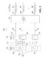
- FIG. 1presents a cochlear stimulation system 10 that includes a sound processor portion 12 and a cochlear stimulation portion 20 .
- the sound processor portion 12includes a microphone 14 and a sound processor 18 .
- the microphone 14can be connected directly to the sound processor 18 .
- the microphone 14can be coupled to the sound processor 18 through an appropriate communication link 16 .
- the cochlear stimulation portion 20includes an implantable cochlear stimulator 22 and an electrode array 24 .
- the electrode array 24is adapted to be inserted within the cochlea of a patient.
- the electrode array 24includes a plurality of electrodes (not shown) that are distributed along the length of the array and are selectively connected to the implantable cochlear stimulator 22 .
- the electrode array 24may be substantially as shown and described in U.S. Pat. Nos. 4,819,647 or 6,129,753, both patents incorporated herein by reference.
- Electronic circuitry within the implantable cochlear stimulator 22allows a specified stimulation current to be applied to selected pairs or groups of the electrodes (not shown) included within the electrode array 24 in accordance with a specified stimulation pattern defined by the sound processor 18 .
- the sound processor 18 and the implantable cochlear stimulator 22are electronically coupled through a suitable communication link 26 .
- the microphone 14 and the sound processor 18comprise an external portion of the cochlear stimulation system 10
- the implantable cochlear stimulator 22 and the electrode array 24comprise an internal, or implanted, portion of the cochlear stimulation system 10 .
- the communication link 26is a transcutaneous (through the skin) link that allows power and control signals to be sent from the sound processor 18 to the implantable cochlear stimulator 22 .
- the implantable cochlear stimulator 22can send information, such as data and status signals, to the sound processor 18 over the communication link 26 .
- the communication link 26can include more than one channel. Additionally, interference can be reduced by transmitting information on a first channel using an amplitude-modulated carrier and transmitting information on a second channel using a frequency-modulated carrier.
- the communication link 26can be realized though use of an antenna coil in the implantable cochlear stimulator 22 and an external antenna coil coupled to the sound processor 18 .
- the external antenna coilcan be positioned so that it is aligned with the implantable cochlear stimulator 22 , allowing the coils to be inductively coupled to each other and thereby permitting power and information, e.g., a stimulation signal, to be transmitted from the sound processor 18 to the implantable cochlear stimulator 22 .
- the sound processor 18 and the implantable cochlear stimulator 22can both be implanted within the patient, and the communication link 26 can be a direct-wired connection or other suitable link as shown in U.S. Pat. No. 6,308,101, incorporated herein by reference.
- the microphone 14senses acoustic signals and converts the sensed acoustic signals to corresponding electrical signals.
- the electrical signalsare sent to the sound processor 18 over an appropriate communication link 16 , such as a circuit or bus.
- the sound processor 18processes the electrical signals in accordance with a sound processing strategy and generates control signals used to control the implantable cochlear stimulator 22 .
- control signalscan specify or define the polarity, magnitude, location (which electrode pair or group is intended to receive the stimulation current), and timing (when the stimulation current is to be applied to the intended electrode pair or group) of the stimulation signal, such as a stimulation current, that is generated by the implantable cochlear stimulator 22 .
- a sound processing strategyinvolves defining a pattern of stimulation waveforms that are applied as controlled electrical currents to the electrodes of an electrode array 24 implanted in a patient. Stimulation strategies can be implemented by modulating the amplitude of the stimulation signal or by modulating the frequency of the stimulation signal.
- the methods and apparatus described hereimplement techniques for clarifying sound as perceived through a cochlear implant. More specifically, the methods and apparatus described here implement techniques for using the outer hair cell model to enhance contrasts between stimulation signals as perceived through a cochlear implant.
- the techniquescan be implemented to include dividing an audio signal into a plurality of input signals, wherein each input signal is associated with a frequency band; generating a plurality of envelope signals, including at least a first and a second envelope signal, by determining an envelope of each of at least two input signals, each input signal being associated with a corresponding frequency band; scaling at least one of the envelope signals in accordance with a scaling factor to generate at least one scaled envelope signal; and combining at least one envelope signal with at least one scaled envelope signal to generate an output signal.
- the techniquesalso can be implemented to include multiplying the first envelope signal by a first weighting factor and multiplying the second envelope signal by a second weighting factor.
- the techniquescan further be implemented to include determining a separation between a first frequency band and a second frequency band, and selecting a scaling factor based on the separation. Additionally, the techniques can be implemented to include scaling a plurality of envelope signals associated with frequency bands that neighbor a first frequency band to generate a plurality of scaled envelope signals, and combining the envelope signal associated with the first frequency band with the plurality of scaled envelope signals to generate an output signal associated with the first frequency band.
- the techniquesalso can be implemented to include rectifying an input signal prior to determining the envelope of the input signal. Further, the techniques can be implemented to include full-wave rectifying the input signal. Additionally, the techniques can be implemented to include setting an average amplitude associated with an input signal to zero at the beginning of a frame and determining the average amplitude associated with the input signal for the frame. The techniques also can be implemented such that the generated output signal comprises an acoustic signal. Further, the techniques can be implemented to include mapping the generated output signal to an electrical signal and applying the electrical signal to one or more electrode pairs of a cochlear implant. Additionally, the techniques can be implemented such that the generated output signal is associated with a first frequency band.
- the techniquesalso can be implemented such that combining further comprises generating an output signal in accordance with a frequency modulated stimulation strategy, such as that described in U.S. patent application Ser. No. 10/917,789, incorporated herein by reference. Further, the techniques can be implemented to include subtracting the at least one scaled envelope signal from the at least one envelope signal. Additionally, the techniques can be implemented such that scaling at least one of the envelope signals reduces the magnitude of the envelope signal. The techniques also can be implemented such that each of the plurality of envelope signals represents an average amplitude of a corresponding input signal. Further, the techniques can be implemented such that scaling in accordance with a scaling factor comprises using a scaling factor which ranges from 0 to 1.
- the techniquescan be implemented to include a plurality of filters configured to divide an audio signal into a plurality of input signals, wherein each input signal is associated with a frequency band; a plurality of envelope detectors configured to generate a plurality of envelope signals, including at least a first and a second envelope signal, by determining an envelope of each of at least two input signals, each input signal being associated with a corresponding frequency band; and circuitry configured to scale at least one of the envelope signals in accordance with a scaling factor to generate at least one scaled envelope signal and to combine at least one envelope signal with at least one scaled envelope signal to generate an output signal.
- the techniquesalso can be implemented to include circuitry configured to multiply the first envelope signal by a first weighting factor and multiply the second envelope signal by a second weighting factor.
- the techniquesalso can be implemented to include circuitry configured to determine a separation between a first frequency band and a second frequency band, and select a scaling factor based on the separation. Additionally, the techniques can be implemented to include circuitry configured to scale a plurality of envelope signals associated with frequency bands that neighbor a first frequency band to generate a plurality of scaled envelope signals and combine the envelope signal associated with the first frequency band with the plurality of scaled envelope signals to generate an output signal associated with the first frequency band.
- the techniquesalso can be implemented to include a rectifier configured to rectify an input signal prior to the envelope detector determining the envelope of the input signal. Further, the techniques can be implemented such that the rectifier comprises a full-wave rectifier. Additionally, the techniques can be implemented such that the envelope detector is configured to set an average amplitude associated with an input signal to zero at the beginning of a frame and determine the average amplitude associated with the input signal for the frame. The techniques can also be implemented such that the generated output signal comprises an acoustic signal.
- the techniquesalso can be implemented to include circuitry configured to map the generated output signal to an electrical signal and apply the electrical signal to one or more electrode pairs of a cochlear implant. Further, the techniques can be implemented such that the generated output signal is associated with a first frequency band. Additionally, the techniques can be implemented to include circuitry configured to generate the output signal in accordance with a frequency modulated stimulation strategy.
- the techniquesalso can be implemented to include circuitry configured to subtract the at least one scaled envelope signal from the at least one envelope signal. Further, the techniques can be implemented such that scaling at least one of the envelope signals reduces the magnitude of the envelope signal. Additionally, the techniques can be implemented such that each of the plurality of envelope detectors is configured to generate an envelope signal representing an average amplitude of a corresponding input signal. Further, the techniques can be implemented such that the circuitry comprises one or more of a programmable logic device, a field programmable gate array, an application-specific integrated circuit, and a general purpose processor executing programmed instructions. The techniques can also be implemented such that the scaling factor ranges from 0 to 1.
- the techniquescan be implemented to include dividing an audio signal into at least a first input signal and a second input signal, wherein each input signal is associated with a frequency band; determining an effect of the second input signal on the first input signal; and subtracting the effect of the second input signal from the first input signal to generate an output signal.
- the techniques described in this specificationcan be implemented to realize one or more of the following advantages.
- the techniquescan be implemented to enhance the contrast between neighboring stimulation signals of a sound processing strategy and thus improve sound clarity and speech recognition, especially under difficult listening conditions.
- the techniquesalso can be implemented to decrease the power consumption of a cochlear implant system implementing a sound processing strategy.
- the techniquescan be implemented to reduce interaction between neighboring electrodes and the resulting influence on corresponding neurons by decreasing the stimulation level on one or more electrodes as a result of the stimulation level present on one or more neighboring electrodes.
- FIG. 1is a block diagram of a cochlear stimulation system.
- FIGS. 2-3show a functional block diagram of a sound processing system.
- FIG. 4presents exemplary frequency maps that can be used in conjunction with a sound processing strategy.
- FIG. 5is a functional block diagram of a lateral suppression network of a sound processing system.
- FIG. 6presents results comparing a Continuous Interleaved Sampler (CIS) strategy used in conjunction with an outer hair cell model and a CIS strategy used without an outer hair cell model.
- CISContinuous Interleaved Sampler
- FIG. 7is a flowchart of a method of stimulating a cochlea.
- FIG. 2presents a functional block diagram of a conventional system arranged to implement a sound processing strategy.
- an audio signal 102is provided as an input to a bank of bandpass filters 104 , which separates the audio signal 102 into individual frequency bands or channels.
- a bank of bandpass filters 104which separates the audio signal 102 into individual frequency bands or channels.
- the audio signal 102is provided to a bank of K bandpass filters, then the audio signal 102 is separated into K individual frequency bands.
- different types and combinations of filterscan be employed to separate the audio signal 102 into individual frequency bands, such as notch filters, high-pass filters, and low-pass filters.
- the bank of bandpass filters 104As the audio signal 102 is provided to the bank of bandpass filters 104 , individual bandpass filters output filtered signals.
- the bank of bandpass filters 104includes a bandpass filter 106 corresponding to a first frequency band, a bandpass filter 108 corresponding to a second frequency band, and a bandpass filter 110 corresponding to a k th frequency band.
- the bandpass filter 106 corresponding to the first frequency bandoutputs a filtered signal 112 associated with the first frequency band
- the bandpass filter 108 corresponding to the second frequency bandoutputs a filtered signal 113 associated with the second frequency band
- the bandpass filter 110 corresponding to the k th frequency bandoutputs a filtered signal 114 associated with the k th frequency band.
- each filtered signalis associated with a frequency band that represents a subset of the audio signal 102 .
- the bank of envelope detectors 116includes an envelope detector 118 corresponding to the first frequency band, an envelope detector 120 corresponding to the second frequency band, and an envelope detector 122 corresponding to the k th frequency band.
- the envelope detectors of the bank of envelope detectors 116receive as input filtered signals output from the corresponding bandpass filters in the bank of bandpass filters 104 .
- the envelope detector 118 corresponding to the first frequency bandreceives as input the filtered signal 112 associated with the first frequency band from the bandpass filter 106 corresponding to the first frequency band.
- Each envelope detector of the bank of envelope detectors 116is configured to determine an envelope associated with a received filtered signal and to output a representative envelope signal.
- the filtered signal 112 associated with the first frequency bandis input to the envelope detector 118 corresponding to the first frequency band, which determines the envelope of the filtered signal 112 and outputs an envelope signal E 1 124 associated with the first frequency band.
- the filtered signal 113 associated with the second frequency bandis input to the envelope detector 120 corresponding to the second frequency band, which determines the envelope of the filtered signal 113 and outputs an envelope signal E 2 134 associated with the second frequency band.
- the filtered signal 114 associated with the k th frequency bandis input to the envelope detector 122 corresponding to the k th frequency band, which determines the envelope of the filtered signal 114 and outputs an envelope signal E k 144 associated with the k th frequency band.
- the envelope signals output from the bank of envelope detectors 116are converted to electrical signals using acoustic-to-electrical mappings. Each of the resulting electrical signals is then applied to electrodes of a cochlear implant to provide a stimulation signal.
- the envelope signal E 1 124 output from the envelope detector 118 corresponding to the first frequency bandis converted from an acoustic signal to an electrical signal using the acoustic-to-electrical mapping 132 associated with the first frequency band.
- the envelope signals E 2 134 and E k 144are converted to electrical signals using the acoustic-to-electrical mappings 142 and 152 associated with the second frequency band and the k th frequency band respectively.
- a signal corresponding to a particular frequency bandis either provided to an electrode array as a stimulation signal at full strength or the signal is completely suppressed.
- the N of M algorithmsimply determines the amplitude of the signals on each of M frequency bands and selects the N signals with the highest amplitudes to provide as stimulation signals. The remaining M-N signals are completely suppressed.
- sound processing strategies used to generate stimulation signalsoften incorporate the assumption that each frequency band, or channel, is represented independently in the cochlea. This assumption can result in poor sound quality and decreased comprehension of speech under difficult listening conditions, such as listening in a noisy environment.
- One factor believed to contribute to the poor performanceis the interaction that occurs between frequency bands in cochlear implant subjects. Such frequency band interaction can smear or distort peaks in the stimulation signal that are essential to the identification of sounds.
- FIG. 3presents a functional block diagram of a system arranged to implement a sound processing strategy.
- Such sound processing strategycan be implemented using any combination of circuitry and programmed instructions, including one or more of a programmable logic device, a field-programmable gate array, an application-specific integrated circuit, and a general purpose processor executing programmed instructions.
- an audio signal 102is also provided to a bank of bandpass filters 104 , which separates the audio signal 102 into a plurality of frequency bands or channels.
- the bank of bandpass filters 104can be configured to separate the audio signal 102 into frequency bands that correspond to frequencies defined in a frequency map associated with a specific sound processing strategy.
- FIG. 4presents an example of a frequency map associated with the Simultaneous Analog Stimulation (SAS) strategy 410 and a frequency map associated with the Continuous Interleaved Sampler (CIS) strategy 420 .
- SASSimultaneous Analog Stimulation
- CISContinuous Interleaved Sampler
- Other sound processing strategiessuch as the Frequency Modulated Stimulation (FMS) strategy, can be implemented using either of the frequency maps presented in FIG. 4 , or by using alternative frequency maps.
- FMSFrequency Modulated Stimulation
- the audio signal 102can undergo other processing before being provided as input to the bank of bandpass filters 104 .
- the audio signal 102may originate as acoustic information sensed by a microphone, which is then converted into an electrical signal representing an audio signal.
- the electrical signalcan further be converted to a digital signal in an analog-to-digital converter, and then subjected to automatic gain control (AGC) processing using an AGC algorithm.
- AGCautomatic gain control
- the AGC algorithmserves to compress the dynamic range of the audio signals to provide a more consistent level of stimulus to the electrodes and to equalize the level between sound sources that are removed from the listener by differing distances.
- the bank of envelope detectors 116includes an envelope detector 118 corresponding to the first frequency band, an envelope detector 120 corresponding to the second frequency band, and an envelope detector 122 corresponding to the k th frequency band.
- the envelope detectors of the bank of envelope detectors 116receive as input filtered signals output from the corresponding bandpass filters in the bank of bandpass filters.
- the envelope detector 118 corresponding to the first frequency bandreceives as input the filtered signal 112 associated with the first frequency band from the bandpass filter 106 corresponding to the first frequency band.
- Each of the envelope detectors of the bank of envelope detectors 116can include a rectifier, such as a half-wave rectifier or a full-wave rectifier, that rectifies the filtered signal output from the corresponding bandpass filter of the bank of bandpass filters 104 before the envelope of the filtered signal is determined.
- a rectifiersuch as a half-wave rectifier or a full-wave rectifier
- the envelope detectors included in the bank of envelope detectors 116can comprise integrators that determine an average amplitude of a signal for a given interval. For example, upon receiving the filtered signal 112 associated with the first frequency band, the envelope detector 118 corresponding to the first frequency band determines an envelope of the filtered signal 112 for an interval, such as a frame. At the end of the interval, the envelope detector 118 corresponding to the first frequency band outputs the envelope signal E 1 124 , which represents the average amplitude of the filtered signal 112 associated with the first frequency band for that interval.
- Each envelope detector of the bank of envelope detectors 116also can be configured to set the average amplitude value of a received filtered signal to an initial state prior to or at the start of a new interval.
- the bank of envelope detectorsoutputs envelope signals representing acoustic signal values.
- the envelope signalsare not converted to electrical signals using an acoustic-to-electrical mapping. Instead, the envelope signals are transferred to a lateral suppression network 154 , which accounts for the interaction between envelope signals of neighboring frequency bands through the use of a lateral suppression model, such as the outer hair cell model, and outputs suppressed signals.
- a lateral suppression modelsuch as the outer hair cell model, can be used in conjunction with either a frequency modulated sound processing strategy, such as FMS, or an amplitude modulated stimulation strategy, such as CIS.
- the lateral suppression network 154is discussed in greater detail with reference to FIG. 5 .
- Lateral suppressionis the term used to describe the psychophysical effect by which the loudness perceived from one tone is diminished to some extent by the presence of a neighboring tone. The suppressive effect is particularly evident when a loud tone closely neighbors a quieter tone. Thus, lateral suppression operates to enhance the contrast between tones. However, the lateral suppression algorithm must be implemented such that it does not generate abnormal results. If a flat spectrum is input to the lateral suppression network 154 , a flat spectrum should also be output from the lateral suppression network 154 . Further, the lateral suppression network must account for the frequency bands representing the highest and lowest frequencies of the audio signal 102 , the edge frequency bands. In the system 300 , for example, the first frequency band and the k th frequency band are the edge frequency bands.
- each edge frequency bandwould be subjected to less suppression without additional compensation. Therefore, the lateral suppression network 154 must compensate by adjusting one or more factors, such as the weighting factor u associated with the edge frequency band or one or more of the scaling factors w employed by the lateral suppression processor associated with the edge frequency band.
- the suppressed signals output from the lateral suppression network 154are converted to electrical signals using the acoustic-to-electrical mapping associated with the corresponding frequency bands and provided as stimulation signals to one or more electrode pairs of a cochlear implant.
- the envelope signals E 1 124 , E 2 134 , and E k 144 output from the bank of envelope detectors 116are input into the lateral suppression network 154 .
- the lateral suppression network 154then suppresses one or more of the envelope signals E 1 124 , E 2 134 , and E k 144 in accordance with envelope signals associated with neighboring frequency bands, including the envelope signals E 1 124 , E 2 134 , and E k 144 .
- the lateral suppression network 154then outputs the corresponding suppressed signals S 1 130 , S 2 140 , and S k 150 respectively.
- the suppressed signal S 1 130 associated with the first frequency bandis then converted into an electrical signal using the acoustic-to-electrical mapping 132 corresponding to the first frequency band.
- the suppressed signal S 2 140 associated with the second frequency bandis then converted into an electrical signal using the acoustic-to-electrical mapping 142 corresponding to the second frequency band.
- the suppressed signal S k 150 associated with the k th frequency bandis then converted into an electrical signal using the acoustic-to-electrical mapping 152 corresponding to the k th frequency band.
- FIG. 5presents a functional block diagram detailing an implementation of a lateral suppression network 154 as it relates to the system 300 of FIG. 3 .
- the envelope signals E 1 124 , E 2 134 , and E k 144are provided as inputs to the lateral suppression network 154 .
- each envelope signalcan be combined with one or more scaled envelope signals to account for the influence that envelope signals associated with neighboring frequency bands have on a particular envelope signal.
- One or more of the envelope signals output from the bank of envelope detectors 116can be weighted by a factor u i upon being provided to the lateral suppression network 154 , where i represents the frequency band with which the envelope signal is associated.
- irepresents the frequency band with which the envelope signal is associated.
- an envelope signal that is determined to be of greater importance than the envelope signals associated with neighboring frequency bandscan be emphasized, such as an envelope signal representing an amplitude that exceeds a particular threshold value.
- an envelope signal determined to be of lesser importancecan be deemphasized, such as an envelope signal representing an amplitude that falls below a particular threshold value.
- each of the envelope signals provided to the lateral suppression network 154can be weighted, and the weight associated with envelope signals that should not be emphasized or deemphasized can be set to 1.
- the envelope signals E 1 124 , E 2 134 , and E k 144 output from the bank of envelope detectors 116are provided as inputs to the lateral suppression network 154 .
- the lateral suppression processor 128 corresponding to the first frequency bandmultiplies the envelope signal E 1 124 by a weighting factor u i 126 associated with the first frequency band.
- the lateral suppression processor 138 corresponding to the second frequency bandmultiplies the envelope signal E 2 134 by a weighting factor u 2 136 associated with the second frequency band.
- the lateral suppression processor 148 corresponding to the k th frequency bandmultiplies the envelope signal E k 144 by a weighting factor u k 146 associated with the k th frequency band.
- the scaling factor applied to an envelope signal to generate a scaled envelope signalis selected as a function of the separation of between the neighboring frequency bands. Therefore, a scaling factor w ij is chosen, where i represents the frequency band associated with the envelope signal being suppressed and j represents the frequency band associated with the envelope signal that is producing the suppressive effect. With each increase in the frequency band separation, the scaling factor w ij will further decrease the magnitude of the envelope signal being scaled. Additionally, as scaled envelope signals suppress an envelope signal, the scaling factor represents a negative value.
- a laterally suppressed signal S iis generated by combining an envelope signal associated with a particular frequency band E i with one or more scaled envelope signals w ij E j associated with neighboring frequency bands.
- the envelope signal being suppressedalso can be weighted using a weighting factor u i .
- the combining operationcan be expressed mathematically as shown in Equation 1.
- the envelope signal E 1 124 associated with the first frequency bandis provided to a corresponding lateral suppression processor 128 .
- the lateral suppression processor 128then multiplies the envelope signal E 1 124 by the weighting factor u 1 126 .
- the lateral suppression processor 128also receives as input the scaled envelope signal w 12 E 2 156 , which represents the interaction of the envelope signal E 2 134 associated with the second frequency band with the envelope signal E 1 124 associated with the first frequency band.
- the lateral suppression processor 128receives as input the scaled envelope signal w 1k E k 158 , which represents the interaction of the envelope signal E k 144 associated with the k th frequency band with the envelope signal E 1 124 associated with the first frequency band.
- the lateral suppression processor 128can also receive as inputs the scaled envelope signals associated with any or all of the remaining third through K ⁇ 1 th frequency bands.
- the lateral suppression processor 128combines the envelope signal E 1 124 , weighted by u 1 126 , with at least the scaled envelope signals w 12 E 2 156 and w 1k E k 158 , and outputs a laterally suppressed signal S 1 130 associated with the first frequency band.
- the laterally suppressed signal S 1 130can then be converted to an electrical stimulation signal using the acoustic-to-electrical mapping 132 corresponding to the first frequency band.
- a similar lateral suppression operationcan be carried out for any or all of the envelope signals associated with the remaining frequency bands.
- the lateral suppression processor 138receives the envelope signal E 2 134 associated with the second frequency band.
- the lateral suppression processor 138then multiplies the envelope signal E 2 134 by the weighting factor u 2 136 .
- the lateral suppression processor 138also receives as inputs the scaled envelope signals w 21 E 1 160 and w 2k E k 162 , which are associated with the first and k th frequency bands respectively.
- the lateral suppression processor 138can receive as inputs the scaled envelope signals associated with any or all of the remaining frequency bands.
- the lateral suppression processor 138combines the envelope signal E 2 134 , weighted by u 2 136 , with the scaled envelope signals w 21 E 1 160 and w 2k E k 162 , and outputs a laterally suppressed signal S 2 140 associated with the second frequency band.
- the laterally suppressed signal S 2 140is then converted to an electrical stimulation signal using the acoustic-to-electrical mapping 142 associated with the second frequency band.
- each lateral suppression processor of the lateral suppression network 154can be configured to receive as inputs the scaled envelope signals associated with each of the neighboring frequency bands. Therefore, each of the envelope signals can be suppressed by scaled envelope signals associated with each of the neighboring frequency bands. If an envelope signal E b should not be used to suppress an envelope signal E a , the scaling factor w ab can be set to 0.
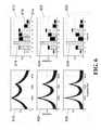
- FIG. 6presents a graphical comparison of the stimulation signals generated in response to varying input signals using the CIS strategy employed in conjunction with the outer hair cell model and the CIS strategy employed without the outer hair cell model.
- the spectrum of the stimulation signals generated in response to the first input signal 610 using CIS processing in conjunction with the outer hair cell modelare indicated in the first bar graph 612 by light colored bars, such as the light bar 614 associated with channel 7 .
- the spectrum of the stimulation signals generated in response to the first input signal 610 using CIS processing without the outer hair cell modelare indicated in the first bar graph 612 using dark colored bars, such as the dark bar 616 associated with channel 7 .
- the dark colored barsare depicted behind the light colored bars.
- Each of the dark colored bars and each of the light colored barsrepresents an amplitude of a stimulation signal corresponding to a particular channel. Where a dark colored bar is visible, such as the dark colored bar 616 associated with channel 7 , the amplitude of the stimulation signal generated using CIS processing without the outer hair cell model exceeds the amplitude of the stimulation signal generated using CIS processing in conjunction with the outer hair cell model.
- CIS processing used in conjunction with the outer hair cell modelproduces stimulation signals characterized by greater channel-to-channel amplitude differences than the stimulation signals produced using CIS processing without the outer hair cell model. This is especially true for channels adjacent to signal peaks, such as the stimulation signal represented by the light bar 618 of channel 3 . Therefore, CIS processing performed in conjunction with the outer hair cell model provides enhanced stimulation signal contrast over CIS processing performed without the outer hair cell model.
- the second bar graph 622 corresponding to the second input signal 620indicates that as the peaks in the spectrum of the input signal become more pronounced, CIS processing in conjunction with the outer hair cell model produces stimulation signals characterized by even greater channel-to-channel amplitude differences than the stimulation signals produced using CIS processing without the outer hair cell model. As discussed above, this is especially true for channels adjacent to peaks in the spectrum, such as the stimulation signal represented by the light bar 624 of channel 3 .
- the third bar graph 632 corresponding to the third input signal 630provides further indication that, as the peaks of the spectrum of the input signal become very pronounced, CIS processing in conjunction with the outer hair cell model produces stimulation signals characterized by even greater channel-to-channel amplitude differences than the stimulation signals produced using CIS processing without the outer hair cell model. Again, this is especially true for channels adjacent to large peaks in the spectrum, such as the stimulation signal 634 of channel 3 .
- FIG. 7describes a method of stimulating a cochlea using a lateral suppression strategy, such as the outer hair cell model.
- a first step 710as described above, an audio signal 102 is divided into a plurality of input signals using a bank of bandpass filters 104 . Each of the input signals generated from the audio signal 102 is associated with a frequency band.
- a plurality of envelope signalsincluding at least a first and second envelope signal, are generated by a bank of envelope detectors 106 .
- the individual envelope detectors included in the bank of envelope detectors 106each determine an envelope of an input signal associated with a corresponding frequency band.
- the third step 730is to scale at least one envelope signal in accordance with a scaling factor to generate a scaled envelope signal. This step generates signals for use in the lateral suppression network 154 .
- a fourth step 740at least one envelope signal is combined with at least one scaled envelope signal to generate an output signal.
Landscapes
- Health & Medical Sciences (AREA)
- Engineering & Computer Science (AREA)
- Physics & Mathematics (AREA)
- Otolaryngology (AREA)
- Acoustics & Sound (AREA)
- Signal Processing (AREA)
- Audiology, Speech & Language Pathology (AREA)
- Radiology & Medical Imaging (AREA)
- Quality & Reliability (AREA)
- Multimedia (AREA)
- Computational Linguistics (AREA)
- Biomedical Technology (AREA)
- Nuclear Medicine, Radiotherapy & Molecular Imaging (AREA)
- Human Computer Interaction (AREA)
- Life Sciences & Earth Sciences (AREA)
- Animal Behavior & Ethology (AREA)
- General Health & Medical Sciences (AREA)
- Public Health (AREA)
- Veterinary Medicine (AREA)
- Prostheses (AREA)
Abstract
Description
Claims (9)
Priority Applications (1)
| Application Number | Priority Date | Filing Date | Title |
|---|---|---|---|
| US12/728,722US8121698B2 (en) | 2004-12-03 | 2010-03-22 | Outer hair cell stimulation model for the use by an intra-cochlear implant |
Applications Claiming Priority (3)
| Application Number | Priority Date | Filing Date | Title |
|---|---|---|---|
| US11/003,155US7242985B1 (en) | 2004-12-03 | 2004-12-03 | Outer hair cell stimulation model for the use by an intra—cochlear implant |
| US76539507A | 2007-06-19 | 2007-06-19 | |
| US12/728,722US8121698B2 (en) | 2004-12-03 | 2010-03-22 | Outer hair cell stimulation model for the use by an intra-cochlear implant |
Related Parent Applications (1)
| Application Number | Title | Priority Date | Filing Date |
|---|---|---|---|
| US76539507AContinuation | 2004-12-03 | 2007-06-19 |
Publications (2)
| Publication Number | Publication Date |
|---|---|
| US20100179616A1 US20100179616A1 (en) | 2010-07-15 |
| US8121698B2true US8121698B2 (en) | 2012-02-21 |
Family
ID=38227107
Family Applications (2)
| Application Number | Title | Priority Date | Filing Date |
|---|---|---|---|
| US11/003,155Expired - LifetimeUS7242985B1 (en) | 2004-12-03 | 2004-12-03 | Outer hair cell stimulation model for the use by an intra—cochlear implant |
| US12/728,722Expired - Fee RelatedUS8121698B2 (en) | 2004-12-03 | 2010-03-22 | Outer hair cell stimulation model for the use by an intra-cochlear implant |
Family Applications Before (1)
| Application Number | Title | Priority Date | Filing Date |
|---|---|---|---|
| US11/003,155Expired - LifetimeUS7242985B1 (en) | 2004-12-03 | 2004-12-03 | Outer hair cell stimulation model for the use by an intra—cochlear implant |
Country Status (1)
| Country | Link |
|---|---|
| US (2) | US7242985B1 (en) |
Cited By (1)
| Publication number | Priority date | Publication date | Assignee | Title |
|---|---|---|---|---|
| US20120197374A1 (en)* | 2011-01-27 | 2012-08-02 | Med-El Elektromedizinische Geraete Gmbh | Combined Stimulation with Controlled Light Distribution for Electro-Optical Cochlear Implants |
Families Citing this family (32)
| Publication number | Priority date | Publication date | Assignee | Title |
|---|---|---|---|---|
| US7203548B2 (en) | 2002-06-20 | 2007-04-10 | Advanced Bionics Corporation | Cavernous nerve stimulation via unidirectional propagation of action potentials |
| US20040015205A1 (en) | 2002-06-20 | 2004-01-22 | Whitehurst Todd K. | Implantable microstimulators with programmable multielectrode configuration and uses thereof |
| US7860570B2 (en) | 2002-06-20 | 2010-12-28 | Boston Scientific Neuromodulation Corporation | Implantable microstimulators and methods for unidirectional propagation of action potentials |
| US7292890B2 (en) | 2002-06-20 | 2007-11-06 | Advanced Bionics Corporation | Vagus nerve stimulation via unidirectional propagation of action potentials |
| US7702396B2 (en)* | 2003-11-21 | 2010-04-20 | Advanced Bionics, Llc | Optimizing pitch allocation in a cochlear implant |
| US7522961B2 (en) | 2004-11-17 | 2009-04-21 | Advanced Bionics, Llc | Inner hair cell stimulation model for the use by an intra-cochlear implant |
| US7599500B1 (en) | 2004-12-09 | 2009-10-06 | Advanced Bionics, Llc | Processing signals representative of sound based on the identity of an input element |
| US7450994B1 (en)* | 2004-12-16 | 2008-11-11 | Advanced Bionics, Llc | Estimating flap thickness for cochlear implants |
| CA2594963A1 (en)* | 2005-01-24 | 2006-07-27 | Neurosystec Corporation | Apparatus and method for delivering therapeutic and/or other agents to the inner ear and to other tissues |
| US20100292759A1 (en)* | 2005-03-24 | 2010-11-18 | Hahn Tae W | Magnetic field sensor for magnetically-coupled medical implant devices |
| US7801600B1 (en) | 2005-05-26 | 2010-09-21 | Boston Scientific Neuromodulation Corporation | Controlling charge flow in the electrical stimulation of tissue |
| US20090222064A1 (en)* | 2005-07-08 | 2009-09-03 | Advanced Bionics, Llc | Autonomous Autoprogram Cochlear Implant |
| US20100331913A1 (en)* | 2005-10-28 | 2010-12-30 | Mann Alfred E | Hybrid multi-function electrode array |
| US8027733B1 (en) | 2005-10-28 | 2011-09-27 | Advanced Bionics, Llc | Optimizing pitch allocation in a cochlear stimulation system |
| US7729775B1 (en) | 2006-03-21 | 2010-06-01 | Advanced Bionics, Llc | Spectral contrast enhancement in a cochlear implant speech processor |
| US8267905B2 (en)* | 2006-05-01 | 2012-09-18 | Neurosystec Corporation | Apparatus and method for delivery of therapeutic and other types of agents |
| US8818517B2 (en) | 2006-05-05 | 2014-08-26 | Advanced Bionics Ag | Information processing and storage in a cochlear stimulation system |
| US7803148B2 (en) | 2006-06-09 | 2010-09-28 | Neurosystec Corporation | Flow-induced delivery from a drug mass |
| US7995771B1 (en) | 2006-09-25 | 2011-08-09 | Advanced Bionics, Llc | Beamforming microphone system |
| US7864968B2 (en)* | 2006-09-25 | 2011-01-04 | Advanced Bionics, Llc | Auditory front end customization |
| US7979135B2 (en)* | 2007-07-03 | 2011-07-12 | Med-El Elektromedizinische Geraete Gmbh | Cochlear implant pitch intensity |
| US8600516B2 (en) | 2007-07-17 | 2013-12-03 | Advanced Bionics Ag | Spectral contrast enhancement in a cochlear implant speech processor |
| US8412343B2 (en)* | 2009-01-28 | 2013-04-02 | Med-El Elektromedizinische Geraete Gmbh | Channel specific gain control including lateral suppression |
| US8688222B2 (en)* | 2009-02-05 | 2014-04-01 | Cochlear Limited | Stimulus timing for a stimulating medical device |
| CN101645267B (en)* | 2009-04-03 | 2012-02-01 | 中国科学院声学研究所 | A Speech Processing Method Applied to Cochlear Electronics |
| US9242094B2 (en) | 2010-01-12 | 2016-01-26 | The Johns Hopkins University | Implantable vestibular prosthesis |
| CA2786717C (en) | 2010-01-12 | 2018-03-20 | The Johns Hopkins University | Implantable vestibular prosthesis |
| US9656076B2 (en) | 2011-04-07 | 2017-05-23 | Nuvectra Corporation | Arbitrary waveform generator and neural stimulation application with scalable waveform feature and charge balancing |
| US8996117B2 (en)* | 2011-04-07 | 2015-03-31 | Greatbatch, Ltd. | Arbitrary waveform generator and neural stimulation application with scalable waveform feature |
| US9403005B2 (en) | 2011-05-02 | 2016-08-02 | Advanced Bionics Ag | Systems and methods for optimizing a compliance voltage of an auditory prosthesis |
| US9446236B2 (en)* | 2011-05-02 | 2016-09-20 | Advanced Bionics Ag | Systems and methods for optimizing a compliance voltage of an auditory prosthesis |
| US9623242B2 (en) | 2015-07-10 | 2017-04-18 | Northwestern University | Methods of frequency-modulated phase coding (FMPC) for cochlear implants and cochlear implants applying same |
Citations (71)
| Publication number | Priority date | Publication date | Assignee | Title |
|---|---|---|---|---|
| US4532930A (en) | 1983-04-11 | 1985-08-06 | Commonwealth Of Australia, Dept. Of Science & Technology | Cochlear implant system for an auditory prosthesis |
| US4612934A (en) | 1981-06-30 | 1986-09-23 | Borkan William N | Non-invasive multiprogrammable tissue stimulator |
| US4793353A (en) | 1981-06-30 | 1988-12-27 | Borkan William N | Non-invasive multiprogrammable tissue stimulator and method |
| US4819647A (en) | 1984-05-03 | 1989-04-11 | The Regents Of The University Of California | Intracochlear electrode array |
| US4905285A (en) | 1987-04-03 | 1990-02-27 | American Telephone And Telegraph Company, At&T Bell Laboratories | Analysis arrangement based on a model of human neural responses |
| US5749912A (en) | 1994-10-24 | 1998-05-12 | House Ear Institute | Low-cost, four-channel cochlear implant |
| US5991663A (en) | 1995-10-17 | 1999-11-23 | The University Of Melbourne | Multiple pulse stimulation |
| US6064913A (en) | 1997-04-16 | 2000-05-16 | The University Of Melbourne | Multiple pulse stimulation |
| US6078838A (en) | 1998-02-13 | 2000-06-20 | University Of Iowa Research Foundation | Pseudospontaneous neural stimulation system and method |
| US6129753A (en) | 1998-03-27 | 2000-10-10 | Advanced Bionics Corporation | Cochlear electrode array with electrode contacts on medial side |
| US6154678A (en) | 1999-03-19 | 2000-11-28 | Advanced Neuromodulation Systems, Inc. | Stimulation lead connector |
| US6198971B1 (en) | 1999-04-08 | 2001-03-06 | Implex Aktiengesellschaft Hearing Technology | Implantable system for rehabilitation of a hearing disorder |
| US6216045B1 (en) | 1999-04-26 | 2001-04-10 | Advanced Neuromodulation Systems, Inc. | Implantable lead and method of manufacture |
| US6219580B1 (en) | 1995-04-26 | 2001-04-17 | Advanced Bionics Corporation | Multichannel cochlear prosthesis with flexible control of stimulus waveforms |
| US6289247B1 (en)* | 1998-06-02 | 2001-09-11 | Advanced Bionics Corporation | Strategy selector for multichannel cochlear prosthesis |
| US6308101B1 (en) | 1998-07-31 | 2001-10-23 | Advanced Bionics Corporation | Fully implantable cochlear implant system |
| US20030114905A1 (en) | 1999-10-01 | 2003-06-19 | Kuzma Janusz A. | Implantable microdevice with extended lead and remote electrode |
| US6600955B1 (en) | 1999-07-21 | 2003-07-29 | Med-El Elektromedizinishe Geraete Gmbh | Multichannel cochlear implant with neural response telemetry |
| US20040015205A1 (en) | 2002-06-20 | 2004-01-22 | Whitehurst Todd K. | Implantable microstimulators with programmable multielectrode configuration and uses thereof |
| US20040015204A1 (en) | 2002-06-20 | 2004-01-22 | Whitehurst Todd K. | Implantable microstimulators and methods for unidirectional propagation of action potentials |
| US6700982B1 (en) | 1998-06-08 | 2004-03-02 | Cochlear Limited | Hearing instrument with onset emphasis |
| US6728578B1 (en) | 2000-06-01 | 2004-04-27 | Advanced Bionics Corporation | Envelope-based amplitude mapping for cochlear implant stimulus |
| US20040082985A1 (en) | 2000-03-31 | 2004-04-29 | Faltys Michael A. | High contact count, sub-miniature, fully implantable cochlear prosthesis |
| US20040082980A1 (en) | 2000-10-19 | 2004-04-29 | Jaouhar Mouine | Programmable neurostimulator |
| WO2004043537A1 (en) | 2002-11-13 | 2004-05-27 | Advanced Bionics Corporation | Method and system to convey the within-channel fine structure with a cochlear implant |
| US6745155B1 (en) | 1999-11-05 | 2004-06-01 | Huq Speech Technologies B.V. | Methods and apparatuses for signal analysis |
| US6775389B2 (en) | 2001-08-10 | 2004-08-10 | Advanced Bionics Corporation | Ear auxiliary microphone for behind the ear hearing prosthetic |
| US6778858B1 (en) | 1999-09-16 | 2004-08-17 | Advanced Bionics N.V. | Cochlear implant |
| US20040230254A1 (en) | 1999-05-14 | 2004-11-18 | Harrison William Vanbrooks | Hybrid implantable cochlear stimulator hearing aid system |
| US20050137651A1 (en) | 2003-11-21 | 2005-06-23 | Litvak Leonid M. | Optimizing pitch allocation in a cochlear implant |
| US6915166B1 (en) | 1999-08-27 | 2005-07-05 | Cochlear Limited | Optimizing cochlear implant electrode selection |
| US20050240229A1 (en) | 2001-04-26 | 2005-10-27 | Whitehurst Tood K | Methods and systems for stimulation as a therapy for erectile dysfunction |
| US20050267555A1 (en) | 2004-05-28 | 2005-12-01 | Marnfeldt Goran N | Engagement tool for implantable medical devices |
| US20060100672A1 (en) | 2004-11-05 | 2006-05-11 | Litvak Leonid M | Method and system of matching information from cochlear implants in two ears |
| US20060106446A1 (en) | 2004-11-17 | 2006-05-18 | Fridman Gene Y | Inner hair cell stimulation model for the use by an intra-cochlear implant |
| US20060161204A1 (en) | 2005-01-20 | 2006-07-20 | Advanced Bionics Corporation | Implantable microstimulator with plastic housing and methods of manufacture and use |
| US7083332B2 (en) | 2001-01-09 | 2006-08-01 | Takahiko Mukouda | Connector component for multi-core optical fiber, ferrule, and method for manufacturing the same |
| US20060184204A1 (en) | 2005-02-11 | 2006-08-17 | Advanced Bionics Corporation | Implantable microstimulator having a separate battery unit and methods of use thereof |
| US20060195143A1 (en) | 2005-02-25 | 2006-08-31 | Mcclure Kelly H | Multiple-pronged implantable stimulator and methods of making and using such a stimulator |
| US20060229688A1 (en) | 2005-04-08 | 2006-10-12 | Mcclure Kelly H | Controlling stimulation parameters of implanted tissue stimulators |
| US7162415B2 (en) | 2001-11-06 | 2007-01-09 | The Regents Of The University Of California | Ultra-narrow bandwidth voice coding |
| US20070021800A1 (en) | 2002-06-20 | 2007-01-25 | Advanced Bionics Corporation, A California Corporation | Cavernous nerve stimulation via unidirectional propagation of action potentials |
| US7171272B2 (en) | 2000-08-21 | 2007-01-30 | University Of Melbourne | Sound-processing strategy for cochlear implants |
| US20070049988A1 (en) | 2005-03-14 | 2007-03-01 | Rafael Carbunaru | Optimal electrode contact polarity configurations for implantable stimulation systems |
| US20070055308A1 (en) | 2005-09-06 | 2007-03-08 | Haller Matthew I | Ultracapacitor powered implantable pulse generator with dedicated power supply |
| US20070066997A1 (en) | 2005-09-21 | 2007-03-22 | He Tom X | Methods and systems for placing an implanted stimulator for stimulating tissue |
| US20070100395A1 (en) | 2002-09-04 | 2007-05-03 | Ibrahim Ibrahim H | Method and apparatus for measurement of transmitter/receiver separation |
| US7225027B2 (en) | 2001-08-27 | 2007-05-29 | Regents Of The University Of California | Cochlear implants and apparatus/methods for improving audio signals by use of frequency-amplitude-modulation-encoding (FAME) strategies |
| US20070123938A1 (en) | 2005-11-30 | 2007-05-31 | Haller Matthew I | Magnetically coupled microstimulators |
| US20070219595A1 (en) | 2006-03-14 | 2007-09-20 | Advanced Bionics Corporation | Stimulator system with electrode array and the method of making the same |
| US7277760B1 (en) | 2004-11-05 | 2007-10-02 | Advanced Bionics Corporation | Encoding fine time structure in presence of substantial interaction across an electrode array |
| US20070239227A1 (en) | 2003-08-15 | 2007-10-11 | Fridman Gene Y | Frequency modulated stimulation strategy for cochlear implant system |
| US7292891B2 (en) | 2001-08-20 | 2007-11-06 | Advanced Bionics Corporation | BioNet for bilateral cochlear implant systems |
| US7292892B2 (en) | 2003-11-21 | 2007-11-06 | Advanced Bionics Corporation | Methods and systems for fitting a cochlear implant to a patient |
| US20070260292A1 (en) | 2006-05-05 | 2007-11-08 | Faltys Michael A | Information processing and storage in a cochlear stimulation system |
| US7308303B2 (en) | 2001-11-01 | 2007-12-11 | Advanced Bionics Corporation | Thrombolysis and chronic anticoagulation therapy |
| US7310558B2 (en) | 2001-05-24 | 2007-12-18 | Hearworks Pty, Limited | Peak-derived timing stimulation strategy for a multi-channel cochlear implant |
| US20070293785A1 (en) | 2004-11-05 | 2007-12-20 | Litvak Leonid M | Encoding Fine Time Structure in Presence of Substantial Interaction Across An Electrode Array |
| US20080065183A1 (en) | 2002-06-20 | 2008-03-13 | Advanced Bionics Corporation | Vagus nerve stimulation via unidirectional propagation of action potentials |
| US7349741B2 (en) | 2002-10-11 | 2008-03-25 | Advanced Bionics, Llc | Cochlear implant sound processor with permanently integrated replenishable power source |
| US7347746B1 (en) | 2006-10-27 | 2008-03-25 | Boston Scientific Neuromodulation Corporation | Receptacle connector assembly |
| US20080085023A1 (en) | 2006-09-25 | 2008-04-10 | Abhijit Kulkarni | Auditory Front End Customization |
| US7376466B2 (en) | 2005-01-26 | 2008-05-20 | Boston Scientific Neuromodulation Corporation | Casings for implantable stimulators and methods of making the same |
| US20080132961A1 (en) | 2006-11-30 | 2008-06-05 | Advanced Bionics Corporation | Implant tool for use with a microstimulator |
| US7426445B1 (en) | 2005-05-16 | 2008-09-16 | Boston Scientific Neuromodulation Corporation | Measuring temperature change in an electronic biomedical implant |
| US7444180B2 (en) | 2005-05-25 | 2008-10-28 | Boston Scientific Neuromodulation Corporation | Implantable microstimulator with dissecting tip and/or retrieving anchor and methods of manufacture and use |
| US7445528B1 (en) | 2006-09-29 | 2008-11-04 | Boston Scientific Neuromodulation Corporation | Connector assemblies |
| US7450994B1 (en) | 2004-12-16 | 2008-11-11 | Advanced Bionics, Llc | Estimating flap thickness for cochlear implants |
| US7599500B1 (en) | 2004-12-09 | 2009-10-06 | Advanced Bionics, Llc | Processing signals representative of sound based on the identity of an input element |
| US7627383B2 (en) | 2005-03-15 | 2009-12-01 | Boston Scientific Neuromodulation Corporation | Implantable stimulator |
| US7660631B2 (en) | 2001-04-26 | 2010-02-09 | Boston Scientific Neuromodulation Corporation | Methods and systems for electrical and/or drug stimulation as a therapy for erectile dysfunction |
Family Cites Families (3)
| Publication number | Priority date | Publication date | Assignee | Title |
|---|---|---|---|---|
| US4819648A (en)* | 1985-10-28 | 1989-04-11 | The Johns Hopkins University | Non-invasive electromagnetic technique for monitoring time-trends of physiological changes at a particular location in the brain |
| AUPQ820500A0 (en) | 2000-06-19 | 2000-07-13 | Cochlear Limited | Travelling wave sound processor |
| AU2003300040A1 (en)* | 2002-12-31 | 2004-07-29 | Massachusetts Institute Of Technology | Multi-layer integrated semiconductor structure having an electrical shielding portion |
- 2004
- 2004-12-03USUS11/003,155patent/US7242985B1/ennot_activeExpired - Lifetime
- 2010
- 2010-03-22USUS12/728,722patent/US8121698B2/ennot_activeExpired - Fee Related
Patent Citations (82)
| Publication number | Priority date | Publication date | Assignee | Title |
|---|---|---|---|---|
| US4612934A (en) | 1981-06-30 | 1986-09-23 | Borkan William N | Non-invasive multiprogrammable tissue stimulator |
| US4793353A (en) | 1981-06-30 | 1988-12-27 | Borkan William N | Non-invasive multiprogrammable tissue stimulator and method |
| US4532930A (en) | 1983-04-11 | 1985-08-06 | Commonwealth Of Australia, Dept. Of Science & Technology | Cochlear implant system for an auditory prosthesis |
| US4819647A (en) | 1984-05-03 | 1989-04-11 | The Regents Of The University Of California | Intracochlear electrode array |
| US4905285A (en) | 1987-04-03 | 1990-02-27 | American Telephone And Telegraph Company, At&T Bell Laboratories | Analysis arrangement based on a model of human neural responses |
| US5749912A (en) | 1994-10-24 | 1998-05-12 | House Ear Institute | Low-cost, four-channel cochlear implant |
| US6219580B1 (en) | 1995-04-26 | 2001-04-17 | Advanced Bionics Corporation | Multichannel cochlear prosthesis with flexible control of stimulus waveforms |
| US5991663A (en) | 1995-10-17 | 1999-11-23 | The University Of Melbourne | Multiple pulse stimulation |
| US6064913A (en) | 1997-04-16 | 2000-05-16 | The University Of Melbourne | Multiple pulse stimulation |
| US6078838A (en) | 1998-02-13 | 2000-06-20 | University Of Iowa Research Foundation | Pseudospontaneous neural stimulation system and method |
| US6129753A (en) | 1998-03-27 | 2000-10-10 | Advanced Bionics Corporation | Cochlear electrode array with electrode contacts on medial side |
| US6289247B1 (en)* | 1998-06-02 | 2001-09-11 | Advanced Bionics Corporation | Strategy selector for multichannel cochlear prosthesis |
| US6700982B1 (en) | 1998-06-08 | 2004-03-02 | Cochlear Limited | Hearing instrument with onset emphasis |
| US6308101B1 (en) | 1998-07-31 | 2001-10-23 | Advanced Bionics Corporation | Fully implantable cochlear implant system |
| US6154678A (en) | 1999-03-19 | 2000-11-28 | Advanced Neuromodulation Systems, Inc. | Stimulation lead connector |
| US6198971B1 (en) | 1999-04-08 | 2001-03-06 | Implex Aktiengesellschaft Hearing Technology | Implantable system for rehabilitation of a hearing disorder |
| US6216045B1 (en) | 1999-04-26 | 2001-04-10 | Advanced Neuromodulation Systems, Inc. | Implantable lead and method of manufacture |
| US20040230254A1 (en) | 1999-05-14 | 2004-11-18 | Harrison William Vanbrooks | Hybrid implantable cochlear stimulator hearing aid system |
| US6600955B1 (en) | 1999-07-21 | 2003-07-29 | Med-El Elektromedizinishe Geraete Gmbh | Multichannel cochlear implant with neural response telemetry |
| US6915166B1 (en) | 1999-08-27 | 2005-07-05 | Cochlear Limited | Optimizing cochlear implant electrode selection |
| US6778858B1 (en) | 1999-09-16 | 2004-08-17 | Advanced Bionics N.V. | Cochlear implant |
| US20030114905A1 (en) | 1999-10-01 | 2003-06-19 | Kuzma Janusz A. | Implantable microdevice with extended lead and remote electrode |
| US6745155B1 (en) | 1999-11-05 | 2004-06-01 | Huq Speech Technologies B.V. | Methods and apparatuses for signal analysis |
| US20040082985A1 (en) | 2000-03-31 | 2004-04-29 | Faltys Michael A. | High contact count, sub-miniature, fully implantable cochlear prosthesis |
| US6826430B2 (en) | 2000-03-31 | 2004-11-30 | Advanced Bionics Corporation | High contact count, sub-miniature, fully implantable cochlear prosthesis |
| US6728578B1 (en) | 2000-06-01 | 2004-04-27 | Advanced Bionics Corporation | Envelope-based amplitude mapping for cochlear implant stimulus |
| US7171272B2 (en) | 2000-08-21 | 2007-01-30 | University Of Melbourne | Sound-processing strategy for cochlear implants |
| US20040082980A1 (en) | 2000-10-19 | 2004-04-29 | Jaouhar Mouine | Programmable neurostimulator |
| US7083332B2 (en) | 2001-01-09 | 2006-08-01 | Takahiko Mukouda | Connector component for multi-core optical fiber, ferrule, and method for manufacturing the same |
| US7660631B2 (en) | 2001-04-26 | 2010-02-09 | Boston Scientific Neuromodulation Corporation | Methods and systems for electrical and/or drug stimulation as a therapy for erectile dysfunction |
| US20050240229A1 (en) | 2001-04-26 | 2005-10-27 | Whitehurst Tood K | Methods and systems for stimulation as a therapy for erectile dysfunction |
| US7310558B2 (en) | 2001-05-24 | 2007-12-18 | Hearworks Pty, Limited | Peak-derived timing stimulation strategy for a multi-channel cochlear implant |
| US6775389B2 (en) | 2001-08-10 | 2004-08-10 | Advanced Bionics Corporation | Ear auxiliary microphone for behind the ear hearing prosthetic |
| US7003876B2 (en) | 2001-08-10 | 2006-02-28 | Advanced Bionics Corporation | Method of constructing an in the ear auxiliary microphone for behind the ear hearing prosthetic |
| US7292891B2 (en) | 2001-08-20 | 2007-11-06 | Advanced Bionics Corporation | BioNet for bilateral cochlear implant systems |
| US7225027B2 (en) | 2001-08-27 | 2007-05-29 | Regents Of The University Of California | Cochlear implants and apparatus/methods for improving audio signals by use of frequency-amplitude-modulation-encoding (FAME) strategies |
| US7308303B2 (en) | 2001-11-01 | 2007-12-11 | Advanced Bionics Corporation | Thrombolysis and chronic anticoagulation therapy |
| US7162415B2 (en) | 2001-11-06 | 2007-01-09 | The Regents Of The University Of California | Ultra-narrow bandwidth voice coding |
| US20080065183A1 (en) | 2002-06-20 | 2008-03-13 | Advanced Bionics Corporation | Vagus nerve stimulation via unidirectional propagation of action potentials |
| US20040015204A1 (en) | 2002-06-20 | 2004-01-22 | Whitehurst Todd K. | Implantable microstimulators and methods for unidirectional propagation of action potentials |
| US20040015205A1 (en) | 2002-06-20 | 2004-01-22 | Whitehurst Todd K. | Implantable microstimulators with programmable multielectrode configuration and uses thereof |
| US20070021800A1 (en) | 2002-06-20 | 2007-01-25 | Advanced Bionics Corporation, A California Corporation | Cavernous nerve stimulation via unidirectional propagation of action potentials |
| US20070100395A1 (en) | 2002-09-04 | 2007-05-03 | Ibrahim Ibrahim H | Method and apparatus for measurement of transmitter/receiver separation |
| US7349741B2 (en) | 2002-10-11 | 2008-03-25 | Advanced Bionics, Llc | Cochlear implant sound processor with permanently integrated replenishable power source |
| US7317945B2 (en) | 2002-11-13 | 2008-01-08 | Advanced Bionics Corporation | Method and system to convey the within-channel fine structure with a cochlear implant |
| WO2004043537A1 (en) | 2002-11-13 | 2004-05-27 | Advanced Bionics Corporation | Method and system to convey the within-channel fine structure with a cochlear implant |
| US20040136556A1 (en) | 2002-11-13 | 2004-07-15 | Litvak Leonid M. | Method and system to convey the within-channel fine structure with a cochlear implant |
| US20070239227A1 (en) | 2003-08-15 | 2007-10-11 | Fridman Gene Y | Frequency modulated stimulation strategy for cochlear implant system |
| US7292892B2 (en) | 2003-11-21 | 2007-11-06 | Advanced Bionics Corporation | Methods and systems for fitting a cochlear implant to a patient |
| US20050137651A1 (en) | 2003-11-21 | 2005-06-23 | Litvak Leonid M. | Optimizing pitch allocation in a cochlear implant |
| US20050267555A1 (en) | 2004-05-28 | 2005-12-01 | Marnfeldt Goran N | Engagement tool for implantable medical devices |
| US20060100672A1 (en) | 2004-11-05 | 2006-05-11 | Litvak Leonid M | Method and system of matching information from cochlear implants in two ears |
| US20070293785A1 (en) | 2004-11-05 | 2007-12-20 | Litvak Leonid M | Encoding Fine Time Structure in Presence of Substantial Interaction Across An Electrode Array |
| WO2006053101A1 (en) | 2004-11-05 | 2006-05-18 | Advanced Bionics Corporation | Method and system of matching information from cochlear implants in two ears |
| US7277760B1 (en) | 2004-11-05 | 2007-10-02 | Advanced Bionics Corporation | Encoding fine time structure in presence of substantial interaction across an electrode array |
| US7522961B2 (en) | 2004-11-17 | 2009-04-21 | Advanced Bionics, Llc | Inner hair cell stimulation model for the use by an intra-cochlear implant |
| US20060106446A1 (en) | 2004-11-17 | 2006-05-18 | Fridman Gene Y | Inner hair cell stimulation model for the use by an intra-cochlear implant |
| US7599500B1 (en) | 2004-12-09 | 2009-10-06 | Advanced Bionics, Llc | Processing signals representative of sound based on the identity of an input element |
| US7450994B1 (en) | 2004-12-16 | 2008-11-11 | Advanced Bionics, Llc | Estimating flap thickness for cochlear implants |
| US20060161204A1 (en) | 2005-01-20 | 2006-07-20 | Advanced Bionics Corporation | Implantable microstimulator with plastic housing and methods of manufacture and use |
| US7376466B2 (en) | 2005-01-26 | 2008-05-20 | Boston Scientific Neuromodulation Corporation | Casings for implantable stimulators and methods of making the same |
| US20060184204A1 (en) | 2005-02-11 | 2006-08-17 | Advanced Bionics Corporation | Implantable microstimulator having a separate battery unit and methods of use thereof |
| US20060195143A1 (en) | 2005-02-25 | 2006-08-31 | Mcclure Kelly H | Multiple-pronged implantable stimulator and methods of making and using such a stimulator |
| US20070049988A1 (en) | 2005-03-14 | 2007-03-01 | Rafael Carbunaru | Optimal electrode contact polarity configurations for implantable stimulation systems |
| US7627383B2 (en) | 2005-03-15 | 2009-12-01 | Boston Scientific Neuromodulation Corporation | Implantable stimulator |
| US20060229688A1 (en) | 2005-04-08 | 2006-10-12 | Mcclure Kelly H | Controlling stimulation parameters of implanted tissue stimulators |
| US7426445B1 (en) | 2005-05-16 | 2008-09-16 | Boston Scientific Neuromodulation Corporation | Measuring temperature change in an electronic biomedical implant |
| US7444180B2 (en) | 2005-05-25 | 2008-10-28 | Boston Scientific Neuromodulation Corporation | Implantable microstimulator with dissecting tip and/or retrieving anchor and methods of manufacture and use |
| US20070055308A1 (en) | 2005-09-06 | 2007-03-08 | Haller Matthew I | Ultracapacitor powered implantable pulse generator with dedicated power supply |
| WO2007030496A1 (en) | 2005-09-06 | 2007-03-15 | Advanced Bionics Corporation | Ultracapacitor powered implantable pulse generator with dedicated power supply |
| US20070066997A1 (en) | 2005-09-21 | 2007-03-22 | He Tom X | Methods and systems for placing an implanted stimulator for stimulating tissue |
| US20070112404A1 (en) | 2005-11-16 | 2007-05-17 | Mann Alfred E | Implantable stimulator |
| WO2007059343A2 (en) | 2005-11-16 | 2007-05-24 | Boston Scientific Neuromodulation Corporation | Implantable stimulator configured to be implanted within a patient in a pre-determined orientation |
| US20070112403A1 (en) | 2005-11-16 | 2007-05-17 | Moffitt Michael A | Electrode contact configurations for an implantable stimulator |
| US20070123938A1 (en) | 2005-11-30 | 2007-05-31 | Haller Matthew I | Magnetically coupled microstimulators |
| US20070219595A1 (en) | 2006-03-14 | 2007-09-20 | Advanced Bionics Corporation | Stimulator system with electrode array and the method of making the same |
| WO2007130782A1 (en) | 2006-05-05 | 2007-11-15 | Advanced Bionics, Llc | Information processing and storage in a cochlear stimulation system |
| US20070260292A1 (en) | 2006-05-05 | 2007-11-08 | Faltys Michael A | Information processing and storage in a cochlear stimulation system |
| US20080085023A1 (en) | 2006-09-25 | 2008-04-10 | Abhijit Kulkarni | Auditory Front End Customization |
| US7445528B1 (en) | 2006-09-29 | 2008-11-04 | Boston Scientific Neuromodulation Corporation | Connector assemblies |
| US7347746B1 (en) | 2006-10-27 | 2008-03-25 | Boston Scientific Neuromodulation Corporation | Receptacle connector assembly |
| US20080132961A1 (en) | 2006-11-30 | 2008-06-05 | Advanced Bionics Corporation | Implant tool for use with a microstimulator |
Non-Patent Citations (17)
| Title |
|---|
| Carney, L.H., "A model for the responses of low-frequency auditory-nerve fibers in cat", J. Acoust Soc. Am. 93(1):401-417 (1993). |
| Deutsch et al., "Understanding the Nervous system, An Engineering Perspective", IEEE Press, Chap. 9, pp. 181-225 (1993). |
| Geurts, L. and J. Wouters, "Enhancing the speech envelope of continuous interleaved sampling processors for cochlear implants", J. Acoust Soc. Am. 105(4):2476-84 (1999). |
| Moore, Brian C.J., "An Introduction to the Psychology of Hearing", 4th Edition, Academic Press, pp. 9-12 (1997). |
| Srulovicz et al., "A Central Spectrum Model: A Synthesis of Auditory-Nerve Timing and Place Cues in Monaural Communication of Frequency Spectrum", J. Acoust. Soc. Am., vol. 73, pp. 1266-1276 (1983). |
| U.S. Appl. No. 11/089,171, Hahn, filed Mar. 24, 2005. |
| U.S. Appl. No. 11/122,648, Griffith, filed May 5, 2005. |
| U.S. Appl. No. 11/178,054, Faltys, filed Jul. 8, 2005. |
| U.S. Appl. No. 11/226,777, Faltys, filed Sep. 13, 2005. |
| U.S. Appl. No. 11/234,933, Faltys, filed Sep. 25, 2006. |
| U.S. Appl. No. 11/261,432, Mann, filed Oct. 28, 2005. |
| U.S. Appl. No. 11/262,055, Fridman, filed Oct. 28, 2005. |
| U.S. Appl. No. 11/386,198, Saoji, filed Mar. 21, 2006. |
| U.S. Appl. No. 11/387,206, Harrison, filed Mar. 23, 2006. |
| U.S. Appl. No. 11/765,395, Fridman, filed Jun. 19, 2007. |
| U.S. Appl. No. 60/950,324, Fridman et al., filed Jul. 17, 2007. |
| U.S. Appl. No. 60/975,111, Kulkarni, filed Sep. 25, 2007. |
Cited By (1)
| Publication number | Priority date | Publication date | Assignee | Title |
|---|---|---|---|---|
| US20120197374A1 (en)* | 2011-01-27 | 2012-08-02 | Med-El Elektromedizinische Geraete Gmbh | Combined Stimulation with Controlled Light Distribution for Electro-Optical Cochlear Implants |
Also Published As
| Publication number | Publication date |
|---|---|
| US7242985B1 (en) | 2007-07-10 |
| US20100179616A1 (en) | 2010-07-15 |
Similar Documents
| Publication | Publication Date | Title |
|---|---|---|
| US8121698B2 (en) | Outer hair cell stimulation model for the use by an intra-cochlear implant | |
| US9126041B2 (en) | Reduction of transient sounds in hearing implants | |
| US9393414B2 (en) | Inner hair cell stimulation model for use by a cochlear implant system | |
| US8170679B2 (en) | Spectral contrast enhancement in a cochlear implant speech processor | |
| US8135152B2 (en) | Method and apparatus for envelope detection and enhancement of pitch cue of audio signals | |
| US20150025596A1 (en) | Optimised Channel Configuration Based On Spatial Profiles | |
| US9474901B2 (en) | System and method for neural hearing stimulation | |
| US7647118B1 (en) | Distributed compression amplitude mapping for a neural stimulation system | |
| EP3313504B1 (en) | Selective stimulation with cochlear implants | |
| US11979715B2 (en) | Multiple sound source encoding in hearing prostheses | |
| US12403310B2 (en) | Medial olivocochlear reflex sound coding with bandwidth normalization | |
| US10357655B2 (en) | Frequency-dependent focusing systems and methods for use in a cochlear implant system | |
| US9597502B2 (en) | Systems and methods for controlling a width of an excitation field created by current applied by a cochlear implant system | |
| US20230226353A1 (en) | Background Stimulation for Fitting Cochlear Implants | |
| US9403005B2 (en) | Systems and methods for optimizing a compliance voltage of an auditory prosthesis | |
| EP4221817B1 (en) | Patient specific frequency mapping procedure for hearing implant electrode arrays | |
| US20240244383A1 (en) | Pitch coding enhancement for hearing devices |
Legal Events
| Date | Code | Title | Description |
|---|---|---|---|
| AS | Assignment | Owner name:BOSTON SCIENTIFIC NEUROMODULATION CORPORATION, CAL Free format text:CHANGE OF NAME;ASSIGNOR:ADVANCED BIONICS CORPORATION;REEL/FRAME:024116/0773 Effective date:20071116 Owner name:ADVANCED BIONICS CORPORATION, CALIFORNIA Free format text:ASSIGNMENT OF ASSIGNORS INTEREST;ASSIGNORS:FRIDMAN, GENE Y.;LITVAK, LEONID M.;REEL/FRAME:024116/0568 Effective date:20041124 Owner name:ADVANCED BIONICS, LLC, CALIFORNIA Free format text:ASSIGNMENT OF ASSIGNORS INTEREST;ASSIGNOR:BOSTON SCIENTIFIC NEUROMODULATION CORPORATION;REEL/FRAME:024116/0635 Effective date:20080107 | |
| ZAAA | Notice of allowance and fees due | Free format text:ORIGINAL CODE: NOA | |
| ZAAB | Notice of allowance mailed | Free format text:ORIGINAL CODE: MN/=. | |
| FEPP | Fee payment procedure | Free format text:PAYOR NUMBER ASSIGNED (ORIGINAL EVENT CODE: ASPN); ENTITY STATUS OF PATENT OWNER: LARGE ENTITY | |
| STCF | Information on status: patent grant | Free format text:PATENTED CASE | |
| AS | Assignment | Owner name:ADVANCED BIONICS AG, SWITZERLAND Free format text:ASSIGNMENT OF ASSIGNORS INTEREST;ASSIGNOR:ADVANCED BIONICS, LLC;REEL/FRAME:030552/0299 Effective date:20130605 | |
| FPAY | Fee payment | Year of fee payment:4 | |
| MAFP | Maintenance fee payment | Free format text:PAYMENT OF MAINTENANCE FEE, 8TH YEAR, LARGE ENTITY (ORIGINAL EVENT CODE: M1552); ENTITY STATUS OF PATENT OWNER: LARGE ENTITY Year of fee payment:8 | |
| FEPP | Fee payment procedure | Free format text:MAINTENANCE FEE REMINDER MAILED (ORIGINAL EVENT CODE: REM.); ENTITY STATUS OF PATENT OWNER: LARGE ENTITY | |
| LAPS | Lapse for failure to pay maintenance fees | Free format text:PATENT EXPIRED FOR FAILURE TO PAY MAINTENANCE FEES (ORIGINAL EVENT CODE: EXP.); ENTITY STATUS OF PATENT OWNER: LARGE ENTITY | |
| STCH | Information on status: patent discontinuation | Free format text:PATENT EXPIRED DUE TO NONPAYMENT OF MAINTENANCE FEES UNDER 37 CFR 1.362 | |
| FP | Lapsed due to failure to pay maintenance fee | Effective date:20240221 |