US8121689B2 - Proactive interactive limits override for implantable medical device user interface - Google Patents
Proactive interactive limits override for implantable medical device user interfaceDownload PDFInfo
- Publication number
- US8121689B2 US8121689B2US11/865,506US86550607AUS8121689B2US 8121689 B2US8121689 B2US 8121689B2US 86550607 AUS86550607 AUS 86550607AUS 8121689 B2US8121689 B2US 8121689B2
- Authority
- US
- United States
- Prior art keywords
- warning
- combination
- imd
- operating parameter
- parameter values
- Prior art date
- Legal status (The legal status is an assumption and is not a legal conclusion. Google has not performed a legal analysis and makes no representation as to the accuracy of the status listed.)
- Expired - Fee Related, expires
Links
- 230000002452interceptive effectEffects0.000titledescription3
- 230000003993interactionEffects0.000claimsabstractdescription17
- 238000004891communicationMethods0.000claimsabstractdescription15
- 238000000034methodMethods0.000claimsdescription19
- 238000002560therapeutic procedureMethods0.000claimsdescription16
- 206010049447TachyarrhythmiaDiseases0.000claimsdescription4
- 208000001871TachycardiaDiseases0.000claimsdescription4
- 208000006218bradycardiaDiseases0.000claimsdescription3
- 230000036471bradycardiaEffects0.000claimsdescription3
- 238000013194cardioversionMethods0.000claimsdescription3
- 238000001514detection methodMethods0.000claimsdescription3
- 238000010586diagramMethods0.000description6
- 230000000747cardiac effectEffects0.000description5
- 230000008602contractionEffects0.000description5
- 230000002861ventricularEffects0.000description5
- 241001385887TachysSpecies0.000description4
- 210000003157atrial septumAnatomy0.000description3
- 239000004020conductorSubstances0.000description3
- 230000028161membrane depolarizationEffects0.000description3
- 230000015654memoryEffects0.000description3
- 238000012544monitoring processMethods0.000description3
- 210000003462veinAnatomy0.000description3
- 230000001746atrial effectEffects0.000description2
- 238000009125cardiac resynchronization therapyMethods0.000description2
- 238000003745diagnosisMethods0.000description2
- 238000012377drug deliveryMethods0.000description2
- 230000000694effectsEffects0.000description2
- 230000008569processEffects0.000description2
- 230000033764rhythmic processEffects0.000description2
- 238000007920subcutaneous administrationMethods0.000description2
- 206010042772syncopeDiseases0.000description2
- 208000020446Cardiac diseaseDiseases0.000description1
- 206010007559Cardiac failure congestiveDiseases0.000description1
- 206010019280Heart failuresDiseases0.000description1
- 230000002411adverseEffects0.000description1
- 206010003119arrhythmiaDiseases0.000description1
- 210000001008atrial appendageAnatomy0.000description1
- 210000005242cardiac chamberAnatomy0.000description1
- 230000008859changeEffects0.000description1
- 238000004590computer programMethods0.000description1
- 210000003748coronary sinusAnatomy0.000description1
- 239000003814drugSubstances0.000description1
- 229940079593drugDrugs0.000description1
- 230000006870functionEffects0.000description1
- 208000019622heart diseaseDiseases0.000description1
- 230000004217heart functionEffects0.000description1
- 238000003780insertionMethods0.000description1
- 230000037431insertionEffects0.000description1
- 238000007726management methodMethods0.000description1
- 239000000463materialSubstances0.000description1
- 230000001537neural effectEffects0.000description1
- 230000003287optical effectEffects0.000description1
- 230000009467reductionEffects0.000description1
- 230000036279refractory periodEffects0.000description1
- 230000004044responseEffects0.000description1
- 210000005241right ventricleAnatomy0.000description1
- 230000000638stimulationEffects0.000description1
- 210000002620vena cava superiorAnatomy0.000description1
Images


Classifications
- A—HUMAN NECESSITIES
- A61—MEDICAL OR VETERINARY SCIENCE; HYGIENE
- A61N—ELECTROTHERAPY; MAGNETOTHERAPY; RADIATION THERAPY; ULTRASOUND THERAPY
- A61N1/00—Electrotherapy; Circuits therefor
- A61N1/18—Applying electric currents by contact electrodes
- A61N1/32—Applying electric currents by contact electrodes alternating or intermittent currents
- A61N1/36—Applying electric currents by contact electrodes alternating or intermittent currents for stimulation
- A61N1/372—Arrangements in connection with the implantation of stimulators
- A61N1/37211—Means for communicating with stimulators
- A61N1/37235—Aspects of the external programmer
- A61N1/37247—User interfaces, e.g. input or presentation means
- A—HUMAN NECESSITIES
- A61—MEDICAL OR VETERINARY SCIENCE; HYGIENE
- A61N—ELECTROTHERAPY; MAGNETOTHERAPY; RADIATION THERAPY; ULTRASOUND THERAPY
- A61N1/00—Electrotherapy; Circuits therefor
- A61N1/18—Applying electric currents by contact electrodes
- A61N1/32—Applying electric currents by contact electrodes alternating or intermittent currents
- A61N1/36—Applying electric currents by contact electrodes alternating or intermittent currents for stimulation
- A61N1/372—Arrangements in connection with the implantation of stimulators
- A61N1/37211—Means for communicating with stimulators
- A61N1/37252—Details of algorithms or data aspects of communication system, e.g. handshaking, transmitting specific data or segmenting data
- A61N1/37258—Alerting the patient
- A—HUMAN NECESSITIES
- A61—MEDICAL OR VETERINARY SCIENCE; HYGIENE
- A61N—ELECTROTHERAPY; MAGNETOTHERAPY; RADIATION THERAPY; ULTRASOUND THERAPY
- A61N1/00—Electrotherapy; Circuits therefor
- A61N1/18—Applying electric currents by contact electrodes
- A61N1/32—Applying electric currents by contact electrodes alternating or intermittent currents
- A61N1/36—Applying electric currents by contact electrodes alternating or intermittent currents for stimulation
- A61N1/372—Arrangements in connection with the implantation of stimulators
- A61N1/37211—Means for communicating with stimulators
- A61N1/37252—Details of algorithms or data aspects of communication system, e.g. handshaking, transmitting specific data or segmenting data
- A61N1/37264—Changing the program; Upgrading firmware
- G—PHYSICS
- G16—INFORMATION AND COMMUNICATION TECHNOLOGY [ICT] SPECIALLY ADAPTED FOR SPECIFIC APPLICATION FIELDS
- G16H—HEALTHCARE INFORMATICS, i.e. INFORMATION AND COMMUNICATION TECHNOLOGY [ICT] SPECIALLY ADAPTED FOR THE HANDLING OR PROCESSING OF MEDICAL OR HEALTHCARE DATA
- G16H40/00—ICT specially adapted for the management or administration of healthcare resources or facilities; ICT specially adapted for the management or operation of medical equipment or devices
- G16H40/60—ICT specially adapted for the management or administration of healthcare resources or facilities; ICT specially adapted for the management or operation of medical equipment or devices for the operation of medical equipment or devices
- G16H40/67—ICT specially adapted for the management or administration of healthcare resources or facilities; ICT specially adapted for the management or operation of medical equipment or devices for the operation of medical equipment or devices for remote operation
Definitions
- Implantable medical devicesinclude devices designed to be implanted into a patient. Some examples of these devices include cardiac function management (CFM) devices such as implantable pacemakers, implantable cardioverter defibrillators (ICDs), cardiac resynchronization devices, and devices that include a combination of such capabilities.
- CFMcardiac function management
- the devicescan be used to treat patients using electrical or other therapy or to aid a physician or caregiver in patient diagnosis through internal monitoring of a patient's condition.
- the devicesmay include one or more electrodes in communication with one or more sense amplifiers to monitor electrical heart activity within a patient, and often include one or more sensors to monitor one or more other internal patient parameters.
- Other examples of implantable medical devicesinclude implantable diagnostic devices, implantable drug delivery systems, or implantable devices with neural stimulation capability.
- Implantable medical devicesare able to communicate with external devices using wireless communication methods such as radio frequency (RF) or mutual inductance.
- the external devicesare often external programmers that use wireless communication to change performance parameters in the implantable device.
- Such parametersmay interact with each other. For example, programming a first parameter may limit the range of values to which a second parameter can be programmed. Because of this interaction between different programmable parameters, a complex set of constraints typically governs how the set of parameters may be programmed. Consequently, a physician faces a daunting task in programming the whole set of parameters to self-consistent values.
- new therapiese.g., congestive heart failure therapies that treat both left and right sides of the heart
- more parameters and more interactions between parametersare inevitable, further complicating the task of programming a complete set of parameters to allowable values.
- a user-specified set of parameter valuesis obtained from the user, and automatically compared to parameter interaction constraints to determine whether a constraint violation has occurred. If no constraint violation exists, the user-specified parameters are accepted into the programmer for programming into the implantable device. However, if a constraint violation does exist, the user may be advised of one or more of the violations. However, it is then typically left to the user to modify the existing set of parameter values to try to remove the violation without inadvertently triggering another violation. This can be a complex process and may decrease the productivity of the user (in most cases a physician), and increase the possibility of programming errors.
- a system exampleincludes an external device that includes a communication circuit configured to communicate information with an IMD, a programming interface including a display, and a processor communicatively coupled to the communication circuit and the programming interface.
- the processorincludes a parameter analyzer to apply a rule to a combination of operating parameter values of the IND to determine operating parameter interaction.
- the displayincludes a first warning that is displayed when the parameter analyzer determines that a combination of operating parameter values entered via the programming interface is not allowed, and a second warning that is displayed when the parameter analyzer determines that a combination of operating parameters values entered via the programming interface is allowable, but is not recommended.
- the processoris configured to program the operating parameter values associated with the second warning into the ND only after a user acknowledgement of the second warning is received from a user via the programming interface.
- a method exampleincludes receiving from a user, at an external device, a combination of operating parameter values for an IMD, applying a rule, using the external device, to the combination of operating parameter values to determine operating parameter interaction, displaying a first warning when a disallowed combination of operating parameter values is received from the user, displaying a second warning when an allowable but not recommended combination of operating parameter values is received from the user, and enabling the combination of operating parameter values associated with the second level warning to be programmed into the IMD only after receiving from the user a user acknowledgement of the second warning.
- FIG. 1is an illustration of portions of a system that uses an IMD.
- FIG. 2is an illustration of a system that includes an external device used to program parameters of an IMD.
- FIG. 3is a block diagram of an example of a system that includes an external device to program operating parameters into an IMD.
- FIG. 4is an illustration of an example of a programming interface display screen for an external device used to program an IMD.
- FIG. 5is an illustration of another example of a programming interface display screen for an external device used to program an IMD.
- FIG. 6shows a flow diagram of an example of a method of overriding programming limitations on operating parameters for an IMD.
- FIG. 7shows a block diagram of another example of a system to program operating parameters into an IMD.
- This documentrelates to a user interface for a programmer of an implantable medical device (IMD).
- IMDimplantable medical device
- a set of parameter valuesis obtained from the user and automatically compared to parameter interaction constraints to determine whether a constraint violation has occurred. If a constraint violation does exist, the user may be advised of one or more of the violations.
- Some violationsare more serious than others.
- the more serious violationsare those combinations of parameters that the IMD is not capable of implementing or those combinations that put a patient's safety at risk. These combinations of parameter values are not allowed to be programmed into the IMD.
- the less serious violationsare those combinations of parameters that are allowed, but are not recommended to be programmed into the IMD.
- FIG. 1is an illustration of portions of a system 100 that uses an implantable medical device (IMD) 105 .
- IMD 105include, without limitation, a, pacemaker, a cardioverter, a defibrillator, a cardiac resynchronization therapy (CRT) device, and other cardiac monitoring and therapy delivery devices, including cardiac devices that include or work in coordination with one or more neuro-stimulating devices, drugs, drug delivery systems, or other therapies.
- the system 100 shownis used to treat a cardiac arrhythmia.
- the IMD 105typically includes an electronics unit coupled by one or more cardiac leads 110 , 115 , 125 , to a heart of a patient or subject.
- the electronics unit of the IMD 105typically includes components that are enclosed in a hermetically-sealed canister or “can.”
- the system 100also typically includes an IMD programmer or other external system 190 that communicates one or more wireless signals 185 with the IMD 105 , such as by using radio frequency (RF) or by one or more other telemetry methods.
- RFradio frequency
- the example shownincludes right atrial (RA) lead 110 having a proximal end 111 and a distal end 113 .
- the proximal end 111is coupled to a header connector 107 of the IMD 105 .
- the distal end 113is configured for placement in the RA in or near the atrial septum.
- the RA lead 110may include a pair of bipolar electrodes, such as an RA tip electrode 114 A and an RA ring electrode 114 B.
- the RA electrodes 114 A and 114 Bare incorporated into the lead body at distal end 113 for placement in or near the atrial septum, and are each electrically coupled to IMD 105 through a conductor extending within the lead body.
- the RA leadis shown placed in or near the atrial septum, but the RA lead may be placed in the atrial appendage or elsewhere.
- the example shownalso includes a right ventricular (RV) lead 115 having a proximal end 117 and a distal end 119 .
- the proximal end 117is coupled to a header connector 107 .
- the distal end 119is configured for placement in the RV.
- the RV lead 115may include one or more of a proximal defibrillation electrode 116 , a distal defibrillation electrode 118 , an RV tip electrode 120 A, and an RV ring electrode 120 B.
- the defibrillation electrode 116is generally incorporated into the lead body such as in a location suitable for supraventricular placement in the RA and/or the superior vena cava.
- the defibrillation electrode 118is incorporated into the lead body near the distal end 119 such as for placement in the RV.
- the RV electrodes 120 A and 120 Bmay form a bipolar electrode pair and are generally incorporated into the lead body at distal end 119 .
- the electrodes 116 , 118 , 120 A, and 120 Bare each electrically coupled to IMD 105 , such as through one or more conductors extending within the lead body.
- the proximal defibrillation electrode 116 , distal defibrillation electrode 118 , or an electrode formed on the can of IMD 105allow for delivery of cardioversion or defibrillation pulses to the heart.
- the RV tip electrode 120 A, RV ring electrode 120 B, or an electrode formed on the can of IMD 105allow for sensing an RV electrogram indicative of RV depolarizations and delivering RV pacing pulses.
- RA tip electrode 114 A, RA ring electrode 114 B, or an electrode formed on the can of IMD 105allow for sensing an RA electrogram indicative of RA depolarizations and allow for delivering RA pacing pulses.
- Sensing and pacingallows the IMD 105 to adjust timing of the heart chamber contractions. In some examples, the IMD 105 can adjust the timing of ventricular contractions with respect to the timing of atrial contractions by sensing a contraction in the RA and pacing the RV at the desired atrial-ventricular (AV) delay time.
- AVatrial-ventricular
- a left ventricular (LV) lead 125can include a coronary pacing or sensing lead that includes an elongate lead body having a proximal end 121 and a distal end 123 .
- the proximal end 121is coupled to a header connector 107 .
- a distal end 123is configured for placement or insertion in the coronary vein.
- the LV lead 125may include an LV ring or tip electrode 128 A and an LV ring electrode 128 B.
- the distal portion of the LV lead 125is configured for placement in the coronary sinus and coronary vein such that the LV electrodes 128 A and 128 B are placed in the coronary vein.
- the LV electrodes 128 A and 128 Bmay form a bipolar electrode pair and are typically incorporated into the lead body at distal end 123 . Each can be electrically coupled to IMD 105 such as through one or more conductors extending within the lead body. LV tip electrode 128 A, LV ring electrode 128 B, or an electrode formed on the can of the IMD 105 allow for sensing an LV electrogram indicative of LV depolarizations and delivering LV pacing pulses.
- Electrodesinclude meshes and patches, which may be applied to one or more portions of heart, or which may be implanted in one or more other areas of the body to help “steer” electrical current produced by the IMD 105 in FIG. 1 .
- the IMDsmay be configured with a variety of electrode arrangements or combinations, including transvenous, endocardial, or epicardial electrodes (e.g., intrathoracic electrodes), or subcutaneous, non-intrathoracic electrodes, such as can, header, or indifferent electrodes, or subcutaneous array or lead electrodes (e.g., non-intrathoracic electrodes).
- transvenous, endocardial, or epicardial electrodese.g., intrathoracic electrodes
- subcutaneous, non-intrathoracic electrodessuch as can, header, or indifferent electrodes, or subcutaneous array or lead electrodes (e.g., non-intrathoracic electrodes).
- Monitoring of one or more electrical signals related to cardiac activitycan provide early, if not immediate, diagnosis of cardiac
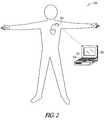
- FIG. 2is an illustration of a system 200 that includes an external device 205 used to program parameters of an IMD 210 .
- the external device 205includes a programming interface such as a display 215 and/or a keyboard 220 or computer mouse.
- the external device 205communicates with the IMD 210 wirelessly.
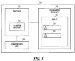
- FIG. 3is a block diagram of an example of a system that includes an external device 300 to program operating parameters into an IMD.
- the external device 300includes a communication unit 305 to communicate information with the IMD.
- the communication unit 305is configured to facilitate the communication by including any combination of hardware, firmware, or software.
- the external device 300includes a programming interface 310 , which includes a display 315 .
- the external device 300also includes a processor 320 communicatively coupled to the communication unit 305 and the programming interface 310 .
- the processor 320may include a digital signal processor, application specific integrated circuit (ASIC), microprocessor, or other type of processor, interpreting or executing instructions in software or firmware.
- ASICapplication specific integrated circuit
- the processor 320includes a parameter analyzer 325 to apply a rule to a combination of operating parameter values for an IMD to determine operating parameter interaction.
- a usertypically enters or otherwise specifies a first set of desired parameter values for the IMD.
- the rule applied by the parameter analyzer 325creates one or more interdependencies between different programmable parameters using a set of parameter interaction constraints. These constraints will restrict which values are acceptable for the user-specified first set of parameter values.
- the user specified first set of parameter valuesis automatically checked against such constraints to ensure that the user-specified set of parameter values are acceptable before they are programmed into the IMD.
- the IMD manufacturertypically defines such restrictions, such as based on safe operating conditions for the IMD.
- the automatic comparison of the first set of parameter values to the parameter interaction constraintsmay result in a first set of one or more constraint violations.
- the parameter analyzer 325uses the constraint violations to categorize combinations of operating parameters into multiple categories (e.g., those that are not allowed, those that are allowed but not recommended, and those that are allowed and result in no constraint).
- the display 315includes a first warning 330 that is displayed when a disallowed combination or set of operating parameter values is entered via the programming interface.
- a combination of operating parametersis not allowed when the combination may result in the IMD functioning incorrectly. For example, if the user tries to program a device lower rate limit (LRL) greater than the maximum tracking rate (MTR), the combination is not allowed.
- a combination of operating parametersis also not allowed when the parameter analyzer 325 determines that the combination may put a patient's safety at risk.
- the processor 320does not allow the operating parameters associated with the first warning 330 to be programmed into the IMD.
- the display 315includes a second warning 335 that is displayed when an allowable but not recommended combination of operating parameter values is entered via the programming interface 310 .
- a combination of operating parametersis allowable but not recommended when the parameter analyzer 325 determines that the combination may result in a reduction in expected efficacy of therapy or diagnostics provided by the IMD.
- the first warning 330includes a display of the word “error” or “warning,” while the second warning 335 includes a display of the word “attention.”
- the display 315uses a first color to display the first warning 330 (e.g., red) and a different second color to display the second warning 335 (e.g., yellow).
- the display 315inhibits the display of the operating parameter values associated with the first warning or the second warning when displaying at least one of the first warning and the second warning.
- the display 315alters the display of the operating parameter values associated with the first warning 330 or the second warning 335 when displaying at least one of the first warning and the second warning. For instance, the display 315 may “ghost” or the operating parameter values by displaying the parameters at a lower intensity.
- the second warning 335may be overridden.
- the processor 320programs the operating parameter values associated with the second warning 335 into the IMD only after a user acknowledgement of the second warning is received from a user via the programming interface. Without the acknowledgement from the user, the operating parameter values associated with the second warning 335 are treated as not allowed and are not programmed into the IMD.
- This programming limitationprevents the user from pushing past the conflicts in the selected set of operating parameters until the user overrides the limitation by acknowledging and accepting the patient risk.
- the operating parametersare not displayed until the user acknowledges and accepts the patient risk.
- the operating parametersare ghosted until the user acknowledges and accepts the patient risk.
- the second warning 335includes text.
- the processor 320programs the operating parameter values associated with the second warning 335 into the IMD only after receiving an acknowledgement of the second warning 335 that indicates the user read the text.
- the processor 320may receive the acknowledgement via the programming interface 310 such as by a keyboard, keypad, touch screen, computer mouse, or the like.
- the second warning 335includes educational text concerning a risk to the patient from the entered combination of operating parameters.
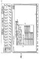
- FIG. 4is an illustration of an example of a programming interface display screen 400 for an external device used to program an IMD.
- the exampleshows a user selecting a Rhythm ID Temporary Lower Rate Limit of 45 pulses per minute (ppm).
- a text box 405containing educational text concerning the IMD parameter is displayed.
- the displaymay include an indication that there is no risk to the patient caused by the selection.
- the display screen 400may display an OK indication 410 .
- the indicationis displayed using a color (e.g., green) different from a color used to display a violation. Because the selection does not result in risk or other violation, the user is not required to check a risk disclaimer box 415 before programming the parameter into the IMD.
- FIG. 5is an illustration of another example of a programming interface display screen 500 for an external device used to program an IMD.
- the exampleshows a user selecting a Rhythm ID Temporary Lower Rate Limit of 95 ppm.
- a text box 505 containing educational text concerning the IMD parameteris displayed.
- the display screenincludes a warning 510 that the selection results in a combination of operating parameter values that are allowable but not recommended. Because the selection may result in risk to the patient, the user is required to check the risk disclaimer box 515 before the parameter or parameters are allowed to be programmed into the IMD.
- the usermay be selecting a set of operating parameters that sacrifices bradycardia pacing for tachyarrhythmia sensing.
- the textinforms the user of the IMD operation and the user can make an informed decision about whether to program more pacing at the expense of tachy sensing, or more tachy sensing with less pacing.
- the textincludes an explanation of the risk involved in the programming and is displayed at the time of parameter selection. The user then actively chooses between the risks involved to provide the best therapy for the patient using their professional judgment.
- FIG. 6shows a flow diagram of an example of a method 600 of overriding programming limitations on operating parameters for an IMD.
- a combination of operating parameter values for an IMDis received from a user at an external device.
- a ruleis applied to the combination of operating parameter values to determine operating parameter interaction.
- a first warningis displayed when a disallowed combination of operating parameter values is received from the user.
- a second warningis displayed when an allowable but not recommended combination of operating parameter values is received from the user at the external device.
- the combination of operating parameter values associated with the second level warningis enabled to be programmed into the IMD only after receiving from the user a user acknowledgement of the second warning.
- FIG. 7shows a block diagram of another example of a system 700 to program operating parameters into an IMD 710 .
- the system 700includes a repeater 730 and an external device 705 .
- the repeater 730includes a communication unit 735 configured to communicate information with the IMD 710 and the external device 705 .
- the repeater 730is local to the IMD 710 , such as by being in the same room as the patient for example.
- the repeater 730communicates with the external device 705 via a computer network 740 .
- the external device 705may access the computer network 740 through a central server 745 .
- the repeater 730may access the computer network 740 through a local computer 750 .
- the repeater 730communicates with the external device 705 via a cell phone network.
- the external device 705includes a programming interface to program operating parameters into the IMD 710 .
- the IMD 710includes a therapy unit 755 configured to provide bradycardia pacing therapy and/or cardioversion/defibrillation therapy to a patient, and a detection unit 760 to detect tachyarrhythmia in the patient.
- the parameter analyzer 325determines that a combination of operating parameter values is not allowed and/or determines that a combination is allowable but not recommended using information about whether the programming interface 310 is local to or remote from the IMD.
- the programming interfaceis local to the IMD when the external device 300 communicates with the IMD directly.
- the programming interface 310is remote from the IMD when the external device 300 communicates with the IMD using a third device such as the repeater shown in FIG. 7 .
- the parameter analyzer 325may determine that an operating parameter set selected by a user is not allowed whether programmed in a clinical setting or programmed remotely.
- the usermay try to set the minimum dynamic ventricular refractory period plus 90 milliseconds (Min Dynamic VRP+90 ms) greater than the upper rate limit (URL) in ms.
- Min Dynamic VRP+90 msminimum dynamic ventricular refractory period plus 90 milliseconds
- URLupper rate limit
- the parameter analyzer 325may determine that an operating parameter set selected by a user is allowable but not recommended when in a clinical setting and not allowed when selected remotely.
- a usermay select an operating parameter set that reduces the right ventricle (RV) pacing amplitude by 25%. Reducing the RV pacing amplitude may result in the IMD not providing ventricular contractions. This may be allowable in a clinical setting because the clinician may easily observe whether the programming affects the patient adversely, such as by causing syncope for example.
- RVright ventricle
- the parameter analyzer 325identifies a different combination of operating parameters as being allowable but not recommended when the programming is in a clinical setting and the external device 300 communicates with the IMD directly than when the programming is remote.
- the userselects to extend the atrial-ventricular delay (A-V Delay) to such an extent that pacing by the IMD is inhibited. This may also be deemed by the parameter analyzer 325 to be allowable but not recommended in a clinical setting and not allowed when programmed remotely.
- the first warning 330 and the second warning 335include text, and the text content is a function of whether the programming interface is local to the NMD in a clinical setting or remote from the ND.
- the first warning displayed when a user remotely programs a reduced RV pacing amplitude by 25%may include text explaining that the programming is not allowed to the risk of syncope in the patient. Such text may not be included in the second warning displayed when the programming is in a clinical setting.
- the clinicianis allowed to program the operating parameters after the external device 300 displays the second warning 335 and the clinician acknowledges the risk, thereby allowing the clinician to use their professional judgment in programming the device. Note that because the same combination of parameters may be allowable in a clinical setting but not allowed in a remote setting, the constraints determined by the parameter analyzer 325 may result in more first warnings 330 for a remote programming session than for a programming session in a clinical setting.
- the parameter analyzer 325may determine that an operating parameter combination selected by a user is allowable but not recommended when selected either remotely or in a clinical setting.
- a usermay select an operating parameter combination that sets a tachyarrhythmia rate detection zone interval (ms) greater than the lower rate limit interval (ms) minus the atrial-ventricular delay (Tachy Rate Zone interval>LRL ⁇ AV Delay).
- Such an operating parameter setwould cause the IMD to provide pacing pulses within the Tachy Rate Zone and would be allowable but not recommended whether in a clinical setting or when programming remotely.
- the parameter analyzer 325may determine that an operating parameter set selected by a user is allowed when in a clinical setting and allowable but not recommended when selected remotely.
- a current set of operating parameter valuesmay include a LRL of 60 ppm and a user may select to reduce the LRL by 15%. Because reducing the LRL may compromise efficacy of the IMD, this selection may be allowed in a clinical setting, but may be deemed allowable but not recommended when programming remotely.
- the display 315may display an OK indication.
- the useris allowed to program the operating parameters after the external device 300 displays the second warning 335 and the clinician acknowledges the risk. Note that the constraints determined by the parameter analyzer 325 may result in more second warnings 335 for a remote programming session than for a programming session in a clinical setting.
- the programming interface 310is local to or remote from the IND can be furnished by the user or can be obtained by the external device 300 at the time of the programming.
- the external device 300may transmit a message and a receiving device identifies itself in a response message.
- the parameter analyzer 325includes more than one rule to apply to operating parameters to determine constraints, and applies a different rule when the external device 300 is local to the IMD than when the external device is remote from the external device 300 .
- the parameter analyzer 325identifies parameter interaction constraints that may result in a first set of one or more constraint violations.
- the external device 300uses the constraints to limit the combination of operating parameters available to the user.
- the constraint violations and thus the combination limitsmay vary depending on whether the parameters are being programmed in a local or a remote programming session.
- the external device 300provides a flexible interactive limit override for the operating parameters. Flexible interactive limit control improves patient safety and promotes conscious decision making from physicians when the patient's condition may cause the physician to desire conflicting device settings.
- Method examples described hereincan be machine or computer-implemented at least in part. Some examples can include a computer-readable medium or machine-readable medium encoded with instructions operable to configure an electronic device to perform methods as described in the above examples.
- An implementation of such methodscan include code, such as microcode, assembly language code, a higher-level language code, or the like. Such code can include computer readable instructions for performing various methods. The code may form portions of computer program products. Further, the code may be tangibly stored on one or more volatile or non-volatile computer-readable media during execution or at other times.
- These computer-readable mediamay include, but are not limited to, hard disks, removable magnetic disks, removable optical disks (e.g., compact disks and digital video disks), magnetic cassettes, memory cards or sticks, random access memories (RAM's), read only memories (ROM's), and the like.
Landscapes
- Health & Medical Sciences (AREA)
- Engineering & Computer Science (AREA)
- Biomedical Technology (AREA)
- General Health & Medical Sciences (AREA)
- Public Health (AREA)
- Nuclear Medicine, Radiotherapy & Molecular Imaging (AREA)
- Veterinary Medicine (AREA)
- Animal Behavior & Ethology (AREA)
- Life Sciences & Earth Sciences (AREA)
- Radiology & Medical Imaging (AREA)
- General Business, Economics & Management (AREA)
- Primary Health Care (AREA)
- Medical Informatics (AREA)
- Epidemiology (AREA)
- Business, Economics & Management (AREA)
- Human Computer Interaction (AREA)
- Electrotherapy Devices (AREA)
Abstract
Description
Claims (15)
Priority Applications (1)
| Application Number | Priority Date | Filing Date | Title |
|---|---|---|---|
| US11/865,506US8121689B2 (en) | 2007-10-01 | 2007-10-01 | Proactive interactive limits override for implantable medical device user interface |
Applications Claiming Priority (1)
| Application Number | Priority Date | Filing Date | Title |
|---|---|---|---|
| US11/865,506US8121689B2 (en) | 2007-10-01 | 2007-10-01 | Proactive interactive limits override for implantable medical device user interface |
Publications (2)
| Publication Number | Publication Date |
|---|---|
| US20090088815A1 US20090088815A1 (en) | 2009-04-02 |
| US8121689B2true US8121689B2 (en) | 2012-02-21 |
Family
ID=40509259
Family Applications (1)
| Application Number | Title | Priority Date | Filing Date |
|---|---|---|---|
| US11/865,506Expired - Fee RelatedUS8121689B2 (en) | 2007-10-01 | 2007-10-01 | Proactive interactive limits override for implantable medical device user interface |
Country Status (1)
| Country | Link |
|---|---|
| US (1) | US8121689B2 (en) |
Cited By (14)
| Publication number | Priority date | Publication date | Assignee | Title |
|---|---|---|---|---|
| US8287495B2 (en) | 2009-07-30 | 2012-10-16 | Tandem Diabetes Care, Inc. | Infusion pump system with disposable cartridge having pressure venting and pressure feedback |
| US9486571B2 (en) | 2013-12-26 | 2016-11-08 | Tandem Diabetes Care, Inc. | Safety processor for wireless control of a drug delivery device |
| US9737656B2 (en) | 2013-12-26 | 2017-08-22 | Tandem Diabetes Care, Inc. | Integration of infusion pump with remote electronic device |
| US10049768B2 (en) | 2002-02-28 | 2018-08-14 | Tandem Diabetes Care, Inc. | Programmable insulin pump |
| USD864218S1 (en) | 2018-08-20 | 2019-10-22 | Tandem Diabetes Care, Inc. | Display screen or portion thereof with graphical user interface |
| USD864219S1 (en) | 2018-08-20 | 2019-10-22 | Tandem Diabetes Care, Inc. | Display screen or portion thereof with graphical user interface |
| USD864217S1 (en) | 2018-08-20 | 2019-10-22 | Tandem Diabetes Care, Inc. | Display screen or portion thereof with graphical user interface |
| USD875767S1 (en) | 2018-08-23 | 2020-02-18 | Tandem Diabetes Care, Inc. | Display screen or portion thereof with graphical user interface |
| USD875766S1 (en) | 2018-08-10 | 2020-02-18 | Tandem Diabetes Care, Inc. | Display screen or portion thereof with graphical user interface |
| USD875765S1 (en) | 2018-08-10 | 2020-02-18 | Tandem Diabetes Care, Inc. | Display screen or portion thereof with graphical user interface |
| USD880496S1 (en) | 2018-08-20 | 2020-04-07 | Tandem Diabetes Care, Inc. | Display screen or portion thereof with graphical user interface |
| USD882622S1 (en) | 2018-08-22 | 2020-04-28 | Tandem Diabetes Care, Inc. | Display screen or portion thereof with graphical user interface |
| USD931306S1 (en) | 2020-01-20 | 2021-09-21 | Tandem Diabetes Care, Inc. | Display screen or portion thereof with graphical user interface |
| USD938457S1 (en) | 2013-03-13 | 2021-12-14 | Tandem Diabetes Care, Inc. | Medical device display screen or portion thereof with graphical user interface |
Families Citing this family (1)
| Publication number | Priority date | Publication date | Assignee | Title |
|---|---|---|---|---|
| US20240221878A1 (en)* | 2022-12-30 | 2024-07-04 | Cilag Gmbh International | Adaptable operation range for a surgical device |
Citations (60)
| Publication number | Priority date | Publication date | Assignee | Title |
|---|---|---|---|---|
| US4208008A (en) | 1978-11-06 | 1980-06-17 | Medtronic, Inc. | Pacing generator programming apparatus including error detecting means |
| US4432360A (en) | 1981-07-06 | 1984-02-21 | Cordis Corporation | Interactive programmer for biomedical implantable devices |
| US4809697A (en) | 1987-10-14 | 1989-03-07 | Siemens-Pacesetter, Inc. | Interactive programming and diagnostic system for use with implantable pacemaker |
| US5159926A (en)* | 1989-08-28 | 1992-11-03 | Siemens Aktiengesellschaft | Medical stimulation and/or monitoring device interacting with the body of a patient based upon selectable parameter set |
| US5215083A (en) | 1991-10-07 | 1993-06-01 | Telectronics Pacing Systems, Inc. | Apparatus and method for arrhythmia induction in arrhythmia control system |
| US5267346A (en) | 1990-11-14 | 1993-11-30 | Fujitsu Limited | Combination problem solving apparatus |
| US5292341A (en) | 1992-03-02 | 1994-03-08 | Siemens Pacesetter, Inc. | Method and system for determining and automatically adjusting the sensor parameters of a rate-responsive pacemaker |
| US5360437A (en) | 1991-10-31 | 1994-11-01 | Medtronic, Inc. | Implantable medical device with flexible hardware platform |
| US5379776A (en) | 1993-04-01 | 1995-01-10 | Telectronics Pacing Systems, Inc. | Heart rhythm classification method, and implantable dual chamber cardioverter/defibrillator employing the same |
| US5496351A (en) | 1993-10-05 | 1996-03-05 | Sorin Biomedica S.P.A. | Device for determining myocardial function and corresponding procedure |
| US5507786A (en) | 1994-04-14 | 1996-04-16 | Pacesetter, Inc. | System and method for measuring and storing parametric data pertaining to operating characteristics of an implantable medical device |
| US5523942A (en) | 1994-03-31 | 1996-06-04 | New England Mutual Life Insurance Company | Design grid for inputting insurance and investment product information in a computer system |
| US5549654A (en) | 1994-04-15 | 1996-08-27 | Medtronic, Inc. | Interactive interpretation of event markers in body-implantable medical device |
| US5607460A (en) | 1996-03-15 | 1997-03-04 | Angeion Corporation | Physician interface expert system for programming implantable arrythmia treatment devices |
| US5609612A (en) | 1993-10-05 | 1997-03-11 | Sorin Biomedica Cardio S.P.A. | Device for determining myocardial function and corresponding procedure and method |
| US5620471A (en) | 1995-06-16 | 1997-04-15 | Pacesetter, Inc. | System and method for discriminating between atrial and ventricular arrhythmias and for applying cardiac therapy therefor |
| US5636328A (en) | 1993-03-22 | 1997-06-03 | Lucent Technologies Inc. | Methods and apparatus for constraint satisfaction |
| US5713937A (en) | 1995-11-07 | 1998-02-03 | Pacesetter, Inc. | Pacemaker programmer menu with selectable real or simulated implant data graphics |
| US5716382A (en) | 1995-08-02 | 1998-02-10 | Pacesetter, Inc. | Programmer for an implantable cardiac stimulating device |
| US5716384A (en) | 1996-07-08 | 1998-02-10 | Pacesetter, Inc. | Method and system for organizing, viewing and manipulating information in implantable device programmer |
| US5722999A (en) | 1995-08-02 | 1998-03-03 | Pacesetter, Inc. | System and method for storing and displaying historical medical data measured by an implantable medical device |
| US5724985A (en) | 1995-08-02 | 1998-03-10 | Pacesetter, Inc. | User interface for an implantable medical device using an integrated digitizer display screen |
| US5725559A (en) | 1996-05-16 | 1998-03-10 | Intermedics Inc. | Programmably upgradable implantable medical device |
| US5749907A (en) | 1997-02-18 | 1998-05-12 | Pacesetter, Inc. | System and method for identifying and displaying medical data which violate programmable alarm conditions |
| US5755736A (en) | 1996-05-14 | 1998-05-26 | Medtronic, Inc. | Prioritized rule based method and apparatus for diagnosis and treatment of arrhythmias |
| US5759199A (en) | 1995-08-02 | 1998-06-02 | Pacesetter, Inc. | System and method for ambulatory monitoring and programming of an implantable medical device |
| US5785660A (en) | 1996-03-28 | 1998-07-28 | Pacesetter, Inc. | Methods and apparatus for storing intracardiac electrograms |
| US5792204A (en) | 1996-05-08 | 1998-08-11 | Pacesetter, Inc. | Methods and apparatus for controlling an implantable device programmer using voice commands |
| US5836989A (en) | 1996-12-26 | 1998-11-17 | Medtronic, Inc. | Method and apparatus for controlling an implanted medical device in a time-dependent manner |
| US5839989A (en) | 1996-04-30 | 1998-11-24 | Honda Giken Kogyo Kabushiki Kaisha | Control system for throttle released shifting by synchronous throttle control of an internal combustion engines |
| US5843138A (en) | 1997-07-09 | 1998-12-01 | Vitatron Medical, B.V. | Pacemaker system with enhanced programmable modification capacity |
| US5891178A (en) | 1996-05-14 | 1999-04-06 | Pacesetter, Inc. | Programmer system and associated methods for rapidly evaluating and programming an implanted cardiac device |
| US5908392A (en) | 1996-03-13 | 1999-06-01 | Pacesetter, Inc. | System and method for recording and storing medical data in response to a programmable trigger |
| US5978707A (en) | 1997-04-30 | 1999-11-02 | Cardiac Pacemakers, Inc. | Apparatus and method for treating ventricular tachyarrhythmias |
| US6004020A (en) | 1997-06-11 | 1999-12-21 | Bartur; Meir | Medication dispensing and monitoring system |
| US6016442A (en) | 1998-03-25 | 2000-01-18 | Cardiac Pacemakers, Inc. | System for displaying cardiac arrhythmia data |
| US6031984A (en) | 1998-03-09 | 2000-02-29 | I2 Technologies, Inc. | Method and apparatus for optimizing constraint models |
| US6045513A (en) | 1998-05-13 | 2000-04-04 | Medtronic, Inc. | Implantable medical device for tracking patient functional status |
| US6088618A (en) | 1998-07-07 | 2000-07-11 | Vitatron Medical, B.V. | Pacemaker system and method for providing manual display concurrent with pacemaker software modification |
| US6101416A (en) | 1998-07-29 | 2000-08-08 | Pacesetter, Inc. | System and method for atrial autocapture in single-chamber pacemaker modes using far-field detection |
| US6289248B1 (en) | 1999-08-20 | 2001-09-11 | Cardiac Pacemakers, Inc. | System and method for detecting and displaying parameter interactions |
| US20020091308A1 (en)* | 2001-01-09 | 2002-07-11 | Kipshidze Nicholas N. | Method and apparatus for the synchronized therapeutic treatment of a life form |
| US20020143372A1 (en)* | 2001-03-29 | 2002-10-03 | Snell Jeffery D. | System and method for remote programming of implantable cardiac stimulation devices |
| US20020156389A1 (en) | 2001-02-28 | 2002-10-24 | Cardiac Pacemakers, Inc. | Cardiac rhythm management patient report |
| US20030125776A1 (en) | 2001-12-28 | 2003-07-03 | Turney Jerry L. | Mechanical metaphor for representing paramater constraints graphically for medical devices |
| US6700097B1 (en) | 2001-09-28 | 2004-03-02 | Lincoln Global, Inc. | Electric ARC welder and controller to design the waveform therefor |
| US20040111131A1 (en) | 2002-12-05 | 2004-06-10 | Bo Hu | Cardiac rhythm management systems and methods for rule-illustrative parameter entry |
| US6842644B2 (en) | 2001-11-02 | 2005-01-11 | Cardiac Pacemakers, Inc. | User navigation and guidance during configuration and storage of parameters for medical device |
| US20050010388A1 (en) | 2003-07-11 | 2005-01-13 | International Business Machines Corporation | Dynamic online multi-parameter optimization system and method for autonomic computing systems |
| US20050010258A1 (en) | 2003-05-07 | 2005-01-13 | Peterson Les Norman | Medical device interface system and method |
| US20050033385A1 (en) | 2003-05-07 | 2005-02-10 | Peterson Les Norman | Implantable medical device programming apparatus having a graphical user interface |
| US20050060198A1 (en) | 2000-07-06 | 2005-03-17 | Bayne Cary Gresham | Method for clinician house calls utilizing portable computing and communications equipment |
| US20050060008A1 (en)* | 2003-09-15 | 2005-03-17 | Goetz Steven M. | Selection of neurostimulator parameter configurations using bayesian networks |
| US20050216064A1 (en)* | 2004-03-16 | 2005-09-29 | Heruth Kenneth T | Sensitivity analysis for selecting therapy parameter sets |
| US7003349B1 (en) | 1999-12-16 | 2006-02-21 | St. Jude Medical Ab | Programming system for medical devices |
| US20060111759A1 (en)* | 2004-11-19 | 2006-05-25 | Hoyme Kenneth P | System and method for temporary programming for implanted medical devices |
| US7089221B2 (en) | 2003-06-24 | 2006-08-08 | Palo Alto Research Center Incorporated | Feedback control of problem solving |
| US20060241822A1 (en) | 2005-04-25 | 2006-10-26 | Oracle International Corporation | Optimization of carrier selection for transportation planning system |
| US20080126968A1 (en) | 2006-04-27 | 2008-05-29 | Jeff West | Medical device user interface automatically resolving interaction between programmable parameters |
| US20080269812A1 (en)* | 2007-04-30 | 2008-10-30 | Medtronic, Inc. | Therapy adjustment |
- 2007
- 2007-10-01USUS11/865,506patent/US8121689B2/ennot_activeExpired - Fee Related
Patent Citations (69)
| Publication number | Priority date | Publication date | Assignee | Title |
|---|---|---|---|---|
| US4208008A (en) | 1978-11-06 | 1980-06-17 | Medtronic, Inc. | Pacing generator programming apparatus including error detecting means |
| US4432360A (en) | 1981-07-06 | 1984-02-21 | Cordis Corporation | Interactive programmer for biomedical implantable devices |
| US4809697A (en) | 1987-10-14 | 1989-03-07 | Siemens-Pacesetter, Inc. | Interactive programming and diagnostic system for use with implantable pacemaker |
| US5159926A (en)* | 1989-08-28 | 1992-11-03 | Siemens Aktiengesellschaft | Medical stimulation and/or monitoring device interacting with the body of a patient based upon selectable parameter set |
| US5267346A (en) | 1990-11-14 | 1993-11-30 | Fujitsu Limited | Combination problem solving apparatus |
| US5215083A (en) | 1991-10-07 | 1993-06-01 | Telectronics Pacing Systems, Inc. | Apparatus and method for arrhythmia induction in arrhythmia control system |
| US5360437A (en) | 1991-10-31 | 1994-11-01 | Medtronic, Inc. | Implantable medical device with flexible hardware platform |
| US5292341A (en) | 1992-03-02 | 1994-03-08 | Siemens Pacesetter, Inc. | Method and system for determining and automatically adjusting the sensor parameters of a rate-responsive pacemaker |
| US5636328A (en) | 1993-03-22 | 1997-06-03 | Lucent Technologies Inc. | Methods and apparatus for constraint satisfaction |
| US5379776A (en) | 1993-04-01 | 1995-01-10 | Telectronics Pacing Systems, Inc. | Heart rhythm classification method, and implantable dual chamber cardioverter/defibrillator employing the same |
| US5693075A (en) | 1993-10-05 | 1997-12-02 | Sorin Biomedica S.P.A. | Device for determining myocardial function and corresponding procedure |
| US5609612A (en) | 1993-10-05 | 1997-03-11 | Sorin Biomedica Cardio S.P.A. | Device for determining myocardial function and corresponding procedure and method |
| US5496351A (en) | 1993-10-05 | 1996-03-05 | Sorin Biomedica S.P.A. | Device for determining myocardial function and corresponding procedure |
| US5523942A (en) | 1994-03-31 | 1996-06-04 | New England Mutual Life Insurance Company | Design grid for inputting insurance and investment product information in a computer system |
| US5507786A (en) | 1994-04-14 | 1996-04-16 | Pacesetter, Inc. | System and method for measuring and storing parametric data pertaining to operating characteristics of an implantable medical device |
| US5549654A (en) | 1994-04-15 | 1996-08-27 | Medtronic, Inc. | Interactive interpretation of event markers in body-implantable medical device |
| US5620471A (en) | 1995-06-16 | 1997-04-15 | Pacesetter, Inc. | System and method for discriminating between atrial and ventricular arrhythmias and for applying cardiac therapy therefor |
| US5724985A (en) | 1995-08-02 | 1998-03-10 | Pacesetter, Inc. | User interface for an implantable medical device using an integrated digitizer display screen |
| US5716382A (en) | 1995-08-02 | 1998-02-10 | Pacesetter, Inc. | Programmer for an implantable cardiac stimulating device |
| US5722999A (en) | 1995-08-02 | 1998-03-03 | Pacesetter, Inc. | System and method for storing and displaying historical medical data measured by an implantable medical device |
| US5759199A (en) | 1995-08-02 | 1998-06-02 | Pacesetter, Inc. | System and method for ambulatory monitoring and programming of an implantable medical device |
| US5713937A (en) | 1995-11-07 | 1998-02-03 | Pacesetter, Inc. | Pacemaker programmer menu with selectable real or simulated implant data graphics |
| US5908392A (en) | 1996-03-13 | 1999-06-01 | Pacesetter, Inc. | System and method for recording and storing medical data in response to a programmable trigger |
| US5607460A (en) | 1996-03-15 | 1997-03-04 | Angeion Corporation | Physician interface expert system for programming implantable arrythmia treatment devices |
| US5785660A (en) | 1996-03-28 | 1998-07-28 | Pacesetter, Inc. | Methods and apparatus for storing intracardiac electrograms |
| US5839989A (en) | 1996-04-30 | 1998-11-24 | Honda Giken Kogyo Kabushiki Kaisha | Control system for throttle released shifting by synchronous throttle control of an internal combustion engines |
| US5792204A (en) | 1996-05-08 | 1998-08-11 | Pacesetter, Inc. | Methods and apparatus for controlling an implantable device programmer using voice commands |
| US5755736A (en) | 1996-05-14 | 1998-05-26 | Medtronic, Inc. | Prioritized rule based method and apparatus for diagnosis and treatment of arrhythmias |
| US5891178A (en) | 1996-05-14 | 1999-04-06 | Pacesetter, Inc. | Programmer system and associated methods for rapidly evaluating and programming an implanted cardiac device |
| US5725559A (en) | 1996-05-16 | 1998-03-10 | Intermedics Inc. | Programmably upgradable implantable medical device |
| US5716384A (en) | 1996-07-08 | 1998-02-10 | Pacesetter, Inc. | Method and system for organizing, viewing and manipulating information in implantable device programmer |
| US5836989A (en) | 1996-12-26 | 1998-11-17 | Medtronic, Inc. | Method and apparatus for controlling an implanted medical device in a time-dependent manner |
| US5749907A (en) | 1997-02-18 | 1998-05-12 | Pacesetter, Inc. | System and method for identifying and displaying medical data which violate programmable alarm conditions |
| US5978707A (en) | 1997-04-30 | 1999-11-02 | Cardiac Pacemakers, Inc. | Apparatus and method for treating ventricular tachyarrhythmias |
| US6004020A (en) | 1997-06-11 | 1999-12-21 | Bartur; Meir | Medication dispensing and monitoring system |
| US5843138A (en) | 1997-07-09 | 1998-12-01 | Vitatron Medical, B.V. | Pacemaker system with enhanced programmable modification capacity |
| US6031984A (en) | 1998-03-09 | 2000-02-29 | I2 Technologies, Inc. | Method and apparatus for optimizing constraint models |
| US6091990A (en) | 1998-03-25 | 2000-07-18 | Cardiac Pacemakers, Inc. | System for grouping and displaying cardiac arrhythmia data |
| US6016442A (en) | 1998-03-25 | 2000-01-18 | Cardiac Pacemakers, Inc. | System for displaying cardiac arrhythmia data |
| US6045513A (en) | 1998-05-13 | 2000-04-04 | Medtronic, Inc. | Implantable medical device for tracking patient functional status |
| US6088618A (en) | 1998-07-07 | 2000-07-11 | Vitatron Medical, B.V. | Pacemaker system and method for providing manual display concurrent with pacemaker software modification |
| US6101416A (en) | 1998-07-29 | 2000-08-08 | Pacesetter, Inc. | System and method for atrial autocapture in single-chamber pacemaker modes using far-field detection |
| US6289248B1 (en) | 1999-08-20 | 2001-09-11 | Cardiac Pacemakers, Inc. | System and method for detecting and displaying parameter interactions |
| US20020049481A1 (en) | 1999-08-20 | 2002-04-25 | Cardiac Pacemakers, Inc. | System and method for detecting and displaying parameter interactions |
| US7010349B2 (en) | 1999-08-20 | 2006-03-07 | Cardiac Pacemakers, Inc. | System and method for detecting and displaying parameter interactions |
| US20040116982A1 (en) | 1999-08-20 | 2004-06-17 | Cardiac Pacemakers, Inc. | System and method for detecting and displaying parameter interactions |
| US6690972B2 (en) | 1999-08-20 | 2004-02-10 | Cardiac Pacemakers, Inc. | System and method for detecting and displaying parameter interactions |
| US7003349B1 (en) | 1999-12-16 | 2006-02-21 | St. Jude Medical Ab | Programming system for medical devices |
| US20050060198A1 (en) | 2000-07-06 | 2005-03-17 | Bayne Cary Gresham | Method for clinician house calls utilizing portable computing and communications equipment |
| US20020091308A1 (en)* | 2001-01-09 | 2002-07-11 | Kipshidze Nicholas N. | Method and apparatus for the synchronized therapeutic treatment of a life form |
| US20020156389A1 (en) | 2001-02-28 | 2002-10-24 | Cardiac Pacemakers, Inc. | Cardiac rhythm management patient report |
| US20020143372A1 (en)* | 2001-03-29 | 2002-10-03 | Snell Jeffery D. | System and method for remote programming of implantable cardiac stimulation devices |
| US6700097B1 (en) | 2001-09-28 | 2004-03-02 | Lincoln Global, Inc. | Electric ARC welder and controller to design the waveform therefor |
| US6842644B2 (en) | 2001-11-02 | 2005-01-11 | Cardiac Pacemakers, Inc. | User navigation and guidance during configuration and storage of parameters for medical device |
| US20030125776A1 (en) | 2001-12-28 | 2003-07-03 | Turney Jerry L. | Mechanical metaphor for representing paramater constraints graphically for medical devices |
| US20040111131A1 (en) | 2002-12-05 | 2004-06-10 | Bo Hu | Cardiac rhythm management systems and methods for rule-illustrative parameter entry |
| US7191006B2 (en) | 2002-12-05 | 2007-03-13 | Cardiac Pacemakers, Inc. | Cardiac rhythm management systems and methods for rule-illustrative parameter entry |
| US7272444B2 (en) | 2003-05-07 | 2007-09-18 | Cardiac Pacemakers, Inc. | Medical device interface system with automatic rate threshold adjustment |
| US20050010258A1 (en) | 2003-05-07 | 2005-01-13 | Peterson Les Norman | Medical device interface system and method |
| US20050033385A1 (en) | 2003-05-07 | 2005-02-10 | Peterson Les Norman | Implantable medical device programming apparatus having a graphical user interface |
| US7089221B2 (en) | 2003-06-24 | 2006-08-08 | Palo Alto Research Center Incorporated | Feedback control of problem solving |
| US20050010388A1 (en) | 2003-07-11 | 2005-01-13 | International Business Machines Corporation | Dynamic online multi-parameter optimization system and method for autonomic computing systems |
| US20050060008A1 (en)* | 2003-09-15 | 2005-03-17 | Goetz Steven M. | Selection of neurostimulator parameter configurations using bayesian networks |
| US20050216064A1 (en)* | 2004-03-16 | 2005-09-29 | Heruth Kenneth T | Sensitivity analysis for selecting therapy parameter sets |
| US20060111759A1 (en)* | 2004-11-19 | 2006-05-25 | Hoyme Kenneth P | System and method for temporary programming for implanted medical devices |
| US20060241822A1 (en) | 2005-04-25 | 2006-10-26 | Oracle International Corporation | Optimization of carrier selection for transportation planning system |
| US20080126968A1 (en) | 2006-04-27 | 2008-05-29 | Jeff West | Medical device user interface automatically resolving interaction between programmable parameters |
| US7613672B2 (en) | 2006-04-27 | 2009-11-03 | Cardiac Pacemakers, Inc. | Medical device user interface automatically resolving interaction between programmable parameters |
| US20080269812A1 (en)* | 2007-04-30 | 2008-10-30 | Medtronic, Inc. | Therapy adjustment |
Non-Patent Citations (5)
Cited By (30)
| Publication number | Priority date | Publication date | Assignee | Title |
|---|---|---|---|---|
| US10049768B2 (en) | 2002-02-28 | 2018-08-14 | Tandem Diabetes Care, Inc. | Programmable insulin pump |
| US12042627B2 (en) | 2009-07-30 | 2024-07-23 | Tandem Diabetes Care, Inc. | Infusion pump systems and methods |
| US8298184B2 (en) | 2009-07-30 | 2012-10-30 | Tandem Diabetes Care, Inc. | Infusion pump system with disposable cartridge having pressure venting and pressure feedback |
| US11135362B2 (en) | 2009-07-30 | 2021-10-05 | Tandem Diabetes Care, Inc. | Infusion pump systems and methods |
| US11285263B2 (en) | 2009-07-30 | 2022-03-29 | Tandem Diabetes Care, Inc. | Infusion pump systems and methods |
| US8287495B2 (en) | 2009-07-30 | 2012-10-16 | Tandem Diabetes Care, Inc. | Infusion pump system with disposable cartridge having pressure venting and pressure feedback |
| US12144964B2 (en) | 2009-07-30 | 2024-11-19 | Tandem Diabetes Care, Inc | Infusion pump system with disposable cartridge having pressure venting and pressure feedback |
| USD938457S1 (en) | 2013-03-13 | 2021-12-14 | Tandem Diabetes Care, Inc. | Medical device display screen or portion thereof with graphical user interface |
| US12251536B2 (en) | 2013-03-13 | 2025-03-18 | Tandem Diabetes Care, Inc. | System and method for integration and display of data of insulin pumps and continuous glucose monitoring |
| US11607492B2 (en) | 2013-03-13 | 2023-03-21 | Tandem Diabetes Care, Inc. | System and method for integration and display of data of insulin pumps and continuous glucose monitoring |
| US10213547B2 (en) | 2013-12-26 | 2019-02-26 | Tandem Diabetes Care, Inc. | Safety processor for a drug delivery device |
| US11911590B2 (en) | 2013-12-26 | 2024-02-27 | Tandem Diabetes Care, Inc. | Integration of infusion pump with remote electronic device |
| US10478551B2 (en) | 2013-12-26 | 2019-11-19 | Tandem Diabetes Care, Inc. | Integration of infusion pump with remote electronic device |
| US10806851B2 (en) | 2013-12-26 | 2020-10-20 | Tandem Diabetes Care, Inc. | Wireless control of a drug delivery device |
| US10918785B2 (en) | 2013-12-26 | 2021-02-16 | Tandem Diabetes Care, Inc. | Integration of infusion pump with remote electronic device |
| US11383027B2 (en) | 2013-12-26 | 2022-07-12 | Tandem Diabetes Care, Inc. | Integration of infusion pump with remote electronic device |
| US9737656B2 (en) | 2013-12-26 | 2017-08-22 | Tandem Diabetes Care, Inc. | Integration of infusion pump with remote electronic device |
| US9486571B2 (en) | 2013-12-26 | 2016-11-08 | Tandem Diabetes Care, Inc. | Safety processor for wireless control of a drug delivery device |
| USD875766S1 (en) | 2018-08-10 | 2020-02-18 | Tandem Diabetes Care, Inc. | Display screen or portion thereof with graphical user interface |
| USD875765S1 (en) | 2018-08-10 | 2020-02-18 | Tandem Diabetes Care, Inc. | Display screen or portion thereof with graphical user interface |
| USD864219S1 (en) | 2018-08-20 | 2019-10-22 | Tandem Diabetes Care, Inc. | Display screen or portion thereof with graphical user interface |
| USD918227S1 (en) | 2018-08-20 | 2021-05-04 | Tandem Diabetes Care, Inc. | Display screen or portion thereof with graphical user interface |
| USD980232S1 (en) | 2018-08-20 | 2023-03-07 | Tandem Diabetes Care, Inc. | Display screen or portion thereof with graphical user interface |
| USD1014513S1 (en) | 2018-08-20 | 2024-02-13 | Tandem Diabetes Care, Inc. | Display screen or portion thereof with graphical user interface |
| USD880496S1 (en) | 2018-08-20 | 2020-04-07 | Tandem Diabetes Care, Inc. | Display screen or portion thereof with graphical user interface |
| USD864217S1 (en) | 2018-08-20 | 2019-10-22 | Tandem Diabetes Care, Inc. | Display screen or portion thereof with graphical user interface |
| USD864218S1 (en) | 2018-08-20 | 2019-10-22 | Tandem Diabetes Care, Inc. | Display screen or portion thereof with graphical user interface |
| USD882622S1 (en) | 2018-08-22 | 2020-04-28 | Tandem Diabetes Care, Inc. | Display screen or portion thereof with graphical user interface |
| USD875767S1 (en) | 2018-08-23 | 2020-02-18 | Tandem Diabetes Care, Inc. | Display screen or portion thereof with graphical user interface |
| USD931306S1 (en) | 2020-01-20 | 2021-09-21 | Tandem Diabetes Care, Inc. | Display screen or portion thereof with graphical user interface |
Also Published As
| Publication number | Publication date |
|---|---|
| US20090088815A1 (en) | 2009-04-02 |
Similar Documents
| Publication | Publication Date | Title |
|---|---|---|
| US8121689B2 (en) | Proactive interactive limits override for implantable medical device user interface | |
| US7966069B2 (en) | Medical device interface system with automatic rate threshold adjustment | |
| US7979378B2 (en) | Medical device user interface automatically resolving interaction between programmable parameters | |
| US8437852B2 (en) | Change log for implantable medical device | |
| EP2533854B1 (en) | Implantable medical device with an electronic prescription | |
| EP2355896B1 (en) | Multiple user accounts for managing stored information in an implantable medical device system | |
| US8548586B2 (en) | Configurable intermittent pacing therapy | |
| US9533166B2 (en) | System and method for correlation of patient health information and device data | |
| EP2490759B1 (en) | Implantable medical device with selectively configurable exposure operating mode programming options | |
| US7191006B2 (en) | Cardiac rhythm management systems and methods for rule-illustrative parameter entry | |
| US9008788B2 (en) | Enablement and/or disablement of an exposure mode of an implantable medical device | |
| US20020077562A1 (en) | System and method for correlation of patient health information and implant device data | |
| US20100249868A1 (en) | Implantable medical device programming apparatus having a graphical user interface | |
| CN112512628A (en) | Patient-mediated therapy management | |
| EP3368150B1 (en) | Multisite pacing capture determination based on evoked response | |
| US8185200B2 (en) | Disable for atrioventricular delay adjustment |
Legal Events
| Date | Code | Title | Description |
|---|---|---|---|
| AS | Assignment | Owner name:CARDIAC PACEMAKERS, INC., MINNESOTA Free format text:ASSIGNMENT OF ASSIGNORS INTEREST;ASSIGNORS:KALGREN, JAMES;PETERSON, LES;KELLY, JONATHAN H.;AND OTHERS;REEL/FRAME:020267/0001 Effective date:20070926 | |
| ZAAA | Notice of allowance and fees due | Free format text:ORIGINAL CODE: NOA | |
| ZAAB | Notice of allowance mailed | Free format text:ORIGINAL CODE: MN/=. | |
| FEPP | Fee payment procedure | Free format text:PAYOR NUMBER ASSIGNED (ORIGINAL EVENT CODE: ASPN); ENTITY STATUS OF PATENT OWNER: LARGE ENTITY | |
| STCF | Information on status: patent grant | Free format text:PATENTED CASE | |
| FPAY | Fee payment | Year of fee payment:4 | |
| MAFP | Maintenance fee payment | Free format text:PAYMENT OF MAINTENANCE FEE, 8TH YEAR, LARGE ENTITY (ORIGINAL EVENT CODE: M1552); ENTITY STATUS OF PATENT OWNER: LARGE ENTITY Year of fee payment:8 | |
| FEPP | Fee payment procedure | Free format text:MAINTENANCE FEE REMINDER MAILED (ORIGINAL EVENT CODE: REM.); ENTITY STATUS OF PATENT OWNER: LARGE ENTITY | |
| LAPS | Lapse for failure to pay maintenance fees | Free format text:PATENT EXPIRED FOR FAILURE TO PAY MAINTENANCE FEES (ORIGINAL EVENT CODE: EXP.); ENTITY STATUS OF PATENT OWNER: LARGE ENTITY | |
| STCH | Information on status: patent discontinuation | Free format text:PATENT EXPIRED DUE TO NONPAYMENT OF MAINTENANCE FEES UNDER 37 CFR 1.362 | |
| FP | Lapsed due to failure to pay maintenance fee | Effective date:20240221 |