US8121552B2 - Method and apparatus for providing channel quality feedback in a wireless communication system - Google Patents
Method and apparatus for providing channel quality feedback in a wireless communication systemDownload PDFInfo
- Publication number
- US8121552B2 US8121552B2US11/469,983US46998306AUS8121552B2US 8121552 B2US8121552 B2US 8121552B2US 46998306 AUS46998306 AUS 46998306AUS 8121552 B2US8121552 B2US 8121552B2
- Authority
- US
- United States
- Prior art keywords
- channel condition
- reporting period
- subscriber station
- condition reporting
- base station
- Prior art date
- Legal status (The legal status is an assumption and is not a legal conclusion. Google has not performed a legal analysis and makes no representation as to the accuracy of the status listed.)
- Active, expires
Links
- 238000004891communicationMethods0.000titleclaimsabstractdescription39
- 238000000034methodMethods0.000titleclaimsdescription24
- 230000004044responseEffects0.000claimsdescription13
- 238000010183spectrum analysisMethods0.000claimsdescription9
- 238000012790confirmationMethods0.000claimsdescription4
- 230000000737periodic effectEffects0.000abstractdescription6
- 238000005259measurementMethods0.000description13
- 238000010586diagramMethods0.000description10
- 230000005540biological transmissionEffects0.000description6
- 230000008859changeEffects0.000description6
- 230000008901benefitEffects0.000description5
- 230000007704transitionEffects0.000description5
- 230000009471actionEffects0.000description3
- 230000011664signalingEffects0.000description3
- 230000007423decreaseEffects0.000description2
- 230000006870functionEffects0.000description2
- 230000008569processEffects0.000description2
- 230000001413cellular effectEffects0.000description1
- 230000000694effectsEffects0.000description1
- 238000012545processingMethods0.000description1
- 238000001228spectrumMethods0.000description1
- 238000006467substitution reactionMethods0.000description1
Images


Classifications
- H—ELECTRICITY
- H04—ELECTRIC COMMUNICATION TECHNIQUE
- H04W—WIRELESS COMMUNICATION NETWORKS
- H04W24/00—Supervisory, monitoring or testing arrangements
- H04W24/10—Scheduling measurement reports ; Arrangements for measurement reports
- H—ELECTRICITY
- H04—ELECTRIC COMMUNICATION TECHNIQUE
- H04L—TRANSMISSION OF DIGITAL INFORMATION, e.g. TELEGRAPHIC COMMUNICATION
- H04L1/00—Arrangements for detecting or preventing errors in the information received
- H—ELECTRICITY
- H04—ELECTRIC COMMUNICATION TECHNIQUE
- H04L—TRANSMISSION OF DIGITAL INFORMATION, e.g. TELEGRAPHIC COMMUNICATION
- H04L1/00—Arrangements for detecting or preventing errors in the information received
- H04L1/0001—Systems modifying transmission characteristics according to link quality, e.g. power backoff
- H04L1/0023—Systems modifying transmission characteristics according to link quality, e.g. power backoff characterised by the signalling
- H04L1/0026—Transmission of channel quality indication
- H—ELECTRICITY
- H04—ELECTRIC COMMUNICATION TECHNIQUE
- H04L—TRANSMISSION OF DIGITAL INFORMATION, e.g. TELEGRAPHIC COMMUNICATION
- H04L1/00—Arrangements for detecting or preventing errors in the information received
- H04L2001/0092—Error control systems characterised by the topology of the transmission link
- H04L2001/0093—Point-to-multipoint
Definitions
- the present inventionrelates generally to wireless communication systems, and, in particular, to an exchange of channel quality information in a wireless communication system providing periodic channel quality feedback.
- OFDMAOrthogonal Frequency Division Multiple Access
- 3GPPThird Generation Partnership Project
- OFDMAOrthogonal Frequency Division Multiple Access
- a frequency bandwidthis split into multiple frequency subcarriers that comprise the physical layer channels over which traffic and signaling channels are transmitted in a TDM or TDM/FDM fashion.
- a usermay then be assigned one or more of the frequency subcarriers for an exchange of bearer information, thereby permitting multiple users to transmit simultaneously on the different set of subcarriers such that each user's transmission is orthogonal to the other users transmissions and thus intra-cell interference is minimized.
- OFDMA communication systemsIn order to maximize bandwidth usage, OFDMA communication systems often engage in frequency selective scheduling. That is, for any given radio frame, the subcarriers may be allocated to users based on measured channel conditions. Alternatively, individual subcarriers across the entire bandwidth may be assigned to users so that a user can report an average CQI across all of its assigned subcarriers. Further, an appropriate modulation scheme and coding scheme may be determined for each subcarrier and each radio frame based on the measured channel conditions.
- the channel condition measurementsare performed by a subscriber station (SS), which SS measures channel conditions for each assigned subcarrier or alternatively averages all its assigned subcarriers during a measuring period, such as a radio frame transmission period, and then reports the measured channel conditions for all of the subcarriers to a serving Node B in a Channel Quality Information (CQI) message.
- the CQI messagesare conveyed at a fixed periodicity, or rate, typically every 8 frames, that is, every 40 milliseconds (ms).
- an OFDMA communication systemBased on the reported CQIs, an OFDMA communication system selectively schedules the subcarriers each radio frame and further adaptively determines appropriate modulation and coding schemes for each subcarrier during the scheduling period.
- Reporting a CQI at a fixed periodicitymay consume a significant amount of uplink system overhead, especially when there are a large number of reporting subscriber stations (SSs).
- SSssubscriber stations
- an SSreport a CQI only when the CQI is above a threshold or is below another threshold, in effect, turning the CQI feedback channel on and off.
- such a proposaldoes not provide a base station scheduler with the CQI precision required to make optimal scheduling choices.
- FIG. 1is a block diagram of a wireless communication system in accordance with an embodiment of the present invention.
- FIG. 2is a block diagram of a subscriber station (SS) in accordance with an embodiment of the present invention.
- FIG. 3is an exemplary channel map of the channels of an air interface of FIG. 1 in accordance with an embodiment of the present invention.
- FIG. 4is a logic flow diagram depicting a control by the communication system of FIG. 1 of a channel condition reporting period for an SS of FIG. 1 in accordance with an embodiment of the present invention.
- FIG. 5is an exemplary graphical representation of Channel Quality Information (CQI) values reported by an SS of FIG. 1 in accordance with an embodiment of the present invention.
- CQIChannel Quality Information
- FIG. 6is an exemplary graphical representation of CQI values reported by an SS of FIG. 1 in accordance with another embodiment of the present invention.
- FIG. 7is an exemplary frequency domain analysis is provided of multiple CQI values reported by an SS of FIG. 1 in accordance with another embodiment of the present invention.
- FIG. 8is a logic flow diagram that depicts a method for adjusting, by a base station of FIG. 1 , a channel condition reporting period for an SS of FIG. 1 in accordance with an embodiment of the present invention.
- FIG. 9is an exemplary channel condition reporting schedule table in accordance with an embodiment of the present invention.
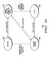
- FIG. 10depicts an exemplary state machine that may be maintained by a base station of FIG. 1 in accordance with an embodiment of the present invention.
- a wireless communication systemthat provides periodic channel quality feedback adjusts a channel condition reporting period for a subscriber station based on the multiple channel condition information reports, such as CQI messages, received from the subscriber station.
- CQIChannel Quality Information
- an embodiment of the present inventionencompasses a method for adjusting a channel condition reporting period in a wireless communication system.
- the methodincludes receiving multiple channel condition information reports from a subscriber station based on a channel condition reporting period and adjusting the channel condition reporting period for the subscriber station based on the multiple received channel condition information reports to produce an adjusted channel condition reporting period.
- Another embodiment of the present inventionencompasses a base station that is configured to control a channel condition reporting period in a wireless communication system, wherein the base station comprises a processor that is configured to receive multiple channel condition information reports from a subscriber station based on a channel condition reporting period and adjust the channel condition reporting period for the subscriber station based on the multiple received channel condition information reports to produce an adjusted channel condition reporting period.
- Yet another embodiment of the present inventionencompasses a subscriber station that is configured to convey multiple channel condition information reports to a base station based on a first channel condition reporting period, in response to conveying the plurality of channel condition information reports, receive information concerning a second channel condition reporting period that is different than the first channel condition reporting period, and, in response to receiving the information concerning the second channel condition reporting period, convey a channel condition report based on the second channel condition reporting period.
- FIG. 1is a block diagram of a wireless communication system 100 in accordance with an embodiment of the present invention.
- Communication system 100includes multiple subscriber stations (SSs) 101 - 115 , such as but not limited to a cellular telephone, a radio telephone, a personal digital assistant (PDA) with radio frequency (RF) capabilities, or a wireless modem that provides RF access to digital terminal equipment (DTE) such as a laptop computer.
- SSssubscriber stations
- PDApersonal digital assistant
- RFradio frequency
- DTEdigital terminal equipment
- Communication system 100further includes a radio access network (RAN) 130 that comprises a radio base station 132 , such as an Access Point, aNode B, or a Base Transceiver Station (BTS), that provides wireless communication services to each of SSs 101 - 115 via an air interface 120 .
- RANradio access network
- RANradio access network
- BTSBase Transceiver Station
- Base station 132includes a processor 134 , such as one or more microprocessors, microcontrollers, digital signal processors (DSPs), combinations thereof or such other devices known to those having ordinary skill in the art.
- processor 134such as one or more microprocessors, microcontrollers, digital signal processors (DSPs), combinations thereof or such other devices known to those having ordinary skill in the art.
- the particular operations/functions of processor 134are determined by an execution of software instructions and routines that are stored in an at least one memory device 136 associated with the processor, such as random access memory (RAM), dynamic random access memory (DRAM), and/or read only memory (ROM) or equivalents thereof, that store data and programs that may be executed by the corresponding processor.
- RAMrandom access memory
- DRAMdynamic random access memory
- ROMread only memory
- Processor 134further implements a fast scheduler based on instructions maintained in the associated at least one memory device 136 that allocates one or more sub-channels, data rates, and coding and modulation schemes to each subscriber station (SS) serviced by the transceiver based on channel condition measurements, preferably Channel Quality Information (CQI) measurements.
- SSsubscriber station
- CQIChannel Quality Information
- FIG. 2is a block diagram of a subscriber station (SS) 200 , such as SSs 101 - 115 , in accordance with an embodiment of the present invention.
- SS 200includes a processor 202 , such as one or more microprocessors, microcontrollers, digital signal processors (DSPs), combinations thereof or such other devices known to those having ordinary skill in the art.
- the particular operations/functions of processor 202 , and respectively thus of SS 200is determined by an execution of software instructions and routines that are stored in a respective at least one memory device 204 associated with the processor, such as random access memory (RAM), dynamic random access memory (DRAM), and/or read only memory (ROM) or equivalents thereof, that store data and programs that may be executed by the corresponding processor.
- RAMrandom access memory
- DRAMdynamic random access memory
- ROMread only memory
- the embodiments of the present inventionpreferably are implemented within SSs 101 - 115 and base station 132 , and more particularly with or in software programs and instructions stored in the respective at least one memory device 204 , 136 of the SSs and base station and respectively executed by processors 202 and 134 .
- processors 202 and 134processors 202 and 134 .
- the embodiments of the present inventionalternatively may be implemented in hardware, for example, integrated circuits (ICs), application specific integrated circuits (ASICs), and the like, such as ASICs implemented in one or more of SSs 101 - 115 and base station 132 . Based on the present disclosure, one skilled in the art will be readily capable of producing and implementing such software and/or hardware without undo experimentation.
- Communication system 100comprises a wideband packet data communication system that employs an Orthogonal Frequency Division Multiplexing (OFDM) modulation scheme for transmitting data over air interface 110 .
- communication system 100is an Orthogonal Frequency Division Multiple Access (OFDMA) communication system, wherein a frequency bandwidth is split into multiple frequency subcarriers that comprise the physical layer channels over which traffic and signaling channels are transmitted via time slots in a TDM (Time Division Multiplexed) or TDM/FDM (Time Division Multiplexed/Frequency Division Multiplexed) fashion.
- OFDMOrthogonal Frequency Division Multiple Access
- a usermay then be assigned one or more time slots in one or more of the frequency subcarriers for an exchange of bearer information, thereby permitting multiple users to transmit simultaneously on the different set of subcarriers such that each user's transmission is orthogonal to the other users transmissions and thus intra-cell interference is minimized.
- communication system 100preferably operates in accordance with the Institute of Electrical and Electronics Engineers (IEEE) 802.16d/e standards, which standards specify mobile broadband wireless access protocols, including radio system parameters and call processing procedures.
- IEEE 802.16d/ewhich standards specify mobile broadband wireless access protocols, including radio system parameters and call processing procedures.
- communication system 100may operate in accordance with any wireless telecommunication system providing periodic channel quality feedback, such as a 3GPP2 (Third Generation Partnership Project 2) 1X EV-DO (1X Evolution-Data Optimized) or 1XEV-DV (1X Evolution-Data/Voice) communication system, a 3GPP HSDPA (High Speed Downlink Packet Access) communication system, a 3GPP E-UTRA (Evolutionary UMTS Terrestrial Radio Access) communication system, or a Wireless Local Area Network (WLAN) communication system as described by other IEEE 802.xx standards, for example, the 802.11a/HiperLAN2, 802.11g, or other 802.16 standards, or any of multiple proposed ultrawideband (UWB) communication systems.
- 3GPP2hird Generation Partnership Project 2
- 1X EV-DO(1X Evolution-Data Optimized
- 1XEV-DV(1X Evolution-Data/Voice
- 3GPP HSDPAHigh Speed Downlink Packet Access
- 3GPP E-UTRAEvolutionary
- Air interface 120comprises a downlink 122 and an uplink 124 .
- Each of downlink 122 and uplink 124comprises multiple physical communication channels, including at least one signaling channel and at least one traffic channel.
- Uplink 124further includes a channel condition report channel, such as a Channel Quality Information Channel (CQICH), for a conveyance of channel condition reports by SSs to a base station.
- CQICHChannel Quality Information Channel
- FIG. 3depicts an exemplary channel map 300 of the channels of air interface 120 , more particularly the downlink 122 and uplink 124 of air interface 120 , in accordance with an embodiment of the present invention.
- the vertical axis of channel map 300corresponds to a frequency division of air interface 120 , and more particularly to the frequency subcarriers associated with air interface 120 .
- the horizontal axis of channel map 300corresponds to a time division, in OFDM symbols, of air interface 120 .
- the values atop the map, that is, ‘k’ through ‘k+46,’correspond to OFDM symbols allocated to each of the downlink and uplink.
- Uplink 124includes a CQICH 302 that comprises multiple subcarriers and multiple OFDM symbols and that is shared among all SSs 101 - 115 serviced by base station 132 . Each SS 101 - 115 then may be assigned an uplink time slot in CQICH 302 , which time slot typically comprises one subchannel and three OFDM symbols in time, for conveyance of CQI measurements to base station 132 .
- each SS 101 - 115reports channel condition information, that is, information concerning a condition of one or more subcarriers, such as CQI, to RAN 130 .
- channel condition informationthat is, information concerning a condition of one or more subcarriers, such as CQI
- RAN 130provides each SS 101 - 115 with scheduling information for each radio frame.
- the scheduling informationtypically includes a two-dimensional region described by OFDMA symbols and allocated subchannels, along with the required modulation and coding scheme.
- each SSconveys CQI messages at a fixed periodicity or rate, typically every 8 frames, that is, every 40 milliseconds (ms).
- msmilliseconds
- communication system 100provides for dynamically adjusted reporting rates that are based on a detected rate of change of the channel conditions, or CQI.
- a logic flow diagram 400depicts a control by communication system 100 of a channel condition reporting period for an SS 101 - 115 in accordance with an embodiment of the present invention.
- Logic flow 400begins ( 402 ) when an SS, such as SS 101 , conveys ( 404 ) to base station 132 , and the base station receives ( 406 ) from the SS, multiple channel condition reports, preferably multiple CQI messages, based on a first channel condition reporting period.
- Each channel condition reportcomprises SS measurements of a condition of one or more subcarriers of a given bandwidth, such as a received signal power, a signal-to-noise ratio, a carrier-to-interference ratio, or a carrier power-to-noise power ratio associated with a signal transmitted over a channel utilizing each such subcarrier, or a bit error rate or a frame error rate associated with such signals.
- a condition of one or more subcarriers of a given bandwidthsuch as a received signal power, a signal-to-noise ratio, a carrier-to-interference ratio, or a carrier power-to-noise power ratio associated with a signal transmitted over a channel utilizing each such subcarrier, or a bit error rate or a frame error rate associated with such signals.
- SS 101may convey the multiple channel condition reports periodically or aperiodically based on the first channel condition reporting period.
- base station 132may inform SS 101 of the first channel condition reporting period or rate, or SS 101 may be pre-programmed with the first channel condition reporting period or rate.
- SS 101then may convey the multiple channel condition measurement messages every such period, or SS 101 may convey the multiple channel condition measurement messages aperiodically based on the first channel condition reporting period, such as only during periods when the channel quality measurements are above a threshold or below another threshold.
- base station 132determines ( 408 ) whether to adjust, that is, shorten or lengthen, the first channel condition reporting period associated with SS 101 . More particularly, base station 132 determines whether to adjust the first channel condition reporting period for SS 101 based on a detected rate of change of the channel conditions, and preferably in response to a detected change in the rate of change. In response to determining to adjust the first channel condition reporting period, base station 132 adjusts ( 410 ) the first channel condition reporting period to produce a second, adjusted channel condition reporting period and conveys ( 412 ) to the SS, and the SS receives ( 414 ) from the base station, information informing of the second channel condition reporting period.
- base station 132may decrease the reporting period, and if the if the rate of change of the channel conditions decreases then base station 132 may increase the reporting period.
- the reporting period adjustmentsmay or may not be incremental, for example, where the base station adjusts a reporting period by increasing a reporting period to a next longest reporting period or shortens a reporting period to a next shortest reporting period, and/or may be determined as described below with respect to FIG. 8 .
- other algorithmsmay occur to one of ordinary skill in the art for selecting a new channel condition reporting period, which algorithms may be used herein without departing from the spirit and scope of the present invention.
- SS 101transitions ( 416 ) from the first channel condition reporting period to the second channel condition reporting period and begins conveying ( 418 ) channel condition reports based on the second channel condition reporting period.
- SS 101may convey the channel condition reports periodically or aperiodically based on the second channel condition reporting period. For example, SS 101 may convey the multiple channel condition measurement messages every such period or may convey the multiple channel condition measurement messages only during such periods when the channel quality measurements are above a threshold or below another threshold.
- Logic flow 400then ends ( 420 ).
- base station 132may detect a pattern, based on a curve fit, associated with channel condition values previously reported by the SS, such as previously reported CQI. Base station 132 may then adjust the first channel condition reporting period based on the detected pattern or curve fit.
- FIG. 5is an exemplary graphical representation of CQI values reported by an SS, such as SS 101 , in accordance with an embodiment of the present invention. Suppose multiple consecutive CQI values reported by the SS during previous reporting periods are approximately the same, which reported CQI values are represented in FIG. 5 by points marked with an ‘x’ 502 .
- CQI valuesrange from ‘0’ to ‘31.’
- the CQI reporting periodmay be reduced.
- the CQI reporting periodmay be reduced, for example, to a period corresponding to the circled points 506 .
- base station 132in response to determining a curve fit in association with the previously reported channel condition values, may forecast, based on the curve fit, a future channel condition value. Base station 132 then may receive a report of a measured channel condition value that corresponds to a value that had been forecast, compare the measured channel condition value to the forecast value, and determine whether to adjust the first channel condition reporting period based on the comparison.
- a graphical representation 600 of CQI values reported by an SSsuch as SS 101
- a curveis fit to CQI values 601 - 606 reported during six reporting periods.
- a seventh CQI value 611 , an eighth CQI value 612 , and a ninth CQI value 613 , corresponding to a seventh, eighth, and ninth reporting period,are predicted.
- the base stationcompares one or more of the measured CQI values 607 - 609 to the corresponding predicted CQI value(s) 611 - 613 and determines, based on the comparison, whether to adjust the channel condition reporting period.
- base station 132may determine a prediction error associated with each CQI report based on a difference between the reported CQI value and the corresponding predicted CQI value, compare the prediction error to a prediction error threshold, and determine whether to adjust the channel condition reporting period based on the comparison, for example, determining to adjust the channel condition reporting period when the prediction error exceeds the prediction error threshold.
- base station 132may further maintain, in the at least one memory device 136 of the base station, a prediction error count threshold and a count of a number of prediction errors that exceed the prediction error threshold. When the count exceeds the prediction error count threshold within a predetermined period of time or during the course of a predetermined number of channel condition reports, then base station 132 may determine to adjust the channel condition reporting period.
- base station 132may determine whether to adjust the first channel condition reporting period based on a spectrum analysis, that is, a frequency domain analysis, of previously reported channel condition values, such as previously reported CQI values.
- a spectrum analysisthat is, a frequency domain analysis
- previously reported channel condition valuessuch as previously reported CQI values.
- FIG. 7an exemplary spectrum analysis 700 is provided of multiple received CQI values in accordance with an embodiment of the present invention. More particularly, spectrum analysis 700 is based on an application of a Fast Fourier Transform (FFT) to 64 CQI values.
- FFTFast Fourier Transform
- the horizontal axiscorresponds to frequency and comprises units of frequency bands, which bands are represented by bins.
- the horizontal axiscorresponds to a magnitude of a frequency component associated with a corresponding frequency bin.
- the high frequency components of the spectrum analysis of the CQI valuesare arbitrarily determined to be represented by bins 16 and above.
- Low energies (low magnitudes) associated with the high frequency componentsmay be interpreted as indicating that the fluctuations in CQI values are acceptably periodic. In such an instance, the channel condition reporting period may be determined to be acceptable. Such is a plausible interpretation of the spectrum depicted in FIG. 7 .
- the high frequency componentsare associated with high energy values, for example, if the magnitude values associated with each bin in FIG.
- Logic flow diagram 800depicts a method for adjusting, by base station 132 , a channel condition reporting period for an SS in accordance with an embodiment of the present invention.
- Logic flow diagram 800begins ( 802 ) when base station 132 determines ( 804 ) a new channel condition reporting period associated with an SS that is different than a channel condition reporting period currently in use by, and/or associated with, the SS.
- Base station 132searches ( 806 ) for an available time slot in a channel condition report channel, such as a CQICH, of uplink 124 associated with a channel condition reporting period that is less than or equal to the determined new channel condition reporting period.
- a channel condition report channelsuch as a CQICH
- FIG. 9depicts an exemplary channel condition reporting schedule table 900 in accordance with an embodiment of the present invention.
- channel condition reporting schedule table 900is maintained in the at least one memory device 136 of base station 132 .
- the channel condition report channelcomprises multiple time slots (four shown, that is, time slots 0 - 3 ). Each time slot of the multiple time slots 0 - 3 corresponds to a different channel condition reporting period.
- a first time slot of the multiple time slots 0 - 3that is, time slot 0
- a second time slot of the multiple time slots 0 - 3corresponds to a next shortest channel condition reporting period, wherein an SS reports measured channel conditions every other channel condition report channel frame.
- a third time slot of the multiple time slots 0 - 3corresponds to a second longest channel condition reporting period, wherein an SS reports measured channel conditions every fourth channel condition report channel frame.
- a fourth time slot of the multiple time slots 0 - 3corresponds to a longest channel condition reporting period, wherein an SS reports measured channel conditions every eighth channel condition report channel frame.
- Channel condition reporting schedule table 900is populated whenever an SS is initially assigned a channel condition reporting period, that is, is assigned a time slot and a frame offset for a reporting of channel condition measurements. Such initial assignments are up to a designer of communication system 100 and may be aggressive, that is, assigning a time slot with an available frame offset that is furthest to the left in table 900 , may be conservative, that is, assigning a time slot with an available frame offset that is furthest to the right in table 900 , or may vary based upon any one of many assignment algorithms that may occur to one of ordinary skill in the art.
- SS 101is assigned time slot 0 , which time slot has a reporting period of one channel condition report channel frame.
- SSs 102 and 105are assigned to share time slot 1 , which time slot has a reporting period of two channel condition report channel frames (that is, each SS only reports every other frame).
- SS 105is assigned a frame offset of one frame, so that SSs 102 and 105 alternate transmitting channel condition report channel frames.
- SSs 103 , 106 , 108 , and 110are assigned to share time slot 2 , which time slot has a reporting period of four channel condition report channel frames (that is, each SS only reports every fourth frame), where SS 106 is assigned a frame offset of one frame, SS 108 is assigned a frame offset of two frames, and SS 110 is assigned a frame offset of three frames. Finally, SSs 104 , 107 , 109 , and 111 - 115 are assigned to share time slot 3 , which time slot has a reporting period of eight channel condition report channel frames (that is, each SS only reports every eighth frame).
- SS 107is assigned a frame offset of one frame
- SS 109is assigned a frame offset of two frames
- SS 111is assigned a frame offset of three frames
- SS 112is assigned a frame offset of four frame
- SS 113is assigned a frame offset of five frames
- SS 114is assigned a frame offset of six frames
- SS 115is assigned a frame offset of seven frames.
- base station 132When base station 132 searches for an available time slot in a channel condition report channel, such as a CQICH, of uplink 124 associated with a channel condition reporting period, the base station searches the table from left to right, that is, from time slots associated with the shortest reporting period to the time slots associated with the longest reporting period, to see if a time slot is available. If no time slots are available ( 808 ) that are less than or equal to the determined new channel condition reporting period, then base station 132 increases ( 810 ) the determined new channel condition reporting period and determines ( 812 ) if the increased new reporting period is a valid reporting period (no longer than 8 frames with respect to FIG. 9 ). If the increased new reporting period is a valid reporting period, then base station 132 returns to step 806 . If the new reporting period is not a valid reporting period, then logic flow diagram 800 ends ( 824 ).
- a channel condition report channelsuch as a CQICH
- base station 132assigns ( 814 ) the available time slot and an available frame offset associated with the available time slot to the SS and stores ( 816 ), in the at least one memory device 136 of the base station and in association with the time slot and the frame offset, an identifier associated with the SS, such as a Subscriber Identification Number (SSID).
- SSIDSubscriber Identification Number
- base station 132may store the SS identifier in an appropriate slot in table 900 .
- Base station 132may further store ( 818 ) the offset and an associated frame number in a channel condition information database 138 included in the at least one memory device 136 , preferably a CQI database.
- Base station 132then informs ( 820 ) the SS of the assigned time slot and frame offset, preferably by informing the SS of the time slot, a frame to start reporting in the assigned time slot, and a reporting period. Base station 132 may further inform the SS of how long to continue reporting channel condition measurements. For example, if the channel condition reports comprise CQI messages and the channel condition report channel comprises a CQICH, base station 132 may convey a modified version of a CQICH_ALLOC_IE message to the SS, which message is modified to include information concerning a selected time slot, a frame to start reporting in the selected time slot, a reporting period, and how long to continue reporting.
- base station 132may update ( 822 ) a state machine maintained in channel condition information database 138 in association with the SS, and logic flow 800 then ends ( 824 ).
- FIG. 10depicts an exemplary state machine 1000 that may be maintained by base station 132 in at least one memory device 136 , and more particularly in channel condition information database 138 , in accordance with an embodiment of the present invention.
- State machine 1000includes four states of an SS, that is, an inactive state 1002 , a channel condition information pending state 1004 , an active state 1006 , and an inactive pending state 1008 .
- An SS that has not been assigned a time slot in a channel condition report channel for a reporting of channel condition informationis maintained in inactive state 1002 .
- base station 132assigns, to the SS, a time slot in the channel condition report channel (but has not yet received a valid channel condition report from the SS)
- the base stationtransitions the SS to channel condition information pending state 1004 .
- base station 132receives a valid channel condition report from the SS, the base station transitions the SS to active state 1006 .
- Base station 132then maintains the SS in active state 1006 so long as channel condition information reports are scheduled for the SS.
- base station 132When base station 132 terminates an allocation of a time slot in the channel condition report channel to the SS and conveys a deallocation message to the SS, the base station transitions the SS to inactive pending state 1008 .
- channel condition reportsmay be received from an SS that has been transitioned to the inactive pending state as the SS may not yet have received and processed the deallocation message.
- the SSIn response to receiving the deallocation message, the SS conveys a confirmation of the deallocation, such as a DTX message, to base station 132 . In response to receiving the confirmation, the base station transitions the SS to inactive state 1002 .
- a wireless communication systemthat provides periodic channel quality feedback adjusts a channel condition reporting period for a subscriber station (SS) based on multiple channel condition information reports, such as CQI messages, received from the SS.
- SSsubscriber station
- CQI messageschannel condition information reports
- the communication systemdynamically attains a balance between reducing channel condition report overhead, such as CQI message overhead, for example, when frequent reports are not needed, and providing channel condition reports with sufficient frequency that the precision and reliability required to make optimal scheduling choices is met.
- the communication systemmay adjust the channel condition reporting period based on a pattern associated with the received channel condition values, a comparison of a predicted channel condition value and a corresponding measured channel condition value, and/or a spectrum analysis of the multiple channel condition values.
- the communication systemmay adjust the channel condition reporting period by determining a new channel condition reporting period that is different than the channel condition reporting period currently in use by the SS and assigning to the SS a time slot, and a frame offset that is associated with the assigned time slot, in a channel condition reporting channel, such as a CQICH, wherein the time slot is associated with a channel condition reporting period that is less than or equal to the determined new channel condition reporting period.
Landscapes
- Engineering & Computer Science (AREA)
- Computer Networks & Wireless Communication (AREA)
- Signal Processing (AREA)
- Quality & Reliability (AREA)
- Mobile Radio Communication Systems (AREA)
Abstract
Description
Claims (21)
Priority Applications (5)
| Application Number | Priority Date | Filing Date | Title |
|---|---|---|---|
| US11/469,983US8121552B2 (en) | 2006-09-05 | 2006-09-05 | Method and apparatus for providing channel quality feedback in a wireless communication system |
| CN200780032990.5ACN101513094B (en) | 2006-09-05 | 2007-08-10 | Method and apparatus for providing channel quality feedback in a wireless communication system |
| KR1020097006929AKR101044099B1 (en) | 2006-09-05 | 2007-08-10 | Method and apparatus for providing channel quality feedback in a wireless communication system |
| PCT/US2007/075674WO2008030684A2 (en) | 2006-09-05 | 2007-08-10 | Method and apparatus for providing channel quality feedback in a wireless communication system |
| CN201310007051.2ACN103138890B (en) | 2006-09-05 | 2007-08-10 | The method and apparatus of the channel-quality feedback in wireless communication system is provided |
Applications Claiming Priority (1)
| Application Number | Priority Date | Filing Date | Title |
|---|---|---|---|
| US11/469,983US8121552B2 (en) | 2006-09-05 | 2006-09-05 | Method and apparatus for providing channel quality feedback in a wireless communication system |
Publications (2)
| Publication Number | Publication Date |
|---|---|
| US20080057969A1 US20080057969A1 (en) | 2008-03-06 |
| US8121552B2true US8121552B2 (en) | 2012-02-21 |
Family
ID=39152367
Family Applications (1)
| Application Number | Title | Priority Date | Filing Date |
|---|---|---|---|
| US11/469,983Active2030-05-03US8121552B2 (en) | 2006-09-05 | 2006-09-05 | Method and apparatus for providing channel quality feedback in a wireless communication system |
Country Status (4)
| Country | Link |
|---|---|
| US (1) | US8121552B2 (en) |
| KR (1) | KR101044099B1 (en) |
| CN (2) | CN103138890B (en) |
| WO (1) | WO2008030684A2 (en) |
Cited By (10)
| Publication number | Priority date | Publication date | Assignee | Title |
|---|---|---|---|---|
| US20100159935A1 (en)* | 2008-12-19 | 2010-06-24 | Research In Motion Corporation | System and Method for Resource Allocation |
| US20110305191A1 (en)* | 2008-12-19 | 2011-12-15 | Research In Motion Limited | Multiple-Input Multiple-Output (MIMO) with Relay Nodes |
| US8311061B2 (en) | 2008-12-17 | 2012-11-13 | Research In Motion Limited | System and method for multi-user multiplexing |
| US8355388B2 (en) | 2008-12-17 | 2013-01-15 | Research In Motion Limited | System and method for initial access to relays |
| US8402334B2 (en) | 2008-12-17 | 2013-03-19 | Research In Motion Limited | System and method for hybrid automatic repeat request (HARQ) functionality in a relay node |
| US8446856B2 (en) | 2008-12-19 | 2013-05-21 | Research In Motion Limited | System and method for relay node selection |
| US8848594B2 (en) | 2008-12-10 | 2014-09-30 | Blackberry Limited | Method and apparatus for discovery of relay nodes |
| US9484989B2 (en) | 2008-12-17 | 2016-11-01 | Blackberry Limited | System and method for autonomous combining |
| US9532375B2 (en) | 2007-03-19 | 2016-12-27 | Telefonaktiebolaget L M Ericsson (Publ) | Using an uplink grant as trigger of first or second type of CQI report |
| US9722758B2 (en) | 2015-05-20 | 2017-08-01 | Hong Kong Applied Science and Technology Research Institute Company Limited | Channel-quality estimation for a wireless channel |
Families Citing this family (61)
| Publication number | Priority date | Publication date | Assignee | Title |
|---|---|---|---|---|
| US9544860B2 (en)* | 2003-02-24 | 2017-01-10 | Qualcomm Incorporated | Pilot signals for use in multi-sector cells |
| US9661519B2 (en)* | 2003-02-24 | 2017-05-23 | Qualcomm Incorporated | Efficient reporting of information in a wireless communication system |
| US7218948B2 (en)* | 2003-02-24 | 2007-05-15 | Qualcomm Incorporated | Method of transmitting pilot tones in a multi-sector cell, including null pilot tones, for generating channel quality indicators |
| US8811348B2 (en)* | 2003-02-24 | 2014-08-19 | Qualcomm Incorporated | Methods and apparatus for generating, communicating, and/or using information relating to self-noise |
| US8503938B2 (en) | 2004-10-14 | 2013-08-06 | Qualcomm Incorporated | Methods and apparatus for determining, communicating and using information including loading factors which can be used for interference control purposes |
| US20060092881A1 (en)* | 2004-10-14 | 2006-05-04 | Rajiv Laroia | Methods and apparatus for determining, communicating and using information which can be used for interference control purposes |
| JP2008517539A (en) | 2004-10-14 | 2008-05-22 | クゥアルコム・フラリオン・テクノロジーズ、インコーポレイテッド | Method and apparatus for determining, communicating and using information that can be used for interference control |
| US8989084B2 (en) | 2005-10-14 | 2015-03-24 | Qualcomm Incorporated | Methods and apparatus for broadcasting loading information corresponding to neighboring base stations |
| US9191840B2 (en)* | 2005-10-14 | 2015-11-17 | Qualcomm Incorporated | Methods and apparatus for determining, communicating and using information which can be used for interference control |
| US9125093B2 (en)* | 2005-12-22 | 2015-09-01 | Qualcomm Incorporated | Methods and apparatus related to custom control channel reporting formats |
| US8437251B2 (en) | 2005-12-22 | 2013-05-07 | Qualcomm Incorporated | Methods and apparatus for communicating transmission backlog information |
| US9451491B2 (en) | 2005-12-22 | 2016-09-20 | Qualcomm Incorporated | Methods and apparatus relating to generating and transmitting initial and additional control information report sets in a wireless system |
| US8514771B2 (en) | 2005-12-22 | 2013-08-20 | Qualcomm Incorporated | Methods and apparatus for communicating and/or using transmission power information |
| US20070149132A1 (en)* | 2005-12-22 | 2007-06-28 | Junyl Li | Methods and apparatus related to selecting control channel reporting formats |
| US20070253449A1 (en)* | 2005-12-22 | 2007-11-01 | Arnab Das | Methods and apparatus related to determining, communicating, and/or using delay information |
| US9148795B2 (en)* | 2005-12-22 | 2015-09-29 | Qualcomm Incorporated | Methods and apparatus for flexible reporting of control information |
| US9125092B2 (en) | 2005-12-22 | 2015-09-01 | Qualcomm Incorporated | Methods and apparatus for reporting and/or using control information |
| US9473265B2 (en) | 2005-12-22 | 2016-10-18 | Qualcomm Incorporated | Methods and apparatus for communicating information utilizing a plurality of dictionaries |
| US9137072B2 (en)* | 2005-12-22 | 2015-09-15 | Qualcomm Incorporated | Methods and apparatus for communicating control information |
| US9572179B2 (en)* | 2005-12-22 | 2017-02-14 | Qualcomm Incorporated | Methods and apparatus for communicating transmission backlog information |
| US9338767B2 (en) | 2005-12-22 | 2016-05-10 | Qualcomm Incorporated | Methods and apparatus of implementing and/or using a dedicated control channel |
| US9119220B2 (en)* | 2005-12-22 | 2015-08-25 | Qualcomm Incorporated | Methods and apparatus for communicating backlog related information |
| US20070243882A1 (en)* | 2006-04-12 | 2007-10-18 | Qualcomm Incorporated | Method and apparatus for locating a wireless local area network associated with a wireless wide area network |
| KR100811843B1 (en)* | 2006-10-27 | 2008-03-10 | 삼성전자주식회사 | High speed common control channel communication device and method in wideband code division multiple access communication system |
| KR100959334B1 (en)* | 2006-10-30 | 2010-05-20 | 삼성전자주식회사 | Apparatus and method for channel state information channel allocation in wireless communication system |
| US7783292B2 (en)* | 2007-01-31 | 2010-08-24 | Nokia Corporation | Apparatus, method, and computer program product providing enhanced resource allocation for a wireless mesh network |
| KR101306729B1 (en)* | 2007-02-05 | 2013-09-11 | 엘지전자 주식회사 | Method For Transmitting And Receiving Feedback Information |
| US9413489B2 (en)* | 2007-04-27 | 2016-08-09 | Blackberry Limited | Method and system for data-driven, variable-rate, channel quality indicator for LTE non-real-time bursty traffic |
| EP2190227A1 (en)* | 2007-08-14 | 2010-05-26 | Panasonic Corporation | Radio communication system, scheduling method, radio base station device, and radio terminal |
| US7944927B2 (en)* | 2007-09-14 | 2011-05-17 | Intel Corporation | Efficient use of persistent scheduling with OFDMA wireless communications |
| US8462743B2 (en) | 2008-01-25 | 2013-06-11 | Nokia Siemens Networks Oy | Method, apparatus and computer program for signaling channel quality information in a network that employs relay nodes |
| US8724684B2 (en)* | 2008-03-24 | 2014-05-13 | Texas Instruments Incorporated | CQI feedback structure |
| CN101983488B (en)* | 2008-03-31 | 2016-02-17 | 爱立信电话股份有限公司 | A method of transmitting CQI report |
| US8265053B2 (en)* | 2008-08-12 | 2012-09-11 | Texas Instruments Incorporated | Configuration of rank indicator reporting instances |
| EP2313992A4 (en)* | 2008-08-15 | 2014-09-17 | Unwired Planet Internat Ltd | Relative time division for network coding |
| US9270423B2 (en) | 2008-10-22 | 2016-02-23 | Zte (Usa) Inc. | Reverse link acknowledgment signaling |
| US8200165B2 (en)* | 2009-06-26 | 2012-06-12 | Hongmei Sun | Techniques for transmission of channel quality data in wireless systems |
| CN101426225B (en)* | 2008-12-09 | 2010-09-29 | 中兴通讯股份有限公司 | Method for uploading channel quality indication report by terminal |
| US8693958B2 (en)* | 2008-12-17 | 2014-04-08 | Telefonaktiebolaget L M Ericsson (Publ) | Monitoring media services in telecommunications networks |
| US8185057B2 (en)* | 2008-12-30 | 2012-05-22 | Telefonaktiebolaget L M Ericsson (Publ) | Uplink channel quality feedback reduction in a mobile communication system |
| EP3609246B1 (en) | 2009-02-13 | 2023-05-17 | Telefonaktiebolaget LM Ericsson (publ) | Controlling energy consumption of a wireless network node |
| US20120218937A1 (en)* | 2009-04-23 | 2012-08-30 | Texas Instruments Incorporated | User Equipment Feedback In Support of Multiple Input Multiple Output Operations |
| US9713067B2 (en)* | 2009-05-08 | 2017-07-18 | Zte (Usa) Inc. | Reverse link signaling techniques for wireless communication systems |
| KR101695811B1 (en)* | 2009-06-02 | 2017-01-23 | 엘지전자 주식회사 | Method of measurement over multiple downlink carriers and apparatus therefore |
| JP5320170B2 (en)* | 2009-06-05 | 2013-10-23 | 株式会社日立製作所 | Wireless communication system, base station and terminal |
| US8437292B1 (en)* | 2009-06-09 | 2013-05-07 | Sprint Spectrum L.P. | Method of controlling reverse link packet transmission latency based on air-interface loading |
| CN101594633B (en) | 2009-06-19 | 2015-06-10 | 中兴通讯股份有限公司 | Base station, terminal, system and method for transmitting sounding reference signals by multiple antennae |
| IN2012DN00620A (en)* | 2009-07-01 | 2015-06-12 | Ericsson Telefon Ab L M | |
| CN101998497B (en)* | 2009-08-19 | 2013-03-27 | 中兴通讯股份有限公司 | Method and device for reporting channel state information aperiodically |
| US8554163B2 (en)* | 2009-12-07 | 2013-10-08 | Qualcomm Incorporated | System and method for dynamic cell searching |
| CN101827389B (en)* | 2010-03-17 | 2013-09-18 | 普天信息技术研究院有限公司 | Method for acquiring complete channel quality information of downlink frequency domain |
| CN101908916B (en)* | 2010-08-13 | 2016-03-30 | 中兴通讯股份有限公司 | The transmission method of uplink information and terminal |
| CA2813636C (en) | 2010-10-08 | 2017-03-28 | Research In Motion Limited | Method and apparatus for lte channel state information estimation |
| WO2012136450A1 (en)* | 2011-04-05 | 2012-10-11 | Nokia Siemens Networks Oy | Channel quality indication (cqi) reporting in a communications network |
| CN102970741A (en)* | 2012-11-21 | 2013-03-13 | 京信通信系统(中国)有限公司 | Air interface synchronization method and air interface synchronization device |
| CN109257768A (en)* | 2013-01-25 | 2019-01-22 | 索尼公司 | Device and method in wireless communication system |
| CN104641584B (en)* | 2013-02-26 | 2018-05-01 | 海门市创豪工业设计有限公司 | Method and device for reporting channel quality indicator CQI |
| EP3461210A1 (en) | 2014-06-24 | 2019-03-27 | Telefonaktiebolaget LM Ericsson (publ) | A wireless device, a network node and methods therein for reporting channel state information (csi) in a radio communications network |
| US9762456B2 (en) | 2015-03-17 | 2017-09-12 | Telefonaktiebolaget Lm Ericsson (Publ) | Access node, control node, and various methods for adapting a reporting period for a user equipment |
| WO2016198095A1 (en)* | 2015-06-09 | 2016-12-15 | Huawei Technologies Co., Ltd. | Methods and nodes in a wireless communication network |
| US20210143931A1 (en)* | 2017-06-16 | 2021-05-13 | Telefonaktiebolaget Lm Ericsson (Publ) | Methods, apparatuses, and computer programs for link adaptation |
Citations (6)
| Publication number | Priority date | Publication date | Assignee | Title |
|---|---|---|---|---|
| US20050111429A1 (en)* | 2003-09-20 | 2005-05-26 | Samsung Electronics Co., Ltd. | System and method for dynamically allocating resources in a mobile communication system employing orthogonal frequency division multiple access |
| US20050170782A1 (en)* | 2004-02-04 | 2005-08-04 | Nokia Corporation | Method and apparatus to compensate quantization error of channel quality report |
| US20050191965A1 (en) | 2004-02-26 | 2005-09-01 | Samsung Electronics Co., Ltd. | Method and apparatus for controlling transmission of channel quality information according to characteristics of a time-varying channel in a mobile communication system |
| US20050201296A1 (en) | 2004-03-15 | 2005-09-15 | Telefonaktiebolaget Lm Ericsson (Pu | Reduced channel quality feedback |
| US20070086468A1 (en)* | 2005-10-19 | 2007-04-19 | Telefonaktiebolaget Lm Ericsson | Scheduling packet data transmissions in a packet data network based on early decoded channel feedback reports |
| US20100144282A1 (en)* | 2003-01-23 | 2010-06-10 | Qualcomm Incorporated | Methods and apparatus of providing transmit diversity in a multiple access wireless communication system |
Family Cites Families (3)
| Publication number | Priority date | Publication date | Assignee | Title |
|---|---|---|---|---|
| GB0310948D0 (en)* | 2003-05-13 | 2003-06-18 | Koninkl Philips Electronics Nv | Radio communication system |
| US20050249127A1 (en)* | 2004-05-10 | 2005-11-10 | Lucent Technologies, Inc. | Method for subcarrier allocation |
| CN100505733C (en)* | 2005-01-14 | 2009-06-24 | 华为技术有限公司 | Method for Correcting Channel Quality Indication in High Speed Downlink Packet Access |
- 2006
- 2006-09-05USUS11/469,983patent/US8121552B2/enactiveActive
- 2007
- 2007-08-10KRKR1020097006929Apatent/KR101044099B1/ennot_activeExpired - Fee Related
- 2007-08-10WOPCT/US2007/075674patent/WO2008030684A2/enactiveApplication Filing
- 2007-08-10CNCN201310007051.2Apatent/CN103138890B/enactiveActive
- 2007-08-10CNCN200780032990.5Apatent/CN101513094B/enactiveActive
Patent Citations (6)
| Publication number | Priority date | Publication date | Assignee | Title |
|---|---|---|---|---|
| US20100144282A1 (en)* | 2003-01-23 | 2010-06-10 | Qualcomm Incorporated | Methods and apparatus of providing transmit diversity in a multiple access wireless communication system |
| US20050111429A1 (en)* | 2003-09-20 | 2005-05-26 | Samsung Electronics Co., Ltd. | System and method for dynamically allocating resources in a mobile communication system employing orthogonal frequency division multiple access |
| US20050170782A1 (en)* | 2004-02-04 | 2005-08-04 | Nokia Corporation | Method and apparatus to compensate quantization error of channel quality report |
| US20050191965A1 (en) | 2004-02-26 | 2005-09-01 | Samsung Electronics Co., Ltd. | Method and apparatus for controlling transmission of channel quality information according to characteristics of a time-varying channel in a mobile communication system |
| US20050201296A1 (en) | 2004-03-15 | 2005-09-15 | Telefonaktiebolaget Lm Ericsson (Pu | Reduced channel quality feedback |
| US20070086468A1 (en)* | 2005-10-19 | 2007-04-19 | Telefonaktiebolaget Lm Ericsson | Scheduling packet data transmissions in a packet data network based on early decoded channel feedback reports |
Non-Patent Citations (2)
| Title |
|---|
| Das, Arnab et al: "A Variable Rate Channel Quality Feedback Scheme for 3G Wireless Packet Data Systems", Proceedings of the IEEE Communications Conference, May 2003, 0-7803-7802-4/03, pp. 982-986. |
| Muller, Andreas et al.: "Improving HSDPA Link Adaptation by Considering the Age of Channel Quality Feedback Information", Vehicular Technology Conference, Sep. 2005, 0-7803-9152-7/05, pp. 1643-1647. |
Cited By (26)
| Publication number | Priority date | Publication date | Assignee | Title |
|---|---|---|---|---|
| US9532375B2 (en) | 2007-03-19 | 2016-12-27 | Telefonaktiebolaget L M Ericsson (Publ) | Using an uplink grant as trigger of first or second type of CQI report |
| US12167417B2 (en) | 2007-03-19 | 2024-12-10 | Telefonaktiebolaget Lm Ericsson (Publ) | Using an uplink grant as trigger of first or second type of CQI report |
| US11516837B2 (en) | 2007-03-19 | 2022-11-29 | Telefonaktiebolaget Lm Ericsson (Publ) | Using an uplink grant as trigger of first or second type of CQI report |
| US10595337B2 (en) | 2007-03-19 | 2020-03-17 | Telefonaktiebolaget Lm Ericsson (Publ) | Using an uplink grant as trigger of first or second type of CQI report |
| US9883527B2 (en) | 2007-03-19 | 2018-01-30 | Telefonaktiebolaget Lm Ericsson (Publ) | Using an uplink grant as trigger of first or second type of CQI report |
| US8848594B2 (en) | 2008-12-10 | 2014-09-30 | Blackberry Limited | Method and apparatus for discovery of relay nodes |
| US9379804B2 (en)* | 2008-12-17 | 2016-06-28 | Blackberry Limited | System and method for hybrid automatic repeat request (HARQ) functionality in a relay node |
| US9571179B2 (en) | 2008-12-17 | 2017-02-14 | Blackberry Limited | System and method for multi-user multiplexing |
| US20130223326A1 (en)* | 2008-12-17 | 2013-08-29 | Research In Motion Limited | System and Method for Hybrid Automatic Repeat Request (HARQ) Functionality in a Relay Node |
| US8311061B2 (en) | 2008-12-17 | 2012-11-13 | Research In Motion Limited | System and method for multi-user multiplexing |
| US20140362755A1 (en)* | 2008-12-17 | 2014-12-11 | Blackberry Limited | System and Method for Hybrid Automatic Repeat Request (HARQ) Functionality in a Relay Node |
| US8837303B2 (en) | 2008-12-17 | 2014-09-16 | Blackberry Limited | System and method for multi-user multiplexing |
| US8402334B2 (en) | 2008-12-17 | 2013-03-19 | Research In Motion Limited | System and method for hybrid automatic repeat request (HARQ) functionality in a relay node |
| US8856607B2 (en)* | 2008-12-17 | 2014-10-07 | Blackberry Limited | System and method for hybrid automatic repeat request (HARQ) functionality in a relay node |
| US9484989B2 (en) | 2008-12-17 | 2016-11-01 | Blackberry Limited | System and method for autonomous combining |
| US8355388B2 (en) | 2008-12-17 | 2013-01-15 | Research In Motion Limited | System and method for initial access to relays |
| US8446856B2 (en) | 2008-12-19 | 2013-05-21 | Research In Motion Limited | System and method for relay node selection |
| US9191878B2 (en) | 2008-12-19 | 2015-11-17 | Blackberry Limited | System and method for relay node selection |
| US20100159935A1 (en)* | 2008-12-19 | 2010-06-24 | Research In Motion Corporation | System and Method for Resource Allocation |
| US8824359B2 (en) | 2008-12-19 | 2014-09-02 | Blackberry Limited | System and method for resource allocation |
| US8335466B2 (en) | 2008-12-19 | 2012-12-18 | Research In Motion Limited | System and method for resource allocation |
| US9923628B2 (en) | 2008-12-19 | 2018-03-20 | Blackberry Limited | System and method for relay node selection |
| US8699547B2 (en)* | 2008-12-19 | 2014-04-15 | Blackberry Limited | Multiple-input Multiple-output (MIMO) with relay nodes |
| US8265128B2 (en) | 2008-12-19 | 2012-09-11 | Research In Motion Limited | Multiple-input multiple-output (MIMO) with relay nodes |
| US20110305191A1 (en)* | 2008-12-19 | 2011-12-15 | Research In Motion Limited | Multiple-Input Multiple-Output (MIMO) with Relay Nodes |
| US9722758B2 (en) | 2015-05-20 | 2017-08-01 | Hong Kong Applied Science and Technology Research Institute Company Limited | Channel-quality estimation for a wireless channel |
Also Published As
| Publication number | Publication date |
|---|---|
| CN103138890A (en) | 2013-06-05 |
| CN101513094B (en) | 2017-04-12 |
| WO2008030684A3 (en) | 2008-12-18 |
| KR101044099B1 (en) | 2011-06-28 |
| KR20090051120A (en) | 2009-05-20 |
| CN103138890B (en) | 2016-02-24 |
| US20080057969A1 (en) | 2008-03-06 |
| CN101513094A (en) | 2009-08-19 |
| WO2008030684A2 (en) | 2008-03-13 |
Similar Documents
| Publication | Publication Date | Title |
|---|---|---|
| US8121552B2 (en) | Method and apparatus for providing channel quality feedback in a wireless communication system | |
| US8594207B2 (en) | Method and apparatus for providing channel quality feedback in an orthogonal frequency division multiplexing communication system | |
| US8374268B2 (en) | Method and apparatus for providing channel quality feedback in an orthogonal frequency division multiplexing communication system | |
| US12041663B2 (en) | Communication apparatus, terminal station, and communication method for random access resource allocation | |
| US10003445B2 (en) | Method and apparatus for scheduling a controlchannel in an orthogonal frequency division multiplexing communication system | |
| US8493874B2 (en) | Method and apparatus for providing channel quality feedback in an orthogonal frequency division multiplexing communication system | |
| US7924809B2 (en) | Techniques to provide a channel quality indicator | |
| US9179469B2 (en) | Enabling resource partitioning for wireless communication systems | |
| US8130812B2 (en) | Base station, user device, and communication control method |
Legal Events
| Date | Code | Title | Description |
|---|---|---|---|
| AS | Assignment | Owner name:MOTOROLA, INC., ILLINOIS Free format text:ASSIGNMENT OF ASSIGNORS INTEREST;ASSIGNORS:AGAMI, GREGORY M.;BARVE, SATYEN D.;CHEN, JIANGNAN JASON;AND OTHERS;REEL/FRAME:018223/0351;SIGNING DATES FROM 20060825 TO 20060905 Owner name:MOTOROLA, INC., ILLINOIS Free format text:ASSIGNMENT OF ASSIGNORS INTEREST;ASSIGNORS:AGAMI, GREGORY M.;BARVE, SATYEN D.;CHEN, JIANGNAN JASON;AND OTHERS;SIGNING DATES FROM 20060825 TO 20060905;REEL/FRAME:018223/0351 | |
| AS | Assignment | Owner name:MOTOROLA MOBILITY, INC, ILLINOIS Free format text:ASSIGNMENT OF ASSIGNORS INTEREST;ASSIGNOR:MOTOROLA, INC;REEL/FRAME:025673/0558 Effective date:20100731 | |
| STCF | Information on status: patent grant | Free format text:PATENTED CASE | |
| AS | Assignment | Owner name:MOTOROLA MOBILITY LLC, ILLINOIS Free format text:CHANGE OF NAME;ASSIGNOR:MOTOROLA MOBILITY, INC.;REEL/FRAME:029216/0282 Effective date:20120622 | |
| AS | Assignment | Owner name:GOOGLE TECHNOLOGY HOLDINGS LLC, CALIFORNIA Free format text:ASSIGNMENT OF ASSIGNORS INTEREST;ASSIGNOR:MOTOROLA MOBILITY LLC;REEL/FRAME:034500/0001 Effective date:20141028 | |
| FPAY | Fee payment | Year of fee payment:4 | |
| MAFP | Maintenance fee payment | Free format text:PAYMENT OF MAINTENANCE FEE, 8TH YEAR, LARGE ENTITY (ORIGINAL EVENT CODE: M1552); ENTITY STATUS OF PATENT OWNER: LARGE ENTITY Year of fee payment:8 | |
| MAFP | Maintenance fee payment | Free format text:PAYMENT OF MAINTENANCE FEE, 12TH YEAR, LARGE ENTITY (ORIGINAL EVENT CODE: M1553); ENTITY STATUS OF PATENT OWNER: LARGE ENTITY Year of fee payment:12 |