US8121457B2 - Fiber optic adapter module - Google Patents
Fiber optic adapter moduleDownload PDFInfo
- Publication number
- US8121457B2 US8121457B2US12/757,260US75726010AUS8121457B2US 8121457 B2US8121457 B2US 8121457B2US 75726010 AUS75726010 AUS 75726010AUS 8121457 B2US8121457 B2US 8121457B2
- Authority
- US
- United States
- Prior art keywords
- adapter
- housing
- fiber optic
- mounting
- module
- Prior art date
- Legal status (The legal status is an assumption and is not a legal conclusion. Google has not performed a legal analysis and makes no representation as to the accuracy of the status listed.)
- Expired - Fee Related
Links
Images


Classifications
- G—PHYSICS
- G02—OPTICS
- G02B—OPTICAL ELEMENTS, SYSTEMS OR APPARATUS
- G02B6/00—Light guides; Structural details of arrangements comprising light guides and other optical elements, e.g. couplings
- G02B6/24—Coupling light guides
- G02B6/36—Mechanical coupling means
- G02B6/40—Mechanical coupling means having fibre bundle mating means
- G—PHYSICS
- G02—OPTICS
- G02B—OPTICAL ELEMENTS, SYSTEMS OR APPARATUS
- G02B6/00—Light guides; Structural details of arrangements comprising light guides and other optical elements, e.g. couplings
- G02B6/24—Coupling light guides
- G02B6/36—Mechanical coupling means
- G02B6/38—Mechanical coupling means having fibre to fibre mating means
- G02B6/3807—Dismountable connectors, i.e. comprising plugs
- G02B6/381—Dismountable connectors, i.e. comprising plugs of the ferrule type, e.g. fibre ends embedded in ferrules, connecting a pair of fibres
- G02B6/3825—Dismountable connectors, i.e. comprising plugs of the ferrule type, e.g. fibre ends embedded in ferrules, connecting a pair of fibres with an intermediate part, e.g. adapter, receptacle, linking two plugs
- G—PHYSICS
- G02—OPTICS
- G02B—OPTICAL ELEMENTS, SYSTEMS OR APPARATUS
- G02B6/00—Light guides; Structural details of arrangements comprising light guides and other optical elements, e.g. couplings
- G02B6/24—Coupling light guides
- G02B6/36—Mechanical coupling means
- G02B6/38—Mechanical coupling means having fibre to fibre mating means
- G02B6/3807—Dismountable connectors, i.e. comprising plugs
- G02B6/3833—Details of mounting fibres in ferrules; Assembly methods; Manufacture
- G02B6/3847—Details of mounting fibres in ferrules; Assembly methods; Manufacture with means preventing fibre end damage, e.g. recessed fibre surfaces
- G02B6/3849—Details of mounting fibres in ferrules; Assembly methods; Manufacture with means preventing fibre end damage, e.g. recessed fibre surfaces using mechanical protective elements, e.g. caps, hoods, sealing membranes
- G—PHYSICS
- G02—OPTICS
- G02B—OPTICAL ELEMENTS, SYSTEMS OR APPARATUS
- G02B6/00—Light guides; Structural details of arrangements comprising light guides and other optical elements, e.g. couplings
- G02B6/44—Mechanical structures for providing tensile strength and external protection for fibres, e.g. optical transmission cables
- G02B6/4439—Auxiliary devices
- G02B6/444—Systems or boxes with surplus lengths
- G02B6/4452—Distribution frames
- G02B6/44526—Panels or rackmounts covering a whole width of the frame or rack
- G—PHYSICS
- G02—OPTICS
- G02B—OPTICAL ELEMENTS, SYSTEMS OR APPARATUS
- G02B6/00—Light guides; Structural details of arrangements comprising light guides and other optical elements, e.g. couplings
- G02B6/44—Mechanical structures for providing tensile strength and external protection for fibres, e.g. optical transmission cables
- G02B6/4439—Auxiliary devices
- G02B6/444—Systems or boxes with surplus lengths
- G02B6/44528—Patch-cords; Connector arrangements in the system or in the box
- G—PHYSICS
- G02—OPTICS
- G02B—OPTICAL ELEMENTS, SYSTEMS OR APPARATUS
- G02B6/00—Light guides; Structural details of arrangements comprising light guides and other optical elements, e.g. couplings
- G02B6/44—Mechanical structures for providing tensile strength and external protection for fibres, e.g. optical transmission cables
- G02B6/4439—Auxiliary devices
- G02B6/444—Systems or boxes with surplus lengths
- G02B6/4453—Cassettes
Definitions
- the present inventiongenerally relates to fiber optic telecommunications equipment. More specifically, the present invention relates to fiber optic adapter modules and chassis for holding fiber optic modules.
- modules including splitters or fanoutsare used to provide the connection between transmission fibers and customer fibers.
- a module mounting chassiscapable of mounting multiple modules may be used in such an installation.
- chassismay accept several modules, the initial installation may only include fewer modules mounted in the chassis, or enough to serve current needs.
- These chassismay be configured with limited access to one or more sides, or may be mounted in cramped locations.
- some of these chassismay be pre-configured with the maximum capacity of transmission cables to accommodate and link to modules which may be installed in the future. Since it is desirable to have access to components within the chassis for cleaning during the installation of a new module, some provision or feature of the chassis will desirably permit a user to access and clean the connectors of these pre-connectorized and pre-installed transmission cables.
- chassispre-connectorized and pre-installed transmission cables.
- the present inventionrelates to a fiber optic adapter assembly including a plurality of adapters included in an integrally formed body.
- Each of the adaptersmay include a protective shutter mounted within one end.
- the adapter assemblymay be configured to mount to a chassis and position the adapters for receiving fiber optic connectors of telecommunications modules mounted to the chassis.
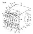
- FIG. 1is a front perspective view of a telecommunications assembly with a plurality of fiber optic modules installed through a front opening.
- FIG. 2is a front perspective of the telecommunications assembly of FIG. 1 , taken from an opposite side.
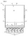
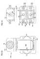
- FIG. 3is a front view of the telecommunications assembly of FIG. 1 .
- FIG. 4is a top view of the telecommunications assembly of FIG. 1 .
- FIG. 5is a rear view of the telecommunications assembly of FIG. 1 .
- FIG. 6is a side view of the telecommunications assembly of FIG. 1 .
- FIG. 7is a front perspective view of the telecommunications assembly of FIG. 1 , with one of the modules exploded out of the assembly and mounting flanges removed from the upper and lower surfaces of the chassis.
- FIG. 8is a rear perspective view of the telecommunications assembly of FIG. 7 .
- FIG. 9is a side view of the telecommunications assembly of FIG. 7 , with a fiber optic adapter holder exploded out of the assembly.
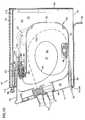
- FIG. 10is a side cross-sectional view of the telecommunications assembly of FIG. 1 , taken through the center of one of the modules mounted within the assembly.
- FIG. 11is a front view of the telecommunications assembly of FIG. 1 , with one of the modules removed to show the adapter holder mounted within the interior of the assembly.
- FIG. 12is a front perspective view of the adapter holder of FIG. 11 , removed from the assembly.
- FIG. 13is a front view of the adapter holder of FIG. 12 .
- FIG. 14is a rear view of the adapter holder of FIG. 12 .
- FIG. 15is a side view of the adapter holder of FIG. 12 .
- FIG. 16is a top view of the adapter holder of FIG. 12 .
- FIG. 17is a front perspective view of an alternative telecommunications assembly according to the present invention, with a plurality of fiber optic splitter modules mounted within a chassis and two modules exploded from their mounted positions.
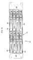
- FIG. 18is a front view of the telecommunications assembly of FIG. 17 .
- FIG. 19is a top view of the telecommunications assembly of FIG. 17 .
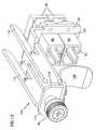
- FIG. 20is a bottom view of the telecommunications assembly of FIG. 17 , with a cable management structure mounted adjacent one side of the chassis.
- FIG. 21is a top view of the telecommunications assembly of FIG. 20 , with a top of the chassis removed.
- FIG. 22is a front perspective view of the telecommunications assembly of FIG. 21 , with one of the modules exploded from its mounting position within the chassis.
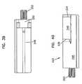
- FIG. 23is a first side view of the telecommunications assembly of FIG. 20 .
- FIG. 24is a second side view of the telecommunications assembly of FIG. 20 .
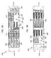
- FIG. 25is a front view of the telecommunications assembly of FIG. 20 with two of the module removed.
- FIG. 26is a rear view of the telecommunications assembly of FIG. 25 .
- FIG. 27is a front view of the chassis of the telecommunications assembly of FIG. 25 , with the modules and adapter assemblies removed from within the chassis.
- FIG. 28is a rear view of the chassis of FIG. 27 .
- FIG. 29is a first side view of the chassis of FIG. 27 .
- FIG. 30is a second side view of the chassis of FIG. 27 .
- FIG. 31is a top view of the chassis of FIG. 27 .
- FIG. 32is a top view of an adapter assembly according to the present invention with extended dust plugs inserted a front end of each adapter and standard duct plugs inserted within a rear end of each adapter.
- FIG. 33is a bottom partially exploded perspective view of the adapter assembly of FIG. 32 .
- FIG. 34is a front view of the adapter assembly of FIG. 32 .
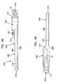
- FIG. 35is a first side view of the adapter assembly of FIG. 32 .
- FIG. 36is a front perspective view of the adapter assembly of FIG. 32 , with the dust plugs removed from the adapters and a shutter partially exploded from its mounting position adjacent one of the adapters.
- FIG. 37is a front view of the adapter assembly of FIG. 36 .
- FIG. 38is a rear view of the adapter assembly of FIG. 36 .
- FIG. 39is a first side view of the adapter assembly of FIG. 36 .
- FIG. 40is a second side view of the adapter assembly of FIG. 36 .
- FIG. 41is a top view of the adapter assembly of FIG. 36 .
- FIG. 42is a bottom view of the adapter assembly of FIG. 36 , with access panels for each adapter of the assembly removed.
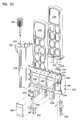
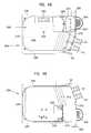
- FIG. 43is a top perspective view of a splitter module according to the present invention for use with the assembly of FIG. 17 .
- FIG. 44is a bottom exploded perspective view of the splitter module of FIG. 43 .
- FIG. 45is a bottom view of the splitter module of FIG. 44 , with the cover removed.
- FIG. 46is a top view of the splitter module of FIG. 43 .
- FIG. 47is a bottom view of the splitter module of FIG. 43 .
- FIG. 48is a first side view of the splitter module of FIG. 43 .
- FIG. 49is a second side view of the splitter module of FIG. 43 .
- FIG. 50is a rear view of the splitter module of FIG. 43 .
- FIG. 51is a front view of the splitter module of FIG. 43 .
- FIG. 1illustrates a telecommunications assembly 10 with mounting locations 12 for mounting a plurality of modules 14 .
- Assembly 10includes a chassis or housing 16 with a first major side 18 , a second major side 20 and a pair of opposing transverse sides 22 extending between the first and second major sides.
- a mounting flange 24may be mounted to each of the major sides extending generally oppositely of each other.
- a secondary or alternative mounting flange 26may also be mounted to one of the major sides to provide options for mounting housing 16 to a particular size or shape of equipment rack, cabinet or other type of installation.
- Housing 16defines a front opening 28 through which modules 14 are inserted within an interior 30 (shown below in FIG. 7 ) of housing 16 .
- Openings 32may be defined in the transverse sides 22 to permit access by a person into interior 30 .
- Openings 32may include a protective pad 34 about a perimeter to provide chafe and other injury to any hands which may pass into or out of interior 30 through one of the openings 32 .
- Visible through opening 32 in FIG. 1is a housing 40 of one of the modules 14 mounted within front opening 28 .
- Flanges 24 and 26may include a plurality of fastener openings 36 for mounting housing 16 where needed in a telecommunications installation.
- each module 14includes a releasably catch 42 adjacent second major side 20 .
- catch 42engages a portion of housing 16 to hold module 14 within front opening 28 and can also be deflected to permit withdrawal of module 14 from housing 16 .
- Each module 14also may include one or more cable exits 44 extending from a front face 46 . Cable exits 44 permit telecommunications cables within module 14 to be directed outside of module 14 , as will be described below with regard to FIG. 10 .
- front faces 46 of modules 14are angled with regard to front opening 28 , which may aid in the direction of cables exiting module 14 toward a desired location in the telecommunications installation. It is anticipated that front faces 46 could be made generally parallel to front edges 38 of transverse sides 22 at front opening 28 within the scope of the present disclosure.
- modules 14includes unequal length flanges 48 and 50 which are received within correspondingly sized slots 52 and 54 , respectively.
- Flange 48 and slot 52are smaller in size than flange 50 and slot 54 .
- Slot 52is sized so that, while flange 48 may be received within slot 52 , larger flange 50 will not fit. This ensures that modules 14 are positioned within front opening 28 in a particular desired orientation. Similar flanges are described in commonly-owned U.S. Pat. No. 5,363,465, the disclosure of which is incorporated herein by reference.
- Opposite latch 42 and mounted to housing 16 at each mounting location 12are an adapter holder 56 releasably held within front opening 28 by a thumbscrew 58 .
- Adapter holder 56is described in further detail below with regard to FIGS. 9 to 16 .
- housing 16further includes a back 60 opposite front opening 28 , substantially closing off the rear of housing 16 . Openings may be provided through back 60 to allow cables or air to pass, but it is anticipated that user access into interior 30 of housing 16 will be made through front opening 28 .
- a lip or finger grip 62may be included to aid removal of module 14 from housing 16 . Finger grip 62 is preferably positioned on module 14 opposite latch 42 so that a user may apply opposing force with fingers or hands to securely grasp the module and remove it from housing 16 .
- latch 42 of module 14includes a recessed area 66 which engages an edge 64 of mounting location 12 to hold module 14 in place within front opening 28 .
- Recessed area 66is formed near a distal end of latch 42 and a flexible portion 68 extends from recessed area 66 to a point of connection to a first side 70 of module 14 .
- Flexible portion 68is resiliently deformable and allows a user to deflect latch 42 to disengage recessed area 66 from edge 64 and remove module 14 from housing 16 or for latch 42 to deflect as module 14 is inserted into front opening 28 and engage edge 64 .
- Module 14includes a second opposing side 72 and a back 78 .
- An intermediate rear face 76is formed in second side 72 by an inset side portion 74 .
- a pair of fiber optic connectors 80is positioned in rear face 76 to mate with fiber optic adapters mounted to adapter holder 56 within interior 30 of housing 16 .
- Module housing 40also includes a first transverse face 82 extending between first side 70 , second side 72 , back 78 and front face 46 .
- a second transverse face 84closes off the opposite side of module housing 40 between front face 46 and back 78 but extends beyond sides 70 and 72 to form flanges 48 and 50 (flange 50 is not visible in FIG. 7 ).
- flange 50is visible as an extension of second transverse face 84 beyond side 70 of module 14 .
- Module housing 40may include curved transitions 86 between sides 70 and 72 and back 78 . Transitions 86 may be shaped to provide bend radius protection to cables within interior 30 as the cables extend to adapters 88 . Alternatively, sides 70 and 72 may terminate directly at back 78 , depending on the needs for placing components within module housing 40 and efficiencies in manufacturing of module housing 40 .
- FIG. 9shows assembly 10 with adapter holder 54 exploded out from interior 30 .
- Holder 54includes an extension 86 to hold and position a pair of adapters 88 to engage connectors 80 of module 14 .
- Each adapter 88includes a first or rear end 90 and a second or front end 92 , and each of the first and second ends are adapted to receive a fiber optic connector which may terminate a fiber optic cable.
- FIG. 10shows a cross-section of assembly 10 with a first cable 94 extending from connector 80 to an optical component 98 , mounted within an interior 96 of module housing 40 .
- Optical component 98may be a splitter or a fan-out or another type of optically significant element.
- First cable 94may be a multi-strand fiber cable with a plurality of strands of optical fiber and optical component 98 may be a fanout to separate the individual strands into each of a plurality of second cables 100 .
- Second cables 100extend from optical component 98 to cable exit 44 .
- first cable 94may be a single fiber whose signal is separated by optical component 98 which is a splitter and a plurality of second cables 100 carrying portions of the signal from first cable 94 may extend to cable exit 44 .
- optical component 98which is a splitter
- second cables 100carrying portions of the signal from first cable 94 may extend to cable exit 44 .
- the arrangement of optical fiber and sheathing at cable exit 44may be as disclosed in commonly-owned U.S. patent application Ser. No. 10/658,802, the disclosure of which is incorporated herein by reference.
- An outside cable 102may extend to rear end 90 of adapter 88 and be terminated by a connector 104 .
- Connector 104may be received in rear end 90 to be optically connected to connector 80 of module 14 .
- Cable 102may extend from interior 30 of housing 16 through an opening in one of sides 18 , 20 , or 22 in housing 16 .
- assembly 10has a module removed from one of the mounting locations 12 and includes an alternative adapter holder 154 in that mounting location 12 .
- Holder 154includes a shield 108 in front of second ends 92 of adapters 88 .
- a housing 16may be installed and a cable 102 led to and connected to first ends 90 of adapters 88 , before a module 14 is placed in the associated mounting location 12 . If cable 102 is illuminated and transmitting light signals, shield 108 will prevent accidental exposure to these signals which might damage eyes or other sensitive organs, or nearby communications equipment.
- holder 154includes an opening 124 through extension 86 through which adapters 88 are mounted.
- Thumbscrew 56extends through a front flange 114 and pair of wall engaging flanges 116 extend backward from adjacent front flange 114 .
- other releasable featuressuch as snap fit devices, quarter turn fasteners, swell latches or similar features may be used in place of thumbscrew 56 on holder 54 or 154 .
- a slot 118Positioned between a forward end of each flange 116 and front flange 114 is a slot 118 .
- Toward a rear end of flanges 116are a pair of wall slots 120 . As shown in FIG.
- an inner wall 110is positioned within interior 30 offset inwardly from first major surface 18 .
- Wall slots 120extend along both sides of inner wall 110 .
- a turned-in forward edge 112 of first major surface 18engages slot 118 .
- extension 86 of holder 154includes a plurality of fastener openings 124 for mounting adapters 88 to extension 86 .
- Fasteners 126may be extended through side flanges 128 of adapter 88 to permit secure mounting of adapters 88 .
- Adapters 88are shown as SC style connectors, although other types, styles and formats of adapters may be used within the scope of the present disclosure and connectors 80 and 104 changed to mate with these alternative adapters.
- Within each of the adapters 88 shownmay be an alignment device, such as a split sleeve 130 to correctly position optical fiber terminated in a ferrule and held by connectors 80 and 104 .
- alignment devices and termination ferrulesare well known in the art.
- Shield 108is curved when viewed from the side, as in FIG. 15 , so that shield 108 will be deflected by module 14 as module 14 is inserted into interior 30 through front opening 28 so that connectors 80 can mate with adapters 88 .
- Shield 108is preferably made of a resilient deformable material that will return to the position shown in FIG. 154 when the module 14 is withdrawn from mounting location 12 .
- Shield 108may be connected to central member 122 by a pair of fasteners such as screws 132 .
- shield 108could be connected to holder 154 by being formed integrally with holder 154 or by spot—welding or other fastening techniques.
- Insertion of module 14 into housing 16 at one of the mounting locations 12may include first unfastening thumbscrew 56 and removing holder 54 or 154 from interior 30 through front opening 28 .
- Cable 102preferably includes enough excess length or slack within interior 30 to permit adapters 88 to be pulled through opening 28 .
- connector 104 of cable 102can be removed from first end 90 of adapter 88 to permit a polished endface of an optical fiber within cable 102 to be cleaned.
- Connector 104can then be reinserted within first end 90 .
- Holder 54 or 154can be reinserted within interior 30 so that the holder engages inner wall 110 and inward turned extension 112 and thumbscrew 56 resecured.
- Insertion of module 14 into front opening 28begins the mating of module 14 to housing 16 and adapters 88 .
- Flanges 48 and 50engage slots 52 and 54 , respectively, as module 14 is inserted.
- Connectors 80 and portions of second side 72engage and deflect shield 108 (if present) as connectors 80 approach second ends 92 of adapters 88 .
- Further insertion of module 14brings connectors 80 into and contact with adapters 88 and the connectors are received within second ends 92 .
- Latch 42is deflected inward as module 14 is inserted and then springs back so that recessed area 66 engages edge 64 .
- Module 14is now mounted within front opening 28 and interior 30 at mounting location 12 and in position to process and transmit signals from cable 102 through first cable 94 , optical component 98 and second cable 100 within module interior 96 .
- an alternative embodiment 200 of a telecommunications assemblyincludes a plurality of fiber optic splitter modules 202 mounted in mounting locations 206 in a front 214 of chassis 204 .
- Chassis 204includes a top 208 , a pair of opposing sides 210 and a pair of mounting flanges extending outward from sides 210 adjacent front 214 .
- Chassis 204also includes a rear 216 .
- Front 214defines a pair vertical stacks of mounting locations 206 which are offset front to rear from each other to provide improved cable pathways for fiber optic cables extending from modules 202 .
- FIGS. 20 to 26illustrate assembly 200 with a cable management structure 220 mounted to one of the mounting flanges 212 and a bottom 218 .
- Two of the modules 202have been removed from mounting locations 206 .
- each module 202includes up to four rear facing connectors 226 which are received within an adapter assembly 222 positioned at each mounting location 206 .
- rear 218 of chassis 204is open for entry of fiber optic cables extending to a rear side of adapter assembly 222 and a rear cable protector is mounted adjacent rear 218 to assist direction of these rear entering cables to adapter assembly 222 .
- Each adapter assembly 222includes up to four fiber optic adapters 232 which are configured to receive one of the rear facing connectors 226 in a front end and connector of a rear entering fiber optic cable in the opposite end.
- each mounting location 206includes a pair of opposing slots 228 when engage flanges 230 extending from sides of modules 202 to positions connectors 226 of modules 202 to engage adapter assembly 222 .
- FIGS. 32 to 35show adapter assembly 222 removed from chassis 204 .
- Adapter assembly 222includes four integrated adapters 232 and each adapter has a rear end 234 and a front end 236 .
- a dust plug 238is positioned in each rear end 234 and an extended dual dust plug 240 is inserted within the front ends of each pair of adapters 232 to seal the interior of adapters 232 from contaminants.
- Adapter assembly 222includes an adapter housing portion 246 within which are located adapters 232 , and a chassis mounting slide 248 which is received within chassis 204 through front end 214 and which cooperates with chassis 204 to define a mounting location 206 .
- a flange 250extends from mounting slide 248 and a thumbscrew 252 for securing adapter assembly 222 within chassis 204 extends through flange 250 .
- Screw 252is positioned within an opening 254 , and is preferably a captive fastener, although other fasteners may be used.
- each adapter 232is positioned within housing portion 246 . Elements of adapter 232 are positioned through an opening 256 into an adapter recess 258 .
- the elements for each adapter 232include a ferrule alignment sleeve 260 and a pair of inner housing halves 262 . These elements are placed within recess 258 in manner similar to that shown in U.S. Pat. No. 5,317,663, issued May 20, 1993, the disclosure of which is incorporated herein by reference.
- a panel 264closes opening 256 and secures the elements within each adapter 232 .
- a shutter 244is positioned within a front opening 266 in front end 236 of each adapter 232 to provide protection against accidental exposure to light. Shutters similar to shutter 244 are described in PCT Publication No. WO 03/093889A1, published on Nov. 12, 2003, the disclosure of which is incorporated herein by reference. Shutter 244 slides into a slot 268 in housing portion 246 . A tab 270 extends from shutter 244 and engages a tab recess 272 to retain shutter 244 in position within each adapter 232 . While shutter 244 is not essential to the function of adapter 232 in connecting fiber optic cables, it is desirable to provide protection against accidental optical signal exposure that could cause injury to workers or other equipment. Preferably, shutter 244 does not engage the ferrule of the connector inserted into each adapter 232 . Instead, the connector housing pushes shutter 244 out of the way.
- FIG. 42illustrates adapter assembly 222 with access panels 264 removed to show elements of each adapter 232 within recesses 258 .
- FIG. 43shows splitter module 202 with side flanges 230 for engaging slots 228 of mounting locations 206 within chassis 204 .
- Connectors 226are mounted to an inset bulkhead 274 positioned between a front 276 and a rear 278 of a module body 280 .
- a screw cover flange 282extends from one of a pair of sides 284 of body 280 and latch 42 extends from the other side 284 .
- Flange 282extends over screw 252 of adapter assembly 222 when module 202 is mounted within chassis 204 . This prevents removal of adapter assembly 222 or loosening of screw 252 when module 202 is mounted at a mounting location 206 .
- Cable exits 44permit passage of optical fibers from within body 280 through front 276 so that the fibers may be extended through cable structure 220 and to other telecommunications equipment.
- module 202includes an interior 286 defined by body 280 and removable bottom plate 288 , which is held to body 280 by a plurality of removable fasteners such as screws 290 .
- a pair of fiber anchors 292mounted within interior 286 adjacent and behind each cable exits 44 .
- module 202preferable houses a splitter which receives a single fiber strand on one end and plurality of fiber strands on the other end.
- Module 202includes up to four rear connectors 226 and so may include up to four splitters (not shown in FIG. 44 ).
- each connector 226may include an angled strain relief boot 227 to provide for redirection of a fiber terminated by connector 226 .
- Connectors 226are access from outside interior 286 through an opening 292 in body 180 .
- a connector mounting block 296spaces and secures connectors 226 for interface with and engagement of adapters 232 of adapter assembly 222 .
- Mounting block 296also includes an upper cable guide 298 for routing cables within interior 286 between connectors 226 and exits 44 .
- a splitter mount 300is also included within interior 286 for positioning and securing one or more optical splitters or other optical components within module 202 .
- a central support post and screw boss 302may also be positioned to provide additional support to bottom plate 288 .
- a finger grip or handle 304extends from front 276 to provide a convenient grip for removing module 202 from chassis 204 , or otherwise assisting in handling.
- module 202includes a full depth portion 306 adjacent front 276 and into which connectors 226 direct incoming fibers, and a partial depth portion 308 beginning adjacent connectors 226 and extending to rear 278 .
- the number of connectors 226 that may be mounted to module 202does not permit sides 184 from being moved toward each other, reducing the width of interior 286 , without encroaching too significantly on cable routing space within interior 286 .
- Having partial depth portion 308 extending from rear 278 to connectors 226permits adapters to be overlapped with body 280 , which is not possible with module 14 , described above.
- the reduced depthdoes reduce the volume of interior 286 but does not adversely impact bend radius requirements within interior 286 .
- a transition 310provides a smooth flow between the depths of portions 306 and 308 .
- a smooth transitionmay be desirable to reduce any sharp angles within interior 286 that fibers may come in contact with, and also may permit easier forming or construction of body 280 .
- connectors 226are positioned within the top vie footprint of body 280 , i.e., between sides 284 , and are also inset from rearmost extension of module 202 , i.e., rear 278 .
- Modules 202are configured so that they can be mounted within chassis 204 from the front without having to access any rear connections, once the adapter assemblies 222 have been positioned and connected to cables. Access to cables and connectors connected to rear end 234 of adapter assemblies 222 may be provided by pulling the assemblies through front 214 of chassis 204 by releasing screw 252 so that these connectors may be accessed for inspection or cleaning.
Landscapes
- Physics & Mathematics (AREA)
- General Physics & Mathematics (AREA)
- Optics & Photonics (AREA)
- Mechanical Coupling Of Light Guides (AREA)
- Light Guides In General And Applications Therefor (AREA)
- Optical Couplings Of Light Guides (AREA)
Abstract
Description
Claims (10)
Priority Applications (1)
| Application Number | Priority Date | Filing Date | Title |
|---|---|---|---|
| US12/757,260US8121457B2 (en) | 2005-05-25 | 2010-04-09 | Fiber optic adapter module |
Applications Claiming Priority (3)
| Application Number | Priority Date | Filing Date | Title |
|---|---|---|---|
| US11/138,889US7376323B2 (en) | 2005-05-25 | 2005-05-25 | Fiber optic adapter module |
| US12/152,840US7706656B2 (en) | 2005-05-25 | 2008-05-15 | Fiber optic adapter module |
| US12/757,260US8121457B2 (en) | 2005-05-25 | 2010-04-09 | Fiber optic adapter module |
Related Parent Applications (1)
| Application Number | Title | Priority Date | Filing Date |
|---|---|---|---|
| US12/152,840ContinuationUS7706656B2 (en) | 2005-05-25 | 2008-05-15 | Fiber optic adapter module |
Publications (2)
| Publication Number | Publication Date |
|---|---|
| US20100310223A1 US20100310223A1 (en) | 2010-12-09 |
| US8121457B2true US8121457B2 (en) | 2012-02-21 |
Family
ID=37011924
Family Applications (3)
| Application Number | Title | Priority Date | Filing Date |
|---|---|---|---|
| US11/138,889Expired - LifetimeUS7376323B2 (en) | 2005-05-25 | 2005-05-25 | Fiber optic adapter module |
| US12/152,840Expired - LifetimeUS7706656B2 (en) | 2005-05-25 | 2008-05-15 | Fiber optic adapter module |
| US12/757,260Expired - Fee RelatedUS8121457B2 (en) | 2005-05-25 | 2010-04-09 | Fiber optic adapter module |
Family Applications Before (2)
| Application Number | Title | Priority Date | Filing Date |
|---|---|---|---|
| US11/138,889Expired - LifetimeUS7376323B2 (en) | 2005-05-25 | 2005-05-25 | Fiber optic adapter module |
| US12/152,840Expired - LifetimeUS7706656B2 (en) | 2005-05-25 | 2008-05-15 | Fiber optic adapter module |
Country Status (10)
| Country | Link |
|---|---|
| US (3) | US7376323B2 (en) |
| EP (1) | EP1883844B1 (en) |
| JP (1) | JP2008542822A (en) |
| KR (1) | KR101234430B1 (en) |
| CN (2) | CN101180561B (en) |
| AU (1) | AU2006249421B2 (en) |
| BR (1) | BRPI0611416B1 (en) |
| MX (1) | MX2007014686A (en) |
| TW (1) | TWI460483B (en) |
| WO (1) | WO2006127397A1 (en) |
Cited By (14)
| Publication number | Priority date | Publication date | Assignee | Title |
|---|---|---|---|---|
| US20180156999A1 (en)* | 2012-05-16 | 2018-06-07 | Corning Optical Communications LLC | High-density port tap fiber optic modules, and related systems and methods for monitoring optical networks |
| US20180157000A1 (en)* | 2015-11-03 | 2018-06-07 | Raycap Intellectual Property Ltd. | Fiber optic cable management system |
| US10031305B2 (en) | 2012-12-19 | 2018-07-24 | CommScope Connectivity Belgium BVBA | Distribution device with incrementally added splitters |
| US10444456B2 (en) | 2008-08-29 | 2019-10-15 | Corning Optical Communications LLC | High density and bandwidth fiber optic apparatuses and related equipment and methods |
| US10606009B2 (en) | 2015-12-01 | 2020-03-31 | CommScope Connectivity Belgium BVBA | Cable distribution system with fan out devices |
| US10606014B2 (en) | 2008-08-29 | 2020-03-31 | Corning Optical Communications LLC | Independently translatable modules and fiber optic equipment trays in fiber optic equipment |
| US10637220B2 (en) | 2016-01-28 | 2020-04-28 | CommScope Connectivity Belgium BVBA | Modular hybrid closure |
| US10732370B2 (en) | 2014-06-17 | 2020-08-04 | CommScope Connectivity Belgium BVBA | Cable distribution system |
| US10812664B2 (en) | 2017-01-20 | 2020-10-20 | Raycap S.A. | Power transmission system for wireless communication systems |
| US10971928B2 (en) | 2018-08-28 | 2021-04-06 | Raycap Ip Assets Ltd | Integrated overvoltage protection and monitoring system |
| US11251608B2 (en) | 2010-07-13 | 2022-02-15 | Raycap S.A. | Overvoltage protection system for wireless communication systems |
| US11294136B2 (en) | 2008-08-29 | 2022-04-05 | Corning Optical Communications LLC | High density and bandwidth fiber optic apparatuses and related equipment and methods |
| US11677164B2 (en) | 2019-09-25 | 2023-06-13 | Raycap Ip Assets Ltd | Hybrid antenna distribution unit |
| US12237134B2 (en) | 2021-12-28 | 2025-02-25 | Raycap Ip Assets Ltd | Circuit protection for hybrid antenna distribution units |
Families Citing this family (163)
| Publication number | Priority date | Publication date | Assignee | Title |
|---|---|---|---|---|
| US5883995A (en) | 1997-05-20 | 1999-03-16 | Adc Telecommunications, Inc. | Fiber connector and adapter |
| US6885798B2 (en) | 2003-09-08 | 2005-04-26 | Adc Telecommunications, Inc. | Fiber optic cable and furcation module |
| US6920274B2 (en)* | 2003-12-23 | 2005-07-19 | Adc Telecommunications, Inc. | High density optical fiber distribution frame with modules |
| US7576997B2 (en)* | 2004-09-20 | 2009-08-18 | Fujitsu Limited | Backplane extension apparatus and method |
| US20060059664A1 (en)* | 2004-09-20 | 2006-03-23 | Sheng Yang S | Button structure |
| US7376322B2 (en) | 2004-11-03 | 2008-05-20 | Adc Telecommunications, Inc. | Fiber optic module and system including rear connectors |
| US7400813B2 (en) | 2005-05-25 | 2008-07-15 | Adc Telecommunications, Inc. | Fiber optic splitter module |
| US7376323B2 (en)* | 2005-05-25 | 2008-05-20 | Adc Telecommunications, Inc. | Fiber optic adapter module |
| US7636507B2 (en)* | 2005-06-17 | 2009-12-22 | Adc Telecommunications, Inc. | Compact blind mateable optical splitter |
| US7346254B2 (en)* | 2005-08-29 | 2008-03-18 | Adc Telecommunications, Inc. | Fiber optic splitter module with connector access |
| US7623749B2 (en) | 2005-08-30 | 2009-11-24 | Adc Telecommunications, Inc. | Fiber distribution hub with modular termination blocks |
| US7330626B2 (en)* | 2005-08-31 | 2008-02-12 | Adc Telecommunications, Inc. | Cabinet including optical bulkhead plate for blown fiber system |
| JP3987078B2 (en)* | 2005-08-31 | 2007-10-03 | 日本電信電話株式会社 | Optical connector |
| US7245809B1 (en)* | 2005-12-28 | 2007-07-17 | Adc Telecommunications, Inc. | Splitter modules for fiber distribution hubs |
| US7418181B2 (en) | 2006-02-13 | 2008-08-26 | Adc Telecommunications, Inc. | Fiber optic splitter module |
| US7816602B2 (en) | 2006-02-13 | 2010-10-19 | Adc Telecommunications, Inc. | Fiber distribution hub with outside accessible grounding terminals |
| US7720343B2 (en) | 2006-02-13 | 2010-05-18 | Adc Telecommunications, Inc. | Fiber distribution hub with swing frame and modular termination panels |
| US7689089B2 (en) | 2006-10-11 | 2010-03-30 | Panduit Corp. | Release latch for pre-terminated cassette |
| US7583885B2 (en)* | 2006-11-28 | 2009-09-01 | Adc Telecommunications, Inc. | Fiber distribution enclosure |
| US7522805B2 (en)* | 2007-03-09 | 2009-04-21 | Adc Telecommunications, Inc. | Wall mount distribution arrangement |
| JP4343238B2 (en)* | 2007-05-29 | 2009-10-14 | 日本航空電子工業株式会社 | Assembly |
| US7391954B1 (en) | 2007-05-30 | 2008-06-24 | Corning Cable Systems Llc | Attenuated optical splitter module |
| US20080298743A1 (en)* | 2007-05-31 | 2008-12-04 | Konstantinos Saravanos | Microsplitter module for optical connectivity |
| US20080298748A1 (en)* | 2007-05-31 | 2008-12-04 | Terry Dean Cox | Direct-connect optical splitter module |
| US7590328B2 (en)* | 2007-08-02 | 2009-09-15 | Adc Telecommunications, Inc. | Fiber termination block with splitters |
| US8798427B2 (en) | 2007-09-05 | 2014-08-05 | Corning Cable Systems Llc | Fiber optic terminal assembly |
| US7885505B2 (en)* | 2007-10-22 | 2011-02-08 | Adc Telecommunications, Inc. | Wavelength division multiplexing module |
| US7720344B2 (en)* | 2007-10-22 | 2010-05-18 | Adc Telecommunications, Inc. | Fiber distribution hub |
| US7536075B2 (en) | 2007-10-22 | 2009-05-19 | Adc Telecommunications, Inc. | Wavelength division multiplexing module |
| US7751672B2 (en) | 2007-10-31 | 2010-07-06 | Adc Telecommunications, Inc. | Low profile fiber distribution hub |
| US8229265B2 (en) | 2007-11-21 | 2012-07-24 | Adc Telecommunications, Inc. | Fiber distribution hub with multiple configurations |
| US8238709B2 (en) | 2007-12-18 | 2012-08-07 | Adc Telecommunications, Inc. | Multi-configuration mounting system for fiber distribution hub |
| US8107816B2 (en) | 2008-01-29 | 2012-01-31 | Adc Telecommunications, Inc. | Wavelength division multiplexing module |
| USD577573S1 (en)* | 2008-03-31 | 2008-09-30 | Ernest James Wood | Fiber optic cable support |
| USD574223S1 (en)* | 2008-03-31 | 2008-08-05 | Ernest James Wood | Fiber optic cable support |
| US8249410B2 (en)* | 2008-04-25 | 2012-08-21 | Corning Cable Systems Llc | Connector housing for a communication network |
| ES2560802T3 (en) | 2008-08-27 | 2016-02-22 | Adc Telecommunications, Inc. | Fiber optic adapter with integrally molded bushing alignment structure |
| US8184938B2 (en) | 2008-08-29 | 2012-05-22 | Corning Cable Systems Llc | Rear-installable fiber optic modules and equipment |
| US7856166B2 (en) | 2008-09-02 | 2010-12-21 | Corning Cable Systems Llc | High-density patch-panel assemblies for optical fiber telecommunications |
| CN102209921B (en) | 2008-10-09 | 2015-11-25 | 康宁光缆系统有限公司 | There is the fibre-optic terminus supported from the adapter panel of the input and output optical fiber of optical splitters |
| US8879882B2 (en) | 2008-10-27 | 2014-11-04 | Corning Cable Systems Llc | Variably configurable and modular local convergence point |
| WO2010059623A1 (en) | 2008-11-21 | 2010-05-27 | Adc Telecommunications, Inc. | Fiber optic telecommunications module |
| CN102282495B (en) | 2009-01-15 | 2015-04-22 | Adc电信公司 | Fiber optic module, chassis and adapter |
| EP2221932B1 (en) | 2009-02-24 | 2011-11-16 | CCS Technology Inc. | Holding device for a cable or an assembly for use with a cable |
| EP2237091A1 (en)* | 2009-03-31 | 2010-10-06 | Corning Cable Systems LLC | Removably mountable fiber optic terminal |
| US8699838B2 (en) | 2009-05-14 | 2014-04-15 | Ccs Technology, Inc. | Fiber optic furcation module |
| US9075216B2 (en) | 2009-05-21 | 2015-07-07 | Corning Cable Systems Llc | Fiber optic housings configured to accommodate fiber optic modules/cassettes and fiber optic panels, and related components and methods |
| US8538226B2 (en) | 2009-05-21 | 2013-09-17 | Corning Cable Systems Llc | Fiber optic equipment guides and rails configured with stopping position(s), and related equipment and methods |
| US8712206B2 (en) | 2009-06-19 | 2014-04-29 | Corning Cable Systems Llc | High-density fiber optic modules and module housings and related equipment |
| AU2010202453A1 (en)* | 2009-06-19 | 2011-01-13 | Corning Cable Systems Llc | Fiber optic module assembly having improved finger access and labeling indicia |
| WO2010148325A1 (en) | 2009-06-19 | 2010-12-23 | Corning Cable Systems Llc | High fiber optic cable packing density apparatus |
| ES2403007A1 (en)* | 2009-07-01 | 2013-05-13 | Adc Telecommunications, Inc | Wall-mounted fiber distribution hub |
| US8606067B2 (en)* | 2009-09-04 | 2013-12-10 | Adc Telecommunications, Inc. | Pedestal terminal with swing frame |
| US8467651B2 (en) | 2009-09-30 | 2013-06-18 | Ccs Technology Inc. | Fiber optic terminals configured to dispose a fiber optic connection panel(s) within an optical fiber perimeter and related methods |
| US9261654B2 (en)* | 2009-10-13 | 2016-02-16 | Leviton Manufacturing Co., Inc. | Fiber optic adapter plates with integrated fiber optic adapters |
| US20110129185A1 (en)* | 2009-11-30 | 2011-06-02 | Lewallen C Paul | Articulated Strain Relief Boot on a Fiber Optic Module and Associated Methods |
| US8625950B2 (en) | 2009-12-18 | 2014-01-07 | Corning Cable Systems Llc | Rotary locking apparatus for fiber optic equipment trays and related methods |
| US8824850B2 (en)* | 2010-01-26 | 2014-09-02 | Adc Telecommunications, Inc. | Insect-infestation prevention device for a telecommunications equipment housing |
| US8992099B2 (en) | 2010-02-04 | 2015-03-31 | Corning Cable Systems Llc | Optical interface cards, assemblies, and related methods, suited for installation and use in antenna system equipment |
| CN102870021B (en) | 2010-03-02 | 2015-03-11 | 蒂安电子服务有限责任公司 | Fibre-optic telecommunication module |
| US9547144B2 (en) | 2010-03-16 | 2017-01-17 | Corning Optical Communications LLC | Fiber optic distribution network for multiple dwelling units |
| US8913866B2 (en) | 2010-03-26 | 2014-12-16 | Corning Cable Systems Llc | Movable adapter panel |
| US8792767B2 (en) | 2010-04-16 | 2014-07-29 | Ccs Technology, Inc. | Distribution device |
| CA2796221C (en) | 2010-04-16 | 2018-02-13 | Ccs Technology, Inc. | Sealing and strain relief device for data cables |
| EP2381284B1 (en) | 2010-04-23 | 2014-12-31 | CCS Technology Inc. | Under floor fiber optic distribution device |
| US9239442B2 (en) | 2010-04-27 | 2016-01-19 | Adc Communications (Shanghai) Co., Ltd. | Fiber optic module and chassis |
| US8879881B2 (en) | 2010-04-30 | 2014-11-04 | Corning Cable Systems Llc | Rotatable routing guide and assembly |
| US8660397B2 (en) | 2010-04-30 | 2014-02-25 | Corning Cable Systems Llc | Multi-layer module |
| US8705926B2 (en) | 2010-04-30 | 2014-04-22 | Corning Optical Communications LLC | Fiber optic housings having a removable top, and related components and methods |
| US9075217B2 (en) | 2010-04-30 | 2015-07-07 | Corning Cable Systems Llc | Apparatuses and related components and methods for expanding capacity of fiber optic housings |
| US9720195B2 (en) | 2010-04-30 | 2017-08-01 | Corning Optical Communications LLC | Apparatuses and related components and methods for attachment and release of fiber optic housings to and from an equipment rack |
| US9519118B2 (en) | 2010-04-30 | 2016-12-13 | Corning Optical Communications LLC | Removable fiber management sections for fiber optic housings, and related components and methods |
| US9632270B2 (en) | 2010-04-30 | 2017-04-25 | Corning Optical Communications LLC | Fiber optic housings configured for tool-less assembly, and related components and methods |
| US8718436B2 (en) | 2010-08-30 | 2014-05-06 | Corning Cable Systems Llc | Methods, apparatuses for providing secure fiber optic connections |
| WO2012054454A2 (en) | 2010-10-19 | 2012-04-26 | Corning Cable Systems Llc | Transition box for multiple dwelling unit fiber optic distribution network |
| US9279951B2 (en) | 2010-10-27 | 2016-03-08 | Corning Cable Systems Llc | Fiber optic module for limited space applications having a partially sealed module sub-assembly |
| US9116324B2 (en) | 2010-10-29 | 2015-08-25 | Corning Cable Systems Llc | Stacked fiber optic modules and fiber optic equipment configured to support stacked fiber optic modules |
| US8662760B2 (en) | 2010-10-29 | 2014-03-04 | Corning Cable Systems Llc | Fiber optic connector employing optical fiber guide member |
| CA2819235C (en) | 2010-11-30 | 2018-01-16 | Corning Cable Systems Llc | Fiber device holder and strain relief device |
| WO2012106510A2 (en) | 2011-02-02 | 2012-08-09 | Corning Cable Systems Llc | Dense fiber optic connector assemblies and related connectors and cables suitable for establishing optical connections for optical backplanes in equipment racks |
| US8861919B2 (en) | 2011-02-16 | 2014-10-14 | Tyco Electronics Corporation | Fiber optic closure |
| US9182563B2 (en) | 2011-03-31 | 2015-11-10 | Adc Telecommunications, Inc. | Adapter plate for fiber optic module |
| US9008485B2 (en) | 2011-05-09 | 2015-04-14 | Corning Cable Systems Llc | Attachment mechanisms employed to attach a rear housing section to a fiber optic housing, and related assemblies and methods |
| AU2012275598A1 (en) | 2011-06-30 | 2014-01-16 | Corning Optical Communications LLC | Fiber optic equipment assemblies employing non-U-width-sized housings and related methods |
| US8953924B2 (en) | 2011-09-02 | 2015-02-10 | Corning Cable Systems Llc | Removable strain relief brackets for securing fiber optic cables and/or optical fibers to fiber optic equipment, and related assemblies and methods |
| WO2013033890A1 (en) | 2011-09-06 | 2013-03-14 | Adc Telecommunications, Inc. | Adapter for fiber optic module |
| US9417418B2 (en) | 2011-09-12 | 2016-08-16 | Commscope Technologies Llc | Flexible lensed optical interconnect device for signal distribution |
| US9229172B2 (en) | 2011-09-12 | 2016-01-05 | Commscope Technologies Llc | Bend-limited flexible optical interconnect device for signal distribution |
| US8770861B2 (en) | 2011-09-27 | 2014-07-08 | Tyco Electronics Corporation | Outside plant termination enclosure |
| RU2611105C2 (en) | 2011-10-07 | 2017-02-21 | Адс Телекоммьюникейшнз, Инк. | Fibre-optic cartridge, system and method |
| CN103975264B (en) | 2011-10-07 | 2015-09-16 | Adc电信公司 | Slidable fiber optic connection module with cable slack management |
| US9170391B2 (en) | 2011-10-07 | 2015-10-27 | Adc Telecommunications, Inc. | Slidable fiber optic connection module with cable slack management |
| US9002166B2 (en) | 2011-10-07 | 2015-04-07 | Adc Telecommunications, Inc. | Slidable fiber optic connection module with cable slack management |
| US8731364B2 (en)* | 2011-11-21 | 2014-05-20 | Ortronics, Inc. | Breakout assemblies and associated mounting members for fiber optic applications |
| US9038832B2 (en) | 2011-11-30 | 2015-05-26 | Corning Cable Systems Llc | Adapter panel support assembly |
| US9219546B2 (en) | 2011-12-12 | 2015-12-22 | Corning Optical Communications LLC | Extremely high frequency (EHF) distributed antenna systems, and related components and methods |
| US9075203B2 (en) | 2012-01-17 | 2015-07-07 | Adc Telecommunications, Inc. | Fiber optic adapter block |
| US10110307B2 (en) | 2012-03-02 | 2018-10-23 | Corning Optical Communications LLC | Optical network units (ONUs) for high bandwidth connectivity, and related components and methods |
| US9004778B2 (en) | 2012-06-29 | 2015-04-14 | Corning Cable Systems Llc | Indexable optical fiber connectors and optical fiber connector arrays |
| US9250409B2 (en) | 2012-07-02 | 2016-02-02 | Corning Cable Systems Llc | Fiber-optic-module trays and drawers for fiber-optic equipment |
| US9049500B2 (en) | 2012-08-31 | 2015-06-02 | Corning Cable Systems Llc | Fiber optic terminals, systems, and methods for network service management |
| US9042702B2 (en) | 2012-09-18 | 2015-05-26 | Corning Cable Systems Llc | Platforms and systems for fiber optic cable attachment |
| US9195021B2 (en)* | 2012-09-21 | 2015-11-24 | Adc Telecommunications, Inc. | Slidable fiber optic connection module with cable slack management |
| US10082636B2 (en) | 2012-09-21 | 2018-09-25 | Commscope Technologies Llc | Slidable fiber optic connection module with cable slack management |
| US9146362B2 (en) | 2012-09-21 | 2015-09-29 | Adc Telecommunications, Inc. | Insertion and removal tool for a fiber optic ferrule alignment sleeve |
| US9146374B2 (en) | 2012-09-28 | 2015-09-29 | Adc Telecommunications, Inc. | Rapid deployment packaging for optical fiber |
| NZ706687A (en) | 2012-09-28 | 2017-09-29 | Adc Telecommunications Inc | Fiber optic cassette |
| US9753229B2 (en) | 2012-09-28 | 2017-09-05 | Commscope Connectivity Uk Limited | Manufacture and testing of fiber optic cassette |
| US9223094B2 (en) | 2012-10-05 | 2015-12-29 | Tyco Electronics Nederland Bv | Flexible optical circuit, cassettes, and methods |
| US8909019B2 (en) | 2012-10-11 | 2014-12-09 | Ccs Technology, Inc. | System comprising a plurality of distribution devices and distribution device |
| ES2551077T3 (en) | 2012-10-26 | 2015-11-16 | Ccs Technology, Inc. | Fiber optic management unit and fiber optic distribution device |
| CN105074525A (en) | 2013-01-29 | 2015-11-18 | 泰科电子瑞侃有限公司 | Fiber Distribution System |
| US9128262B2 (en) | 2013-02-05 | 2015-09-08 | Adc Telecommunications, Inc. | Slidable telecommunications tray with cable slack management |
| WO2014133943A1 (en) | 2013-02-27 | 2014-09-04 | Adc Telecommunications, Inc. | Slidable fiber optic connection module with cable slack management |
| US8985862B2 (en) | 2013-02-28 | 2015-03-24 | Corning Cable Systems Llc | High-density multi-fiber adapter housings |
| US9423579B2 (en)* | 2013-03-05 | 2016-08-23 | Finisar Corporation | Latch mechanism for communication module |
| US9435975B2 (en) | 2013-03-15 | 2016-09-06 | Commscope Technologies Llc | Modular high density telecommunications frame and chassis system |
| US9535226B2 (en)* | 2013-03-29 | 2017-01-03 | 3M Innovative Properties Company | Modular breakout device for optical and electrical connections |
| AP2015008820A0 (en) | 2013-04-24 | 2015-10-31 | Adc Czech Republic Sro | Optical fiber distribution system |
| EP2989496B1 (en) | 2013-04-24 | 2019-06-12 | CommScope Connectivity Belgium BVBA | Universal mounting mechanism for mounting a telecommunications chassis to a telecommunications fixture |
| WO2015126472A2 (en) | 2013-11-11 | 2015-08-27 | Adc Telecommunications, Inc. | Telecommunications module |
| WO2015116672A1 (en) | 2014-01-28 | 2015-08-06 | Adc Telecommunications, Inc. | Slidable fiber optic connection module with cable slack management |
| US9494758B2 (en) | 2014-04-03 | 2016-11-15 | Commscope Technologies Llc | Fiber optic distribution system |
| WO2015200321A1 (en) | 2014-06-23 | 2015-12-30 | Adc Telecommunications, Inc. | Fiber cable fan-out assembly and method |
| US10054753B2 (en) | 2014-10-27 | 2018-08-21 | Commscope Technologies Llc | Fiber optic cable with flexible conduit |
| WO2016094331A1 (en) | 2014-12-10 | 2016-06-16 | Commscope Technologies Llc | Fiber optic cable slack management module |
| AU2016239875C1 (en) | 2015-04-03 | 2021-06-24 | CommScope Connectivity Belgium BVBA | Telecommunications distribution elements |
| MX2017014377A (en) | 2015-05-15 | 2018-08-15 | Adc Telecommunications Shanghai Distrib Co Ltd | Alignment sleeve assembly and optical fibre adapter. |
| AU2015207954C1 (en) | 2015-07-31 | 2022-05-05 | Adc Communications (Australia) Pty Limited | Cable breakout assembly |
| WO2017034931A1 (en) | 2015-08-21 | 2017-03-02 | Commscope Technologies Llc | Telecommunications module |
| EP3389560A1 (en) | 2015-12-15 | 2018-10-24 | The University of Rochester | Refractive corrector incorporating a continuous central phase zone and peripheral phase discontinuities |
| JP2017134118A (en) | 2016-01-25 | 2017-08-03 | 富士通株式会社 | Optical adapter |
| EP3403125B1 (en) | 2016-03-18 | 2021-07-14 | Commscope Technologies LLC | Fiber-optic cable fanout conduit arrangement and method for organizing optical fibers |
| US10222571B2 (en) | 2016-04-07 | 2019-03-05 | Commscope Technologies Llc | Telecommunications module and frame |
| WO2017184501A1 (en) | 2016-04-19 | 2017-10-26 | Commscope, Inc. Of North Carolina | Door assembly for a telecommunications chassis with a combination hinge structure |
| ES2851948T3 (en) | 2016-04-19 | 2021-09-09 | Commscope Inc North Carolina | Telecom rack with slide out trays |
| US10890730B2 (en) | 2016-08-31 | 2021-01-12 | Commscope Technologies Llc | Fiber optic cable clamp and clamp assembly |
| WO2018046677A1 (en) | 2016-09-08 | 2018-03-15 | CommScope Connectivity Belgium BVBA | Telecommunications distribution elements |
| US9778432B1 (en) | 2016-09-16 | 2017-10-03 | All Systems Broadband, Inc. | Fiber optic cassette with mounting wall compatible latch |
| US10914909B2 (en) | 2016-10-13 | 2021-02-09 | Commscope Technologies Llc | Fiber optic breakout transition assembly incorporating epoxy plug and cable strain relief |
| IT201600126393A1 (en)* | 2016-12-14 | 2018-06-14 | Btg Italia S P A | MODULE FOR THE MANAGEMENT OF OPTICAL FIBERS |
| CN110622051A (en) | 2017-05-08 | 2019-12-27 | 康普技术有限责任公司 | Optical fiber branch transition assembly |
| WO2018226959A1 (en) | 2017-06-07 | 2018-12-13 | Commscope Technologies Llc | Fiber optic adapter and cassette |
| CN208297782U (en)* | 2017-08-25 | 2018-12-28 | 光联通讯有限公司 | Fiber plant |
| JP7177147B2 (en)* | 2017-09-20 | 2022-11-22 | モレックス エルエルシー | Light blocking shutter for fiber optic adapter |
| US11409068B2 (en) | 2017-10-02 | 2022-08-09 | Commscope Technologies Llc | Fiber optic circuit and preparation method |
| US11385429B2 (en) | 2017-10-18 | 2022-07-12 | Commscope Technologies Llc | Fiber optic connection cassette |
| US10470333B2 (en)* | 2018-01-05 | 2019-11-05 | Quanta Computer Inc. | Flexible chassis for different sized sleds |
| US11852882B2 (en) | 2018-02-28 | 2023-12-26 | Commscope Technologies Llc | Packaging assembly for telecommunications equipment |
| US10416406B1 (en) | 2018-03-01 | 2019-09-17 | Afl Telecommunications Llc | Communications module housing |
| WO2019204317A1 (en) | 2018-04-16 | 2019-10-24 | Commscope Technologies Llc | Adapter structure |
| US11635578B2 (en) | 2018-04-17 | 2023-04-25 | CommScope Connectivity Belgium BVBA | Telecommunications distribution elements |
| EP3844547A1 (en) | 2018-08-31 | 2021-07-07 | CommScope Connectivity Belgium BVBA | Frame assemblies for optical fiber distribution elements |
| PL3844973T3 (en) | 2018-08-31 | 2025-03-03 | CommScope Connectivity Belgium BVBA | Frame assemblies for optical fiber distribution elements |
| EP3845044B1 (en) | 2018-08-31 | 2023-02-15 | CommScope Connectivity Belgium BVBA | Frame assemblies for optical fiber distribution elements |
| EP3844546A1 (en) | 2018-08-31 | 2021-07-07 | CommScope Connectivity Belgium BVBA | Frame assemblies for optical fiber distribution elements |
| WO2020043914A1 (en) | 2018-08-31 | 2020-03-05 | CommScope Connectivity Belgium BVBA | Frame assemblies for optical fiber distribution elements |
| WO2020084012A1 (en) | 2018-10-23 | 2020-04-30 | CommScope Connectivity Belgium BVBA | Frame assemblies for optical fiber distribution elements |
| US10451828B1 (en) | 2018-11-09 | 2019-10-22 | Afl Telecommunications Llc | Communications module housing |
| EP3914947A1 (en) | 2019-01-25 | 2021-12-01 | CommScope Connectivity Belgium BVBA | Frame assemblies for optical fiber distribution elements |
| WO2021148544A1 (en) | 2020-01-22 | 2021-07-29 | CommScope Connectivity Belgium BVBA | Cable termination units for optical fiber distribution elements |
| US12099246B2 (en) | 2020-01-24 | 2024-09-24 | CommScope Connectivity Belgium BVBA | Telecommunications distribution elements |
| US12339511B2 (en) | 2020-03-31 | 2025-06-24 | Commscope Technologies Llc | Fiber optic cable management systems and methods |
Citations (65)
| Publication number | Priority date | Publication date | Assignee | Title |
|---|---|---|---|---|
| US5189410A (en) | 1989-12-28 | 1993-02-23 | Fujitsu Limited | Digital cross connect system |
| DE4130706A1 (en) | 1991-09-14 | 1993-03-18 | Standard Elektrik Lorenz Ag | Optical jack-plug incorporating optical coupler - has optical fibre inserted in capillary provided by jack-plug pin and divergent optical paths coupled to rear optical fibres |
| US5317663A (en)* | 1993-05-20 | 1994-05-31 | Adc Telecommunications, Inc. | One-piece SC adapter |
| US5339379A (en) | 1993-06-18 | 1994-08-16 | Telect, Inc. | Telecommunication fiber optic cable distribution apparatus |
| US5363465A (en) | 1993-02-19 | 1994-11-08 | Adc Telecommunications, Inc. | Fiber optic connector module |
| US5432875A (en) | 1993-02-19 | 1995-07-11 | Adc Telecommunications, Inc. | Fiber optic monitor module |
| US5497444A (en) | 1994-01-21 | 1996-03-05 | Adc Telecommunications, Inc. | High-density fiber distribution frame |
| EP0730177A2 (en) | 1995-02-28 | 1996-09-04 | AT&T Corp. | Patch panel and collar for optical fiber couplers |
| US5613030A (en) | 1995-05-15 | 1997-03-18 | The Whitaker Corporation | High density fiber optic interconnection enclosure |
| US5627925A (en) | 1995-04-07 | 1997-05-06 | Lucent Technologies Inc. | Non-blocking optical cross-connect structure for telecommunications network |
| US5694511A (en) | 1996-09-09 | 1997-12-02 | Lucent Technologies Inc. | Optical switching apparatus and method for use in the construction mode testing of a modular fiber administration system |
| US5701380A (en) | 1996-06-24 | 1997-12-23 | Telect, Inc. | Fiber optic module for high density supply of patching and splicing |
| EP0828356A2 (en) | 1996-09-09 | 1998-03-11 | Lucent Technologies Inc. | Optical monitoring and test access interconnection module |
| US5946440A (en) | 1997-11-17 | 1999-08-31 | Adc Telecommunications, Inc. | Optical fiber cable management device |
| WO2000075706A2 (en) | 1999-06-03 | 2000-12-14 | Adc Telecommunications, Inc. | Optical fiber distribution frame with connector modules |
| US6208796B1 (en) | 1998-07-21 | 2001-03-27 | Adc Telecommunications, Inc. | Fiber optic module |
| EP1092996A2 (en) | 1999-10-15 | 2001-04-18 | Tyco Electronics Corporation | Fiberoptical device having an integral array interface |
| US6226111B1 (en) | 1996-12-06 | 2001-05-01 | Telcordia Technologies, Inc. | Inter-ring cross-connect for survivable multi-wavelength optical communication networks |
| EP1107031A1 (en) | 1999-12-07 | 2001-06-13 | Molex Incorporated | Alignment system for mating connectors |
| US6263136B1 (en) | 1999-10-29 | 2001-07-17 | Lucent Technologies | Intelligent optical transmitter module |
| EP1179745A2 (en) | 2000-08-10 | 2002-02-13 | F.C.I. - Framatome Connectors International | Optical connector adapter |
| US6363183B1 (en) | 2000-01-04 | 2002-03-26 | Seungug Koh | Reconfigurable and scalable intergrated optic waveguide add/drop multiplexing element using micro-opto-electro-mechanical systems and methods of fabricating thereof |
| US6370294B1 (en) | 1999-06-25 | 2002-04-09 | Adc Telecommunications, Inc. | Fiber optic circuit and module with switch |
| DE20201170U1 (en) | 2002-01-15 | 2002-05-29 | Infineon Technologies AG, 81669 München | Device for protecting the plug receptacle of an opto-electronic component |
| US6418262B1 (en) | 2000-03-13 | 2002-07-09 | Adc Telecommunications, Inc. | Fiber distribution frame with fiber termination blocks |
| US6424781B1 (en) | 1999-03-01 | 2002-07-23 | Adc Telecommunications, Inc. | Optical fiber distribution frame with pivoting connector panels |
| US20020181896A1 (en) | 2001-06-04 | 2002-12-05 | Mcclellan Brian J. | Telecommunications chassis and module |
| WO2002099528A1 (en) | 2001-06-01 | 2002-12-12 | Stratos Lightwave, Inc. | 'modular wavelength division multiplexing (wdm) connector' |
| WO2002103429A2 (en) | 2000-11-20 | 2002-12-27 | Adc Telecommunications, Inc. | Optical fiber distribution frame with outside plant enclosure |
| US20030031423A1 (en) | 2001-04-11 | 2003-02-13 | Adc Telecommunications, Inc. | Fiber optic adapter with attenuator and method |
| US6532332B2 (en) | 2001-02-15 | 2003-03-11 | Adc Telecommunications, Inc. | Cable guide for fiber termination block |
| US6535682B1 (en) | 1999-03-01 | 2003-03-18 | Adc Telecommunications, Inc. | Optical fiber distribution frame with connector modules |
| US6579014B2 (en) | 2001-09-28 | 2003-06-17 | Corning Cable Systems Llc | Fiber optic receptacle |
| US6591051B2 (en) | 2001-11-16 | 2003-07-08 | Adc Telecommunications, Inc. | Fiber termination block with angled slide |
| US20030134541A1 (en) | 2001-04-13 | 2003-07-17 | Adc Telecommunications, Inc. | DSX jack including sliding rear connector |
| US20030132685A1 (en) | 2000-12-22 | 2003-07-17 | Guy Sucharczuk | Chassis with repositionable plates |
| US20030147597A1 (en)* | 2002-02-07 | 2003-08-07 | Jaime Duran | Cantilevered shutter for optical adapter |
| US6614953B2 (en) | 2001-03-16 | 2003-09-02 | Photuris, Inc. | Modular all-optical cross-connect |
| US20030169974A1 (en) | 2002-03-05 | 2003-09-11 | Ngo Hung Viet | Optical connector adapter with latch inserts |
| US20030185535A1 (en) | 2002-03-27 | 2003-10-02 | Thomas Tinucci | Termination panel with pivoting bulkhead and cable management |
| US20030202765A1 (en) | 2002-04-24 | 2003-10-30 | Franklin Michael J. | Cable management panel with sliding drawer |
| US6647197B1 (en) | 2000-06-02 | 2003-11-11 | Panduit Corp. | Modular latch and guide rail arrangement for use in fiber optic cable management systems |
| WO2003093889A1 (en) | 2002-05-03 | 2003-11-13 | Krone Gmbh | Coupling for glass fiber connectors with retrofittable security valve |
| US6668108B1 (en) | 2000-06-02 | 2003-12-23 | Calient Networks, Inc. | Optical cross-connect switch with integrated optical signal tap |
| US6810193B1 (en) | 1999-11-22 | 2004-10-26 | Ccs Technology, Inc. | Cassette for receiving optical waveguides with overlengths and fiber splices |
| EP1473578A2 (en) | 2003-05-02 | 2004-11-03 | Panduit Corporation | Fiber optic connector removal tool |
| US20040240826A1 (en) | 2003-05-30 | 2004-12-02 | Lucent Technologies Inc. | Optical fiber connection system |
| US20050002633A1 (en) | 2003-07-02 | 2005-01-06 | Solheid James J. | Telecommunications connection cabinet |
| US20050053341A1 (en) | 2003-09-08 | 2005-03-10 | Zimmel Steven C. | Fiber optic cable and furcation module |
| US20050067847A1 (en) | 2003-09-29 | 2005-03-31 | Zellak Darren James | Connector coupling/decoupling tool |
| US20050105879A1 (en) | 2002-11-29 | 2005-05-19 | Katsumi Kanasaki | Unit installed in electronic equipment and connection mechanism of transmission line of the electronic equipment |
| US20050105873A1 (en) | 2003-11-17 | 2005-05-19 | Fiber Optic Network Solutions Corporation | Systems and methods for managing optical fibers and components within an enclosure in an optical communications networks |
| US20050108579A1 (en)* | 2002-02-01 | 2005-05-19 | Novell, Inc. | Isolating multiple authentication channels, each using multiple authentication models |
| US20050232550A1 (en) | 2002-09-06 | 2005-10-20 | Masahiro Nakajima | Optical connector plug, optical connector adapter and optical connector |
| US20050232565A1 (en) | 2004-04-16 | 2005-10-20 | Ross Heggestad | Normal through optical panel |
| US20050232551A1 (en) | 2004-04-16 | 2005-10-20 | Cheng-Pei Chang | Devices for preventing lens contamination in optoelectronic modules and connectors |
| US20050281526A1 (en) | 2004-06-18 | 2005-12-22 | Soutsada Vongseng | Multi-position fiber optic connector holder and method |
| US20060093301A1 (en) | 2004-11-03 | 2006-05-04 | Zimmel Steven C | Fiber optic module and system including rear connectors |
| US7142764B2 (en) | 2003-03-20 | 2006-11-28 | Tyco Electronics Corporation | Optical fiber interconnect cabinets, termination modules and fiber connectivity management for the same |
| US20060269205A1 (en) | 2005-05-25 | 2006-11-30 | Zimmel Steven C | Fiber optic splitter module |
| US20060285807A1 (en) | 2005-06-17 | 2006-12-21 | Yu Lu | Compact blind mateable optical splitter |
| US20070047893A1 (en) | 2005-08-29 | 2007-03-01 | Anne Kramer | Fiber optic splitter module with connector access |
| US7194181B2 (en) | 2005-03-31 | 2007-03-20 | Adc Telecommunications, Inc. | Adapter block including connector storage |
| US20070147765A1 (en) | 2005-12-28 | 2007-06-28 | Jeff Gniadek | Splitter modules for fiber distribution hubs |
| US7376323B2 (en) | 2005-05-25 | 2008-05-20 | Adc Telecommunications, Inc. | Fiber optic adapter module |
Family Cites Families (13)
| Publication number | Priority date | Publication date | Assignee | Title |
|---|---|---|---|---|
| US885798A (en)* | 1905-12-22 | 1908-04-28 | Albert P Smith | Balanced pump. |
| US5445738A (en)* | 1993-08-19 | 1995-08-29 | Fry; Darrel D. | Vibrating filter |
| FR2762467B1 (en)* | 1997-04-16 | 1999-07-02 | France Telecom | MULTI-CHANNEL ACOUSTIC ECHO CANCELING METHOD AND MULTI-CHANNEL ACOUSTIC ECHO CANCELER |
| JPH1164647A (en)* | 1997-08-12 | 1999-03-05 | Nec Corp | Optical package and cabinet for electronic device |
| US6347888B1 (en)* | 1998-11-23 | 2002-02-19 | Adc Telecommunications, Inc. | Fiber optic adapter, including hybrid connector system |
| JP2001356219A (en)* | 2000-06-15 | 2001-12-26 | Kawamura Electric Inc | Optical adapter fixture |
| JP2002098860A (en)* | 2000-07-12 | 2002-04-05 | Molex Inc | Alignment device for optical connectors |
| JP2002116350A (en)* | 2000-10-05 | 2002-04-19 | Hirose Electric Co Ltd | Adaptor or receptacle for optical cable |
| JP2002230794A (en)* | 2001-02-05 | 2002-08-16 | Funai Electric Co Ltd | Optical disk device |
| US6568861B2 (en)* | 2001-05-16 | 2003-05-27 | Fci Americas Technology, Inc. | Fiber optic adapter |
| US20020171896A1 (en)* | 2001-05-21 | 2002-11-21 | Lightpointe Communications, Inc. | Free-space optical communication system employing wavelength conversion |
| WO2004008214A1 (en)* | 2002-07-15 | 2004-01-22 | Tomoegawa Paper Co., Ltd. | Component for connecting optical fibers, optical fiber connection structure, and optical fiber connecting method |
| JP4419470B2 (en)* | 2003-08-15 | 2010-02-24 | 富士通株式会社 | Optical fiber cable wiring accommodation structure, optical connector accommodation method, and optical connector connection method |
- 2005
- 2005-05-25USUS11/138,889patent/US7376323B2/ennot_activeExpired - Lifetime
- 2006
- 2006-05-18AUAU2006249421Apatent/AU2006249421B2/ennot_activeCeased
- 2006-05-18MXMX2007014686Apatent/MX2007014686A/enactiveIP Right Grant
- 2006-05-18CNCN2006800178652Apatent/CN101180561B/ennot_activeExpired - Fee Related
- 2006-05-18BRBRPI0611416Apatent/BRPI0611416B1/ennot_activeIP Right Cessation
- 2006-05-18CNCN2010101244626Apatent/CN101846774B/ennot_activeExpired - Fee Related
- 2006-05-18KRKR1020077030394Apatent/KR101234430B1/ennot_activeExpired - Fee Related
- 2006-05-18WOPCT/US2006/019278patent/WO2006127397A1/enactiveApplication Filing
- 2006-05-18JPJP2008513549Apatent/JP2008542822A/ennot_activeCeased
- 2006-05-18EPEP06770583.0Apatent/EP1883844B1/ennot_activeNot-in-force
- 2006-05-25TWTW095118622Apatent/TWI460483B/ennot_activeIP Right Cessation
- 2008
- 2008-05-15USUS12/152,840patent/US7706656B2/ennot_activeExpired - Lifetime
- 2010
- 2010-04-09USUS12/757,260patent/US8121457B2/ennot_activeExpired - Fee Related
Patent Citations (74)
| Publication number | Priority date | Publication date | Assignee | Title |
|---|---|---|---|---|
| US5189410A (en) | 1989-12-28 | 1993-02-23 | Fujitsu Limited | Digital cross connect system |
| DE4130706A1 (en) | 1991-09-14 | 1993-03-18 | Standard Elektrik Lorenz Ag | Optical jack-plug incorporating optical coupler - has optical fibre inserted in capillary provided by jack-plug pin and divergent optical paths coupled to rear optical fibres |
| US5363465A (en) | 1993-02-19 | 1994-11-08 | Adc Telecommunications, Inc. | Fiber optic connector module |
| US5432875A (en) | 1993-02-19 | 1995-07-11 | Adc Telecommunications, Inc. | Fiber optic monitor module |
| US5317663A (en)* | 1993-05-20 | 1994-05-31 | Adc Telecommunications, Inc. | One-piece SC adapter |
| US5339379A (en) | 1993-06-18 | 1994-08-16 | Telect, Inc. | Telecommunication fiber optic cable distribution apparatus |
| US5717810A (en) | 1994-01-21 | 1998-02-10 | Adc Telecommunications, Inc. | High-density fiber distribution frame |
| USRE38311E1 (en) | 1994-01-21 | 2003-11-11 | Adc Telecommunications, Inc. | High-density cable distribution frame |
| US5497444A (en) | 1994-01-21 | 1996-03-05 | Adc Telecommunications, Inc. | High-density fiber distribution frame |
| EP0730177A2 (en) | 1995-02-28 | 1996-09-04 | AT&T Corp. | Patch panel and collar for optical fiber couplers |
| US5627925A (en) | 1995-04-07 | 1997-05-06 | Lucent Technologies Inc. | Non-blocking optical cross-connect structure for telecommunications network |
| US5613030A (en) | 1995-05-15 | 1997-03-18 | The Whitaker Corporation | High density fiber optic interconnection enclosure |
| US5701380A (en) | 1996-06-24 | 1997-12-23 | Telect, Inc. | Fiber optic module for high density supply of patching and splicing |
| US5694511A (en) | 1996-09-09 | 1997-12-02 | Lucent Technologies Inc. | Optical switching apparatus and method for use in the construction mode testing of a modular fiber administration system |
| EP0828356A2 (en) | 1996-09-09 | 1998-03-11 | Lucent Technologies Inc. | Optical monitoring and test access interconnection module |
| US6226111B1 (en) | 1996-12-06 | 2001-05-01 | Telcordia Technologies, Inc. | Inter-ring cross-connect for survivable multi-wavelength optical communication networks |
| US5946440A (en) | 1997-11-17 | 1999-08-31 | Adc Telecommunications, Inc. | Optical fiber cable management device |
| US6208796B1 (en) | 1998-07-21 | 2001-03-27 | Adc Telecommunications, Inc. | Fiber optic module |
| US6307998B2 (en) | 1998-07-21 | 2001-10-23 | Adc Telecommunications, Inc. | Fiber optic module including lens cap |
| US6424781B1 (en) | 1999-03-01 | 2002-07-23 | Adc Telecommunications, Inc. | Optical fiber distribution frame with pivoting connector panels |
| US6760531B1 (en) | 1999-03-01 | 2004-07-06 | Adc Telecommunications, Inc. | Optical fiber distribution frame with outside plant enclosure |
| US6556763B1 (en) | 1999-03-01 | 2003-04-29 | Adc Telecommunications, Inc. | Optical fiber distribution frame with connector modules |
| US6535682B1 (en) | 1999-03-01 | 2003-03-18 | Adc Telecommunications, Inc. | Optical fiber distribution frame with connector modules |
| WO2000075706A2 (en) | 1999-06-03 | 2000-12-14 | Adc Telecommunications, Inc. | Optical fiber distribution frame with connector modules |
| US6370294B1 (en) | 1999-06-25 | 2002-04-09 | Adc Telecommunications, Inc. | Fiber optic circuit and module with switch |
| US6556738B2 (en) | 1999-06-25 | 2003-04-29 | Alcon Technologies, Inc. | Fiber optic circuit and module with switch |
| EP1092996A2 (en) | 1999-10-15 | 2001-04-18 | Tyco Electronics Corporation | Fiberoptical device having an integral array interface |
| US6263136B1 (en) | 1999-10-29 | 2001-07-17 | Lucent Technologies | Intelligent optical transmitter module |
| US6810193B1 (en) | 1999-11-22 | 2004-10-26 | Ccs Technology, Inc. | Cassette for receiving optical waveguides with overlengths and fiber splices |
| EP1107031A1 (en) | 1999-12-07 | 2001-06-13 | Molex Incorporated | Alignment system for mating connectors |
| US6363183B1 (en) | 2000-01-04 | 2002-03-26 | Seungug Koh | Reconfigurable and scalable intergrated optic waveguide add/drop multiplexing element using micro-opto-electro-mechanical systems and methods of fabricating thereof |
| US6418262B1 (en) | 2000-03-13 | 2002-07-09 | Adc Telecommunications, Inc. | Fiber distribution frame with fiber termination blocks |
| US6647197B1 (en) | 2000-06-02 | 2003-11-11 | Panduit Corp. | Modular latch and guide rail arrangement for use in fiber optic cable management systems |
| US6668108B1 (en) | 2000-06-02 | 2003-12-23 | Calient Networks, Inc. | Optical cross-connect switch with integrated optical signal tap |
| EP1179745A2 (en) | 2000-08-10 | 2002-02-13 | F.C.I. - Framatome Connectors International | Optical connector adapter |
| WO2002103429A2 (en) | 2000-11-20 | 2002-12-27 | Adc Telecommunications, Inc. | Optical fiber distribution frame with outside plant enclosure |
| US20030132685A1 (en) | 2000-12-22 | 2003-07-17 | Guy Sucharczuk | Chassis with repositionable plates |
| US6532332B2 (en) | 2001-02-15 | 2003-03-11 | Adc Telecommunications, Inc. | Cable guide for fiber termination block |
| US6614953B2 (en) | 2001-03-16 | 2003-09-02 | Photuris, Inc. | Modular all-optical cross-connect |
| US20030031423A1 (en) | 2001-04-11 | 2003-02-13 | Adc Telecommunications, Inc. | Fiber optic adapter with attenuator and method |
| US20030134541A1 (en) | 2001-04-13 | 2003-07-17 | Adc Telecommunications, Inc. | DSX jack including sliding rear connector |
| WO2002099528A1 (en) | 2001-06-01 | 2002-12-12 | Stratos Lightwave, Inc. | 'modular wavelength division multiplexing (wdm) connector' |
| US20020181896A1 (en) | 2001-06-04 | 2002-12-05 | Mcclellan Brian J. | Telecommunications chassis and module |
| US6579014B2 (en) | 2001-09-28 | 2003-06-17 | Corning Cable Systems Llc | Fiber optic receptacle |
| US6591051B2 (en) | 2001-11-16 | 2003-07-08 | Adc Telecommunications, Inc. | Fiber termination block with angled slide |
| DE20201170U1 (en) | 2002-01-15 | 2002-05-29 | Infineon Technologies AG, 81669 München | Device for protecting the plug receptacle of an opto-electronic component |
| US20050108579A1 (en)* | 2002-02-01 | 2005-05-19 | Novell, Inc. | Isolating multiple authentication channels, each using multiple authentication models |
| US20030147597A1 (en)* | 2002-02-07 | 2003-08-07 | Jaime Duran | Cantilevered shutter for optical adapter |
| US20030169974A1 (en) | 2002-03-05 | 2003-09-11 | Ngo Hung Viet | Optical connector adapter with latch inserts |
| US20030185535A1 (en) | 2002-03-27 | 2003-10-02 | Thomas Tinucci | Termination panel with pivoting bulkhead and cable management |
| US6850685B2 (en) | 2002-03-27 | 2005-02-01 | Adc Telecommunications, Inc. | Termination panel with pivoting bulkhead and cable management |
| US20030202765A1 (en) | 2002-04-24 | 2003-10-30 | Franklin Michael J. | Cable management panel with sliding drawer |
| WO2003093889A1 (en) | 2002-05-03 | 2003-11-13 | Krone Gmbh | Coupling for glass fiber connectors with retrofittable security valve |
| US20060083468A1 (en) | 2002-05-03 | 2006-04-20 | Krone Gmbh | Coupling for glass fiber connectors with retrofittable security valve |
| US20050232550A1 (en) | 2002-09-06 | 2005-10-20 | Masahiro Nakajima | Optical connector plug, optical connector adapter and optical connector |
| US20050105879A1 (en) | 2002-11-29 | 2005-05-19 | Katsumi Kanasaki | Unit installed in electronic equipment and connection mechanism of transmission line of the electronic equipment |
| US7142764B2 (en) | 2003-03-20 | 2006-11-28 | Tyco Electronics Corporation | Optical fiber interconnect cabinets, termination modules and fiber connectivity management for the same |
| EP1473578A2 (en) | 2003-05-02 | 2004-11-03 | Panduit Corporation | Fiber optic connector removal tool |
| US20040240826A1 (en) | 2003-05-30 | 2004-12-02 | Lucent Technologies Inc. | Optical fiber connection system |
| US20050002633A1 (en) | 2003-07-02 | 2005-01-06 | Solheid James J. | Telecommunications connection cabinet |
| US6885798B2 (en) | 2003-09-08 | 2005-04-26 | Adc Telecommunications, Inc. | Fiber optic cable and furcation module |
| US20050053341A1 (en) | 2003-09-08 | 2005-03-10 | Zimmel Steven C. | Fiber optic cable and furcation module |
| US20050067847A1 (en) | 2003-09-29 | 2005-03-31 | Zellak Darren James | Connector coupling/decoupling tool |
| US20050105873A1 (en) | 2003-11-17 | 2005-05-19 | Fiber Optic Network Solutions Corporation | Systems and methods for managing optical fibers and components within an enclosure in an optical communications networks |
| US20050232565A1 (en) | 2004-04-16 | 2005-10-20 | Ross Heggestad | Normal through optical panel |
| US20050232551A1 (en) | 2004-04-16 | 2005-10-20 | Cheng-Pei Chang | Devices for preventing lens contamination in optoelectronic modules and connectors |
| US20050281526A1 (en) | 2004-06-18 | 2005-12-22 | Soutsada Vongseng | Multi-position fiber optic connector holder and method |
| US20060093301A1 (en) | 2004-11-03 | 2006-05-04 | Zimmel Steven C | Fiber optic module and system including rear connectors |
| US7194181B2 (en) | 2005-03-31 | 2007-03-20 | Adc Telecommunications, Inc. | Adapter block including connector storage |
| US20060269205A1 (en) | 2005-05-25 | 2006-11-30 | Zimmel Steven C | Fiber optic splitter module |
| US7376323B2 (en) | 2005-05-25 | 2008-05-20 | Adc Telecommunications, Inc. | Fiber optic adapter module |
| US20060285807A1 (en) | 2005-06-17 | 2006-12-21 | Yu Lu | Compact blind mateable optical splitter |
| US20070047893A1 (en) | 2005-08-29 | 2007-03-01 | Anne Kramer | Fiber optic splitter module with connector access |
| US20070147765A1 (en) | 2005-12-28 | 2007-06-28 | Jeff Gniadek | Splitter modules for fiber distribution hubs |
Non-Patent Citations (8)
| Title |
|---|
| Ex. A, ADC Telecommunications, Inc., OmniReach FTTP Solutions, Doc. No. 1276550, dated May 2004, 12 pp. |
| Ex. B, ADC Telecommunications, Inc., DSX-3 Digital Signal Cross-Connect, Doc. No. 274, dated Oct. 2004, 65 pp. |
| Pending U.S. Appl. No. 11/138,063, filed May 25, 2005, entitled "Fiber Optic Splitter Module". |
| Pending U.S. Appl. No. 11/354,297, Zimmel et al, filed Feb. 13, 2006. |
| Prosecution History of U.S. Appl. No. 10/980,978 (OA Dec. 15, 2005; Resp. Jun. 15, 2006; OA Sep. 6, 2006; Resp. Mar. 6, 2007; OA Jun. 1, 2007). |
| Prosecution History of U.S. Appl. No. 11/138,063 (OA Dec. 27, 2006; Resp. Apr. 27, 2007; OA Jul. 30, 2007). |
| Prosecution History of U.S. Appl. No. 11/215,837 (OA Jul. 28, 2006; Resp. Oct. 30, 2006; OA Jan. 26, 2007; Resp. Apr. 26, 2007; Notice of Allowance Aug. 2, 2007). |
| Prosecution History of U.S. Appl. No. 11/354,297 (OA Jun. 25, 2007). |
Cited By (25)
| Publication number | Priority date | Publication date | Assignee | Title |
|---|---|---|---|---|
| US11754796B2 (en) | 2008-08-29 | 2023-09-12 | Corning Optical Communications LLC | Independently translatable modules and fiber optic equipment trays in fiber optic equipment |
| US12072545B2 (en) | 2008-08-29 | 2024-08-27 | Corning Optical Communications LLC | High density and bandwidth fiber optic apparatuses and related equipment and methods |
| US10444456B2 (en) | 2008-08-29 | 2019-10-15 | Corning Optical Communications LLC | High density and bandwidth fiber optic apparatuses and related equipment and methods |
| US10459184B2 (en) | 2008-08-29 | 2019-10-29 | Corning Optical Communications LLC | High density and bandwidth fiber optic apparatuses and related equipment and methods |
| US11609396B2 (en) | 2008-08-29 | 2023-03-21 | Corning Optical Communications LLC | High density and bandwidth fiber optic apparatuses and related equipment and methods |
| US11294135B2 (en) | 2008-08-29 | 2022-04-05 | Corning Optical Communications LLC | High density and bandwidth fiber optic apparatuses and related equipment and methods |
| US10606014B2 (en) | 2008-08-29 | 2020-03-31 | Corning Optical Communications LLC | Independently translatable modules and fiber optic equipment trays in fiber optic equipment |
| US11294136B2 (en) | 2008-08-29 | 2022-04-05 | Corning Optical Communications LLC | High density and bandwidth fiber optic apparatuses and related equipment and methods |
| US11251608B2 (en) | 2010-07-13 | 2022-02-15 | Raycap S.A. | Overvoltage protection system for wireless communication systems |
| US20180156999A1 (en)* | 2012-05-16 | 2018-06-07 | Corning Optical Communications LLC | High-density port tap fiber optic modules, and related systems and methods for monitoring optical networks |
| US10545305B2 (en) | 2012-12-19 | 2020-01-28 | CommScope Connectivity Belgium BVBA | Distribution device with incrementally added splitters |
| US10031305B2 (en) | 2012-12-19 | 2018-07-24 | CommScope Connectivity Belgium BVBA | Distribution device with incrementally added splitters |
| US10732370B2 (en) | 2014-06-17 | 2020-08-04 | CommScope Connectivity Belgium BVBA | Cable distribution system |
| US11726285B2 (en) | 2014-06-17 | 2023-08-15 | CommScope Connectivity Belgium BVBA | Cable distribution system |
| US10802237B2 (en)* | 2015-11-03 | 2020-10-13 | Raycap S.A. | Fiber optic cable management system |
| US20180157000A1 (en)* | 2015-11-03 | 2018-06-07 | Raycap Intellectual Property Ltd. | Fiber optic cable management system |
| US10606009B2 (en) | 2015-12-01 | 2020-03-31 | CommScope Connectivity Belgium BVBA | Cable distribution system with fan out devices |
| US10637220B2 (en) | 2016-01-28 | 2020-04-28 | CommScope Connectivity Belgium BVBA | Modular hybrid closure |
| US11387637B2 (en) | 2016-01-28 | 2022-07-12 | CommScope Connectivity Belgium BVBA | Modular hybrid closure |
| US12057689B2 (en) | 2016-01-28 | 2024-08-06 | CommScope Connectivity Belgium BVBA | Modular hybrid closure |
| US10812664B2 (en) | 2017-01-20 | 2020-10-20 | Raycap S.A. | Power transmission system for wireless communication systems |
| US10971928B2 (en) | 2018-08-28 | 2021-04-06 | Raycap Ip Assets Ltd | Integrated overvoltage protection and monitoring system |
| US12074377B2 (en) | 2019-09-25 | 2024-08-27 | Raycap Ip Assets Ltd | Hybrid antenna distribution unit |
| US11677164B2 (en) | 2019-09-25 | 2023-06-13 | Raycap Ip Assets Ltd | Hybrid antenna distribution unit |
| US12237134B2 (en) | 2021-12-28 | 2025-02-25 | Raycap Ip Assets Ltd | Circuit protection for hybrid antenna distribution units |
Also Published As
| Publication number | Publication date |
|---|---|
| US20090022469A1 (en) | 2009-01-22 |
| TW200712584A (en) | 2007-04-01 |
| US20060269206A1 (en) | 2006-11-30 |
| TWI460483B (en) | 2014-11-11 |
| BRPI0611416A2 (en) | 2010-09-08 |
| MX2007014686A (en) | 2008-02-11 |
| CN101846774B (en) | 2012-06-20 |
| US7706656B2 (en) | 2010-04-27 |
| BRPI0611416B1 (en) | 2019-10-22 |
| CN101846774A (en) | 2010-09-29 |
| EP1883844A1 (en) | 2008-02-06 |
| US20100310223A1 (en) | 2010-12-09 |
| JP2008542822A (en) | 2008-11-27 |
| EP1883844B1 (en) | 2013-05-01 |
| AU2006249421A1 (en) | 2006-11-30 |
| KR20080019247A (en) | 2008-03-03 |
| US7376323B2 (en) | 2008-05-20 |
| CN101180561A (en) | 2008-05-14 |
| AU2006249421B2 (en) | 2011-07-07 |
| KR101234430B1 (en) | 2013-02-18 |
| CN101180561B (en) | 2010-05-19 |
| WO2006127397A1 (en) | 2006-11-30 |
Similar Documents
| Publication | Publication Date | Title |
|---|---|---|
| US8121457B2 (en) | Fiber optic adapter module | |
| US8180192B2 (en) | Fiber optic splitter module | |
| US7346254B2 (en) | Fiber optic splitter module with connector access | |
| US9964726B2 (en) | Fiber optic module and system including rear connectors | |
| HK1106911B (en) | Fiber optic module and system including rear connectors |
Legal Events
| Date | Code | Title | Description |
|---|---|---|---|
| ZAAA | Notice of allowance and fees due | Free format text:ORIGINAL CODE: NOA | |
| ZAAB | Notice of allowance mailed | Free format text:ORIGINAL CODE: MN/=. | |
| ZAAA | Notice of allowance and fees due | Free format text:ORIGINAL CODE: NOA | |
| ZAAB | Notice of allowance mailed | Free format text:ORIGINAL CODE: MN/=. | |
| STCF | Information on status: patent grant | Free format text:PATENTED CASE | |
| AS | Assignment | Owner name:TYCO ELECTRONICS SERVICES GMBH, SWITZERLAND Free format text:ASSIGNMENT OF ASSIGNORS INTEREST;ASSIGNOR:ADC TELECOMMUNICATIONS, INC.;REEL/FRAME:036060/0174 Effective date:20110930 | |
| FPAY | Fee payment | Year of fee payment:4 | |
| AS | Assignment | Owner name:COMMSCOPE EMEA LIMITED, IRELAND Free format text:ASSIGNMENT OF ASSIGNORS INTEREST;ASSIGNOR:TYCO ELECTRONICS SERVICES GMBH;REEL/FRAME:036956/0001 Effective date:20150828 | |
| AS | Assignment | Owner name:COMMSCOPE TECHNOLOGIES LLC, NORTH CAROLINA Free format text:ASSIGNMENT OF ASSIGNORS INTEREST;ASSIGNOR:COMMSCOPE EMEA LIMITED;REEL/FRAME:037012/0001 Effective date:20150828 | |
| AS | Assignment | Owner name:JPMORGAN CHASE BANK, N.A., AS COLLATERAL AGENT, ILLINOIS Free format text:PATENT SECURITY AGREEMENT (TERM);ASSIGNOR:COMMSCOPE TECHNOLOGIES LLC;REEL/FRAME:037513/0709 Effective date:20151220 Owner name:JPMORGAN CHASE BANK, N.A., AS COLLATERAL AGENT, ILLINOIS Free format text:PATENT SECURITY AGREEMENT (ABL);ASSIGNOR:COMMSCOPE TECHNOLOGIES LLC;REEL/FRAME:037514/0196 Effective date:20151220 Owner name:JPMORGAN CHASE BANK, N.A., AS COLLATERAL AGENT, IL Free format text:PATENT SECURITY AGREEMENT (TERM);ASSIGNOR:COMMSCOPE TECHNOLOGIES LLC;REEL/FRAME:037513/0709 Effective date:20151220 Owner name:JPMORGAN CHASE BANK, N.A., AS COLLATERAL AGENT, IL Free format text:PATENT SECURITY AGREEMENT (ABL);ASSIGNOR:COMMSCOPE TECHNOLOGIES LLC;REEL/FRAME:037514/0196 Effective date:20151220 | |
| AS | Assignment | Owner name:ANDREW LLC, NORTH CAROLINA Free format text:RELEASE BY SECURED PARTY;ASSIGNOR:JPMORGAN CHASE BANK, N.A.;REEL/FRAME:048840/0001 Effective date:20190404 Owner name:COMMSCOPE, INC. OF NORTH CAROLINA, NORTH CAROLINA Free format text:RELEASE BY SECURED PARTY;ASSIGNOR:JPMORGAN CHASE BANK, N.A.;REEL/FRAME:048840/0001 Effective date:20190404 Owner name:REDWOOD SYSTEMS, INC., NORTH CAROLINA Free format text:RELEASE BY SECURED PARTY;ASSIGNOR:JPMORGAN CHASE BANK, N.A.;REEL/FRAME:048840/0001 Effective date:20190404 Owner name:ALLEN TELECOM LLC, ILLINOIS Free format text:RELEASE BY SECURED PARTY;ASSIGNOR:JPMORGAN CHASE BANK, N.A.;REEL/FRAME:048840/0001 Effective date:20190404 Owner name:COMMSCOPE TECHNOLOGIES LLC, NORTH CAROLINA Free format text:RELEASE BY SECURED PARTY;ASSIGNOR:JPMORGAN CHASE BANK, N.A.;REEL/FRAME:048840/0001 Effective date:20190404 Owner name:ALLEN TELECOM LLC, ILLINOIS Free format text:RELEASE BY SECURED PARTY;ASSIGNOR:JPMORGAN CHASE BANK, N.A.;REEL/FRAME:049260/0001 Effective date:20190404 Owner name:COMMSCOPE TECHNOLOGIES LLC, NORTH CAROLINA Free format text:RELEASE BY SECURED PARTY;ASSIGNOR:JPMORGAN CHASE BANK, N.A.;REEL/FRAME:049260/0001 Effective date:20190404 Owner name:COMMSCOPE, INC. OF NORTH CAROLINA, NORTH CAROLINA Free format text:RELEASE BY SECURED PARTY;ASSIGNOR:JPMORGAN CHASE BANK, N.A.;REEL/FRAME:049260/0001 Effective date:20190404 Owner name:REDWOOD SYSTEMS, INC., NORTH CAROLINA Free format text:RELEASE BY SECURED PARTY;ASSIGNOR:JPMORGAN CHASE BANK, N.A.;REEL/FRAME:049260/0001 Effective date:20190404 Owner name:ANDREW LLC, NORTH CAROLINA Free format text:RELEASE BY SECURED PARTY;ASSIGNOR:JPMORGAN CHASE BANK, N.A.;REEL/FRAME:049260/0001 Effective date:20190404 | |
| AS | Assignment | Owner name:JPMORGAN CHASE BANK, N.A., NEW YORK Free format text:ABL SECURITY AGREEMENT;ASSIGNORS:COMMSCOPE, INC. OF NORTH CAROLINA;COMMSCOPE TECHNOLOGIES LLC;ARRIS ENTERPRISES LLC;AND OTHERS;REEL/FRAME:049892/0396 Effective date:20190404 Owner name:JPMORGAN CHASE BANK, N.A., NEW YORK Free format text:TERM LOAN SECURITY AGREEMENT;ASSIGNORS:COMMSCOPE, INC. OF NORTH CAROLINA;COMMSCOPE TECHNOLOGIES LLC;ARRIS ENTERPRISES LLC;AND OTHERS;REEL/FRAME:049905/0504 Effective date:20190404 Owner name:WILMINGTON TRUST, NATIONAL ASSOCIATION, AS COLLATE Free format text:PATENT SECURITY AGREEMENT;ASSIGNOR:COMMSCOPE TECHNOLOGIES LLC;REEL/FRAME:049892/0051 Effective date:20190404 Owner name:WILMINGTON TRUST, NATIONAL ASSOCIATION, AS COLLATERAL AGENT, CONNECTICUT Free format text:PATENT SECURITY AGREEMENT;ASSIGNOR:COMMSCOPE TECHNOLOGIES LLC;REEL/FRAME:049892/0051 Effective date:20190404 | |
| MAFP | Maintenance fee payment | Free format text:PAYMENT OF MAINTENANCE FEE, 8TH YEAR, LARGE ENTITY (ORIGINAL EVENT CODE: M1552); ENTITY STATUS OF PATENT OWNER: LARGE ENTITY Year of fee payment:8 | |
| AS | Assignment | Owner name:WILMINGTON TRUST, DELAWARE Free format text:SECURITY INTEREST;ASSIGNORS:ARRIS SOLUTIONS, INC.;ARRIS ENTERPRISES LLC;COMMSCOPE TECHNOLOGIES LLC;AND OTHERS;REEL/FRAME:060752/0001 Effective date:20211115 | |
| FEPP | Fee payment procedure | Free format text:MAINTENANCE FEE REMINDER MAILED (ORIGINAL EVENT CODE: REM.); ENTITY STATUS OF PATENT OWNER: LARGE ENTITY | |
| LAPS | Lapse for failure to pay maintenance fees | Free format text:PATENT EXPIRED FOR FAILURE TO PAY MAINTENANCE FEES (ORIGINAL EVENT CODE: EXP.); ENTITY STATUS OF PATENT OWNER: LARGE ENTITY | |
| STCH | Information on status: patent discontinuation | Free format text:PATENT EXPIRED DUE TO NONPAYMENT OF MAINTENANCE FEES UNDER 37 CFR 1.362 | |
| FP | Lapsed due to failure to pay maintenance fee | Effective date:20240221 | |
| AS | Assignment | Owner name:RUCKUS WIRELESS, LLC (F/K/A RUCKUS WIRELESS, INC.), NORTH CAROLINA Free format text:RELEASE OF SECURITY INTEREST AT REEL/FRAME 049905/0504;ASSIGNOR:JPMORGAN CHASE BANK, N.A., AS COLLATERAL AGENT;REEL/FRAME:071477/0255 Effective date:20241217 Owner name:COMMSCOPE TECHNOLOGIES LLC, NORTH CAROLINA Free format text:RELEASE OF SECURITY INTEREST AT REEL/FRAME 049905/0504;ASSIGNOR:JPMORGAN CHASE BANK, N.A., AS COLLATERAL AGENT;REEL/FRAME:071477/0255 Effective date:20241217 Owner name:COMMSCOPE, INC. OF NORTH CAROLINA, NORTH CAROLINA Free format text:RELEASE OF SECURITY INTEREST AT REEL/FRAME 049905/0504;ASSIGNOR:JPMORGAN CHASE BANK, N.A., AS COLLATERAL AGENT;REEL/FRAME:071477/0255 Effective date:20241217 Owner name:ARRIS SOLUTIONS, INC., NORTH CAROLINA Free format text:RELEASE OF SECURITY INTEREST AT REEL/FRAME 049905/0504;ASSIGNOR:JPMORGAN CHASE BANK, N.A., AS COLLATERAL AGENT;REEL/FRAME:071477/0255 Effective date:20241217 Owner name:ARRIS TECHNOLOGY, INC., NORTH CAROLINA Free format text:RELEASE OF SECURITY INTEREST AT REEL/FRAME 049905/0504;ASSIGNOR:JPMORGAN CHASE BANK, N.A., AS COLLATERAL AGENT;REEL/FRAME:071477/0255 Effective date:20241217 Owner name:ARRIS ENTERPRISES LLC (F/K/A ARRIS ENTERPRISES, INC.), NORTH CAROLINA Free format text:RELEASE OF SECURITY INTEREST AT REEL/FRAME 049905/0504;ASSIGNOR:JPMORGAN CHASE BANK, N.A., AS COLLATERAL AGENT;REEL/FRAME:071477/0255 Effective date:20241217 |