US8121450B2 - Coupling between free space and optical waveguide using etched coupling surfaces - Google Patents
Coupling between free space and optical waveguide using etched coupling surfacesDownload PDFInfo
- Publication number
- US8121450B2 US8121450B2US12/316,540US31654008AUS8121450B2US 8121450 B2US8121450 B2US 8121450B2US 31654008 AUS31654008 AUS 31654008AUS 8121450 B2US8121450 B2US 8121450B2
- Authority
- US
- United States
- Prior art keywords
- optical
- etched
- coupling
- facet
- endface
- Prior art date
- Legal status (The legal status is an assumption and is not a legal conclusion. Google has not performed a legal analysis and makes no representation as to the accuracy of the status listed.)
- Active, expires
Links
- 230000003287optical effectEffects0.000titleclaimsabstractdescription151
- 230000008878couplingEffects0.000titleclaimsabstractdescription86
- 238000010168coupling processMethods0.000titleclaimsabstractdescription86
- 238000005859coupling reactionMethods0.000titleclaimsabstractdescription86
- 239000000758substrateSubstances0.000claimsabstractdescription48
- 230000001902propagating effectEffects0.000claimsabstractdescription9
- XUIMIQQOPSSXEZ-UHFFFAOYSA-NSiliconChemical compound[Si]XUIMIQQOPSSXEZ-UHFFFAOYSA-N0.000claimsdescription14
- 229910052710siliconInorganic materials0.000claimsdescription14
- 239000010703siliconSubstances0.000claimsdescription14
- 239000000463materialSubstances0.000claimsdescription9
- 229910052581Si3N4Inorganic materials0.000claimsdescription4
- HQVNEWCFYHHQES-UHFFFAOYSA-Nsilicon nitrideChemical compoundN12[Si]34N5[Si]62N3[Si]51N64HQVNEWCFYHHQES-UHFFFAOYSA-N0.000claimsdescription4
- 239000002344surface layerSubstances0.000claimsdescription3
- 238000000034methodMethods0.000abstractdescription35
- 230000008569processEffects0.000abstractdescription28
- 238000005530etchingMethods0.000abstractdescription13
- 238000000429assemblyMethods0.000abstractdescription2
- 230000000712assemblyEffects0.000abstractdescription2
- 239000010410layerSubstances0.000description20
- 230000008901benefitEffects0.000description10
- 238000005498polishingMethods0.000description9
- 238000005253claddingMethods0.000description8
- 230000007704transitionEffects0.000description8
- VYPSYNLAJGMNEJ-UHFFFAOYSA-NSilicium dioxideChemical compoundO=[Si]=OVYPSYNLAJGMNEJ-UHFFFAOYSA-N0.000description6
- 238000000059patterningMethods0.000description6
- 238000002360preparation methodMethods0.000description6
- 238000004519manufacturing processMethods0.000description4
- 230000003667anti-reflective effectEffects0.000description3
- 230000006872improvementEffects0.000description3
- 238000003780insertionMethods0.000description3
- 230000037431insertionEffects0.000description3
- 238000001020plasma etchingMethods0.000description3
- 239000000377silicon dioxideSubstances0.000description3
- 230000015572biosynthetic processEffects0.000description2
- 238000000576coating methodMethods0.000description2
- 150000001875compoundsChemical class0.000description2
- 239000013078crystalSubstances0.000description2
- 230000007423decreaseEffects0.000description2
- 238000007517polishing processMethods0.000description2
- 238000012545processingMethods0.000description2
- 235000012239silicon dioxideNutrition0.000description2
- 238000012360testing methodMethods0.000description2
- 238000013459approachMethods0.000description1
- 238000010420art techniqueMethods0.000description1
- 230000009286beneficial effectEffects0.000description1
- 238000006243chemical reactionMethods0.000description1
- 238000003776cleavage reactionMethods0.000description1
- 239000011248coating agentSubstances0.000description1
- 229910052681coesiteInorganic materials0.000description1
- 229910052906cristobaliteInorganic materials0.000description1
- 239000002178crystalline materialSubstances0.000description1
- 238000013461designMethods0.000description1
- 230000000694effectsEffects0.000description1
- 238000005516engineering processMethods0.000description1
- 230000001747exhibiting effectEffects0.000description1
- 239000012212insulatorSubstances0.000description1
- 238000012986modificationMethods0.000description1
- 230000004048modificationEffects0.000description1
- 230000005693optoelectronicsEffects0.000description1
- 230000010287polarizationEffects0.000description1
- 230000007017scissionEffects0.000description1
- 229910052682stishoviteInorganic materials0.000description1
- 229910052905tridymiteInorganic materials0.000description1
Images


Classifications
- G—PHYSICS
- G02—OPTICS
- G02B—OPTICAL ELEMENTS, SYSTEMS OR APPARATUS
- G02B6/00—Light guides; Structural details of arrangements comprising light guides and other optical elements, e.g. couplings
- G02B6/24—Coupling light guides
- G02B6/26—Optical coupling means
- G02B6/32—Optical coupling means having lens focusing means positioned between opposed fibre ends
- G—PHYSICS
- G02—OPTICS
- G02B—OPTICAL ELEMENTS, SYSTEMS OR APPARATUS
- G02B6/00—Light guides; Structural details of arrangements comprising light guides and other optical elements, e.g. couplings
- G02B6/24—Coupling light guides
- G02B6/26—Optical coupling means
- G02B6/30—Optical coupling means for use between fibre and thin-film device
- G02B6/305—Optical coupling means for use between fibre and thin-film device and having an integrated mode-size expanding section, e.g. tapered waveguide
- G—PHYSICS
- G02—OPTICS
- G02B—OPTICAL ELEMENTS, SYSTEMS OR APPARATUS
- G02B6/00—Light guides; Structural details of arrangements comprising light guides and other optical elements, e.g. couplings
- G02B6/24—Coupling light guides
- G02B6/26—Optical coupling means
- G02B6/32—Optical coupling means having lens focusing means positioned between opposed fibre ends
- G02B6/327—Optical coupling means having lens focusing means positioned between opposed fibre ends with angled interfaces to reduce reflections
Definitions
- the present inventionrelates to an arrangement for coupling into and out of an optical waveguide and, more particularly, to the utilization of etched coupling facets along an optical waveguide endface.
- Coupling light into (and/or out of) an optical waveguideis a key requirement for any optical or opto-electronic integrated circuit arrangement.
- Several approaches commonly used in the artinclude, for example, grating couplers, prism couplers and “end-fire” couplers (i.e., coupling into an optical facet along an endface of an optical substrate).
- End-fire couplingfor example, into a nanotaper structure formed on an optical substrate offers advantages of simplicity, wide bandwidth of operation and (potentially) polarization independent operation. See, for example, an article entitled “ Nanotaper for compact mode conversion ” by V. R. Almeida et al., appearing in Optics Letters , Vol. 28, No. 15, Aug. 1, 2003.
- One remaining difficulty with end-fire couplingis the need for facet preparation of the waveguide at the endface of the optical substrate.
- the endface facet of the waveguide substrateshould be as smooth as possible (i.e., “optically smooth”) so as to limit the effects of scattering and reflections.
- optical polishing and/or cleaving operationsare used to create the waveguide endface facet. Facet polishing, however, is a time consuming process that is not considered to be readily compatible with low-cost, wafer-scale production.
- the cleaving processhas its own limitations, primarily associated with cleaving a crystalline material with the crystal cleavage planes required for the input/output coupling locations.
- the present inventionrelates to an arrangement for coupling into and out of an optical waveguide and, more particularly, to the utilization of etched coupling facets along an optical waveguide endface.
- a plasma-based etching processis used to specifically shape the endface of the optical substrate supporting the optical waveguide into a contoured facet which will improve coupling efficiency.
- the ability to use standard photolithographic techniques to pattern and etch the optical endface facetallows for virtually any desired facet geometry to be formed—and replicated across the surface of a wafer for the entire group of assemblies being fabricated.
- a precisely curved contouris etched into the substrate endface using a properly-defined photolithographic mask so as to create a “lens” coupling feature, with the focal point of the lens selected with respect to the parameters of the optical waveguide and the propagating free space signal.
- a properly-defined photolithographic maskso as to create a “lens” coupling feature, with the focal point of the lens selected with respect to the parameters of the optical waveguide and the propagating free space signal.
- multiple “lens” elementsmay be formed and used in a compound configuration.
- an angled facetmay be formed along the endface, with the angle sufficient to re-direct reflected/scattered signals away from the optical axis.
- the use of an etch process to form the angled facetprovides improved control and accuracy of the angle created with respect to the plane of the endface. Specifically, the limitations associated with cleaving along only well-defined crystallographic planes is eliminated by using an etch process in accordance with the present invention.
- the use of plasma etching in facet preparationallows for wafer-scale processing to be used. That is, the entire wafer (or a portion thereof) may be patterned and etched in one step to form a specific endface contour for each optical assembly fabricated across the wafer. These facets will be essentially uniform, an improvement over using the polishing/cleaving processes of the prior art. Moreover, the creation of the optical coupling facets at the wafer level allows for wafer-level testing to be performed at reduced cost and complexity when compared with prior art processes requiring facet preparation and testing at the individual component level.
- the optical substrateis a component of a high refractive index contrast system, such as an Si/SiO 2 system—also referred to in the art as an SOI-based optical system (the abbreviation “SOI” referring to silicon-on-insulator).
- SOISOI-based optical system
- nanotaper configurationis considered to be preferable in that the optical mode size is larger and further improves coupling efficiency and alignment tolerance with the optical mode.
- the use of a nanotaperis considered to be optional and not required for utilization of the etched facet preparation process of the present invention.
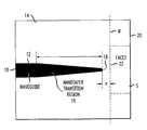
- FIG. 1is a top view of a conventional prior art “end-fire” nanotaper waveguide coupling arrangement
- FIG. 2is a top view of an exemplary nanotaper waveguide coupling arrangement including an etched coupling facet formed in accordance with the present invention
- FIG. 3is a generalized view of an exemplary wafer which may be processed to form a plurality of etched facets on a plurality of optical structures formed therein;
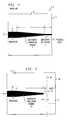
- FIG. 4is a graph illustrating the improvement in coupling efficiency between the prior art arrangement of FIG. 1 and the inventive structure of FIG. 2 ;
- FIG. 5contains a top view of an alternative embodiment of the present invention, in this case for use with a standard optical waveguide endface (that is, not a nanotaper coupler) and comprising a front-to-back angled facet, created with a etching process;
- a standard optical waveguide endfacethat is, not a nanotaper coupler
- a front-to-back angled facetcreated with a etching process
- FIG. 6is a side view of an alternative angled facet arrangement of the present invention, in this case with the angle created in the plane of the substrate endface;
- FIG. 7is a top view of yet another embodiment of the present invention, illustrating the formation of an etched curvature along the substrate endface to form a lensed coupling facet;
- FIG. 8illustrates a compound lensed coupling facet formed using a pre-defined pattern and subsequent etch process to create each desired contour along the optical axis between the waveguide and substrate endface;
- FIG. 9is a top view of an array embodiment of the present invention, in this case with a plurality of curved facets formed with an etch process in a manner where each facet is aligned with a separate waveguide within a waveguide array;
- FIG. 10is a top view of a prior art optical system including an off-chip laser transmitter and focusing element as used in conjunction with a nanotaper waveguide formed on an optical substrate, indicating problems associated with reflections that will be re-directed back into the laser component;
- FIG. 11is a top view of an arrangement of an optical system formed in accordance with present invention where the endface facet of the optical substrate is contoured by an etch process to de-focus any reflected signal and direct it away from the active region of the laser transmitter;
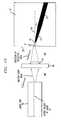
- FIG. 12is a top view of an alternative optical system of the present invention, formed to include an angled facet formed using an etch process to direct a reflected beam away from the optical axis;
- FIG. 13illustrates an alternative embodiment of the configuration of FIG. 11 , in this case where the nanotaper is angularly disposed to improve coupling efficiency.
- FIG. 1is a top view of an exemplary optical substrate 1 formed to include an optical waveguide 2 which also includes a nanotaper transition region 3 and a nanotaper tip region 4 .
- optical substrate 1is an SOI-based substrate comprising a base layer of silicon (not shown in this top view), an overlying dielectric (silicon dioxide) layer 5 (also referred to as “buried oxide layer 5 ” or “BOX layer 5 ” in the following) and a single crystal, sub-micron thick silicon surface layer 6 (also referred to as SOI layer 6 ).
- optical waveguide 2(as well as adjoining regions 3 and 4 ) are formed within SOI layer 6 .
- the remainder of the exposed surface in this top viewis, therefore, BOX layer 5 .
- one prior art technique for preparing nanotaper tip region 4 to receive an optical signalis to polish the endface of the optical substrate. In the arrangement of FIG. 1 , this would require polishing endface 7 of substrate 1 .
- conventional polishing techniquessuch as, for example, chemical-mechanical polishing systems
- nanotaper tip region 4needs to be formed of a predetermined length L to accommodate for this polishing inaccuracy.
- the prior art polishing methodWhile needing to provide this additional tip region, the prior art polishing method also suffers from the scattering and reflection problems discussed above. Formation of the endface facet using a prior art cleaving process also suffers from drawbacks, particularly related to locating and defining the crystalline plane used to create the cleave.
- FIG. 1the prior art illustration of FIG. 1 , as well as the remaining drawings illustrating the present invention, do not illustrate every feature of the final structure (for the sake of clarity).
- a dielectric layeris usually included as a top, covering layer (referred to as an “interlevel dielectric layer” or “ILD” in the art), but is not illustrated so that waveguide 2 is visible in a top view.
- ILDinterlevel dielectric layer
- the etched coupling facets of the present inventionmay be used with other material systems within which optical waveguides are formed including, but not limited to, silicon oxynitride optical waveguides or silicon nitride optical waveguides.
- FIG. 2illustrates an etched facet formed in accordance with the present invention to provide coupling between an optical waveguide and a free space optical signal.
- An optical waveguide 10is shown as formed in an SOI layer 12 of an SOI-based optical arrangement (which includes a silicon base layer, not shown, and an overlying BOX layer 14 ).
- optical waveguide 10is formed to include a nanotaper transition region 16 , where as discussed above, the use of a nanotaper is beneficial in situations where a larger optical mode size at the coupling interface is desired.
- an etched coupling facet 22is shown as being formed by removing a portion of BOX layer 14 from the area between nanotaper transition region 16 and SOI structure endface 20 (shown as shaded portion S in FIG. 2 ). More specifically, the waveguide cladding material—including both BOX layer 14 and the overlying ILD layer (not shown)—are removed by the etching process. The remainder of this discussion will thus refer to the removal of the “waveguide cladding material”, which is understood to include both BOX layer 14 and any overlying ILD cladding layer which may be presented.
- the etched coupling facet of the present inventionmay be used with other types of optical waveguides, such as silicon nitride waveguides or silicon oxynitride waveguides.
- a conventional patterning techniqueis used to define the boundaries of shaded portion S, so that a like area may be removed from each optical assembly formed across an entire wafer (see FIG. 3 for a wafer-level illustration, showing a plurality of patterned areas to be removed to form coupling facets).
- the specific geometry (variously referred to also as “contour”) of the region removed by etchingis at the discretion of the user. For example, it is possible to remove an entire width of the waveguide cladding material from endface 20 (shown by the dotted line “W” in FIG. 2 ), creating an etched facet endface 22 across the entire width of the optical substrate.
- nanotaper transition region 16is formed to include an endpoint termination 18 (hereinafter referred to as “tip 18 ”) which is disposed at a location which is pulled back from etched facet 22 formed in the manner described above.
- tip 18endpoint termination 18
- tip 18 of nanotaper transition region 16Several advantages have been discovered when using this pulled back placement of tip 18 of nanotaper transition region 16 .
- tip 18when tip 18 is located at the coupling facet, it will be exposed to air, which has a lower refractive index than BOX layer 14 . This difference in refractive index causes an increased portion of the incoming light signal to be scattered at tip 18 , significantly reducing coupling efficiency into nanotaper 16 .
- the pulled back location of nanotaper tip 18allows for the facet 22 to be shaped, using standard photolithographic patterning and etching processes, to form various facet geometries which will further increase coupling efficiency.
- the thickness “x” of the remaining waveguide cladding material beyond tip 18is also defined by this photolithographic process; obviously, the dimensions of the portion removed by the etching process are at the discretion of the designer.
- a significant benefit of the arrangement of the present inventionis that a plasma etching process forms an optically smooth surface, limiting the amount of scattering.
- a plasma etching processforms an optically smooth surface, limiting the amount of scattering.
- the use of a “dielectric/air” interfacealso minimizes the possibilities of scattering and reflection.
- a follow-on coating processmay be used to deposit an anti-reflective material along facet 22 ; again performed as a wafer-level process.
- FIG. 4is a graph of insertion loss as a function of nanotaper tip width (measured in nm).
- Curve Ais associated with the prior art arrangement of FIG. 1 (where the nanotaper tip is exposed at a polished endface of the SOI structure).
- the minimum insertion loss, on the order of 6 dBis associated with a nanotaper tip width of 200 nm. As the width either increases or decreases, the loss is seen to increase, reaching values of 12 dB or more.
- Curve Bis associated with the structure of the present invention as illustrated in FIG. 2 .
- the insertion loss plotis flatter than that of the prior art and again exhibits the minimum loss at a tip width of about 200 nm, in this case having a value of about 4 dB—a 2 dB improvement over the prior art.
- the lossincreases at a slower rate than the prior art and, in any case, does not exceed a value greater than about 7 dB.
- a plasma etching processmay be used to particularly angle the coupling facet to re-direct any reflected signals away from the active region of the laser source.
- FIG. 5illustrates an exemplary embodiment of the present invention which provides reflected signal re-direction.
- FIG. 5is a top view of the embodiment, illustrating the coupling of an optical signal into an endface 11 of optical waveguide 10 ; no nanotaper transition region is utilized in this particular embodiment (it is to be understood, however, that any embodiment may or may not include a nanotaper transition region, at the discretion of the user).
- an angled coupling facet 30is created which will successfully re-direct any reflected signal (shown by arrow “R”) out of the signal path of the incoming optical signal (shown by arrow “I”).
- the angled surfaceis created from “front to back” along the top surface of the substrate.
- the illustrated angle ⁇is selected to be sufficient to ensure that the reflected signal will propagate away from angled coupling facet 30 , while not unduly limiting the coupling efficiency into endface 11 of waveguide 10 .
- the use of angled coupling facet 30also eliminates the need to apply an anti-reflective (AR) coating on the facet, saving both fabrication time and expense.
- ARanti-reflective
- An angled facetmay also be formed in the vertical direction, as shown in the embodiment of FIG. 6 .
- a downwardly angled facet 32is formed using an etching process in accordance with the present invention.
- an incident ray Iwill be directed through the waveguide cladding material and couple into endface 11 of optical waveguide 10 .
- Reflected ray Ris shown as directed upward at an angle, away from the incoming optical axis.
- angled facet 32is formed at an angle ⁇ , controlled by the fabricator for the intended purpose of the device.
- FIG. 7is a top view of an exemplary embodiment of the present invention illustrating this advantage, where a focusing lens 35 is formed by etching a properly-contoured curvature along the endface of the optical substrate. As indicated by the arrows, an incoming collimated signal will be focused by lens 35 into the center portion of optical waveguide 10 at endface 11 .
- FIG. 8is a top view of an exemplary multi-component coupling facet, including a set of etched contours specifically patterned to form a first, focusing lens 34 and a second, collimating lens 36 .
- waveguide 10is formed to include nanotaper transition region 16 , terminating at nanotaper tip 18 .
- a cavity 40is created through the waveguide cladding material using a pattern and etch process that is controlled to create the necessary contours associated with focusing lens 34 and a first surface 33 of collimating lens 36 .
- a photolithographic mask having the contour of cavity 40is created on the surface of the waveguide cladding material. Thereafter, the exposed area is removed using a suitable etchant, leaving cavity 40 (which will advantageously exhibit the desired optically smooth surfaces).
- Outer surface 37 of collimating lens 36is also contoured using an etch process to provide the desired coupling facet geometry.
- FIG. 9is a top view of one exemplary array embodiment of the present invention, in this case illustrating a plurality of waveguides 10 - 1 , 10 - 2 , 10 - 3 , . . . , 10 -N utilizing a plurality of etched lenses 35 - 1 , 35 - 2 , 35 - 3 , . . . , 35 -N formed in the same manner as the embodiments described above.
- a single patterning stepmay be used to define the shape and location of the plurality of etched lenses 35 - 1 through 35 -N, providing alignment between the focal point of the lenses and endfaces 11 - 1 through 11 -N of waveguides 10 - 1 through 10 -N.
- the ability to replicate the same lens geometry across the arrayis seen to be a significant advantage of the use of etched coupling facet preparation in accordance with the present invention. While not shown, it is to be understood that an angled facet may be used with an array waveguide structure (instead of the illustrated lensed facet). In this case, both the facet angle and the angle of the waveguide array with respect to the substrate surface) can be controlled to provide optimum coupling (see FIG. 13 , below, for an illustration of an angled facet and an angled waveguide).
- FIG. 10is a top view of a prior art arrangement which exhibits this instability problem.
- a laser chip 50 including an active region 52is activated to emit an output beam which then propagates through the air and encounters a microlens element 54 held within a support element 56 .
- Microlens 54functions to focus the emitted beam toward nanotaper tip 18 of waveguide 10 , as shown.
- prior art coupling facet 7is formed by using, for example, a polishing process, a significant portion of the incoming beam will be reflected, shown by arrow labeled “Direction of reflected beam” in FIG. 10 .
- the on-axis component of this reflected beamwill pass unimpeded through microlens 54 and re-enter active region 52 of laser 50 , as shown.
- a coupling facet having an etched contourcan be formed along the endface of the optical substrate to minimize the optical energy directed back into the laser source.
- the etched coupling facetis shown as exhibiting a contour that will function as a lens 60 .
- the patterning of the endfaceis determined in conjunction with the parameters of the waveguide so as to focus the incoming laser beam into tip 18 of nanotaper 16 .
- the curvature of lens 6 balso re-directs any reflected portions of the beam away from the optical axis of the system (that is, “de-focuses” the reflected beam).
- optical design parameterse.g., focal length
- the optical design parameters of lens 60in combination with the optical parameters of microlens 54 , are chosen to optimize the coupling of the incident laser beam into nanotaper tip 18 while simultaneously scattering the reflected signal away from active region 52 .
- FIG. 12An alternative laser-based system using a contoured etched facet of the present invention is shown in FIG. 12 .
- an angled facet 62is formed along endface 20 of the optical substrate.
- the angled facetis formed as recessed within the optical substrate from endface 20 (in contrast to the angled facets illustrated above, which are shown as “notches”; either geometry is suitable for any embodiment of the present invention).
- the angle ⁇is selected to re-direct the reflected signal beyond the capture angle of microlens 54 , as shown in FIG. 12 .
- waveguide 10is formed to be slightly offset from the optical axis OA of the system.
- FIG. 13illustrates this configuration, where waveguide 10 (and associated nanotaper 18 ) is disposed at an angle of ⁇ with respect to optical axis OA.
Landscapes
- Physics & Mathematics (AREA)
- General Physics & Mathematics (AREA)
- Optics & Photonics (AREA)
- Optical Integrated Circuits (AREA)
- Optical Couplings Of Light Guides (AREA)
Abstract
Description
Claims (18)
Priority Applications (4)
| Application Number | Priority Date | Filing Date | Title |
|---|---|---|---|
| US12/316,540US8121450B2 (en) | 2007-12-12 | 2008-12-11 | Coupling between free space and optical waveguide using etched coupling surfaces |
| CN200880120350.4ACN101896846B (en) | 2007-12-12 | 2008-12-12 | Coupling between free space and optical waveguide using etched coupling surfaces |
| PCT/US2008/013665WO2009075888A1 (en) | 2007-12-12 | 2008-12-12 | Coupling between free space and optical waveguide using etched coupling surfaces |
| CA2708767ACA2708767C (en) | 2007-12-12 | 2008-12-12 | Coupling between free space and optical waveguide using etched coupling surfaces |
Applications Claiming Priority (3)
| Application Number | Priority Date | Filing Date | Title |
|---|---|---|---|
| US739407P | 2007-12-12 | 2007-12-12 | |
| US6292308P | 2008-01-30 | 2008-01-30 | |
| US12/316,540US8121450B2 (en) | 2007-12-12 | 2008-12-11 | Coupling between free space and optical waveguide using etched coupling surfaces |
Publications (2)
| Publication Number | Publication Date |
|---|---|
| US20090162013A1 US20090162013A1 (en) | 2009-06-25 |
| US8121450B2true US8121450B2 (en) | 2012-02-21 |
Family
ID=40755801
Family Applications (1)
| Application Number | Title | Priority Date | Filing Date |
|---|---|---|---|
| US12/316,540Active2029-03-22US8121450B2 (en) | 2007-12-12 | 2008-12-11 | Coupling between free space and optical waveguide using etched coupling surfaces |
Country Status (4)
| Country | Link |
|---|---|
| US (1) | US8121450B2 (en) |
| CN (1) | CN101896846B (en) |
| CA (1) | CA2708767C (en) |
| WO (1) | WO2009075888A1 (en) |
Cited By (17)
| Publication number | Priority date | Publication date | Assignee | Title |
|---|---|---|---|---|
| US9164235B1 (en)* | 2014-07-02 | 2015-10-20 | Cisco Technology, Inc. | Dual tip optical coupler |
| US9618699B2 (en) | 2015-03-15 | 2017-04-11 | Cisco Technology, Inc. | Multilayer photonic adapter |
| US20170160468A1 (en)* | 2015-12-03 | 2017-06-08 | Shinko Electric Industries Co., Ltd. | Light waveguide, method of manufacturing light waveguide, and light waveguide device |
| US9864133B2 (en) | 2015-11-13 | 2018-01-09 | Cisco Technology, Inc. | Silicon photonic chip with through VIAS |
| US9927574B2 (en) | 2013-05-21 | 2018-03-27 | International Business Machines Corporation | Optical component with angled-facet waveguide |
| US20190018198A1 (en)* | 2017-07-12 | 2019-01-17 | GM Global Technology Operations LLC | Photonic integrated circuit edge coupler structure with reduced reflection for integrated laser diodes |
| US10386237B2 (en) | 2016-02-10 | 2019-08-20 | Massachusetts Institute Of Technology | Apparatus, systems, and methods for on-chip spectroscopy using optical switches |
| US10571335B2 (en) | 2014-11-24 | 2020-02-25 | Massachusetts Institute Of Technology | Methods and apparatus for spectral imaging |
| US10615568B2 (en) | 2017-07-12 | 2020-04-07 | GM Global Technology Operations LLC | Antireflection structure for integrated laser diode/photonic chip interface |
| US10610087B2 (en) | 2015-07-24 | 2020-04-07 | Massachusetts Institute Of Technology | Apparatus, systems, and methods for biomedical imaging and stimulation |
| US10649138B2 (en) | 2018-09-21 | 2020-05-12 | Nokia Solutions And Networks Oy | Optical device having a photonic chip with one or more suspended functional portions |
| US10718668B2 (en) | 2017-08-08 | 2020-07-21 | Massachusetts Institute Of Technology | Miniaturized Fourier-transform Raman spectrometer systems and methods |
| US20200310120A1 (en)* | 2019-03-27 | 2020-10-01 | Facebook Technologies, Llc | Waveguide concentrator for light source |
| US10983003B2 (en) | 2019-02-11 | 2021-04-20 | Massachusetts Institute Of Technology | High-performance on-chip spectrometers and spectrum analyzers |
| US11041759B2 (en) | 2018-06-28 | 2021-06-22 | Massachusetts Institute Of Technology | Systems and methods for Raman spectroscopy |
| US11067750B2 (en) | 2019-01-28 | 2021-07-20 | Cisco Technology, Inc. | Silicon photonics platform with integrated oxide trench edge coupler structure |
| US11085998B2 (en) | 2019-10-29 | 2021-08-10 | GM Global Technology Operations LLC | Photonic edge coupler |
Families Citing this family (3)
| Publication number | Priority date | Publication date | Assignee | Title |
|---|---|---|---|---|
| US10481348B2 (en)* | 2016-09-09 | 2019-11-19 | miDiagnostics NV | Optical system for coupling light into a waveguide |
| CN113835158B (en)* | 2021-09-16 | 2024-01-12 | 中国科学院微电子研究所 | Free space light and photonic chip end-face coupling method |
| CN114217380B (en)* | 2021-12-17 | 2024-04-02 | 武汉光谷信息光电子创新中心有限公司 | End face coupler and preparation method thereof |
Citations (36)
| Publication number | Priority date | Publication date | Assignee | Title |
|---|---|---|---|---|
| US5142596A (en)* | 1990-07-24 | 1992-08-25 | Matsushita Electric Industrial Co., Ltd. | Tapered light wave guide and wavelength converting element using the same |
| JPH07152055A (en) | 1993-05-21 | 1995-06-16 | Matsushita Electric Ind Co Ltd | Short wavelength light source and variable wavelength laser light source |
| US5605600A (en)* | 1995-03-13 | 1997-02-25 | International Business Machines Corporation | Etch profile shaping through wafer temperature control |
| US6214178B1 (en) | 1998-12-22 | 2001-04-10 | Lucent Technologies, Inc. | Focused ion beam formation of angled optoelectronic devices |
| US6253007B1 (en)* | 1998-07-08 | 2001-06-26 | Optical Switch Corporation | Method and apparatus for connecting optical fibers |
| US6263133B1 (en)* | 1999-03-29 | 2001-07-17 | Scimed Life Systems, Inc. | Optical focusing, collimating and coupling systems for use with single mode optical fiber |
| US6328482B1 (en)* | 1998-06-08 | 2001-12-11 | Benjamin Bin Jian | Multilayer optical fiber coupler |
| US20020097956A1 (en)* | 2001-01-22 | 2002-07-25 | Juro Kikuchi | Fiber collimator array |
| US20020131699A1 (en)* | 2001-03-16 | 2002-09-19 | Raguin Daniel H. | Collimator array and method and system for aligning optical fibers to a lens array |
| US20030161603A1 (en)* | 2002-02-27 | 2003-08-28 | Nadeau Mary J. | Receiver optical bench formed using passive alignment |
| US20030161363A1 (en)* | 2002-02-27 | 2003-08-28 | Optronx, Inc. | Optical transmitter and transponder that operate without thermoelectric cooler |
| US6643068B2 (en)* | 1999-07-16 | 2003-11-04 | Michael J. Mandella | Collimators and collimator arrays employing ellipsoidal solid immersion lenses |
| US6647183B2 (en)* | 2000-01-25 | 2003-11-11 | Infineon Technologies Ag | Optical coupling system |
| US6751379B2 (en)* | 2000-11-01 | 2004-06-15 | Intel Corporation | System and method for collimating and redirecting beams in a fiber optic system |
| US6813417B2 (en) | 2002-02-20 | 2004-11-02 | Pacific Wave Industries, Inc. | Tapered waveguide interconnection structure and method of fabricating the same |
| US6821900B2 (en)* | 2001-01-09 | 2004-11-23 | Infineon Technologies Ag | Method for dry etching deep trenches in a substrate |
| US6884327B2 (en) | 2002-03-16 | 2005-04-26 | Tao Pan | Mode size converter for a planar waveguide |
| US6912345B2 (en) | 2001-03-30 | 2005-06-28 | Shipley Company, L.L.C. | Tapered optical fiber for coupling to diffused optical waveguides |
| US6985646B2 (en)* | 2003-01-24 | 2006-01-10 | Xponent Photonics Inc | Etched-facet semiconductor optical component with integrated end-coupled waveguide and methods of fabrication and use thereof |
| US6987912B2 (en) | 2002-05-31 | 2006-01-17 | Intel Corporation | Epitaxial growth for waveguide tapering |
| US6993225B2 (en) | 2004-02-10 | 2006-01-31 | Sioptical, Inc. | Tapered structure for providing coupling between external optical device and planar optical waveguide and method of forming the same |
| US7013067B2 (en) | 2004-02-11 | 2006-03-14 | Sioptical, Inc. | Silicon nanotaper couplers and mode-matching devices |
| US7024074B2 (en)* | 2002-09-30 | 2006-04-04 | Intel Corporation | System and method for packaging a monitor photodiode with a laser in an optical subassembly |
| US7031562B2 (en) | 2001-04-05 | 2006-04-18 | Luxtera, Inc. | Photonic input/output port |
| US7049672B2 (en)* | 2003-01-02 | 2006-05-23 | Intel Corporation | Method and apparatus for preparing a plurality of dice in wafers |
| US7065272B2 (en) | 2002-04-10 | 2006-06-20 | Interuniversitair Microelektronica Centrum (Imec Vzw) | Fiber-to-waveguide coupler |
| US7079741B2 (en) | 2000-09-29 | 2006-07-18 | Kabushiki Kaisha Toshiba | Optical interconnection circuit board and manufacturing method thereof |
| US7162124B1 (en) | 2003-03-14 | 2007-01-09 | Luxtera, Inc. | Fiber to chip coupler |
| US20070031088A1 (en) | 2004-01-15 | 2007-02-08 | University Of Delaware | Optical coupler for coupling an optical fiber into a waveguide |
| US7190864B2 (en) | 2004-04-02 | 2007-03-13 | Beamtek, Inc. | Fiber collimating lenses and method |
| US7251406B2 (en) | 2000-12-14 | 2007-07-31 | Shipley Company, L.L.C. | Optical waveguide termination with vertical and horizontal mode shaping |
| US7274835B2 (en) | 2004-02-18 | 2007-09-25 | Cornell Research Foundation, Inc. | Optical waveguide displacement sensor |
| US7285433B2 (en)* | 2003-11-06 | 2007-10-23 | General Electric Company | Integrated devices with optical and electrical isolation and method for making |
| US20080105940A1 (en) | 2006-06-15 | 2008-05-08 | Sioptical, Inc. | SOI-based inverse nanotaper optical detector |
| US7376317B2 (en) | 2003-10-27 | 2008-05-20 | Nec Corporation | Waveguide structure and method of manufacturing the same |
| US7415184B2 (en) | 2006-01-11 | 2008-08-19 | Sioptical Inc. | Wideband optical coupling into thin SOI CMOS photonic integrated circuit |
- 2008
- 2008-12-11USUS12/316,540patent/US8121450B2/enactiveActive
- 2008-12-12CACA2708767Apatent/CA2708767C/enactiveActive
- 2008-12-12WOPCT/US2008/013665patent/WO2009075888A1/enactiveApplication Filing
- 2008-12-12CNCN200880120350.4Apatent/CN101896846B/enactiveActive
Patent Citations (38)
| Publication number | Priority date | Publication date | Assignee | Title |
|---|---|---|---|---|
| US5142596A (en)* | 1990-07-24 | 1992-08-25 | Matsushita Electric Industrial Co., Ltd. | Tapered light wave guide and wavelength converting element using the same |
| JPH07152055A (en) | 1993-05-21 | 1995-06-16 | Matsushita Electric Ind Co Ltd | Short wavelength light source and variable wavelength laser light source |
| US5605600A (en)* | 1995-03-13 | 1997-02-25 | International Business Machines Corporation | Etch profile shaping through wafer temperature control |
| US6328482B1 (en)* | 1998-06-08 | 2001-12-11 | Benjamin Bin Jian | Multilayer optical fiber coupler |
| US6253007B1 (en)* | 1998-07-08 | 2001-06-26 | Optical Switch Corporation | Method and apparatus for connecting optical fibers |
| US6214178B1 (en) | 1998-12-22 | 2001-04-10 | Lucent Technologies, Inc. | Focused ion beam formation of angled optoelectronic devices |
| US6263133B1 (en)* | 1999-03-29 | 2001-07-17 | Scimed Life Systems, Inc. | Optical focusing, collimating and coupling systems for use with single mode optical fiber |
| US6643068B2 (en)* | 1999-07-16 | 2003-11-04 | Michael J. Mandella | Collimators and collimator arrays employing ellipsoidal solid immersion lenses |
| US6647183B2 (en)* | 2000-01-25 | 2003-11-11 | Infineon Technologies Ag | Optical coupling system |
| US7079741B2 (en) | 2000-09-29 | 2006-07-18 | Kabushiki Kaisha Toshiba | Optical interconnection circuit board and manufacturing method thereof |
| US6751379B2 (en)* | 2000-11-01 | 2004-06-15 | Intel Corporation | System and method for collimating and redirecting beams in a fiber optic system |
| US7251406B2 (en) | 2000-12-14 | 2007-07-31 | Shipley Company, L.L.C. | Optical waveguide termination with vertical and horizontal mode shaping |
| US6821900B2 (en)* | 2001-01-09 | 2004-11-23 | Infineon Technologies Ag | Method for dry etching deep trenches in a substrate |
| US6625350B2 (en)* | 2001-01-22 | 2003-09-23 | Osaki Electric Co., Ltd. | Fiber collimator array |
| US20020097956A1 (en)* | 2001-01-22 | 2002-07-25 | Juro Kikuchi | Fiber collimator array |
| US20020131699A1 (en)* | 2001-03-16 | 2002-09-19 | Raguin Daniel H. | Collimator array and method and system for aligning optical fibers to a lens array |
| US6912345B2 (en) | 2001-03-30 | 2005-06-28 | Shipley Company, L.L.C. | Tapered optical fiber for coupling to diffused optical waveguides |
| US7031562B2 (en) | 2001-04-05 | 2006-04-18 | Luxtera, Inc. | Photonic input/output port |
| US6813417B2 (en) | 2002-02-20 | 2004-11-02 | Pacific Wave Industries, Inc. | Tapered waveguide interconnection structure and method of fabricating the same |
| US20030161363A1 (en)* | 2002-02-27 | 2003-08-28 | Optronx, Inc. | Optical transmitter and transponder that operate without thermoelectric cooler |
| US20030161603A1 (en)* | 2002-02-27 | 2003-08-28 | Nadeau Mary J. | Receiver optical bench formed using passive alignment |
| US6884327B2 (en) | 2002-03-16 | 2005-04-26 | Tao Pan | Mode size converter for a planar waveguide |
| US7065272B2 (en) | 2002-04-10 | 2006-06-20 | Interuniversitair Microelektronica Centrum (Imec Vzw) | Fiber-to-waveguide coupler |
| US6987912B2 (en) | 2002-05-31 | 2006-01-17 | Intel Corporation | Epitaxial growth for waveguide tapering |
| US7024074B2 (en)* | 2002-09-30 | 2006-04-04 | Intel Corporation | System and method for packaging a monitor photodiode with a laser in an optical subassembly |
| US7049672B2 (en)* | 2003-01-02 | 2006-05-23 | Intel Corporation | Method and apparatus for preparing a plurality of dice in wafers |
| US6985646B2 (en)* | 2003-01-24 | 2006-01-10 | Xponent Photonics Inc | Etched-facet semiconductor optical component with integrated end-coupled waveguide and methods of fabrication and use thereof |
| US7162124B1 (en) | 2003-03-14 | 2007-01-09 | Luxtera, Inc. | Fiber to chip coupler |
| US7376317B2 (en) | 2003-10-27 | 2008-05-20 | Nec Corporation | Waveguide structure and method of manufacturing the same |
| US7285433B2 (en)* | 2003-11-06 | 2007-10-23 | General Electric Company | Integrated devices with optical and electrical isolation and method for making |
| US20070031088A1 (en) | 2004-01-15 | 2007-02-08 | University Of Delaware | Optical coupler for coupling an optical fiber into a waveguide |
| US7428358B2 (en) | 2004-01-15 | 2008-09-23 | University Of Delaware | Optical coupler for coupling an optical fiber into a waveguide |
| US6993225B2 (en) | 2004-02-10 | 2006-01-31 | Sioptical, Inc. | Tapered structure for providing coupling between external optical device and planar optical waveguide and method of forming the same |
| US7013067B2 (en) | 2004-02-11 | 2006-03-14 | Sioptical, Inc. | Silicon nanotaper couplers and mode-matching devices |
| US7274835B2 (en) | 2004-02-18 | 2007-09-25 | Cornell Research Foundation, Inc. | Optical waveguide displacement sensor |
| US7190864B2 (en) | 2004-04-02 | 2007-03-13 | Beamtek, Inc. | Fiber collimating lenses and method |
| US7415184B2 (en) | 2006-01-11 | 2008-08-19 | Sioptical Inc. | Wideband optical coupling into thin SOI CMOS photonic integrated circuit |
| US20080105940A1 (en) | 2006-06-15 | 2008-05-08 | Sioptical, Inc. | SOI-based inverse nanotaper optical detector |
Non-Patent Citations (1)
| Title |
|---|
| Almeida, et al., "Nanotaper for Compact Mode Conversion", Optics Letters/vol. 28, No. 15/ Aug. 1, 2003, 2003 Optical Society of America. |
Cited By (38)
| Publication number | Priority date | Publication date | Assignee | Title |
|---|---|---|---|---|
| US9927574B2 (en) | 2013-05-21 | 2018-03-27 | International Business Machines Corporation | Optical component with angled-facet waveguide |
| US10082625B2 (en) | 2013-05-21 | 2018-09-25 | International Business Machines Corporation | Optical component with angled-facet waveguide |
| US9164235B1 (en)* | 2014-07-02 | 2015-10-20 | Cisco Technology, Inc. | Dual tip optical coupler |
| US10571335B2 (en) | 2014-11-24 | 2020-02-25 | Massachusetts Institute Of Technology | Methods and apparatus for spectral imaging |
| US9618699B2 (en) | 2015-03-15 | 2017-04-11 | Cisco Technology, Inc. | Multilayer photonic adapter |
| US10610087B2 (en) | 2015-07-24 | 2020-04-07 | Massachusetts Institute Of Technology | Apparatus, systems, and methods for biomedical imaging and stimulation |
| US9864133B2 (en) | 2015-11-13 | 2018-01-09 | Cisco Technology, Inc. | Silicon photonic chip with through VIAS |
| US20170160468A1 (en)* | 2015-12-03 | 2017-06-08 | Shinko Electric Industries Co., Ltd. | Light waveguide, method of manufacturing light waveguide, and light waveguide device |
| US9958607B2 (en)* | 2015-12-03 | 2018-05-01 | Shinko Electric Industries Co., Ltd. | Light waveguide, method of manufacturing light waveguide, and light waveguide device |
| US10852190B2 (en) | 2016-02-10 | 2020-12-01 | Massachusetts Institute Of Technology | Apparatus, systems, and methods for on-chip spectroscopy using optical switches |
| US10386237B2 (en) | 2016-02-10 | 2019-08-20 | Massachusetts Institute Of Technology | Apparatus, systems, and methods for on-chip spectroscopy using optical switches |
| US10914821B2 (en) | 2017-07-12 | 2021-02-09 | GM Global Technology Operations LLC | Calibration and alignment of coherent lidar system |
| US11067670B2 (en) | 2017-07-12 | 2021-07-20 | GM Global Technology Operations LLC | Heterogeneously integrated chip-scale lidar system |
| US10564263B2 (en) | 2017-07-12 | 2020-02-18 | GM Global Technology Operations LLC | Chip-scale LIDAR with a single MEMS scanner in a compact optical package |
| US11226403B2 (en) | 2017-07-12 | 2022-01-18 | GM Global Technology Operations LLC | Chip-scale coherent lidar with integrated high power laser diode |
| US11092671B2 (en) | 2017-07-12 | 2021-08-17 | GM Global Technology Operations LLC | Laser diode optical frequency modulation linearization algorithm |
| US10615568B2 (en) | 2017-07-12 | 2020-04-07 | GM Global Technology Operations LLC | Antireflection structure for integrated laser diode/photonic chip interface |
| CN109254359A (en)* | 2017-07-12 | 2019-01-22 | 通用汽车环球科技运作有限责任公司 | Reduce the photonic integrated circuits edge couplers structure of the reflection of integrated laser diode |
| US20190018198A1 (en)* | 2017-07-12 | 2019-01-17 | GM Global Technology Operations LLC | Photonic integrated circuit edge coupler structure with reduced reflection for integrated laser diodes |
| US10914822B2 (en) | 2017-07-12 | 2021-02-09 | GM Global Technology Operations LLC | Dual-laser chip-scale lidar for simultaneous range-doppler sensing |
| US10976414B2 (en) | 2017-07-12 | 2021-04-13 | GM Global Technology Operations LLC | Heterogeneous integration of curved mirror structure for passive alignment in chip-scale lidar |
| US11002832B2 (en) | 2017-07-12 | 2021-05-11 | GM Global Technology Operations LLC | Chip-scale LIDAR with a single 2D MEMS scanner |
| US10718668B2 (en) | 2017-08-08 | 2020-07-21 | Massachusetts Institute Of Technology | Miniaturized Fourier-transform Raman spectrometer systems and methods |
| US11313725B2 (en) | 2017-08-08 | 2022-04-26 | Massachusetts Institute Of Technology | Miniaturized Fourier-transform Raman spectrometer systems and methods |
| US11041759B2 (en) | 2018-06-28 | 2021-06-22 | Massachusetts Institute Of Technology | Systems and methods for Raman spectroscopy |
| US11885684B2 (en) | 2018-06-28 | 2024-01-30 | Massachusetts Institute Of Technology | Systems and methods for Raman spectroscopy |
| US10649138B2 (en) | 2018-09-21 | 2020-05-12 | Nokia Solutions And Networks Oy | Optical device having a photonic chip with one or more suspended functional portions |
| US11067750B2 (en) | 2019-01-28 | 2021-07-20 | Cisco Technology, Inc. | Silicon photonics platform with integrated oxide trench edge coupler structure |
| US11885677B2 (en) | 2019-02-11 | 2024-01-30 | Massachusetts Institute Of Technology | High-performance on-chip spectrometers and spectrum analyzers |
| US10983003B2 (en) | 2019-02-11 | 2021-04-20 | Massachusetts Institute Of Technology | High-performance on-chip spectrometers and spectrum analyzers |
| US20200310120A1 (en)* | 2019-03-27 | 2020-10-01 | Facebook Technologies, Llc | Waveguide concentrator for light source |
| US11493760B2 (en)* | 2019-03-27 | 2022-11-08 | Meta Platforms Technologies LLC | Waveguide concentrator for light source |
| US11960092B2 (en) | 2019-03-27 | 2024-04-16 | Meta Platforms Technologies, Llc | Waveguide concentrator for light source |
| US11085998B2 (en) | 2019-10-29 | 2021-08-10 | GM Global Technology Operations LLC | Photonic edge coupler |
| US11796644B2 (en) | 2019-10-29 | 2023-10-24 | GM Global Technology Operations LLC | Apparatus and system for a LiDAR antenna |
| US11644544B2 (en) | 2019-10-29 | 2023-05-09 | GM Global Technology Operations LLC | LiDAR device including a pseudo-random optical phased array |
| US11639988B2 (en) | 2019-10-29 | 2023-05-02 | GM Global Technology Operations LLC | Photonic circulator for a LiDAR device |
| US11500072B2 (en) | 2019-10-29 | 2022-11-15 | GM Global Technology Operations LLC | Photonic circulator for a LiDAR device |
Also Published As
| Publication number | Publication date |
|---|---|
| CA2708767C (en) | 2017-09-19 |
| US20090162013A1 (en) | 2009-06-25 |
| CA2708767A1 (en) | 2009-06-18 |
| CN101896846A (en) | 2010-11-24 |
| CN101896846B (en) | 2013-02-06 |
| WO2009075888A1 (en) | 2009-06-18 |
Similar Documents
| Publication | Publication Date | Title |
|---|---|---|
| US8121450B2 (en) | Coupling between free space and optical waveguide using etched coupling surfaces | |
| KR101258725B1 (en) | Wideband optical coupling into thin soi cmos photonic integrated circuit | |
| US6993225B2 (en) | Tapered structure for providing coupling between external optical device and planar optical waveguide and method of forming the same | |
| US7020364B2 (en) | Permanent light coupling arrangement and method for use with thin silicon optical waveguides | |
| US7013067B2 (en) | Silicon nanotaper couplers and mode-matching devices | |
| US7366379B2 (en) | Optical component for free-space optical propagation between waveguides | |
| US8031991B2 (en) | Low index, large mode field diameter optical coupler | |
| US7943894B2 (en) | Optical element for free-space propagation between an optical waveguide and another optical waveguide, component, or device | |
| RU2161323C2 (en) | Device and process of passive matching of optical fiber with input/output light guide ( versions ) | |
| CN110268588A (en) | Surface Coupled Laser with Optical Interposer | |
| WO2013048411A1 (en) | Vertical optical coupler for planar photonic circuits | |
| US10302871B2 (en) | Microfabricated fiber optic platform | |
| CN106461895A (en) | System and apparatus for free space optical coupling | |
| US20190353844A1 (en) | Optical module | |
| JPH07110410A (en) | Optical path converting circuit | |
| US20040151431A1 (en) | Lensed fiber having small form factor and method of making the same | |
| US20020071636A1 (en) | Method and apparatus for attaching an optical fibre to an optical device | |
| US20210041631A1 (en) | Fiber module | |
| US10551562B1 (en) | Anti-reflective and resonant waveguide grating to free-space couplers | |
| Taillaert et al. | Efficient coupling between submicron SOI-waveguides and single-mode fibers | |
| US10107962B2 (en) | Reduction of back reflections | |
| WO2004088715A2 (en) | Tapered structure for providing coupling between external optical device and planar optical waveguide and method of forming the same |
Legal Events
| Date | Code | Title | Description |
|---|---|---|---|
| AS | Assignment | Owner name:LIGHTWIRE, INC.,PENNSYLVANIA Free format text:ASSIGNMENT OF ASSIGNORS INTEREST;ASSIGNORS:WEBSTER, MARK;PATEL, VIPULKUMAR;NADEAU, MARY;AND OTHERS;REEL/FRAME:022048/0123 Effective date:20081205 Owner name:LIGHTWIRE, INC., PENNSYLVANIA Free format text:ASSIGNMENT OF ASSIGNORS INTEREST;ASSIGNORS:WEBSTER, MARK;PATEL, VIPULKUMAR;NADEAU, MARY;AND OTHERS;REEL/FRAME:022048/0123 Effective date:20081205 | |
| STCF | Information on status: patent grant | Free format text:PATENTED CASE | |
| AS | Assignment | Owner name:CISCO SYSTEMS, INC., CALIFORNIA Free format text:SECURITY AGREEMENT;ASSIGNOR:LIGHTWIRE, INC.;REEL/FRAME:027812/0631 Effective date:20120301 | |
| AS | Assignment | Owner name:LIGHTWIRE, INC., CALIFORNIA Free format text:RELEASE BY SECURED PARTY;ASSIGNOR:CISCO SYSTEMS, INC.;REEL/FRAME:028078/0927 Effective date:20120418 | |
| AS | Assignment | Owner name:LIGHTWIRE LLC, DELAWARE Free format text:CHANGE OF NAME;ASSIGNOR:LIGHTWIRE, INC.;REEL/FRAME:029275/0040 Effective date:20120320 Owner name:CISCO TECHNOLOGY, INC., CALIFORNIA Free format text:ASSIGNMENT OF ASSIGNORS INTEREST;ASSIGNOR:LIGHTWIRE LLC;REEL/FRAME:029275/0050 Effective date:20121018 | |
| FPAY | Fee payment | Year of fee payment:4 | |
| MAFP | Maintenance fee payment | Free format text:PAYMENT OF MAINTENANCE FEE, 8TH YR, SMALL ENTITY (ORIGINAL EVENT CODE: M2552); ENTITY STATUS OF PATENT OWNER: SMALL ENTITY Year of fee payment:8 | |
| FEPP | Fee payment procedure | Free format text:ENTITY STATUS SET TO UNDISCOUNTED (ORIGINAL EVENT CODE: BIG.); ENTITY STATUS OF PATENT OWNER: LARGE ENTITY | |
| MAFP | Maintenance fee payment | Free format text:PAYMENT OF MAINTENANCE FEE, 12TH YEAR, LARGE ENTITY (ORIGINAL EVENT CODE: M1553); ENTITY STATUS OF PATENT OWNER: LARGE ENTITY Year of fee payment:12 |