US8120932B2 - Low voltage ride through - Google Patents
Low voltage ride throughDownload PDFInfo
- Publication number
- US8120932B2 US8120932B2US12/165,921US16592108AUS8120932B2US 8120932 B2US8120932 B2US 8120932B2US 16592108 AUS16592108 AUS 16592108AUS 8120932 B2US8120932 B2US 8120932B2
- Authority
- US
- United States
- Prior art keywords
- power
- current
- wind turbine
- converter
- signal
- Prior art date
- Legal status (The legal status is an assumption and is not a legal conclusion. Google has not performed a legal analysis and makes no representation as to the accuracy of the status listed.)
- Expired - Fee Related, expires
Links
- 238000012937correctionMethods0.000claimsdescription22
- 239000003990capacitorSubstances0.000claimsdescription14
- 230000001105regulatory effectEffects0.000claimsdescription6
- 230000001276controlling effectEffects0.000claimsdescription3
- 230000005284excitationEffects0.000claimsdescription2
- 238000006243chemical reactionMethods0.000description17
- 238000010248power generationMethods0.000description13
- 230000003068static effectEffects0.000description9
- 230000004044responseEffects0.000description6
- 230000005611electricityEffects0.000description5
- 230000001052transient effectEffects0.000description5
- 230000005540biological transmissionEffects0.000description4
- 230000006698inductionEffects0.000description4
- 238000000034methodMethods0.000description4
- 230000006399behaviorEffects0.000description3
- 230000008859changeEffects0.000description2
- 238000013461designMethods0.000description2
- 230000008569processEffects0.000description2
- 238000012546transferMethods0.000description2
- 238000013459approachMethods0.000description1
- 230000033228biological regulationEffects0.000description1
- 230000007423decreaseEffects0.000description1
- 230000003292diminished effectEffects0.000description1
- 230000000694effectsEffects0.000description1
- 230000001939inductive effectEffects0.000description1
- 238000011084recoveryMethods0.000description1
- 230000002441reversible effectEffects0.000description1
- 239000004065semiconductorSubstances0.000description1
- 230000001360synchronised effectEffects0.000description1
Images


Classifications
- H—ELECTRICITY
- H02—GENERATION; CONVERSION OR DISTRIBUTION OF ELECTRIC POWER
- H02J—CIRCUIT ARRANGEMENTS OR SYSTEMS FOR SUPPLYING OR DISTRIBUTING ELECTRIC POWER; SYSTEMS FOR STORING ELECTRIC ENERGY
- H02J9/00—Circuit arrangements for emergency or stand-by power supply, e.g. for emergency lighting
- H02J9/04—Circuit arrangements for emergency or stand-by power supply, e.g. for emergency lighting in which the distribution system is disconnected from the normal source and connected to a standby source
- H02J9/06—Circuit arrangements for emergency or stand-by power supply, e.g. for emergency lighting in which the distribution system is disconnected from the normal source and connected to a standby source with automatic change-over, e.g. UPS systems
- H02J9/062—Circuit arrangements for emergency or stand-by power supply, e.g. for emergency lighting in which the distribution system is disconnected from the normal source and connected to a standby source with automatic change-over, e.g. UPS systems for AC powered loads
- Y—GENERAL TAGGING OF NEW TECHNOLOGICAL DEVELOPMENTS; GENERAL TAGGING OF CROSS-SECTIONAL TECHNOLOGIES SPANNING OVER SEVERAL SECTIONS OF THE IPC; TECHNICAL SUBJECTS COVERED BY FORMER USPC CROSS-REFERENCE ART COLLECTIONS [XRACs] AND DIGESTS
- Y02—TECHNOLOGIES OR APPLICATIONS FOR MITIGATION OR ADAPTATION AGAINST CLIMATE CHANGE
- Y02B—CLIMATE CHANGE MITIGATION TECHNOLOGIES RELATED TO BUILDINGS, e.g. HOUSING, HOUSE APPLIANCES OR RELATED END-USER APPLICATIONS
- Y02B10/00—Integration of renewable energy sources in buildings
- Y02B10/70—Hybrid systems, e.g. uninterruptible or back-up power supplies integrating renewable energies
- Y—GENERAL TAGGING OF NEW TECHNOLOGICAL DEVELOPMENTS; GENERAL TAGGING OF CROSS-SECTIONAL TECHNOLOGIES SPANNING OVER SEVERAL SECTIONS OF THE IPC; TECHNICAL SUBJECTS COVERED BY FORMER USPC CROSS-REFERENCE ART COLLECTIONS [XRACs] AND DIGESTS
- Y02—TECHNOLOGIES OR APPLICATIONS FOR MITIGATION OR ADAPTATION AGAINST CLIMATE CHANGE
- Y02E—REDUCTION OF GREENHOUSE GAS [GHG] EMISSIONS, RELATED TO ENERGY GENERATION, TRANSMISSION OR DISTRIBUTION
- Y02E10/00—Energy generation through renewable energy sources
- Y02E10/70—Wind energy
- Y02E10/76—Power conversion electric or electronic aspects
Definitions
- This applicationrelates to wind turbine generators (WTGs).
- Wind energyhas emerged as the fastest growing source of energy, offering a clean, renewable, and ecological-friendly alternative to fossil-based energy supplies. At the present growth rate, wind energy conversion is projected to produce more than 117,000 MW by the year of 2009, claiming about 1.25% of the global electricity generation.
- wind turbine generatorsare now increasingly installed in large-scale (e.g., multi-megawatt) wind farms and integrated into power grids that can deliver electricity to consumers nationwide.
- the performance of a grid-connected WTGcan be influenced by many factors, such as voltage fluctuations on the grid. For example, a short circuit on the grid may result in a sudden voltage drop, which reduces the effective drag on the WTG and may cause both the turbine and the generator to accelerate rapidly.
- some WTGshave been designed to trip off-line (i.e., disconnect from the grid and shut down) as soon as grid voltage drops below a prescribed level (e.g., 85% of nominal voltage). After fault clearance, these WTGs enter a restart cycle that can last several minutes before resuming power transmission to the grid.
- the Spanish Grid Coderequires WTGs to be able to sustain (“ride-through”) line voltage at 20% of rated level for at least 500 ms.
- FIG. 1Ashows an example of voltage transients when a low-voltage event occurs. In this case, after an initial dip of 500 ms, line voltage starts to recover and within 15 seconds has returned to 95% of nominal. During the entire low-voltage period ( ⁇ 15 s), the Spanish Grid Code requires WTGs to continue to operate and supply current in controlled amounts to help stabilize the grid.
- FIG. 1Bshows the required current behavior, measured by the ratio of the magnitude of reactive current to total current (I reactive /I total ) as a function of line voltage. Note that other countries may have different regulations on grid-connected WTGs' current and voltage behaviors in response to low voltage disturbances.
- a systemfor connecting a wind turbine generator to a utility power network.
- a first power converterconverts an AC signal from the wind turbine generator to a DC signal and supplies a controlled amount of reactive current to the wind turbine generator.
- a second power converterconnected in series with the first converter, converts the DC signal from the first power converter to a line-side AC signal and supplies a controlled amount of current to the utility power network.
- a power dissipation elementis coupled to the first and second power converters for dissipating power from the first power converter.
- Embodiments of this aspect of the inventionmay include one or more of the following features.
- the amount of current supplied to the utility power networksatisfies a predetermined criterion associated with a voltage condition of the utility power network.
- the predetermined criterionmay include that when a voltage of the utility power network falls below a predetermined threshold, the magnitude of reactive current supplied to the utility power network is at least twice as much as the magnitude of real current supplied to the utility power network.
- the first and second power convertersare connected via a DC bus.
- a capacitoris coupled to the DC bus.
- a first and second AC filter reactormay be coupled to the first and second power converter, respectively.
- the power dissipation elementmay include a resistor.
- the resistormay include a dynamic braking resistor.
- a controllable switching devicemay be coupled to the resistor for regulating a current passing through the resistor.
- a power factor correction unitmay be provided for adjusting a power factor of the electric power supplied to the utility power network.
- the power factor correction unitmay include a controllable capacitor that can be switched on and off by electrical signals.
- a control systemfor controlling an interconnection between a wind turbine generator and a utility power network.
- the control systemelectrically opens a first path of the interconnection.
- a second path of the interconnectionis controlled during the low voltage event to provide a first current suitable for maintaining an operation of the wind turbine generator and a second current having a predetermined characteristic associated with an operation of the utility power network.
- Embodiments of this aspect of the inventionmay include one or more of the following features.
- the control systemmay determine the occurrence of a low voltage event based on a voltage condition associated with the utility power network, or alternatively, on a current condition associated with the wind turbine generator, or a combination of both of these methods.
- the first currentincludes a reactive current component sufficient for maintaining an excitation of the wind turbine generator.
- the second currentincludes a real current component and a reactive current component. During the low voltage event, the second current is controlled so that the magnitude of the reactive current component is at least twice the magnitude of the real current component.
- the first pathincludes a switch unit controllable by external signals, and may further include a forced commutation circuit configured to provide a commutation signal to the switch unit.
- the second pathincludes a first power converter for converting AC power from the wind turbine generator to DC power and for providing the first current.
- a second power converteris connected in series with the first converter for converting the DC power from the first power converter to line-side AC power and for providing the second current.
- a power dissipation elementis coupled to the first and second power converter for dissipating power from the first power converter.
- the power dissipation elementmay include a resistor and a controllable switching device coupled to the resistor configured for regulating a current passing through the resistor.
- a capacitoris coupled to the first and second power converter.
- the control systemmay further control a power factor correction unit to adjust a power factor of the electric power supplied to the utility power network.
- the power factor correction unitmay include a controllable capacitor that can be switched on and off by electrical signals.
- a system for connecting a wind turbine generator to a utility power networkis provided.
- electric power generated by the WTGcan be delivered to the utility power network with near unity power factor and negligible power loss in the LVRT system (e.g., less than 0.3%).
- the systemmaintains near nominal voltages at generator terminals and provides sufficient impedance to the generator.
- the WTGcontinues to operate without experiencing low-voltage impacts (e.g., over-speeding).
- the amounts of real and reactive power delivered to the networkcan also be controlled based on voltage conditions.
- reactive powercan be injected to the grid in sufficient amounts (e.g., at least twice the amount of real power) to help stabilize the utility network in a major low voltage event.
- sufficient amountse.g., at least twice the amount of real power
- proper selection of power electronics and circuit designcan also reduce system response time to faults.
- FIGS. 1A and 1Billustrate some aspects of LVRT requirements in the Spanish Grid Code.
- FIGS. 2A and 2Bprovide an overview and an exemplary implementation of a wind power generation system with LVRT capability, respectively.
- FIG. 3is a flow chart illustrating a control scheme of the wind power generation system.
- FIGS. 4A to 4Dare examples of steady-state and transient operations of one implementation of the wind power generation system.
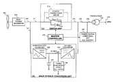
- a wind power generation system 200 with LVRT capabilityincludes a rotor 202 (e.g., a low speed propeller) which drives a wind turbine generator 204 for converting wind power to electric power in the form of alternating current (AC).
- a rotor 202e.g., a low speed propeller
- ACalternating current
- a transformer 242which by stepping up the AC voltage, transmits the power to a local grid 244 .
- the interconnection system 208includes a switch unit 210 and a back-to-back conversion unit 220 , which provide a first and second paths 211 and 221 respectively, between the generator 204 and the transformer 242 .
- switch unit 210can be electrically turned “ON” (closed) or “OFF” (open) by external signals (e.g., control signals) to allow or block current passage in first path 211 .
- Switch unit 210can be a single power electronic switch (e.g., a thyristor), or a circuit that functions essentially as an electric switch having at least two states of distinct impedance.
- switch unit 210presents negligible impedance to the current generated by the generator 204 , thereby minimizing potential power loss during transmission.
- switch unit 210When the grid is operating under normal conditions (e.g., voltage fluctuation remains within ⁇ 10% of nominal), switch unit 210 is closed, allowing power from the generator to be transmitted via first path 211 to transformer 236 in full capacity. When a low voltage event occurs (e.g., grid voltage drops below 90% of nominal), switch unit 210 is quickly opened to block first path 211 . Subsequently, the full output of the generator is delivered through second path 221 to back-to-back conversion unit 220 . When the grid voltage drops significantly to, for example, one-fifth its nominal value (i.e. 20%), five times nominal current will flow for the grid to absorb the pre-sag power generated by the WTG.
- the grid voltagedrops significantly to, for example, one-fifth its nominal value (i.e. 20%)
- back-to-back conversion unit 220provides power in controlled amounts based on voltage conditions.
- back-to-back conversion unit 220also provides reactive current necessary to excite generator 204 so that the generator continues to operate and generate power without being affected by the voltage drop.
- Other functions of the back-to-back conversion unitinclude a means to absorb or dissipate the excess power from the WTG that cannot be absorbed by the grid and, optionally, provide reactive current to the grid to aid in post-fault voltage recovery, which is described in greater detail below.
- a master controller 270is provided in interconnection system 208 to control power transmission between the generator and the grid.
- master controller 270is able to detect low voltage faults (as will be described in greater detail below) and act upon these faults to coordinate and control the operations of the switch and conversion units 210 and 220 to provide LVRT features of this power generation system.
- the implementation and logic of master controller 270will be described in greater detail in the context of an exemplary interconnection system provided below.
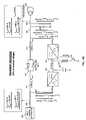
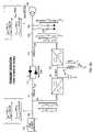
- FIG. 2Ban exemplary implementation of the interconnection system 208 shown in FIG. 2A is provided.
- switch unit 210back-to-back conversion unit 220 , master controller 270 , and an optional power factor correction unit 234 is described in the following sections.
- Switch unit 210includes a static switch 212 consisting of two controllable semiconductor switching devices, here, thyristors 212 a and 212 b . When closed, the pair of thyristors conducts AC current in alternative half-cycles, allowing the full output of the generator through the first path 211 with near zero voltage drop.
- thyristors 212 a and 212 bare selected to be “over-sized” (i.e., current ratings higher than required) to minimize on-state power consumption.
- switch unit 210has a built-in forced commutation circuit 214 to which the thyristors are connected.
- the forced commutation circuit 214When a control signal is received by the forced commutation circuit 214 , the commutation circuit generates a current pulse of sufficient magnitude with a polarity that generates a zero crossover of current with the thyristors.
- the static switch 212By forced commutation, the static switch 212 can be quickly turned off to help reduce system response time and improve transient performance.
- the back-to-back converters 222 and 224can be controlled to also generate a commutation current pulse in the static switch thyristors 212 .
- Back-to-back conversion unit 220includes a generator-side AC/DC converter 222 and a line-side DC/AC converter 224 connected in series via a DC bus 225 . Also coupled to DC bus 225 are one or multiple DC bus capacitors 226 which supports a DC bus voltage V dc , and a power dissipation device 228 capable of dissipating real power. Power dissipation device 228 can include for example, a resistor (e.g., a dynamic braking resistor) to dissipate real power, and a controllable switching device that controls the amount of current passing through the resistor. In some examples, AC filter reactors (not shown) for reducing undesired harmonics and distortion in AC signals are also provided on both the generator and line sides.
- a resistore.g., a dynamic braking resistor
- back-to-back conversion unit 220receives the full output power of the generator while passing only a safe amount of power onto the grid. Real power in excess of the safe amount is dissipated by power dissipation device 228 .
- power generation system 200can ride through severe voltage drops without either 1) sending large amounts of current through transformer 242 (which may potentially damage the transformer and trip the turbine generator on over-current); or 2) increasing the speed of the turbine generator (which may potentially trip the generator on over-speed).
- line-side converter 224is configured to provide not only real power but also reactive power in controlled amounts (e.g., reactive power at least twice as much as real power) to grid 244 .
- the exact ratio of reactive to real powermay be arbitrarily set or imposed by applicable grid interconnection requirements (e.g. the Spanish Grid Code).
- generator-side converter 222also provides reactive current necessary to keep the generators excited and operating at constant speed during low voltage events while simultaneously absorbing the real power output of the generator.
- generator-side converter 222For some wind turbine generators (e.g., induction generators) that require reactive power to establish and sustain their electric and magnetic fields, generator-side converter 222 also provides reactive current necessary to keep the generators excited and operating at constant speed during low voltage events while simultaneously absorbing the real power output of the generator. In these type of generators, without the reactive current being applied under low voltage conditions, the generator sees reduced torque and begins to accelerate rapidly, which can damage the WTG.
- a power factor correction unit 234is optionally coupled to line-side terminal 232 for improving the power factor (PF) of the electricity delivered to utility grids.
- PFpower factor
- PFis a dimensionless number between 0 and 1, representing the ratio of real power to total power (also referred to as apparent power).
- a power factor of zeroindicates that energy flow in the circuit is entirely reactive and stored energy in the load returns to the source on each cycle, whereas a power factor of unity indicates that energy flow is entirely real and thus uni-directional from source to load. Under normal conditions, it is generally desirable to operate power generation systems at near unity power factor to provide high efficiency power to utility grids.
- power factor correction unit 232includes a group of capacitors that can be individually switched on and off by means of contactors (e.g., electrically controlled switches). During normal operation, these capacitors provide reactive power in adjustable amounts (e.g., depending on the number of capacitors switched on) to help achieve near unity power factor (e.g., above 0.9) at grid connection points.
- This power factor correction unit 232may be provided as part of an existing wind turbine system, the interconnection system 208 , or a combination of both.
- Master controller 270is coupled to each of static switch 212 , forced commutation circuit 214 , back-to-back conversion unit 220 , and possibly other components in interconnection system 208 . Master controller 270 oversees system operation and controls power transmission between the generator and the grid based on various grid conditions.
- the master controlleruses feedback signals from multiple sensors (e.g., line-side and generator-side current/voltage sensors) to monitor current/voltage dynamics for determining system states. If the system is operating in steady state (step 310 )—that is, grid voltage appears within ⁇ 10% of nominal, the master controller functions to maintain the on-state of the switch unit 210 and disable/disconnect the back-to-back conversion unit 220 . As a result, power is transmitted to the transformer only through first path 211 .
- sensorse.g., line-side and generator-side current/voltage sensors
- Line faultsincluding both unbalanced faults and sudden voltage drops, can be detected by the master controller upon sensing voltage or current anomalies.
- a line faultis often followed by generator current exceeding a preset instantaneous level (e.g., 120% of nominal depending on system configuration), or line voltage falling below a preset threshold (e.g., 90% of nominal).
- a preset instantaneous levele.g. 120% of nominal depending on system configuration
- line voltage falling below a preset thresholde.g. 90% of nominal
- One way to turn off switch unit 210is to command forced commutation circuit 214 to generate a defined width commutation current pulse to commutate off the thyristor ( 212 a or 212 b ) that is in its conducting state. Pulse polarity can be determined as a function of generator current polarity.
- An alternative way to turn off the switch unituses the generator-side and/or line-side converter. Current is injected by the converter in reverse direction to the existing current in thyristors, thereby creating zero current crossover that biases the thyristors off-state. In some systems, having a converter on each side of the switch unit helps offset source impedance effects that often contribute to the delay in thyristors' response time (i.e. line impedance limiting the rate of change in the commutation current). This commutation process can occur simultaneously on all three phases of the LVRT system regardless of how many line phases are faulted.
- master controller 270controls the operation of back-to-back conversion unit 220 to provide LVRT capability.
- the desired output of conversion unit 220may vary depending on system design in compliance with specific grid connection standards. For example, to meet the requirements in the Spanish Grid Code, master controller 270 regulates conversion unit 220 so that 1) generator-side converter 222 receives generator power and provides reactive power to keep the generator excited and rotating at constant speed; and 2) line-side converter 224 supplies a safe amount of real power to grid 244 and injects sufficient reactive power to help stabilize the grid.
- Generator power in excess of the amount that can be safely absorbed by grid 244is dissipated by power dissipation device 228 , which consumes power in response to a regulated DC bus voltage, or can be controlled directly by matching the power dissipated to the excess generator power.
- master controller 270also controls power factor correction unit 234 to provide reactive power in suitable amounts for improving power factor at gird connection points.
- generator side converter 222synchronizes the generator voltage and phase to that of the grid (step 360 ) and switch unit 210 is quickly turned on (step 370 ). With back-to-back conversion unit 220 disconnected again from the generator, the system returns to steady state operation (step 310 ), feeding generator power through the first path 211 to the transformer 242 .
- FIGS. 4A to 4Dfurther illustrate how an interconnection system operates to provide satisfactory electric power to utility grids in ways that conform to the Spanish Grid Code. Circuit performance during each of several stages, including a steady state and multiple transient states following a low voltage event, is described in detail below.
- wind power generation system 200is operating in steady state with line-side voltage at nearly 100% of rated level. In this case, 706 kW of real power produced by turbine generator 204 is delivered entirely through switch unit 212 to transformer 242 , with less than 0.3% of energy loss. No power passes through generator-side converter 222 , line-side converter 224 , or the power dissipation device (e.g., a resistor 227 ).
- the power factor correction unite.g., a set of capacitors 233
- electricityis being provided to the grid at a power factor of unity.
- line-side converter 224starts to operate to supply both real and reactive current to AC line 232 .
- the amount of real and reactive current transferred by line-side converter 224is controlled such that the reactive power is twice the real power (e.g., 134 kVAR and 67 kW, respectively) and the total current does not significantly exceed the current rating of the turbine transformer 242 . Since only a small portion of the generated power (67 kW out of 706 kW) is transferred to the AC line 232 , energy builds up on DC bus 225 . This excess power (about 639 kW) is dissipated in resistor 227 , for example, by modulating the duty cycle of a switching device 229 to which the resistor 227 is coupled.
- the net output of line-side converter 224includes 280 A of real current and 560 A of reactive current. Together with the diminished reactive current provided by the power factor correction unit 233 (at 20% of line voltage, the correction unit provides 20% of rated current), the total current supplied to the transformer 242 is 663 A. This amount of total current represents only 106% of transformer rating (well within transformer capability), with an I reactive /I total ratio of 0.907.
- the switch unit 212is turned on after the generator side converter synchronizes the generator voltage and phase to that of the grid. As real power from the turbine resumes flowing through switch unit 212 to AC line 232 , both generator-side converter 222 and line-side converter 224 cease to transfer real power. Resistor 227 no longer dissipates power. Subsequently, interconnection system 208 returns to operate in steady state (as previously shown in FIG. 4A ).
- line-side converter 224may continue to supply reactive current for an extended period (e.g., 150 ms) unless line voltage exceeds a predetermined level (e.g., 110% of nominal).
- a predetermined levele.g. 110% of nominal.
- this additional supply of reactive currentprovides post-fault voltage support that may be desired in some systems following a major low voltage event.
- the approach described abovecan be generally applied in many power generation systems to provide steady-state and transient fault behaviors that satisfy the requirements of one or multiple grid interconnection standards.
- the interconnection systems described in FIGS. 2A and 2Bmay also be modified to allow wind turbine generators to continue to operate and supply electricity to grid under other fault conditions.
- the power electronics used in these systemscan be conveniently coupled to a wide variety of wind turbine generators (e.g., Squirrel Cage Induction Generators, Doubly Fed Induction Generators, and Synchronous Generators) operating in either constant speed or variable speed modes.
- thyristorsused in the static switch.
- thyristorscapable of switching off by gate control (instead of zero current) can be coupled in use with the master controller that is configured to provide such gate control signals.
- gate control thyristorsinclude Gate Turn-Off thyristors (GTOs) and Integrated Gate-Commutated Thyristors (IGCTs).
- GTOsGate Turn-Off thyristors
- IGCTsIntegrated Gate-Commutated Thyristors
- non-thyristor solid-state devicese.g., transistors
- Line faultsmay be detected by the master controller upon sensing generator current exceeding a preset instantaneous level, or line voltage falling below a preset threshold.
- the master controlmay monitor a rate of change of line voltage and/or current together with absolute thresholds as a means of detecting a sag event.
- the line-side converteris controlled to provide power compensation by outputting reactive current that is twice the amplitude of real current.
- line-side convertermay instead output zero real current while providing capacitive reactive current of an arbitrary amount (up to the overload limit of the converter).
- both line-side and generator-side convertersmay operate in an “overload” mode to reduce cost. Operating converters in so-called “overload” mode is described in U.S. Pat. No. 6,577,108, which issued on Jun. 10, 2003 and whose disclosure is incorporated herein by reference.
- one or both of the convertersmay be turned on to provide additional power-factor correction.
- this additional PF correction from converter(s)can potentially boost the PF to 1.0, or even to a leading (capacitive) PF when desired.
Landscapes
- Business, Economics & Management (AREA)
- Emergency Management (AREA)
- Engineering & Computer Science (AREA)
- Power Engineering (AREA)
- Control Of Eletrric Generators (AREA)
- Supply And Distribution Of Alternating Current (AREA)
Abstract
Description
Claims (26)
Priority Applications (2)
| Application Number | Priority Date | Filing Date | Title |
|---|---|---|---|
| US12/165,921US8120932B2 (en) | 2008-07-01 | 2008-07-01 | Low voltage ride through |
| CN200910151842ACN101728836A (en) | 2008-07-01 | 2009-07-01 | A system for connecting a wind turbine generator to a utility power network |
Applications Claiming Priority (1)
| Application Number | Priority Date | Filing Date | Title |
|---|---|---|---|
| US12/165,921US8120932B2 (en) | 2008-07-01 | 2008-07-01 | Low voltage ride through |
Publications (2)
| Publication Number | Publication Date |
|---|---|
| US20100002475A1 US20100002475A1 (en) | 2010-01-07 |
| US8120932B2true US8120932B2 (en) | 2012-02-21 |
Family
ID=41464262
Family Applications (1)
| Application Number | Title | Priority Date | Filing Date |
|---|---|---|---|
| US12/165,921Expired - Fee RelatedUS8120932B2 (en) | 2008-07-01 | 2008-07-01 | Low voltage ride through |
Country Status (2)
| Country | Link |
|---|---|
| US (1) | US8120932B2 (en) |
| CN (1) | CN101728836A (en) |
Cited By (16)
| Publication number | Priority date | Publication date | Assignee | Title |
|---|---|---|---|---|
| US20100148508A1 (en)* | 2008-12-12 | 2010-06-17 | Vestas Wind Systems A/S | Control method and apparatus |
| US20100292852A1 (en)* | 2005-08-30 | 2010-11-18 | Lars Gertmar | Wind mill power flow control with dump load and power converter |
| US20110031977A1 (en)* | 2008-04-16 | 2011-02-10 | O'sullivan Charles Brendan | System and method for locating line faults in a medium voltage network |
| US20110077787A1 (en)* | 2009-06-05 | 2011-03-31 | Mitsubishi Heavy Industries, Ltd. | Wind turbine generator, method of controlling the same, and wind turbine generating system |
| US20110156388A1 (en)* | 2008-08-14 | 2011-06-30 | Akira Yasugi | Wind turbine generator system |
| US20110208371A1 (en)* | 2008-08-14 | 2011-08-25 | Duncan Scott C | Systems and methods for conditioning and controlling power usage |
| US20120035774A1 (en)* | 2009-05-01 | 2012-02-09 | Mitsubishi Heavy Industries, Ltd. | Generating apparatus and control method thereof |
| US20120280569A1 (en)* | 2011-05-04 | 2012-11-08 | King Fahd University Of Petroleum And Minerals | Supercapacitor-based grid fault ride-through system |
| US20130027992A1 (en)* | 2010-04-16 | 2013-01-31 | Kenersys Gmbh | Method for inputting power and power input system |
| US20130187384A1 (en)* | 2010-03-31 | 2013-07-25 | Bing Li | Method of operating a wind turbine, wind turbine, wind turbine controlling system, and processing system |
| US8664788B1 (en) | 2012-09-07 | 2014-03-04 | General Electric Company | Method and systems for operating a wind turbine using dynamic braking in response to a grid event |
| US8907510B2 (en) | 2012-03-09 | 2014-12-09 | General Electric Company | Method and systems for operating a wind turbine |
| US20150076823A1 (en)* | 2013-09-17 | 2015-03-19 | King Fahd University Of Petroleum And Minerals | Wind turbine permanent magnet synchronous generator (wt-pmsg) system |
| US9458830B2 (en)* | 2014-09-05 | 2016-10-04 | General Electric Company | System and method for improving reactive current response time in a wind turbine |
| US10447040B2 (en) | 2014-10-15 | 2019-10-15 | Cummins Power Generation Ip, Inc. | Programmable inverter for controllable grid response |
| US12404835B1 (en) | 2024-04-15 | 2025-09-02 | Ge Vernova Infrastructure Technology Llc | System and method for reducing drivetrain coupling torques after a grid event |
Families Citing this family (43)
| Publication number | Priority date | Publication date | Assignee | Title |
|---|---|---|---|---|
| EP2254224A1 (en)* | 2009-05-18 | 2010-11-24 | SMA Solar Technology AG | Method for discharging a filter capacitor at the output of an inverter device and inverter device |
| US8912672B2 (en) | 2009-05-20 | 2014-12-16 | Cummins Power Generator IP, Inc. | Control of an engine-driven generator to address transients of an electrical power grid connected thereto |
| US20110320052A1 (en)* | 2009-06-05 | 2011-12-29 | Mitsubishi Heavy Industries, Ltd. | Utility grid stabilization apparatus and method,as well as wind power generating system |
| US8228697B2 (en)* | 2009-07-20 | 2012-07-24 | General Electric Company | Systems, methods, and apparatus for operating a power converter |
| US9236742B2 (en)* | 2010-02-25 | 2016-01-12 | Vestas Wind Systems A/S | Method and control arrangement for controlling a reactive power source |
| ES2427793T3 (en)* | 2010-05-20 | 2013-11-04 | FeCon GmbH | Three-phase inverter circuit and operating procedure of a three-phase inverter circuit |
| CN101902052B (en)* | 2010-08-10 | 2012-11-21 | 龙源电力集团股份有限公司 | Wind power station whole low voltage ride through (LVRT) system |
| US10784700B2 (en)* | 2010-10-15 | 2020-09-22 | Nextek Power Systems, Inc. | Arrangement for and method of dynamically managing electrical power between an electrical power source and an electrical load |
| DK2453133T3 (en)* | 2010-11-11 | 2017-11-20 | Ingeteam Power Tech Sa | Power Inverter Control Method |
| EP2463979B1 (en)* | 2010-12-08 | 2022-05-11 | Siemens Aktiengesellschaft | Fault-ride-through method, converter and power generating unit for a wind turbine |
| CN102055207B (en)* | 2010-12-16 | 2012-08-01 | 南京飓能电控自动化设备制造有限公司 | Intelligent power control unit for low voltage ride through and application thereof |
| CN102035217B (en)* | 2010-12-21 | 2012-11-14 | 西北电网有限公司 | Control method for actively preventing simultaneous low-voltage tripping of sets in wind power field |
| KR101514781B1 (en)* | 2010-12-27 | 2015-04-23 | 엔이씨 도낀 가부시끼가이샤 | Electronic equipment, module, and system |
| CN102170142A (en)* | 2011-04-22 | 2011-08-31 | 河海大学 | Low-voltage ride-through method for photovoltaic inverter |
| US9359996B2 (en)* | 2011-04-28 | 2016-06-07 | Vestas Wind Systems A/S | Variable wind turbine having a power dissipating unit; a method of operating a power dissipating unit in a wind turbine |
| CN103874851B (en)* | 2011-07-29 | 2018-02-09 | 美国超导公司 | Wind powered squirrel cage induction generator with low voltage ride through |
| US9347434B2 (en) | 2011-12-29 | 2016-05-24 | Vestas Wind Systems A/S | Wind turbine and a method of operating thereof |
| KR102091222B1 (en)* | 2012-02-02 | 2020-03-20 | 오클랜드 유니서비시즈 리미티드 | Var control for inductive power transfer systems |
| US8848400B2 (en) | 2012-02-15 | 2014-09-30 | General Electric Company | System and method for reactive power regulation |
| CN102738830B (en)* | 2012-07-03 | 2014-10-08 | 国家电网公司 | Concentrated fault traversing device for wind power station |
| CN103223956B (en)* | 2012-12-20 | 2016-08-03 | 唐德尧 | The abort situation robot scaling equipment of a kind of online steel rail fracture vehicle-carrying monitoring and calibrating method |
| CN103337871B (en)* | 2013-04-16 | 2015-01-07 | 许继集团有限公司 | Wind generating set low voltage ride through circuit and corresponding control method |
| CN103414171B (en)* | 2013-04-16 | 2015-09-30 | 清华大学 | The protection of current collection circuit cut rapidly completely and optimization reclosing method |
| DE102013210812A1 (en)* | 2013-06-10 | 2014-12-11 | Wobben Properties Gmbh | Method for feeding electrical power into an electrical supply network |
| CN103501002B (en)* | 2013-10-14 | 2015-08-26 | 汤奕 | Fault emergency control method for new energy power station |
| CN103701149A (en)* | 2013-12-20 | 2014-04-02 | 浙江海得新能源有限公司 | Wind power generator grid fault ride-through device and method thereof |
| US9882424B2 (en) | 2014-02-21 | 2018-01-30 | General Electric Company | Redundant uninterruptible power supply systems |
| US9685820B2 (en) | 2014-03-11 | 2017-06-20 | General Electric Company | Redundant uninterruptible power supply systems |
| US9705360B2 (en) | 2014-03-11 | 2017-07-11 | General Electric Company | Redundant uninterruptible power supply systems |
| JP6237400B2 (en)* | 2014-03-27 | 2017-11-29 | 株式会社安川電機 | Power generation device, control device, control method, power generation system, power conversion device and system |
| US9859716B2 (en) | 2015-05-29 | 2018-01-02 | General Electric Company | Hybrid AC and DC distribution system and method of use |
| US9859752B2 (en) | 2015-06-05 | 2018-01-02 | General Electric Company | Uninterruptible power supply and method of use |
| ES2764130T3 (en)* | 2016-02-03 | 2020-06-02 | Siemens Ag | Connection maintenance capacity in case of failure for wind turbine |
| US12362566B2 (en)* | 2016-09-19 | 2025-07-15 | Flexgen Power Systems, Llc | Systems and methods for rapid activation and synchronization of dispatchable power sources |
| US10784685B2 (en)* | 2017-05-08 | 2020-09-22 | General Electric Company | Electrical power systems and subsystems |
| CN107390125B (en)* | 2017-09-05 | 2023-11-17 | 云南电网有限责任公司电力科学研究院 | A system for starting the low-voltage ride-through test device of a wind turbine |
| JP7012513B2 (en)* | 2017-11-13 | 2022-01-28 | 株式会社日立製作所 | Hydropower system |
| CN107732973B (en)* | 2017-11-21 | 2020-05-19 | 浙江大学 | Inverter Low Voltage Ride-Through Control Method for Serious Voltage Fault at Remote Remote of Weak Network |
| CN109038598B (en)* | 2018-09-11 | 2023-06-02 | 广东电网有限责任公司 | Power quality control device and control method for power transmission line |
| EP3900146A1 (en)* | 2018-12-20 | 2021-10-27 | Vestas Wind Systems A/S | Boosting reactive current injection from wind turbine generators |
| WO2021064645A1 (en)* | 2019-10-03 | 2021-04-08 | Cummins Power Generation Limited | Systems and methods for power factor correction |
| EP3832128A1 (en)* | 2019-12-03 | 2021-06-09 | Wobben Properties GmbH | Method for controlling a wind farm |
| CN111541282B (en)* | 2020-05-13 | 2022-05-03 | 中国电力工程顾问集团华东电力设计院有限公司 | Low voltage ride-through method and device for feed water pump steam turbine power generation system |
Citations (17)
| Publication number | Priority date | Publication date | Assignee | Title |
|---|---|---|---|---|
| EP0877475A1 (en) | 1997-05-07 | 1998-11-11 | NORDEX Balcke-Dürr GmbH | Method for regulating the current delivered by a wind power plant and supplied to a power grid, and circuit operating according to this method |
| DE10105892A1 (en) | 2001-02-09 | 2002-09-12 | Daimlerchrysler Rail Systems | Wind power plant and method for operating it has overvoltage limiter during momentary interruption in power supply |
| US20030067285A1 (en)* | 1999-11-24 | 2003-04-10 | Kehrli Arnold P. | Reactive power compensation to minimize step voltage changes and transients |
| US20030151259A1 (en)* | 2002-02-11 | 2003-08-14 | Lorenz Feddersen | Variable speed wind turbine having a passive grid side rectifier with scalar power control and dependent pitch control |
| US20040027839A1 (en) | 2000-11-10 | 2004-02-12 | Ballard Power Systems Corporation | Power converter system |
| US20050122083A1 (en)* | 2003-05-07 | 2005-06-09 | William Erdman | Generator with utility fault ride-through capability |
| US20050200337A1 (en) | 2004-01-24 | 2005-09-15 | Semikron Elektronik Gmbh | Power converter circuit and associated triggering method for generators with dynamically variable power output |
| WO2005099063A1 (en) | 2004-03-12 | 2005-10-20 | General Electric Company | Method for operating a frequency converter of a generator and wind energy turbine having a generator operated according to the method |
| ES2245608A1 (en) | 2004-06-30 | 2006-01-01 | Gamesa Eolica S.A. | Method and device for preventing the disconnection of an electric power generating plant from the electrical grid |
| US20060091674A1 (en)* | 2004-11-04 | 2006-05-04 | Fredette Steven J | Quality power from induction generator feeding variable speed motors |
| US7095597B1 (en)* | 2003-04-30 | 2006-08-22 | Clipper Windpower Technology, Inc. | Distributed static var compensation (DSVC) system for wind and water turbine applications |
| US20070177314A1 (en)* | 2006-01-31 | 2007-08-02 | Haiqing Weng | Method, apparatus and computer program product for injection current |
| US7253537B2 (en)* | 2005-12-08 | 2007-08-07 | General Electric Company | System and method of operating double fed induction generators |
| US20070188282A1 (en)* | 2006-02-15 | 2007-08-16 | Folts Douglas C | Supplementary transformer cooling in a reactive power compensation system |
| WO2008026973A1 (en) | 2006-08-30 | 2008-03-06 | Abb Research Ltd | Power converter arrangement and method |
| EP1921738A2 (en) | 2006-11-10 | 2008-05-14 | REpower Systems AG | Method and device to control a dc-ac converter, particularly for a wind energy plant |
| US20080150285A1 (en) | 2006-12-22 | 2008-06-26 | Wind To Power System, S.L. | Doubly-controlled asynchronous generator |
- 2008
- 2008-07-01USUS12/165,921patent/US8120932B2/ennot_activeExpired - Fee Related
- 2009
- 2009-07-01CNCN200910151842Apatent/CN101728836A/enactivePending
Patent Citations (18)
| Publication number | Priority date | Publication date | Assignee | Title |
|---|---|---|---|---|
| EP0877475A1 (en) | 1997-05-07 | 1998-11-11 | NORDEX Balcke-Dürr GmbH | Method for regulating the current delivered by a wind power plant and supplied to a power grid, and circuit operating according to this method |
| US20030067285A1 (en)* | 1999-11-24 | 2003-04-10 | Kehrli Arnold P. | Reactive power compensation to minimize step voltage changes and transients |
| US20040027839A1 (en) | 2000-11-10 | 2004-02-12 | Ballard Power Systems Corporation | Power converter system |
| DE10105892A1 (en) | 2001-02-09 | 2002-09-12 | Daimlerchrysler Rail Systems | Wind power plant and method for operating it has overvoltage limiter during momentary interruption in power supply |
| US20030151259A1 (en)* | 2002-02-11 | 2003-08-14 | Lorenz Feddersen | Variable speed wind turbine having a passive grid side rectifier with scalar power control and dependent pitch control |
| US7095597B1 (en)* | 2003-04-30 | 2006-08-22 | Clipper Windpower Technology, Inc. | Distributed static var compensation (DSVC) system for wind and water turbine applications |
| US20050122083A1 (en)* | 2003-05-07 | 2005-06-09 | William Erdman | Generator with utility fault ride-through capability |
| US20050200337A1 (en) | 2004-01-24 | 2005-09-15 | Semikron Elektronik Gmbh | Power converter circuit and associated triggering method for generators with dynamically variable power output |
| WO2005099063A1 (en) | 2004-03-12 | 2005-10-20 | General Electric Company | Method for operating a frequency converter of a generator and wind energy turbine having a generator operated according to the method |
| ES2245608A1 (en) | 2004-06-30 | 2006-01-01 | Gamesa Eolica S.A. | Method and device for preventing the disconnection of an electric power generating plant from the electrical grid |
| US20090167088A1 (en) | 2004-06-30 | 2009-07-02 | Llorente Gonzalez Jose Igna Cio | Method and device for preventing the disconnection of an electric power generating plant from the electrical grid |
| US20060091674A1 (en)* | 2004-11-04 | 2006-05-04 | Fredette Steven J | Quality power from induction generator feeding variable speed motors |
| US7253537B2 (en)* | 2005-12-08 | 2007-08-07 | General Electric Company | System and method of operating double fed induction generators |
| US20070177314A1 (en)* | 2006-01-31 | 2007-08-02 | Haiqing Weng | Method, apparatus and computer program product for injection current |
| US20070188282A1 (en)* | 2006-02-15 | 2007-08-16 | Folts Douglas C | Supplementary transformer cooling in a reactive power compensation system |
| WO2008026973A1 (en) | 2006-08-30 | 2008-03-06 | Abb Research Ltd | Power converter arrangement and method |
| EP1921738A2 (en) | 2006-11-10 | 2008-05-14 | REpower Systems AG | Method and device to control a dc-ac converter, particularly for a wind energy plant |
| US20080150285A1 (en) | 2006-12-22 | 2008-06-26 | Wind To Power System, S.L. | Doubly-controlled asynchronous generator |
Non-Patent Citations (4)
| Title |
|---|
| English Translation of Spanish Grid Code "Requirements Regarding Wind Power Facility Response to Grid Voltage Dips Proposal Sent to Ministry" (7 pages), publication date unknown, Oct. 2006. |
| European Application No. 08450046.1, Filed Mar. 31, 2008. |
| European Application No. 08450047.9, Filed Mar. 31, 2008. |
| Hingorani, Narain; Gyugyi, Laszlo: "Understanding FACTS, Concepts and Technology of Flexible AC Transmission Systems." New York: IEEE Press, 2000. |
Cited By (26)
| Publication number | Priority date | Publication date | Assignee | Title |
|---|---|---|---|---|
| US8436490B2 (en)* | 2005-08-30 | 2013-05-07 | Abb Research Ltd. | Wind mill power flow control with dump load and power converter |
| US20100292852A1 (en)* | 2005-08-30 | 2010-11-18 | Lars Gertmar | Wind mill power flow control with dump load and power converter |
| US20110031977A1 (en)* | 2008-04-16 | 2011-02-10 | O'sullivan Charles Brendan | System and method for locating line faults in a medium voltage network |
| US20110156388A1 (en)* | 2008-08-14 | 2011-06-30 | Akira Yasugi | Wind turbine generator system |
| US20110208371A1 (en)* | 2008-08-14 | 2011-08-25 | Duncan Scott C | Systems and methods for conditioning and controlling power usage |
| US9778068B2 (en)* | 2008-08-14 | 2017-10-03 | Simplure, Llc | Systems and methods for conditioning and controlling power usage |
| US8368238B2 (en)* | 2008-08-14 | 2013-02-05 | Mitsubishi Heavy Industries, Ltd. | Wind turbine generator system |
| US8615331B2 (en)* | 2008-12-12 | 2013-12-24 | Vestas Wind Systems A/S | Method and apparatus for controlling the feed of reactive power in a wind power generation system |
| US20100148508A1 (en)* | 2008-12-12 | 2010-06-17 | Vestas Wind Systems A/S | Control method and apparatus |
| US20120035774A1 (en)* | 2009-05-01 | 2012-02-09 | Mitsubishi Heavy Industries, Ltd. | Generating apparatus and control method thereof |
| US8295988B2 (en)* | 2009-05-01 | 2012-10-23 | Mitsubishi Heavy Industries, Ltd. | Generating apparatus and control method thereof |
| US20110077787A1 (en)* | 2009-06-05 | 2011-03-31 | Mitsubishi Heavy Industries, Ltd. | Wind turbine generator, method of controlling the same, and wind turbine generating system |
| US8788107B2 (en)* | 2009-06-05 | 2014-07-22 | Mitsubishi Heavy Industries, Ltd. | Wind turbine generator for use in cold weather, method of controlling the same, and wind turbine generating system for use in cold weather |
| US20130187384A1 (en)* | 2010-03-31 | 2013-07-25 | Bing Li | Method of operating a wind turbine, wind turbine, wind turbine controlling system, and processing system |
| US8970057B2 (en)* | 2010-03-31 | 2015-03-03 | Vestas Wind Systems A/S | Method of operating a wind turbine, wind turbine, wind turbine controlling system, and processing system |
| US8699245B2 (en)* | 2010-04-16 | 2014-04-15 | Kenersys Gmbh | Method for inputting power and power input system |
| US20130027992A1 (en)* | 2010-04-16 | 2013-01-31 | Kenersys Gmbh | Method for inputting power and power input system |
| US8866340B2 (en)* | 2011-05-04 | 2014-10-21 | King Fahd University Of Petroleum And Minerals | Supercapacitor-based grid fault ride-through system |
| US20120280569A1 (en)* | 2011-05-04 | 2012-11-08 | King Fahd University Of Petroleum And Minerals | Supercapacitor-based grid fault ride-through system |
| US8907510B2 (en) | 2012-03-09 | 2014-12-09 | General Electric Company | Method and systems for operating a wind turbine |
| US8664788B1 (en) | 2012-09-07 | 2014-03-04 | General Electric Company | Method and systems for operating a wind turbine using dynamic braking in response to a grid event |
| US20150076823A1 (en)* | 2013-09-17 | 2015-03-19 | King Fahd University Of Petroleum And Minerals | Wind turbine permanent magnet synchronous generator (wt-pmsg) system |
| US9148022B2 (en)* | 2013-09-17 | 2015-09-29 | King Fahd University Of Petroleum And Minerals | Wind turbine permanent magnet synchronous generator (WT-PMSG) system |
| US9458830B2 (en)* | 2014-09-05 | 2016-10-04 | General Electric Company | System and method for improving reactive current response time in a wind turbine |
| US10447040B2 (en) | 2014-10-15 | 2019-10-15 | Cummins Power Generation Ip, Inc. | Programmable inverter for controllable grid response |
| US12404835B1 (en) | 2024-04-15 | 2025-09-02 | Ge Vernova Infrastructure Technology Llc | System and method for reducing drivetrain coupling torques after a grid event |
Also Published As
| Publication number | Publication date |
|---|---|
| US20100002475A1 (en) | 2010-01-07 |
| CN101728836A (en) | 2010-06-09 |
Similar Documents
| Publication | Publication Date | Title |
|---|---|---|
| US8120932B2 (en) | Low voltage ride through | |
| CA2728849A1 (en) | Low voltage ride through | |
| Erlich et al. | Dynamic behaviour of DFIG-based wind turbines during grid faults | |
| CN101278453B (en) | Windmill power flow control apparatus and method with load shedding and power converter | |
| Hossain et al. | Transient stability augmentation of PV/DFIG/SG-based hybrid power system by parallel-resonance bridge fault current limiter | |
| US7253537B2 (en) | System and method of operating double fed induction generators | |
| CN100547871C (en) | Electric power network and its control device and control method | |
| Erlich et al. | Reactive power generation by DFIG based wind farms with AC grid connection | |
| US20150311696A1 (en) | System and method for protecting electrical machines | |
| EP1883880A2 (en) | Device, system, and method for providing a low-voltage fault ride-through for a wind generator farm | |
| Huang et al. | Fault ride-through configuration and transient management scheme for self-excited induction generator-based wind turbine | |
| Kynev et al. | Comparison of modern STATCOM and synchronous condenser for power transmission systems | |
| EP3736939B1 (en) | System and method for reactive power control of wind turbines in a wind farm supported with auxiliary reactive power compensation | |
| El Moursi et al. | Application of series voltage boosting schemes for enhanced fault ridethrough performance of fixed speed wind turbines | |
| Musarrat et al. | A fractional order SMC approach to improve the reliability of wind energy systems during grid faults | |
| WO2012134458A1 (en) | Dynamic braking and low voltage ride through | |
| Okedu et al. | Comparative study between two protection schemes for DFIG-based wind generator | |
| Pereira et al. | STATCOM to improve the voltage stability of an electric power system with high penetration of wind generation | |
| Rosyadi et al. | Low voltage ride-through capability improvement of wind farms using variable speed permanent magnet wind generator | |
| Ngom et al. | An improved control for DC-link fluctuation during voltage dip based on DFIG | |
| Nguyen et al. | A review of fault ride through strategies for different wind turbine systems | |
| Chen et al. | Design of tie line tripping and load shedding scheme for distribution microgrid systems with wind power generation | |
| JP2021019378A (en) | Power generating system | |
| ES2345758A2 (en) | Low voltage ride through | |
| Singh et al. | Improvement of wind turbine DFIG using Fault Ride through capability |
Legal Events
| Date | Code | Title | Description |
|---|---|---|---|
| AS | Assignment | Owner name:AMERICAN SUPERCONDUCTOR CORPORATION, MASSACHUSETTS Free format text:ASSIGNMENT OF ASSIGNORS INTEREST;ASSIGNORS:FOLTS, DOUGLAS C.;GRITTER, DAVID J.;ROSS, MICHAEL P.;REEL/FRAME:021320/0094;SIGNING DATES FROM 20080701 TO 20080711 Owner name:AMERICAN SUPERCONDUCTOR CORPORATION, MASSACHUSETTS Free format text:ASSIGNMENT OF ASSIGNORS INTEREST;ASSIGNORS:FOLTS, DOUGLAS C.;GRITTER, DAVID J.;ROSS, MICHAEL P.;SIGNING DATES FROM 20080701 TO 20080711;REEL/FRAME:021320/0094 | |
| ZAAA | Notice of allowance and fees due | Free format text:ORIGINAL CODE: NOA | |
| ZAAB | Notice of allowance mailed | Free format text:ORIGINAL CODE: MN/=. | |
| ZAAA | Notice of allowance and fees due | Free format text:ORIGINAL CODE: NOA | |
| STCF | Information on status: patent grant | Free format text:PATENTED CASE | |
| FPAY | Fee payment | Year of fee payment:4 | |
| MAFP | Maintenance fee payment | Free format text:PAYMENT OF MAINTENANCE FEE, 8TH YEAR, LARGE ENTITY (ORIGINAL EVENT CODE: M1552); ENTITY STATUS OF PATENT OWNER: LARGE ENTITY Year of fee payment:8 | |
| FEPP | Fee payment procedure | Free format text:MAINTENANCE FEE REMINDER MAILED (ORIGINAL EVENT CODE: REM.); ENTITY STATUS OF PATENT OWNER: LARGE ENTITY | |
| LAPS | Lapse for failure to pay maintenance fees | Free format text:PATENT EXPIRED FOR FAILURE TO PAY MAINTENANCE FEES (ORIGINAL EVENT CODE: EXP.); ENTITY STATUS OF PATENT OWNER: LARGE ENTITY | |
| STCH | Information on status: patent discontinuation | Free format text:PATENT EXPIRED DUE TO NONPAYMENT OF MAINTENANCE FEES UNDER 37 CFR 1.362 | |
| FP | Lapsed due to failure to pay maintenance fee | Effective date:20240221 |