US8118903B2 - Method for preferential selection of modes and gear with inertia effects for a hybrid powertrain system - Google Patents
Method for preferential selection of modes and gear with inertia effects for a hybrid powertrain systemDownload PDFInfo
- Publication number
- US8118903B2 US8118903B2US12/236,062US23606208AUS8118903B2US 8118903 B2US8118903 B2US 8118903B2US 23606208 AUS23606208 AUS 23606208AUS 8118903 B2US8118903 B2US 8118903B2
- Authority
- US
- United States
- Prior art keywords
- input
- engine
- torque
- operating range
- output member
- Prior art date
- Legal status (The legal status is an assumption and is not a legal conclusion. Google has not performed a legal analysis and makes no representation as to the accuracy of the status listed.)
- Active, expires
Links
Images


Classifications
- B—PERFORMING OPERATIONS; TRANSPORTING
- B60—VEHICLES IN GENERAL
- B60K—ARRANGEMENT OR MOUNTING OF PROPULSION UNITS OR OF TRANSMISSIONS IN VEHICLES; ARRANGEMENT OR MOUNTING OF PLURAL DIVERSE PRIME-MOVERS IN VEHICLES; AUXILIARY DRIVES FOR VEHICLES; INSTRUMENTATION OR DASHBOARDS FOR VEHICLES; ARRANGEMENTS IN CONNECTION WITH COOLING, AIR INTAKE, GAS EXHAUST OR FUEL SUPPLY OF PROPULSION UNITS IN VEHICLES
- B60K6/00—Arrangement or mounting of plural diverse prime-movers for mutual or common propulsion, e.g. hybrid propulsion systems comprising electric motors and internal combustion engines
- B60K6/20—Arrangement or mounting of plural diverse prime-movers for mutual or common propulsion, e.g. hybrid propulsion systems comprising electric motors and internal combustion engines the prime-movers consisting of electric motors and internal combustion engines, e.g. HEVs
- B60K6/42—Arrangement or mounting of plural diverse prime-movers for mutual or common propulsion, e.g. hybrid propulsion systems comprising electric motors and internal combustion engines the prime-movers consisting of electric motors and internal combustion engines, e.g. HEVs characterised by the architecture of the hybrid electric vehicle
- B60K6/44—Series-parallel type
- B60K6/445—Differential gearing distribution type
- B—PERFORMING OPERATIONS; TRANSPORTING
- B60—VEHICLES IN GENERAL
- B60W—CONJOINT CONTROL OF VEHICLE SUB-UNITS OF DIFFERENT TYPE OR DIFFERENT FUNCTION; CONTROL SYSTEMS SPECIALLY ADAPTED FOR HYBRID VEHICLES; ROAD VEHICLE DRIVE CONTROL SYSTEMS FOR PURPOSES NOT RELATED TO THE CONTROL OF A PARTICULAR SUB-UNIT
- B60W20/00—Control systems specially adapted for hybrid vehicles
- B60W20/10—Controlling the power contribution of each of the prime movers to meet required power demand
- B—PERFORMING OPERATIONS; TRANSPORTING
- B60—VEHICLES IN GENERAL
- B60W—CONJOINT CONTROL OF VEHICLE SUB-UNITS OF DIFFERENT TYPE OR DIFFERENT FUNCTION; CONTROL SYSTEMS SPECIALLY ADAPTED FOR HYBRID VEHICLES; ROAD VEHICLE DRIVE CONTROL SYSTEMS FOR PURPOSES NOT RELATED TO THE CONTROL OF A PARTICULAR SUB-UNIT
- B60W10/00—Conjoint control of vehicle sub-units of different type or different function
- B60W10/04—Conjoint control of vehicle sub-units of different type or different function including control of propulsion units
- B60W10/06—Conjoint control of vehicle sub-units of different type or different function including control of propulsion units including control of combustion engines
- B—PERFORMING OPERATIONS; TRANSPORTING
- B60—VEHICLES IN GENERAL
- B60W—CONJOINT CONTROL OF VEHICLE SUB-UNITS OF DIFFERENT TYPE OR DIFFERENT FUNCTION; CONTROL SYSTEMS SPECIALLY ADAPTED FOR HYBRID VEHICLES; ROAD VEHICLE DRIVE CONTROL SYSTEMS FOR PURPOSES NOT RELATED TO THE CONTROL OF A PARTICULAR SUB-UNIT
- B60W10/00—Conjoint control of vehicle sub-units of different type or different function
- B60W10/04—Conjoint control of vehicle sub-units of different type or different function including control of propulsion units
- B60W10/08—Conjoint control of vehicle sub-units of different type or different function including control of propulsion units including control of electric propulsion units, e.g. motors or generators
- B—PERFORMING OPERATIONS; TRANSPORTING
- B60—VEHICLES IN GENERAL
- B60W—CONJOINT CONTROL OF VEHICLE SUB-UNITS OF DIFFERENT TYPE OR DIFFERENT FUNCTION; CONTROL SYSTEMS SPECIALLY ADAPTED FOR HYBRID VEHICLES; ROAD VEHICLE DRIVE CONTROL SYSTEMS FOR PURPOSES NOT RELATED TO THE CONTROL OF A PARTICULAR SUB-UNIT
- B60W10/00—Conjoint control of vehicle sub-units of different type or different function
- B60W10/10—Conjoint control of vehicle sub-units of different type or different function including control of change-speed gearings
- B—PERFORMING OPERATIONS; TRANSPORTING
- B60—VEHICLES IN GENERAL
- B60W—CONJOINT CONTROL OF VEHICLE SUB-UNITS OF DIFFERENT TYPE OR DIFFERENT FUNCTION; CONTROL SYSTEMS SPECIALLY ADAPTED FOR HYBRID VEHICLES; ROAD VEHICLE DRIVE CONTROL SYSTEMS FOR PURPOSES NOT RELATED TO THE CONTROL OF A PARTICULAR SUB-UNIT
- B60W30/00—Purposes of road vehicle drive control systems not related to the control of a particular sub-unit, e.g. of systems using conjoint control of vehicle sub-units
- B60W30/18—Propelling the vehicle
- B60W30/188—Controlling power parameters of the driveline, e.g. determining the required power
- B60W30/1882—Controlling power parameters of the driveline, e.g. determining the required power characterised by the working point of the engine, e.g. by using engine output chart
- B—PERFORMING OPERATIONS; TRANSPORTING
- B60—VEHICLES IN GENERAL
- B60L—PROPULSION OF ELECTRICALLY-PROPELLED VEHICLES; SUPPLYING ELECTRIC POWER FOR AUXILIARY EQUIPMENT OF ELECTRICALLY-PROPELLED VEHICLES; ELECTRODYNAMIC BRAKE SYSTEMS FOR VEHICLES IN GENERAL; MAGNETIC SUSPENSION OR LEVITATION FOR VEHICLES; MONITORING OPERATING VARIABLES OF ELECTRICALLY-PROPELLED VEHICLES; ELECTRIC SAFETY DEVICES FOR ELECTRICALLY-PROPELLED VEHICLES
- B60L2240/00—Control parameters of input or output; Target parameters
- B60L2240/40—Drive Train control parameters
- B60L2240/42—Drive Train control parameters related to electric machines
- B60L2240/423—Torque
- B—PERFORMING OPERATIONS; TRANSPORTING
- B60—VEHICLES IN GENERAL
- B60L—PROPULSION OF ELECTRICALLY-PROPELLED VEHICLES; SUPPLYING ELECTRIC POWER FOR AUXILIARY EQUIPMENT OF ELECTRICALLY-PROPELLED VEHICLES; ELECTRODYNAMIC BRAKE SYSTEMS FOR VEHICLES IN GENERAL; MAGNETIC SUSPENSION OR LEVITATION FOR VEHICLES; MONITORING OPERATING VARIABLES OF ELECTRICALLY-PROPELLED VEHICLES; ELECTRIC SAFETY DEVICES FOR ELECTRICALLY-PROPELLED VEHICLES
- B60L2240/00—Control parameters of input or output; Target parameters
- B60L2240/40—Drive Train control parameters
- B60L2240/44—Drive Train control parameters related to combustion engines
- B60L2240/443—Torque
- B—PERFORMING OPERATIONS; TRANSPORTING
- B60—VEHICLES IN GENERAL
- B60L—PROPULSION OF ELECTRICALLY-PROPELLED VEHICLES; SUPPLYING ELECTRIC POWER FOR AUXILIARY EQUIPMENT OF ELECTRICALLY-PROPELLED VEHICLES; ELECTRODYNAMIC BRAKE SYSTEMS FOR VEHICLES IN GENERAL; MAGNETIC SUSPENSION OR LEVITATION FOR VEHICLES; MONITORING OPERATING VARIABLES OF ELECTRICALLY-PROPELLED VEHICLES; ELECTRIC SAFETY DEVICES FOR ELECTRICALLY-PROPELLED VEHICLES
- B60L2240/00—Control parameters of input or output; Target parameters
- B60L2240/40—Drive Train control parameters
- B60L2240/48—Drive Train control parameters related to transmissions
- B60L2240/486—Operating parameters
- B—PERFORMING OPERATIONS; TRANSPORTING
- B60—VEHICLES IN GENERAL
- B60W—CONJOINT CONTROL OF VEHICLE SUB-UNITS OF DIFFERENT TYPE OR DIFFERENT FUNCTION; CONTROL SYSTEMS SPECIALLY ADAPTED FOR HYBRID VEHICLES; ROAD VEHICLE DRIVE CONTROL SYSTEMS FOR PURPOSES NOT RELATED TO THE CONTROL OF A PARTICULAR SUB-UNIT
- B60W20/00—Control systems specially adapted for hybrid vehicles
- B—PERFORMING OPERATIONS; TRANSPORTING
- B60—VEHICLES IN GENERAL
- B60W—CONJOINT CONTROL OF VEHICLE SUB-UNITS OF DIFFERENT TYPE OR DIFFERENT FUNCTION; CONTROL SYSTEMS SPECIALLY ADAPTED FOR HYBRID VEHICLES; ROAD VEHICLE DRIVE CONTROL SYSTEMS FOR PURPOSES NOT RELATED TO THE CONTROL OF A PARTICULAR SUB-UNIT
- B60W2510/00—Input parameters relating to a particular sub-units
- B60W2510/06—Combustion engines, Gas turbines
- B60W2510/0657—Engine torque
- B—PERFORMING OPERATIONS; TRANSPORTING
- B60—VEHICLES IN GENERAL
- B60W—CONJOINT CONTROL OF VEHICLE SUB-UNITS OF DIFFERENT TYPE OR DIFFERENT FUNCTION; CONTROL SYSTEMS SPECIALLY ADAPTED FOR HYBRID VEHICLES; ROAD VEHICLE DRIVE CONTROL SYSTEMS FOR PURPOSES NOT RELATED TO THE CONTROL OF A PARTICULAR SUB-UNIT
- B60W2510/00—Input parameters relating to a particular sub-units
- B60W2510/10—Change speed gearings
- B60W2510/104—Output speed
- B60W2510/1045—Output speed change rate
- B—PERFORMING OPERATIONS; TRANSPORTING
- B60—VEHICLES IN GENERAL
- B60W—CONJOINT CONTROL OF VEHICLE SUB-UNITS OF DIFFERENT TYPE OR DIFFERENT FUNCTION; CONTROL SYSTEMS SPECIALLY ADAPTED FOR HYBRID VEHICLES; ROAD VEHICLE DRIVE CONTROL SYSTEMS FOR PURPOSES NOT RELATED TO THE CONTROL OF A PARTICULAR SUB-UNIT
- B60W2510/00—Input parameters relating to a particular sub-units
- B60W2510/10—Change speed gearings
- B60W2510/1095—Inertia
- B—PERFORMING OPERATIONS; TRANSPORTING
- B60—VEHICLES IN GENERAL
- B60W—CONJOINT CONTROL OF VEHICLE SUB-UNITS OF DIFFERENT TYPE OR DIFFERENT FUNCTION; CONTROL SYSTEMS SPECIALLY ADAPTED FOR HYBRID VEHICLES; ROAD VEHICLE DRIVE CONTROL SYSTEMS FOR PURPOSES NOT RELATED TO THE CONTROL OF A PARTICULAR SUB-UNIT
- B60W2540/00—Input parameters relating to occupants
- B60W2540/10—Accelerator pedal position
- B—PERFORMING OPERATIONS; TRANSPORTING
- B60—VEHICLES IN GENERAL
- B60W—CONJOINT CONTROL OF VEHICLE SUB-UNITS OF DIFFERENT TYPE OR DIFFERENT FUNCTION; CONTROL SYSTEMS SPECIALLY ADAPTED FOR HYBRID VEHICLES; ROAD VEHICLE DRIVE CONTROL SYSTEMS FOR PURPOSES NOT RELATED TO THE CONTROL OF A PARTICULAR SUB-UNIT
- B60W2710/00—Output or target parameters relating to a particular sub-units
- B60W2710/06—Combustion engines, Gas turbines
- B60W2710/0677—Engine power
- B—PERFORMING OPERATIONS; TRANSPORTING
- B60—VEHICLES IN GENERAL
- B60W—CONJOINT CONTROL OF VEHICLE SUB-UNITS OF DIFFERENT TYPE OR DIFFERENT FUNCTION; CONTROL SYSTEMS SPECIALLY ADAPTED FOR HYBRID VEHICLES; ROAD VEHICLE DRIVE CONTROL SYSTEMS FOR PURPOSES NOT RELATED TO THE CONTROL OF A PARTICULAR SUB-UNIT
- B60W2710/00—Output or target parameters relating to a particular sub-units
- B60W2710/08—Electric propulsion units
- B60W2710/083—Torque
- B—PERFORMING OPERATIONS; TRANSPORTING
- B60—VEHICLES IN GENERAL
- B60W—CONJOINT CONTROL OF VEHICLE SUB-UNITS OF DIFFERENT TYPE OR DIFFERENT FUNCTION; CONTROL SYSTEMS SPECIALLY ADAPTED FOR HYBRID VEHICLES; ROAD VEHICLE DRIVE CONTROL SYSTEMS FOR PURPOSES NOT RELATED TO THE CONTROL OF A PARTICULAR SUB-UNIT
- B60W2710/00—Output or target parameters relating to a particular sub-units
- B60W2710/10—Change speed gearings
- B60W2710/105—Output torque
- Y—GENERAL TAGGING OF NEW TECHNOLOGICAL DEVELOPMENTS; GENERAL TAGGING OF CROSS-SECTIONAL TECHNOLOGIES SPANNING OVER SEVERAL SECTIONS OF THE IPC; TECHNICAL SUBJECTS COVERED BY FORMER USPC CROSS-REFERENCE ART COLLECTIONS [XRACs] AND DIGESTS
- Y02—TECHNOLOGIES OR APPLICATIONS FOR MITIGATION OR ADAPTATION AGAINST CLIMATE CHANGE
- Y02T—CLIMATE CHANGE MITIGATION TECHNOLOGIES RELATED TO TRANSPORTATION
- Y02T10/00—Road transport of goods or passengers
- Y02T10/10—Internal combustion engine [ICE] based vehicles
- Y02T10/40—Engine management systems
- Y—GENERAL TAGGING OF NEW TECHNOLOGICAL DEVELOPMENTS; GENERAL TAGGING OF CROSS-SECTIONAL TECHNOLOGIES SPANNING OVER SEVERAL SECTIONS OF THE IPC; TECHNICAL SUBJECTS COVERED BY FORMER USPC CROSS-REFERENCE ART COLLECTIONS [XRACs] AND DIGESTS
- Y02—TECHNOLOGIES OR APPLICATIONS FOR MITIGATION OR ADAPTATION AGAINST CLIMATE CHANGE
- Y02T—CLIMATE CHANGE MITIGATION TECHNOLOGIES RELATED TO TRANSPORTATION
- Y02T10/00—Road transport of goods or passengers
- Y02T10/60—Other road transportation technologies with climate change mitigation effect
- Y02T10/62—Hybrid vehicles
- Y—GENERAL TAGGING OF NEW TECHNOLOGICAL DEVELOPMENTS; GENERAL TAGGING OF CROSS-SECTIONAL TECHNOLOGIES SPANNING OVER SEVERAL SECTIONS OF THE IPC; TECHNICAL SUBJECTS COVERED BY FORMER USPC CROSS-REFERENCE ART COLLECTIONS [XRACs] AND DIGESTS
- Y02—TECHNOLOGIES OR APPLICATIONS FOR MITIGATION OR ADAPTATION AGAINST CLIMATE CHANGE
- Y02T—CLIMATE CHANGE MITIGATION TECHNOLOGIES RELATED TO TRANSPORTATION
- Y02T10/00—Road transport of goods or passengers
- Y02T10/60—Other road transportation technologies with climate change mitigation effect
- Y02T10/64—Electric machine technologies in electromobility
- Y—GENERAL TAGGING OF NEW TECHNOLOGICAL DEVELOPMENTS; GENERAL TAGGING OF CROSS-SECTIONAL TECHNOLOGIES SPANNING OVER SEVERAL SECTIONS OF THE IPC; TECHNICAL SUBJECTS COVERED BY FORMER USPC CROSS-REFERENCE ART COLLECTIONS [XRACs] AND DIGESTS
- Y02—TECHNOLOGIES OR APPLICATIONS FOR MITIGATION OR ADAPTATION AGAINST CLIMATE CHANGE
- Y02T—CLIMATE CHANGE MITIGATION TECHNOLOGIES RELATED TO TRANSPORTATION
- Y02T10/00—Road transport of goods or passengers
- Y02T10/80—Technologies aiming to reduce greenhouse gasses emissions common to all road transportation technologies
- Y02T10/84—Data processing systems or methods, management, administration
Definitions
- This disclosurepertains to control systems for hybrid powertrain systems.
- Known hybrid powertrain architecturesinclude torque-generative devices, including internal combustion engines and electric machines, which transfer torque through a transmission device to an output member.
- One exemplary hybrid powertrainincludes a two-mode, compound-split, electro-mechanical transmission which utilizes an input member for receiving tractive torque from a prime mover power source, preferably an internal combustion engine, and an output member.
- the output membercan be operatively connected to a driveline for a motor vehicle for transferring tractive torque thereto.
- Electric machinesoperative as motors or generators, generate a torque input to the transmission, independently of a torque input from the internal combustion engine.
- the electric machinesmay transform vehicle kinetic energy, transferred through the vehicle driveline, to electrical energy that is storable in an electrical energy storage device.
- a control systemmonitors various inputs from the vehicle and the operator and provides operational control of the hybrid powertrain, including controlling transmission operating state and gear shifting, controlling the torque-generative devices, and regulating the electrical power interchange among the electrical energy storage device and the electric machines to manage outputs of the transmission, including torque and rotational speed.
- a method for controlling a hybrid powertrain system selectively operative in one of a plurality of operating range states including an engineincludes monitoring an operator torque request and a rotational speed of the output member, determining inertial effects of the transmissions, determining motor torque outputs from the electrical machines and an engine based upon the inertial effects, and selecting a preferred operating range state and a preferred input speed from the engine to the transmission based upon the operator torque request and the inertial effects.
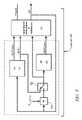
- FIG. 1is a schematic diagram of an exemplary powertrain, in accordance with the present disclosure
- FIG. 2is a schematic diagram of an exemplary architecture for a control system and powertrain, in accordance with the present disclosure
- FIG. 3illustrates a control system architecture for controlling and managing torque in a hybrid powertrain system, in accordance with the present disclosure
- FIG. 4is a schematic flow diagram illustrating the strategic optimization control scheme, in accordance with the present disclosure.
- FIG. 5is a schematic flow diagram illustrating several aspects of a strategic manager, in accordance with the present disclosure
- FIG. 6is a schematic flow diagram illustrating the strategic optimization scheme, in accordance with the present disclosure.
- FIGS. 7-9are schematic flow diagrams, in accordance with the present disclosure.
- FIG. 10is a datagraph, in accordance with the present disclosure.
- FIGS. 1 and 2depict an exemplary electro-mechanical hybrid powertrain system.
- the exemplary electro-mechanical hybrid powertrain system in accordance with the present disclosureis depicted in FIG. 1 , comprising a two-mode, compound-split, electro-mechanical hybrid transmission 10 operatively connected to an engine 14 and torque generating machines comprising first and second electric machines (‘MG-A’) 56 and (‘MG-B’) 72 .
- the engine 14 and first and second electric machines 56 and 72each generate mechanical power which can be transferred to the transmission 10 .
- the power generated by the engine 14 and the first and second electric machines 56 and 72 and transferred to the transmission 10is described in terms of input and motor torques, referred to herein as T I , T A , and T B respectively, and speed, referred to herein as N I , N A , and N B , respectively.
- the exemplary engine 14comprises a multi-cylinder internal combustion engine selectively operative in several states to transfer torque to the transmission 10 via an input shaft 12 , and can be either a spark-ignition or a compression-ignition engine.
- the engine 14includes a crankshaft (not shown) operatively coupled to the input shaft 12 of the transmission 10 .
- a rotational speed sensor 11monitors rotational speed of the input shaft 12 .
- Power output from the engine 14comprising rotational speed and engine torque, can differ from the input speed N I and the input torque T I to the transmission 10 due to placement of torque-consuming components on the input shaft 12 between the engine 14 and the transmission 10 , e.g., a hydraulic pump (not shown) and/or a torque management device (not shown).
- the exemplary transmission 10comprises three planetary-gear sets 24 , 26 and 28 , and four selectively engageable torque-transferring devices, i.e., clutches C 1 70 , C 2 62 , C 3 73 , and C 4 75 .
- clutchesrefer to any type of friction torque transfer device including single or compound plate clutches or packs, band clutches, and brakes, for example.
- a hydraulic control circuit 42preferably controlled by a transmission control module (hereafter ‘TCM’) 17 , is operative to control clutch states.
- Clutches C 2 62 and C 4 75preferably comprise hydraulically-applied rotating friction clutches.
- Clutches C 1 70 and C 3 73preferably comprise hydraulically-controlled stationary devices that can be selectively grounded to a transmission case 68 .
- Each of the clutches C 1 70 , C 2 62 , C 3 73 , and C 4 75is preferably hydraulically applied, selectively receiving pressurized hydraulic fluid via the hydraulic control circuit 42 .
- the first and second electric machines 56 and 72preferably comprise three-phase AC machines, each including a stator (not shown) and a rotor (not shown), and respective resolvers 80 and 82 .
- the motor stator for each machineis grounded to an outer portion of the transmission case 68 , and includes a stator core with coiled electrical windings extending therefrom.
- the rotor for the first electric machine 56is supported on a hub plate gear that is operatively attached to shaft 60 via the second planetary gear set 26 .
- the rotor for the second electric machine 72is fixedly attached to a sleeve shaft hub 66 .
- Each of the resolvers 80 and 82preferably comprises a variable reluctance device including a resolver stator (not shown) and a resolver rotor (not shown).
- the resolvers 80 and 82are appropriately positioned and assembled on respective ones of the first and second electric machines 56 and 72 .
- Stators of respective ones of the resolvers 80 and 82are operatively connected to one of the stators for the first and second electric machines 56 and 72 .
- the resolver rotorsare operatively connected to the rotor for the corresponding first and second electric machines 56 and 72 .
- Each of the resolvers 80 and 82is signally and operatively connected to a transmission power inverter control module (hereafter ‘TPIM’) 19 , and each senses and monitors rotational position of the resolver rotor relative to the resolver stator, thus monitoring rotational position of respective ones of first and second electric machines 56 and 72 . Additionally, the signals output from the resolvers 80 and 82 are interpreted to provide the rotational speeds for first and second electric machines 56 and 72 , i.e., N A and N B , respectively.
- TPIMtransmission power inverter control module
- the transmission 10includes an output member 64 , e.g. a shaft, which is operably connected to a driveline 90 for a vehicle (not shown), to provide output power to the driveline 90 that is transferred to vehicle wheels 93 , one of which is shown in FIG. 1 .
- the output power at the output member 64is characterized in terms of an output rotational speed N O and an output torque T O .
- a transmission output speed sensor 84monitors rotational speed and rotational direction of the output member 64 .
- Each of the vehicle wheels 93is preferably equipped with a friction brake 94 and a sensor (not shown) adapted to monitor wheel speed, the output of which is monitored by a control module of a distributed control module system described with respect to FIG. 2 , to determine vehicle speed, and absolute and relative wheel speeds for braking control, traction control, and vehicle acceleration management.
- the input torque from the engine 14 and the motor torques from the first and second electric machines 56 and 72(T I , T A , and T B respectively) are generated as a result of energy conversion from fuel or electrical potential stored in an electrical energy storage device (hereafter ‘ESD’) 74 .
- the ESD 74is high voltage DC-coupled to the TPIM 19 via DC transfer conductors 27 .
- the transfer conductors 27include a contactor switch 38 . When the contactor switch 38 is closed, under normal operation, electric current can flow between the ESD 74 and the TPIM 19 . When the contactor switch 38 is opened electric current flow between the ESD 74 and the TPIM 19 is interrupted.
- the TPIM 19transmits electrical power to and from the first electric machine 56 by transfer conductors 29 , and the TPIM 19 similarly transmits electrical power to and from the second electric machine 72 by transfer conductors 31 to meet the torque commands for the first and second electric machines 56 and 72 in response to the motor torque commands T A and T B . Electrical current is transmitted to and from the ESD 74 in accordance with whether the ESD 74 is being charged or discharged.
- the TPIM 19includes the pair of power inverters (not shown) and respective motor control modules (not shown) configured to receive the motor torque commands and control inverter states therefrom for providing motor drive or regeneration functionality to meet the commanded motor torques T A and T B .
- the power inverterscomprise known complementary three-phase power electronics devices, and each includes a plurality of insulated gate bipolar transistors (not shown) for converting DC power from the ESD 74 to AC power for powering respective ones of the first and second electric machines 56 and 72 , by switching at high frequencies.
- the insulated gate bipolar transistorsform a switch mode power supply configured to receive control commands. There is typically one pair of insulated gate bipolar transistors for each phase of each of the three-phase electric machines.
- the three-phase invertersreceive or supply DC electric power via DC transfer conductors 27 and transform it to or from three-phase AC power, which is conducted to or from the first and second electric machines 56 and 72 for operation as motors or generators via transfer conductors 29 and 31 respectively.
- FIG. 2is a schematic block diagram of the distributed control module system.
- the elements described hereinaftercomprise a subset of an overall vehicle control architecture, and provide coordinated system control of the exemplary hybrid powertrain described in FIG. 1 .
- the distributed control module systemsynthesizes pertinent information and inputs, and executes algorithms to control various actuators to meet control objectives, including objectives related to fuel economy, emissions, performance, drivability, and protection of hardware, including batteries of ESD 74 and the first and second electric machines 56 and 72 .
- the distributed control module systemincludes an engine control module (hereafter ‘ECM’) 23 , the TCM 17 , a battery pack control module (hereafter ‘BPCM’) 21 , and the TPIM 19 .
- ECMengine control module
- BPCMbattery pack control module
- a hybrid control module (hereafter ‘HCP’) 5provides supervisory control and coordination of the ECM 23 , the TCM 17 , the BPCM 21 , and the TPIM 19 .
- a user interface (‘UI’) 13is operatively connected to a plurality of devices through which a vehicle operator controls or directs operation of the electro-mechanical hybrid powertrain system.
- the devicesinclude an accelerator pedal 113 (‘AP’), an operator brake pedal 112 (‘BP’), a transmission gear selector 114 (‘PRNDL’), and a vehicle speed cruise control (not shown).
- the transmission gear selector 114may have a discrete number of operator-selectable positions, including the rotational direction of the output member 64 to enable one of a forward and a reverse direction.
- the aforementioned control modulescommunicate with other control modules, sensors, and actuators via a local area network (hereafter ‘LAN’) bus 6 .
- the LAN bus 6allows for structured communication of states of operating parameters and actuator command signals between the various control modules.
- the specific communication protocol utilizedis application-specific.
- the LAN bus 6 and appropriate protocolsprovide for robust messaging and multi-control module interfacing between the aforementioned control modules, and other control modules providing functionality including e.g., antilock braking, traction control, and vehicle stability.
- Multiple communications busesmay be used to improve communications speed and provide some level of signal redundancy and integrity. Communication between individual control modules can also be effected using a direct link, e.g., a serial peripheral interface (‘SPI’) bus (not shown).
- SPIserial peripheral interface
- the HCP 5provides supervisory control of the hybrid powertrain, serving to coordinate operation of the ECM 23 , TCM 17 , TPIM 19 , and BPCM 21 . Based upon various input signals from the user interface 13 and the hybrid powertrain, including the ESD 74 , the HCP 5 determines an operator torque request, an output torque command, an engine input torque command, clutch torque(s) for the applied torque-transfer clutches C 1 70 , C 2 62 , C 3 73 , C 4 75 of the transmission 10 , and the motor torque commands T A and T B for the first and second electric machines 56 and 72 .
- the ECM 23is operatively connected to the engine 14 , and functions to acquire data from sensors and control actuators of the engine 14 over a plurality of discrete lines, shown for simplicity as an aggregate bi-directional interface cable 35 .
- the ECM 23receives the engine input torque command from the HCP 5 .
- the ECM 23determines the actual engine input torque, T I , provided to the transmission 10 at that point in time based upon monitored engine speed and load, which is communicated to the HCP 5 .
- the ECM 23monitors input from the rotational speed sensor 11 to determine the engine input speed to the input shaft 12 , which translates to the transmission input speed, N I .
- the ECM 23monitors inputs from sensors (not shown) to determine states of other engine operating parameters including, e.g., a manifold pressure, engine coolant temperature, ambient air temperature, and ambient pressure.
- the engine loadcan be determined, for example, from the manifold pressure, or alternatively, from monitoring operator input to the accelerator pedal 113 .
- the ECM 23generates and communicates command signals to control engine actuators, including, e.g., fuel injectors, ignition modules, and throttle control modules, none of which are shown.
- the TCM 17is operatively connected to the transmission 10 and monitors inputs from sensors (not shown) to determine states of transmission operating parameters.
- the TCM 17generates and communicates command signals to control the transmission 10 , including controlling the hydraulic circuit 42 .
- Inputs from the TCM 17 to the HCP 5include estimated clutch torques for each of the clutches, i.e., C 1 70 , C 2 62 , C 3 73 , and C 4 75 , and rotational output speed, N O , of the output member 64 .
- Other actuators and sensorsmay be used to provide additional information from the TCM 17 to the HCP 5 for control purposes.
- the TCM 17monitors inputs from pressure switches (not shown) and selectively actuates pressure control solenoids (not shown) and shift solenoids (not shown) of the hydraulic circuit 42 to selectively actuate the various clutches C 1 70 , C 2 62 , C 3 73 , and C 4 75 to achieve various transmission operating range states, as described hereinbelow.
- the BPCM 21is signally connected to sensors (not shown) to monitor the ESD 74 , including states of electrical current and voltage parameters, to provide information indicative of parametric states of the batteries of the ESD 74 to the HCP 5 .
- the parametric states of the batteriespreferably include battery state-of-charge, battery voltage, battery temperature, and available battery power, referred to as a range P BAT — MIN to P BAT — MAX .
- a brake control module (hereafter ‘BrCM’) 22is operatively connected to friction brakes 94 on each of the vehicle wheels 93 .
- the BrCM 22monitors the operator input to the brake pedal 112 and generates control signals to control the friction brakes 94 and sends a control signal to the HCP 5 to operate the first and second electric machines 56 and 72 based thereon.
- Each of the control modules ECM 23 , TCM 17 , TPIM 19 , BPCM 21 , and BrCM 22is preferably a general-purpose digital computer comprising a microprocessor or central processing unit, storage mediums comprising read only memory (‘ROM’), random access memory (‘RAM’), electrically programmable read only memory (‘EPROM’), a high speed clock, analog to digital (‘A/D’) and digital to analog (‘D/A’) circuitry, and input/output circuitry and devices (‘I/O’) and appropriate signal conditioning and buffer circuitry.
- Each of the control moduleshas a set of control algorithms, comprising resident program instructions and calibrations stored in one of the storage mediums and executed to provide the respective functions of each computer.
- control algorithmsare executed during preset loop cycles such that each algorithm is executed at least once each loop cycle.
- Algorithms stored in the non-volatile memory devicesare executed by one of the central processing units to monitor inputs from the sensing devices and execute control and diagnostic routines to control operation of the actuators, using preset calibrations.
- Loop cyclesare executed at regular intervals, for example each 3.125, 6.25, 12.5, 25 and 100 milliseconds during ongoing operation of the hybrid powertrain.
- algorithmsmay be executed in response to the occurrence of an event.
- the exemplary hybrid powertrainselectively operates in one of several states that can be described in terms of engine states comprising one of an engine-on state (‘ON’) and an engine-off state (‘OFF’), and transmission operating range states comprising a plurality of fixed gears and continuously variable operating modes, described with reference to Table 1, below.
- engine statescomprising one of an engine-on state (‘ON’) and an engine-off state (‘OFF’)
- transmission operating range statescomprising a plurality of fixed gears and continuously variable operating modes, described with reference to Table 1, below.
- Each of the transmission operating range statesis described in the table and indicates which of the specific clutches C 1 70 , C 2 62 , C 3 73 , and C 4 75 are applied for each of the operating range states.
- a first continuously variable modei.e., EVT Mode 1 , or M 1
- the engine statecan be one of ON (‘M 1 _Eng_On’) or OFF (‘M 1 _Eng_Off’).
- a second continuously variable modei.e., EVT Mode 2 , or M 2 , is selected by applying clutch C 2 62 only to connect the shaft 60 to the carrier of the third planetary gear set 28 .
- the engine statecan be one of ON (‘M 2 _Eng_On’) or OFF (‘M 2 _Eng_Off’).
- RPMrevolutions per minute
- a fixed gear operationprovides a fixed ratio operation of input-to-output speed of the transmission 10 , i.e., N I /N O .
- a first fixed gear operation(‘G 1 ’) is selected by applying clutches C 1 70 and C 4 75 .
- a second fixed gear operation(‘G 2 ’) is selected by applying clutches C 1 70 and C 2 62 .
- a third fixed gear operation(‘G 3 ’) is selected by applying clutches C 2 62 and C 4 75 .
- a fourth fixed gear operation (‘G 4 ’)is selected by applying clutches C 2 62 and C 3 73 .
- the fixed ratio operation of input-to-output speedincreases with increased fixed gear operation due to decreased gear ratios in the planetary gears 24 , 26 , and 28 .
- the rotational speeds of the first and second electric machines 56 and 72 , N A and N B respectively,are dependent on internal rotation of the mechanism as defined by the clutching and are proportional to the input speed measured at the input shaft 12 .
- the HCP 5 and one or more of the other control modulesdetermine torque commands to control the torque generative devices comprising the engine 14 and the first and second electric machines 56 and 72 to meet the operator torque request at the output member 64 and transferred to the driveline 90 .
- the HCP 5determines the operator torque request, a commanded output torque from the transmission 10 to the driveline 90 , the input torque from the engine 14 , clutch torques for the torque-transfer clutches C 1 70 , C 2 62 , C 3 73 , C 4 75 of the transmission 10 ; and the motor torques for the first and second electric machines 56 and 72 , respectively, as is described hereinbelow.
- Final vehicle accelerationcan be affected by other factors including, e.g., road load, road grade, and vehicle mass.
- the engine state and the transmission operating range stateare determined based upon operating characteristics of the hybrid powertrain. This includes the operator torque request communicated through the accelerator pedal 113 and brake pedal 112 to the user interface 13 as previously described.
- the transmission operating range state and the engine statemay be predicated on a hybrid powertrain torque demand caused by a command to operate the first and second electric machines 56 and 72 in an electrical energy generating mode or in a torque generating mode.
- the transmission operating range state and the engine statecan be determined by an optimization algorithm or routine which determines optimum system efficiency based upon operator demand for power, battery state of charge, and energy efficiencies of the engine 14 and the first and second electric machines 56 and 72 .
- the control systemmanages torque inputs from the engine 14 and the first and second electric machines 56 and 72 based upon an outcome of the executed optimization routine, and system efficiencies are optimized thereby, to manage fuel economy and battery charging. Furthermore, operation can be determined based upon a fault in a component or system.
- the HCP 5monitors the torque-generative devices, and determines the power output from the transmission 10 at output member 64 that is required to meet the operator torque request while meeting other powertrain operating demands, e.g., charging the ESD 74 .
- the ESD 74 and the first and second electric machines 56 and 72are electrically-operatively coupled for power flow therebetween.
- the engine 14 , the first and second electric machines 56 and 72 , and the electro-mechanical transmission 10are mechanically-operatively coupled to transfer power therebetween to generate a power flow to the output member 64 .
- FIG. 3shows a control system architecture for controlling and managing signal flow in a hybrid powertrain system having multiple torque generative devices, described hereinbelow with reference to the hybrid powertrain system of FIGS. 1 and 2 , and residing in the aforementioned control modules in the form of executable algorithms and calibrations.
- the control system architectureis applicable to alternative hybrid powertrain systems having multiple torque generative devices, including, e.g., a hybrid powertrain system having an engine and a single electric machine, a hybrid powertrain system having an engine and multiple electric machines.
- the hybrid powertrain systemcan utilize non-electric torque-generative machines and energy storage systems, e.g., hydraulic-mechanical hybrid transmissions (not shown).
- the operator inputs to the accelerator pedal 113 and the brake pedal 112are monitored to determine the operator torque request.
- the operator inputs to the accelerator pedal 113 and the brake pedal 112comprise individually determinable operator torque request inputs including an immediate accelerator output torque request (‘Output Torque Request Accel Immed’), a predicted accelerator output torque request (‘Output Torque Request Accel Prdtd’), an immediate brake output torque request (‘Output Torque Request Brake Immed’), a predicted brake output torque request (‘Output Torque Request Brake Prdtd’) and an axle torque response type (‘Axle Torque Response Type’).
- the term ‘accelerator’refers to an operator request for forward propulsion preferably resulting in increasing vehicle speed over the present vehicle speed, when the operator selected position of the transmission gear selector 114 commands operation of the vehicle in the forward direction.
- the terms ‘deceleration’ and ‘brake’refer to an operator request preferably resulting in decreasing vehicle speed from the present vehicle speed.
- the immediate accelerator output torque request, the predicted accelerator output torque request, the immediate brake output torque request, the predicted brake output torque request, and the axle torque response typeare individual inputs to the control system. Additionally, operation of the engine 14 and the transmission 10 are monitored to determine the input speed (‘Ni’) and the output speed (‘No’).
- the immediate accelerator output torque requestis determined based upon a presently occurring operator input to the accelerator pedal 113 , and comprises a request to generate an immediate output torque at the output member 64 preferably to accelerate the vehicle.
- the predicted accelerator output torque requestis determined based upon the operator input to the accelerator pedal 113 and comprises an optimum or preferred output torque at the output member 64 .
- the predicted accelerator output torque requestis preferably equal to the immediate accelerator output torque request during normal operating conditions, e.g., when any one of antilock braking, traction control, or vehicle stability is not being commanded. When any one of antilock braking, traction control or vehicle stability is being commanded the predicted accelerator output torque request remains the preferred output torque with the immediate accelerator output torque request being decreased in response to output torque commands related to the antilock braking, traction control, or vehicle stability control.
- the immediate brake output torque requestis determined based upon a presently occurring operator input to the brake pedal 112 , and comprises a request to generate an immediate output torque at the output member 64 to effect a reactive torque with the driveline 90 which preferably decelerates the vehicle.
- the predicted brake output torque requestcomprises an optimum or preferred brake output torque at the output member 64 in response to an operator input to the brake pedal 112 subject to a maximum brake output torque generated at the output member 64 allowable regardless of the operator input to the brake pedal 112 .
- the maximum brake output torque generated at the output member 64is limited to ⁇ 0.2 g.
- the predicted brake output torque requestcan be phased out to zero when vehicle speed approaches zero regardless of the operator input to the brake pedal 112 .
- the predicted brake output torque requestWhen commanded by the operator, there can be operating conditions under which the predicted brake output torque request is set to zero, e.g., when the operator setting to the transmission gear selector 114 is set to a reverse gear, and when a transfer case (not shown) is set to a four-wheel drive low range.
- a strategic control scheme (‘Strategic Control’) 310determines a preferred input speed (‘Ni_Des’) and a preferred engine state and transmission operating range state (‘Hybrid Range State Des’) based upon the output speed and the operator torque request and based upon other operating parameters of the hybrid powertrain, including battery power limits and response limits of the engine 14 , the transmission 10 , and the first and second electric machines 56 and 72 .
- the predicted accelerator output torque request and the predicted brake output torque requestare input to the strategic control scheme 310 .
- the strategic control scheme 310is preferably executed by the HCP 5 during each 100 ms loop cycle and each 25 ms loop cycle.
- the desired operating range state for the transmission 10 and the desired input speed from the engine 14 to the transmission 10are inputs to the shift execution and engine start/stop control scheme 320 .
- the shift execution and engine start/stop control scheme 320commands changes in the transmission operation (‘Transmission Commands’) including changing the operating range state based upon the inputs and operation of the powertrain system. This includes commanding execution of a change in the transmission operating range state if the preferred operating range state is different from the present operating range state by commanding changes in application of one or more of the clutches C 1 70 , C 2 62 , C 3 73 , and C 4 75 and other transmission commands.
- the present operating range state(‘Hybrid Range State Actual’) and an input speed profile (‘Ni_Prof’) can be determined.
- the input speed profileis an estimate of an upcoming input speed and preferably comprises a scalar parametric value that is a targeted input speed for the forthcoming loop cycle.
- the engine operating commands and the operator torque requestare based upon the input speed profile during a transition in the operating range state of the transmission.
- a tactical control scheme (‘Tactical Control and Operation’) 330is executed during one of the control loop cycles to determine engine commands (‘Engine Commands’) for operating the engine 14 , including a preferred input torque from the engine 14 to the transmission 10 based upon the output speed, the input speed, and the operator torque request comprising the immediate accelerator output torque request, the predicted accelerator output torque request, the immediate brake output torque request, the predicted brake output torque request, the axle torque response type, and the present operating range state for the transmission.
- the engine commandsalso include engine states including one of an all-cylinder operating state and a cylinder deactivation operating state wherein a portion of the engine cylinders are deactivated and unfueled, and engine states including one of a fueled state and a fuel cutoff state.
- An engine commandcomprising the preferred input torque of the engine 14 and the present input torque (‘Ti’) reacting between the engine 14 and the input member 12 are preferably determined in the ECM 23 .
- An output and motor torque determination scheme (‘Output and Motor Torque Determination’) 340is executed to determine the preferred output torque from the powertrain (‘To_cmd’). This includes determining motor torque commands (‘T A ’, ‘T B ’) to transfer a net commanded output torque to the output member 64 of the transmission 10 that meets the operator torque request, by controlling the first and second electric machines 56 and 72 in this embodiment.
- the immediate accelerator output torque request, the immediate brake output torque request, the present input torque from the engine 14 and the estimated applied clutch torque(s), the present operating range state of the transmission 10 , the input speed, the input speed profile, and the axle torque response typeare inputs.
- the output and motor torque determination scheme 340executes to determine the motor torque commands during each iteration of one of the loop cycles.
- the output and motor torque determination scheme 340includes algorithmic code which is regularly executed during the 6.25 ms and 12.5 ms loop cycles to determine the preferred motor torque commands.
- the hybrid powertrainis controlled to transfer the output torque to the output member 64 to react with the driveline 90 to generate tractive torque at wheel(s) 93 to forwardly propel the vehicle in response to the operator input to the accelerator pedal 113 when the operator selected position of the transmission gear selector 114 commands operation of the vehicle in the forward direction.
- the hybrid powertrainis controlled to transfer the output torque to the output member 64 to react with the driveline 90 to generate tractive torque at wheel(s) 93 to propel the vehicle in a reverse direction in response to the operator input to the accelerator pedal 113 when the operator selected position of the transmission gear selector 114 commands operation of the vehicle in the reverse direction.
- propelling the vehicleresults in vehicle acceleration so long as the output torque is sufficient to overcome external loads on the vehicle, e.g., due to road grade, aerodynamic loads, and other loads.
- N A N B ][ A 1 ] ⁇ [ N I N O ] [ 1 ]
- N Icomprises the input speed from the engine 14
- N Ois the transmission output speed
- N A and N Bare the operating speeds for first and second electric machines 56 and 72
- a 1is a 2 ⁇ 2 matrix of parametric values based upon hardware gear and shaft interconnections determined for the specific application, and for the specific operating range state, i.e., M 1 or M 2 .
- first and second electric machines 56 and 72The torque relationship between first and second electric machines 56 and 72 , the input speed N I , the output speed N O , input torque, and motor torque is defined as:
- T A T B[ a 11 a 12 a 21 a 22 ] ⁇ [ T I T O ] + [ b 11 b 12 b 21 b 22 ] ⁇ [ N I N O ] [ 2 ]
- T Iis the input torque from the engine 14
- T Ois the transmission output torque
- T A and T Bare the motor torques for first and second electric machines 56 and 72 and a 11 , a 12 , a 21 , a 22 , b 11 , b 12 , b 21 , and b 22 are scalar values of known parametric values based upon hardware gear and shaft interconnections determined for the specific application and for the specific continuously variable operating range state, i.e., M 1 or M 2 .
- the speed relationship between the first and second electric machines 56 and 72 , the engine input speed N I and the transmission output speed N Ois defined as shown in the equation below:
- N I N A N B ][ B 1 ] * N O [ 3 ]
- N Icomprises the input speed from engine 14
- N Ois the transmission output speed
- N A and N Bare the operating speeds for first and second electric machines 56 and 72
- B Iis a 1 ⁇ 3 matrix of known parametric values based upon hardware gear and shaft interconnections determined for the specific application, and for the specific operating range state.
- N Ifor the engine 14 and N A and N B can be determined.
- first and second electric machines 56 and 72The torque relationships between first and second electric machines 56 and 72 , input torque, and motor torque are as defined in Eq. 4 below:
- T O[ a b c d e ] * [ T I T A T B N i N o ] [ 4 ]
- T Iis the input torque from engine 14
- T Ois the transmission output torque, i.e., the requested output torque
- T O — REQis the motor torques for first and second electric machines 56 and 72
- a, b, c, d, and eare known parametric values based upon hardware gear and shaft interconnections determined for the specific application, and for the specific fixed gear operating ranges state.
- compensating for the inertial effectscomprises including the rotational acceleration of the input member 12 in Eq. 4.
- Including the rotational acceleration of the input member 12the torque relationships between first and second electric machines 56 and 72 , input torque, and output torque are defined as:
- T O[ a b c d e f ] * [ T I T A T B N i N o N . I ] [ 6 ] wherein ⁇ dot over (N) ⁇ I represents acceleration of the input member 12 , and a, b, c, d, e, and f are known parametric values based upon hardware gear and shaft interconnections determined for the specific application, and for the specific operating range state.
- FIG. 4details signal flow in the strategic optimization control scheme 310 , which includes a strategic manager 220 , an operating range state analyzer 260 , and a state stabilization and arbitration block 280 to determine the preferred input speed (‘Ni_Des’) and the preferred transmission operating range state (‘Hybrid Range State Des’).
- the strategic manager (‘Strategic Manager’) 220monitors the output speed N O , the predicted accelerator output torque request (‘Output Torque Request Accel Prdtd’), the predicted brake output torque request (‘Output Torque Request Brake Prdtd’), and available battery power P BAT — MIN to P BAT — MAX .
- the strategic manager 220determines which of the transmission operating range states are allowable, and determines output torque requests comprising a strategic accelerator output torque request (‘Output Torque Request Accel Strategic’) and a strategic net output torque request (‘Output Torque Request Net Strategic’), all of which are input the operating range state analyzer 260 along with system inputs (‘System Inputs’) and power cost inputs (‘Power Cost Inputs’).
- the operating range state analyzer 260generates a preferred power cost (‘P*cost’) and associated input speed (‘N*i’) for each of the allowable operating range states based upon the operator torque requests, the system inputs, the available battery power and the power cost inputs.
- the preferred power costs and associated input speeds for the allowable operating range statesare input to the state stabilization and arbitration block 280 which selects the preferred operating range state and preferred input speed based thereon.
- FIG. 5shows a functional block diagram detailing an operation of the strategic manager 220 .
- an input acceleration algorithm‘Calc Nidot (Modes)’
- a torque offset algorithm‘Precalc TrqOffsets’
- a strategic manager algorithm223
- Inputs to the strategic manager algorithminclude the predicted accelerator output torque request (‘Output Torque Request Accel Prdtd’), the predicted brake output torque request (‘Output Torque Request Brake Prdtd’), and the output speed (‘N O ’).
- the strategic manager algorithm 223determines a strategic output speed, the strategic torque request, and a rotational output acceleration of the output member 64 .
- the input acceleration algorithm 221inputs the strategic output speed (‘No Strategic’), the strategic torque request (‘To Req Strategic’), and the rotational output acceleration (‘Nodot’).
- the input acceleration algorithm 221determines a rotational input acceleration (‘Nidot’) of the input member 12 for the continuously variable modes M 1 and M 2 .
- the torque offset algorithm 222determines a torque offset for each of the first and second electrical machines 56 and 72 (‘Ta offset’ and ‘Tb offset’) for operating in one of the continuously variable modes and an output torque offset for the operating in one of the fixed gears (‘To offset’).
- the torque offsetsare preferably determined in the strategic manager 220 for increased computational efficiency.
- the torque offsetsare output to the operating range state analyzer 260 as described hereinbelow.
- the strategic output speedcomprises a predicted output speed occurring at a future time instant.
- One method for determining the predicted output speedcomprises determining a time-based derivative of the monitored output speed No, multiplying the resultant with an elapsed time from the present to the future time instant and adding the resultant to the monitored output speed No.
- the strategic torque requestis preferably a predicted operator torque request for a future time instant and is preferably based upon the predicted accelerator output torque request.
- the rotational output accelerationis preferably determined based upon the monitored output speed. The rotational output acceleration can be determined by calculating a time-based derivative of the output speed N O and adding the resultant to the monitored output speed No.
- motor torque offsetsare determined for each of the first and second electrical machines 56 and 72 .
- the motor torque offsetsare determined based upon the rotational output acceleration, the rotational input acceleration, and the strategic output speed.
- T B — OFFSETb 22 N O +c 21 ⁇ dot over (N) ⁇ I +c 22 ⁇ dot over (N) ⁇ O [8] wherein
- an output torque offsetis determined.
- the torque offsetis determined based upon the rotational output acceleration, the strategic output speed, and the input speed N I .
- FIG. 6shows the operating range state analyzer 260 .
- the operating range state analyzer 260executes searches in each candidate operating range state comprising the allowable ones of the operating range states, including M 1 ( 262 ), M 2 ( 264 ), G 1 ( 270 ), G 2 ( 272 ), G 3 ( 274 ), and G 4 ( 276 ) to determine preferred operation of the torque actuators, i.e., the engine 14 and the first and second electric machines 56 and 72 in this embodiment.
- the preferred operationpreferably comprises a minimum power cost for operating the hybrid powertrain system and an associated engine input for operating in the candidate operating range state in response to the operator torque request.
- the associated engine inputcomprises at least one of a preferred engine input speed (‘Ni*’), a preferred engine input power (‘Pi*’), and a preferred engine input torque (‘Ti*’) that is responsive to and preferably meets the operator torque request.
- the operating range state analyzer 260evaluates M 1 -Engine Off ( 264 ) and M 2 -Engine Off ( 266 ) to determine a preferred cost (‘P*cost’) for operating the powertrain system responsive to and preferably meeting the operator torque request when the engine 14 is in the engine-off state.
- FIG. 7schematically shows signal flow for the 1-dimension search scheme 610 .
- a range of one controllable inputin this embodiment comprising minimum and maximum input torques (‘TiMin/Max’)
- TiMin/Maxminimum and maximum input torques
- the 1-D search engine 415iteratively generates candidate input torques (‘Ti(j)’) which range between the minimum and maximum input torques, each which is input to an optimization function (‘Opt To/Ta/Tb’) 440 , for n search iterations.
- Other inputs to the optimization function 440include system inputs preferably comprise parametric states for battery power, clutch torques, electric motor operation, transmission and engine operation, the specific operating range state and the operator torque request.
- the optimization function 440determines transmission operation comprising an output torque, motor torques, and associated battery powers (‘To(j), Ta(j), Tb(j), Pbat(j), Pa(j), Pb(j)’) associated with the candidate input torque based upon the system inputs in response to the operator torque request for the candidate operating range state.
- FIG. 8shows the preferred operation in each of continuously variable modes M 1 and M 2 executed in blocks 262 and 264 of the operating range state analyzer 260 .
- Thisincludes executing a 2-dimensional search scheme 620 , shown with reference to FIGS. 7 and 9 , in conjunction with executing a 1-dimensional search using the 1-dimensional search scheme 610 based upon a previously determined input speed which can be arbitrated (‘Input Speed Stabilization and Arbitration’) 615 to determine preferred costs (‘P*cost’) and associated preferred input speeds (‘N*i’) for the operating range states.
- the 2-dimensional search scheme 620determines a a first preferred cost (‘2D P*cost’) and an associated first preferred input speed (‘2D N*I’).
- the first preferred input speedis input to the 2-dimensional search scheme 620 and to an adder 612 .
- the adder 612sums the first preferred input speed and a time-rate change in the input speed (‘N I — DOT ’) multiplied by a predetermined time period (‘dt’).
- the resultantis input to a switch 605 along with the first preferred input speed determined by the 2-dimensional search scheme 620 .
- the switch 605is controlled to input either the resultant from the adder 612 or the preferred input speed determined by the 2-dimensional search scheme 620 into the 1-dimensional search scheme 610 .
- the switch 605is controlled to input the preferred input speed determined by the 2-dimensional search scheme 620 into the 1-dimensional search scheme 610 (as shown) when the powertrain system is operating in a regenerative braking mode, e.g., when the operator torque request includes a request to generate an immediate output torque at the output member 64 to effect a reactive torque with the driveline 90 which preferably decelerates the vehicle.
- the switch 605is controlled to a second position (not shown) to input the resultant from the adder 612 when the operator torque request does not include regenerative braking.
- the 1-dimensional search scheme 610is executed to determine a second preferred cost (‘1D P*cost’) using the 1-dimensional search scheme 610 , which is input to the input speed stabilization and arbitration block 615 to select a final preferred cost and associated preferred input speed.
- FIG. 9schematically shows signal flow for the 2-dimension search scheme 620 .
- Ranges of two controllable inputsin this embodiment comprising minimum and maximum input speeds (‘NiMin/Max’) and minimum and maximum input powers (‘PiMin/Max’) are input to a 2-D search engine 410 .
- the two controllable inputscan comprise minimum and maximum input speeds and minimum and maximum input torques.
- the 2-D search engine 410iteratively generates candidate input speeds (‘Ni(j)’) and candidate input powers (‘Pi(j)’) which range between the minimum and maximum input speeds and powers.
- the candidate input poweris preferably converted to a candidate input torque (‘Ti(j)’) ( 412 ).
- Each candidate input speed (‘Ni(j)’) and candidate input torque (‘Ti(j)’)are input to an optimization function (‘Opt To/Ta/Tb’) 440 , for n search iterations.
- Other inputs to the optimization function 440include system inputs preferably comprising parametric states for battery power, clutch torques, electric motor operation, transmission and engine operation, the specific operating range state and the operator torque request.
- the optimization function 440determines transmission operation comprising an output torque, motor torques, and associated battery powers (‘To(j), Ta(j), Tb(j), Pbat(j), Pa(j), Pb(j)’) associated with the candidate input power and candidate input speed based upon the system inputs and the operating torque request for the candidate operating range state.
- Additional inputs into the optimization function 440include the motor torque offsets and the output torque offset.
- the optimization function 440determines the output torque for each candidate input speeds Ni(j) and candidate input torque Ti(j) based upon the output torque offset determined in the strategic manager 220 , motor torques, and known parametric values based upon hardware gear and shaft interconnections determined for the specific application, and for the specific operating range state.
- the output torquecan be determined based upon the following equation:
- the optimization function 440determines the output torque and motor torques for each candidate input speeds Ni(j) and candidate input powers Pi(j) based upon the motor torque offsets determined in the strategic manager 220 , the candidate input torque Ti(j), output torque, candidate input speed Ni(j), and known parametric values based upon hardware gear and shaft interconnections determined for the specific application, and for the specific operating range state.
- the output torque and motor torquesare determined based upon the following equation:
- the output torque (‘T O (j)’), motor torques (‘T A (j)’) and (‘T B (j)’), and associated battery powers and power cost inputsare input to a cost function 450 , which executes to determine a power cost (‘Pcost(j)’) for operating the powertrain at the candidate input power or candidate input torque and candidate input speed in response to the operator torque request in the candidate operating range state.
- the 1-D search engine 415iteratively generates candidate input torques over the range of input torques and determines the power costs associated therewith to identify a preferred input torque (‘Ti*’) and associated preferred power cost (‘P*cost’).
- the preferred input torquecomprises the candidate input torque within the range of input torques that results in a minimum power cost of the candidate operating range state, i.e., the preferred power cost.
- the 2-D search engine 410iteratively generates the candidate input powers and candidate input speeds over the range of input speeds and range of input powers and determines the power costs associated therewith to identify a preferred input power (‘Pi*’) and preferred input speed (‘Ni*’) and associated preferred cost (‘P*cost’).
- the preferred input power (‘Pi*’) and preferred input speed (‘Ni*’)comprises the candidate input power and candidate input speed that result in a minimum power cost for the candidate operating range state.
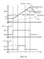
- FIG. 10graphically illustrates the input speed determined without compensating for inertial effects and a preferred input speed determined with compensating for inertial effect during transitions between G 1 and M 1 .
- compensating for inertial effectsincreases preferred input speed determinations for the fixed gear mode operating range states greater than preferred input speed determinations for the mode operating range states.
- the preferred input speed determinationsaffect power of the engine 14 , e.g., additional preferred input speed requires additional engine power.
- the additional power required to increase or decrease the engine input speed N Iaffects power cost determinations (‘Pcost’) for each operating range state.
- Pcostpower cost determinations
- motor torques T A and T Bare determined based upon the inertia effects resulting from inclusion of the acceleration terms ⁇ dot over (N) ⁇ I and ⁇ dot over (N) ⁇ O in the optimization function 440 additional power required to increase or decrease the engine input speed N I is compensated in the power cost determinations.
- the additional poweraffects a trajectory of the input speed N I based upon the operating range state selection.
- the power cost determinationsdo not account for the additional power required to increase or decrease the engine input speed N I .
- the operating range state selectionis based upon non-preferred power cost determinations thereby resulting in a trajectory of the input speed N I that is less efficient.
- inertia compensationincreases operating time in M 1 and decreases operating time in fixed gear mode operating range state G 1 based upon a higher calculated power cost for operating in G 1 thereby increasing the total powertrain system efficiency.
- the state stabilization and arbitration block 280selects a preferred transmission operating range state (‘Hybrid Range State Des’) which preferably is the transmission operating range state associated with the minimum preferred power cost for the allowed operating range states output from the operating range state analyzer 260 , taking into account factors related to arbitrating effects of changing the operating range state on the operation of the transmission to effect stable powertrain operation.
- the preferred input speed(‘Ni_Des’) is the engine input speed associated with the preferred engine input comprising the preferred engine input speed (‘Ni*’), the preferred engine input power (‘Pi*’), and the preferred engine input torque (‘Ti*’) that is responsive to and preferably meets the operator torque request for the selected preferred operating range state.
Landscapes
- Engineering & Computer Science (AREA)
- Chemical & Material Sciences (AREA)
- Combustion & Propulsion (AREA)
- Transportation (AREA)
- Mechanical Engineering (AREA)
- Automation & Control Theory (AREA)
- Electric Propulsion And Braking For Vehicles (AREA)
- Hybrid Electric Vehicles (AREA)
- Control Of Transmission Device (AREA)
Abstract
Description
| TABLE 1 | |||
| Engine | Transmission Operating | Applied | |
| Description | State | Range State | Clutches |
| M1_Eng_Off | EVT Mode | 1 | |||
| M1_Eng_On | EVT Mode | 1 | |||
| G1 | ON | ||||
| G2 | ON | Fixed Gear Ratio 2 | |||
| M2_Eng_Off | OFF | EVT Mode 2 | |||
| M2_Eng_On | ON | EVT Mode 2 | |||
| G3 | ON | Fixed Gear Ratio 3 | |||
| G4 | ON | Fixed Gear Ratio 4 | |||
wherein NIcomprises the input speed from the
wherein TIis the input torque from the
wherein NIcomprises the input speed from
wherein TIis the input torque from
wherein
- {dot over (N)}Irepresents acceleration of the
input member 12, - {dot over (N)}Orepresents acceleration of
output member 64, and - a11, a12, a21, a22, b11, b12, b21, b22c11, c12, c21, and c22are known parametric values based upon hardware gear and shaft interconnections determined for the specific application and for the specific operating range state, i.e., M1 or M2.
- {dot over (N)}Irepresents acceleration of the
wherein {dot over (N)}Irepresents acceleration of the
TA
wherein
- NOrepresents output speed,
- {dot over (N)}Irepresents input acceleration,
- {dot over (N)}Orepresents output acceleration, and
- b12, c11, and c12represent known parametric values based upon hardware gear and shaft interconnections determined for the specific application, and for the specific operating range state.
TB
wherein
- NOrepresents output speed,
- {dot over (N)}Irepresents input acceleration,
- {dot over (N)}Orepresents output acceleration, and
- b22, c21, and c22represent known parametric values based upon hardware gear and shaft interconnections determined for the specific application, and for the specific operating range state.
TOOffset=dNI+eNO+f{dot over (N)}I [9]
wherein
- d, e, and f represent known parametric values based upon hardware gear and shaft interconnections determined for the specific application, and for the specific operating range state.
wherein
- TA(j) represents motor torque for the first
electric machine 56, - TB(j) represents motor torque for the second
electric machine 72, - TI(j) represents engine input torque to the
transmission 10, - TO(j) is the output torque out of the
transmission 10, and - a, b, and c are known parametric values based upon hardware gear and shaft interconnections determined for the specific application and for the specific operating range state.
- TA(j) represents motor torque for the first
wherein
- TA(j) represents motor torque for the first
electric machine 56, - TB(j) represents motor torque for the second
electric machine 72, - TI(j) represents engine input torque to the
transmission 10, - TO(j) is the output torque out of the
transmission 10, - NI(j) represents input speed, and
- a11, a12, a21, a22, b11, b21are known parametric values based upon hardware gear and shaft interconnections determined for the specific application and for the specific operating range state.
- TA(j) represents motor torque for the first
Claims (21)
Priority Applications (3)
| Application Number | Priority Date | Filing Date | Title |
|---|---|---|---|
| US12/236,062US8118903B2 (en) | 2007-11-04 | 2008-09-23 | Method for preferential selection of modes and gear with inertia effects for a hybrid powertrain system |
| EP08019012AEP2070792B1 (en) | 2007-11-04 | 2008-10-30 | Method for preferential selection of modes and gear with inertia effects for a hybrid powertrain system |
| CN2008101898810ACN101519072B (en) | 2007-11-04 | 2008-11-04 | Method for preferential selection of modes and gear with inertia effects for a hybrid powertrain system |
Applications Claiming Priority (2)
| Application Number | Priority Date | Filing Date | Title |
|---|---|---|---|
| US98527107P | 2007-11-04 | 2007-11-04 | |
| US12/236,062US8118903B2 (en) | 2007-11-04 | 2008-09-23 | Method for preferential selection of modes and gear with inertia effects for a hybrid powertrain system |
Publications (2)
| Publication Number | Publication Date |
|---|---|
| US20090118075A1 US20090118075A1 (en) | 2009-05-07 |
| US8118903B2true US8118903B2 (en) | 2012-02-21 |
Family
ID=40588706
Family Applications (1)
| Application Number | Title | Priority Date | Filing Date |
|---|---|---|---|
| US12/236,062Active2030-08-31US8118903B2 (en) | 2007-11-04 | 2008-09-23 | Method for preferential selection of modes and gear with inertia effects for a hybrid powertrain system |
Country Status (3)
| Country | Link |
|---|---|
| US (1) | US8118903B2 (en) |
| EP (1) | EP2070792B1 (en) |
| CN (1) | CN101519072B (en) |
Families Citing this family (120)
| Publication number | Priority date | Publication date | Assignee | Title |
|---|---|---|---|---|
| US8390240B2 (en)* | 2007-08-06 | 2013-03-05 | GM Global Technology Operations LLC | Absolute position sensor for field-oriented control of an induction motor |
| US7867135B2 (en) | 2007-09-26 | 2011-01-11 | GM Global Technology Operations LLC | Electro-mechanical transmission control system |
| US8234048B2 (en)* | 2007-10-19 | 2012-07-31 | GM Global Technology Operations LLC | Method and system for inhibiting operation in a commanded operating range state for a transmission of a powertrain system |
| US9140337B2 (en)* | 2007-10-23 | 2015-09-22 | GM Global Technology Operations LLC | Method for model based clutch control and torque estimation |
| US8060267B2 (en)* | 2007-10-23 | 2011-11-15 | GM Global Technology Operations LLC | Method for controlling power flow within a powertrain system |
| US8187145B2 (en)* | 2007-10-25 | 2012-05-29 | GM Global Technology Operations LLC | Method and apparatus for clutch torque control in mode and fixed gear for a hybrid powertrain system |
| US8335623B2 (en)* | 2007-10-25 | 2012-12-18 | GM Global Technology Operations LLC | Method and apparatus for remediation of and recovery from a clutch slip event in a hybrid powertrain system |
| US8265821B2 (en)* | 2007-10-25 | 2012-09-11 | GM Global Technology Operations LLC | Method for determining a voltage level across an electric circuit of a powertrain |
| US8118122B2 (en)* | 2007-10-25 | 2012-02-21 | GM Global Technology Operations LLC | Method and system for monitoring signal integrity in a distributed controls system |
| US8296027B2 (en) | 2007-10-25 | 2012-10-23 | GM Global Technology Operations LLC | Method and apparatus to control off-going clutch torque during torque phase for a hybrid powertrain system |
| US8167773B2 (en) | 2007-10-26 | 2012-05-01 | GM Global Technology Operations LLC | Method and apparatus to control motor cooling in an electro-mechanical transmission |
| US8548703B2 (en) | 2007-10-26 | 2013-10-01 | GM Global Technology Operations LLC | Method and apparatus to determine clutch slippage in an electro-mechanical transmission |
| US9097337B2 (en) | 2007-10-26 | 2015-08-04 | GM Global Technology Operations LLC | Method and apparatus to control hydraulic line pressure in an electro-mechanical transmission |
| US8560191B2 (en) | 2007-10-26 | 2013-10-15 | GM Global Technology Operations LLC | Method and apparatus to control clutch pressures in an electro-mechanical transmission |
| US8204702B2 (en)* | 2007-10-26 | 2012-06-19 | GM Global Technology Operations LLC | Method for estimating battery life in a hybrid powertrain |
| US8406945B2 (en)* | 2007-10-26 | 2013-03-26 | GM Global Technology Operations LLC | Method and apparatus to control logic valves for hydraulic flow control in an electro-mechanical transmission |
| US7985154B2 (en)* | 2007-10-26 | 2011-07-26 | GM Global Technology Operations LLC | Method and apparatus to control hydraulic pressure for component lubrication in an electro-mechanical transmission |
| US8303463B2 (en)* | 2007-10-26 | 2012-11-06 | GM Global Technology Operations LLC | Method and apparatus to control clutch fill pressure in an electro-mechanical transmission |
| US8062174B2 (en)* | 2007-10-27 | 2011-11-22 | GM Global Technology Operations LLC | Method and apparatus to control clutch stroke volume in an electro-mechanical transmission |
| US8428816B2 (en)* | 2007-10-27 | 2013-04-23 | GM Global Technology Operations LLC | Method and apparatus for monitoring software and signal integrity in a distributed control module system for a powertrain system |
| US8099219B2 (en) | 2007-10-27 | 2012-01-17 | GM Global Technology Operations LLC | Method and apparatus for securing an operating range state mechanical transmission |
| US8244426B2 (en)* | 2007-10-27 | 2012-08-14 | GM Global Technology Operations LLC | Method and apparatus for monitoring processor integrity in a distributed control module system for a powertrain system |
| US8209098B2 (en)* | 2007-10-29 | 2012-06-26 | GM Global Technology Operations LLC | Method and apparatus for monitoring a transmission range selector in a hybrid powertrain transmission |
| US8095254B2 (en)* | 2007-10-29 | 2012-01-10 | GM Global Technology Operations LLC | Method for determining a power constraint for controlling a powertrain system |
| US8489293B2 (en)* | 2007-10-29 | 2013-07-16 | GM Global Technology Operations LLC | Method and apparatus to control input speed profile during inertia speed phase for a hybrid powertrain system |
| US8290681B2 (en)* | 2007-10-29 | 2012-10-16 | GM Global Technology Operations LLC | Method and apparatus to produce a smooth input speed profile in mode for a hybrid powertrain system |
| US8170762B2 (en) | 2007-10-29 | 2012-05-01 | GM Global Technology Operations LLC | Method and apparatus to control operation of a hydraulic pump for an electro-mechanical transmission |
| US8112194B2 (en)* | 2007-10-29 | 2012-02-07 | GM Global Technology Operations LLC | Method and apparatus for monitoring regenerative operation in a hybrid powertrain system |
| US8282526B2 (en)* | 2007-10-29 | 2012-10-09 | GM Global Technology Operations LLC | Method and apparatus to create a pseudo torque phase during oncoming clutch engagement to prevent clutch slip for a hybrid powertrain system |
| US8035324B2 (en)* | 2007-11-01 | 2011-10-11 | GM Global Technology Operations LLC | Method for determining an achievable torque operating region for a transmission |
| US8145375B2 (en)* | 2007-11-01 | 2012-03-27 | GM Global Technology Operations LLC | System constraints method of determining minimum and maximum torque limits for an electro-mechanical powertrain system |
| US8073602B2 (en)* | 2007-11-01 | 2011-12-06 | GM Global Technology Operations LLC | System constraints method of controlling operation of an electro-mechanical transmission with an additional constraint range |
| US7977896B2 (en) | 2007-11-01 | 2011-07-12 | GM Global Technology Operations LLC | Method of determining torque limit with motor torque and battery power constraints |
| US8556011B2 (en)* | 2007-11-01 | 2013-10-15 | GM Global Technology Operations LLC | Prediction strategy for thermal management and protection of power electronic hardware |
| US8133151B2 (en)* | 2007-11-02 | 2012-03-13 | GM Global Technology Operations LLC | System constraints method of controlling operation of an electro-mechanical transmission with an additional constraint |
| US8170764B2 (en) | 2007-11-02 | 2012-05-01 | GM Global Technology Operations LLC | Method and apparatus to reprofile input speed during speed during speed phase during constrained conditions for a hybrid powertrain system |
| US8847426B2 (en) | 2007-11-02 | 2014-09-30 | GM Global Technology Operations LLC | Method for managing electric power in a powertrain system |
| US8825320B2 (en)* | 2007-11-02 | 2014-09-02 | GM Global Technology Operations LLC | Method and apparatus for developing a deceleration-based synchronous shift schedule |
| US8224539B2 (en) | 2007-11-02 | 2012-07-17 | GM Global Technology Operations LLC | Method for altitude-compensated transmission shift scheduling |
| US8131437B2 (en)* | 2007-11-02 | 2012-03-06 | GM Global Technology Operations LLC | Method for operating a powertrain system to transition between engine states |
| US8121765B2 (en)* | 2007-11-02 | 2012-02-21 | GM Global Technology Operations LLC | System constraints method of controlling operation of an electro-mechanical transmission with two external input torque ranges |
| US8585540B2 (en) | 2007-11-02 | 2013-11-19 | GM Global Technology Operations LLC | Control system for engine torque management for a hybrid powertrain system |
| US8287426B2 (en)* | 2007-11-02 | 2012-10-16 | GM Global Technology Operations LLC | Method for controlling voltage within a powertrain system |
| US8200403B2 (en) | 2007-11-02 | 2012-06-12 | GM Global Technology Operations LLC | Method for controlling input torque provided to a transmission |
| US8121767B2 (en)* | 2007-11-02 | 2012-02-21 | GM Global Technology Operations LLC | Predicted and immediate output torque control architecture for a hybrid powertrain system |
| US8010247B2 (en) | 2007-11-03 | 2011-08-30 | GM Global Technology Operations LLC | Method for operating an engine in a hybrid powertrain system |
| US8224514B2 (en)* | 2007-11-03 | 2012-07-17 | GM Global Technology Operations LLC | Creation and depletion of short term power capability in a hybrid electric vehicle |
| US8204664B2 (en) | 2007-11-03 | 2012-06-19 | GM Global Technology Operations LLC | Method for controlling regenerative braking in a vehicle |
| US8155814B2 (en) | 2007-11-03 | 2012-04-10 | GM Global Technology Operations LLC | Method of operating a vehicle utilizing regenerative braking |
| US8135526B2 (en)* | 2007-11-03 | 2012-03-13 | GM Global Technology Operations LLC | Method for controlling regenerative braking and friction braking |
| US8296021B2 (en) | 2007-11-03 | 2012-10-23 | GM Global Technology Operations LLC | Method for determining constraints on input torque in a hybrid transmission |
| US8406970B2 (en) | 2007-11-03 | 2013-03-26 | GM Global Technology Operations LLC | Method for stabilization of optimal input speed in mode for a hybrid powertrain system |
| US8002667B2 (en)* | 2007-11-03 | 2011-08-23 | GM Global Technology Operations LLC | Method for determining input speed acceleration limits in a hybrid transmission |
| US8868252B2 (en)* | 2007-11-03 | 2014-10-21 | GM Global Technology Operations LLC | Control architecture and method for two-dimensional optimization of input speed and input power including search windowing |
| US8068966B2 (en) | 2007-11-03 | 2011-11-29 | GM Global Technology Operations LLC | Method for monitoring an auxiliary pump for a hybrid powertrain |
| US8285431B2 (en) | 2007-11-03 | 2012-10-09 | GM Global Technology Operations LLC | Optimal selection of hybrid range state and/or input speed with a blended braking system in a hybrid electric vehicle |
| US8260511B2 (en)* | 2007-11-03 | 2012-09-04 | GM Global Technology Operations LLC | Method for stabilization of mode and fixed gear for a hybrid powertrain system |
| US8346449B2 (en)* | 2007-11-04 | 2013-01-01 | GM Global Technology Operations LLC | Method and apparatus to provide necessary output torque reserve by selection of hybrid range state and input speed for a hybrid powertrain system |
| US8897975B2 (en)* | 2007-11-04 | 2014-11-25 | GM Global Technology Operations LLC | Method for controlling a powertrain system based on penalty costs |
| US8112206B2 (en) | 2007-11-04 | 2012-02-07 | GM Global Technology Operations LLC | Method for controlling a powertrain system based upon energy storage device temperature |
| US8126624B2 (en) | 2007-11-04 | 2012-02-28 | GM Global Technology Operations LLC | Method for selection of optimal mode and gear and input speed for preselect or tap up/down operation |
| US8204656B2 (en) | 2007-11-04 | 2012-06-19 | GM Global Technology Operations LLC | Control architecture for output torque shaping and motor torque determination for a hybrid powertrain system |
| US8214120B2 (en)* | 2007-11-04 | 2012-07-03 | GM Global Technology Operations LLC | Method to manage a high voltage system in a hybrid powertrain system |
| US8098041B2 (en) | 2007-11-04 | 2012-01-17 | GM Global Technology Operations LLC | Method of charging a powertrain |
| US8079933B2 (en) | 2007-11-04 | 2011-12-20 | GM Global Technology Operations LLC | Method and apparatus to control engine torque to peak main pressure for a hybrid powertrain system |
| US8067908B2 (en)* | 2007-11-04 | 2011-11-29 | GM Global Technology Operations LLC | Method for electric power boosting in a powertrain system |
| US8214093B2 (en)* | 2007-11-04 | 2012-07-03 | GM Global Technology Operations LLC | Method and apparatus to prioritize transmission output torque and input acceleration for a hybrid powertrain system |
| US8092339B2 (en)* | 2007-11-04 | 2012-01-10 | GM Global Technology Operations LLC | Method and apparatus to prioritize input acceleration and clutch synchronization performance in neutral for a hybrid powertrain system |
| US8504259B2 (en) | 2007-11-04 | 2013-08-06 | GM Global Technology Operations LLC | Method for determining inertia effects for a hybrid powertrain system |
| US8396634B2 (en)* | 2007-11-04 | 2013-03-12 | GM Global Technology Operations LLC | Method and apparatus for maximum and minimum output torque performance by selection of hybrid range state and input speed for a hybrid powertrain system |
| US8135532B2 (en)* | 2007-11-04 | 2012-03-13 | GM Global Technology Operations LLC | Method for controlling output power of an energy storage device in a powertrain system |
| US8002665B2 (en)* | 2007-11-04 | 2011-08-23 | GM Global Technology Operations LLC | Method for controlling power actuators in a hybrid powertrain system |
| US8594867B2 (en)* | 2007-11-04 | 2013-11-26 | GM Global Technology Operations LLC | System architecture for a blended braking system in a hybrid powertrain system |
| US8138703B2 (en)* | 2007-11-04 | 2012-03-20 | GM Global Technology Operations LLC | Method and apparatus for constraining output torque in a hybrid powertrain system |
| US8630776B2 (en)* | 2007-11-04 | 2014-01-14 | GM Global Technology Operations LLC | Method for controlling an engine of a hybrid powertrain in a fuel enrichment mode |
| US7988594B2 (en) | 2007-11-04 | 2011-08-02 | GM Global Technology Operations LLC | Method for load-based stabilization of mode and fixed gear operation of a hybrid powertrain system |
| US8414449B2 (en)* | 2007-11-04 | 2013-04-09 | GM Global Technology Operations LLC | Method and apparatus to perform asynchronous shifts with oncoming slipping clutch torque for a hybrid powertrain system |
| US8200383B2 (en) | 2007-11-04 | 2012-06-12 | GM Global Technology Operations LLC | Method for controlling a powertrain system based upon torque machine temperature |
| US8374758B2 (en)* | 2007-11-04 | 2013-02-12 | GM Global Technology Operations LLC | Method for developing a trip cost structure to understand input speed trip for a hybrid powertrain system |
| US8494732B2 (en)* | 2007-11-04 | 2013-07-23 | GM Global Technology Operations LLC | Method for determining a preferred engine operation in a hybrid powertrain system during blended braking |
| US8095282B2 (en) | 2007-11-04 | 2012-01-10 | GM Global Technology Operations LLC | Method and apparatus for soft costing input speed and output speed in mode and fixed gear as function of system temperatures for cold and hot operation for a hybrid powertrain system |
| US8000866B2 (en) | 2007-11-04 | 2011-08-16 | GM Global Technology Operations LLC | Engine control system for torque management in a hybrid powertrain system |
| US8248023B2 (en)* | 2007-11-04 | 2012-08-21 | GM Global Technology Operations LLC | Method of externally charging a powertrain |
| US8214114B2 (en) | 2007-11-04 | 2012-07-03 | GM Global Technology Operations LLC | Control of engine torque for traction and stability control events for a hybrid powertrain system |
| US8112192B2 (en)* | 2007-11-04 | 2012-02-07 | GM Global Technology Operations LLC | Method for managing electric power within a powertrain system |
| US9008926B2 (en) | 2007-11-04 | 2015-04-14 | GM Global Technology Operations LLC | Control of engine torque during upshift and downshift torque phase for a hybrid powertrain system |
| US8145397B2 (en)* | 2007-11-04 | 2012-03-27 | GM Global Technology Operations LLC | Optimal selection of blended braking capacity for a hybrid electric vehicle |
| US8818660B2 (en)* | 2007-11-04 | 2014-08-26 | GM Global Technology Operations LLC | Method for managing lash in a driveline |
| US8121766B2 (en)* | 2007-11-04 | 2012-02-21 | GM Global Technology Operations LLC | Method for operating an internal combustion engine to transmit power to a driveline |
| US8221285B2 (en)* | 2007-11-04 | 2012-07-17 | GM Global Technology Operations LLC | Method and apparatus to offload offgoing clutch torque with asynchronous oncoming clutch torque, engine and motor torque for a hybrid powertrain system |
| US8135519B2 (en)* | 2007-11-05 | 2012-03-13 | GM Global Technology Operations LLC | Method and apparatus to determine a preferred output torque for operating a hybrid transmission in a fixed gear operating range state |
| US8165777B2 (en) | 2007-11-05 | 2012-04-24 | GM Global Technology Operations LLC | Method to compensate for transmission spin loss for a hybrid powertrain system |
| US8229633B2 (en) | 2007-11-05 | 2012-07-24 | GM Global Technology Operations LLC | Method for operating a powertrain system to control engine stabilization |
| US8321100B2 (en)* | 2007-11-05 | 2012-11-27 | GM Global Technology Operations LLC | Method and apparatus for dynamic output torque limiting for a hybrid powertrain system |
| US8285462B2 (en) | 2007-11-05 | 2012-10-09 | GM Global Technology Operations LLC | Method and apparatus to determine a preferred output torque in mode and fixed gear operation with clutch torque constraints for a hybrid powertrain system |
| US8070647B2 (en) | 2007-11-05 | 2011-12-06 | GM Global Technology Operations LLC | Method and apparatus for adapting engine operation in a hybrid powertrain system for active driveline damping |
| US8160761B2 (en)* | 2007-11-05 | 2012-04-17 | GM Global Technology Operations LLC | Method for predicting an operator torque request of a hybrid powertrain system |
| US8099204B2 (en) | 2007-11-05 | 2012-01-17 | GM Global Technology Operatons LLC | Method for controlling electric boost in a hybrid powertrain |
| US8112207B2 (en) | 2007-11-05 | 2012-02-07 | GM Global Technology Operations LLC | Method and apparatus to determine a preferred output torque for operating a hybrid transmission in a continuously variable mode |
| US8073601B2 (en)* | 2007-11-05 | 2011-12-06 | GM Global Technology Operations LLC | Method for preferential selection of mode and gear and input speed based on multiple engine state fueling costs for a hybrid powertrain system |
| US8249766B2 (en)* | 2007-11-05 | 2012-08-21 | GM Global Technology Operations LLC | Method of determining output torque limits of a hybrid transmission operating in a fixed gear operating range state |
| US8448731B2 (en) | 2007-11-05 | 2013-05-28 | GM Global Technology Operations LLC | Method and apparatus for determination of fast actuating engine torque for a hybrid powertrain system |
| US8219303B2 (en) | 2007-11-05 | 2012-07-10 | GM Global Technology Operations LLC | Method for operating an internal combustion engine for a hybrid powertrain system |
| US8285432B2 (en)* | 2007-11-05 | 2012-10-09 | GM Global Technology Operations LLC | Method and apparatus for developing a control architecture for coordinating shift execution and engine torque control |
| US8155815B2 (en)* | 2007-11-05 | 2012-04-10 | Gm Global Technology Operation Llc | Method and apparatus for securing output torque in a distributed control module system for a powertrain system |
| US8121768B2 (en)* | 2007-11-05 | 2012-02-21 | GM Global Technology Operations LLC | Method for controlling a hybrid powertrain system based upon hydraulic pressure and clutch reactive torque capacity |
| US8281885B2 (en) | 2007-11-06 | 2012-10-09 | GM Global Technology Operations LLC | Method and apparatus to monitor rotational speeds in an electro-mechanical transmission |
| US8179127B2 (en)* | 2007-11-06 | 2012-05-15 | GM Global Technology Operations LLC | Method and apparatus to monitor position of a rotatable shaft |
| US8195349B2 (en)* | 2007-11-07 | 2012-06-05 | GM Global Technology Operations LLC | Method for predicting a speed output of a hybrid powertrain system |
| US8271173B2 (en) | 2007-11-07 | 2012-09-18 | GM Global Technology Operations LLC | Method and apparatus for controlling a hybrid powertrain system |
| US8209097B2 (en)* | 2007-11-07 | 2012-06-26 | GM Global Technology Operations LLC | Method and control architecture to determine motor torque split in fixed gear operation for a hybrid powertrain system |
| US8277363B2 (en) | 2007-11-07 | 2012-10-02 | GM Global Technology Operations LLC | Method and apparatus to control temperature of an exhaust aftertreatment system for a hybrid powertrain |
| US8267837B2 (en) | 2007-11-07 | 2012-09-18 | GM Global Technology Operations LLC | Method and apparatus to control engine temperature for a hybrid powertrain |
| US8433486B2 (en)* | 2007-11-07 | 2013-04-30 | GM Global Technology Operations LLC | Method and apparatus to determine a preferred operating point for an engine of a powertrain system using an iterative search |
| US8073610B2 (en) | 2007-11-07 | 2011-12-06 | GM Global Technology Operations LLC | Method and apparatus to control warm-up of an exhaust aftertreatment system for a hybrid powertrain |
| US8827865B2 (en) | 2011-08-31 | 2014-09-09 | GM Global Technology Operations LLC | Control system for a hybrid powertrain system |
| US8801567B2 (en) | 2012-02-17 | 2014-08-12 | GM Global Technology Operations LLC | Method and apparatus for executing an asynchronous clutch-to-clutch shift in a hybrid transmission |
| US8880255B2 (en) | 2012-08-09 | 2014-11-04 | GM Global Technology Operations LLC | Method and apparatus to stablize selection of operating states using energy based stablization strategy for hybrid powertrain systems |
| US8880256B2 (en)* | 2012-08-09 | 2014-11-04 | GM Global Technology Operations LLC | Method and apparatus for state selection stabilization for electrified powertrains |
| US10411631B2 (en)* | 2016-04-27 | 2019-09-10 | GM Global Technology Operations LLC | Method and apparatus for vibration damping in a powertrain system |
Citations (206)
| Publication number | Priority date | Publication date | Assignee | Title |
|---|---|---|---|---|
| US6832148B1 (en) | 2003-10-14 | 2004-12-14 | General Motors Corporation | Automatic engine stop and restart mode for reducing emissions of a hybrid electric vehicle |
| US6868318B1 (en) | 2003-10-14 | 2005-03-15 | General Motors Corporation | Method for adjusting battery power limits in a hybrid electric vehicle to provide consistent launch characteristics |
| US20050077877A1 (en) | 2003-10-14 | 2005-04-14 | Cawthorne William R. | Managing service life of a battery |
| US20050080535A1 (en) | 2003-10-14 | 2005-04-14 | Steinmetz Todd M. | Speed control for an electrically variable transmission |
| US20050080541A1 (en) | 2003-10-14 | 2005-04-14 | Sah Jy-Jen F. | Two clutch fixed-ratio exit control for multi-mode hybrid drive |
| US20050080539A1 (en) | 2003-10-14 | 2005-04-14 | Hubbard Gregory A. | Method for determining preferred input operating points for a vehicle transmission |
| US20050076958A1 (en) | 2003-10-14 | 2005-04-14 | Foster Michael D. | Control apparatus, method and diagnostic for hydraulic fill and drain |
| US20050080537A1 (en) | 2003-10-14 | 2005-04-14 | Cawthorne William R. | Optimal selection of input torque considering battery utilization for a hybrid electric vehicle |
| US20050080538A1 (en) | 2003-10-14 | 2005-04-14 | Hubbard Gregory A. | Real-time operating parameter selection in a vehicular transmission |
| US20050080523A1 (en) | 2003-10-14 | 2005-04-14 | Bennett Adam C. | Silent operating mode for reducing emissions of a hybrid electric vehicle |
| US20050077867A1 (en) | 2003-10-14 | 2005-04-14 | Cawthorne William R. | Method of determining battery power limits for an energy storage system of a hybrid electric vehicle |
| US20050080527A1 (en) | 2003-10-14 | 2005-04-14 | Tao Xuefeng T. | Hybrid transmission member speed determination, sensor diagnostics and fault recovery |
| US20050080540A1 (en) | 2003-10-14 | 2005-04-14 | Steinmetz Todd M. | Synchronous shift control in an electrically variable transmission |
| US20050182546A1 (en) | 2004-02-14 | 2005-08-18 | Tung-Ming Hsieh | Throttle phase out control |
| US20050182543A1 (en) | 2004-02-14 | 2005-08-18 | Sah Jy-Jen F. | Shift through neutral control in an electrically variable transmission |
| US20050182547A1 (en) | 2004-02-14 | 2005-08-18 | Sah Jy-Jen F. | Shift inhibit control for multi-mode hybrid drive |
| US20050182526A1 (en) | 2004-02-14 | 2005-08-18 | Hubbard Gregory A. | Optimal selection of input torque with stability of power flow for a hybrid electric vehicle |
| US20050189918A1 (en) | 2004-02-14 | 2005-09-01 | Weisgerber Scott T. | Energy storage system state of charge diagnostic |
| US20050234624A1 (en)* | 2004-04-09 | 2005-10-20 | Hirohide Matsushima | Method and apparatus of controlling acceleration/deceleration of a vehicle |
| US20050252474A1 (en) | 2004-05-14 | 2005-11-17 | Sah Jy-Jen F | Multi-stage compression ignition engine start |
| US20050256633A1 (en) | 2004-05-15 | 2005-11-17 | Heap Anthony H | Cost structure method including fuel economy and engine emission considerations |
| US20050256625A1 (en) | 2004-05-15 | 2005-11-17 | Sah Jy-Jen F | Hydraulic clutch state diagnostic and control |
| US20050255967A1 (en) | 2004-05-14 | 2005-11-17 | Foster Michael D | Method of automatically flushing debris from an electrically-operated hydraulic valve |
| US20050256626A1 (en) | 2004-05-14 | 2005-11-17 | Tung-Ming Hsieh | Method and apparatus to control hydraulic pressure in an electrically variable transmission |
| US20050256919A1 (en) | 2004-05-14 | 2005-11-17 | Cawthorne William R | Method of determining the derivative of an input signal |
| US20050256617A1 (en) | 2004-05-14 | 2005-11-17 | Cawthorne William R | Method of undervoltage protection during engine cranking |
| US20050255964A1 (en) | 2004-05-15 | 2005-11-17 | Heap Anthony H | Method of providing electric motor torque reserve in a hybrid electric vehicle |
| US20050255968A1 (en) | 2004-05-14 | 2005-11-17 | Sah Jy-Jen F | Method for active engine stop of a hybrid electric vehicle |
| US20050252305A1 (en) | 2004-05-15 | 2005-11-17 | Hubbard Gregory A | Method for dynamically determining peak output torque in an electrically variable transmission |
| US20050255966A1 (en) | 2004-05-14 | 2005-11-17 | Tao Xuefeng T | Engine retard operation scheduling and management in a hybrid vehicle |
| US20050256623A1 (en) | 2004-05-15 | 2005-11-17 | Hubbard Gregory A | Method for dynamically determining peak output torque within battery constraints in a hybrid transmission including a parallel hybrid split |
| US20050256631A1 (en) | 2004-05-14 | 2005-11-17 | Cawthorne William R | Method of determining engine output power in a hybrid electric vehicle |
| US20050255963A1 (en) | 2004-05-14 | 2005-11-17 | Tung-Ming Hsieh | Single motor recovery for an electrically variable transmission |
| US20050256629A1 (en) | 2004-05-14 | 2005-11-17 | Tao Xuefeng T | Method for automatic traction control in a hybrid electric vehicle |
| US20050256627A1 (en) | 2004-05-14 | 2005-11-17 | Sah Jy-Jen F | Acceleration limiting for a vehicle |
| US20050255965A1 (en) | 2004-05-14 | 2005-11-17 | Tao Xuefeng T | Coordinated regenerative and engine retard braking for a hybrid vehicle |
| US20050252283A1 (en) | 2004-05-14 | 2005-11-17 | Heap Anthony H | Diagnostic method for a torque control of an electrically variable transmission |
| US20050256618A1 (en) | 2004-05-14 | 2005-11-17 | Tung-Ming Hsieh | Method of testing motor torque integrity in a hybrid electric vehicle |
| US7154236B1 (en) | 2006-02-13 | 2006-12-26 | Gm Global Technology Operations, Inc. | Control system for hybrid powertrain |
| US20070149348A1 (en) | 2005-12-23 | 2007-06-28 | Holmes Alan G | Vehicle propulsion system |
| US20070191181A1 (en) | 2006-02-13 | 2007-08-16 | Burns Robert D | Method and apparatus for controlling vehicle rollback |
| US20070225889A1 (en) | 2006-03-22 | 2007-09-27 | Morris Robert L | Jerk management using multivariable active driveline damping |
| US20070225887A1 (en) | 2006-03-22 | 2007-09-27 | Morris Robert L | Method and apparatus for multivariate active driveline damping |
| US20070225886A1 (en) | 2006-03-22 | 2007-09-27 | Morris Robert L | Parameter state estimation |
| US20070225888A1 (en) | 2006-03-22 | 2007-09-27 | Morris Robert L | Driveline lash estimation and clunk management using multivariable active driveline damping |
| US20070246274A1 (en)* | 2006-04-19 | 2007-10-25 | Ralf Dreibholz | Method for driving a parallel hybrid drive train of a motor vehicle with several drive units |
| US20070260381A1 (en) | 2006-05-03 | 2007-11-08 | Sah Jy-Jen F | Synchronous shift execution for hybrid transmission |
| US20070276569A1 (en) | 2006-05-25 | 2007-11-29 | Sah Jy-Jen F | Method and apparatus to control an electro-mechanical transmission during shifting event |
| US20070285061A1 (en) | 2006-06-07 | 2007-12-13 | Zettel Andrew M | Method and apparatus for real-time life estimation of an electric energy storage device in a hybrid electric vehicle |
| US20070285059A1 (en) | 2006-06-07 | 2007-12-13 | Zettel Andrew M | Method and apparatus for real-time life estimation of an electric energy storage device |
| US20070284162A1 (en) | 2006-06-07 | 2007-12-13 | Zettel Andrew M | Method for operating a hybrid electric powertrain based on predictive effects upon an electrical energy storage device |
| US20070284163A1 (en) | 2006-06-07 | 2007-12-13 | Heap Anthony H | Method and apparatus for control of a hybrid electric vehicle to achieve a target life objective for an energy storage device |
| US20070285063A1 (en) | 2006-06-07 | 2007-12-13 | Zettel Andrew M | Method and apparatus for quantifying quiescent period temperature effects upon an electric energy storage device |
| US20070284176A1 (en) | 2006-05-25 | 2007-12-13 | Sah Jy-Jen F | Method and apparatus to control hydraulic pressure in an electro-mechanical transmission |
| US20070285097A1 (en) | 2006-06-07 | 2007-12-13 | Zettel Andrew M | Method and apparatus for predicting change in an operating state of an electric energy storage device |
| US20070285060A1 (en) | 2006-06-07 | 2007-12-13 | Zettel Andrew M | Method and apparatus for determining the effect of temperature upon life expectancy of an electric energy storage device in a hybrid electric vehicle |
| US20080004779A1 (en) | 2006-06-30 | 2008-01-03 | Sah Jy-Jen F | Apparatus and method to control transmission torque output during a gear-to-gear shift |
| US20080028879A1 (en) | 2006-08-04 | 2008-02-07 | Robinette Richard E | Method and apparatus for fault-tolerant transmission gear selector lever position determination |
| US20080032855A1 (en) | 2006-08-04 | 2008-02-07 | Sah Jy-Jen F | Method and apparatus to control an electro-hydraulic transmission during shifting event |
| US20080064559A1 (en) | 2006-09-11 | 2008-03-13 | Cawthorne William R | Control system architecture for a hybrid powertrain |
| US20080064562A1 (en) | 2006-09-13 | 2008-03-13 | Aettel Andrew M | Method and apparatus to monitor operation of an auxiliary hydraulic pump in a transmission |
| US20080103003A1 (en) | 2006-10-26 | 2008-05-01 | Sah Jy-Jen F | Method and apparatus to control operation of a hydraulic control circuit for an electro-mechanical transmission |
| US20080120000A1 (en) | 2006-11-17 | 2008-05-22 | Heap Anthony H | Control architecture for optimization and control of a hybrid powertrain system |
| US20080119320A1 (en) | 2006-11-17 | 2008-05-22 | Wu Peter E | Method and apparatus for controlling an electro-mechanical transmission during a shift execution |
| US20080120001A1 (en) | 2006-11-17 | 2008-05-22 | Heap Anthony H | Control architecture for selection of optimal mode or gear and input speed for a hybrid powertrain system |
| US20080120002A1 (en) | 2006-11-17 | 2008-05-22 | Heap Anthony H | Control architecture and method for two-dimensional optimization of input speed and input torque in mode for a hybrid powertrain system |
| US20080119321A1 (en) | 2006-11-17 | 2008-05-22 | Heap Anthony H | Control architecture and method for two-dimensional optimization of input torque and motor torque in fixed gear for a hybrid powertrain system |
| US20080176709A1 (en) | 2007-01-24 | 2008-07-24 | Wu Peter E | Method and apparatus to monitor devices of a hydraulic circuit of an electro-mechanical transmission |
| US20080176706A1 (en) | 2007-01-24 | 2008-07-24 | Wu Peter E | Method and apparatus to control operation of an electro-mechanical transmission |
| US20080181280A1 (en) | 2007-01-31 | 2008-07-31 | Wang Wei D | Method and apparatus to monitor a temperature sensing device |
| US20080183372A1 (en) | 2007-01-31 | 2008-07-31 | Snyder Bryan R | Method and apparatus to determine pressure in an unfired cylinder |
| US20080182696A1 (en) | 2006-08-04 | 2008-07-31 | Sah Jy-Jen F | Method and apparatus to control operation of a hydraulic control circuit for an electro-mechanical transmission |
| US20080234097A1 (en) | 2007-03-20 | 2008-09-25 | Sah Jy-Jen F | Clutch control for hybrid transmission |
| US20080236921A1 (en) | 2007-03-29 | 2008-10-02 | Huseman Steven C | Method for controlling engine speed in a hybrid electric vehicle |
| US20080243346A1 (en) | 2007-03-29 | 2008-10-02 | Huseman Steven C | Method and apparatus for controlling power flow in a hybrid powertrain system |
| US20080249745A1 (en) | 2006-06-07 | 2008-10-09 | Heap Anthony H | Method and apparatus for management of an electric energy storage device to achieve a target life objective |
| US20080262694A1 (en) | 2007-04-19 | 2008-10-23 | Heap Anthony H | Method and apparatus to optimize engine warm up |
| US20080262698A1 (en) | 2007-04-19 | 2008-10-23 | Lahti John L | Method and apparatus to determine instantaneous engine power loss for a powertrain system |
| US20080272717A1 (en) | 2007-05-03 | 2008-11-06 | Gleason Sean E | Method and apparatus to determine rotational position of an electrical machine |
| US20080275625A1 (en) | 2007-05-03 | 2008-11-06 | Snyder Bryan R | Method and apparatus to control engine stop for a hybrid powertrain system |
| US20080275611A1 (en) | 2007-05-03 | 2008-11-06 | Snyder Bryan R | Method and apparatus to determine rotational position of an internal combustion engine |
| US20080275624A1 (en) | 2007-05-03 | 2008-11-06 | Snyder Bryan R | Method and apparatus to control engine restart for a hybrid powertrain system |
| US20080287255A1 (en) | 2007-05-14 | 2008-11-20 | Snyder Bryan R | Control architecture and method to evaluate engine off operation of a hybrid powertrain system operating in a continuously variable mode |
| US20090069148A1 (en) | 2007-09-11 | 2009-03-12 | Heap Anthony H | Control architecture and method for one-dimensional optimization of input torque and motor torque in fixed gear for a hybrid powertrain system |
| US20090069989A1 (en) | 2007-09-11 | 2009-03-12 | Heap Anthony H | Method and control architecture for selection of optimal engine input torque for a powertrain system |
| US20090070019A1 (en) | 2007-09-11 | 2009-03-12 | Heap Anthony H | Method and control architecture for optimization of engine fuel-cutoff selection and engine input torque for a hybrid powertrain system |
| US20090082170A1 (en) | 2007-09-26 | 2009-03-26 | Gm Global Technology Operations, Inc. | Method and control architecture for optimization of cylinder deactivation selection and engine input torque for a hybrid powertrain system |
| US20090088294A1 (en) | 2007-09-28 | 2009-04-02 | Gm Global Technology Operations, Inc. | Thermal protection of an electric drive system |
| US20090105914A1 (en) | 2007-10-19 | 2009-04-23 | Gm Global Technology Operations, Inc. | Method and system for inhibiting operation in a commanded operating range state for a transmission of a powertrain system |
| US20090105039A1 (en) | 2007-10-23 | 2009-04-23 | Gm Global Technlogy Operations, Inc. | Method for model based clutch control and torque estimation |
| US20090105896A1 (en) | 2007-10-23 | 2009-04-23 | Gm Global Technology Operations, Inc. | Method for controlling power flow within a powertrain system |
| US20090105898A1 (en) | 2007-10-23 | 2009-04-23 | Gm Global Technology Operations, Inc. | Method for monitoring a motor speed sensor |
| US20090112423A1 (en) | 2007-10-29 | 2009-04-30 | Gm Global Technology Operations, Inc. | Method and apparatus to control operation of a hydraulic pump for an electro-mechanical transmission |
| US20090112417A1 (en) | 2007-10-29 | 2009-04-30 | Gm Global Technology Operations, Inc. | Method and apparatus to produce a smooth input speed profile in mode for a hybrid powertrain system |
| US20090107745A1 (en) | 2007-10-25 | 2009-04-30 | Gm Global Technology Operations, Inc. | Method and system for monitoring signal integrity in a distributed controls system |
| US20090112422A1 (en) | 2007-10-26 | 2009-04-30 | Gm Global Technology Operations, Inc. | Method and apparatus to control logic valves for hydraulic flow control in an electro-mechanical transmission |
| US20090108673A1 (en) | 2007-10-25 | 2009-04-30 | Gm Globaltechnology Operations, Inc. | Method for determining a voltage level across an electric circuit of a powertrain |
| US20090112418A1 (en) | 2007-10-27 | 2009-04-30 | Gm Global Technology Operations, Inc. | Method and apparatus for securing an operating range state mechanical transmission |
| US20090112427A1 (en) | 2007-10-25 | 2009-04-30 | Gm Global Technology Operations, Inc. | Method and apparatus for remediation of and recovery from a clutch slip event in a hybrid powertrain system |
| US20090112392A1 (en) | 2007-10-27 | 2009-04-30 | Gm Global Technology Operations, Inc. | Method and apparatus for monitoring processor integrity in a distributed control module system for a powertrain system |
| US20090111645A1 (en) | 2007-10-29 | 2009-04-30 | Gm Global Technology Operations, Inc. | Method and apparatus to create a pseudo torque phase during oncoming clutch engagement to prevent clutch slip for a hybrid powertrain system |
| US20090112416A1 (en) | 2007-10-29 | 2009-04-30 | Gm Global Technology Operations, Inc. | Method and apparatus to control input speed profile during inertia speed phase for a hybrid powertrain system |
| US20090112385A1 (en) | 2007-10-29 | 2009-04-30 | Gm Global Technology Operations, Inc. | Method for determining a power constraint for controlling a powertrain system |
| US20090111643A1 (en) | 2007-10-26 | 2009-04-30 | Gm Global Technology Operations, Inc. | Method and apparatus to control clutch fill pressure in an electro-mechanical transmission |
| US20090112420A1 (en) | 2007-10-29 | 2009-04-30 | Gm Global Technology Operations, Inc. | Method and apparatus for monitoring a transmission range selector in a hybrid powertrain transmission |
| US20090111640A1 (en) | 2007-10-29 | 2009-04-30 | Gm Global Technology Operations, Inc. | Method and apparatus for monitoring regenerative operation in a hybrid powertrain system |
| US20090112495A1 (en) | 2007-10-26 | 2009-04-30 | Gm Global Technology Operations, Inc. | Method for estimating battery life in a hybrid powertrain |
| US20090112419A1 (en) | 2007-10-25 | 2009-04-30 | Gm Global Technology Operations, Inc. | Method and apparatus to control off-going clutch torque during torque phase for a hybrid powertrain system |
| US20090112421A1 (en) | 2007-10-26 | 2009-04-30 | Gm Global Technology Operations, Inc. | Method and apparatus to control hydraulic line pressure in an electro-mechanical transmission |
| US20090112412A1 (en) | 2007-10-31 | 2009-04-30 | Gm Global Technology Operations, Inc. | Method and apparatus to monitor output of an electro-mechanical transmission |
| US20090111637A1 (en) | 2007-10-26 | 2009-04-30 | Gm Global Technology Operations, Inc. | Method and apparatus to control hydraulic pressure for component lubrication in an electro-mechanical transmission |
| US20090111642A1 (en) | 2007-10-27 | 2009-04-30 | Gm Global Technology Operations, Inc. | Method and apparatus to control clutch stroke volume in an electro-mechanical transmission |
| US20090112399A1 (en) | 2007-10-27 | 2009-04-30 | Gm Global Technology Operations, Inc. | Method and apparatus for monitoring software and signal integrity in a distributed control module system for a powertrain system |
| US20090112429A1 (en) | 2007-10-26 | 2009-04-30 | Gm Global Technology Operations, Inc. | Method and apparatus to control clutch pressures in an electro-mechanical transmission |
| US20090111644A1 (en) | 2007-10-25 | 2009-04-30 | Gm Global Technology Operations, Inc. | Method and apparatus for clutch torque control in mode and fixed gear for a hybrid powertrain system |
| US20090112428A1 (en) | 2007-10-26 | 2009-04-30 | Gm Global Technology Operations, Inc. | Method and apparatus to determine clutch slippage in an electro-mechanical transmission |
| US20090107755A1 (en) | 2007-10-26 | 2009-04-30 | Gm Global Technology Operations, Inc. | Method and apparatus to control motor cooling in an electro-mechanical transmission |
| US20090118962A1 (en) | 2007-11-04 | 2009-05-07 | Gm Global Technology Operations, Inc. | Method for controlling output power of an energy storage device in a powertrain system |
| US20090118945A1 (en) | 2007-11-04 | 2009-05-07 | Gm Global Technology Operations, Inc. | Method for managing lash in a driveline |
| US20090118924A1 (en) | 2007-11-01 | 2009-05-07 | Gm Global Technology Operations, Inc. | System constraints method of determining minimum and maximum torque limits for an electro-mechanical powertrain system |
| US20090118929A1 (en) | 2007-11-02 | 2009-05-07 | Gm Global Technology Operations, Inc | Predicted and immediate output torque control architecture for a hybrid powertrain system |
| US20090115352A1 (en) | 2007-11-04 | 2009-05-07 | Gm Global Technology Operations, Inc. | Method and apparatus for constraining output torque in a hybrid powertrain system |
| US20090118952A1 (en) | 2007-11-03 | 2009-05-07 | Gm Global Technology Operations, Inc. | Control architecture and method for two-dimensional optimization of input speed and input power including search windowing |
| US20090118932A1 (en) | 2007-11-04 | 2009-05-07 | Gm Global Technology Operations, Inc. | Engine control system for torque management in a hybrid powertrain system |
| US20090118917A1 (en) | 2007-11-07 | 2009-05-07 | Gm Global Technology Operations, Inc. | Method and apparatus to control launch of a vehicle having an electro-mechanical transmission |
| US20090118928A1 (en) | 2007-11-04 | 2009-05-07 | Gm Global Technology Operations, Inc. | Control of engine torque for traction and stability control events for a hybrid powertrain system |
| US20090118080A1 (en) | 2007-11-04 | 2009-05-07 | Gm Global Technology Operations, Inc. | Method for managing electric power within a powertrain system |
| US20090118091A1 (en) | 2007-11-07 | 2009-05-07 | Gm Global Technology Operations, Inc. | Method and apparatus to control temperature of an exhaust aftertreatment system for a hybrid powertrain |
| US20090118076A1 (en) | 2007-11-05 | 2009-05-07 | Gm Global Technology Operations, Inc. | Method for preferential selection of mode and gear and input speed based on multiple engine state fueling costs for a hybrid powertrain system |
| US20090115377A1 (en) | 2007-11-04 | 2009-05-07 | Gm Global Technology Operations, Inc. | Method of externally charging a powertrain |
| US20090118880A1 (en) | 2007-11-07 | 2009-05-07 | Gm Global Technology Operations, Inc. | Method for predicting a speed output of a hybrid powertrain system |
| US20090118941A1 (en) | 2007-11-05 | 2009-05-07 | Gm Global Technology Operations, Inc. | Method and apparatus for dynamic output torque limiting for a hybrid powertrain system |
| US20090118078A1 (en) | 2007-11-07 | 2009-05-07 | Gm Global Technology Operations, Inc. | Method and apparatus for controlling a hybrid powertrain system |
| US20090115350A1 (en) | 2007-11-01 | 2009-05-07 | Gm Global Technology Operations, Inc. | Method for determining an achievable torque operating region for a transmission |
| US20090118940A1 (en) | 2007-11-05 | 2009-05-07 | Gm Global Technology Operations, Inc. | Method for operating a powertrain system to control engine stabilization |
| US20090118079A1 (en) | 2007-11-02 | 2009-05-07 | Gm Global Technology Operations, Inc. | Method for controlling voltage within a powertrain system |
| US20090118094A1 (en)* | 2007-11-03 | 2009-05-07 | Gm Global Technology Operations, Inc. | Method for determining input speed acceleration limits in a hybrid transmission |
| US20090118935A1 (en) | 2007-11-05 | 2009-05-07 | Gm Global Technology Operations, Inc. | Method for controlling a hybrid powertrain system based upon hydraulic pressure and clutch reactive torque capacity |
| US20090118886A1 (en) | 2007-11-03 | 2009-05-07 | Gm Global Technology Operations, Inc. | Method of operating a vehicle utilizing regenerative braking |
| US20090118933A1 (en) | 2007-11-05 | 2009-05-07 | Gm Global Technology Operations, Inc. | Method to compensate for transmission spin loss for a hybrid powertrain system |
| US20090118954A1 (en) | 2007-11-03 | 2009-05-07 | Gm Global Technology Operations, Inc. | Method for monitoring an auxiliary pump for a hybrid powertrain |
| US20090118884A1 (en) | 2007-11-04 | 2009-05-07 | Gm Global Technology Operations, Inc. | Method for controlling a powertrain system based upon torque machine temperature |
| US20090118888A1 (en) | 2007-11-03 | 2009-05-07 | Gm Global Technology Operations, Inc. | Method for controlling regenerative braking in a vehicle |
| US20090118879A1 (en) | 2007-11-05 | 2009-05-07 | Gm Global Technology Operations, Inc. | Method for predicting an operator torque request of a hybrid powertrain system |
| US20090118883A1 (en) | 2007-11-03 | 2009-05-07 | Gm Global Technology Operations, Inc. | Method for operating an engine in a hybrid powertrain system |
| US20090118936A1 (en) | 2007-11-04 | 2009-05-07 | Gm Global Technology Operations, Inc. | Control of engine torque during upshift and downshift torque phase for a hybrid powertrain system |
| US20090115351A1 (en) | 2007-11-02 | 2009-05-07 | Gm Global Technology Operations, Inc. | Method for managing electric power in a powertrain system |
| US20090118942A1 (en) | 2007-11-03 | 2009-05-07 | Gm Global Technology Operations, Inc. | Method for determining constraints on input torque in a hybrid transmission |
| US20090118943A1 (en) | 2007-11-05 | 2009-05-07 | Gm Global Technology Operations, Inc. | Method and apparatus to determine a preferred output torque in mode and fixed gear operation with clutch torque constraints for a hybrid powertrain system |
| US20090118923A1 (en) | 2007-11-04 | 2009-05-07 | Gm Global Technology Operations, Inc. | Method for controlling a powertrain system based on penalty costs |
| US20090118949A1 (en) | 2007-11-02 | 2009-05-07 | Gm Global Technology Operations, Inc. | Method and apparatus for developing a deceleration-based synchronous shift schedule |
| US20090118084A1 (en) | 2007-11-04 | 2009-05-07 | Gm Global Technology Operatons, Inc. | Method and apparatus to perform asynchronous shifts with oncoming slipping clutch torque for a hybrid powertrain system |
| US20090118085A1 (en) | 2007-11-05 | 2009-05-07 | Gm Global Technology Operations, Inc. | Method and apparatus for adapting engine operation in a hybrid powertrain system |
| US20090118877A1 (en) | 2007-11-03 | 2009-05-07 | Gm Global Technology Operations, Inc. | Creation and depletion of short term power capability in a hybrid electric vehicle |
| US20090118885A1 (en) | 2007-11-04 | 2009-05-07 | Gm Global Technology Operations, Inc. | System architecture for a blended braking system in a hybrid powertrain system |
| US20090118969A1 (en) | 2007-11-07 | 2009-05-07 | Gm Global Technology Operations, Inc. | Method and apparatus to control warm-up of an exhaust aftertreatment system for a hybrid powertrain |
| US20090118919A1 (en) | 2007-11-04 | 2009-05-07 | Gm Global Technology Operations, Inc. | Method for determining inertia effects for a hybrid powertrain system |
| US20090115349A1 (en) | 2007-11-07 | 2009-05-07 | Gm Global Technology Operations, Inc. | Method and control architecture to determine motor torque split in fixed gear operation for a hybrid powertrain system |
| US20090118957A1 (en) | 2007-11-04 | 2009-05-07 | Gm Global Technology Operations, Inc. | Optimal selection of blended braking capacity for a hybrid electric vehicle |
| US20090118089A1 (en) | 2007-11-04 | 2009-05-07 | Gm Global Technology Operations, Inc. | Method for load-based stabilization of mode and fixed gear operation of a hybrid powertrain system |
| US20090118918A1 (en) | 2007-11-03 | 2009-05-07 | Gm Global Technology Operations, Inc. | Method for stabilization of optimal input speed in mode for a hybrid powertrain system |
| US20090118882A1 (en) | 2007-11-04 | 2009-05-07 | Gm Global Technology Operations, Inc. | Control architecture for output torque shaping and motor torque determination for a hybrid powertrain system |
| US20090118951A1 (en) | 2007-11-04 | 2009-05-07 | Gm Global Technology Operations, Inc. | Method for developing a trip cost structure to understand input speed trip for a hybrid powertrain system |
| US20090118948A1 (en) | 2007-11-04 | 2009-05-07 | Gm Global Technology Operations, Inc. | Method and apparatus for maximum and minimum output torque performance by selection of hybrid range state and input speed for a hybrid powertrain system |
| US20090118920A1 (en) | 2007-11-03 | 2009-05-07 | Gm Global Technology Operations, Inc. | Optimal selection of hybrid range state and/or input speed with a blended braking system in a hybrid electric vehicle |
| US20090118963A1 (en) | 2007-11-02 | 2009-05-07 | Gm Global Technology Operations, Inc. | Method for altitude-compensated transmission shift scheduling |
| US20090118938A1 (en) | 2007-11-04 | 2009-05-07 | Gm Global Technology Operations, Inc. | Method for controlling a powertrain system based upon energy storage device temperature |
| US20090118947A1 (en) | 2007-11-04 | 2009-05-07 | Gm Global Technology Operations, Inc. | Method for selection of optimal mode and gear and input speed for preselect or tap up/down operation |
| US20090118937A1 (en) | 2007-11-02 | 2009-05-07 | Gm Global Technology Operations, Inc. | Method for operating a powertrain system to transition between engine states |
| US20090115408A1 (en) | 2007-11-06 | 2009-05-07 | Gm Global Technology Operations, Inc. | Method and apparatus to monitor position of a rotatable shaft |
| US20090118914A1 (en) | 2007-11-05 | 2009-05-07 | Gm Global Technology Operations, Inc. | Method for operating an internal combustion engine for a hybrid powertrain system |
| US20090118093A1 (en) | 2007-11-02 | 2009-05-07 | Gm Global Technology Oprations, Inc. | Control system for engine torque management for a hybrid powertrain system |
| US20090115365A1 (en) | 2007-11-01 | 2009-05-07 | Gm Global Technology Operations, Inc. | Method of determining torque limit with motor torque and battery power constraints |
| US20090118901A1 (en) | 2007-11-05 | 2009-05-07 | Gm Global Technology Operations, Inc. | Method and apparatus for securing output torque in a distributed control module system for a powertrain system |
| US20090118930A1 (en) | 2007-11-05 | 2009-05-07 | Gm Global Technology Operations, Inc. | Method and apparatus for developing a control architecture for coordinating shift execution and engine torque control |
| US20090118081A1 (en) | 2007-11-04 | 2009-05-07 | Gm Global Technology Operations, Inc. | Method for controlling power actuators in a hybrid powertrain system |
| US20090118939A1 (en) | 2007-11-04 | 2009-05-07 | Gm Global Technology Operations, Inc. | Method for controlling an engine of a hybrid powertrain in a fuel enrichment mode |
| US20090115353A1 (en) | 2007-11-05 | 2009-05-07 | Gm Global Technology Operations, Inc. | Method of determining output torque limits of a hybrid transmission operating in a fixed gear operating range state |
| US20090118087A1 (en) | 2007-11-01 | 2009-05-07 | Gm Global Technology Operations, Inc. | System constraints method ofcontrolling operation of an electro-mechanical transmission with an additional constraint range |
| US20090115373A1 (en) | 2007-11-04 | 2009-05-07 | Gm Global Technology Operations, Inc. | Method of charging a powertrain |
| US20090118971A1 (en) | 2007-11-05 | 2009-05-07 | Gm Global Technology Operations, Inc. | Method and apparatus for determination of fast actuating engine torque for a hybrid powertrain system |
| US20090118927A1 (en) | 2007-11-07 | 2009-05-07 | Gm Global Technology Operations, Inc. | Method for controlling a speed level and torque of an engine within a powertrain |
| US20090118090A1 (en) | 2007-11-07 | 2009-05-07 | Gm Global Technology Operations, Inc. | Method and apparatus to control engine temperature for a hybrid powertrain |
| US20090118964A1 (en) | 2007-11-05 | 2009-05-07 | Gm Global Technology Operations, Inc. | Method for controlling electric boost in a hybrid powertrain |
| US20090118946A1 (en) | 2007-11-04 | 2009-05-07 | Gm Global Technology Operations, Inc. | Method and apparatus to provide necessary output torque reserve by selection of hybrid range state and input speed for a hybrid powertrain system |
| US20090118934A1 (en) | 2007-11-04 | 2009-05-07 | Gm Global Technology Operatons, Inc. | Method for determining a preferred engine operation in a hybrid powertrain system during blended braking |
| US20090118915A1 (en) | 2007-11-04 | 2009-05-07 | Gm Global Technology Operations, Inc. | Method and apparatus to prioritize transmission output torque and input acceleration for a hybrid powertrain system |
| US20090118086A1 (en) | 2007-11-04 | 2009-05-07 | Gm Global Technology Operations, Inc. | Method and apparatus to offload offgoing clutch torque with asynchronous oncoming clutch torque, engine and motor torque for a hybrid powertrain system |
| US20090118922A1 (en) | 2007-11-04 | 2009-05-07 | Gm Global Technology Operations, Inc. | Method and apparatus for soft costing input speed and output speed in mode and fixed gear as function of system temperatures for cold and hot operation for a hybrid powertrain system |
| US20090118925A1 (en) | 2007-11-02 | 2009-05-07 | Gm Global Technology Operations, Inc. | System constraints method of controlling operation of an electro-mechanical transmission with two external input torque ranges |
| US20090115491A1 (en) | 2007-11-01 | 2009-05-07 | Gm Global Technology Operations, Inc. | Prediction strategy for thermal management and protection of power electronic hardware |
| US20090118926A1 (en) | 2007-11-02 | 2009-05-07 | Gm Global Technology Operations, Inc. | Method for controlling input torque provided to a transmission |
| US20090118921A1 (en) | 2007-11-03 | 2009-05-07 | Gm Global Technology Operations, Inc. | Method for stabilization of mode and fixed gear for a hybrid powertrain system |
| US20090118999A1 (en) | 2007-11-04 | 2009-05-07 | Gm Global Technology Operations, Inc. | Method for operating an internal combustion engine to transmit power to a driveline |
| US20090118887A1 (en) | 2007-11-03 | 2009-05-07 | Gm Global Technology Operations, Inc. | Method for controlling regenerative braking and friction braking |
| US20090118944A1 (en) | 2007-11-05 | 2009-05-07 | Gm Global Technology Operations, Inc. | Method and apparatus to determine a preferred output torque for operating a hybrid transmission in a fixed gear operating range state |
| US20090118931A1 (en) | 2007-11-02 | 2009-05-07 | Gm Global Technology Operations, Inc. | Method and apparatus to reprofile input speed during speed phase during constrained conditions for a hybrid powertrain system |
| US20090118077A1 (en) | 2007-11-02 | 2009-05-07 | Gm Global Technology Operations, Inc. | System constraints method of controlling operation of an electro-mechanical transmission with an additional constraint |
| US20090118916A1 (en) | 2007-11-04 | 2009-05-07 | Gm Global Technology Operations, Inc. | Method to manage a high voltage system in a hybrid powertrain system |
| US20090118074A1 (en) | 2007-11-06 | 2009-05-07 | Gm Global Technology Operations, Inc. | Method and apparatus to monitor rotational speeds in an electro-mechanical transmission |
| US20090118082A1 (en) | 2007-11-04 | 2009-05-07 | Gm Global Technology Operations, Inc. | Method and apparatus to prioritize input acceleration and clutch synchronization performance in neutral for a hybrid powertrain system |
| US20090115354A1 (en) | 2007-11-04 | 2009-05-07 | Gm Global Technology Operations, Inc. | Method for electric power boosting in a powertrain system |
| US20090118083A1 (en) | 2007-11-04 | 2009-05-07 | Gm Global Technology Operations, Inc. | Method and apparatus to control engine torque to peak main pressure for a hybrid powertrain system |
| US20090118950A1 (en) | 2007-11-05 | 2009-05-07 | Gm Global Technology Operations, Inc. | Method and apparatus to determine a preferred output torque for operating a hybrid transmission in a continuously variable mode |
| US20090144002A1 (en) | 2007-11-07 | 2009-06-04 | Gm Global Technology Operations, Inc. | Method and apparatus for detecting faults in a current sensing device |
| US7673714B2 (en)* | 2007-02-21 | 2010-03-09 | Ford Global Technologies, Llc | System and method of torque converter lockup state adjustment using an electric energy conversion device |
Family Cites Families (3)
| Publication number | Priority date | Publication date | Assignee | Title |
|---|---|---|---|---|
| US6991053B2 (en)* | 2003-02-27 | 2006-01-31 | Ford Global Technologies, Llc | Closed-loop power control for hybrid electric vehicles |
| DE10334930A1 (en)* | 2003-07-31 | 2005-02-24 | Zf Friedrichshafen Ag | Operating method for vehicle automatic transmission, ending shift-in with open clutch when speed is below limit value |
| DE102004002061A1 (en)* | 2004-01-15 | 2005-08-04 | Zf Friedrichshafen Ag | Method for controlling and regulating a drive train of a hybrid vehicle and drive train of a hybrid vehicle |
- 2008
- 2008-09-23USUS12/236,062patent/US8118903B2/enactiveActive
- 2008-10-30EPEP08019012Apatent/EP2070792B1/enactiveActive
- 2008-11-04CNCN2008101898810Apatent/CN101519072B/enactiveActive
Patent Citations (209)
| Publication number | Priority date | Publication date | Assignee | Title |
|---|---|---|---|---|
| US20050077867A1 (en) | 2003-10-14 | 2005-04-14 | Cawthorne William R. | Method of determining battery power limits for an energy storage system of a hybrid electric vehicle |
| US6868318B1 (en) | 2003-10-14 | 2005-03-15 | General Motors Corporation | Method for adjusting battery power limits in a hybrid electric vehicle to provide consistent launch characteristics |
| US20050077877A1 (en) | 2003-10-14 | 2005-04-14 | Cawthorne William R. | Managing service life of a battery |
| US20050080535A1 (en) | 2003-10-14 | 2005-04-14 | Steinmetz Todd M. | Speed control for an electrically variable transmission |
| US20050080541A1 (en) | 2003-10-14 | 2005-04-14 | Sah Jy-Jen F. | Two clutch fixed-ratio exit control for multi-mode hybrid drive |
| US20050080539A1 (en) | 2003-10-14 | 2005-04-14 | Hubbard Gregory A. | Method for determining preferred input operating points for a vehicle transmission |
| US20050076958A1 (en) | 2003-10-14 | 2005-04-14 | Foster Michael D. | Control apparatus, method and diagnostic for hydraulic fill and drain |
| US20050080537A1 (en) | 2003-10-14 | 2005-04-14 | Cawthorne William R. | Optimal selection of input torque considering battery utilization for a hybrid electric vehicle |
| US20050080523A1 (en) | 2003-10-14 | 2005-04-14 | Bennett Adam C. | Silent operating mode for reducing emissions of a hybrid electric vehicle |
| US20050080538A1 (en) | 2003-10-14 | 2005-04-14 | Hubbard Gregory A. | Real-time operating parameter selection in a vehicular transmission |
| US20050080540A1 (en) | 2003-10-14 | 2005-04-14 | Steinmetz Todd M. | Synchronous shift control in an electrically variable transmission |
| US20050080527A1 (en) | 2003-10-14 | 2005-04-14 | Tao Xuefeng T. | Hybrid transmission member speed determination, sensor diagnostics and fault recovery |
| US20070078580A1 (en) | 2003-10-14 | 2007-04-05 | General Motors Corp. | Optimal selection of input torque considering battery utilization for a hybrid electric vehicle |
| US6832148B1 (en) | 2003-10-14 | 2004-12-14 | General Motors Corporation | Automatic engine stop and restart mode for reducing emissions of a hybrid electric vehicle |
| US20050182543A1 (en) | 2004-02-14 | 2005-08-18 | Sah Jy-Jen F. | Shift through neutral control in an electrically variable transmission |
| US20050182547A1 (en) | 2004-02-14 | 2005-08-18 | Sah Jy-Jen F. | Shift inhibit control for multi-mode hybrid drive |
| US20050182526A1 (en) | 2004-02-14 | 2005-08-18 | Hubbard Gregory A. | Optimal selection of input torque with stability of power flow for a hybrid electric vehicle |
| US20050189918A1 (en) | 2004-02-14 | 2005-09-01 | Weisgerber Scott T. | Energy storage system state of charge diagnostic |
| US20050182546A1 (en) | 2004-02-14 | 2005-08-18 | Tung-Ming Hsieh | Throttle phase out control |
| US20050234624A1 (en)* | 2004-04-09 | 2005-10-20 | Hirohide Matsushima | Method and apparatus of controlling acceleration/deceleration of a vehicle |
| US20050255968A1 (en) | 2004-05-14 | 2005-11-17 | Sah Jy-Jen F | Method for active engine stop of a hybrid electric vehicle |
| US20050256627A1 (en) | 2004-05-14 | 2005-11-17 | Sah Jy-Jen F | Acceleration limiting for a vehicle |
| US20050255967A1 (en) | 2004-05-14 | 2005-11-17 | Foster Michael D | Method of automatically flushing debris from an electrically-operated hydraulic valve |
| US20050256626A1 (en) | 2004-05-14 | 2005-11-17 | Tung-Ming Hsieh | Method and apparatus to control hydraulic pressure in an electrically variable transmission |
| US20050256919A1 (en) | 2004-05-14 | 2005-11-17 | Cawthorne William R | Method of determining the derivative of an input signal |
| US20050256617A1 (en) | 2004-05-14 | 2005-11-17 | Cawthorne William R | Method of undervoltage protection during engine cranking |
| US20050252474A1 (en) | 2004-05-14 | 2005-11-17 | Sah Jy-Jen F | Multi-stage compression ignition engine start |
| US20050256618A1 (en) | 2004-05-14 | 2005-11-17 | Tung-Ming Hsieh | Method of testing motor torque integrity in a hybrid electric vehicle |
| US20050252283A1 (en) | 2004-05-14 | 2005-11-17 | Heap Anthony H | Diagnostic method for a torque control of an electrically variable transmission |
| US20050255966A1 (en) | 2004-05-14 | 2005-11-17 | Tao Xuefeng T | Engine retard operation scheduling and management in a hybrid vehicle |
| US20050255965A1 (en) | 2004-05-14 | 2005-11-17 | Tao Xuefeng T | Coordinated regenerative and engine retard braking for a hybrid vehicle |
| US20050256631A1 (en) | 2004-05-14 | 2005-11-17 | Cawthorne William R | Method of determining engine output power in a hybrid electric vehicle |
| US20050255963A1 (en) | 2004-05-14 | 2005-11-17 | Tung-Ming Hsieh | Single motor recovery for an electrically variable transmission |
| US20050256629A1 (en) | 2004-05-14 | 2005-11-17 | Tao Xuefeng T | Method for automatic traction control in a hybrid electric vehicle |
| US20050252305A1 (en) | 2004-05-15 | 2005-11-17 | Hubbard Gregory A | Method for dynamically determining peak output torque in an electrically variable transmission |
| US20050256625A1 (en) | 2004-05-15 | 2005-11-17 | Sah Jy-Jen F | Hydraulic clutch state diagnostic and control |
| US20050255964A1 (en) | 2004-05-15 | 2005-11-17 | Heap Anthony H | Method of providing electric motor torque reserve in a hybrid electric vehicle |
| US20060194670A1 (en) | 2004-05-15 | 2006-08-31 | Heap Anthony H | Method of providing electric motor torque reserve in a hybrid electric vehicle |
| US20050256623A1 (en) | 2004-05-15 | 2005-11-17 | Hubbard Gregory A | Method for dynamically determining peak output torque within battery constraints in a hybrid transmission including a parallel hybrid split |
| US20050256633A1 (en) | 2004-05-15 | 2005-11-17 | Heap Anthony H | Cost structure method including fuel economy and engine emission considerations |
| US20070093953A1 (en) | 2004-05-15 | 2007-04-26 | Heap Anthony H | Cost structure method including fuel economy and engine emission considerations |
| US20070149348A1 (en) | 2005-12-23 | 2007-06-28 | Holmes Alan G | Vehicle propulsion system |
| US20070191181A1 (en) | 2006-02-13 | 2007-08-16 | Burns Robert D | Method and apparatus for controlling vehicle rollback |
| US7154236B1 (en) | 2006-02-13 | 2006-12-26 | Gm Global Technology Operations, Inc. | Control system for hybrid powertrain |
| US20070225889A1 (en) | 2006-03-22 | 2007-09-27 | Morris Robert L | Jerk management using multivariable active driveline damping |
| US20070225887A1 (en) | 2006-03-22 | 2007-09-27 | Morris Robert L | Method and apparatus for multivariate active driveline damping |
| US20070225886A1 (en) | 2006-03-22 | 2007-09-27 | Morris Robert L | Parameter state estimation |
| US20070225888A1 (en) | 2006-03-22 | 2007-09-27 | Morris Robert L | Driveline lash estimation and clunk management using multivariable active driveline damping |
| US20070246274A1 (en)* | 2006-04-19 | 2007-10-25 | Ralf Dreibholz | Method for driving a parallel hybrid drive train of a motor vehicle with several drive units |
| US20070260381A1 (en) | 2006-05-03 | 2007-11-08 | Sah Jy-Jen F | Synchronous shift execution for hybrid transmission |
| US20070276569A1 (en) | 2006-05-25 | 2007-11-29 | Sah Jy-Jen F | Method and apparatus to control an electro-mechanical transmission during shifting event |
| US20070284176A1 (en) | 2006-05-25 | 2007-12-13 | Sah Jy-Jen F | Method and apparatus to control hydraulic pressure in an electro-mechanical transmission |
| US20070285063A1 (en) | 2006-06-07 | 2007-12-13 | Zettel Andrew M | Method and apparatus for quantifying quiescent period temperature effects upon an electric energy storage device |
| US20070284162A1 (en) | 2006-06-07 | 2007-12-13 | Zettel Andrew M | Method for operating a hybrid electric powertrain based on predictive effects upon an electrical energy storage device |
| US20070284163A1 (en) | 2006-06-07 | 2007-12-13 | Heap Anthony H | Method and apparatus for control of a hybrid electric vehicle to achieve a target life objective for an energy storage device |
| US20070285061A1 (en) | 2006-06-07 | 2007-12-13 | Zettel Andrew M | Method and apparatus for real-time life estimation of an electric energy storage device in a hybrid electric vehicle |
| US20070285059A1 (en) | 2006-06-07 | 2007-12-13 | Zettel Andrew M | Method and apparatus for real-time life estimation of an electric energy storage device |
| US20070285097A1 (en) | 2006-06-07 | 2007-12-13 | Zettel Andrew M | Method and apparatus for predicting change in an operating state of an electric energy storage device |
| US20070285060A1 (en) | 2006-06-07 | 2007-12-13 | Zettel Andrew M | Method and apparatus for determining the effect of temperature upon life expectancy of an electric energy storage device in a hybrid electric vehicle |
| US20080249745A1 (en) | 2006-06-07 | 2008-10-09 | Heap Anthony H | Method and apparatus for management of an electric energy storage device to achieve a target life objective |
| US20080004779A1 (en) | 2006-06-30 | 2008-01-03 | Sah Jy-Jen F | Apparatus and method to control transmission torque output during a gear-to-gear shift |
| US20080182696A1 (en) | 2006-08-04 | 2008-07-31 | Sah Jy-Jen F | Method and apparatus to control operation of a hydraulic control circuit for an electro-mechanical transmission |
| US20080032855A1 (en) | 2006-08-04 | 2008-02-07 | Sah Jy-Jen F | Method and apparatus to control an electro-hydraulic transmission during shifting event |
| US20080028879A1 (en) | 2006-08-04 | 2008-02-07 | Robinette Richard E | Method and apparatus for fault-tolerant transmission gear selector lever position determination |
| US20080064559A1 (en) | 2006-09-11 | 2008-03-13 | Cawthorne William R | Control system architecture for a hybrid powertrain |
| US20080064562A1 (en) | 2006-09-13 | 2008-03-13 | Aettel Andrew M | Method and apparatus to monitor operation of an auxiliary hydraulic pump in a transmission |
| US20080103003A1 (en) | 2006-10-26 | 2008-05-01 | Sah Jy-Jen F | Method and apparatus to control operation of a hydraulic control circuit for an electro-mechanical transmission |
| US20080120000A1 (en) | 2006-11-17 | 2008-05-22 | Heap Anthony H | Control architecture for optimization and control of a hybrid powertrain system |
| US20080119320A1 (en) | 2006-11-17 | 2008-05-22 | Wu Peter E | Method and apparatus for controlling an electro-mechanical transmission during a shift execution |
| US20080120001A1 (en) | 2006-11-17 | 2008-05-22 | Heap Anthony H | Control architecture for selection of optimal mode or gear and input speed for a hybrid powertrain system |
| US20080120002A1 (en) | 2006-11-17 | 2008-05-22 | Heap Anthony H | Control architecture and method for two-dimensional optimization of input speed and input torque in mode for a hybrid powertrain system |
| US20080119321A1 (en) | 2006-11-17 | 2008-05-22 | Heap Anthony H | Control architecture and method for two-dimensional optimization of input torque and motor torque in fixed gear for a hybrid powertrain system |
| US20080176709A1 (en) | 2007-01-24 | 2008-07-24 | Wu Peter E | Method and apparatus to monitor devices of a hydraulic circuit of an electro-mechanical transmission |
| US20080176706A1 (en) | 2007-01-24 | 2008-07-24 | Wu Peter E | Method and apparatus to control operation of an electro-mechanical transmission |
| US20080181280A1 (en) | 2007-01-31 | 2008-07-31 | Wang Wei D | Method and apparatus to monitor a temperature sensing device |
| US20080183372A1 (en) | 2007-01-31 | 2008-07-31 | Snyder Bryan R | Method and apparatus to determine pressure in an unfired cylinder |
| US7673714B2 (en)* | 2007-02-21 | 2010-03-09 | Ford Global Technologies, Llc | System and method of torque converter lockup state adjustment using an electric energy conversion device |
| US20080234097A1 (en) | 2007-03-20 | 2008-09-25 | Sah Jy-Jen F | Clutch control for hybrid transmission |
| US20080236921A1 (en) | 2007-03-29 | 2008-10-02 | Huseman Steven C | Method for controlling engine speed in a hybrid electric vehicle |
| US20080243346A1 (en) | 2007-03-29 | 2008-10-02 | Huseman Steven C | Method and apparatus for controlling power flow in a hybrid powertrain system |
| US20080262694A1 (en) | 2007-04-19 | 2008-10-23 | Heap Anthony H | Method and apparatus to optimize engine warm up |
| US20080262698A1 (en) | 2007-04-19 | 2008-10-23 | Lahti John L | Method and apparatus to determine instantaneous engine power loss for a powertrain system |
| US20080275611A1 (en) | 2007-05-03 | 2008-11-06 | Snyder Bryan R | Method and apparatus to determine rotational position of an internal combustion engine |
| US20080272717A1 (en) | 2007-05-03 | 2008-11-06 | Gleason Sean E | Method and apparatus to determine rotational position of an electrical machine |
| US20080275624A1 (en) | 2007-05-03 | 2008-11-06 | Snyder Bryan R | Method and apparatus to control engine restart for a hybrid powertrain system |
| US20080275625A1 (en) | 2007-05-03 | 2008-11-06 | Snyder Bryan R | Method and apparatus to control engine stop for a hybrid powertrain system |
| US20080287255A1 (en) | 2007-05-14 | 2008-11-20 | Snyder Bryan R | Control architecture and method to evaluate engine off operation of a hybrid powertrain system operating in a continuously variable mode |
| US20090069148A1 (en) | 2007-09-11 | 2009-03-12 | Heap Anthony H | Control architecture and method for one-dimensional optimization of input torque and motor torque in fixed gear for a hybrid powertrain system |
| US20090069989A1 (en) | 2007-09-11 | 2009-03-12 | Heap Anthony H | Method and control architecture for selection of optimal engine input torque for a powertrain system |
| US20090070019A1 (en) | 2007-09-11 | 2009-03-12 | Heap Anthony H | Method and control architecture for optimization of engine fuel-cutoff selection and engine input torque for a hybrid powertrain system |
| US20090082170A1 (en) | 2007-09-26 | 2009-03-26 | Gm Global Technology Operations, Inc. | Method and control architecture for optimization of cylinder deactivation selection and engine input torque for a hybrid powertrain system |
| US20090088294A1 (en) | 2007-09-28 | 2009-04-02 | Gm Global Technology Operations, Inc. | Thermal protection of an electric drive system |
| US20090105914A1 (en) | 2007-10-19 | 2009-04-23 | Gm Global Technology Operations, Inc. | Method and system for inhibiting operation in a commanded operating range state for a transmission of a powertrain system |
| US20090105039A1 (en) | 2007-10-23 | 2009-04-23 | Gm Global Technlogy Operations, Inc. | Method for model based clutch control and torque estimation |
| US20090105896A1 (en) | 2007-10-23 | 2009-04-23 | Gm Global Technology Operations, Inc. | Method for controlling power flow within a powertrain system |
| US20090105898A1 (en) | 2007-10-23 | 2009-04-23 | Gm Global Technology Operations, Inc. | Method for monitoring a motor speed sensor |
| US20090107745A1 (en) | 2007-10-25 | 2009-04-30 | Gm Global Technology Operations, Inc. | Method and system for monitoring signal integrity in a distributed controls system |
| US20090111644A1 (en) | 2007-10-25 | 2009-04-30 | Gm Global Technology Operations, Inc. | Method and apparatus for clutch torque control in mode and fixed gear for a hybrid powertrain system |
| US20090112419A1 (en) | 2007-10-25 | 2009-04-30 | Gm Global Technology Operations, Inc. | Method and apparatus to control off-going clutch torque during torque phase for a hybrid powertrain system |
| US20090108673A1 (en) | 2007-10-25 | 2009-04-30 | Gm Globaltechnology Operations, Inc. | Method for determining a voltage level across an electric circuit of a powertrain |
| US20090112427A1 (en) | 2007-10-25 | 2009-04-30 | Gm Global Technology Operations, Inc. | Method and apparatus for remediation of and recovery from a clutch slip event in a hybrid powertrain system |
| US20090112428A1 (en) | 2007-10-26 | 2009-04-30 | Gm Global Technology Operations, Inc. | Method and apparatus to determine clutch slippage in an electro-mechanical transmission |
| US20090111637A1 (en) | 2007-10-26 | 2009-04-30 | Gm Global Technology Operations, Inc. | Method and apparatus to control hydraulic pressure for component lubrication in an electro-mechanical transmission |
| US20090107755A1 (en) | 2007-10-26 | 2009-04-30 | Gm Global Technology Operations, Inc. | Method and apparatus to control motor cooling in an electro-mechanical transmission |
| US20090111643A1 (en) | 2007-10-26 | 2009-04-30 | Gm Global Technology Operations, Inc. | Method and apparatus to control clutch fill pressure in an electro-mechanical transmission |
| US20090112429A1 (en) | 2007-10-26 | 2009-04-30 | Gm Global Technology Operations, Inc. | Method and apparatus to control clutch pressures in an electro-mechanical transmission |
| US20090112495A1 (en) | 2007-10-26 | 2009-04-30 | Gm Global Technology Operations, Inc. | Method for estimating battery life in a hybrid powertrain |
| US20090112422A1 (en) | 2007-10-26 | 2009-04-30 | Gm Global Technology Operations, Inc. | Method and apparatus to control logic valves for hydraulic flow control in an electro-mechanical transmission |
| US20090112421A1 (en) | 2007-10-26 | 2009-04-30 | Gm Global Technology Operations, Inc. | Method and apparatus to control hydraulic line pressure in an electro-mechanical transmission |
| US20090112418A1 (en) | 2007-10-27 | 2009-04-30 | Gm Global Technology Operations, Inc. | Method and apparatus for securing an operating range state mechanical transmission |
| US20090112392A1 (en) | 2007-10-27 | 2009-04-30 | Gm Global Technology Operations, Inc. | Method and apparatus for monitoring processor integrity in a distributed control module system for a powertrain system |
| US20090112399A1 (en) | 2007-10-27 | 2009-04-30 | Gm Global Technology Operations, Inc. | Method and apparatus for monitoring software and signal integrity in a distributed control module system for a powertrain system |
| US20090111642A1 (en) | 2007-10-27 | 2009-04-30 | Gm Global Technology Operations, Inc. | Method and apparatus to control clutch stroke volume in an electro-mechanical transmission |
| US20090112416A1 (en) | 2007-10-29 | 2009-04-30 | Gm Global Technology Operations, Inc. | Method and apparatus to control input speed profile during inertia speed phase for a hybrid powertrain system |
| US20090111640A1 (en) | 2007-10-29 | 2009-04-30 | Gm Global Technology Operations, Inc. | Method and apparatus for monitoring regenerative operation in a hybrid powertrain system |
| US20090112420A1 (en) | 2007-10-29 | 2009-04-30 | Gm Global Technology Operations, Inc. | Method and apparatus for monitoring a transmission range selector in a hybrid powertrain transmission |
| US20090112385A1 (en) | 2007-10-29 | 2009-04-30 | Gm Global Technology Operations, Inc. | Method for determining a power constraint for controlling a powertrain system |
| US20090111645A1 (en) | 2007-10-29 | 2009-04-30 | Gm Global Technology Operations, Inc. | Method and apparatus to create a pseudo torque phase during oncoming clutch engagement to prevent clutch slip for a hybrid powertrain system |
| US20090112417A1 (en) | 2007-10-29 | 2009-04-30 | Gm Global Technology Operations, Inc. | Method and apparatus to produce a smooth input speed profile in mode for a hybrid powertrain system |
| US20090112423A1 (en) | 2007-10-29 | 2009-04-30 | Gm Global Technology Operations, Inc. | Method and apparatus to control operation of a hydraulic pump for an electro-mechanical transmission |
| US20090112412A1 (en) | 2007-10-31 | 2009-04-30 | Gm Global Technology Operations, Inc. | Method and apparatus to monitor output of an electro-mechanical transmission |
| US20090115491A1 (en) | 2007-11-01 | 2009-05-07 | Gm Global Technology Operations, Inc. | Prediction strategy for thermal management and protection of power electronic hardware |
| US20090118924A1 (en) | 2007-11-01 | 2009-05-07 | Gm Global Technology Operations, Inc. | System constraints method of determining minimum and maximum torque limits for an electro-mechanical powertrain system |
| US20090115350A1 (en) | 2007-11-01 | 2009-05-07 | Gm Global Technology Operations, Inc. | Method for determining an achievable torque operating region for a transmission |
| US20090115365A1 (en) | 2007-11-01 | 2009-05-07 | Gm Global Technology Operations, Inc. | Method of determining torque limit with motor torque and battery power constraints |
| US20090118087A1 (en) | 2007-11-01 | 2009-05-07 | Gm Global Technology Operations, Inc. | System constraints method ofcontrolling operation of an electro-mechanical transmission with an additional constraint range |
| US20090118925A1 (en) | 2007-11-02 | 2009-05-07 | Gm Global Technology Operations, Inc. | System constraints method of controlling operation of an electro-mechanical transmission with two external input torque ranges |
| US20090118077A1 (en) | 2007-11-02 | 2009-05-07 | Gm Global Technology Operations, Inc. | System constraints method of controlling operation of an electro-mechanical transmission with an additional constraint |
| US20090118926A1 (en) | 2007-11-02 | 2009-05-07 | Gm Global Technology Operations, Inc. | Method for controlling input torque provided to a transmission |
| US20090118949A1 (en) | 2007-11-02 | 2009-05-07 | Gm Global Technology Operations, Inc. | Method and apparatus for developing a deceleration-based synchronous shift schedule |
| US20090115351A1 (en) | 2007-11-02 | 2009-05-07 | Gm Global Technology Operations, Inc. | Method for managing electric power in a powertrain system |
| US20090118079A1 (en) | 2007-11-02 | 2009-05-07 | Gm Global Technology Operations, Inc. | Method for controlling voltage within a powertrain system |
| US20090118931A1 (en) | 2007-11-02 | 2009-05-07 | Gm Global Technology Operations, Inc. | Method and apparatus to reprofile input speed during speed phase during constrained conditions for a hybrid powertrain system |
| US20090118093A1 (en) | 2007-11-02 | 2009-05-07 | Gm Global Technology Oprations, Inc. | Control system for engine torque management for a hybrid powertrain system |
| US20090118937A1 (en) | 2007-11-02 | 2009-05-07 | Gm Global Technology Operations, Inc. | Method for operating a powertrain system to transition between engine states |
| US20090118963A1 (en) | 2007-11-02 | 2009-05-07 | Gm Global Technology Operations, Inc. | Method for altitude-compensated transmission shift scheduling |
| US20090118929A1 (en) | 2007-11-02 | 2009-05-07 | Gm Global Technology Operations, Inc | Predicted and immediate output torque control architecture for a hybrid powertrain system |
| US20090118920A1 (en) | 2007-11-03 | 2009-05-07 | Gm Global Technology Operations, Inc. | Optimal selection of hybrid range state and/or input speed with a blended braking system in a hybrid electric vehicle |
| US20090118952A1 (en) | 2007-11-03 | 2009-05-07 | Gm Global Technology Operations, Inc. | Control architecture and method for two-dimensional optimization of input speed and input power including search windowing |
| US20090118094A1 (en)* | 2007-11-03 | 2009-05-07 | Gm Global Technology Operations, Inc. | Method for determining input speed acceleration limits in a hybrid transmission |
| US20090118918A1 (en) | 2007-11-03 | 2009-05-07 | Gm Global Technology Operations, Inc. | Method for stabilization of optimal input speed in mode for a hybrid powertrain system |
| US20090118886A1 (en) | 2007-11-03 | 2009-05-07 | Gm Global Technology Operations, Inc. | Method of operating a vehicle utilizing regenerative braking |
| US20090118921A1 (en) | 2007-11-03 | 2009-05-07 | Gm Global Technology Operations, Inc. | Method for stabilization of mode and fixed gear for a hybrid powertrain system |
| US20090118954A1 (en) | 2007-11-03 | 2009-05-07 | Gm Global Technology Operations, Inc. | Method for monitoring an auxiliary pump for a hybrid powertrain |
| US20090118877A1 (en) | 2007-11-03 | 2009-05-07 | Gm Global Technology Operations, Inc. | Creation and depletion of short term power capability in a hybrid electric vehicle |
| US20090118888A1 (en) | 2007-11-03 | 2009-05-07 | Gm Global Technology Operations, Inc. | Method for controlling regenerative braking in a vehicle |
| US20090118887A1 (en) | 2007-11-03 | 2009-05-07 | Gm Global Technology Operations, Inc. | Method for controlling regenerative braking and friction braking |
| US20090118883A1 (en) | 2007-11-03 | 2009-05-07 | Gm Global Technology Operations, Inc. | Method for operating an engine in a hybrid powertrain system |
| US20090118942A1 (en) | 2007-11-03 | 2009-05-07 | Gm Global Technology Operations, Inc. | Method for determining constraints on input torque in a hybrid transmission |
| US20090118957A1 (en) | 2007-11-04 | 2009-05-07 | Gm Global Technology Operations, Inc. | Optimal selection of blended braking capacity for a hybrid electric vehicle |
| US20090118939A1 (en) | 2007-11-04 | 2009-05-07 | Gm Global Technology Operations, Inc. | Method for controlling an engine of a hybrid powertrain in a fuel enrichment mode |
| US20090118962A1 (en) | 2007-11-04 | 2009-05-07 | Gm Global Technology Operations, Inc. | Method for controlling output power of an energy storage device in a powertrain system |
| US20090118923A1 (en) | 2007-11-04 | 2009-05-07 | Gm Global Technology Operations, Inc. | Method for controlling a powertrain system based on penalty costs |
| US20090118083A1 (en) | 2007-11-04 | 2009-05-07 | Gm Global Technology Operations, Inc. | Method and apparatus to control engine torque to peak main pressure for a hybrid powertrain system |
| US20090118084A1 (en) | 2007-11-04 | 2009-05-07 | Gm Global Technology Operatons, Inc. | Method and apparatus to perform asynchronous shifts with oncoming slipping clutch torque for a hybrid powertrain system |
| US20090115354A1 (en) | 2007-11-04 | 2009-05-07 | Gm Global Technology Operations, Inc. | Method for electric power boosting in a powertrain system |
| US20090118884A1 (en) | 2007-11-04 | 2009-05-07 | Gm Global Technology Operations, Inc. | Method for controlling a powertrain system based upon torque machine temperature |
| US20090118885A1 (en) | 2007-11-04 | 2009-05-07 | Gm Global Technology Operations, Inc. | System architecture for a blended braking system in a hybrid powertrain system |
| US20090118082A1 (en) | 2007-11-04 | 2009-05-07 | Gm Global Technology Operations, Inc. | Method and apparatus to prioritize input acceleration and clutch synchronization performance in neutral for a hybrid powertrain system |
| US20090118919A1 (en) | 2007-11-04 | 2009-05-07 | Gm Global Technology Operations, Inc. | Method for determining inertia effects for a hybrid powertrain system |
| US20090118916A1 (en) | 2007-11-04 | 2009-05-07 | Gm Global Technology Operations, Inc. | Method to manage a high voltage system in a hybrid powertrain system |
| US20090118945A1 (en) | 2007-11-04 | 2009-05-07 | Gm Global Technology Operations, Inc. | Method for managing lash in a driveline |
| US20090118089A1 (en) | 2007-11-04 | 2009-05-07 | Gm Global Technology Operations, Inc. | Method for load-based stabilization of mode and fixed gear operation of a hybrid powertrain system |
| US20090115352A1 (en) | 2007-11-04 | 2009-05-07 | Gm Global Technology Operations, Inc. | Method and apparatus for constraining output torque in a hybrid powertrain system |
| US20090118882A1 (en) | 2007-11-04 | 2009-05-07 | Gm Global Technology Operations, Inc. | Control architecture for output torque shaping and motor torque determination for a hybrid powertrain system |
| US20090118951A1 (en) | 2007-11-04 | 2009-05-07 | Gm Global Technology Operations, Inc. | Method for developing a trip cost structure to understand input speed trip for a hybrid powertrain system |
| US20090118948A1 (en) | 2007-11-04 | 2009-05-07 | Gm Global Technology Operations, Inc. | Method and apparatus for maximum and minimum output torque performance by selection of hybrid range state and input speed for a hybrid powertrain system |
| US20090118932A1 (en) | 2007-11-04 | 2009-05-07 | Gm Global Technology Operations, Inc. | Engine control system for torque management in a hybrid powertrain system |
| US20090118999A1 (en) | 2007-11-04 | 2009-05-07 | Gm Global Technology Operations, Inc. | Method for operating an internal combustion engine to transmit power to a driveline |
| US20090118938A1 (en) | 2007-11-04 | 2009-05-07 | Gm Global Technology Operations, Inc. | Method for controlling a powertrain system based upon energy storage device temperature |
| US20090118947A1 (en) | 2007-11-04 | 2009-05-07 | Gm Global Technology Operations, Inc. | Method for selection of optimal mode and gear and input speed for preselect or tap up/down operation |
| US20090118928A1 (en) | 2007-11-04 | 2009-05-07 | Gm Global Technology Operations, Inc. | Control of engine torque for traction and stability control events for a hybrid powertrain system |
| US20090118080A1 (en) | 2007-11-04 | 2009-05-07 | Gm Global Technology Operations, Inc. | Method for managing electric power within a powertrain system |
| US20090118922A1 (en) | 2007-11-04 | 2009-05-07 | Gm Global Technology Operations, Inc. | Method and apparatus for soft costing input speed and output speed in mode and fixed gear as function of system temperatures for cold and hot operation for a hybrid powertrain system |
| US20090118086A1 (en) | 2007-11-04 | 2009-05-07 | Gm Global Technology Operations, Inc. | Method and apparatus to offload offgoing clutch torque with asynchronous oncoming clutch torque, engine and motor torque for a hybrid powertrain system |
| US20090115377A1 (en) | 2007-11-04 | 2009-05-07 | Gm Global Technology Operations, Inc. | Method of externally charging a powertrain |
| US20090118915A1 (en) | 2007-11-04 | 2009-05-07 | Gm Global Technology Operations, Inc. | Method and apparatus to prioritize transmission output torque and input acceleration for a hybrid powertrain system |
| US20090118934A1 (en) | 2007-11-04 | 2009-05-07 | Gm Global Technology Operatons, Inc. | Method for determining a preferred engine operation in a hybrid powertrain system during blended braking |
| US20090118081A1 (en) | 2007-11-04 | 2009-05-07 | Gm Global Technology Operations, Inc. | Method for controlling power actuators in a hybrid powertrain system |
| US20090118936A1 (en) | 2007-11-04 | 2009-05-07 | Gm Global Technology Operations, Inc. | Control of engine torque during upshift and downshift torque phase for a hybrid powertrain system |
| US20090118946A1 (en) | 2007-11-04 | 2009-05-07 | Gm Global Technology Operations, Inc. | Method and apparatus to provide necessary output torque reserve by selection of hybrid range state and input speed for a hybrid powertrain system |
| US20090115373A1 (en) | 2007-11-04 | 2009-05-07 | Gm Global Technology Operations, Inc. | Method of charging a powertrain |
| US20090118941A1 (en) | 2007-11-05 | 2009-05-07 | Gm Global Technology Operations, Inc. | Method and apparatus for dynamic output torque limiting for a hybrid powertrain system |
| US20090118950A1 (en) | 2007-11-05 | 2009-05-07 | Gm Global Technology Operations, Inc. | Method and apparatus to determine a preferred output torque for operating a hybrid transmission in a continuously variable mode |
| US20090118943A1 (en) | 2007-11-05 | 2009-05-07 | Gm Global Technology Operations, Inc. | Method and apparatus to determine a preferred output torque in mode and fixed gear operation with clutch torque constraints for a hybrid powertrain system |
| US20090118879A1 (en) | 2007-11-05 | 2009-05-07 | Gm Global Technology Operations, Inc. | Method for predicting an operator torque request of a hybrid powertrain system |
| US20090118964A1 (en) | 2007-11-05 | 2009-05-07 | Gm Global Technology Operations, Inc. | Method for controlling electric boost in a hybrid powertrain |
| US20090115353A1 (en) | 2007-11-05 | 2009-05-07 | Gm Global Technology Operations, Inc. | Method of determining output torque limits of a hybrid transmission operating in a fixed gear operating range state |
| US20090118930A1 (en) | 2007-11-05 | 2009-05-07 | Gm Global Technology Operations, Inc. | Method and apparatus for developing a control architecture for coordinating shift execution and engine torque control |
| US20090118901A1 (en) | 2007-11-05 | 2009-05-07 | Gm Global Technology Operations, Inc. | Method and apparatus for securing output torque in a distributed control module system for a powertrain system |
| US20090118085A1 (en) | 2007-11-05 | 2009-05-07 | Gm Global Technology Operations, Inc. | Method and apparatus for adapting engine operation in a hybrid powertrain system |
| US20090118914A1 (en) | 2007-11-05 | 2009-05-07 | Gm Global Technology Operations, Inc. | Method for operating an internal combustion engine for a hybrid powertrain system |
| US20090118933A1 (en) | 2007-11-05 | 2009-05-07 | Gm Global Technology Operations, Inc. | Method to compensate for transmission spin loss for a hybrid powertrain system |
| US20090118935A1 (en) | 2007-11-05 | 2009-05-07 | Gm Global Technology Operations, Inc. | Method for controlling a hybrid powertrain system based upon hydraulic pressure and clutch reactive torque capacity |
| US20090118971A1 (en) | 2007-11-05 | 2009-05-07 | Gm Global Technology Operations, Inc. | Method and apparatus for determination of fast actuating engine torque for a hybrid powertrain system |
| US20090118076A1 (en) | 2007-11-05 | 2009-05-07 | Gm Global Technology Operations, Inc. | Method for preferential selection of mode and gear and input speed based on multiple engine state fueling costs for a hybrid powertrain system |
| US20090118944A1 (en) | 2007-11-05 | 2009-05-07 | Gm Global Technology Operations, Inc. | Method and apparatus to determine a preferred output torque for operating a hybrid transmission in a fixed gear operating range state |
| US20090118940A1 (en) | 2007-11-05 | 2009-05-07 | Gm Global Technology Operations, Inc. | Method for operating a powertrain system to control engine stabilization |
| US20090115408A1 (en) | 2007-11-06 | 2009-05-07 | Gm Global Technology Operations, Inc. | Method and apparatus to monitor position of a rotatable shaft |
| US20090118074A1 (en) | 2007-11-06 | 2009-05-07 | Gm Global Technology Operations, Inc. | Method and apparatus to monitor rotational speeds in an electro-mechanical transmission |
| US20090118078A1 (en) | 2007-11-07 | 2009-05-07 | Gm Global Technology Operations, Inc. | Method and apparatus for controlling a hybrid powertrain system |
| US20090118091A1 (en) | 2007-11-07 | 2009-05-07 | Gm Global Technology Operations, Inc. | Method and apparatus to control temperature of an exhaust aftertreatment system for a hybrid powertrain |
| US20090115349A1 (en) | 2007-11-07 | 2009-05-07 | Gm Global Technology Operations, Inc. | Method and control architecture to determine motor torque split in fixed gear operation for a hybrid powertrain system |
| US20090118969A1 (en) | 2007-11-07 | 2009-05-07 | Gm Global Technology Operations, Inc. | Method and apparatus to control warm-up of an exhaust aftertreatment system for a hybrid powertrain |
| US20090118880A1 (en) | 2007-11-07 | 2009-05-07 | Gm Global Technology Operations, Inc. | Method for predicting a speed output of a hybrid powertrain system |
| US20090118090A1 (en) | 2007-11-07 | 2009-05-07 | Gm Global Technology Operations, Inc. | Method and apparatus to control engine temperature for a hybrid powertrain |
| US20090118917A1 (en) | 2007-11-07 | 2009-05-07 | Gm Global Technology Operations, Inc. | Method and apparatus to control launch of a vehicle having an electro-mechanical transmission |
| US20090144002A1 (en) | 2007-11-07 | 2009-06-04 | Gm Global Technology Operations, Inc. | Method and apparatus for detecting faults in a current sensing device |
| US20090118927A1 (en) | 2007-11-07 | 2009-05-07 | Gm Global Technology Operations, Inc. | Method for controlling a speed level and torque of an engine within a powertrain |
Also Published As
| Publication number | Publication date |
|---|---|
| CN101519072A (en) | 2009-09-02 |
| EP2070792A3 (en) | 2012-03-28 |
| CN101519072B (en) | 2013-08-21 |
| EP2070792B1 (en) | 2013-04-03 |
| EP2070792A2 (en) | 2009-06-17 |
| US20090118075A1 (en) | 2009-05-07 |
Similar Documents
| Publication | Publication Date | Title |
|---|---|---|
| US8118903B2 (en) | Method for preferential selection of modes and gear with inertia effects for a hybrid powertrain system | |
| US8165777B2 (en) | Method to compensate for transmission spin loss for a hybrid powertrain system | |
| US8504259B2 (en) | Method for determining inertia effects for a hybrid powertrain system | |
| US8073601B2 (en) | Method for preferential selection of mode and gear and input speed based on multiple engine state fueling costs for a hybrid powertrain system | |
| US8112206B2 (en) | Method for controlling a powertrain system based upon energy storage device temperature | |
| US8494732B2 (en) | Method for determining a preferred engine operation in a hybrid powertrain system during blended braking | |
| US8121768B2 (en) | Method for controlling a hybrid powertrain system based upon hydraulic pressure and clutch reactive torque capacity | |
| US8000866B2 (en) | Engine control system for torque management in a hybrid powertrain system | |
| US8195349B2 (en) | Method for predicting a speed output of a hybrid powertrain system | |
| US8321100B2 (en) | Method and apparatus for dynamic output torque limiting for a hybrid powertrain system | |
| US8010247B2 (en) | Method for operating an engine in a hybrid powertrain system | |
| US8897975B2 (en) | Method for controlling a powertrain system based on penalty costs | |
| US8200383B2 (en) | Method for controlling a powertrain system based upon torque machine temperature | |
| US8131437B2 (en) | Method for operating a powertrain system to transition between engine states | |
| US8160761B2 (en) | Method for predicting an operator torque request of a hybrid powertrain system | |
| US20090118950A1 (en) | Method and apparatus to determine a preferred output torque for operating a hybrid transmission in a continuously variable mode | |
| EP2058203B1 (en) | Method and apparatus for dynamic output torque limiting for a hybrid powertrain system | |
| EP2055566B1 (en) | Method for preferential selection of mode, gear and input speed based on multiple engine state fueling costs for a hybrid powertrain system |
Legal Events
| Date | Code | Title | Description |
|---|---|---|---|
| AS | Assignment | Owner name:GM GLOBAL TECHNOLOGY OPERATIONS, INC., MICHIGAN Free format text:ASSIGNMENT OF ASSIGNORS INTEREST;ASSIGNOR:HEAP, ANTHONY H.;REEL/FRAME:021572/0639 Effective date:20080916 | |
| AS | Assignment | Owner name:GM GLOBAL TECHNOLOGY OPERATIONS, INC., MICHIGAN Free format text:ASSIGNMENT OF ASSIGNORS INTEREST;ASSIGNOR:KIM, KEE YONG;REEL/FRAME:022079/0996 Effective date:20081105 | |
| AS | Assignment | Owner name:CHRYSLER LLC, MICHIGAN Free format text:ASSIGNMENT OF ASSIGNORS INTEREST;ASSIGNOR:GM GLOBAL TECHNOLOGY OPERATIONS, INC.;REEL/FRAME:022163/0249 Effective date:20090126 Owner name:BAYERISCHE MOTOREN WERKE AKTIENGESELLSCHAFT, GERMA Free format text:ASSIGNMENT OF ASSIGNORS INTEREST;ASSIGNOR:GM GLOBAL TECHNOLOGY OPERATIONS, INC.;REEL/FRAME:022163/0249 Effective date:20090126 Owner name:DAIMLER AG, GERMANY Free format text:ASSIGNMENT OF ASSIGNORS INTEREST;ASSIGNOR:GM GLOBAL TECHNOLOGY OPERATIONS, INC.;REEL/FRAME:022163/0249 Effective date:20090126 Owner name:GM GLOBAL TECHNOLOGY OPERATIONS, INC., MICHIGAN Free format text:ASSIGNMENT OF ASSIGNORS INTEREST;ASSIGNOR:GM GLOBAL TECHNOLOGY OPERATIONS, INC.;REEL/FRAME:022163/0249 Effective date:20090126 | |
| AS | Assignment | Owner name:UNITED STATES DEPARTMENT OF THE TREASURY, DISTRICT Free format text:SECURITY AGREEMENT;ASSIGNOR:GM GLOBAL TECHNOLOGY OPERATIONS, INC.;REEL/FRAME:022201/0405 Effective date:20081231 Owner name:UNITED STATES DEPARTMENT OF THE TREASURY,DISTRICT Free format text:SECURITY AGREEMENT;ASSIGNOR:GM GLOBAL TECHNOLOGY OPERATIONS, INC.;REEL/FRAME:022201/0405 Effective date:20081231 | |
| AS | Assignment | Owner name:CITICORP USA, INC. AS AGENT FOR BANK PRIORITY SECU Free format text:SECURITY AGREEMENT;ASSIGNOR:GM GLOBAL TECHNOLOGY OPERATIONS, INC.;REEL/FRAME:022554/0538 Effective date:20090409 Owner name:CITICORP USA, INC. AS AGENT FOR HEDGE PRIORITY SEC Free format text:SECURITY AGREEMENT;ASSIGNOR:GM GLOBAL TECHNOLOGY OPERATIONS, INC.;REEL/FRAME:022554/0538 Effective date:20090409 | |
| AS | Assignment | Owner name:GM GLOBAL TECHNOLOGY OPERATIONS, INC., MICHIGAN Free format text:RELEASE BY SECURED PARTY;ASSIGNOR:UNITED STATES DEPARTMENT OF THE TREASURY;REEL/FRAME:023126/0914 Effective date:20090709 Owner name:GM GLOBAL TECHNOLOGY OPERATIONS, INC., MICHIGAN Free format text:RELEASE BY SECURED PARTY;ASSIGNORS:CITICORP USA, INC. AS AGENT FOR BANK PRIORITY SECURED PARTIES;CITICORP USA, INC. AS AGENT FOR HEDGE PRIORITY SECURED PARTIES;REEL/FRAME:023155/0769 Effective date:20090814 Owner name:GM GLOBAL TECHNOLOGY OPERATIONS, INC.,MICHIGAN Free format text:RELEASE BY SECURED PARTY;ASSIGNOR:UNITED STATES DEPARTMENT OF THE TREASURY;REEL/FRAME:023126/0914 Effective date:20090709 Owner name:GM GLOBAL TECHNOLOGY OPERATIONS, INC.,MICHIGAN Free format text:RELEASE BY SECURED PARTY;ASSIGNORS:CITICORP USA, INC. AS AGENT FOR BANK PRIORITY SECURED PARTIES;CITICORP USA, INC. AS AGENT FOR HEDGE PRIORITY SECURED PARTIES;REEL/FRAME:023155/0769 Effective date:20090814 | |
| AS | Assignment | Owner name:UNITED STATES DEPARTMENT OF THE TREASURY, DISTRICT Free format text:SECURITY AGREEMENT;ASSIGNOR:GM GLOBAL TECHNOLOGY OPERATIONS, INC.;REEL/FRAME:023156/0313 Effective date:20090710 Owner name:UNITED STATES DEPARTMENT OF THE TREASURY,DISTRICT Free format text:SECURITY AGREEMENT;ASSIGNOR:GM GLOBAL TECHNOLOGY OPERATIONS, INC.;REEL/FRAME:023156/0313 Effective date:20090710 | |
| AS | Assignment | Owner name:UAW RETIREE MEDICAL BENEFITS TRUST, MICHIGAN Free format text:SECURITY AGREEMENT;ASSIGNOR:GM GLOBAL TECHNOLOGY OPERATIONS, INC.;REEL/FRAME:023162/0237 Effective date:20090710 Owner name:UAW RETIREE MEDICAL BENEFITS TRUST,MICHIGAN Free format text:SECURITY AGREEMENT;ASSIGNOR:GM GLOBAL TECHNOLOGY OPERATIONS, INC.;REEL/FRAME:023162/0237 Effective date:20090710 | |
| AS | Assignment | Owner name:GM GLOBAL TECHNOLOGY OPERATIONS, INC., MICHIGAN Free format text:RELEASE BY SECURED PARTY;ASSIGNOR:UNITED STATES DEPARTMENT OF THE TREASURY;REEL/FRAME:025245/0909 Effective date:20100420 | |
| AS | Assignment | Owner name:GM GLOBAL TECHNOLOGY OPERATIONS, INC., MICHIGAN Free format text:RELEASE BY SECURED PARTY;ASSIGNOR:UAW RETIREE MEDICAL BENEFITS TRUST;REEL/FRAME:025315/0046 Effective date:20101026 | |
| AS | Assignment | Owner name:WILMINGTON TRUST COMPANY, DELAWARE Free format text:SECURITY AGREEMENT;ASSIGNOR:GM GLOBAL TECHNOLOGY OPERATIONS, INC.;REEL/FRAME:025324/0515 Effective date:20101027 | |
| AS | Assignment | Owner name:GM GLOBAL TECHNOLOGY OPERATIONS LLC, MICHIGAN Free format text:CHANGE OF NAME;ASSIGNOR:GM GLOBAL TECHNOLOGY OPERATIONS, INC.;REEL/FRAME:025781/0211 Effective date:20101202 | |
| FEPP | Fee payment procedure | Free format text:PAYOR NUMBER ASSIGNED (ORIGINAL EVENT CODE: ASPN); ENTITY STATUS OF PATENT OWNER: LARGE ENTITY | |
| STCF | Information on status: patent grant | Free format text:PATENTED CASE | |
| AS | Assignment | Owner name:GM GLOBAL TECHNOLOGY OPERATIONS LLC, MICHIGAN Free format text:RELEASE BY SECURED PARTY;ASSIGNOR:WILMINGTON TRUST COMPANY;REEL/FRAME:034384/0758 Effective date:20141017 | |
| AS | Assignment | Owner name:FCA US LLC, MICHIGAN Free format text:CHANGE OF NAME;ASSIGNOR:CHRYSLER GROUP LLC;REEL/FRAME:035553/0356 Effective date:20141203 | |
| FPAY | Fee payment | Year of fee payment:4 | |
| AS | Assignment | Owner name:NEW CARCO ACQUISITION LLC, MICHIGAN Free format text:MASTER TRANSACTION AGREEMENT;ASSIGNOR:CHRYSLER LLC;REEL/FRAME:038031/0127 Effective date:20090409 Owner name:CHRYSLER GROUP LLC, MICHIGAN Free format text:CHANGE OF NAME;ASSIGNOR:NEW CARCO ACQUISITION LLC;REEL/FRAME:038032/0799 Effective date:20150128 Owner name:FCA US LLC, MICHIGAN Free format text:CHANGE OF NAME;ASSIGNOR:CHRYSLER GROUP LLC;REEL/FRAME:038033/0025 Effective date:20141203 | |
| MAFP | Maintenance fee payment | Free format text:PAYMENT OF MAINTENANCE FEE, 8TH YEAR, LARGE ENTITY (ORIGINAL EVENT CODE: M1552); ENTITY STATUS OF PATENT OWNER: LARGE ENTITY Year of fee payment:8 | |
| MAFP | Maintenance fee payment | Free format text:PAYMENT OF MAINTENANCE FEE, 12TH YEAR, LARGE ENTITY (ORIGINAL EVENT CODE: M1553); ENTITY STATUS OF PATENT OWNER: LARGE ENTITY Year of fee payment:12 |