US8118859B2 - Occlusion device combination of stent and mesh having offset parallelogram porosity - Google Patents
Occlusion device combination of stent and mesh having offset parallelogram porosityDownload PDFInfo
- Publication number
- US8118859B2 US8118859B2US11/420,523US42052306AUS8118859B2US 8118859 B2US8118859 B2US 8118859B2US 42052306 AUS42052306 AUS 42052306AUS 8118859 B2US8118859 B2US 8118859B2
- Authority
- US
- United States
- Prior art keywords
- screen member
- support member
- openings
- opening
- occlusion device
- Prior art date
- Legal status (The legal status is an assumption and is not a legal conclusion. Google has not performed a legal analysis and makes no representation as to the accuracy of the status listed.)
- Active, expires
Links
- 239000010409thin filmSubstances0.000claimsdescription12
- 239000000463materialSubstances0.000claimsdescription11
- 238000002513implantationMethods0.000abstractdescription4
- 239000010408filmSubstances0.000description10
- 229910001000nickel titaniumInorganic materials0.000description8
- HLXZNVUGXRDIFK-UHFFFAOYSA-Nnickel titaniumChemical compound[Ti].[Ti].[Ti].[Ti].[Ti].[Ti].[Ti].[Ti].[Ti].[Ti].[Ti].[Ni].[Ni].[Ni].[Ni].[Ni].[Ni].[Ni].[Ni].[Ni].[Ni].[Ni].[Ni].[Ni].[Ni]HLXZNVUGXRDIFK-UHFFFAOYSA-N0.000description8
- 230000036760body temperatureEffects0.000description4
- 229910001566austeniteInorganic materials0.000description3
- 229910000734martensiteInorganic materials0.000description3
- 238000000034methodMethods0.000description3
- 239000011148porous materialSubstances0.000description3
- PXHVJJICTQNCMI-UHFFFAOYSA-NNickelChemical compound[Ni]PXHVJJICTQNCMI-UHFFFAOYSA-N0.000description2
- 230000008901benefitEffects0.000description2
- 238000000576coating methodMethods0.000description2
- 239000010432diamondSubstances0.000description2
- 238000004519manufacturing processMethods0.000description2
- 229910052751metalInorganic materials0.000description2
- 239000002184metalSubstances0.000description2
- 230000002093peripheral effectEffects0.000description2
- -1polypropylenesPolymers0.000description2
- 239000012781shape memory materialSubstances0.000description2
- 230000007704transitionEffects0.000description2
- 206010002329AneurysmDiseases0.000description1
- RYGMFSIKBFXOCR-UHFFFAOYSA-NCopperChemical compound[Cu]RYGMFSIKBFXOCR-UHFFFAOYSA-N0.000description1
- HTTJABKRGRZYRN-UHFFFAOYSA-NHeparinChemical compoundOC1C(NC(=O)C)C(O)OC(COS(O)(=O)=O)C1OC1C(OS(O)(=O)=O)C(O)C(OC2C(C(OS(O)(=O)=O)C(OC3C(C(O)C(O)C(O3)C(O)=O)OS(O)(=O)=O)C(CO)O2)NS(O)(=O)=O)C(C(O)=O)O1HTTJABKRGRZYRN-UHFFFAOYSA-N0.000description1
- 229910000990Ni alloyInorganic materials0.000description1
- 208000031481Pathologic ConstrictionDiseases0.000description1
- 239000004952PolyamideSubstances0.000description1
- 239000004698PolyethyleneSubstances0.000description1
- 239000004743PolypropyleneSubstances0.000description1
- 229910001069Ti alloyInorganic materials0.000description1
- 229910045601alloyInorganic materials0.000description1
- 239000000956alloySubstances0.000description1
- 238000013459approachMethods0.000description1
- 238000003491arrayMethods0.000description1
- 210000001367arteryAnatomy0.000description1
- 230000017531blood circulationEffects0.000description1
- 239000003795chemical substances by applicationSubstances0.000description1
- 239000000470constituentSubstances0.000description1
- 229910052802copperInorganic materials0.000description1
- 239000010949copperSubstances0.000description1
- 238000002788crimpingMethods0.000description1
- 238000005520cutting processMethods0.000description1
- 230000003247decreasing effectEffects0.000description1
- 230000002950deficientEffects0.000description1
- 229910003460diamondInorganic materials0.000description1
- 238000005530etchingMethods0.000description1
- 229960002897heparinDrugs0.000description1
- 229920000669heparinPolymers0.000description1
- 238000003780insertionMethods0.000description1
- 230000037431insertionEffects0.000description1
- 238000003698laser cuttingMethods0.000description1
- 230000000873masking effectEffects0.000description1
- 150000002739metalsChemical class0.000description1
- 238000012986modificationMethods0.000description1
- 230000004048modificationEffects0.000description1
- 229920001778nylonPolymers0.000description1
- 229920002647polyamidePolymers0.000description1
- 229920000728polyesterPolymers0.000description1
- 229920000573polyethylenePolymers0.000description1
- 229920000098polyolefinPolymers0.000description1
- 229920001155polypropylenePolymers0.000description1
- ZAHRKKWIAAJSAO-UHFFFAOYSA-NrapamycinNatural productsCOCC(O)C(=C/C(C)C(=O)CC(OC(=O)C1CCCCN1C(=O)C(=O)C2(O)OC(CC(OC)C(=CC=CC=CC(C)CC(C)C(=O)C)C)CCC2C)C(C)CC3CCC(O)C(C3)OC)CZAHRKKWIAAJSAO-UHFFFAOYSA-N0.000description1
- 208000037803restenosisDiseases0.000description1
- 229960002930sirolimusDrugs0.000description1
- QFJCIRLUMZQUOT-HPLJOQBZSA-NsirolimusChemical compoundC1C[C@@H](O)[C@H](OC)C[C@@H]1C[C@@H](C)[C@H]1OC(=O)[C@@H]2CCCCN2C(=O)C(=O)[C@](O)(O2)[C@H](C)CC[C@H]2C[C@H](OC)/C(C)=C/C=C/C=C/[C@@H](C)C[C@@H](C)C(=O)[C@H](OC)[C@H](O)/C(C)=C/[C@@H](C)C(=O)C1QFJCIRLUMZQUOT-HPLJOQBZSA-N0.000description1
- 238000005476solderingMethods0.000description1
- 238000004544sputter depositionMethods0.000description1
- 239000010935stainless steelSubstances0.000description1
- 229910001220stainless steelInorganic materials0.000description1
- 208000037804stenosisDiseases0.000description1
- 230000036262stenosisEffects0.000description1
- 210000005166vasculatureAnatomy0.000description1
- XLYOFNOQVPJJNP-UHFFFAOYSA-NwaterSubstancesOXLYOFNOQVPJJNP-UHFFFAOYSA-N0.000description1
- 238000003466weldingMethods0.000description1
Images


Classifications
- A—HUMAN NECESSITIES
- A61—MEDICAL OR VETERINARY SCIENCE; HYGIENE
- A61B—DIAGNOSIS; SURGERY; IDENTIFICATION
- A61B17/00—Surgical instruments, devices or methods
- A61B17/12—Surgical instruments, devices or methods for ligaturing or otherwise compressing tubular parts of the body, e.g. blood vessels or umbilical cord
- A61B17/12022—Occluding by internal devices, e.g. balloons or releasable wires
- A61B17/12131—Occluding by internal devices, e.g. balloons or releasable wires characterised by the type of occluding device
- A61B17/12136—Balloons
- A—HUMAN NECESSITIES
- A61—MEDICAL OR VETERINARY SCIENCE; HYGIENE
- A61B—DIAGNOSIS; SURGERY; IDENTIFICATION
- A61B17/00—Surgical instruments, devices or methods
- A61B17/12—Surgical instruments, devices or methods for ligaturing or otherwise compressing tubular parts of the body, e.g. blood vessels or umbilical cord
- A61B17/12022—Occluding by internal devices, e.g. balloons or releasable wires
- A61B17/12131—Occluding by internal devices, e.g. balloons or releasable wires characterised by the type of occluding device
- A61B17/12168—Occluding by internal devices, e.g. balloons or releasable wires characterised by the type of occluding device having a mesh structure
- A61B17/12172—Occluding by internal devices, e.g. balloons or releasable wires characterised by the type of occluding device having a mesh structure having a pre-set deployed three-dimensional shape
- A—HUMAN NECESSITIES
- A61—MEDICAL OR VETERINARY SCIENCE; HYGIENE
- A61B—DIAGNOSIS; SURGERY; IDENTIFICATION
- A61B17/00—Surgical instruments, devices or methods
- A61B2017/00831—Material properties
- A61B2017/00867—Material properties shape memory effect
Definitions
- This inventiongenerally relates to medical devices that are implantable within a human subject and that have occlusion capabilities for treating defective or diseased body vessels. More particularly, this invention relates to an occlusion device including a support member and a screen member.
- Medical devicesthat can benefit from the present invention include those that are characterized by hollow interiors and that are introduced endoluminally and expand when deployed so as to protect or plug up a location of concern within the patient. These are devices that move or are moved between collapsed and expanded conditions or configurations for ease of deployment through catheters and introducers.
- the present disclosurefocuses upon occlusion devices for diseased locations within vessels of the body, especially devices sized and configured for implantation within the vasculature, as well as devices for neurovascular use.
- Endoluminal stentstypically have a relatively open structure, with pores or openings in the surface that can allow for endothelialization and more permanent fixture of the stent within the vessel after implantation.
- Certain stentshave an especially open structure in order to allow blood flow through the openings and to peripheral arteries after implantation of the stent adjacent to an aneurysm.
- the pores or openingsare added by masking and/or etching techniques or laser or water jet cutting.
- the meshWhen thin film meshes are combined with a stent, the mesh typically is provided with a porosity less than that of a stent when expanded or deployed within a body vessel. Thus, they are useful for applications requiring a lower porosity.
- meshesare generally not rugged enough for a wide range of applications, such as supporting a stenosed vessel, and they typically can be provided with a skeletal support structure, oftentimes a stent. Examples of implantable grafts used in combination with an underlying support structure can be seen in Boyle, Marton and Banas U.S. Patent Application Publication No. 2004/0098094, which is hereby incorporated by reference hereinto.
- This publicationproposes implantable endoluminal grafts having a pattern of slit openings that move from a closed condition to an open condition that could be characterized as having a generally diamond-shaped condition. Underlying structural support elements support the microporous metallic thin film graft.
- One potential drawback of the graftsis that the transition from the closed slit shape to the open diamond shape can be overly stressful on the film, especially at the ends of the slit, thereby leading to film rupture during deployment.
- a general aspect or object of the present inventionis to provide an occlusion device less susceptible to film rupture during deployment.
- Another aspect or object of this inventionis to provide an occlusion device having a screen member that more closely follows a support member of the device during expansion for deployment than do other mesh members.
- an occlusion devicein accordance with an aspect of the present invention, includes a generally tubular support member radially expandable from a compressed condition to an expanded condition for occlusion action within a body vessel.
- the occlusion devicealso includes a generally tubular screen member associated with at least a portion of the support member and radially expandable from a compressed condition to an expanded condition with the support member.
- the screen memberfurther includes a plurality of offset substantially parallelogram-shaped openings in the compressed condition. These openings are defined by a pair of upwardly inclined parallel edges intersecting a pair of downwardly inclined parallel edges. One pair of parallel edges is longer than the other pair of parallel edges. In an illustrated arrangement, most of these openings are circumferentially adjacent a plurality of other such openings.
- the support member and screen membereach have a porosity in the expanded condition, with the porosity of the screen member being less than that of the support member.
- an occlusion devicein accordance with another aspect of the present invention, includes a generally tubular inner support member radially expandable from a compressed condition to an expanded condition for occlusion action within a body vessel.
- a generally tubular outer support member and a generally tubular screen memberare also radially expandable with the inner support member.
- the screen memberis received between at least a portion of the inner support member and at least a portion of the outer support member.
- the screen memberfurther includes a plurality of offset substantially parallelogram-shaped openings in the compressed condition.
- the openingsare defined by a pair of upwardly inclined parallel edges intersecting a pair of downwardly inclined parallel edges. One pair of parallel edges is longer than the other pair of parallel edges. In an illustrated arrangement, most of these openings are circumferentially adjacent a plurality of other such openings.
- the support members and screen membereach have a porosity in the expanded condition, with the porosity of the screen member being less than that of the support members.
- an occlusion devicein accordance with yet another aspect of the present invention, includes a generally tubular support member radially expandable from a compressed condition to an expanded condition for occlusion action within a body vessel.
- a generally tubular inner screen memberwhich is at least partially received within the support member, and a generally tubular outer screen member, which overlays at least a portion of the support member, are also radially expandable with the support member.
- the screen memberseach include a plurality of offset substantially parallelogram-shaped openings in the compressed condition. The openings are defined by a pair of upwardly inclined parallel edges intersecting a pair of downwardly inclined parallel edges. One pair of parallel edges is longer than the other pair of parallel edges. In an illustrated arrangement, most of these openings are circumferentially adjacent a plurality of other such openings.
- the support member and screen memberseach have a porosity in the expanded condition, with the porosities of the screen members being less than that of the support member.
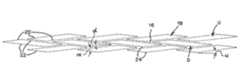
- FIG. 1is a side elevational view of an occlusion device according to an aspect of the present invention, with some parts broken away for clarity;
- FIG. 2is a detail view of a portion of the occlusion device of FIG. 1 ;
- FIG. 3is an enlarged plan view of a parallelogram cell pattern suitable for application to a screen member
- FIG. 4is a detail view of a screen member edge with a generally sinusoidal configuration
- FIG. 5is a detail view of an occlusion device according to another aspect of the present invention.
- FIG. 6is a detail view of an occlusion device according to yet another aspect of the present invention, with some parts broken away for clarity;
- FIG. 7is a detail view of an occlusion device according to still another aspect of the present invention.
- the occlusion device 10 of FIG. 1is a generally tubular structure with a generally tubular screen member 12 and a generally tubular support member 14 .
- the screen member 12is illustrated in FIG. 1 with selected portions broken away to show an underlying portion of the support member 14 .
- the occlusion device 10 and its constituent partsare radially expandable from a compressed condition, for delivery in an introducer, to an expanded condition within a body vessel to support the same.
- An occlusion device according to the present inventionmay be deployed with known devices and according to known methods.
- the screen member 12overlays at least a portion of the support member 14 .
- the screen member 12is provided as a mesh which is comprised of a plurality of cells 16 defining substantially parallelogram-shaped openings 18 .
- These cells 16are referred to herein as “parallelogram cells” and can be seen in greater detail in FIG. 3 as unexpanded and in FIG. 2 as expanded.
- the risk of film ruptureis substantially decreased because the openings 18 are initially formed with an offset parallelogram shape, so as to address problems associated with other structures, including those that transition from substantially linear closed slits to open diamond-like pores during deployment.
- the present offset parallelogram openingsin the as-manufactured condition, avoid or minimize stresses and fissures that tend to develop during expansion of other designs.
- a substantially cylindrical mandrel(not illustrated) is provided.
- the mandrelhas a diameter of 2.12 mm and is formed of copper.
- a thin filmis formed on the mandrel according to known methods, such as sputtering, and parallelogram-shaped openings are formed in the film, preferably by laser cutting. Forming the openings as parallelograms on a mandrel reduces the material ratio, increases the capability of loading the occlusion device into an introducer, and reduces the risk of film rupture during radial expansion of the occlusion device 10 .
- FIG. 3illustrates a pattern that may be repeated along the thin film to create the illustrated offset parallelogram cells 16 .
- the parallelogram-shaped openings 18are defined by a pair of upwardly inclined (as viewed in FIG. 3 ) parallel edges 20 intersecting a pair of downwardly inclined (as viewed in FIG. 3 ) parallel edges 22 , one of which pairs of edges is longer than the other.
- the pattern of FIG. 3is a two-dimensional representation of a portion of a cylindrical surface along a longitudinal axis; therefore, “upwardly inclined” and “downwardly inclined” designate a general relationship with respect to the longitudinal axis that has a three-dimensional element that is not explicitly illustrated in FIG. 3 .
- the edges 20 , 22are at an inclination angle “u” or “d”, as viewed in FIG. 3 , each being less than an opening angle “ ⁇ ” between one of the edges 20 and one of the other edges 22 .
- the inclination angle “u” and/or “d”can be approximately one-half of the opening angle “ ⁇ ”.
- the longer edgesare at least 1.5 times as long as the shorter edges and can be at least twice as long as the shorter edges. If the upwardly inclined edges 20 are longer than the downwardly inclined edges 22 , as indicated generally at “U”, the opening has an upward attitude generally represented by inclination angle “u” as viewed in FIG. 3 . Otherwise, if the downwardly inclined edges 22 are longer than the upwardly inclined edges 20 , as indicated generally at “D”, the opening has a downward attitude generally represented by inclination angle “d” as viewed in FIG. 3 . Inclination angles “u” and “d” typically are on the order of about 1 degree to about 20 degrees, or to about 15 degrees, typically not greater than about 12 degrees, and often not greater than about 10 degrees.
- each opening 18is defined by a vertex or corner 24 , rather than by an edge 20 , 22 , such that each opening 18 moves to the generally parallelogrammatic or skewed diamond configuration of FIG. 2 when the screen member 12 is radially expanded.
- each opening 18may instead be provided with flattened or blunted corners. At smaller opening sizes, it can become difficult to accurately manufacture tight, angular corners and, even if possible, it may be preferred to flatten or round the corners in order to provide more material between adjacent openings, and thereby further discourage film rupture.
- parallelogramwhen used herein to describe the shape of the openings as-manufactured or in a compressed condition, the term “parallelogram” includes parallelograms with one or more flattened or blunted or rounded corners and/or parallelograms with edges having some minor degree of curvature.
- the openings 18are provided in longitudinal rows according to the pattern of FIG. 3 .
- the openings of adjacent rowsare axially offset from each other such that the openings from adjacent rows are not in circumferential alignment with each other.
- each longer edge of the openingis shown adjacent to part of at least two other openings.
- the screen member 12is radially expandable and, during deployment, the opening angle “ ⁇ ” will increase as the openings 18 become taller and thinner, as shown in FIG. 2 .
- the axial deformation of the openings with upward attitudes “U”is generally in the opposite direction of that of the openings with downward attitudes “D”, so the alternating pattern of FIG. 3 provides circumferential arrays of offset openings that promote axial foreshortening of the screen member 12 that corresponds generally to that of the support member 14 .
- the screen membermay be provided with identical parallelogram cells (the upward attitude cells being mirror images of the downward attitude cells in the illustrated embodiment) arranged in a uniform pattern, which results in substantially uniform radial expansion properties at all points of the screen member. In the embodiment shown in FIG.
- the offset parallelogram openingsare arranged in axially aligned rows. Alternating rows are staggered with respect to each other so that a given parallelogram opening is adjacent to two parallelograms in an adjacent row when viewed in a circumferential direction.
- the parallelogram-shaped openingsmay be provided in a non-uniform array, or differently sized parallelogram openings may be formed along the surface of the thin film.
- the parallelogram openings 18 of FIG. 3are illustrated with identical as-manufactured opening angles “ ⁇ ”, typically between approximately 5 and 30 degrees, and can be between 5 and approximately 15 degrees. In differing embodiments, the angle can be about 7 degrees, about 8 degrees, about 9 degrees, and about 13 degrees. It will be appreciated that a range of opening sizes are possible for a given opening angle “ ⁇ ”, depending on the length of the edges. In general, the size of the openings is directly related to the porosity of the screen member, such that larger openings will result in greater porosity. Porosity can be varied without changing the opening angle. The number of openings about a circumference of the screen member depends on several factors, including the size of the openings, the diameter of the screen member, and the spacing between the openings. It will be appreciated that any number of openings may be provided without departing from the scope of the present invention.
- the openingsare sufficiently spaced to result in an opening-to-material ratio falling within the range of approximately 1.5:1 (or approximately 60% open space and 40% film material) and 4:1 (or approximately 80% open space and 20% film material).
- a thin filmis applied to a mandrel diameter of 2.12 mm, and then an alternating two-row pattern is repeated 75 times around a circumference of the film, with an opening angle of 7.57 degrees and a spacing between adjacent openings of 0.007 mm, also referred to as the strut width.
- Typical strut widthscan be between about 0.005 mm and about 0.01 mm.
- the screen member 12is radially expandable from a compressed or delivery condition to an expanded or deployed condition, so it is preferably formed of a deformable or semi-rigid material, may have shape memory attributes or not, and may be polymeric or metallic. Suitable polymeric materials include polyolefins such as polypropylenes, polyesters such as polyethylene terephathalate, polyamides, nylons and so forth. Typical screen members will have a thickness of between about 0.05 and about 0.1 mm, such as between about 0.07 and 0.08 mm.
- the screen member 12may be substantially comprised of, for example, stainless steel or an alloy such as nickel and titanium alloys or nitinols. Nitinol type metals typically will exhibit superelastic properties. Shape memory materials such as nitinols in an austenite state can be used.
- the nitinolwhen the material is a nitinol, the nitinol may be either a martensite or austenite thin film at human body temperature, which will result in different performance characteristics. If the nitinol is a martensite thin film at body temperature, then it will easily be compressed and inserted into a delivery catheter, then allow radial expansion of the occlusion device without resistance. A martensitic or superelastic nitinol is more likely to easily “go along for the ride” with the support member 14 , especially when it expands.
- a shape memory materialsuch as a nitinol is an austenite thin film at body temperature, then the screen member will actively return to its as-formed shape if the occlusion device is being designed to facilitate its recapture after being deployed in a body vessel.
- the support member 14preferably is provided as a radially expandable, generally tubular stent, as illustrated in FIG. 1 .
- the support member 14may take on many different patterns or configurations, such as a self-expanding stent, including those disclosed in U.S. Pat. Nos. 6,673,106 and 6,818,013, both to Mitelberg et al. and both of which are hereby incorporated herein by reference.
- the support membermay be provided as a balloon-expandable stent.
- the illustrated support member 14 of FIG. 1is a self-expanding stent, preferably laser cut from a tubular piece of nitinol to form a skeletal structure.
- the nitinolis preferably treated so as to exhibit superelastic properties at body temperature.
- the skeletal structurehas a thin wall, a small diameter, and when cut forms a plurality of cells which are created by a plurality of interconnected struts 26 .
- the cells of the support member 14are generally approximated by the parallelogram cells 16 of the screen member 12 . This allows the screen member 12 and the support member 14 to exhibit similar deformation properties during deployment to a body vessel. Such deformation properties include the extent of foreshortening upon expansion, because differing degrees of foreshortening between the screen member and the support member may lead to undesirable rupture and/or folding of the screen member.
- the occlusion deviceis comprised of a screen member 12 overlaying at least a portion of a support member 14 .
- the screen member 12may be fully or partially affixed to the support member 14 in order to prevent the two from rotating or otherwise moving with respect to each other.
- Suitable joinder meanswill depend on the nature of the screen member 12 and on the support member 14 , the selection of which means is a routine task for one of ordinary skill in the art. This means may include, but is not limited to, welding, soldering, adhering, crimping, or combinations thereof.
- the occlusion device 10is radially compressed into a delivery condition and inserted into the distal end of an introducer (not shown).
- the occlusion device 10may be mounted about a guidewire or a balloon catheter before being compressed and inserted into the introducer.
- the openings 18 of the screen member 12move from the relatively open parallelogram shape of FIGS. 1 and 2 to a more closed parallelogram shape having a smaller opening angle “ ⁇ ” in the compressed condition.
- the peripheral edges at the axial ends of the screencan be non-linear, in that they do not lie fully within a radial plane. They do not follow a circular path, but instead follow an undulating path to provide “wavy ends.”
- the proximal edge 28 of the screen member 12may be provided with a generally sinusoidal configuration, as illustrated in greater detail in FIG. 4 .
- a flat or non-undulating edgemay become folded upon itself when compressed and inserted into an introducer, thereby increasing friction and the associated push forces. This is analogous to folding that occurs when a mitten is forced into a tight pocket.
- extensions 30 of the edge 28may move toward each other without overlapping when the device is compressed, analogous to gloved fingers moving together when inserted into a tight pocket.
- the introducerWhen the occlusion device 10 has been properly loaded, the introducer is moved into the interior of a body vessel and positioned adjacent to a region of the vessel which is to be occluded. Finally, the occlusion device 10 is ejected from the introducer and into the target region. If the support member is not self-expanding, then a balloon is expanded to force the occlusion device 10 against the wall of the vessel.
- the screen member 12 and the support member 14each have a separate porosity in the deployed or expanded condition of FIG. 1 . As illustrated, the porosity of the screen member 12 is less than that of the support member 14 , which effectively gives the occlusion device 10 an overall porosity less than that of the support member 14 alone.
- the occlusion devicemay be provided according to a number of various configurations in order to achieve results similar to those described above with regard to the embodiment of FIG. 1 .
- a generally tubular screen member 32instead may be mounted within a generally tubular support member 34 , as illustrated in FIG. 5 .
- the support memberis external of the screen member.
- an occlusion devicemay be provided with a generally tubular support member 36 , a generally tubular inner screen member 38 at least partially received within the support member 36 , and a generally tubular outer screen member 40 overlaying at least a portion of the support member 36 .
- Each screen membercan be secured to the support member. Also, rather than individually attaching each screen member 38 and 40 to the support member 36 , the screen members 38 and 40 may be directly attached to each other, thereby trapping the support member 36 .
- an occlusion devicemay be provided with a generally tubular inner support member 42 , a generally tubular outer support member 44 , and a generally tubular screen member 46 received between at least a portion of the inner support member 42 and at least a portion of the outer support member 44 .
- Each support membercan be secured to the sandwiched screen member.
- the support members 42 and 44may be directly attached to each other, thereby trapping the screen member 46 .
- each screen memberis radially expandable with the associated support member, has a plurality of substantially parallelogram-shaped openings in both the compressed and expanded conditions, and has a porosity that is less than that of the associated support member in the expanded condition within a body vessel.
- the screen member and/or the support membermay be coated with an agent, such as heparin or rapamycin, to prevent stenosis or restenosis of the vessel.
- agentssuch as heparin or rapamycin
- Examples of such coatingsare disclosed in U.S. Pat. Nos. 5,288,711 to Mitchell et al.; 5,516,781 to Morris et al.; 5,563,146 to Morris et al.; and 5,646,160 to Morris et al., all of which are hereby incorporated herein by reference.
- Other coatingsmay also be applied without departing from the scope of the present invention.
Landscapes
- Health & Medical Sciences (AREA)
- Surgery (AREA)
- Life Sciences & Earth Sciences (AREA)
- Heart & Thoracic Surgery (AREA)
- Molecular Biology (AREA)
- Vascular Medicine (AREA)
- Engineering & Computer Science (AREA)
- Biomedical Technology (AREA)
- Reproductive Health (AREA)
- Medical Informatics (AREA)
- Nuclear Medicine, Radiotherapy & Molecular Imaging (AREA)
- Animal Behavior & Ethology (AREA)
- General Health & Medical Sciences (AREA)
- Public Health (AREA)
- Veterinary Medicine (AREA)
- Prostheses (AREA)
- Media Introduction/Drainage Providing Device (AREA)
Abstract
Description
Claims (17)
Priority Applications (1)
| Application Number | Priority Date | Filing Date | Title |
|---|---|---|---|
| US11/420,523US8118859B2 (en) | 2006-05-26 | 2006-05-26 | Occlusion device combination of stent and mesh having offset parallelogram porosity |
Applications Claiming Priority (1)
| Application Number | Priority Date | Filing Date | Title |
|---|---|---|---|
| US11/420,523US8118859B2 (en) | 2006-05-26 | 2006-05-26 | Occlusion device combination of stent and mesh having offset parallelogram porosity |
Publications (2)
| Publication Number | Publication Date |
|---|---|
| US20070276470A1 US20070276470A1 (en) | 2007-11-29 |
| US8118859B2true US8118859B2 (en) | 2012-02-21 |
Family
ID=38750519
Family Applications (1)
| Application Number | Title | Priority Date | Filing Date |
|---|---|---|---|
| US11/420,523Active2029-02-03US8118859B2 (en) | 2006-05-26 | 2006-05-26 | Occlusion device combination of stent and mesh having offset parallelogram porosity |
Country Status (1)
| Country | Link |
|---|---|
| US (1) | US8118859B2 (en) |
Cited By (3)
| Publication number | Priority date | Publication date | Assignee | Title |
|---|---|---|---|---|
| US20120055011A1 (en)* | 2007-03-23 | 2012-03-08 | Dirk Tenne | Methods for manufacturing implantable stents having a plurality of varying parallelogrammic cells |
| WO2014186413A3 (en)* | 2013-05-13 | 2015-04-09 | Edwards Lifesciences Corporation | Aortic occlusion device |
| US10106884B2 (en)* | 1999-11-19 | 2018-10-23 | Vactronix Scientific, Llc | Compliant implantable medical devices and methods of making same |
Families Citing this family (15)
| Publication number | Priority date | Publication date | Assignee | Title |
|---|---|---|---|---|
| US8142490B2 (en)* | 2007-10-24 | 2012-03-27 | Cordis Corporation | Stent segments axially connected by thin film |
| US20090143815A1 (en)* | 2007-11-30 | 2009-06-04 | Boston Scientific Scimed, Inc. | Apparatus and Method for Sealing a Vessel Puncture Opening |
| US8974487B2 (en) | 2008-05-01 | 2015-03-10 | Aneuclose Llc | Aneurysm occlusion device |
| US8845682B2 (en) | 2009-10-13 | 2014-09-30 | E-Pacing, Inc. | Vasculature closure devices and methods |
| US8906057B2 (en) | 2010-01-04 | 2014-12-09 | Aneuclose Llc | Aneurysm embolization by rotational accumulation of mass |
| US8425548B2 (en) | 2010-07-01 | 2013-04-23 | Aneaclose LLC | Occluding member expansion and then stent expansion for aneurysm treatment |
| EP2651347B1 (en)* | 2010-12-13 | 2021-06-30 | Microvention, Inc. | Stent |
| US9867725B2 (en) | 2010-12-13 | 2018-01-16 | Microvention, Inc. | Stent |
| US20120172973A1 (en)* | 2010-12-30 | 2012-07-05 | Cook Medical Technologies Llc | Self-expanding occlusion device |
| EP2707077B1 (en) | 2011-05-11 | 2017-10-04 | Microvention, Inc. | Device for occluding a lumen |
| US9138232B2 (en) | 2011-05-24 | 2015-09-22 | Aneuclose Llc | Aneurysm occlusion by rotational dispensation of mass |
| CA2867181C (en)* | 2012-03-16 | 2020-08-11 | Microvention, Inc. | Stent and stent delivery device |
| US10219924B2 (en)* | 2012-12-26 | 2019-03-05 | Stryker Corporation | Multilayer stent |
| US9907684B2 (en) | 2013-05-08 | 2018-03-06 | Aneuclose Llc | Method of radially-asymmetric stent expansion |
| EP3021762B1 (en) | 2013-07-15 | 2020-03-04 | E-Pacing, Inc. | Vasculature closure devices |
Citations (77)
| Publication number | Priority date | Publication date | Assignee | Title |
|---|---|---|---|---|
| US4390599A (en) | 1980-07-31 | 1983-06-28 | Raychem Corporation | Enhanced recovery memory metal device |
| US4475972A (en)* | 1981-10-01 | 1984-10-09 | Ontario Research Foundation | Implantable material |
| US4864824A (en) | 1988-10-31 | 1989-09-12 | American Telephone And Telegraph Company, At&T Bell Laboratories | Thin film shape memory alloy and method for producing |
| US4981756A (en) | 1989-03-21 | 1991-01-01 | Vac-Tec Systems, Inc. | Method for coated surgical instruments and tools |
| US5061914A (en) | 1989-06-27 | 1991-10-29 | Tini Alloy Company | Shape-memory alloy micro-actuator |
| US5082359A (en) | 1989-11-28 | 1992-01-21 | Epion Corporation | Diamond films and method of growing diamond films on nondiamond substrates |
| US5178957A (en) | 1989-05-02 | 1993-01-12 | Minnesota Mining And Manufacturing Company | Noble metal-polymer composites and flexible thin-film conductors prepared therefrom |
| US5197978A (en) | 1991-04-26 | 1993-03-30 | Advanced Coronary Technology, Inc. | Removable heat-recoverable tissue supporting device |
| WO1993007924A1 (en) | 1991-10-18 | 1993-04-29 | Spire Corporation | Bactericidal coatings for implants |
| WO1993023092A1 (en) | 1992-05-19 | 1993-11-25 | Westaim Technologies Inc. | Anti-microbial coating for medical devices |
| US5288711A (en) | 1992-04-28 | 1994-02-22 | American Home Products Corporation | Method of treating hyperproliferative vascular disease |
| US5288230A (en) | 1991-07-18 | 1994-02-22 | Minnesota Mining And Manufacturing Company | Coated orthodontic archwire |
| US5334216A (en) | 1992-12-10 | 1994-08-02 | Howmedica Inc. | Hemostatic plug |
| US5360397A (en) | 1993-07-02 | 1994-11-01 | Corvita Corporation | Hemodiaylsis catheter and catheter assembly |
| WO1994025637A1 (en) | 1993-04-23 | 1994-11-10 | Etex Corporation | Method of coating medical devices and devices coated thereby |
| US5397355A (en)* | 1994-07-19 | 1995-03-14 | Stentco, Inc. | Intraluminal stent |
| US5403700A (en) | 1990-02-14 | 1995-04-04 | Eli Lilly And Company | Method of making a thin film electrical component |
| WO1995013704A1 (en) | 1993-11-18 | 1995-05-26 | Westaim Technologies Inc. | Anti-microbial materials |
| US5516781A (en) | 1992-01-09 | 1996-05-14 | American Home Products Corporation | Method of treating restenosis with rapamycin |
| US5607463A (en) | 1993-03-30 | 1997-03-04 | Medtronic, Inc. | Intravascular medical device |
| EP0759730A1 (en) | 1994-05-19 | 1997-03-05 | Scimed Life Systems, Inc. | Improved tissue supporting devices |
| US5629077A (en) | 1994-06-27 | 1997-05-13 | Advanced Cardiovascular Systems, Inc. | Biodegradable mesh and film stent |
| WO1997026026A2 (en) | 1996-01-22 | 1997-07-24 | Etex Corporation | Surface modification of medical implants |
| US5656036A (en) | 1992-09-01 | 1997-08-12 | Expandable Grafts Partnership | Apparatus for occluding vessels |
| US5669977A (en) | 1995-12-22 | 1997-09-23 | Lam Research Corporation | Shape memory alloy lift pins for semiconductor processing equipment |
| US5685961A (en) | 1992-03-27 | 1997-11-11 | P & D Medical Coatings, Inc. | Method for fabrication of metallized medical devices |
| US5735892A (en) | 1993-08-18 | 1998-04-07 | W. L. Gore & Associates, Inc. | Intraluminal stent graft |
| US5744958A (en) | 1995-11-07 | 1998-04-28 | Iti Medical Technologies, Inc. | Instrument having ultra-thin conductive coating and method for magnetic resonance imaging of such instrument |
| US5766176A (en)* | 1996-09-11 | 1998-06-16 | Walter Lorenz Surgical, Inc. | Formable mesh |
| EP0847733A1 (en) | 1996-12-10 | 1998-06-17 | BIOTRONIK Mess- und Therapiegeräte GmbH & Co Ingenieurbüro Berlin | Stent |
| US5824043A (en)* | 1994-03-09 | 1998-10-20 | Cordis Corporation | Endoprosthesis having graft member and exposed welded end junctions, method and procedure |
| US5824054A (en) | 1997-03-18 | 1998-10-20 | Endotex Interventional Systems, Inc. | Coiled sheet graft stent and methods of making and use |
| US5902317A (en) | 1994-06-01 | 1999-05-11 | Nitinol Medical Technologies, Inc. | Stent and method and apparatus for forming and delivering the same |
| US5908409A (en) | 1997-08-26 | 1999-06-01 | Mcghan Medical Corporation | Tubing plug |
| GB2331998A (en) | 1997-12-02 | 1999-06-09 | Teer Coatings Ltd | Articles bearing carbon coatings |
| US5925038A (en) | 1996-01-19 | 1999-07-20 | Ep Technologies, Inc. | Expandable-collapsible electrode structures for capacitive coupling to tissue |
| US5938697A (en) | 1998-03-04 | 1999-08-17 | Scimed Life Systems, Inc. | Stent having variable properties |
| US5945153A (en) | 1994-07-11 | 1999-08-31 | Southwest Research Institute | Non-irritating antimicrobial coating for medical implants and a process for preparing same |
| US5951586A (en) | 1996-05-15 | 1999-09-14 | Medtronic, Inc. | Intraluminal stent |
| WO1999066966A1 (en) | 1998-06-22 | 1999-12-29 | Anatoly Dosta | Thin-film coating for a bone implant |
| US6015402A (en) | 1997-03-07 | 2000-01-18 | Sahota; Harvinder | Wire perfusion catheter |
| US6017553A (en) | 1992-05-19 | 2000-01-25 | Westaim Technologies, Inc. | Anti-microbial materials |
| WO2000004204A1 (en) | 1998-07-17 | 2000-01-27 | Micro Therapeutics, Inc. | Thin film stent |
| US6027526A (en) | 1996-04-10 | 2000-02-22 | Advanced Cardiovascular Systems, Inc. | Stent having varied amounts of structural strength along its length |
| US6043451A (en) | 1997-11-06 | 2000-03-28 | Promet Technologies, Inc. | Plasma spraying of nickel-titanium compound |
| US6174329B1 (en) | 1996-08-22 | 2001-01-16 | Advanced Cardiovascular Systems, Inc. | Protective coating for a stent with intermediate radiopaque coating |
| US6203732B1 (en) | 1998-07-02 | 2001-03-20 | Intra Therapeutics, Inc. | Method for manufacturing intraluminal device |
| US6270872B1 (en) | 1998-05-19 | 2001-08-07 | Schering-Plough Healthcare Products, Inc. | Parylene coated devices with adhesive |
| US6296661B1 (en)* | 2000-02-01 | 2001-10-02 | Luis A. Davila | Self-expanding stent-graft |
| US6312463B1 (en) | 2000-02-01 | 2001-11-06 | Endotex Interventional Systems, Inc. | Micro-porous mesh stent with hybrid structure |
| US20010039449A1 (en) | 2000-01-24 | 2001-11-08 | A. David Johnson | Thin-film shape memory alloy device and method |
| US6319277B1 (en) | 1994-08-12 | 2001-11-20 | Meadox Medicals, Inc. | Nested stent |
| US6322588B1 (en) | 1999-08-17 | 2001-11-27 | St. Jude Medical, Inc. | Medical devices with metal/polymer composites |
| US6325824B2 (en) | 1998-07-22 | 2001-12-04 | Advanced Cardiovascular Systems, Inc. | Crush resistant stent |
| US6342067B1 (en) | 1998-01-09 | 2002-01-29 | Nitinol Development Corporation | Intravascular stent having curved bridges for connecting adjacent hoops |
| US6402771B1 (en)* | 1999-12-23 | 2002-06-11 | Guidant Endovascular Solutions | Snare |
| US6432116B1 (en) | 1996-12-18 | 2002-08-13 | Ovion, Inc. | Occluding device and method of use |
| US6436132B1 (en) | 2000-03-30 | 2002-08-20 | Advanced Cardiovascular Systems, Inc. | Composite intraluminal prostheses |
| US6447478B1 (en) | 1998-05-15 | 2002-09-10 | Ronald S. Maynard | Thin-film shape memory alloy actuators and processing methods |
| US6471721B1 (en) | 1999-12-30 | 2002-10-29 | Advanced Cardiovascular Systems, Inc. | Vascular stent having increased radiopacity and method for making same |
| US6537310B1 (en) | 1999-11-19 | 2003-03-25 | Advanced Bio Prosthetic Surfaces, Ltd. | Endoluminal implantable devices and method of making same |
| US6605111B2 (en) | 1998-06-04 | 2003-08-12 | New York University | Endovascular thin film devices and methods for treating and preventing stroke |
| US6627246B2 (en) | 2000-05-16 | 2003-09-30 | Ortho-Mcneil Pharmaceutical, Inc. | Process for coating stents and other medical devices using super-critical carbon dioxide |
| US6645243B2 (en) | 1997-01-09 | 2003-11-11 | Sorin Biomedica Cardio S.P.A. | Stent for angioplasty and a production process therefor |
| US6660032B2 (en) | 1999-02-26 | 2003-12-09 | Vascular Architects, Inc. | Expandable coil endoluminal prosthesis |
| US6673106B2 (en) | 2001-06-14 | 2004-01-06 | Cordis Neurovascular, Inc. | Intravascular stent device |
| US20040098094A1 (en) | 2002-09-26 | 2004-05-20 | Boyle Christopher T. | Implantable graft and methods of making same |
| US6786920B2 (en) | 1996-07-03 | 2004-09-07 | Edwards Lifesciences Corporation | Radially expandable stented tubular PTFE grafts |
| US6805898B1 (en) | 2000-09-28 | 2004-10-19 | Advanced Cardiovascular Systems, Inc. | Surface features of an implantable medical device |
| US6818013B2 (en) | 2001-06-14 | 2004-11-16 | Cordis Corporation | Intravascular stent device |
| US20050010175A1 (en) | 2003-02-27 | 2005-01-13 | Beedon Daniel E. | Piston assembly for syringe |
| US6865810B2 (en) | 2002-06-27 | 2005-03-15 | Scimed Life Systems, Inc. | Methods of making medical devices |
| US20050154449A1 (en) | 2002-07-31 | 2005-07-14 | David Elmaleh | Non-biodegradable drug-eluting sleeves for intravascular devices |
| US6921414B2 (en)* | 2000-06-30 | 2005-07-26 | Vascular Architects, Inc. | Endoluminal prosthesis and tissue separation condition treatment method |
| US6938668B2 (en) | 2000-01-25 | 2005-09-06 | Scimed Life Systems, Inc. | Manufacturing medical devices by vapor deposition |
| US6955685B2 (en) | 2002-09-23 | 2005-10-18 | Cordis Neurovascular, Inc. | Expandable stent with radiopaque markers and stent delivery system |
| US20080004653A1 (en)* | 2004-09-17 | 2008-01-03 | Sherman Darren R | Thin Film Devices for Occlusion of a Vessel |
- 2006
- 2006-05-26USUS11/420,523patent/US8118859B2/enactiveActive
Patent Citations (98)
| Publication number | Priority date | Publication date | Assignee | Title |
|---|---|---|---|---|
| US4390599A (en) | 1980-07-31 | 1983-06-28 | Raychem Corporation | Enhanced recovery memory metal device |
| US4475972A (en)* | 1981-10-01 | 1984-10-09 | Ontario Research Foundation | Implantable material |
| US4864824A (en) | 1988-10-31 | 1989-09-12 | American Telephone And Telegraph Company, At&T Bell Laboratories | Thin film shape memory alloy and method for producing |
| US4981756A (en) | 1989-03-21 | 1991-01-01 | Vac-Tec Systems, Inc. | Method for coated surgical instruments and tools |
| US5178957A (en) | 1989-05-02 | 1993-01-12 | Minnesota Mining And Manufacturing Company | Noble metal-polymer composites and flexible thin-film conductors prepared therefrom |
| US5061914A (en) | 1989-06-27 | 1991-10-29 | Tini Alloy Company | Shape-memory alloy micro-actuator |
| US5082359A (en) | 1989-11-28 | 1992-01-21 | Epion Corporation | Diamond films and method of growing diamond films on nondiamond substrates |
| US5403700A (en) | 1990-02-14 | 1995-04-04 | Eli Lilly And Company | Method of making a thin film electrical component |
| US5197978A (en) | 1991-04-26 | 1993-03-30 | Advanced Coronary Technology, Inc. | Removable heat-recoverable tissue supporting device |
| US5197978B1 (en) | 1991-04-26 | 1996-05-28 | Advanced Coronary Tech | Removable heat-recoverable tissue supporting device |
| US5288230A (en) | 1991-07-18 | 1994-02-22 | Minnesota Mining And Manufacturing Company | Coated orthodontic archwire |
| WO1993007924A1 (en) | 1991-10-18 | 1993-04-29 | Spire Corporation | Bactericidal coatings for implants |
| US5516781A (en) | 1992-01-09 | 1996-05-14 | American Home Products Corporation | Method of treating restenosis with rapamycin |
| US5646160A (en) | 1992-01-09 | 1997-07-08 | American Home Products Corporation | Method of treating hyperproliferative vascular disease with rapamycin and mycophenolic acid |
| US5563146A (en) | 1992-01-09 | 1996-10-08 | American Home Products Corporation | Method of treating hyperproliferative vascular disease |
| US5685961A (en) | 1992-03-27 | 1997-11-11 | P & D Medical Coatings, Inc. | Method for fabrication of metallized medical devices |
| US5288711A (en) | 1992-04-28 | 1994-02-22 | American Home Products Corporation | Method of treating hyperproliferative vascular disease |
| WO1993023092A1 (en) | 1992-05-19 | 1993-11-25 | Westaim Technologies Inc. | Anti-microbial coating for medical devices |
| US6017553A (en) | 1992-05-19 | 2000-01-25 | Westaim Technologies, Inc. | Anti-microbial materials |
| US6238686B1 (en) | 1992-05-19 | 2001-05-29 | Westaim Technologies | Anti-microbial coating for medical devices |
| EP0641224B1 (en) | 1992-05-19 | 1998-08-19 | Westaim Technologies Inc. | Anti-microbial coating for medical devices |
| US5770255A (en) | 1992-05-19 | 1998-06-23 | Westaim Technologies, Inc. | Anti-microbial coating for medical devices |
| US5753251A (en) | 1992-05-19 | 1998-05-19 | Westaim Technologies, Inc. | Anti-microbial coating for medical device |
| US5681575A (en) | 1992-05-19 | 1997-10-28 | Westaim Technologies Inc. | Anti-microbial coating for medical devices |
| US5656036A (en) | 1992-09-01 | 1997-08-12 | Expandable Grafts Partnership | Apparatus for occluding vessels |
| US5334216A (en) | 1992-12-10 | 1994-08-02 | Howmedica Inc. | Hemostatic plug |
| US5607463A (en) | 1993-03-30 | 1997-03-04 | Medtronic, Inc. | Intravascular medical device |
| US5543019A (en) | 1993-04-23 | 1996-08-06 | Etex Corporation | Method of coating medical devices and device coated thereby |
| WO1994025637A1 (en) | 1993-04-23 | 1994-11-10 | Etex Corporation | Method of coating medical devices and devices coated thereby |
| US5360397A (en) | 1993-07-02 | 1994-11-01 | Corvita Corporation | Hemodiaylsis catheter and catheter assembly |
| US5810870A (en) | 1993-08-18 | 1998-09-22 | W. L. Gore & Associates, Inc. | Intraluminal stent graft |
| US5735892A (en) | 1993-08-18 | 1998-04-07 | W. L. Gore & Associates, Inc. | Intraluminal stent graft |
| US5925075A (en) | 1993-08-18 | 1999-07-20 | W. L. Gore & Associates, Inc. | Intraluminal stent graft |
| WO1995013704A1 (en) | 1993-11-18 | 1995-05-26 | Westaim Technologies Inc. | Anti-microbial materials |
| US5824043A (en)* | 1994-03-09 | 1998-10-20 | Cordis Corporation | Endoprosthesis having graft member and exposed welded end junctions, method and procedure |
| EP0759730A1 (en) | 1994-05-19 | 1997-03-05 | Scimed Life Systems, Inc. | Improved tissue supporting devices |
| US5902317A (en) | 1994-06-01 | 1999-05-11 | Nitinol Medical Technologies, Inc. | Stent and method and apparatus for forming and delivering the same |
| US5766710A (en) | 1994-06-27 | 1998-06-16 | Advanced Cardiovascular Systems, Inc. | Biodegradable mesh and film stent |
| US5629077A (en) | 1994-06-27 | 1997-05-13 | Advanced Cardiovascular Systems, Inc. | Biodegradable mesh and film stent |
| US5945153A (en) | 1994-07-11 | 1999-08-31 | Southwest Research Institute | Non-irritating antimicrobial coating for medical implants and a process for preparing same |
| US5397355A (en)* | 1994-07-19 | 1995-03-14 | Stentco, Inc. | Intraluminal stent |
| US6319277B1 (en) | 1994-08-12 | 2001-11-20 | Meadox Medicals, Inc. | Nested stent |
| US5744958A (en) | 1995-11-07 | 1998-04-28 | Iti Medical Technologies, Inc. | Instrument having ultra-thin conductive coating and method for magnetic resonance imaging of such instrument |
| US5669977A (en) | 1995-12-22 | 1997-09-23 | Lam Research Corporation | Shape memory alloy lift pins for semiconductor processing equipment |
| US5925038A (en) | 1996-01-19 | 1999-07-20 | Ep Technologies, Inc. | Expandable-collapsible electrode structures for capacitive coupling to tissue |
| US5843289A (en) | 1996-01-22 | 1998-12-01 | Etex Corporation | Surface modification of medical implants |
| WO1997026026A2 (en) | 1996-01-22 | 1997-07-24 | Etex Corporation | Surface modification of medical implants |
| US6027526A (en) | 1996-04-10 | 2000-02-22 | Advanced Cardiovascular Systems, Inc. | Stent having varied amounts of structural strength along its length |
| US5951586A (en) | 1996-05-15 | 1999-09-14 | Medtronic, Inc. | Intraluminal stent |
| US6786920B2 (en) | 1996-07-03 | 2004-09-07 | Edwards Lifesciences Corporation | Radially expandable stented tubular PTFE grafts |
| US6174329B1 (en) | 1996-08-22 | 2001-01-16 | Advanced Cardiovascular Systems, Inc. | Protective coating for a stent with intermediate radiopaque coating |
| EP0824900B1 (en) | 1996-08-22 | 2003-04-02 | Advanced Cardiovascular Systems, Inc. | Protective coating for a stent |
| US5766176A (en)* | 1996-09-11 | 1998-06-16 | Walter Lorenz Surgical, Inc. | Formable mesh |
| EP0847733A1 (en) | 1996-12-10 | 1998-06-17 | BIOTRONIK Mess- und Therapiegeräte GmbH & Co Ingenieurbüro Berlin | Stent |
| US6432116B1 (en) | 1996-12-18 | 2002-08-13 | Ovion, Inc. | Occluding device and method of use |
| US6645243B2 (en) | 1997-01-09 | 2003-11-11 | Sorin Biomedica Cardio S.P.A. | Stent for angioplasty and a production process therefor |
| US6015402A (en) | 1997-03-07 | 2000-01-18 | Sahota; Harvinder | Wire perfusion catheter |
| US5824054A (en) | 1997-03-18 | 1998-10-20 | Endotex Interventional Systems, Inc. | Coiled sheet graft stent and methods of making and use |
| US5908409A (en) | 1997-08-26 | 1999-06-01 | Mcghan Medical Corporation | Tubing plug |
| US6043451A (en) | 1997-11-06 | 2000-03-28 | Promet Technologies, Inc. | Plasma spraying of nickel-titanium compound |
| US6726993B2 (en) | 1997-12-02 | 2004-04-27 | Teer Coatings Limited | Carbon coatings, method and apparatus for applying them, and articles bearing such coatings |
| GB2331998A (en) | 1997-12-02 | 1999-06-09 | Teer Coatings Ltd | Articles bearing carbon coatings |
| US6342067B1 (en) | 1998-01-09 | 2002-01-29 | Nitinol Development Corporation | Intravascular stent having curved bridges for connecting adjacent hoops |
| US5938697A (en) | 1998-03-04 | 1999-08-17 | Scimed Life Systems, Inc. | Stent having variable properties |
| US6447478B1 (en) | 1998-05-15 | 2002-09-10 | Ronald S. Maynard | Thin-film shape memory alloy actuators and processing methods |
| US6270872B1 (en) | 1998-05-19 | 2001-08-07 | Schering-Plough Healthcare Products, Inc. | Parylene coated devices with adhesive |
| US6666882B1 (en) | 1998-06-04 | 2003-12-23 | New York University | Endovascular thin film devices and methods for treating and preventing stroke |
| US6605111B2 (en) | 1998-06-04 | 2003-08-12 | New York University | Endovascular thin film devices and methods for treating and preventing stroke |
| WO1999066966A1 (en) | 1998-06-22 | 1999-12-29 | Anatoly Dosta | Thin-film coating for a bone implant |
| US6203732B1 (en) | 1998-07-02 | 2001-03-20 | Intra Therapeutics, Inc. | Method for manufacturing intraluminal device |
| EP1099004B1 (en) | 1998-07-17 | 2004-09-29 | Micro Therapeutics, Inc. | Thin film stent |
| EP1099004A1 (en) | 1998-07-17 | 2001-05-16 | Micro Therapeutics, Inc. | Thin film stent |
| WO2000004204A1 (en) | 1998-07-17 | 2000-01-27 | Micro Therapeutics, Inc. | Thin film stent |
| US6527919B1 (en) | 1998-07-17 | 2003-03-04 | Micro Therapeutics, Inc. | Thin film stent |
| US6096175A (en) | 1998-07-17 | 2000-08-01 | Micro Therapeutics, Inc. | Thin film stent |
| US6325824B2 (en) | 1998-07-22 | 2001-12-04 | Advanced Cardiovascular Systems, Inc. | Crush resistant stent |
| US6660032B2 (en) | 1999-02-26 | 2003-12-09 | Vascular Architects, Inc. | Expandable coil endoluminal prosthesis |
| US6322588B1 (en) | 1999-08-17 | 2001-11-27 | St. Jude Medical, Inc. | Medical devices with metal/polymer composites |
| US6537310B1 (en) | 1999-11-19 | 2003-03-25 | Advanced Bio Prosthetic Surfaces, Ltd. | Endoluminal implantable devices and method of making same |
| US6402771B1 (en)* | 1999-12-23 | 2002-06-11 | Guidant Endovascular Solutions | Snare |
| US6471721B1 (en) | 1999-12-30 | 2002-10-29 | Advanced Cardiovascular Systems, Inc. | Vascular stent having increased radiopacity and method for making same |
| US20010039449A1 (en) | 2000-01-24 | 2001-11-08 | A. David Johnson | Thin-film shape memory alloy device and method |
| US6533905B2 (en) | 2000-01-24 | 2003-03-18 | Tini Alloy Company | Method for sputtering tini shape-memory alloys |
| US6938668B2 (en) | 2000-01-25 | 2005-09-06 | Scimed Life Systems, Inc. | Manufacturing medical devices by vapor deposition |
| US6296661B1 (en)* | 2000-02-01 | 2001-10-02 | Luis A. Davila | Self-expanding stent-graft |
| US6312463B1 (en) | 2000-02-01 | 2001-11-06 | Endotex Interventional Systems, Inc. | Micro-porous mesh stent with hybrid structure |
| US6436132B1 (en) | 2000-03-30 | 2002-08-20 | Advanced Cardiovascular Systems, Inc. | Composite intraluminal prostheses |
| US6627246B2 (en) | 2000-05-16 | 2003-09-30 | Ortho-Mcneil Pharmaceutical, Inc. | Process for coating stents and other medical devices using super-critical carbon dioxide |
| US6921414B2 (en)* | 2000-06-30 | 2005-07-26 | Vascular Architects, Inc. | Endoluminal prosthesis and tissue separation condition treatment method |
| US6805898B1 (en) | 2000-09-28 | 2004-10-19 | Advanced Cardiovascular Systems, Inc. | Surface features of an implantable medical device |
| US6818013B2 (en) | 2001-06-14 | 2004-11-16 | Cordis Corporation | Intravascular stent device |
| US6673106B2 (en) | 2001-06-14 | 2004-01-06 | Cordis Neurovascular, Inc. | Intravascular stent device |
| US6865810B2 (en) | 2002-06-27 | 2005-03-15 | Scimed Life Systems, Inc. | Methods of making medical devices |
| US20050154449A1 (en) | 2002-07-31 | 2005-07-14 | David Elmaleh | Non-biodegradable drug-eluting sleeves for intravascular devices |
| US6955685B2 (en) | 2002-09-23 | 2005-10-18 | Cordis Neurovascular, Inc. | Expandable stent with radiopaque markers and stent delivery system |
| US20040098094A1 (en) | 2002-09-26 | 2004-05-20 | Boyle Christopher T. | Implantable graft and methods of making same |
| US20050010175A1 (en) | 2003-02-27 | 2005-01-13 | Beedon Daniel E. | Piston assembly for syringe |
| US20080004653A1 (en)* | 2004-09-17 | 2008-01-03 | Sherman Darren R | Thin Film Devices for Occlusion of a Vessel |
Non-Patent Citations (10)
| Title |
|---|
| Advances in Bioengineering; Chung, Chang, Han; Development of thin metal film deposition process for the intravascular catheter; Conference; Nov. 14, 1999; US. |
| American Journal of Neuroradiology, Higashida et al., Initial clinical experience with a new self-expanding nitinol stent for the treatment of intracranial cerebral aneurysms: the Cordis Enterprise stent, Aug. 2005. |
| Asaio; Zabetakis, Cotell, Chrisey, Auyeung; Pulsed laser deposition of thin film hydroxyapatite. Applications for flexible catheters; 896-899; Jul. 1994; US. |
| Biomaterials; LI; Behaviour of titanium and titania-based ceramics in vitro and in vivo; Feb. 2003; US. |
| Elsevier; Banks et al,; Ion bombardment modification of surfaces in biomedical applications; 399-434; 1984; Netherlands. |
| Journal of Biomedical Materials Research; Yuhta et al ; Blood compatibility of sputter deposited alumina films; 271-224; Feb. 1994. |
| Journal of Materials Processing Technology; Kola, Daniels, Cameron, Hashmi; Magnetron suputtering of TiN protective coatings for medical applications; 422-430; Jan. 1996; Ireland. |
| Neurological Research, Lieber et al., The physics of endoluminal stenting in the treatment of cerebrovasilar aneurusms, 2002. |
| Society for Biomaterials; Ong, Lucas, Lacefield, Rigney; Properties of calcium-phosphate coatings produced by ion-beam sputter deposition; Conference; May 1, 1991; US. |
| Spine; Hellier, Hedman, Kostuik; Wear Studies for development of an intervertebral disc prosteses; Jun. 1992; US. |
Cited By (8)
| Publication number | Priority date | Publication date | Assignee | Title |
|---|---|---|---|---|
| US10106884B2 (en)* | 1999-11-19 | 2018-10-23 | Vactronix Scientific, Llc | Compliant implantable medical devices and methods of making same |
| US20120055011A1 (en)* | 2007-03-23 | 2012-03-08 | Dirk Tenne | Methods for manufacturing implantable stents having a plurality of varying parallelogrammic cells |
| US8549722B2 (en)* | 2007-03-23 | 2013-10-08 | DePuy Synthes Products, LLC | Methods for manufacturing implantable stents having a plurality of varying parallelogrammic cells |
| WO2014186413A3 (en)* | 2013-05-13 | 2015-04-09 | Edwards Lifesciences Corporation | Aortic occlusion device |
| CN105208943A (en)* | 2013-05-13 | 2015-12-30 | 爱德华兹生命科学公司 | Aortic occlusion device |
| US10130371B2 (en) | 2013-05-13 | 2018-11-20 | Edwards Lifesciences Corporation | Aortic occlusion device |
| US10667821B2 (en) | 2013-05-13 | 2020-06-02 | Edwards Lifesciences Corporation | Aortic occlusion device |
| US11571216B2 (en) | 2013-05-13 | 2023-02-07 | Edwards Lifesciences Corporation | Aortic occlusion device |
Also Published As
| Publication number | Publication date |
|---|---|
| US20070276470A1 (en) | 2007-11-29 |
Similar Documents
| Publication | Publication Date | Title |
|---|---|---|
| US8118859B2 (en) | Occlusion device combination of stent and mesh having offset parallelogram porosity | |
| US8690938B2 (en) | Occlusion device combination of stent and mesh with diamond-shaped porosity | |
| US12232987B2 (en) | Stent | |
| US8075610B2 (en) | Endoprosthesis for controlled contraction and expansion | |
| US7625398B2 (en) | Endoprosthesis having foot extensions | |
| US8109991B2 (en) | Endoprosthesis having foot extensions | |
| EP2249744B1 (en) | Stent having adjacent elements connected by flexible webs | |
| US6036725A (en) | Expandable endovascular support device | |
| US20080051876A1 (en) | Intravascular stent | |
| US20080243227A1 (en) | Radiopaque markers for implantable stents and methods for manufacturing the same | |
| JP2009515589A (en) | Stent with helical side branch support design | |
| US8549722B2 (en) | Methods for manufacturing implantable stents having a plurality of varying parallelogrammic cells | |
| US20090018641A1 (en) | Large vessel stents | |
| EP1991175A1 (en) | Tapered strength rings on a bifurcated stent petal | |
| US20210251783A1 (en) | Helical stent with enhanced crimping | |
| HK1145431A (en) | Stent having adjacent elements connected by flexible webs | |
| HK1145431B (en) | Stent having adjacent elements connected by flexible webs |
Legal Events
| Date | Code | Title | Description |
|---|---|---|---|
| AS | Assignment | Owner name:CORDIS DEVELOPMENT CORPORATION, FLORIDA Free format text:ASSIGNMENT OF ASSIGNORS INTEREST;ASSIGNOR:TENNE, DIRK;REEL/FRAME:017684/0678 Effective date:20060526 | |
| AS | Assignment | Owner name:CORDIS NEUROVASCULAR, INC., FLORIDA Free format text:MERGER;ASSIGNORS:CORDIS DEVELOPMENT CORPORATION;CORDIS NEUROVASCULAR, INC.;REEL/FRAME:023085/0329 Effective date:20081229 Owner name:CODMAN & SHURTLEFF, INC., MASSACHUSETTS Free format text:MERGER;ASSIGNORS:CORDIS DEVELOPMENT CORPORATION;CORDIS NEUROVASCULAR, INC.;REEL/FRAME:023085/0329 Effective date:20081229 Owner name:CORDIS NEUROVASCULAR, INC.,FLORIDA Free format text:MERGER;ASSIGNORS:CORDIS DEVELOPMENT CORPORATION;CORDIS NEUROVASCULAR, INC.;REEL/FRAME:023085/0329 Effective date:20081229 Owner name:CODMAN & SHURTLEFF, INC.,MASSACHUSETTS Free format text:MERGER;ASSIGNORS:CORDIS DEVELOPMENT CORPORATION;CORDIS NEUROVASCULAR, INC.;REEL/FRAME:023085/0329 Effective date:20081229 | |
| AS | Assignment | Owner name:CODMAN & SHURTLEFF, INC., MASSACHUSETTS Free format text:CORRECTIVE ASSIGNMENT TO CORRECT THE RE-RECORDING ASSIGNMENTS TO REMOVE INCORRECT DATA RECORDED ON 08/12/2009. PREVIOUSLY RECORDED ON REEL 023085 FRAME 0329. ASSIGNOR(S) HEREBY CONFIRMS THE MERGER OF CORDIS DEVELOPMENT CORP. AND CORDIS NEUROVASCULAR, INC. INTO CODMAN & SHURTLEFF;ASSIGNORS:CORDIS DEVELOPMENT CORPORATION;CORDIS NEUROVASCULAR, INC.;REEL/FRAME:024776/0472 Effective date:20081229 | |
| STCF | Information on status: patent grant | Free format text:PATENTED CASE | |
| FPAY | Fee payment | Year of fee payment:4 | |
| MAFP | Maintenance fee payment | Free format text:PAYMENT OF MAINTENANCE FEE, 8TH YEAR, LARGE ENTITY (ORIGINAL EVENT CODE: M1552); ENTITY STATUS OF PATENT OWNER: LARGE ENTITY Year of fee payment:8 | |
| MAFP | Maintenance fee payment | Free format text:PAYMENT OF MAINTENANCE FEE, 12TH YEAR, LARGE ENTITY (ORIGINAL EVENT CODE: M1553); ENTITY STATUS OF PATENT OWNER: LARGE ENTITY Year of fee payment:12 |