US8118853B2 - Prosthesis delivery and deployment device - Google Patents
Prosthesis delivery and deployment deviceDownload PDFInfo
- Publication number
- US8118853B2 US8118853B2US11/764,969US76496907AUS8118853B2US 8118853 B2US8118853 B2US 8118853B2US 76496907 AUS76496907 AUS 76496907AUS 8118853 B2US8118853 B2US 8118853B2
- Authority
- US
- United States
- Prior art keywords
- sheath
- delivery catheter
- vessel
- distal end
- proximal end
- Prior art date
- Legal status (The legal status is an assumption and is not a legal conclusion. Google has not performed a legal analysis and makes no representation as to the accuracy of the status listed.)
- Active, expires
Links
- 230000007246mechanismEffects0.000claimsabstractdescription79
- 230000008602contractionEffects0.000claimsabstractdescription38
- 238000000034methodMethods0.000claimsabstractdescription19
- 238000006243chemical reactionMethods0.000claimsdescription22
- 238000004891communicationMethods0.000claimsdescription15
- 230000007423decreaseEffects0.000claimsdescription6
- 230000008878couplingEffects0.000claims3
- 238000010168coupling processMethods0.000claims3
- 238000005859coupling reactionMethods0.000claims3
- -1polytetrafluoroethylenePolymers0.000description15
- 239000000463materialSubstances0.000description13
- 229940030225antihemorrhagicsDrugs0.000description10
- 230000000025haemostatic effectEffects0.000description10
- 229920001343polytetrafluoroethylenePolymers0.000description7
- 239000004810polytetrafluoroethyleneSubstances0.000description7
- 238000007789sealingMethods0.000description7
- 229920002313fluoropolymerPolymers0.000description4
- 230000008901benefitEffects0.000description3
- 229920001971elastomerPolymers0.000description3
- 239000004811fluoropolymerSubstances0.000description3
- 229920002635polyurethanePolymers0.000description3
- 239000004814polyurethaneSubstances0.000description3
- 230000000717retained effectEffects0.000description3
- 239000005060rubberSubstances0.000description3
- 229920002725thermoplastic elastomerPolymers0.000description3
- 229920002397thermoplastic olefinPolymers0.000description3
- 239000002184metalSubstances0.000description2
- 229920001296polysiloxanePolymers0.000description2
- 239000010935stainless steelSubstances0.000description2
- 229910001220stainless steelInorganic materials0.000description2
- 230000007704transitionEffects0.000description2
- BVKZGUZCCUSVTD-UHFFFAOYSA-LCarbonateChemical compound[O-]C([O-])=OBVKZGUZCCUSVTD-UHFFFAOYSA-L0.000description1
- 229910000684Cobalt-chromeInorganic materials0.000description1
- AEMRFAOFKBGASW-UHFFFAOYSA-NGlycolic acidPolymersOCC(O)=OAEMRFAOFKBGASW-UHFFFAOYSA-N0.000description1
- 239000004677NylonSubstances0.000description1
- 239000004698PolyethyleneSubstances0.000description1
- 229920000954PolyglycolidePolymers0.000description1
- 201000008982Thoracic Aortic AneurysmDiseases0.000description1
- 208000002223abdominal aortic aneurysmDiseases0.000description1
- 238000004873anchoringMethods0.000description1
- 210000000709aortaAnatomy0.000description1
- 210000000013bile ductAnatomy0.000description1
- 239000000560biocompatible materialSubstances0.000description1
- 239000008280bloodSubstances0.000description1
- 210000004369bloodAnatomy0.000description1
- 210000004204blood vesselAnatomy0.000description1
- 235000013877carbamideNutrition0.000description1
- 239000003153chemical reaction reagentSubstances0.000description1
- 238000000576coating methodMethods0.000description1
- 239000010952cobalt-chromeSubstances0.000description1
- 229920001577copolymerPolymers0.000description1
- 235000013870dimethyl polysiloxaneNutrition0.000description1
- 239000004205dimethyl polysiloxaneSubstances0.000description1
- KPUWHANPEXNPJT-UHFFFAOYSA-NdisiloxaneChemical class[SiH3]O[SiH3]KPUWHANPEXNPJT-UHFFFAOYSA-N0.000description1
- 210000003238esophagusAnatomy0.000description1
- 239000004744fabricSubstances0.000description1
- 229920002457flexible plasticPolymers0.000description1
- 208000014674injuryDiseases0.000description1
- 238000003780insertionMethods0.000description1
- 230000037431insertionEffects0.000description1
- 230000014759maintenance of locationEffects0.000description1
- HLXZNVUGXRDIFK-UHFFFAOYSA-Nnickel titaniumChemical compound[Ti].[Ti].[Ti].[Ti].[Ti].[Ti].[Ti].[Ti].[Ti].[Ti].[Ti].[Ni].[Ni].[Ni].[Ni].[Ni].[Ni].[Ni].[Ni].[Ni].[Ni].[Ni].[Ni].[Ni].[Ni]HLXZNVUGXRDIFK-UHFFFAOYSA-N0.000description1
- 229910001000nickel titaniumInorganic materials0.000description1
- 229920001778nylonPolymers0.000description1
- 229920000435poly(dimethylsiloxane)Polymers0.000description1
- 229920000747poly(lactic acid)Polymers0.000description1
- 229920000728polyesterPolymers0.000description1
- 229920000573polyethylenePolymers0.000description1
- 229920000139polyethylene terephthalatePolymers0.000description1
- 239000005020polyethylene terephthalateSubstances0.000description1
- 229920000642polymerPolymers0.000description1
- 229920003226polyurethane ureaPolymers0.000description1
- 229920002981polyvinylidene fluoridePolymers0.000description1
- 239000011148porous materialSubstances0.000description1
- 230000008733traumaEffects0.000description1
- 150000003672ureasChemical class0.000description1
Images


Classifications
- A—HUMAN NECESSITIES
- A61—MEDICAL OR VETERINARY SCIENCE; HYGIENE
- A61F—FILTERS IMPLANTABLE INTO BLOOD VESSELS; PROSTHESES; DEVICES PROVIDING PATENCY TO, OR PREVENTING COLLAPSING OF, TUBULAR STRUCTURES OF THE BODY, e.g. STENTS; ORTHOPAEDIC, NURSING OR CONTRACEPTIVE DEVICES; FOMENTATION; TREATMENT OR PROTECTION OF EYES OR EARS; BANDAGES, DRESSINGS OR ABSORBENT PADS; FIRST-AID KITS
- A61F2/00—Filters implantable into blood vessels; Prostheses, i.e. artificial substitutes or replacements for parts of the body; Appliances for connecting them with the body; Devices providing patency to, or preventing collapsing of, tubular structures of the body, e.g. stents
- A61F2/95—Instruments specially adapted for placement or removal of stents or stent-grafts
- A61F2/9517—Instruments specially adapted for placement or removal of stents or stent-grafts handle assemblies therefor
Definitions
- This inventionrelates to a medical device and, in particular, to a delivery and deployment device for an expandable prosthesis and a method of deploying a prosthesis in a body lumen.
- Endoluminal prosthesessuch as stents and stent grafts, are used for treating damaged or diseased body lumens such as the esophagus, bile duct, and blood vessels.
- endoluminal prosthesesmay be used for repairing diseased aortas including abdominal aortic aneurysms and thoracic aortic aneurysms.
- Such a prosthesisis placed inside the body lumen and provides some or all of the functionality of the original, healthy vessel.
- Devicessuch as the ones described in WO 98/53761 have several advantages.
- the operatorcan directly manipulate the sheath and the delivery catheter. This provides the operator with a relatively high degree of control during the procedure. Further, such devices may be compact and may have a relatively uniform, low-diameter radial profile, allowing for atraumatic access and delivery. In order to provide a low-diameter profile, the delivery catheter, the sheath, and the prosthesis are often very tightly interconnected. As a result, manual retraction of the sheath may be challenging.
- An exemplary delivery and deployment devicemay require as much as 100 Newtons or approximately 22.5 pounds of force to deploy. Such resistance can easily tire an operator and accordingly is highly undesirable.
- a system for delivering and deploying an expandable endoluminal prosthesiscomprises an elongate sheath and a delivery catheter.
- the sheathhas a proximal end, a distal end, and an inner lumen.
- the delivery catheterhas a proximal end and a distal end and is slidably disposed within the sheath lumen.
- An operating mechanismmay be provided for retracting the sheath over the delivery catheter.
- the operating mechanismcomprises a contractible air vessel having an expanded length and a contracted length.
- the air vesselcouples the sheath and the delivery catheter so that pneumatic contraction of the air vessel causes the sheath to retract proximally over the delivery catheter.
- the air vesselmay comprise a resilient tubular member having a proximal end, a distal end, and a lumen disposed therebetween.
- the tubular membermay be radially disposed about the sheath and the delivery catheter, where the distal end of the tubular member sealingly engages the sheath and the proximal end of the tubular member sealingly engages the delivery catheter.
- the tubular member, the sheath, and the delivery catheterdefine an annular air chamber therebetween.
- the air vesselmay comprise a tubular bellows.
- the bellowsmay be constructed of any suitable material, including metal, rubber, thermoplastic elastomer, polyolefin, or a fluoropolymer material such as polytetrafluoroethylene or fluoroethylene-propylene.
- the bellowscouples the sheath and the delivery catheter such that contraction of the bellows causes the sheath to retract proximally over the delivery catheter.
- the operating mechanismmay include an air port that is configured to provide pneumatic communication between the air vessel and a pressure source.
- the pressure sourcemay be a sub-atmospheric pressure source, or a vacuum.
- the operating mechanismmay further comprise an actuation switch that is configured to selectively halt contraction of the air vessel by effecting pneumatic communication between the pressure source and the air chamber. Still further, the operating mechanism may comprise a check valve for preventing expansion of the air vessel.
- the systemmay comprise a mechanical conversion mechanism for converting air vessel contraction into sheath retraction.
- the conversion mechanismmay comprise a linear gear that is configured to mechanically increase or to decrease sheath retraction in relation to vessel contraction. Accordingly, the conversion mechanism may cause the ratio between sheath retraction and vessel contraction to be less than or greater than 1.
- a pneumatic operating mechanismmay be provided for an endoluminal prosthesis delivery and deployment device having a sheath and a delivery catheter slidingly disposed within a lumen of the sheath.
- the operating mechanismmay comprise a contractible air vessel having a proximal end, a distal end, an expanded length, and a contracted length.
- the proximal end of the air vesselis engageable with the delivery catheter and the distal end of the air vessel is engageable with the sheath so that contraction of the air vessel causes the sheath to retract proximally over the delivery catheter.
- the air vesselmay comprise various features, for example, a tubular bellows, a check valve, an air port, and/or a mechanical conversion mechanism as described above.
- a prosthesis delivery and deployment systemcomprises an elongate sheath and a delivery catheter slidably disposed within a lumen of the sheath.
- An operating mechanismis provided and comprises a contractible air vessel having an expanded length and a contracted length.
- the air vesselcouples the sheath and the delivery catheter.
- the methodmay further comprise the step of pneumatically contracting the air vessel to cause the sheath to retract over the delivery catheter.
- the contracting stepmay comprise applying vacuum pressure to the air chamber.
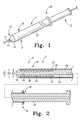
- FIG. 1is a perspective view of a delivery and deployment device according to an aspect of the present invention
- FIG. 2is a cross-sectional view of the device of FIG. 1 ;
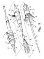
- FIG. 3is a perspective view of selected segments of a delivery and deployment device including a partially-deployed prosthesis
- FIG. 4is a cross-sectional view of the device of FIG. 3 ;
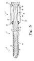
- FIG. 5is a cross-sectional view of a delivery and deployment device including an operating mechanism, according to an aspect of the invention.
- FIG. 6is a cross-sectional view of an alternate delivery and deployment device including an operating mechanism, according to an aspect of the invention.
- FIG. 7is a cross-sectional view of an alternate delivery and deployment device including an operating mechanism, according to an aspect of the invention.
- FIG. 8is a side elevational view of an operating mechanism including a mechanical conversion mechanism according to an aspect of the invention.
- FIG. 9Ais a cross-sectional view of a delivery and deployment device in a pre-deployment state
- FIG. 9Bis a cross-sectional view of a delivery and deployment device in a partially-deployed state
- FIG. 9Cis a cross-sectional view of a delivery and deployment device in a fully-deployed state.
- distal and distalshall denote a position, direction, or orientation that is generally toward the patient. Accordingly, the terms “proximal” and “proximally” shall denote a position, direction, or orientation that is generally away from the patient.
- FIGS. 1-3show various exemplary devices 1 for delivering and deploying an expandable endoluminal prosthesis 20 in a body lumen.
- the device 1comprises a prosthesis delivery section 2 and an external manipulation section 3 .
- the delivery section 2travels through the body lumen during the procedure and delivers the prosthesis to a desired deployment site.
- the external manipulation section 3stays outside of the body during the procedure.
- the external manipulation section 3can be manipulated by the operator to position and release or deploy the prosthesis 20 into the body lumen.
- the delivery and deployment device 1comprises a delivery catheter 10 and a sheath 12 .
- the delivery catheter 10 and the sheath 12are configured to selectively retain and release an expandable prosthesis 20 .
- the delivery catheter 10has a proximal end and a distal end.
- the distal end of the delivery cathetercomprises a dilator head 13 .
- the dilator head 13is distally tapered to provide for atraumatic insertion into the body lumen (not shown).
- a guidewire lumen 15extends longitudinally through the delivery catheter 10 between the proximal and distal ends.
- the delivery catheter 10is configured to receive a guidewire 17 via the guidewire lumen 15 as shown in FIG. 1 .
- the delivery catheter 10comprises a prosthesis receiving portion 16 and a prosthesis release portion 18 , as shown in FIG. 2 .
- the receiving portion 16is disposed on a distal portion of the delivery catheter and is configured to receive the prosthesis 20 in a radially compressed configuration.
- the receiving portion 16may comprise a catheter tube 22 having a longitudinally uniform external diameter D 1 .
- the release portion 18 of the delivery catheter 10is disposed generally proximally of the prosthesis 20 .
- the release portion 18can be manipulated, along with the sheath 12 , to selectively deliver and deploy the prosthesis 20 in the body lumen.
- the release portion 18may comprise a catheter tube 24 having a longitudinally uniform external diameter D 2 .
- Catheter tube 24may have a diameter D 2 that is greater than diameter D 1 .
- the release portion 18includes a distal-facing annular abutment surface 23 at the transition between catheter tubes 22 and 24 .
- the annular abutment surface 23faces the proximal end of the prosthesis 20 and is configured to contact the proximal end of the prosthesis 20 during deployment, allowing the delivery catheter 10 to push the prosthesis 20 distally as the sheath 12 is pulled proximally in relation thereto.
- the delivery catheter 10may comprise a single unitary structure as shown in FIG. 2 . Alternately, the delivery catheter 10 may comprise a plurality of slidably interconnected catheters 22 , 24 as shown in FIG. 3 .
- the sheath 12comprises an elongate tubular body having a proximal and distal end and a sheath lumen 14 .
- the sheath lumen 14has a generally constant diameter between the proximal and distal ends.
- the sheath 12extends proximally from the delivery section 2 to the user manipulation section 3 .
- the delivery catheter 10is slidably disposed within lumen 14 .
- the sheath 12releasably covers and retains the prosthesis 20 in a radially reduced configuration.
- the dilator head 13 and the sheath 20preferably form a generally smooth transition so as to prevent trauma to the body lumen during delivery and deployment.
- the distal end of the sheath 12travels within the body lumen during a procedure.
- the proximal end of the sheath 12is configured to remain outside of the body during the procedure and can be directly manipulated by the operator to deploy the prosthesis 20 .
- the sheath 12may have a length, as shown in FIGS. 3 and 4 , that is significantly greater than the length of the prosthesis 20 .
- the sheath 12may have a length that is two or more times greater than the length of the prosthesis 20 .
- the sheath 12may have a length that is generally equal to or greater than the length of the prosthesis.
- the sheath 12has a uniform internal diameter D 3 .
- the internal diameter D 3is generally equal to the external diameter D 2 of catheter tube 24 so that the inner surface of the sheath 12 slidingly engages the delivery catheter 10 .
- the sheathmay be made of any suitable biocompatible material, for example PTFE, nylon, or polyethylene.
- the sheathmay optionally comprise a flat wire coil (not shown) to provide the sheath with additional flexibility and kink-resistance.
- the prosthesis 20may comprise a stent graft having a plurality of self-expanding stents 32 .
- the stents 32cause the prosthesis 20 to expand during its release from the device 1 .
- the stents 32may cover and/or may be at least partially covered by a graft material.
- the prosthesis 20also may include an exposed self-expanding zigzag stent 34 for anchoring the prosthesis 20 in the body lumen.
- the zigzag stent 34may comprise barbs 36 that extend from the stent. When the zigzag stent 34 is released, the barbs 36 engage the surrounding lumen.
- Suitable graft configurationsinclude, but are not limited to films, coatings, sheets of biocompatible fabrics, non-woven materials and porous materials.
- suitable graft materialsinclude polyesters, such as poly(ethylene terephthalate), polylactide, polyglycolide and copolymers thereof; fluorinated polymers, such as polytetrafluoroethylene (PTFE), expanded PTFE and poly(vinylidene fluoride); polysiloxanes, including polydimethyl siloxane; and polyurethanes, including polyetherurethanes, polyurethane ureas, polyetherurethane ureas, polyurethanes containing carbonate linkages and polyurethanes containing siloxane segments.
- polyesterssuch as poly(ethylene terephthalate), polylactide, polyglycolide and copolymers thereof
- fluorinated polymerssuch as polytetrafluoroethylene (PTFE), expanded PTFE and poly(vinylidene fluoride
- Stents used in the present inventionmay be self-expanding or balloon-expandable.
- a balloon-expandable stent or stent portionmay be combined with a self-expanding stent or stent portion.
- Self-expanding stentscan be made of stainless steel, materials with elastic memory properties, such as NITINOL, or any other suitable material.
- a suitable self-expanding stentincludes Z-STENTS®, which are available from Cook, Incorporated, Bloomington, Ind. USA.
- Balloon-expandable stentsmay be made of various materials including, but not limited to, stainless steel (typically 316LSS, CoCr, Etc.).
- the prosthesis 20is retained in a radially reduced configuration between the delivery catheter 10 and the sheath 12 .
- the sheath 12is slidably disposed over the prosthesis 20 and the delivery catheter 10 in a proximal and a distal direction.
- the sheath 12may be slid proximally with respect to the delivery catheter 10 and the prosthesis 20 to expose the prosthesis.
- the operatorslides the sheath 12 proximally while applying distal pressure to the delivery catheter 10 via catheter tube 24 .
- Catheter tube 24pushes the prosthesis 20 distally via the annular abutment surface 23 while the sheath 12 slides proximally in relation thereto.
- the catheter tube 24pushes the prosthesis 20 distally from the receiving portion 16 and into the body lumen.
- the delivery and deployment device 1may further comprise a haemostatic sealing device 19 for controlling blood loss between the delivery catheter 10 and the sheath 12 during a procedure.
- FIGS. 3 and 4illustrate an exemplary haemostatic sealing device 19 .
- the device 19includes a haemostatic seal 25 and a clamping collar 27 that clamps the sheath 12 to the haemostatic seal 25 .
- the haemostatic seal 25may include a seal ring 29 which may be made of silicone.
- the seal ring 29engages the delivery catheter 10 and forms a tight haemostatic seal around catheter tube 24 .
- the tight seal between the seal ring 29 and the catheter tube 24creates an interference fit between the sealing device 19 and the delivery catheter 10 , thereby increasing the sliding resistance between the sheath 12 and the catheter 10 .
- the haemostatic sealing device 19may also include a side tube 30 that facilitates the introduction of medical reagents between the delivery catheter 10 and the sheath 12 .
- the delivery and deployment device 1may optionally include deployment control mechanisms 39 , 40 as shown in FIGS. 3 and 4 .
- Proximal control mechanism 39releasably retains the proximal end of the prosthesis 20 and distal control mechanism 40 releasably retains the distal end of the prosthesis 20 .
- Proximal control mechanism 39may comprise a trigger wire 41 that releasably couples the proximal end of the prosthesis 20 to the delivery catheter 10 .
- the distal control mechanism 40may comprise a trigger wire 42 that releasably couples the distal end of the prosthesis 20 to the delivery catheter 10 .
- the trigger wires 41 , 42extend proximally to the external manipulation section 3 where they are coupled to trigger release devices 43 , 44 .
- Trigger release devices 43 , 44are configured to selectively decouple the proximal and distal ends of the prosthesis from the delivery catheter 10 , respectively.
- Various prosthesis retention devices, configurations, and methods of useare disclosed in PCT Patent Publication Number WO 98/53761, previously incorporated by reference.
- FIG. 5shows an exemplary system including a delivery catheter 10 and a sheath 12 .
- a prosthesis 20may be radially retained between the delivery catheter 10 and the sheath 12 .
- the sheath 12is retracted proximally over the delivery catheter 10 to expose the prosthesis 20 .
- an operating mechanism 50may be provided to aid the operator in retracting the sheath 12 over the delivery catheter 10 .
- the operating mechanism 50is disposed in the user manipulation section 3 and may be disposed on the proximal end of the delivery catheter 10 as shown in FIG. 5 .
- the operating mechanism 50couples the sheath 12 to the delivery catheter 10 and is configured to pull the sheath 12 proximally with respect to the delivery catheter 10 and to push the delivery catheter 10 distally with respect to the sheath 12 .
- the operating mechanism 50comprises a longitudinally contractible element 56 .
- the contractible element 56has an expanded length and a contracted length, where the expanded length is greater than the contracted length.
- a proximal end 54 of the contractible element 56may be mechanically coupled to the delivery catheter 10 and a distal end 52 may be mechanically coupled to the sheath 12 .
- Contraction of the contractible element 56causes the sheath 12 to slide proximally in relation to the delivery catheter 10 and the delivery catheter 10 to slide distally in relation to the sheath 12 .
- the contractible element 56may comprise a contractible air vessel 58 .
- the air vessel 58includes an air chamber 59 and has an expanded configuration and a contracted configuration.
- a proximal end 54 of the air vessel 58is mechanically coupled to the delivery catheter 10 and a distal end 52 of the air vessel 58 is mechanically coupled to the sheath 12 .
- the operating mechanism 50further comprises a port 60 .
- Port 60is configured to provide pneumatic communication between an air pressure source (not shown) and the air chamber 59 .
- the operatorcauses the air vessel 58 to contract, for example by applying a sub-atmospheric pressure, or a vacuum to the air vessel 58 via port 60 .
- the air vessel 58may comprise a resilient tubular member 57 , as shown in FIG. 6 .
- the tubular member 57may be made of a flexible plastic material, for example rubber, thermoplastic elastomer, polyolefin, or a fluoropolymer material including, but not limited to polytetrafluoroethylene and fluoroethylene-propylene.
- the proximal end 54 of the tubular member 57is sealingly disposed about the delivery catheter 10 .
- the distal end 52 of the tubular member 57is sealingly disposed about the sheath 12 .
- the tubular member 57 and the delivery and deployment device 1define an annular air chamber 59 .
- the distal end 52 of the tubular member 57may be coupled to the sheath 12 via the haemostatic sealing device 19 .
- a pneumatic seal 69for example a v-ring seal, may be provided to seal the interface between the air chamber 59 and the haemostatic sealing device 19 .
- the operating mechanism 50further comprises a port 60 that is configured to provide pneumatic communication between a vacuum pressure source (not shown) and the air chamber 59 .
- the port 60may include a connector, for example a female luer for providing a connection with an air pressure source.
- the air vessel 58may comprise a bellows.
- the bellowspreferably has a generally circular transverse cross-section, but alternately may have a non-circular transverse cross-section, for example a polygonal cross-section.
- the term “bellows”shall mean a flexible contractible and/or expansible vessel, which may include, but does not require a pleated structure.
- a proximal end 54 of the bellowsis mechanically coupled to the delivery catheter 10 and a distal end 52 is mechanically coupled to the sheath 12 .
- the bellowsmay be constructed of any suitable material, for example metal, rubber, thermoplastic elastomer, polyolefin, or a fluoropolymer material including, but not limited to polytetrafluoroethylene and fluoroethylene-propylene.
- the bellowshas an exterior diameter and a wall thickness that will be selected according to the particular force requirements of the system. In general, the force exerted by the bellows will be proportional to the area of the inner, distal end of the bellows.
- An exemplary tubular bellowsmay comprise an exterior diameter between 1 inch and 3 inches. Alternately, the bellows may comprise an exterior diameter between 1.3 inches and 1.8 inches.
- An exemplary bellowsmay have a wall thickness of approximately 0.025 inches. The diameter and wall thickness may be greater or less depending on the particular requirements of the system.
- the operating mechanism 50may comprise an actuation switch 70 .
- the actuation switch 70is used to control the manner of deployment and is configured to selectively commence and halt contraction of the contractible element.
- the operating mechanism 50comprises a switch 70 that includes a reversibly sealable aperture 72 formed in the air line 75 between the port 60 and the air source.
- the switch 70When the switch 70 is closed, for example where the aperture 72 is occluded, the air vessel may be pressurized via port 60 .
- the switch 70is open, the aperture 72 prevents pneumatic communication between the air source and the air chamber 59 , thereby preventing the vessel 58 from contracting.
- the switch 70may be opened, relieving pressure in the air chamber 59 and causing an immediate halt in the retraction of the sheath 12 .
- a check valvemay be provided in series with the port 60 .
- a valveis preferable to prevent a compressed air vessel, for example a polymer bellows, from expanding when pneumatic communication is disrupted between the air source and the air chamber 59 (e.g., when the vacuum is turned off or when the switch 70 is opened).
- FIG. 7shows another operating mechanism 50 according to an aspect of the invention.
- the operating mechanism 50comprises a cylinder 80 and a piston 82 .
- Cylinder 80 and piston 82form a contractible air vessel 58 defining an air chamber 59 .
- the operating mechanism 50comprises a port 60 for providing pneumatic communication between a pressure source (not shown) and the air chamber 59 .
- the piston 82is mechanically coupled to the sheath 12 .
- the cylinder 80is mechanically coupled to the delivery catheter 10 .
- a vacuummay be drawn on the air chamber 59 , causing the piston 82 to slide proximally in the cylinder 80 .
- the piston 82pulls the sheath 12 proximally with respect to the delivery catheter 10 and the cylinder 80 pushes the delivery catheter 10 distally with respect to the sheath 12 .
- the contractible vessel 58causes the sheath 12 to retract over the delivery catheter 10 a maximum distance that is generally proportional to the difference between the expanded length and the contracted length of the vessel. For example, a bellows having a 10 inch expanded length and a 2 inch contracted length will be sufficient to retract sheath 12 over a distance of approximately 8 inches. In the embodiments previously shown, the ratio between sheath retraction distance and vessel contraction distance is approximately 1 to 1.
- FIG. 8illustrates another operating mechanism 50 according to an aspect of the present invention.
- the operating mechanism 50comprises a contractible air vessel 58 , for example a bellows.
- a proximal end 54 of the bellowsis mechanically coupled to the delivery catheter 10 and a distal end 52 of the bellows is mechanically coupled to the sheath 12 .
- the operating mechanism 50further comprises a conversion mechanism 90 disposed between the bellows and the sheath 12 .
- the conversion mechanism 90is configured to convert vessel contraction into sheath retraction.
- the conversion mechanism 90may include a linear gear 92 and a pinion 94 .
- the linear gear 92is connected to the bellows such that contraction and expansion of the bellows causes the linear gear 92 to slide proximally and distally, respectively.
- the linear gear 92drives the pinion 94 , which is operably connected to a pulley 96 .
- the pulley 96drives a retractable cable 98 that is connected to the sheath. In FIG. 8 , the cable 98 is connected to the sheath 12 via the haemostatic sealing device 19 .
- the linear gear 92slides proximally, causing the pinion 94 to rotate about axis A.
- pinion 94rotates, it drives pulley 96 , causing the pulley to rotate about axis A.
- the conversion mechanism 90converts vessel contraction into sheath retraction.
- the radii of the pulley and the pinioncan be varied to affect the ratio between sheath retraction and vessel contraction.
- the ratiowill increase.
- the conversion mechanism 90may provide a ratio that is less than or equal to 1 or a ratio that is greater than or equal to 1.
- the operating mechanism 50 in FIG. 8may be provided with a bellows having an expanded length of 2 inches that is configured to contract over a distance of approximately 1.2 inches.
- the gear ratio between pinion 94 and linear gear 92is configured so that pinion 94 revolves approximately 1.7 times about axis A during the contraction of the bellows, causing the pulley 96 to revolve approximately 1.7 times about axis A.
- the systemwill retract the cable 98 , and thus the sheath 12 over a distance of approximately 8 inches, based on a vessel contraction of 1.2 inches.
- the conversion mechanismprovides a ratio that is greater than 2 to 1, and more preferably greater than 4 to 1.
- a ratio of less than 1may be desirable where the maximum force provided by the air vessel is less than the force normally required to retract the sheath.
- the conversion mechanismmay be configured to decrease the effort required to retract the sheath, while correspondingly increasing the required air vessel contraction distance.
- the selection of appropriate gears and gear ratios to provide a particular mechanical advantagewill be readily understood by one of ordinary skill in the art.
- the conversion mechanismprovides a ratio of less than 0.8 to 1, less than 0.5 to 1, or less than 0.2 to 1.
- FIGS. 9A-9CA method of deploying a prosthesis 20 into a body lumen will now be described with reference to FIGS. 9A-9C .
- a guidewire 17is introduced into the body lumen and advanced until the tip is beyond the region into which the prosthesis 20 is to be deployed.
- the delivery and deployment device 1is then inserted into the body lumen over the guide wire 17 (as shown in FIG. 1 ) and positioned in the treatment area by radiographic techniques that are generally known in the art.
- the prosthesis 20is fully retained in the delivery and deployment device 1 in a radially-constrained configuration by the sheath 12 as shown in FIG. 9A .
- FIGS. 9A-9Cillustrate deployment using a bellows operating mechanism 50 as described above. It should be understood that the operating mechanism 50 could include any contractible element 56 within the scope of the present invention. Additionally, the operating mechanism 50 could comprise a mechanical conversion mechanism 90 for converting vessel contraction into sheath retraction.
- the operating mechanism 50is connected to a sub-atmospheric, or air vacuum pressure source (not shown) through port 60 via air line 75 .
- the pressure sourcecauses the bellows to contract. As the bellows contracts, it pulls the sheath 12 proximally over the delivery catheter 10 and the prosthesis 20 . As the sheath 12 retracts, the prosthesis 20 becomes exposed and is thereby allowed to expand into the body lumen, as shown in FIG. 9B .
- the delivery catheter 10is held steady relative to the sheath 12 during deployment.
- the operatormay manually fix the position of the delivery catheter 10 .
- a delivery fixture(not shown) may be provided to hold the delivery catheter 10 steady during deployment.
- the operatormay control the manner of deployment by varying the input from the pressure source during the procedure. To this end, the operator may manually adjust the pressure from the source. Additionally, the operating mechanism 50 may comprise an actuation switch 70 . To initiate retraction, the operator covers aperture 72 , thereby allowing pneumatic communication between the pressure source and the air chamber 59 . To halt retraction, the operator uncovers aperture 72 , thereby cutting off pneumatic communication between the pressure source and the air chamber 59 .
- FIG. 9Cshows the delivery and deployment device in a fully deployed state.
- the bellowsis in a contracted configuration, the sheath 12 is completely retracted from the prosthesis 20 , and the prosthesis 20 is expanded within the body lumen.
- the delivery and deployment device and the guide wiremay now be removed from the body lumen.
Landscapes
- Health & Medical Sciences (AREA)
- Engineering & Computer Science (AREA)
- Biomedical Technology (AREA)
- Cardiology (AREA)
- Oral & Maxillofacial Surgery (AREA)
- Transplantation (AREA)
- Heart & Thoracic Surgery (AREA)
- Vascular Medicine (AREA)
- Life Sciences & Earth Sciences (AREA)
- Animal Behavior & Ethology (AREA)
- General Health & Medical Sciences (AREA)
- Public Health (AREA)
- Veterinary Medicine (AREA)
- Media Introduction/Drainage Providing Device (AREA)
Abstract
Description
Claims (20)
Priority Applications (1)
| Application Number | Priority Date | Filing Date | Title |
|---|---|---|---|
| US11/764,969US8118853B2 (en) | 2006-06-19 | 2007-06-19 | Prosthesis delivery and deployment device |
Applications Claiming Priority (2)
| Application Number | Priority Date | Filing Date | Title |
|---|---|---|---|
| US81476006P | 2006-06-19 | 2006-06-19 | |
| US11/764,969US8118853B2 (en) | 2006-06-19 | 2007-06-19 | Prosthesis delivery and deployment device |
Publications (2)
| Publication Number | Publication Date |
|---|---|
| US20070293934A1 US20070293934A1 (en) | 2007-12-20 |
| US8118853B2true US8118853B2 (en) | 2012-02-21 |
Family
ID=38862558
Family Applications (1)
| Application Number | Title | Priority Date | Filing Date |
|---|---|---|---|
| US11/764,969Active2030-07-22US8118853B2 (en) | 2006-06-19 | 2007-06-19 | Prosthesis delivery and deployment device |
Country Status (1)
| Country | Link |
|---|---|
| US (1) | US8118853B2 (en) |
Cited By (18)
| Publication number | Priority date | Publication date | Assignee | Title |
|---|---|---|---|---|
| US20090275971A1 (en)* | 2007-10-30 | 2009-11-05 | Boston Scientific Scimed, Inc. | Energy activated preloaded detachment mechanisms for implantable devices |
| US20130304181A1 (en)* | 2012-05-09 | 2013-11-14 | Michael L. Green | Catheter having hydraulic actuator with tandem chambers |
| US8906011B2 (en) | 2007-11-16 | 2014-12-09 | Kardium Inc. | Medical device for use in bodily lumens, for example an atrium |
| US8920411B2 (en) | 2006-06-28 | 2014-12-30 | Kardium Inc. | Apparatus and method for intra-cardiac mapping and ablation |
| US9119633B2 (en) | 2006-06-28 | 2015-09-01 | Kardium Inc. | Apparatus and method for intra-cardiac mapping and ablation |
| US9452016B2 (en) | 2011-01-21 | 2016-09-27 | Kardium Inc. | Catheter system |
| US9480525B2 (en) | 2011-01-21 | 2016-11-01 | Kardium, Inc. | High-density electrode-based medical device system |
| US9492227B2 (en) | 2011-01-21 | 2016-11-15 | Kardium Inc. | Enhanced medical device for use in bodily cavities, for example an atrium |
| USD777926S1 (en) | 2012-01-20 | 2017-01-31 | Kardium Inc. | Intra-cardiac procedure device |
| USD777925S1 (en) | 2012-01-20 | 2017-01-31 | Kardium Inc. | Intra-cardiac procedure device |
| US10028783B2 (en) | 2006-06-28 | 2018-07-24 | Kardium Inc. | Apparatus and method for intra-cardiac mapping and ablation |
| US10039659B2 (en) | 2012-05-09 | 2018-08-07 | Abbott Cardiovascular Systems Inc. | Catheter having hydraulic actuator |
| US10327932B2 (en) | 2013-03-12 | 2019-06-25 | Abbott Cardiovascular Systems Inc. | Catheter having hydraulic actuator and locking system |
| US10420662B2 (en) | 2013-03-12 | 2019-09-24 | Abbott Cardiovascular Systems Inc. | Catheter having movable tubular structure and proximal stopper |
| US10531971B2 (en) | 2013-03-12 | 2020-01-14 | Abbott Cardiovascular System Inc. | Balloon catheter having hydraulic actuator |
| US10675164B2 (en) | 2012-05-09 | 2020-06-09 | Abbott Cardiovascular Systems Inc. | Catheter having dual balloon hydraulic actuator |
| US11259867B2 (en) | 2011-01-21 | 2022-03-01 | Kardium Inc. | High-density electrode-based medical device system |
| US11389232B2 (en) | 2006-06-28 | 2022-07-19 | Kardium Inc. | Apparatus and method for intra-cardiac mapping and ablation |
Families Citing this family (13)
| Publication number | Priority date | Publication date | Assignee | Title |
|---|---|---|---|---|
| JP5181211B2 (en)* | 2005-12-23 | 2013-04-10 | クック・メディカル・テクノロジーズ・リミテッド・ライアビリティ・カンパニー | Trigger wire release mechanism and introducer for prosthesis including the same |
| US9119742B2 (en)* | 2007-07-16 | 2015-09-01 | Cook Medical Technologies Llc | Prosthesis delivery and deployment device |
| JP2013535259A (en)* | 2010-07-21 | 2013-09-12 | クック メディカル テクノロジーズ エルエルシー | Control mechanism for stent delivery system |
| US9364358B2 (en) | 2012-07-27 | 2016-06-14 | Medinol Ltd. | Catheter with retractable cover and pressurized fluid |
| US11399842B2 (en) | 2013-03-13 | 2022-08-02 | Conformal Medical, Inc. | Devices and methods for excluding the left atrial appendage |
| JP6423851B2 (en) | 2013-03-13 | 2018-11-14 | アーロン・ヴィ・カプラン | Device for emptying the left atrial appendage |
| EP3043755B1 (en)* | 2013-09-12 | 2022-10-19 | St. Jude Medical, Cardiology Division, Inc. | Atraumatic interface in an implant delivery device |
| US11426172B2 (en) | 2016-10-27 | 2022-08-30 | Conformal Medical, Inc. | Devices and methods for excluding the left atrial appendage |
| WO2018081466A2 (en) | 2016-10-27 | 2018-05-03 | Conformal Medical, Inc. | Devices and methods for excluding the left atrial appendage |
| US10575950B2 (en)* | 2017-04-18 | 2020-03-03 | Twelve, Inc. | Hydraulic systems for delivering prosthetic heart valve devices and associated methods |
| US10406012B2 (en)* | 2017-04-26 | 2019-09-10 | Medtronic Vascular, Inc. | Mechanical delivery systems for an endovascular device |
| US12268394B2 (en)* | 2019-02-08 | 2025-04-08 | Conformal Medical, Inc. | Devices and methods for excluding the left atrial appendage |
| US12144508B2 (en) | 2019-02-08 | 2024-11-19 | Conformal Medical, Inc. | Devices and methods for excluding the left atrial appendage |
Citations (42)
| Publication number | Priority date | Publication date | Assignee | Title |
|---|---|---|---|---|
| US4562596A (en) | 1984-04-25 | 1986-01-07 | Elliot Kornberg | Aortic graft, device and method for performing an intraluminal abdominal aortic aneurysm repair |
| US4665918A (en) | 1986-01-06 | 1987-05-19 | Garza Gilbert A | Prosthesis system and method |
| US4921484A (en) | 1988-07-25 | 1990-05-01 | Cordis Corporation | Mesh balloon catheter device |
| US5078720A (en) | 1990-05-02 | 1992-01-07 | American Medical Systems, Inc. | Stent placement instrument and method |
| US5092877A (en) | 1988-09-01 | 1992-03-03 | Corvita Corporation | Radially expandable endoprosthesis |
| US5201757A (en) | 1992-04-03 | 1993-04-13 | Schneider (Usa) Inc. | Medial region deployment of radially self-expanding stents |
| US5380304A (en) | 1991-08-07 | 1995-01-10 | Cook Incorporated | Flexible, kink-resistant, introducer sheath and method of manufacture |
| WO1995011055A1 (en) | 1993-10-22 | 1995-04-27 | Scimed Lifesystems, Inc. | Improved stent delivery apparatus and method |
| US5415664A (en) | 1994-03-30 | 1995-05-16 | Corvita Corporation | Method and apparatus for introducing a stent or a stent-graft |
| US5445646A (en) | 1993-10-22 | 1995-08-29 | Scimed Lifesystems, Inc. | Single layer hydraulic sheath stent delivery apparatus and method |
| US5534007A (en) | 1995-05-18 | 1996-07-09 | Scimed Life Systems, Inc. | Stent deployment catheter with collapsible sheath |
| US5626603A (en) | 1994-10-05 | 1997-05-06 | Fogazzi Di Ventureli Andrea & C. S.N.C. | Hydraulic stent inserter |
| US5690644A (en) | 1992-12-30 | 1997-11-25 | Schneider (Usa) Inc. | Apparatus for deploying body implantable stent |
| US5817101A (en) | 1997-03-13 | 1998-10-06 | Schneider (Usa) Inc | Fluid actuated stent delivery system |
| WO1998053761A1 (en) | 1997-05-26 | 1998-12-03 | William A. Cook Australia Pty. Ltd. | A prosthesis and a method and means of deploying a prosthesis |
| US5928197A (en)* | 1993-11-24 | 1999-07-27 | Liebel-Flarsheim Company | Controlling plunger drives for fluid injections in animals |
| US5968052A (en)* | 1996-11-27 | 1999-10-19 | Scimed Life Systems Inc. | Pull back stent delivery system with pistol grip retraction handle |
| EP0696447B1 (en) | 1994-08-12 | 2000-01-19 | Cardiovascular Concepts, Inc. | Apparatus for deployment release of intraluminal prostheses |
| US6113608A (en)* | 1998-11-20 | 2000-09-05 | Scimed Life Systems, Inc. | Stent delivery device |
| US6152931A (en)* | 1998-02-16 | 2000-11-28 | B. Braun Celsa | Medical device comprising a rod equipped with a means for absorbing axial stresses |
| US6206888B1 (en) | 1997-10-01 | 2001-03-27 | Scimed Life Systems, Inc. | Stent delivery system using shape memory retraction |
| US6254611B1 (en) | 1996-09-27 | 2001-07-03 | Scimed Life Systems, Inc. | Stent deployment catheter with midshaft seal |
| US20010034514A1 (en) | 2000-03-23 | 2001-10-25 | Cook Incorporated | Introducer sheath |
| US20020045929A1 (en) | 2000-10-13 | 2002-04-18 | Juan-Carlos Diaz | Stent delivery system with hydraulic deployment |
| US6514261B1 (en) | 1998-09-30 | 2003-02-04 | Impra, Inc. | Delivery mechanism for implantable stent |
| US20030109886A1 (en) | 2001-06-27 | 2003-06-12 | Martin Keegan | Catheter |
| US6626934B2 (en) | 1999-06-14 | 2003-09-30 | Scimed Life Systems, Inc. | Stent delivery system |
| US6669716B1 (en) | 1998-03-31 | 2003-12-30 | Salviac Limited | Delivery catheter |
| US20040098079A1 (en) | 2002-06-28 | 2004-05-20 | Cook Incorporated | Thoracic aortic stent graft deployment device |
| US20040106974A1 (en) | 2002-06-28 | 2004-06-03 | Cook Incorporated | Thoracic introducer |
| US20040127912A1 (en) | 2002-12-31 | 2004-07-01 | Dmitry Rabkin | Stent delivery system |
| US20040133264A1 (en) | 2000-02-04 | 2004-07-08 | Moore Scott T. | Stent introducer apparatus |
| US6858034B1 (en) | 1999-05-20 | 2005-02-22 | Scimed Life Systems, Inc. | Stent delivery system for prevention of kinking, and method of loading and using same |
| US20050060018A1 (en) | 2003-09-16 | 2005-03-17 | Cook Incorporated | Prosthesis deployment system |
| US20050085890A1 (en) | 2003-10-15 | 2005-04-21 | Cook Incorporated | Prosthesis deployment system retention device |
| US20050090887A1 (en) | 2003-10-22 | 2005-04-28 | Pryor Jack D. | Delivery system for long self-expanding stents |
| US6911039B2 (en) | 2002-04-23 | 2005-06-28 | Medtronic Vascular, Inc. | Integrated mechanical handle with quick slide mechanism |
| US20050273151A1 (en) | 2004-06-04 | 2005-12-08 | John Fulkerson | Stent delivery system |
| US20060282152A1 (en)* | 2005-06-14 | 2006-12-14 | Dagmar Beyerlein | Delivery system for a device such as a stent |
| US20060282150A1 (en)* | 2005-06-08 | 2006-12-14 | Xtent, Inc. | Devices and methods for operating and controlling interventional apparatus |
| US20070060999A1 (en) | 2005-08-17 | 2007-03-15 | Michael Randall | Variable speed stent delivery system |
| US20070233222A1 (en)* | 2006-02-21 | 2007-10-04 | Med Institute, Inc. | Split sheath deployment system |
- 2007
- 2007-06-19USUS11/764,969patent/US8118853B2/enactiveActive
Patent Citations (48)
| Publication number | Priority date | Publication date | Assignee | Title |
|---|---|---|---|---|
| US4562596A (en) | 1984-04-25 | 1986-01-07 | Elliot Kornberg | Aortic graft, device and method for performing an intraluminal abdominal aortic aneurysm repair |
| US4665918A (en) | 1986-01-06 | 1987-05-19 | Garza Gilbert A | Prosthesis system and method |
| US4921484A (en) | 1988-07-25 | 1990-05-01 | Cordis Corporation | Mesh balloon catheter device |
| US5092877A (en) | 1988-09-01 | 1992-03-03 | Corvita Corporation | Radially expandable endoprosthesis |
| US5078720A (en) | 1990-05-02 | 1992-01-07 | American Medical Systems, Inc. | Stent placement instrument and method |
| US5380304A (en) | 1991-08-07 | 1995-01-10 | Cook Incorporated | Flexible, kink-resistant, introducer sheath and method of manufacture |
| US5201757A (en) | 1992-04-03 | 1993-04-13 | Schneider (Usa) Inc. | Medial region deployment of radially self-expanding stents |
| US5690644A (en) | 1992-12-30 | 1997-11-25 | Schneider (Usa) Inc. | Apparatus for deploying body implantable stent |
| WO1995011055A1 (en) | 1993-10-22 | 1995-04-27 | Scimed Lifesystems, Inc. | Improved stent delivery apparatus and method |
| US5445646A (en) | 1993-10-22 | 1995-08-29 | Scimed Lifesystems, Inc. | Single layer hydraulic sheath stent delivery apparatus and method |
| US5928197A (en)* | 1993-11-24 | 1999-07-27 | Liebel-Flarsheim Company | Controlling plunger drives for fluid injections in animals |
| US5415664A (en) | 1994-03-30 | 1995-05-16 | Corvita Corporation | Method and apparatus for introducing a stent or a stent-graft |
| EP0696447B1 (en) | 1994-08-12 | 2000-01-19 | Cardiovascular Concepts, Inc. | Apparatus for deployment release of intraluminal prostheses |
| US5626603A (en) | 1994-10-05 | 1997-05-06 | Fogazzi Di Ventureli Andrea & C. S.N.C. | Hydraulic stent inserter |
| US5534007A (en) | 1995-05-18 | 1996-07-09 | Scimed Life Systems, Inc. | Stent deployment catheter with collapsible sheath |
| US6254611B1 (en) | 1996-09-27 | 2001-07-03 | Scimed Life Systems, Inc. | Stent deployment catheter with midshaft seal |
| US5968052A (en)* | 1996-11-27 | 1999-10-19 | Scimed Life Systems Inc. | Pull back stent delivery system with pistol grip retraction handle |
| US6056759A (en) | 1997-03-13 | 2000-05-02 | Schneider (Usa) Inc. | Fluid actuated stent delivery system |
| US6605109B2 (en) | 1997-03-13 | 2003-08-12 | Scimed Life Systems, Inc | Fluid actuated stent delivery system |
| US5817101A (en) | 1997-03-13 | 1998-10-06 | Schneider (Usa) Inc | Fluid actuated stent delivery system |
| WO1998053761A1 (en) | 1997-05-26 | 1998-12-03 | William A. Cook Australia Pty. Ltd. | A prosthesis and a method and means of deploying a prosthesis |
| US6579297B2 (en) | 1997-10-01 | 2003-06-17 | Scimed Life Systems, Inc. | Stent delivery system using shape memory retraction |
| US6206888B1 (en) | 1997-10-01 | 2001-03-27 | Scimed Life Systems, Inc. | Stent delivery system using shape memory retraction |
| US20010012944A1 (en) | 1997-10-01 | 2001-08-09 | Bicek Andrew D. | Stent delivery system using shape memory retraction |
| US6152931A (en)* | 1998-02-16 | 2000-11-28 | B. Braun Celsa | Medical device comprising a rod equipped with a means for absorbing axial stresses |
| US6669716B1 (en) | 1998-03-31 | 2003-12-30 | Salviac Limited | Delivery catheter |
| US7122050B2 (en) | 1998-09-30 | 2006-10-17 | Bard Peripheral Vascular, Inc. | Delivery mechanism for implantable stent |
| US6514261B1 (en) | 1998-09-30 | 2003-02-04 | Impra, Inc. | Delivery mechanism for implantable stent |
| US6113608A (en)* | 1998-11-20 | 2000-09-05 | Scimed Life Systems, Inc. | Stent delivery device |
| US6858034B1 (en) | 1999-05-20 | 2005-02-22 | Scimed Life Systems, Inc. | Stent delivery system for prevention of kinking, and method of loading and using same |
| US6626934B2 (en) | 1999-06-14 | 2003-09-30 | Scimed Life Systems, Inc. | Stent delivery system |
| US20040133264A1 (en) | 2000-02-04 | 2004-07-08 | Moore Scott T. | Stent introducer apparatus |
| US20010034514A1 (en) | 2000-03-23 | 2001-10-25 | Cook Incorporated | Introducer sheath |
| US20020045929A1 (en) | 2000-10-13 | 2002-04-18 | Juan-Carlos Diaz | Stent delivery system with hydraulic deployment |
| US20030109886A1 (en) | 2001-06-27 | 2003-06-12 | Martin Keegan | Catheter |
| US6911039B2 (en) | 2002-04-23 | 2005-06-28 | Medtronic Vascular, Inc. | Integrated mechanical handle with quick slide mechanism |
| US20040098079A1 (en) | 2002-06-28 | 2004-05-20 | Cook Incorporated | Thoracic aortic stent graft deployment device |
| US20040106974A1 (en) | 2002-06-28 | 2004-06-03 | Cook Incorporated | Thoracic introducer |
| US20040127912A1 (en) | 2002-12-31 | 2004-07-01 | Dmitry Rabkin | Stent delivery system |
| US6849084B2 (en) | 2002-12-31 | 2005-02-01 | Intek Technology L.L.C. | Stent delivery system |
| US20050060018A1 (en) | 2003-09-16 | 2005-03-17 | Cook Incorporated | Prosthesis deployment system |
| US20050085890A1 (en) | 2003-10-15 | 2005-04-21 | Cook Incorporated | Prosthesis deployment system retention device |
| US20050090887A1 (en) | 2003-10-22 | 2005-04-28 | Pryor Jack D. | Delivery system for long self-expanding stents |
| US20050273151A1 (en) | 2004-06-04 | 2005-12-08 | John Fulkerson | Stent delivery system |
| US20060282150A1 (en)* | 2005-06-08 | 2006-12-14 | Xtent, Inc. | Devices and methods for operating and controlling interventional apparatus |
| US20060282152A1 (en)* | 2005-06-14 | 2006-12-14 | Dagmar Beyerlein | Delivery system for a device such as a stent |
| US20070060999A1 (en) | 2005-08-17 | 2007-03-15 | Michael Randall | Variable speed stent delivery system |
| US20070233222A1 (en)* | 2006-02-21 | 2007-10-04 | Med Institute, Inc. | Split sheath deployment system |
Cited By (62)
| Publication number | Priority date | Publication date | Assignee | Title |
|---|---|---|---|---|
| US9119634B2 (en) | 2006-06-28 | 2015-09-01 | Kardium Inc. | Apparatus and method for intra-cardiac mapping and ablation |
| US10820941B2 (en) | 2006-06-28 | 2020-11-03 | Kardium Inc. | Apparatus and method for intra-cardiac mapping and ablation |
| US8920411B2 (en) | 2006-06-28 | 2014-12-30 | Kardium Inc. | Apparatus and method for intra-cardiac mapping and ablation |
| US10828093B2 (en) | 2006-06-28 | 2020-11-10 | Kardium Inc. | Apparatus and method for intra-cardiac mapping and ablation |
| US9119633B2 (en) | 2006-06-28 | 2015-09-01 | Kardium Inc. | Apparatus and method for intra-cardiac mapping and ablation |
| US11389232B2 (en) | 2006-06-28 | 2022-07-19 | Kardium Inc. | Apparatus and method for intra-cardiac mapping and ablation |
| US10028783B2 (en) | 2006-06-28 | 2018-07-24 | Kardium Inc. | Apparatus and method for intra-cardiac mapping and ablation |
| US10828094B2 (en) | 2006-06-28 | 2020-11-10 | Kardium Inc. | Apparatus and method for intra-cardiac mapping and ablation |
| US9987084B2 (en) | 2006-06-28 | 2018-06-05 | Kardium Inc. | Apparatus and method for intra-cardiac mapping and ablation |
| US9987083B2 (en) | 2006-06-28 | 2018-06-05 | Kardium Inc. | Apparatus and method for intra-cardiac mapping and ablation |
| US11399890B2 (en) | 2006-06-28 | 2022-08-02 | Kardium Inc. | Apparatus and method for intra-cardiac mapping and ablation |
| US11389231B2 (en) | 2006-06-28 | 2022-07-19 | Kardium Inc. | Apparatus and method for intra-cardiac mapping and ablation |
| US20090275971A1 (en)* | 2007-10-30 | 2009-11-05 | Boston Scientific Scimed, Inc. | Energy activated preloaded detachment mechanisms for implantable devices |
| US11633231B2 (en) | 2007-11-16 | 2023-04-25 | Kardium Inc. | Medical device for use in bodily lumens, for example an atrium |
| US11432874B2 (en) | 2007-11-16 | 2022-09-06 | Kardium Inc. | Medical device for use in bodily lumens, for example an atrium |
| US11304751B2 (en) | 2007-11-16 | 2022-04-19 | Kardium Inc. | Medical device for use in bodily lumens, for example an atrium |
| US9585717B2 (en) | 2007-11-16 | 2017-03-07 | Kardium Inc. | Medical device for use in bodily lumens, for example an atrium |
| US9603661B2 (en) | 2007-11-16 | 2017-03-28 | Kardium Inc. | Medical device for use in bodily lumens, for example an atrium |
| US11076913B2 (en) | 2007-11-16 | 2021-08-03 | Kardium Inc. | Medical device for use in bodily lumens, for example an atrium |
| US9750569B2 (en) | 2007-11-16 | 2017-09-05 | Kardium Inc. | Medical device for use in bodily lumens, for example an atrium |
| US9820810B2 (en) | 2007-11-16 | 2017-11-21 | Kardium Inc. | Medical device for use in bodily lumens, for example an atrium |
| US9839474B2 (en) | 2007-11-16 | 2017-12-12 | Kardium Inc. | Medical device for use in bodily lumens, for example an atrium |
| US9877779B2 (en) | 2007-11-16 | 2018-01-30 | Kardium Inc. | Medical device for use in bodily lumens, for example an atrium |
| US11413091B2 (en) | 2007-11-16 | 2022-08-16 | Kardium Inc. | Medical device for use in bodily lumens, for example an atrium |
| US11331141B2 (en) | 2007-11-16 | 2022-05-17 | Kardium Inc. | Medical device for use in bodily lumens, for example an atrium |
| US11751940B2 (en) | 2007-11-16 | 2023-09-12 | Kardium Inc. | Medical device for use in bodily lumens, for example an atrium |
| US10828096B2 (en) | 2007-11-16 | 2020-11-10 | Kardium Inc. | Medical device for use in bodily lumens, for example an atrium |
| US10828095B2 (en) | 2007-11-16 | 2020-11-10 | Kardium Inc. | Medical device for use in bodily lumens, for example an atrium |
| US8932287B2 (en) | 2007-11-16 | 2015-01-13 | Kardium Inc. | Medical device for use in bodily lumens, for example an atrium |
| US8906011B2 (en) | 2007-11-16 | 2014-12-09 | Kardium Inc. | Medical device for use in bodily lumens, for example an atrium |
| US10499986B2 (en) | 2007-11-16 | 2019-12-10 | Kardium Inc. | Medical device for use in bodily lumens, for example an atrium |
| US10828097B2 (en) | 2007-11-16 | 2020-11-10 | Kardium Inc. | Medical device for use in bodily lumens, for example an atrium |
| US10828098B2 (en) | 2007-11-16 | 2020-11-10 | Kardium Inc. | Medical device for use in bodily lumens, for example an atrium |
| US11801091B2 (en) | 2007-11-16 | 2023-10-31 | Kardium Inc. | Medical device for use in bodily lumens, for example an atrium |
| US10485608B2 (en) | 2011-01-21 | 2019-11-26 | Kardium Inc. | Catheter system |
| US9492228B2 (en) | 2011-01-21 | 2016-11-15 | Kardium Inc. | Enhanced medical device for use in bodily cavities, for example an atrium |
| US12383325B2 (en) | 2011-01-21 | 2025-08-12 | Kardium Inc. | Enhanced medical device for use in bodily cavities, for example an atrium |
| US12349955B2 (en) | 2011-01-21 | 2025-07-08 | Kardium Inc. | Enhanced medical device for use in bodily cavities, for example an atrium |
| US12178490B2 (en) | 2011-01-21 | 2024-12-31 | Kardium Inc. | Enhanced medical device for use in bodily cavities, for example an atrium |
| US12059202B2 (en) | 2011-01-21 | 2024-08-13 | Kardium Inc. | Catheter system |
| US9675401B2 (en) | 2011-01-21 | 2017-06-13 | Kardium Inc. | Enhanced medical device for use in bodily cavities, for example an atrium |
| US11259867B2 (en) | 2011-01-21 | 2022-03-01 | Kardium Inc. | High-density electrode-based medical device system |
| US11298173B2 (en) | 2011-01-21 | 2022-04-12 | Kardium Inc. | Enhanced medical device for use in bodily cavities, for example an atrium |
| US11896295B2 (en) | 2011-01-21 | 2024-02-13 | Kardium Inc. | High-density electrode-based medical device system |
| US9452016B2 (en) | 2011-01-21 | 2016-09-27 | Kardium Inc. | Catheter system |
| US11350989B2 (en) | 2011-01-21 | 2022-06-07 | Kardium Inc. | Catheter system |
| US9526573B2 (en) | 2011-01-21 | 2016-12-27 | Kardium Inc. | Enhanced medical device for use in bodily cavities, for example an atrium |
| US11607261B2 (en) | 2011-01-21 | 2023-03-21 | Kardium Inc. | Enhanced medical device for use in bodily cavities, for example an atrium |
| US11399881B2 (en) | 2011-01-21 | 2022-08-02 | Kardium Inc. | Enhanced medical device for use in bodily cavities, for example an atrium |
| US9492227B2 (en) | 2011-01-21 | 2016-11-15 | Kardium Inc. | Enhanced medical device for use in bodily cavities, for example an atrium |
| US9486273B2 (en) | 2011-01-21 | 2016-11-08 | Kardium Inc. | High-density electrode-based medical device system |
| US9480525B2 (en) | 2011-01-21 | 2016-11-01 | Kardium, Inc. | High-density electrode-based medical device system |
| US11596463B2 (en) | 2011-01-21 | 2023-03-07 | Kardium Inc. | Enhanced medical device for use in bodily cavities, for example an atrium |
| USD777926S1 (en) | 2012-01-20 | 2017-01-31 | Kardium Inc. | Intra-cardiac procedure device |
| USD777925S1 (en) | 2012-01-20 | 2017-01-31 | Kardium Inc. | Intra-cardiac procedure device |
| US10675164B2 (en) | 2012-05-09 | 2020-06-09 | Abbott Cardiovascular Systems Inc. | Catheter having dual balloon hydraulic actuator |
| US9271855B2 (en)* | 2012-05-09 | 2016-03-01 | Abbott Cardiovascular Systems Inc. | Catheter having hydraulic actuator with tandem chambers |
| US20130304181A1 (en)* | 2012-05-09 | 2013-11-14 | Michael L. Green | Catheter having hydraulic actuator with tandem chambers |
| US10039659B2 (en) | 2012-05-09 | 2018-08-07 | Abbott Cardiovascular Systems Inc. | Catheter having hydraulic actuator |
| US10327932B2 (en) | 2013-03-12 | 2019-06-25 | Abbott Cardiovascular Systems Inc. | Catheter having hydraulic actuator and locking system |
| US10420662B2 (en) | 2013-03-12 | 2019-09-24 | Abbott Cardiovascular Systems Inc. | Catheter having movable tubular structure and proximal stopper |
| US10531971B2 (en) | 2013-03-12 | 2020-01-14 | Abbott Cardiovascular System Inc. | Balloon catheter having hydraulic actuator |
Also Published As
| Publication number | Publication date |
|---|---|
| US20070293934A1 (en) | 2007-12-20 |
Similar Documents
| Publication | Publication Date | Title |
|---|---|---|
| US8118853B2 (en) | Prosthesis delivery and deployment device | |
| EP2178470B1 (en) | Prosthesis delivery and deployment device | |
| US10456285B2 (en) | Split sheath deployment system | |
| EP2765959B1 (en) | Stent delivery, repositioning, and removal system | |
| JP5181211B2 (en) | Trigger wire release mechanism and introducer for prosthesis including the same | |
| EP0862384B1 (en) | Endoluminal prosthesis deployment device for use with prostheses of variable length and having retraction ability | |
| JP5927618B2 (en) | Tip release controlled stent graft delivery system and method | |
| US5683451A (en) | Apparatus and methods for deployment release of intraluminal prostheses | |
| US7666219B2 (en) | Prosthesis deployment system retention device | |
| US20090099638A1 (en) | Motorized deployment system | |
| US20080228255A1 (en) | Positionable Stent-Graft Delivery System and Method | |
| US20080114435A1 (en) | Flexible delivery system | |
| CN105025848A (en) | Endoprosthetic Delivery System with Deployment Aid | |
| US8419783B2 (en) | Graft deployment assist tool | |
| US20100222862A1 (en) | Stent, Stent Graft and Other Implantable Assemblies |
Legal Events
| Date | Code | Title | Description |
|---|---|---|---|
| AS | Assignment | Owner name:MED INSTITUTE, INC., INDIANA Free format text:ASSIGNMENT OF ASSIGNORS INTEREST;ASSIGNOR:GREWE, DAVID D.;REEL/FRAME:019635/0953 Effective date:20070712 | |
| AS | Assignment | Owner name:COOK MEDICAL TECHNOLOGIES LLC, INDIANA Free format text:ASSIGNMENT OF ASSIGNORS INTEREST;ASSIGNOR:MED INSTITUTE, INC.;REEL/FRAME:027539/0212 Effective date:20120110 | |
| STCF | Information on status: patent grant | Free format text:PATENTED CASE | |
| FPAY | Fee payment | Year of fee payment:4 | |
| MAFP | Maintenance fee payment | Free format text:PAYMENT OF MAINTENANCE FEE, 8TH YEAR, LARGE ENTITY (ORIGINAL EVENT CODE: M1552); ENTITY STATUS OF PATENT OWNER: LARGE ENTITY Year of fee payment:8 | |
| MAFP | Maintenance fee payment | Free format text:PAYMENT OF MAINTENANCE FEE, 12TH YEAR, LARGE ENTITY (ORIGINAL EVENT CODE: M1553); ENTITY STATUS OF PATENT OWNER: LARGE ENTITY Year of fee payment:12 | |
| AS | Assignment | Owner name:WILMINGTON TRUST, NATIONAL ASSOCIATION, AS COLLATERAL AGENT, DELAWARE Free format text:SECURITY INTEREST;ASSIGNOR:COOK MEDICAL TECHNOLOGIES LLC;REEL/FRAME:066700/0277 Effective date:20240227 |