US8118790B2 - Battery operated surgical hand piece with disposable end - Google Patents
Battery operated surgical hand piece with disposable endDownload PDFInfo
- Publication number
- US8118790B2 US8118790B2US12/443,898US44389807AUS8118790B2US 8118790 B2US8118790 B2US 8118790B2US 44389807 AUS44389807 AUS 44389807AUS 8118790 B2US8118790 B2US 8118790B2
- Authority
- US
- United States
- Prior art keywords
- plunger
- tip segment
- limited reuse
- reuse assembly
- dispensing chamber
- Prior art date
- Legal status (The legal status is an assumption and is not a legal conclusion. Google has not performed a legal analysis and makes no representation as to the accuracy of the status listed.)
- Expired - Fee Related, expires
Links
- 239000000126substanceSubstances0.000claimsabstractdescription59
- 238000002347injectionMethods0.000claimsabstractdescription10
- 239000007924injectionSubstances0.000claimsabstractdescription10
- 239000003814drugSubstances0.000claimsdescription62
- 229940079593drugDrugs0.000claimsdescription62
- 238000012377drug deliveryMethods0.000claimsdescription48
- 230000007246mechanismEffects0.000claimsdescription18
- 230000006870functionEffects0.000claimsdescription8
- 238000011109contaminationMethods0.000claimsdescription3
- 239000004065semiconductorSubstances0.000claimsdescription3
- 239000012530fluidSubstances0.000description12
- 238000000034methodMethods0.000description10
- 238000010586diagramMethods0.000description9
- 230000004044responseEffects0.000description6
- 238000010992refluxMethods0.000description4
- 238000012546transferMethods0.000description4
- OKKJLVBELUTLKV-UHFFFAOYSA-NMethanolChemical compoundOCOKKJLVBELUTLKV-UHFFFAOYSA-N0.000description3
- 230000005672electromagnetic fieldEffects0.000description3
- 239000000446fuelSubstances0.000description3
- 239000007788liquidSubstances0.000description3
- 230000008569processEffects0.000description3
- 208000005590Choroidal NeovascularizationDiseases0.000description2
- 206010060823Choroidal neovascularisationDiseases0.000description2
- 241000701022CytomegalovirusSpecies0.000description2
- 206010038910RetinitisDiseases0.000description2
- 206010064930age-related macular degenerationDiseases0.000description2
- 239000005441auroraSubstances0.000description2
- 230000008901benefitEffects0.000description2
- 210000004204blood vesselAnatomy0.000description2
- 238000004891communicationMethods0.000description2
- 239000004020conductorSubstances0.000description2
- 230000001419dependent effectEffects0.000description2
- 201000010099diseaseDiseases0.000description2
- 208000037265diseases, disorders, signs and symptomsDiseases0.000description2
- 238000006073displacement reactionMethods0.000description2
- 238000010438heat treatmentMethods0.000description2
- 208000002780macular degenerationDiseases0.000description2
- 238000001356surgical procedureMethods0.000description2
- 210000003813thumbAnatomy0.000description2
- GWIGIRSPAQMJPI-UHFFFAOYSA-NCN(C)CCC(CI)=CChemical compoundCN(C)CCC(CI)=CGWIGIRSPAQMJPI-UHFFFAOYSA-N0.000description1
- 206010012689Diabetic retinopathyDiseases0.000description1
- 208000010412GlaucomaDiseases0.000description1
- UFHFLCQGNIYNRP-UHFFFAOYSA-NHydrogenChemical compound[H][H]UFHFLCQGNIYNRP-UHFFFAOYSA-N0.000description1
- HBBGRARXTFLTSG-UHFFFAOYSA-NLithium ionChemical compound[Li+]HBBGRARXTFLTSG-UHFFFAOYSA-N0.000description1
- 208000001344Macular EdemaDiseases0.000description1
- 206010025415Macular oedemaDiseases0.000description1
- 208000002367Retinal PerforationsDiseases0.000description1
- 206010038848Retinal detachmentDiseases0.000description1
- 206010038897Retinal tearDiseases0.000description1
- 206010038923RetinopathyDiseases0.000description1
- 206010046851UveitisDiseases0.000description1
- 208000036866VitreoretinopathyDiseases0.000description1
- 208000027418Wounds and injuryDiseases0.000description1
- 239000000853adhesiveSubstances0.000description1
- 230000001070adhesive effectEffects0.000description1
- 239000003732agents acting on the eyeSubstances0.000description1
- 238000007599dischargingMethods0.000description1
- 238000007876drug discoveryMethods0.000description1
- 238000005516engineering processMethods0.000description1
- 229910052739hydrogenInorganic materials0.000description1
- 239000001257hydrogenSubstances0.000description1
- 238000001802infusionMethods0.000description1
- 230000000977initiatory effectEffects0.000description1
- 150000002632lipidsChemical class0.000description1
- 229910001416lithium ionInorganic materials0.000description1
- 201000010230macular retinal edemaDiseases0.000description1
- 238000012986modificationMethods0.000description1
- 230000004048modificationEffects0.000description1
- 201000001119neuropathyDiseases0.000description1
- 230000007823neuropathyEffects0.000description1
- 229940023490ophthalmic productDrugs0.000description1
- 238000004806packaging method and processMethods0.000description1
- 230000006785proliferative vitreoretinopathyEffects0.000description1
- 238000009877renderingMethods0.000description1
- 230000008439repair processEffects0.000description1
- 230000004264retinal detachmentEffects0.000description1
- 229920002545silicone oilPolymers0.000description1
- 230000000451tissue damageEffects0.000description1
- 231100000827tissue damageToxicity0.000description1
- XLYOFNOQVPJJNP-UHFFFAOYSA-NwaterSubstancesOXLYOFNOQVPJJNP-UHFFFAOYSA-N0.000description1
Images


Classifications
- A—HUMAN NECESSITIES
- A61—MEDICAL OR VETERINARY SCIENCE; HYGIENE
- A61M—DEVICES FOR INTRODUCING MEDIA INTO, OR ONTO, THE BODY; DEVICES FOR TRANSDUCING BODY MEDIA OR FOR TAKING MEDIA FROM THE BODY; DEVICES FOR PRODUCING OR ENDING SLEEP OR STUPOR
- A61M35/00—Devices for applying media, e.g. remedies, on the human body
- A61M35/003—Portable hand-held applicators having means for dispensing or spreading integral media
- A—HUMAN NECESSITIES
- A61—MEDICAL OR VETERINARY SCIENCE; HYGIENE
- A61F—FILTERS IMPLANTABLE INTO BLOOD VESSELS; PROSTHESES; DEVICES PROVIDING PATENCY TO, OR PREVENTING COLLAPSING OF, TUBULAR STRUCTURES OF THE BODY, e.g. STENTS; ORTHOPAEDIC, NURSING OR CONTRACEPTIVE DEVICES; FOMENTATION; TREATMENT OR PROTECTION OF EYES OR EARS; BANDAGES, DRESSINGS OR ABSORBENT PADS; FIRST-AID KITS
- A61F9/00—Methods or devices for treatment of the eyes; Devices for putting in contact-lenses; Devices to correct squinting; Apparatus to guide the blind; Protective devices for the eyes, carried on the body or in the hand
- A61F9/0008—Introducing ophthalmic products into the ocular cavity or retaining products therein
- A61F9/0017—Introducing ophthalmic products into the ocular cavity or retaining products therein implantable in, or in contact with, the eye, e.g. ocular inserts
- A—HUMAN NECESSITIES
- A61—MEDICAL OR VETERINARY SCIENCE; HYGIENE
- A61F—FILTERS IMPLANTABLE INTO BLOOD VESSELS; PROSTHESES; DEVICES PROVIDING PATENCY TO, OR PREVENTING COLLAPSING OF, TUBULAR STRUCTURES OF THE BODY, e.g. STENTS; ORTHOPAEDIC, NURSING OR CONTRACEPTIVE DEVICES; FOMENTATION; TREATMENT OR PROTECTION OF EYES OR EARS; BANDAGES, DRESSINGS OR ABSORBENT PADS; FIRST-AID KITS
- A61F9/00—Methods or devices for treatment of the eyes; Devices for putting in contact-lenses; Devices to correct squinting; Apparatus to guide the blind; Protective devices for the eyes, carried on the body or in the hand
- A61F9/007—Methods or devices for eye surgery
- A—HUMAN NECESSITIES
- A61—MEDICAL OR VETERINARY SCIENCE; HYGIENE
- A61M—DEVICES FOR INTRODUCING MEDIA INTO, OR ONTO, THE BODY; DEVICES FOR TRANSDUCING BODY MEDIA OR FOR TAKING MEDIA FROM THE BODY; DEVICES FOR PRODUCING OR ENDING SLEEP OR STUPOR
- A61M5/00—Devices for bringing media into the body in a subcutaneous, intra-vascular or intramuscular way; Accessories therefor, e.g. filling or cleaning devices, arm-rests
- A61M5/14—Infusion devices, e.g. infusing by gravity; Blood infusion; Accessories therefor
- A61M5/142—Pressure infusion, e.g. using pumps
- A61M5/14212—Pumping with an aspiration and an expulsion action
- A61M5/14224—Diaphragm type
- A—HUMAN NECESSITIES
- A61—MEDICAL OR VETERINARY SCIENCE; HYGIENE
- A61M—DEVICES FOR INTRODUCING MEDIA INTO, OR ONTO, THE BODY; DEVICES FOR TRANSDUCING BODY MEDIA OR FOR TAKING MEDIA FROM THE BODY; DEVICES FOR PRODUCING OR ENDING SLEEP OR STUPOR
- A61M5/00—Devices for bringing media into the body in a subcutaneous, intra-vascular or intramuscular way; Accessories therefor, e.g. filling or cleaning devices, arm-rests
- A61M5/178—Syringes
- A61M5/20—Automatic syringes, e.g. with automatically actuated piston rod, with automatic needle injection, filling automatically
- A—HUMAN NECESSITIES
- A61—MEDICAL OR VETERINARY SCIENCE; HYGIENE
- A61M—DEVICES FOR INTRODUCING MEDIA INTO, OR ONTO, THE BODY; DEVICES FOR TRANSDUCING BODY MEDIA OR FOR TAKING MEDIA FROM THE BODY; DEVICES FOR PRODUCING OR ENDING SLEEP OR STUPOR
- A61M5/00—Devices for bringing media into the body in a subcutaneous, intra-vascular or intramuscular way; Accessories therefor, e.g. filling or cleaning devices, arm-rests
- A61M5/178—Syringes
- A61M5/31—Details
- A61M5/315—Pistons; Piston-rods; Guiding, blocking or restricting the movement of the rod or piston; Appliances on the rod for facilitating dosing ; Dosing mechanisms
- A61M5/31525—Dosing
- A—HUMAN NECESSITIES
- A61—MEDICAL OR VETERINARY SCIENCE; HYGIENE
- A61M—DEVICES FOR INTRODUCING MEDIA INTO, OR ONTO, THE BODY; DEVICES FOR TRANSDUCING BODY MEDIA OR FOR TAKING MEDIA FROM THE BODY; DEVICES FOR PRODUCING OR ENDING SLEEP OR STUPOR
- A61M5/00—Devices for bringing media into the body in a subcutaneous, intra-vascular or intramuscular way; Accessories therefor, e.g. filling or cleaning devices, arm-rests
- A61M5/44—Devices for bringing media into the body in a subcutaneous, intra-vascular or intramuscular way; Accessories therefor, e.g. filling or cleaning devices, arm-rests having means for cooling or heating the devices or media
- A—HUMAN NECESSITIES
- A61—MEDICAL OR VETERINARY SCIENCE; HYGIENE
- A61M—DEVICES FOR INTRODUCING MEDIA INTO, OR ONTO, THE BODY; DEVICES FOR TRANSDUCING BODY MEDIA OR FOR TAKING MEDIA FROM THE BODY; DEVICES FOR PRODUCING OR ENDING SLEEP OR STUPOR
- A61M2205/00—General characteristics of the apparatus
- A61M2205/02—General characteristics of the apparatus characterised by a particular materials
- A61M2205/0244—Micromachined materials, e.g. made from silicon wafers, microelectromechanical systems [MEMS] or comprising nanotechnology
- A—HUMAN NECESSITIES
- A61—MEDICAL OR VETERINARY SCIENCE; HYGIENE
- A61M—DEVICES FOR INTRODUCING MEDIA INTO, OR ONTO, THE BODY; DEVICES FOR TRANSDUCING BODY MEDIA OR FOR TAKING MEDIA FROM THE BODY; DEVICES FOR PRODUCING OR ENDING SLEEP OR STUPOR
- A61M2205/00—General characteristics of the apparatus
- A61M2205/33—Controlling, regulating or measuring
- A61M2205/3368—Temperature
- A—HUMAN NECESSITIES
- A61—MEDICAL OR VETERINARY SCIENCE; HYGIENE
- A61M—DEVICES FOR INTRODUCING MEDIA INTO, OR ONTO, THE BODY; DEVICES FOR TRANSDUCING BODY MEDIA OR FOR TAKING MEDIA FROM THE BODY; DEVICES FOR PRODUCING OR ENDING SLEEP OR STUPOR
- A61M2205/00—General characteristics of the apparatus
- A61M2205/36—General characteristics of the apparatus related to heating or cooling
- A61M2205/3653—General characteristics of the apparatus related to heating or cooling by Joule effect, i.e. electric resistance
- A—HUMAN NECESSITIES
- A61—MEDICAL OR VETERINARY SCIENCE; HYGIENE
- A61M—DEVICES FOR INTRODUCING MEDIA INTO, OR ONTO, THE BODY; DEVICES FOR TRANSDUCING BODY MEDIA OR FOR TAKING MEDIA FROM THE BODY; DEVICES FOR PRODUCING OR ENDING SLEEP OR STUPOR
- A61M2205/00—General characteristics of the apparatus
- A61M2205/60—General characteristics of the apparatus with identification means
- A61M2205/6018—General characteristics of the apparatus with identification means providing set-up signals for the apparatus configuration
- A—HUMAN NECESSITIES
- A61—MEDICAL OR VETERINARY SCIENCE; HYGIENE
- A61M—DEVICES FOR INTRODUCING MEDIA INTO, OR ONTO, THE BODY; DEVICES FOR TRANSDUCING BODY MEDIA OR FOR TAKING MEDIA FROM THE BODY; DEVICES FOR PRODUCING OR ENDING SLEEP OR STUPOR
- A61M2210/00—Anatomical parts of the body
- A61M2210/06—Head
- A61M2210/0612—Eyes
- A—HUMAN NECESSITIES
- A61—MEDICAL OR VETERINARY SCIENCE; HYGIENE
- A61M—DEVICES FOR INTRODUCING MEDIA INTO, OR ONTO, THE BODY; DEVICES FOR TRANSDUCING BODY MEDIA OR FOR TAKING MEDIA FROM THE BODY; DEVICES FOR PRODUCING OR ENDING SLEEP OR STUPOR
- A61M5/00—Devices for bringing media into the body in a subcutaneous, intra-vascular or intramuscular way; Accessories therefor, e.g. filling or cleaning devices, arm-rests
- A61M5/178—Syringes
- A61M5/31—Details
- A61M5/315—Pistons; Piston-rods; Guiding, blocking or restricting the movement of the rod or piston; Appliances on the rod for facilitating dosing ; Dosing mechanisms
- A61M5/31533—Dosing mechanisms, i.e. setting a dose
- A61M5/31545—Setting modes for dosing
- A61M5/31546—Electrically operated dose setting, e.g. input via touch screen or plus/minus buttons
- Y—GENERAL TAGGING OF NEW TECHNOLOGICAL DEVELOPMENTS; GENERAL TAGGING OF CROSS-SECTIONAL TECHNOLOGIES SPANNING OVER SEVERAL SECTIONS OF THE IPC; TECHNICAL SUBJECTS COVERED BY FORMER USPC CROSS-REFERENCE ART COLLECTIONS [XRACs] AND DIGESTS
- Y10—TECHNICAL SUBJECTS COVERED BY FORMER USPC
- Y10S—TECHNICAL SUBJECTS COVERED BY FORMER USPC CROSS-REFERENCE ART COLLECTIONS [XRACs] AND DIGESTS
- Y10S128/00—Surgery
- Y10S128/01—Motorized syringe
Definitions
- the present inventionrelates to a device for injecting a drug into an eye and more particularly to a two-piece ophthalmic drug delivery device with a disposable tip end.
- Age related macular degeneration(ARMD), choroidal neovascularization (CNV), retinopathies (e.g., diabetic retinopathy, vitreoretinopathy), retinitis (e.g., cytomegalovirus (CMV) retinitis), uveitis, macular edema, glaucoma, and neuropathies are several examples.
- AMDAge related macular degeneration
- CNVchoroidal neovascularization
- retinopathiese.g., diabetic retinopathy, vitreoretinopathy
- retinitise.g., cytomegalovirus (CMV) retinitis
- uveitismacular edema
- glaucomaglaucoma
- neuropathiesare several examples.
- FIG. 1is a perspective view of a prior art syringe used to inject drugs into the eye.
- the syringeincludes a needle 105 , a luer hub 110 , a chamber 115 , a plunger 120 , a plunger shaft 125 , and a thumb rest 130 .
- the drug to be injectedis located in chamber 115 . Pushing on the thumb rest 130 causes the plunger 120 to expel the drug through needle 105 .
- the surgeonis required to puncture the eye tissue with the needle, hold the syringe steady, and actuate the syringe plunger (with or without the help of a nurse) to inject the fluid into the eye.
- the volume injectedis typically not controlled in an accurate manner because the vernier on the syringe is not precise relative to the small injection volume. Fluid flow rates are uncontrolled. Reading the vernier is also subject to parallax error. Tissue damage may occur due to an “unsteady” injection.
- the drugmay be drawn out of the wound if the plunger is retracted. Such reflux leads to imprecise dosing.
- a commercially available fluid dispenseris the ULTRATM positive displacement dispenser available from EFD Inc. of Buffalo, R.I.
- the ULTRA dispenseris typically used in the dispensing of small volumes of industrial adhesives. It utilizes a conventional syringe and a custom dispensing tip. The syringe plunger is actuated using an electrical stepper motor and an actuating fluid. With this type of dispenser, the volumes delivered are highly dependent on fluid viscosity, surface tension, and the specific dispensing tip.
- Parker Hannifin Corporation of Cleveland, Ohiodistributes a small volume liquid dispenser for drug discovery applications made by Aurora Instruments LLC of San Diego, Calif.
- the Parker/Aurora dispenserutilizes a piezo-electric dispensing mechanism. While precise, this dispenser is expensive and requires an electrical signal to be delivered to the dispensing mechanism.
- U.S. Pat. No. 6,290,690discloses an ophthalmic system for injecting a viscous fluid (e.g. silicone oil) into the eye while simultaneously aspirating a second viscous fluid (e.g. perflourocarbon liquid) from the eye in a fluid/fluid exchange during surgery to repair a retinal detachment or tear.
- the systemincludes a conventional syringe with a plunger.
- One end of the syringeis fluidly coupled to a source of pneumatic pressure that provides a constant pneumatic pressure to actuate the plunger.
- the other end of the syringeis fluidly coupled to an infusion cannula via tubing to deliver the viscous fluid to be injected.
- the present inventionis an ophthalmic injection system including a limited reuse assembly and a tip segment.
- the tip segmentis connectable to and removable from the limited reuse assembly.
- the tip segmentincludes a dispensing chamber, a plunger, and a housing.
- the dispensing chamberhas an inner surface and an outer surface. The inner surface defines a cavity for receiving a quantity of a substance.
- the plungeris engaged with the inner surface of the dispensing chamber.
- the plungeris capable of sliding in the cavity of the dispensing chamber and is fluidly sealed to the inner surface of the dispensing chamber.
- the plungerhas a proximate end and a distal end. The proximate end has a first mechanical linkage interface.
- the housingat least partially encloses the dispensing chamber and the plunger.
- the limited reuse assembly of the ophthalmic injection systemhas a power source, a controller for controlling the operation of the system, a motor with a shaft, a second mechanical linkage interface located on an end of the shaft; and a second housing at least partially enclosing the controller and the motor.
- the first mechanical linkage interfaceis mateable with the second mechanical linkage interface such that when the tip segment is connected to the limited reuse assembly, the first mechanical linkage interface mates with the second mechanical linkage interface so that motion of the shaft results in motion of the plunger.
- the present inventionis a disposable drug delivery device including a dispensing chamber, a plunger, and a housing.
- the dispensing chamberhas an inner surface and an outer surface. The inner surface defines a cavity for receiving a quantity of a substance.
- the plungeris engaged with the inner surface of the dispensing chamber, is capable of sliding in the cavity of the dispensing chamber, and is fluidly sealed to the inner surface of the dispensing chamber.
- the plungerhas a proximate end and a distal end. The proximate end has a mechanical linkage interface.
- the housingat least partially encloses the dispensing chamber and the plunger. The mechanical linkage is mateable with and separable from a limited reuse assembly adapted to drive the plunger.
- the present inventionis an ophthalmic injection system including a tip segment and a limited reuse assembly.
- the tip segmentis connectable to and removable from the limited reuse assembly.
- the tip segmentincludes a dispensing chamber, a plunger, and a motor.
- the dispensing chamberhas an inner surface and an outer surface. The inner surface defines a cavity for receiving a quantity of a substance.
- the plungeris engaged with the inner surface of the dispensing chamber, is capable of sliding in the cavity of the dispensing chamber, and is plunger fluidly sealed to the inner surface of the dispensing chamber.
- the motoris connected to the plunger and is configured to move the plunger in a direction toward an end of the dispensing chamber.
- the limited reuse assembly of the ophthalmic injection systemincludes an interface for connecting the tip segment to the limited reuse assembly, a controller for controlling the operation of the system; and a power source for providing power to the motor.
- the controllercontrols the operation of the motor.
- FIG. 1is a perspective view of a prior art syringe.
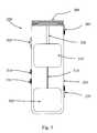
- FIG. 2is a view of an ophthalmic hand piece including a drug delivery tip segment and a limited reuse assembly according to an embodiment of the present invention.
- FIG. 3is a front view of a limited reuse assembly for an ophthalmic hand piece according to an embodiment of the present invention.
- FIG. 4is back view of a limited reuse assembly for an ophthalmic hand piece according to an embodiment of the present invention.
- FIG. 5is cross section view of a limited reuse assembly for an ophthalmic hand piece according to an embodiment of the present invention.
- FIG. 6is a block diagram of an ophthalmic hand piece including a drug delivery tip segment and a limited reuse assembly according to an embodiment of the present invention.
- FIG. 7is an exploded cross section view of a drug delivery tip segment for an ophthalmic hand piece according to an embodiment of the present invention.
- FIG. 8is cross section view of a drug delivery tip segment and a limited reuse assembly according to an embodiment of the present invention.
- FIG. 9is cross section view of a cauterizing tip segment and a limited reuse assembly according to an embodiment of the present invention.
- FIG. 10is cross section view of a drug delivery tip segment and a partial cross section view of a limited reuse assembly according to an embodiment of the present invention.
- FIG. 11is cross section view of a drug delivery tip segment and a partial cross section view of a limited reuse assembly according to an embodiment of the present invention.
- FIG. 12is cross section view of a drug delivery tip segment and a partial cross section view of a limited reuse assembly according to an embodiment of the present invention.
- FIG. 13is a block diagram of a method of operating a drug delivery hand piece according to an embodiment of the present invention.
- FIG. 14is a block diagram of a method of operating a drug delivery hand piece according to an embodiment of the present invention.
- FIGS. 15A & 15Bare a block diagram of a method of operating a drug delivery hand piece according to an embodiment of the present invention.
- FIG. 2depicts one view of an ophthalmic hand piece including a drug delivery tip segment and a limited reuse assembly according to an embodiment of the present invention.
- the hand pieceincludes a tip segment 205 and a limited reuse assembly 250 .
- the tip segment 205includes a needle 210 , a housing 215 , and a plunger connection 225 .
- the limited reuse assembly 250includes a housing 255 , a switch 270 , a lock mechanism 265 , and a threaded portion 260 .
- the tip segment 205is capable of being connected to and removed from the limited reuse assembly 250 .
- the tip segment 205has a threaded portion on an interior surface of housing 215 that screws onto the threaded portion 260 of limited reuse assembly 250 .
- lock mechanism 265secures tip segment 215 to limited reuse assembly 250 .
- Lock mechanism 265may be in the form of a button or a sliding switch.
- Needle 210is adapted to deliver a substance, such as a drug, into an eye.
- Switch 270is adapted to provide an input to the system.
- switch 270may be used to activate the system or to turn on a heater.
- FIG. 3is a front view of a limited reuse assembly for an ophthalmic hand piece according to an embodiment of the present invention.
- limited reuse assembly 250includes button 305 , indicators 310 , 315 , housing 255 , and threaded portion 260 .
- Button 305is located on housing 255 and provides an input to the system.
- button 305may be used to activate the system, the delivery of a drug, or other operation of the tip segment 205 .
- Indicators 310 , 315are located on housing 255 .
- indicators 310 , 315are light emitting diodes that indicate a status of the system.
- indicator 310may illuminate when the substance to be delivered into the eye has been heated to a proper temperature range.
- Indicator 315may illuminate when the substance has been delivered into the eye.
- a safety algorithmis implemented when the tip segment 205 is a drug delivery tip segment.
- the input devicesuch as button 305 , that actuates the delivery of the drug, is disabled until the drug reaches the proper temperature range. In this manner, the delivery of the drug only occurs after the drug has reached the proper temperature range.
- This safety algorithmcan be implemented when the drug is contained in a phase-transition lipid.
- the drugis contained in a substance that has a temperature-dependent viscosity. The substance and drug are heated so that the viscosity is suitable for delivery into an eye.
- FIG. 4is back view of a limited reuse assembly for an ophthalmic hand piece according to an embodiment of the present invention.
- the limited reuse assembly 250includes a housing 255 , a switch 270 , a lock mechanism 265 , and a threaded portion 260 .
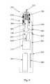
- FIG. 5is a cross section view of a limited reuse assembly for an ophthalmic hand piece according to an embodiment of the present invention.
- power source 505interface 510 , motor 515 , and motor shaft 520 are located in housing 255 .
- the top part of housing 255has a threaded portion 260 .
- Lock mechanism 265 , switch 270 , button 305 , and indicators 310 , 315are all located on housing 255 .
- Power source 505is typically a rechargeable battery, although other types of batteries may be employed. In addition, any other type of power cell is appropriate for power source 505 . Power source 505 provides power to the system, and more particularly to motor 515 . Power source 505 also provides power to a tip segment connected to limited reuse assembly 250 . In such a case, power source 505 may provide power to a heater (not shown) located in the tip segment. Power source 505 can be removed from housing 255 through a door or other similar feature (not shown).
- Interface 510is typically an electrical conductor that allows power to flow from power source 505 to motor 515 .
- Other interfaceslike interface 510 , may also be present to provide power to other parts of the system.
- Motor shaft 520is connected to and driven by motor 515 .
- Motor 515is typically a stepper motor or other type of motor that is capable of moving motor shaft 520 precise distances.
- motor shaft 520is connected via a mechanical linkage to a tip segment that delivers a drug into an eye.
- motor 515is a stepper motor that can precisely move shaft 520 to deliver a precise quantity of drug into the eye.
- Motor 515is secured to an interior surface of housing 255 by, for example, tabs that engage the outer surface of motor 515 .
- Lock mechanism 265 , switch 270 , and button 305are all located on housing 255 so that they can be manipulated by hand. Likewise, indicators 310 , 315 are located on housing 255 so that they can be viewed. Lock mechanism 265 , switch 270 , button 305 , and indicators 310 , 315 are also connected to a controller (not shown) via interfaces (not shown) located in housing 255 .
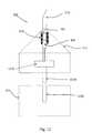
- FIG. 6is a block diagram of an ophthalmic hand piece including a drug delivery tip segment 205 and a limited reuse assembly 250 according to an embodiment of the present invention.
- the components contained in the tip segment 205are located above the dotted line while the components contained in the limited reuse assembly 250 are located below the dotted line.
- tip segment 205includes heater 610 and drug delivery device 615 .
- Limited reuse assembly 250includes power source 505 , motor 515 , controller 605 , switch 270 , button 305 , and interfaces 620 , 625 , 630 , and 650 .
- Electrical interface 630 , data interface 640 , and mechanical interface 645each form connections between tip segment 205 and limited reuse assembly 250 .
- controller 605is connected to switch 270 via interface 620 , to button 305 via interface 625 , to power source 505 via interface 650 , to motor 515 via interface 635 , and to heater 610 via electrical interface 630 .
- Data interface 640connects controller 605 to tip segment 205 .
- Motor 515is connected to drug delivery device 615 via mechanical interface 645 .
- power source 505is typically a rechargeable battery, although other types of batteries may be employed. In addition, any other type of power cell is appropriate for power source 505 .
- power source 505is a fuel cell, such as a methanol, water-based, or hydrogen fuel cell. In other embodiments, power source 505 is a lithium ion battery. Due to the compact nature of the hand piece, power source 505 is typically the size of one or two AA batteries. Such a size permits the application of many different battery and fuel cell technologies.
- Controller 605is typically an integrated circuit capable of performing logic functions. Controller 605 is typically in the form of a standard IC package with power, input, and output pins. In various embodiments, controller 605 is a motor controller, a heater controller, or a targeted device controller. In such a case, controller 605 performs specific control functions targeted to a specific device, such as a heater. For example, a heater controller has the basic functionality to control a heater, but may not have the functionality to control a motor. In other embodiments, controller 605 is a microprocessor. In such a case, controller 605 is programmable so that it can function to control different tip segments that perform different functions. In other cases, controller 605 is not a programmable microprocessor, but instead is a special purpose controller that is configured to control different tip segments that perform different functions.
- Controller 605also typically receives input data via data interface 640 and interfaces 620 , 625 .
- Data interface 640carries data from the tip segment to controller 605 .
- Such datamay include a status of the tip segment or a component thereof.
- data interface 640may carry information about the type of tip segment connected to the limited reuse assembly, the dosage of a drug that is to be delivered into an eye, the status of the heater, the status of the drug delivery device, or other similar information about the system.
- Interface 620carries a signal from switch 270 to controller 605 . This signal, for example, may activate the heater or activate the hand piece. Interface 625 carries a signal from button 305 to controller 605 . This signal, for example, may activate the tip segment and initiate the delivery of a drug into they eye.
- data interface 640 and interfaces 620 , 625 , 635 , 650may all share a common interface line. Alternatively, any combination of these interfaces may share a common line. In such a case, one or more interface lines may carry signals from one or more different components of the system. For example, switch 270 and button 306 may share a single interface line that carries signals from both of them. These interfaces are typically made of an electrical conductor such as wire.
- motor 515is typically a stepper motor, such as a variable reluctance motor, bipolar motor, unipolar motor, or bifilar motor. In other embodiments, motor 515 is any type of motor capable of moving its shaft finely or in small increments.
- Drug delivery device 615is driven by motor 515 via mechanical interface 645 .
- motor 515provides a force that is transferred to drug delivery device 615 via a mechanical interface 645 . Details of drug delivery device 615 are explained with reference to FIGS. 7-8 and 10 - 12 .
- Heater 610is typically a resistive type heater.
- heater 610is a continuous wire with a resistance through which a current is passed.
- heater 610contains resistive elements connected in series through which a current is passed. The amount of current passed through heater 610 and the resistive characteristics of heater 610 are selected to provide the proper amount of heat.
- Electrical connectionsprovide current to heater 610 . These connections typically provide current to heater 610 from power source 505 .
- a control line or electrical interface 630provides signals that control the operation of heater 610 .
- a controller 605receives temperature information from heater 610 and provides signals that control the operation of heater 610 .
- FIG. 7is an exploded cross section view of a drug delivery tip segment for an ophthalmic hand piece according to an embodiment of the present invention.
- the drug delivery tip segmentincludes a plunger limited reuse assembly 710 , plunger tip 715 , mechanical linkage interface 720 , dispensing chamber 705 , dispensing chamber housing 725 , needle 210 , heater 610 , housing 215 , support 735 , and optional luer 730 .
- mechanical linkage interfaceis located on one end of plunger limited reuse assembly 710 .
- Plunger tip 715is located on the other end of plunger limited reuse assembly 710 .
- Plunger limited reuse assembly 710 and plunger tip 715collectively form a plunger.
- mechanical linkage interface 720is located on one end of the plunger.
- Dispensing chamber 705is enclosed by dispensing chamber housing 725 and plunger tip 715 .
- Needle 210is fluidly coupled to dispensing chamber 705 . In this manner, a substance located in dispensing chamber 725 can be contacted by plunger tip 715 and pushed out of needle 210 . Needle 210 is secured to the drug delivery tip segment by optional luer 730 .
- Heater 610is located on dispensing chamber housing 725 and at least partially surrounds dispensing chamber 705 .
- Support 735holds the plunger (plunger limited reuse assembly 710 and plunger tip 715 ) and dispensing chamber housing 725 in place within housing 215 .
- Housing 215forms an outer skin on the drug delivery tip segment and at least partially encloses plunger limited reuse assembly 710 , plunger tip 715 , dispensing chamber 705 , and dispensing chamber housing 725 .
- a substance to be delivered into an eyeis located in dispensing chamber 705 .
- the substanceis contacted by the inner surface of dispensing chamber housing 725 and one face of plunger tip 715 .
- dispensing chamber 705is cylindrical in shape.
- Heater 610is in thermal contact with dispensing chamber housing 725 . In this manner, heater 610 is adapted to heat the contents of dispensing chamber 725 . Current is applied to heater 610 through an electrical interface (not shown).
- the substance located in dispensing chamber 705is a drug that is preloaded into the dispensing chamber.
- the drug delivery tip segmentis appropriate as a single use consumable product.
- Such a disposable productcan be assembled at a factory with a dosage of a drug installed. A precise volume of a substance can be preloaded into the delivery device. This helps to prevent dosing error on the part of the medical professional.
- the drugcan be stored under precise conditions. Shipment of a preloaded system can also be accomplished under precise conditions.
- a set quantity of the drugcan be preloaded. For example, 100 microliters of a drug can be loaded into dispensing chamber 705 , and any quantity up to 100 microliters can be dispensed.
- the plungerplunger limited reuse assembly 710 and plunger tip 715
- the plungercan be moved a precise distance to deliver a precise dosage of drug from the dispensing chamber 705 , through the needle 210 , and into an eye. This provides for flexibility of dosing and for ease of assembly.
- the drug delivery tip segment of FIG. 7is attached to a limited reuse assembly (not shown).
- Mechanical interface 720mates with a mechanical interface on the limited reuse assembly.
- plunger limited reuse assembly 710When a force is applied to plunger limited reuse assembly 710 , plunger tip 715 is displaced. The displacement of plunger tip 715 in turn displaces the substance contained in dispensing chamber 705 . The substance is pushed out of needle 210 .
- FIG. 8is cross section view of a drug delivery tip segment and a limited reuse assembly according to an embodiment of the present invention.
- FIG. 8shows how tip segment 205 interfaces with limited reuse assembly 250 .
- tip segment 205includes mechanical linkage interface 720 , plunger 805 , dispensing chambering housing 725 , tip segment housing 215 , heater 610 , needle 210 , dispensing chamber 705 , interface 830 , and tip interface connector 820 .
- Limited reuse assembly 250includes mechanical linkage 845 , motor shaft 810 , motor 515 , power source 505 , controller 840 , limited reuse assembly housing 255 , interface 835 , and limited reuse assembly interface connector 825 .
- mechanical linkage 720is located on one end of plunger 805 .
- the other end of plunger 805forms one end of dispensing chamber 705 .
- Plunger 805is adapted to move slidably within dispensing chamber 705 .
- An outer surface of plunger 805is fluidly sealed to an inner surface of dispensing chamber housing 725 .
- Dispensing chamber housing 725surrounds the dispensing chamber 705 .
- dispensing chamber housing 725has a cylindrical shape.
- dispensing chamber 705also has a cylindrical shape.
- Needle 210is fluidly coupled to dispending chamber 705 .
- a substance contained in dispending chamber 705can pass through needle 210 and into an eye.
- Heater 610at least partially surrounds dispensing chamber housing 725 .
- heater 610is adapted to heat dispensing chamber housing 725 and any substance contained in dispending chamber 705 .
- heater 610is in thermal contact with dispensing chamber housing 725 .
- Interface 830connects heater 610 with tip interface connector 820 .
- tip segment housing 215The components of tip segments of 205 , including dispensing chamber housing 725 , heater 610 , and plunger 805 are at least partially enclosed by tip segment housing 215 .
- a sealis present on a bottom surface of tip segment housing 215 .
- plunger 805is sealed to tip segment housing 215 .
- This sealprevents contamination of any substance contained in dispensing chamber 705 .
- a sealis desirable.
- This sealcan be located at any point on plunger 805 or on dispensing chamber housing 725 .
- tip segment housing 215maybe connected to dispensing chamber housing 725 to form an air tight or fluid tight seal.
- tip segment housing 215maybe sealed to plunger 805 near the end on which mechanical linkage interface 720 resides. In such a case, an air tight or fluid tight seal may be formed between a location on plunger 805 and tip segment housing 215 .
- tip segment 205may contain a plunger stop mechanism.
- the bottom portion of plunger 805(the portion on which mechanical linkage interface 720 resides) is adapted to contact the bottom portion of dispensing chamber housing 725 .
- mechanical linkage interface 720also advances upward toward needle 210 .
- a top surface of mechanical linkage interface 720contacts a bottom surface of dispensing chamber housing 725 .
- the protrusions on the bottom end on plunger 805 and the bottom surface of dispensing chamber housing 725form a plunger stop mechanism.
- Plunger 805can not be advanced any further than the point at which the top surface of mechanical linkage interface 720 contacts the bottom surface of dispensing chamber housing 805 .
- a plunger stop mechanismcan provide a safety feature, such as to prevent plunger 805 from contacting needle 210 and possibly dislodging it.
- such a plunger stop mechanismmay also include a locking mechanism so that plunger 805 cannot be retracted or moved away from needle 210 when needle 210 is removed from the eye.
- Such a plunger lock mechanismhelps to prevent reflux of the substance when needle 210 is removed.
- power source 505provides power to motor 515 .
- An interface (not shown) between power source 505 and motor 515serves as a conduit for providing power to motor 515 .
- Motor 515is connected to motor shaft 810 .
- motor shaft 810is integral with motor 515 .
- Mechanical linkage interface 845is connected to motor shaft 810 . In this configuration, as motor 515 moves motor shaft 810 upward toward needle 210 mechanical linkage 845 also moves upward toward needle 210 .
- Controller 840is connected via interface 835 to limited reuse assembly interface connector 825 .
- Limited reuse assembly interface connector 825is located on a top surface of limited reuse assembly housing 255 adjacent to mechanical linkage interface 845 . In this manner, both limited reuse assembly interface connector 825 and mechanical linkage interface 845 are adapted to be connected with tip interface connector 820 and mechanical linkage interface 720 respectively.
- Controller 840 and motor 515are connected by an interface (not shown). This interface (not shown) allows controller 840 to control the operation of motor 515 .
- an optional interface (not shown) between power source 505 and controller 840allows controller 840 to control operation of power source of 505 . In such a case, controller 840 may control the charging and the discharging of power source 505 when power source 505 is a rechargeable battery.
- Tip segment 205is adapted to mate with or attach to limited reuse assembly 250 .
- mechanical linkage interface 720 located on a bottom surface of plunger 805is adapted to connect with mechanical linkage interface 845 located near a top surface of limited reuse assembly housing 255 .
- tip interface connector 820is adapted to connect with limited reuse assembly interface connector 825 .
- motor 515 and motor shaft 810are adapted to drive plunger 805 upward toward needle 210 .
- an interfaceis formed between controller 840 and heater 610 .
- a signalcan pass from controller 840 to heater 610 through interface 835 , limited reuse assembly interface connector 825 , tip interface connector 820 , and interface 830 .
- a signalcan pass from heater 610 to controller 840 through interface 830 , tip interface connector 820 , limited reuse assembly interface connector 825 , and interface 835 .
- controller 840is adapted to control the operation of heater 610 .
- controller 840controls the operation of motor 515 .
- Motor 515is actuated and motor shaft 810 is moved upward toward needle 210 .
- mechanical linkage interface 845which is connected to mechanical linkage interface 720 , moves plunger 805 upward toward needle 210 .
- a substance located in dispensing chamber 705is then expelled through needle 210 .
- controller 840controls the operation of heater 610 .
- Heater 610is adapted to heat an outside surface of dispensing chamber housing 725 . Since dispensing chamber housing 725 is at least partially thermally conductive, heating dispensing chamber housing 725 heats a substance located in dispensing chamber 705 . Temperature information can be transferred from heater 610 through interface 830 , tip interface connector 820 , limited reuse assembly interface connector 825 , and interface 835 back to controller 840 . This temperature information can be used to control the operation of heater 610 . Typically, controller 840 controls the amount of current that is sent to heater 610 . The more current sent to heater 610 , the hotter it gets.
- controller 840can use a feed back loop comprising information about the temperature of heater 610 to control the operation of heater 610 .
- Any suitable type of control algorithmsuch as a proportional integral derivative algorithm, can be used to control the operation of heater 610 .
- FIG. 9is a cross section view of a cauterizing tip segment and a limited reuse assembly according to an embodiment of the present invention.
- limited reuse assembly 250is substantially the same as the limited reuse assembly 250 shown in FIG. 8 .
- Tip segment 200is a cauterizing tip rather than a drug delivery tip.
- Tip segment 205includes cauterizing driver 905 , tip segment housing 215 , cauterizing tip 910 , interface 830 , and tip interface connector 820 .
- Cauterizing driver 905is connected to cauterizing tip 910 and is adapted to operate cauterizing tip 910 .
- Cauterizing driver 905is connected to interface 830 which in turn is connected to tip interface connector 820 .
- Cauterizing tip segment 900is adapted to interface with and connect to limited reuse assembly 250 .
- cauterizing tip segment 900 and limited reuse assembly 250can be screwed together via two threaded segments (not shown).
- Tip interface connector 820is also adapted to interface with and connect to limited reuse assembly connector interface 825 .
- controller 840When cauterizing tip segment 900 is connected to limited reuse assembly 250 , controller 840 is connected to cauterizing driver 905 via interface 835 , limited reuse assembly interface connector 825 , tip interface connector 820 and interface 830 . In such a case, controller 840 can controller the operation of cauterizing driver 905 . For example, controller 840 can control the temperature at which cauterizing tip 910 is maintained by cauterizing driver 905 . In addition, signals passing between controller 840 and cauterizing driver 905 can serve to provide controller 840 with feedback information about the temperature of cauterizing tip 910 .
- cauterizing driver 905 and cauterizing tip 910are heating devices designed to cauterize blood vessels.
- Cauterizing tip 910is usually a small diameter wire. Such a small diameter wire can be easily inserted into the eye during surgery to cauterize blood vessels.
- limited reuse assembly 250is a universal limited reuse assembly.
- limited reuse assembly 250can be connected to at least two different types of tip segments, such as tip segment 205 and cauterizing tip segment 900 .
- Limited reuse assembly 250can operate either a drug delivery tip segment or a cauterizing tip segment.
- limited reuse assembly 250may be able to operate other types of tip segments that perform different functions.
- Such a universal limited reuse assemblyprovides streamlined operation as only one limited reuse assembly is required to operate multiple different tip segments.
- a single limited reuse assembly 250maybe manufactured and bundled with different tip segments.
- FIG. 10is a cross section view of a drug delivery tip segment and a partial cross section view of a limited reuse assembly according to an embodiment of the present invention.
- tip segment 205includes mechanical linkage interface 720 , plunger 805 , dispensing chamber housing 725 , tip segment housing 215 , heater 610 , needle 210 , dispensing chamber 705 , interface 830 , data store 1010 , and tip interface connector 820 .
- the embodiment of tip segment 205 shown in FIG. 10is similar to the embodiment of tip segment 205 shown in FIG. 8 with the exception that tip segment 205 of FIG. 10 includes a data store 1010 .
- Tip segment 205 of FIG. 10operates in the same manner as tip segment 205 of FIG. 8 .
- Limited reuse assembly interface connector 825 , interface 835 , mechanical linkage interface 845 , and motor shaft 810are shown in the partial rendering of the limited reuse assembly. These components operate in the same manner as described with reference to limited reuse assembly 250 in FIG. 8 .
- Data store 1010is connected to interface 830 in tip segment 205 .
- Data store 1010is typically a semiconductor memory such as an EEPROM.
- Data store 1010is configured to store identifying information about tip segment 205 .
- data store 1010may also store dosage information for a drug contained in dispensing chamber 705 .
- interface 830 , tip interface connector 820 , limited reuse assembly interface 825 , and interface 835all form a data interface between tip segment 205 and limited reuse assembly 250 .
- information from heater 610maybe passed back to limited reuse assembly 250 via this series of interfaces and interface connectors.
- data stored on data store 1010may also be read by controller (not shown) via this series of interfaces and interface connectors.
- controllernot shown
- tip segment 205is connected to limited reuse assembly 250
- mechanical linkage interface 845is connected to mechanical linkage interface 720 and tip interface connector 820 is connected to limited reuse assembly interface connector 825 .
- the connection of tip interface connector 820 to limited reuse assembly interface connector 825allows the transfer of information or data from heater 610 and data store 1010 to controller 840 .
- information about a type of tip segmentis stored on data store 1010 .
- This informationrelates to whether tip segment 205 is a drug delivery tip segment, a cauterizing tip segment, or any other type of tip segment.
- This identifier information stored on data store 1010can be read by controller 840 .
- controller 840uses this information to determine the proper operation of tip segment 205 . For example, if tip segment 205 is a drug delivery tip segment or a drug delivery device, then controller 840 can use the proper algorithm to control tip segment 205 .
- a cauterizing tip segmentsuch as cauterizing tip segment 900
- information stored on data 1010can be used by controller 840 to control the operation of the cauterizing tip.
- data store 1010may also contain dosage information.
- tip segment 205is a drug delivery tip segment
- information about a proper drug dosage for a drug contained in dispensing chamber 705maybe contained on data store 1010 .
- controller 840can read the dosage information from data store 1010 and operate motor 515 in a manner suitable to deliver the proper dosage.
- 100 microlitersmay be contained dispensing chamber 705 .
- Information stating that a dosage of 20 microliters is to be delivered into an eyemaybe stored on data store 1010 .
- controller 840reads the dosage information (that 20 microliters should be delivered into the eye) from data store 1010 .
- Controller 840can then operate motor 515 to deliver the 20 microliter dosage.
- Controller 840can cause motor 515 to move motor shaft 810 and mechanical linkage 845 a set distance related to a dosage of 20 microliters. In such a case, plunger 805 is moved this set distance so that only 20 micro liters of a drug is expelled from needle 210 and into an eye.
- controller 840has various plunger distances stored on it. Each of these plunger distances is related to a different dosage. For example, one plunger distance maybe associated with a dosage of 20 microliters and a second larger plunger distance maybe associated with a dosage of 40 microliters. In this manner controller 840 can use the set plunger distance to control motor 515 , motor shaft 810 , mechanical linkage interface 845 , and mechanical linkage interface 720 to move plunger 805 this set distance. In other words, controller 840 uses a distance that plunger 805 must travel to deliver a given dosage of drug.
- motor shaft 810 and mechanical linkage interface 845are connected to mechanical linkage interface 720 , a movement of motor shaft 810 produces a corresponding movement of plunger 805 .
- controller 840controls the movement of motor 515 such that plunger 805 is moved the proper distance to deliver the required dosage from dispensing chamber 705 , through needle 210 , and into an eye.
- controller 840may calculate a distance that plunger 805 must be moved to deliver the desired dosage. For example, if dosage information corresponding to a drug dosage of 20 microliters is read from data store 1010 by controller 840 , then controller 840 may use this information to calculate a proper distance that plunger 805 must be moved. Since the volume of dispensing chamber 705 as well as the volume of a drug loaded in dispensing chamber 705 is known, a distance that plunger 805 must be moved to deliver that required dosage can be calculated by controller 840 .
- the volume of the dispensing chambercan be calculated by using the cross section area of the cylinder (the area of a circle) times the height of the dispensing chamber. This simple mathematical formula can be used to calculate the total volume of the dispensing chamber 705 . Since the cross section area of dispensing chamber 705 is constant for any given application, the height which corresponds to a distance that plunger 805 travels can be calculated for any dosage amount.
- dispensing chamber 705For example, assume that 100 microliters of a drug is loaded into dispensing chamber 705 and that the cross section area of dispensing chamber 705 is 10. When dispensing chamber 705 is in the shape of a cylinder, the height of that cylinder is also 10. To deliver a dosage of 20 microliters which corresponds to 20% of the total volume of dispensing chamber 705 , it is necessary to move plunger 805 upward toward needle 210 a distance of 2. In other words, a dosage of 20 microliters corresponds to 20% of the total volume of dispensing chamber 705 . In such a case, plunger 805 should be moved upward toward needle 210 a distance equal to 20% of the total height of dispensing chamber 705 . Controller 840 can then control motor 515 such that motor shaft 810 moves drives plunger 805 upward a distance of 20% of the total height of dispensing chamber 705 .
- controller 840may read information about a rate at which plunger 805 should be moved in order to properly deliver a dosage of drug. In such a case, controller 840 reads information about the rate of drug delivery from data store 1010 and uses that information to operate motor 515 to drive plunger 805 at that rate.
- the rate at which plunger 805 movesmay be fixed or variable. In some applications, it may be desirable to move plunger 805 faster than in other applications. For example, when the drug contained in dispensing 705 is a drug that should be heated before being injected into an eye, it maybe desirable to drive plunger 805 at a rate such that the heated drug does not cool and clog needle 210 . In other applications, it maybe desirable to move plunger 805 slowly in order to improve the delivery of a drug contained in dispensing chamber 705 .
- data store 1010may also include any other type of information related to delivery of a drug.
- data store 1010may include information about the type of drug contained in dispensing chamber 705 , various characteristics of that drug, or other characteristics of a proper dosage or a proper delivery of that drug.
- data store 1010may contain safety information, information about the proper operation of tip segment 205 , or any other information related to the tip segment or limited reuse assembly.
- a dosagemaybe selectable by the medical professional who is administering the drug.
- an input device(not shown) located on limited reuse assembly 250 or on tip segment 205 may enable a doctor to select the desired drug dosage.
- controller 840receives the desired drug dosage and operates motor 515 to move plunger 805 the required distance to deliver the desired dosage.
- Such a user selectable dosage schememay be implemented simply by adding an extra input device.
- a number of different drug delivery tip segments 205maybe manufactured and loaded with a drug at the factory. Dosage information can also be loaded onto data store 1010 at the factory. In such a case, a number of different tip segments each with the same amount of drug contained in the dispensing chamber 705 but with different dosage information stored on data store 1010 can be manufactured and shipped. A doctor can then order the tip segment 205 with the required dosage information on the data store 1010 . Packaging can be clearly labeled to identify the dosage information so that the proper dosage is administered to a patient.
- FIG. 11is a cross section view of a drug delivery tip segment and a partial cross section view of a limited reuse assembly according to an embodiment of the present invention.
- tip segment 205includes a radio frequency identification tag 1110 .
- tip segment 205 of FIG. 11is identical to tip segment 205 of FIG. 8 .
- the various components and the operation of the various components of tip segment 205 of FIG. 8are the same as tip segment 205 of FIG. 11 .
- limited reuse assembly 250 depicted in FIG. 11also includes a radio frequency identification (FRID) reader 1120 and RFID interface 1130 .
- RFID interface 1130is connected to controller 840 (not shown).
- RFID tag 1110is configured to hold the same type of information that data store 1010 holds with respect to FIG. 10 . In this manner, RFID tag 1110 is simply another type of data store 1010 . However, as is commonly know, RFID tag 1110 does not require a wired connection to RFID reader 1120 . In this manner, a wireless connection between RFID tag 1110 and RFID reader 1120 can be established.
- the RFID reader 1130 of an RFID system(which includes RFID tag 1110 , RFID reader 1120 , and RFID interface 1130 ) is contained near the top of limited reuse assembly 250 .
- RFID reader 1120is located adjacent to mechanical linkage interface 845 near a top surface of limited reuse assembly housing 255 .
- RFID reader 1120is designed to read information from RFID tag 1110 .
- RFID tag 1110does not have a power supply. Instead, the passive RFID tag relies on the electromagnetic field produced by the RFID reader 1120 for its power. The electromagnetic field produced by the RFID reader 1120 and emitted from the RFID reader antenna (not shown) induces a small electrical current in RFID tag 1110 . This small electrical current allows RFID tag 1110 to operate. In this passive system the RFID tag is designed to collect power from both the electromagnetic field produced by the RFID reader 1120 and emitted by the RFID reader 1120 and to transmit an outbound signal that is received by the RFID reader 1120 .
- the RFID reader antenna(not shown) transmits a signal produced by the RFID reader 1120 .
- the RFID tag antenna(not shown) receives this signal and a small current is induced in the RFID tag 1110 . This small current powers the RFID tag 1110 .
- RFID tag 1110can then transmit a signal through its RFID tag antenna to RFID reader antenna and the RFID reader 1120 itself. In this manner, the RFID tag 1110 and the RFID read 1120 can communicate with each over a radio frequency link.
- RFID tag 1110transmits information, such as dosage information or tip segment information, through RFID tag antenna to RFID reader 1120 . This information is received by RFID reader 1120 . In this manner, information can be transferred from the tip segment 205 to the limited reuse assembly 250 .
- the RFID reader 1120can transmit information to the RFID tag 1110 in a similar fashion.
- RFID reader 1120can transmit information such as dosage information over the radio frequency signal emitted by RFID reader 1120 .
- RFID tag 1120receives this radio frequency signal with the information.
- RFID tag 1110can then store this information.
- any other type of wireless systemcan be used to transfer information between limited reuse assembly 250 and tip segment 205 .
- a Bluetooth protocolmaybe used to establish a communication link between limited reuse assembly 250 and tip segment 205 .
- Informationcan then be transferred between limited reuse assembly 250 and tip segment 205 over this communication link.
- Other embodiments used to transfer informationinclude an infrared protocol, 802.11, fire wire, or other wireless protocol.
- tip segment 205 of FIG. 11is similar to the operation of tip segment 205 of FIG. 10 .
- the difference between the embodiment of FIG. 10 and the embodiment of FIG. 11is that the embodiment of FIG. 11 uses an RFID system rather than a wired data store system to transfer information to tip segment 205 to limited reuse assembly 250 .
- interface 830 , tip interface connector 820 , limited reuse assembly interface connector 825 , and interface 835form an electrical interface.
- this series of interfaces and interface connectorscarries power to heater 610 .
- this series of interface and interface connectorscan operate both as a data interface and a power interface.
- FIG. 12is a cross section view of a drug delivery tip segment and a partial cross section view of a limited reuse assembly according to an embodiment of the present invention.
- tip segment 205includes motor 1210 , heater 610 , needle 210 , substance 1215 , plunger 805 , tip segment housing 215 , and shaft 1220 .
- Limited reuse assembly 250includes limited reuse assembly housing 255 and shaft hold 1230 .
- motor 1210is contained in tip segment 205 and not in limited reuse assembly 250 .
- Shaft 1220is connected to motor 1210 .
- Motor 1210is connected to plunger 805 .
- Substance 1215is located within needle 210 above the upper surface of plunger 805 .
- Heater 610surrounds needle 210 in the vicinity of substance 215 .
- Motor 1210 , plunger 805 , and heater 610are all at least partially enclosed in tip segment housing 215 .
- Shaft hold 1230is included in limited reuse assembly housing 255 .
- Shaft hold 1230operates to interface with shaft 1220 when tip segment 205 and limited reuse assembly 250 are connected together.
- tip segment 205is connected to limited reuse assembly 250 .
- Shaft 1220is inserted into shaft hold 1230 and tip segment 205 is fastened to limited reuse assembly 250 .
- tip segment housing 215is attached to limited reuse assembly housing to 255 .
- a controller(not shown) contained within limited reuse assembly housing 255 operates motor 1210 contained within tip segment housing 215 .
- the operation of the drug delivery tip segment 205 of FIG. 12is similar to that described with respect to the drug delivery tip segment 205 of FIG. 8 .
- motor 1210is contained within tip segment 205 .
- tip segment 205When tip segment 205 is disposable, motor 1210 must also be discarded along with tip segment 205 .
- Motor 1210 contained in tip segment housing 215may also allow for a better seal so that substance 1215 contained in needle 210 is not contaminated.
- FIG. 13is a block diagram of a method of operating a drug delivery hand piece according to an embodiment of the present invention.
- a first inputis received.
- this first inputis generated via a switch or button located on the hand piece.
- a switch or buttonlocated on the hand piece.
- a surgeonmay activate a switch to turn the heater on.
- a heateris activated to heat a substance contained in a dispensing chamber.
- currentis provided to the heater and controlled by the controller.
- dosage informationis received.
- This dosage informationis typically received by the controller so that the controller can control the operation of the hand piece to deliver the required dosage.
- the dosage informationmay be located in the tip segment itself (on a memory or RFID tag as previously described). In such a case, the dosage information is transferred from the tip segment to the limited reuse assembly.
- a second inputis received.
- this second inputis generated via a switch or button located on the hand piece.
- a surgeonmay press a button to begin the delivery of the substance.
- a plungeris moved in the tip segment to deliver the proper dosage of the substance.
- the second inputstarts the drug delivery process.
- the controlleruses this second input and the dosage information to control the operation of the motor and attached plunger.
- the controloperates the motor to move the plunger a distance that delivers the specified dosage.
- the controllermay also use the dosage information to control the rate at which the motor moves the plunger.
- an indication that the substance has been deliveredis provided.
- This indicationcan be in the form of an illuminated LED.
- an indication that the substance has reached the proper temperature rangecan be provided by illuminating an LED as well.
- the controllermay also ensure that the substance has reached the proper temperature before the substance is delivered. In such a case, the controller does not allow the second input to commence the delivery process until the substance has reached the proper temperature range.
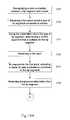
- FIG. 14is a block diagram of a method of operating a drug delivery hand piece according to an embodiment of the present invention.
- a connection between a tip segment and a limited reuse assemblyis recognized.
- a medical professionalattaches the tip segment to the limited reuse assembly by, for example, screwing the tip segment onto the limited reuse assembly.
- This connectionis recognized by an electrical or RF connection between the tip segment and the limited reuse assembly.
- the connectionis recognized by the limited reuse assembly when the RFID reader in the limited reuse assembly reads information from the RFID tag in the tip segment.
- an electrical or data interfaceconnects the tip segment to the limited reuse assembly to allow information to be read from the tip segment by the controller in the limited reuse assembly.
- the type of tip segmentis determined by the limited reuse assembly.
- the controllerreceives information about the type of tip segment. This information is typically stored in or on the tip segment itself.
- the controllerreceives information about the type of tip segment. The controller can use the information about the type of tip segment to select an algorithm to control the tip segment.
- the limited reuse assemblyalso receives dosage information. This dosage information is received by the controller in a similar fashion.
- a first inputis received.
- this first inputis generated via a switch or button located on the hand piece.
- a switch or buttonlocated on the hand piece.
- a surgeonmay activate a switch to turn the heater on.
- a heateris activated to heat a drug contained in a dispensing chamber.
- currentis provided to the heater and controlled by the controller.
- the dosage informationis used to control the rate of movement and distance the plunger travels.
- a second inputis received.
- this second inputis generated via a switch or button located on the hand piece. For example, a surgeon may press a button to begin the delivery of the substance.
- the second inputis only accepted by the hand piece after the drug has reached the proper temperature range. In this manner, the initiation of the drug delivery is only enabled after the drug has reached the proper temperature range. This prevents the administration of the drug when it is not in the proper temperature range. As noted above, delivering the drug only when it is in the proper temperature range may be necessary for efficacy.
- the motoris activated to move the plunger the tip segment to deliver the proper dosage of the drug.
- the second inputstarts the drug delivery process.
- the controlleruses this second input and the dosage information to control the operation of the motor and attached plunger.
- the controloperates the motor to move the plunger a distance that delivers the specified dosage.
- the controllermay also use the dosage information to control the rate at which the motor moves the plunger.
- the drugis delivered into the eye from the tip segment.
- an indication that the substance has been deliveredcan be provided.
- This indicationcan be in the form of an illuminated LED.
- an indication that the substance has reached the proper temperature rangecan be provided by illuminating an LED as well.
- FIGS. 15A & 15Bare a block diagram of a method of operating a drug delivery hand piece according to an embodiment of the present invention.
- a data connectionis recognized between the tip segment and the limited reuse assembly.
- This data connectioncan be a wireless connection like an RFID connection, or it can be a wired connection like a data interface.
- the limited reuse assemblyreceives information about the type of tip segment connected to it.
- the limited reuse assemblyuses the information about the type of tip segment, selects a suitable control algorithm. The controller may select one of several control algorithms stored in memory.
- a first inputis received.
- the heateris activated to heat the substance contained in the tip segment.
- the controllerreceives temperature information from the tip segment.
- the controllercontrols the operation of the heater using the temperature information. In such a case, the controller is configured to regulate the heater. The controller may control the amount of current to the heater to control the temperature of the substance.
- the controllerreceives dosage information.
- the controlleruses the dosage information, determines a distance that the plunger in the tip segment must be moved to deliver the proper dosage.
- a first indication that the temperature of the substance has reached the proper temperature rangeis provided.
- a second inputis received.
- the motoris activated to move the plunger the distance to deliver the proper dosage.
- a second indication that the substance has been deliveredis provided.
- the present inventionprovides an improved system and methods for delivering precise volumes of a substance into an eye.
- the present inventionprovides a single use, disposable delivery device tip segment that is capable of delivering a precise dosage without reflux.
- the tip segmentinterfaces with a universal hand piece limited reuse assembly capable of operating different types of tip segments.
- the substance that is to be delivered into the eyetypically a drug, is maintained in a temperature range by the temperature control features of the present invention.
- the present inventionis illustrated herein by example, and various modifications may be made by a person of ordinary skill in the art.
Landscapes
- Health & Medical Sciences (AREA)
- General Health & Medical Sciences (AREA)
- Public Health (AREA)
- Biomedical Technology (AREA)
- Heart & Thoracic Surgery (AREA)
- Animal Behavior & Ethology (AREA)
- Life Sciences & Earth Sciences (AREA)
- Engineering & Computer Science (AREA)
- Veterinary Medicine (AREA)
- Vascular Medicine (AREA)
- Anesthesiology (AREA)
- Hematology (AREA)
- Ophthalmology & Optometry (AREA)
- Nuclear Medicine, Radiotherapy & Molecular Imaging (AREA)
- Surgery (AREA)
- Infusion, Injection, And Reservoir Apparatuses (AREA)
- Prostheses (AREA)
Abstract
Description
Claims (46)
Priority Applications (1)
| Application Number | Priority Date | Filing Date | Title |
|---|---|---|---|
| US12/443,898US8118790B2 (en) | 2006-05-17 | 2007-10-09 | Battery operated surgical hand piece with disposable end |
Applications Claiming Priority (6)
| Application Number | Priority Date | Filing Date | Title |
|---|---|---|---|
| US11/435,906US20070270750A1 (en) | 2006-05-17 | 2006-05-17 | Drug delivery device |
| US92149806P | 2006-10-16 | 2006-10-16 | |
| US92149706P | 2006-10-16 | 2006-10-16 | |
| US92149906P | 2006-10-16 | 2006-10-16 | |
| PCT/US2007/080751WO2008105957A2 (en) | 2006-10-16 | 2007-10-09 | Battery operated ophthalmic hand piece with disposable end |
| US12/443,898US8118790B2 (en) | 2006-05-17 | 2007-10-09 | Battery operated surgical hand piece with disposable end |
Related Parent Applications (1)
| Application Number | Title | Priority Date | Filing Date |
|---|---|---|---|
| US11/435,906Continuation-In-PartUS20070270750A1 (en) | 2006-05-17 | 2006-05-17 | Drug delivery device |
Publications (2)
| Publication Number | Publication Date |
|---|---|
| US20100211044A1 US20100211044A1 (en) | 2010-08-19 |
| US8118790B2true US8118790B2 (en) | 2012-02-21 |
Family
ID=39721776
Family Applications (2)
| Application Number | Title | Priority Date | Filing Date |
|---|---|---|---|
| US11/688,573ActiveUS7811252B2 (en) | 2006-05-17 | 2007-03-20 | Dosage control device |
| US12/443,898Expired - Fee RelatedUS8118790B2 (en) | 2006-05-17 | 2007-10-09 | Battery operated surgical hand piece with disposable end |
Family Applications Before (1)
| Application Number | Title | Priority Date | Filing Date |
|---|---|---|---|
| US11/688,573ActiveUS7811252B2 (en) | 2006-05-17 | 2007-03-20 | Dosage control device |
Country Status (14)
| Country | Link |
|---|---|
| US (2) | US7811252B2 (en) |
| EP (2) | EP2077809A2 (en) |
| JP (2) | JP5155326B2 (en) |
| KR (1) | KR20090091133A (en) |
| CN (3) | CN101534758A (en) |
| AR (9) | AR063297A1 (en) |
| AU (2) | AU2007348948A1 (en) |
| BR (1) | BRPI0717303B8 (en) |
| CA (2) | CA2664635A1 (en) |
| ES (1) | ES2614646T3 (en) |
| MX (1) | MX2009003395A (en) |
| RU (1) | RU2009118434A (en) |
| TW (2) | TW200826986A (en) |
| WO (2) | WO2008112011A2 (en) |
Cited By (7)
| Publication number | Priority date | Publication date | Assignee | Title |
|---|---|---|---|---|
| US9283334B2 (en) | 2011-11-23 | 2016-03-15 | Northgate Technologies Inc. | System for identifying the presence and correctness of a medical device accessory |
| US10485630B2 (en) | 2015-12-16 | 2019-11-26 | Novartis Ag | Systems and methods for a hand-controllable surgical illumination device |
| US10537401B2 (en) | 2016-11-21 | 2020-01-21 | Novartis Ag | Vitreous visualization system and method |
| US10758683B2 (en) | 2013-10-24 | 2020-09-01 | Amgen Inc. | Drug delivery system with temperature-sensitive control |
| US10939815B2 (en) | 2016-11-21 | 2021-03-09 | Alcon Inc. | Systems and methods using a vitreous visualization tool |
| US11801343B2 (en) | 2018-07-12 | 2023-10-31 | Alcon Inc. | Methods and systems for delivering material to a body part |
| USD1037439S1 (en) | 2022-01-17 | 2024-07-30 | EyePoint Pharamaceuticals, Inc. | Ocular injector |
Families Citing this family (47)
| Publication number | Priority date | Publication date | Assignee | Title |
|---|---|---|---|---|
| US7431710B2 (en) | 2002-04-08 | 2008-10-07 | Glaukos Corporation | Ocular implants with anchors and methods thereof |
| DE10224750A1 (en) | 2002-06-04 | 2003-12-24 | Fresenius Medical Care De Gmbh | Device for the treatment of a medical fluid |
| US8197231B2 (en) | 2005-07-13 | 2012-06-12 | Purity Solutions Llc | Diaphragm pump and related methods |
| US7981095B2 (en) | 2005-07-18 | 2011-07-19 | Tearscience, Inc. | Methods for treating meibomian gland dysfunction employing fluid jet |
| US8950405B2 (en)* | 2006-05-15 | 2015-02-10 | Tearscience, Inc. | Treatment of obstructive disorders of the eye or eyelid |
| US20090043365A1 (en) | 2005-07-18 | 2009-02-12 | Kolis Scientific, Inc. | Methods, apparatuses, and systems for reducing intraocular pressure as a means of preventing or treating open-angle glaucoma |
| WO2013003594A2 (en) | 2011-06-28 | 2013-01-03 | Tearscience, Inc. | Methods and systems for treating meibomian gland dysfunction using radio-frequency energy |
| US7981145B2 (en) | 2005-07-18 | 2011-07-19 | Tearscience Inc. | Treatment of meibomian glands |
| US20070060988A1 (en) | 2005-07-18 | 2007-03-15 | Grenon Stephen M | Melting meibomian gland obstructions |
| US20070016256A1 (en) | 2005-07-18 | 2007-01-18 | Korb Donald R | Method and apparatus for treating gland dysfunction |
| US20080114423A1 (en) | 2006-05-15 | 2008-05-15 | Grenon Stephen M | Apparatus for inner eyelid treatment of meibomian gland dysfunction |
| US8128673B2 (en) | 2006-05-15 | 2012-03-06 | Tearscience, Inc. | System for inner eyelid heat and pressure treatment for treating meibomian gland dysfunction |
| US8128674B2 (en) | 2006-05-15 | 2012-03-06 | Tearscience, Inc. | System for outer eyelid heat and pressure treatment for treating meibomian gland dysfunction |
| US8137390B2 (en) | 2006-05-15 | 2012-03-20 | Tearscience, Inc. | System for providing heat treatment and heat loss reduction for treating meibomian gland dysfunction |
| US9314369B2 (en)* | 2006-05-15 | 2016-04-19 | Tearscience, Inc. | System for inner eyelid treatment of meibomian gland dysfunction |
| US20080281292A1 (en)* | 2006-10-16 | 2008-11-13 | Hickingbotham Dyson W | Retractable Injection Port |
| WO2009086112A2 (en)* | 2007-12-20 | 2009-07-09 | University Of Southern California | Apparatus and methods for delivering therapeutic agents |
| US8192401B2 (en) | 2009-03-20 | 2012-06-05 | Fresenius Medical Care Holdings, Inc. | Medical fluid pump systems and related components and methods |
| US8372036B2 (en) | 2009-05-06 | 2013-02-12 | Alcon Research, Ltd. | Multi-layer heat assembly for a drug delivery device |
| WO2010135369A1 (en) | 2009-05-18 | 2010-11-25 | Dose Medical Corporation | Drug eluting ocular implant |
| US10206813B2 (en) | 2009-05-18 | 2019-02-19 | Dose Medical Corporation | Implants with controlled drug delivery features and methods of using same |
| WO2012071476A2 (en) | 2010-11-24 | 2012-05-31 | David Haffner | Drug eluting ocular implant |
| US8777897B2 (en)* | 2009-07-06 | 2014-07-15 | Carefusion 303, Inc. | Fluid delivery systems and methods having wireless communication |
| WO2011008858A1 (en) | 2009-07-15 | 2011-01-20 | Fresenius Medical Care Holdings, Inc. | Medical fluid cassettes and related systems and methods |
| US20110112466A1 (en)* | 2009-11-11 | 2011-05-12 | Ramon Carsola Dimalanta | Extended Point Phacoemulsification Tip |
| US8177747B2 (en) | 2009-12-22 | 2012-05-15 | Alcon Research, Ltd. | Method and apparatus for drug delivery |
| US8864703B2 (en) | 2010-10-05 | 2014-10-21 | Alcon Research, Ltd. | Drug introduction and placement system |
| US9624915B2 (en) | 2011-03-09 | 2017-04-18 | Fresenius Medical Care Holdings, Inc. | Medical fluid delivery sets and related systems and methods |
| MX341315B (en) | 2011-04-21 | 2016-08-12 | Fresenius Medical Care Holdings Inc | Medical fluid pumping systems and related devices and methods. |
| US10245178B1 (en) | 2011-06-07 | 2019-04-02 | Glaukos Corporation | Anterior chamber drug-eluting ocular implant |
| EP2656865A1 (en)* | 2012-04-24 | 2013-10-30 | Sanofi-Aventis Deutschland GmbH | Syringe carrier with needle shield and data storage device for use in a medical auto-injection device |
| US9610392B2 (en) | 2012-06-08 | 2017-04-04 | Fresenius Medical Care Holdings, Inc. | Medical fluid cassettes and related systems and methods |
| US9500188B2 (en)* | 2012-06-11 | 2016-11-22 | Fresenius Medical Care Holdings, Inc. | Medical fluid cassettes and related systems and methods |
| US10842670B2 (en) | 2012-08-22 | 2020-11-24 | Johnson & Johnson Vision Care, Inc. | Apparatuses and methods for diagnosing and/or treating lipid transport deficiency in ocular tear films, and related components and devices |
| USD705924S1 (en)* | 2012-11-02 | 2014-05-27 | Corinthian Ophthalmic, Inc. | Droplet ejection device |
| US9561323B2 (en) | 2013-03-14 | 2017-02-07 | Fresenius Medical Care Holdings, Inc. | Medical fluid cassette leak detection methods and devices |
| EP3744391B1 (en) | 2013-04-30 | 2023-03-01 | Alcon Inc. | Systems for the treatment of eye conditions |
| US9763827B2 (en) | 2013-04-30 | 2017-09-19 | Tear Film Innovations, Inc. | Systems and methods for the treatment of eye conditions |
| EP3677229A1 (en) | 2014-05-29 | 2020-07-08 | Glaukos Corporation | Implants with controlled drug delivery features |
| CA2959162C (en)* | 2014-08-28 | 2023-02-28 | Unitract Syringe Pty Ltd | Sensor systems for drug delivery devices |
| US11925578B2 (en) | 2015-09-02 | 2024-03-12 | Glaukos Corporation | Drug delivery implants with bi-directional delivery capacity |
| US11564833B2 (en) | 2015-09-25 | 2023-01-31 | Glaukos Corporation | Punctal implants with controlled drug delivery features and methods of using same |
| CN109937025B (en) | 2016-04-20 | 2022-07-29 | 多斯医学公司 | Delivery device for bioabsorbable ocular drugs |
| US10974063B2 (en) | 2016-06-30 | 2021-04-13 | Alcon Inc. | Light therapy for eyelash growth |
| CN107512745B (en)* | 2017-08-17 | 2022-04-26 | 厦门百霖净水科技有限公司 | Filter element structure |
| CN109730764A (en)* | 2018-12-28 | 2019-05-10 | 颜景臣 | A kind of tumor insertion thermotherapy instrument |
| WO2021051010A1 (en)* | 2019-09-11 | 2021-03-18 | Altaviz, Llc | Micro-volume injectors with dose guidance and methods for use |
Citations (101)
| Publication number | Priority date | Publication date | Assignee | Title |
|---|---|---|---|---|
| US1252614A (en) | 1917-04-24 | 1918-01-08 | Oscar H Pieper | Hot-air syringe. |
| US3089815A (en) | 1951-10-11 | 1963-05-14 | Lieb Hans | Injectable pharmaceutical preparation, and a method of making same |
| US3199740A (en) | 1963-08-07 | 1965-08-10 | Bayer Ag | Ejection device |
| US3608549A (en) | 1970-01-15 | 1971-09-28 | Merrill Edward Wilson | Method of administering drugs and capsule therefor |
| US3858581A (en) | 1973-07-02 | 1975-01-07 | Dean Kamen | Medication injection device |
| US3892537A (en) | 1973-11-28 | 1975-07-01 | Corning Glass Works | Preload means for ceramic substrate in exhaust gas purifiers |
| US3982537A (en) | 1974-12-30 | 1976-09-28 | Louis Bucalo | Dynamic implants and method for implanting the same |
| US4007742A (en) | 1974-06-03 | 1977-02-15 | Surgical Design Corporation. | Surgical system for controlling the infusion of fluid to and the evacuation of fluid and material from an operating field |
| US4030499A (en) | 1974-12-30 | 1977-06-21 | Louis Bucalo | Method and apparatus for providing living beings with absorbable implants |
| US4054138A (en) | 1974-12-30 | 1977-10-18 | Louis Bucalo | Implants for acting on living beings |
| US4122850A (en) | 1976-06-07 | 1978-10-31 | Louis Bucalo | Apparatus for providing living beings with absorbable implants |
| GB1551767A (en) | 1975-05-27 | 1979-08-30 | Bucalo L | Implantment of living beings or the like subjects |
| US4184510A (en) | 1977-03-15 | 1980-01-22 | Fibra-Sonics, Inc. | Valued device for controlling vacuum in surgery |
| US4246932A (en) | 1979-10-18 | 1981-01-27 | Burron Medical, Inc. | Multiple additive valve assembly |
| US4265618A (en) | 1977-09-09 | 1981-05-05 | Solar Energy Technology, Inc. | Electrically heated endodontic syringe for injecting thermoplastic material into a root canal cavity |
| US4357136A (en) | 1977-09-09 | 1982-11-02 | Solar Energy Technology, Inc. | Method for filling a root canal |
| US4392827A (en) | 1981-11-04 | 1983-07-12 | Howard Martin | Self-contained root canal heated condenser dental instrument |
| US4474752A (en) | 1983-05-16 | 1984-10-02 | Merck & Co., Inc. | Drug delivery system utilizing thermosetting gels |
| US4484915A (en) | 1983-03-28 | 1984-11-27 | Tartaglia John A | Medical syringe |
| DE3434930A1 (en) | 1984-09-22 | 1986-04-03 | Hans Geuder GmbH, 6900 Heidelberg | Ophthalmic surgical instrument (capsulotome) for perforation of the crystalline capsule of the eye |
| US4582488A (en) | 1984-04-27 | 1986-04-15 | Newman Martin H | Dental materials dispenser and applicator |
| US4684344A (en) | 1986-04-11 | 1987-08-04 | Nalge Company | Electrically powered and heated endodontic syringe |
| US4704088A (en) | 1984-04-27 | 1987-11-03 | Newman Martin H | Dental materials dispenser and applicator |
| US4713446A (en) | 1985-09-06 | 1987-12-15 | Minnesota Mining And Manufacturing Company | Viscoelastic collagen solution for ophthalmic use and method of preparation |
| US4764165A (en) | 1986-07-17 | 1988-08-16 | Mentor O & O, Inc. | Ophthalmic aspirator-irrigator with valve |
| US4795423A (en) | 1980-04-14 | 1989-01-03 | Thomas Jefferson University | Oxygenated perfluorinated perfusion of the ocular globe to treat ischemic retinopathy |
| US4830855A (en) | 1987-11-13 | 1989-05-16 | Landec Labs, Inc. | Temperature-controlled active agent dispenser |
| EP0348146A1 (en) | 1988-06-21 | 1989-12-27 | Alcon Laboratories, Inc. | Apparatus for injecting viscous fluid into the eye |
| EP0356372A2 (en) | 1988-07-26 | 1990-02-28 | Aziz Yehia Anis | Apparatus for removing a cataract |
| US4911161A (en) | 1987-04-29 | 1990-03-27 | Noetix, Inc. | Capsulectomy cutting apparatus |
| EP0398394A2 (en) | 1983-11-15 | 1990-11-22 | KAMEN, Dean L. | Reservoir assembly for removable engagement with a motor drive |
| US4992045A (en) | 1987-04-01 | 1991-02-12 | Dentsply Research & Development Corp. | Battery powered condenser for root canals |
| US5120307A (en) | 1988-06-21 | 1992-06-09 | Alcon Laboratories, Inc. | Method for injecting viscous fluid into the eye to life retinal membrane |
| EP0516292A1 (en) | 1991-05-02 | 1992-12-02 | Eli Lilly And Company | Portable drug delivery system |
| US5336175A (en) | 1992-10-29 | 1994-08-09 | Mames Robert N | Method for the treatment of retinal detachments |
| US5360413A (en) | 1991-12-06 | 1994-11-01 | Filtertek, Inc. | Needleless access device |
| US5370630A (en) | 1993-11-12 | 1994-12-06 | Smidebush; Michael J. | Device for injection of fluidic materials into body tissue |
| US5431630A (en) | 1993-09-07 | 1995-07-11 | Surgic-Acid, Inc. | Needle guard and nonreusable syringe |
| US5476511A (en) | 1992-05-04 | 1995-12-19 | Allergan, Inc. | Subconjunctival implants for ocular drug delivery |
| US5487725A (en) | 1994-05-12 | 1996-01-30 | Syntec, Inc. | Pneumatic vitrectomy for retinal attachment |
| US5503144A (en) | 1990-12-15 | 1996-04-02 | Norton Healthcare Limited | Powdered medicament dispensing device |
| US5582595A (en) | 1995-09-28 | 1996-12-10 | Habley Medical Technology Corporation | Aspirating syringe having a plunger guide for a reciprocating plunger assembly |
| US5602188A (en) | 1993-07-13 | 1997-02-11 | Suzuki Sogyo Co., Ltd. | Biodegradable resin foam and method and apparatus for producing same |
| US5620700A (en) | 1990-10-30 | 1997-04-15 | Alza Corporation | Injectable drug delivery system and method |
| US5662612A (en) | 1993-11-24 | 1997-09-02 | Liebel Flarsheim Company | Controlling plunger drives for fluid injections in animals |
| US5743886A (en) | 1994-02-15 | 1998-04-28 | Lawrence A. Lynn | Sequential medical fluid aspiration and injection system and method |
| AU7623298A (en) | 1996-12-02 | 1998-06-29 | Societe De Conseils De Recherches Et D'applications Scientifiques (S.C.R.A.S.) | Device for local administration of solid and semisolid formulations, sustained-release formulations for parenteral administration and method of preparation |
| US5773019A (en) | 1995-09-27 | 1998-06-30 | The University Of Kentucky Research Foundation | Implantable controlled release device to deliver drugs directly to an internal portion of the body |
| US5783205A (en) | 1990-10-30 | 1998-07-21 | Alza Corporation | Injectable drug delivery system and method |
| US5824072A (en) | 1993-11-15 | 1998-10-20 | Oculex Pharmaceuticals, Inc. | Biocompatible ocular implants |
| US5860949A (en) | 1996-12-20 | 1999-01-19 | Chen; Jen-Yie | Volume homeostatic fluid-fluid exchanger |
| US5882338A (en)* | 1993-05-04 | 1999-03-16 | Zeneca Limited | Syringes and syringe pumps |
| US5928663A (en) | 1997-07-30 | 1999-07-27 | Vitrophage, Inc. | Intraocular perfluorcarbon compositions and surgical methods of using same |
| US5984889A (en) | 1996-02-23 | 1999-11-16 | Allergan Sales, Inc. | Apparatus and method for delivering viscoelastic material to an eye |
| US6051011A (en) | 1997-08-28 | 2000-04-18 | Bausch & Lomb Surgical, Inc. | Surgical handpiece |
| WO2000074752A1 (en) | 1999-06-08 | 2000-12-14 | Minimed Inc. | Cost-sensitive application infusion device |
| US6165190A (en) | 1999-06-01 | 2000-12-26 | Nguyen; Nhan | Capsulectomy device and method therefore |
| WO2001010482A1 (en) | 1999-08-05 | 2001-02-15 | Biocardia, Inc. | A system and method for delivering thermally sensitive and reverse-thermal gelation matrials |
| US6210357B1 (en) | 1998-07-06 | 2001-04-03 | Robert E Morris | Apparatus for performing surgery inside the human retina using fluidic internal limiting membrane (ILM) separation (films) |
| US6221045B1 (en) | 1995-04-20 | 2001-04-24 | Acist Medical Systems, Inc. | Angiographic injector system with automatic high/low pressure switching |
| US6270343B1 (en) | 2000-01-07 | 2001-08-07 | Howard Martin | Endodontic thermal condenser dental instrument |
| US6290690B1 (en) | 1999-06-21 | 2001-09-18 | Alcon Manufacturing, Ltd. | Simultaneous injection and aspiration of viscous fluids in a surgical system |
| US6311868B1 (en) | 1998-04-06 | 2001-11-06 | New Sensations, L.L.C. | Dispenser which incrementally heats fluids with substantial non-volatile constituent parts |
| WO2002007658A1 (en) | 2000-07-25 | 2002-01-31 | Alcon Universal Ltd. | Ultrasound handpiece |
| JP2002059055A (en) | 2000-08-18 | 2002-02-26 | Tdk Corp | Apparatus for discharging liquid material, and method and apparatus for controlling temperature of liquid material in the apparatus |
| US6364865B1 (en) | 1998-11-13 | 2002-04-02 | Elan Pharma International Limited | Drug delivery systems and methods |
| US6372246B1 (en) | 1998-12-16 | 2002-04-16 | Ortho-Mcneil Pharmaceutical, Inc. | Polyethylene glycol coating for electrostatic dry deposition of pharmaceuticals |
| US6372245B1 (en) | 1992-12-29 | 2002-04-16 | Insite Vision Incorporated | Plasticized bioerodible controlled delivery system |
| US20020055720A1 (en) | 2000-05-18 | 2002-05-09 | Dentsply Research & Development Corp. | Fluid material dispensing syringe |
| US6413245B1 (en) | 1999-10-21 | 2002-07-02 | Alcon Universal Ltd. | Sub-tenon drug delivery |
| US6419656B1 (en) | 1999-03-19 | 2002-07-16 | Arzneimittel Gmbh Apotheker Vetter & Ravensburg | Medical syringe with braked step-advance plunger |
| US6436143B1 (en) | 1999-02-22 | 2002-08-20 | Anthony C. Ross | Method and apparatus for treating intervertebral disks |
| US6520930B2 (en) | 1999-11-24 | 2003-02-18 | Medrad, Inc. | Injectors, injector systems and injector control |
| US20030055380A1 (en) | 2001-09-19 | 2003-03-20 | Flaherty J. Christopher | Plunger for patient infusion device |
| US6585700B1 (en) | 2000-10-05 | 2003-07-01 | Medrad, Inc. | Syringe, syringe plunger and attachment mechanism for front loading medical injector |
| US6595979B1 (en) | 2001-07-10 | 2003-07-22 | Myocardial Therapeutics, Inc. | Methods for sterile aspiration/reinjection of bodily fluid |
| US6620189B1 (en) | 2000-02-28 | 2003-09-16 | Radiant Medical, Inc. | Method and system for control of a patient's body temperature by way of a transluminally insertable heat exchange catheter |
| US6635267B1 (en) | 1998-11-10 | 2003-10-21 | Denki Kagaku Kogyo Kabushiki Kaisha | Hyaluronic acid gel, process for the preparation thereof and medical materials containing the same |
| US6645179B1 (en) | 1999-07-06 | 2003-11-11 | Nihon Chemical Research Co., Ltd. | Injection syringe |
| US20040039253A1 (en) | 2002-08-20 | 2004-02-26 | Peyman Gholam A. | Treatment of retinal detachment |
| US20040052761A1 (en) | 2002-07-19 | 2004-03-18 | Brent Vernon | Localized delivery system for cancer drugs, phenstatin, using N-isopropylacrylamide |
| US20040054319A1 (en) | 2000-12-22 | 2004-03-18 | Langley Christopher Nigel | Pen-type injector having an electronic control unit |
| US20040133155A1 (en) | 2000-08-30 | 2004-07-08 | Varner Sign Erickson | Devices for intraocular drug delivery |
| US20040167466A1 (en) | 2003-02-21 | 2004-08-26 | Drasler William J. | Delivering cooled fluid to sites inside the body |
| US20040176720A1 (en) | 2002-08-31 | 2004-09-09 | Urs Kipfer | Device for administering a liquid solution of an active substance |
| US20040204673A1 (en) | 2001-02-22 | 2004-10-14 | Flaherty J. Christopher | Modular infusion device and method |
| US20040210200A1 (en) | 2003-04-16 | 2004-10-21 | Gerondale Scott J. | Controlled volume injection/aspiration device |
| US20040231667A1 (en) | 2001-06-11 | 2004-11-25 | Horton Andrew Paul | Medicament dispenser |
| RU2003117780A (en) | 2003-06-18 | 2004-12-20 | Виктор Александрович Богомолов (UA) | DEVICE FOR INTRODUCING MEDICINES IN THE AREA OF OPERATION |
| US20050065477A1 (en) | 2003-09-19 | 2005-03-24 | Stefan Jost | Device for dispensing an injectable product in doses |
| US20050177137A1 (en) | 2002-08-31 | 2005-08-11 | Urs Kipfer | Administering device with temperature sensor |
| US6940209B2 (en) | 2003-09-08 | 2005-09-06 | New Scale Technologies | Ultrasonic lead screw motor |
| US6991457B2 (en) | 2003-05-06 | 2006-01-31 | Aseptico, Inc. | Endodontic obturator with disposable cartridge |
| US20060047250A1 (en) | 2004-08-30 | 2006-03-02 | Hickingbotham Dyson W | Fluid delivery device |
| WO2006050008A1 (en) | 2003-06-20 | 2006-05-11 | Allergan, Inc. | Needleless applicator system and method for application of medicament to the back of an eye |
| EP1704840A1 (en) | 2005-03-25 | 2006-09-27 | Alcon, Inc. | Quick release tip assembly |
| WO2006108026A2 (en) | 2005-04-06 | 2006-10-12 | Mallinckrodt Inc. | Systems and methods for managing information relating to medical fluids and containers therefor |
| US20070016186A1 (en) | 2001-03-15 | 2007-01-18 | Lorusso Frank J | Apparatuses and methods for transcleral cautery and subretinal drainage |
| US7176030B2 (en) | 2002-06-17 | 2007-02-13 | O.R. Solutions, Inc. | Method and apparatus for ensuring sterility of disposable medical items used with medical equipment |
| US20070142769A1 (en) | 2000-10-10 | 2007-06-21 | Meridian Medical Technologies, Inc. | Seal structures for wet/dry automatic injectors |
| US20090069806A1 (en) | 2005-05-11 | 2009-03-12 | Mayo Foundation For Medical And Research | Apparatus and methods for internal surgical procedures |
Family Cites Families (27)
| Publication number | Priority date | Publication date | Assignee | Title |
|---|---|---|---|---|
| WO1982003761A1 (en) | 1981-05-04 | 1982-11-11 | Energy Techn Inc Solar | Syringe for obturation of root canal cavities |
| AU6129786A (en) | 1985-06-26 | 1987-01-30 | Jacob, E.J. | Root canal implant-proximity indicative - delivery means |
| US4705500A (en)* | 1986-07-17 | 1987-11-10 | Mentor O & O, Inc. | Ophthalmic aspirator-irrigator |
| JP2591628B2 (en)* | 1987-10-30 | 1997-03-19 | 株式会社トプコン | Surgical cutter |
| US5098443A (en)* | 1989-03-23 | 1992-03-24 | University Of Miami | Method of implanting intraocular and intraorbital implantable devices for the controlled release of pharmacological agents |
| DE69018555T2 (en) | 1989-09-19 | 1995-08-17 | Fujitsu Ltd | Disk area semiconductor device with reliable circuit. |
| US4996477A (en)* | 1989-10-26 | 1991-02-26 | A.O. Smith Corporation | Apparatus and method for testing electrically controlled motor |
| GB8926825D0 (en)* | 1989-11-28 | 1990-01-17 | Glaxo Group Ltd | Device |
| US5360410A (en) | 1991-01-16 | 1994-11-01 | Senetek Plc | Safety syringe for mixing two-component medicaments |
| US5383858B1 (en)* | 1992-08-17 | 1996-10-29 | Medrad Inc | Front-loading medical injector and syringe for use therewith |
| JPH075797U (en)* | 1993-06-30 | 1995-01-27 | 昇 山脇 | UV-sensitive object |
| PL313222A1 (en)* | 1993-08-23 | 1996-06-10 | Larry L Hood | Method of modifying visual acuity using technical means |
| CA2197982C (en) | 1994-08-04 | 2010-03-23 | Bruce Joseph Roser | Solid delivery systems for controlled release of molecules incorporated therein and methods of making same |
| US5709662A (en)* | 1996-08-23 | 1998-01-20 | Becton Dickinson France, S.A. | Cartridge for an injection device |
| GB9716065D0 (en)* | 1997-07-31 | 1997-10-01 | Owen Mumford Ltd | Improvements relating to injection devices |
| ES2210799T3 (en)* | 1997-08-21 | 2004-07-01 | Ares Trading S.A. | INJECTION DEVICE. |
| US6352722B1 (en) | 1997-12-23 | 2002-03-05 | Quadrant Holdings Cambridge Limited | Derivatized carbohydrates, compositions comprised thereof and methods of use thereof |
| CA2269263A1 (en)* | 1998-06-04 | 1999-12-04 | Alcon Laboratories, Inc. | Control system for a liquefaction handpiece |
| JP2002518108A (en)* | 1998-06-15 | 2002-06-25 | メドラッド インコーポレイテッド | Encoding syringe information |
| US6743202B2 (en)* | 1998-06-15 | 2004-06-01 | Medrad, Inc. | Encoding of syringe information |
| US6820189B1 (en)* | 1999-05-12 | 2004-11-16 | Analog Devices, Inc. | Computation core executing multiple operation DSP instructions and micro-controller instructions of shorter length without performing switch operation |
| AU2001289589A1 (en)* | 2000-09-22 | 2002-04-02 | Novo-Nordisk A/S | A medication delivery device |
| US20030078545A1 (en)* | 2001-10-23 | 2003-04-24 | Janet Howie | System for administering a drug delivery device |
| JP2003263146A (en)* | 2002-03-08 | 2003-09-19 | Matsushita Electric Ind Co Ltd | Optical output device and repeater |
| ES2385140T3 (en)* | 2004-02-18 | 2012-07-18 | Ares Trading S.A. | Portable electronic injection device for injecting liquid medications |
| JP4790234B2 (en)* | 2004-07-01 | 2011-10-12 | 株式会社ニデック | Vitreous cutter |
| JP2006271461A (en)* | 2005-03-28 | 2006-10-12 | Terumo Corp | Method of manufacturing medical instrument |
- 2007
- 2007-03-20USUS11/688,573patent/US7811252B2/enactiveActive
- 2007-10-04EPEP07873980Apatent/EP2077809A2/ennot_activeWithdrawn
- 2007-10-04CACA002664635Apatent/CA2664635A1/ennot_activeAbandoned
- 2007-10-04AUAU2007348948Apatent/AU2007348948A1/ennot_activeAbandoned
- 2007-10-04JPJP2009533434Apatent/JP5155326B2/ennot_activeExpired - Fee Related
- 2007-10-04WOPCT/US2007/080376patent/WO2008112011A2/enactiveApplication Filing
- 2007-10-09WOPCT/US2007/080751patent/WO2008105957A2/enactiveApplication Filing
- 2007-10-09USUS12/443,898patent/US8118790B2/ennot_activeExpired - Fee Related
- 2007-10-09AUAU2007347668Apatent/AU2007347668B2/ennot_activeCeased
- 2007-10-09EPEP07873841.6Apatent/EP2063828B1/ennot_activeNot-in-force
- 2007-10-09CNCNA200780038400XApatent/CN101534758A/enactivePending
- 2007-10-09MXMX2009003395Apatent/MX2009003395A/ennot_activeApplication Discontinuation
- 2007-10-09ESES07873841.6Tpatent/ES2614646T3/enactiveActive
- 2007-10-09BRBRPI0717303Apatent/BRPI0717303B8/ennot_activeIP Right Cessation
- 2007-10-09KRKR1020097010060Apatent/KR20090091133A/ennot_activeCeased
- 2007-10-09CACA2663524Apatent/CA2663524C/ennot_activeExpired - Fee Related
- 2007-10-09JPJP2009533442Apatent/JP5260532B2/ennot_activeExpired - Fee Related
- 2007-10-09CNCN2007800383990Apatent/CN101534759B/ennot_activeExpired - Fee Related
- 2007-10-09CNCN2007800385375Apatent/CN101528284B/ennot_activeExpired - Fee Related
- 2007-10-09RURU2009118434/14Apatent/RU2009118434A/enunknown
- 2007-10-12ARARP070104557Apatent/AR063297A1/enunknown
- 2007-10-12ARARP070104556Apatent/AR063296A1/enunknown
- 2007-10-12TWTW096138214Apatent/TW200826986A/enunknown
- 2007-10-12ARARP070104549Apatent/AR063289A1/ennot_activeApplication Discontinuation
- 2007-10-12ARARP070104550Apatent/AR063290A1/enunknown
- 2007-10-12ARARP070104558Apatent/AR063298A1/ennot_activeApplication Discontinuation
- 2007-10-12ARARP070104555Apatent/AR063295A1/ennot_activeApplication Discontinuation
- 2007-10-12ARARP070104548Apatent/AR063288A1/ennot_activeApplication Discontinuation
- 2007-10-12ARARP070104545Apatent/AR063285A1/enunknown
- 2007-10-12ARARP070104552Apatent/AR063292A1/enunknown
- 2007-10-15TWTW096138460Apatent/TW200826987A/enunknown
Patent Citations (109)
| Publication number | Priority date | Publication date | Assignee | Title |
|---|---|---|---|---|
| US1252614A (en) | 1917-04-24 | 1918-01-08 | Oscar H Pieper | Hot-air syringe. |
| US3089815A (en) | 1951-10-11 | 1963-05-14 | Lieb Hans | Injectable pharmaceutical preparation, and a method of making same |
| US3199740A (en) | 1963-08-07 | 1965-08-10 | Bayer Ag | Ejection device |
| US3608549A (en) | 1970-01-15 | 1971-09-28 | Merrill Edward Wilson | Method of administering drugs and capsule therefor |
| US3858581A (en) | 1973-07-02 | 1975-01-07 | Dean Kamen | Medication injection device |
| US3892537A (en) | 1973-11-28 | 1975-07-01 | Corning Glass Works | Preload means for ceramic substrate in exhaust gas purifiers |
| US4007742A (en) | 1974-06-03 | 1977-02-15 | Surgical Design Corporation. | Surgical system for controlling the infusion of fluid to and the evacuation of fluid and material from an operating field |
| US3982537A (en) | 1974-12-30 | 1976-09-28 | Louis Bucalo | Dynamic implants and method for implanting the same |
| US4030499A (en) | 1974-12-30 | 1977-06-21 | Louis Bucalo | Method and apparatus for providing living beings with absorbable implants |
| US4054138A (en) | 1974-12-30 | 1977-10-18 | Louis Bucalo | Implants for acting on living beings |
| GB1551767A (en) | 1975-05-27 | 1979-08-30 | Bucalo L | Implantment of living beings or the like subjects |
| US4122850A (en) | 1976-06-07 | 1978-10-31 | Louis Bucalo | Apparatus for providing living beings with absorbable implants |
| US4184510A (en) | 1977-03-15 | 1980-01-22 | Fibra-Sonics, Inc. | Valued device for controlling vacuum in surgery |
| US4265618A (en) | 1977-09-09 | 1981-05-05 | Solar Energy Technology, Inc. | Electrically heated endodontic syringe for injecting thermoplastic material into a root canal cavity |
| US4357136A (en) | 1977-09-09 | 1982-11-02 | Solar Energy Technology, Inc. | Method for filling a root canal |
| US4246932A (en) | 1979-10-18 | 1981-01-27 | Burron Medical, Inc. | Multiple additive valve assembly |
| US4795423A (en) | 1980-04-14 | 1989-01-03 | Thomas Jefferson University | Oxygenated perfluorinated perfusion of the ocular globe to treat ischemic retinopathy |
| US4392827A (en) | 1981-11-04 | 1983-07-12 | Howard Martin | Self-contained root canal heated condenser dental instrument |
| US4484915A (en) | 1983-03-28 | 1984-11-27 | Tartaglia John A | Medical syringe |
| US4474752A (en) | 1983-05-16 | 1984-10-02 | Merck & Co., Inc. | Drug delivery system utilizing thermosetting gels |
| EP0398394A2 (en) | 1983-11-15 | 1990-11-22 | KAMEN, Dean L. | Reservoir assembly for removable engagement with a motor drive |
| US4704088A (en) | 1984-04-27 | 1987-11-03 | Newman Martin H | Dental materials dispenser and applicator |
| US4582488A (en) | 1984-04-27 | 1986-04-15 | Newman Martin H | Dental materials dispenser and applicator |
| DE3434930A1 (en) | 1984-09-22 | 1986-04-03 | Hans Geuder GmbH, 6900 Heidelberg | Ophthalmic surgical instrument (capsulotome) for perforation of the crystalline capsule of the eye |
| US4713446A (en) | 1985-09-06 | 1987-12-15 | Minnesota Mining And Manufacturing Company | Viscoelastic collagen solution for ophthalmic use and method of preparation |
| US4684344A (en) | 1986-04-11 | 1987-08-04 | Nalge Company | Electrically powered and heated endodontic syringe |
| US4764165A (en) | 1986-07-17 | 1988-08-16 | Mentor O & O, Inc. | Ophthalmic aspirator-irrigator with valve |
| US4992045A (en) | 1987-04-01 | 1991-02-12 | Dentsply Research & Development Corp. | Battery powered condenser for root canals |
| US4911161A (en) | 1987-04-29 | 1990-03-27 | Noetix, Inc. | Capsulectomy cutting apparatus |
| US4830855A (en) | 1987-11-13 | 1989-05-16 | Landec Labs, Inc. | Temperature-controlled active agent dispenser |
| EP0348146A1 (en) | 1988-06-21 | 1989-12-27 | Alcon Laboratories, Inc. | Apparatus for injecting viscous fluid into the eye |
| US5066276A (en) | 1988-06-21 | 1991-11-19 | Alcon Laboratories, Inc. | Method and apparatus for injecting viscous fluid into the eye to lift pre-retinal and post-retinal membrane with linear pressure control |
| US5120307A (en) | 1988-06-21 | 1992-06-09 | Alcon Laboratories, Inc. | Method for injecting viscous fluid into the eye to life retinal membrane |
| CA1313802C (en) | 1988-06-21 | 1993-02-23 | Alcon Laboratories, Inc. | Method and apparatus for injecting viscous fluid into the eye to lift pre-retinal and post-retinal membrane with linear pressure control |
| US5328481A (en) | 1988-06-21 | 1994-07-12 | Alcon Laboratories, Inc. | Method for injecting viscous fluid into the eye to lift retinal membrane |
| EP0356372A2 (en) | 1988-07-26 | 1990-02-28 | Aziz Yehia Anis | Apparatus for removing a cataract |
| US5783205A (en) | 1990-10-30 | 1998-07-21 | Alza Corporation | Injectable drug delivery system and method |
| US5620700A (en) | 1990-10-30 | 1997-04-15 | Alza Corporation | Injectable drug delivery system and method |
| US5503144A (en) | 1990-12-15 | 1996-04-02 | Norton Healthcare Limited | Powdered medicament dispensing device |
| EP0516292A1 (en) | 1991-05-02 | 1992-12-02 | Eli Lilly And Company | Portable drug delivery system |
| US5360413A (en) | 1991-12-06 | 1994-11-01 | Filtertek, Inc. | Needleless access device |
| US5476511A (en) | 1992-05-04 | 1995-12-19 | Allergan, Inc. | Subconjunctival implants for ocular drug delivery |
| US5336175A (en) | 1992-10-29 | 1994-08-09 | Mames Robert N | Method for the treatment of retinal detachments |
| US6372245B1 (en) | 1992-12-29 | 2002-04-16 | Insite Vision Incorporated | Plasticized bioerodible controlled delivery system |
| US5882338A (en)* | 1993-05-04 | 1999-03-16 | Zeneca Limited | Syringes and syringe pumps |
| US5602188A (en) | 1993-07-13 | 1997-02-11 | Suzuki Sogyo Co., Ltd. | Biodegradable resin foam and method and apparatus for producing same |
| US5431630A (en) | 1993-09-07 | 1995-07-11 | Surgic-Acid, Inc. | Needle guard and nonreusable syringe |
| US5370630A (en) | 1993-11-12 | 1994-12-06 | Smidebush; Michael J. | Device for injection of fluidic materials into body tissue |
| US5824072A (en) | 1993-11-15 | 1998-10-20 | Oculex Pharmaceuticals, Inc. | Biocompatible ocular implants |
| US5662612A (en) | 1993-11-24 | 1997-09-02 | Liebel Flarsheim Company | Controlling plunger drives for fluid injections in animals |
| US5928197A (en)* | 1993-11-24 | 1999-07-27 | Liebel-Flarsheim Company | Controlling plunger drives for fluid injections in animals |
| US5743886A (en) | 1994-02-15 | 1998-04-28 | Lawrence A. Lynn | Sequential medical fluid aspiration and injection system and method |
| US5487725A (en) | 1994-05-12 | 1996-01-30 | Syntec, Inc. | Pneumatic vitrectomy for retinal attachment |
| US6221045B1 (en) | 1995-04-20 | 2001-04-24 | Acist Medical Systems, Inc. | Angiographic injector system with automatic high/low pressure switching |
| US5773019A (en) | 1995-09-27 | 1998-06-30 | The University Of Kentucky Research Foundation | Implantable controlled release device to deliver drugs directly to an internal portion of the body |
| US5582595A (en) | 1995-09-28 | 1996-12-10 | Habley Medical Technology Corporation | Aspirating syringe having a plunger guide for a reciprocating plunger assembly |
| US5984889A (en) | 1996-02-23 | 1999-11-16 | Allergan Sales, Inc. | Apparatus and method for delivering viscoelastic material to an eye |
| AU7623298A (en) | 1996-12-02 | 1998-06-29 | Societe De Conseils De Recherches Et D'applications Scientifiques (S.C.R.A.S.) | Device for local administration of solid and semisolid formulations, sustained-release formulations for parenteral administration and method of preparation |
| US5860949A (en) | 1996-12-20 | 1999-01-19 | Chen; Jen-Yie | Volume homeostatic fluid-fluid exchanger |
| US5928663A (en) | 1997-07-30 | 1999-07-27 | Vitrophage, Inc. | Intraocular perfluorcarbon compositions and surgical methods of using same |
| US6051011A (en) | 1997-08-28 | 2000-04-18 | Bausch & Lomb Surgical, Inc. | Surgical handpiece |
| US6311868B1 (en) | 1998-04-06 | 2001-11-06 | New Sensations, L.L.C. | Dispenser which incrementally heats fluids with substantial non-volatile constituent parts |
| US6210357B1 (en) | 1998-07-06 | 2001-04-03 | Robert E Morris | Apparatus for performing surgery inside the human retina using fluidic internal limiting membrane (ILM) separation (films) |
| US6635267B1 (en) | 1998-11-10 | 2003-10-21 | Denki Kagaku Kogyo Kabushiki Kaisha | Hyaluronic acid gel, process for the preparation thereof and medical materials containing the same |
| US6364865B1 (en) | 1998-11-13 | 2002-04-02 | Elan Pharma International Limited | Drug delivery systems and methods |
| US6372246B1 (en) | 1998-12-16 | 2002-04-16 | Ortho-Mcneil Pharmaceutical, Inc. | Polyethylene glycol coating for electrostatic dry deposition of pharmaceuticals |
| US6436143B1 (en) | 1999-02-22 | 2002-08-20 | Anthony C. Ross | Method and apparatus for treating intervertebral disks |
| US6419656B1 (en) | 1999-03-19 | 2002-07-16 | Arzneimittel Gmbh Apotheker Vetter & Ravensburg | Medical syringe with braked step-advance plunger |
| US6165190A (en) | 1999-06-01 | 2000-12-26 | Nguyen; Nhan | Capsulectomy device and method therefore |
| WO2000074752A1 (en) | 1999-06-08 | 2000-12-14 | Minimed Inc. | Cost-sensitive application infusion device |
| US6290690B1 (en) | 1999-06-21 | 2001-09-18 | Alcon Manufacturing, Ltd. | Simultaneous injection and aspiration of viscous fluids in a surgical system |
| US6645179B1 (en) | 1999-07-06 | 2003-11-11 | Nihon Chemical Research Co., Ltd. | Injection syringe |
| US20030125665A1 (en) | 1999-08-05 | 2003-07-03 | Biocardia, Inc. | System and method for delivering thermally sensitive and reverse-thermal gelation materials |
| US6726654B2 (en) | 1999-08-05 | 2004-04-27 | Biocardia, Inc. | System and method for delivering thermally sensitive and reverse-thermal gelation materials |
| WO2001010482A1 (en) | 1999-08-05 | 2001-02-15 | Biocardia, Inc. | A system and method for delivering thermally sensitive and reverse-thermal gelation matrials |
| US6488659B1 (en) | 1999-08-05 | 2002-12-03 | Biocardia, Inc. | System and method for delivering thermally sensitive and reverse-thermal gelation materials |
| US6413245B1 (en) | 1999-10-21 | 2002-07-02 | Alcon Universal Ltd. | Sub-tenon drug delivery |
| US6520930B2 (en) | 1999-11-24 | 2003-02-18 | Medrad, Inc. | Injectors, injector systems and injector control |
| US6270343B1 (en) | 2000-01-07 | 2001-08-07 | Howard Martin | Endodontic thermal condenser dental instrument |
| US6620189B1 (en) | 2000-02-28 | 2003-09-16 | Radiant Medical, Inc. | Method and system for control of a patient's body temperature by way of a transluminally insertable heat exchange catheter |
| US20020055720A1 (en) | 2000-05-18 | 2002-05-09 | Dentsply Research & Development Corp. | Fluid material dispensing syringe |
| WO2002007658A1 (en) | 2000-07-25 | 2002-01-31 | Alcon Universal Ltd. | Ultrasound handpiece |
| JP2002059055A (en) | 2000-08-18 | 2002-02-26 | Tdk Corp | Apparatus for discharging liquid material, and method and apparatus for controlling temperature of liquid material in the apparatus |
| US20040133155A1 (en) | 2000-08-30 | 2004-07-08 | Varner Sign Erickson | Devices for intraocular drug delivery |
| US6585700B1 (en) | 2000-10-05 | 2003-07-01 | Medrad, Inc. | Syringe, syringe plunger and attachment mechanism for front loading medical injector |
| US20070142769A1 (en) | 2000-10-10 | 2007-06-21 | Meridian Medical Technologies, Inc. | Seal structures for wet/dry automatic injectors |
| US20040054319A1 (en) | 2000-12-22 | 2004-03-18 | Langley Christopher Nigel | Pen-type injector having an electronic control unit |
| US20040204673A1 (en) | 2001-02-22 | 2004-10-14 | Flaherty J. Christopher | Modular infusion device and method |
| US20070016186A1 (en) | 2001-03-15 | 2007-01-18 | Lorusso Frank J | Apparatuses and methods for transcleral cautery and subretinal drainage |
| US20040231667A1 (en) | 2001-06-11 | 2004-11-25 | Horton Andrew Paul | Medicament dispenser |
| US6595979B1 (en) | 2001-07-10 | 2003-07-22 | Myocardial Therapeutics, Inc. | Methods for sterile aspiration/reinjection of bodily fluid |
| US20030055380A1 (en) | 2001-09-19 | 2003-03-20 | Flaherty J. Christopher | Plunger for patient infusion device |
| US7176030B2 (en) | 2002-06-17 | 2007-02-13 | O.R. Solutions, Inc. | Method and apparatus for ensuring sterility of disposable medical items used with medical equipment |
| US20040052761A1 (en) | 2002-07-19 | 2004-03-18 | Brent Vernon | Localized delivery system for cancer drugs, phenstatin, using N-isopropylacrylamide |
| US20040039253A1 (en) | 2002-08-20 | 2004-02-26 | Peyman Gholam A. | Treatment of retinal detachment |
| US20050177137A1 (en) | 2002-08-31 | 2005-08-11 | Urs Kipfer | Administering device with temperature sensor |
| US20040176720A1 (en) | 2002-08-31 | 2004-09-09 | Urs Kipfer | Device for administering a liquid solution of an active substance |
| US20040167466A1 (en) | 2003-02-21 | 2004-08-26 | Drasler William J. | Delivering cooled fluid to sites inside the body |
| US20040210200A1 (en) | 2003-04-16 | 2004-10-21 | Gerondale Scott J. | Controlled volume injection/aspiration device |
| US6991457B2 (en) | 2003-05-06 | 2006-01-31 | Aseptico, Inc. | Endodontic obturator with disposable cartridge |
| RU2003117780A (en) | 2003-06-18 | 2004-12-20 | Виктор Александрович Богомолов (UA) | DEVICE FOR INTRODUCING MEDICINES IN THE AREA OF OPERATION |
| WO2006050008A1 (en) | 2003-06-20 | 2006-05-11 | Allergan, Inc. | Needleless applicator system and method for application of medicament to the back of an eye |
| US6940209B2 (en) | 2003-09-08 | 2005-09-06 | New Scale Technologies | Ultrasonic lead screw motor |
| US20050065477A1 (en) | 2003-09-19 | 2005-03-24 | Stefan Jost | Device for dispensing an injectable product in doses |
| US20090254045A1 (en) | 2003-09-19 | 2009-10-08 | Tecpharma Licensing Ag. | Device for dispensing an injectable product in doses |
| US20060047250A1 (en) | 2004-08-30 | 2006-03-02 | Hickingbotham Dyson W | Fluid delivery device |
| EP1704840A1 (en) | 2005-03-25 | 2006-09-27 | Alcon, Inc. | Quick release tip assembly |
| WO2006108026A2 (en) | 2005-04-06 | 2006-10-12 | Mallinckrodt Inc. | Systems and methods for managing information relating to medical fluids and containers therefor |
| US20090069806A1 (en) | 2005-05-11 | 2009-03-12 | Mayo Foundation For Medical And Research | Apparatus and methods for internal surgical procedures |
Non-Patent Citations (6)
| Title |
|---|
| "Parker: Your Resource for Motion and Fluid Control Components, Systems and Solutions-System Solutions for Life Sciences;" 2003; Aurora Instruments, LLC Brochure; 8 pages. |
| "Ultra (TM) 2800 positive displacement ;" 2004; EFD, Inc. Brochure XP 1104 vol. 11.10; 2 pages. |
| U.S. Appl. No. 11/200,452, filed Aug. 9, 2005, Hopkins. |
| U.S. Appl. No. 11/435,906, filed May 17, 2005, Dacquay, et al. |
| U.S. Appl. No. 11/486,870, filed Jul. 14, 2006, March, et al. |
| U.S. Appl. No. 11/486,870, filed Jul. 14, 2006, Marsh, et al. |
Cited By (12)
| Publication number | Priority date | Publication date | Assignee | Title |
|---|---|---|---|---|
| US9283334B2 (en) | 2011-11-23 | 2016-03-15 | Northgate Technologies Inc. | System for identifying the presence and correctness of a medical device accessory |
| US9849275B2 (en) | 2011-11-23 | 2017-12-26 | Northgate Technologies Inc. | System for identifying the presence and correctness of a tubing set |
| US10105528B2 (en) | 2011-11-23 | 2018-10-23 | Northgate Technologies Inc. | System for identifying the presence and correctness of a medical device accessory |
| US10806916B2 (en) | 2011-11-23 | 2020-10-20 | Northgate Technologies Inc. | System for identifying the presence and correctness of a medical device accessory |
| US11896794B2 (en) | 2011-11-23 | 2024-02-13 | Northgate Technologies Inc. | System for identifying the presence and correctness of a medical device accessory |
| US10758683B2 (en) | 2013-10-24 | 2020-09-01 | Amgen Inc. | Drug delivery system with temperature-sensitive control |
| US11383047B2 (en) | 2013-10-24 | 2022-07-12 | Amgen Inc. | Drug delivery system with temperature-sensitive control |
| US10485630B2 (en) | 2015-12-16 | 2019-11-26 | Novartis Ag | Systems and methods for a hand-controllable surgical illumination device |
| US10537401B2 (en) | 2016-11-21 | 2020-01-21 | Novartis Ag | Vitreous visualization system and method |
| US10939815B2 (en) | 2016-11-21 | 2021-03-09 | Alcon Inc. | Systems and methods using a vitreous visualization tool |
| US11801343B2 (en) | 2018-07-12 | 2023-10-31 | Alcon Inc. | Methods and systems for delivering material to a body part |
| USD1037439S1 (en) | 2022-01-17 | 2024-07-30 | EyePoint Pharamaceuticals, Inc. | Ocular injector |
Also Published As
Similar Documents
| Publication | Publication Date | Title |
|---|---|---|
| US8118790B2 (en) | Battery operated surgical hand piece with disposable end | |
| EP2063829B1 (en) | Universal rechargeable limited reuse assembly for ophthalmic hand piece | |
| US9022970B2 (en) | Ophthalmic injection device including dosage control device | |
| EP2077810B1 (en) | Ophthalmic injection device including dosage control device | |
| US7887521B2 (en) | Ophthalmic injection system | |
| US7871399B2 (en) | Disposable ophthalmic injection device | |
| US20080234625A1 (en) | Fuse Assembly For Single Use Medical Device | |
| US20100106083A1 (en) | Method of Operating Ophthalmic Hand Piece with Disposable End | |
| JP2010535039A (en) | Disposable ophthalmic injection device |
Legal Events
| Date | Code | Title | Description |
|---|---|---|---|
| AS | Assignment | Owner name:ALCON RESEARCH, LTD., TEXAS Free format text:ASSIGNMENT OF ASSIGNORS INTEREST;ASSIGNORS:DACQUAY, BRUNO;HALLEN, PAUL R.;LIND, CASEY;AND OTHERS;SIGNING DATES FROM 20090305 TO 20090311;REEL/FRAME:022485/0517 | |
| ZAAA | Notice of allowance and fees due | Free format text:ORIGINAL CODE: NOA | |
| ZAAB | Notice of allowance mailed | Free format text:ORIGINAL CODE: MN/=. | |
| ZAAA | Notice of allowance and fees due | Free format text:ORIGINAL CODE: NOA | |
| ZAAB | Notice of allowance mailed | Free format text:ORIGINAL CODE: MN/=. | |
| STCF | Information on status: patent grant | Free format text:PATENTED CASE | |
| FPAY | Fee payment | Year of fee payment:4 | |
| AS | Assignment | Owner name:PHARMAXIS LTD, AUSTRALIA Free format text:ASSIGNMENT OF ASSIGNORS INTEREST;ASSIGNOR:TOPIGEN PHARMACEUTICALS, INC.;REEL/FRAME:038619/0354 Effective date:20160414 | |
| MAFP | Maintenance fee payment | Free format text:PAYMENT OF MAINTENANCE FEE, 8TH YEAR, LARGE ENTITY (ORIGINAL EVENT CODE: M1552); ENTITY STATUS OF PATENT OWNER: LARGE ENTITY Year of fee payment:8 | |
| AS | Assignment | Owner name:ALCON INC., SWITZERLAND Free format text:CONFIRMATORY DEED OF ASSIGNMENT EFFECTIVE APRIL 8, 2019;ASSIGNOR:NOVARTIS AG;REEL/FRAME:051454/0788 Effective date:20191111 | |
| AS | Assignment | Owner name:ALCON RESEARCH, LLC, TEXAS Free format text:MERGER;ASSIGNOR:ALCON RESEARCH, LTD.;REEL/FRAME:053273/0022 Effective date:20190228 | |
| AS | Assignment | Owner name:ALCON INC., SWITZERLAND Free format text:CONFIRMATORY DEED OF ASSIGNMENT EFFECTIVE APRIL 8, 2019;ASSIGNOR:ALCON RESEARCH, LLC;REEL/FRAME:053293/0484 Effective date:20200619 | |
| FEPP | Fee payment procedure | Free format text:MAINTENANCE FEE REMINDER MAILED (ORIGINAL EVENT CODE: REM.); ENTITY STATUS OF PATENT OWNER: LARGE ENTITY | |
| LAPS | Lapse for failure to pay maintenance fees | Free format text:PATENT EXPIRED FOR FAILURE TO PAY MAINTENANCE FEES (ORIGINAL EVENT CODE: EXP.); ENTITY STATUS OF PATENT OWNER: LARGE ENTITY | |
| STCH | Information on status: patent discontinuation | Free format text:PATENT EXPIRED DUE TO NONPAYMENT OF MAINTENANCE FEES UNDER 37 CFR 1.362 | |
| FP | Lapsed due to failure to pay maintenance fee | Effective date:20240221 |