US8118780B2 - Hydraulic remote for a medical fluid injector - Google Patents
Hydraulic remote for a medical fluid injectorDownload PDFInfo
- Publication number
- US8118780B2 US8118780B2US10/924,302US92430204AUS8118780B2US 8118780 B2US8118780 B2US 8118780B2US 92430204 AUS92430204 AUS 92430204AUS 8118780 B2US8118780 B2US 8118780B2
- Authority
- US
- United States
- Prior art keywords
- syringe
- pressure
- medical fluid
- fluid injector
- control
- Prior art date
- Legal status (The legal status is an assumption and is not a legal conclusion. Google has not performed a legal analysis and makes no representation as to the accuracy of the status listed.)
- Expired - Fee Related, expires
Links
Images


Classifications
- A—HUMAN NECESSITIES
- A61—MEDICAL OR VETERINARY SCIENCE; HYGIENE
- A61M—DEVICES FOR INTRODUCING MEDIA INTO, OR ONTO, THE BODY; DEVICES FOR TRANSDUCING BODY MEDIA OR FOR TAKING MEDIA FROM THE BODY; DEVICES FOR PRODUCING OR ENDING SLEEP OR STUPOR
- A61M31/00—Devices for introducing or retaining media, e.g. remedies, in cavities of the body
- A61M31/005—Devices for introducing or retaining media, e.g. remedies, in cavities of the body for contrast media
- A—HUMAN NECESSITIES
- A61—MEDICAL OR VETERINARY SCIENCE; HYGIENE
- A61M—DEVICES FOR INTRODUCING MEDIA INTO, OR ONTO, THE BODY; DEVICES FOR TRANSDUCING BODY MEDIA OR FOR TAKING MEDIA FROM THE BODY; DEVICES FOR PRODUCING OR ENDING SLEEP OR STUPOR
- A61M5/00—Devices for bringing media into the body in a subcutaneous, intra-vascular or intramuscular way; Accessories therefor, e.g. filling or cleaning devices, arm-rests
- A61M5/14—Infusion devices, e.g. infusing by gravity; Blood infusion; Accessories therefor
- A61M5/142—Pressure infusion, e.g. using pumps
- A61M5/14244—Pressure infusion, e.g. using pumps adapted to be carried by the patient, e.g. portable on the body
- A61M2005/14264—Pressure infusion, e.g. using pumps adapted to be carried by the patient, e.g. portable on the body with means for compensating influence from the environment
- A—HUMAN NECESSITIES
- A61—MEDICAL OR VETERINARY SCIENCE; HYGIENE
- A61M—DEVICES FOR INTRODUCING MEDIA INTO, OR ONTO, THE BODY; DEVICES FOR TRANSDUCING BODY MEDIA OR FOR TAKING MEDIA FROM THE BODY; DEVICES FOR PRODUCING OR ENDING SLEEP OR STUPOR
- A61M5/00—Devices for bringing media into the body in a subcutaneous, intra-vascular or intramuscular way; Accessories therefor, e.g. filling or cleaning devices, arm-rests
- A61M5/14—Infusion devices, e.g. infusing by gravity; Blood infusion; Accessories therefor
- A61M5/142—Pressure infusion, e.g. using pumps
- A61M5/145—Pressure infusion, e.g. using pumps using pressurised reservoirs, e.g. pressurised by means of pistons
- A61M5/1452—Pressure infusion, e.g. using pumps using pressurised reservoirs, e.g. pressurised by means of pistons pressurised by means of pistons
- A61M5/14546—Front-loading type injectors
- A61M2005/14553—Front-loading type injectors comprising a pressure jacket
- A—HUMAN NECESSITIES
- A61—MEDICAL OR VETERINARY SCIENCE; HYGIENE
- A61M—DEVICES FOR INTRODUCING MEDIA INTO, OR ONTO, THE BODY; DEVICES FOR TRANSDUCING BODY MEDIA OR FOR TAKING MEDIA FROM THE BODY; DEVICES FOR PRODUCING OR ENDING SLEEP OR STUPOR
- A61M2205/00—General characteristics of the apparatus
- A61M2205/21—General characteristics of the apparatus insensitive to tilting or inclination, e.g. spill-over prevention
- A61M2205/215—Tilt detection, e.g. for warning or shut-off
- A—HUMAN NECESSITIES
- A61—MEDICAL OR VETERINARY SCIENCE; HYGIENE
- A61M—DEVICES FOR INTRODUCING MEDIA INTO, OR ONTO, THE BODY; DEVICES FOR TRANSDUCING BODY MEDIA OR FOR TAKING MEDIA FROM THE BODY; DEVICES FOR PRODUCING OR ENDING SLEEP OR STUPOR
- A61M2205/00—General characteristics of the apparatus
- A61M2205/58—Means for facilitating use, e.g. by people with impaired vision
- A61M2205/582—Means for facilitating use, e.g. by people with impaired vision by tactile feedback
- A—HUMAN NECESSITIES
- A61—MEDICAL OR VETERINARY SCIENCE; HYGIENE
- A61M—DEVICES FOR INTRODUCING MEDIA INTO, OR ONTO, THE BODY; DEVICES FOR TRANSDUCING BODY MEDIA OR FOR TAKING MEDIA FROM THE BODY; DEVICES FOR PRODUCING OR ENDING SLEEP OR STUPOR
- A61M5/00—Devices for bringing media into the body in a subcutaneous, intra-vascular or intramuscular way; Accessories therefor, e.g. filling or cleaning devices, arm-rests
- A61M5/14—Infusion devices, e.g. infusing by gravity; Blood infusion; Accessories therefor
- A61M5/142—Pressure infusion, e.g. using pumps
- A61M5/145—Pressure infusion, e.g. using pumps using pressurised reservoirs, e.g. pressurised by means of pistons
- A61M5/1452—Pressure infusion, e.g. using pumps using pressurised reservoirs, e.g. pressurised by means of pistons pressurised by means of pistons
- A61M5/14546—Front-loading type injectors
- A—HUMAN NECESSITIES
- A61—MEDICAL OR VETERINARY SCIENCE; HYGIENE
- A61M—DEVICES FOR INTRODUCING MEDIA INTO, OR ONTO, THE BODY; DEVICES FOR TRANSDUCING BODY MEDIA OR FOR TAKING MEDIA FROM THE BODY; DEVICES FOR PRODUCING OR ENDING SLEEP OR STUPOR
- A61M5/00—Devices for bringing media into the body in a subcutaneous, intra-vascular or intramuscular way; Accessories therefor, e.g. filling or cleaning devices, arm-rests
- A61M5/14—Infusion devices, e.g. infusing by gravity; Blood infusion; Accessories therefor
- A61M5/142—Pressure infusion, e.g. using pumps
- A61M5/145—Pressure infusion, e.g. using pumps using pressurised reservoirs, e.g. pressurised by means of pistons
- A61M5/1452—Pressure infusion, e.g. using pumps using pressurised reservoirs, e.g. pressurised by means of pistons pressurised by means of pistons
- A61M5/14566—Pressure infusion, e.g. using pumps using pressurised reservoirs, e.g. pressurised by means of pistons pressurised by means of pistons with a replaceable reservoir for receiving a piston rod of the pump
- A—HUMAN NECESSITIES
- A61—MEDICAL OR VETERINARY SCIENCE; HYGIENE
- A61M—DEVICES FOR INTRODUCING MEDIA INTO, OR ONTO, THE BODY; DEVICES FOR TRANSDUCING BODY MEDIA OR FOR TAKING MEDIA FROM THE BODY; DEVICES FOR PRODUCING OR ENDING SLEEP OR STUPOR
- A61M5/00—Devices for bringing media into the body in a subcutaneous, intra-vascular or intramuscular way; Accessories therefor, e.g. filling or cleaning devices, arm-rests
- A61M5/14—Infusion devices, e.g. infusing by gravity; Blood infusion; Accessories therefor
- A61M5/168—Means for controlling media flow to the body or for metering media to the body, e.g. drip meters, counters ; Monitoring media flow to the body
Definitions
- This inventionrelates to injectors for injecting fluid into living organisms.
- a medical fluidis injected into a patient during diagnosis or treatment.
- a medical fluidis injected into a patient during diagnosis or treatment.
- One exampleis the injection of contrast media into a patient to improve CT, Angiographic, Magnetic Resonance or Ultrasound imaging, using a powered, automatic injector.
- injectors suitable for these and similar applicationstypically must use a relatively large volume syringe and be capable of producing relatively large flow rates and injection pressures. For this reason, injectors for such applications are typically motorized, and include a large, high mass injector motor and drive train. For ease of use, the motor and drive train are typically housed in an injection head, which is supported by a floor, wall, or ceiling mounted arm.
- the injection headis typically mounted on the arm in a pivotal manner, so that the head may be tilted upward (with the syringe tip above the remainder of the syringe) to facilitate filling the syringe with fluid, and downward (with the syringe tip below the remainder of the syringe) for injection. Tilting the head in this manner facilitates removal of air from the syringe during filling, and reduces the likelihood that air will be injected into the subject during the injection process. Nevertheless, the potential for accidentally injecting air into a patient remains a serious safety concern.
- injectorsinclude a separate console for controlling the injector.
- the consoletypically includes programmable circuitry which can be used for automatic, programmed control of the injector, so that the operation of the injector can be made predictable and potentially synchronized with operations of other equipment such as scanners or imaging equipment.
- the filling procedureand typically some part of the injection procedure, are normally performed by an operator, using hand-operated movement controls on the injector head.
- the hand-operated movement controlsinclude buttons for reverse and forward movement of the injector drive ram, to respectively fill and empty the syringe. In some cases, a combination of buttons is used to initiate movement of the ram or to control ram movement speed.
- the injector headalso typically includes a gauge or display for indicating injection parameters to the operator, such as the syringe volume remaining, for the operator's use when controlling the injector head.
- U.S. Pat. No. 6,221,045 to Duchon et al.discloses a hand-held remote which may be used to control the injection of contrast media with a powered injector. If an operator chooses to use a powered injector having conventional controls, the operator must rely on visual indicators from the injector to determine how to manipulate the control for optimum injection. The visual indicators typical of current injector systems do not provide operators with the physical sensing of the injection that they prefer. Thus, one drawback of current injector systems, including the hand-held control system of Duchon et al., is that they do not permit operators to physically sense the injections and thereby control the rate and volume of the injection.
- hand-held controlsare typically provided as disposable items.
- Another drawback of conventional hand-held controls which utilize electronic or digital signals to control the injectionsis that they are not disposable without prohibitive expense.
- a hydraulic remote for use with a medical fluid injectorincludes a syringe with a plunger slidably disposed within the syringe body, a pressure transducer which may be coupled to the control circuit of a medical fluid injector, and a conduit which connects the syringe to the pressure transducer.
- the term “hydraulic”refers to the use of a fluid, which may be a liquid or a gas.
- the hydraulic remotecould also be described as a pneumatic remote. Movement of the plunger into and out of the syringe body causes a change in pressure within the syringe body.
- the pressure transducersenses this change in pressure through the conduit and the control circuit of the medical fluid injector responds to the change in pressure by injecting or withdrawing fluid from the patient.
- the pressure in the syringemay also be sensed by the user of the hand-held remote such that the remote provides a tactile feedback to the user that is indicative of the rate and volume of injection or aspiration.
- the syringe and conduitmay be inexpensive, off-the-shelf items, thereby minimizing disposal and replacement costs.
- a medical fluid injectorin another exemplary embodiment, includes a hydraulic remote, as described above, and further includes a plunger drive ram, a motor for moving the drive ram, a second syringe attached to the injector.
- the plunger drive rammoves a plunger into and out of the second syringe to inject or aspirate fluid from a patient.
- the medical injectorfurther includes a control circuit which controls the movement of the plunger in the second syringe and responds to pressure sensed by the pressure transducer to move the plunger drive ram into or out of the second syringe.
- the medical injectorresponds to an increased pressure sensed by the pressure transducer by moving the plunger drive ram at a rate related to the change in sensed pressure from the hydraulic remote.
- a medical fluid injectorin another exemplary embodiment, includes a hand-operated control mounted to the injector.
- a control circuit of the injectorresponds to movement of the hand-operated control to move a plunger drive ram into or out of a second syringe attached to the medical injector at a rate corresponding to movement of the hand-operated control.
- the medical injectorfurther includes a hydraulic remote and the control circuit is configured to respond to actuation of the hydraulic remote or the hand-operated control by moving the plunger drive ram into or out of the second syringe.
- the medical injectorfurther includes a second pressure transducer coupled to the control circuit and to the hydraulic remote.
- the control circuitresponds to pressure sensed by the first pressure transducer to control the motion of the plunger drive ram into or out of the second syringe.
- the control circuitresponds to the pressure sensed by the second pressure transducer to enable operation of the medical fluid injector when the pressure transducer senses a pressure above a preset threshold.
- the threshold pressureis set at a level such that injection or aspiration of fluid will cease when a user releases the plunger on the hydraulic remote.
- a circuit boardis couplable to an existing medical fluid injector to modify the injector so that it can be used with the hydraulic remote as described above.
- a method of controlling the injection or aspiration of fluid using a medical fluid injector having a hydraulic remote coupled to the injectorincludes the steps of moving a plunger of the hydraulic remote to generate a pressure, sensing the pressure generated by the hydraulic remote, and moving a plunger drive ram on the injector in response to the sensed pressure.
- FIG. 1is a perspective view of an exemplary medical fluid injector with an exemplary hydraulic remote of the present invention
- FIG. 2is an exploded perspective view of the injector of FIG. 1 ;
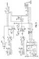
- FIG. 3is an electrical block diagram illustrating the circuitry of the hydraulic remote and hand control of the injector of FIG. 1 ;
- FIG. 4Ais an electrical block diagram of interface circuitry connected to the circuitry of FIG. 3 and other external sensors of the injector of FIG. 1 ;
- FIG. 4Bis an electrical block diagram of the processor and peripheral circuitry of the injector of FIG. 1 ;
- FIG. 4Cis an electrical block diagram of the watchdog system of the injector of FIG. 1 .
- the present inventionprovides a hand-held remote control which may be used with a medical injector to control the injection of fluids into a patient while providing tactile feedback to an operator of the injector. Furthermore, because the disposable components of the remote control are often available as off-the-shelf items, the cost of the disposable items are significantly reduced compared to currently available systems.
- an exemplary medical injector 10including an exemplary hand-held remote 12 of the present invention.
- One such medical fluid injectoris the Illumena model injector, available from Liebel-Flarsheim Company, Cincinnati, Ohio.
- the injector 10includes a power head 14 housing an internal drive motor, a hand-operated movement control lever 16 , and a display 18 for indicating to an operator the current status and operating parameters of the injector 10 .
- the power head 14may generally be supported on a carriage (not shown) by a mount 20 and an articulated support arm 22 , as described more fully in U.S. Pat. No.
- a syringe 24 including a syringe barrel 26 and a plunger 28may be mounted on the power head 14 to interface with the internal drive motor (not shown) of the injector 10 .
- the plunger 28is coupled to a plunger drive ram (not shown) of the motor whereby the motor may cause the syringe plunger 28 to move along the syringe barrel 26 to inject contents of the syringe 24 or to draw fluids into the barrel 26 via discharge tip 30 .
- the syringe 24may be surrounded by a pressure jacket 32 which supports the outer walls of the syringe barrel 26 .
- a heater blanket 34may be mounted on a post 36 which extends from the power head 14 , and abuts the exterior wall of pressure jacket 32 to heat the contents of the syringe 24 and maintain the temperature at approximately body temperature.
- the power head 14further comprises a housing made up of a first housing portion 40 a and a second housing portion 40 b which enclose the internal drive motor and a control circuit 42 for controlling the motor.
- Manipulation of the hand-operated movement control lever 16is sensed by the control circuit 42 to cause the plunger drive ram to inject or aspirate fluids from the syringe 24 , as more completely described in U.S. Pat. No. 5,925,022 to Battiato et al.
- the injector 10may be operated using the hydraulic remote 12 .
- remote 12includes a second syringe 50 , conveniently sized to be hand-held, and a conduit 52 connecting an outlet of the syringe 50 to the injector 10 .
- the conduit 52is a flexible tubing.
- Conduit 52is coupled to at least one pressure transducer 54 which, in turn, is coupled to the control circuit 42 of the injector 10 .
- the conduit 52is coupled to the pressure transducer 54 by a connector 55 which extends through an aperture 57 in the housing 40 .
- a second conduit 59extends from the connector to one or more pressure transducers 54 .
- the pressure transducer 54may either be provided directly on the control circuit 42 , or alternatively, may be provided on a circuit board 56 that may be connected to the control circuit 42 of the injector 10 .
- the circuit board 56 containing the pressure transducer 54may be configured to be connected to the control circuit 42 of the injector 10 at an interface 58 for receiving input from the control lever 16 .
- the circuit board 56may further include a connector 60 for receiving the input from the control lever 16 and adapted to be coupled to control lever 16 , such as by electrical leads 61 .
- Such a configurationadvantageously permits the medical injector 10 to be operated by either the control lever 16 or the hydraulic remote 12 .
- Pressure sensors 54 a and 54 bare active electromechanical transducers, which electrically form a balanced bridge. The potential across the bridge is reflective of the pressure being detected by the sensor 54 a and 54 b .
- Sensors 54 a and 54 bare each connected to differential amplifiers to apply gain to the differential voltage produced by the sensor.
- Differential amplifier 78 ais connected to sensor 54 a and produces a voltage, referenced to ground, in proportion to the magnitude of the pressure detected by sensor 54 a .
- Differential amplifier 78 bis connected to sensor 54 b , and also produces a voltage in proportion to the magnitude of the pressure detected by sensor 54 b .
- the voltage produced by amplifier 78 bis referenced to the analog voltage obtained from potentiometer 98 , for reasons to be explained below.
- the output of differential amplifier 78 ais coupled through a resistance R to the inverting input of a comparator 80 .
- the output of comparator 80is fed back to the noninverting input through a resistance 10 R, thus introducing a hysteresis in the response of comparator 80 .
- the noninverting input of comparator 80has a voltage of approximately 2.5 volts when the output of NAND gate 82 is a logic “low”, thus, in this condition, comparator 80 will produce a logic “high” signal whenever the input from differential amplifier 78 a slews above approximately 2.5 volts.
- the gain of differential amplifier 78 ais set so that an output of 2.5 volts is achieved whenever the pressure detected by pressure sensor 54 a is above a minimum threshold, indicative of the use of the hand syringe 50 to manually control an injection. This threshold prevents unintended manual operation of the injector from the limited hydraulic pressure present in the hand syringe 50 as initially installed on the injector.
- comparator 80When the pressure sensed by sensor 54 a exceeds the desired minimum threshold, and the output of NAND gate 82 is logic “low”, then comparator 80 will produce a logic “high” output, which enables operation of the hand syringe 50 for manual injection control.
- the output of comparator 80is coupled to a NAND gate wired as an inverter 86 , and the output of comparator 80 and NAND inverter 86 are connected to the control inputs of an analog multiplexer 88 .
- comparator 80produces a logic “high” output
- multiplexer 88delivers an analog signal from the output of differential amplifier 78 b to line 154 .
- comparator 80produces a logic “low” output
- multiplexer 88delivers an analog signal from the wiper of potentiometer 99 to line 154 .
- FIG. 3illustrates potentiometer 98 , which is connected between a reference voltage and ground to provide a voltage on line 99 indicative of the rotation of manual hand control 16 .
- Return springs 102 a and 102 b of the manual hand control, and a flag/contact connected to and rotating with the hand control,also form circuit elements in FIG. 3 .
- Return springs 102 a and 102 bare connected with a resistor 110 in a series connection between a digital +5 volt power supply and ground.
- a signal line 115 extending from between resistor 110 and spring 102 acarries a logic voltage signal indicating whether a current-carrying electrical contact is completed between springs 102 a and 102 b and flag/contact 104 . Under normal conditions, there should be an electrical path through this path to ground, holding the voltage on line 115 at a low level, indicating proper operation.
- the hand control 16further includes a detent spring 106 , which similarly forms an electrical contact in a series connection with a resistor 111 ; a detent signal line 116 extends from between resistor 111 and the detent spring. If control lever 16 is not rotated into the detent spring, line 116 will be pulled to a high level, indicating that the control lever 16 is not at the detent. However, if control lever 16 is rotated such that flag 105 contacts detent spring 106 , line 116 will be pulled to a low level, indicating that control lever 16 has been rotated to the detent.
- the signal on line 116may be used in several ways.
- the signalmay be used to calibrate the hand-operated control so that the angle of lever rotation corresponding to the detent is equal to the ideal fill speed.
- the signalmay be used to prevent reverse movement of the ram at a speed faster than the ideal fill speed.
- the signalmay be used to establish a “dead zone” of motion, in which the ram will move at the ideal fill speed, while permitting the lever to be rotated beyond the “dead zone” to produce faster reverse speeds.
- FIG. 3also illustrates the circuit details of a flag detector 108 ; a light emitting diode is energized with a bias current via resistor 113 ; when light passes through the gap in detector 108 and strikes the base of a phototransistor in detector 108 , the phototransistor draws current through resistor 112 to drive a home signal on line 117 to a low value, indicating that control lever 16 is not in its home position. Otherwise, if light is unable to pass to the base of the phototransistor in detector 108 , current is not drawn through resistor 112 and the home signal on line 117 is pulled to a high value, indicating that control lever 16 is in its home position.
- the circuitry on FIG. 3can thus use the home signal on line 117 to determine whether the hand control is in its home position.
- the home signalis connected through a NAND gate connected as an inverter 82 , to a voltage divider comprised of equal valued resistors 84 .
- the midpoint of resistors 84is connected to the inverting input of comparator 80 .
- the noninverting input of comparator 80is connected to the output of differential amplifier 78 a , as discussed above.
- the output of NAND gate 82 and the midpoint of resistors 84will have a logic “high” value.
- the output of comparator 80will have a logic “low” value regardless of the signal present at the output of differential amplifier 78 a .
- analog voltage on line 99 from the wiper of potentiometer 98is delivered through analog multiplexer 88 to line 154 .
- the output of comparator 80will have a logic “high” value and the analog voltage from differential amplifier 78 b is delivered through analog multiplexer 88 to line 154 .
- the analog voltage on line 154reflects the desired manual movement, whether indicated by rotation of the hand control 16 or by pressure on the hand syringe 50 .
- the voltage produced by differential amplifier 78 bis referenced to the analog voltage on line 99 from the wiper of potentiometer 98 . Since the hand syringe 50 is only enabled and may only be used while the hand control 16 is in its home position, this connection causes the voltage output by differential amplifier 78 b to be referenced to the same voltage produced by the potentiometer 98 on its wiper terminal 99 when in the home position.
- the analog voltage produced by differential amplifier 78 bdeviates from the same baseline voltage as the analog voltage produced by hand control 16 potentiometer 98 .
- a third “home” signalis also delivered to the microprocessor. This signal is produced by a first NAND gate 90 , via a second NAND gate 92 connected as an inverter, so that the “home” signal delivered to the microprocessor will have a “high” value whenever the hand control 16 is in its “home” position and the pressure sensed by sensor 54 a is below the established threshold (causing comparator 80 to produce a “low” output signal).
- the “home” signal output by NAND gate 92identifies those conditions where no manual movement is being requested either through hand control 16 or hand syringe 50 .
- the air detection moduleincorporates therein, a commercially available synchronous detection circuit 140 , which includes an internal oscillator generating trigger pulses on line 141 , and, contemporaneously with each trigger pulse, detects electrical signals on line 142 indicating that light has been received at light sensor 127 . So long as light is detected contemporaneously with each trigger pulse, a high level signal is produced on line 143 . Due to the application to which circuit 140 is applied in accordance with the invention, the signal on line 143 indicates whether air has been detected in the neck of the syringe 24 .
- the control circuit of power head 14may control the light intensity applied to the air bubble detector, to control the sensitivity of the detector. To do so, the control circuit produces a pulse width modulated (PWM) digital signal on line 145 . This PWM signal is filtered by a low-pass filter circuit 146 to produce an analog control voltage, which controls an adjustable regulator 147 to produce the power signal on line 148 for circuit 140 .
- PWMpulse width modulated
- a PNP opto-transistor 149In response to the trigger signal on line 141 , a PNP opto-transistor 149 is turned “on”, causing the power signal on line 148 to energize light source 126 .
- the voltage of the power signal on line 148directly affects the intensity of light generated by light source 126 .
- the trigger signal on line 141is connected to the base of PNP opto-transistor 149 via a light emitting diode in an opto-isolator 150 . Accordingly, the opto-transistor in opto-isolator 150 will turn “on” whenever the trigger signal is activated, causing a “low” level to appear on line 151 . Thus, if the synchronous air detector circuit 140 is operating properly and producing periodic trigger signals, pulses will appear on line 151 , which can be detected by the control circuit to verify that the oscillator in circuit 140 is operating properly.
- FIG. 4Aalso illustrates the analog-to-digital (A/D) converter 152 incorporated into the power head control circuit for quantizing analog signals produced by various electrical elements.
- A/D converter 152converts the analog voltage on line 154 to a digital signal on a “SPI” serial interface bus 156 , upon request from the CPU (see FIG. 4B ), so that the CPU can determine the position of hand control 16 or pressure in the hand syringe 50 and react accordingly.
- A/D converter 152converts the analog voltage on line 154 to a digital signal on a “SPI” serial interface bus 156 , upon request from the CPU (see FIG. 4B ), so that the CPU can determine the position of hand control 16 or pressure in the hand syringe 50 and react accordingly.
- A/D converter 152Other analog voltages are also input to A/D converter 152 .
- a single-chip accelerometeris configured as a tilt sensor 158 , to produce an analog voltage on line 159 indicative of the angle of tilt of sensor 158 .
- a suitable single chip accelerometer for this purposeis available from Analog Devices of Norwood, Mass. as part no. ADXL05AH.
- Sensor 158is mounted to circuit board 55 , and therefore produces an output voltage indicative of the tilt of power head 14 relative to the direction of Earth gravity. This analog tilt signal is converted and input to the CPU for use, as noted below; in controlling the display and other operational features of power head 14 .
- a third analog signalis produced by a linear potentiometer 160 , the wiper of which is mechanically connected to the plunger drive ram, and moved in response to movement of the plunger drive ram.
- the voltage of the wiper on line 161is an analog signal representative of the position of the ram between its rearward most and forward most positions. This signal is converted and used by the CPU to determine the position of the ram and, among other things, the syringe volume remaining.
- thermistors 163 A and 163 bTwo additional analog signals are produced by thermistors 163 A and 163 b , which are series connected with bias resistors to produce voltages on lines 164 a and 164 b which reflect the temperature of the thermistors.
- the temperature measurement obtained from these thermistorsis then used to control the power applied through the heater blanket 34 to warm the fluid in the syringe 24 .
- the heat power applied to the syringeis varied proportion to the ambient temperature, as measured by thermistors 163 a and 164 a , to maintain the fluid at the target temperature, e.g., 30 degrees Celsius.
- Thermistors 163 a and 163 bare duplicative, that is, both measure the same temperature and their measurements are compared to ensure near agreement. As a result, failure of a thermistor can be detected from disagreement between the temperature readings obtained from the thermistors, preventing loss of temperature control.
- Thermistors 163 a and 163 bmay be mounted internally to power head 14 , on circuit board 42 .
- thermistors 163 a and 163 bmay be external to the housing, to ensure more accurate temperature readings, or both options may be allowed by providing internally-mounted thermistors which can be disabled if substitute externally-mounted thermistors are connected to the power head 14 .
- power head 14controls the heat power applied to the syringe 24 through heater blanket 34 .
- the CPU(see FIG. 4B ) produces a pulse width modulated (PWM) control signal on line 166 which is used to control the heat power applied to the heater blanket filament 120 .
- PWMpulse width modulated
- the PWM signal on line 166is low pass filtered by filter 167 , producing an analog control signal which controls an adjustable regulator 168 .
- the output of regulator 168 on line 169is a variable voltage which is applied across heater blanket filament 120 , causing heater filament 120 to produce heat.
- An instrumentation amplifier 170filters and conditions the voltage across filament 120 to produce an analog output signal on line 171 which is proportional to the voltage applied to the heater blanket filament 120 .
- a sense resistor 173is series connected with heater filament 120 , so that the current in heater filament 120 passes through sense resistor 173 , producing a voltage on sense resistor proportional to the current flowing through heater filament 120 .
- Sense resistorhas a resistance substantially smaller than that of heater filament 120 , so that the small voltage drop across sense resistor 173 is not a substantial percentage of the voltage drop across heater filament 120 .
- the voltage drop across sense resistor 173is amplified and filtered by a gain/filter circuit 172 , producing an analog voltage on line 174 which is proportional to the current flowing through heater filament 120 .
- Lines 171 and 174are connected to A/D converter 152 , and the voltages on lines 171 and 174 are converted thereby to digital signals which can be read by the CPU. Accordingly, the CPU can determine the current and voltage drop across heater filament 120 , and use these values to determine the heat output of heater filament 120 . This permits the CPU to perform closed-loop control of the heater blanket heat output, as discussed more thoroughly in U.S. Pat. No. 5,925,022.
- the CPU 175which may be a 68332 microprocessor, available from Motorola, controls data and address busses 176 connecting CPU 175 to random access memory (RAM) 178 and a flash memory 177 .
- CPU 175also controls an SPI serial interface bus 156 for communicating with A/D converter 152 , display 30 and a monitor microcontroller 192 .
- CPU 175further includes an RS-422 serial interface 179 connecting CPU 175 to a CPU in the power pack (see FIG. 4C ).
- CPU 175includes a number of digital data input lines for monitoring operation of power head 14 . Specifically, CPU 175 receives the detent signal on line 116 , safe signal on line 115 and home signal on line 117 , enabling CPU to receive input on the state of operation of the hand-operated controls (lever and syringe) as discussed above. CPU 175 also receives the bubble signal on line 143 from which CPU 175 may detect air in the syringe neck and take appropriate action, and in addition, CPU 175 receives the bubble detection oscillator signal on line 151 , which can be used as noted above to confirm proper operation of the oscillator in the air detection module 122 .
- CPU 175receives the output of flag sensor 63 , from which CPU 175 may determine whether the face plate is securely locked to the housing of power head 14 . Furthermore, CPU 175 receives digital signals from the three magnetic detectors 57 a , 57 b and 57 c indicative of which of several possible face plates are mounted to power head 14 , allowing CPU 175 to adjust its operation accordingly.
- CPU 175also receives digital input signals from parallel rotary encoders 182 , which produce pulse signals on lines 183 a and 183 b indicative of rotation of the plunger drive train. These pulses are used by CPU 175 to confirm movement of the plunger drive ram. Lines 183 a and 183 b are also connected to the power pack (see FIG. 4C ) so that the power pack CPU may perform closed loop control of plunger movement by counting encoder pulses and comparing the rate of receipt of encoder pulses to a desired rate.
- a closed loop controlis disclosed in U.S. Pat. No. 4,812,724, which is incorporated by reference herein in its entirety.
- CPU 175also produces multiple digital control signals, including those noted above, i.e., the air bubble detector power PWM signal on line 145 , and the heater blanket power PWM signal on line 166 , both being pulse-width modulated by CPU 175 to produce desired power levels.
- CPU 175further produces output signals on lines 187 for illuminating light emitting diodes in lamp 45 ( FIG. 2 ) which indicate the status of operation of the injector. Additional output signals on SPI serial bus lines 156 control the display 30 .
- CPU 175uses the above-noted inputs and outputs to perform primary control of power head 14 under control of software resident in CPU 175 or read from RAM 178 .
- CPU 175is also connected, through SPI serial bus 156 , to a microcontroller 192 which serves as a monitor, for monitoring operation of CPU 175 to ensure the absence of software or hardware failures.
- Monitor microcontroller 192performs this function by receiving, through bus 156 , an indication of the current operational state of CPU 175 .
- CPU 175indicates, through bus 156 , the operating state of CPU 175 , i.e., whether CPU 175 is requesting movement of the plunger or not, and whether the motion is being requested in response to hand-operated or automatic (programmed) control, and potentially other specific information such as the rate of movement that is being requested.
- Monitor microcontroller 192reads this state information from lines 156 , and compares this information to crucial digital input signals from the power head 14 , to ensure consistency therebetween.
- microcontroller 192receives the safe signal on line 115 and home signal on line 117 . If these signals indicate that the hand-operated controls are not being used, then CPU 175 should not be generating movement under hand-operated control. If a spring has failed (as indicated by the signal on line 115 ), this should be reflected in the state of the CPU 175 . Therefore, under these conditions, microcontroller 192 reads the state information from bus 156 to ensure that CPU 175 is not acting inconsistently with the signals from the hand-operated controls.
- microcontroller 192receives the output signals from rotary encoders 182 on lines 183 a and 183 b . Microcontroller 192 checks these signals to determine whether the plunger drive ram is moving, to ensure the drive ram is moving only when the state of CPU 175 indicates that the drive ram should be moving, and not otherwise. Furthermore, in this connection it should be noted that microcontroller 192 receives the door flag signal from door flag sensor 63 . If this signal indicates that the door of power head 14 is other than in the locked position, CPU 175 should not be requesting movement of the plunger drive ram, and microcontroller 192 confirms this by checking for the absence of pulses from encoders 182 .
- each of power head 14 , power pack 47 and console 25contains a CPU 175 , 192 and 194 , respectively.
- These CPUsinteract through external interfaces to perform control of the injector.
- the plunger drive ramcan be controlled through the lever 16 on power head 14 (as discussed above), or can be automatically controlled by an operator entering programs for injections using touch screen 33 of console 25 (using CPU 194 ), and then enabling the programmed injection.
- the injection parameterssuch as motor speed and injection volumes will then be produced by console CPU 194 , which communicates with power pack CPU 192 to cause these programmed actions to take place.
- an automatic injectionmay be enabled using the touch screen 33 , or an injection may be started using a hand switch or OEM remote trigger connected to power pack 47 . In either case, the appropriate one of CPUs 192 and 194 generates an enabling signal to initiate the automatic injection.
- the power head CPU 175is associated with a monitor microcontroller 192 for monitoring the state of CPU 175 to ensure its actions are consistent with input signals from power head 14 .
- CPUs 192 and 194are also associated with monitor microcontrollers 196 and 198 , respectively, which monitor the actions of the associated CPUs 196 and 198 to ensure consistent, error free behavior.
- Monitor microcontrollers 192 , 196 and 198communicate with each other in a manner which parallels the communication of CPUs 175 , 192 and 194 .
- the three monitor microcontrollersexchange state information received from their associated CPUs to ensure that the three CPUs are in similar states of operation; e.g., hand-operated movement, automatic movement, no movement, etc.
- each of the microcontrollersreceives external input signals to ensure that state transitions which should occur are, in fact, occurring.
- microcontroller 196receives the hand or OEM trigger signals so that microcontroller 196 can determine when an automatic injection has been triggered.
- Microcontroller 198receives input signals from touch screen 33 so it, too, can determine when an automatic injection has been triggered.
- Other monitoring functionscan be performed, as desired to ensure correct and consistent operation of CPUs 175 , 192 and 194 .
- power head CPU 175delivers a control signal to power pack 47 , requesting a ram movement.
- Power pack 47contains the motor servo control circuitry for producing an appropriate power signal on line 200 to the drive motor M, and to perform closed loop control of motor movements in response to encoder pulses on lines 183 .
- the monitor microcontrollerscan discontinue power flow to the motor M through a hardware disable, represented by switch 202 in series with power line 200 , thereby ceasing any movement of the plunger drive.
- This hardware disableensures that the monitor microcontrollers can prevent erroneous injection of fluid under error conditions.
- the hydraulic remote 12may be used to control the injection of fluids by the medical injector 10 when a plunger 62 on the remote 12 is moved into a syringe body 64 of the remote 12 .
- the syringe 50 and conduit 52are filled with air whereby motion of the plunger 62 creates a pressure which is sensed by the pressure transducer 54 .
- the pressure transducer 54senses a positive change in pressure from the remote 12 .
- the control circuit 42 of the injector 10causes the drive motor to move the plunger drive ram into the syringe 24 on the power head 14 to expel fluid from the syringe 24 .
- the control circuit 42causes the plunger drive ram to expel fluid from the syringe 24 at a rate that is related to the amount of pressure change sensed by the pressure transducer 54 .
- the plunger drive ramis moved at a rate proportional to the amount of pressure change.
- two pressure transducers 54 a , 54 bare coupled to the control circuit 42 of the injector to sense pressure from the hydraulic remote 12 .
- the control circuit 42responds to the pressure sensed by a first of the pressure transducers 54 b to control the motion of the plunger drive ram into the syringe 24 , as described above.
- the pressure sensed by the second of the transducers 54 ais compared by the control circuit 42 to a threshold pressure above which the injector 10 is enabled and below which the injector 10 is inoperable. This configuration allows the injections to be stopped when an operator releases the plunger 62 on the hydraulic remote 12 .
- the hydraulic remote 12may include a feature permitting the plunger 62 to be retracted from within the syringe body 64 of the remote 12 .
- the plunger 62may include a thumb ring which permits an operator to pull as well as push on the plunger 62 . Because the syringe 50 and conduit 52 described herein may be available as off-the-shelf items and therefore readily available, these components of the remote 12 are relatively inexpensive and therefore introduce minimal cost when used as disposable items.
- Medical injectorswhich are presently in use may be modified to use the hydraulic remote 12 of the present invention by incorporation of a circuit board 56 having at least one pressure transducer 54 , as described above.
- the circuit board 56may generally be added to an existing unit's control circuit 42 to permit the injector 10 to operate with the hydraulic remote 12 and with minimal or no impact to existing software.
- FIG. 2shows an exemplary electronic circuit board, including at least one pressure transducer 54 , which may be added to existing control circuits 42 of medical injectors 10 to enable the injector 10 to operate with the hydraulic remote 12 , as described above.
- a method of controlling a medical fluid injector 10 using a hydraulic remote 12 as described aboveincludes the steps of moving a plunger 62 of the hydraulic remote 12 to generate a pressure, sensing the pressure generated by the hydraulic remote 12 and moving a plunger drive ram on the injector 10 in response to the sensed pressure, whereby the medical fluid injector 10 ejects fluid from a syringe 24 coupled to the injector 10 unit.
- the control circuit 42causes the plunger drive ram to eject fluid from the syringe 26 on the injector 10 unit at a maximum rate of about 6 ml/sec in response to a pressure sensed by the pressure transducer 54 .
- the medial injector 10has been described herein as being configured to inject fluids into a patient in response to movement of the plunger 62 on the hydraulic remote 12 into the syringe body 64 , it is also contemplated that the medical injector 10 could also be configured to aspirate fluids from a patient in response to movement of the plunger 62 out of syringe body 64 .
- the injector 10could be configured to perform either of these functions, solely or selectively, according to the desired operation. For example, it may be desired to aspirate a small amount of blood from a patent upon initial catheterization to confirm that the intravascular space has been entered.
Landscapes
- Health & Medical Sciences (AREA)
- Engineering & Computer Science (AREA)
- Anesthesiology (AREA)
- Biomedical Technology (AREA)
- Heart & Thoracic Surgery (AREA)
- Hematology (AREA)
- Life Sciences & Earth Sciences (AREA)
- Animal Behavior & Ethology (AREA)
- General Health & Medical Sciences (AREA)
- Public Health (AREA)
- Veterinary Medicine (AREA)
- Infusion, Injection, And Reservoir Apparatuses (AREA)
- Measurement Of The Respiration, Hearing Ability, Form, And Blood Characteristics Of Living Organisms (AREA)
Abstract
Description
Claims (21)
Priority Applications (2)
| Application Number | Priority Date | Filing Date | Title |
|---|---|---|---|
| US10/924,302US8118780B2 (en) | 2002-05-15 | 2004-08-23 | Hydraulic remote for a medical fluid injector |
| US13/369,407US9375557B2 (en) | 2002-05-15 | 2012-02-09 | Hydraulic remote for a medical fluid injector |
Applications Claiming Priority (2)
| Application Number | Priority Date | Filing Date | Title |
|---|---|---|---|
| US10/146,696US6780170B2 (en) | 2002-05-15 | 2002-05-15 | Hydraulic remote for a medical fluid injector |
| US10/924,302US8118780B2 (en) | 2002-05-15 | 2004-08-23 | Hydraulic remote for a medical fluid injector |
Related Parent Applications (1)
| Application Number | Title | Priority Date | Filing Date |
|---|---|---|---|
| US10/146,696DivisionUS6780170B2 (en) | 2002-05-15 | 2002-05-15 | Hydraulic remote for a medical fluid injector |
Related Child Applications (1)
| Application Number | Title | Priority Date | Filing Date |
|---|---|---|---|
| US13/369,407DivisionUS9375557B2 (en) | 2002-05-15 | 2012-02-09 | Hydraulic remote for a medical fluid injector |
Publications (2)
| Publication Number | Publication Date |
|---|---|
| US20050027238A1 US20050027238A1 (en) | 2005-02-03 |
| US8118780B2true US8118780B2 (en) | 2012-02-21 |
Family
ID=29418869
Family Applications (3)
| Application Number | Title | Priority Date | Filing Date |
|---|---|---|---|
| US10/146,696Expired - LifetimeUS6780170B2 (en) | 2002-05-15 | 2002-05-15 | Hydraulic remote for a medical fluid injector |
| US10/924,302Expired - Fee RelatedUS8118780B2 (en) | 2002-05-15 | 2004-08-23 | Hydraulic remote for a medical fluid injector |
| US13/369,407Expired - Fee RelatedUS9375557B2 (en) | 2002-05-15 | 2012-02-09 | Hydraulic remote for a medical fluid injector |
Family Applications Before (1)
| Application Number | Title | Priority Date | Filing Date |
|---|---|---|---|
| US10/146,696Expired - LifetimeUS6780170B2 (en) | 2002-05-15 | 2002-05-15 | Hydraulic remote for a medical fluid injector |
Family Applications After (1)
| Application Number | Title | Priority Date | Filing Date |
|---|---|---|---|
| US13/369,407Expired - Fee RelatedUS9375557B2 (en) | 2002-05-15 | 2012-02-09 | Hydraulic remote for a medical fluid injector |
Country Status (5)
| Country | Link |
|---|---|
| US (3) | US6780170B2 (en) |
| EP (1) | EP1503815A4 (en) |
| JP (2) | JP4327083B2 (en) |
| AU (1) | AU2003229057A1 (en) |
| WO (1) | WO2003097128A1 (en) |
Cited By (3)
| Publication number | Priority date | Publication date | Assignee | Title |
|---|---|---|---|---|
| US9480788B2 (en) | 2012-11-30 | 2016-11-01 | Acist Medical Systems, Inc. | Medical injection systems and methods related to user activated control devices |
| USD806233S1 (en) | 2016-09-09 | 2017-12-26 | Liebel-Flarsheim Company Llc | Powerhead for a power injection system |
| US11951283B2 (en) | 2020-07-17 | 2024-04-09 | Acist Medical Systems, Inc. | Hand-control device for controlling operation of injection system |
Families Citing this family (62)
| Publication number | Priority date | Publication date | Assignee | Title |
|---|---|---|---|---|
| US7572263B2 (en) | 1998-04-01 | 2009-08-11 | Arthrocare Corporation | High pressure applicator |
| US6783515B1 (en) | 1999-09-30 | 2004-08-31 | Arthrocare Corporation | High pressure delivery system |
| US6780170B2 (en)* | 2002-05-15 | 2004-08-24 | Liebel-Flarsheim Company | Hydraulic remote for a medical fluid injector |
| EP1542616B1 (en)* | 2002-09-20 | 2015-04-22 | Endologix, Inc. | Stent-graft with positioning anchor |
| US7291131B2 (en)* | 2003-05-05 | 2007-11-06 | Physicians Industries, Inc. | Infusion syringe |
| US7351223B2 (en)* | 2003-05-05 | 2008-04-01 | Physicians Industries, Inc. | Infusion syringe with integrated pressure transducer |
| US7621892B2 (en)* | 2003-12-31 | 2009-11-24 | Mallinckrodt Inc. | Contrast container holder and method to fill syringes |
| USD579561S1 (en) | 2004-01-30 | 2008-10-28 | Physician Industries, Inc. | Portion of a syringe |
| USD562447S1 (en) | 2004-01-30 | 2008-02-19 | Physician Industries, Inc. | Portion of a syringe |
| US8235256B2 (en)* | 2004-02-12 | 2012-08-07 | Kyphon Sarl | Manual pump mechanism and delivery system |
| US7491191B2 (en)* | 2004-02-13 | 2009-02-17 | Liebel-Flarsheim Company | Keep vein open method and injector with keep vein open function |
| US8048145B2 (en) | 2004-07-22 | 2011-11-01 | Endologix, Inc. | Graft systems having filling structures supported by scaffolds and methods for their use |
| US7507221B2 (en)* | 2004-10-13 | 2009-03-24 | Mallinckrodt Inc. | Powerhead of a power injection system |
| US20060133193A1 (en)* | 2004-12-17 | 2006-06-22 | Arthrocare Corporation | High pressure injection system for delivering therapeutic agents having fluid tight connector |
| EP1912135B1 (en) | 2005-04-06 | 2010-09-15 | Mallinckrodt, Inc. | System and methods for managing information relating to medical fluids and containers therefor |
| JP2009500121A (en) | 2005-07-07 | 2009-01-08 | ネリックス・インコーポレーテッド | System and method for treatment of an intraluminal aneurysm |
| EP2468351B1 (en)* | 2005-11-21 | 2019-01-09 | ACIST Medical Systems, Inc. | Medical fluid injection system |
| US20070150041A1 (en)* | 2005-12-22 | 2007-06-28 | Nellix, Inc. | Methods and systems for aneurysm treatment using filling structures |
| US20090124996A1 (en)* | 2006-11-03 | 2009-05-14 | Scott Heneveld | Apparatus and methods for injecting high viscosity dermal fillers |
| US20080306443A1 (en)* | 2007-06-06 | 2008-12-11 | Mallinckrodt Inc. | Medical Fluid Injector Having Wireless Pressure Monitoring Feature |
| US8141417B2 (en)* | 2007-08-23 | 2012-03-27 | Mallinckrodt Llc | Syringe content detection using RF energy |
| US8002753B2 (en) | 2007-12-21 | 2011-08-23 | Nordson Corporation | Self-contained pressurized injection device |
| WO2009091851A2 (en)* | 2008-01-18 | 2009-07-23 | Mallinckrodt Inc. | Medical fluid injector with auto-calibration based on system wear and usage |
| EP2278939B1 (en) | 2008-04-25 | 2021-04-14 | Endologix LLC | Stent graft delivery system |
| AU2009244925B2 (en) | 2008-05-07 | 2014-03-27 | Jolife Ab | CPR apparatus and method |
| EP2299931B1 (en)* | 2008-06-04 | 2020-01-08 | Endologix, Inc. | Sealing apparatus |
| US20100103765A1 (en)* | 2008-10-24 | 2010-04-29 | Hornbostel Marc D | Liquid injector for silicon production |
| JP2012525239A (en) | 2009-05-01 | 2012-10-22 | エンドロジックス、インク | Transcutaneous methods and devices for treating dissociation (priority information and incorporation by reference) |
| US10772717B2 (en) | 2009-05-01 | 2020-09-15 | Endologix, Inc. | Percutaneous method and device to treat dissections |
| EP2456572B1 (en) | 2009-07-24 | 2014-02-26 | BAYER Medical Care Inc. | Multi-fluid medical injector system |
| WO2011017123A2 (en) | 2009-07-27 | 2011-02-10 | Endologix, Inc. | Stent graft |
| US20120157895A1 (en)* | 2009-08-26 | 2012-06-21 | The University Of Kansas | Device, system, and method for mechanosensory nerve ending stimulation |
| KR101031013B1 (en)* | 2009-11-30 | 2011-04-25 | 삼성메디슨 주식회사 | Locking device and medical device having same |
| US20110276078A1 (en) | 2009-12-30 | 2011-11-10 | Nellix, Inc. | Filling structure for a graft system and methods of use |
| US9789247B2 (en) | 2011-12-21 | 2017-10-17 | Deka Products Limited Partnership | Syringe pump, and related method and system |
| US9295778B2 (en) | 2011-12-21 | 2016-03-29 | Deka Products Limited Partnership | Syringe pump |
| US9744300B2 (en) | 2011-12-21 | 2017-08-29 | Deka Products Limited Partnership | Syringe pump and related method |
| US9393100B2 (en) | 2010-11-17 | 2016-07-19 | Endologix, Inc. | Devices and methods to treat vascular dissections |
| CA2818224C (en)* | 2010-11-24 | 2019-10-29 | Mallinckrodt Llc | Medical fluid injector system |
| US8801768B2 (en) | 2011-01-21 | 2014-08-12 | Endologix, Inc. | Graft systems having semi-permeable filling structures and methods for their use |
| EP2693980B1 (en) | 2011-04-06 | 2022-07-13 | Endologix LLC | System for endovascular aneurysm treatment |
| EP2707049B1 (en)* | 2011-05-12 | 2019-07-03 | Bayer Healthcare LLC | Fluid injection system having various systems for controlling an injection procedure |
| US11217340B2 (en) | 2011-12-21 | 2022-01-04 | Deka Products Limited Partnership | Syringe pump having a pressure sensor assembly |
| US10722645B2 (en) | 2011-12-21 | 2020-07-28 | Deka Products Limited Partnership | Syringe pump, and related method and system |
| US12131826B2 (en) | 2011-12-21 | 2024-10-29 | Deka Products Limited Partnership | Syringe pump and related method |
| BR112015022688B1 (en) | 2013-03-14 | 2020-10-06 | Endologix, Inc. | METHOD FOR FORMING A MATERIAL IN SITU THROUGH INCREASING THE VOLUME OF AN EXPANDABLE MEMBER OF A MEDICAL DEVICE |
| WO2015073381A1 (en) | 2013-11-14 | 2015-05-21 | Epic Medical Concepts & Innovations, Inc. | Pneumatic somatosensory stimulation device and method |
| CN104964088B (en)* | 2013-11-25 | 2020-10-16 | 费希尔控制国际公司 | Method and apparatus for diagnosing a valve using an electronic valve actuator |
| WO2015127189A1 (en) | 2014-02-21 | 2015-08-27 | Deka Products Limited Partnership | Syringe pump having a pressure sensor assembly |
| US11246796B2 (en) | 2014-06-06 | 2022-02-15 | Physio-Control, Inc. | Adjustable piston |
| US10004662B2 (en) | 2014-06-06 | 2018-06-26 | Physio-Control, Inc. | Adjustable piston |
| EP3253329A4 (en)* | 2015-02-02 | 2018-02-28 | GT Urological, LLC | Hydraulic urethral occlusive device |
| US20170151286A1 (en)* | 2015-12-01 | 2017-06-01 | Invivo Therapeutics Corporation | Compositions and methods for preparing an injectable medium for administration into the central nervous system |
| EP3481462B1 (en)* | 2016-07-06 | 2021-03-24 | Bayer Healthcare LLC | Contrast heating system with in-line contrast warmer |
| CN110546713B (en) | 2017-03-15 | 2023-10-27 | 诺瓦提斯公司 | Medical device, programming device, wireless terminal, and medical system |
| AU2018317866B2 (en) | 2017-08-18 | 2024-06-13 | Bayer Healthcare Llc | System, method, and computer program product for predictive maintenance |
| CN113710369B (en)* | 2019-04-18 | 2022-11-25 | Smc 株式会社 | High-pressure fluid ejection device |
| US20220054751A1 (en)* | 2019-07-18 | 2022-02-24 | Osprey Medical, Inc. | Modulated power injector with input device |
| WO2021229567A1 (en)* | 2020-05-12 | 2021-11-18 | EndoWays LTD. | Apparatus for injection by remote control with feedback, and method |
| EP4153266A2 (en)* | 2020-05-19 | 2023-03-29 | Bayer HealthCare, LLC | Smart injector turn knobs |
| JP2024513779A (en)* | 2021-03-26 | 2024-03-27 | オスプリー メディカル,インコーポレイティド | Modulated power injector with input device |
| CN114860643B (en)* | 2022-04-25 | 2025-04-04 | 上海莘汭驱动技术有限公司 | A controllable multi-channel load control system |
Citations (46)
| Publication number | Priority date | Publication date | Assignee | Title |
|---|---|---|---|---|
| US3623474A (en) | 1966-07-25 | 1971-11-30 | Medrad Inc | Angiographic injection equipment |
| US4006736A (en) | 1974-11-27 | 1977-02-08 | Medrad, Inc. | Angiographic injector |
| US4085749A (en)* | 1976-01-14 | 1978-04-25 | Compagnie Generale De Radiologie | Method and apparatus for controlling the movement of fluid to and from a syringe |
| US4325399A (en)* | 1979-11-15 | 1982-04-20 | Rosemount Inc. | Current to pressure converter apparatus |
| US4551133A (en)* | 1984-04-16 | 1985-11-05 | American Hospital Supply Corporation | Patient controlled medication infusion system |
| US4624658A (en)* | 1983-11-09 | 1986-11-25 | Intermedicat Gmbh | Distensible syringe and sensor for injectors |
| US4749109A (en) | 1983-11-15 | 1988-06-07 | Kamen Dean L | Volumetric pump with replaceable reservoir assembly |
| US4854324A (en)* | 1984-01-31 | 1989-08-08 | Medrad, Inc. | Processor-controlled angiographic injector device |
| GB2222952A (en) | 1988-09-23 | 1990-03-28 | Vnii Glaznykh Boleznei | Ophthalmologlcal device |
| US4955558A (en)* | 1988-02-11 | 1990-09-11 | British Aerospace Public Limited Company | Reaction control system |
| US4976696A (en)* | 1987-08-10 | 1990-12-11 | Becton, Dickinson And Company | Syringe pump and the like for delivering medication |
| US5004472A (en)* | 1988-08-10 | 1991-04-02 | Wallace William D | Medical pressure sensing and display system |
| US5019037A (en) | 1989-07-06 | 1991-05-28 | Alcon Laboratories, Inc. | Pneumatic retinopexy injector |
| US5045833A (en) | 1989-05-30 | 1991-09-03 | Smith Edward R | Apparatus and system for alerting deaf persons |
| US5140862A (en)* | 1991-02-06 | 1992-08-25 | Pappalardo Joseph T | Injection pump calibration device |
| US5244463A (en) | 1991-12-06 | 1993-09-14 | Block Medical, Inc. | Programmable infusion pump |
| US5269762A (en)* | 1992-04-21 | 1993-12-14 | Sterling Winthrop, Inc. | Portable hand-held power assister device |
| US5342298A (en)* | 1992-07-31 | 1994-08-30 | Advanced Cardiovascular Systems, Inc. | Automated fluid pressure control system |
| US5370123A (en)* | 1991-02-04 | 1994-12-06 | Nissho Corporation | Blood clarification apparatus |
| US5383858A (en) | 1992-08-17 | 1995-01-24 | Medrad, Inc. | Front-loading medical injector and syringe for use therewith |
| US5383855A (en)* | 1992-08-20 | 1995-01-24 | Medex, Inc. | Electronically monitored angioplasty system |
| US5423759A (en) | 1992-11-02 | 1995-06-13 | Infusion Technologies Corporation | Valve system and method for control of an infusion pump |
| US5423746A (en)* | 1991-08-05 | 1995-06-13 | Imed Corporation | Method and apparatus for infiltration detection during administration of intravenous fluids |
| US5431629A (en) | 1989-03-17 | 1995-07-11 | Merit Medical Systems, Inc. | System and method for monitoring, displaying and recording balloon catheter condition interval data |
| US5449345A (en)* | 1989-03-17 | 1995-09-12 | Merit Medical Systems, Inc. | Detachable and reusable digital control unit for monitoring balloon catheter data in a syringe inflation system |
| US5573515A (en) | 1995-04-20 | 1996-11-12 | Invasatec, Inc. | Self purging angiographic injector |
| US5630527A (en)* | 1994-09-12 | 1997-05-20 | Philip Fishman Corporation | Electronically controlled, positive-displacement fluid dispenser |
| US5700245A (en)* | 1995-07-13 | 1997-12-23 | Winfield Medical | Apparatus for the generation of gas pressure for controlled fluid delivery |
| US5704912A (en)* | 1995-03-17 | 1998-01-06 | Advanced Cardiovascular Systems, Inc. | Syringe assembly mounting system for inflation control system |
| US5733230A (en) | 1996-02-21 | 1998-03-31 | Sawchuck; Diane J. | Perineometer for domestic use in prevention of urinary incontinence and method of using the same |
| US5800397A (en) | 1995-04-20 | 1998-09-01 | Invasatec, Inc. | Angiographic system with automatic high/low pressure switching |
| WO1998042257A1 (en) | 1997-03-24 | 1998-10-01 | Izex Technologies, Inc. | Orthoses |
| US5868710A (en) | 1996-11-22 | 1999-02-09 | Liebel Flarsheim Company | Medical fluid injector |
| US5882343A (en) | 1995-04-20 | 1999-03-16 | Invasatec, Inc. | Dual port syringe |
| US5899880A (en)* | 1994-04-08 | 1999-05-04 | Powderject Research Limited | Needleless syringe using supersonic gas flow for particle delivery |
| US5916165A (en) | 1997-11-06 | 1999-06-29 | Invasatec, Inc. | Pneumatic controller and method |
| US6010478A (en)* | 1995-02-14 | 2000-01-04 | Powderject Research Limited | Trans-mucosal particle delivery |
| US6050450A (en)* | 1998-12-28 | 2000-04-18 | Dispensing Technologies International Incorporated | Apparatus and system for precision dispensing of fluids and method of operating the same |
| US6099502A (en) | 1995-04-20 | 2000-08-08 | Acist Medical Systems, Inc. | Dual port syringe |
| US6171276B1 (en)* | 1997-08-06 | 2001-01-09 | Pharmacia & Upjohn Ab | Automated delivery device and method for its operation |
| US6179569B1 (en)* | 1997-01-10 | 2001-01-30 | Japan Servo Co., Ltd. | Liquid transportation apparatus |
| US6206868B1 (en)* | 1998-03-13 | 2001-03-27 | Arteria Medical Science, Inc. | Protective device and method against embolization during treatment of carotid artery disease |
| US6221045B1 (en) | 1995-04-20 | 2001-04-24 | Acist Medical Systems, Inc. | Angiographic injector system with automatic high/low pressure switching |
| US6780170B2 (en) | 2002-05-15 | 2004-08-24 | Liebel-Flarsheim Company | Hydraulic remote for a medical fluid injector |
| US7044933B2 (en)* | 2001-03-01 | 2006-05-16 | Scimed Life Systems, Inc. | Fluid injection system for coronary intervention |
| US7296566B2 (en)* | 1999-10-14 | 2007-11-20 | Becton, Dickinson And Company | Nasal delivery device including spray nozzle |
Family Cites Families (5)
| Publication number | Priority date | Publication date | Assignee | Title |
|---|---|---|---|---|
| US4812724A (en) | 1984-11-13 | 1989-03-14 | Liebel-Flarsheim Corporation | Injector control |
| US5383856A (en) | 1993-03-19 | 1995-01-24 | Bersin; Robert M. | Helical spiral balloon catheter |
| US7566320B2 (en)* | 2001-02-14 | 2009-07-28 | Acist Medical Systems, Inc. | Fluid injector system |
| US6821013B2 (en)* | 2001-12-20 | 2004-11-23 | Medrad, Inc. | Adapters, adapter systems and method for use in connection with powered injectors for agitation of multi-component fluids |
| US8066713B2 (en)* | 2003-03-31 | 2011-11-29 | Depuy Spine, Inc. | Remotely-activated vertebroplasty injection device |
- 2002
- 2002-05-15USUS10/146,696patent/US6780170B2/ennot_activeExpired - Lifetime
- 2003
- 2003-05-13JPJP2004505123Apatent/JP4327083B2/ennot_activeExpired - Fee Related
- 2003-05-13WOPCT/US2003/015034patent/WO2003097128A1/enactiveApplication Filing
- 2003-05-13AUAU2003229057Apatent/AU2003229057A1/ennot_activeAbandoned
- 2003-05-13EPEP03726838Apatent/EP1503815A4/ennot_activeWithdrawn
- 2004
- 2004-08-23USUS10/924,302patent/US8118780B2/ennot_activeExpired - Fee Related
- 2009
- 2009-04-16JPJP2009100407Apatent/JP2009183744A/ennot_activeWithdrawn
- 2012
- 2012-02-09USUS13/369,407patent/US9375557B2/ennot_activeExpired - Fee Related
Patent Citations (51)
| Publication number | Priority date | Publication date | Assignee | Title |
|---|---|---|---|---|
| US3623474A (en) | 1966-07-25 | 1971-11-30 | Medrad Inc | Angiographic injection equipment |
| US4006736A (en) | 1974-11-27 | 1977-02-08 | Medrad, Inc. | Angiographic injector |
| US4085749A (en)* | 1976-01-14 | 1978-04-25 | Compagnie Generale De Radiologie | Method and apparatus for controlling the movement of fluid to and from a syringe |
| US4325399A (en)* | 1979-11-15 | 1982-04-20 | Rosemount Inc. | Current to pressure converter apparatus |
| US4624658A (en)* | 1983-11-09 | 1986-11-25 | Intermedicat Gmbh | Distensible syringe and sensor for injectors |
| US4749109A (en) | 1983-11-15 | 1988-06-07 | Kamen Dean L | Volumetric pump with replaceable reservoir assembly |
| US4854324A (en)* | 1984-01-31 | 1989-08-08 | Medrad, Inc. | Processor-controlled angiographic injector device |
| US4551133A (en)* | 1984-04-16 | 1985-11-05 | American Hospital Supply Corporation | Patient controlled medication infusion system |
| US4976696A (en)* | 1987-08-10 | 1990-12-11 | Becton, Dickinson And Company | Syringe pump and the like for delivering medication |
| US4955558A (en)* | 1988-02-11 | 1990-09-11 | British Aerospace Public Limited Company | Reaction control system |
| US5004472B1 (en)* | 1988-08-10 | 1995-02-28 | Utah Medical Products Inc | Medical pressure sensing and display system |
| US5004472A (en)* | 1988-08-10 | 1991-04-02 | Wallace William D | Medical pressure sensing and display system |
| US5021046A (en) | 1988-08-10 | 1991-06-04 | Utah Medical Products, Inc. | Medical pressure sensing and display system |
| GB2222952A (en) | 1988-09-23 | 1990-03-28 | Vnii Glaznykh Boleznei | Ophthalmologlcal device |
| US5449345A (en)* | 1989-03-17 | 1995-09-12 | Merit Medical Systems, Inc. | Detachable and reusable digital control unit for monitoring balloon catheter data in a syringe inflation system |
| US5431629A (en) | 1989-03-17 | 1995-07-11 | Merit Medical Systems, Inc. | System and method for monitoring, displaying and recording balloon catheter condition interval data |
| US5045833A (en) | 1989-05-30 | 1991-09-03 | Smith Edward R | Apparatus and system for alerting deaf persons |
| US5019037A (en) | 1989-07-06 | 1991-05-28 | Alcon Laboratories, Inc. | Pneumatic retinopexy injector |
| US5370123A (en)* | 1991-02-04 | 1994-12-06 | Nissho Corporation | Blood clarification apparatus |
| US5140862A (en)* | 1991-02-06 | 1992-08-25 | Pappalardo Joseph T | Injection pump calibration device |
| US5423746A (en)* | 1991-08-05 | 1995-06-13 | Imed Corporation | Method and apparatus for infiltration detection during administration of intravenous fluids |
| US5244463A (en) | 1991-12-06 | 1993-09-14 | Block Medical, Inc. | Programmable infusion pump |
| US5269762A (en)* | 1992-04-21 | 1993-12-14 | Sterling Winthrop, Inc. | Portable hand-held power assister device |
| US5342298A (en)* | 1992-07-31 | 1994-08-30 | Advanced Cardiovascular Systems, Inc. | Automated fluid pressure control system |
| US5383858A (en) | 1992-08-17 | 1995-01-24 | Medrad, Inc. | Front-loading medical injector and syringe for use therewith |
| US5383858B1 (en) | 1992-08-17 | 1996-10-29 | Medrad Inc | Front-loading medical injector and syringe for use therewith |
| US5383855A (en)* | 1992-08-20 | 1995-01-24 | Medex, Inc. | Electronically monitored angioplasty system |
| US5423759A (en) | 1992-11-02 | 1995-06-13 | Infusion Technologies Corporation | Valve system and method for control of an infusion pump |
| US5899880A (en)* | 1994-04-08 | 1999-05-04 | Powderject Research Limited | Needleless syringe using supersonic gas flow for particle delivery |
| US5630527A (en)* | 1994-09-12 | 1997-05-20 | Philip Fishman Corporation | Electronically controlled, positive-displacement fluid dispenser |
| US6010478A (en)* | 1995-02-14 | 2000-01-04 | Powderject Research Limited | Trans-mucosal particle delivery |
| US5704912A (en)* | 1995-03-17 | 1998-01-06 | Advanced Cardiovascular Systems, Inc. | Syringe assembly mounting system for inflation control system |
| US6099502A (en) | 1995-04-20 | 2000-08-08 | Acist Medical Systems, Inc. | Dual port syringe |
| US5573515A (en) | 1995-04-20 | 1996-11-12 | Invasatec, Inc. | Self purging angiographic injector |
| US5800397A (en) | 1995-04-20 | 1998-09-01 | Invasatec, Inc. | Angiographic system with automatic high/low pressure switching |
| US6221045B1 (en) | 1995-04-20 | 2001-04-24 | Acist Medical Systems, Inc. | Angiographic injector system with automatic high/low pressure switching |
| US5882343A (en) | 1995-04-20 | 1999-03-16 | Invasatec, Inc. | Dual port syringe |
| US6344030B1 (en) | 1995-04-20 | 2002-02-05 | Acist Medical Systems, Inc. | Random speed change injector |
| US5700245A (en)* | 1995-07-13 | 1997-12-23 | Winfield Medical | Apparatus for the generation of gas pressure for controlled fluid delivery |
| US5733230A (en) | 1996-02-21 | 1998-03-31 | Sawchuck; Diane J. | Perineometer for domestic use in prevention of urinary incontinence and method of using the same |
| US5925022A (en) | 1996-11-22 | 1999-07-20 | Liebel-Flarsheim Company | Medical fluid injector |
| US5868710A (en) | 1996-11-22 | 1999-02-09 | Liebel Flarsheim Company | Medical fluid injector |
| US6179569B1 (en)* | 1997-01-10 | 2001-01-30 | Japan Servo Co., Ltd. | Liquid transportation apparatus |
| WO1998042257A1 (en) | 1997-03-24 | 1998-10-01 | Izex Technologies, Inc. | Orthoses |
| US6171276B1 (en)* | 1997-08-06 | 2001-01-09 | Pharmacia & Upjohn Ab | Automated delivery device and method for its operation |
| US5916165A (en) | 1997-11-06 | 1999-06-29 | Invasatec, Inc. | Pneumatic controller and method |
| US6206868B1 (en)* | 1998-03-13 | 2001-03-27 | Arteria Medical Science, Inc. | Protective device and method against embolization during treatment of carotid artery disease |
| US6050450A (en)* | 1998-12-28 | 2000-04-18 | Dispensing Technologies International Incorporated | Apparatus and system for precision dispensing of fluids and method of operating the same |
| US7296566B2 (en)* | 1999-10-14 | 2007-11-20 | Becton, Dickinson And Company | Nasal delivery device including spray nozzle |
| US7044933B2 (en)* | 2001-03-01 | 2006-05-16 | Scimed Life Systems, Inc. | Fluid injection system for coronary intervention |
| US6780170B2 (en) | 2002-05-15 | 2004-08-24 | Liebel-Flarsheim Company | Hydraulic remote for a medical fluid injector |
Non-Patent Citations (1)
| Title |
|---|
| David M. Reilly, Adapters. adapter systems and method for use in connection with powered injectors for agitation of multicomponent fluids, Jun. 26, 2003. 2003/0117888 Publication. |
Cited By (3)
| Publication number | Priority date | Publication date | Assignee | Title |
|---|---|---|---|---|
| US9480788B2 (en) | 2012-11-30 | 2016-11-01 | Acist Medical Systems, Inc. | Medical injection systems and methods related to user activated control devices |
| USD806233S1 (en) | 2016-09-09 | 2017-12-26 | Liebel-Flarsheim Company Llc | Powerhead for a power injection system |
| US11951283B2 (en) | 2020-07-17 | 2024-04-09 | Acist Medical Systems, Inc. | Hand-control device for controlling operation of injection system |
Also Published As
| Publication number | Publication date |
|---|---|
| JP4327083B2 (en) | 2009-09-09 |
| US20120143053A1 (en) | 2012-06-07 |
| EP1503815A1 (en) | 2005-02-09 |
| US9375557B2 (en) | 2016-06-28 |
| JP2009183744A (en) | 2009-08-20 |
| US20050027238A1 (en) | 2005-02-03 |
| JP2005525196A (en) | 2005-08-25 |
| US20030216692A1 (en) | 2003-11-20 |
| US6780170B2 (en) | 2004-08-24 |
| WO2003097128A1 (en) | 2003-11-27 |
| EP1503815A4 (en) | 2008-12-10 |
| AU2003229057A1 (en) | 2003-12-02 |
Similar Documents
| Publication | Publication Date | Title |
|---|---|---|
| US8118780B2 (en) | Hydraulic remote for a medical fluid injector | |
| EP0959918B1 (en) | Medical fluid injector | |
| CA2187094C (en) | Rapid response occlusion detector for a medication infusion pump | |
| CA2600678C (en) | Injector auto purge | |
| CA2125693C (en) | An infusion pump with an electronically loadable drug library | |
| US20050182322A1 (en) | Injector auto purge | |
| KR20200053709A (en) | Control method of painless anesthetic injection device | |
| KR20200053707A (en) | Control apparatus for automatic injector | |
| KR20200053710A (en) | Control method of painless anesthetic injection device | |
| JPH02121672A (en) | syringe injection device | |
| JPH0542211A (en) | Transfusion device |
Legal Events
| Date | Code | Title | Description |
|---|---|---|---|
| AS | Assignment | Owner name:LIEBEL-FLARSHEIM COMPANY, OHIO Free format text:ASSIGNMENT OF ASSIGNORS INTEREST;ASSIGNORS:FAGO, FRANK M.;KNIPFER, JAMES E.;NEER, CHARLES S.;REEL/FRAME:026331/0209 Effective date:20020514 | |
| AS | Assignment | Owner name:LIEBEL-FLARSHEIM COMPANY LLC, MISSOURI Free format text:CHANGE OF LEGAL ENTITY;ASSIGNOR:LIEBEL-FLARSHEIM COMPANY;REEL/FRAME:026754/0083 Effective date:20110623 | |
| STCF | Information on status: patent grant | Free format text:PATENTED CASE | |
| AS | Assignment | Owner name:DEUTSCHE BANK AG NEW YORK BRANCH, NEW YORK Free format text:SECURITY INTEREST;ASSIGNORS:MALLINCKRODT INTERNATIONAL FINANCE S.A.;MALLINCKRODT CB LLC;MALLINCKRODT FINANCE GMBH;AND OTHERS;REEL/FRAME:032480/0001 Effective date:20140319 | |
| FPAY | Fee payment | Year of fee payment:4 | |
| AS | Assignment | Owner name:LIEBEL-FLARSHEIM COMPANY LLC, OHIO Free format text:RELEASE BY SECURED PARTY;ASSIGNOR:DEUTSCHE BANK AG NEW YORK BRANCH, AS COLLATERAL AGENT;REEL/FRAME:037172/0094 Effective date:20151127 | |
| FEPP | Fee payment procedure | Free format text:MAINTENANCE FEE REMINDER MAILED (ORIGINAL EVENT CODE: REM.); ENTITY STATUS OF PATENT OWNER: LARGE ENTITY | |
| LAPS | Lapse for failure to pay maintenance fees | Free format text:PATENT EXPIRED FOR FAILURE TO PAY MAINTENANCE FEES (ORIGINAL EVENT CODE: EXP.); ENTITY STATUS OF PATENT OWNER: LARGE ENTITY | |
| STCH | Information on status: patent discontinuation | Free format text:PATENT EXPIRED DUE TO NONPAYMENT OF MAINTENANCE FEES UNDER 37 CFR 1.362 | |
| FP | Lapsed due to failure to pay maintenance fee | Effective date:20200221 | |
| AS | Assignment | Owner name:INO THERAPEUTICS LLC, MISSOURI Free format text:RELEASE OF PATENT SECURITY INTERESTS RECORDED AT REEL 032480, FRAME 0001;ASSIGNOR:DEUTSCHE BANK AG NEW YORK BRANCH, AS COLLATERAL AGENT;REEL/FRAME:065609/0322 Effective date:20231114 Owner name:IKARIA THERAPEUTICS LLC, NEW JERSEY Free format text:RELEASE OF PATENT SECURITY INTERESTS RECORDED AT REEL 032480, FRAME 0001;ASSIGNOR:DEUTSCHE BANK AG NEW YORK BRANCH, AS COLLATERAL AGENT;REEL/FRAME:065609/0322 Effective date:20231114 Owner name:THERAKOS, INC., MISSOURI Free format text:RELEASE OF PATENT SECURITY INTERESTS RECORDED AT REEL 032480, FRAME 0001;ASSIGNOR:DEUTSCHE BANK AG NEW YORK BRANCH, AS COLLATERAL AGENT;REEL/FRAME:065609/0322 Effective date:20231114 Owner name:ST SHARED SERVICES LLC, MISSOURI Free format text:RELEASE OF PATENT SECURITY INTERESTS RECORDED AT REEL 032480, FRAME 0001;ASSIGNOR:DEUTSCHE BANK AG NEW YORK BRANCH, AS COLLATERAL AGENT;REEL/FRAME:065609/0322 Effective date:20231114 Owner name:INFACARE PHARMACEUTICAL CORPORATION, MISSOURI Free format text:RELEASE OF PATENT SECURITY INTERESTS RECORDED AT REEL 032480, FRAME 0001;ASSIGNOR:DEUTSCHE BANK AG NEW YORK BRANCH, AS COLLATERAL AGENT;REEL/FRAME:065609/0322 Effective date:20231114 Owner name:MALLINCKRODT PHARMA IP TRADING UNLIMITED COMPANY (F/K/A MALLINCKRODT PHARMA IP TRADING D.A.C.), IRELAND Free format text:RELEASE OF PATENT SECURITY INTERESTS RECORDED AT REEL 032480, FRAME 0001;ASSIGNOR:DEUTSCHE BANK AG NEW YORK BRANCH, AS COLLATERAL AGENT;REEL/FRAME:065609/0322 Effective date:20231114 Owner name:MALLINCKRODT PHARMACEUTICALS IRELAND LIMITED, IRELAND Free format text:RELEASE OF PATENT SECURITY INTERESTS RECORDED AT REEL 032480, FRAME 0001;ASSIGNOR:DEUTSCHE BANK AG NEW YORK BRANCH, AS COLLATERAL AGENT;REEL/FRAME:065609/0322 Effective date:20231114 Owner name:VTESSE LLC (F/K/A VTESSE INC.), MISSOURI Free format text:RELEASE OF PATENT SECURITY INTERESTS RECORDED AT REEL 032480, FRAME 0001;ASSIGNOR:DEUTSCHE BANK AG NEW YORK BRANCH, AS COLLATERAL AGENT;REEL/FRAME:065609/0322 Effective date:20231114 Owner name:SUCAMPO PHARMA AMERICAS LLC, MISSOURI Free format text:RELEASE OF PATENT SECURITY INTERESTS RECORDED AT REEL 032480, FRAME 0001;ASSIGNOR:DEUTSCHE BANK AG NEW YORK BRANCH, AS COLLATERAL AGENT;REEL/FRAME:065609/0322 Effective date:20231114 Owner name:STRATATECH CORPORATION, WISCONSIN Free format text:RELEASE OF PATENT SECURITY INTERESTS RECORDED AT REEL 032480, FRAME 0001;ASSIGNOR:DEUTSCHE BANK AG NEW YORK BRANCH, AS COLLATERAL AGENT;REEL/FRAME:065609/0322 Effective date:20231114 Owner name:SPECGX LLC, MISSOURI Free format text:RELEASE OF PATENT SECURITY INTERESTS RECORDED AT REEL 032480, FRAME 0001;ASSIGNOR:DEUTSCHE BANK AG NEW YORK BRANCH, AS COLLATERAL AGENT;REEL/FRAME:065609/0322 Effective date:20231114 Owner name:OCERA THERAPEUTICS LLC (F/K/A OCERA THERAPEUTICS, INC.), MISSOURI Free format text:RELEASE OF PATENT SECURITY INTERESTS RECORDED AT REEL 032480, FRAME 0001;ASSIGNOR:DEUTSCHE BANK AG NEW YORK BRANCH, AS COLLATERAL AGENT;REEL/FRAME:065609/0322 Effective date:20231114 Owner name:MALLINCKRODT ARD IP UNLIMITED COMPANY (F/K/A MALLINCKRODT ARD IP LIMITED), IRELAND Free format text:RELEASE OF PATENT SECURITY INTERESTS RECORDED AT REEL 032480, FRAME 0001;ASSIGNOR:DEUTSCHE BANK AG NEW YORK BRANCH, AS COLLATERAL AGENT;REEL/FRAME:065609/0322 Effective date:20231114 Owner name:MALLINCKRODT HOSPITAL PRODUCTS IP UNLIMITED COMPANY (F/K/A MALLINCKRODT HOSPITAL PRODUCTS IP LIMITED), IRELAND Free format text:RELEASE OF PATENT SECURITY INTERESTS RECORDED AT REEL 032480, FRAME 0001;ASSIGNOR:DEUTSCHE BANK AG NEW YORK BRANCH, AS COLLATERAL AGENT;REEL/FRAME:065609/0322 Effective date:20231114 Owner name:MEH, INC., MISSOURI Free format text:RELEASE OF PATENT SECURITY INTERESTS RECORDED AT REEL 032480, FRAME 0001;ASSIGNOR:DEUTSCHE BANK AG NEW YORK BRANCH, AS COLLATERAL AGENT;REEL/FRAME:065609/0322 Effective date:20231114 Owner name:IMC EXPLORATION COMPANY, MISSOURI Free format text:RELEASE OF PATENT SECURITY INTERESTS RECORDED AT REEL 032480, FRAME 0001;ASSIGNOR:DEUTSCHE BANK AG NEW YORK BRANCH, AS COLLATERAL AGENT;REEL/FRAME:065609/0322 Effective date:20231114 Owner name:MALLINCKRODT US HOLDINGS LLC, MISSOURI Free format text:RELEASE OF PATENT SECURITY INTERESTS RECORDED AT REEL 032480, FRAME 0001;ASSIGNOR:DEUTSCHE BANK AG NEW YORK BRANCH, AS COLLATERAL AGENT;REEL/FRAME:065609/0322 Effective date:20231114 Owner name:MALLINCKRODT VETERINARY, INC., MISSOURI Free format text:RELEASE OF PATENT SECURITY INTERESTS RECORDED AT REEL 032480, FRAME 0001;ASSIGNOR:DEUTSCHE BANK AG NEW YORK BRANCH, AS COLLATERAL AGENT;REEL/FRAME:065609/0322 Effective date:20231114 Owner name:MALLINCKRODT BRAND PHARMACEUTICALS LLC (F/K/A MALLINCKRODT BRAND PHARMACEUTICALS, INC.), MISSOURI Free format text:RELEASE OF PATENT SECURITY INTERESTS RECORDED AT REEL 032480, FRAME 0001;ASSIGNOR:DEUTSCHE BANK AG NEW YORK BRANCH, AS COLLATERAL AGENT;REEL/FRAME:065609/0322 Effective date:20231114 Owner name:LIEBEL-FLARSHEIM COMPANY LLC, MISSOURI Free format text:RELEASE OF PATENT SECURITY INTERESTS RECORDED AT REEL 032480, FRAME 0001;ASSIGNOR:DEUTSCHE BANK AG NEW YORK BRANCH, AS COLLATERAL AGENT;REEL/FRAME:065609/0322 Effective date:20231114 Owner name:LAFAYETTE PHARMACEUTICALS LLC, MISSOURI Free format text:RELEASE OF PATENT SECURITY INTERESTS RECORDED AT REEL 032480, FRAME 0001;ASSIGNOR:DEUTSCHE BANK AG NEW YORK BRANCH, AS COLLATERAL AGENT;REEL/FRAME:065609/0322 Effective date:20231114 Owner name:MALLINCKRODT LLC, MISSOURI Free format text:RELEASE OF PATENT SECURITY INTERESTS RECORDED AT REEL 032480, FRAME 0001;ASSIGNOR:DEUTSCHE BANK AG NEW YORK BRANCH, AS COLLATERAL AGENT;REEL/FRAME:065609/0322 Effective date:20231114 Owner name:MALLINCKRODT ENTERPRISES LLC, MISSOURI Free format text:RELEASE OF PATENT SECURITY INTERESTS RECORDED AT REEL 032480, FRAME 0001;ASSIGNOR:DEUTSCHE BANK AG NEW YORK BRANCH, AS COLLATERAL AGENT;REEL/FRAME:065609/0322 Effective date:20231114 Owner name:MALLINCKRODT ENTERPRISES HOLDINGS LLC (F/K/A MALLINCKRODT ENTERPRISES HOLDINGS, INC.), MISSOURI Free format text:RELEASE OF PATENT SECURITY INTERESTS RECORDED AT REEL 032480, FRAME 0001;ASSIGNOR:DEUTSCHE BANK AG NEW YORK BRANCH, AS COLLATERAL AGENT;REEL/FRAME:065609/0322 Effective date:20231114 Owner name:CNS THERAPEUTICS, INC., MISSOURI Free format text:RELEASE OF PATENT SECURITY INTERESTS RECORDED AT REEL 032480, FRAME 0001;ASSIGNOR:DEUTSCHE BANK AG NEW YORK BRANCH, AS COLLATERAL AGENT;REEL/FRAME:065609/0322 Effective date:20231114 Owner name:LUDLOW LLC (F/K/A LUDLOW CORPORATION), MISSOURI Free format text:RELEASE OF PATENT SECURITY INTERESTS RECORDED AT REEL 032480, FRAME 0001;ASSIGNOR:DEUTSCHE BANK AG NEW YORK BRANCH, AS COLLATERAL AGENT;REEL/FRAME:065609/0322 Effective date:20231114 Owner name:MNK 2011 LLC (F/K/A MALLINCKRODT INC.), MISSOURI Free format text:RELEASE OF PATENT SECURITY INTERESTS RECORDED AT REEL 032480, FRAME 0001;ASSIGNOR:DEUTSCHE BANK AG NEW YORK BRANCH, AS COLLATERAL AGENT;REEL/FRAME:065609/0322 Effective date:20231114 Owner name:MALLINCKRODT US POOL LLC, MISSOURI Free format text:RELEASE OF PATENT SECURITY INTERESTS RECORDED AT REEL 032480, FRAME 0001;ASSIGNOR:DEUTSCHE BANK AG NEW YORK BRANCH, AS COLLATERAL AGENT;REEL/FRAME:065609/0322 Effective date:20231114 Owner name:MALLINCKRODT CARRIBEAN, INC., MISSOURI Free format text:RELEASE OF PATENT SECURITY INTERESTS RECORDED AT REEL 032480, FRAME 0001;ASSIGNOR:DEUTSCHE BANK AG NEW YORK BRANCH, AS COLLATERAL AGENT;REEL/FRAME:065609/0322 Effective date:20231114 Owner name:MALLINCKRODT US HOLDINGS LLC (F/K/A MALLINCKRODT US HOLDINGS INC.), MISSOURI Free format text:RELEASE OF PATENT SECURITY INTERESTS RECORDED AT REEL 032480, FRAME 0001;ASSIGNOR:DEUTSCHE BANK AG NEW YORK BRANCH, AS COLLATERAL AGENT;REEL/FRAME:065609/0322 Effective date:20231114 Owner name:MALLINCKRODT FINANCE GMBH, SWITZERLAND Free format text:RELEASE OF PATENT SECURITY INTERESTS RECORDED AT REEL 032480, FRAME 0001;ASSIGNOR:DEUTSCHE BANK AG NEW YORK BRANCH, AS COLLATERAL AGENT;REEL/FRAME:065609/0322 Effective date:20231114 Owner name:MALLINCKRODT CB LLC, MISSOURI Free format text:RELEASE OF PATENT SECURITY INTERESTS RECORDED AT REEL 032480, FRAME 0001;ASSIGNOR:DEUTSCHE BANK AG NEW YORK BRANCH, AS COLLATERAL AGENT;REEL/FRAME:065609/0322 Effective date:20231114 Owner name:MALLINCKRODT INTERNATIONAL FINANCE S.A., LUXEMBOURG Free format text:RELEASE OF PATENT SECURITY INTERESTS RECORDED AT REEL 032480, FRAME 0001;ASSIGNOR:DEUTSCHE BANK AG NEW YORK BRANCH, AS COLLATERAL AGENT;REEL/FRAME:065609/0322 Effective date:20231114 |