US8118768B2 - Drug eluting ocular implant with anchor and methods thereof - Google Patents
Drug eluting ocular implant with anchor and methods thereofDownload PDFInfo
- Publication number
- US8118768B2 US8118768B2US12/246,448US24644808AUS8118768B2US 8118768 B2US8118768 B2US 8118768B2US 24644808 AUS24644808 AUS 24644808AUS 8118768 B2US8118768 B2US 8118768B2
- Authority
- US
- United States
- Prior art keywords
- stent
- eye
- implant
- canal
- schlemm
- Prior art date
- Legal status (The legal status is an assumption and is not a legal conclusion. Google has not performed a legal analysis and makes no representation as to the accuracy of the status listed.)
- Expired - Lifetime, expires
Links
- 238000000034methodMethods0.000titleclaimsabstractdescription134
- 239000007943implantSubstances0.000titleclaimsabstractdescription128
- 239000003814drugSubstances0.000titleclaimsabstractdescription31
- 229940079593drugDrugs0.000titledescription16
- 229940124597therapeutic agentDrugs0.000claimsabstractdescription15
- 208000022873Ocular diseaseDiseases0.000claimsabstract2
- 210000002159anterior chamberAnatomy0.000claimsdescription93
- 239000012530fluidSubstances0.000claimsdescription37
- 210000001519tissueAnatomy0.000claimsdescription37
- 210000003786scleraAnatomy0.000claimsdescription29
- 210000003161choroidAnatomy0.000claimsdescription19
- 210000001742aqueous humorAnatomy0.000claimsdescription15
- 230000037361pathwayEffects0.000claimsdescription7
- 238000012384transportation and deliveryMethods0.000abstractdescription72
- 210000001585trabecular meshworkAnatomy0.000description163
- 210000001508eyeAnatomy0.000description125
- 208000010412GlaucomaDiseases0.000description93
- 238000005520cutting processMethods0.000description84
- 230000008901benefitEffects0.000description59
- 238000002513implantationMethods0.000description45
- 230000004410intraocular pressureEffects0.000description36
- 230000004048modificationEffects0.000description33
- 238000012986modificationMethods0.000description33
- 238000001356surgical procedureMethods0.000description33
- 210000004087corneaAnatomy0.000description27
- 230000036961partial effectEffects0.000description26
- 238000003384imaging methodMethods0.000description20
- 239000000463materialSubstances0.000description19
- 238000004891communicationMethods0.000description16
- 239000011148porous materialSubstances0.000description16
- 238000011282treatmentMethods0.000description16
- 238000003780insertionMethods0.000description15
- 230000037431insertionEffects0.000description15
- 238000013461designMethods0.000description14
- 230000007246mechanismEffects0.000description13
- 238000004873anchoringMethods0.000description11
- 210000003128headAnatomy0.000description11
- 230000014759maintenance of locationEffects0.000description11
- 239000000560biocompatible materialSubstances0.000description10
- -1by way of exampleSubstances0.000description10
- 206010030348Open-Angle GlaucomaDiseases0.000description8
- 238000005286illuminationMethods0.000description8
- 230000033001locomotionEffects0.000description8
- 238000002604ultrasonographyMethods0.000description8
- 235000001674Agaricus brunnescensNutrition0.000description7
- 230000004913activationEffects0.000description7
- 238000001914filtrationMethods0.000description7
- 238000004519manufacturing processMethods0.000description7
- 230000000007visual effectEffects0.000description7
- 230000002262irrigationEffects0.000description6
- 238000003973irrigationMethods0.000description6
- 239000012528membraneSubstances0.000description6
- 238000012014optical coherence tomographyMethods0.000description6
- 230000003204osmotic effectEffects0.000description6
- 229920001343polytetrafluoroethylenePolymers0.000description6
- 239000004810polytetrafluoroethyleneSubstances0.000description6
- 238000011084recoveryMethods0.000description6
- 230000009467reductionEffects0.000description6
- 230000002123temporal effectEffects0.000description6
- 238000011144upstream manufacturingMethods0.000description6
- 208000027418Wounds and injuryDiseases0.000description5
- 238000011049fillingMethods0.000description5
- 208000015181infectious diseaseDiseases0.000description5
- 238000011068loading methodMethods0.000description5
- 230000002829reductive effectEffects0.000description5
- 238000002560therapeutic procedureMethods0.000description5
- 210000003462veinAnatomy0.000description5
- 208000006597Choroid HemorrhageDiseases0.000description4
- 206010008786Choroidal haemorrhageDiseases0.000description4
- 102000008186CollagenHuman genes0.000description4
- 108010035532CollagenProteins0.000description4
- 210000004240ciliary bodyAnatomy0.000description4
- 229920001436collagenPolymers0.000description4
- 210000000795conjunctivaAnatomy0.000description4
- 238000002651drug therapyMethods0.000description4
- 230000002708enhancing effectEffects0.000description4
- 239000000835fiberSubstances0.000description4
- 230000000149penetrating effectEffects0.000description4
- 230000006641stabilisationEffects0.000description4
- 238000011105stabilizationMethods0.000description4
- 238000003860storageMethods0.000description4
- 230000002792vascularEffects0.000description4
- 108010027529Bio-glueProteins0.000description3
- 201000004569BlindnessDiseases0.000description3
- 241000223783GlaucomaSpecies0.000description3
- 208000032843HemorrhageDiseases0.000description3
- 238000013459approachMethods0.000description3
- 230000007423decreaseEffects0.000description3
- 230000003247decreasing effectEffects0.000description3
- 201000010099diseaseDiseases0.000description3
- 208000037265diseases, disorders, signs and symptomsDiseases0.000description3
- 238000012377drug deliveryMethods0.000description3
- 230000009977dual effectEffects0.000description3
- 230000000694effectsEffects0.000description3
- 230000007794irritationEffects0.000description3
- 230000000670limiting effectEffects0.000description3
- 239000007788liquidSubstances0.000description3
- 239000003550markerSubstances0.000description3
- 229910052751metalInorganic materials0.000description3
- 239000002184metalSubstances0.000description3
- 239000000203mixtureSubstances0.000description3
- 230000035515penetrationEffects0.000description3
- 229920003023plasticPolymers0.000description3
- 239000004033plasticSubstances0.000description3
- 230000008569processEffects0.000description3
- 108090000623proteins and genesProteins0.000description3
- 210000001747pupilAnatomy0.000description3
- 238000007789sealingMethods0.000description3
- 230000000638stimulationEffects0.000description3
- 230000000699topical effectEffects0.000description3
- 230000004393visual impairmentEffects0.000description3
- XLYOFNOQVPJJNP-UHFFFAOYSA-NwaterSubstancesOXLYOFNOQVPJJNP-UHFFFAOYSA-N0.000description3
- 201000002862Angle-Closure GlaucomaDiseases0.000description2
- 208000002177CataractDiseases0.000description2
- 208000003164DiplopiaDiseases0.000description2
- HTTJABKRGRZYRN-UHFFFAOYSA-NHeparinChemical compoundOC1C(NC(=O)C)C(O)OC(COS(O)(=O)=O)C1OC1C(OS(O)(=O)=O)C(O)C(OC2C(C(OS(O)(=O)=O)C(OC3C(C(O)C(O)C(O3)C(O)=O)OS(O)(=O)=O)C(CO)O2)NS(O)(=O)=O)C(C(O)=O)O1HTTJABKRGRZYRN-UHFFFAOYSA-N0.000description2
- 206010061218InflammationDiseases0.000description2
- 208000035719MaculopathyDiseases0.000description2
- NWIBSHFKIJFRCO-WUDYKRTCSA-NMytomycinChemical compoundC1N2C(C(C(C)=C(N)C3=O)=O)=C3[C@@H](COC(N)=O)[C@@]2(OC)[C@@H]2[C@H]1N2NWIBSHFKIJFRCO-WUDYKRTCSA-N0.000description2
- 239000004642PolyimideSubstances0.000description2
- 239000004372Polyvinyl alcoholSubstances0.000description2
- VYPSYNLAJGMNEJ-UHFFFAOYSA-NSilicium dioxideChemical compoundO=[Si]=OVYPSYNLAJGMNEJ-UHFFFAOYSA-N0.000description2
- 229910001069Ti alloyInorganic materials0.000description2
- RTAQQCXQSZGOHL-UHFFFAOYSA-NTitaniumChemical compound[Ti]RTAQQCXQSZGOHL-UHFFFAOYSA-N0.000description2
- 238000002679ablationMethods0.000description2
- 230000009471actionEffects0.000description2
- 239000003242anti bacterial agentSubstances0.000description2
- 230000001384anti-glaucomaEffects0.000description2
- 229940088710antibiotic agentDrugs0.000description2
- 239000002876beta blockerSubstances0.000description2
- 230000015572biosynthetic processEffects0.000description2
- 210000000078clawAnatomy0.000description2
- 239000002131composite materialSubstances0.000description2
- 230000006378damageEffects0.000description2
- 230000000994depressogenic effectEffects0.000description2
- 238000010586diagramMethods0.000description2
- 230000003292diminished effectEffects0.000description2
- 231100000673dose–response relationshipToxicity0.000description2
- 229920001971elastomerPolymers0.000description2
- 239000000806elastomerSubstances0.000description2
- 230000003511endothelial effectEffects0.000description2
- 229920000295expanded polytetrafluoroethylenePolymers0.000description2
- 229920002313fluoropolymerPolymers0.000description2
- 239000005350fused silica glassSubstances0.000description2
- 229960002897heparinDrugs0.000description2
- 229920000669heparinPolymers0.000description2
- 239000000017hydrogelSubstances0.000description2
- 230000004054inflammatory processEffects0.000description2
- 238000002347injectionMethods0.000description2
- 239000007924injectionSubstances0.000description2
- 208000014674injuryDiseases0.000description2
- 208000002780macular degenerationDiseases0.000description2
- 229920002529medical grade siliconePolymers0.000description2
- 238000000386microscopyMethods0.000description2
- 238000002406microsurgeryMethods0.000description2
- 229910001000nickel titaniumInorganic materials0.000description2
- HLXZNVUGXRDIFK-UHFFFAOYSA-Nnickel titaniumChemical compound[Ti].[Ti].[Ti].[Ti].[Ti].[Ti].[Ti].[Ti].[Ti].[Ti].[Ti].[Ni].[Ni].[Ni].[Ni].[Ni].[Ni].[Ni].[Ni].[Ni].[Ni].[Ni].[Ni].[Ni].[Ni]HLXZNVUGXRDIFK-UHFFFAOYSA-N0.000description2
- 210000001328optic nerveAnatomy0.000description2
- 230000003287optical effectEffects0.000description2
- 229920003229poly(methyl methacrylate)Polymers0.000description2
- 229910021420polycrystalline siliconInorganic materials0.000description2
- 229920000728polyesterPolymers0.000description2
- 229920001721polyimidePolymers0.000description2
- 239000004926polymethyl methacrylateSubstances0.000description2
- 229920000098polyolefinPolymers0.000description2
- 229920005591polysiliconPolymers0.000description2
- 229920002635polyurethanePolymers0.000description2
- 239000004814polyurethaneSubstances0.000description2
- 229920002451polyvinyl alcoholPolymers0.000description2
- 230000008263repair mechanismEffects0.000description2
- 210000001525retinaAnatomy0.000description2
- 239000007787solidSubstances0.000description2
- 230000000087stabilizing effectEffects0.000description2
- 229940126585therapeutic drugDrugs0.000description2
- 230000001225therapeutic effectEffects0.000description2
- 229910052719titaniumInorganic materials0.000description2
- 239000010936titaniumSubstances0.000description2
- 230000032258transportEffects0.000description2
- 229920002554vinyl polymerPolymers0.000description2
- 239000003190viscoelastic substanceSubstances0.000description2
- 238000012800visualizationMethods0.000description2
- QCHFTSOMWOSFHM-WPRPVWTQSA-N(+)-PilocarpineChemical compoundC1OC(=O)[C@@H](CC)[C@H]1CC1=CN=CN1CQCHFTSOMWOSFHM-WPRPVWTQSA-N0.000description1
- 239000004593EpoxySubstances0.000description1
- 229910052691ErbiumInorganic materials0.000description1
- 206010016654FibrosisDiseases0.000description1
- GHASVSINZRGABV-UHFFFAOYSA-NFluorouracilChemical compoundFC1=CNC(=O)NC1=OGHASVSINZRGABV-UHFFFAOYSA-N0.000description1
- 206010019233HeadachesDiseases0.000description1
- 206010020751HypersensitivityDiseases0.000description1
- 206010020772HypertensionDiseases0.000description1
- 206010020850HyperthyroidismDiseases0.000description1
- 241001465754MetazoaSpecies0.000description1
- 239000004677NylonSubstances0.000description1
- 206010030113OedemaDiseases0.000description1
- 208000012641Pigmentation diseaseDiseases0.000description1
- 239000004743PolypropyleneSubstances0.000description1
- 241000083513PunctumSpecies0.000description1
- QCHFTSOMWOSFHM-UHFFFAOYSA-NSJ000285536Natural productsC1OC(=O)C(CC)C1CC1=CN=CN1CQCHFTSOMWOSFHM-UHFFFAOYSA-N0.000description1
- FAPWRFPIFSIZLT-UHFFFAOYSA-MSodium chlorideChemical compound[Na+].[Cl-]FAPWRFPIFSIZLT-UHFFFAOYSA-M0.000description1
- 206010047513Vision blurredDiseases0.000description1
- 238000010521absorption reactionMethods0.000description1
- 230000009056active transportEffects0.000description1
- 230000003444anaesthetic effectEffects0.000description1
- 210000003484anatomyAnatomy0.000description1
- 239000002246antineoplastic agentSubstances0.000description1
- 229940041181antineoplastic drugDrugs0.000description1
- 230000004509aqueous humor productionEffects0.000description1
- 230000003190augmentative effectEffects0.000description1
- 230000000740bleeding effectEffects0.000description1
- 239000008280bloodSubstances0.000description1
- 210000004369bloodAnatomy0.000description1
- 210000004204blood vesselAnatomy0.000description1
- 210000004556brainAnatomy0.000description1
- 230000002612cardiopulmonary effectEffects0.000description1
- 210000004027cellAnatomy0.000description1
- 230000001413cellular effectEffects0.000description1
- 230000008859changeEffects0.000description1
- 239000003246corticosteroidSubstances0.000description1
- 230000008878couplingEffects0.000description1
- 238000010168coupling processMethods0.000description1
- 238000005859coupling reactionMethods0.000description1
- 230000001186cumulative effectEffects0.000description1
- 238000011461current therapyMethods0.000description1
- 238000003066decision treeMethods0.000description1
- 230000007547defectEffects0.000description1
- 230000001627detrimental effectEffects0.000description1
- 238000003745diagnosisMethods0.000description1
- 230000004069differentiationEffects0.000description1
- 238000007599dischargingMethods0.000description1
- 239000006185dispersionSubstances0.000description1
- 238000002224dissectionMethods0.000description1
- 238000009826distributionMethods0.000description1
- 208000029444double visionDiseases0.000description1
- 230000002526effect on cardiovascular systemEffects0.000description1
- UYAHIZSMUZPPFV-UHFFFAOYSA-NerbiumChemical compound[Er]UYAHIZSMUZPPFV-UHFFFAOYSA-N0.000description1
- 230000005284excitationEffects0.000description1
- 208000030533eye diseaseDiseases0.000description1
- 229940012356eye dropsDrugs0.000description1
- 230000002349favourable effectEffects0.000description1
- 230000004761fibrosisEffects0.000description1
- 229960002949fluorouracilDrugs0.000description1
- 230000006870functionEffects0.000description1
- 239000003292glueSubstances0.000description1
- 239000003102growth factorSubstances0.000description1
- 231100000869headacheToxicity0.000description1
- 229940089982healonDrugs0.000description1
- 230000001976improved effectEffects0.000description1
- 230000006872improvementEffects0.000description1
- 238000007373indentationMethods0.000description1
- 238000001802infusionMethods0.000description1
- 238000009434installationMethods0.000description1
- 230000003993interactionEffects0.000description1
- 230000002427irreversible effectEffects0.000description1
- 238000002690local anesthesiaMethods0.000description1
- 230000007774longtermEffects0.000description1
- 238000007726management methodMethods0.000description1
- 238000013160medical therapyMethods0.000description1
- 238000005459micromachiningMethods0.000description1
- 229960004857mitomycinDrugs0.000description1
- 230000000877morphologic effectEffects0.000description1
- 238000000465mouldingMethods0.000description1
- 229920001778nylonPolymers0.000description1
- 238000010915one-step procedureMethods0.000description1
- 210000003733optic diskAnatomy0.000description1
- 229940126701oral medicationDrugs0.000description1
- 231100000915pathological changeToxicity0.000description1
- 230000036285pathological changeEffects0.000description1
- 239000008177pharmaceutical agentSubstances0.000description1
- 230000035479physiological effects, processes and functionsEffects0.000description1
- 229960001416pilocarpineDrugs0.000description1
- 229920001155polypropylenePolymers0.000description1
- 230000002980postoperative effectEffects0.000description1
- 238000002360preparation methodMethods0.000description1
- 201000006366primary open angle glaucomaDiseases0.000description1
- 238000011809primate modelMethods0.000description1
- 230000002035prolonged effectEffects0.000description1
- 230000001737promoting effectEffects0.000description1
- 102000004169proteins and genesHuman genes0.000description1
- 230000005855radiationEffects0.000description1
- 230000003716rejuvenationEffects0.000description1
- 230000008439repair processEffects0.000description1
- 230000004044responseEffects0.000description1
- 230000025474response to light stimulusEffects0.000description1
- 230000000717retained effectEffects0.000description1
- 230000002441reversible effectEffects0.000description1
- 238000012552reviewMethods0.000description1
- 239000000523sampleSubstances0.000description1
- 230000037390scarringEffects0.000description1
- 230000028327secretionEffects0.000description1
- 230000001953sensory effectEffects0.000description1
- 210000000697sensory organAnatomy0.000description1
- 239000012781shape memory materialSubstances0.000description1
- 238000004904shorteningMethods0.000description1
- 238000004513sizingMethods0.000description1
- 239000011780sodium chlorideSubstances0.000description1
- YWIVKILSMZOHHF-QJZPQSOGSA-Nsodium;(2s,3s,4s,5r,6r)-6-[(2s,3r,4r,5s,6r)-3-acetamido-2-[(2s,3s,4r,5r,6r)-6-[(2r,3r,4r,5s,6r)-3-acetamido-2,5-dihydroxy-6-(hydroxymethyl)oxan-4-yl]oxy-2-carboxy-4,5-dihydroxyoxan-3-yl]oxy-5-hydroxy-6-(hydroxymethyl)oxan-4-yl]oxy-3,4,5-trihydroxyoxane-2-Chemical compound[Na+].CC(=O)N[C@H]1[C@H](O)O[C@H](CO)[C@@H](O)[C@@H]1O[C@H]1[C@H](O)[C@@H](O)[C@H](O[C@H]2[C@@H]([C@@H](O[C@H]3[C@@H]([C@@H](O)[C@H](O)[C@H](O3)C(O)=O)O)[C@H](O)[C@@H](CO)O2)NC(C)=O)[C@@H](C(O)=O)O1YWIVKILSMZOHHF-QJZPQSOGSA-N0.000description1
- 239000000126substanceSubstances0.000description1
- 239000000758substrateSubstances0.000description1
- 230000008093supporting effectEffects0.000description1
- 238000004381surface treatmentMethods0.000description1
- 230000008961swellingEffects0.000description1
- 230000009885systemic effectEffects0.000description1
- 230000008685targetingEffects0.000description1
- 238000003856thermoformingMethods0.000description1
- 238000002691topical anesthesiaMethods0.000description1
- 230000001052transient effectEffects0.000description1
- 230000008733traumaEffects0.000description1
- 238000011277treatment modalityMethods0.000description1
- 230000001960triggered effectEffects0.000description1
- 238000009966trimmingMethods0.000description1
- 238000012285ultrasound imagingMethods0.000description1
- 230000009723vascular congestionEffects0.000description1
- 229940006076viscoelastic substanceDrugs0.000description1
- 239000011800void materialSubstances0.000description1
- 238000003466weldingMethods0.000description1
Images


Classifications
- A—HUMAN NECESSITIES
- A61—MEDICAL OR VETERINARY SCIENCE; HYGIENE
- A61F—FILTERS IMPLANTABLE INTO BLOOD VESSELS; PROSTHESES; DEVICES PROVIDING PATENCY TO, OR PREVENTING COLLAPSING OF, TUBULAR STRUCTURES OF THE BODY, e.g. STENTS; ORTHOPAEDIC, NURSING OR CONTRACEPTIVE DEVICES; FOMENTATION; TREATMENT OR PROTECTION OF EYES OR EARS; BANDAGES, DRESSINGS OR ABSORBENT PADS; FIRST-AID KITS
- A61F9/00—Methods or devices for treatment of the eyes; Devices for putting in contact-lenses; Devices to correct squinting; Apparatus to guide the blind; Protective devices for the eyes, carried on the body or in the hand
- A61F9/007—Methods or devices for eye surgery
- A61F9/00781—Apparatus for modifying intraocular pressure, e.g. for glaucoma treatment
- A—HUMAN NECESSITIES
- A61—MEDICAL OR VETERINARY SCIENCE; HYGIENE
- A61F—FILTERS IMPLANTABLE INTO BLOOD VESSELS; PROSTHESES; DEVICES PROVIDING PATENCY TO, OR PREVENTING COLLAPSING OF, TUBULAR STRUCTURES OF THE BODY, e.g. STENTS; ORTHOPAEDIC, NURSING OR CONTRACEPTIVE DEVICES; FOMENTATION; TREATMENT OR PROTECTION OF EYES OR EARS; BANDAGES, DRESSINGS OR ABSORBENT PADS; FIRST-AID KITS
- A61F9/00—Methods or devices for treatment of the eyes; Devices for putting in contact-lenses; Devices to correct squinting; Apparatus to guide the blind; Protective devices for the eyes, carried on the body or in the hand
- A61F9/0008—Introducing ophthalmic products into the ocular cavity or retaining products therein
- A61F9/0017—Introducing ophthalmic products into the ocular cavity or retaining products therein implantable in, or in contact with, the eye, e.g. ocular inserts
- A—HUMAN NECESSITIES
- A61—MEDICAL OR VETERINARY SCIENCE; HYGIENE
- A61K—PREPARATIONS FOR MEDICAL, DENTAL OR TOILETRY PURPOSES
- A61K31/00—Medicinal preparations containing organic active ingredients
- A61K31/21—Esters, e.g. nitroglycerine, selenocyanates
- A61K31/215—Esters, e.g. nitroglycerine, selenocyanates of carboxylic acids
- A—HUMAN NECESSITIES
- A61—MEDICAL OR VETERINARY SCIENCE; HYGIENE
- A61F—FILTERS IMPLANTABLE INTO BLOOD VESSELS; PROSTHESES; DEVICES PROVIDING PATENCY TO, OR PREVENTING COLLAPSING OF, TUBULAR STRUCTURES OF THE BODY, e.g. STENTS; ORTHOPAEDIC, NURSING OR CONTRACEPTIVE DEVICES; FOMENTATION; TREATMENT OR PROTECTION OF EYES OR EARS; BANDAGES, DRESSINGS OR ABSORBENT PADS; FIRST-AID KITS
- A61F2220/00—Fixations or connections for prostheses classified in groups A61F2/00 - A61F2/26 or A61F2/82 or A61F9/00 or A61F11/00 or subgroups thereof
- A61F2220/0008—Fixation appliances for connecting prostheses to the body
- A—HUMAN NECESSITIES
- A61—MEDICAL OR VETERINARY SCIENCE; HYGIENE
- A61F—FILTERS IMPLANTABLE INTO BLOOD VESSELS; PROSTHESES; DEVICES PROVIDING PATENCY TO, OR PREVENTING COLLAPSING OF, TUBULAR STRUCTURES OF THE BODY, e.g. STENTS; ORTHOPAEDIC, NURSING OR CONTRACEPTIVE DEVICES; FOMENTATION; TREATMENT OR PROTECTION OF EYES OR EARS; BANDAGES, DRESSINGS OR ABSORBENT PADS; FIRST-AID KITS
- A61F2230/00—Geometry of prostheses classified in groups A61F2/00 - A61F2/26 or A61F2/82 or A61F9/00 or A61F11/00 or subgroups thereof
- A61F2230/0063—Three-dimensional shapes
- A61F2230/0069—Three-dimensional shapes cylindrical
- A—HUMAN NECESSITIES
- A61—MEDICAL OR VETERINARY SCIENCE; HYGIENE
- A61F—FILTERS IMPLANTABLE INTO BLOOD VESSELS; PROSTHESES; DEVICES PROVIDING PATENCY TO, OR PREVENTING COLLAPSING OF, TUBULAR STRUCTURES OF THE BODY, e.g. STENTS; ORTHOPAEDIC, NURSING OR CONTRACEPTIVE DEVICES; FOMENTATION; TREATMENT OR PROTECTION OF EYES OR EARS; BANDAGES, DRESSINGS OR ABSORBENT PADS; FIRST-AID KITS
- A61F2250/00—Special features of prostheses classified in groups A61F2/00 - A61F2/26 or A61F2/82 or A61F9/00 or A61F11/00 or subgroups thereof
- A61F2250/0058—Additional features; Implant or prostheses properties not otherwise provided for
- A61F2250/0067—Means for introducing or releasing pharmaceutical products into the body
Definitions
- the present applicationrelates generally to medical devices and methods for reducing the intraocular pressure in an animal eye and, more particularly, to shunt-type stenting devices for permitting and/or enhancing aqueous outflow from the eye's anterior chamber toward existing outflow pathways and associated methods thereof for the treatment of glaucoma in general.
- the human eyeis a specialized sensory organ capable of light reception and able to receive visual images.
- the trabecular meshworkserves as a drainage channel and is located in the anterior chamber angle formed between the iris and the cornea.
- the trabecular meshworkmaintains a balanced pressure in the anterior chamber of the eye by allowing aqueous humor to flow from the anterior chamber.
- Glaucomais a group of eye diseases encompassing a broad spectrum of clinical presentations, etiologies, and treatment modalities. Glaucoma causes pathological changes in the optic nerve, visible on the optic disk, and it causes corresponding visual field loss, resulting in blindness if untreated. Lowering intraocular pressure is the major treatment goal in all glaucomas.
- Aqueous humoris a transparent liquid that fills the region between the cornea, at the front of the eye, and the lens.
- the aqueous humoris continuously secreted by the ciliary body around the lens, so there is an essentially constant flow of aqueous humor from the ciliary body to the eye's anterior chamber.
- the anterior chamber pressureis determined by a balance between the production of aqueous and its exit through the trabecular meshwork (major route) or uveal scleral outflow (minor route).
- the trabecular meshworkis located between the outer rim of the iris and the back of the cornea, in the anterior chamber angle. The portion of the trabecular meshwork adjacent to Schlemm's canal (the juxtacanilicular meshwork) causes most of the resistance to aqueous outflow.
- Glaucomais grossly classified into two categories: closed-angle glaucoma, also known as “angle closure” glaucoma, and open-angle glaucoma. Closed-angle glaucoma is caused by closure of the anterior chamber angle by contact between the iris and the inner surface of the trabecular meshwork. Closure of this anatomical angle prevents normal drainage of aqueous humor from the anterior chamber of the eye.
- Open-angle glaucomais any glaucoma in which the angle of the anterior chamber remains open, but the exit of aqueous through the trabecular meshwork is diminished. The exact cause for diminished filtration is unknown for most cases of open-angle glaucoma.
- Primary open-angle glaucomais the most common of the glaucomas, and it is often asymptomatic in the early to moderately advanced stage. Patients may suffer substantial, irreversible vision loss prior to diagnosis and treatment.
- secondary open-angle glaucomaswhich may include edema or swelling of the trabecular spaces (e.g., from corticosteroid use), abnormal pigment dispersion, or diseases such as hyperthyroidism that produce vascular congestion.
- Surgical therapy for open-angle glaucomaconsists of laser trabeculoplasty, trabeculectomy, and implantation of aqueous shunts after failure of trabeculectomy or if trabeculectomy is unlikely to succeed.
- Trabeculectomyis a major surgery that is widely used and is augmented with topically applied anticancer drugs, such as 5-flurouracil or mitomycin-C to decrease scarring and increase the likelihood of surgical success.
- trabeculectomiesare performed on Medicare-age patients per year in the United States. This number would likely increase if the morbidity associated with trabeculectomy could be decreased.
- the current morbidity associated with trabeculectomyconsists of failure (10-15%); infection (a life long risk of 2-5%); choroidal hemorrhage, a severe internal hemorrhage from low intraocular pressure, resulting in visual loss (1%); cataract formation; and hypotony maculopathy (potentially reversible visual loss from low intraocular pressure).
- goniotomy/trabeculotomyand other mechanical disruptions of the trabecular meshwork, such as trabeculopuncture, goniophotoablation, laser trabecular ablation, and goniocurretage. These are all major operations and are briefly described below.
- Goniotomy/Trabeculotomyare simple and directed techniques of microsurgical dissection with mechanical disruption of the trabecular meshwork. These initially had early favorable responses in the treatment of open-angle glaucoma. However, long-term review of surgical results showed only limited success in adults. In retrospect, these procedures probably failed due to cellular repair and fibrosis mechanisms and a process of “filling in.” Filling in is a detrimental effect of collapsing and closing in of the opening created in the trabecular meshwork. Once the openings close, the pressure builds back up and the surgery fails.
- Goniophotoablationis disclosed by Berlin in U.S. Pat. No. 4,846,172 and involves the use of an excimer laser to treat glaucoma by ablating the trabecular meshwork. This was demonstrated not to succeed by clinical trial. Hill et al. disclosed the use of an Erbium:YAG laser to create full-thickness holes through trabecular meshwork (Hill et al., Lasers in Surgery and Medicine 11:341-346, 1991). This technique was investigated in a primate model and a limited human clinical trial at the University of California, Irvine. Although morbidity was zero in both trials, success rates did not warrant further human trials. Failure was again from filling in of surgically created defects in the trabecular meshwork by repair mechanisms. Neither of these is a viable surgical technique for the treatment of glaucoma.
- GoniocurretageThis is an ab interno (from the inside), mechanically disruptive technique that uses an instrument similar to a cyclodialysis spatula with a microcurrette at the tip. Initial results were similar to trabeculotomy: it failed due to repair mechanisms and a process of filling in.
- trabeculectomyis the most commonly performed filtering surgery
- viscocanulostomy (VC) and non-penetrating trabeculectomy (NPT)are two new variations of filtering surgery. These are ab externo (from the outside), major ocular procedures in which Schlemm's canal is surgically exposed by making a large and very deep scleral flap.
- Schlemm's canalis cannulated and viscoelastic substance injected (which dilates Schlemm's canal and the aqueous collector channels).
- NPTnon-penetrating trabeculectomy
- Trabeculectomy, VC, and NPTinvolve the formation of an opening or hole under the conjunctiva and scleral flap into the anterior chamber, such that aqueous humor is drained onto the surface of the eye or into the tissues located within the lateral wall of the eye.
- These surgical operationsare major procedures with significant ocular morbidity.
- a number of implantable drainage deviceshave been used to ensure that the desired filtration and outflow of aqueous humor through the surgical opening will continue.
- the risk of placing a glaucoma drainage devicealso includes hemorrhage, infection, and diplopia (double vision).
- Implantable shunts and surgical methods for maintaining an opening for the release of aqueous humor from the anterior chamber of the eye to the sclera or space beneath the conjunctivahave been disclosed in, for example, U.S. Pat. No. 6,059,772 to Hsia et al., U.S. Pat. No. 6,050,970 to Baerveldt, U.S. Pat. No. 6,468,283 to Richter et al., and U.S. Pat. No. 6,471,666 to Odrich.
- the trabecular meshwork and juxtacanilicular tissue togetherprovide the majority of resistance to the outflow of aqueous and, as such, are logical targets for tissue stimulation/rejuvenating or shunting in the treatment of open-angle glaucoma. In addition, minimal amounts of tissue are displaced and functions of the existing physiologic outflow pathways are restored.
- the methods disclosed hereininclude ab interno and ab externo procedures that involve non-flap operations.
- the methods hereinmay further comprise using an innovative stenting device.
- the trabecular meshwork and juxtacanilicular tissue togetherprovide the majority of resistance to the outflow of aqueous and, as such, are logical targets for the treatment of glaucoma.
- Various embodiments of glaucoma devices and methodsare disclosed herein for treating glaucoma by an ab interno procedure or an ab externo procedure, with respect to trabecular meshwork.
- the “ab interno” procedureis herein intended to mean any procedure that creates an opening from the anterior chamber through trabecular meshwork outwardly toward Schlemm's canal or toward scleral/cornea wall. This ab interno procedure may be initiated through the scleral wall or cornea wall into the anterior chamber as a first step.
- the “ab externo” procedureis herein intended to mean any procedure that creates an opening on the scleral wall through trabecular meshwork inwardly toward the anterior chamber.
- an instrumentis passed through or contacts Schlemm's canal before entering trabecular meshwork and approaching the anterior chamber.
- the trabecular meshworkcan generally be said to be bordered on one side by the anterior chamber and on the other side by Schlemm's canal.
- Glaucoma surgical morbiditywould greatly decrease if one were to bypass the focal resistance to outflow of aqueous only at the point of resistance, and to utilize remaining, healthy aqueous outflow mechanisms. This is in part because episcleral aqueous humor exerts a backpressure that prevents intraocular pressure from falling too low, and one could thereby avoid hypotony. Thus, such a surgery may virtually eliminate the risk of hypotony-related maculopathy and choroidal hemorrhage. Furthermore, visual recovery would be very rapid, and the risk of infection may be very small, reflecting a reduction in incidence from 2-5% to about 0.05%.
- trabecular bypass surgeryOne technique performed in accordance with certain aspects herein can be referred to generally as “trabecular bypass surgery.” Advantages of this type of surgery include lowering intraocular pressure in a manner which is simple, effective, disease site-specific, and can potentially be performed on an outpatient basis.
- trabecular bypass surgerycreates an opening, a slit, or a hole through trabecular meshwork with minor microsurgery.
- TBShas the advantage of a much lower risk of choroidal hemorrhage and infection than prior techniques, and it uses existing physiologic outflow mechanisms. In some aspects, this surgery can potentially be performed under topical or local anesthesia on an outpatient basis with rapid visual recovery.
- a biocompatible elongated hollow deviceis placed within the hole and serves as a stent.
- a trabecular shunt or stent for transporting aqueous humoris provided.
- the trabecular stentincludes a hollow, elongate tubular element, having an inlet section and an outlet section.
- the outlet sectionmay optionally include two segments or elements, adapted to be positioned and stabilized inside Schlemm's canal.
- the deviceappears as a “T” shaped device.
- the deviceappears as a “L” shaped device.
- the deviceappears as a “I” shaped embodiment.
- a delivery apparatus(or “applicator”) is used for placing a trabecular stent through a trabecular meshwork of an eye.
- a delivery apparatusis disclosed in U.S. application Ser. No. 10/101,548, filed Mar. 18, 2002, entitled APPLICATOR AND METHODS FOR PLACING A TRABECULAR SHUNT FOR GLAUCOMA TREATMENT, and U.S. Provisional Application No. 60/276,609, filed Mar. 16, 2001, entitled APPLICATOR AND METHODS FOR PLACING A TRABECULAR SHUNT FOR GLAUCOMA TREATMENT, the entire contents of each of which are hereby incorporated by reference herein.
- the stenthas an inlet section and an outlet section.
- the delivery apparatusincludes a handpiece, an elongate tip, a holder and an actuator.
- the handpiecehas a distal end and a proximal end.
- the elongate tipis connected to the distal end of the handpiece.
- the elongate tiphas a distal portion and is configured to be placed through a corneal incision and into an anterior chamber of the eye.
- the holderis attached to the distal portion of the elongate tip.
- the holderis configured to hold and release the inlet section of the trabecular stent.
- the actuatoris on the handpiece and actuates the holder to release the inlet section of the trabecular stent from the holder.
- the outlet sectionis positioned in substantially opposite directions inside Schlemm's canal.
- a deployment mechanism within the delivery apparatusincludes a push-pull type plunger.
- the devicegenerally comprises an elongated tubular member and cutting means.
- the tubular memberis adapted for extending through a trabecular meshwork of the eye.
- the tubular membergenerally comprises a lumen having an inlet port and at least one outlet port for providing a flow pathway.
- the cutting meansis mechanically connected to or is an integral part of the tubular member for creating an incision in the trabecular meshwork for receiving at least a portion of the tubular member.
- a self-trephining glaucoma stentfor reducing and/or balancing intraocular pressure in an eye.
- the stentgenerally comprises a snorkel and a curved blade.
- the snorkelgenerally comprises an upper seat for stabilizing the stent within the eye, a shank and a lumen.
- the shankis mechanically connected to the seat and is adapted for extending through a trabecular meshwork of the eye.
- the lumenextends through the snorkel and has at least one inlet flow port and at least one outlet flow port.
- the bladeis mechanically connected to the snorkel.
- the bladegenerally comprises a cutting tip proximate a distal-most point of the blade for making an incision in the trabecular meshwork for receiving the shank.
- the devicehas a snorkel mechanically connected to a blade.
- the bladeis advanced through a trabecular meshwork of the eye to cut the trabecular meshwork and form an incision therein.
- At least a portion of the snorkelis inserted in the incision to implant the device in the eye.
- Some embodimentsprovide a self-trephining glaucoma stent and methods thereof which advantageously allow for a “one-step” procedure in which the incision and placement of the stent are accomplished by a single device and operation. This desirably allows for a faster, safer, and less expensive surgical procedure.
- fiducial markings, indicia, or the like and/or positioning of the stent device in a preloaded applicatormay be used for proper orientation and alignment of the device during implantation.
- microsurgerymay potentially be performed on an outpatient basis with rapid visual recovery and greatly decreased morbidity. There is a lower risk of infection and choroidal hemorrhage, and there is a faster recovery, than with previous techniques.
- Some embodiments disclosed hereinrelate to a medical device system for treating glaucoma of an eye comprising using OCT (optical coherence tomography) as an imaging and locating system for trabecular stent placement.
- OCToptical coherence tomography
- the procedurewould first be set up with triangulation or some means to reliably establish the implant location in x, y, and z coordinates by using OCT within a few microns, most preferably in a non-invasive, non-contact manner. Having acquired the target space or location, the trabecular stent device would then be injected into place either via an ab interno procedure or an ab externo procedure.
- OCToptical coherence tomography
- Some embodiments disclosed hereinrelate to a “foldable” stent wherein the size of the stent is reduced in order to place it through a yet smaller ocular entrance wound, as small as half or less than the size of the unfolded stent.
- the small wound sizeaids in recovery, to reduce the likelihood of complications, and to reduce the preparation and extent of the surgical environment.
- the deviceis positioned through the trabecular meshwork in an ab externo or ab interno procedure.
- Reliable visualizationOCT, UBM, gonioscope, electromagnetic or other means
- a cutting tipmay protrude through the lumen of the stent.
- the tipextends down the side of the snorkel without entering the lumen.
- the tipeither passes through the lumen or down the side and further extends to the tip of the stent that is the leading edge during insertion.
- the cutting tipcan be designed to retract after making the incision but before insertion of the stent into Schlemm's canal if it interferes with the insertion operation. It could also be retracted after insertion of the stent into Schlemm's canal.
- Some embodiments disclosed hereinprovide an implant for treating glaucoma, the implant having a longitudinal implant axis and comprising an outflow portion through which a portion of the longitudinal implant axis passes.
- the outflow portionis shaped and sized to be introduced into Schlemm's canal with the portion of the longitudinal implant axis at an angle to Schlemm's canal.
- the outflow portionif further shaped and sized to be received within Schlemm's canal regardless of the rotational orientation of the outflow portion about the portion of the longitudinal implant axis during the introduction.
- the implantalso comprises an inflow portion in fluid communication with the outflow portion, the inflow portion being configured to permit communication of fluid from the anterior chamber of the eye to the outflow portion.
- Some embodiments disclosed hereinprovide an implant for treating glaucoma that comprises an outflow portion that is sized and shaped to be received within Schlemm's canal.
- the outflow portionmay comprise an outflow portion base having an outflow opening and at least one standoff member disposed to space the outflow opening from a wall of Schlemm's canal, such that the opening is unobstructed by the canal wall.
- the implanthas a longitudinal implant axis and comprises a first portion at a first end of the longitudinal implant axis.
- the first portionis sized and configured to reside in Schlemm's canal such that the first portion has a maximum dimension along a longitudinal axis of Schlemm's canal that is not substantially greater than a dimension of the first portion that runs perpendicular to both the longitudinal axis of Schlemm's canal and to the longitudinal implant axis.
- the implantalso comprises a second portion at a second end of the longitudinal implant axis, the second portion being configured to provide fluid communication between the anterior chamber and the first portion.
- an implant for treating glaucomathat comprises an outflow portion that is sized and shaped to be received within Schlemm's canal and an inflow portion that is in fluid communication with the outflow portion.
- the inflow portionis configured to be disposed in the anterior chamber of the eye.
- the implantalso comprises a central portion extending between the inflow and outflow portions.
- the outflow portionhas a diameter that is no more than three times the diameter of the central portion.
- an implant for treating glaucomaincludes a longitudinal implant axis, and comprises an outflow portion through which the longitudinal implant axis passes.
- the outflow portionis shaped and sized to be introduced into Schlemm's canal with the portion of the longitudinal implant axis at an angle to Schlemm's canal.
- the outflow portionis also shaped and sized to be received within Schlemm's canal regardless of a rotational orientation of the outflow portion about the longitudinal implant axis during the introduction.
- the implantalso comprises an inflow portion configured to permit communication of fluid from the anterior chamber of the eye to the outflow portion.
- an implant for treating glaucomacomprises an outflow portion, sized and shaped to be received within Schlemm's canal.
- the outflow portioncomprises an outflow portion base having an outflow opening and at least one standoff member disposed to space the outflow opening from a wall of Schlemm's canal, such that the outflow opening is unobstructed by the canal wall.
- an implant for treating glaucomaincludes a longitudinal implant axis and comprises a first portion at a first end of the longitudinal implant axis.
- the first portionis sized and configured to reside in Schlemm's canal, such that the first portion has a maximum dimension along a longitudinal axis of Schlemm's canal that is not substantially greater than a dimension of the first portion that runs perpendicular to both the longitudinal axis of Schlemm's canal and to the longitudinal implant axis.
- a second portion at a second end of the longitudinal implant axisis configured to provide fluid communication between the anterior chamber and the first portion.
- an implant for treating glaucomacomprises an outflow portion, sized and shaped to be received within Schlemm's canal.
- An inflow portionis in fluid communication with the outflow portion, the inflow portion configured to be disposed in the anterior chamber of the eye.
- a central portionmay extend between the inflow and outflow portions. The outflow portion having a diameter that is no more than three times the diameter of the central portion.
- an instrument for delivering implants for treating an ophthalmic conditioncomprises an elongate body sized to be introduced into an eye through an incision in the eye. A plurality of implants is positioned in the elongate body. The elongate body further comprises an actuator that serially dispenses the implants from the elongate body for implanting in eye tissue.
- a method of implanting a plurality of implants for treating glaucomaincludes inserting an instrument into an eye through an incision, utilizing the instrument to deliver a first implant through a wall of Schlemm's canal at a first location, and utilizing the instrument to deliver a second implant through a wall of Schlemm's canal at a second location, without removing the instrument from the eye between the deliveries of the implants.
- a method of implanting a plurality of implants for treating glaucomaincludes inserting an instrument into an eye through an incision, utilizing the instrument to deliver a first implant through a wall of Schlemm's canal at a first location, and utilizing the instrument to deliver a second implant through a wall of Schlemm's canal at a second location, wherein the locations are determined from morphological data on collector channel locations.
- a method of implanting a plurality of implants for treating glaucomacomprises inserting an instrument into an eye through an incision, utilizing the instrument to deliver a first implant through a wall of Schlemm's canal at a first location, and utilizing the instrument to deliver a second implant through a wall of Schlemm's canal at a second location.
- the locationsare determined by imaging collector channel locations.
- a method of implanting a plurality of implants for treating glaucomacomprises inserting an instrument into an eye through an incision, utilizing the instrument to deliver a first implant through a wall of Schlemm's canal at a first location, and utilizing the instrument to deliver a second implant through a wall of Schlemm's canal at a second location.
- the locationsare angularly spaced along Schlemm's canal by at least 20 degrees.
- a method of implanting a plurality of implants for treating glaucomacomprises inserting an instrument into an eye through an incision, utilizing the instrument to deliver a first implant through a wall of Schlemm's canal at a first location, utilizing the instrument to deliver a second implant through a wall of Schlemm's canal at a second location.
- the first and second locationsare substantially at collector channels.
- a method of implanting a plurality of implants for treating glaucomacomprises inserting an instrument into an eye through an incision, utilizing the instrument to deliver a first implant through a wall of Schlemm's canal at a first location, and utilizing the instrument to deliver a second implant through a wall of Schlemm's canal at a second location.
- the implantshave different flow characteristics.
- a method of implanting a plurality of implants for treating glaucomacomprises inserting an instrument into an eye through an incision, utilizing the instrument to deliver a first implant into the posterior segment of the eye, and utilizing the instrument to deliver a second implant into the posterior segment of the eye at a second location.
- the instrumentis not removed from the eye between the deliveries of the implants.
- a method of implanting a plurality of implants for treating glaucomacomprises serially dispensing a plurality of preloaded implants from an instrument into eye tissue at a respective plurality of locations within the eye.
- an implant for treating glaucomapreferably comprises an inlet portion configured to be positioned in the anterior chamber of an eye and an outlet portion in fluid communication with the inlet portion, the outlet portion configured to be positioned at least partially in Schlemm's canal of the eye.
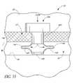
- the implantalso preferably comprises a scleral anchor extending from the outlet portion. The scleral anchor is configured to penetrate partially the sclera of the eye when the implant is positioned in the eye such that aqueous humor flows from the anterior chamber into the inlet portion, then into the outlet portion, and then into Schlemm's canal.
- the implantmay further comprise a stop that limits penetration of the implant through the sclera.
- the stopmay comprise a base of said outlet portion, an interface between the outlet portion and the scleral anchor, or at least one portion of said scleral anchor configured to radially extend into the sclera.
- Other means for limiting penetration of the implant through the scleramay also be used.
- the implantcomprises a solid-walled tube having at least two ends.
- the tubemay have multiple openings along a wall of said tube, the openings being spaced apart from the two ends.
- the tubemay have a cross-sectional shape selected from the group consisting of a circle, an ellipse, a rectangle, a square, and a polygon. Other shapes may also be used.
- the scleral anchormay comprise a screw configured to penetrate partially the sclera.
- the scleral anchormay comprise a sharp end, a conical shape, a screw, at least one protrusion, or a circumferential indentation.
- an implant for treating glaucomacomprising an inlet portion that is configured to be positioned in the anterior chamber of an eye and an outlet portion in fluid communication with the inlet portion.
- the outlet portionis preferably configured to be positioned at least partially in Schlemm's canal of the eye.
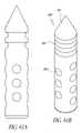
- the outlet portioncomprises a bulbous portion having at least two outlet openings along a surface of said bulbous potion, and the outlet openings are in fluid communication with the outlet and inlet portions.
- the surface of the bulbous portionis polyhedral.
- the bulbous portionhas a shape that comprises at least part of a sphere or at least part of an ellipsoid.
- the bulbous portionis substantially hemispherical in shape.
- FIG. 1is a coronal cross-sectional view of an eye
- FIG. 2is an enlarged cross-sectional view of an anterior chamber angle of the eye of FIG. 1 with a trabecular stent;
- FIG. 3is a schematic and partial sectional view of an eye illustrating an implanted glaucoma stent in accordance with one embodiment of at least one of the inventions disclosed herein;
- FIG. 4is a side elevational view of the stent of FIG. 3 ;
- FIG. 5is a top plan view of the stent of FIG. 3 ;
- FIG. 6is a bottom plan view of the stent of FIG. 3 ;
- FIG. 7is a front elevational view of the stent of FIG. 3 (along line 7 - 7 of FIG. 4 );
- FIG. 8is a rear elevational view of the stent of FIG. 3 (along line 8 - 8 of FIG. 4 );
- FIG. 9is an enlarged top plan view of a forward end of the stent of FIG. 3 ;
- FIG. 10is a top plan view of a modification of an inlet end of the stent of FIG. 3 ;
- FIG. 11is a top plan view of another modification of the inlet end of the stent of FIG. 3 ;
- FIG. 12is a top plan view of yet another modification of the inlet end of the stent of FIG. 3 ;
- FIG. 13is a top plan view of still another modification of the inlet end of the stent of FIG. 3 ;
- FIG. 14is schematic and partial sectional view of an eye illustrating a modification of the implanted glaucoma stent of FIG. 3 ;
- FIG. 15is a schematic and partial sectional view of an eye illustrating a further modification of the implanted glaucoma stent of FIG. 3 ;
- FIG. 16is a side elevational view of yet another modification of the glaucoma stent of FIG. 3 ;
- FIG. 17is a top plan view of the stent of FIG. 16 ;
- FIG. 18is a bottom plan view of the stent of FIG. 16 ;
- FIG. 19is a front elevational view along line 19 - 19 of FIG. 16 ;
- FIG. 20is a rear elevational view along line 20 - 20 of FIG. 16 ;
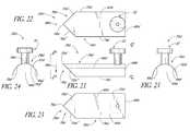
- FIG. 21is a side elevation view of still another modification of the glaucoma stent of FIG. 3 ;
- FIG. 22is a top plan view of the stent of FIG. 21 ;
- FIG. 23is a bottom plan view of the stent of FIG. 21 ;
- FIG. 24is a front elevational view along line 24 - 24 of FIG. 21 ;
- FIG. 25is a rear elevational view along line 25 - 25 of FIG. 21 ;
- FIG. 26is a front elevational view of a modification of the glaucoma stent illustrated in FIG. 3 ;
- FIG. 27is a right side elevational view of the stents illustrated in FIG. 26 as viewed along the line 27 - 27 ;
- FIG. 28is a right side elevational view of the glaucoma stent illustrated in FIG. 26 , as viewed along the line 28 - 28 ;
- FIG. 29is a schematic and partial sectional view of an eye illustrating a temporal implantation of a glaucoma stent using a delivery apparatus having features and advantages in accordance with at least one of the inventions disclosed herein;
- FIG. 30is an oblique elevational view of an articulating arm stent delivery/retrieval apparatus having features and advantages in accordance with an embodiment of at least one of the inventions disclosed herein;
- FIG. 31is a schematic and partial sectional view of a portion of an eye and illustrating an implantation of a glaucoma stent using a delivery apparatus extending through the anterior chamber of the eye;
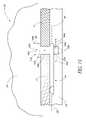
- FIG. 32is a schematic and partial sectional view of a Schlemm's canal and trabecular meshwork of an eye with another glaucoma stent extending from the anterior chamber of the eye, through the trabecular meshwork, and into a rear wall of the Schlemm's canal;
- FIG. 33is an enlarged cross-sectional view of a distal portion of the stent illustrated in FIG. 32 ;
- FIG. 34is a schematic and partial sectional view of the eye of FIG. 32 and a side elevational view of a modification of the stent illustrated in FIG. 32 ;
- FIG. 35is a schematic and partial sectional view of the eye illustrated in FIG. 32 , and a side elevational view of a photomodification of the stent illustrated in FIG. 32 ;
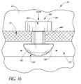
- FIG. 36is a schematic and partial sectional view of the eye illustrated in FIG. 32 , and a side elevational view of another modification of the stent of FIG. 32 ;
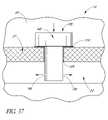
- FIG. 37is a schematic and partial sectional view of the eye illustrated in FIG. 32 , and a side elevational view of a further modification of the implant illustrated in FIG. 32 ;
- FIG. 38is a schematic and partial sectional view of the eye illustrated in FIG. 32 and a side elevational view of another modification of the stent illustrated in FIG. 32 ;
- FIG. 39is a schematic and partial sectional view of the eye illustrated in FIG. 32 , and a side elevational view of the further modification of the implant illustrated in FIG. 32 ;
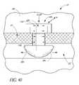
- FIG. 40is a schematic and partial sectional view of the eye illustrated in FIG. 32 , and a side elevational view of yet another modification of the stent illustrated in FIG. 32 ;
- FIG. 41is a schematic and partial sectional view of an eye and the side elevational view of yet another modification of the stent illustrated in FIG. 32 ;
- FIG. 42is a schematic and partial sectional view of the eye illustrated in FIG. 32 , and a side elevational view of yet another modification of the implant illustrated in FIG. 32 ;
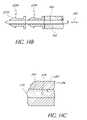
- FIG. 43is an enlarged schematic and partial cross-sectional view of an anterior chamber angle of an eye having a valve stent implanted therein;
- FIG. 44is an enlarged cross-sectional view of an anterior chamber angle of an eye including an osmotic membrane device implanted therein;
- FIG. 45is an enlarged cross-sectional view of an anterior chamber angle of an eye illustrating an implantation of a glaucoma stent using an ab externo procedure;
- FIG. 46is a schematic and partial sectional view of the eye illustrated in FIG. 32 and a side elevational view of another modification of the implant illustrated in FIG. 32 ;
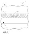
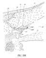
- FIG. 47is an enlarged schematic and partial sectional view of the eye illustrated in FIG. 32 and including a drug release device implanted therein;
- FIG. 48is a flow diagram illustrating a method for treating glaucoma
- FIG. 49Ais an enlarged schematic illustration showing an anterior chamber, trabecular meshwork and a Schlemm's canal of an eye and an oblique elevational view of yet another modification of the stent illustrated in FIG. 32 ;
- FIG. 49Bis an oblique elevational view of a modification of the stent illustrated in FIG. 49A ;
- FIG. 49Cis a side elevational view of another modification of the stent illustrated in FIG. 49A ;
- FIG. 50Ais a cross-sectional view of the eye portion showing anatomically the trabecular meshwork, Schlemm's canal and one collector duct;
- FIG. 50Bis a cross-sectional view of FIG. 50A with a portion of a stent mechanically inserted into one of the collector ducts;
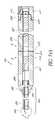
- FIG. 51Ais a side elevational view of a stent delivery applicator with a steerable distal section for multiple stent deployment;
- FIG. 51Bis a schematic and partial sectional view of the distal section of the stent delivery applicator of FIG. 51A ;
- FIG. 51Cis a cross-sectional view, section 1 - 1 of FIG. 51B ;
- FIG. 51Dis an oblique side elevational view of the steerable section of the delivery applicator illustrated in FIG. 51A and including an optional ultrasonically enabled distal end;
- FIG. 52Ais a partial sectional and side elevational view of a distal section of a modification of the stent delivery applicator illustrated in FIG. 51A ;
- FIG. 52Bis a partial sectional and side elevational view of a distal section of the stent delivery applicator illustrated in FIG. 51A having been inserted through a trabecular meshwork with the stent disposed within the distal section;
- FIG. 52Cis a partial sectional and side elevational view of a distal section of the stent delivery applicator illustrated in FIG. 51A having been inserted through a trabecular meshwork and after the sheath of the distal portion has been withdrawn;
- FIG. 52Dis a partial sectional and side elevational view of a distal section of the stent delivery applicator illustrated in FIG. 51A having been inserted through a trabecular meshwork, and after the sheath and a cutting member have been withdrawn;
- FIG. 53is an oblique side elevational and partial sectional view of a further modification of the stent illustrated in FIG. 32 ;
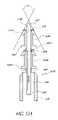
- FIG. 54Ais a sectional view of yet another modification of the stent delivery applicator illustrated in FIG. 51A ;
- FIG. 54Bis an enlarged sectional view of a distal end of the applicator illustrated in FIG. 54A and including two implants disposed over a trocar of the device, this portion being identified by the circle 2 - 2 in FIG. 54A ;
- FIG. 54Cis a sectional view of the applicator device taken along section line 3 - 3 of FIG. 54A ;
- FIGS. 55 A-Cshow multiple views of an embodiment of a trabecular stent.
- FIGS. 56 A-Bshow multiple views of another embodiment of a trabecular stent
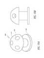
- FIGS. 57 A-Bshow multiple views of a trabecular stent having a modified center bulb with anchors
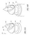
- FIGS. 58 A-Bshow multiple views of another embodiment of a trabecular stent
- FIGS. 59 A-Cshow multiple views of another embodiment of a trabecular stent
- FIGS. 60 A-Bshow multiple views of another embodiment of a trabecular stent with scleral anchors
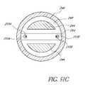
- FIGS. 61 A-Bshow multiple views of another embodiment of a trabecular stent with scleral anchors
- FIGS. 62 A-Bshow multiple views of a trabecular stent with screws
- FIGS. 63 A-Bshow multiple views of another embodiment of a trabecular stent
- FIGS. 64 A-Bshow a dual blade mushroom stent and its associated trocar delivery system
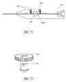
- FIG. 65shows a perspective view of a G 2 injector
- FIG. 66shows a top view of the G 2 injector of FIG. 65 ;
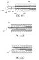
- FIG. 67shows a side cross-sectional view of a G 2 injector stem, showing solid trocar portion
- FIGS. 68 A-Cshow three modes of a side cross-sectional view of a G 2 injector stem, showing irrigating trocar portion;
- FIG. 69shows two modes of the G 2 injector (A) in the cocked orientation; (B) in the deployed orientation;
- FIGS. 70 A and Bshow two pusher tube locations of the button geometry
- FIG. 71shows a schematic of effective shorting of a pusher tube in the G 2 injector.
- FIG. 72illustrates where the pusher-tube resides when the G 2 injector is cocked.
- the preferred embodiments described hereinrelate particularly to surgical and therapeutic treatment of glaucoma through reduction of intraocular pressure and/or stimulation of the trabecular meshwork tissue. While the description sets forth various embodiment-specific details, it will be appreciated that the description is illustrative only and should not be construed in any way as limiting the inventions disclosed herein. Furthermore, various applications of the inventions disclosed herein, and modifications thereto, which may occur to those who are skilled in the art, are also encompassed by the general concepts described herein.
- FIG. 1is a cross-sectional view of an eye 10 .
- FIG. 2is an enlarged sectional view of the eye showing the relative anatomical locations of a trabecular meshwork 21 , an anterior chamber 20 , and a Schlemm's canal 22 .
- a sclera 11is a thick collagenous tissue which covers the entire eye 10 except a portion which is covered by a cornea 12 .
- the cornea 12is a thin transparent tissue that focuses and transmits light into the eye and through a pupil 14 , which is a circular hole in the center of an iris 13 (colored portion of the eye).
- the cornea 12merges into the sclera 11 at a juncture referred to as a limbus 15 .
- a ciliary body 16extends along the interior of the sclera 11 and is coextensive with a choroid 17 .
- the choroid 17is a vascular layer of the eye 10 , located between the sclera 11 and a retina 18 .
- An optic nerve 19transmits visual information to the brain and is the anatomic structure that is progressively destroyed by glaucoma.
- the anterior chamber 20 of the eye 10which is bound anteriorly by the cornea 12 and posteriorly by the iris 13 and a lens 26 , is filled with aqueous humor (hereinafter referred to as “aqueous”).
- aqueousaqueous humor
- Aqueousis produced primarily by the ciliary body 16 , then moves anteriorly through the pupil 14 and reaches an anterior chamber angle 25 , formed between the iris 13 and the cornea 12 .
- aqueousis removed from the anterior chamber 20 through the trabecular meshwork 21 .
- Aqueouspasses through the trabecular meshwork 21 into Schlemm's canal 22 and thereafter through a plurality of collector ducts and aqueous veins 23 , which merge with blood-carrying veins, and into systemic venous circulation.
- Intraocular pressureis maintained by an intricate balance between secretion and outflow of aqueous in the manner described above.
- Glaucomais, in most cases, characterized by an excessive buildup of aqueous in the anterior chamber 20 which leads to an increase in intraocular pressure. Fluids are relatively incompressible, and thus intraocular pressure is distributed relatively uniformly throughout the eye 10 .
- the trabecular meshwork 21is adjacent a small portion of the sclera 11 . Exterior to the sclera 11 is a conjunctiva 24 .
- Traditional procedures that create a hole or opening for implanting a device through the tissues of the conjunctiva 24 and sclera 11involve extensive surgery, as compared to surgery for implanting a device, as described herein, which ultimately resides entirely within the confines of the sclera 11 and cornea 12 .
- a trabecular stent 229can be placed bypassing the trabecular meshwork 21 with a proximal terminal 227 exposed to anterior chamber 20 and a distal terminal 228 exposed to Schlemm's canal 22 .
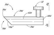
- FIG. 3schematically illustrates the use of one embodiment of a trabecular stenting device 30 for establishing an outflow pathway, passing through the trabecular meshwork 21 , described in greater detail below.
- FIGS. 4-9are different views of the stent 30 .
- a self-trephining stentallows a one-step procedure to make an incision in the trabecular mesh 21 and place the stent or implant 30 at the desired or predetermined position within the eye 10 . Desirably, this facilitates and simplifies the overall surgical procedure.
- the shunt or stent 30generally comprises an inlet portion or “snorkel” 32 and a main body portion or blade 34 .
- the snorkel 32 and blade 34are mechanically connected to or in mechanical communication with one another.
- a generally longitudinal axis 36extends along the stent 30 and/or the body portion 34 .
- the stent 30comprises an integral unit.
- the stent 30may comprise an assembly of individual pieces or components.
- the stent 30may comprise an assembly of the snorkel 32 and blade 34 .
- the snorkel 32is in the form of a generally elongate tubular member and generally comprises an upper seat, head or cap portion 38 , a shank portion 40 and a lumen or passage 42 extending therethrough.
- the seat 38is mechanically connected to or in mechanical communication with the shank 40 which is also mechanically connected to or in mechanical communication with the blade 34 .
- Longitudinal axis 43extends along the snorkel 32 and/or the lumen 42 .
- the seat 38is generally circular in shape and has an upper surface 44 and a lower surface 46 which, as shown in FIG. 3 , abuts or rests against the trabecular meshwork 21 to stabilize the glaucoma stent 30 within the eye 10 .
- the seat 38may efficaciously be shaped in other suitable manners, as required or desired, giving due consideration to the goals of stabilizing the glaucoma stent 30 within the eye 10 and/or of achieving one or more of the benefits and advantages as taught or suggested herein.
- the seat 38may be shaped in other polygonal or non-polygonal shapes and/or comprise one or more ridges which extend radially outwards, among other suitable retention devices.
- the seat top surface 44comprises fiducial marks or indicia 48 .
- These marks or indicia 48facilitate and ensure proper orientation and alignment of the stent 30 when implanted in the eye 10 .
- the marks or indicia 48may comprise visual differentiation means such as color contrast or be in the form of ribs, grooves, or the like.
- the marks 48may provide tactile sensory feedback to the surgeon by incorporating a radiopaque detectable or ultrasound imaginable substrate at about the mark 48 .
- the seat 38 and/or the seat top surface 44may be configured in predetermined shapes aligned with the blade 34 and/or longitudinal axis 36 to provide for proper orientation of the stent device 30 within the eye 10 .
- the seat top surface 44may be oval or ellipsoidal ( FIG. 10 ), rectangular ( FIG. 11 ), hexagonal ( FIG. 12 ), among other suitable shapes (e.g. FIG. 13 ).
- the seat bottom surface 46abuts or rests against the trabecular meshwork 21 to stabilize and retain the glaucoma stent 30 within the eye 10 .
- the seat bottom surface 46may comprise a stubbed surface, a ribbed surface, a surface with pillars, a textured surface, or the like.
- the snorkel shank 40is generally cylindrical in shape. With the stent 30 implanted, as shown in FIG. 3 , the shank 40 is generally positioned in an incision or cavity 50 formed in the trabecular meshwork 21 by the self-trephining stent 30 .
- this single step of forming the cavity 50 by the stent 30 itself and placing the stent 30 in the desired positionfacilitates and expedites the overall surgical procedure.
- the snorkel shank 40may efficaciously be shaped in other suitable manners, as required or desired.
- the shank 40may be in the shape of other polygonal or non-polygonal shapes, such as, oval, ellipsoidal, and the like.
- the shank 40has an outer surface 52 in contact with the trabecular meshwork 21 surrounding the cavity 50 .
- the shank outer surface 52may comprise a stubbed surface, a ribbed surface, a surface with pillars, a textured surface, or the like.
- the snorkel lumen 42has an inlet port, opening or orifice 54 at the seat top surface 44 and an outlet port, opening or orifice 56 at the junction of the shank 40 and blade 34 .
- the lumen 42is generally cylindrical in shape, that is, it has a generally circular cross-section, and its ports 54 , 56 are generally circular in shape.
- the lumen 42 and ports 54 , 56may be efficaciously shaped in other manners, as required or desired, giving due consideration to the goals of providing sufficient aqueous outflow and/or of achieving one or more of the benefits and advantages as taught or suggested herein.
- the lumen 42 and/or one or both ports 54 , 56may be shaped in the form of ovals, ellipsoids, and the like, or the lumen 42 may have a tapered or stepped configuration.
- aqueous from the anterior chamber 20flows into the lumen 42 through the inlet port 54 (as generally indicated by arrow 58 ) and out of the outlet port 56 and into Schlemm's canal 22 (as generally indicated by arrows 60 ) to lower and/or balance the intraocular pressure (IOP).
- IOPintraocular pressure
- one or more of the outlet portsmay be configured to face in the general direction of the stent longitudinal axis 36 .
- the snorkel 32may comprise more than one lumen, as needed or desired, to facilitate multiple aqueous outflow transportation into Schlemm's canal 22 .
- the blade longitudinal axis 36 and the snorkel longitudinal axis 43are generally perpendicular to one another. Stated differently, the projections of the axes 36 , 43 on a common plane which is not perpendicular to either of the axes 36 , 43 intersect at 90°.
- the blade longitudinal axis 36 and the snorkel longitudinal axis 43may intersect one another or may be offset from one another.
- the main body portion or blade 34is a generally curved elongated sheet- or plate-like structure with an upper curved surface 62 and a lower curved surface 64 which defines a trough or open face channel 66 .
- the perimeter of the blade 34is generally defined by a curved proximal edge 68 proximate to the snorkel 32 , a curved distal edge 70 spaced from the proximal edge 68 by a pair of generally straight lateral edges 72 , 74 .
- the first lateral edge 72extends beyond the second lateral edge 74 and intersects with the distal edge 70 at a distal-most point 76 of the blade 34 .
- the blade 34defines a blade cutting tip 78 .
- the cutting tip 78comprises a first cutting edge 80 on the distal edge 70 and a second cutting edge 82 on the lateral edge 72 .
- the cutting edges 80 , 82preferably extend from the distal-most point 76 of the blade 34 and comprise at least a respective portion of the distal edge 70 and lateral edge 72 .
- the respective cutting edges 80 , 82are formed at the sharp edges of respective beveled or tapered surfaces 84 , 86 . In one embodiment, the remainder of the distal edge 70 and lateral edge 72 are dull or rounded.
- the tip 78 proximate to the distal-most end 76is curved slightly inwards, as indicated generally by the arrow 88 in FIG. 5 and arrow 88 (pointed perpendicular and into the plane of the paper) in FIG. 9 , relative to the adjacent curvature of the blade 34 .
- suitable cutting edgesmay be provided on selected portions of one or more selected blade edges 68 , 70 , 72 , 74 with efficacy, as needed or desired, giving due consideration to the goals of providing suitable cutting means on the stent 30 for effectively cutting through the trabecular meshwork 21 ( FIG. 3 ) and/or of achieving one or more of the benefits and advantages as taught or suggested herein.
- the ratio between the lengths of the cutting edges 80 , 82is about 2:1. In another embodiment, the ratio between the lengths of the cutting edges 80 , 82 is about 1:1. In yet another embodiment, the ratio between the lengths of the cutting edges 80 , 82 is about 1:2. In modified embodiments, the lengths of the cutting edges 80 , 82 may be efficaciously selected in other manners, as required or desired, giving due consideration to the goals of providing suitable cutting means on the stent 30 for effectively cutting through the trabecular meshwork 21 ( FIG. 3 ) and/or of achieving one or more of the benefits and advantages as taught or suggested herein.
- the ratio between the lengths of the cutting edges 80 , 82is in the range from about 2:1 to about 1:2. In another embodiment, the ratio between the lengths of the cutting edges 80 , 82 is in the range from about 5:1 to about 1:5. In yet another embodiment, the ratio between the lengths of the cutting edges 80 , 82 is in the range from about 10:1 to about 1:10. In modified embodiments, the lengths of the cutting edges 80 , 82 may be efficaciously selected in other manners, as required or desired, giving due consideration to the goals of providing suitable cutting means on the stent 30 for effectively cutting through the trabecular meshwork 21 ( FIG. 3 ) and/or of achieving one or more of the benefits and advantages as taught or suggested herein.
- the cutting edge 80 (and/or the distal end 70 ) and the cutting edge 82 (and/or the lateral edge 72 )intersect at an angle ⁇ .
- ⁇is the angle between the projections of the cutting edge 80 (and/or the distal end 70 ) and the cutting edge 82 (and/or the lateral edge 72 ) on a common plane which is not perpendicular to either of these edges.
- the angle ⁇is about 50°. In another embodiment, the angle ⁇ is in the range from about 40° to about 60°. In yet another embodiment, the angle ⁇ is in the range from about 30° to about 70°. In modified embodiments, the angle ⁇ may be efficaciously selected in other manners, as required or desired, giving due consideration to the goals of providing suitable cutting means on the stent 30 for effectively cutting through the trabecular meshwork 21 ( FIG. 3 ) and/or of achieving one or more of the benefits and advantages as taught or suggested herein.
- the stent 30 of the embodiments disclosed hereincan be dimensioned in a wide variety of manners.
- the depth of Schlemm's canal 22is typically about less than 400 microns ( ⁇ m).
- the stunt blade 34is dimensioned so that the height of the blade 34 (referred to as H 41 in FIG. 4 ) is typically less than about 400 ⁇ m.
- the snorkel shank 40is dimensioned so that it has a length (referred to as L 41 in FIG. 4 ) typically in the range from about 150 ⁇ m to about 400 ⁇ m which is roughly the typical range of the thickness of the trabecular meshwork 21 .
- the blade 34may rest at any suitable position within Schlemm's canal 22 .
- the blade 34may be adjacent to a front wall 90 of Schlemm's canal 22 (as shown in FIG. 3 ), or adjacent to a back wall 92 of Schlemm's canal 22 , or at some intermediate location therebetween, as needed or desired.
- the snorkel shank 40may extend into Schlemm's canal 22 . The length of the snorkel shank 40 and/or the dimensions of the blade 34 may be efficaciously adjusted to achieve the desired implant positioning.
- the trabecular stenting device 30 ( FIGS. 3-9 ) of the exemplary embodimentmay be manufactured or fabricated by a wide variety of techniques. These include, without limitation, molding, thermo-forming, or other micro-machining techniques, among other suitable techniques.
- the trabecular stenting device 30preferably comprises a biocompatible material such that inflammation arising due to irritation between the outer surface of the device 30 and the surrounding tissue is minimized.
- Biocompatible materials which may be used for the device 30preferably include, but are not limited to, titanium, titanium alloys, medical grade silicone, e.g., SILASTICTM, available from Dow Corning Corporation of Midland, Mich.; and polyurethane, e.g., PELLETHANETM, also available from Dow Corning Corporation.
- the stent device 30may comprise other types of biocompatible material, such as, by way of example, polyvinyl alcohol, polyvinyl pyrolidone, collagen, heparinized collagen, polytetrafluoroethylene, expanded polytetrafluoroethylene, fluorinated polymer, fluorinated elastomer, flexible fused silica, polyolefin, polyester, polysilicon, and/or a mixture of the aforementioned biocompatible materials, and the like.
- composite biocompatible materialmay be used, wherein a surface material may be used in addition to one or more of the aforementioned materials.
- such a surface materialmay include polytetrafluoroethylene (PTFE) (such as TEFLONTM), polyimide, hydrogel, heparin, therapeutic drugs (such as beta-adrenergic antagonists and other anti-glaucoma drugs, or antibiotics), and the like.
- PTFEpolytetrafluoroethylene
- TEFLONTMpolytetrafluoroethylene
- polyimidesuch as TEFLONTM
- hydrogelsuch as heparin
- therapeutic drugssuch as beta-adrenergic antagonists and other anti-glaucoma drugs, or antibiotics
- the patientis placed in the supine position, prepped, draped and anesthetized as necessary.
- a small (less than about 1 mm) incisionwhich may be self sealing can then be made through the cornea 12 .
- the corneal incisioncan be made in a number of ways, for example, by using a micro-knife, among other tools.
- An applicator or delivery apparatusis used to advance the glaucoma stent 30 through the corneal incision and to the trabecular meshwork 21 .
- Some embodiments of such a delivery apparatusare disclosed in U.S. application Ser. No. 10/101,548, filed Mar. 18, 2002, entitled APPLICATOR AND METHODS FOR PLACING A TRABECULAR SHUNT FOR GLAUCOMA TREATMENT, and U.S. Provisional Application No. 60/276,609, filed Mar. 16, 2001, entitled APPLICATOR AND METHODS FOR PLACING A TRABECULAR SHUNT FOR GLAUCOMA TREATMENT, the entire contents of each one of which are hereby incorporated by reference herein.
- Some embodiments of a delivery apparatusare also described in further detail below. Gonioscopic, microscopic, or endoscopic guidance can be used during the trabecular meshwork surgery.
- the blade 34 of the device 30is used to cut and/or displace the material of the trabecular meshwork 21 .
- the snorkel shank 40can also facilitate in removal of this material during implantation.
- the delivery apparatusis withdrawn once the device 30 has been implanted in the eye 10 .
- the snorkel seat 38can rest on a top surface 94 of the trabecular meshwork 21 with the snorkel shank 40 extending through the cavity 50 (created by the device 30 ) in the trabecular meshwork 21 , and with the blade 34 extending inside Schlemm's canal 22 .
- the embodiments of the self-trephining stent device 30allow for a “one-step” procedure to make an incision in the trabecular meshwork and to implant the stent in the proper orientation and alignment within the eye to allow outflow of aqueous from the anterior chamber through the stent and into Schlemm's canal to lower and/or balance the intraocular pressure (IOP). Desirably, this provides for a faster, safer, and less expensive surgical procedure.
- IOPintraocular pressure
- trabecular meshwork surgerieswherein a knife is first used to create an incision in the trabecular meshwork, followed by removal of the knife and subsequent installation of the stent.
- the knifemay cause some bleeding which clouds up the surgical site. This may require more effort and time to clean the surgical site prior to placement of the stent.
- thismay cause the intraocular pressure (IOP) to rise or to fall undesirably.
- IOPintraocular pressure
- such a multiple step proceduremay demand crisis management which slows down the surgery, makes it less safe, and more expensive.
- FIG. 14is a simplified partial view of an eye 10 illustrating the implantation of a self-trephining glaucoma stent device 30 a having features and advantages in accordance with one embodiment.
- the stent 30 ais generally similar to the stent 30 of FIGS. 3-9 except that its snorkel 32 a comprises a longer shank 40 a which extends into Schlemm's canal 22 and a lumen 42 a which bifurcates into two output channels 45 a.
- the shank 40 aterminates at the blade 34 .
- Aqueousflows from the anterior chamber 20 into the lumen 42 a through an inlet port 54 a (as generally indicated by arrow 58 a ).
- Aqueousthen flows through the output channels 45 a and out of respective outlet ports 56 a and into Schlemm's canal 22 (as generally indicated by arrows 60 a ).
- the outlet channels 45 aextend radially outwards in generally opposed directions and the outlet ports 56 a are configured to face in the general direction of the stent longitudinal axis 36 so that they open into Schlemm's canal 22 and are in proper orientation to allow aqueous outflow into Schlemm's canal 22 for lowering and/or balancing the intraocular pressure (IOP).
- IOPintraocular pressure
- fiducial marks or indicia and/or predetermined shapes of the snorkel seat 38allow for proper orientation of the blade 34 and also the output channels 45 a and respective ports 56 a within Schlemm's canal.
- two outflow channels 45 aare provided. In another embodiment, only one outflow channel 45 a is provided. In yet another embodiment, more than two outflow channels 45 a are provided. In modified embodiments, the lumen 42 a may extend all the way through to the blade 34 and provide an outlet port as discussed above with reference to the embodiment of FIGS. 3-9 .
- FIG. 15is a simplified partial view of an eye 10 illustrating the implantation of a self-trephining glaucoma stent device 30 b having features and advantages in accordance with one embodiment.
- the stent 30 bis generally similar to the stent 30 of FIGS. 3-9 except that its snorkel 32 b comprises a longer shank 40 b which extends into Schlemm's canal 22 and a lumen 42 b which bifurcates into two output channels 45 b.
- the shank 40 bextends through the blade 34 .
- Aqueousflows from the anterior chamber 20 into the lumen 42 b through an inlet port 54 b (as generally indicated by arrow 58 b ).
- Aqueousthen flows through the output channels 45 b and out of respective outlet ports 56 b and into Schlemm's canal 22 (as generally indicated by arrows 60 b ).
- the outlet channels 45 bextend radially outwards in generally opposed directions and the outlet ports 56 b are configured to face in the general direction of the stent longitudinal axis 36 so that they open into Schlemm's canal 22 and are in proper orientation to allow aqueous outflow into Schlemm's canal 22 for lowering and/or balancing the intraocular pressure (IOP).
- IOPintraocular pressure
- fiducial marks or indicia and/or predetermined shapes of the snorkel seat 38allow for proper orientation of the blade 34 and also the output channels 45 b and respective ports 56 b within Schlemm's canal.
- two outflow channels 45 bare provided. In another embodiment, only one outflow channel 45 b is provided. In yet another embodiment, more than two outflow channels 45 b are provided. In modified embodiments, the lumen 42 b may extend all the way through to the blade 34 and provide an outlet port as discussed above with reference to the embodiment of FIGS. 3-9 .
- FIGS. 16-20show different views of a self-trephining glaucoma stent device 30 c having features and advantages in accordance with one embodiment.
- the stent 30 cis generally similar to the stent 30 of FIGS. 3-9 except that it has a modified blade configuration.
- the stent 30 ccomprises a blade 34 c which is a generally curved elongated sheet- or plate-like structure with an upper curved surface 62 c and a lower curved surface 64 c which defines a trough or open face channel 66 c .
- the perimeter of the blade 34 cis generally defined by a curved proximal edge 68 c proximate to the snorkel 32 , a curved distal edge 70 c spaced from the proximal edge 68 c by a pair of generally straight lateral edges 72 c , 74 c which are generally parallel to one another and have about the same length.
- the blade 34 ccomprises a cutting tip 78 c .
- the cutting tip 78 cpreferably includes cutting edges formed on selected portions of the distal edge 70 c and adjacent portions of the lateral edges 72 c , 74 c for cutting through the trabecular meshwork for placement of the snorkel 32 .
- the cutting edgesare sharp edges of beveled or tapered surfaces as discussed above in reference to FIG. 9 .
- the embodiment of FIGS. 16-20may be efficaciously modified to incorporate the snorkel configuration of the embodiments of FIGS. 14 and 15 .
- FIGS. 21-25show different views of a self-trephining glaucoma stent device 30 d having features and advantages in accordance with one embodiment.
- the stent 30 dis generally similar to the stent 30 of FIGS. 3-9 except that it has a modified blade configuration.
- the stent 30 dcomprises a blade 34 d which is a generally curved elongated sheet- or plate-like structure with an upper curved surface 62 d and a lower curved surface 64 d which defines a trough or open face channel 66 d .
- the perimeter of the blade 34 dis generally defined by a curved proximal edge 68 d proximate to the snorkel 32 , a pair of inwardly converging curved distal edges 70 d ′, 70 d ′′ spaced from the proximal edge 68 d by a pair of generally straight respective lateral edges 72 d , 74 d which are generally parallel to one another and have about the same length.
- the distal edges 70 d ′, 70 d ′′intersect at a distal-most point 76 d of the blade 34 d proximate a blade cutting tip 78 d.
- the cutting tip 78 dpreferably includes cutting edges formed on the distal edges 70 d ′, 70 d ′′ and extending from the distal-most point 76 d of the blade 34 d .
- the cutting edgesextend along only a portion of respective distal edges 70 d ′, 70 d .′′
- the cutting edgesextend along substantially the entire length of respective distal edges 70 d ′, 70 d .′′
- at least portions of the lateral edges 72 d , 74 d proximate to respective distal edges 70 d ′, 70 d ′′have cutting edges.
- the tip 78 d proximate to the distal-most end 76 dis curved slightly inwards, as indicated generally by the arrow 88 d in FIG. 21 and arrow 88 d (pointed perpendicular and into the plane of the paper) in FIG. 22 , relative to the adjacent curvature of the blade 34 d.
- the cutting edgesare sharp edges of beveled or tapered surfaces as discussed above in reference to FIG. 9 .
- the embodiment of FIGS. 21-25may be efficaciously modified to incorporate the snorkel configuration of the embodiments of FIGS. 14 and 15 .
- FIGS. 26-28show different views of a self-trephining glaucoma stent device 30 e having features and advantages in accordance with one embodiment.
- the stent device 30 egenerally comprises a snorkel 32 e mechanically connected to or in mechanical communication with a blade or cutting tip 34 e .
- the snorkel 32 ehas a seat, head or cap portion 38 e mechanically connected to or in mechanical communication with a shank 40 e , as discussed above.
- the shank 40 ehas a distal end or base 47 e .
- the snorkel 32 efurther has a lumen 42 e which bifurcates into a pair of outlet channels 45 e , as discussed above in connection with FIGS. 14 and 15 .
- Other lumen and inlet and outlet port configurations as taught or suggested hereinmay also be efficaciously used, as needed or desired.
- the blade 34 eextends downwardly and outwardly from the shank distal end 47 e .
- the blade 34 eis angled relative to a generally longitudinal axis 43 e of the snorkel 32 e , as best seen in FIGS. 27 and 28 .
- the blade 34 ehas a distal-most point 76 e .
- the blade or cutting tip 34 ehas a pair of side edges 70 e ′, 70 e ,′′ including cutting edges, terminating at the distal-most point 76 e , as best seen in FIG. 26 .
- the cutting edgesare sharp edges of beveled or tapered surfaces as discussed above in reference to FIG. 9 .
- the blade 34 eincludes cutting edges formed on the edges 70 e ′, 70 e ′′ and extending from the distal-most point 76 e of the blade 34 d .
- the cutting edgesextend along only a portion of respective distal edges 70 e ′, 70 e .′′
- the cutting edgesextend along substantially the entire length of respective distal edges 70 e ′, 70 e .′′
- the blade or cutting tip 34 ecomprises a bent tip of needle, for example, a 30 gauge needle.
- any of the blade configurations disclosed hereinmay be used in conjunction with any of the snorkel configurations disclosed herein or incorporated by reference herein to provide a self-trephining glaucoma stent device for making an incision in the trabecular meshwork for receiving the corresponding snorkel to provide a pathway for aqueous outflow from the eye anterior chamber to Schlemm's canal, thereby effectively lowering and/or balancing the intraocular pressure (IOP).
- IOPintraocular pressure
- the self-trephining ability of the deviceadvantageously, allows for a “one-step” procedure in which the incision and placement of the snorkel are accomplished by a single device and operation.
- fiducial markings or indicia, and/or preselected configuration of the snorkel seat, and/or positioning of the stent device in a preloaded applicatormay be used for proper orientation and alignment of the device during implantation.
- FIG. 29illustrates a temporal implant procedure, wherein a delivery apparatus or “applicator” 100 having a curved tip 102 is used to deliver a stent 30 to a temporal side 27 of the eye 10 .
- An incision 28is made in the cornea 10 , as discussed above.
- the apparatus 100is then used to introduce the stent 30 through the incision 28 and implant it within the eye 10 .
- a similarly curved instrumentwould be used to make the incision through the trabecular meshwork 21 .
- a self-trephining stent device 30may be used to make this incision through the trabecular meshwork 21 , as discussed above.
- the temporal implantation procedure illustrated in FIG. 29may be employed with the any of the various stent embodiments taught or suggested herein.
- FIG. 30illustrates one embodiment of an apparatus comprising an articulating stent applicator or retrieval device 100 a .
- a proximal arm 106is attached to a distal arm 108 at a joint 112 .
- This joint 112is movable such that an angle formed between the proximal arm 106 and the distal arm 108 can change.
- One or more claws 114can extend from the distal arm 108 , in the case of a stent retrieval device.
- this articulation mechanismmay be used for the trabecular stent applicator, and thus the articulating applicator or retrieval device 100 a may be either an applicator for the trabecular stent, a retrieval device, or both, in various embodiments.
- the embodiment of FIG. 30may be employed with the any of the various stent embodiments taught or suggested herein.
- FIG. 31shows another illustrative method for placing any of the various stent embodiments taught or suggested herein at the implant site within the eye 10 .
- a delivery apparatus 100 bgenerally comprises a syringe portion 116 and a cannula portion 118 .
- the distal section of the cannula 118has at least one irrigating hole 120 and a distal space 122 for holding the stent device 30 .
- the proximal end 124 of the lumen of the distal space 122is sealed from the remaining lumen of the cannula portion 118 .
- the delivery apparatus of FIG. 30may be employed with the any of the various stent embodiments taught or suggested herein.
- a delivery apparatus(or “applicator”) is used for placing a trabecular stent through a trabecular meshwork of an eye.
- a delivery apparatusor “applicator”
- Certain embodiments of such a delivery apparatusare disclosed in U.S. application Ser. No. 10/101,548, filed Mar. 18, 2002, entitled APPLICATOR AND METHODS FOR PLACING A TRABECULAR SHUNT FOR GLAUCOMA TREATMENT, and U.S. Provisional Application No. 60/276,609, filed Mar. 16, 2001, entitled APPLICATOR AND METHODS FOR PLACING A TRABECULAR SHUNT FOR GLAUCOMA TREATMENT.
- the stenthas an inlet section and an outlet section.
- the delivery apparatusincludes a handpiece, an elongate tip, a holder and an actuator.
- the handpiecehas a distal end and a proximal end.
- the elongate tipis connected to the distal end of the handpiece.
- the elongate tiphas a distal portion and is configured to be placed through a corneal incision and into an anterior chamber of the eye.
- the holderis attached to the distal portion of the elongate tip.
- the holderis configured to hold and release the inlet section of the trabecular stent.
- the actuatoris on the handpiece and actuates the holder to release the inlet section of the trabecular stent from the holder.
- the outlet sectionis positioned in substantially opposite directions inside Schlemm's canal.
- a deployment mechanism within the delivery apparatusincludes a push-pull type plunger.
- the holdercomprises a clamp.
- the apparatusfurther comprises a spring within the handpiece that is configured to be loaded when the stent is being held by the holder, the spring being at least partially unloaded upon actuating the actuator, allowing for release of the stent from the holder.
- the clampcomprises a plurality of claws configured to exert a clamping force onto the inlet section of the stent.
- the holdermay also comprise a plurality of flanges.
- the distal portion of the elongate tipis made of a flexible material. This can be a flexible wire.
- the distal portioncan have a deflection range, preferably of about 45 degrees from the long axis of the handpiece.
- the delivery apparatuscan further comprise an irrigation port in the elongate tip.
- Some embodimentsinclude a method of placing a trabecular stent through a trabecular meshwork of an eye, the stent having an inlet section and an outlet section, including advancing a delivery apparatus holding the trabecular stent through an anterior chamber of the eye and into the trabecular meshwork, placing part of the stent through the trabecular meshwork and into a Schlemm's canal of the eye; and releasing the stent from the delivery apparatus.
- the methodincludes using a delivery apparatus that comprises a handpiece having a distal end and a proximal end and an elongate tip connected to the distal end of the handpiece.
- the elongate tiphas a distal portion and being configured to be placed through a corneal incision and into an anterior chamber of the eye.
- the apparatusfurther has a holder attached to the distal portion of the elongate tip, the holder being configured to hold and release the inlet section of the trabecular stent, and an actuator on the handpiece that actuates the holder to release the inlet section of the trabecular stent from the holder.
- the trabecular stentis removably attached to a delivery apparatus (also known as “applicator”).
- a delivery apparatusalso known as “applicator”.
- the outlet sectionis positioned in substantially opposite directions inside Schlemm's canal.
- a deployment mechanism within the delivery apparatusincludes a push-pull type plunger.
- the delivery applicatormay be a guidewire, an expandable basket, an inflatable balloon, or the like.
- FIGS. 32 and 33illustrate a glaucoma stent device 30 f having features and advantages in accordance with one embodiment.
- This embodiment of the trabecular stent 30 fincludes a barbed or threaded screw-like extension or pin 126 with barbs 128 for anchoring.
- the barbed pin 126extends from a distal or base portion 130 of the stent 30 f.
- the stent 30 f( FIG. 32 ) is advanced through the trabecular meshwork 21 and across Schlemm's canal 22 .
- the barbed (or threaded) extension 126penetrates into the back wall 92 of Schlemm's canal 22 up to the shoulder or base 130 that then rests on the back wall 92 of the canal 22 .
- the combination of a shoulder 130 and a barbed pin 126 of a particular lengthlimits the penetration depth of the barbed pin 126 to a predetermined or preselected distance. In one embodiment, the length of the pin 126 is about 0.5 mm or less.
- this barbed configurationprovides a secure anchoring of the stent 30 f . As discussed above, correct orientation of the stent 30 f is ensured by appropriate fiducial marks, indicia or the like and by positioning of the stent in a preloaded applicator.
- the aqueousflows from the anterior chamber 20 , through the lumen 42 f , then out through two side-ports 56 f to be directed in both directions along Schlemm's canal 22 .
- flowcould be directed in only one direction through a single side-port 56 f .
- more then two outlet ports 56 ffor example, six to eight ports (like a pin wheel configuration), may be efficaciously used, as needed or desired.
- the stent 30 fis inserted through a previously made incision in the trabecular meshwork 21 .
- the stent 30 fmay be combined with any of the blade configurations taught or suggested herein to provide self-trephining capability.
- the incision through the trabecular meshwork 21is made by the self-trephining stent device which has a blade at its base or proximate to the base.
- FIG. 34illustrates a glaucoma stent device 30 g having features and advantages in accordance with one embodiment.
- the stent 30 ghas a head or seat 38 g and a shank or main body portion 40 g with a base or distal end 132 .
- This embodiment of the trabecular stent 30 gincludes a deep thread 134 (with threads 136 ) on the main body 40 g of the stent 30 g below the head 38 g .
- the threadsmay or may not extend all the way to the base 132 .
- the stent 30 g( FIG. 34 ) is advanced through the meshwork 21 through a rotating motion, as with a conventional screw.
- the deep threads 136provide retention and stabilization of the stent 30 g in the trabecular meshwork 21 .
- the aqueousflows from the anterior chamber 20 , through the lumen 42 g , then out through two side-ports 56 g to be directed in both directions along Schlemm's canal 22 .
- flowcould be directed in only one direction through a single side-port 56 g .
- more then two outlet ports 56 gmay be efficaciously used, as needed or desired.
- One suitable applicator or delivery apparatus for this stent 30 gincludes a preset rotation, for example, via a wound torsion spring or the like. The rotation is initiated by a release trigger on the applicator. A final twist of the applicator by the surgeon and observation of suitable fiducial marks, indicia or the like ensure proper alignment of the side ports 56 g with Schlemm's canal 22 .
- the stent 30 gis inserted through a previously made incision in the trabecular meshwork 21 .
- the stent 30 gmay be combined with any of the blade configurations taught or suggested herein to provide self-trephining capability.
- the incision through the trabecular meshwork 21is made by the self-trephining stent device which has a blade at its base or proximate to the base.
- FIG. 35illustrates a glaucoma stent device 30 h having features and advantages in accordance with one embodiment.
- the stenthas a base or distal end 138 .
- This embodiment of the trabecular stent 30 hhas a pair of flexible ribs 140 . In the unused state, the ribs are initially generally straight (that is, extend in the general direction of arrow 142 ).
- the ends 144 of respective ribs 140 of the stent 30 hcome to rest on the back wall 92 of Schlemm's canal 22 . Further advancement of the stent 30 h causes the ribs 140 to deform to the bent shape as shown in the drawing of FIG. 35 .
- the ribs 140are designed to first buckle near the base 138 of the stent 30 h . Then the buckling point moves up the ribs 140 as the shank part 40 h of the stent 30 h is further advanced through the trabecular meshwork 21 .
- the lumen 42 h ( FIG. 35 ) in the stent 30 his a simple straight hole.
- the aqueousflows from the anterior chamber 20 , through the lumen 42 h , then out around the ribs 140 to the collector channels further along Schlemm's canal 22 in either direction.
- the stent 30 his inserted through a previously made incision in the trabecular meshwork 21 .
- the stent 30 hmay be combined with any of the blade configurations taught or suggested herein to provide self-trephining capability.
- the incision through the trabecular meshwork 21is made by the self-trephining stent device which has a blade at its base or proximate to the base.
- FIG. 36illustrates a glaucoma stent device 30 i having features and advantages in accordance with one embodiment.
- This embodiment of the trabecular stent 30 iincludes a head or seat 38 i , a tapered base portion 146 and an intermediate narrower waist portion or shank 40 i.
- the stent 30 i( FIG. 36 ) is advanced through the trabecular meshwork 21 and the base 146 is pushed into Schlemm's canal 22 .
- the stent 30 iis pushed slightly further, if necessary, until the meshwork 21 stretched by the tapered base 146 relaxes back and then contracts to engage the smaller diameter portion waist 40 i of the stent 30 i .
- the combination of the larger diameter head or seat 38 i and base 146 of the stent 30 iconstrains undesirable stent movement.
- correct orientation of the stent 30 iis ensured by appropriate fiducial marks, indicia or the like and by positioning of the stent in a preloaded applicator.
- the aqueousflows from the anterior chamber 20 , through the lumen 42 i , then out through two side-ports 56 i to be directed in both directions along Schlemm's canal 22 .
- flowcould be directed in only one direction through a single side-port 56 i .
- more then two outlet ports 56 imay be efficaciously used, as needed or desired.
- the stent 30 iis inserted through a previously made incision in the trabecular meshwork 21 .
- the stent 30 imay be combined with any of the blade configurations taught or suggested herein to provide self-trephining capability.
- the incision through the trabecular meshwork 21is made by the self-trephining stent device which has a blade at its base or proximate to the base.
- FIG. 37illustrates a glaucoma stent device 30 j having features and advantages in accordance with one embodiment.
- This embodiment of the trabecular stent 30 jutilizes a region of biointeractive material 148 that provides a site for the trabecular meshwork 21 to firmly grip the stent 30 j by ingrowth of the tissue into the biointeractive material 148 .
- the biointeractive layer 148is applied to those surfaces of the stent 30 j which would abut against or come in contact with the trabecular meshwork 21 .
- the biointeractive layer 148may be a region of enhanced porosity with a growth promoting chemical.
- a type of bio-glue 150 that dissolves over timeis used to hold the stent secure during the time between insertion and sufficient ingrowth for stabilization. As discussed above, correct orientation of the stent 30 j is ensured by appropriate fiducial marks, indicia or the like and by positioning of the stent in a preloaded applicator.
- the aqueousflows from the anterior chamber 20 , through the lumen 42 j , then out through two side-ports 56 j to be directed in both directions along Schlemm's canal 22 .
- flowcould be directed in only one direction through a single side-port 56 j .
- more then two outlet ports 56 jmay be efficaciously used, as needed or desired.
- the stent 30 jis inserted through a previously made incision in the trabecular meshwork 21 .
- the stent 30 jmay be combined with any of the blade configurations taught or suggested herein to provide self-trephining capability.
- the incision through the trabecular meshwork 21is made by the self-trephining stent device which has a blade at its base or proximate to the base.
- FIG. 38illustrates a glaucoma stent device 30 k having features and advantages in accordance with one embodiment.
- This embodiment of the trabecular stent 30 kis secured in place by using a permanent (non-dissolving) bio-glue 152 or a “welding” process (e.g. heat) to form a weld 152 .
- the stent 30 khas a head or seat 38 k and a lower surface 46 k.
- the stent 30 kis advanced through the trabecular meshwork 21 until the head or seat 38 k comes to rest on the trabecular meshwork 21 , that is, the head lower surface 46 k abuts against the trabecular meshwork 21 , and the glue or weld 152 is applied or formed therebetween, as shown in FIG. 38 .
- correct orientation of the stent 30 kis ensured by appropriate fiducial marks, indicia or the like and by positioning of the stent in a preloaded applicator.
- the aqueousflows from the anterior chamber 20 , through the lumen 42 k , then out through two side-ports 56 k to be directed in both directions along Schlemm's canal 22 .
- flowcould be directed in only one direction through a single side-port 56 k .
- more then two outlet ports 56 kmay be efficaciously used, as needed or desired.
- the stent 30 kis inserted through a previously made incision in the trabecular meshwork 21 .
- the stent 30 kmay be combined with any of the blade configurations taught or suggested herein to provide self-trephining capability.
- the incision through the trabecular meshwork 21is made by the self-trephining stent device which has a blade at its base or proximate to the base.
- FIG. 39illustrates a glaucoma stent device 30 m having features and advantages in accordance with one embodiment.
- This embodiment of the trabecular stent 30 mis fabricated from a hydrophilic material that expands with absorption of water. Desirably, this would enable the device 30 m to be inserted through a smaller incision in the trabecular meshwork 21 .
- the subsequent expansion (illustrated by the smaller arrows 154 ) of the stent 30 mwould advantageously enable it to latch in place in the trabecular meshwork 21 .
- correct orientation of the stent 30 mis ensured by appropriate fiducial marks, indicia or the like and by positioning of the stent in a preloaded applicator.
- the aqueousflows from the anterior chamber 20 , through the lumen 42 m , then out through two side-ports 56 m to be directed in both directions along Schlemm's canal 22 .
- flowcould be directed in only one direction through a single side-port 56 m .
- more then two outlet ports 56 mmay be efficaciously used, as needed or desired.
- the stent 30 mis inserted through a previously made incision in the trabecular meshwork 21 .
- the stent 30 mmay be combined with any of the blade configurations taught or suggested herein to provide self-trephining capability.
- the incision through the trabecular meshwork 21is made by the self-trephining stent device which has a blade at its base or proximate to the base.
- FIG. 40illustrates a glaucoma stent device 30 n having features and advantages in accordance with one embodiment.
- This embodiment of the trabecular stent 30 nis fabricated from a photodynamic material that expands on exposure to light.
- the lumen 42 n of the stent 30 nresponds to light entering the cornea during the day by expanding and allowing higher flow of aqueous through the lumen 42 n and into Schlemm's canal 22 . This expansion is generally indicated by the smaller arrows 156 ( FIG. 40 ) which show the lumen 42 n (and ports) expanding or opening in response to light stimulus.
- Eh ⁇
- ⁇Planck's constant
- ⁇the frequency of the light provided.
- an excitation wavelength that is different from that commonly encounteredis provided on an as-needed basis to provide higher flow of aqueous to Schlemm's canal 22 .
- This photodynamic implementationis shown in FIG. 40 for the self-latching style of stent 30 n , but can be efficaciously used with any of the other stent embodiments, as needed or desired.
- correct orientation of the stent 30 nis ensured by appropriate fiducial marks, indicia or the like and by positioning of the stent in a preloaded applicator.
- the aqueousflows from the anterior chamber 20 , through the lumen 42 n , then out through two side-ports 56 n to be directed in both directions along Schlemm's canal 22 .
- flowcould be directed in only one direction through a single side-port 56 n .
- more then two outlet ports 56 nmay be efficaciously used, as needed or desired.
- the stent 30 nis inserted through a previously made incision in the trabecular meshwork 21 .
- the stent 30 nmay be combined with any of the blade configurations taught or suggested herein to provide self-trephining capability.
- the incision through the trabecular meshwork 21is made by the self-trephining stent device which has a blade at its base or proximate to the base.
- FIG. 41illustrates a glaucoma stent device 30 p having features and advantages in accordance with one embodiment.
- This figuredepicts an embodiment of a stent 30 p that directs aqueous from the anterior chamber 20 directly into a collector channel 29 which empties into aqueous veins.
- the stent 30 phas a base or distal end 160 .
- a removable alignment pin 158is utilized to align the stent lumen 42 p with the collector channel 29 .
- the pin 158extends through the stent lumen 42 p and protrudes through the base 160 and extends into the collector channel 29 to center and/or align the stent 30 p over the collector channel 29 .
- the stent 30 pis then pressed firmly against the back wall 92 of Schlemm's canal 22 .
- a permanent bio-glue 162is used between the stent base and the back wall 92 of Schlemm's canal 22 to seat and securely hold the stent 30 p in place.
- the pin 158is withdrawn from the lumen 42 p to allow the aqueous to flow directly from the anterior chamber 20 into the collector duct 29 .
- the collector ductsare nominally 20 to 100 micrometers ( ⁇ m) in diameter and are visualized with a suitable microscopy method (such as ultrasound biomicroscopy (UBM)) or laser imaging to provide guidance for placement of the stent 30 p.
- UBMultrasound biomicroscopy
- the stent 30 pis inserted through a previously made incision in the trabecular meshwork 21 .
- the stent 30 pmay be combined with any of the blade configurations taught or suggested herein to provide self-trephining capability.
- the incision through the trabecular meshwork 21is made by the self-trephining stent device which has a blade at its base or proximate to the base.
- FIG. 42illustrates a glaucoma stent device 30 q having features and advantages in accordance with one embodiment.
- This figuredepicts an embodiment of a stent 30 q that directs aqueous from the anterior chamber 20 directly into a collector channel 29 which empties into aqueous veins.
- the stent 30 qhas a base or distal end 166 and the channel 29 has wall(s) 164 .
- a barbed, small-diameter extension or pin 168 on the stent base 166is guided into the collector channel 29 and anchors on the wall(s) 164 of the channel 29 .
- the pin 168has barbs 170 which advantageously provide anchoring of the stent 30 q .
- the collector ducts 29are nominally 20 to 100 micrometers ( ⁇ m) in diameter and are visualized with a suitable microscopy method (such as ultrasound biomicroscopy (UBM)) or laser imaging to provide guidance for placement of the stent.
- UBMultrasound biomicroscopy
- the stent 30 qis inserted through a previously made incision in the trabecular meshwork 21 .
- the stent 30 qmay be combined with any of the blade configurations taught or suggested herein to provide self-trephining capability.
- the incision through the trabecular meshwork 21is made by the self-trephining stent device which has a blade at its base or proximate to the base.
- FIG. 43illustrates a valved tube stent device 30 r having features and advantages in accordance with one embodiment.
- Thisis an embodiment of a stent 30 r that provides a channel for flow between the anterior chamber 20 and the highly vascular choroid 17 .
- the choroid 17can be at pressures lower than those desired for the eye 10 . Therefore, this stent 30 r includes a valve with an opening pressure equal to the desired pressure difference between the choroid 17 and the anterior chamber 10 or a constriction that provide the desired pressure drop.
- FIG. 44illustrates an osmotic membrane device 30 s having features and advantages in accordance with one embodiment.
- This embodimentprovides a channel for flow between the anterior chamber 20 and the highly vascular choroid 17 .
- the osmotic membrane 30 sis used to replace a portion of the endothelial layer of the choroid 17 . Since the choroid 17 is highly vascular with blood vessels, the concentration of water on the choroid side is lower than in the anterior chamber 20 of the eye 10 . Therefore, the osmotic gradient drives water from the anterior chamber 20 into the choroid 17 .
- the choroid 17( FIG. 44 ) can be at pressures lower than those desired for the eye 10 . Therefore, desirably, both osmotic pressure and the physical pressure gradient are in favor of flow into the choroid 17 .
- Flow controlis provided by proper sizing of the area of the membrane, the larger the membrane area is the larger the flow rate will be. This advantageously enables tailoring to tune the flow to the desired physiological rates.
- FIG. 45illustrates the implantation of a stent 30 t using an ab externo procedure having features and advantages in accordance with one embodiment.
- the stent 30 tis inserted into Schlemm's canal 21 with the aid of an applicator or delivery apparatus 100 c that creates a small puncture into the eye 10 from outside.
- the stent 30 tis housed in the applicator 100 c , and pushed out of the applicator 100 c once the applicator tip is in position within the trabecular meshwork 21 .
- an imaging techniquesuch as ultrasound biomicroscopy (UBM) or a laser imaging technique.
- UBMultrasound biomicroscopy
- the imagingprovides guidance for the insertion of the applicator tip and the deployment of the stent 30 t .
- This techniquecan be used with a large variety of stent embodiments with slight modifications since the trabecular meshwork 21 is punctured from the scleral side rather than the anterior chamber side in the ab externo insertion.
- FIG. 46illustrates a glaucoma stent device 30 u having features and advantages in accordance with a modified embodiment.
- This grommet-style stent 30 u for ab externo insertionis a modification of the embodiment of FIG. 36 .
- the upper part or head 38 uis tapered while the lower part or base 172 is flat, as opposed to the embodiment of FIG. 36 .
- the stent 30 uis inserted from the outside of the eye 10 through a puncture in the sclera.
- Many of the other embodiments of stents taught or suggested hereincan be modified for similar implantation.
- This ultra microscopic device 30 u( FIG. 46 ) can be used with (1) a targeting Lasik-type laser, with (2) contact on eyes, with (3) combined ultrasound microscope, or with (4) other device inserter handpiece.
- FIG. 47illustrates a targeted drug delivery implant 30 v having features and advantages in accordance with one embodiment. This drawing is a depiction of a targeted drug delivery concept.
- the slow release implant 30 vis implanted within the trabecular meshwork 21 .
- a drug that is designed to target the trabecular meshwork 21 to increase its porosity, or improve the active transport across the endothelial layer of Schlemm's canal 22can be stored in this small implant 30 v ( FIG. 47 ).
- slow release of the drugpromotes the desired physiology at minimal dosage levels since the drug is released into the very structure that it is designed to modify.
- the programmed (also know as “Targeted”) stent placementrefers to the intentional placement of a stent or stents at a particular location or locations in Schlemm's canal for the purpose of providing a benefit in the form of more optimal outflow.
- a methodcan be provided which includes assessing the aqueous flow characteristics of an eye. Such characteristics can include, for example, but without limitation, collector channel distribution, collector channel flow characteristics, outflow resistance, outflow capacity, shape/size/tortuosity of Schlemm's canal, and other factors).
- the methodcan also include determining an optimal stent placement and implanting stents in one or plurality of positions and procedures.
- the determination of the desired stent placementcan include consideration of a database of cadaver anatomy regarding the number and location of collector channels, the patient's micro-anatomy data, the number of stents to be used, the type of stents to be used, the location of any previously implanted stents whether the desired stent is drug-loaded, gene-loaded or surface treated, and/or any associated drug therapy.
- FIG. 48includes a flow diagram illustrating a decision tree for determining desired stent placement.
- a bypass flow modelis determined to aid in the decision of whether or not to use single or multiple stents.
- the configuration of collector channels in the patient's eyecan be met to aid in the creation of a bypass flow model.
- other informationcan be used, such as, for example, but without limitation, outflow resistance, aqueous production, and venous pressure.
- the bypass flow modelwhich can be based on the above-noted information, is determined so as to provide a desired strategy for lowering the excessive intraocular pressure. If it is decided that a single stent should be used, an optimized stent location is first determined based on the bypass flow model. The implantation of the single stent results in reduced IOP. After this implantation, it is again determined if there is a need for further reduction in IOP. If additional IOP reduction is desired, then a further bypass flow model is created. For example, the second bypass flow model can be determined in the same or similar manner as the first bypass flow model described above. In light of the second bypass flow model, an additional stent can be implanted at an optimized location to further reduce IOP.
- the location of the multiple stentsis first optimized. Then, the multiple stents are implanted. Afterwards, it is again determined if additional intraocular pressure reduction is needed, and the trimming can continue as noted above.
- the additional stentscan be different from the first stents implanted.
- the additional stentscan be of a different type.
- the first stentis a G 1 (First generation) trabecular stent that has been disclosed in applications incorporated by reference and the second stent is the same G 1 trabecular stent.
- the second stentis different from the first stent; for example, the second stent is a G 2 stent (that is, “injectable axisymmetric stent,” a second generation stent).
- the second stentis smaller than (in some case, larger than) the first stent.
- the dose responsemay also relate to the stent configuration or characteristics such as drug-loading or surface treatment enabling enhancing aqueous transport or therapeutic effects on the tissue as needed.
- Drug-loaded or drug-eluting stentmay comprise different type of drugs including, but not limited to, those cited in U.S. patent application Ser. No. 10/046,137 filed Nov. 8, 2001, entitled DRUG RELEASING TRABECULAR IMPLANT FOR GLAUCOMA TREATMENT.
- a stent extending between an anterior chamber 20 of an eye, through the trabecular meshwork 21 , and into Schlemm's canal 22 of an eyecan be configured to be axisymmetric with respect to the flow of aqueous therethrough.
- the stent 229 Acomprises an inlet end 230 configured to be disposed in the anterior chamber 20 .
- the second end 231 of the stent 229 Ais configured to be disposed in Schlemm's canal 22 .
- At least one lumen 239extends through the stent 229 A between the inlet and outlet ends 230 , 232 .
- the lumen 239defines an opening 232 at the inlet end 230 as well as an outlet 233 at the outlet end 231 .
- an exterior surface 238 of the stent 229 Ais cone-shaped.
- a circumference of the exterior surface 238 adjacent to the inlet end 230is smaller than the circumference of the outer surface 238 at the outlet end 231 .
- the tissue of the trabecular meshwork 221provides additional anchoring force for retaining the stent 229 A with its inlet end 230 in the anterior chamber and its outlet end 231 in Schlemm's canal.
- the trabecular meshwork 21would naturally tend to close an aperture occupied by the stent 229 A.
- the trabecular meshwork 221would tend to squeeze the stent 229 A.
- the exterior surface 238is conical, the squeezing force applied by the trabecular meshwork 221 would tend to draw the stent 229 A towards Schlemm's canal 22 .
- the stent 229 Ais sized such that a portion 234 of the stent 229 adjacent to the inlet end 230 remains in the anterior chamber 20 while a portion 235 of the stent 229 adjacent to the outlet end 231 remains in Schlemm's canal 22 .
- the outer surface 238 of the stent 229 Ais straight.
- the outer surface 238can have other contours such as, for example, but without limitation curved or stepped.
- the outer surface 238can be curved in a concave manner so as to produce a trumpet-like shape.
- the outer surface 238can be convex.
- the stent 229 Apreferably includes one or plurality of posts or legs 236 configured to maintain a space between the outlet opening 233 and a wall of Schlemm's canal 22 . As such, the legs 236 prevent a wall of Schlemm's canal from completely closing off the outlet opening 233 of the stent 229 A.
- the legs 236are coupled to the distal-most surface of the stent 229 A and are substantially parallel to an implant axis extending through the stent 229 A and between the anterior chamber 20 and Schlemm's canal 22 .
- This arrangement of the legs 236 and the outlet 233imparts an axisymmetric flow characteristic to the stent 229 A.
- aqueouscan flow from the outlet 233 in any direction.
- the stent 229 Acan be implanted into Schlemm's canal at any angular position relative to its implant axis.
- FIG. 49Billustrates a modification of the stent 229 A, identified generally by the reference numeral 229 B.
- the stent 229 Bincludes a flange 237 extending radially from the portion 234 .
- the flange 237is configured to retain the first portion 234 within the anterior chamber 20 . It is to be recognized that although generally, aqueous will flow from the anterior chamber 20 towards Schlemm's canal 22 , the stent 229 A, 229 B or any of the above-described stents as well as other stents described below, can provide for omni-directional flow of aqueous.
- FIG. 49Cillustrates another modification of the stent 229 A, identified generally by the reference numeral 229 C.
- the outer surface 238 Cis not conical. Rather, the outer surface 238 C is cylindrical.
- the stent 229 Cincludes a flange 240 that can be the same size and shape as the flange 237 .
- the legs 236 Cextend from the flange 240 .
- the natural tendency of the tissue of the trabecular meshwork 21 to close the hole in which the stent 229 C is disposedaids in anchoring the stent 229 C in place. Additionally, the legs 236 C aid in preventing the walls of Schlemm's canal from completely closing the outlet 233 C of the lumen 239 C.
- FIG. 50Ais an enlarged cross-sectional view of a portion of the eye 10 showing, anatomically, the trabecular meshwork 21 , Schlemm's canal 22 , and a collector duct 23 in a natural state.
- FIG. 50Bshows a stent 229 C extending into and thereby distending the collector duct 23 .
- the collector duct 23has an inner diameter identified generally by the reference numeral D 1 , when in a relaxed or natural state. Because the collector duct 23 is not typically perfectly round, the diameter D 1 can correspond to an “equivalent” diameter. As used herein, the equivalent diameter can be determined by dividing the circumference of the inner surface of the collector duct 23 by ⁇ .
- the stent 229 Dis sized to extend from the anterior chamber 20 and into the collector duct 23 .
- the stent 229 Dincludes an upstream end portion 230 D and a downstream end portion 243 .
- the upstream portion 230 Dis configured to open into the anterior chamber 20 .
- the stent 229 Dis sized so as to extend from the anterior chamber 20 and into the collector duct 23 .
- the stent 229 Dis sized so as to extend from the anterior chamber 20 , through the trabecular meshwork 21 , through a portion of Schlemm's canal 22 , and into the collector duct 23 .
- the stent 229 Dcould bypass Schlemm's canal 22 and extend directly into a portion of the collector duct 23 downstream from Schlemm's canal 22 .
- the downstream end portion 243can have an outer diameter D 2 that is larger that the diameter D 1 .
- the end potion 243is sized and configured for easy insertion into a collect duct 23 without injuring the tissue or tissue surface of the collector duct 23 .
- the collector duct 23is distended, i.e., enlarged.
- the resistance against the outflow of aqueous provided by the collector duct 23 in its natural statecan be reduced, thereby reducing IOP.
- the end portion 243has a diameter D 2 substantially larger than the equivalent diameter D 1 of the duct 23 so as to deform the collector duct beyond its elastic threshold into plastic deformation region.
- the collector duct 23can aid in anchoring the stent 229 D in place.
- FIG. 51Ais a perspective view of a stent delivery applicator 201 configured for multiple stent deployment.
- the delivery applicator 201comprises an injection sheath 246 defining a stent lumen 249 , a distal stent-holding section 259 , and a handle 205 .
- the handle 205includes an outer surface preferably configured to be grasped by a human hand. Additionally, the handle can comprise a stent delivery button 203 .
- the stent delivery button 203is configured to cause a stent discharge mechanism to discharge, from the applicator sheath 246 , one stent at a time.
- the applicator 201can be configured to store and discharge a plurality of any combination of the stents 229 , 30 , 30 a , 30 b , 30 c , 30 d , 30 e , 30 f , 30 g , 30 h , 30 i , 30 j , 30 k , 30 m , 30 n , 30 p , 30 q , 30 r , 30 s , 30 t , 30 u , 30 v , 229 A, 229 B, 229 C, and 229 D described above and further embodiments and combinations thereof described hereafter, the additional stents described below, or any other ocular stent or implant.
- the applicator 201is loaded with a plurality of the stents 229 C.
- the applicator 201can include other features as well, for example, but without limitation, an optional connector 209 for connecting to an external ultrasound power source, a fluid infusing port 204 for fluid infusion or viscocanolostomy, and a steering mechanism control device 202 configured to control the steering of a steerable section 251 of the applicator 201 .
- the steerable section 251can be configured to deflect the distal stent-holding section 259 about at least one axis.
- the steerable section 251can configured to deflect the distal stent-holding section 259 about at least two axes, one axis being substantially perpendicular to the other.
- the portion of the sheath 246 which defines part of the steerable section 251is flexible.
- similar steering mechanisms for deflecting a portion of an medical device, such as endoscopesare well-known in the art.
- the steering actuator 202is connected to a plurality of pulling wires 256 A, 256 B.
- the wires 256 A, 256 Bhave distal portions 253 A, 253 B, respectively, disposed distally from the handle 205 .
- the end 252 A of the distal wire portion 253 A of the first pulling wire 256 Ais attached to one side of an inner surface of the sheath 246 .
- the second pulling wire 256 Bhas its end 252 B of the distal wire portion 253 B attached to the opposite side of the inner surface of the sheath 246 .
- the wire ends 252 A and 252 Bare disposed within the steerable distal section 251 .
- a relatively rigid guide 254is disposed in the lumen at an appropriate location proximal to the wire ends 252 A, 252 B.
- the guideis configured to guide the pull wires 256 A, 256 B such that the sheath 246 is deflected when the pull wires 256 A, 256 B are pulled.
- the guide 254is in the form of a plate member.
- the guide 254can include holes 255 A, 255 B through which the pulling wires 253 A, 253 B extend.
- the distal end of the sheath 246is deflected. For example, as shown in FIG. 51D , when the wire 256 A is pulled, the sheath deflects from Position I to Position II.
- the delivery apparatus 201can be configured to discharge a plurality of stents, one at a time, for implantation.
- the delivery apparatus 201includes a plunger 244 connected with the stent delivery button 203 .
- the plunger 244can comprise one or a plurality of plunger bodies that are joined at the distal plunger end 244 B.
- the distal plunger end 244 Bhas a generally round configuration and smooth surface adapted for evenly pushing a stent, such as the stent 229 C, out of the sheath during a deployment phase of an implantation procedure.
- the sheath 246defines a lumen 249 having a plunger 244 .
- a space between the plunger 244 and the distal end 242is reserved for storing a plurality of stents.
- the sheath 246includes at least one holding member 245 for each stent 229 C stored therein.
- the holding members 245are configured to retain the stents 229 C in place during storage and use, and to allow the stents 229 C to pass when the stent 229 C is pushed by the plunger 244 .
- the sheath 146includes a row of a plurality of holding members 245 upstream and downstream from each stent 229 C stored in the sheath 246 .
- each stent 229 Cis prevented from unintentionally moving in the upstream and downstream directions.
- FIG. 51Billustrates two stents 229 C being stored in the sheath 246 .
- the sheath 246 and holding members 245can be configured to hold one, three, or more stents 229 C within the stent-holding distal end 259 .
- the holding member 245can be a wire configured to exerted a force to hold the stents 229 C in place during storage and use, until the plunger 244 is moved to discharge a stent 229 C from the end 242 .
- the wirecan be made from a spring metal, an elastically deformable plastic, or other material, sized and shaped to retain the stents 229 C during storage, and to allow the stents 229 C to pass under a force that can be generated by or applied to the plunger 244 , toward the end 242 .
- the wires forming the holding members 245extend generally parallel to and convexly into the lumen 249 , and thus define stops for preventing unintentional movement of the stents 229 C.
- the holding members 245can be in the form of a mechanically or electronically actuatable gate.
- a gatecan be configured to move from a closed position in which the stents 229 C are retained in the storage positions, and an open position in which the stents 229 C can be moved in the downstream direction.
- a mechanical gatecan be formed from members that can be moved or deflected radially from the inner surface of the lumen 249 , under the control of a pull wire (not shown).
- An electronic gatecan also include radially moveable or deflectable members controlled by an electronic actuator, such as, for example, but without limitation, solenoids, stepper motors, servo motors, and piezoelectric modules.
- piezoelectric modulescan be used to form the holding members.
- small piezoelectric modulescan be mounted on the inner surface of the sheath 246 to form stops when in a locked position.
- the piezoelectric modulescan be connected to a power supply with conduits.
- the piezoelectric modulescan contract so as to move to an open position in which the stents 229 C can pass.
- the applicator 201preferably is configured to eject one stent at a time from the end 242 .
- the applicator 201can be configured to move the plunger 244 a predetermined distance each time the button 203 is depressed.
- the buttoncan be mechanically connected to the plunger 244 so as to move the plunger 244 downstream through the sheath 246 over the predetermined distance.
- the predetermined distancecan be, for example, equal to about the length of the stent 229 C.
- the plungercan be driven by an electronic actuator (not shown) configured to eject one stent 229 C at a time from the sheath 246 .
- the electronic actuatorcan be configured to drive the plunger 244 over the predetermined distance each time the button 203 is depressed.
- the electronic actuatorcan be, for example but without limitation, solenoids, stepper motors, servo motors, and piezoelectric modules.
- Driver electronics(not shown) can be configured to drive the actuator so as to urge the plunger 244 over the predetermined distance.
- the end 242 of the sheath 246is sharpened to define a cutting (microtrephining) tip for creating a hole within the trabecular meshwork 21 for stent placement.
- the applicator 201can be used for cutting the trabecular meshwork 21 and for implanting stents.
- the applicatorincludes an illumination feature for illuminating at least a portion of the implantation site.
- the illumination featurecan be configured to generally illuminate the site at which a stent is to be implanted.
- the illumination featurecan be configured to generate a reticule for aligning the applicator with the desired implantation site.
- a light sourceis provided to the tip section 242 of the stent applicator 201 wherein either laser light is provided for cutting/spotting or fiber optic light is provided for illumination.
- the illumination featurecan comprise a small diameter light pipe or optic fiber element configured to emit a fine point or beam of light and configured to be introduced ab-internally.
- the face or lens of the pipe or elementcan be configured to be placed against the trabecular meshwork.
- the light pipe or optic fiberis the construct material of the sheath 246 of the stent delivery applicator 241 A for multiple stent deployment as shown in FIG. 51B .
- the light pipe or optic fiberis snugly inserted within the lumen 249 of the applicator sheath 246 or over the outer periphery of the applicator sheath 246 .
- the illumination devicecan be configured such that the point or beam emitting from the light tube would be highly visible from the outside of the eye and serve to guide the implantation of a stent.
- simple non-invasive trans-scleral illuminationif of the proper intensity and wavelength, perhaps in a darkened environment, could silhouette the Schlemm's canal, trabecular meshwork, or more probably, the scleral spur with sufficient resolution to enable ab-externo placement of a device into Schlemm's canal.
- bloodcould be backed up in a retrograde manner into Schlemm's canal by the surgeon to provide additional optical density.
- Imaging means for ab internally imaging the anatomic structures for TBS stent implantation using ultrasound imaging, laser imaging, OCT imaging or multi-wavelength scanningcan also be provided.
- the applicator 201also includes an imaging feature.
- an imaging featurefor transmitting a video representation of an implantation site of a stent to a user of the applicator, an implantation procedure can be further simplified.
- the imaging featurecan utilize any type of known imaging techniques, including, for example, but without limitation, optical, and ultrasonic.
- an endoscopeis mounted at the tip section 242 of the stent applicator 201 for visualization during stent deployment and/or implantation.
- FIG. 51Dshows one embodiment of the applicator 201 of FIG. 51A having an ultrasonic imaging system.
- the illustrated embodiment of the imaging systemis included on an applicator with a steerable section.
- the imaging systemcan be used on an applicator that does not have a steerable section.
- the ultrasonic imaging systemcomprises two ultrasonic probes or transducers 206 , 207 .
- the transducers 206 , 207can be formed from an ultrasound ring or ultrasound tape.
- the transducers 206 , 207are located adjacent to the distal end 242 of the delivery apparatus 201 . As such, the transducers 206 , 207 can move with the distal end 242 during an implantation procedure.
- the ultrasonic transducers 206 , 207are connected by flexible wires (not shown) through the interior void 243 of the apparatus or through within the sheath 246 to the connector 209 located at the handle 205 so that the ultrasonic signals are directed outwardly and received inwardly relative to the transducers 206 , 207 .
- one of the transducers 206 , 207can be configured to emit ultrasonic energy, and the other can be configured to absorb the reflected portion of the emitted ultrasonic energy and to produce a signal indicative of the absorbed energy.
- an ultrasonic marker 208which is visible to ultrasonic energy, can be mounted at about the distal end 242 of the applicator 201 .
- a marker 208can be in the form of one or a plurality of encapsulated air bubbles.
- the bubble in a marker 208can be formed by introducing air by a syringe (not shown) penetrating the wall of the sheath 246 and thereafter sealing the hole created by the syringe with epoxy.
- a plurality of markers 208can be disposed in the front distal section 259 .
- the markers 208can be sized and configured to aid in locating and identifying the orientation of the distal end section 259 .
- the markers 208can be located and/or viewed with external ultrasonic imaging systems (not shown), such as those commonly used in similar medical procedures.
- the stent delivery applicator 201is both steerable and configured for multiple stent implantation.
- the applicator 201can be inserted into the anterior chamber 20 , through an incision, such as a corneal incision, and multiple stents can then be implanted at different locations without removing the applicator 201 or creating other incisions, described in greater detail below.
- FIG. 52Ashows another embodiment of the stent delivery distal portion 241 , identified generally by the reference numeral 241 B, and another embodiment of a stent, identified generally by the reference numeral 229 E.
- the stent 229 Ecomprises a first (proximal) flange 240 E and a second (distal) flange 237 E with a plurality of supporting legs or posts 236 .
- the second flange 237 E of the stent 229 Eis configured to be foldable.
- the first flange 237 Ecan be configured to be elastically foldable toward an upstream direction.
- the first flange 237 Ecan be folded toward an upstream direction, as illustrated in FIG. 52A when stored in the sheath 246 .
- the first flange 237 Ecan resiliently unfold.
- the first flange 237 Ecan provide enhanced anchoring for the stent 229 E when implanted into the trabecular meshwork 21 .
- the applicator 201includes a cutting device that can extend through the lumens 239 E of the stents 229 E.
- a cutting device 250can include a cutting tip 247 and can be configured to extend through the stents 229 E during an implantation procedure.
- the cutting devicecan being an incision at the center of the site at which the stent 229 E is to be inserted through the trabecular meshwork 21 .
- the cutting deviceis in the form of a trocar.
- the cutting device 250is configured to be moveable axially through the lumen 249 of the applicator end portion 241 B of the sheath 146 . Additionally, the cutting device 250 can be moved axially relative to the stent or stents through which it extends.
- the cutting device 250also includes at least one holding member for holding a stent.
- the cutting device 250includes at least one holding device 245 , described above with reference to FIG. 51B , can be configured to hold a stent at least during an implantation procedure, and to release the stent at the appropriate time.
- the holding members 245 Bare arranged to align the sides of the cutting tip 247 with the distally facing sides of the flange 237 E when the flange 237 E is folded.
- the distally facing side of the flange 237 Eis aligned with the sides of the cutting tip 247 , as indicated by the dashed-lines identified by the letter “A.”
- This alignmentcan be facilitated by arranging the holding members 245 B such that the cutting device 250 extends distally from the flange 237 E sufficiently to cause the sides of the cutting tip 247 to become aligned with the flange 237 E.
- the sides of the cutting tip 247 and the distally facing side of the flange 237 Egenerate a more smooth surface for penetrating the trabecular meshwork 21 during an implantation procedure.
- the applicator end portion 241 Bcan be pushed into trabecular meshwork 21 , with the flange 237 E disposed in Schlemm's canal 22 , as shown in FIG. 52B .
- the sheath 246can then be retracted out of Schlemm's canal 22 , leaving the cutting device 250 and stent 229 E in place ( FIG. 52C ).
- the first flange 237 Ecan unfold, as indicated by the arrows U in FIG. 52C , thereby providing enhanced anchoring of the stent 229 E within Schlemm's canal 22 ( FIG. 52D ). Additionally, the second flange 240 E is within the anterior chamber 20 .
- the cutting device 250can then be retracted relative to the applicator end portion 241 B and the stent 229 E, leaving the stent 229 E in place.
- the cutting device 250 and the sheath 246can be retracted together.
- the holding members 245are configured to limit the movement of the stents 229 E relative to the cutting device 250 .
- the next stent 229 Epreferably is moved passed (in the downstream direction) the holding member 245 that was previously between the stents 229 E.
- the next stent 229 Ecan be moved into position for implantation.
- the holding members 245preferably are configured to allow the stent 229 E to move toward the cutting tip 247 when the cutting device 250 is retracted.
- the holding members 245can be controlled so as to retract when the cutting device 250 is retracted.
- FIG. 53another embodiment of an axisymmetric trabecular stenting device is illustrated therein and identified generally by the reference numeral 229 F.
- the stent 229 Fis described below with reference to cylindrical coordinates of x, r and angle ⁇ as shown in FIG. 53 .
- the stent 229 Fcomprises an inlet (proximal) section having a first flange 240 F, an outlet (distal) section having a second flange 237 F and a middle section 284 connecting the inlet section and the outlet section.
- a lumen 239 F of the device 229 Fis configured to transport aqueous, liquid, or therapeutic agents between the inlet section and the outlet section.
- therapeutic agentis intended to include pharmaceutical agents, drugs, genes, cells, proteins, and/or growth factors.
- the inlet section of the stent 229 Fhas at least one inlet opening 286 and the outlet section comprises at least one outlet opening 287 .
- the outlet section 237 Fincludes at least one opening 287 , 288 suitably located for discharging substantially axisymmetrically the aqueous, liquid or therapeutic agents, wherein the opening 287 , 288 is in fluid communication with the lumen 285 of the device 281 .
- the openings 288extend radially from the lumen 285 and open at the outwardly facing surface around the periphery of the outlet flange 237 F.
- Pilocarpineis administered preoperatively to constrict the pupil to provide maximal protection of the lens in phakic individuals and to further open the anterior chamber angle to provide a better view of the surgical site.
- Topical and retrobulbar anestheticare recommended.
- a small self-sealing temporal corneal incisioncan be made and HEALON® viscoelastic (VE) can be injected to maintain the anterior chamber.
- VEviscoelastic
- a microscopecan be tilted slightly toward the surgeon and the patient's head can be rotated away from the surgeon to provide a suitable view of the nasal trabecular meshwork using a direct-view gonioscope that is placed on the eye.
- the applicator 201 with a preloaded stentsuch as, for example, but without limitation, an one or any combination of the stents a plurality of any combination of the stents 229 , 30 , 30 a , 30 b , 30 c , 30 d , 30 e , 30 f , 30 g , 30 h , 30 i , 30 j , 30 k , 30 m , 30 n , 30 p , 30 q , 30 r , 30 s , 30 t , 30 u , 30 v , 229 A, 229 B, 229 C, 229 D, 229 E, 229 F, or any of the other stents described below, is advanced through
- the stentis pushed against the trabecular meshwork and moved inferiorly to pierce the trabecular meshwork and guide the stent into Schlemm's canal. After successful implantation and release of the stent, the applicator is withdrawn and the VE is flushed from the eye.
- the G 2 stent(for example, stent 229 F of FIG. 53 ) can be smaller and of a significantly different design than the G 1 stents, thus allowing it to be passed through a smaller corneal incision and be implanted with a simple axial motion. Reduced size and simplified surgical motions may enable implantation of the G 2 stent without the use of viscoelastic and therefore eliminate a significant expendable material cost and the time necessary to administer and remove it.
- viscoelastic use in patients undergoing eye surgerycan cause post-operative transient IOP spikes that can further damage the remaining glaucoma-compromised retina.
- Reduced surgical manipulationsreduce the burden on the surgeon and reduce the stimulation and irritation of intraocular tissues.
- reduction in the corneal incision sizeraises the possibility that the incision could be made by the G 2 applicator, and could potentially reduce the surgical implant procedure to an injectable implant procedure.
- injectable stent therapyrepresents a potentially superior alternative to both end-stage surgical therapy and to patients burdened by the cumulative side effects, complications, and compliance issues associated with drug therapy.
- the G 2 stent and applicator systemare sized, dimensioned and configured for placement through trabecular meshwork in an ab interno or ab externo procedures.
- FIGS. 54A-Cillustrate additional examples of preferred G 2 stent and applicator embodiments.
- FIG. 54Ashows yet another embodiment of a stent injector assembly for multiple stent deployment, identified generally by the reference numeral 260 .
- the stent injector 260comprises a housing 261 with a distal cap 262 and a distal stent-holding element 263 that is distal from the distal cap 261 .
- at least a portion of the distal stent-holding element 263can be configured to be steerable with a steering mechanism that can be constructed in accordance with the description of the steerable section 251 described above with reference to FIGS. 51A-D .
- the stent-holding element 263can comprise an elongate member 264 with at least one stent slidably disposed thereon.
- the elongate member 264can be configured to extend through the lumen of any of the stents 229 A, 229 B, 229 C, 229 D, 229 E, 229 F, or any of the other stents described below.
- the elongate member 264extends through the lumen of stents 229 G ( FIG. 54B ).
- the distal stent 229 Gcan be the same as the second or proximal stent 229 G.
- the distal stent and the proximal stentare different in size or configuration for placement at different locations.
- the proximal and distal stents of FIG. 54Bcan be any combination of the stents 229 A, 229 B, 229 C, 229 D, 229 E, 229 F, and 229 G.
- the applicator 260can be configured to be loaded with only one, three, or more stents.
- the distal flange 237 G of the stent 229 Gcan be wedge-shaped.
- the distal end of the flange 237 Gcan have a smaller diameter than that of the proximal end of the flange 237 G.
- the stent 229 Gcan pass more easily through the trabecular meshwork 21 .
- the distally facing surface of the flange 237 Gcan be inclined so as to be aligned with a distal surface of the elongate member 264 .
- the elongate member 264can be in the form of a trocar.
- the stent-holding elementfurther comprises a sleeve 265 configured to support the elongate member 264 .
- the sleeve 265(for example, made of hypo tubing) can be pressed or bonded onto the distal cap 262 to form a sleeve-cap subassembly.
- the elongate member 264can be configured to be axially moveable relative to the sleeve 265 , as indicated by the arrow 266 ( FIG. 54C ).
- the housing 261can also comprise a tip actuator 267 that has a distal end 268 and a proximal end 269 .
- the elongate member 264can be press fit or bonded into the distal end portion of the tip actuator 267 to form a tip/tip actuator subassembly.
- the elongate member 264can be a 0.08 mm diameter sharpened rod made from a hard material, such as a metal.
- the tip/tip actuator subassemblyis fed through the sleeve-cap subassembly and the cap 262 is screwed onto or bonded with the housing 261 .
- the proximal end 269can include a threaded portion 270 adapted for threaded engagement with a rotation knob 271 located at the proximal end portion of the housing 261 .
- the coupling mechanismcomprises the tip/tip-actuator subassembly screwed into the rotation knob 271 to form an actuator-knob subassembly.
- An interlock arrangement 272is configured to retain the knob 271 on the housing 261 and allow the knob 271 to rotate relative to the housing 261 .
- the interlock arrangement 272can include an annular rib disposed on the housing 261 and a groove disposed on the knob 271 . A clearance is provided between the groove and the rib so as to allow the knob 271 to rotate freely relative to the housing 261 .
- the knob 271can be pressed onto the housing 261 and thus spins freely on housing 261 without coming off because of an interlock arrangement 272 .
- the housing 261can include a slot line 273 at a location perpendicular to a longitudinal axis 275 of the housing.
- One side of the slot line 273can be drilled through to the opposite side of the housing, thus allowing an anti-rotation pin 274 to extend therethrough.
- FIG. 54Cshows a top cross-sectional view, identified as section 3 - 3 of FIG. 54A , with the anti-rotation pin 274 aligned with the slot 276 .
- the tip actuator 267is rotated until the slot 276 is aligned with the drilled hole adapted for the anti-rotation pin 274 to extend into the drilled hole.
- the anti-rotation pin 274is pressed through a first side of housing, through the tip actuator, and through a second opposite side of housing.
- one or more stentsare placed over the member 264 and against the blunt front end of the sleeve 265 .
- the elongate member 264 and the first stentare pressed into tissue where implantation is to take place.
- the first tissueis the trabecular meshwork facing the anterior chamber.
- the first tissueis the trabecular meshwork facing Schlemm's canal.
- Stentscan be snugly held onto the tip 264 with a mechanical feature on the elongate member, such as the holding members 245 described above with reference to FIGS. 51A-D .
- the sleeve 265can include a mechanical feature for holding stents in place. Further viscoelastic material or other means can be provided for holding the stents so that stent deployment does not occur until desired.
- the injectoris slightly withdrawn away from the trabecular meshwork.
- the tip of the injectoris moved and pointed to a second target site without withdrawing the injector from the incision on the sclera. This re-positioning of the injector can be accomplished with a steerable section of the injector 260 noted above.
- trabecular stentsrefers to the intentional placement of a stent at a particular location in Schlemm's canal for the purpose of providing a maximum benefit in the form of maximum outflow facility.
- aqueousenters Schlemm's canal 22 through the trabecular meshwork 21 and travels along the canal to exit through the collector channels 23 .
- Schlemm's canalis a narrow channel with approximate dimensions of 250 ⁇ m ⁇ 20 ⁇ m with a 40 mm length (Volume ⁇ 0.2 ⁇ l) and it provides measurable resistance to the flow of aqueous.
- placing a stent into Schlemm's canal 22 through the trabecular meshwork 21yields the best improvement in outflow facility when it is placed near a large collector channel 23 or a group of smaller ones that combine to have a larger hydraulic diameter. It is one aspect of the present invention to locate/detect the most appropriate collector channel(s) to implant a trabecular shunting stent adjacent the collector channel(s) 23 .
- FIGS. 55 A-Cshow multiple views of an embodiment of a trabecular stent shaped generally as a bee-stinger.
- the bee-stinger stent 309is virtually axisymmetric. Multiple stents can be loaded in a stacked configuration within a sleeve of the stent delivery applicator.
- a trocarpreferably runs axially through the stacked stents. The trocar possesses a sharp tip (that is, piercing member) so that it can penetrate the cornea and the trabecular meshwork.
- a stent implantation systemmay comprise different type of slidable piercing members including, but not limited to, those cited in U.S. patent application Ser. No. 10/231,342 filed Aug.
- Wires 301that is, anchoring wires or protrusions
- Wires 301arrayed around the perimeter of the outflow orifice fold inward as the stent is pushed through the trabecular meshwork or as l loaded in a sheath for application. Once inside Schlemm's canal, the wires reassume their open geometry. In this position, they serve to hold open Schlemm's canal.
- each stentis achieved either through activation of a piston, plunger or the retraction of the trocar sleeve of the applicator.
- Multiple stentscan be injected without reloading the applicator.
- Pores 302that is, fluid outlet ports
- arrayed circularly around the stent surfaceprovide many outflow paths for aqueous flow that enters from the inflow orifice 304 through the stent lumen 303 (that is, fluid passageway).
- the wiresmay help to hold Schlemm's canal open and the multiple pores help prevent aqueous clogging.
- Multiple stent deliveriescan be achieved because the stent can be stacked in the applicator. Rotational orientation is not required during implantation as a result of axisymmetric stent design.
- the cylindrical designshould simplify manufacturing process. And the stent can pass through a smaller corneal incision as a result of the stent being crushed during delivery.
- the wires 301are inserted into the back wall of Schlemm's canal and into the sclera to assist in anchoring the stent in place.
- the stent and the trocarare inserted through the trabecular meshwork and into a portion of the sclera beyond Schlemm's canal. The trocar is removed, and the stent is left in place with the wires protruding into the sclera.
- FIGS. 56 A-Bshow various views of a foldable umbrella trabecular stent.
- the foldable umbrella stent 319is essentially axisymmetric. Multiple stents can be loaded in a stacked configuration onto a trocar of a delivery applicator, and held in place within a sleeve. The tip of the trocar is configured sharp enough that it can penetrate the cornea and the trabecular meshwork. The outflow flange 311 of the stent folds inward as the stent is pushed through the created opening in the trabecular meshwork. Once inside Schlemm's canal, the outflow flange reassumes its open geometry. Deployment of each stent is achieved either through activation of a piston, plunger or the retraction of the trocar sleeve. Multiple stents can be injected without reloading the applicator.
- the stentis provided with a center outflow port 312 connected to the stent lumen 314 and a plurality of side outflow ports 313 .
- the foldable umbrella trabecular stenthas the benefits and advantages.
- the angled outflow flangemay hold Schlemm's canal open. Multiple stent deliveries can be achieved because the stent can be stacked in the applicator. Rotational orientation is not required during implantation as a result of axisymmetric stent design. And the stent can pass through a smaller corneal incision as a result of the stent being crushed during delivery.
- FIGS. 57 A-Bshow various views of a trabecular stent having a modified center bulb 324 with anchors.
- the center-bulb-with-anchor stent 329is axisymmetric.
- stentscan be loaded in a stacked configuration onto a trocar of a delivery applicator, and held in place within a sleeve. The tip of the trocar is sharp enough that it can penetrate the cornea and the trabecular meshwork.
- the stentpossesses a sharp tip (not shown) so that it can penetrate the cornea and the trabecular meshwork, whereas stents can be loaded in a stacked configuration within a sleeve.
- An applied forcewill bury the sharp tip and grooves 325 into the scleral wall of Schlemm's canal.
- An outwardly expandable scleral anchor arrangement 323is provided at the distal end of the stent 329 .
- the sclerawill tend to conform to the exterior surface of the sharp tip and grooves. Tissue extending into the grooves will assist with retention strength.
- the outflow ducts 322bulge open by means of the superelastic properties of a shape-memory material, e.g., Nitinol.
- the outflow ductsprovide a dual purpose. First, they buttress Schlemm's canal; and second, they create multiple pathways for the outflow of aqueous via a stent lumen 321 .
- each stentis achieved either through the activation of the piston, or the retraction of the sleeve.
- Multiple stentscan be injected without reloading the applicator.
- the trabecular stent having a modified center bulb with anchorshas several advantages. Schlemm's canal would be buttressed open by the outflow ducts of the bulb portion. If deployed properly, the bulb will serve to add retention strength. Grooves will bolster the retention strength. Multiple stent deliveries can be achieved because the stent can be stacked in the applicator. Rotational orientation is not required during implantation as a result of axisymmetric stent design. The multiple pores help prevent aqueous clogging. Shape-setting and other memory-shape material, such as Nitinol, are well understood procedure and products. And cylindrical design should simplify manufacturing process.
- FIGS. 58 A-Bshow various views of a mushroom trabecular stent.
- the mushroom stent 339is axisymmetric.
- Stentscan be loaded in a stacked configuration onto a trocar.
- the tip of the trocaris sharp enough that it can penetrate the cornea and the trabecular meshwork.
- the domed, or partially bulbous, outflow surface 331 of the stentfurther widens the openings in the cornea and meshwork. Deployment of each stent is achieved either through activation of a piston, plunger or the retraction of the trocar sleeve. Multiple stents can be injected without reloading the applicator.
- the domed outflow surface of the stentbuttresses Schlemm's canal. Pores 332 arrayed circularly around the domed outflow surface provide many outflow paths for aqueous flow.
- the flange 333is for enhancing the stent retention at trabecular meshwork.
- the mushroom trabecular stenthas several advantages.
- the domed outflow surfacemay hold Schlemm's canal open.
- the multiple poreshelp prevent aqueous clogging.
- Multiple stent deliveriescan be achieved because the stent can be stacked in the applicator. And rotational orientation is not required during implant as a result of axisymmetric stent design.
- FIGS. 59 A-Cshow various views of a rivet trabecular stent 349 .
- Multiple stentscan be loaded in a stacked configuration onto a trocar.
- the tip of the trocaris sharp enough that it can penetrate the cornea and the trabecular meshwork.
- the rivets 341tend to expand radially outwardly to anchor the stent within sclera wall of Schlemm's canal while the outlets of the stent (depicted in the rivets 341 ) may be configured to remain within Schlemm's canal.
- FIGS. 60 A-Bshow various views of a trabecular stent with scleral anchors.
- the scleral anchor stent 359is axisymmetric. Stents can be loaded in a stacked configuration within a sleeve.
- the stentpossesses a sharp barbed tip 351 that is sharp enough that it can penetrate the cornea and the trabecular meshwork.
- the domed outflow surface 352 of the stentfurther widens the openings in the cornea and meshwork.
- An applied forceembeds the barbed tip into the scleral wall of Schlemm's canal thus creating a scleral anchor.
- each stentis achieved either through activation of the piston, plunger or the retraction of the sleeve. Multiple stents can be injected without reloading the applicator. Once positioned, the domed outflow surface of the stent buttresses Schlemm's canal. Pores 353 arrayed circularly around the domed outflow surface provide many outflow paths for aqueous flow. The flange 354 is for enhancing the stent retention at trabecular meshwork. The domed outflow surface may hold Schlemm's canal open. The multiple pores help prevent aqueous clogging. Multiple stent deliveries can be achieved because the stent can be stacked in the applicator. And rotational orientation is not required during implantation as a result of axisymmetric stent design.
- FIGS. 61 A-Bshow various views of another trabecular stent with scleral anchors.
- the alternate scleral anchor stent 369is axisymmetric.
- Stentscan be loaded in a stacked configuration within a trocar sleeve.
- the stentpossesses a sharp tip 361 that can penetrate the cornea and the trabecular meshwork.
- An applied forcewill embed the sharp tip and grooves into the scleral wall of Schlemm's canal thus creating a scleral anchor while a plurality of outlet pores 363 are configured to remain with Schlemm's canal to permit flow of aqueous therethrough.
- the sclerawill tend to conform to the exterior surface of the sharp tip and grooves 362 . Tissue extending into the grooves will assist with retention strength.
- each stentis achieved either through activation of the piston, plunger or the retraction of the sleeve.
- Multiple stentscan be injected without reloading the applicator.
- the pores 363are arrayed circularly around the domed outflow surface and provide many outflow paths for aqueous flow. The multiple pores help prevent aqueous clogging.
- Multiple stent deliveriescan be achieved because the stent can be stacked in the applicator. Rotational orientation is not required during implantation as a result of axisymmetric stent design. Grooves will bolster retention strength. And cylindrical design should simplify manufacturing process.
- FIGS. 62 A-Bshow various views of a trabecular stent with a screw.
- the screw stent 379is generally not axisymmetric.
- Stentscan be loaded in a stacked configuration within a trocar sleeve.
- a trocarmay extend through the axis of the stents.
- the trocarcould possesses a sharp tip so that it can penetrate the cornea and the trabecular meshwork.
- a pilot holecan be created in the scleral wall of Schlemm's canal using the trocar. After the meshwork has been punctured, the threads 371 of the stent can be screwed into the scleral wall of Schlemm's canal, thus creating a scleral anchor.
- Twisting motioncan be accomplished through the use of a piston or other feasible means. Deployment of each stent is achieved either through activation of the piston with rotating means or the retraction of the sleeve. Multiple stents can be injected without reloading the applicator. Pores 372 arrayed circularly around the domed outflow surface provide many outflow paths for aqueous flow. The multiple pores help prevent aqueous clogging. Multiple stent deliveries can be achieved because the stent can be stacked in the applicator. Rotational orientation is not required during implant as a result of axisymmetric stent design. Threads will bolster retention strength. And recessed shaft of the stent may aid with preventing the meshwork from staying pinched shut.
- FIGS. 63A-Bshow various views of a spike trabecular stent.
- the spike stent 389is axisymmetric.
- Stentsare stack-loaded onto a trocar, and kept in place via friction or other retention means.
- the tip of the trocaris sharp enough that it can penetrate the cornea and the trabecular meshwork with little effort.
- Deployment of the stentis achieved by advancing the push tube inside the applicator. An applied force will embed the sharp edge of the stent into the scleral wall of Schlemm's canal thus creating a scleral anchor. Multiple stents can be injected without reloading the applicator.
- Pores 381 arrayed circularly around the cylindrical wallprovide many outflow paths for aqueous flow.
- all poresare sized and configured to expose to Schlemm's canal alone so as to pressurize Schlemm's canal before, after, or during stent implantation.
- the poresare sized and configured to irrigate Schlemm's canal, trabecular meshwork and/or sclera tissue of Schlemm's canal.
- the multiple poreshelp prevent aqueous clogging.
- Multiple stent deliveriescan be achieved because the stent can be stacked in the applicator. Rotational orientation is not required during implantation as a result of axisymmetric stent design. And the tubular geometry simplifies the manufacturing process.
- FIGS. 64A-Bshow a multiple blade mushroom stent 399 and its associated trocar delivery system.
- the stentcomprises at least one blade.
- the stent 399comprises dual blades, as depicted in FIG. 64B .
- the stent 399comprises a distal terminal 391 to be placed in Schlemm's canal, a proximal terminal 392 to be placed in the anterior chamber, a middle portion with groove 393 to be placed in the trabecular meshwork, and a distal tip 394 with a plurality of blades 395 .
- One or more multiple blade mushroom stentsare placed inside the sleeve 396 of a stent delivery trocar 397 .
- the trocarcomprises a tri-face trocar tip which is configured to be sharp enough that it can penetrate the trabecular meshwork or the sclera with little effort.
- the outer sheath 396 with sharp edgecuts the cornea.
- the sharp tip of the tri-face trocar 397penetrates the trabecular meshwork, whereby the trocar is advanced via a pusher tube 398 into the trabecular meshwork until the meshwork rides over the outer sheath. Irrigation is achieved via fluid flow in a fluid passageway between the trocar and the outer sheath. After irrigation, the outer sleeve and trocar are retracted while holding the pusher tube in place. The meshwork would then reside in the stent groove 393 .
- the multiple blades or sharp ends of the mushroom stentare sized and configured to cut and spread open the meshwork during stent insertion.
- an incision tipis shown with a plunger, within a trocar.
- the distal end of the plungerterminates adjacent a proximal end of a stent and the proximal end of the plunger is used for actuation.
- a trocaris brought to rest on the edge of trabecular meshwork, the plunger end is actuated to push the cutting end into trabecular meshwork and into a rear surface of the sclera beyond Schlemm's canal.
- the trocarprovides an arrest against a stop element of the plunger, whereby the cutting edge travel is controlled to a distance D, just sufficient to provide a transscleral incision and placement of the stent.
- the length of the cutting elementis between about 1.0 mm and 3.5 mm, although the length could more less than about 1.0 mm or greater than about 3.5 mm.
- Some embodimentsrelate to a trocar with the distance D between about 100 microns to a few millimeters, preferably between about 200 microns to 500 microns, although it is contemplated that the distance D could be less than about 100 microns or greater than a few millimeters.
- the injector-type stent delivery applicatorserves the purpose of driving a trabecular stent into Schlemm's canal with possibility of anchoring the distal tip of the stent into the sclera beyond Schlemm's canal.
- the G 2 injectormay supply irrigating fluid, e.g., saline, viscoelastic, to inflate the canal. Canal inflation can be performed before, after, or during stent insertion.
- the canal inflationcan be achieved by pressurizing or fluid irrigation at one or more than one places along the circumference of Schlemm's canal; for example, at any of quadrant points of the circumference.
- the fluid properties (viscosity, composition, drug inclusion, and the like) at more than one place along the circumference of Schlemm's canalmay be different from each other.
- the stent delivery applicatorcomprises more than one applicator tip, wherein a first tip is provided for pressurizing Schlemm's canal and a second tip is provided for stent implantation without removing the applicator out of the eye.
- FIG. 65shows a perspective view of a G 2 injector 401 whereas FIG. 66 shows a top view of the G 2 injector of FIG. 65 .
- the injector 401comprises a body 402 , a button 403 for deploying a trabecular stent that is held with a lumen of the stem 404 , and a cap 405 that is accessible to any irrigating fluid.
- the injector and stemmay be made of any rigid material, such as a metal or plastic.
- a cross-section of the stem 404reveals the sharp-tipped trocar 407 , stent 406 , pusher tube 408 , and outer tube 409 as shown in FIG. 67 .
- the stem 404is equipped with a solid trocar that moves back and forth within a lumen of the stent 406 .
- the stemis equipped with irrigation means for providing irrigating fluid to the injector 401 .
- FIGS. 68A-Cillustrate three modes of a side cross-sectional view of a G 2 injector stem, showing irrigating trocar portion.
- the hollow trocar 410comprises a sharp tip 411 for penetrating through tissue and a fluid passage lumen 412 sized and configured for fluid irrigating out of the end port 413 or out of at least one side port 414 .
- the trocar 410is retracted as shown in FIG. 68B .
- the stent 406is ready to be deployed and implanted in place.
- fluid irrigation or canal inflationcan be performed before, after, or during stent insertion.
- FIG. 69shows two modes of the G 2 injector: (A) in the cocked orientation and (B) in the deployed orientation. Stent positioning is performed while the injector 401 is in the cocked orientation. Delivery is accomplished during the motion between the cocked and deployed orientations. This action is triggered with the push of the button.
- the stentis loaded onto the trocar 407 when the injector is in the deployed orientation. Loading is accomplished by sliding the stent onto the trocar. The proximal end of the stent preferably seats against the pusher tube.
- the injector 401is put into the cocked orientation after loading the stent. This is accomplished by rotating the button.
- the button 403has an angled slot 421 that the pusher tube resides in during the deployed orientation.
- FIGS. 70 A and Bshow two pusher tube locations of the button geometry. As this button is rotated, the pusher tube is forced out of the slot and onto the outer surface 422 of the button shaft 420 .
- FIG. 71shows a schematic illustration of effective shorting of a pusher tube in the G 2 injector
- FIG. 72illustrates where the pusher-tube resides when the G 2 injector is cocked.
- the button rotationforces the pusher tube 408 to bow from a first position 408 B to a second position 408 A. Ultimately, this action accomplishes effective shortening of the pusher tube distance extending beyond the interior body. Since the trocar may reside inside of the pusher tube, it too may bow and become effectively shortened.
- Springs 425apply a force to the bowed pusher tube 408 .
- the button 403can be rotated 360 degree as shown in FIG. 72 . During the rotation, the button may raise axially a slight amount.
- the pusher tube 408may reside on the button, just below the slot 421 until it is deployed. When deployed, the pusher tube 408 preferably resides in the slot 421 .
- Multi-stent therapyrefers to the intentional placement of a stent in each of several locations in Schlemm's canal 22 . Since Schlemm's canal 22 has measurable resistance to flow at physiological flow rates, a plurality of stents is strategically placed close to concentrations of collector ducts 23 or a large collector and distributed around Schlemm's canal 22 to maximize the impact of multiple stents.
- An injector or device applicator to hold a plurality of serial deviceshas advantages of placing the device one at a time without reloading the device or without completely withdrawing the applicator out of a portion of the body.
- the advantagesmay include saving operating time, reducing redundant incision or injury, or exact positioning for device placement.
- an injector or device applicator for multiple device deploymentmay be used for implanting punctum plugs in an eye, for implanting drug-eluting devices into sclera tissue of an eye, implanting drug-eluting devices into tissue of a posterior segment, or implanting cardiovascular stents.
- Some embodimentsrelate to a method of multiple device deployment comprising: (a) loading a plurality of devices within a device-retaining space of a device applicator; (b) delivering the applicator to a first target implant site; (c) deploying a first device at the first target implant site; (d) detaching the applicator from the first target implant site; (e) directing the applicator to a second target implant site; (f) deploying a second device at the second target implant site; and (g) withdrawing the applicator.
- the device of the exemplary embodimentpreferably comprises a biocompatible material such that inflammation arising due to irritation between the outer surface of the device and the surrounding tissue is minimized.
- Biocompatible materials which may be used for the device 81preferably include, but are not limited to, titanium, titanium alloys, polypropylene, nylon, PMMA (polymethyl methacrylate), medical grade silicone, e.g., SILASTICTM, available from Dow Corning Corporation of Midland, Mich.; and polyurethane, e.g., PELLETHANETM, also available from Dow Corning Corporation.
- the device of the embodimentsmay comprise other types of biocompatible material, such as, by way of example, polyvinyl alcohol, polyvinyl pyrolidone, collagen, heparinized collagen, polytetrafluoroethylene, expanded polytetrafluoroethylene, fluorinated polymer, fluorinated elastomer, flexible fused silica, polyolefin, polyester, polysilicon, and/or a mixture of the aforementioned biocompatible materials, and the like.
- composite biocompatible materialmay be used, wherein a surface material may be used in addition to one or more of the aforementioned materials.
- such a surface materialmay include polytetrafluoroethylene (PTFE) (such as TEFLONTM), polyimide, hydrogel, heparin, therapeutic drugs (such as beta-adrenergic antagonists and other anti-glaucoma drugs, or antibiotics), and the like.
- PTFEpolytetrafluoroethylene
- TEFLONTMpolytetrafluoroethylene
- polyimidesuch as TEFLONTM
- hydrogelsuch as heparin
- therapeutic drugssuch as beta-adrenergic antagonists and other anti-glaucoma drugs, or antibiotics
Landscapes
- Health & Medical Sciences (AREA)
- Ophthalmology & Optometry (AREA)
- Animal Behavior & Ethology (AREA)
- Veterinary Medicine (AREA)
- Public Health (AREA)
- General Health & Medical Sciences (AREA)
- Life Sciences & Earth Sciences (AREA)
- Engineering & Computer Science (AREA)
- Biomedical Technology (AREA)
- Heart & Thoracic Surgery (AREA)
- Vascular Medicine (AREA)
- Nuclear Medicine, Radiotherapy & Molecular Imaging (AREA)
- Surgery (AREA)
- Epidemiology (AREA)
- Pharmacology & Pharmacy (AREA)
- Medicinal Chemistry (AREA)
- Chemical & Material Sciences (AREA)
- Emergency Medicine (AREA)
- Prostheses (AREA)
Abstract
Description
Claims (21)
Priority Applications (3)
| Application Number | Priority Date | Filing Date | Title |
|---|---|---|---|
| US12/246,448US8118768B2 (en) | 2001-04-07 | 2008-10-06 | Drug eluting ocular implant with anchor and methods thereof |
| US13/399,760US9155654B2 (en) | 2001-04-07 | 2012-02-17 | Ocular system with anchoring implant and therapeutic agent |
| US14/881,100US10406029B2 (en) | 2001-04-07 | 2015-10-12 | Ocular system with anchoring implant and therapeutic agent |
Applications Claiming Priority (7)
| Application Number | Priority Date | Filing Date | Title |
|---|---|---|---|
| US28197301P | 2001-04-07 | 2001-04-07 | |
| US10/118,578US7135009B2 (en) | 2001-04-07 | 2002-04-08 | Glaucoma stent and methods thereof for glaucoma treatment |
| US10/634,213US7867186B2 (en) | 2002-04-08 | 2003-08-05 | Devices and methods for treatment of ocular disorders |
| US10/667,580US7488303B1 (en) | 2002-09-21 | 2003-09-22 | Ocular implant with anchor and multiple openings |
| US11/083,713US7431710B2 (en) | 2002-04-08 | 2005-03-18 | Ocular implants with anchors and methods thereof |
| US11/598,542US7563241B2 (en) | 2001-04-07 | 2006-11-13 | Implant and methods thereof for treatment of ocular disorders |
| US12/246,448US8118768B2 (en) | 2001-04-07 | 2008-10-06 | Drug eluting ocular implant with anchor and methods thereof |
Related Parent Applications (2)
| Application Number | Title | Priority Date | Filing Date |
|---|---|---|---|
| US11/083,713DivisionUS7431710B2 (en) | 2001-04-07 | 2005-03-18 | Ocular implants with anchors and methods thereof |
| US11/598,542Continuation-In-PartUS7563241B2 (en) | 2001-04-07 | 2006-11-13 | Implant and methods thereof for treatment of ocular disorders |
Related Child Applications (2)
| Application Number | Title | Priority Date | Filing Date |
|---|---|---|---|
| US11/083,713Continuation-In-PartUS7431710B2 (en) | 2001-04-07 | 2005-03-18 | Ocular implants with anchors and methods thereof |
| US13/399,760ContinuationUS9155654B2 (en) | 2001-04-07 | 2012-02-17 | Ocular system with anchoring implant and therapeutic agent |
Publications (2)
| Publication Number | Publication Date |
|---|---|
| US20090036819A1 US20090036819A1 (en) | 2009-02-05 |
| US8118768B2true US8118768B2 (en) | 2012-02-21 |
Family
ID=46304156
Family Applications (4)
| Application Number | Title | Priority Date | Filing Date |
|---|---|---|---|
| US11/083,713Expired - Fee RelatedUS7431710B2 (en) | 2001-04-07 | 2005-03-18 | Ocular implants with anchors and methods thereof |
| US12/246,448Expired - LifetimeUS8118768B2 (en) | 2001-04-07 | 2008-10-06 | Drug eluting ocular implant with anchor and methods thereof |
| US13/399,760Expired - LifetimeUS9155654B2 (en) | 2001-04-07 | 2012-02-17 | Ocular system with anchoring implant and therapeutic agent |
| US14/881,100Expired - LifetimeUS10406029B2 (en) | 2001-04-07 | 2015-10-12 | Ocular system with anchoring implant and therapeutic agent |
Family Applications Before (1)
| Application Number | Title | Priority Date | Filing Date |
|---|---|---|---|
| US11/083,713Expired - Fee RelatedUS7431710B2 (en) | 2001-04-07 | 2005-03-18 | Ocular implants with anchors and methods thereof |
Family Applications After (2)
| Application Number | Title | Priority Date | Filing Date |
|---|---|---|---|
| US13/399,760Expired - LifetimeUS9155654B2 (en) | 2001-04-07 | 2012-02-17 | Ocular system with anchoring implant and therapeutic agent |
| US14/881,100Expired - LifetimeUS10406029B2 (en) | 2001-04-07 | 2015-10-12 | Ocular system with anchoring implant and therapeutic agent |
Country Status (1)
| Country | Link |
|---|---|
| US (4) | US7431710B2 (en) |
Cited By (39)
| Publication number | Priority date | Publication date | Assignee | Title |
|---|---|---|---|---|
| US20120078362A1 (en)* | 2009-05-18 | 2012-03-29 | Dose Medical Corporation | Drug eluting ocular implant |
| US8545430B2 (en) | 2010-06-09 | 2013-10-01 | Transcend Medical, Inc. | Expandable ocular devices |
| US9301875B2 (en) | 2002-04-08 | 2016-04-05 | Glaukos Corporation | Ocular disorder treatment implants with multiple opening |
| WO2016094324A1 (en)* | 2014-12-08 | 2016-06-16 | Lomerson Robert B | Method for preventing, treating, and curing cancer |
| US9492320B2 (en) | 1999-04-26 | 2016-11-15 | Glaukos Corporation | Shunt device and method for treating ocular disorders |
| US9554940B2 (en) | 2012-03-26 | 2017-01-31 | Glaukos Corporation | System and method for delivering multiple ocular implants |
| US9572963B2 (en) | 2001-04-07 | 2017-02-21 | Glaukos Corporation | Ocular disorder treatment methods and systems |
| US9592151B2 (en) | 2013-03-15 | 2017-03-14 | Glaukos Corporation | Systems and methods for delivering an ocular implant to the suprachoroidal space within an eye |
| US9603738B2 (en) | 2013-03-15 | 2017-03-28 | Dose Medical Corporation | Implants with controlled drug delivery features and methods of using same |
| US9668915B2 (en) | 2010-11-24 | 2017-06-06 | Dose Medical Corporation | Drug eluting ocular implant |
| US9883969B2 (en) | 2011-12-08 | 2018-02-06 | Aquesys, Inc. | Intrascleral shunt placement |
| US9962290B2 (en) | 2006-11-10 | 2018-05-08 | Glaukos Corporation | Uveoscleral shunt and methods for implanting same |
| US9980854B2 (en) | 2010-11-15 | 2018-05-29 | Aquesys, Inc. | Shunt placement through the sclera |
| US9993368B2 (en) | 2000-04-14 | 2018-06-12 | Glaukos Corporation | System and method for treating an ocular disorder |
| US10004638B2 (en) | 2010-11-15 | 2018-06-26 | Aquesys, Inc. | Intraocular shunt delivery |
| US10080682B2 (en) | 2011-12-08 | 2018-09-25 | Aquesys, Inc. | Intrascleral shunt placement |
| US10195078B2 (en) | 2013-02-19 | 2019-02-05 | Aquesys, Inc. | Adjustable intraocular flow regulation |
| US10213107B2 (en) | 2014-07-01 | 2019-02-26 | Injectsense, Inc. | Methods and devices for implantation of intraocular pressure sensors |
| US10245178B1 (en) | 2011-06-07 | 2019-04-02 | Glaukos Corporation | Anterior chamber drug-eluting ocular implant |
| USD846738S1 (en) | 2017-10-27 | 2019-04-23 | Glaukos Corporation | Implant delivery apparatus |
| US10285856B2 (en) | 2001-08-28 | 2019-05-14 | Glaukos Corporation | Implant delivery system and methods thereof for treating ocular disorders |
| US10307293B2 (en) | 2010-11-15 | 2019-06-04 | Aquesys, Inc. | Methods for intraocular shunt placement |
| US10369048B2 (en) | 2013-06-28 | 2019-08-06 | Aquesys, Inc. | Intraocular shunt implantation |
| US10406029B2 (en) | 2001-04-07 | 2019-09-10 | Glaukos Corporation | Ocular system with anchoring implant and therapeutic agent |
| US10463537B2 (en) | 2015-06-03 | 2019-11-05 | Aquesys Inc. | Ab externo intraocular shunt placement |
| US10485701B2 (en) | 2002-04-08 | 2019-11-26 | Glaukos Corporation | Devices and methods for glaucoma treatment |
| US10517759B2 (en) | 2013-03-15 | 2019-12-31 | Glaukos Corporation | Glaucoma stent and methods thereof for glaucoma treatment |
| US10524959B2 (en) | 2013-02-27 | 2020-01-07 | Aquesys, Inc. | Intraocular shunt implantation methods and devices |
| US10842671B2 (en) | 2010-11-15 | 2020-11-24 | Aquesys, Inc. | Intraocular shunt placement in the suprachoroidal space |
| US10959941B2 (en) | 2014-05-29 | 2021-03-30 | Glaukos Corporation | Implants with controlled drug delivery features and methods of using same |
| US10973425B2 (en) | 2014-07-01 | 2021-04-13 | Injectsense, Inc. | Hermetically sealed implant sensors with vertical stacking architecture |
| US11019997B2 (en) | 2015-03-20 | 2021-06-01 | Glaukos Corporation | Gonioscopic devices |
| US11116625B2 (en) | 2017-09-28 | 2021-09-14 | Glaukos Corporation | Apparatus and method for controlling placement of intraocular implants |
| US11246753B2 (en) | 2017-11-08 | 2022-02-15 | Aquesys, Inc. | Manually adjustable intraocular flow regulation |
| US11318043B2 (en) | 2016-04-20 | 2022-05-03 | Dose Medical Corporation | Bioresorbable ocular drug delivery device |
| US11376040B2 (en) | 2017-10-06 | 2022-07-05 | Glaukos Corporation | Systems and methods for delivering multiple ocular implants |
| US11564833B2 (en) | 2015-09-25 | 2023-01-31 | Glaukos Corporation | Punctal implants with controlled drug delivery features and methods of using same |
| US11744458B2 (en) | 2017-02-24 | 2023-09-05 | Glaukos Corporation | Gonioscopes |
| US11925578B2 (en) | 2015-09-02 | 2024-03-12 | Glaukos Corporation | Drug delivery implants with bi-directional delivery capacity |
Families Citing this family (133)
| Publication number | Priority date | Publication date | Assignee | Title |
|---|---|---|---|---|
| US8313454B2 (en) | 1997-11-20 | 2012-11-20 | Optonol Ltd. | Fluid drainage device, delivery device, and associated methods of use and manufacture |
| DE60131273T2 (en) | 2000-05-19 | 2008-08-28 | Michael S. Beverly Hills Berlin | LASER APPLICATION SYSTEM AND METHOD FOR EYE-USE |
| US8679089B2 (en) | 2001-05-21 | 2014-03-25 | Michael S. Berlin | Glaucoma surgery methods and systems |
| US9603741B2 (en) | 2000-05-19 | 2017-03-28 | Michael S. Berlin | Delivery system and method of use for the eye |
| CA2905585C (en) | 2001-03-29 | 2020-02-18 | Synergy Pharmaceuticals, Inc. | Guanylate cyclase receptor agonists for the treatment and/or prevention of cancer or polyps |
| US7488303B1 (en)* | 2002-09-21 | 2009-02-10 | Glaukos Corporation | Ocular implant with anchor and multiple openings |
| US7678065B2 (en)* | 2001-05-02 | 2010-03-16 | Glaukos Corporation | Implant with intraocular pressure sensor for glaucoma treatment |
| US20040225250A1 (en)* | 2003-05-05 | 2004-11-11 | Michael Yablonski | Internal shunt and method for treating glaucoma |
| US7291125B2 (en) | 2003-11-14 | 2007-11-06 | Transcend Medical, Inc. | Ocular pressure regulation |
| US7544176B2 (en) | 2005-06-21 | 2009-06-09 | Becton, Dickinson And Company | Glaucoma implant having MEMS flow module with flexing diaphragm for pressure regulation |
| US7384550B2 (en) | 2004-02-24 | 2008-06-10 | Becton, Dickinson And Company | Glaucoma implant having MEMS filter module |
| US7364564B2 (en) | 2004-03-02 | 2008-04-29 | Becton, Dickinson And Company | Implant having MEMS flow module with movable, flow-controlling baffle |
| US20050232972A1 (en) | 2004-04-15 | 2005-10-20 | Steven Odrich | Drug delivery via punctal plug |
| US7862531B2 (en) | 2004-06-25 | 2011-01-04 | Optonol Ltd. | Flow regulating implants |
| EP2377569A1 (en) | 2004-07-02 | 2011-10-19 | QLT Plug Delivery, Inc. | Treatment medium delivery device and methods for delivery of such treatment mediums to the eye using such a delivery device |
| WO2007071008A1 (en)* | 2005-12-23 | 2007-06-28 | Miv Therapeutics Inc. | Compositions formulated for solvent-regulated drug release |
| WO2007084582A2 (en) | 2006-01-17 | 2007-07-26 | Forsight Labs, Llc | Drug delivery treatment device |
| WO2007087061A2 (en)* | 2006-01-17 | 2007-08-02 | Transcend Medical, Inc. | Glaucoma treatment device |
| NZ572193A (en) | 2006-03-31 | 2011-10-28 | Quadra Logic Tech Inc | Nasolacrimal drainage system implants for drug therapy with non-fluid swellable retention structure around drug core |
| US7909789B2 (en) | 2006-06-26 | 2011-03-22 | Sight Sciences, Inc. | Intraocular implants and methods and kits therefor |
| US8663303B2 (en) | 2010-11-15 | 2014-03-04 | Aquesys, Inc. | Methods for deploying an intraocular shunt from a deployment device and into an eye |
| US10085884B2 (en) | 2006-06-30 | 2018-10-02 | Aquesys, Inc. | Intraocular devices |
| US8758290B2 (en) | 2010-11-15 | 2014-06-24 | Aquesys, Inc. | Devices and methods for implanting a shunt in the suprachoroidal space |
| US8852137B2 (en) | 2010-11-15 | 2014-10-07 | Aquesys, Inc. | Methods for implanting a soft gel shunt in the suprachoroidal space |
| US8308701B2 (en) | 2010-11-15 | 2012-11-13 | Aquesys, Inc. | Methods for deploying intraocular shunts |
| US9095411B2 (en) | 2010-11-15 | 2015-08-04 | Aquesys, Inc. | Devices for deploying intraocular shunts |
| US8974511B2 (en) | 2010-11-15 | 2015-03-10 | Aquesys, Inc. | Methods for treating closed angle glaucoma |
| US8828070B2 (en) | 2010-11-15 | 2014-09-09 | Aquesys, Inc. | Devices for deploying intraocular shunts |
| JP5396272B2 (en) | 2006-06-30 | 2014-01-22 | アクエシス インコーポレイテッド | Method, system and apparatus for reducing pressure in an organ |
| US8801766B2 (en) | 2010-11-15 | 2014-08-12 | Aquesys, Inc. | Devices for deploying intraocular shunts |
| US20080065153A1 (en)* | 2006-09-08 | 2008-03-13 | Warsaw Orthopedic, Inc. | Surgical staple |
| US20080065154A1 (en)* | 2006-09-08 | 2008-03-13 | Warsaw Orthopedic, Inc | Surgical staple |
| US8969514B2 (en) | 2007-06-04 | 2015-03-03 | Synergy Pharmaceuticals, Inc. | Agonists of guanylate cyclase useful for the treatment of hypercholesterolemia, atherosclerosis, coronary heart disease, gallstone, obesity and other cardiovascular diseases |
| CA2688161C (en) | 2007-06-04 | 2020-10-20 | Kunwar Shailubhai | Agonists of guanylate cyclase useful for the treatment of gastrointestinal disorders, inflammation, cancer and other disorders |
| US20100120694A1 (en) | 2008-06-04 | 2010-05-13 | Synergy Pharmaceuticals, Inc. | Agonists of Guanylate Cyclase Useful for the Treatment of Gastrointestinal Disorders, Inflammation, Cancer and Other Disorders |
| US20080306429A1 (en)* | 2007-06-07 | 2008-12-11 | Shields Milton B | Uveoscleral drainage device |
| WO2009012406A1 (en)* | 2007-07-17 | 2009-01-22 | Transcend Medical, Inc. | Ocular implant with hydrogel expansion capabilities reference to priority document |
| US8968396B2 (en) | 2007-07-23 | 2015-03-03 | Powervision, Inc. | Intraocular lens delivery systems and methods of use |
| EP2205191B1 (en) | 2007-09-07 | 2014-11-12 | Mati Therapeutics Inc. | Lacrimal implant |
| CN101861135A (en) | 2007-09-07 | 2010-10-13 | Qlt栓塞输送公司 | Lacrimal implant testing |
| CN101984745B (en) | 2007-09-07 | 2013-08-14 | Qlt股份有限公司 | Drug Cores for Sustained Release of Therapeutics |
| US20170360609A9 (en) | 2007-09-24 | 2017-12-21 | Ivantis, Inc. | Methods and devices for increasing aqueous humor outflow |
| US20090082862A1 (en) | 2007-09-24 | 2009-03-26 | Schieber Andrew T | Ocular Implant Architectures |
| US8425449B2 (en) | 2009-07-09 | 2013-04-23 | Ivantis, Inc. | Ocular implants and methods for delivering ocular implants into the eye |
| US7740604B2 (en) | 2007-09-24 | 2010-06-22 | Ivantis, Inc. | Ocular implants for placement in schlemm's canal |
| US8734377B2 (en) | 2007-09-24 | 2014-05-27 | Ivantis, Inc. | Ocular implants with asymmetric flexibility |
| US8808222B2 (en) | 2007-11-20 | 2014-08-19 | Ivantis, Inc. | Methods and apparatus for delivering ocular implants into the eye |
| US8512404B2 (en) | 2007-11-20 | 2013-08-20 | Ivantis, Inc. | Ocular implant delivery system and method |
| US8109896B2 (en)* | 2008-02-11 | 2012-02-07 | Optonol Ltd. | Devices and methods for opening fluid passageways |
| EP2254536A2 (en) | 2008-02-18 | 2010-12-01 | QLT Plug Delivery, Inc. | Lacrimal implants and related methods |
| JP2011513002A (en) | 2008-03-05 | 2011-04-28 | イバンティス インコーポレイテッド | Method and apparatus for treating glaucoma |
| CN104623741A (en) | 2008-04-30 | 2015-05-20 | 马缇医疗股份有限公司 | Composite lacrimal insert and related methods |
| WO2009137085A2 (en) | 2008-05-09 | 2009-11-12 | Qlt Plug Delivery, Inc. | Sustained release delivery of active agents to treat glaucoma and ocular hypertension |
| JP2011523662A (en) | 2008-06-04 | 2011-08-18 | シナジー ファーマシューティカルズ インコーポレイテッド | Guanylate cyclase agonists useful for the treatment of gastrointestinal disorders, inflammation, cancer, and other disorders |
| EP2334268B1 (en) | 2008-06-25 | 2017-08-02 | Novartis Ag | Ocular implant with shape change capabilities |
| ES2624828T3 (en) | 2008-07-16 | 2017-07-17 | Synergy Pharmaceuticals Inc. | Guanylate cyclase agonists useful for the treatment of gastrointestinal disorders, inflammation, cancer and others |
| JP5964589B2 (en) | 2008-12-03 | 2016-08-03 | シナジー ファーマシューティカルズ インコーポレイテッド | Preparation of guanylate cyclase C agonist and method of use thereof |
| AU2015218475B2 (en)* | 2008-12-05 | 2017-11-02 | Alcon Inc. | Methods and apparatus for delivering ocular implants into the eye |
| CN102238926B (en) | 2008-12-05 | 2015-09-16 | 伊万提斯公司 | Methods and devices for delivering ocular implants into the eye |
| CH700161A2 (en) | 2008-12-22 | 2010-06-30 | Grieshaber Ophthalmic Res Foun | IMPLANT FOR INTRODUCING into Schlemm's canal AN EYE. |
| ES2920877T3 (en) | 2009-01-28 | 2022-08-11 | Alcon Inc | Ocular implant placement system |
| JP5576405B2 (en) | 2009-02-23 | 2014-08-20 | キュー エル ティー インク. | Lacrimal implant and related methods |
| EP2414024A4 (en)* | 2009-03-30 | 2012-10-03 | Jointech Med Ltd | Synovial shunts |
| AU2010271274B2 (en) | 2009-07-09 | 2015-05-21 | Alcon Inc. | Single operator device for delivering an ocular implant |
| US20110034802A1 (en)* | 2009-08-05 | 2011-02-10 | Abbott Laboratories | Systems, methods, and apparatus for imaging an implantable device and methods for manufacturing |
| CN102647960A (en) | 2009-10-23 | 2012-08-22 | 伊万提斯公司 | Ocular implant system and method |
| US20110105990A1 (en)* | 2009-11-04 | 2011-05-05 | Silvestrini Thomas A | Zonal drug delivery device and method |
| US8771216B2 (en) | 2009-11-06 | 2014-07-08 | University Hospitals Of Cleveland | Fluid communication device and method of use thereof |
| EP2512389B1 (en)* | 2009-12-16 | 2015-09-02 | Allergan, Inc. | Intracameral devices for sustained delivery |
| US8529492B2 (en) | 2009-12-23 | 2013-09-10 | Trascend Medical, Inc. | Drug delivery devices and methods |
| US8529622B2 (en) | 2010-02-05 | 2013-09-10 | Sight Sciences, Inc. | Intraocular implants and related kits and methods |
| US8900298B2 (en) | 2010-02-23 | 2014-12-02 | Powervision, Inc. | Fluid for accommodating intraocular lenses |
| US9510973B2 (en) | 2010-06-23 | 2016-12-06 | Ivantis, Inc. | Ocular implants deployed in schlemm's canal of the eye |
| US9616097B2 (en) | 2010-09-15 | 2017-04-11 | Synergy Pharmaceuticals, Inc. | Formulations of guanylate cyclase C agonists and methods of use |
| AU2011302006A1 (en) | 2010-09-15 | 2013-03-07 | Synergy Pharmaceuticals Inc. | Formulations of guanylate cyclase C agonists and methods of use |
| US8585629B2 (en) | 2010-11-15 | 2013-11-19 | Aquesys, Inc. | Systems for deploying intraocular shunts |
| US20120283557A1 (en) | 2011-05-05 | 2012-11-08 | Berlin Michael S | Methods and Apparatuses for the Treatment of Glaucoma using visible and infrared ultrashort laser pulses |
| US8657776B2 (en) | 2011-06-14 | 2014-02-25 | Ivantis, Inc. | Ocular implants for delivery into the eye |
| EP2723282A1 (en)* | 2011-06-24 | 2014-04-30 | Oertli-Instrumente AG | Ophthalmological instrument |
| CN107669399B (en) | 2011-08-29 | 2019-11-19 | 麦提疗法有限公司 | Sustained release delivery activating agent is to treat glaucoma and intraocular hypertension |
| US9974685B2 (en) | 2011-08-29 | 2018-05-22 | Mati Therapeutics | Drug delivery system and methods of treating open angle glaucoma and ocular hypertension |
| EP2755549A1 (en) | 2011-09-13 | 2014-07-23 | Dose Medical Corporation | Intraocular physiological sensor |
| US8702742B2 (en) | 2011-10-21 | 2014-04-22 | Synergetics, Inc. | Trocar system having a drive |
| US8765210B2 (en) | 2011-12-08 | 2014-07-01 | Aquesys, Inc. | Systems and methods for making gelatin shunts |
| US8663150B2 (en) | 2011-12-19 | 2014-03-04 | Ivantis, Inc. | Delivering ocular implants into the eye |
| US20130211312A1 (en)* | 2012-02-14 | 2013-08-15 | Michael L. Gelvin | Prefilled Ocular Implants and Methods |
| US9155653B2 (en) | 2012-02-14 | 2015-10-13 | Alcon Research, Ltd. | Pressure-driven membrane valve for pressure control system |
| US8986240B2 (en) | 2012-02-14 | 2015-03-24 | Alcon Research, Ltd. | Corrugated membrane actuators |
| ES2842454T3 (en) | 2012-03-20 | 2021-07-14 | Sight Sciences Inc | Eye delivery systems |
| US9358156B2 (en) | 2012-04-18 | 2016-06-07 | Invantis, Inc. | Ocular implants for delivery into an anterior chamber of the eye |
| US10085633B2 (en) | 2012-04-19 | 2018-10-02 | Novartis Ag | Direct visualization system for glaucoma treatment |
| US9241832B2 (en) | 2012-04-24 | 2016-01-26 | Transcend Medical, Inc. | Delivery system for ocular implant |
| EP2895123B1 (en)* | 2012-09-17 | 2017-06-07 | Novartis Ag | Expanding ocular implant devices |
| US9763829B2 (en) | 2012-11-14 | 2017-09-19 | Novartis Ag | Flow promoting ocular implant |
| US10617558B2 (en) | 2012-11-28 | 2020-04-14 | Ivantis, Inc. | Apparatus for delivering ocular implants into an anterior chamber of the eye |
| US9125723B2 (en) | 2013-02-19 | 2015-09-08 | Aquesys, Inc. | Adjustable glaucoma implant |
| US9730638B2 (en) | 2013-03-13 | 2017-08-15 | Glaukos Corporation | Intraocular physiological sensor |
| EP2970384A1 (en) | 2013-03-15 | 2016-01-20 | Synergy Pharmaceuticals Inc. | Agonists of guanylate cyclase and their uses |
| WO2014145021A1 (en)* | 2013-03-15 | 2014-09-18 | Orange County Glaucoma, Pc | Enhancement of aqueous flow |
| EP3785668A1 (en) | 2013-03-15 | 2021-03-03 | Alcon Inc. | Intraocular lens storage and loading devices and methods of use |
| US9987163B2 (en) | 2013-04-16 | 2018-06-05 | Novartis Ag | Device for dispensing intraocular substances |
| EP3068354B1 (en) | 2013-11-14 | 2023-06-28 | Aquesys, Inc. | Intraocular shunt inserter |
| EP4555981A3 (en) | 2014-02-12 | 2025-08-06 | Genentech, Inc. | Method and apparatus for suprachoroidal administration of therapeutic agent |
| WO2016011056A1 (en) | 2014-07-14 | 2016-01-21 | Ivantis, Inc. | Ocular implant delivery system and method |
| US10219936B2 (en)* | 2014-09-11 | 2019-03-05 | Orbit Biomedical Limited | Therapeutic agent delivery device with advanceable cannula and needle |
| US10258502B2 (en) | 2014-09-18 | 2019-04-16 | Orbit Biomedical Limited | Therapeutic agent delivery device |
| US10507101B2 (en) | 2014-10-13 | 2019-12-17 | W. L. Gore & Associates, Inc. | Valved conduit |
| US10299958B2 (en) | 2015-03-31 | 2019-05-28 | Sight Sciences, Inc. | Ocular delivery systems and methods |
| AU2016307951B2 (en) | 2015-08-14 | 2021-04-01 | Alcon Inc. | Ocular implant with pressure sensor and delivery system |
| EP3349700A1 (en) | 2015-09-16 | 2018-07-25 | Orasis Medical, Inc. | Shunt for vascular flow enhancement |
| WO2017106517A1 (en) | 2015-12-15 | 2017-06-22 | Ivantis, Inc. | Ocular implant and delivery system |
| US11382657B2 (en) | 2016-02-18 | 2022-07-12 | Synergetics Usa, Inc. | Surgical devices with triggered propulsion system for inserting a trocar-cannula assembly |
| MX2018014763A (en) | 2016-06-02 | 2019-04-29 | Aquesys Inc | Intraocular drug delivery. |
| US20230181358A1 (en)* | 2016-08-31 | 2023-06-15 | Syed Khizer Rahim Khaderi | Methods and Systems for Creating a Fluid and Pressure Equilibrium Between the Sub-Arachnoid Space and the Intraocular Compartment |
| US11273072B2 (en) | 2017-01-13 | 2022-03-15 | Gyroscope Therapeutics Limited | Suprachoroidal injection device |
| US11406533B2 (en) | 2017-03-17 | 2022-08-09 | W. L. Gore & Associates, Inc. | Integrated aqueous shunt for glaucoma treatment |
| WO2019066097A1 (en)* | 2017-09-26 | 2019-04-04 | 연세대학교 원주산학협력단 | Otitis media treatment instrument |
| CN117731233A (en) | 2017-09-29 | 2024-03-22 | 格拉科斯公司 | Intraocular physiological sensor |
| CA3207829A1 (en) | 2018-02-22 | 2019-08-29 | Alcon Inc. | Ocular implant and delivery system |
| US11135089B2 (en) | 2018-03-09 | 2021-10-05 | Aquesys, Inc. | Intraocular shunt inserter |
| US10952898B2 (en) | 2018-03-09 | 2021-03-23 | Aquesys, Inc. | Intraocular shunt inserter |
| US20190314574A1 (en)* | 2018-04-13 | 2019-10-17 | Alcyone Lifesciences, Inc. | Devices and methods for percutaneous lung intratumoral therapy delivery |
| WO2020047221A1 (en) | 2018-08-29 | 2020-03-05 | W. L. Gore & Associates, Inc. | Drug therapy delivery systems and methods |
| WO2020047222A1 (en)* | 2018-08-29 | 2020-03-05 | W. L. Gore & Associates, Inc. | Ocular drainage system devices and methods |
| US11672701B2 (en)* | 2018-10-25 | 2023-06-13 | Amo Groningen B.V. | Bleb control glaucoma shunts |
| US11678983B2 (en) | 2018-12-12 | 2023-06-20 | W. L. Gore & Associates, Inc. | Implantable component with socket |
| US11504270B1 (en) | 2019-09-27 | 2022-11-22 | Sight Sciences, Inc. | Ocular delivery systems and methods |
| CA3058571A1 (en)* | 2019-10-11 | 2021-04-11 | Houfar SEKHAVAT | Glaucoma shunts and related methods of use |
| US12280201B2 (en) | 2020-05-29 | 2025-04-22 | University Industry Foundation, Yonsei University Wonju Campus | Otitis media treatment instrument |
| US11540940B2 (en) | 2021-01-11 | 2023-01-03 | Alcon Inc. | Systems and methods for viscoelastic delivery |
| US20220378612A1 (en)* | 2021-05-28 | 2022-12-01 | Sight Sciences, Inc. | Intraocular devices, systems, and methods |
| US20240350315A1 (en)* | 2021-07-16 | 2024-10-24 | New World Medical, Inc. | Intraocular stent |
| WO2025006182A1 (en) | 2023-06-30 | 2025-01-02 | Alcon Inc. | System and methods for compensating for intraocular lens tilt |
Citations (256)
| Publication number | Priority date | Publication date | Assignee | Title |
|---|---|---|---|---|
| US3788327A (en) | 1971-03-30 | 1974-01-29 | H Donowitz | Surgical implant device |
| US4037604A (en) | 1976-01-05 | 1977-07-26 | Newkirk John B | Artifical biological drainage device |
| US4113088A (en) | 1977-06-06 | 1978-09-12 | Binkhorst Richard D | Sterile package |
| US4168697A (en) | 1977-01-17 | 1979-09-25 | Cantekin Erdem I | Middle ear ventilating tube and method |
| US4175563A (en) | 1977-10-05 | 1979-11-27 | Arenberg Irving K | Biological drainage shunt |
| US4366582A (en) | 1980-12-01 | 1983-01-04 | Faulkner Gerald D | Posterior chamber intraocular lens |
| US4402681A (en) | 1980-08-23 | 1983-09-06 | Haas Joseph S | Artificial implant valve for the regulation of intraocular pressure |
| US4428746A (en) | 1981-07-29 | 1984-01-31 | Antonio Mendez | Glaucoma treatment device |
| US4501274A (en) | 1981-03-12 | 1985-02-26 | Finn Skjaerpe | Microsurgical instrument |
| US4521210A (en) | 1982-12-27 | 1985-06-04 | Wong Vernon G | Eye implant for relieving glaucoma, and device and method for use therewith |
| US4554918A (en) | 1982-07-28 | 1985-11-26 | White Thomas C | Ocular pressure relief device |
| US4560383A (en) | 1983-10-27 | 1985-12-24 | Leiske Larry G | Anterior chamber intraocular lens |
| US4583224A (en) | 1982-11-08 | 1986-04-15 | Hitachi, Ltd. | Fault tolerable redundancy control |
| US4604087A (en) | 1985-02-26 | 1986-08-05 | Joseph Neil H | Aqueous humor drainage device |
| US4632842A (en) | 1985-06-20 | 1986-12-30 | Atrium Medical Corporation | Glow discharge process for producing implantable devices |
| US4634418A (en) | 1984-04-06 | 1987-01-06 | Binder Perry S | Hydrogel seton |
| US4718907A (en) | 1985-06-20 | 1988-01-12 | Atrium Medical Corporation | Vascular prosthesis having fluorinated coating with varying F/C ratio |
| US4722724A (en) | 1986-06-23 | 1988-02-02 | Stanley Schocket | Anterior chamber tube shunt to an encircling band, and related surgical procedure |
| US4733665A (en) | 1985-11-07 | 1988-03-29 | Expandable Grafts Partnership | Expandable intraluminal graft, and method and apparatus for implanting an expandable intraluminal graft |
| US4750901A (en) | 1986-03-07 | 1988-06-14 | Molteno Anthony C B | Implant for drainage of aqueous humour |
| US4787885A (en) | 1984-04-06 | 1988-11-29 | Binder Perry S | Hydrogel seton |
| WO1989000869A1 (en) | 1987-08-06 | 1989-02-09 | White Thomas C | Glaucoma drainage in the lacrimal system |
| US4804382A (en) | 1986-06-02 | 1989-02-14 | Sulzer Brothers Limited | Artificial vessel |
| US4820626A (en) | 1985-06-06 | 1989-04-11 | Thomas Jefferson University | Method of treating a synthetic or naturally occuring surface with microvascular endothelial cells, and the treated surface itself |
| US4846793A (en) | 1987-03-18 | 1989-07-11 | Endocon, Inc. | Injector for implanting multiple pellet medicaments |
| US4846172A (en) | 1987-05-26 | 1989-07-11 | Berlin Michael S | Laser-delivery eye-treatment method |
| US4853224A (en) | 1987-12-22 | 1989-08-01 | Visionex | Biodegradable ocular implants |
| US4863457A (en) | 1986-11-24 | 1989-09-05 | Lee David A | Drug delivery device |
| US4883864A (en) | 1985-09-06 | 1989-11-28 | Minnesota Mining And Manufacturing Company | Modified collagen compound and method of preparation |
| US4886488A (en) | 1987-08-06 | 1989-12-12 | White Thomas C | Glaucoma drainage the lacrimal system and method |
| US4900300A (en) | 1987-07-06 | 1990-02-13 | Lee David A | Surgical instrument |
| US4936825A (en) | 1988-04-11 | 1990-06-26 | Ungerleider Bruce A | Method for reducing intraocular pressure caused by glaucoma |
| US4946436A (en) | 1989-11-17 | 1990-08-07 | Smith Stewart G | Pressure-relieving device and process for implanting |
| US4968296A (en) | 1989-12-20 | 1990-11-06 | Robert Ritch | Transscleral drainage implant device for the treatment of glaucoma |
| US4997652A (en) | 1987-12-22 | 1991-03-05 | Visionex | Biodegradable ocular implants |
| US5005577A (en) | 1988-08-23 | 1991-04-09 | Frenkel Ronald E P | Intraocular lens pressure monitoring device |
| US5041081A (en) | 1990-05-18 | 1991-08-20 | Odrich Ronald B | Ocular implant for controlling glaucoma |
| WO1991018568A1 (en) | 1990-05-31 | 1991-12-12 | Wright Medical, Inc. | Glaucoma implant |
| US5073163A (en) | 1990-01-29 | 1991-12-17 | Lippman Myron E | Apparatus for treating glaucoma |
| US5092837A (en) | 1989-12-20 | 1992-03-03 | Robert Ritch | Method for the treatment of glaucoma |
| US5095887A (en) | 1989-09-12 | 1992-03-17 | Claude Leon | Microscope-endoscope assembly especially usable in surgery |
| US5098443A (en) | 1989-03-23 | 1992-03-24 | University Of Miami | Method of implanting intraocular and intraorbital implantable devices for the controlled release of pharmacological agents |
| US5127901A (en) | 1990-05-18 | 1992-07-07 | Odrich Ronald B | Implant with subconjunctival arch |
| US5129895A (en) | 1990-05-16 | 1992-07-14 | Sunrise Technologies, Inc. | Laser sclerostomy procedure |
| WO1992019294A1 (en) | 1991-05-08 | 1992-11-12 | Prywes Arnold S | Shunt valve and therapeutic delivery systems |
| US5164188A (en) | 1989-11-22 | 1992-11-17 | Visionex, Inc. | Biodegradable ocular implants |
| US5171213A (en) | 1991-08-14 | 1992-12-15 | Price Jr Francis W | Technique for fistulization of the eye and an eye filtration prosthesis useful therefor |
| US5180362A (en) | 1990-04-03 | 1993-01-19 | Worst J G F | Gonio seton |
| US5207685A (en) | 1992-02-11 | 1993-05-04 | Cinberg James Z | Tympanic ventilation tube and related technique |
| US5246451A (en) | 1991-04-30 | 1993-09-21 | Medtronic, Inc. | Vascular prosthesis and method |
| US5290295A (en) | 1992-07-15 | 1994-03-01 | Querals & Fine, Inc. | Insertion tool for an intraluminal graft procedure |
| US5300020A (en) | 1991-05-31 | 1994-04-05 | Medflex Corporation | Surgically implantable device for glaucoma relief |
| US5318513A (en) | 1992-09-24 | 1994-06-07 | Leib Martin L | Canalicular balloon fixation stent |
| WO1994013234A1 (en) | 1992-12-17 | 1994-06-23 | Michael Andrew Coote | Implant device and method for treatment of glaucoma |
| US5324306A (en) | 1991-10-30 | 1994-06-28 | Howmedica, Inc. | Hemostatic implant introducer |
| US5334137A (en) | 1992-02-21 | 1994-08-02 | Eagle Vision, Inc. | Lacrimal fluid control device |
| US5338291A (en) | 1993-02-03 | 1994-08-16 | Pudenz-Schulte Medical Research Corporation | Glaucoma shunt and method for draining aqueous humor |
| US5346464A (en) | 1992-03-10 | 1994-09-13 | Camras Carl B | Method and apparatus for reducing intraocular pressure |
| WO1994021205A1 (en) | 1993-03-16 | 1994-09-29 | Photogenesis, Incorporated | Method for preparation and transplantation of volute grafts and surgical instrument therefor |
| US5360399A (en) | 1992-01-10 | 1994-11-01 | Robert Stegmann | Method and apparatus for maintaining the normal intraocular pressure |
| US5370641A (en) | 1992-05-22 | 1994-12-06 | O'donnell, Jr.; Francis E. | Laser trabeculodissection |
| US5370607A (en) | 1992-10-28 | 1994-12-06 | Annuit Coeptis, Inc. | Glaucoma implant device and method for implanting same |
| US5397300A (en) | 1990-05-31 | 1995-03-14 | Iovision, Inc. | Glaucoma implant |
| WO1995008310A1 (en) | 1993-09-22 | 1995-03-30 | Voir Et Vivre E U R L | Implantable device for the treatment of ×demas |
| US5433701A (en) | 1994-12-21 | 1995-07-18 | Rubinstein; Mark H. | Apparatus for reducing ocular pressure |
| US5443505A (en) | 1993-11-15 | 1995-08-22 | Oculex Pharmaceuticals, Inc. | Biocompatible ocular implants |
| US5454796A (en) | 1991-04-09 | 1995-10-03 | Hood Laboratories | Device and method for controlling intraocular fluid pressure |
| US5472440A (en) | 1991-04-29 | 1995-12-05 | Beckman; Hugh | Apparatus and method for surgically performing a filtering operation on an eye for glaucoma |
| US5476445A (en) | 1990-05-31 | 1995-12-19 | Iovision, Inc. | Glaucoma implant with a temporary flow restricting seal |
| US5502052A (en) | 1988-04-26 | 1996-03-26 | Alcon Laboratories, Inc. | Use of a combination of apraclonidine and timolol to control intraocular pressure |
| US5516522A (en) | 1994-03-14 | 1996-05-14 | Board Of Supervisors Of Louisiana State University | Biodegradable porous device for long-term drug delivery with constant rate release and method of making the same |
| US5520631A (en) | 1994-07-22 | 1996-05-28 | Wound Healing Of Oklahoma | Method and apparatus for lowering the intraocular pressure of an eye |
| GB2296663A (en) | 1995-01-03 | 1996-07-10 | Ahmed Salih Mahmud | Drainage device for alleviating excess ophthalmic fluid pressure |
| WO1996020742A1 (en) | 1995-01-06 | 1996-07-11 | Wong Vernon G | Improve eye implant for relief of glaucoma |
| US5547993A (en) | 1995-10-24 | 1996-08-20 | Mitsubishi Chemical Corporation | Therapeutic agent for glaucoma |
| US5557453A (en) | 1992-06-12 | 1996-09-17 | Leica Mikroskopie Und Systeme Gmbh | Microscope that displays superimposed data |
| US5558630A (en) | 1994-12-30 | 1996-09-24 | Fisher; Bret L. | Intrascleral implant and method for the regulation of intraocular pressure |
| US5558637A (en) | 1993-10-13 | 1996-09-24 | Leiras Oy | Implant injection device |
| US5562641A (en) | 1993-05-28 | 1996-10-08 | A Bromberg & Co. Ltd. | Two way shape memory alloy medical stent |
| USRE35390E (en) | 1989-11-17 | 1996-12-03 | Smith; Stewart G. | Pressure relieving device and process for implanting |
| FR2721499B1 (en) | 1994-06-22 | 1997-01-03 | Opsia | Trabeculectomy implant. |
| US5599534A (en) | 1994-08-09 | 1997-02-04 | University Of Nebraska | Reversible gel-forming composition for sustained delivery of bio-affecting substances, and method of use |
| US5601549A (en) | 1994-11-17 | 1997-02-11 | Machida Endoscope Co., Ltd. | Medical observing instrument |
| US5601094A (en) | 1994-11-22 | 1997-02-11 | Reiss; George R. | Ophthalmic shunt |
| US5626559A (en) | 1994-05-02 | 1997-05-06 | Ramot University Authority For Applied Research And Industrial Development Ltd. | Ophthalmic device for draining excess intraocular fluid |
| US5626558A (en) | 1995-05-05 | 1997-05-06 | Suson; John | Adjustable flow rate glaucoma shunt and method of using same |
| US5629008A (en) | 1992-06-02 | 1997-05-13 | C.R. Bard, Inc. | Method and device for long-term delivery of drugs |
| US5639278A (en) | 1993-10-21 | 1997-06-17 | Corvita Corporation | Expandable supportive bifurcated endoluminal grafts |
| US5652236A (en) | 1994-12-08 | 1997-07-29 | Allergan | Method for reducing intraocular pressure in the mammalian eye by administration of guanylate cyclase inhibitors |
| US5652014A (en) | 1991-08-16 | 1997-07-29 | Galin; Miles A. | Medicament coated refractive anterior chamber ocular implant |
| US5651783A (en) | 1995-12-20 | 1997-07-29 | Reynard; Michael | Fiber optic sleeve for surgical instruments |
| US5663205A (en) | 1992-05-22 | 1997-09-02 | Senju Pharmaceutical Co. Ltd. | Pharmaceutical composition for use in glaucoma treatment |
| US5665114A (en) | 1994-08-12 | 1997-09-09 | Meadox Medicals, Inc. | Tubular expanded polytetrafluoroethylene implantable prostheses |
| US5670161A (en) | 1996-05-28 | 1997-09-23 | Healy; Kevin E. | Biodegradable stent |
| US5676679A (en) | 1993-03-19 | 1997-10-14 | University Of Miami | Apparatus for implanting an artifical meshwork in glaucoma surgery |
| US5681275A (en) | 1988-10-07 | 1997-10-28 | Ahmed; Abdul Mateen | Ophthalmological device with adaptable multiple distribution plates |
| US5681323A (en) | 1996-07-15 | 1997-10-28 | Arick; Daniel S. | Emergency cricothyrotomy tube insertion |
| US5702414A (en) | 1995-05-14 | 1997-12-30 | Optonol Ltd | Method of implanting an intraocular implant |
| US5702419A (en) | 1994-09-21 | 1997-12-30 | Wake Forest University | Expandable, intraluminal stents |
| US5704907A (en) | 1994-07-22 | 1998-01-06 | Wound Healing Of Oklahoma | Method and apparatus for lowering the intraocular pressure of an eye |
| US5713844A (en) | 1997-01-10 | 1998-02-03 | Peyman; Gholam A. | Device and method for regulating intraocular pressure |
| US5723005A (en) | 1995-06-07 | 1998-03-03 | Herrick Family Limited Partnership | Punctum plug having a collapsible flared section and method |
| US5741333A (en) | 1995-04-12 | 1998-04-21 | Corvita Corporation | Self-expanding stent for a medical device to be introduced into a cavity of a body |
| US5743868A (en) | 1994-02-14 | 1998-04-28 | Brown; Reay H. | Corneal pressure-regulating implant device |
| US5752928A (en) | 1997-07-14 | 1998-05-19 | Rdo Medical, Inc. | Glaucoma pressure regulator |
| US5767079A (en) | 1992-07-08 | 1998-06-16 | Celtrix Pharmaceuticals, Inc. | Method of treating ophthalmic disorders using TGF -β |
| US5766243A (en) | 1995-08-21 | 1998-06-16 | Oasis Medical, Inc. | Abrasive polished canalicular implant |
| WO1998030181A1 (en) | 1997-01-10 | 1998-07-16 | University College London | Device for use in the eye |
| US5785674A (en) | 1988-10-07 | 1998-07-28 | Mateen; Ahmed Abdul | Device and method for treating glaucoma |
| EP0858788A1 (en) | 1997-02-15 | 1998-08-19 | Heidelberg Engineering Optische Messsysteme GmbH | Medical device, especially for reducing the intraocular pressure |
| WO1998035639A1 (en) | 1997-02-17 | 1998-08-20 | Corneal Industrie | Implant for deep sclerectomy |
| US5807302A (en) | 1996-04-01 | 1998-09-15 | Wandel; Thaddeus | Treatment of glaucoma |
| US5810870A (en) | 1993-08-18 | 1998-09-22 | W. L. Gore & Associates, Inc. | Intraluminal stent graft |
| US5814620A (en) | 1993-07-27 | 1998-09-29 | Hybridon, Inc. | Inhibition of neovascularization using vegf-specific oligonucleotides |
| US5830139A (en) | 1996-09-04 | 1998-11-03 | Abreu; Marcio M. | Tonometer system for measuring intraocular pressure by applanation and/or indentation |
| US5830171A (en) | 1997-08-12 | 1998-11-03 | Odyssey Medical, Inc. | Punctal occluder |
| US5833694A (en) | 1995-05-25 | 1998-11-10 | Medtronic, Inc. | Stent assembly and method of use |
| US5836939A (en) | 1995-10-25 | 1998-11-17 | Plc Medical Systems, Inc. | Surgical laser handpiece |
| US5840041A (en) | 1994-09-16 | 1998-11-24 | Fraunhofer-Gesellschaft Zur Foerderung Der Angewandten Forschung E.V. | Device for measuring the mechanical properties of biological tissue |
| US5865831A (en) | 1996-04-17 | 1999-02-02 | Premier Laser Systems, Inc. | Laser surgical procedures for treatment of glaucoma |
| US5869468A (en) | 1994-04-04 | 1999-02-09 | Freeman; William R. | Treatment of conditions of abnormally increased intraocular pressure by administration of phosphonylmethoxyalkyl nucleoside analogs and related nucleoside analogs |
| US5868697A (en) | 1995-05-14 | 1999-02-09 | Optonol Ltd. | Intraocular implant |
| CA2244646A1 (en) | 1997-08-15 | 1999-02-15 | Grieshaber & Co. Ag Schaffhausen | Method and device to improve aqueous humor drainage in an eye |
| US5882327A (en) | 1997-04-17 | 1999-03-16 | Jacob; Jean T. | Long-term glaucoma drainage implant |
| US5886822A (en) | 1996-10-08 | 1999-03-23 | The Microoptical Corporation | Image combining system for eyeglasses and face masks |
| US5891084A (en) | 1994-12-27 | 1999-04-06 | Lee; Vincent W. | Multiple chamber catheter delivery system |
| US5893837A (en) | 1997-02-28 | 1999-04-13 | Staar Surgical Company, Inc. | Glaucoma drain implanting device and method |
| US5908449A (en) | 1994-04-29 | 1999-06-01 | W. L. Gore & Associates, Inc. | Blood contact surfaces using extracellular matrix synthesized in vitro |
| WO1999026567A1 (en) | 1997-11-20 | 1999-06-03 | Optonol Ltd. | Flow regulating implant, method of manufacturing, and delivery device |
| WO1999030641A1 (en) | 1997-12-15 | 1999-06-24 | Prolifix Medical, Inc. | Vascular stent for reduction of restenosis |
| US5925342A (en) | 1996-11-13 | 1999-07-20 | Allergan | Method for reducing intraocular pressure in the mammalian eye by administration of potassium channel blockers |
| US5932299A (en) | 1996-04-23 | 1999-08-03 | Katoot; Mohammad W. | Method for modifying the surface of an object |
| WO1999038470A2 (en) | 1998-01-29 | 1999-08-05 | David Pyam Soltanpour | Method and apparatus for controlling intraocular pressure |
| US5952378A (en) | 1994-08-24 | 1999-09-14 | Pharmacia & Upjohn Ab | Methods and means for drug administration |
| US5968058A (en) | 1996-03-27 | 1999-10-19 | Optonol Ltd. | Device for and method of implanting an intraocular implant |
| US5980928A (en) | 1997-07-29 | 1999-11-09 | Terry; Paul B. | Implant for preventing conjunctivitis in cattle |
| US5981598A (en) | 1995-02-10 | 1999-11-09 | The University Of Toronto Innovations Foundation | Deprenyl compounds for treatment of glaucoma |
| US6004302A (en) | 1997-08-28 | 1999-12-21 | Brierley; Lawrence A. | Cannula |
| US6007510A (en) | 1996-10-25 | 1999-12-28 | Anamed, Inc. | Implantable devices and methods for controlling the flow of fluids within the body |
| US6033434A (en) | 1995-06-08 | 2000-03-07 | Ave Galway Limited | Bifurcated endovascular stent and methods for forming and placing |
| US6033418A (en) | 1997-04-25 | 2000-03-07 | New Jersey Institute Of Technology | Method and device for corneal shaping and refractive correction |
| WO2000013627A1 (en) | 1998-09-02 | 2000-03-16 | Thomas Neuhann | Device for improving in a targeted manner and/or permanently ensuring the ability of the aqueous humor to pass through the trabecular meshwork |
| US6045557A (en) | 1995-11-10 | 2000-04-04 | Baxter International Inc. | Delivery catheter and method for positioning an intraluminal graft |
| US6050999A (en) | 1997-12-18 | 2000-04-18 | Keravision, Inc. | Corneal implant introducer and method of use |
| US6050970A (en) | 1997-05-08 | 2000-04-18 | Pharmacia & Upjohn Company | Method and apparatus for inserting a glaucoma implant in an anterior and posterior segment of the eye |
| US6059812A (en) | 1997-03-21 | 2000-05-09 | Schneider (Usa) Inc. | Self-expanding medical device for centering radioactive treatment sources in body vessels |
| US6059772A (en) | 1995-03-10 | 2000-05-09 | Candela Corporation | Apparatus and method for treating glaucoma using a gonioscopic laser trabecular ablation procedure |
| US6063116A (en) | 1994-10-26 | 2000-05-16 | Medarex, Inc. | Modulation of cell proliferation and wound healing |
| US6063396A (en) | 1994-10-26 | 2000-05-16 | Houston Biotechnology Incorporated | Methods and compositions for the modulation of cell proliferation and wound healing |
| US6071286A (en) | 1997-02-19 | 2000-06-06 | Mawad; Michel E. | Combination angioplasty balloon/stent deployment device |
| US6077299A (en) | 1998-06-22 | 2000-06-20 | Eyetronic, Llc | Non-invasively adjustable valve implant for the drainage of aqueous humor in glaucoma |
| US6102045A (en) | 1994-07-22 | 2000-08-15 | Premier Laser Systems, Inc. | Method and apparatus for lowering the intraocular pressure of an eye |
| US6110912A (en) | 1996-02-21 | 2000-08-29 | Wisconsin Alumni Research Foundation | Cytoskeletal active agents for glaucoma therapy |
| US6123668A (en) | 1996-09-04 | 2000-09-26 | Abreu; Marcio Marc | Method and apparatus for signal transmission and detection using a contact device |
| WO2000064393A1 (en) | 1999-04-26 | 2000-11-02 | Lynch Mary G | Shunt device and method for treating glaucoma |
| WO2000072788A1 (en) | 1999-06-02 | 2000-12-07 | Optonol Ltd. | Flow control device, introducer and method of implanting |
| US6159458A (en) | 1997-11-04 | 2000-12-12 | Insite Vision | Sustained release ophthalmic compositions containing water soluble medicaments |
| US6165210A (en) | 1994-04-01 | 2000-12-26 | Gore Enterprise Holdings, Inc. | Self-expandable helical intravascular stent and stent-graft |
| US6174305B1 (en) | 1996-04-09 | 2001-01-16 | Endocare, Inc. | Urological stent therapy system and method |
| US6177427B1 (en) | 1994-06-28 | 2001-01-23 | Alcon Laboratories, Inc. | Treatment of glaucoma and ocular hypertension |
| US6184250B1 (en) | 1993-08-03 | 2001-02-06 | Alcon Laboratories, Inc. | Use of cloprostenol and fluprostenol analogues to treat glaucoma and ocular hypertension |
| US6187016B1 (en) | 1999-09-14 | 2001-02-13 | Daniel G. Hedges | Stent retrieval device |
| US6193656B1 (en) | 1999-02-08 | 2001-02-27 | Robert E. Jeffries | Intraocular pressure monitoring/measuring apparatus and method |
| US6194415B1 (en) | 1995-06-28 | 2001-02-27 | Allergan Sales, Inc. | Method of using (2-imidazolin-2-ylamino) quinoxoalines in treating neural injury |
| US6197056B1 (en) | 1992-07-15 | 2001-03-06 | Ras Holding Corp. | Segmented scleral band for treatment of presbyopia and other eye disorders |
| US6201001B1 (en) | 1999-08-02 | 2001-03-13 | Abbott Laboratories | Imidazole antiproliferative agents |
| US6217895B1 (en) | 1999-03-22 | 2001-04-17 | Control Delivery Systems | Method for treating and/or preventing retinal diseases with sustained release corticosteroids |
| US6228873B1 (en) | 1994-12-09 | 2001-05-08 | The Regents Of The University Of California | Method for enhancing outflow of aqueous humor in treatment of glaucoma |
| US6231597B1 (en) | 1999-02-16 | 2001-05-15 | Mark E. Deem | Apparatus and methods for selectively stenting a portion of a vessel wall |
| US6231853B1 (en) | 1998-06-01 | 2001-05-15 | Incyte Pharmaceuticals, Inc. | Human glutathione peroxidase-6 |
| US6241721B1 (en) | 1998-10-09 | 2001-06-05 | Colette Cozean | Laser surgical procedures for treatment of glaucoma |
| US6251090B1 (en) | 1994-12-12 | 2001-06-26 | Robert Logan Avery | Intravitreal medicine delivery |
| US6254612B1 (en) | 1998-10-22 | 2001-07-03 | Cordis Neurovascular, Inc. | Hydraulic stent deployment system |
| EP1114627A1 (en) | 2000-01-05 | 2001-07-11 | GRIESHABER & CO. AG SCHAFFHAUSEN | Method and apparatus to improve the outflow of the aqueous humor of an eye |
| US6261256B1 (en) | 1996-12-20 | 2001-07-17 | Abdul Mateen Ahmed | Pocket medical valve & method |
| WO2001050943A2 (en) | 2000-01-12 | 2001-07-19 | Becton, Dickinson And Company | Systems and methods for reducing intraocular pressure |
| US6266182B1 (en) | 1997-04-03 | 2001-07-24 | Olympus Optical Co., Ltd. | Operating microscope |
| US6268398B1 (en) | 1998-04-24 | 2001-07-31 | Mitokor | Compounds and methods for treating mitochondria-associated diseases |
| US6274138B1 (en) | 1997-09-03 | 2001-08-14 | Incyte Genomics, Inc. | Human mitochondrial malate dehydrogenase |
| US6287313B1 (en) | 1999-11-23 | 2001-09-11 | Sdgi Holdings, Inc. | Screw delivery system and method |
| US6287256B1 (en) | 1998-09-03 | 2001-09-11 | Korea Advanced Institute Of Science And Technology | Sealed-type remote pressure-monitoring device and method for fabricating the same |
| US6299895B1 (en) | 1997-03-24 | 2001-10-09 | Neurotech S.A. | Device and method for treating ophthalmic diseases |
| US6306120B1 (en) | 1999-06-07 | 2001-10-23 | Ben Gee Tan | Applicator and method for delivery of mitomycin to eye tissues during glaucoma filtering surgery |
| WO2001078631A2 (en) | 2000-04-14 | 2001-10-25 | Glaukos Corporation | Apparatus and method for treating glaucoma |
| WO2001078656A2 (en) | 2000-04-14 | 2001-10-25 | The Regents Of The University Of California | Device for glaucoma treatment and methods thereof |
| US6331313B1 (en) | 1999-10-22 | 2001-12-18 | Oculex Pharmaceticals, Inc. | Controlled-release biocompatible ocular drug delivery implant devices and methods |
| US6342058B1 (en) | 1999-05-14 | 2002-01-29 | Valdemar Portney | Iris fixated intraocular lens and instrument for attaching same to an iris |
| US20020013572A1 (en) | 2000-05-19 | 2002-01-31 | Berlin Michael S. | Delivery system and method of use for the eye |
| US6348042B1 (en) | 1999-02-02 | 2002-02-19 | W. Lee Warren, Jr. | Bioactive shunt |
| US20020026200A1 (en) | 2000-08-22 | 2002-02-28 | Savage James A. | Method and apparatus for treatment of glaucoma |
| US6375642B1 (en) | 2000-02-15 | 2002-04-23 | Grieshaber & Co. Ag Schaffhausen | Method of and device for improving a drainage of aqueous humor within the eye |
| US6378526B1 (en) | 1998-08-03 | 2002-04-30 | Insite Vision, Incorporated | Methods of ophthalmic administration |
| US20020072673A1 (en) | 1999-12-10 | 2002-06-13 | Yamamoto Ronald K. | Treatment of ocular disease |
| US6413540B1 (en) | 1999-10-21 | 2002-07-02 | Alcon Universal Ltd. | Drug delivery device |
| US6416777B1 (en) | 1999-10-21 | 2002-07-09 | Alcon Universal Ltd. | Ophthalmic drug delivery device |
| US20020099434A1 (en) | 1991-10-04 | 2002-07-25 | Scimed Life Systems, Inc., Boston Scientific Corporation | Biodegradable drug delivery vascular stent |
| US6428501B1 (en) | 2000-09-19 | 2002-08-06 | K2 Limited Partnership U/A/D | Surgical instrument sleeve |
| US20020128704A1 (en)* | 2001-03-07 | 2002-09-12 | Wolfgang Daum | Stent and method for drug delivery from stents |
| US6450937B1 (en) | 1999-12-17 | 2002-09-17 | C. R. Bard, Inc. | Needle for implanting brachytherapy seeds |
| US20020133168A1 (en) | 2001-03-16 | 2002-09-19 | Smedley Gregory T. | Applicator and methods for placing a trabecular shunt for glaucoma treatment |
| US20020143284A1 (en) | 2001-04-03 | 2002-10-03 | Hosheng Tu | Drug-releasing trabecular implant for glaucoma treatment |
| US6471666B1 (en) | 2000-02-24 | 2002-10-29 | Steven A. Odrich | Injectable glaucoma device |
| US20020169130A1 (en) | 2001-05-03 | 2002-11-14 | Hosheng Tu | Medical device and methods of use for glaucoma treatment |
| US20020188308A1 (en) | 2001-04-07 | 2002-12-12 | Hosheng Tu | Glaucoma stent and methods thereof for glaucoma treatment |
| WO2003015659A2 (en) | 2001-08-16 | 2003-02-27 | Gmp Vision Solutions, Inc. | Improved shunt device and method for treating glaucoma |
| US6530896B1 (en) | 1996-05-13 | 2003-03-11 | James B. Elliott | Apparatus and method for introducing an implant |
| US20030055372A1 (en) | 1999-04-26 | 2003-03-20 | Lynch Mary G. | Shunt device and method for treating glaucoma |
| US20030060752A1 (en) | 2000-04-14 | 2003-03-27 | Olav Bergheim | Glaucoma device and methods thereof |
| US6544249B1 (en) | 1996-11-29 | 2003-04-08 | The Lions Eye Institute Of Western Australia Incorporated | Biological microfistula tube and implantation method and apparatus |
| US20030088260A1 (en) | 2001-11-08 | 2003-05-08 | Smedley Gregory T. | Combined treatment for cataract and glaucoma treatment |
| US20030093084A1 (en) | 2001-11-13 | 2003-05-15 | Optonol Ltd. | Delivery devices for flow regulating implants |
| US20030097151A1 (en) | 2001-10-25 | 2003-05-22 | Smedley Gregory T. | Apparatus and mitochondrial treatment for glaucoma |
| US6579235B1 (en) | 1999-11-01 | 2003-06-17 | The Johns Hopkins University | Method for monitoring intraocular pressure using a passive intraocular pressure sensor and patient worn monitoring recorder |
| US6585680B2 (en) | 1999-11-29 | 2003-07-01 | Scan-Mark, Inc. | Suction tube for surgical purposes |
| US6589203B1 (en) | 2000-01-26 | 2003-07-08 | Peter Mitrev | Glaucoma drainage device implant |
| US6595945B2 (en) | 2001-01-09 | 2003-07-22 | J. David Brown | Glaucoma treatment device and method |
| US6596296B1 (en) | 1999-08-06 | 2003-07-22 | Board Of Regents, The University Of Texas System | Drug releasing biodegradable fiber implant |
| US6605053B1 (en) | 1999-09-10 | 2003-08-12 | Percardia, Inc. | Conduit designs and related methods for optimal flow control |
| WO2003073968A2 (en) | 2002-02-28 | 2003-09-12 | Gmp Vision Solutions, Inc. | Device and method for monitoring aqueous flow within the eye |
| US6629981B2 (en) | 2000-07-06 | 2003-10-07 | Endocare, Inc. | Stent delivery system |
| US20030212383A1 (en) | 2001-01-05 | 2003-11-13 | Dana Cote | System and methods for reducing intraocular pressure |
| US20030229303A1 (en) | 2002-03-22 | 2003-12-11 | Haffner David S. | Expandable glaucoma implant and methods of use |
| US6666841B2 (en) | 2001-05-02 | 2003-12-23 | Glaukos Corporation | Bifurcatable trabecular shunt for glaucoma treatment |
| US20030236483A1 (en) | 2002-06-25 | 2003-12-25 | Ren David H | Dual drainage ocular shunt for glaucoma |
| US20040024345A1 (en) | 2002-04-19 | 2004-02-05 | Morteza Gharib | Glaucoma implant with valveless flow bias |
| US20040050392A1 (en) | 2001-08-28 | 2004-03-18 | Hosheng Tu | Glaucoma stent for treating glaucoma and methods of use |
| US6730056B1 (en) | 2000-09-21 | 2004-05-04 | Motorola, Inc. | Eye implant for treating glaucoma and method for manufacturing same |
| US20040092548A1 (en) | 1995-12-21 | 2004-05-13 | Jonathan Embleton | Ophthalmic treatment |
| USD490152S1 (en) | 2003-02-28 | 2004-05-18 | Glaukos Corporation | Surgical handpiece |
| US20040102729A1 (en) | 2002-04-08 | 2004-05-27 | David Haffner | Devices and methods for glaucoma treatment |
| US20040111050A1 (en) | 2000-04-14 | 2004-06-10 | Gregory Smedley | Implantable ocular pump to reduce intraocular pressure |
| US20040127843A1 (en) | 2000-04-14 | 2004-07-01 | Hosheng Tu | Glaucoma implant with therapeutic agents |
| US6780165B2 (en) | 1997-01-22 | 2004-08-24 | Advanced Medical Optics | Micro-burst ultrasonic power delivery |
| US20040225250A1 (en) | 2003-05-05 | 2004-11-11 | Michael Yablonski | Internal shunt and method for treating glaucoma |
| US20040254521A1 (en) | 2003-06-16 | 2004-12-16 | Solx, Inc. | Shunt for the treatment of glaucoma |
| US20050049578A1 (en) | 2000-04-14 | 2005-03-03 | Hosheng Tu | Implantable ocular pump to reduce intraocular pressure |
| US6893413B2 (en) | 2002-01-07 | 2005-05-17 | Eric C. Martin | Two-piece stent combination for percutaneous arterialization of the coronary sinus and retrograde perfusion of the myocardium |
| US20050107734A1 (en) | 2003-11-14 | 2005-05-19 | Coroneo Minas T. | Ocular pressure regulation |
| US20050119737A1 (en) | 2000-01-12 | 2005-06-02 | Bene Eric A. | Ocular implant and methods for making and using same |
| US20050192527A1 (en) | 2001-05-02 | 2005-09-01 | Morteza Gharib | Glaucoma implant with extending members |
| US6962573B1 (en) | 2000-10-18 | 2005-11-08 | Wilcox Michael J | C-shaped cross section tubular ophthalmic implant for reduction of intraocular pressure in glaucomatous eyes and method of use |
| US20060069340A1 (en) | 2003-06-16 | 2006-03-30 | Solx, Inc. | Shunt for the treatment of glaucoma |
| US7033603B2 (en) | 1999-08-06 | 2006-04-25 | Board Of Regents The University Of Texas | Drug releasing biodegradable fiber for delivery of therapeutics |
| US7041077B2 (en) | 2002-07-19 | 2006-05-09 | Yale University | Uveoscleral drainage device |
| US7077821B2 (en) | 1998-07-06 | 2006-07-18 | Boston Scientific Scimed, Inc. | Implant system and method for bulking tissue |
| US7101402B2 (en) | 1998-09-10 | 2006-09-05 | Percardia, Inc. | Designs for left ventricular conduit |
| US20070191863A1 (en) | 2006-01-17 | 2007-08-16 | De Juan Eugene Jr | Glaucoma Treatment Device |
| US20070202186A1 (en) | 2006-02-22 | 2007-08-30 | Iscience Interventional Corporation | Apparatus and formulations for suprachoroidal drug delivery |
| US20070233037A1 (en) | 2006-01-17 | 2007-10-04 | Gifford Hanson S Iii | Drug Delivery Treatment Device |
| US20080027304A1 (en) | 2006-04-18 | 2008-01-31 | Pardo Geoffrey B | Intraocular pressure attenuation device |
| US20080058704A1 (en) | 2004-04-29 | 2008-03-06 | Michael Hee | Apparatus and Method for Ocular Treatment |
| US20080306429A1 (en) | 2007-06-07 | 2008-12-11 | Shields Milton B | Uveoscleral drainage device |
| WO2009012406A1 (en) | 2007-07-17 | 2009-01-22 | Transcend Medical, Inc. | Ocular implant with hydrogel expansion capabilities reference to priority document |
| US20090043321A1 (en) | 2004-04-29 | 2009-02-12 | Iscience Interventional Corporation | Apparatus And Method For Surgical Enhancement Of Aqueous Humor Drainage |
| US20100173866A1 (en) | 2004-04-29 | 2010-07-08 | Iscience Interventional Corporation | Apparatus and method for ocular treatment |
| US20100274259A1 (en) | 1997-11-20 | 2010-10-28 | Optonol Ltd. | Fluid drainage device, delivery device, and associated methods of use and manufacture |
Family Cites Families (605)
| Publication number | Priority date | Publication date | Assignee | Title |
|---|---|---|---|---|
| US2031754A (en) | 1932-11-04 | 1936-02-25 | Ernest J Sweetland | Extensible coupling |
| US2127903A (en) | 1936-05-05 | 1938-08-23 | Davis & Geck Inc | Tube for surgical purposes and method of preparing and using the same |
| US3159161A (en) | 1962-11-14 | 1964-12-01 | Ness Richard Alton | Fistulizing canaliculus |
| US3416530A (en) | 1966-03-02 | 1968-12-17 | Richard A. Ness | Eyeball medication dispensing tablet |
| US3915172A (en) | 1970-05-27 | 1975-10-28 | Ceskoslovenska Akademie Ved | Capillary drain for glaucoma |
| US3710795A (en) | 1970-09-29 | 1973-01-16 | Alza Corp | Drug-delivery device with stretched, rate-controlling membrane |
| US3717151A (en) | 1971-03-11 | 1973-02-20 | R Collett | Flesh penetrating apparatus |
| SE353590B (en) | 1971-10-01 | 1973-02-05 | J Kaller | |
| US3948871A (en) | 1972-04-21 | 1976-04-06 | George H. Butterfield And Son | Composition for hard type contact lens with wettable surface |
| US3863623A (en) | 1972-06-19 | 1975-02-04 | Medical College Of Georgia Fou | Method for microscintigraphic evaluation studies |
| US3948271A (en) | 1972-11-07 | 1976-04-06 | Taichiro Akiyama | Drain for the eardrum and apparatus for introducing the same |
| US3961628A (en) | 1974-04-10 | 1976-06-08 | Alza Corporation | Ocular drug dispensing system |
| US3949750A (en) | 1974-10-07 | 1976-04-13 | Freeman Jerre M | Punctum plug and method for treating keratoconjunctivitis sicca (dry eye) and other ophthalmic aliments using same |
| US4135514A (en) | 1974-12-23 | 1979-01-23 | Alza Corporation | Osmotic releasing system for administering ophthalmic drug to eye of animal |
| JPS5255402A (en) | 1975-10-31 | 1977-05-06 | Fujitsu Ltd | Signal transmission/reception unit |
| US4043346A (en) | 1976-03-10 | 1977-08-23 | Baylor College Of Medicine | Catheter |
| US4030480A (en) | 1976-05-13 | 1977-06-21 | Ernst Jochen Meyer | Ocular decompression process |
| JPS5323011A (en) | 1976-08-17 | 1978-03-03 | Seikosha Kk | Motor |
| US4328803B1 (en) | 1980-10-20 | 1994-01-11 | Opthalmic Systems, Inc. | Opthalmological procedures |
| US4457757A (en) | 1981-07-20 | 1984-07-03 | Molteno Anthony C B | Device for draining aqueous humour |
| DE3206834A1 (en) | 1982-02-26 | 1983-09-15 | Walter Dr. 4000 Düsseldorf Messingschlager | DRAINAGE TUBE FOR USE IN AN OPERATIONAL ACCESS TO A BODY RECOVERY |
| FR2553658A1 (en) | 1983-10-19 | 1985-04-26 | Neidich Warren | Implant valve for curing glaucoma |
| US4955881A (en) | 1985-08-16 | 1990-09-11 | Alza Corporation | Ruminant dispensing device |
| US4692142A (en) | 1986-02-24 | 1987-09-08 | Dignam Bernard J | Sutureless infusion cannula for ophthalmic surgery |
| US4826478A (en) | 1986-06-23 | 1989-05-02 | Stanley Schocket | Anterior chamber tube shunt to an encircling band, and related surgical procedure |
| US4743248A (en) | 1986-08-11 | 1988-05-10 | Alza Corporation | Dosage form for delivering acid sensitive beneficial agent |
| WO1989001350A1 (en) | 1987-08-19 | 1989-02-23 | Olle Berg | A drainage tube for sinus maxillaris, a means for its insertion and a means for making a hole for its positioning |
| US5202128A (en) | 1989-01-06 | 1993-04-13 | F. H. Faulding & Co. Limited | Sustained release pharmaceutical composition |
| FR2644058B1 (en) | 1989-03-10 | 1994-06-03 | France Chirurgie Instr | MEATIC PLUG FOR LACRYMAL PATHOLOGY |
| US5116327A (en) | 1989-06-05 | 1992-05-26 | Helix Medical, Inc. | Hysterectomy drain appliance |
| US4986810A (en) | 1989-09-01 | 1991-01-22 | Neal Semrad | Toggle catheter |
| RU2022539C1 (en) | 1990-01-29 | 1994-11-15 | Мир Сергеевич Ремизов | Method of treating glaucoma |
| US5128145A (en) | 1990-06-13 | 1992-07-07 | Alza Corporation | Dosage form for Parkinson's disease, spasticity and muscle spasms |
| WO1992000112A1 (en) | 1990-06-25 | 1992-01-09 | Ungerleider Bruce A | Apparatus for reducing intraocular pressure |
| US5725529A (en) | 1990-09-25 | 1998-03-10 | Innovasive Devices, Inc. | Bone fastener |
| US5378475A (en) | 1991-02-21 | 1995-01-03 | University Of Kentucky Research Foundation | Sustained release drug delivery devices |
| US5358492A (en) | 1991-05-02 | 1994-10-25 | Feibus Miriam H | Woven surgical drain and method of making |
| CA2071137A1 (en) | 1991-07-10 | 1993-01-11 | Clarence C. Lee | Composition and method for revitalizing scar tissue |
| US5326345A (en) | 1991-08-14 | 1994-07-05 | Price Jr Francis W | Eye filtration prostheses |
| US5464450A (en) | 1991-10-04 | 1995-11-07 | Scimed Lifesystems Inc. | Biodegradable drug delivery vascular stent |
| GB2260585A (en) | 1991-10-09 | 1993-04-21 | Avdel Systems Ltd | Self-plugging blind rivet |
| US5318780A (en) | 1991-10-30 | 1994-06-07 | Mediventures Inc. | Medical uses of in situ formed gels |
| IL100112A (en) | 1991-11-21 | 1996-01-31 | Yeda Res & Dev | Microdelivery device for enhanced drug administration to the eye |
| WO1993020784A1 (en) | 1992-04-10 | 1993-10-28 | State Of Oregon, Acting By And Through The Oregon State Board Of Higher Education On Behalf Of The Oregon Health Sciences University | A microneedle for injection of ocular blood vessels |
| WO1994002081A1 (en) | 1992-07-16 | 1994-02-03 | Wong Vernon G | Eye implant suitable for relief of glaucoma |
| JP3739411B2 (en) | 1992-09-08 | 2006-01-25 | 敬二 伊垣 | Vascular stent, manufacturing method thereof, and vascular stent device |
| US5709854A (en) | 1993-04-30 | 1998-01-20 | Massachusetts Institute Of Technology | Tissue formation by injecting a cell-polymeric solution that gels in vivo |
| US20030203976A1 (en) | 1993-07-19 | 2003-10-30 | William L. Hunter | Anti-angiogenic compositions and methods of use |
| US6551618B2 (en) | 1994-03-15 | 2003-04-22 | University Of Birmingham | Compositions and methods for delivery of agents for neuronal regeneration and survival |
| GB9405304D0 (en) | 1994-03-16 | 1994-04-27 | Scherer Ltd R P | Delivery systems for hydrophobic drugs |
| US5466233A (en)* | 1994-04-25 | 1995-11-14 | Escalon Ophthalmics, Inc. | Tack for intraocular drug delivery and method for inserting and removing same |
| WO1995030429A1 (en) | 1994-05-04 | 1995-11-16 | Board Of Trustees Of The University Of Arkansas | Novel ophthalmologic uses of protein c |
| GB9417399D0 (en) | 1994-08-30 | 1994-10-19 | Scherer Corp R P | Ocular treatment device |
| EP1477132A3 (en) | 1994-10-17 | 2009-09-09 | Kabushikikaisha Igaki Iryo Sekkei | Drug-releasing stent |
| US6231600B1 (en) | 1995-02-22 | 2001-05-15 | Scimed Life Systems, Inc. | Stents with hybrid coating for medical devices |
| US5869079A (en) | 1995-06-02 | 1999-02-09 | Oculex Pharmaceuticals, Inc. | Formulation for controlled release of drugs by combining hydrophilic and hydrophobic agents |
| US6369116B1 (en) | 1995-06-02 | 2002-04-09 | Oculex Pharmaceuticals, Inc. | Composition and method for treating glaucoma |
| US6129761A (en) | 1995-06-07 | 2000-10-10 | Reprogenesis, Inc. | Injectable hydrogel compositions |
| US5913852A (en) | 1995-07-21 | 1999-06-22 | Nemours Foundation | Drain cannula |
| US5773019A (en) | 1995-09-27 | 1998-06-30 | The University Of Kentucky Research Foundation | Implantable controlled release device to deliver drugs directly to an internal portion of the body |
| US5662600A (en) | 1995-09-29 | 1997-09-02 | Pudenz-Schulte Medical Research Corporation | Burr-hole flow control device |
| US5722948A (en) | 1996-02-14 | 1998-03-03 | Gross; Fredric J. | Covering for an ocular device |
| US6544193B2 (en) | 1996-09-04 | 2003-04-08 | Marcio Marc Abreu | Noninvasive measurement of chemical substances |
| US5655548A (en) | 1996-09-16 | 1997-08-12 | Circulation, Inc. | Method for treatment of ischemic heart disease by providing transvenous myocardial perfusion |
| RU2143250C1 (en) | 1996-09-25 | 1999-12-27 | Астахов Сергей Юрьевич | Method for treating patients suffering from a combination of glaucoma and cataract |
| US6881197B1 (en) | 1996-10-25 | 2005-04-19 | Anamed, Inc. | Sutureless implantable device and method for treatment of glaucoma |
| US20020111603A1 (en) | 1996-12-02 | 2002-08-15 | Societe De Conseils De Recherches Et D'application | Device for local administration of solid or semi-solid formulations and delayed-release formulations for proposal parental administration and preparation process |
| FR2757068B1 (en) | 1996-12-13 | 1999-04-23 | Jussmann Alberto | SELF-FIXING DRAIN |
| DE19651951C2 (en) | 1996-12-16 | 2002-06-27 | Adeva Medical Ges Fuer Entwick | Shunt valve |
| US6306426B1 (en) | 1997-08-11 | 2001-10-23 | Allergan Sales, Inc. | Implant device with a retinoid for improved biocompatibility |
| US5902598A (en) | 1997-08-28 | 1999-05-11 | Control Delivery Systems, Inc. | Sustained release drug delivery devices |
| US7985415B2 (en) | 1997-09-10 | 2011-07-26 | Rutgers, The State University Of New Jersey | Medical devices employing novel polymers |
| US20020164374A1 (en) | 1997-10-29 | 2002-11-07 | John Jackson | Polymeric systems for drug delivery and uses thereof |
| US6682500B2 (en) | 1998-01-29 | 2004-01-27 | David Soltanpour | Synthetic muscle based diaphragm pump apparatuses |
| US7780623B2 (en) | 1998-01-29 | 2010-08-24 | Soltanpour David P | Implantable pump apparatuses |
| US6589198B1 (en) | 1998-01-29 | 2003-07-08 | David Soltanpour | Implantable micro-pump assembly |
| US5997498A (en) | 1998-05-07 | 1999-12-07 | Johns Hopkins University | Inline air humidifier, a system for humidifying air and methods related thereto |
| US6503231B1 (en) | 1998-06-10 | 2003-01-07 | Georgia Tech Research Corporation | Microneedle device for transport of molecules across tissue |
| US6306114B1 (en) | 1998-06-16 | 2001-10-23 | Eagle Vision, Inc. | Valved canalicular plug for lacrimal duct occlusion |
| US6146387A (en) | 1998-08-26 | 2000-11-14 | Linvatec Corporation | Cannulated tissue anchor system |
| AU6384699A (en) | 1998-09-10 | 2000-04-03 | Percardia, Inc. | Tmr shunt |
| KR100274842B1 (en) | 1998-10-01 | 2001-03-02 | 김효근 | Sustained-release Drug Release System of Retinoic Acid Using Microspheres |
| US6454787B1 (en) | 1998-12-11 | 2002-09-24 | C. R. Bard, Inc. | Collagen hemostatic foam |
| US6363938B2 (en) | 1998-12-22 | 2002-04-02 | Angiotrax, Inc. | Methods and apparatus for perfusing tissue and/or stimulating revascularization and tissue growth |
| US6248363B1 (en) | 1999-11-23 | 2001-06-19 | Lipocine, Inc. | Solid carriers for improved delivery of active ingredients in pharmaceutical compositions |
| US6477410B1 (en) | 2000-05-31 | 2002-11-05 | Biophoretic Therapeutic Systems, Llc | Electrokinetic delivery of medicaments |
| US6699210B2 (en) | 1999-04-27 | 2004-03-02 | The Arizona Board Of Regents | Glaucoma shunt and a method of making and surgically implanting the same |
| DE19920615A1 (en) | 1999-05-05 | 2000-12-07 | Tui Laser Ag | Device for treating glaucorn of the eye |
| US20080277007A1 (en) | 1999-06-28 | 2008-11-13 | California Institute Of Technology | Microfabricated elastomeric valve and pump systems |
| US7144616B1 (en) | 1999-06-28 | 2006-12-05 | California Institute Of Technology | Microfabricated elastomeric valve and pump systems |
| US6899137B2 (en) | 1999-06-28 | 2005-05-31 | California Institute Of Technology | Microfabricated elastomeric valve and pump systems |
| US8550119B2 (en) | 1999-06-28 | 2013-10-08 | California Institute Of Technology | Microfabricated elastomeric valve and pump systems |
| DK1065378T3 (en) | 1999-06-28 | 2002-07-29 | California Inst Of Techn | Elastomeric micropump and micro valve systems |
| HK1049438B (en) | 1999-10-21 | 2005-08-26 | Alcon, Inc. | Sub-tenon drug delivery |
| US7943162B2 (en) | 1999-10-21 | 2011-05-17 | Alcon, Inc. | Drug delivery device |
| US6436091B1 (en) | 1999-11-16 | 2002-08-20 | Microsolutions, Inc. | Methods and implantable devices and systems for long term delivery of a pharmaceutical agent |
| JP2003514616A (en) | 1999-11-24 | 2003-04-22 | グリースハーバー ウント コンパニー アーゲー シャフハウゼン | Apparatus for improving the outflow of aqueous humor in a living eye |
| US6623283B1 (en) | 2000-03-08 | 2003-09-23 | Autosplice, Inc. | Connector with base having channels to facilitate surface mount solder attachment |
| AU2001219185A1 (en) | 2000-03-17 | 2001-10-03 | Alcon, Inc. | 2-acylaminobenzimidazole derivatives for treating glaucoma |
| US20070031473A1 (en) | 2005-08-05 | 2007-02-08 | Peyman Gholam A | Drug delivery system and method |
| US6998137B2 (en) | 2000-04-07 | 2006-02-14 | Macromed, Inc. | Proteins deposited onto sparingly soluble biocompatible particles for controlled protein release into a biological environment from a polymer matrix |
| US20050277864A1 (en) | 2000-04-14 | 2005-12-15 | David Haffner | Injectable gel implant for glaucoma treatment |
| US20040115268A1 (en) | 2000-04-26 | 2004-06-17 | Control Delivery Systems, Inc. | Systemic delivery of antiviral agents |
| US6375972B1 (en) | 2000-04-26 | 2002-04-23 | Control Delivery Systems, Inc. | Sustained release drug delivery devices, methods of use, and methods of manufacturing thereof |
| US20040175410A1 (en) | 2000-04-26 | 2004-09-09 | Control Delivery Systems, Inc. | Sustained release device and method for ocular delivery of carbonic anhydrase inhibitors |
| CA2408323C (en) | 2000-05-08 | 2012-06-12 | The University Of British Columbia | Drug delivery systems for photodynamic therapy |
| US8679089B2 (en) | 2001-05-21 | 2014-03-25 | Michael S. Berlin | Glaucoma surgery methods and systems |
| US9603741B2 (en) | 2000-05-19 | 2017-03-28 | Michael S. Berlin | Delivery system and method of use for the eye |
| CA2407953A1 (en) | 2000-06-19 | 2001-12-27 | Glaukos Corporation | Stented trabecular shunt and methods thereof |
| KR100355563B1 (en) | 2000-06-23 | 2002-10-11 | 주식회사 바이오메드랩 | Biodegradable porous polymer scaffolds by using effervescent mixture for tissue engineering and their preparation methods |
| US6692759B1 (en) | 2000-06-28 | 2004-02-17 | The Regents Of The University Of California | Methods for preparing and using implantable substance delivery devices |
| US6726918B1 (en) | 2000-07-05 | 2004-04-27 | Oculex Pharmaceuticals, Inc. | Methods for treating inflammation-mediated conditions of the eye |
| EP3167872B1 (en) | 2000-07-05 | 2020-10-14 | Allergan, Inc. | Methods for treating inflammation-mediated conditions of the eye |
| US6582453B1 (en) | 2000-07-14 | 2003-06-24 | Opus Medical, Inc. | Method and apparatus for attaching connective tissues to bone using a suture anchoring device |
| CA2419379C (en) | 2000-08-15 | 2011-10-11 | Surmodics, Inc. | Medicament incorporation matrix |
| FR2813521B1 (en) | 2000-09-01 | 2003-06-13 | Ioltechnologie Production | GLAUCOME DRAIN |
| WO2002036052A1 (en) | 2000-11-01 | 2002-05-10 | Glaukos Corporation | Glaucoma treatment device |
| EP1621219A3 (en) | 2000-11-29 | 2006-03-22 | Allergan, Inc. | Intraocular implants for preventing transplant rejection in the eye |
| US6699493B2 (en) | 2000-11-29 | 2004-03-02 | Oculex Pharmaceuticals, Inc. | Method for reducing or preventing transplant rejection in the eye and intraocular implants for use therefor |
| DE10062478A1 (en) | 2000-12-14 | 2002-07-04 | Glautec Ag | Glaucoma treatment device |
| US7077859B2 (en) | 2000-12-22 | 2006-07-18 | Avantec Vascular Corporation | Apparatus and methods for variably controlled substance delivery from implanted prostheses |
| WO2002056863A2 (en) | 2000-12-29 | 2002-07-25 | Bausch & Lomb Incorporated | Sustained release drug delivery devices |
| US6544208B2 (en) | 2000-12-29 | 2003-04-08 | C. Ross Ethier | Implantable shunt device |
| EP1347742A1 (en) | 2001-01-03 | 2003-10-01 | Bausch & Lomb Incorporated | Sustained release drug delivery devices with prefabricated permeable plugs |
| WO2002053130A2 (en) | 2001-01-03 | 2002-07-11 | Bausch & Lomb Incorporated | Sustained release drug delivery devices with coated drug cores |
| CA2432203C (en) | 2001-01-03 | 2008-03-25 | Michael J. Brubaker | Sustained release drug delivery devices with multiple agents |
| US6881198B2 (en) | 2001-01-09 | 2005-04-19 | J. David Brown | Glaucoma treatment device and method |
| EP1372602B1 (en) | 2001-01-09 | 2007-04-18 | Microchips, Inc. | Flexible microchip devices for ophthalmic and other applications |
| DE10200617A1 (en) | 2001-01-17 | 2002-07-18 | Humanoptics Ag | Implant for determining pressure of fluid in the eye chamber, has transceiver for transmitting measurement values to corresponding data processor transceiver to permit continuous pressure measurement |
| JP2004520900A (en) | 2001-01-26 | 2004-07-15 | ボシュ・アンド・ロム・インコーポレイテッド | Improved manufacturing method of sustained release drug delivery device |
| US6758837B2 (en) | 2001-02-08 | 2004-07-06 | Pharmacia Ab | Liquid delivery device and method of use thereof |
| US6571125B2 (en) | 2001-02-12 | 2003-05-27 | Medtronic, Inc. | Drug delivery device |
| US8060211B2 (en) | 2001-02-13 | 2011-11-15 | Second Sight Medical Products, Inc. | Method of reducing retinal stress caused by an implantable retinal electrode array |
| US7181287B2 (en) | 2001-02-13 | 2007-02-20 | Second Sight Medical Products, Inc. | Implantable drug delivery device |
| US6989007B2 (en) | 2001-02-21 | 2006-01-24 | Solx, Inc. | Devices and techniques for treating glaucoma |
| US20040018238A1 (en) | 2001-02-26 | 2004-01-29 | Shukla Atul J | Biodegradable vehicles and delivery systems of biolgically active substances |
| ATE492293T1 (en) | 2001-02-27 | 2011-01-15 | Senju Pharma Co | DRUG RELEASE SYSTEM MADE OF A BIODEGRADABLE POLYMER |
| US6713081B2 (en) | 2001-03-15 | 2004-03-30 | The United States Of America As Represented By The Department Of Health And Human Services | Ocular therapeutic agent delivery devices and methods for making and using such devices |
| US6585753B2 (en) | 2001-03-28 | 2003-07-01 | Scimed Life Systems, Inc. | Expandable coil stent |
| US7431710B2 (en) | 2002-04-08 | 2008-10-07 | Glaukos Corporation | Ocular implants with anchors and methods thereof |
| US7488303B1 (en) | 2002-09-21 | 2009-02-10 | Glaukos Corporation | Ocular implant with anchor and multiple openings |
| AT409586B (en) | 2001-04-26 | 2002-09-25 | Clemens Dr Vass | Implant draining aqueous humor from anterior chamber of eye into Schlemm's channel, includes fixation plate for stabilization on sclera |
| US20040022853A1 (en) | 2001-04-26 | 2004-02-05 | Control Delivery Systems, Inc. | Polymer-based, sustained release drug delivery system |
| WO2002102274A2 (en) | 2001-05-01 | 2002-12-27 | Glaukos Corporation | Glaucoma device and methods thereof |
| US7678065B2 (en) | 2001-05-02 | 2010-03-16 | Glaukos Corporation | Implant with intraocular pressure sensor for glaucoma treatment |
| US6533769B2 (en) | 2001-05-03 | 2003-03-18 | Holmen Joergen | Method for use in cataract surgery |
| WO2002089767A1 (en) | 2001-05-03 | 2002-11-14 | Massachusetts Eye And Ear Infirmary | Implantable drug delivery device and use thereof |
| US20020176844A1 (en) | 2001-05-11 | 2002-11-28 | Ng Steven Y. | Bioerodible polyorthoesters containing hydrogen bonding groups |
| DE10127666A1 (en) | 2001-06-07 | 2003-01-09 | Glautec Ag | Apparatus for glaucoma treatment by means of a laser catheter includes a stent made of a material which dissolves after a certain time |
| EP2316394B1 (en) | 2001-06-12 | 2016-11-23 | The Johns Hopkins University | Reservoir device for intraocular drug delivery |
| US20030010638A1 (en) | 2001-06-15 | 2003-01-16 | Hansford Derek J. | Nanopump devices and methods |
| US7592016B2 (en) | 2001-06-28 | 2009-09-22 | Regents Of The University Of California | Methods for preparing and using implantable substance delivery devices |
| WO2003009774A2 (en) | 2001-07-23 | 2003-02-06 | Alcon, Inc. | Ophthalmic drug delivery device |
| PL204645B1 (en) | 2001-07-23 | 2010-01-29 | Alcon | Ophthalmic drug delivery device |
| US8267995B2 (en) | 2001-08-03 | 2012-09-18 | David Castillejos | Method and intra sclera implant for treatment of glaucoma and presbyopia |
| RU2197206C1 (en) | 2001-08-15 | 2003-01-27 | Свадовский Александр Игоревич | Method for treating the cases of glaucoma |
| PT1420716E (en) | 2001-08-29 | 2012-11-21 | Ricardo A P De Carvalho | An implantable and sealable system for unidirectional delivery of therapeutic agents to targeted tissues |
| US7749528B2 (en) | 2001-08-29 | 2010-07-06 | Ricardo Azevedo Pontes De Carvalho | Implantable and sealable medical device for unidirectional delivery of therapeutic agents to tissues |
| IN2014DN10834A (en) | 2001-09-17 | 2015-09-04 | Psivida Inc | |
| US20030060873A1 (en) | 2001-09-19 | 2003-03-27 | Nanomedical Technologies, Inc. | Metallic structures incorporating bioactive materials and methods for creating the same |
| CA2500453A1 (en) | 2001-09-28 | 2003-04-03 | Biovalve Technologies, Inc. | Microneedle with membrane |
| FR2830766B1 (en) | 2001-10-12 | 2004-03-12 | Optis France Sa | DEVICE OF ISSUE OF DRUGS THROUGH IONTOPHORESIS TRANSPALPEBRALE |
| US8425892B2 (en) | 2001-10-29 | 2013-04-23 | Columbia Laboratories, Inc. | Extended, controlled-release pharmaceutical compositions using charged polymers |
| US20030119000A1 (en) | 2001-11-05 | 2003-06-26 | Jon Polansky | Methods to screen and treat individuals with glaucoma or the propensity to develop glaucoma |
| US20080039769A1 (en) | 2001-11-07 | 2008-02-14 | Minu Llc | Method of medical treatment using controlled heat delivery |
| US6802829B2 (en) | 2001-11-16 | 2004-10-12 | Infinite Vision, Llc | Spray device |
| EP1455698A1 (en) | 2001-11-21 | 2004-09-15 | Iscience Corporation | Ophthalmic microsurgical system |
| WO2003043549A1 (en) | 2001-11-22 | 2003-05-30 | Eduard Anton Haefliger | Device and method for performing ophthalmological operations |
| US7348055B2 (en) | 2001-12-21 | 2008-03-25 | Surmodics, Inc. | Reagent and method for providing coatings on surfaces |
| US20060034929A1 (en) | 2001-12-27 | 2006-02-16 | Brubaker Michael J | Sustained release drug delivery devices with prefabricated permeable plugs |
| US6966888B2 (en) | 2002-01-13 | 2005-11-22 | Eagle Vision, Inc. | Sinus valved glaucoma shunt |
| GB2399753B (en) | 2002-01-18 | 2006-04-19 | Michael E Snyder | Method of making a sustained release ophthalmological device |
| JP2003210513A (en) | 2002-01-23 | 2003-07-29 | Nidek Co Ltd | Ophthalmic treatment equipment |
| US20030153863A1 (en) | 2002-02-13 | 2003-08-14 | Patel Anilbhai S. | Implant system for glaucoma surgery |
| WO2003074735A1 (en) | 2002-03-01 | 2003-09-12 | Flammer, Josef | Diagnostic method for glaucoma |
| US7186232B1 (en) | 2002-03-07 | 2007-03-06 | Glaukoa Corporation | Fluid infusion methods for glaucoma treatment |
| US20060200113A1 (en) | 2002-03-07 | 2006-09-07 | David Haffner | Liquid jet for glaucoma treatment |
| US20060100408A1 (en) | 2002-03-11 | 2006-05-11 | Powell P M | Method for forming contact lenses comprising therapeutic agents |
| AR038926A1 (en) | 2002-03-13 | 2005-02-02 | Novartis Ag | MATERIALS WITH MULTIPLE VESICLE LAYER CONTENT |
| US7951155B2 (en) | 2002-03-15 | 2011-05-31 | Glaukos Corporation | Combined treatment for cataract and glaucoma treatment |
| US20040147870A1 (en) | 2002-04-08 | 2004-07-29 | Burns Thomas W. | Glaucoma treatment kit |
| US9301875B2 (en) | 2002-04-08 | 2016-04-05 | Glaukos Corporation | Ocular disorder treatment implants with multiple opening |
| US20030195438A1 (en) | 2002-04-12 | 2003-10-16 | Petillo Phillip J. | Method and apparatus to treat glaucoma |
| WO2003092665A2 (en) | 2002-05-02 | 2003-11-13 | Massachusetts Eye And Ear Infirmary | Ocular drug delivery systems and use thereof |
| US8871241B2 (en) | 2002-05-07 | 2014-10-28 | Psivida Us, Inc. | Injectable sustained release delivery devices |
| CA2487733C (en) | 2002-05-29 | 2011-07-05 | University Of Saskatchewan Technologies Inc. | A shunt and method treatment of glaucoma |
| JP4448441B2 (en) | 2002-06-05 | 2010-04-07 | ユニヴァーシティ オブ フロリダ リサーチ ファウンデーション,インコーポレイテッド | Ophthalmic medicine delivery system |
| US8273366B2 (en) | 2002-06-05 | 2012-09-25 | University Of Florida Research Foundation, Incorporated | Ophthalmic drug delivery system |
| US6945952B2 (en) | 2002-06-25 | 2005-09-20 | Theraject, Inc. | Solid solution perforator for drug delivery and other applications |
| AU2003248777B2 (en) | 2002-07-15 | 2008-02-14 | Alcon, Inc. | Non-polymeric lipophilic pharmaceutical implant compositions for intraocular use |
| US20040013702A1 (en) | 2002-07-16 | 2004-01-22 | Glover Eugene G. | Implantable devices for the controlled release of cytotoxic agents |
| US20070219632A1 (en) | 2002-08-02 | 2007-09-20 | David Castillejos | Method and intra-sclera implant for treatment of glaucoma and presbyopia |
| US7192412B1 (en) | 2002-09-14 | 2007-03-20 | Glaukos Corporation | Targeted stent placement and multi-stent therapy |
| US7699882B2 (en) | 2002-09-17 | 2010-04-20 | Iscience Interventional Corporation | Apparatus and method for surgical bypass of aqueous humor |
| US20050261641A1 (en) | 2002-09-26 | 2005-11-24 | Warchol Mark P | Method for ophthalmic administration of medicament |
| USRE40722E1 (en) | 2002-09-27 | 2009-06-09 | Surmodics, Inc. | Method and apparatus for coating of substrates |
| US7192484B2 (en) | 2002-09-27 | 2007-03-20 | Surmodics, Inc. | Advanced coating apparatus and method |
| US7615010B1 (en) | 2002-10-03 | 2009-11-10 | Integrated Sensing Systems, Inc. | System for monitoring the physiologic parameters of patients with congestive heart failure |
| CN101336887A (en) | 2002-12-04 | 2009-01-07 | 参天制药株式会社 | Drug delivery system using subconjunctival depot |
| WO2004056311A2 (en) | 2002-12-17 | 2004-07-08 | Massachusetts Institute Of Technology | Stimuli-responsive systems for controlled drug delivery |
| US7160264B2 (en) | 2002-12-19 | 2007-01-09 | Medtronic-Xomed, Inc. | Article and method for ocular aqueous drainage |
| US7544368B2 (en) | 2002-12-20 | 2009-06-09 | Life Spring Biotech Co., Ltd. | Structure for modulating intraocular pressure |
| JP2004208898A (en) | 2002-12-27 | 2004-07-29 | Japan Science & Technology Agency | Aqueous humor drainage implant for glaucoma treatment |
| US20050048099A1 (en) | 2003-01-09 | 2005-03-03 | Allergan, Inc. | Ocular implant made by a double extrusion process |
| US20040137059A1 (en) | 2003-01-09 | 2004-07-15 | Thierry Nivaggioli | Biodegradable ocular implant |
| US7794437B2 (en) | 2003-01-24 | 2010-09-14 | Doheny Retina Institute | Reservoirs with subretinal cannula for subretinal drug delivery |
| US6969514B2 (en) | 2003-02-05 | 2005-11-29 | Soll David B | Method for treating elevated intraocular pressure, including glaucoma |
| US20040162545A1 (en) | 2003-02-14 | 2004-08-19 | Brown J. David | Bypass for glaucoma drainage device |
| WO2004073551A2 (en) | 2003-02-18 | 2004-09-02 | Massachusetts Eye And Ear Infirmary | Transscleral drug delivery device and related methods |
| AU2004213006B2 (en) | 2003-02-18 | 2010-11-04 | Hampar Karageozian | Methods and devices for draining fluids and lowering intraocular pressure |
| US8012115B2 (en) | 2003-02-18 | 2011-09-06 | S.K. Pharmaceuticals, Inc. | Optic nerve implants |
| US7483750B2 (en) | 2003-03-21 | 2009-01-27 | Second Sight Medical Products, Inc. | Transretinal implant and method of implantation |
| US20040193262A1 (en) | 2003-03-29 | 2004-09-30 | Shadduck John H. | Implants for treating ocular hypertension, methods of use and methods of fabrication |
| US20040193095A1 (en) | 2003-03-29 | 2004-09-30 | Shadduck John H. | Implants for treating ocular hypertension, methods of use and methods of fabrication |
| US9216106B2 (en) | 2003-04-09 | 2015-12-22 | Directcontact Llc | Device and method for the delivery of drugs for the treatment of posterior segment disease |
| US20050208102A1 (en) | 2003-04-09 | 2005-09-22 | Schultz Clyde L | Hydrogels used to deliver medicaments to the eye for the treatment of posterior segment diseases |
| US8404269B2 (en) | 2003-04-11 | 2013-03-26 | Michael Snyder | Sustained release implantable eye device |
| DE602004022526D1 (en) | 2003-04-16 | 2009-09-24 | Iscience Interventional Corp | MICRO-SURGICAL INSTRUMENTS FOR OPHTHALMOLOGY |
| US20050038498A1 (en) | 2003-04-17 | 2005-02-17 | Nanosys, Inc. | Medical device applications of nanostructured surfaces |
| US7025740B2 (en) | 2003-04-22 | 2006-04-11 | Ahmed A Mateen | Device for treating glaucoma & method of manufacture |
| AU2004237774B2 (en) | 2003-05-02 | 2009-09-10 | Surmodics, Inc. | Implantable controlled release bioactive agent delivery device |
| US20100222752A1 (en) | 2003-05-20 | 2010-09-02 | Collins Jr James F | Ophthalmic fluid delivery system |
| US8012136B2 (en) | 2003-05-20 | 2011-09-06 | Optimyst Systems, Inc. | Ophthalmic fluid delivery device and method of operation |
| AU2004258857A1 (en) | 2003-07-10 | 2005-02-03 | Alcon, Inc. | Ophthalmic drug delivery device |
| US7083802B2 (en) | 2003-07-31 | 2006-08-01 | Advanced Ocular Systems Limited | Treatment of ocular disease |
| EP1658109B1 (en) | 2003-08-26 | 2014-01-22 | Vista Scientific LLC | Ocular drug delivery device |
| US20050055075A1 (en) | 2003-09-08 | 2005-03-10 | Leonard Pinchuk | Methods for the manufacture of porous prostheses |
| AU2004274026A1 (en) | 2003-09-18 | 2005-03-31 | Macusight, Inc. | Transscleral delivery |
| US20050181018A1 (en) | 2003-09-19 | 2005-08-18 | Peyman Gholam A. | Ocular drug delivery |
| EP1686963A1 (en) | 2003-10-27 | 2006-08-09 | PSivida Inc. | Suspension delivery system for the sustained and controlled local release of pharmaceuticals |
| WO2005048875A2 (en) | 2003-11-14 | 2005-06-02 | Medical Instill Technologies, Inc. | Delivery device and method of delivery |
| AU2004293075A1 (en) | 2003-11-20 | 2005-06-09 | Angiotech International Ag | Soft tissue implants and anti-scarring agents |
| US7431709B2 (en) | 2003-12-05 | 2008-10-07 | Innfocus, Llc | Glaucoma implant device |
| US20110112352A1 (en) | 2003-12-05 | 2011-05-12 | Pilla Arthur A | Apparatus and method for electromagnetic treatment |
| US20050137538A1 (en) | 2003-12-22 | 2005-06-23 | Bausch & Lomb Incorporated | Drug delivery device |
| US7976520B2 (en) | 2004-01-12 | 2011-07-12 | Nulens Ltd. | Eye wall anchored fixtures |
| WO2005069831A2 (en) | 2004-01-12 | 2005-08-04 | Iscience Surgical Corporation | Injector for viscous materials |
| DK1715827T3 (en) | 2004-01-23 | 2011-04-18 | Iscience Interventional Corp | Compound ophthalmic micro cannula |
| US20050250788A1 (en) | 2004-01-30 | 2005-11-10 | Hosheng Tu | Aqueous outflow enhancement with vasodilated aqueous cavity |
| US7384550B2 (en) | 2004-02-24 | 2008-06-10 | Becton, Dickinson And Company | Glaucoma implant having MEMS filter module |
| US7544176B2 (en) | 2005-06-21 | 2009-06-09 | Becton, Dickinson And Company | Glaucoma implant having MEMS flow module with flexing diaphragm for pressure regulation |
| US7364564B2 (en) | 2004-03-02 | 2008-04-29 | Becton, Dickinson And Company | Implant having MEMS flow module with movable, flow-controlling baffle |
| US20060036207A1 (en) | 2004-02-24 | 2006-02-16 | Koonmen James P | System and method for treating glaucoma |
| US20060004422A1 (en) | 2004-03-11 | 2006-01-05 | Dirk De Ridder | Electrical stimulation system and method for stimulating tissue in the brain to treat a neurological condition |
| US7513893B2 (en) | 2004-03-12 | 2009-04-07 | Abraham Ebbie Soroudi | Device and method for treatment of eyelid diseases |
| WO2005092260A1 (en) | 2004-03-26 | 2005-10-06 | Molteno Ophthalmic Ltd | Ophthalmic implant for treating glaucoma |
| US20060083772A1 (en) | 2004-04-06 | 2006-04-20 | Dewitt David M | Coating compositions for bioactive agents |
| US20050232972A1 (en) | 2004-04-15 | 2005-10-20 | Steven Odrich | Drug delivery via punctal plug |
| US7156821B2 (en) | 2004-04-23 | 2007-01-02 | Massachusetts Eye & Ear Infirmary | Shunt with enclosed pressure-relief valve |
| US8673341B2 (en) | 2004-04-30 | 2014-03-18 | Allergan, Inc. | Intraocular pressure reduction with intracameral bimatoprost implants |
| US8722097B2 (en) | 2004-04-30 | 2014-05-13 | Allergan, Inc. | Oil-in-water method for making polymeric implants containing a hypotensive lipid |
| AU2005240078A1 (en) | 2004-04-30 | 2005-11-17 | Allergan, Inc. | Retinoid-containing sustained release intraocular drug delivery systems and related methods of manufacturing |
| WO2005107708A1 (en) | 2004-04-30 | 2005-11-17 | Allergan, Inc. | Biodegradable intravitreal tyrosine kinase inhibitors implants |
| US20050244500A1 (en) | 2004-04-30 | 2005-11-03 | Allergan, Inc. | Intravitreal implants in conjuction with photodynamic therapy to improve vision |
| US20050244461A1 (en) | 2004-04-30 | 2005-11-03 | Allergan, Inc. | Controlled release drug delivery systems and methods for treatment of an eye |
| US20070059336A1 (en) | 2004-04-30 | 2007-03-15 | Allergan, Inc. | Anti-angiogenic sustained release intraocular implants and related methods |
| US8147865B2 (en) | 2004-04-30 | 2012-04-03 | Allergan, Inc. | Steroid-containing sustained release intraocular implants and related methods |
| US20050244465A1 (en) | 2004-04-30 | 2005-11-03 | Allergan, Inc. | Drug delivery systems and methods for treatment of an eye |
| US7799336B2 (en) | 2004-04-30 | 2010-09-21 | Allergan, Inc. | Hypotensive lipid-containing biodegradable intraocular implants and related methods |
| US7771742B2 (en) | 2004-04-30 | 2010-08-10 | Allergan, Inc. | Sustained release intraocular implants containing tyrosine kinase inhibitors and related methods |
| US8685435B2 (en) | 2004-04-30 | 2014-04-01 | Allergan, Inc. | Extended release biodegradable ocular implants |
| US8119154B2 (en) | 2004-04-30 | 2012-02-21 | Allergan, Inc. | Sustained release intraocular implants and related methods |
| US20050244458A1 (en) | 2004-04-30 | 2005-11-03 | Allergan, Inc. | Sustained release intraocular implants and methods for treating ocular neuropathies |
| US8455656B2 (en) | 2004-04-30 | 2013-06-04 | Allergan, Inc. | Kinase inhibitors |
| US8425929B2 (en) | 2004-04-30 | 2013-04-23 | Allergan, Inc. | Sustained release intraocular implants and methods for preventing retinal dysfunction |
| WO2005110374A1 (en) | 2004-04-30 | 2005-11-24 | Allergan, Inc. | Intraocular drug delivery systems containing a therapeutic component, a cyclodextrin, and a polymeric component |
| US20050244469A1 (en) | 2004-04-30 | 2005-11-03 | Allergan, Inc. | Extended therapeutic effect ocular implant treatments |
| BRPI0509334A (en) | 2004-04-30 | 2007-10-16 | Eyegate Pharma S A | ocular iontophoresis device, which reduces irritation |
| US20070212395A1 (en) | 2006-03-08 | 2007-09-13 | Allergan, Inc. | Ocular therapy using sirtuin-activating agents |
| AU2005253930B2 (en) | 2004-05-11 | 2011-04-28 | Oregon Health And Science University | Interfacial stent and method of maintaining patency of surgical fenestrations |
| US7357778B2 (en) | 2004-05-20 | 2008-04-15 | Ajay Bhalla | Aqueous drainage and flow regulating implant |
| US20050267398A1 (en) | 2004-05-27 | 2005-12-01 | Dimitri Protopsaltis | Glaucoma shunt |
| EP1761283A2 (en) | 2004-06-07 | 2007-03-14 | California Institute Of Technology | Biodegradable drug-polymer delivery system |
| EP1604697A1 (en) | 2004-06-09 | 2005-12-14 | J.A.C.C. GmbH | Implantable device |
| WO2006002366A2 (en) | 2004-06-24 | 2006-01-05 | Surmodics, Inc. | Biodegradable ocular devices, methods and systems |
| US7862531B2 (en) | 2004-06-25 | 2011-01-04 | Optonol Ltd. | Flow regulating implants |
| US20060110428A1 (en) | 2004-07-02 | 2006-05-25 | Eugene Dejuan | Methods and devices for the treatment of ocular conditions |
| EP2377569A1 (en) | 2004-07-02 | 2011-10-19 | QLT Plug Delivery, Inc. | Treatment medium delivery device and methods for delivery of such treatment mediums to the eye using such a delivery device |
| JP2008505978A (en) | 2004-07-12 | 2008-02-28 | アラーガン、インコーポレイテッド | Ophthalmic composition and eye disease treatment method |
| US7117870B2 (en) | 2004-07-26 | 2006-10-10 | Clarity Corporation | Lacrimal insert having reservoir with controlled release of medication and method of manufacturing the same |
| US20060021623A1 (en) | 2004-07-30 | 2006-02-02 | Miller Joan W | Methods and compositions for treating ocular glaucoma |
| US20060032507A1 (en) | 2004-08-11 | 2006-02-16 | Hosheng Tu | Contrast-enhanced ocular imaging |
| US8246569B1 (en) | 2004-08-17 | 2012-08-21 | California Institute Of Technology | Implantable intraocular pressure drain |
| US7402156B2 (en) | 2004-09-01 | 2008-07-22 | Alcon, Inc. | Counter pressure device for ophthalmic drug delivery |
| US20060084952A1 (en) | 2004-09-03 | 2006-04-20 | Pallikaris Ioannis G | Device for the irradiation of the ciliary body of the eye |
| WO2006031532A2 (en) | 2004-09-10 | 2006-03-23 | Surmodics, Inc. | Methods, devices, and coatings for controlled active agent release |
| CA2581764A1 (en) | 2004-09-27 | 2006-04-06 | Sigmoid Biotechnologies Limited | Minicapsule formulations |
| US20080038316A1 (en) | 2004-10-01 | 2008-02-14 | Wong Vernon G | Conveniently implantable sustained release drug compositions |
| MX2007003789A (en) | 2004-10-04 | 2007-07-20 | Qlt Usa Inc | Ocular delivery of polymeric delivery formulations. |
| GB0422525D0 (en) | 2004-10-11 | 2004-11-10 | Luebcke Peter | Dermatological compositions and methods |
| US7226435B2 (en) | 2004-10-14 | 2007-06-05 | Alcon, Inc. | Drug delivery device |
| US20060089590A1 (en) | 2004-10-27 | 2006-04-27 | John Higuchi | Methods and devices for sustained in-vivo release of an active agent |
| US7958840B2 (en) | 2004-10-27 | 2011-06-14 | Surmodics, Inc. | Method and apparatus for coating of substrates |
| JP2008520783A (en) | 2004-11-16 | 2008-06-19 | ユニベルシテ・ド・リエージュ | Active substance delivery system comprising a hydrogel matrix and a microcarrier |
| WO2006058189A2 (en) | 2004-11-23 | 2006-06-01 | Wong Jr Edward K | Medical device for temperature control and treatment of the eye and surrounding tissues |
| US20060173397A1 (en) | 2004-11-23 | 2006-08-03 | Hosheng Tu | Ophthalmology implants and methods of manufacture |
| US20060110429A1 (en) | 2004-11-24 | 2006-05-25 | Therakine Corporation | Implant for intraocular drug delivery |
| US7594899B2 (en) | 2004-12-03 | 2009-09-29 | Innfocus, Llc | Glaucoma implant device |
| US20070118065A1 (en) | 2004-12-03 | 2007-05-24 | Leonard Pinchuk | Glaucoma Implant Device |
| US7837644B2 (en) | 2004-12-03 | 2010-11-23 | Innfocus, Llc | Glaucoma implant device |
| US20060129129A1 (en) | 2004-12-10 | 2006-06-15 | Cloud Farm Associates, L.P. | Eye implant devices and method and device for implanting such devices for treatment of glaucoma |
| US8034105B2 (en) | 2004-12-16 | 2011-10-11 | Iscience Interventional Corporation | Ophthalmic implant for treatment of glaucoma |
| US20120010702A1 (en) | 2004-12-16 | 2012-01-12 | Iscience Interventional Corporation | Ophthalmic implant for treatment of glaucoma |
| KR20070101865A (en) | 2004-12-22 | 2007-10-17 | 알콘, 인코퍼레이티드 | Ophthalmic Drug Delivery Device |
| WO2006084275A2 (en) | 2005-02-04 | 2006-08-10 | Auburn University | Contact drug delivery system |
| US8637070B2 (en) | 2005-02-09 | 2014-01-28 | Santen Pharmaceutical Co., Ltd. | Rapamycin formulations and methods of their use |
| US8663639B2 (en) | 2005-02-09 | 2014-03-04 | Santen Pharmaceutical Co., Ltd. | Formulations for treating ocular diseases and conditions |
| AR054647A1 (en) | 2005-02-21 | 2007-07-11 | Maldonado Bas Arturo | DEVICE FOR WATER HUMOR DRAINAGE IN GLAUCOMA CASES |
| US9186274B2 (en) | 2005-02-23 | 2015-11-17 | Camras Vision Inc. | Method and apparatus for reducing intraocular pressure |
| CN101160144A (en) | 2005-02-23 | 2008-04-09 | 苏尔莫迪克斯公司 | Implantable medical articles with laminin coatings and methods of use |
| US7641627B2 (en) | 2005-02-23 | 2010-01-05 | Camras Carl B | Method and apparatus for reducing intraocular pressure |
| KR20070121754A (en) | 2005-03-21 | 2007-12-27 | 마커사이트, 인코포레이티드 | Drug delivery system for the treatment of a disease or condition |
| WO2006110487A1 (en) | 2005-04-08 | 2006-10-19 | Surmodics, Inc. | Sustained release implants for subretinal delivery |
| CA2967156C (en) | 2005-04-18 | 2021-06-01 | Francine Behar-Cohen | Improved methods and devices for delivering a therapeutic product to the ocular sphere of a subject. |
| US7931909B2 (en) | 2005-05-10 | 2011-04-26 | Allergan, Inc. | Ocular therapy using alpha-2 adrenergic receptor compounds having enhanced anterior clearance rates |
| US20060258994A1 (en) | 2005-05-12 | 2006-11-16 | Avery Robert L | Implantable delivery device for administering pharmacological agents to an internal portion of a body |
| US20060292222A1 (en) | 2005-06-21 | 2006-12-28 | Matthew Jonasse | Drug delivery device having zero or near zero-order release kinetics |
| US20070021653A1 (en) | 2005-06-27 | 2007-01-25 | Lars-Olof Hattenbach | Device for the injection of drugs into microvessels |
| WO2007011707A2 (en) | 2005-07-15 | 2007-01-25 | Micell Technologies, Inc. | Polymer coatings containing drug powder of controlled morphology |
| US20100068141A1 (en) | 2005-07-27 | 2010-03-18 | University Of Florida | Use of heat shock to treat ocular disease |
| US8663673B2 (en) | 2005-07-29 | 2014-03-04 | Surmodics, Inc. | Devices, articles, coatings, and methods for controlled active agent release or hemocompatibility |
| US20070038174A1 (en) | 2005-08-09 | 2007-02-15 | Hopkins Mark A | Ophthalmic injector system |
| US20080108932A1 (en) | 2005-08-24 | 2008-05-08 | Rodgers M Steven | MEMS filter module with multi-level filter traps |
| US7261529B2 (en) | 2005-09-07 | 2007-08-28 | Southwest Research Institute | Apparatus for preparing biodegradable microparticle formulations containing pharmaceutically active agents |
| US20070212397A1 (en) | 2005-09-15 | 2007-09-13 | Roth Daniel B | Pharmaceutical delivery device and method for providing ocular treatment |
| EP1924306A2 (en) | 2005-09-16 | 2008-05-28 | BG Implant, Inc. | Glaucoma treatment devices and methods |
| US20090155338A1 (en) | 2005-09-21 | 2009-06-18 | Aston University | Chronotherapeutic Ocular Delivery System Comprising a Combination of Prostaglandin and a Beta-Blocker for Treating Primary Glaucoma |
| EP1926509B1 (en) | 2005-09-21 | 2012-01-11 | SurModics, Inc. | Coatings and articles including natural biodegradable polysaccharides |
| US20070073390A1 (en) | 2005-09-23 | 2007-03-29 | Medlogics Device Corporation | Methods and devices for enhanced adhesion between metallic substrates and bioactive material-containing coatings |
| US20080167600A1 (en) | 2005-09-26 | 2008-07-10 | Peyman Gholam A | Device for delivery of an agent to the eye and other sites |
| US7717872B2 (en) | 2005-09-28 | 2010-05-18 | Rajesh Kumar Shetty | Fluid shunting apparatus and methods |
| US20070197957A1 (en) | 2005-10-03 | 2007-08-23 | Hunter William L | Implantable sensors, implantable pumps and anti-scarring drug combinations |
| US8168584B2 (en) | 2005-10-08 | 2012-05-01 | Potentia Pharmaceuticals, Inc. | Methods of treating age-related macular degeneration by compstatin and analogs thereof |
| JP5745208B2 (en) | 2005-10-18 | 2015-07-08 | アラーガン インコーポレイテッドAllergan,Incorporated | Ocular treatment with glucocorticoid derivatives that selectively penetrate the posterior tissue. |
| US20090082321A1 (en) | 2007-09-21 | 2009-03-26 | Allergan, Inc. | Steroid containing drug delivery systems |
| US7655831B2 (en) | 2005-10-19 | 2010-02-02 | Prywes Arnold S | Method for fluid control in medical applications |
| TW200733993A (en) | 2005-11-03 | 2007-09-16 | Reseal Internat Ltd Partnership | Continuously sealing one way valve assembly and fluid delivery system and formulations for use therein |
| US20070106200A1 (en) | 2005-11-08 | 2007-05-10 | Brian Levy | Intraocular shunt device and method |
| EP1960013B1 (en) | 2005-11-18 | 2016-12-21 | The Board of Regents of The University of Texas System | Methods for coating surfaces with antimicrobial agents |
| US8099162B2 (en) | 2005-11-29 | 2012-01-17 | Eyegate Pharma, S.A.S. | Ocular iontophoresis device |
| WO2007081750A2 (en) | 2006-01-06 | 2007-07-19 | The Curators Of The University Of Missouri | Ultrasound-mediated transcleral drug delivery |
| AU2007204617A1 (en) | 2006-01-12 | 2007-07-19 | Massachusetts Institute Of Technology | Biodegradable elastomers |
| US8585753B2 (en) | 2006-03-04 | 2013-11-19 | John James Scanlon | Fibrillated biodegradable prosthesis |
| EP1832301A3 (en) | 2006-03-08 | 2007-12-05 | Sahajanand Medical Technologies PVT. ltd | Coatings for implantable medical devices |
| EP2316505B1 (en) | 2006-03-14 | 2017-01-18 | University Of Southern California | Mems device for delivery of therapeutic agents |
| NZ572193A (en) | 2006-03-31 | 2011-10-28 | Quadra Logic Tech Inc | Nasolacrimal drainage system implants for drug therapy with non-fluid swellable retention structure around drug core |
| US20080039931A1 (en) | 2006-04-25 | 2008-02-14 | Surmodics, Inc. | Hydrophilic shape memory insertable medical articles |
| ES2396088T3 (en) | 2006-04-26 | 2013-02-19 | Eastern Virginia Medical School | Systems to monitor and control the internal pressure of an eye or a body part |
| US20070293807A1 (en) | 2006-05-01 | 2007-12-20 | Lynch Mary G | Dual drainage pathway shunt device and method for treating glaucoma |
| US8197435B2 (en) | 2006-05-02 | 2012-06-12 | Emory University | Methods and devices for drug delivery to ocular tissue using microneedle |
| US7918814B2 (en) | 2006-05-02 | 2011-04-05 | Georgia Tech Research Corporation | Method for drug delivery to ocular tissue using microneedle |
| JP4829345B2 (en) | 2006-05-04 | 2011-12-07 | カフマン、ハーバート | Methods, devices, and systems for administering therapeutic agents to the eye |
| US20070260203A1 (en) | 2006-05-04 | 2007-11-08 | Allergan, Inc. | Vasoactive agent intraocular implant |
| US20070270768A1 (en) | 2006-05-17 | 2007-11-22 | Bruno Dacquay | Mechanical Linkage Mechanism For Ophthalmic Injection Device |
| US7815603B2 (en) | 2006-05-17 | 2010-10-19 | Alcon Research, Ltd. | Ophthalmic injection method |
| US7862540B2 (en) | 2006-05-17 | 2011-01-04 | Alcon Research, Ltd. | Ophthalmic injection device using shape memory alloy |
| US7674243B2 (en) | 2006-05-17 | 2010-03-09 | Alcon Inc. | Ophthalmic injection device using piezoelectric array |
| US20070270750A1 (en) | 2006-05-17 | 2007-11-22 | Alcon, Inc. | Drug delivery device |
| US7887521B2 (en) | 2006-05-17 | 2011-02-15 | Alcon Research, Ltd. | Ophthalmic injection system |
| US20070268340A1 (en) | 2006-05-17 | 2007-11-22 | Bruno Dacquay | Ophthalmic Injection System and Method Using Piezoelectric Array |
| US7811252B2 (en) | 2006-05-17 | 2010-10-12 | Alcon Research, Ltd. | Dosage control device |
| WO2007146342A2 (en) | 2006-06-12 | 2007-12-21 | Ivivi Technologies, Inc. | Electromagnetism for prophylaxis and opthalmic tissue repair |
| US20070292470A1 (en) | 2006-06-15 | 2007-12-20 | Medtronic Vascular, Inc. | Implantable Medical Devices and Methods for Making the Same |
| US20070293873A1 (en) | 2006-06-19 | 2007-12-20 | Allergan, Inc. | Apparatus and methods for implanting particulate ocular implants |
| US7458953B2 (en) | 2006-06-20 | 2008-12-02 | Gholam A. Peyman | Ocular drainage device |
| US9474645B2 (en) | 2006-06-21 | 2016-10-25 | Johnson & Johnson Vision Care, Inc. | Punctal plugs for the delivery of active agents |
| US20080045911A1 (en) | 2006-06-21 | 2008-02-21 | Borgia Maureen J | Punctal plugs for the delivery of active agents |
| US8802128B2 (en) | 2006-06-23 | 2014-08-12 | Allergan, Inc. | Steroid-containing sustained release intraocular implants and related methods |
| US20070298073A1 (en) | 2006-06-23 | 2007-12-27 | Allergan, Inc. | Steroid-containing sustained release intraocular implants and related methods |
| US7909789B2 (en) | 2006-06-26 | 2011-03-22 | Sight Sciences, Inc. | Intraocular implants and methods and kits therefor |
| JP5396272B2 (en) | 2006-06-30 | 2014-01-22 | アクエシス インコーポレイテッド | Method, system and apparatus for reducing pressure in an organ |
| AU2007273119A1 (en) | 2006-07-07 | 2008-01-17 | Surmodics, Inc. | Implantable medical articles having pro-healing coatings |
| WO2008011125A2 (en) | 2006-07-20 | 2008-01-24 | Neurosystec Corporation | Devices, systems and methods for ophthalmic drug delivery |
| ES2533901T3 (en) | 2006-08-10 | 2015-04-15 | California Institute Of Technology | Microfluidic valves with floating element and manufacturing procedure |
| US20080057103A1 (en) | 2006-08-21 | 2008-03-06 | Wouter Roorda | Methods of using medical devices for controlled drug release |
| US20080086101A1 (en) | 2006-08-25 | 2008-04-10 | David Freilich | Ophthalmic insert |
| US20080057123A1 (en) | 2006-08-30 | 2008-03-06 | Jagotec Ag | Controlled Release Formulations |
| EP2059282A4 (en) | 2006-09-06 | 2014-04-09 | Innfocus Inc | Apparatus, methods and devices for treatment of ocular disorders |
| US20080075753A1 (en) | 2006-09-25 | 2008-03-27 | Chappa Ralph A | Multi-layered coatings and methods for controlling elution of active agents |
| US20080097379A1 (en) | 2006-09-26 | 2008-04-24 | Alcon Manufacturing, Ltd. | Ophthalmic injection method |
| US20080125712A1 (en) | 2006-09-26 | 2008-05-29 | Alcon Manufacturing, Ltd. | Ophthalmic injection system |
| US20080097390A1 (en) | 2006-09-27 | 2008-04-24 | Alcon Manufacturing, Ltd. | Spring actuated delivery system |
| US20080081064A1 (en) | 2006-09-28 | 2008-04-03 | Surmodics, Inc. | Implantable Medical Device with Apertures for Delivery of Bioactive Agents |
| JP5694664B2 (en) | 2006-09-29 | 2015-04-01 | サーモディクス,インコーポレイティド | Biodegradable ocular implant and method for treating ocular diseases |
| MX2009003735A (en) | 2006-10-05 | 2009-04-22 | Panacea Biotec Ltd | Injectable depot composition and its' process of preparation. |
| US9022970B2 (en) | 2006-10-16 | 2015-05-05 | Alcon Research, Ltd. | Ophthalmic injection device including dosage control device |
| JP2010506679A (en) | 2006-10-16 | 2010-03-04 | アルコン リサーチ, リミテッド | Ceramic chamber with integrated temperature control device for ophthalmic medical devices |
| US20080281292A1 (en) | 2006-10-16 | 2008-11-13 | Hickingbotham Dyson W | Retractable Injection Port |
| US7620147B2 (en) | 2006-12-13 | 2009-11-17 | Oraya Therapeutics, Inc. | Orthovoltage radiotherapy |
| US7535991B2 (en) | 2006-10-16 | 2009-05-19 | Oraya Therapeutics, Inc. | Portable orthovoltage radiotherapy |
| US7494487B2 (en) | 2006-11-03 | 2009-02-24 | Mobius Therapeutics, Llc | Apparatus and method for application of a pharmaceutical to the tympanic membrane for photodynamic laser myringotomy |
| US8039010B2 (en) | 2006-11-03 | 2011-10-18 | Allergan, Inc. | Sustained release intraocular drug delivery systems comprising a water soluble therapeutic agent and a release modifier |
| US20080114076A1 (en) | 2006-11-09 | 2008-05-15 | Alcon Manufacturing Ltd. | Punctal plug comprising a water-insoluble polymeric matrix |
| EP2088976B1 (en) | 2006-11-10 | 2019-07-03 | Glaukos Corporation | Uveoscleral shunt |
| US20080138408A1 (en) | 2006-11-13 | 2008-06-12 | Siddharth Venkatesh | Drug delivery system and method |
| US20090036768A1 (en) | 2006-11-17 | 2009-02-05 | Boston Scientific Scimed, Inc. | Medical devices |
| WO2008070479A2 (en) | 2006-12-01 | 2008-06-12 | Allergan, Inc. | Method for determining optimum intraocular locations for drug delivery systems |
| US8969415B2 (en) | 2006-12-01 | 2015-03-03 | Allergan, Inc. | Intraocular drug delivery systems |
| US8617143B2 (en) | 2006-12-07 | 2013-12-31 | The Regents Of The University Of California | Therapeutic agent delivery systems and devices |
| US20080140024A1 (en) | 2006-12-08 | 2008-06-12 | Yoseph Yaacobi | Drug delivery device |
| US20080147021A1 (en) | 2006-12-15 | 2008-06-19 | Jani Dharmendra M | Drug delivery devices |
| US20080145405A1 (en) | 2006-12-15 | 2008-06-19 | Kunzler Jay F | Drug delivery devices |
| AR063619A1 (en) | 2006-12-18 | 2009-02-04 | Alcon Res Ltd | DEVICES AND METHODS FOR THE ADMINISTRATION OF AN OPHTHALMIC DRUG |
| US20080181928A1 (en) | 2006-12-22 | 2008-07-31 | Miv Therapeutics, Inc. | Coatings for implantable medical devices for liposome delivery |
| EP2097044A4 (en) | 2006-12-26 | 2012-10-10 | Quadra Logic Tech Inc | DRUG RELIEF IMPLANTS FOR INHIBITING OPTICAL DEFECTS |
| AR058947A1 (en) | 2007-01-08 | 2008-03-05 | Consejo Nac Invest Cient Tec | IMPLANTABLE MICROAPARATE IN THE EYE TO RELIEF GLAUCOMA OR CAUSING DISEASE OF EYE OVERPRESSION |
| DE102007004906A1 (en) | 2007-01-25 | 2008-07-31 | Universität Rostock | eye implant |
| US9144516B2 (en) | 2007-02-08 | 2015-09-29 | Sharpsight B.V. | Device for intraocular administration of a substance, for example a medication, into a human or animal eye by means of a hypodermic needle |
| TW200840554A (en) | 2007-02-28 | 2008-10-16 | Alcon Inc | Coated medical implants and lenses |
| US8366653B2 (en) | 2007-03-13 | 2013-02-05 | University Of Rochester | Intraocular pressure regulating device |
| US7561085B2 (en) | 2007-03-21 | 2009-07-14 | Honeywell International Inc. | Systems and methods for improving data converters |
| US20080243247A1 (en) | 2007-03-26 | 2008-10-02 | Poley Brooks J | Method and apparatus for prevention and treatment of adult glaucoma |
| US8580789B2 (en) | 2007-04-02 | 2013-11-12 | The Cleveland Clinic Foundation | Treating glaucoma |
| US20090148498A1 (en) | 2007-05-14 | 2009-06-11 | Sustained Nano Systems Llc | Controlled release implantable dispensing device and method |
| US8071119B2 (en) | 2007-05-14 | 2011-12-06 | Sustained Nano Systems Llc | Controlled release implantable dispensing device and method |
| US20080286338A1 (en) | 2007-05-15 | 2008-11-20 | Boston Foundation For Sight | Drug delivery system with scleral lens |
| US8231892B2 (en) | 2007-05-24 | 2012-07-31 | Allergan, Inc. | Biodegradable drug delivery system |
| US8492334B2 (en) | 2007-06-21 | 2013-07-23 | Yale University | Sustained intraocular delivery of drugs from biodegradable polymeric microparticles |
| US9492278B2 (en) | 2007-07-10 | 2016-11-15 | Warsaw Orthopedic, Inc. | Delivery system |
| US20090036827A1 (en) | 2007-07-31 | 2009-02-05 | Karl Cazzini | Juxtascleral Drug Delivery and Ocular Implant System |
| US8366652B2 (en) | 2007-08-17 | 2013-02-05 | The Invention Science Fund I, Llc | Systems, devices, and methods including infection-fighting and monitoring shunts |
| US8075909B2 (en) | 2007-09-04 | 2011-12-13 | University Of Florida Research Foundation, Incorporated | Contact lens based bioactive agent delivery system |
| CN101984745B (en) | 2007-09-07 | 2013-08-14 | Qlt股份有限公司 | Drug Cores for Sustained Release of Therapeutics |
| CN101861135A (en) | 2007-09-07 | 2010-10-13 | Qlt栓塞输送公司 | Lacrimal implant testing |
| EP2205191B1 (en) | 2007-09-07 | 2014-11-12 | Mati Therapeutics Inc. | Lacrimal implant |
| US7740604B2 (en) | 2007-09-24 | 2010-06-22 | Ivantis, Inc. | Ocular implants for placement in schlemm's canal |
| US8734377B2 (en) | 2007-09-24 | 2014-05-27 | Ivantis, Inc. | Ocular implants with asymmetric flexibility |
| US20090082862A1 (en) | 2007-09-24 | 2009-03-26 | Schieber Andrew T | Ocular Implant Architectures |
| US8480638B2 (en) | 2007-10-04 | 2013-07-09 | Aciont, Inc. | Intraocular iontophoretic device and associated methods |
| US20090177138A1 (en) | 2007-11-07 | 2009-07-09 | Brown Reay H | Shunt Device for Glaucoma Treatment |
| GB0722484D0 (en) | 2007-11-15 | 2007-12-27 | Ucl Business Plc | Solid compositions |
| US20090130017A1 (en) | 2007-11-19 | 2009-05-21 | Searete Llc | Targeted short-lived drug delivery |
| US8512404B2 (en) | 2007-11-20 | 2013-08-20 | Ivantis, Inc. | Ocular implant delivery system and method |
| CN101918071B (en) | 2007-11-23 | 2016-11-16 | 洛桑联邦理工学院 | Non-invasive adjustable drainage device |
| US20090137992A1 (en) | 2007-11-27 | 2009-05-28 | Ravi Nallakrishnan | Apparatus and Method for Treating Glaucoma |
| US20090143752A1 (en) | 2007-12-03 | 2009-06-04 | Higuchi John W | Passive intraocular drug delivery devices and associated methods |
| WO2009086112A2 (en) | 2007-12-20 | 2009-07-09 | University Of Southern California | Apparatus and methods for delivering therapeutic agents |
| US20090162417A1 (en) | 2007-12-21 | 2009-06-25 | Cook Incorporated | Drug eluting ocular conformer |
| KR101725117B1 (en) | 2008-01-07 | 2017-04-10 | 살루타리스 메디컬 디바이스즈, 인코퍼레이티드 | Devices for minimally-invasive extraocular delivery of radiation to the posterior portion of the eye |
| US20090177182A1 (en) | 2008-01-09 | 2009-07-09 | Hickingbotham Dyson W | Glass Drug Chamber For Automated Ophthalmic Injection Device |
| WO2009092067A2 (en) | 2008-01-18 | 2009-07-23 | Neurosystec Corporation | Valveless impedance pump drug delivery systems |
| WO2009097468A2 (en) | 2008-01-29 | 2009-08-06 | Kliman Gilbert H | Drug delivery devices, kits and methods therefor |
| US8109896B2 (en) | 2008-02-11 | 2012-02-07 | Optonol Ltd. | Devices and methods for opening fluid passageways |
| EP2254536A2 (en) | 2008-02-18 | 2010-12-01 | QLT Plug Delivery, Inc. | Lacrimal implants and related methods |
| JP2011513002A (en) | 2008-03-05 | 2011-04-28 | イバンティス インコーポレイテッド | Method and apparatus for treating glaucoma |
| TNSN08110A1 (en) | 2008-03-11 | 2009-07-14 | Rekik Raouf Dr | Drug delivery to the anterior and posterior segment of the eye from drops |
| WO2009151678A1 (en) | 2008-03-11 | 2009-12-17 | Massachusetts Institute Of Technology | Stimuli-responsive surfaces |
| MX2010010663A (en) | 2008-03-28 | 2010-11-09 | Surmodics Inc | Insertable medical devices having microparticulate-associated elastic substrates and methods for drug delivery. |
| EP2265293B1 (en) | 2008-04-18 | 2015-11-04 | SurModics, Inc. | Coating systems for the controlled delivery of hydrophilic bioactive agents |
| TWI542338B (en) | 2008-05-07 | 2016-07-21 | 壯生和壯生視覺關懷公司 | Ophthalmic devices for the controlled release of active agents |
| MX2010012212A (en) | 2008-05-08 | 2011-09-27 | Minipumps Llc | Implantable drug-delivery devices, and apparatus and methods for filling the devices. |
| US8486278B2 (en) | 2008-05-08 | 2013-07-16 | Minipumps, Llc | Drug-delivery pumps and methods of manufacture |
| JP5719767B2 (en) | 2008-05-08 | 2015-05-20 | ミニパンプス, エルエルシー | Implantable pump and cannula therefor |
| WO2009137085A2 (en) | 2008-05-09 | 2009-11-12 | Qlt Plug Delivery, Inc. | Sustained release delivery of active agents to treat glaucoma and ocular hypertension |
| US9095404B2 (en) | 2008-05-12 | 2015-08-04 | University Of Utah Research Foundation | Intraocular drug delivery device and associated methods |
| US8157759B2 (en) | 2008-05-16 | 2012-04-17 | Ocumatrix, Inc. | Method and apparatus for fluid drainage of the eye |
| US8702995B2 (en) | 2008-05-27 | 2014-04-22 | Dober Chemical Corp. | Controlled release of microbiocides |
| US8628492B2 (en) | 2008-07-01 | 2014-01-14 | California Institute Of Technology | Implantable glaucoma drainage device |
| US20100274224A1 (en) | 2008-07-08 | 2010-10-28 | Qlt Plug Delivery, Inc. | Lacrimal implant body including comforting agent |
| US20100056977A1 (en) | 2008-08-26 | 2010-03-04 | Thaddeus Wandel | Trans-corneal shunt and method |
| WO2010036966A1 (en) | 2008-09-26 | 2010-04-01 | The Cleveland Clinic Foundation | Apparatus and method for delivering a therapeutic agent to ocular tissue |
| US7678078B1 (en) | 2008-10-21 | 2010-03-16 | KMG Pharma LLC | Intravitreal injection device, system and method |
| US8221353B2 (en) | 2008-10-21 | 2012-07-17 | KMG Pharma, Inc | Intravitreal injection device and system |
| US8353856B2 (en) | 2008-11-05 | 2013-01-15 | Abbott Medical Optics Inc. | Glaucoma drainage shunts and methods of use |
| US7695135B1 (en) | 2008-11-11 | 2010-04-13 | Boston Foundation For Sight | Scleral lens with scalloped channels or circumferential fenestrated channels |
| US20110125090A1 (en) | 2008-11-13 | 2011-05-26 | Peyman Gholam A | Ophthalmic drug delivery system and method |
| US20100119519A1 (en) | 2008-11-13 | 2010-05-13 | Peyman Gholam A | Ophthalmic drug delivery system and method |
| US8480637B2 (en) | 2008-11-14 | 2013-07-09 | The Board Of Regents Of The University Of Texas System | Nanochanneled device and related methods |
| US9095506B2 (en) | 2008-11-17 | 2015-08-04 | Allergan, Inc. | Biodegradable alpha-2 agonist polymeric implants and therapeutic uses thereof |
| US8079972B2 (en) | 2008-11-20 | 2011-12-20 | Schocket Stanley S | Implant for use in surgery for glaucoma and a method |
| WO2010062394A2 (en) | 2008-11-26 | 2010-06-03 | Surmodics, Inc. | Implantable ocular drug delivery device and methods |
| CN102238926B (en) | 2008-12-05 | 2015-09-16 | 伊万提斯公司 | Methods and devices for delivering ocular implants into the eye |
| US8414912B2 (en) | 2008-12-11 | 2013-04-09 | Massachusetts Institute Of Technology | Contact lens drug delivery device |
| US20100152676A1 (en) | 2008-12-16 | 2010-06-17 | Alcon Research, Ltd. | Drug Loading Through Plunger |
| US20100160870A1 (en) | 2008-12-18 | 2010-06-24 | Alcon Research, Ltd. | Two Piece Housing For Drug Loading |
| US20100158980A1 (en) | 2008-12-18 | 2010-06-24 | Casey Kopczynski | Drug delivery devices for delivery of therapeutic agents |
| CH700161A2 (en) | 2008-12-22 | 2010-06-30 | Grieshaber Ophthalmic Res Foun | IMPLANT FOR INTRODUCING into Schlemm's canal AN EYE. |
| BRPI0923810A2 (en) | 2009-01-02 | 2015-07-14 | Alcon Res Ltd | In-Place Replenished Ophthalmic Implant |
| ES2920877T3 (en) | 2009-01-28 | 2022-08-11 | Alcon Inc | Ocular implant placement system |
| CN104887389B (en) | 2009-01-29 | 2017-06-23 | 弗赛特影像4股份有限公司 | Posterior segment drug delivery |
| WO2010100654A2 (en) | 2009-01-30 | 2010-09-10 | Panduranga Revankar Krishna Prasad | A device to directly monitor intra ocular pressure by a person based on pattern and colour changes |
| AU2010213840B2 (en) | 2009-02-10 | 2014-03-20 | Eyepoint Pharmaceuticals Us, Inc. | Ocular trocar assembly |
| WO2010093955A1 (en) | 2009-02-12 | 2010-08-19 | Osteotech,Inc. | Segmented delivery system |
| WO2010093945A2 (en) | 2009-02-13 | 2010-08-19 | Glaukos Corporation | Uveoscleral drug delivery implant and methods for implanting the same |
| WO2010096449A2 (en) | 2009-02-17 | 2010-08-26 | Pharmanova, Inc. | Implantable drug delivery devices |
| US20100225061A1 (en) | 2009-03-09 | 2010-09-09 | Bath David L | System and method for gaming with an engagable projectile |
| US20100233241A1 (en) | 2009-03-13 | 2010-09-16 | Vista Scientific Llc | Ophthalmic drug delivery system and applications |
| WO2010111232A2 (en) | 2009-03-23 | 2010-09-30 | Micell Technologies, Inc. | Drug delivery medical device |
| US20100247606A1 (en) | 2009-03-25 | 2010-09-30 | Allergan, Inc. | Intraocular sustained release drug delivery systems and methods for treating ocular conditions |
| CA2756672A1 (en) | 2009-03-26 | 2010-09-30 | Abbott Medical Optics Inc. | Glaucoma shunts with flow management and improved surgical performance |
| TWI495459B (en) | 2009-03-31 | 2015-08-11 | Johnson & Johnson Vision Care | Punctal plugs |
| WO2010135369A1 (en) | 2009-05-18 | 2010-11-25 | Dose Medical Corporation | Drug eluting ocular implant |
| WO2015073571A1 (en) | 2013-11-15 | 2015-05-21 | Dose Medical Corporation | Ocular implants configured to store and release stable drug formulations |
| US10206813B2 (en) | 2009-05-18 | 2019-02-19 | Dose Medical Corporation | Implants with controlled drug delivery features and methods of using same |
| WO2012071476A2 (en) | 2010-11-24 | 2012-05-31 | David Haffner | Drug eluting ocular implant |
| CN102596097B (en) | 2009-06-03 | 2015-05-20 | 弗赛特实验室有限责任公司 | an eye insert |
| US8764696B2 (en) | 2009-06-16 | 2014-07-01 | Mobius Therapeutics, Inc. | Medical drainage devices with carbon-based structures for inhibiting growth of fibroblasts |
| KR101581256B1 (en) | 2009-07-09 | 2016-01-04 | 삼성전자주식회사 | Apparatus and method for manegementing volume of wirelees connection device in mobile communication terminal |
| AU2010271274B2 (en) | 2009-07-09 | 2015-05-21 | Alcon Inc. | Single operator device for delivering an ocular implant |
| EP2456509A1 (en) | 2009-07-22 | 2012-05-30 | Advanced Ophthalmic Pharma Ltd. | Device for applying an ophthalmic medicament mist |
| WO2011011787A2 (en) | 2009-07-24 | 2011-01-27 | Oregon Health & Science University | Interfacial stent and method of maintaining patency of surgical fenestrations |
| US20110118835A1 (en) | 2009-08-13 | 2011-05-19 | Matthew Silvestrini | Branched ocular implant |
| JP5641483B2 (en) | 2009-08-18 | 2014-12-17 | 国立大学法人東北大学 | Sustainable drug delivery system |
| US8951221B2 (en) | 2009-08-20 | 2015-02-10 | Grieshaber Ophthalmic Research Foundation | Method and device for the treatment of glaucoma |
| MX2012002591A (en) | 2009-09-03 | 2012-04-02 | Allergan Inc | Compounds as tyrosine kinase modulators. |
| US8419673B2 (en) | 2009-09-21 | 2013-04-16 | Alcon Research, Ltd. | Glaucoma drainage device with pump |
| US8257295B2 (en) | 2009-09-21 | 2012-09-04 | Alcon Research, Ltd. | Intraocular pressure sensor with external pressure compensation |
| US20110071454A1 (en) | 2009-09-21 | 2011-03-24 | Alcon Research, Ltd. | Power Generator For Glaucoma Drainage Device |
| US8545431B2 (en) | 2009-09-21 | 2013-10-01 | Alcon Research, Ltd. | Lumen clearing valve for glaucoma drainage device |
| US8721580B2 (en) | 2009-09-21 | 2014-05-13 | Alcon Research, Ltd. | Power saving glaucoma drainage device |
| WO2011046949A2 (en) | 2009-10-12 | 2011-04-21 | The Regents Of The University Of Colorado, A Body Corporate | Implants for reducing intraocular pressure |
| US9174065B2 (en) | 2009-10-12 | 2015-11-03 | Kona Medical, Inc. | Energetic modulation of nerves |
| WO2011050250A1 (en) | 2009-10-22 | 2011-04-28 | On Demand Therapeutics, Inc. | Visual indication of rupture of drug reservoir |
| CN102647960A (en) | 2009-10-23 | 2012-08-22 | 伊万提斯公司 | Ocular implant system and method |
| WO2011053841A1 (en) | 2009-10-30 | 2011-05-05 | Aton Pharma, Inc. | Ocular drug delivery devices |
| WO2011053908A1 (en) | 2009-11-02 | 2011-05-05 | Salutaris Medical Devices, Inc. | Methods and devices for delivering appropriate minimally-invasive extraocular radiation |
| US8771216B2 (en) | 2009-11-06 | 2014-07-08 | University Hospitals Of Cleveland | Fluid communication device and method of use thereof |
| DE202009018859U1 (en) | 2009-11-10 | 2014-04-01 | Fluoron Gmbh | Syringe for injection of a surgical gas |
| US8845572B2 (en) | 2009-11-13 | 2014-09-30 | Grieshaber Ophthalmic Research Foundation | Method and device for the treatment of glaucoma |
| EP2512389B1 (en) | 2009-12-16 | 2015-09-02 | Allergan, Inc. | Intracameral devices for sustained delivery |
| US8177747B2 (en) | 2009-12-22 | 2012-05-15 | Alcon Research, Ltd. | Method and apparatus for drug delivery |
| US8529492B2 (en) | 2009-12-23 | 2013-09-10 | Trascend Medical, Inc. | Drug delivery devices and methods |
| CA2785468A1 (en) | 2009-12-23 | 2011-06-30 | Psivida Us, Inc. | Sustained release delivery devices |
| AU2011207281B2 (en) | 2010-01-22 | 2016-10-20 | Allergan, Inc. | Intracameral sustained release therapeutic agent implants |
| US10166142B2 (en) | 2010-01-29 | 2019-01-01 | Forsight Vision4, Inc. | Small molecule delivery with implantable therapeutic device |
| US8529622B2 (en) | 2010-02-05 | 2013-09-10 | Sight Sciences, Inc. | Intraocular implants and related kits and methods |
| US8889193B2 (en) | 2010-02-25 | 2014-11-18 | The Johns Hopkins University | Sustained delivery of therapeutic agents to an eye compartment |
| WO2011109384A2 (en) | 2010-03-02 | 2011-09-09 | Allergan, Inc. | Biodegradable polymers for lowering intraocular pressure |
| GB201003731D0 (en) | 2010-03-05 | 2010-04-21 | Univ Strathclyde | Immediate/delayed drug delivery |
| US9408746B2 (en) | 2010-03-31 | 2016-08-09 | Ocuject, Llc | Device and method for intraocular drug delivery |
| US9320647B2 (en) | 2010-03-31 | 2016-04-26 | Ocuject, Llc | Device and method for intraocular drug delivery |
| CA2794956C (en) | 2010-04-03 | 2017-05-02 | Praful Doshi | Medical devices including medicaments and methods of making and using same |
| US20110245753A1 (en) | 2010-04-05 | 2011-10-06 | Sunalp Murad A | Apparatus and method for lowering intraocular pressure in an eye |
| AU2011237788A1 (en) | 2010-04-06 | 2012-11-01 | Allergan, Inc. | Sustained-release reservoir implants for intracameral drug delivery |
| US20110248671A1 (en) | 2010-04-08 | 2011-10-13 | Alcon Research, Ltd. | Power System Implantable in Eye |
| CN103037911B (en) | 2010-04-08 | 2015-07-15 | 矽瑞奥科技公司 | Implantable medical devices having microporous surface layers and methods of reducing foreign body reactions to the devices |
| CA2798084A1 (en) | 2010-05-17 | 2011-11-24 | Aerie Pharmaceuticals, Inc. | Drug delivery devices for delivery of ocular therapeutic agents |
| US20120022424A1 (en) | 2010-05-27 | 2012-01-26 | Iscience Interventional Corporation | Device for placing circumferential implant in schlemm's canal |
| US8545430B2 (en) | 2010-06-09 | 2013-10-01 | Transcend Medical, Inc. | Expandable ocular devices |
| US9510973B2 (en) | 2010-06-23 | 2016-12-06 | Ivantis, Inc. | Ocular implants deployed in schlemm's canal of the eye |
| KR101180032B1 (en) | 2010-07-12 | 2012-09-05 | 인싸이토(주) | Method for manufacturing Hollow Microneedle with Controlled External Appearance Characteristics |
| US20120022505A1 (en) | 2010-07-20 | 2012-01-26 | Bruno Dacquay | Closed loop glaucoma drug delivery system |
| LT2600930T (en) | 2010-08-05 | 2021-04-12 | Forsight Vision4, Inc. | Injector apparatus for drug delivery |
| US8235053B2 (en) | 2010-09-08 | 2012-08-07 | Alcon Research, Ltd. | Implantable punctal plug |
| US8864703B2 (en) | 2010-10-05 | 2014-10-21 | Alcon Research, Ltd. | Drug introduction and placement system |
| US8915877B2 (en) | 2010-10-12 | 2014-12-23 | Emmett T. Cunningham, JR. | Glaucoma drainage device and uses thereof |
| US9370444B2 (en) | 2010-10-12 | 2016-06-21 | Emmett T. Cunningham, JR. | Subconjunctival conformer device and uses thereof |
| WO2012058274A2 (en) | 2010-10-26 | 2012-05-03 | Surmodics, Inc. | Coatings and methods for controlled elution of hydrophilic active agents |
| JP5917555B2 (en) | 2010-12-16 | 2016-05-18 | アラーガン、インコーポレイテッドAllergan,Incorporated | Phosphate derivatives as chemokine receptor modulators |
| WO2012088306A2 (en) | 2010-12-22 | 2012-06-28 | Psivida Us, Inc. | Two-piece injectable drug delivery device with heat-cured seal |
| ES2528350T3 (en) | 2011-01-14 | 2015-02-09 | Ecole Polytechnique Federale De Lausanne (Epfl) | Apparatus and method for the treatment of excess intraocular fluid |
| JP2012198134A (en) | 2011-03-22 | 2012-10-18 | Chugoku Electric Power Co Inc:The | Fault point locating device and program |
| EP2517619B1 (en) | 2011-04-27 | 2013-05-22 | Istar Medical | Improvements in or relating to glaucoma management and treatment |
| US8747299B2 (en) | 2011-06-02 | 2014-06-10 | Grieshaber Ophtalmic Research Foundation | Method and device for the pathology analysis of the Schlemm's canal |
| US8657776B2 (en) | 2011-06-14 | 2014-02-25 | Ivantis, Inc. | Ocular implants for delivery into the eye |
| US20130004651A1 (en) | 2011-07-01 | 2013-01-03 | Patty Fu-Giles | Sustained drug release from body implants using nanoparticle-embedded polymeric coating materials |
| US20130018360A1 (en) | 2011-07-13 | 2013-01-17 | Marissa Dockendorf | Method for delivering ophthalmic drugs |
| US8486031B2 (en) | 2011-07-29 | 2013-07-16 | Allan J. Bogdan | Eye treatment apparatus |
| CN107669399B (en) | 2011-08-29 | 2019-11-19 | 麦提疗法有限公司 | Sustained release delivery activating agent is to treat glaucoma and intraocular hypertension |
| US9102105B2 (en) | 2011-09-13 | 2015-08-11 | Vista Scientific Llc | Method for forming an ocular drug delivery device |
| EP2755549A1 (en) | 2011-09-13 | 2014-07-23 | Dose Medical Corporation | Intraocular physiological sensor |
| CN103917202B (en) | 2011-09-14 | 2016-06-29 | 弗赛特影像5股份有限公司 | Eye insert devices and methods |
| US10226417B2 (en) | 2011-09-16 | 2019-03-12 | Peter Jarrett | Drug delivery systems and applications |
| US9072588B2 (en) | 2011-10-03 | 2015-07-07 | Alcon Research, Ltd. | Selectable varied control valve systems for IOP control systems |
| US8585631B2 (en) | 2011-10-18 | 2013-11-19 | Alcon Research, Ltd. | Active bimodal valve system for real-time IOP control |
| US8753305B2 (en) | 2011-12-06 | 2014-06-17 | Alcon Research, Ltd. | Bubble-driven IOP control system |
| US8771220B2 (en) | 2011-12-07 | 2014-07-08 | Alcon Research, Ltd. | Glaucoma active pressure regulation shunt |
| US8852136B2 (en) | 2011-12-08 | 2014-10-07 | Aquesys, Inc. | Methods for placing a shunt into the intra-scleral space |
| US8840578B2 (en) | 2011-12-09 | 2014-09-23 | Alcon Research, Ltd. | Multilayer membrane actuators |
| US8579848B2 (en) | 2011-12-09 | 2013-11-12 | Alcon Research, Ltd. | Active drainage systems with pressure-driven valves and electronically-driven pump |
| US8603024B2 (en) | 2011-12-12 | 2013-12-10 | Alcon Research, Ltd. | Glaucoma drainage devices including vario-stable valves and associated systems and methods |
| US8585664B2 (en) | 2011-12-12 | 2013-11-19 | Alcon Research, Ltd | System and method for powering ocular implants |
| US20130150777A1 (en) | 2011-12-12 | 2013-06-13 | Sebastian Böhm | Glaucoma Drainage Devices Including Vario-Stable Valves and Associated Systems and Methods |
| US9125721B2 (en) | 2011-12-13 | 2015-09-08 | Alcon Research, Ltd. | Active drainage systems with dual-input pressure-driven valves |
| US9339187B2 (en) | 2011-12-15 | 2016-05-17 | Alcon Research, Ltd. | External pressure measurement system and method for an intraocular implant |
| US8945214B2 (en) | 2011-12-19 | 2015-02-03 | Allergan, Inc. | Intravitreal applicator |
| US8663150B2 (en) | 2011-12-19 | 2014-03-04 | Ivantis, Inc. | Delivering ocular implants into the eye |
| US9241829B2 (en) | 2011-12-20 | 2016-01-26 | Abbott Medical Optics Inc. | Implantable intraocular drug delivery apparatus, system and method |
| US9101444B2 (en) | 2012-01-12 | 2015-08-11 | Innfocus, Inc. | Method, surgical kit and device for treating glaucoma |
| EP2811952A1 (en) | 2012-02-07 | 2014-12-17 | On Demand Therapeutics, Inc. | Drug delivery devices and methods of use thereof |
| JP6008992B2 (en) | 2012-02-13 | 2016-10-19 | イリデックス・コーポレーション | Reduction of intraocular pressure using a tubular clip |
| US8986240B2 (en) | 2012-02-14 | 2015-03-24 | Alcon Research, Ltd. | Corrugated membrane actuators |
| US9155653B2 (en) | 2012-02-14 | 2015-10-13 | Alcon Research, Ltd. | Pressure-driven membrane valve for pressure control system |
| CA2868341C (en) | 2012-03-26 | 2021-01-12 | Glaukos Corporation | System and method for delivering multiple ocular implants |
| US8998838B2 (en) | 2012-03-29 | 2015-04-07 | Alcon Research, Ltd. | Adjustable valve for IOP control with reed valve |
| US9504603B2 (en) | 2012-04-02 | 2016-11-29 | Ocuject, Llc | Intraocular delivery devices and methods therefor |
| US9308082B2 (en) | 2012-08-07 | 2016-04-12 | RegenEye, L.L.C. | Ocular collar stent for treating narrowing of the irideocorneal angle |
| US8864701B2 (en) | 2012-08-13 | 2014-10-21 | Alcon Research, Ltd. | Implantable MEMS device and method |
| US8956320B2 (en) | 2012-08-28 | 2015-02-17 | Alcon Research, Ltd. | Capillary valve |
| US9132034B2 (en) | 2012-10-01 | 2015-09-15 | Alcon Research, Ltd. | Valve position sensor |
| EP2956096A1 (en) | 2013-02-15 | 2015-12-23 | Allergan, Inc. | Sustained drug delivery implant |
| WO2014145021A1 (en) | 2013-03-15 | 2014-09-18 | Orange County Glaucoma, Pc | Enhancement of aqueous flow |
| US10517759B2 (en) | 2013-03-15 | 2019-12-31 | Glaukos Corporation | Glaucoma stent and methods thereof for glaucoma treatment |
| ES2834964T3 (en) | 2013-04-01 | 2021-06-21 | Allergan Inc | Microsphere Drug Delivery System for Sustained Intraocular Release |
| US9226851B2 (en) | 2013-08-24 | 2016-01-05 | Novartis Ag | MEMS check valve chip and methods |
| US9283115B2 (en) | 2013-08-26 | 2016-03-15 | Novartis Ag | Passive to active staged drainage device |
| US9289324B2 (en) | 2013-08-26 | 2016-03-22 | Novartis Ag | Externally adjustable passive drainage device |
| MY177958A (en) | 2013-10-31 | 2020-09-28 | Allergan Inc | Prostamide-containing intraocular implants and methods of use thereof |
| EP3677229A1 (en) | 2014-05-29 | 2020-07-08 | Glaukos Corporation | Implants with controlled drug delivery features |
| AU2015316710B2 (en) | 2014-09-19 | 2020-07-23 | Oxular Limited | Ophthalmic drug compositions |
| US20180280194A1 (en) | 2015-05-20 | 2018-10-04 | Glaukos Corporation | Therapeutic drug compositions and implants for delivery of same |
| MA42406A (en) | 2015-06-03 | 2018-05-16 | Aquesys Inc | IMPLEMENTATION OF INTRAOCULAR AB EXTERNO SHUNT |
| AU2016307951B2 (en) | 2015-08-14 | 2021-04-01 | Alcon Inc. | Ocular implant with pressure sensor and delivery system |
| US11925578B2 (en) | 2015-09-02 | 2024-03-12 | Glaukos Corporation | Drug delivery implants with bi-directional delivery capacity |
| US11564833B2 (en) | 2015-09-25 | 2023-01-31 | Glaukos Corporation | Punctal implants with controlled drug delivery features and methods of using same |
- 2005
- 2005-03-18USUS11/083,713patent/US7431710B2/ennot_activeExpired - Fee Related
- 2008
- 2008-10-06USUS12/246,448patent/US8118768B2/ennot_activeExpired - Lifetime
- 2012
- 2012-02-17USUS13/399,760patent/US9155654B2/ennot_activeExpired - Lifetime
- 2015
- 2015-10-12USUS14/881,100patent/US10406029B2/ennot_activeExpired - Lifetime
Patent Citations (315)
| Publication number | Priority date | Publication date | Assignee | Title |
|---|---|---|---|---|
| US3788327A (en) | 1971-03-30 | 1974-01-29 | H Donowitz | Surgical implant device |
| US4037604A (en) | 1976-01-05 | 1977-07-26 | Newkirk John B | Artifical biological drainage device |
| US4168697A (en) | 1977-01-17 | 1979-09-25 | Cantekin Erdem I | Middle ear ventilating tube and method |
| US4113088A (en) | 1977-06-06 | 1978-09-12 | Binkhorst Richard D | Sterile package |
| US4175563A (en) | 1977-10-05 | 1979-11-27 | Arenberg Irving K | Biological drainage shunt |
| US4402681A (en) | 1980-08-23 | 1983-09-06 | Haas Joseph S | Artificial implant valve for the regulation of intraocular pressure |
| US4366582A (en) | 1980-12-01 | 1983-01-04 | Faulkner Gerald D | Posterior chamber intraocular lens |
| US4501274A (en) | 1981-03-12 | 1985-02-26 | Finn Skjaerpe | Microsurgical instrument |
| US4428746A (en) | 1981-07-29 | 1984-01-31 | Antonio Mendez | Glaucoma treatment device |
| US4554918A (en) | 1982-07-28 | 1985-11-26 | White Thomas C | Ocular pressure relief device |
| US4583224A (en) | 1982-11-08 | 1986-04-15 | Hitachi, Ltd. | Fault tolerable redundancy control |
| US4521210A (en) | 1982-12-27 | 1985-06-04 | Wong Vernon G | Eye implant for relieving glaucoma, and device and method for use therewith |
| US4560383A (en) | 1983-10-27 | 1985-12-24 | Leiske Larry G | Anterior chamber intraocular lens |
| US4787885A (en) | 1984-04-06 | 1988-11-29 | Binder Perry S | Hydrogel seton |
| US4634418A (en) | 1984-04-06 | 1987-01-06 | Binder Perry S | Hydrogel seton |
| US4604087A (en) | 1985-02-26 | 1986-08-05 | Joseph Neil H | Aqueous humor drainage device |
| US4820626A (en) | 1985-06-06 | 1989-04-11 | Thomas Jefferson University | Method of treating a synthetic or naturally occuring surface with microvascular endothelial cells, and the treated surface itself |
| US4632842A (en) | 1985-06-20 | 1986-12-30 | Atrium Medical Corporation | Glow discharge process for producing implantable devices |
| US4718907A (en) | 1985-06-20 | 1988-01-12 | Atrium Medical Corporation | Vascular prosthesis having fluorinated coating with varying F/C ratio |
| US4883864A (en) | 1985-09-06 | 1989-11-28 | Minnesota Mining And Manufacturing Company | Modified collagen compound and method of preparation |
| US4733665A (en) | 1985-11-07 | 1988-03-29 | Expandable Grafts Partnership | Expandable intraluminal graft, and method and apparatus for implanting an expandable intraluminal graft |
| US4733665C2 (en) | 1985-11-07 | 2002-01-29 | Expandable Grafts Partnership | Expandable intraluminal graft and method and apparatus for implanting an expandable intraluminal graft |
| US4733665B1 (en) | 1985-11-07 | 1994-01-11 | Expandable Grafts Partnership | Expandable intraluminal graft,and method and apparatus for implanting an expandable intraluminal graft |
| US4750901A (en) | 1986-03-07 | 1988-06-14 | Molteno Anthony C B | Implant for drainage of aqueous humour |
| US4804382A (en) | 1986-06-02 | 1989-02-14 | Sulzer Brothers Limited | Artificial vessel |
| US4722724A (en) | 1986-06-23 | 1988-02-02 | Stanley Schocket | Anterior chamber tube shunt to an encircling band, and related surgical procedure |
| US4863457A (en) | 1986-11-24 | 1989-09-05 | Lee David A | Drug delivery device |
| US4846793A (en) | 1987-03-18 | 1989-07-11 | Endocon, Inc. | Injector for implanting multiple pellet medicaments |
| US4846172A (en) | 1987-05-26 | 1989-07-11 | Berlin Michael S | Laser-delivery eye-treatment method |
| US4900300A (en) | 1987-07-06 | 1990-02-13 | Lee David A | Surgical instrument |
| US4886488A (en) | 1987-08-06 | 1989-12-12 | White Thomas C | Glaucoma drainage the lacrimal system and method |
| WO1989000869A1 (en) | 1987-08-06 | 1989-02-09 | White Thomas C | Glaucoma drainage in the lacrimal system |
| US4853224A (en) | 1987-12-22 | 1989-08-01 | Visionex | Biodegradable ocular implants |
| US4997652A (en) | 1987-12-22 | 1991-03-05 | Visionex | Biodegradable ocular implants |
| US4936825A (en) | 1988-04-11 | 1990-06-26 | Ungerleider Bruce A | Method for reducing intraocular pressure caused by glaucoma |
| US5372577A (en) | 1988-04-11 | 1994-12-13 | Ungerleider; Bruce A. | Apparatus for reducing intraocular pressure |
| US5502052A (en) | 1988-04-26 | 1996-03-26 | Alcon Laboratories, Inc. | Use of a combination of apraclonidine and timolol to control intraocular pressure |
| US5005577A (en) | 1988-08-23 | 1991-04-09 | Frenkel Ronald E P | Intraocular lens pressure monitoring device |
| US5681275A (en) | 1988-10-07 | 1997-10-28 | Ahmed; Abdul Mateen | Ophthalmological device with adaptable multiple distribution plates |
| US5785674A (en) | 1988-10-07 | 1998-07-28 | Mateen; Ahmed Abdul | Device and method for treating glaucoma |
| US5098443A (en) | 1989-03-23 | 1992-03-24 | University Of Miami | Method of implanting intraocular and intraorbital implantable devices for the controlled release of pharmacological agents |
| US5095887A (en) | 1989-09-12 | 1992-03-17 | Claude Leon | Microscope-endoscope assembly especially usable in surgery |
| US4946436A (en) | 1989-11-17 | 1990-08-07 | Smith Stewart G | Pressure-relieving device and process for implanting |
| USRE35390E (en) | 1989-11-17 | 1996-12-03 | Smith; Stewart G. | Pressure relieving device and process for implanting |
| US5164188A (en) | 1989-11-22 | 1992-11-17 | Visionex, Inc. | Biodegradable ocular implants |
| US5092837A (en) | 1989-12-20 | 1992-03-03 | Robert Ritch | Method for the treatment of glaucoma |
| US4968296A (en) | 1989-12-20 | 1990-11-06 | Robert Ritch | Transscleral drainage implant device for the treatment of glaucoma |
| US5073163A (en) | 1990-01-29 | 1991-12-17 | Lippman Myron E | Apparatus for treating glaucoma |
| US5180362A (en) | 1990-04-03 | 1993-01-19 | Worst J G F | Gonio seton |
| US5129895A (en) | 1990-05-16 | 1992-07-14 | Sunrise Technologies, Inc. | Laser sclerostomy procedure |
| US5041081A (en) | 1990-05-18 | 1991-08-20 | Odrich Ronald B | Ocular implant for controlling glaucoma |
| US5127901A (en) | 1990-05-18 | 1992-07-07 | Odrich Ronald B | Implant with subconjunctival arch |
| US5178604A (en) | 1990-05-31 | 1993-01-12 | Iovision, Inc. | Glaucoma implant |
| US5558629A (en) | 1990-05-31 | 1996-09-24 | Iovision, Inc. | Glaucoma implant |
| WO1991018568A1 (en) | 1990-05-31 | 1991-12-12 | Wright Medical, Inc. | Glaucoma implant |
| US5476445A (en) | 1990-05-31 | 1995-12-19 | Iovision, Inc. | Glaucoma implant with a temporary flow restricting seal |
| US5397300A (en) | 1990-05-31 | 1995-03-14 | Iovision, Inc. | Glaucoma implant |
| US5454796A (en) | 1991-04-09 | 1995-10-03 | Hood Laboratories | Device and method for controlling intraocular fluid pressure |
| US5472440A (en) | 1991-04-29 | 1995-12-05 | Beckman; Hugh | Apparatus and method for surgically performing a filtering operation on an eye for glaucoma |
| US5246451A (en) | 1991-04-30 | 1993-09-21 | Medtronic, Inc. | Vascular prosthesis and method |
| US6007511A (en) | 1991-05-08 | 1999-12-28 | Prywes; Arnold S. | Shunt valve and therapeutic delivery system for treatment of glaucoma and methods and apparatus for its installation |
| WO1992019294A1 (en) | 1991-05-08 | 1992-11-12 | Prywes Arnold S | Shunt valve and therapeutic delivery systems |
| US5300020A (en) | 1991-05-31 | 1994-04-05 | Medflex Corporation | Surgically implantable device for glaucoma relief |
| US5171213A (en) | 1991-08-14 | 1992-12-15 | Price Jr Francis W | Technique for fistulization of the eye and an eye filtration prosthesis useful therefor |
| US5652014A (en) | 1991-08-16 | 1997-07-29 | Galin; Miles A. | Medicament coated refractive anterior chamber ocular implant |
| US20020099434A1 (en) | 1991-10-04 | 2002-07-25 | Scimed Life Systems, Inc., Boston Scientific Corporation | Biodegradable drug delivery vascular stent |
| US5324306A (en) | 1991-10-30 | 1994-06-28 | Howmedica, Inc. | Hemostatic implant introducer |
| US5486165A (en) | 1992-01-10 | 1996-01-23 | Stegmann; Robert | Method and appliance for maintaining the natural intraocular pressure |
| US5360399A (en) | 1992-01-10 | 1994-11-01 | Robert Stegmann | Method and apparatus for maintaining the normal intraocular pressure |
| US5207685A (en) | 1992-02-11 | 1993-05-04 | Cinberg James Z | Tympanic ventilation tube and related technique |
| US5334137A (en) | 1992-02-21 | 1994-08-02 | Eagle Vision, Inc. | Lacrimal fluid control device |
| US5346464A (en) | 1992-03-10 | 1994-09-13 | Camras Carl B | Method and apparatus for reducing intraocular pressure |
| US5663205A (en) | 1992-05-22 | 1997-09-02 | Senju Pharmaceutical Co. Ltd. | Pharmaceutical composition for use in glaucoma treatment |
| US5370641A (en) | 1992-05-22 | 1994-12-06 | O'donnell, Jr.; Francis E. | Laser trabeculodissection |
| US5629008A (en) | 1992-06-02 | 1997-05-13 | C.R. Bard, Inc. | Method and device for long-term delivery of drugs |
| US5557453A (en) | 1992-06-12 | 1996-09-17 | Leica Mikroskopie Und Systeme Gmbh | Microscope that displays superimposed data |
| US5767079A (en) | 1992-07-08 | 1998-06-16 | Celtrix Pharmaceuticals, Inc. | Method of treating ophthalmic disorders using TGF -β |
| US6197056B1 (en) | 1992-07-15 | 2001-03-06 | Ras Holding Corp. | Segmented scleral band for treatment of presbyopia and other eye disorders |
| US5290295A (en) | 1992-07-15 | 1994-03-01 | Querals & Fine, Inc. | Insertion tool for an intraluminal graft procedure |
| US5318513A (en) | 1992-09-24 | 1994-06-07 | Leib Martin L | Canalicular balloon fixation stent |
| US5370607A (en) | 1992-10-28 | 1994-12-06 | Annuit Coeptis, Inc. | Glaucoma implant device and method for implanting same |
| WO1994013234A1 (en) | 1992-12-17 | 1994-06-23 | Michael Andrew Coote | Implant device and method for treatment of glaucoma |
| US5338291A (en) | 1993-02-03 | 1994-08-16 | Pudenz-Schulte Medical Research Corporation | Glaucoma shunt and method for draining aqueous humor |
| WO1994021205A1 (en) | 1993-03-16 | 1994-09-29 | Photogenesis, Incorporated | Method for preparation and transplantation of volute grafts and surgical instrument therefor |
| US5676679A (en) | 1993-03-19 | 1997-10-14 | University Of Miami | Apparatus for implanting an artifical meshwork in glaucoma surgery |
| US5562641A (en) | 1993-05-28 | 1996-10-08 | A Bromberg & Co. Ltd. | Two way shape memory alloy medical stent |
| US5814620A (en) | 1993-07-27 | 1998-09-29 | Hybridon, Inc. | Inhibition of neovascularization using vegf-specific oligonucleotides |
| US6184250B1 (en) | 1993-08-03 | 2001-02-06 | Alcon Laboratories, Inc. | Use of cloprostenol and fluprostenol analogues to treat glaucoma and ocular hypertension |
| US5810870A (en) | 1993-08-18 | 1998-09-22 | W. L. Gore & Associates, Inc. | Intraluminal stent graft |
| WO1995008310A1 (en) | 1993-09-22 | 1995-03-30 | Voir Et Vivre E U R L | Implantable device for the treatment of ×demas |
| FR2710269A1 (en) | 1993-09-22 | 1995-03-31 | Voir Vivre | Implantable device for the treatment of edemas. |
| US5558637A (en) | 1993-10-13 | 1996-09-24 | Leiras Oy | Implant injection device |
| US5639278A (en) | 1993-10-21 | 1997-06-17 | Corvita Corporation | Expandable supportive bifurcated endoluminal grafts |
| US5443505A (en) | 1993-11-15 | 1995-08-22 | Oculex Pharmaceuticals, Inc. | Biocompatible ocular implants |
| US5766242A (en) | 1993-11-15 | 1998-06-16 | Oculex Pharmaceuticals, Inc. | Biocompatible ocular implants |
| US5824072A (en) | 1993-11-15 | 1998-10-20 | Oculex Pharmaceuticals, Inc. | Biocompatible ocular implants |
| US5743868A (en) | 1994-02-14 | 1998-04-28 | Brown; Reay H. | Corneal pressure-regulating implant device |
| US5516522A (en) | 1994-03-14 | 1996-05-14 | Board Of Supervisors Of Louisiana State University | Biodegradable porous device for long-term drug delivery with constant rate release and method of making the same |
| US6165210A (en) | 1994-04-01 | 2000-12-26 | Gore Enterprise Holdings, Inc. | Self-expandable helical intravascular stent and stent-graft |
| US5869468A (en) | 1994-04-04 | 1999-02-09 | Freeman; William R. | Treatment of conditions of abnormally increased intraocular pressure by administration of phosphonylmethoxyalkyl nucleoside analogs and related nucleoside analogs |
| US6060463A (en) | 1994-04-04 | 2000-05-09 | William Freeman | Treatment of conditions of abnormally increased intraocular pressure by administration of phosphonylmethoxyalkyl nucleoside analogs and related nucleoside analogs |
| US5908449A (en) | 1994-04-29 | 1999-06-01 | W. L. Gore & Associates, Inc. | Blood contact surfaces using extracellular matrix synthesized in vitro |
| US5626559A (en) | 1994-05-02 | 1997-05-06 | Ramot University Authority For Applied Research And Industrial Development Ltd. | Ophthalmic device for draining excess intraocular fluid |
| FR2721499B1 (en) | 1994-06-22 | 1997-01-03 | Opsia | Trabeculectomy implant. |
| US5879319A (en) | 1994-06-22 | 1999-03-09 | Chauvin Opsia | Sclerotomy implant |
| US6177427B1 (en) | 1994-06-28 | 2001-01-23 | Alcon Laboratories, Inc. | Treatment of glaucoma and ocular hypertension |
| US5704907A (en) | 1994-07-22 | 1998-01-06 | Wound Healing Of Oklahoma | Method and apparatus for lowering the intraocular pressure of an eye |
| US6102045A (en) | 1994-07-22 | 2000-08-15 | Premier Laser Systems, Inc. | Method and apparatus for lowering the intraocular pressure of an eye |
| US5520631A (en) | 1994-07-22 | 1996-05-28 | Wound Healing Of Oklahoma | Method and apparatus for lowering the intraocular pressure of an eye |
| US5599534A (en) | 1994-08-09 | 1997-02-04 | University Of Nebraska | Reversible gel-forming composition for sustained delivery of bio-affecting substances, and method of use |
| US5665114A (en) | 1994-08-12 | 1997-09-09 | Meadox Medicals, Inc. | Tubular expanded polytetrafluoroethylene implantable prostheses |
| US5952378A (en) | 1994-08-24 | 1999-09-14 | Pharmacia & Upjohn Ab | Methods and means for drug administration |
| US5840041A (en) | 1994-09-16 | 1998-11-24 | Fraunhofer-Gesellschaft Zur Foerderung Der Angewandten Forschung E.V. | Device for measuring the mechanical properties of biological tissue |
| US5702419A (en) | 1994-09-21 | 1997-12-30 | Wake Forest University | Expandable, intraluminal stents |
| US6063396A (en) | 1994-10-26 | 2000-05-16 | Houston Biotechnology Incorporated | Methods and compositions for the modulation of cell proliferation and wound healing |
| US6063116A (en) | 1994-10-26 | 2000-05-16 | Medarex, Inc. | Modulation of cell proliferation and wound healing |
| US5601549A (en) | 1994-11-17 | 1997-02-11 | Machida Endoscope Co., Ltd. | Medical observing instrument |
| US5601094A (en) | 1994-11-22 | 1997-02-11 | Reiss; George R. | Ophthalmic shunt |
| US5652236A (en) | 1994-12-08 | 1997-07-29 | Allergan | Method for reducing intraocular pressure in the mammalian eye by administration of guanylate cyclase inhibitors |
| US6228873B1 (en) | 1994-12-09 | 2001-05-08 | The Regents Of The University Of California | Method for enhancing outflow of aqueous humor in treatment of glaucoma |
| US6251090B1 (en) | 1994-12-12 | 2001-06-26 | Robert Logan Avery | Intravitreal medicine delivery |
| US5433701A (en) | 1994-12-21 | 1995-07-18 | Rubinstein; Mark H. | Apparatus for reducing ocular pressure |
| US5891084A (en) | 1994-12-27 | 1999-04-06 | Lee; Vincent W. | Multiple chamber catheter delivery system |
| US5558630A (en) | 1994-12-30 | 1996-09-24 | Fisher; Bret L. | Intrascleral implant and method for the regulation of intraocular pressure |
| GB2296663A (en) | 1995-01-03 | 1996-07-10 | Ahmed Salih Mahmud | Drainage device for alleviating excess ophthalmic fluid pressure |
| WO1996020742A1 (en) | 1995-01-06 | 1996-07-11 | Wong Vernon G | Improve eye implant for relief of glaucoma |
| US5981598A (en) | 1995-02-10 | 1999-11-09 | The University Of Toronto Innovations Foundation | Deprenyl compounds for treatment of glaucoma |
| US6059772A (en) | 1995-03-10 | 2000-05-09 | Candela Corporation | Apparatus and method for treating glaucoma using a gonioscopic laser trabecular ablation procedure |
| US5741333A (en) | 1995-04-12 | 1998-04-21 | Corvita Corporation | Self-expanding stent for a medical device to be introduced into a cavity of a body |
| US5626558A (en) | 1995-05-05 | 1997-05-06 | Suson; John | Adjustable flow rate glaucoma shunt and method of using same |
| US5868697A (en) | 1995-05-14 | 1999-02-09 | Optonol Ltd. | Intraocular implant |
| US5702414A (en) | 1995-05-14 | 1997-12-30 | Optonol Ltd | Method of implanting an intraocular implant |
| US5833694A (en) | 1995-05-25 | 1998-11-10 | Medtronic, Inc. | Stent assembly and method of use |
| US5723005A (en) | 1995-06-07 | 1998-03-03 | Herrick Family Limited Partnership | Punctum plug having a collapsible flared section and method |
| US6033434A (en) | 1995-06-08 | 2000-03-07 | Ave Galway Limited | Bifurcated endovascular stent and methods for forming and placing |
| US6194415B1 (en) | 1995-06-28 | 2001-02-27 | Allergan Sales, Inc. | Method of using (2-imidazolin-2-ylamino) quinoxoalines in treating neural injury |
| US5766243A (en) | 1995-08-21 | 1998-06-16 | Oasis Medical, Inc. | Abrasive polished canalicular implant |
| US5547993A (en) | 1995-10-24 | 1996-08-20 | Mitsubishi Chemical Corporation | Therapeutic agent for glaucoma |
| US5836939A (en) | 1995-10-25 | 1998-11-17 | Plc Medical Systems, Inc. | Surgical laser handpiece |
| US6045557A (en) | 1995-11-10 | 2000-04-04 | Baxter International Inc. | Delivery catheter and method for positioning an intraluminal graft |
| US5651783A (en) | 1995-12-20 | 1997-07-29 | Reynard; Michael | Fiber optic sleeve for surgical instruments |
| US20040092548A1 (en) | 1995-12-21 | 2004-05-13 | Jonathan Embleton | Ophthalmic treatment |
| US6110912A (en) | 1996-02-21 | 2000-08-29 | Wisconsin Alumni Research Foundation | Cytoskeletal active agents for glaucoma therapy |
| US6436427B1 (en) | 1996-03-22 | 2002-08-20 | Neurotech S.A. | Device and method for treating ophthalmic diseases |
| US5968058A (en) | 1996-03-27 | 1999-10-19 | Optonol Ltd. | Device for and method of implanting an intraocular implant |
| US5807302A (en) | 1996-04-01 | 1998-09-15 | Wandel; Thaddeus | Treatment of glaucoma |
| US6174305B1 (en) | 1996-04-09 | 2001-01-16 | Endocare, Inc. | Urological stent therapy system and method |
| US5865831A (en) | 1996-04-17 | 1999-02-02 | Premier Laser Systems, Inc. | Laser surgical procedures for treatment of glaucoma |
| US5932299A (en) | 1996-04-23 | 1999-08-03 | Katoot; Mohammad W. | Method for modifying the surface of an object |
| US6530896B1 (en) | 1996-05-13 | 2003-03-11 | James B. Elliott | Apparatus and method for introducing an implant |
| US5670161A (en) | 1996-05-28 | 1997-09-23 | Healy; Kevin E. | Biodegradable stent |
| US5681323A (en) | 1996-07-15 | 1997-10-28 | Arick; Daniel S. | Emergency cricothyrotomy tube insertion |
| US5830139A (en) | 1996-09-04 | 1998-11-03 | Abreu; Marcio M. | Tonometer system for measuring intraocular pressure by applanation and/or indentation |
| US6123668A (en) | 1996-09-04 | 2000-09-26 | Abreu; Marcio Marc | Method and apparatus for signal transmission and detection using a contact device |
| US5886822A (en) | 1996-10-08 | 1999-03-23 | The Microoptical Corporation | Image combining system for eyeglasses and face masks |
| US6007510A (en) | 1996-10-25 | 1999-12-28 | Anamed, Inc. | Implantable devices and methods for controlling the flow of fluids within the body |
| US5925342A (en) | 1996-11-13 | 1999-07-20 | Allergan | Method for reducing intraocular pressure in the mammalian eye by administration of potassium channel blockers |
| US6544249B1 (en) | 1996-11-29 | 2003-04-08 | The Lions Eye Institute Of Western Australia Incorporated | Biological microfistula tube and implantation method and apparatus |
| US6261256B1 (en) | 1996-12-20 | 2001-07-17 | Abdul Mateen Ahmed | Pocket medical valve & method |
| US5713844A (en) | 1997-01-10 | 1998-02-03 | Peyman; Gholam A. | Device and method for regulating intraocular pressure |
| US6186974B1 (en) | 1997-01-10 | 2001-02-13 | University College London And Moorfields Eye Hospital Nhs Trust | Device for use in the eye |
| WO1998030181A1 (en) | 1997-01-10 | 1998-07-16 | University College London | Device for use in the eye |
| US6780165B2 (en) | 1997-01-22 | 2004-08-24 | Advanced Medical Optics | Micro-burst ultrasonic power delivery |
| EP0858788A1 (en) | 1997-02-15 | 1998-08-19 | Heidelberg Engineering Optische Messsysteme GmbH | Medical device, especially for reducing the intraocular pressure |
| US6142990A (en) | 1997-02-15 | 2000-11-07 | Heidelberg Engineering Optische Messsysteme Gmbh | Medical apparatus, especially for reducing intraocular pressure |
| WO1998035639A1 (en) | 1997-02-17 | 1998-08-20 | Corneal Industrie | Implant for deep sclerectomy |
| US6071286A (en) | 1997-02-19 | 2000-06-06 | Mawad; Michel E. | Combination angioplasty balloon/stent deployment device |
| US5893837A (en) | 1997-02-28 | 1999-04-13 | Staar Surgical Company, Inc. | Glaucoma drain implanting device and method |
| US6059812A (en) | 1997-03-21 | 2000-05-09 | Schneider (Usa) Inc. | Self-expanding medical device for centering radioactive treatment sources in body vessels |
| US6299895B1 (en) | 1997-03-24 | 2001-10-09 | Neurotech S.A. | Device and method for treating ophthalmic diseases |
| US6266182B1 (en) | 1997-04-03 | 2001-07-24 | Olympus Optical Co., Ltd. | Operating microscope |
| US5882327A (en) | 1997-04-17 | 1999-03-16 | Jacob; Jean T. | Long-term glaucoma drainage implant |
| US6033418A (en) | 1997-04-25 | 2000-03-07 | New Jersey Institute Of Technology | Method and device for corneal shaping and refractive correction |
| US6050970A (en) | 1997-05-08 | 2000-04-18 | Pharmacia & Upjohn Company | Method and apparatus for inserting a glaucoma implant in an anterior and posterior segment of the eye |
| US5752928A (en) | 1997-07-14 | 1998-05-19 | Rdo Medical, Inc. | Glaucoma pressure regulator |
| US5980928A (en) | 1997-07-29 | 1999-11-09 | Terry; Paul B. | Implant for preventing conjunctivitis in cattle |
| US5830171A (en) | 1997-08-12 | 1998-11-03 | Odyssey Medical, Inc. | Punctal occluder |
| EP0898947A2 (en) | 1997-08-15 | 1999-03-03 | GRIESHABER & CO. AG SCHAFFHAUSEN | Method and apparatus to improve the outflow of the aqueous humor of an eye |
| CA2244646A1 (en) | 1997-08-15 | 1999-02-15 | Grieshaber & Co. Ag Schaffhausen | Method and device to improve aqueous humor drainage in an eye |
| US20020013546A1 (en) | 1997-08-15 | 2002-01-31 | Grieshaber & Co. Ag Schaffhausen | Method and device to improve aqueous humor drainage in an eye |
| US6004302A (en) | 1997-08-28 | 1999-12-21 | Brierley; Lawrence A. | Cannula |
| US6274138B1 (en) | 1997-09-03 | 2001-08-14 | Incyte Genomics, Inc. | Human mitochondrial malate dehydrogenase |
| US6159458A (en) | 1997-11-04 | 2000-12-12 | Insite Vision | Sustained release ophthalmic compositions containing water soluble medicaments |
| US6203513B1 (en) | 1997-11-20 | 2001-03-20 | Optonol Ltd. | Flow regulating implant, method of manufacture, and delivery device |
| US20100274259A1 (en) | 1997-11-20 | 2010-10-28 | Optonol Ltd. | Fluid drainage device, delivery device, and associated methods of use and manufacture |
| WO1999026567A1 (en) | 1997-11-20 | 1999-06-03 | Optonol Ltd. | Flow regulating implant, method of manufacturing, and delivery device |
| WO1999030641A1 (en) | 1997-12-15 | 1999-06-24 | Prolifix Medical, Inc. | Vascular stent for reduction of restenosis |
| US6050999A (en) | 1997-12-18 | 2000-04-18 | Keravision, Inc. | Corneal implant introducer and method of use |
| WO1999038470A2 (en) | 1998-01-29 | 1999-08-05 | David Pyam Soltanpour | Method and apparatus for controlling intraocular pressure |
| WO1999038470A3 (en) | 1998-01-29 | 1999-10-07 | David Pyam Soltanpour | Method and apparatus for controlling intraocular pressure |
| US6168575B1 (en) | 1998-01-29 | 2001-01-02 | David Pyam Soltanpour | Method and apparatus for controlling intraocular pressure |
| US6268398B1 (en) | 1998-04-24 | 2001-07-31 | Mitokor | Compounds and methods for treating mitochondria-associated diseases |
| US6231853B1 (en) | 1998-06-01 | 2001-05-15 | Incyte Pharmaceuticals, Inc. | Human glutathione peroxidase-6 |
| US6077299A (en) | 1998-06-22 | 2000-06-20 | Eyetronic, Llc | Non-invasively adjustable valve implant for the drainage of aqueous humor in glaucoma |
| US7077821B2 (en) | 1998-07-06 | 2006-07-18 | Boston Scientific Scimed, Inc. | Implant system and method for bulking tissue |
| US6378526B1 (en) | 1998-08-03 | 2002-04-30 | Insite Vision, Incorporated | Methods of ophthalmic administration |
| DE19840047A1 (en) | 1998-09-02 | 2000-03-23 | Thomas Neuhann | Device for the targeted improvement and / or permanent guarantee of the permeability for eye chamber water through the trabecular mechanism in the Schlemm canal |
| WO2000013627A1 (en) | 1998-09-02 | 2000-03-16 | Thomas Neuhann | Device for improving in a targeted manner and/or permanently ensuring the ability of the aqueous humor to pass through the trabecular meshwork |
| US6494857B1 (en) | 1998-09-02 | 2002-12-17 | Thomas Neuhann | Device for improving in a targeted manner and/or permanently ensuring the ability of the aqueous humor to pass through the trabecular meshwork |
| US6287256B1 (en) | 1998-09-03 | 2001-09-11 | Korea Advanced Institute Of Science And Technology | Sealed-type remote pressure-monitoring device and method for fabricating the same |
| US7101402B2 (en) | 1998-09-10 | 2006-09-05 | Percardia, Inc. | Designs for left ventricular conduit |
| US6241721B1 (en) | 1998-10-09 | 2001-06-05 | Colette Cozean | Laser surgical procedures for treatment of glaucoma |
| US6254612B1 (en) | 1998-10-22 | 2001-07-03 | Cordis Neurovascular, Inc. | Hydraulic stent deployment system |
| US6348042B1 (en) | 1999-02-02 | 2002-02-19 | W. Lee Warren, Jr. | Bioactive shunt |
| US6193656B1 (en) | 1999-02-08 | 2001-02-27 | Robert E. Jeffries | Intraocular pressure monitoring/measuring apparatus and method |
| US6231597B1 (en) | 1999-02-16 | 2001-05-15 | Mark E. Deem | Apparatus and methods for selectively stenting a portion of a vessel wall |
| US6548078B2 (en) | 1999-03-22 | 2003-04-15 | Control Delivery Systems | Method for treating and/or preventing retinal diseases with sustained release corticosteroids |
| US6217895B1 (en) | 1999-03-22 | 2001-04-17 | Control Delivery Systems | Method for treating and/or preventing retinal diseases with sustained release corticosteroids |
| US20030236484A1 (en) | 1999-04-26 | 2003-12-25 | Gmp Vision Solutions, Inc. | Inflatable device and method for treating glaucoma |
| WO2000064393A1 (en) | 1999-04-26 | 2000-11-02 | Lynch Mary G | Shunt device and method for treating glaucoma |
| US6827699B2 (en) | 1999-04-26 | 2004-12-07 | Gmp Vision Solutions, Inc. | Shunt device and method for treating glaucoma |
| US20050038334A1 (en) | 1999-04-26 | 2005-02-17 | Lynch Mary G. | Shunt device and method for treating glaucoma |
| US20030220602A1 (en) | 1999-04-26 | 2003-11-27 | Lynch Mary G. | Shunt device and method for treating glaucoma |
| US6626858B2 (en) | 1999-04-26 | 2003-09-30 | Gmp Vision Solutions, Inc. | Shunt device and method for treating glaucoma |
| US6783544B2 (en) | 1999-04-26 | 2004-08-31 | Gmp Vision Solutions, Inc. | Stent device and method for treating glaucoma |
| US6827700B2 (en) | 1999-04-26 | 2004-12-07 | Gmp Vision Solutions, Inc. | Shunt device and method for treating glaucoma |
| US20030069637A1 (en) | 1999-04-26 | 2003-04-10 | Lynch Mary G. | Stent device and method for treating glaucoma |
| US20030220603A1 (en) | 1999-04-26 | 2003-11-27 | Lynch Mary G. | Shunt device and method for treating glaucoma |
| US6464724B1 (en) | 1999-04-26 | 2002-10-15 | Gmp Vision Solutions, Inc. | Stent device and method for treating glaucoma |
| US20030055372A1 (en) | 1999-04-26 | 2003-03-20 | Lynch Mary G. | Shunt device and method for treating glaucoma |
| WO2000064389A1 (en) | 1999-04-26 | 2000-11-02 | Lynch Mary G | Trabeculotomy device and method for treating glaucoma |
| WO2000064390A1 (en) | 1999-04-26 | 2000-11-02 | Lynch Mary G | Inflatable device and method for treating glaucoma |
| US6524275B1 (en) | 1999-04-26 | 2003-02-25 | Gmp Vision Solutions, Inc. | Inflatable device and method for treating glaucoma |
| US6450984B1 (en) | 1999-04-26 | 2002-09-17 | Gmp Vision Solutions, Inc. | Shunt device and method for treating glaucoma |
| US20030009124A1 (en) | 1999-04-26 | 2003-01-09 | Lynch Mary G. | Shunt device and method for treating glaucoma |
| WO2000064391A1 (en) | 1999-04-26 | 2000-11-02 | Lynch Mary G | Stent device and method for treating glaucoma |
| US6342058B1 (en) | 1999-05-14 | 2002-01-29 | Valdemar Portney | Iris fixated intraocular lens and instrument for attaching same to an iris |
| US6558342B1 (en) | 1999-06-02 | 2003-05-06 | Optonol Ltd. | Flow control device, introducer and method of implanting |
| WO2000072788A1 (en) | 1999-06-02 | 2000-12-07 | Optonol Ltd. | Flow control device, introducer and method of implanting |
| US6306120B1 (en) | 1999-06-07 | 2001-10-23 | Ben Gee Tan | Applicator and method for delivery of mitomycin to eye tissues during glaucoma filtering surgery |
| US6201001B1 (en) | 1999-08-02 | 2001-03-13 | Abbott Laboratories | Imidazole antiproliferative agents |
| US7033603B2 (en) | 1999-08-06 | 2006-04-25 | Board Of Regents The University Of Texas | Drug releasing biodegradable fiber for delivery of therapeutics |
| US6596296B1 (en) | 1999-08-06 | 2003-07-22 | Board Of Regents, The University Of Texas System | Drug releasing biodegradable fiber implant |
| US6605053B1 (en) | 1999-09-10 | 2003-08-12 | Percardia, Inc. | Conduit designs and related methods for optimal flow control |
| US6187016B1 (en) | 1999-09-14 | 2001-02-13 | Daniel G. Hedges | Stent retrieval device |
| US6413540B1 (en) | 1999-10-21 | 2002-07-02 | Alcon Universal Ltd. | Drug delivery device |
| US6416777B1 (en) | 1999-10-21 | 2002-07-09 | Alcon Universal Ltd. | Ophthalmic drug delivery device |
| US6331313B1 (en) | 1999-10-22 | 2001-12-18 | Oculex Pharmaceticals, Inc. | Controlled-release biocompatible ocular drug delivery implant devices and methods |
| US6579235B1 (en) | 1999-11-01 | 2003-06-17 | The Johns Hopkins University | Method for monitoring intraocular pressure using a passive intraocular pressure sensor and patient worn monitoring recorder |
| US6287313B1 (en) | 1999-11-23 | 2001-09-11 | Sdgi Holdings, Inc. | Screw delivery system and method |
| US6585680B2 (en) | 1999-11-29 | 2003-07-01 | Scan-Mark, Inc. | Suction tube for surgical purposes |
| US20020072673A1 (en) | 1999-12-10 | 2002-06-13 | Yamamoto Ronald K. | Treatment of ocular disease |
| US6450937B1 (en) | 1999-12-17 | 2002-09-17 | C. R. Bard, Inc. | Needle for implanting brachytherapy seeds |
| EP1114627A1 (en) | 2000-01-05 | 2001-07-11 | GRIESHABER & CO. AG SCHAFFHAUSEN | Method and apparatus to improve the outflow of the aqueous humor of an eye |
| US6726676B2 (en) | 2000-01-05 | 2004-04-27 | Grieshaber & Co. Ag Schaffhausen | Method of and device for improving the flow of aqueous humor within the eye |
| WO2001050943A2 (en) | 2000-01-12 | 2001-07-19 | Becton, Dickinson And Company | Systems and methods for reducing intraocular pressure |
| US20050119737A1 (en) | 2000-01-12 | 2005-06-02 | Bene Eric A. | Ocular implant and methods for making and using same |
| US6589203B1 (en) | 2000-01-26 | 2003-07-08 | Peter Mitrev | Glaucoma drainage device implant |
| US6375642B1 (en) | 2000-02-15 | 2002-04-23 | Grieshaber & Co. Ag Schaffhausen | Method of and device for improving a drainage of aqueous humor within the eye |
| US6471666B1 (en) | 2000-02-24 | 2002-10-29 | Steven A. Odrich | Injectable glaucoma device |
| WO2001078656A2 (en) | 2000-04-14 | 2001-10-25 | The Regents Of The University Of California | Device for glaucoma treatment and methods thereof |
| US6955656B2 (en) | 2000-04-14 | 2005-10-18 | Glaukos Corporation | Apparatus and method for treating glaucoma |
| US20030120200A1 (en) | 2000-04-14 | 2003-06-26 | Bergheim Olav B. | Apparatus and method for treating glaucoma |
| US7708711B2 (en)* | 2000-04-14 | 2010-05-04 | Glaukos Corporation | Ocular implant with therapeutic agents and methods thereof |
| US20030181848A1 (en) | 2000-04-14 | 2003-09-25 | Bergheim Olav B. | Implant with drug coating |
| WO2001078631A2 (en) | 2000-04-14 | 2001-10-25 | Glaukos Corporation | Apparatus and method for treating glaucoma |
| US20030187384A1 (en) | 2000-04-14 | 2003-10-02 | Bergheim Olav B. | Implant with a micropump |
| US20030187385A1 (en) | 2000-04-14 | 2003-10-02 | Bergheim Olav B. | Implant with anchor |
| US6533768B1 (en) | 2000-04-14 | 2003-03-18 | The Regents Of The University Of California | Device for glaucoma treatment and methods thereof |
| US6638239B1 (en) | 2000-04-14 | 2003-10-28 | Glaukos Corporation | Apparatus and method for treating glaucoma |
| US20040127843A1 (en) | 2000-04-14 | 2004-07-01 | Hosheng Tu | Glaucoma implant with therapeutic agents |
| US20050049578A1 (en) | 2000-04-14 | 2005-03-03 | Hosheng Tu | Implantable ocular pump to reduce intraocular pressure |
| US6736791B1 (en) | 2000-04-14 | 2004-05-18 | Glaukos Corporation | Glaucoma treatment device |
| US20040111050A1 (en) | 2000-04-14 | 2004-06-10 | Gregory Smedley | Implantable ocular pump to reduce intraocular pressure |
| US20030060752A1 (en) | 2000-04-14 | 2003-03-27 | Olav Bergheim | Glaucoma device and methods thereof |
| US6780164B2 (en) | 2000-04-14 | 2004-08-24 | Glaukos Corporation | L-shaped implant with bi-directional flow |
| US20020013572A1 (en) | 2000-05-19 | 2002-01-31 | Berlin Michael S. | Delivery system and method of use for the eye |
| US6629981B2 (en) | 2000-07-06 | 2003-10-07 | Endocare, Inc. | Stent delivery system |
| US20020026200A1 (en) | 2000-08-22 | 2002-02-28 | Savage James A. | Method and apparatus for treatment of glaucoma |
| US6699211B2 (en) | 2000-08-22 | 2004-03-02 | James A. Savage | Method and apparatus for treatment of glaucoma |
| US6428501B1 (en) | 2000-09-19 | 2002-08-06 | K2 Limited Partnership U/A/D | Surgical instrument sleeve |
| US6730056B1 (en) | 2000-09-21 | 2004-05-04 | Motorola, Inc. | Eye implant for treating glaucoma and method for manufacturing same |
| US6962573B1 (en) | 2000-10-18 | 2005-11-08 | Wilcox Michael J | C-shaped cross section tubular ophthalmic implant for reduction of intraocular pressure in glaucomatous eyes and method of use |
| US20030212383A1 (en) | 2001-01-05 | 2003-11-13 | Dana Cote | System and methods for reducing intraocular pressure |
| US6595945B2 (en) | 2001-01-09 | 2003-07-22 | J. David Brown | Glaucoma treatment device and method |
| US20020128704A1 (en)* | 2001-03-07 | 2002-09-12 | Wolfgang Daum | Stent and method for drug delivery from stents |
| US20020133168A1 (en) | 2001-03-16 | 2002-09-19 | Smedley Gregory T. | Applicator and methods for placing a trabecular shunt for glaucoma treatment |
| WO2002074052A2 (en) | 2001-03-16 | 2002-09-26 | Glaukos Corporation | Applicator and methods for placing a trabecular shunt for glaucoma treatment |
| US20020143284A1 (en) | 2001-04-03 | 2002-10-03 | Hosheng Tu | Drug-releasing trabecular implant for glaucoma treatment |
| US20020188308A1 (en) | 2001-04-07 | 2002-12-12 | Hosheng Tu | Glaucoma stent and methods thereof for glaucoma treatment |
| US7135009B2 (en) | 2001-04-07 | 2006-11-14 | Glaukos Corporation | Glaucoma stent and methods thereof for glaucoma treatment |
| US20040254520A1 (en) | 2001-04-07 | 2004-12-16 | Eric Porteous | Coil implant for glaucoma treatment |
| US6666841B2 (en) | 2001-05-02 | 2003-12-23 | Glaukos Corporation | Bifurcatable trabecular shunt for glaucoma treatment |
| US6981958B1 (en) | 2001-05-02 | 2006-01-03 | Glaukos Corporation | Implant with pressure sensor for glaucoma treatment |
| US20050192527A1 (en) | 2001-05-02 | 2005-09-01 | Morteza Gharib | Glaucoma implant with extending members |
| US20020169130A1 (en) | 2001-05-03 | 2002-11-14 | Hosheng Tu | Medical device and methods of use for glaucoma treatment |
| US7094225B2 (en) | 2001-05-03 | 2006-08-22 | Glaukos Corporation | Medical device and methods of use of glaucoma treatment |
| WO2003015659A2 (en) | 2001-08-16 | 2003-02-27 | Gmp Vision Solutions, Inc. | Improved shunt device and method for treating glaucoma |
| US20040050392A1 (en) | 2001-08-28 | 2004-03-18 | Hosheng Tu | Glaucoma stent for treating glaucoma and methods of use |
| US20030097151A1 (en) | 2001-10-25 | 2003-05-22 | Smedley Gregory T. | Apparatus and mitochondrial treatment for glaucoma |
| US20030088260A1 (en) | 2001-11-08 | 2003-05-08 | Smedley Gregory T. | Combined treatment for cataract and glaucoma treatment |
| US20030093084A1 (en) | 2001-11-13 | 2003-05-15 | Optonol Ltd. | Delivery devices for flow regulating implants |
| US6893413B2 (en) | 2002-01-07 | 2005-05-17 | Eric C. Martin | Two-piece stent combination for percutaneous arterialization of the coronary sinus and retrograde perfusion of the myocardium |
| WO2003073968A2 (en) | 2002-02-28 | 2003-09-12 | Gmp Vision Solutions, Inc. | Device and method for monitoring aqueous flow within the eye |
| US20030229303A1 (en) | 2002-03-22 | 2003-12-11 | Haffner David S. | Expandable glaucoma implant and methods of use |
| US20040102729A1 (en) | 2002-04-08 | 2004-05-27 | David Haffner | Devices and methods for glaucoma treatment |
| US20040024345A1 (en) | 2002-04-19 | 2004-02-05 | Morteza Gharib | Glaucoma implant with valveless flow bias |
| US20030236483A1 (en) | 2002-06-25 | 2003-12-25 | Ren David H | Dual drainage ocular shunt for glaucoma |
| US7662123B2 (en) | 2002-07-19 | 2010-02-16 | Yale University | Uveoscleral drainage device |
| US7041077B2 (en) | 2002-07-19 | 2006-05-09 | Yale University | Uveoscleral drainage device |
| USD490152S1 (en) | 2003-02-28 | 2004-05-18 | Glaukos Corporation | Surgical handpiece |
| US20040225250A1 (en) | 2003-05-05 | 2004-11-11 | Michael Yablonski | Internal shunt and method for treating glaucoma |
| US20040254521A1 (en) | 2003-06-16 | 2004-12-16 | Solx, Inc. | Shunt for the treatment of glaucoma |
| US20060069340A1 (en) | 2003-06-16 | 2006-03-30 | Solx, Inc. | Shunt for the treatment of glaucoma |
| US7291125B2 (en) | 2003-11-14 | 2007-11-06 | Transcend Medical, Inc. | Ocular pressure regulation |
| US20050107734A1 (en) | 2003-11-14 | 2005-05-19 | Coroneo Minas T. | Ocular pressure regulation |
| US20080058704A1 (en) | 2004-04-29 | 2008-03-06 | Michael Hee | Apparatus and Method for Ocular Treatment |
| US20100173866A1 (en) | 2004-04-29 | 2010-07-08 | Iscience Interventional Corporation | Apparatus and method for ocular treatment |
| US20090043321A1 (en) | 2004-04-29 | 2009-02-12 | Iscience Interventional Corporation | Apparatus And Method For Surgical Enhancement Of Aqueous Humor Drainage |
| US20070191863A1 (en) | 2006-01-17 | 2007-08-16 | De Juan Eugene Jr | Glaucoma Treatment Device |
| US20070233037A1 (en) | 2006-01-17 | 2007-10-04 | Gifford Hanson S Iii | Drug Delivery Treatment Device |
| US20070202186A1 (en) | 2006-02-22 | 2007-08-30 | Iscience Interventional Corporation | Apparatus and formulations for suprachoroidal drug delivery |
| US20080027304A1 (en) | 2006-04-18 | 2008-01-31 | Pardo Geoffrey B | Intraocular pressure attenuation device |
| US20080306429A1 (en) | 2007-06-07 | 2008-12-11 | Shields Milton B | Uveoscleral drainage device |
| WO2009012406A1 (en) | 2007-07-17 | 2009-01-22 | Transcend Medical, Inc. | Ocular implant with hydrogel expansion capabilities reference to priority document |
Non-Patent Citations (46)
| Title |
|---|
| Anselm Kampik & Franz Grehn, Nutzen und Risiken Augenärzticher Therapie, Hauptreferate der XXXIII, Essener Fortbidung für Augenärzte, Dec. 1998. (English translated version enclosed "Benefits and Risks of Ophthalmological Therapy"). |
| Arthur L. Schwartz, MD, & Douglas R. Anderson, MD, Trabecular Surgery, Arch Ophthalmol, vol. 92, Aug. 1974, pp. 134-138. |
| Cindy K. Bahler, BS, Gregrory T. Smedley, PhD, Jianbo Zhou, PhD, Douglas H. Johnson, MD., Trabecular Bypass Stents Decrease Intraocular Pressure in Cultured Human Anterior Segments, American Journal of Ophthalmology, Dec. 2004, vol. 138, pp. 988-994. |
| Daniel A. Fletcher, Ph.D., Daniel V. Palanker, Ph.D., Philip Hule, M.D., Jason Miller, MS, Michael F. Marmor, M.D. and Mark S. Blumenkranz, M.D.; Intravascular Drug Delivery With a Pulsed Liquid Microjet; (Reprinted) Arch Ophthalmology; vol. 120, Sep. 2002, pp. 1206-1208. |
| Detlev Spiegel, 7 chirurgische Glaukomtherapie, pp. 79-88 (English translation enclosed). |
| Detliev Spiegel, MD, Karin Kobuch, MD, Richard A. Hill, MD, Ronald L. Gross, MD, Schlemm's Canal Implant: A New Method to Lower Intraocular Pressure in Patients With POAG?, Opthalmic Surgery and Lasers, Jun. 1999, vol. 30, No. 6, pp. 492-494. |
| Dorland's Illustrated Medical Dictionary, 28th Edition, Philadelphia: W.B. Saunders Company, 1994, p. 167. |
| Edited by Kevin Strange, Cellular and Molecular Physiology of Cell Volume Regulation, Library of Congress Cataloging in-Publication Data, CRC Press, Inc., pp. 312-321. |
| Hans Hoerauf, Christopher Wirbelauer, Christian Scholz, Ralf Engelhardt, Peter Koch, Horst Laqua, and Reginald Birngruber, Slit-lamp-adapted optical coherence tomography of the anterior segment, Graefe's Arch Clin Exp Ophthalmol, 2000, vol. 238, pp. 8-18. |
| Hoskins, et al., "Aqueous Humor Outflow", Becker-Shaffer's Diagnosis and Therapy of the Glaucomas, 6th Edition, Chapter 4, pp. 41-66, 1989. |
| I. Grierson, R.C. Howes, and Q. Wang, Age-related Changes in the Canal of Schlemm, Exp. Eye Res., 1984, vol. 39, pp. 505-512. |
| Jens F. Jordan, MD; Bert F. Engels, MD; Sven Dinslage, MD; Thomas S. Dietlein, MD; Helen D. Ayertey, MD; Sigrid Roters, MD; Peter Esser, MD; Walter Konen, MD; and Günter K. Krieglstein, MD, A Novel Approach to Suprachoroidal Drainage for the Surgical Treatment of Intractable Glaucoma, J Glaucoma, vol. 15, No. 3, Jun. 2006, pp. 200-205. |
| Jens F. Jordan, Thomas S. Dietlein, Sven Dinslage, Christoph Lüke, Walter Konen, Günter K. Krieglstein, Cyclodialysis ab interno as a surgical approach to intractable glaucoma, Graefe's Arch Clin Exp Ophthalmol (2007)245:1071-1076. |
| Jianbo Zhou, PhD, Gregory T. Smedley, PhD., A Trabecular Bypass Flow Hypothesis, Feb. 2005, vol. 14 No. 1, pp. 74-83. |
| Jocson, Vincente, L., M.D.; Air Trabeculotomy; American Journal of Ophthalmolgy: vol. 79, No. 1, Jan.-Jun. 1975; pp. 107-111. |
| Johannes W. Rohen, Anatomy of the Aqueous Outflow Channels, Glaucoma, vol. 1, Chapter 14, pp. 277-296, Edited by J.E. Cairns, Grune & Stratton, Harcourt Brace Jovanovich Publishers, 1986. |
| Kim et al., Controlled Drug Release from an Ocular Implant: An Evaluation Using Dynamic Three-Dimensional Magnetic Resonance Imaging, Investigative Ophthalmology & Visual Science, Aug. 2004, vol. 45, No. 8, 2722-2731. |
| L. Jay Katz, MD, A Call for Innovative Operations for Glaucoma, Arch Ophthalmology, Mar. 2000, vol. 118, pp. 412-413. |
| Luanna K. Putney, Cecile Rose T. Vibat, and Martha E. O'Donnell, Intracellular C1 Regulates Na-K-C1 Cotransport Activity in Human Trabecular Meshwork Cells, 1999 American Physiological Society, Sep. 1999, pp. C373 through C383. |
| Luanna K. Putney, Cecile Rose T. Vibat, and Martha E. O'Donnell, Intracellular C1 Regulates Na—K—C1 Cotransport Activity in Human Trabecular Meshwork Cells, 1999 American Physiological Society, Sep. 1999, pp. C373 through C383. |
| M. Bruce Shields, MD, A Study Guide for Glaucoma: Aqueous Humor Dynamics, Copyright 1982, pp. 6-43. |
| M. Klemm, A. Balazs, J. Draeger, R. Wiezorrek, Experimental use of space-retaining substances with extended duration: functional and morphological results, Graefe's Arch Clin Exp Ophthalmol (1995) 233:592-597. |
| M.A. Johnstone, R. Stegmann, and B.A. Smit, American Glaucoma Society, 12th Annual Meeting, Cylindrical Tubular Structures Spanning from Trabecular Meshwork Across SC, Laboratory Studies with SEM, TEM and Tracers Correlated with Clinical Findings, p. 39. |
| Manuel Uribe Troncoso, M.D., Cyclodialysis with Insertion of a Metal Implant in the Treatment of Glaucoma, Read before the Section on Ophthalmology at the Ninetieth Annual Session of the American Medical Association, St. Louis, May 17, 1939, Archives of Ophthalmology, pp. 270-300, downloaded from www.archophthalmol.com on Aug. 5, 2010. |
| Maurice H. Luntz, MD & D.G. Livingston, B.SC., Trabeculotomy AB Externo & Trabeculectomy in Congenital and Adult-Onset Glaucoma, American Journal of Ophthalmology, Feb. 1977, vol. 83, No. 2, pp. 174-179. |
| Olsen et al., Cannulation of the Suprachoroidal Space: A Novel Drug Delivery Methodology to the Posterior Segment, American Journal of Ophthalmology, Nov. 2006, 777-787. |
| Online encyclopedia article "Hyaluronan," section on "Medical Applications" accessed Monday, Sep. 27, 2010. http://en.wikipedia.org/wiki/Hyaluronic-acid. |
| Online encyclopedia article "Hyaluronan," section on "Medical Applications" accessed Monday, Sep. 27, 2010. http://en.wikipedia.org/wiki/Hyaluronic—acid. |
| Patrick J. Rowan, MD, Combined Cyclodialysis and Cataract Surgery, Ophthalmic Surgery and Lasers, Dec. 1998, vol. 29, No. 12, pp. 962-968 (9 pages). |
| Phillip C. Jacobi, MD, Thomas S. Dietlein, MD and Gunter K. Krieglstein, MD, Bimanual Trabecular Aspiration in Pseudoexfoliation Glaucoma, Ophthalmology, 1998, vol. 105, No. 5, May 1998, pp. 886-894. |
| Phillip C. Jacobi, MD, Thomas S. Dietlein, MD and Gunter K. Krieglstein, MD, Goniocurettage for Removing Trabecular Meshwork: Clinical Results of a new Surgical Technique in Advanced Chronic Open-Angle Glaucoma, American Journal of Ophthalmology, May 1999, pp. 505-510. |
| Phillip C. Jacobi, MD, Thomas S. Dietlein, MD and Gunter K. Krieglstein, MD, Microendoscopic Trabecular Surgery in Glaucoma Management, Ophthalmology, 1999 vol. 106, No. 3, pp. 538-544. |
| R.A. Hill, Q. Ren, D.C. Nguyen, L.H. Liaw, & M.W. Berns, Free-electron Laser (FEL) Ablation of Ocular Tissues, Lasers Med Sci 1998, vol. 13, pp. 219-226. |
| Richard A. Hill, MD, George Baerveldt, MD, Serdar A. Ozler, MD, Michael Pickford, BA, Glen A. Profeta, BS,& Michael W. Berns, PhD, Laser Trabecular Ablation (LTA), Lasers in Surgery and Medicine, 1991, vol. 11, pp. 341-346. |
| Ritch, et al., "Uveoscleral Outflow", The Glaucomas, 2nd Edition, Chapter 15, pp. 337-343, 1996. |
| Robert W. Nickells, Apoptosis of Retinal Ganglion Cells in Glaucoma: An Update of the Molecular Pathways Involved in Cell Death, Survey of Ophthalmology, vol. 43, Supplement 1, Jun. 1999, pp. S-151 through S-161. |
| Rosenberg, et al., "Implants in Glaucoma Surgery", The Glaucomas, 1996, Chapter 88, pp. 1783-1807 (27 pages). |
| Shields, "Aqueous Humor Dynamics", Textbook of Glaucoma, 4th Edition, Chapter 2, pp. 5-31, 1998. |
| Sumita Radhakrishnan, Andrew M. Rollins, Jonathan E. Roth, S. Yazddanfar, Volker Westphal, David Bardenstein, and Joseph Izatt, Real-Time Optical Coherence Tomography of the Anterior Segment at 1310 nm, Arch Ophthalmology, Aug. 2001, vol. 119, pp. 1179-1185. |
| Troncoso, Manuel U., Tantalum implants for inducing hypotony, American Journal of Ophthalmology, vol. 32, No. 4, Apr. 1949, pp. 499-508 (11 pages). |
| U.S. Appl. No. 09/452,963, filed Dec. 2, 1999. Title: Expandable/ Retractable Stent for Venous and Valvular Annulus Use. |
| W.G. Tatton, Apoptotic Mechanisms in Neurodegeneration: Possible Relevance to Glaucoma, European Journal of Ophthalmology, Jan.-Mar. 1999, vol. 9, Supplement 1, pp. S22 through S29. |
| W.M. Grant, MD, Further Studies on Facility of Flow Through the Trabecular Meshwork, AMA Archives of Ophthalmology, Oct. 1958, vol. 60, pp. 523-533. |
| Wagner, Justin A., Edwards, Aurélie, and Schuman, Joel S., Characterization of Uveoscleral Outflow in Enucleated Porcine Eyes Perfused Under Constant Pressure, Invest Ophthalmol Vis Sci. Sep. 2004; 45(9): 3203-3206 (9 pages). |
| William Tatton, Ruth M.E. Chalmers-Redman, Ajay Sud, Steven M. Podos, and Thomas Mittag, Maintaining Mitochondrial Membrane Impermeability: An Opportunity for New Therapy in Glaucoma, Survey of Ophthalmology, vol. 45, Supplement 3, May 2001, pp. S277 through S283. |
| Yasuhiro Matsumoto and Douglas H. Johnson, Trabecular Meshwork Phagocytosis in Graucomatous Eyes, Ophthalmologica 1977, vol. 211, pp. 147-152. |
Cited By (77)
| Publication number | Priority date | Publication date | Assignee | Title |
|---|---|---|---|---|
| US10568762B2 (en) | 1999-04-26 | 2020-02-25 | Glaukos Corporation | Stent for treating ocular disorders |
| US9827143B2 (en) | 1999-04-26 | 2017-11-28 | Glaukos Corporation | Shunt device and method for treating ocular disorders |
| US10492950B2 (en) | 1999-04-26 | 2019-12-03 | Glaukos Corporation | Shunt device and method for treating ocular disorders |
| US9492320B2 (en) | 1999-04-26 | 2016-11-15 | Glaukos Corporation | Shunt device and method for treating ocular disorders |
| US9993368B2 (en) | 2000-04-14 | 2018-06-12 | Glaukos Corporation | System and method for treating an ocular disorder |
| US10485702B2 (en) | 2000-04-14 | 2019-11-26 | Glaukos Corporation | System and method for treating an ocular disorder |
| US10828473B2 (en) | 2001-04-07 | 2020-11-10 | Glaukos Corporation | Ocular implant delivery system and methods thereof |
| US9572963B2 (en) | 2001-04-07 | 2017-02-21 | Glaukos Corporation | Ocular disorder treatment methods and systems |
| US10406029B2 (en) | 2001-04-07 | 2019-09-10 | Glaukos Corporation | Ocular system with anchoring implant and therapeutic agent |
| US9987472B2 (en) | 2001-04-07 | 2018-06-05 | Glaukos Corporation | Ocular implant delivery systems |
| US10285856B2 (en) | 2001-08-28 | 2019-05-14 | Glaukos Corporation | Implant delivery system and methods thereof for treating ocular disorders |
| US10485701B2 (en) | 2002-04-08 | 2019-11-26 | Glaukos Corporation | Devices and methods for glaucoma treatment |
| US9301875B2 (en) | 2002-04-08 | 2016-04-05 | Glaukos Corporation | Ocular disorder treatment implants with multiple opening |
| US9962290B2 (en) | 2006-11-10 | 2018-05-08 | Glaukos Corporation | Uveoscleral shunt and methods for implanting same |
| US12186237B2 (en) | 2006-11-10 | 2025-01-07 | Glaukos Corporation | Uveoscleral shunt and methods for implanting same |
| US10828195B2 (en) | 2006-11-10 | 2020-11-10 | Glaukos Corporation | Uveoscleral shunt and methods for implanting same |
| US12201557B2 (en) | 2009-05-18 | 2025-01-21 | Dose Medical Corporation | Drug eluting ocular implant and method of treating an ocular disorder |
| US11426306B2 (en) | 2009-05-18 | 2022-08-30 | Dose Medical Corporation | Implants with controlled drug delivery features and methods of using same |
| US12376989B2 (en) | 2009-05-18 | 2025-08-05 | Glaukos Corporation | Drug eluting ocular implants and methods of treating an ocular disorder |
| US12201555B2 (en) | 2009-05-18 | 2025-01-21 | Dose Medical Corporation | Drug eluting ocular implant |
| US20120078362A1 (en)* | 2009-05-18 | 2012-03-29 | Dose Medical Corporation | Drug eluting ocular implant |
| US10206813B2 (en) | 2009-05-18 | 2019-02-19 | Dose Medical Corporation | Implants with controlled drug delivery features and methods of using same |
| US10813789B2 (en) | 2009-05-18 | 2020-10-27 | Dose Medical Corporation | Drug eluting ocular implant |
| US8545430B2 (en) | 2010-06-09 | 2013-10-01 | Transcend Medical, Inc. | Expandable ocular devices |
| US9980854B2 (en) | 2010-11-15 | 2018-05-29 | Aquesys, Inc. | Shunt placement through the sclera |
| US10842671B2 (en) | 2010-11-15 | 2020-11-24 | Aquesys, Inc. | Intraocular shunt placement in the suprachoroidal space |
| US10307293B2 (en) | 2010-11-15 | 2019-06-04 | Aquesys, Inc. | Methods for intraocular shunt placement |
| US10004638B2 (en) | 2010-11-15 | 2018-06-26 | Aquesys, Inc. | Intraocular shunt delivery |
| US12419783B2 (en) | 2010-11-24 | 2025-09-23 | Glaukos Corporation | Drug eluting ocular implant |
| US9668915B2 (en) | 2010-11-24 | 2017-06-06 | Dose Medical Corporation | Drug eluting ocular implant |
| US10245178B1 (en) | 2011-06-07 | 2019-04-02 | Glaukos Corporation | Anterior chamber drug-eluting ocular implant |
| US9883969B2 (en) | 2011-12-08 | 2018-02-06 | Aquesys, Inc. | Intrascleral shunt placement |
| US10080682B2 (en) | 2011-12-08 | 2018-09-25 | Aquesys, Inc. | Intrascleral shunt placement |
| US12343288B2 (en) | 2012-03-26 | 2025-07-01 | Glaukos Corporation | System and method for delivering multiple ocular implants |
| US11197780B2 (en) | 2012-03-26 | 2021-12-14 | Glaukos Corporation | System and method for delivering multiple ocular implants |
| US9554940B2 (en) | 2012-03-26 | 2017-01-31 | Glaukos Corporation | System and method for delivering multiple ocular implants |
| US10271989B2 (en) | 2012-03-26 | 2019-04-30 | Glaukos Corporation | System and method for delivering multiple ocular implants |
| US11944573B2 (en) | 2012-03-26 | 2024-04-02 | Glaukos Corporation | System and method for delivering multiple ocular implants |
| US10195079B2 (en) | 2013-02-19 | 2019-02-05 | Aquesys, Inc. | Adjustable intraocular implant |
| US10195078B2 (en) | 2013-02-19 | 2019-02-05 | Aquesys, Inc. | Adjustable intraocular flow regulation |
| US10524959B2 (en) | 2013-02-27 | 2020-01-07 | Aquesys, Inc. | Intraocular shunt implantation methods and devices |
| US9592151B2 (en) | 2013-03-15 | 2017-03-14 | Glaukos Corporation | Systems and methods for delivering an ocular implant to the suprachoroidal space within an eye |
| US10285853B2 (en) | 2013-03-15 | 2019-05-14 | Glaukos Corporation | Systems and methods for delivering an ocular implant to the suprachoroidal space within an eye |
| US9603738B2 (en) | 2013-03-15 | 2017-03-28 | Dose Medical Corporation | Implants with controlled drug delivery features and methods of using same |
| US12208034B2 (en) | 2013-03-15 | 2025-01-28 | Dose Medical Corporation | Implants with controlled drug delivery features and methods of using same |
| US10188551B2 (en) | 2013-03-15 | 2019-01-29 | Glaukos Corporation | Systems and methods for delivering an ocular implant to the suprachoroidal space within an eye |
| US12427057B2 (en) | 2013-03-15 | 2025-09-30 | Glaukos Corporation | Controlled drug delivery ocular implants and methods of using same |
| US10517759B2 (en) | 2013-03-15 | 2019-12-31 | Glaukos Corporation | Glaucoma stent and methods thereof for glaucoma treatment |
| US11559430B2 (en) | 2013-03-15 | 2023-01-24 | Glaukos Corporation | Glaucoma stent and methods thereof for glaucoma treatment |
| US11523938B2 (en) | 2013-03-15 | 2022-12-13 | Glaukos Corporation | Systems and methods for delivering an ocular implant to the suprachoroidal space within an eye |
| US11253394B2 (en) | 2013-03-15 | 2022-02-22 | Dose Medical Corporation | Controlled drug delivery ocular implants and methods of using same |
| US10369048B2 (en) | 2013-06-28 | 2019-08-06 | Aquesys, Inc. | Intraocular shunt implantation |
| US10959941B2 (en) | 2014-05-29 | 2021-03-30 | Glaukos Corporation | Implants with controlled drug delivery features and methods of using same |
| US11992551B2 (en) | 2014-05-29 | 2024-05-28 | Glaukos Corporation | Implants with controlled drug delivery features and methods of using same |
| US10213107B2 (en) | 2014-07-01 | 2019-02-26 | Injectsense, Inc. | Methods and devices for implantation of intraocular pressure sensors |
| US11202568B2 (en) | 2014-07-01 | 2021-12-21 | Injectsense, Inc. | Methods and devices for implantation of intraocular pressure sensors |
| US10973425B2 (en) | 2014-07-01 | 2021-04-13 | Injectsense, Inc. | Hermetically sealed implant sensors with vertical stacking architecture |
| WO2016094324A1 (en)* | 2014-12-08 | 2016-06-16 | Lomerson Robert B | Method for preventing, treating, and curing cancer |
| US11826104B2 (en) | 2015-03-20 | 2023-11-28 | Glaukos Corporation | Gonioscopic devices |
| US11019997B2 (en) | 2015-03-20 | 2021-06-01 | Glaukos Corporation | Gonioscopic devices |
| US11019996B2 (en) | 2015-03-20 | 2021-06-01 | Glaukos Corporation | Gonioscopic devices |
| US12279822B2 (en) | 2015-03-20 | 2025-04-22 | Glaukos Corporation | Gonioscopic devices |
| US10470927B2 (en) | 2015-06-03 | 2019-11-12 | Aquesys, Inc. | AB externo intraocular shunt placement |
| US10463537B2 (en) | 2015-06-03 | 2019-11-05 | Aquesys Inc. | Ab externo intraocular shunt placement |
| US11612517B2 (en) | 2015-06-03 | 2023-03-28 | Aquesys, Inc. | Ab externo intraocular shunt placement |
| US11925578B2 (en) | 2015-09-02 | 2024-03-12 | Glaukos Corporation | Drug delivery implants with bi-directional delivery capacity |
| US11564833B2 (en) | 2015-09-25 | 2023-01-31 | Glaukos Corporation | Punctal implants with controlled drug delivery features and methods of using same |
| US11318043B2 (en) | 2016-04-20 | 2022-05-03 | Dose Medical Corporation | Bioresorbable ocular drug delivery device |
| US11744458B2 (en) | 2017-02-24 | 2023-09-05 | Glaukos Corporation | Gonioscopes |
| US12226308B2 (en) | 2017-09-28 | 2025-02-18 | Glaukos Corporation | Method for controlling placement of intraocular implants |
| US11116625B2 (en) | 2017-09-28 | 2021-09-14 | Glaukos Corporation | Apparatus and method for controlling placement of intraocular implants |
| US11376040B2 (en) | 2017-10-06 | 2022-07-05 | Glaukos Corporation | Systems and methods for delivering multiple ocular implants |
| US12414798B2 (en) | 2017-10-06 | 2025-09-16 | Glaukos Corporation | Systems and methods for delivering multiple ocular implants |
| USD938585S1 (en) | 2017-10-27 | 2021-12-14 | Glaukos Corporation | Implant delivery apparatus |
| USD846738S1 (en) | 2017-10-27 | 2019-04-23 | Glaukos Corporation | Implant delivery apparatus |
| USD901683S1 (en) | 2017-10-27 | 2020-11-10 | Glaukos Corporation | Implant delivery apparatus |
| US11246753B2 (en) | 2017-11-08 | 2022-02-15 | Aquesys, Inc. | Manually adjustable intraocular flow regulation |
Also Published As
| Publication number | Publication date |
|---|---|
| US9155654B2 (en) | 2015-10-13 |
| US10406029B2 (en) | 2019-09-10 |
| US20160100983A1 (en) | 2016-04-14 |
| US20050266047A1 (en) | 2005-12-01 |
| US20120253258A1 (en) | 2012-10-04 |
| US20090036819A1 (en) | 2009-02-05 |
| US7431710B2 (en) | 2008-10-07 |
Similar Documents
| Publication | Publication Date | Title |
|---|---|---|
| US10406029B2 (en) | Ocular system with anchoring implant and therapeutic agent | |
| US10485701B2 (en) | Devices and methods for glaucoma treatment | |
| US9301875B2 (en) | Ocular disorder treatment implants with multiple opening | |
| US20040147870A1 (en) | Glaucoma treatment kit | |
| US9572963B2 (en) | Ocular disorder treatment methods and systems | |
| AU2011253668B2 (en) | Devices and methods for glaucoma treatment | |
| AU2011253665A1 (en) | Devices and methods for glaucoma treatment |
Legal Events
| Date | Code | Title | Description |
|---|---|---|---|
| STCF | Information on status: patent grant | Free format text:PATENTED CASE | |
| CC | Certificate of correction | ||
| AS | Assignment | Owner name:DOSE MEDICAL CORPORATION, CALIFORNIA Free format text:ASSIGNMENT OF ASSIGNORS INTEREST;ASSIGNOR:GLAUKOS CORPORATION;REEL/FRAME:028808/0509 Effective date:20120815 | |
| AS | Assignment | Owner name:GLAUKOS CORPORATION, CALIFORNIA Free format text:ASSIGNMENT OF ASSIGNORS INTEREST;ASSIGNORS:TU, HOSHENG;ARTOF, JASON;HAFFNER, DAVID;SIGNING DATES FROM 20050718 TO 20050805;REEL/FRAME:032736/0988 | |
| AS | Assignment | Owner name:GLAUKOS CORPORATION, CALIFORNIA Free format text:ASSIGNMENT OF ASSIGNORS INTEREST;ASSIGNOR:HILL, RICHARD A.;REEL/FRAME:035828/0396 Effective date:20150202 Owner name:GLAUKOS CORPORATION, CALIFORNIA Free format text:ASSIGNMENT OF ASSIGNORS INTEREST;ASSIGNOR:SMEDLEY, GREGORY T.;REEL/FRAME:035898/0082 Effective date:20150414 Owner name:GLAUKOS CORPORATION, CALIFORNIA Free format text:ASSIGNMENT OF ASSIGNORS INTEREST;ASSIGNOR:NIKSCH, BARBARA A.;REEL/FRAME:035900/0478 Effective date:20150408 | |
| AS | Assignment | Owner name:GLAUKOS CORPORATION, CALIFORNIA Free format text:ASSIGNMENT OF ASSIGNORS INTEREST;ASSIGNOR:DOSE MEDICAL CORPORATION;REEL/FRAME:035989/0387 Effective date:20150630 | |
| FPAY | Fee payment | Year of fee payment:4 | |
| CC | Certificate of correction | ||
| MAFP | Maintenance fee payment | Free format text:PAYMENT OF MAINTENANCE FEE, 8TH YR, SMALL ENTITY (ORIGINAL EVENT CODE: M2552); ENTITY STATUS OF PATENT OWNER: SMALL ENTITY Year of fee payment:8 | |
| MAFP | Maintenance fee payment | Free format text:PAYMENT OF MAINTENANCE FEE, 12TH YR, SMALL ENTITY (ORIGINAL EVENT CODE: M2553); ENTITY STATUS OF PATENT OWNER: SMALL ENTITY Year of fee payment:12 |