US8117701B2 - Control unit for patient support - Google Patents
Control unit for patient supportDownload PDFInfo
- Publication number
- US8117701B2 US8117701B2US11/994,478US99447806AUS8117701B2US 8117701 B2US8117701 B2US 8117701B2US 99447806 AUS99447806 AUS 99447806AUS 8117701 B2US8117701 B2US 8117701B2
- Authority
- US
- United States
- Prior art keywords
- control unit
- patient support
- coupled
- patient
- housing
- Prior art date
- Legal status (The legal status is an assumption and is not a legal conclusion. Google has not performed a legal analysis and makes no representation as to the accuracy of the status listed.)
- Active, expires
Links
- 238000004891communicationMethods0.000claimsabstractdescription18
- 230000004044responseEffects0.000claimsdescription12
- 230000008859changeEffects0.000claimsdescription11
- 239000000463materialSubstances0.000abstractdescription18
- 230000000007visual effectEffects0.000abstractdescription8
- 239000000945fillerSubstances0.000description17
- 239000006260foamSubstances0.000description17
- 238000010586diagramMethods0.000description12
- 230000006870functionEffects0.000description12
- 230000004913activationEffects0.000description9
- 238000012544monitoring processMethods0.000description9
- 230000008878couplingEffects0.000description8
- 238000010168coupling processMethods0.000description8
- 238000005859coupling reactionMethods0.000description8
- 230000001953sensory effectEffects0.000description8
- 230000000712assemblyEffects0.000description7
- 238000000429assemblyMethods0.000description7
- 229920001971elastomerPolymers0.000description5
- 239000004973liquid crystal related substanceSubstances0.000description5
- 238000000034methodMethods0.000description5
- 230000002093peripheral effectEffects0.000description5
- 239000005060rubberSubstances0.000description5
- 210000004712air sacAnatomy0.000description4
- 238000001514detection methodMethods0.000description4
- 238000009826distributionMethods0.000description4
- 230000000694effectsEffects0.000description4
- 239000004744fabricSubstances0.000description4
- 238000002560therapeutic procedureMethods0.000description4
- 238000012546transferMethods0.000description4
- 230000001276controlling effectEffects0.000description3
- 238000001816coolingMethods0.000description3
- 238000009434installationMethods0.000description3
- 230000007246mechanismEffects0.000description3
- 239000004417polycarbonateSubstances0.000description3
- 229920000515polycarbonatePolymers0.000description3
- 238000003860storageMethods0.000description3
- 230000008093supporting effectEffects0.000description3
- 238000012360testing methodMethods0.000description3
- 238000012549trainingMethods0.000description3
- JOYRKODLDBILNP-UHFFFAOYSA-NEthyl urethaneChemical compoundCCOC(N)=OJOYRKODLDBILNP-UHFFFAOYSA-N0.000description2
- 239000004727NorylSubstances0.000description2
- 229920001207NorylPolymers0.000description2
- 230000009471actionEffects0.000description2
- 210000000746body regionAnatomy0.000description2
- 239000003086colorantSubstances0.000description2
- 230000003247decreasing effectEffects0.000description2
- 238000011161developmentMethods0.000description2
- 239000006185dispersionSubstances0.000description2
- 238000004100electronic packagingMethods0.000description2
- 238000007726management methodMethods0.000description2
- 238000000465mouldingMethods0.000description2
- 230000008569processEffects0.000description2
- 230000001105regulatory effectEffects0.000description2
- 239000004616structural foamSubstances0.000description2
- -1structuresSubstances0.000description2
- 229920002725thermoplastic elastomerPolymers0.000description2
- 238000009423ventilationMethods0.000description2
- SYJPAKDNFZLSMV-HYXAFXHYSA-N(Z)-2-methylpropanal oximeChemical compoundCC(C)\C=N/OSYJPAKDNFZLSMV-HYXAFXHYSA-N0.000description1
- 239000004677NylonSubstances0.000description1
- 239000004698PolyethyleneSubstances0.000description1
- 208000004210Pressure UlcerDiseases0.000description1
- 229920002334SpandexPolymers0.000description1
- 239000004809TeflonSubstances0.000description1
- 229920006362Teflon®Polymers0.000description1
- 230000002159abnormal effectEffects0.000description1
- 230000001154acute effectEffects0.000description1
- 230000003139buffering effectEffects0.000description1
- 238000004364calculation methodMethods0.000description1
- 238000013480data collectionMethods0.000description1
- 230000000994depressogenic effectEffects0.000description1
- 230000009429distressEffects0.000description1
- 238000005516engineering processMethods0.000description1
- 230000009970fire resistant effectEffects0.000description1
- 239000011810insulating materialSubstances0.000description1
- 239000012212insulatorSubstances0.000description1
- 230000003993interactionEffects0.000description1
- 239000007788liquidSubstances0.000description1
- 238000012423maintenanceMethods0.000description1
- 238000004519manufacturing processMethods0.000description1
- 230000013011matingEffects0.000description1
- 238000005259measurementMethods0.000description1
- 239000002184metalSubstances0.000description1
- 239000002991molded plasticSubstances0.000description1
- 229920001778nylonPolymers0.000description1
- 230000003287optical effectEffects0.000description1
- 229920000573polyethylenePolymers0.000description1
- 229920002635polyurethanePolymers0.000description1
- 239000004814polyurethaneSubstances0.000description1
- 238000003825pressingMethods0.000description1
- REQCZEXYDRLIBE-UHFFFAOYSA-NprocainamideChemical compoundCCN(CC)CCNC(=O)C1=CC=C(N)C=C1REQCZEXYDRLIBE-UHFFFAOYSA-N0.000description1
- 230000001681protective effectEffects0.000description1
- 230000009467reductionEffects0.000description1
- 238000005096rolling processMethods0.000description1
- 229920003031santoprenePolymers0.000description1
- 239000004065semiconductorSubstances0.000description1
- 239000004759spandexSubstances0.000description1
- 230000001225therapeutic effectEffects0.000description1
- 238000013024troubleshootingMethods0.000description1
- 210000000689upper legAnatomy0.000description1
- 238000013022ventingMethods0.000description1
- 125000000391vinyl groupChemical group[H]C([*])=C([H])[H]0.000description1
- 229920002554vinyl polymerPolymers0.000description1
Images


Classifications
- A—HUMAN NECESSITIES
- A61—MEDICAL OR VETERINARY SCIENCE; HYGIENE
- A61G—TRANSPORT, PERSONAL CONVEYANCES, OR ACCOMMODATION SPECIALLY ADAPTED FOR PATIENTS OR DISABLED PERSONS; OPERATING TABLES OR CHAIRS; CHAIRS FOR DENTISTRY; FUNERAL DEVICES
- A61G7/00—Beds specially adapted for nursing; Devices for lifting patients or disabled persons
- A61G7/05—Parts, details or accessories of beds
- A—HUMAN NECESSITIES
- A61—MEDICAL OR VETERINARY SCIENCE; HYGIENE
- A61B—DIAGNOSIS; SURGERY; IDENTIFICATION
- A61B5/00—Measuring for diagnostic purposes; Identification of persons
- A61B5/68—Arrangements of detecting, measuring or recording means, e.g. sensors, in relation to patient
- A61B5/6887—Arrangements of detecting, measuring or recording means, e.g. sensors, in relation to patient mounted on external non-worn devices, e.g. non-medical devices
- A61B5/6891—Furniture
- A—HUMAN NECESSITIES
- A61—MEDICAL OR VETERINARY SCIENCE; HYGIENE
- A61G—TRANSPORT, PERSONAL CONVEYANCES, OR ACCOMMODATION SPECIALLY ADAPTED FOR PATIENTS OR DISABLED PERSONS; OPERATING TABLES OR CHAIRS; CHAIRS FOR DENTISTRY; FUNERAL DEVICES
- A61G7/00—Beds specially adapted for nursing; Devices for lifting patients or disabled persons
- A61G7/05—Parts, details or accessories of beds
- A61G7/057—Arrangements for preventing bed-sores or for supporting patients with burns, e.g. mattresses specially adapted therefor
- A61G7/05769—Arrangements for preventing bed-sores or for supporting patients with burns, e.g. mattresses specially adapted therefor with inflatable chambers
- A61G7/05776—Arrangements for preventing bed-sores or for supporting patients with burns, e.g. mattresses specially adapted therefor with inflatable chambers with at least two groups of alternately inflated chambers
- A—HUMAN NECESSITIES
- A61—MEDICAL OR VETERINARY SCIENCE; HYGIENE
- A61B—DIAGNOSIS; SURGERY; IDENTIFICATION
- A61B5/00—Measuring for diagnostic purposes; Identification of persons
- A61B5/74—Details of notification to user or communication with user or patient; User input means
- A61B5/742—Details of notification to user or communication with user or patient; User input means using visual displays
- A61B5/7435—Displaying user selection data, e.g. icons in a graphical user interface
- A—HUMAN NECESSITIES
- A61—MEDICAL OR VETERINARY SCIENCE; HYGIENE
- A61G—TRANSPORT, PERSONAL CONVEYANCES, OR ACCOMMODATION SPECIALLY ADAPTED FOR PATIENTS OR DISABLED PERSONS; OPERATING TABLES OR CHAIRS; CHAIRS FOR DENTISTRY; FUNERAL DEVICES
- A61G2203/00—General characteristics of devices
- A61G2203/10—General characteristics of devices characterised by specific control means, e.g. for adjustment or steering
- A61G2203/16—Touchpads
- A—HUMAN NECESSITIES
- A61—MEDICAL OR VETERINARY SCIENCE; HYGIENE
- A61G—TRANSPORT, PERSONAL CONVEYANCES, OR ACCOMMODATION SPECIALLY ADAPTED FOR PATIENTS OR DISABLED PERSONS; OPERATING TABLES OR CHAIRS; CHAIRS FOR DENTISTRY; FUNERAL DEVICES
- A61G2203/00—General characteristics of devices
- A61G2203/10—General characteristics of devices characterised by specific control means, e.g. for adjustment or steering
- A61G2203/20—Displays or monitors
- A—HUMAN NECESSITIES
- A61—MEDICAL OR VETERINARY SCIENCE; HYGIENE
- A61G—TRANSPORT, PERSONAL CONVEYANCES, OR ACCOMMODATION SPECIALLY ADAPTED FOR PATIENTS OR DISABLED PERSONS; OPERATING TABLES OR CHAIRS; CHAIRS FOR DENTISTRY; FUNERAL DEVICES
- A61G2203/00—General characteristics of devices
- A61G2203/30—General characteristics of devices characterised by sensor means
- A61G2203/34—General characteristics of devices characterised by sensor means for pressure
- A—HUMAN NECESSITIES
- A61—MEDICAL OR VETERINARY SCIENCE; HYGIENE
- A61G—TRANSPORT, PERSONAL CONVEYANCES, OR ACCOMMODATION SPECIALLY ADAPTED FOR PATIENTS OR DISABLED PERSONS; OPERATING TABLES OR CHAIRS; CHAIRS FOR DENTISTRY; FUNERAL DEVICES
- A61G2203/00—General characteristics of devices
- A61G2203/30—General characteristics of devices characterised by sensor means
- A61G2203/42—General characteristics of devices characterised by sensor means for inclination
- A—HUMAN NECESSITIES
- A61—MEDICAL OR VETERINARY SCIENCE; HYGIENE
- A61G—TRANSPORT, PERSONAL CONVEYANCES, OR ACCOMMODATION SPECIALLY ADAPTED FOR PATIENTS OR DISABLED PERSONS; OPERATING TABLES OR CHAIRS; CHAIRS FOR DENTISTRY; FUNERAL DEVICES
- A61G2205/00—General identification or selection means
- A61G2205/10—Bar codes
- Y—GENERAL TAGGING OF NEW TECHNOLOGICAL DEVELOPMENTS; GENERAL TAGGING OF CROSS-SECTIONAL TECHNOLOGIES SPANNING OVER SEVERAL SECTIONS OF THE IPC; TECHNICAL SUBJECTS COVERED BY FORMER USPC CROSS-REFERENCE ART COLLECTIONS [XRACs] AND DIGESTS
- Y10—TECHNICAL SUBJECTS COVERED BY FORMER USPC
- Y10S—TECHNICAL SUBJECTS COVERED BY FORMER USPC CROSS-REFERENCE ART COLLECTIONS [XRACs] AND DIGESTS
- Y10S5/00—Beds
- Y10S5/905—Beds with light emitting means
Definitions
- the present disclosurerelates to a control unit for a device for supporting a patient, such as a mattress.
- the present disclosurerelates to a control unit for a patient support appropriate for use in hospitals, acute care facilities, and other patient care environments.
- a control unit for a patient supportincludes a housing adaptable to be removably coupled to a patient support, the housing defining an interior region including a controller, and an air supply including a first portion operably coupled to the controller to provide high volume, low pressure air to a first interior portion of the patient support, and a second portion operably coupled to the controller to provide low volume, high pressure air to a second interior portion of the patient support.
- the first air supply portionmay include a blower and the second air supply portion may include a compressor.
- a hose connector coupled to the air supplymay also be included.
- the hose connectormay include a first connector portion coupled to the first air supply portion and a second connector portion coupled to the second air supply portion.
- a display portion pivotably coupled to the housingmay also be included.
- a plurality of communications ports including a wireless connectivity portmay also be included.
- a memory port configured to receive a removable memory cardmay also be included.
- An identification tag coupled to the housingmay also be included.
- a control unit for a patient supportincludes a housing adaptable to be removably coupled to a patient support, the housing defining an interior region including a controller and an air supply, and a display portion pivotably coupled to the housing, the display portion being movable with respect to the housing between a raised position and a lowered position, the display portion including a video display and a touchscreen user interface.
- the display portionmay include a wireless access port.
- the display portionmay include a memory port configured to receive removable memory.
- a friction hinge coupled between the display portion and the housingmay also be included.
- the angle of the display portion with respect to the housing when the display portion is in the raised positionmay be at least 180 degrees.
- a detentconfigured to hold the display portion in the lowered position may also be included.
- the user interfacemay include a graphical depiction of a patient support which varies based on the presence or absence of a patient on the patient support.
- a control unit for a patient supportincludes a housing adaptable to be coupled to a patient support, the housing defining an interior region, a controller located in the interior region, a user interface coupled to the housing, and a light bar coupled to the housing, the light bar being controllable by the controller to selectively illuminate in one of a plurality of modes.
- Each of the plurality of modesmay be indicative of a different operating condition of the control unit.
- the light barmay illuminate in a first mode if the patient support is in CPR position.
- the light barmay illuminate in a second mode if the control unit is in need of service.
- the light barmay illuminate in a third mode if the control unit is powered on and operating normally.
- the light barmay illuminate in a fourth mode if an alarm is activated.
- the light barmay be illuminated in a different color and/or intermittently (i.e. flashing) to indicate a particular operational mode, or for other reasons.
- a control unit for a patient supportincludes a base portion including a controller and an air supply, and a display portion configured to display a graphical user interface including at least one graphical depiction that automatically changes in response to a change in an operating condition of the patient support.
- the graphical depictionmay be of a patient support and the graphical depiction may change automatically in response to a person being positioned on the patient support.
- the graphical depictionmay be of a patient support and the graphical depiction may change automatically in response to articulation of a portion of the patient support.
- the graphical depictionmay be of a patient support and the graphical depiction may change automatically in response to a change in inflation of the patient support.
- the graphical depictionmay be of a pressure map for a patient support and the pressure map may change automatically in response to patient movement.
- FIG. 1is a perspective view of a control unit in accordance with the present invention, shown supported by a footboard portion of an exemplary hospital bed.
- FIG. 2is a perspective view of a control unit for a patient support positioned on a footboard portion of an exemplary hospital bed, with a portion of the patient support being cut away to show interior components of the patient support;
- FIG. 3is a perspective view of the exemplary patient support, with a portion being cut away to show interior components of the patient support;
- FIG. 4is an exploded view of components of the exemplary patient support
- FIG. 5is a schematic view of air zones of the exemplary patient support and couplings to a control unit
- FIGS. 6 and 7are schematic diagrams of portions of a control system for the exemplary patient support
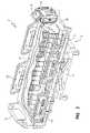
- FIG. 8is an exploded view of an exemplary pneumatic assembly
- FIG. 9is a perspective view of the pneumatic assembly of FIG. 8 ;
- FIG. 10illustrates a functional block diagram illustrating the head zone and seat zone sensors and other system components coupled to a communication network
- FIG. 11illustrates a block diagram for a control system in accordance with the present invention including an algorithm control unit
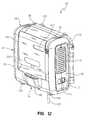
- FIG. 12is a perspective view of a control unit in accordance with the present invention.
- FIG. 13is a perspective view of a control unit with a display portion rotated upward;
- FIG. 14is an exploded perspective view of a control unit housing and coupling of a display portion to the control unit housing;
- FIG. 15is a perspective view of a control unit with a portion of the housing removed to show internal components
- FIG. 16is a perspective view of a control unit with a portion of the housing removed to show other internal components
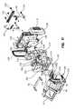
- FIG. 17is an exploded perspective view of internal components of a control unit from the perspective of a person facing the front side of the control unit;
- FIG. 18is an exploded perspective view of internal components of a control unit from the perspective of a person facing the back side of the control unit;
- FIG. 19is a schematic block diagram of an internal architecture of a control unit
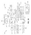
- FIG. 20is a schematic block diagram of an internal architecture of a display board of a control unit
- FIG. 21is a schematic block diagram of an internal architecture of an algorithm control board of a control unit
- FIGS. 22 A-Dare exemplary user interfaces for a main display screen of a control unit
- FIG. 23is an exemplary user interface for a pull down menu for a control unit
- FIG. 24is an exemplary user interface for configuring alarm settings of a control unit
- FIGS. 25 A-Dare exemplary user interfaces for configuring selected alarm types
- FIGS. 26 A-Dare exemplary user interfaces for configuring other alarm types
- FIG. 27is an exemplary user interface for a surface pressure map
- FIGS. 28 A-Dare exemplary user interfaces for configuring a firmness override feature
- FIGS. 29 A-Bare exemplary user interfaces for viewing instructional material relating to a patient support
- FIGS. 30 A-Fare exemplary user interfaces for monitoring a pressure relief feature
- FIGS. 31A-Dare exemplary user interfaces for monitoring a turn-assist feature
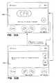
- FIGS. 32A-Bare exemplary user interfaces for monitoring a CPR feature
- FIG. 33is an exemplary user interface for initial mattress setup.
- FIG. 34is an exemplary user interface for entering patient weight.
- FIG. 1shows an embodiment of a control unit 42 positioned on an exemplary bed 2 .
- Control unit 42is configured to control certain automated features of mattress 10 .
- Mattress 10may be any suitable mattress having one or more automated features.
- FIG. 2shows an illustrative embodiment of a patient support or mattress 10 having automated features in accordance with the present invention.
- Patient support 10can accommodate a patient of any size, weight, height or width. It is also within the scope of the present invention to accommodate bariatric patients of up to 1000 pounds or more. To accommodate patients of varied sizes, the patient support may include a width of up to 50 inches or more.
- Bed 2is a hospital bed including a frame 4 , a headboard 36 , a footboard 38 , and a plurality of siderails 40 .
- Frame 4 of the exemplary bed 2generally includes a deck 6 supported by a base 8 .
- Deck 6includes one or more deck sections (not shown), some or all of which may be articulating sections, i.e., pivotable with respect to base 8 .
- patient support 10is configured to be supported by deck 6 .
- Patient support 10has an associated control unit 42 , which controls automated features of patient support 10 , such as inflation and deflation of internal components of patient support 10 .
- Control unit 42includes a user interface 44 , which enables caregivers, service technicians, and/or service providers to configure patient support 10 according to the needs of a particular patient. For example, support characteristics of patient support 10 may be adjusted according to the size, weight, position, or activity level of the patient.
- User interface 44is password-protected or otherwise designed to prevent access by unauthorized persons.
- User interface 44also enables patient support 10 to be adapted to different bed configurations.
- deck 6may be a flat deck or a step or recessed deck.
- An end usermay select the appropriate deck configuration via user interface 44 .
- Inflation or deflation of specific mattress componentsmay occur in response to user selection of a hospital bed frame or deck configuration.
- patient support 10has a head end 32 generally configured to support a patient's head and/or upper body region, and a foot end 34 generally configured to support a patient's feet and/or lower body region.
- Patient support 10includes a cover 12 which defines an interior region 14 .
- interior region 14includes a first layer 20 , a second layer 50 , and a third layer 52 .
- Other embodiments of the present inventionmay not include all three of these layers, or may include additional layers.
- first layer 20includes a support material
- second layer 50includes a plurality of vertically-oriented inflatable bladders located underneath the first layer 20
- third layer 52includes a plurality of pressure sensors located underneath the vertical bladders of second layer 50 .
- a plurality of bolsters 54are also located within interior region 14 of the exemplary patient support.
- one or more filler portions 56are also located within interior region 14 of the exemplary patient support.
- a fire-resistant materialmay also be included in the interior region 14 .
- Patient support 10may be coupled to deck 6 by one or more couplers 46 .
- couplers 46are conventional woven or knit or fabric straps including a D-ring or hook and loop assembly or Velcro®-brand strip or similar fastener.
- Other suitable couplers, such as buttons, snaps, or tethersmay also be used.
- FIG. 4Components of the illustrated embodiment of a patient support in accordance with the present invention are shown in exploded view in FIG. 4 .
- This embodiment of patient support 10includes a top cover portion 16 and a bottom cover portion 18 .
- Top cover portion 16 and bottom cover portion 18couple together by conventional means (such as zipper, Velcro® strips, snaps, buttons, or other suitable fastener) to form cover 12 , which defines interior region 14 .
- conventional meanssuch as zipper, Velcro® strips, snaps, buttons, or other suitable fastener
- First support layer 20is located below top cover portion 16 in interior region 14 .
- First support layer 20includes one or more materials, structures, or fabrics suitable for supporting a patient, such as foam, inflatable bladders, or three-dimensional material. Suitable three-dimensional materials include Spacenet, Tytex, and/or similar materials.
- a second support layer 50 including one or more inflatable bladder assembliesis located underneath the first support layer 20 .
- the illustrated embodiment of the second support layer 50includes first, second and third bladder assemblies, namely, a head section bladder assembly 60 , a seat section bladder assembly 62 , and a foot section bladder assembly 64 .
- Other embodimentsinclude only one bladder assembly extending from head end 32 to foot end 34 , and other arrangements of multiple bladder assemblies, for example, including an additional thigh section bladder assembly.
- bladder assemblies disclosed hereinare formed from a lightweight, flexible air-impermeable material such as a polymeric material like polyurethane, urethane-coated fabric, vinyl, or rubber.
- a pressure-sensing layer 69illustratively including first and second sensor pads, namely a head sensor pad 68 and a seat sensor pad 70 , is positioned underneath bladder assemblies 60 , 62 , 64 .
- Head sensor pad 68is generally aligned underneath head section bladder assembly 60
- seat sensor pad 70is generally aligned underneath seat section bladder assembly 62 , as shown.
- Head filler 66may be positioned adjacent head sensor pad 68 near head end 32 so as to properly position head sensor pad 68 underneath the region of patient support 10 most likely to support the head or upper body section of the patient.
- a single sensor pad or additional sensor padsfor example, located underneath foot section bladder assembly 64 , and/or different alignments of the sensor pads, are provided.
- a turn-assist cushion or turning bladder or rotational bladder 74is located below sensor pads 68 , 70 .
- the exemplary turn-assist cushion 74 shown in FIG. 4includes a pair of inflatable bladders 74 a , 74 b .
- Another suitable rotational bladder 74is a bellows-shaped bladder.
- Another suitable turn-assist cushionis disclosed in, for example, U.S. Pat. No. 6,499,167 to Ellis, et al., which patent is owned by the assignee of the present invention and incorporated herein by this reference.
- a plurality of other support components 66 , 72 , 76 , 78 , 80 , 84 , 86 , 90are also provided in the mattress of FIG. 4 .
- One or more of these support componentsare provided to enable patient support 10 to be used in connection with a variety of different bed frames, in particular, a variety of bed frames having different deck configurations.
- One or more of these support componentsmay be selectively inflated or deflated or added to or removed from patient support 10 in order to conform patient support 10 to a particular deck configuration, such as a step or recessed deck or a flat deck.
- the support components illustrated in FIG. 4are made of foam, inflatable bladders, three-dimensional material, other suitable support material, or a combination of these.
- head filler 66includes a plurality of foam ribs extending transversely across patient support 10 . Head filler 66 could also be an inflatable bladder.
- Filler portion 72includes a foam layer positioned substantially underneath the sensor pads 68 , 70 and extending transversely across the patient support 10 . In the illustrated embodiment, filler portion 72 includes a very firm foam, such as polyethylene closed-cell foam, with a 1 ⁇ 2-inch thickness.
- Head bolster assembly 76seat bolster assembly 78 , and foot section bolster assembly 86 each include longitudinally-oriented inflatable bladders spaced apart by coupler plates 144 .
- first foot filler portion 80includes a plurality of inflatable bladders extending transversely across patient support 10
- second foot filler portion 84includes a foam member, illustratively with portions cut out to allow for retractability of the foot section or for other reasons.
- Deck filler portion 90includes a plurality of transversely-extending inflatable bladders. As illustrated, deck filler portion 90 includes two bladder sections located beneath the head and seat sections of the mattress, respectively, and is located outside of cover 12 . Deck filler portion 90 may include one or more bladder regions, or may be located within interior region 14 , without departing from the scope of the present invention.
- a pneumatic valve box 58 and an air supply tube assembly 82are also provided in the illustrated embodiment.
- Receptacle 88is sized to house pneumatic valve box 58 .
- receptacle 88is coupled to bottom cover portion 18 by Velcro® strips.
- Pneumatic box 58 and tube assembly 82are described below with reference to FIG. 5 , and FIGS. 8-9 .
- support layer 20includes a breathable or air permeable material which provides cushioning or support for a patient positioned thereon and allows for circulation of air underneath a patient.
- the circulated airmay be at ambient temperature, or may be cooled or warmed in order to achieve desired therapeutic effects.
- support layer 20includes or is enclosed in a low friction air permeable material (such as spandex, nylon, or similar material) enclosure that allows support layer 20 to move with movement of a patient on patient support 10 , in order to reduce shear forces, for instance.
- a low friction air permeable materialsuch as spandex, nylon, or similar material
- the enclosureis made of a non-air permeable, moisture/vapor permeable material such as Teflon or urethane-coated fabric.
- FIG. 5A schematic diagram of the pneumatic control system of patient support 10 is shown in FIG. 5 . Reading FIG. 5 from left to right, there is shown a simplified top view of patient support 10 with portions removed to better illustrate the various air zones 160 , a simplified side view of patient support 10 , a schematic representation of pneumatic valve box 58 , a schematic representation of control unit 42 , and air lines 146 , 148 , 150 linking control unit 42 , valve box 58 , and air zones 160 .
- air zones 160 of patient support 10are assigned as follows: zone 1 corresponds to head section bladder assembly 60 , zone 2 corresponds to seat section bladder assembly 62 , zone 3 corresponds to foot section bladder assembly 64 , zone 4 corresponds to upper side bolsters 140 , zone 5 corresponds to lower side bolsters 142 , zone 6 corresponds to upper foot bolsters 140 , zone 7 corresponds to lower foot bolsters 142 , zone 8 corresponds to first turn-assist bladder 74 , zone 9 corresponds to second turn-assist bladder 74 , zone 10 corresponds to deck filler 90 , and zone 11 corresponds to foot filler 80 .
- Valve box 58is located in the foot section 34 of patient support 10 .
- valve box 58is releasably coupled to bottom portion 18 of cover 12 in interior region 14 , i.e., by one or more Velcro®-brand fasteners or other suitable coupler.
- Each air line 150is coupled at one end to an inlet port 135 on the corresponding bladder or bladder assembly. Each air line 150 is coupled at its other end to a valve assembly 162 .
- Each valve assembly 162includes first or fill valve 163 and a second or vent valve 165 .
- First valves 163are coupled to air supply 152 of control unit 42 by air lines 148 . First valves 163 thereby operate to control inflation of the corresponding zone 160 i.e. to fill the zone with air.
- Second valves 165operate to at least partially deflate or vent the corresponding zone 160 , for example, if the internal air pressure of the zone 160 exceeds a predetermined maximum, or if deflation is necessary or desirable in other circumstances (such as a medical emergency, or for transport of patient support 10 ).
- Each valve 163 , 165has an open mode 224 and a closed mode 226 , and a switching mechanism 228 (such as a spring) that switches the value from one mode to another based on control signals from control unit 42 .
- a switching mechanism 228such as a spring
- closed mode 226air flows from air supply 152 through the value 163 to the respective zone 160 to inflate the corresponding bladders, or in the case of vent valves 165 , from the zone 160 to atmosphere.
- open mode 224no inflation or deflation occurs.
- an emergency vent valve 230is provided to enable quick deflation of turning bladders 74 which draws air from atmosphere through a filter 164 and also vents air to atmosphere through filter 164 .
- Air supply 152is an air pump, compressor, blower, or other suitable air source.
- Air supply 152is coupled to a switch valve 166 by air line 146 .
- Switch valve 166operates to control whether inflation or deflation of a zone occurs.
- An optional proportional valve 171may be coupled to air line 148 to facilitate smooth inflation or deflation of turn-assist bladders 74 , or for other reasons.
- valve box 58includes a first valve module 156 and a second valve module 158 .
- First valve module 156includes valves generally associated with a patient's first side and second valve module 158 includes valves generally associated with a patient's second side.
- the various zones 160are separately inflatable. Certain of the zones 160 are inflated or deflated to allow patient support 10 to conform to different bed frame configurations.
- the deck filler 90(zone 10 in FIG. 5 ) is inflated to conform patient support 10 to certain bed frame configurations, such as step deck configurations including the TotalCare® and CareAssist® bed frames, made by Hill-Rom, Inc., the assignee of the present invention, but is deflated when patient support 10 is used with a flat deck bed frame, such as the Advanta® bed made by Hill-Rom, Inc.
- the foot filler 80zone 11 in FIG.
- the lower side bolsters 142(zone 5 in FIG. 5 ) are not inflated when patient support 10 is used with a VersaCare® bed.
- the lower foot bolsters 142(zone 7 in FIG. 5 ) are inflated when patient support 10 is used on flat decks or other bed frames, including the Advanta® and VersaCare® bed frames made by Hill-Rom, Inc.
- FIGS. 6 and 7are a simplified schematic diagram of a control system for a patient support or mattress 10 in accordance with the present invention.
- FIG. 6schematically illustrates the patient support 10 including the various components of patient support 10
- FIG. 7schematically illustrates the control unit 42 and various components therein.
- the patient support 10includes the sensor pad 52 which is coupled to the pneumatic valve control box 58 as previously described.
- the sensor pad 52includes a head sensor pad 68 and a seat sensor pad 70 .
- the head sensor pad 68is located at the head end 32 of the mattress 10 .
- the seat sensor pad 70is located at a middle portion of the mattress 10 which is located between the head end 32 and a location of the pneumatic valve control box 58 .
- the seat sensor pad 70is located such that a patient laying upon the mattress 10 may have its middle portion or seat portion located thereon when in a reclined state. In addition, when the head end 32 of the mattress 10 is elevated, the seat portion of the patient is located above the seat sensor pad 70 .
- the head sensor pad 68is located beneath the head section bladder assembly 60 and the seat sensor pad 70 is located beneath the seat section bladder assembly 62 .
- Each one of the sensors of the head sensor pad 68 or the seat sensor pad 70is located beneath or at least adjacent to one of the upstanding cylindrical bladders or cushions 50 .
- a head angle sensor 502is coupled to the control box 58 where signals received from the sensor may provide head angle information and pressure adjustment information for adjusting pressure in the seat bladders 62 .
- the sensor pad 52is coupled through the associated cabling to the pneumatic control box 58 .
- the pneumatic control box 58includes a multiplexer 508 coupled to the head sensor pad 68 and the seat sensor pad 70 through a signal and control line 510 .
- the multiplexer board 508is also coupled to an air control board 512 which is in turn coupled to a first valve block 514 and a second valve block 516 .
- a communication/power line 518is coupled to the control unit 42 of FIG. 7 .
- a ventilation supply line 520which provides for air flow through the patient support 10 for cooling as well as removing moisture from the patient is also coupled to the control unit 42 of FIG. 7 .
- An air pressure/vacuum supply line 522 for inflating or deflating air bladdersis coupled to the control unit 42 as well.
- the control unit 42 of FIG. 7includes the display 44 , which displays user interface screens, and a user interface input device 524 for inputting to the control unit 42 user selectable information, such as the selection of various functions or features of the present device.
- the selections made on the user interface input device 524control various aspects of the operation of the patient support 10 , which can include selectable pressure control of various bladders within the mattress 10 , control of the deck 6 , for instance to put the bed 2 in a head elevated position, as well as displaying the current state of the mattress or deck position, and other features.
- An algorithm control board 526is coupled to the user interface input device 524 .
- the algorithm control board 526receives user generated input signals received through the input device 524 upon the selection of such functions by the user.
- the input device 524can include a variety of input devices, such as pressure activated push buttons, a touchscreen, as well as voice activated or other device selectable inputs.
- the algorithm control board 526upon receipt of the various control signals through the user input device 524 controls not only the operation of the mattress 10 but also a variety of other devices which are incorporated into the control unit 42 .
- the algorithm control board 526is coupled to a display board 528 which sends signals to the display 44 to which it is coupled.
- the display board 528is also connected to an output device, e.g., a speaker 530 , which generates audible signals which might indicate the selection of various features at the input device 24 or indicate a status of a patient positioned on patient support (e.g. exiting) or indicate a status of therapy being provided to the patient (e.g., rotational therapy complete).
- the algorithm control board 526receives the required power from power supply 532 which includes an AC input module 534 , typically coupled to a wall outlet within a hospital room or other patient care or healthcare facility.
- the algorithm control board 526is coupled to an air supply, which, in the illustrated embodiment includes a compressor 536 and a blower 538 . Both the compressor 536 and the blower 538 receive control signals generated by the algorithm control board 526 .
- the compressor 536is used to inflate the air bladders in accordance with instructions received from the algorithm control board 526 .
- the blower 538is used for air circulation which is provided through the ventilation supply line 520 to the mattress 10 . It is, however, possible that the compressor 536 may be used to both inflate the bladders and to circulate the air within the mattress 10 .
- a pressure/vacuum switch valve 540is coupled to the compressor 536 which is switched to provide for the application of air pressure or a vacuum to the mattress 10 .
- a muffler 541is coupled to the valve 540 .
- the valve 540In the pressure position, air pressure is applied to all or a portion of the mattress 10 to inflate the mattress or portion thereof for support of the patient.
- the valve 540In the vacuum position, the valve 540 is used to apply a vacuum to the bladders therein such that the mattress may be placed in a collapsed state for moving to another location or for providing a CPR function, for example.
- a CPR button 542is coupled to the algorithm control board 526 .
- An identification tag 544may also be associated with the control unit 42 .
- the identification tag 544may be affixed to an exterior surface of the control unit housing, or may be installed within the interior region of the control unit housing.
- the ID tagmay include bar code, or magnetic strip, or may generate an infrared, radio frequency, or other suitable electromagnetic signal indicating a unique identifier associated with the control unit 42 .
- Such unique identifiermay be used to locate, track, or monitor the status of the control unit, for example, using a locating and tracking system.
- a locating and tracking systemis disclosed in U.S. Pat. No. 6,462,656 to Ulrich, et al., assigned to the assignee of the present invention and incorporated herein by this reference.
- the algorithm control board 526 , the compressor 536 , the blower 538 , and the user input device or user control module 524are located externally to the mattress and are a part of the control unit 42 , which may be located or removably positioned on the footboard 38 as shown in FIG. 1 .
- the sensors and sensor pad 52 , the pneumatic valve control box 58 , and the air control board or microprocessor 512 for controlling the valves and the sensor pad system 52are located within the mattress 10 . It is within the present scope of the invention to locate some of these devices within different sections of the overall system, for instance, such that the algorithm control board 526 could be located within the mattress 10 or the air control board 512 could be located within the control unit 42 .
- control box 58could be combined with control unit 42 and be positioned outside the mattress 10 .
- control box 58includes a multiplexer 252 and an air control board 250 .
- Control board 250is coupled to multiplexer 252 by a jumper 254 .
- Multiplexer 252is further coupled to head sensor pad 68 and seat sensor pad 70 through a signal and control line (not shown).
- Control board 250is also coupled to first valve module 156 and second valve module 158 by wire leads 251 .
- a communication/power line 258couples control board 250 to the control unit 42 .
- Communication line 258couples to a communication plug 259 of control board 250 .
- Jumper 254couples multiplexer 252 to control board 250 for power and access to communication line 258 .
- Wire leads 251provide actuation power to first and second valve modules 156 , 158 .
- An angle sensor cable 256is provided to send a signal from a head angle sensor 502 to the control board 250 .
- Angle sensor cable 256couples to an angle plug 257 of control board 250 .
- head angle sensor 502is located within head bolster assembly 76 .
- Head angle sensor 502indicates the angle of elevation of the head end 32 of bed 2 as the head section of the frame 4 articulates upwardly raising the patient's head or downwardly lowering the patient's head.
- angle sensor 502transmits the angle of head end 32 to all nodes or circuit boards within the mattress control system 42 , 58 .
- Angle sensor 502generates an indication or indicator signal when head end 32 is at an angle of at least 5°, at least 30°, and at least 45°.
- the head angle indicationis transmitted to the control unit 42 which evaluates and processes the signal.
- head end 32When head end 32 is at an angle above 30° turn assist 74 becomes inoperative primarily for patient safety reasons.
- head end 32 is at an angle above 45° informationis transmitted to control unit 42 for use in the algorithms.
- the 5° angle indicationis primarily to ensure relative flatness of patient support 10 .
- angle sensor 502is a ball switch or string potentiometer.
- first and second valve modules 156 , 158include fill valves 163 and vent valves 165 .
- First valve module 156includes fill valves 163 a - f and vent valves 165 a - f .
- Second valve module 156includes fill valves 163 g - l and vent valves 165 g - l .
- Fill valves 163 a - l and vent valves 165 a - lare 12 Volt 7 Watt solenoid direct active poppet style valves in the illustrated embodiment.
- Control board 252is able to actuate each fill valve 163 a - l and vent valve 165 a - l independently or simultaneously.
- Fill valves 163 a - l and vent valves 165 a - lare all able to be operated at the same time.
- control board 250sends a signal to the valve to be operated.
- the signalcauses a coil (not shown) within each valve to energize for 1 ⁇ 2 second and then switches to pulsate power (i.e., turn on and off at a high rate) to save power during activation.
- the activationin turn cause the valve to either open or close depending on which valve is initiated.
- Air line 148includes an outer box line assembly 260 and an inner box line assembly 262 .
- Outer box line assembly 260includes an exterior inlet hose 264 and an elbow 266 coupled to exterior inlet hose 264 .
- Inner box line assembly 262includes an interior inlet hose 268 coupled to elbow 266 , a union tee connector 270 , a first module hose 272 , and a second module hose 274 .
- Connector 270includes a first opening 276 to receive interior inlet hose 268 , a second opening 278 to receive first module hose 272 , and a third opening 280 to receive second module hose 274 .
- First and second module hoses 272 , 274each couple through a male coupler 282 to first and second valve modules 156 , 158 respectively.
- air from air supply 152travels through supply line 148 , enters outer box line assembly 260 through exterior inlet hose 264 and passes through elbow 266 to interior inlet hose 268 .
- the airthen travels from inlet hose 268 to union tee connector 270 where the air is divided into first module hose 272 and second module hose 274 .
- the airpasses through first and second module hoses 272 , 274 into first and second valve modules 156 , 158 respectively.
- the operation of first and second valve modules 156 , 158is described below.
- Control box 58includes a base 284 , a cover 286 , and a tray 288 .
- Cover 286includes a plurality of fasteners (i.e., screws) 290 .
- Base 284includes a plurality of threaded cover posts 292 .
- Cover posts 292are configured to receive screws 290 to couple cover 286 to base 284 .
- Cover 286 and base 284define an inner region 298 .
- Tray 288couples to base 284 with a plurality of rivets 291 riveted through a plurality of rivet holes 293 located on tray 288 and base 284 .
- Inner box line assembly 262 , first valve module 156 , second valve module 158 , control board 250 , and multiplexer 252are contained within inner region 298 .
- Base 284further includes a plurality of control board posts 294 , a plurality of multiplexer posts 296 , and a plurality of module posts 300 .
- First and second valve modules 156 , 158are coupled to module posts 300 by shoulder screws 302 and washers 304 .
- Control board 250 and multiplexer 252are respectively coupled to control board posts 294 and multiplexer posts 296 by a plurality of snap mounts 306 .
- First and second valve modules 156 , 158attach to third air lines 150 a, b, d - f , and g - l through a plurality of couplers 308 .
- Couplers 308include a first end 310 and a second end 312 .
- Third air lines 150 a, b, d - f , and g - leach include a fitting (not shown) receivable by second end 312 .
- Each first end 310mounts to a port 314 in first and second valve modules 156 , 158 .
- First end 310mounts through a plurality of openings 316 in base 284 .
- a plurality of feedback couplers 318mount through a plurality of feedback openings 320 in base 284 .
- Feedback couplers 318include a first feedback end 322 and a second feedback end 324 .
- First feedback end 322couples to a feedback line (not shown) that in turn couples to a feedback port 135 located on each air zone 160 .
- Second feedback end 324receives a feedback transfer line 326 .
- Each transfer line 326couples to a pressure transducer 328 located on the control board 250 .
- Pressure transducer 328receives the pressure from each air zone 160 and transmits to control unit 42 a pressure data signal representing the internal air pressure of the zone 160 .
- Control unit 42uses these pressure signals to determine the appropriate pressures for certain mattress functions such as CPR, patient transfer, and max-inflate. Pressure signals from the transducer 328 coupled to the foot zone 160 k are also used to maintain optimal pressure in foot zone 160 k . In the illustrated embodiment, pressure in foot zone 160 k (zone 3 ) is computed as a percentage of the pressure in seat zone 160 e (zone 2 ). The pressures in seat zone 160 e and head zone 160 f are determined using both the transducers 328 and the pressure sensors 136 . The pressures in one or more of the zones 160 may be adjusted in real time.
- fill valves 163 a - l and vent valves 165 a - lare coupled to various portions of patient support 10 through third air lines 150 a, b, d - f , and g - l .
- Fill valve 163 a and vent valve 165 aare coupled to upper foot bolsters 140 c
- fill valve 163 b and vent valve 165 bare coupled to lower side bolsters 142 a, b
- fill valve 163 cis coupled to atmosphere and vent valve 165 c is reserved for future therapies.
- fill valve 163 d and vent valve 165 dare coupled to first turn assist 74 a
- fill valve 163 e and vent valve 165 eare coupled to seat bladders 62
- fill valve 163 f and vent valve 165 fare coupled to head bladder assembly 60
- fill valve 163 g and vent valve 165 gare coupled to foot filler 80
- fill valve 163 h and vent valve 165 hare coupled to upper side bolsters 140 a, b
- fill valve 163 i and vent valve 165 iare coupled to deck filler 90
- fill valve 163 j and vent valve 165 jare coupled to first turn assist 74 b
- fill valve 163 k and vent valve 165 kare coupled to foot bladders 164
- fill valve 163 l and vent valve 165 lare coupled to lower foot bolsters 142 c .
- Vent valves 165 d, jare biased in the open position to vent air from first and second turn assist 74 a , 74 b when first and second turn assist 74 a , 74 b are not in use. Vent valves 165 d, j return to their open position if the mattress loses power or pressure venting air from the first and second turn assist 74 a , 74 b .
- the pressure in the zone 160 after deflationis determined by the control system 42 , 58 in real time rather than being predetermined.
- a userenters an input command to control unit 42 .
- Control unit 42processes the input command and transmits a control signal based on the input command through communication line 258 to control board 250 .
- control signalscould be based on operational information from control unit 42 to increase or decrease pressure within one or more of the zones 160 based on information obtained from transducers 328 and/or sensors 136 .
- the mattress controls 42 , 58are independent from operation of the bed frame 4 .
- bed frame 4 and mattress 10may be configured to exchange or share data through communication lines.
- datamay be communicated from bed frame 4 to mattress system 42 , 58 and used to adjust support parameters of mattress 10 .
- a signalis transmitted from frame 4 when foot section 34 is retracting, so that mattress systems 42 , 58 responds by decreasing internal pressure of vertical bladders 50 in foot assembly 64 .
- air supply 152is capable of supplying air or acting as a vacuum to remove air from zones 160 .
- a microprocessor on control board 250actuates corresponding fill valve 163 a - l or vent valve 165 a - l based on the control signal from control unit 42 . For example, if the control signal indicates the pressure in head bladder assembly 160 is to be increased fill valve 163 f is actuated. However, if the control signal indicates the pressure in head bladder assembly 160 is to be decreased vent valve 165 f is actuated. While in vacuum mode one or more fill valves 163 a - l may be actuated to allow for rapid removal of air within the corresponding zones.
- FIG. 10illustrates an overall system architecture 570 of a mattress in accordance with the present invention.
- the multiplexer board 508also known as a sensor communication hub, is coupled to the head zone sensor 68 and the seat zone sensor 70 .
- the multiplexer 508 as well as the optical system devicesincludes a number of sensory algorithms to be described later herein.
- the algorithm control unit 526which includes a second set of sensory algorithms 574 and control algorithms 576 .
- the output of the multiplexer 508 and the algorithm control unit 526are coupled to a network 578 which is also coupled to the air control unit 512 and the LCD display unit 44 .
- the network 578includes interface hardware, also known as a communication hub.
- the network 578acts as the communication bus for the various hardware, software, and firmware control devices.
- the multiplexer 508includes the sensory algorithms 572 .
- the algorithm control unit 526also includes sensory algorithms which may include algorithms for providing pressure relief, for providing a motion metric, for providing weight estimation, and for providing information to a LCD module which includes a calculation of statistics model.
- FIG. 11illustrates a block diagram of a control system 580 incorporating the LCD display unit 44 , the air control board 512 , the communication hub or network 508 , and the algorithm control unit 526 .
- the communication hub 508which receives sensor data from the head zone sensor 68 and the seat zone sensor 70 is coupled to both the LCD display unit 44 and the algorithm control unit 526 through a first sensor data line 582 and a second sensor data line 584 respectively.
- the algorithm control unit 526includes sensory algorithms 574 and control algorithms 576 .
- the algorithm control unit 526includes a first output line 586 coupled to the LCD display unit 44 for transmitting patient position monitor status, a second control line 588 for communicating movement status, and a third control line 590 for communicating the status of the algorithm control unit.
- the algorithm control unit 526includes a fourth output line 592 which transmits the zone pressure boundary values for each of the head, seat and foot zones to the air control board 512 to which the line 592 is coupled.
- the air control board 512which includes the pressure sensors previously described, sends control pressure zone feedback signals through a line 594 back to the algorithm control unit 526 .
- the display unit 44 through the user input interface device 524also sends control signals to the algorithm control unit 526 through a control line 596 which includes signals such as various mode command signals as well as bed type command signals for adjusting the frame or deck of the bed.
- the present inventionincludes sensory algorithms as well as control algorithms.
- the sensory algorithmsare provided in firmware located within the multiplexer 508 and the algorithm control unit 526 .
- Sensory algorithmsinclude the following: bottom out detection, where a portion of the subject is supported by the bed frame as opposed to the surface, bed exit detection, sitting on the side of a bed detection, detection of a patient lying on the edge of the surface, detecting a lack of patient movement on the surface over a period of time, providing patient position monitoring by distinguishing between the following six positions left lying, left sitting, center lying, center sitting, right lying, right sitting, and measuring patient weight within plus or minus 20% within the bed and the flat position.
- the control system algorithmswhich are located in the control system algorithm firmware 576 optimize pressure reduction by dynamic load distribution adjustment of the surface air bladders of the mattress 10 located above the head sensor pad 68 and the seats sensor pad 70 .
- the illustrated embodiment of the control unit 42includes a housing 22 .
- the exterior housing 22includes a top end 26 , a bottom end 28 , a first side 92 , and a second side 94 .
- the exterior housing 22defines an interior region containing control unit components to be described later herein.
- a display portion 24is pivotably coupled to the housing 22 . Also shown coupled to the exterior housing 22 are a rotatable handle 98 , a coupling assembly including first and second hangers 100 , 102 , an air filter 110 , an electrical power input port 112 , a power on/off switch 114 , first and second feet 104 , 106 , and a cable 108 .
- a visual indicator or light bar 96is also provided.
- the display portion 24is shown rotated upwardly into a use position. Once placed in a use position, the display panel 116 may be easily viewed by a caregiver.
- the display panel 116is, in the illustrated embodiment, a liquid crystal display including a touchscreen control panel such that the user may simply touch the screen with a fingertip in designated areas to give instructions for controlling the patient support.
- the video display panel 116is configured to be capable of displaying video clips and help screens, including videos that demonstrate operation, installation, and/or maintenance procedures for the patient support 10 . All aspects of the user interface of display panel 116 are capable of being displayed in multiple languages, including, for example, English and Spanish.
- the display panel 116is, in the illustrated embodiment an 8.4 inch high contrast mode flip up LCD display screen.
- an infrared (IRDA) port 118which enables data collection and/or communication over a network using wireless technology. For example, usage data regarding usage of the mattress 10 , and/or service information (i.e. how often the mattress has been serviced) may be communicated to a remote computing device over a wireless network through the use of the infrared port 118 .
- IRDAinfrared
- a memory port 120is also provided in the display portion 24 .
- Memory port 120is configured to removably receive memory cards such as compact flash memory, for example.
- SD memory cardsmay also be used, for example, in order to configure the control unit 42 with firmware upgrades, changes to the software, or updates or additional training or service videos. This eliminates the need to take the control unit 42 out of service in order to accomplish these and other types of upgrades and adjustments.
- cover panels 122 , 124are removably coupled to exterior housing 128 of the display portion 24 .
- Cover panels 122 , 124are generally made of the same material as the rest of the exterior housing of display portion 24 (i.e., polycarbonate).
- Cover panels 122 , 124are provided primarily to protect the communication and data ports 118 , 120 when those ports are not in use.
- Cover panels 122 , 124may be coupled to exterior housing 128 by one or more fasteners 126 (i.e., screws).
- Exterior housing 128may also include a bracket configured to mate with a mating portion of a footboard, headboard, siderail or other similar port of a bed.
- the usage data or service data that may be collected and transmitted through the infrared port 118may include error logs or logs of the mattress usage.
- FIG. 14shows a simplified exploded view of internal components of the display portion 24 .
- the front or top portion 128 of the exterior housing of display portion 24is coupled to a back or bottom portion 130 by a series of fasteners 132 through a series of apertures 134 .
- a pivot coupling assembly 194includes a friction hinge 142 and a circular member 138 which includes a plurality of spaced apart apertures 140 .
- a hollowed out semi-circular region of the display portion 24includes a female end 180 and a male end 178 .
- the pivotable coupling assembly 194is position within the semi-circular region of the display portion 24 as shown by dashed lines 186 , 188 , and 190 .
- Corresponding female 184 and male 182 portionsare provided in the upper end 26 of the exterior housing of the control unit 42 .
- the pivot coupling assembly 194thereby mates with the coupling portions 182 , 184 as shown by dashed lines 186 , 192 .
- a suitable hinge 142is the model MH40 manufactured by Reell Precision Manufacturing Corporation of St. Paul, Minn. (www.reell.com). The hinge 142 allows the display portion 24 to rotate between an upward or raised use position and a lowered or closed storage position as described above. However, the display may be stopped at any position in between the two extreme positions. The range of motion of the pivotable display portion is greater than 180 degrees.
- the video display 24includes a front or top housing 128 , and a back or bottom housing 130 . Within the two housing portions, which define an interior region, are provided a touchscreen 119 positioned above or on top of a liquid crystal display assembly 115 . An insulator (not shown) is provided between the LCD assembly 115 and the printed circuit board or LCD board 121 . An LCD cable 117 couples the display portion 24 to the algorithm control board 196 through an opening in the male portion 178 .
- FIG. 15shows the control unit 42 with the rear housing 234 removed to show certain interior components of the control unit 42 .
- the interior components of the control unit 42include an algorithm control board 526 , a blower 198 , a hose connector 200 , a hose tubing 202 coupling the hose connector 200 to the blower 198 , a pump or compressor 204 , a valve assembly 206 , and a power input assembly 208 . These components are described in greater detail below.
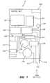
- FIG. 16illustrates a plurality of protective inserts 210 , 212 , 214 which are provided within the interior region of control unit 42 .
- the insertsare aligned within the interior region of the control unit 42 as shown by dashed lines 216 and 218 .
- Each of the inserts 210 , 212 , 214is made of an insulating material such as EPAC (Electronic Packaging Assembly Concept) foam.
- the EPAC foamprovides an internal chassis for the control unit 42 .
- Each of the foam members 210 , 212 , 214has within it one or more cooling channels which allow air to circulate. Such air channels (not shown) may also provide a channel for any leaking blower air to escape.
- the inserts 210 , 212 , 214also function to dampen structural noise.
- additional rubber mountingmay also be provided, for example, on the compressor 204 , in order to improve noise and/or vibration performance.
- FIGS. 17 and 18show exploded views of interior components of the control unit 42 .
- the componentsare viewed from the perspective of a person looking at the front housing 232 .
- the componentsare viewed from the opposite perspective.
- front housing 232includes the display portion 24 , visual indicator or light bar 96 , and CPR button 30 .
- the handle 98is pivotably coupled to the upper end 26 of the front housing 232 .
- the visual indicator or light bar 96includes an LED lens 236 , a lightpipe 238 , and LED board 240 .
- the LED lens 236provides a clear surface for the LED light to penetrate.
- the lensmay be textured or frosted to adjust the dispersion of light.
- the LED lightpipe 238provides a path for the LED light to go through.
- the lightpipe 238is made of a molded plastic. In the illustrated embodiment, the lightpipe 238 is divided into two parts for ease of moldability.
- the lightpipe 238may be textured or frosted to adjust the dispersion of the light.
- the LED board 240is coupled to the algorithm control board 196 to control the operation of the visual indicator or light bar 96 .
- the light bar 96acts to visually alert a caregiver as to a situation involving the mattress 10 , control unit 42 , or patient, that may need attention.
- the light bar 96may be illuminated in green, flashing green, or not illuminated at all, when the control unit and/or mattress is operating normally.
- the light barmay be illuminated intermittently to indicate different modes of normal operation. For example, steady green may indicate pressure relief mode while flashing green may indicate another mode (such as maxinflate, turn assist, etc.)
- a different mode(such as steady on flashing yellow or amber) may be used to indicate when either the control unit or the mattress is in need of service or when an alarm (such as a bed exit alarm, described elsewhere herein) is activated.
- Yet another modemay be used to indicate that the CPR function of the mattress is turned on, that the patient appears to be showing signs of inactivity or distress, or for other purposes.
- the light bar 96may be coupled to the motion monitor feature discussed elsewhere herein so that another visual alert is generated (an orange light, for example) if the patient's motion is above or below an acceptable range.
- the light bar 96may be coupled to one or more of the bed alarm settings discussed elsewhere herein so that a visual alert is generated if the patient is attempting to exit the bed, or lying near the edge of the bed, for example.
- the front housing 232supports the foam insert 214 , into which most of the interior components are loaded.
- the front housing 232outlines and supports the LED lens 236 , light type 238 , and holds the speaker 242 on its flange.
- the front housing 232is made from Noryl structural foam sufficient to withstand applicable drop test requirements.
- the handle 98is attached to the front housing 232 by a pair of shoulder screws.
- the handleis blow molded in polycarbonate.
- the algorithm control board 526is described elsewhere herein, for example with reference to FIGS. 7 and 19 .
- the air line 108is coupled to the switching valve 206 by the inlet and outlet tubing 244 .
- Separate tubing 244 a , 244 bis provided for inlet and outlet hoses.
- the blower 198is a commercially available blower such as Ametek model no. 150166-00.
- the compressor 204is a commercially available compressor such as Thomas model no. 6025SE-XP, part no. 950115.
- the switching valve 206is a pressure/vacuum valve such as is commercially available from Numatics model no. 92114-2.
- the various pneumatic tubing used to interconnect the pneumatic items in the control systemsare generally conventional pneumatic tubing. Also, various connectors and wiring are used to interconnect the electrical items in the control unit 42 and the patient support 10 . Rubber bumpers and screw caps are used to cover and hide screws and other fasteners on the control unit assembly.
- a plurality of labels or label portions 332( FIG. 12 ) are provided as needed to meet marketing and regulatory requirements.
- the power input 246includes a power supply, for example XP model no. ECM130PS12, a power inlet, for example Corcom model no. PE0S0DBX0, and a 120V power filter, such as Corcom model no. 3MZ1.
- a power supplyfor example XP model no. ECM130PS12
- a power inletfor example Corcom model no. PE0S0DBX0
- a 120V power filtersuch as Corcom model no. 3MZ1.
- the foam inserts 210 , 212hold other components in place, for example the insert 212 keeps the blower, compressor, and power supply in position, and the insert 210 keeps the power supply, speaker, and power inlet in proper position.
- the insert 214is also made of EPAC (Electronic Packaging Assembly Concept) foam and is used to hold the algorithm control unit, compressor, blower, switching valve, and power supply in place. The use of these foam inserts 210 , 212 , 214 eliminates the need for a metal chassis and fasteners.
- the first and second end caps 248conceal the screws and other molding issues on the front and back housing 232 , 234 .
- the end capsare made from Santoprene Thermo Plastic Rubber (TPR).
- TPRSantoprene Thermo Plastic Rubber
- the end cap 248also provide cushioning for protection during impacts and drops.
- the first end cap 248positioned proximate to the friction hinge 142 , also includes a set of ribs to help keep the friction hinge in place. It should be noted that the housing portions 232 , 234 , 248 are interlocking walls designed to prevent liquid ingress.
- the filter holder 110positions the foam air filter and maintains it in front of the air inlet ports on the front and back housing 232 , 234 .
- the filter 110is molded in polycarbonate.
- the hose receptacle 200receives and holds the hose end.
- the receptacle 200also holds a gasket to prevent air leakage.
- Attached to the receptacleare one or more air lines and electrical contacts (i.e., three and eight, respectively, in the illustrated embodiment).
- the receptacle to 100is made from Valox or another very strong material.
- the receptacle 200is held in place by the front and back housings 232 , 234 .
- the receptacle and corresponding hoseare described in greater detail in U.S. Provisional Patent Application Ser. No. 60/636,252, assigned to the assignee of the present invention, and incorporated herein by reference.
- the hoseitself includes the electrical contacts and air lines that connect directly to the patient support 10 .
- the rear housing portion 234holds and compresses the back and side foam insert 212 , in order to hold all of the internal components in proper position.
- the rear housing 234also provides mounting points for the hanger assembly 100 , 102 and holds the speaker 242 in place.
- Rear housing 234is made from Noryl structural foam sufficient to withstand applicable drop test requirements.
- the control unit 42may be attached to a footboard or other portion of a bed frame, or may be positioned on the floor.
- Hook assemblies 100 , 102are provided in order to attach the control unit 42 to a portion of a bed, i.e., a footboard.
- the hooksare configured to support at least four times the weight of the control unit 42 , without failing.
- Each of the hooks 100 , 102may be rotated or otherwise reconfigured in various positions in order to adapt to a variety of different footboards or other bed portions.
- a similar suitable hook assemblyis described in U.S. Pat. No. 6,735,799 to Ellis, et al., assigned to the assignee of the present intervention and incorporated herein by this reference.
- Feet 104 , 106are provided primarily to stabilize and protect the control unit 42 when it is positioned on the floor.
- the feet 104 , 106are made of rubber in the illustrated embodiment.
- a pivot cover 222is provided to hold the top pivots of the hook assemblies 100 , 102 coupled to the rear housing 234 .
- the cover 222also is adjustable to control the clearance between the cover 222 and the hooks 100 , 102 .
- a rubber detent 330is provided in order to hold the display portion 24 in place, i.e., in the storage or downward position, for example during transport of the control unit 42 . These detents 330 provide a resistance to upward rotation of the display portion 24 .
- FIG. 19is a simplified system level block diagram for the control unit 42 .
- FIG. 19shows the major components of the control unit 42 , including the display board 528 and the algorithm board 526 .
- the display board 528 and algorithm board 526provide the control functions for the entire mattress system.
- the display board 528provides the primary interface between the end user, technician, or caregiver and the mattress system.
- the display board 528also contains the mattress system's user interface.
- the user interfaceincludes a touchscreen video display.
- the display board 528is also capable of playing video files stored in a memory 550 , using commercially available software such as Windows Media Player. Such video files may be used, for example during system installation and user training.
- the display board 528is also responsible for storing user data and providing access to that data via its IRda infrared port 118 .
- the display boardinterfaces to the algorithm board 526 and to the rest of the mattress system via a CAN bus connection 552 , 554 .
- the algorithm control board 526controls the normal working of the mattress system by executing algorithms that convert user requests into desire actions. These algorithms may be executed, for example, to set proper mattress pressure distribution for a patient, detect patient position, and/or provide patient turning assistance using the turn assist bladders 74 .
- the algorithm board 526provides a CAN bus connection 552 for other system components.
- the algorithm control board 526also provide speed control for the blower 198 , which is used primarily for mattress service cooling.
- the algorithm control board 526also provides power for an ID tracking tag 544 and control of a pressure/vacuum switching valve 540 , which allows for inflation and quick deflation of one or more portions of the mattress 10 .
- the algorithm control board 526also provides switched AC power to the system's compressor 204 via an optically isolated triac circuit.
- the CPR button 542is also connected to the algorithm board 526 .
- the infrared port 118Electrically coupled to the display board 528 are the infrared port 118 , the memory 550 , the speaker 530 , the touchscreen 524 , the liquid crystal display 546 , and the backlight inverter 548 .
- FIG. 20is a simplified block diagram for display board 528 .
- the display board 528includes a 32 bit microcontroller 556 .
- an AMD Au1100 32 bit microcontrolleris used.
- Other suitable microprocessorsinclude the Intel Xscale and Freescale IDOTMX21.
- a CAN microcontrolleris coupled to the main microcontroller 556 in order to provide the CAN function.
- the CAN microcontroller 558is an Atmel T89C51CC01. Coupled to the CAN microcontroller 558 is a CAN transceiver 560 .
- the transceiveris a Philips TJA1054.
- the CAN controller 558communicates with the main microcontroller 556 through a UART.
- a level shifting buffer function 562is provided between these two devices.
- the CAN controller 558may also be used to vary the video display's backlight brightness using one of its pulse width modulated outputs.
- the CAN controller 558also provides a serial interface to the real time clock of the display board 528 .
- a compact flash card or other suitable memory 550may be coupled to the display board microcontroller 556 .
- training videos or other types of videos, for either or both a caregiver and technicians installing using or setting up a patient support 10may be stored on removable flash memory cards which may be connected to the microcontroller.
- the flash memory cards 550may also provide a means for updating software applications and the system operating system.
- a suitable flash memory cardis the Secure Digital (SD) card, however, the Compact Flash (CF) card also has the required capabilities and would work equally as well.
- SDSecure Digital
- CFCompact Flash
- the display board 528 as shownwill support either a CF card or a SD card.
- the primary function of the CAN microcontroller 558 of the display board 528is to translate CAN messages from the mattress system into RS232-based messages for one of the display microcontroller 556 , and to format the display microcontroller's 556 serial messages into CAN messages and send them out on the CAN bus.
- the CAN microcontroller 558has a 80C51COR, 32 kilobytes of flash memory, 2 kilobytes of flash memory for a bootloader, 2 kilobytes EEPROM storage for variables, and a full duplex UART.
- the real time clockis implemented by a Dallas semi-conductor DS13O7Z, which is connected to the serial bus of the CAN microcontroller 558 .
- the LCD backlight 548is implemented using a PWM output of the CAN microcontroller 558 .
- the reset of the display microcontroller 556is implemented by buffering an output of the CAN microcontroller 558 to a reset pin of a supply voltage supervisor 564 .
- a CAN microcontroller 558may be accomplished using standard C programming and microcontroller emulation tools, as well as several commercially available CAN tools such as Micro Vision, Keil 8051 software tools for C, and CANalyzer ProCAN.
- the CAN microcontroller 558acts as the protocol interface between the display board microcontroller 556 and the rest of the mattress system.
- the CAN microcontroller 558provides firmware of great capabilities and also performs self test each time it is powered.
- the CAN microcontroller 558is a pure-2-peer bus, therefore, all messages communicated are available to each component on the bus. Each individual component, therefore, determines which CAN messages require its attention.
- the touchscreen user interface 524is a 5-wire overlay that is controlled by a peripheral controller.
- the peripheral controller 562controls the touchscreen and also provides a digital to analog converter for the audio output to a power amplifier that drives the speaker 530 .
- the peripheral controlleris any controller that has both an audio driver and a 5-wire touchscreen controller such as a Wolfson WM9712L.
- a serial debug port 566is provided for software debugging and also for possible field upgrades, for example by a technician.
- a serial debug port 566connects to a second UART port of the display microcontroller 556 .
- An EJTAG port 568is provided.
- the display microcontroller 556utilizes the EJTAG port 568 for program monitoring, debugging, and access to the MIPSCORE.
- the IRda port 118provides electrically isolated data transfer for the display board 528 .
- the infrared port 118is built into the display microcontroller 556 and supported in software.
- the power of management circuitry 598provides power-up and reset circuitry for the display board 528 . This circuitry is designed to correctly bring the display micro 556 out of a cold power up or out of a warm reset. The power of management circuitry 598 also regulates power for the peripheral devices CAN, memory, peripheral controller.
- the display board 528also include memory.
- the illustrated display board 528supports either or both 128 mega bits SDRAM and 64 mega bit flash memory.
- the liquid crystal display 546is, in the illustrated embodiment, a TFT VGA LCD (640 ⁇ 480) with a TTFL backlight.
- a simplified block diagram for the algorithm board 526is shown in FIG. 21 .
- the algorithm board 526receives converted user directives received by the display board 528 and sent over to CAN bus 554 .
- the algorithm board 526than takes the appropriate action by interacting with the remaining system components.
- the algorithm board 526directly controls the CPR button 542 and also a diagnostic LED light bar 96 , which may be used for trouble shooting on other purposes.
- the microcontroller 604 for the algorithm board 526is the Motorola Free Style MC9S12DJ128BCFU or other suitable 16-bit microcontroller with a 128 kilo bit flash EEPROM that can be upgraded to 256 kilo bits if necessary.
- the algorithm control microcontroller 604includes 8 kilo bits of RAM memory, 2 UART ports, and 7 eight-bit PWM channels also, the algorithm control micro 604 has a built in CAN controller, which supports the current versions of CAN.
- the software for the algorithm board 526was developed using commercially available development tools such as Code Warrier, Metro Werks Professional Edition C compiler.
- the algorithm control board microcontroller 604may also be a Renesas (Mitsubishi) M306N5FCTFP or Renesas, (Hitachi) HD64F2623.
- the algorithm control board microcontroller 604may be any other suitable microcontroller having the required architecture, onchip in-application programming with flash memory, ability to expand the memory without changing the host board, CAN channel, CAN drivers, and required drivers support.
- the CAN bus connection 552includes RJ-45 connectors for all system resources that require access to the CAN bus.
- a Phillips TJA1054 CAN transceiver or other suitable CAN transceiver 606is used to interface the microcontroller 604 to the CAN bus 552 , 554 .
- Poweris supplied by the mattress system to the algorithm board 526 .
- the algorithm boardlinearly regulates the power supply for the board's own logic supply.
- the system's power supplyis also linearly regulated for the ID tracking tag 544 .
- the algorithm 526also distribute power to the display board 526 sensor hub 508 and air control board 512 .
- the blower 198provides high volume low pressure air circulating through a portion of the patient support 10 .
- the microcontroller 604controls the speed of the blower 198 through a PWM output 608 .
- the algorithm control microcontroller 604also provides power to the blower motor via a high current connection 610 , which is monitored by one of the microcontroller's A/D input.
- the microcontroller 604can disable the blower's power if an abnormal current is sensed.
- the microcontroller 604also controls and activates or deactivates the pressure/vacuum valve solenoid 206 , which is located within the control unit 42 .
- the microcontroller output 612are used to control a solenoid driver which activates the switching valve 206 .
- One GPIO pinis provide on the ground side of this solenoid and another GPIO pin is provided on the high side of this solenoid. This high and low side control provides the ability to turn off the solenoid, even if a single component failure occurs in the driver circuit.
- PWM control of the high side switchalso provides the ability to duty-cycle and reduce the average solenoid current, ‘once the solenoid has pulled in’.
- Another output of the microcontroller 604is used to control an optically isolated triac switch 614 for the application of switched AC power to the compressor 204 .
- the triac circuit 614also detects when switched AC is present and optically couples this information back to a microcontroller input for monitoring purposes.
- a pressure sensor input 616is also connected to the microcontroller 604 as described above.
- the touch screen 524includes a resistive 5-wire touchscreen which is used in connection with a liquid crystal display 546 . While less expensive 4-wire touchscreens may also be used, the 5-wire touchscreen is presently preferred.
- a suitable touchscreenis the Elo Accutouch® 8.4 inch touch screen part no. E24724-000.
- An Elo and Intellitouch surface way touchscreenmay also be used.
- the touchscreen 524is used to display mattress control information and options to a caregiver, technician, or other end user, and receive as input directives from the end user.
- the remaining figuresshow examples of user interface screens implemented using touchscreen 524 .
- FIGS. 22A and 22Billustrate user interface screens for a patient support that does not have a patient positioned upon it.
- a graphical depiction of the patient support 622indicates that at the present moment, the head section of the patient support 10 is raised.
- the user interfaceincludes a first display portion 618 and a second display portion 620 .
- the graphical depiction of the patient support 622is provided within the second display portion 620 .
- the first display portion 618includes a plurality of buttons 624 , 626 , 628 , 630 , 632 . Each of these buttons, in the illustrated embodiment, is activatable by human touch or contact with another object. When one of these buttons is activated, an aspect of the button's presentation or molding changes.
- a keylock button 626is darkened to show that the keylock button 626 is activated.
- the keylock button 626is activated none of the other buttons are available.
- the buttonsare indicated as not being available by a change in an aspect of the button's presentation, such as by being grayed out as shown. If the keylock button 626 is activated, then contact with any of the other buttons 624 , 628 , 630 , 632 will not result in the associated function being performed. Contact with the keylock button 626 when it is in the activated mode operates to deactivate the keylock and unlock the touchscreen.
- the touchscreen 524will then remain unlocked for a period of time, for example 2 minutes, or until the keylock button 626 , or another button, is activated.
- the keylock button 626appears grayed out and the other available function buttons appear darkened.
- FIG. 22Bshows the touchscreen 524 with the keylock 626 turned off.
- the menu button 624if activated, brings up a plurality of additional menu options for controlling different features of the patient support 10 .
- the left and right turn assist buttons 628 , 630control the turn assist bladders 74 A and 74 B. Activation of the left turn assist button 628 results in the left turn assist bladder being inflated to assist the caregiver in rotating a patient positioned on the mattress 10 . Activation of the right turn assist button 630 similarly activates the right turn assist bladder to rotate the patient in that direction. Activation of the maxinflate button 632 results in the patient support 10 being over inflated, for example, for CPR therapy.
- FIGS. 22C and 22Dshow similar touchscreen displays with the graphical depiction 622 of the patient support 10 shown in the horizontal position, indicating that the mattress 10 or any portion thereof, is not elevated.
- FIG. 23shows a pull down menu that becomes active when the menu button 624 is depressed.
- the pull down menuincludes a plurality of menu options including alarm settings 636 , motion monitor 638 , surface map 640 , firmness override or “comfort adjust” 642 , language 644 , and in service 646 . Each of these menu options will be described below.
- a screen such as is shown in FIG. 24is then displayed.
- the alarm settings portion of the user interfaceis used for a caregiver or other enduser to configure various available alarms, which would alert a caregiver when the patient may be moving into a position of danger.
- a bed exit alarm 648is provided whereby the caregiver may configure the control unit 42 to alert the caregiver when the patient appears to be preparing to exit the bed.
- FIG. 24there are a number of possible types of bed exit alarms, including sitting up, sitting on the edge, and out of bed.
- the caregivercan elect to be notified when the patient is sitting up, when the patient appears to be sitting on the edge of the bed, or when the patient is already out of the bed.
- the buttonsare activated by contact, and when a button is activated, its presentation is changed as shown.
- edge-lying alarm 650Another available alarm option is the edge-lying alarm 650 . If the edge-lying alarm 650 is active, a caregiver will be notified when the patient is laying up against the edge of the bed.
- the caregivercan then alter the alarm volume by pressing the plus or minus button 652 .
- a graphical display of molded barsindicates the relative loudness of the alarm.
- the alarmis an audible signal, however, it could also be a visual or electronic signal or other appropriate type of alert.
- a similar adjustment for display screen brightness controlmay also be included.
- FIGS. 25A-Dshow examples of pop up user interface windows that may be presented in response to selection of a corresponding bed exit alarm. These pop up windows correspond to the selected button 648 shown on FIG. 24 .
- the pop up windowincludes a silence button 654 and a reset button 656 .
- the silence button 654is used to deactivate the alarm.
- the reset button 656is used to reconfigure the alarm, or reset the alarm parameters to its previous settings.
- the pop up window shown in FIG. 25Ais displayed with the button 654 , 656 darkened in as activated for a period of time, for example fifteen minutes, unless one of the buttons is activated.
- FIGS. 25C and Dillustrate similar pop up windows for other available bed exit alarm selections.
- FIG. 25Cillustrates a pop up window for the patient sitting on the edge of the bed alarm
- FIG. 25Dillustrates a pop up window for the patient out of bed alarm. Note that the graphical depiction of the patient shown in the left hand portion of the pop up window changes depending upon the alarm type selected. If the sitting up bed exit alarm is selected, an alarm will sound when the patient moves away from the head section of the mattress. Thus, the sitting up alarm is a more sensitive alarm as it typically alerts a caregiver when the patient first begins to move.
- an alarmWhen the sitting on the edge of the bed alarm is selected, an alarm will sound when the patient moves away from the center of the mattress toward an egress point. This setting typically alerts a caregiver when the patient is preparing to exit the bed. The out of bed alarm will sound when the patient's presence is no longer detected by the mattress 10 . If the out of bed alarm is selected, the patient is able to move freely within the bed without triggering an alarm, but the caregiver is alerted if the patient leaves the bed.
- FIGS. 26A-26Bshow similar user interface pop up windows that are displayed if the edge-lying alarm 650 is activated.
- the edge-lying alarmWhen the edge-lying alarm is selected, an alarm will sound when the patient is lying off center, on either edge of the bed.
- the caregiveris alerted if the patient may be lying against the side rails or appears to be in danger of rolling out of the bed.
- the pop up windows shown in FIGS. 25C-25Dillustrate a portion of the motion monitoring feature 638 .
- the motion monitoring featureenables caregivers to monitor the level of activity of a patient on the mattress 10 over a period of time.
- a pop up windowindicates that the patient's level of activity has been below a threshold motion monitoring level for a period of ninety minutes.
- the caregiverwas not alerted as to a change in the patient's level of activity.
- the time period for triggering an alertmay be customized.
- the motion monitoring featuresare described in greater detail in U.S. patent application Ser. No. 11/119,635, filed May 2, 2005, assigned to the assignee of the present invention and incorporated herein by reference.
- the alarm settings and motion monitor portions of the user interfaceinclude graphical depictions illustrating the particular feature, i.e., a person lying next to the edge of the bed in the case of the edge lying alarm.
- the graphical depictionchanges depending on the particular alarm setting or motion monitor feature selected.
- FIG. 27shows a user interface display 640 for a surface map 658 .
- the surface map 658is a real-time or snapshot graphical depiction of the distribution of pressure applied to the surface 10 .
- the legend 660shows that darker colors are indicative of higher pressure while lower pressures are indicated by lighter colors in the illustrated embodiment.
- the example surface map 658 shown in FIG. 27shows that pressure appears to be concentrated in the center of the mattress 10 .
- the surface map 658is updated in real time. For example, if a patient moves from a lying down position to a sitting position, the surface map will change to show a greater distribution of pressure in the seat section of the mattress.
- the surface map 658may be used for clinical purposes, such as to allow an enduser to quickly assess a patient's risk of developing pressure ulcers, by showing graphically the areas of higher pressure.
- the surface map 658may also be used by service technicians, for example, to configure or troubleshoot the mattress. Access to the surface map 658 may be restricted, for example, by requirement of a password.
- a firmness override or comfort adjust feature 642is also provided.
- the firmness override featureallows a caregiver to adjust the internal bladder pressure of one or more air bladders in the mattress 10 for patient comfort. For example, if a particular patient prefers a firmer mattress, the internal bladder pressure may be increased.
- the firmness override featureis provided in addition to the automatic pressure relief feature, but this may not always be the case.
- the firmness override featureis described in more detail in U.S. Provisional Patent Application Ser. No. 60/697,748, filed Jul. 8, 2005, and corresponding PCT Patent Application (Attorney Docket No. 8266-1561) filed on the same date herewith, assigned to the assignee of the present invention, and incorporated herein by reference.
- the language menu item 644enables the end user to configure the control unit user interface for a particular language, such as English, Spanish, or French.
- the in service menu item 646allows the end user to obtain information related to servicing of the mattress 10 .
- FIGS. 28A-Dshow example user interface display screens relating to the firmness override or comfort adjust feature 642 .
- a graphical depiction of the mattressis provided, wherein one or more bars 672 are displayed within each portion of the mattress. The number wherein one or more bars 672 are displayed within each portion of the mattress. The number of bars corresponds to the relative internal pressure of the bladders in that particular section of the mattress. For example, in FIG. 28A , the bladder pressure is greater in the head section of the mattress and the foot section of the mattress and the pressure is lower in the seat section of the mattress.
- FIGS. 28B and 28Dillustrate that if a patient is positioned on the mattress 10 , the graphical depiction of the bed changes to include a patient.
- the graphical depictionchanges again to indicate a no turn assist icon 676 and an angle indicator 674 .
- the no turn assist icon 676graphically indicates that the turn assist bladders may not be inflated while the mattress head angle is greater than thirty degrees.
- the angle indicator 674graphically indicates whether the head angle is less than or greater than thirty degrees as shown in FIGS. 28B and 28D .
- the in service menu item 646also provides an online tutorial feature for caregivers, service technicians, and other end users.
- FIGS. 29A and 29Bshow examples of the online tutorial feature.
- FIG. 29Astill graphics are provided to illustrate the use of the turn assist feature, for example.
- the graphics 662are supplemented with text which provides an additional explanation.
- the end usercan activate the show me button 664 to view an online video demonstration of a selected bed feature.
- a video 666 relating to the selected featurei.e., turn assist
- a pause button 670 and a replay button 668are provided to allow the end user to pause the playing of the video at any point or to replay the video.
- FIGS. 30A-30Fillustrate a sequence of example user interface displays that may be provided to communicate the status of an automatic pressure relief feature of the mattress 10 to an end user.
- An example automatic pressure relief featureis described in greater detail in U.S. patent application Ser. No. 11/119,991, filed May 2, 2004, assigned to the assignee of the present invention, and incorporated herein by reference.
- the graphical nature of the display shown in FIGS. 30A-30Fenables the caregiver or other end user to quickly assess the status of the mattress 10 and the patient positioned thereon, as noted above.
- the automatic pressure relief featurebegins optimizing the pressure relief of the mattress 10 automatically.
- FIGS. 30A and 30Cshow an example user interface display when the patient's head angle is greater than thirty degrees from horizontal.
- FIGS. 30D-30Fare similar graphical displays for a patient on a mattress that is in the horizontal (unarticulated) position.
- FIGS. 31A-31Dshow example user interface displays relating to the turn assist feature of the mattress 10 . If a caregiver elects to activate one of the turn assist buttons 628 , 630 , but the bed has side rails and the side rails are in the down position, a warning window 682 will appear prompting the caregiver to raise the side rails to their full position before the turn assist feature will begin operating.
- FIG. 31Dillustrates a user interface display that is shown if the caregiver selects the left turn assist button 628 . This display graphically depicts a patient 684 being rotated to the left. A similar graphical depiction is provided in FIG. 31C for activation of the right turn assist feature 630 .
- a pop up windowsuch as shown in FIG. 31D is displayed.
- This display 686includes an indication that the head angle of the mattress must be lowered below thirty degrees in order for the turn assist feature to be utilized. If the turn assist feature is already running when the head angle increases above thirty degrees, then the turn assist feature stops running. If the head section of the mattress is at an angle of less than thirty degrees from the horizontal position then no pop up window is displayed and the turn assist feature can continue.
- FIGS. 32A and 32Billustrate example graphical displays that would be presented to an end user on the display portion 24 if the CPR button 30 is activated or the maxinflate button 632 is activated.
- a message 688is provided to indicate to the caregiver that the CPR or max inflate feature is in progress as shown in FIG. 32A .
- a second message 690is displayed indicating that the mattress will now return to its standard pressure relief mode.
- FIG. 33is an example of a user interface for initially configuring the mattress 10 , i.e., during installation. Such configuration is typically done by an authorized service technician. This screen and others may be password-protected or have access thereto otherwise restricted to authorized personnel.
- General site-specific informationis displayed in window 692 , such as the type of bed frame on which the mattress 10 is being used, the service number to call for questions or problems, and the default operating mode for the mattress.
- the default operating modeis the automatic pressure relief mode described above and also in U.S. patent application Ser. No. 11/119,991 incorporated herein by reference.
- the automatic pressure relief modemay be disabled, so that the mattress always maintains a preset bladder pressure, based on the patient's weight, for example.
- FIG. 34is an example of a user interface screen that may be displayed by control unit 42 for inputting a patient's weight.
- This screenmay be password-protected or access otherwise restricted so that only authorized personnel can enter a patient weight.
- a numeric keypad 706 and digital display of the patient's weight 708are provided.
- An “enter” key or similar mechanism 710is provided such that activation thereof (i.e. by human touch) causes the entered weight value to be saved into the system.
- a “lb/kg” toggle button or similar mechanism 712may be provided to enable entry of patient weight in either pounds or kilograms, or other suitable unit of measurement.
- a “clear” button 714may be provided to enable the entered weight value to be modified or edited before it is finalized.
- Menu 698displays a list of bed frame choices from which to select the appropriate frame. Once the bed type is selected, the mattress may be inflated by activation of button 694 , and one or more aspects of the pressure relief system (if applicable) may be calibrated by activation of button 696 , in accordance with the selected bed type.
- Video display window 704may display a video of a live demonstration to assist the end user in understanding how to perform mattress configuration, service, or other procedures. Play and stop buttons 700 , 702 are provided to enable the end user to play or stop the video.
Landscapes
- Health & Medical Sciences (AREA)
- Life Sciences & Earth Sciences (AREA)
- Animal Behavior & Ethology (AREA)
- General Health & Medical Sciences (AREA)
- Public Health (AREA)
- Veterinary Medicine (AREA)
- Nursing (AREA)
- Biophysics (AREA)
- Physics & Mathematics (AREA)
- Pathology (AREA)
- Engineering & Computer Science (AREA)
- Biomedical Technology (AREA)
- Heart & Thoracic Surgery (AREA)
- Medical Informatics (AREA)
- Molecular Biology (AREA)
- Surgery (AREA)
- Invalid Beds And Related Equipment (AREA)
- Mattresses And Other Support Structures For Chairs And Beds (AREA)
Abstract
Description
Claims (24)
Priority Applications (1)
| Application Number | Priority Date | Filing Date | Title |
|---|---|---|---|
| US11/994,478US8117701B2 (en) | 2005-07-08 | 2006-07-07 | Control unit for patient support |
Applications Claiming Priority (3)
| Application Number | Priority Date | Filing Date | Title |
|---|---|---|---|
| US69770805P | 2005-07-08 | 2005-07-08 | |
| US11/994,478US8117701B2 (en) | 2005-07-08 | 2006-07-07 | Control unit for patient support |
| PCT/US2006/026788WO2007008831A2 (en) | 2005-07-08 | 2006-07-07 | Control unit for patient support |
Related Parent Applications (1)
| Application Number | Title | Priority Date | Filing Date |
|---|---|---|---|
| PCT/US2006/026788A-371-Of-InternationalWO2007008831A2 (en) | 2005-07-08 | 2006-07-07 | Control unit for patient support |
Related Child Applications (1)
| Application Number | Title | Priority Date | Filing Date |
|---|---|---|---|
| US13/334,161ContinuationUS8464380B2 (en) | 2005-07-08 | 2011-12-22 | Patient support apparatus having alert light |
Publications (2)
| Publication Number | Publication Date |
|---|---|
| US20090237264A1 US20090237264A1 (en) | 2009-09-24 |
| US8117701B2true US8117701B2 (en) | 2012-02-21 |
Family
ID=37637852
Family Applications (5)
| Application Number | Title | Priority Date | Filing Date |
|---|---|---|---|
| US11/994,478Active2028-06-03US8117701B2 (en) | 2005-07-08 | 2006-07-07 | Control unit for patient support |
| US13/334,161ActiveUS8464380B2 (en) | 2005-07-08 | 2011-12-22 | Patient support apparatus having alert light |
| US13/916,664ActiveUS9220650B2 (en) | 2005-07-08 | 2013-06-13 | Patient support apparatus having alert light |
| US14/872,254Active2027-02-14US10561550B2 (en) | 2005-07-08 | 2015-10-01 | Patient support apparatus having alert light |
| US16/743,008Active2027-01-11US11357683B2 (en) | 2005-07-08 | 2020-01-15 | Foot zone of a mattress |
Family Applications After (4)
| Application Number | Title | Priority Date | Filing Date |
|---|---|---|---|
| US13/334,161ActiveUS8464380B2 (en) | 2005-07-08 | 2011-12-22 | Patient support apparatus having alert light |
| US13/916,664ActiveUS9220650B2 (en) | 2005-07-08 | 2013-06-13 | Patient support apparatus having alert light |
| US14/872,254Active2027-02-14US10561550B2 (en) | 2005-07-08 | 2015-10-01 | Patient support apparatus having alert light |
| US16/743,008Active2027-01-11US11357683B2 (en) | 2005-07-08 | 2020-01-15 | Foot zone of a mattress |
Country Status (5)
| Country | Link |
|---|---|
| US (5) | US8117701B2 (en) |
| EP (1) | EP1906794A4 (en) |
| JP (2) | JP5231222B2 (en) |
| AU (1) | AU2006268288B2 (en) |
| WO (1) | WO2007008831A2 (en) |
Cited By (53)
| Publication number | Priority date | Publication date | Assignee | Title |
|---|---|---|---|---|
| US20070163045A1 (en)* | 2005-11-07 | 2007-07-19 | Stryker Corporation | Patient handling device including local status indication, one-touch fowler angle adjustment, and power-on alarm configuration |
| US20110289691A1 (en)* | 2010-02-05 | 2011-12-01 | Stryker Corporation | Patient/invalid handling support |
| US8344860B2 (en) | 2004-08-02 | 2013-01-01 | Hill-Rom Services, Inc. | Patient support apparatus alert system |
| US8393026B2 (en) | 2005-11-07 | 2013-03-12 | Stryker Corporation | Hospital bed |
| US8464380B2 (en) | 2005-07-08 | 2013-06-18 | Hill-Rom Services, Inc. | Patient support apparatus having alert light |
| US8537008B2 (en) | 2008-09-19 | 2013-09-17 | Hill-Rom Services, Inc. | Bed status indicators |
| US20130274902A1 (en)* | 2005-11-15 | 2013-10-17 | Dewertokin Gmbh | Electrical device arrangement, in particular for an item of furniture, with a bus device and bus subscribers, and a method for controlling such electrical device arrangement |
| US20140059770A1 (en)* | 2012-09-04 | 2014-03-06 | Hill-Rom Services, Inc. | Patient position detection for patient support surface |
| US8893339B2 (en) | 2013-03-14 | 2014-11-25 | Select Comfort Corporation | System and method for adjusting settings of a bed with a remote control |
| US9513177B2 (en) | 2010-03-12 | 2016-12-06 | Enhanced Surface Dynamics, Inc. | System and method for rapid data collection from pressure sensors in a pressure sensing system |
| US20170000671A1 (en)* | 2015-06-30 | 2017-01-05 | Hill-Rom Services, Inc. | Microclimate system for a patient support apparatus |
| US9655798B2 (en) | 2013-03-14 | 2017-05-23 | Hill-Rom Services, Inc. | Multi-alert lights for hospital bed |
| US9671304B2 (en) | 2011-07-13 | 2017-06-06 | Enhanced Surface Dynamics, Inc. | Methods and systems for the manufacture and initiation of a pressure detection mat |
| US10052249B2 (en) | 2004-10-29 | 2018-08-21 | Stryker Corporation | Patient support with improved control |
| EP3250113A4 (en)* | 2015-01-30 | 2018-10-03 | Huntleigh Technology Limited | Status or alarm indicator device |
| US10206836B2 (en) | 2011-11-11 | 2019-02-19 | Hill-Rom Services, Inc. | Bed exit alerts for person support apparatus |
| US10492734B2 (en) | 2016-11-04 | 2019-12-03 | Wellsense, Inc. | Patient visualization system |
| USD877915S1 (en) | 2018-09-28 | 2020-03-10 | Stryker Corporation | Crib assembly |
| US10582981B2 (en) | 2016-02-02 | 2020-03-10 | Stryker Corporation | Accessory support and coupling systems for an accessory support |
| USD879966S1 (en) | 2018-09-28 | 2020-03-31 | Stryker Corporation | Crib assembly |
| USD888963S1 (en) | 2018-09-28 | 2020-06-30 | Stryker Corporation | Cover assembly for a patient support |
| USD888962S1 (en) | 2018-09-28 | 2020-06-30 | Stryker Corporation | Cover assembly for a patient support |
| USD888964S1 (en) | 2018-09-28 | 2020-06-30 | Stryker Corporation | Crib assembly for a patient support |
| USD890914S1 (en) | 2018-10-31 | 2020-07-21 | Stryker Corporation | Pump |
| USD892159S1 (en) | 2018-10-31 | 2020-08-04 | Stryker Corporation | Display screen with animated graphical user interface |
| USD893543S1 (en) | 2018-10-31 | 2020-08-18 | Stryker Corporation | Display screen with graphical user interface |
| USD894226S1 (en) | 2018-10-31 | 2020-08-25 | Stryker Corporation | Display screen or portion thereof with graphical user interface |
| USD894223S1 (en) | 2018-10-31 | 2020-08-25 | Stryker Corporation | Display screen with animated graphical user interface |
| USD894956S1 (en) | 2018-10-31 | 2020-09-01 | Stryker Corporation | Display screen or portion thereof with graphical user interface |
| USD894957S1 (en) | 2018-10-31 | 2020-09-01 | Stryker Corporation | Display screen or portion thereof with graphical user interface |
| US10811136B2 (en) | 2017-06-27 | 2020-10-20 | Stryker Corporation | Access systems for use with patient support apparatuses |
| USD901940S1 (en) | 2018-09-28 | 2020-11-17 | Stryker Corporation | Patient support |
| US11044996B2 (en)* | 2014-07-25 | 2021-06-29 | Stryker Corporation | Medical support apparatus |
| US11058227B2 (en) | 2015-04-23 | 2021-07-13 | Sealy Technology, Llc | Systems and methods for adjusting the firmness and profile of a mattress assembly |
| US11083418B2 (en) | 2016-11-04 | 2021-08-10 | Wellsense, Inc. | Patient visualization system |
| US11096850B2 (en) | 2017-06-27 | 2021-08-24 | Stryker Corporation | Patient support apparatus control systems |
| US11173085B2 (en) | 2017-12-28 | 2021-11-16 | Stryker Corporation | Mattress cover for a mattress providing rotation therapy to a patient |
| US11191687B2 (en)* | 2017-04-29 | 2021-12-07 | Harikrishan S. Sachdev | Portable cushion and method of use |
| US11202729B2 (en) | 2017-06-27 | 2021-12-21 | Stryker Corporation | Patient support apparatus user interfaces |
| US11219567B2 (en) | 2018-09-28 | 2022-01-11 | Stryker Corporation | Patient support |
| US11241349B2 (en) | 2018-09-28 | 2022-02-08 | Stryker Corporation | Patient support including a connector assembly |
| US11246776B2 (en) | 2005-12-19 | 2022-02-15 | Stryker Corporation | Patient support with improved control |
| US11246775B2 (en) | 2017-12-28 | 2022-02-15 | Stryker Corporation | Patient turning device for a patient support apparatus |
| US11304865B2 (en) | 2017-06-27 | 2022-04-19 | Stryker Corporation | Patient support apparatus with adaptive user interface |
| US20220151849A1 (en)* | 2006-02-08 | 2022-05-19 | Hill-Rom Services, Inc. | User module for a patient support apparatus |
| US11337872B2 (en) | 2017-06-27 | 2022-05-24 | Stryker Corporation | Patient support systems and methods for assisting caregivers with patient care |
| US11379090B1 (en)* | 2011-08-16 | 2022-07-05 | Elkhart Brass Manufacturing Company, Inc. | Fire fighting systems and methods |
| US11382812B2 (en) | 2017-06-27 | 2022-07-12 | Stryker Corporation | Patient support systems and methods for assisting caregivers with patient care |
| US11484451B1 (en) | 2017-06-27 | 2022-11-01 | Stryker Corporation | Patient support apparatus user interfaces |
| US11559451B2 (en) | 2018-10-31 | 2023-01-24 | Stryker Corporation | Fluid source for supplying fluid to therapy devices |
| USD977109S1 (en) | 2018-09-28 | 2023-01-31 | Stryker Corporation | Crib assembly for a patient support |
| US11810667B2 (en) | 2017-06-27 | 2023-11-07 | Stryker Corporation | Patient support systems and methods for assisting caregivers with patient care |
| US12440408B2 (en) | 2023-03-29 | 2025-10-14 | Stryker Corporation | Patient support systems and methods for assisting caregivers with patient care |
Families Citing this family (129)
| Publication number | Priority date | Publication date | Assignee | Title |
|---|---|---|---|---|
| US20050143797A1 (en) | 2003-07-18 | 2005-06-30 | Thermotek, Inc. | Compression sequenced thermal therapy system |
| US9119705B2 (en) | 1998-06-08 | 2015-09-01 | Thermotek, Inc. | Method and system for thermal and compression therapy relative to the prevention of deep vein thrombosis |
| US7322947B2 (en)* | 2003-03-26 | 2008-01-29 | Gaymar Industries, Inc. | Vibrational and pulsating cushioning device |
| US8574278B2 (en) | 2006-05-09 | 2013-11-05 | Thermotek, Inc. | Wound care method and system with one or both of vacuum-light therapy and thermally augmented oxygenation |
| US8128672B2 (en) | 2006-05-09 | 2012-03-06 | Thermotek, Inc. | Wound care method and system with one or both of vacuum-light therapy and thermally augmented oxygenation |
| US10765785B2 (en) | 2004-07-19 | 2020-09-08 | Thermotek, Inc. | Wound care and infusion method and system utilizing a therapeutic agent |
| US10016583B2 (en) | 2013-03-11 | 2018-07-10 | Thermotek, Inc. | Wound care and infusion method and system utilizing a thermally-treated therapeutic agent |
| WO2007075699A2 (en)* | 2005-12-19 | 2007-07-05 | Stryker Corporation | Hospital bed |
| US8031179B2 (en)* | 2006-06-30 | 2011-10-04 | Canon Kabushiki Kaisha | Control apparatus for operation panel and electronic apparatus |
| US7657956B2 (en)* | 2006-08-04 | 2010-02-09 | Hill-Rom Services, Inc. | Patient support |
| US20080221930A1 (en) | 2007-03-09 | 2008-09-11 | Spacelabs Medical, Inc. | Health data collection tool |
| US8572778B2 (en) | 2007-03-30 | 2013-11-05 | Hill-Rom Services, Inc. | User interface for hospital bed |
| US9566185B2 (en) | 2007-10-12 | 2017-02-14 | Medivance Incorporated | System and method for patient temperature control |
| WO2009065138A1 (en)* | 2007-11-16 | 2009-05-22 | Medivance Incorporated | Patient temperature response control system and method |
| JP2009259057A (en)* | 2008-04-17 | 2009-11-05 | Pacific Hospital Supply Co Ltd | Integrated device of warning system for hospital |
| US8203438B2 (en)* | 2008-07-29 | 2012-06-19 | Masimo Corporation | Alarm suspend system |
| CA2736332C (en)* | 2008-09-10 | 2018-12-04 | Huntleigh Technology Limited | Angle detection & control |
| US10631732B2 (en) | 2009-03-24 | 2020-04-28 | Leaf Healthcare, Inc. | Systems and methods for displaying sensor-based user orientation information |
| US9728061B2 (en) | 2010-04-22 | 2017-08-08 | Leaf Healthcare, Inc. | Systems, devices and methods for the prevention and treatment of pressure ulcers, bed exits, falls, and other conditions |
| US10020075B2 (en) | 2009-03-24 | 2018-07-10 | Leaf Healthcare, Inc. | Systems and methods for monitoring and/or managing patient orientation using a dynamically adjusted relief period |
| US11278237B2 (en) | 2010-04-22 | 2022-03-22 | Leaf Healthcare, Inc. | Devices, systems, and methods for preventing, detecting, and treating pressure-induced ischemia, pressure ulcers, and other conditions |
| TWI391109B (en)* | 2009-03-30 | 2013-04-01 | Ind Tech Res Inst | Portable cushion device |
| US20110301432A1 (en)* | 2010-06-07 | 2011-12-08 | Riley Carl W | Apparatus for supporting and monitoring a person |
| US8531307B2 (en)* | 2009-09-18 | 2013-09-10 | Hill-Rom Services, Inc. | Patient support surface index control |
| US9604020B2 (en) | 2009-10-16 | 2017-03-28 | Spacelabs Healthcare Llc | Integrated, extendable anesthesia system |
| CN102667423B (en) | 2009-10-16 | 2016-06-08 | 太空实验室健康护理有限公司 | light enhanced flow tube |
| CN102647970A (en)* | 2009-12-09 | 2012-08-22 | 凯希特许有限公司 | Patient support system with modularly integrated fluid supply system |
| US8650682B2 (en) | 2010-03-02 | 2014-02-18 | Hill-Rom Services, Inc. | Multifunctional display for hospital bed |
| EP2595707B1 (en)* | 2010-03-07 | 2023-04-19 | Leaf Healthcare, Inc. | Systems for preventing, detecting, and treating pressure-induced ischemia, pressure ulcers, and other conditions |
| EP3503115A3 (en) | 2010-03-21 | 2019-10-23 | Spacelabs Healthcare LLC | Patient monitoring system |
| US10140837B2 (en) | 2010-04-22 | 2018-11-27 | Leaf Healthcare, Inc. | Systems, devices and methods for the prevention and treatment of pressure ulcers, bed exits, falls, and other conditions |
| JP6192032B2 (en) | 2010-04-22 | 2017-09-06 | リーフ ヘルスケア インコーポレイテッド | A system for monitoring a patient's physiological status |
| US9655546B2 (en) | 2010-04-22 | 2017-05-23 | Leaf Healthcare, Inc. | Pressure Ulcer Detection Methods, Devices and Techniques |
| US11272860B2 (en) | 2010-04-22 | 2022-03-15 | Leaf Healthcare, Inc. | Sensor device with a selectively activatable display |
| US11051751B2 (en) | 2010-04-22 | 2021-07-06 | Leaf Healthcare, Inc. | Calibrated systems, devices and methods for preventing, detecting, and treating pressure-induced ischemia, pressure ulcers, and other conditions |
| US11369309B2 (en) | 2010-04-22 | 2022-06-28 | Leaf Healthcare, Inc. | Systems and methods for managing a position management protocol based on detected inclination angle of a person |
| US11980449B2 (en) | 2010-04-22 | 2024-05-14 | Leaf Healthcare, Inc. | Systems and methods for monitoring orientation and biometric data using acceleration data |
| US10588565B2 (en) | 2010-04-22 | 2020-03-17 | Leaf Healthcare, Inc. | Calibrated systems, devices and methods for preventing, detecting, and treating pressure-induced ischemia, pressure ulcers, and other conditions |
| US10758162B2 (en) | 2010-04-22 | 2020-09-01 | Leaf Healthcare, Inc. | Systems, devices and methods for analyzing a person status based at least on a detected orientation of the person |
| WO2011144767A1 (en)* | 2010-05-18 | 2011-11-24 | Industrias Tobia, S.A. | Intelligent hospital bed and method for operating same |
| US9044367B2 (en)* | 2010-06-12 | 2015-06-02 | American Home Health Care, Inc. | Patient weighing and bed exit monitoring |
| US8717181B2 (en)* | 2010-07-29 | 2014-05-06 | Hill-Rom Services, Inc. | Bed exit alert silence with automatic re-enable |
| US20120023670A1 (en)* | 2010-07-30 | 2012-02-02 | Zerhusen Robert M | Person-support apparatus indicator |
| CN103974681B (en) | 2010-09-01 | 2017-12-26 | 亨特莱技术有限公司 | Patient support and method |
| US9492341B2 (en) | 2010-10-08 | 2016-11-15 | Hill-Rom Services, Inc. | Hospital bed with graphical user interface having advanced functionality |
| EP2630941B1 (en)* | 2010-10-20 | 2018-05-30 | Sanin Seigyo Corporation | Device for ascertaining if patients get out of bed |
| US20140159921A1 (en)* | 2010-11-19 | 2014-06-12 | Spacelabs Healthcare Llc | Configurable, Portable Patient Monitoring System |
| WO2012068567A1 (en) | 2010-11-19 | 2012-05-24 | Spacelabs Healthcare, Llc | Dual serial bus interface |
| WO2012122002A1 (en)* | 2011-03-04 | 2012-09-13 | Stryker Corporation | Sensing system for patient supports |
| US9629566B2 (en) | 2011-03-11 | 2017-04-25 | Spacelabs Healthcare Llc | Methods and systems to determine multi-parameter managed alarm hierarchy during patient monitoring |
| US10512587B2 (en) | 2011-07-27 | 2019-12-24 | Thermotek, Inc. | Method and apparatus for scalp thermal treatment |
| EP2766659B1 (en) | 2011-10-09 | 2017-05-17 | Stryker Corporation | Illuminable indicator for a bed |
| CA2852374A1 (en)* | 2011-10-18 | 2013-04-25 | Bekaert Textiles N.V. | Bed monitoring device |
| CN103945812B (en)* | 2011-11-22 | 2017-06-30 | 八乐梦床业有限公司 | bed device |
| WO2013162728A1 (en) | 2012-04-24 | 2013-10-31 | Thermotek, Inc. | Method and system for therapeutic use of ultra-violet light |
| US10340864B2 (en) | 2012-05-04 | 2019-07-02 | Infineon Technologies Ag | Transmitter circuit and method for controlling operation thereof |
| US9231789B2 (en)* | 2012-05-04 | 2016-01-05 | Infineon Technologies Ag | Transmitter circuit and method for operating thereof |
| CN104471623A (en)* | 2012-05-15 | 2015-03-25 | 太空实验室健康护理有限公司 | Configurable Portable Patient Monitoring System |
| US9228885B2 (en)* | 2012-06-21 | 2016-01-05 | Hill-Rom Services, Inc. | Patient support systems and methods of use |
| JP6017686B2 (en)* | 2012-06-21 | 2016-11-02 | ヒル−ロム サービシズ,インコーポレイテッド | Patient holding system and method of use |
| US11642260B2 (en)* | 2012-08-17 | 2023-05-09 | Hill-Rom Services, Inc. | Variable width hospital bed |
| CN102865912B (en)* | 2012-09-07 | 2014-12-10 | 珠海沃姆电子有限公司 | Dynamic urine monitor and dynamic urine monitoring instrument |
| US9539155B2 (en) | 2012-10-26 | 2017-01-10 | Hill-Rom Services, Inc. | Control system for patient support apparatus |
| US9333136B2 (en) | 2013-02-28 | 2016-05-10 | Hill-Rom Services, Inc. | Sensors in a mattress cover |
| US10300180B1 (en) | 2013-03-11 | 2019-05-28 | Thermotek, Inc. | Wound care and infusion method and system utilizing a therapeutic agent |
| US20140276504A1 (en) | 2013-03-13 | 2014-09-18 | Hill-Rom Services, Inc. | Methods and apparatuses for the detection of incontinence or other moisture, methods of fluid analysis, and multifunctional sensor systems |
| WO2014152793A1 (en) | 2013-03-14 | 2014-09-25 | Nunn Rob | Inflatable air mattress system architecture |
| US9801767B2 (en)* | 2013-03-14 | 2017-10-31 | Kap Medical, Inc. | Patient support apparatus and method |
| US10322045B1 (en)* | 2013-05-29 | 2019-06-18 | Paul Cuneo | Footboard for hospital bed with therapeutic mechanisms housed within |
| US10987026B2 (en) | 2013-05-30 | 2021-04-27 | Spacelabs Healthcare Llc | Capnography module with automatic switching between mainstream and sidestream monitoring |
| US9501065B2 (en)* | 2013-09-25 | 2016-11-22 | Dennis M. Boyd | Displays for, and controller with displays for air mattresses |
| US9669233B2 (en) | 2013-11-11 | 2017-06-06 | Thermotek, Inc. | Method and system for wound care |
| US9259098B2 (en)* | 2013-12-06 | 2016-02-16 | Hill-Rom Services, Inc. | Inflatable patient positioning unit |
| CN109938921B (en)* | 2014-03-12 | 2021-08-17 | 希尔-罗姆服务公司 | Wireless incontinence detection device |
| USD766120S1 (en) | 2014-06-09 | 2016-09-13 | Gambro Lundia Ab | Status light bar |
| US9504620B2 (en)* | 2014-07-23 | 2016-11-29 | American Sterilizer Company | Method of controlling a pressurized mattress system for a support structure |
| CN106573101B (en) | 2014-08-14 | 2020-02-11 | 梅迪万斯股份有限公司 | System and method for extracorporeal blood temperature control |
| US11684163B2 (en)* | 2014-08-27 | 2023-06-27 | Dewertokin Technology Group Co., Ltd | Electromotive furniture drive, and item of functional furniture having an electromotive furniture drive |
| EP2995242B1 (en) | 2014-09-11 | 2023-11-15 | Hill-Rom S.A.S. | Patient support apparatus |
| US9569589B1 (en) | 2015-02-06 | 2017-02-14 | David Laborde | System, medical item including RFID chip, data collection engine, server and method for capturing medical data |
| US9977865B1 (en) | 2015-02-06 | 2018-05-22 | Brain Trust Innovations I, Llc | System, medical item including RFID chip, server and method for capturing medical data |
| US20160259906A1 (en)* | 2015-03-02 | 2016-09-08 | Hill-Rom Services, Inc. | Availability scheduling for patient supports |
| CN104856648A (en)* | 2015-03-31 | 2015-08-26 | 吕玉玲 | Nursing device for internal medicine diseases |
| US10045715B2 (en) | 2015-04-27 | 2018-08-14 | Hill-Rom Services, Inc. | Self-compensating bed scale system for removable components |
| US10054479B2 (en) | 2015-05-05 | 2018-08-21 | Hill-Rom Services, Inc. | Bed with automatic weight offset detection and modification |
| CN118078551A (en) | 2015-05-29 | 2024-05-28 | 希尔-罗姆服务公司 | Patient support equipment |
| US10629052B2 (en) | 2015-10-28 | 2020-04-21 | Hill-Rom Services, Inc. | Bed alert condition configuration using a remote computer device |
| EP3376946A1 (en) | 2015-11-16 | 2018-09-26 | Hill-Rom Services, Inc. | Incontinence detection systems for hospital beds |
| US10653567B2 (en) | 2015-11-16 | 2020-05-19 | Hill-Rom Services, Inc. | Incontinence detection pad validation apparatus and method |
| US11707387B2 (en) | 2015-11-16 | 2023-07-25 | Hill-Rom Services, Inc. | Incontinence detection method |
| US10856775B2 (en)* | 2015-12-07 | 2020-12-08 | Hill-Rom Services, Inc. | Method of predicting occupant egress from an occupant support based on perimeter panel status and occupant location, and a related apparatus |
| CN205568434U (en)* | 2016-02-02 | 2016-09-14 | 嘉兴市舒福德电动床有限公司 | Intelligent bed |
| CA3013769A1 (en) | 2016-02-04 | 2017-08-10 | Roho, Inc. | System and method for cushion inflation |
| US10973342B2 (en)* | 2016-05-04 | 2021-04-13 | Ascion, Llc | Adjustable bed with improved power management |
| US11191367B2 (en)* | 2016-08-21 | 2021-12-07 | Mobisafe Systems Inc. | Inflatable cellular cushioning device for body support |
| US12285383B2 (en)* | 2016-10-21 | 2025-04-29 | Zoll Medical Corporation | System and methods for adaptive body positioning during chest compressions |
| US20180146906A1 (en) | 2016-11-29 | 2018-05-31 | Hill-Rom Services, Inc. | System and method for determining incontinence device replacement interval |
| US11172892B2 (en) | 2017-01-04 | 2021-11-16 | Hill-Rom Services, Inc. | Patient support apparatus having vital signs monitoring and alerting |
| GB201702002D0 (en)* | 2017-02-07 | 2017-03-22 | Direct Healthcare Services Ltd | Mattress system |
| JP6599913B2 (en)* | 2017-02-28 | 2019-10-30 | 株式会社メディカロイド | Robot operating table operating device |
| US10827850B2 (en)* | 2017-03-16 | 2020-11-10 | Medline Industries, Inc. | Mattress with sensors and replacement indicator and methods of making and using the same |
| US10335334B2 (en) | 2017-04-14 | 2019-07-02 | Hill-Rom Services, Inc. | Emergent situation notification during transport of a patient support apparatus |
| JP7032868B2 (en) | 2017-04-28 | 2022-03-09 | パラマウントベッド株式会社 | Bed system |
| EP3664696B1 (en)* | 2017-08-10 | 2024-05-01 | Parasol Medical LLC | Patient movement and incontinence notification system |
| US10716715B2 (en) | 2017-08-29 | 2020-07-21 | Hill-Rom Services, Inc. | RFID tag inlay for incontinence detection pad |
| US20200214621A1 (en)* | 2017-09-19 | 2020-07-09 | Thomas Jefferson University | Pressure ulcer prevention tool |
| GB2568875B (en)* | 2017-11-24 | 2021-03-24 | Direct Healthcare Group Ltd | Mattress and pump arrangement |
| US11389354B2 (en) | 2017-11-30 | 2022-07-19 | Stryker Corporation | Multi-function headboard for patient support apparatus |
| US11089881B2 (en) | 2017-12-15 | 2021-08-17 | Nanthealth, Inc. | Modular mattress and bedframe system with surface positioning actuators |
| US10945892B2 (en) | 2018-05-31 | 2021-03-16 | Hill-Rom Services, Inc. | Incontinence detection system and detectors |
| US11890242B2 (en)* | 2018-12-21 | 2024-02-06 | Stryker Corporation | Patient support apparatus including a user module generating state indicators corresponding to monitored conditions and changes thereof |
| US10891000B2 (en)* | 2019-01-24 | 2021-01-12 | Kevin Le | Massage chairs with touchscreen-based control system |
| US20200268580A1 (en)* | 2019-02-26 | 2020-08-27 | Hill-Rom Services, Inc. | Medical equipment status indicator |
| USD909315S1 (en) | 2019-04-01 | 2021-02-02 | La-Z-Boy Incorporated | Remote control device for motion furniture |
| US10925404B2 (en) | 2019-04-01 | 2021-02-23 | La-Z-Boy Incorporated | Modular components for furniture members |
| US10932379B2 (en)* | 2019-04-01 | 2021-02-23 | La-Z-Boy Incorporated | Furniture member having circuit board assembly |
| USD916745S1 (en)* | 2019-05-08 | 2021-04-20 | Sleep Number Corporation | Display screen or portion thereof with graphical user interface |
| US11950987B2 (en) | 2019-05-21 | 2024-04-09 | Hill-Rom Services, Inc. | Manufacturing method for incontinence detection pads having wireless communication capability |
| US20200375828A1 (en)* | 2019-05-30 | 2020-12-03 | Hill-Rom Services, Inc. | Patient support interface device |
| CN118902469A (en) | 2019-06-26 | 2024-11-08 | 太空实验室健康护理有限公司 | Modifying monitored physiological data using data of body worn sensors |
| CA3085046A1 (en) | 2019-08-16 | 2021-02-16 | Stryker Corporation | Patient support with deck width monitoring and control |
| US12383449B2 (en)* | 2019-10-01 | 2025-08-12 | Baxter Medical Systems Gmbh + Co. Kg | Black light in remote device for patient support apparatus |
| US11881219B2 (en) | 2020-09-28 | 2024-01-23 | Hill-Rom Services, Inc. | Voice control in a healthcare facility |
| US20230125236A1 (en)* | 2021-10-27 | 2023-04-27 | OPAD Airway Inc. | Semi-automated patent positioning utilizing patient body metrics |
| AU2023215265A1 (en)* | 2022-02-03 | 2024-07-04 | Stryker Corporation | Communication system for patient support apparatuses |
| DE202023003005U1 (en)* | 2022-08-02 | 2025-07-30 | Sleep Number Corporation | Systems for detecting existing varnishes in beds |
| AU2023369682A1 (en)* | 2022-10-28 | 2025-06-05 | Umano Medical Inc. | Patient support having an inflatable bladder |
| USD1074992S1 (en)* | 2023-06-27 | 2025-05-13 | Arjo Ip Holding Ab | Medical pump |
| EP4599814A1 (en)* | 2023-12-19 | 2025-08-13 | Neo Able Co.,Ltd. | Air pressure control device of mattress for preventing bedsores |
Citations (13)
| Publication number | Priority date | Publication date | Assignee | Title |
|---|---|---|---|---|
| JPH02141441U (en) | 1989-04-29 | 1990-11-28 | ||
| US5713856A (en) | 1995-03-13 | 1998-02-03 | Alaris Medical Systems, Inc. | Modular patient care system |
| JP3047860B2 (en) | 1997-06-26 | 2000-06-05 | 日本電気株式会社 | Antenna mounting device |
| WO2001047340A2 (en) | 1999-12-29 | 2001-07-05 | Hill-Rom Services, Inc. | Hospital bed |
| US20030061664A1 (en)* | 2001-10-02 | 2003-04-03 | Benjamin Salvatini | Intergrated barrier and fluid supply for a hospital bed |
| JP2003164496A (en) | 2001-11-30 | 2003-06-10 | Tanita Corp | Sleep environment control device |
| US20030197614A1 (en) | 2002-04-18 | 2003-10-23 | Bed-Check Corporation | Apparatus for lighting a patient monitor front panel |
| JP2004141484A (en) | 2002-10-25 | 2004-05-20 | Gac Corp | Remote control system and its control method |
| US6771181B1 (en) | 2001-02-14 | 2004-08-03 | Otis L. Hughen, Jr. | Crawl to the light emergency exit |
| JP2005118147A (en) | 2003-10-14 | 2005-05-12 | Keakomu:Kk | Arm device for bedsides |
| US20070157385A1 (en)* | 2005-12-19 | 2007-07-12 | Stryker Corporation | Hospital bed |
| US20070174965A1 (en)* | 2005-12-19 | 2007-08-02 | Stryker Corporation | Hospital bed |
| US20070268480A1 (en)* | 2006-05-18 | 2007-11-22 | Kaye Mitchell G | Bed angle sensor for reducing ventilator-associated pneumonia |
Family Cites Families (413)
| Publication number | Priority date | Publication date | Assignee | Title |
|---|---|---|---|---|
| US779576A (en) | 1903-09-11 | 1905-01-10 | Benjamin F Berryman | Mattress. |
| US800967A (en) | 1904-10-20 | 1905-10-03 | George S Tolman | Pneumatic mattress, &c. |
| US1078077A (en) | 1913-06-23 | 1913-11-11 | Nat Spring Bed Company | Bed. |
| US1121277A (en) | 1913-12-04 | 1914-12-15 | Theresa C Mitchell | Warming appliance for beds. |
| US1332933A (en) | 1916-05-12 | 1920-03-09 | Rubber Regenerating Co | Pneumatic cushion |
| GB159299A (en) | 1919-11-22 | 1921-02-22 | Charles Reginald Stone | Air- and water-mattresses and the like |
| US1772310A (en) | 1926-12-16 | 1930-08-05 | Julian D Hart | Variable-pressure bed or mattress |
| US1841410A (en) | 1929-05-31 | 1932-01-19 | Charles D Karr | Pad holder |
| US2434641A (en) | 1946-02-20 | 1948-01-20 | Henry L Burns | Resilient seat cushion |
| US2527111A (en) | 1947-10-07 | 1950-10-24 | Walter Brumbach | Vertically adjustable bed construction |
| GB969367A (en) | 1962-03-05 | 1964-09-09 | George Ingram | Improvements in inflatable mattresses, pillows and cushions |
| US3325799A (en) | 1964-07-13 | 1967-06-13 | Edwia Greines Cohen | Mattress alarm |
| US3492988A (en) | 1967-09-01 | 1970-02-03 | Baltzar Leo De Mare | Pneumatic positioner |
| US3574873A (en) | 1968-05-14 | 1971-04-13 | James D Weinstein | Fluid-type support structure for simulating flotation-type support |
| GB1224904A (en) | 1968-08-09 | 1971-03-10 | John Stewart Simpson Stewart | Improvements in and relating to electromedical apparatus |
| US3605145A (en) | 1968-12-05 | 1971-09-20 | Robert H Graebe | Body support |
| US3504540A (en) | 1968-12-06 | 1970-04-07 | Us Army | Foot pad force measurement instrument |
| US3802417A (en) | 1968-12-21 | 1974-04-09 | V Lang | Device for combined monitoring and stimulation of respiration |
| AU458068B2 (en) | 1971-02-05 | 1975-01-30 | YAT CHUEN YUEN and KIN SUN YUEN | Inflatable mattresses and cushions |
| US3697846A (en) | 1971-02-11 | 1972-10-10 | American Hospital Supply Corp | Control system for hospital bed |
| US3991414A (en) | 1971-08-02 | 1976-11-09 | Moran Jack L | Health care signaling device |
| US3898981A (en) | 1971-09-01 | 1975-08-12 | Electronic Monitors Inc | Respiration monitoring apparatus |
| US3760794A (en) | 1971-09-01 | 1973-09-25 | Electronic Monitors Inc | Respiration monitoring apparatus and method |
| US3926177A (en) | 1972-09-11 | 1975-12-16 | Cavitron Corp | Activity and respiration monitor |
| US3836900A (en) | 1973-01-26 | 1974-09-17 | Fleet Electronics Ltd | Recording or alarm devices |
| US3826145A (en) | 1973-03-01 | 1974-07-30 | Farland K Mc | Electrical ataxiameter |
| USRE28754E (en) | 1973-03-05 | 1976-03-30 | William Beaumont Hospital | Bed egress alarm circuit |
| US3890958A (en) | 1974-04-08 | 1975-06-24 | Moog Automotive Inc | Physiological diagnostic apparatus |
| US4197854A (en) | 1974-07-19 | 1980-04-15 | Medicor Muvek | Process and apparatus for patient danger recognition and forecasting of a danger condition, especially in case of intensive medical care |
| US3961201A (en) | 1974-09-06 | 1976-06-01 | Rosenthal Morris H | Patient monitoring |
| US3991746A (en) | 1975-03-31 | 1976-11-16 | Medical R & D, Limited | Patient monitoring system and method |
| US4051522A (en) | 1975-05-05 | 1977-09-27 | Jonathan Systems | Patient monitoring system |
| US3978530A (en) | 1975-11-21 | 1976-09-07 | Amarantos John G | Air inflatable bed-like device with adjustable back support |
| US4038709A (en) | 1975-12-24 | 1977-08-02 | Kerwit Medical Products, Inc. | Dual hydraulic hospital bed |
| US4097939A (en) | 1976-02-18 | 1978-07-04 | Hill-Rom Company, Inc. | Hospital bed |
| US4020482A (en) | 1976-04-19 | 1977-04-26 | Feldl Erich J | Patient monitor |
| US4114620A (en) | 1977-03-02 | 1978-09-19 | Moore-Perk Corporation | Patient treatment pad for hot or cold use |
| US4175263A (en) | 1977-04-25 | 1979-11-20 | Triad & Associates, Inc. | Technique for monitoring whether an individual is moving from a particular area |
| US4179692A (en) | 1977-05-05 | 1979-12-18 | Vance Dwight A | Apparatus to indicate when a patient has evacuated a bed or demonstrates a restless condition |
| US4295133A (en) | 1977-05-05 | 1981-10-13 | Vance Dwight A | Apparatus to indicate when a patient has evacuated a bed or demonstrates a restless condition |
| US4242672A (en) | 1977-11-09 | 1980-12-30 | Gault Robert L | Patient monitoring system and switch |
| US4264904A (en) | 1977-11-28 | 1981-04-28 | Mccoy Roy G | Fire and absence detection and alarm system for bed occupants |
| US4195287A (en) | 1977-11-28 | 1980-03-25 | Mathis James C | Fire and absence detection and alarm system for bed occupants |
| US4172216A (en) | 1978-05-19 | 1979-10-23 | Sprague Electric Company | Pressure sensitive switch |
| US4183015A (en) | 1978-06-26 | 1980-01-08 | Hill-Rom Company, Inc. | Side guard for bed including means for controlling remote electrical devices |
| US4196425A (en) | 1978-07-10 | 1980-04-01 | by said David S. Weekly said Clyde E. Williams | Patient activity monitoring system |
| US4228426A (en) | 1978-09-29 | 1980-10-14 | Roberts William A | Hospital bed monitor |
| US4245651A (en) | 1979-03-13 | 1981-01-20 | Frost James K | Detecting body movements |
| US4320766A (en) | 1979-03-13 | 1982-03-23 | Instrumentarium Oy | Apparatus in medicine for the monitoring and or recording of the body movements of a person on a bed, for instance of a patient |
| US4275385A (en) | 1979-08-13 | 1981-06-23 | Bell Telephone Laboratories, Incorporated | Infrared personnel locator system |
| GB2070174A (en) | 1980-02-26 | 1981-09-03 | Watkins & Watson Ltd | Conduit connector |
| US4316298A (en) | 1980-03-12 | 1982-02-23 | Thonet Industries, Inc. | Composite mattress system |
| US4347633A (en) | 1980-07-22 | 1982-09-07 | American Hospital Supply Corporation | Patient treating mattress |
| US4448228A (en) | 1981-01-09 | 1984-05-15 | Aisin Seiki Kabushiki Kaisha | Air bag system having a branched joint |
| US4483029A (en) | 1981-08-10 | 1984-11-20 | Support Systems International, Inc. | Fluidized supporting apparatus |
| US4435862A (en) | 1981-10-19 | 1984-03-13 | Simmons Universal Corporation | Control arrangement and method for an adjustable bed |
| JPS5886179A (en) | 1981-11-18 | 1983-05-23 | 松下電器産業株式会社 | Laser medical apparatus |
| US4477935A (en) | 1982-01-08 | 1984-10-23 | Griffin Gordon D | Mattress support system |
| US4426884A (en) | 1982-02-01 | 1984-01-24 | The Langer Biomechanics Group, Inc. | Flexible force sensor |
| US4527298A (en) | 1982-03-18 | 1985-07-09 | Moulton Lee A | Electro pneumatic bed |
| US4454615A (en) | 1982-05-03 | 1984-06-19 | Medisearch Pr, Inc. | Air pad with integral securement straps |
| US4565910A (en) | 1982-09-30 | 1986-01-21 | Bed-Check Corporation | Switch apparatus responsive to distortion |
| US4484043A (en) | 1982-09-30 | 1984-11-20 | Bed-Check Corporation | Switch apparatus responsive to pressure or distortion |
| US4539560A (en) | 1982-12-10 | 1985-09-03 | Hill-Rom Company, Inc. | Bed departure detection system |
| JPS5993524U (en) | 1982-12-15 | 1984-06-25 | 狩野 千世子 | Air mat type bed operated by computer |
| JPS59144458A (en)* | 1983-02-07 | 1984-08-18 | 松下電工株式会社 | Health bed |
| DE3313843C2 (en) | 1983-04-16 | 1986-01-16 | Volkmar 5600 Wuppertal Hahn | Sickbed |
| US4700180A (en) | 1983-05-04 | 1987-10-13 | Vance Dwight A | Apparatus to indicate when a patient has evacuated a bed |
| US4541136A (en) | 1983-09-01 | 1985-09-17 | Graebe Robert H | Multicell cushion |
| US4525409A (en) | 1983-09-19 | 1985-06-25 | Flexi-Mat Corporation | Nylon or polyester treated fabric for bedding |
| US4592104A (en) | 1983-12-06 | 1986-06-03 | Hill-Rom Company, Inc. | Hospital bed |
| US4541135A (en) | 1984-04-16 | 1985-09-17 | Victor Karpov | Air mattress |
| US4633237A (en) | 1984-07-11 | 1986-12-30 | Kenneth A. Tucknott | Patient bed alarm system |
| US4606087A (en) | 1984-09-14 | 1986-08-19 | Alivizatos Margaret A | Convertible body supporting pads |
| US4601356A (en) | 1985-02-01 | 1986-07-22 | Muccillo Jr Vincent J | Suspended platform scale structure |
| US4637083A (en) | 1985-03-13 | 1987-01-20 | Support Systems International, Inc. | Fluidized patient support apparatus |
| US4669136A (en) | 1985-04-02 | 1987-06-02 | Med-Con Of Georgia, Inc. | Combination hospital bed and surgical table |
| US4638519A (en) | 1985-04-04 | 1987-01-27 | Air Plus, Inc. | Fluidized hospital bed |
| JPS61290953A (en) | 1985-06-19 | 1986-12-20 | 富士電機株式会社 | body support equipment |
| US4680790A (en) | 1985-08-22 | 1987-07-14 | Joerns Healthcare, Inc. | Bedside control module for healthcare stations and the like |
| US4638307A (en) | 1985-10-15 | 1987-01-20 | Swartout Willson C | Patient position monitoring system |
| US4698864A (en) | 1985-11-25 | 1987-10-13 | Graebe Robert H | Cellular cushion |
| JPH0347860Y2 (en) | 1986-01-10 | 1991-10-14 | ||
| FR2596950B1 (en) | 1986-04-11 | 1988-11-18 | Huneau Jacques | MONITORING DEVICE FOR MONITORING MOBILE DISCRETE ELEMENTS, MONITORING SYSTEM COMPRISING SUCH DEVICES AND THEIR USE IN STABLE MANAGEMENT |
| US4706313A (en) | 1986-05-01 | 1987-11-17 | Comfortex, Inc. | Decubitus ulcer mattress |
| USRE38419E1 (en) | 1986-05-13 | 2004-02-10 | Ncr Corporation | Computer interface device |
| US4797962A (en) | 1986-11-05 | 1989-01-17 | Air Plus, Inc. | Closed loop feedback air supply for air support beds |
| GB2199803B (en) | 1987-01-20 | 1991-05-29 | Sanwa Shutter Corp | Elevation bed |
| US4839512A (en) | 1987-01-27 | 1989-06-13 | Tactilitics, Inc. | Tactile sensing method and apparatus having grids as a means to detect a physical parameter |
| US4751754A (en) | 1987-04-02 | 1988-06-21 | Hill-Rom Company, Inc. | Dual hydraulic hospital bed with emergency bypass circuit |
| US4803744A (en) | 1987-05-19 | 1989-02-14 | Hill-Rom Company, Inc. | Inflatable bed |
| DE3716917C2 (en) | 1987-05-20 | 1996-07-18 | Franke Gmbh & Co Kg | Installation fitting for a bed frame |
| JPS63305864A (en) | 1987-06-05 | 1988-12-13 | Matsushita Electric Works Ltd | Controller for bedsore preventing mat |
| DE3734902C1 (en) | 1987-10-15 | 1989-04-13 | Stollenwerk Fabrik Fuer Sanita | Carriage for a stretcher |
| US4852195A (en) | 1987-10-16 | 1989-08-01 | Schulman David A | Fluid pressurized cushion |
| WO1993014386A1 (en) | 1987-11-05 | 1993-07-22 | Kikuo Kanaya | Distribution-type touch sensor |
| US4934468A (en) | 1987-12-28 | 1990-06-19 | Hill-Rom Company, Inc. | Hospital bed for weighing patients |
| US4953244A (en) | 1987-12-28 | 1990-09-04 | Hill-Rom Company, Inc. | Hospital bed for weighing patients |
| US4793428A (en) | 1988-02-29 | 1988-12-27 | Cobe Asdt, Inc. | Hospital bed with an integrated scale |
| GB8805961D0 (en) | 1988-03-14 | 1988-04-13 | Huntleigh Technology Plc | Pressure controller |
| WO1989009590A1 (en) | 1988-03-23 | 1989-10-19 | Robert Ferrand | Patient support system |
| US5802640A (en) | 1992-04-03 | 1998-09-08 | Hill-Rom, Inc. | Patient care system |
| US4864671A (en) | 1988-03-28 | 1989-09-12 | Decubitus, Inc. | Controllably inflatable cushion |
| JPH087195Y2 (en) | 1988-04-28 | 1996-03-04 | 東京瓦斯株式会社 | External repair device for pipe joint |
| US4907845A (en) | 1988-09-16 | 1990-03-13 | Salomon Sa | Bed patient monitoring system |
| US4998939A (en) | 1988-09-28 | 1991-03-12 | R & P Joint Venture | Hospital bed with guard rail actuated safety apparatus |
| US4884304A (en) | 1988-09-28 | 1989-12-05 | Life Support Systems, Inc. | Bedding system with selective heating and cooling |
| JPH0818854B2 (en) | 1988-11-21 | 1996-02-28 | セントラル硝子株式会社 | Glass fiber for rubber reinforcement |
| US4907308A (en) | 1988-11-21 | 1990-03-13 | Kinetic Concepts, Inc. | Heat exchange system for inflatable patient support appliances |
| JPH02156950A (en) | 1988-12-09 | 1990-06-15 | Paramaunto Bed Kk | Raising/lowering and tilting mechanism for floor part supporting frame |
| JPH03502844A (en) | 1988-12-16 | 1991-06-27 | ベルゲル,ライマー | control device |
| US5029352A (en) | 1988-12-20 | 1991-07-09 | Ssi Medical Services, Inc. | Dual support surface patient support |
| JPH0347860A (en) | 1988-12-20 | 1991-02-28 | Teijin Ltd | Production of flame-resistant polymer molded product |
| US4942635A (en) | 1988-12-20 | 1990-07-24 | Ssi Medical Services, Inc. | Dual mode patient support system |
| SE465702B (en) | 1989-01-03 | 1991-10-21 | Irene Kaufmann | SUBSTANCES WITH INDIVIDUALLY VALVE FILLABLE EVACUABLE FLEXIBLE CELL BODIES |
| US4944060A (en) | 1989-03-03 | 1990-07-31 | Peery John R | Mattress assembly for the prevention and treatment of decubitus ulcers |
| US4993920A (en) | 1989-04-07 | 1991-02-19 | Harkleroad Barry A | Air mattress pumping and venting system |
| US5168589A (en) | 1989-04-17 | 1992-12-08 | Kinetic Concepts, Inc. | Pressure reduction air mattress and overlay |
| US4951335A (en) | 1989-06-05 | 1990-08-28 | Donan Marketing Corporation | Mattress assembly |
| US4974692A (en) | 1989-06-26 | 1990-12-04 | Ssi Medical Services, Inc. | Weigh bed |
| US4926951A (en) | 1989-06-26 | 1990-05-22 | Ssi Medical Services, Inc. | Weigh bed |
| US5103518A (en) | 1989-08-01 | 1992-04-14 | Bio Clinic Corporation | Alternating pressure pad |
| US4953243A (en) | 1989-08-09 | 1990-09-04 | Amedco Health Care, Inc. | Electronic control with emergency CPR feature for adjustable bed |
| US5020176A (en) | 1989-10-20 | 1991-06-04 | Angel Echevarria Co., Inc. | Control system for fluid-filled beds |
| US5052068A (en) | 1989-11-14 | 1991-10-01 | Graebe Robert H | Contoured seat cushion |
| US5180619A (en) | 1989-12-04 | 1993-01-19 | Supracor Systems, Inc. | Perforated honeycomb |
| US5840400A (en) | 1989-12-04 | 1998-11-24 | Supracor Systems, Inc. | Perforated core honeycomb panel system |
| US5444881A (en) | 1989-12-04 | 1995-08-29 | Supracor Systems, Inc. | Anatomical support apparatus |
| US5067189A (en) | 1990-04-11 | 1991-11-26 | Weedling Robert E | Air chamber type patient mover air pallet with multiple control features |
| US5060174A (en) | 1990-04-18 | 1991-10-22 | Biomechanics Corporation Of America | Method and apparatus for evaluating a load bearing surface such as a seat |
| US5117521A (en) | 1990-05-16 | 1992-06-02 | Hill-Rom Company, Inc. | Care cart and transport system |
| US5483709A (en) | 1994-04-01 | 1996-01-16 | Hill-Rom Company, Inc. | Low air loss mattress with rigid internal bladder and lower air pallet |
| US5115223A (en) | 1990-09-20 | 1992-05-19 | Moody Thomas O | Personnel location monitoring system and method |
| US5070560A (en) | 1990-10-22 | 1991-12-10 | Healthflex, Inc. | Pressure relief support system for a mattress |
| US5101527A (en) | 1990-10-29 | 1992-04-07 | Convo Corporation | Modular body support system |
| US5163196A (en) | 1990-11-01 | 1992-11-17 | Roho, Inc. | Zoned cellular cushion with flexible flaps containing inflating manifold |
| DE69032563T2 (en)* | 1990-11-06 | 1998-12-24 | Sunrise Medical Ccg Inc., Stevens Point, Wis. | MATTRESS FILLED WITH A FLUID |
| US5170364A (en) | 1990-12-06 | 1992-12-08 | Biomechanics Corporation Of America | Feedback system for load bearing surface |
| US5379471A (en) | 1991-01-28 | 1995-01-10 | Holdredge; Terry K. | Pneumatic wheel chair cushion for reducing ischemic injury |
| US5184122A (en) | 1991-01-31 | 1993-02-02 | Johnson Service Company | Facility management system with improved return to automatic control |
| GB2252495B (en) | 1991-02-06 | 1994-12-14 | Nesbit Evans & Co Ltd | "Adjustable beds" |
| US5289030A (en) | 1991-03-06 | 1994-02-22 | Semiconductor Energy Laboratory Co., Ltd. | Semiconductor device with oxide layer |
| US5364162A (en) | 1991-03-01 | 1994-11-15 | Roho, Inc. | Backrest assembly for a wheelchair |
| US5140309A (en) | 1991-03-12 | 1992-08-18 | Gaymar Industries, Inc. | Bed signalling apparatus |
| US5144284A (en) | 1991-05-22 | 1992-09-01 | Hammett Rawlings H | Patient-monitoring bed covering device |
| US5253656A (en) | 1991-05-23 | 1993-10-19 | Rincoe Richard G | Apparatus and method for monitoring contact pressure between body parts and contact surfaces |
| US5137033A (en) | 1991-07-15 | 1992-08-11 | Norton John L | Patient monitoring device |
| US5184112A (en) | 1991-09-11 | 1993-02-02 | Gaymar Industries, Inc. | Bed patient position monitor |
| US5109560A (en)* | 1991-09-18 | 1992-05-05 | Keisei Medical Industrial Co., Ltd. | Ventilated air mattress with alternately inflatable air cells having communicating upper and lower air chambers |
| US5097552A (en) | 1991-10-07 | 1992-03-24 | Connecticut Artcraft Corporation | Inflatable air mattress with straps to attach it to a conventional mattress |
| US5269388A (en) | 1991-11-12 | 1993-12-14 | Stress-Tek, Inc. | Weighing bed |
| US5269030A (en) | 1991-11-13 | 1993-12-14 | Ssi Medical Services, Inc. | Apparatus and method for managing waste from patient care, maintenance, and treatment |
| US5276432A (en) | 1992-01-15 | 1994-01-04 | Stryker Corporation | Patient exit detection mechanism for hospital bed |
| US5195198A (en) | 1992-01-15 | 1993-03-23 | Stryker Corporation | Fail-safe bed motion control circuit having a microprocessor |
| US5561875A (en) | 1992-02-20 | 1996-10-08 | Crown Therapeutics, Inc. | Vacuum/heat formed cushion supported on a fluid permeable manifold |
| US5353012A (en) | 1992-05-14 | 1994-10-04 | Bartronix, Inc. | Bed position and activity sensing apparatus |
| US5325551A (en) | 1992-06-16 | 1994-07-05 | Stryker Corporation | Mattress for retarding development of decubitus ulcers |
| US5317767A (en) | 1992-06-16 | 1994-06-07 | Hargest Thomas S | Sudden infant death syndrome prevention apparatus and method |
| US5267364A (en)* | 1992-08-11 | 1993-12-07 | Kinetic Concepts, Inc. | Therapeutic wave mattress |
| US5316041A (en) | 1992-10-27 | 1994-05-31 | Colder Product Company | Quick connection coupling valve assembly |
| DE69318848T2 (en) | 1992-10-29 | 1998-09-24 | Geomarine Systems Inc | SYSTEM AND METHOD FOR A MATTRESS FOR TREATMENT BY SIDE TURNING |
| US5317769A (en) | 1992-11-10 | 1994-06-07 | Hill-Rom Company, Inc. | Hospital bed |
| US6131868A (en) | 1992-11-30 | 2000-10-17 | Hill-Rom, Inc. | Hospital bed communication and control device |
| US5410297A (en) | 1993-01-11 | 1995-04-25 | R. F. Technologies, Inc. | Capacitive patient presence monitor |
| US5265293A (en) | 1993-02-02 | 1993-11-30 | Ehob, Inc. | Inflatable body support |
| US5373595A (en) | 1993-03-12 | 1994-12-20 | Irvin Industries Canada Ltd. | Air support device |
| US5377372A (en) | 1993-03-31 | 1995-01-03 | Hill-Rom Company, Inc. | Hospital bed castor control mechanism |
| US5402542A (en) | 1993-04-22 | 1995-04-04 | Ssi Medical Services, Inc. | Fluidized patient support with improved temperature control |
| US5350417A (en) | 1993-05-18 | 1994-09-27 | Augustine Medical, Inc. | Convective thermal blanket |
| US5393935A (en) | 1993-07-09 | 1995-02-28 | Ch Administration, Inc. | Portable scale |
| US5838223A (en) | 1993-07-12 | 1998-11-17 | Hill-Rom, Inc. | Patient/nurse call system |
| US5561412A (en) | 1993-07-12 | 1996-10-01 | Hill-Rom, Inc. | Patient/nurse call system |
| US5699038A (en) | 1993-07-12 | 1997-12-16 | Hill-Rom, Inc. | Bed status information system for hospital beds |
| US6897780B2 (en) | 1993-07-12 | 2005-05-24 | Hill-Rom Services, Inc. | Bed status information system for hospital beds |
| US5444880A (en) | 1993-11-03 | 1995-08-29 | Hill-Rom Company, Inc. | Bed with emergency head release and automatic knee down |
| US5592706A (en) | 1993-11-09 | 1997-01-14 | Teksource, Lc | Cushioning device formed from separate reshapable cells |
| US5539942A (en) | 1993-12-17 | 1996-07-30 | Melou; Yves | Continuous airflow patient support with automatic pressure adjustment |
| US5450639A (en) | 1993-12-21 | 1995-09-19 | Hill-Rom Company, Inc. | Electrically activated visual indicator for visually indicating the mode of a hospital bed castor |
| US5715548A (en) | 1994-01-25 | 1998-02-10 | Hill-Rom, Inc. | Chair bed |
| US5502853A (en) | 1994-02-14 | 1996-04-02 | Sequin Hospital Bed Corp. | Bed frame with independently oscillating cradle |
| US5586346A (en) | 1994-02-15 | 1996-12-24 | Support Systems, International | Method and apparatus for supporting and for supplying therapy to a patient |
| US5448788A (en) | 1994-03-08 | 1995-09-12 | Wu; Shuenn-Jenq | Thermoelectric cooling-heating mattress |
| US5611096A (en) | 1994-05-09 | 1997-03-18 | Kinetic Concepts, Inc. | Positional feedback system for medical mattress systems |
| US6892405B1 (en) | 1994-05-09 | 2005-05-17 | Kci Licensing, Inc. | Therapeutic bed and related apparatus and methods |
| GB9410489D0 (en) | 1994-05-25 | 1994-07-13 | Egerton Hospital Equip | Improvements in and relating to low air-loss mattresses |
| US5787531A (en) | 1994-07-08 | 1998-08-04 | Pepe; Michael Francis | Inflatable pad or mattress |
| US5561873A (en) | 1994-07-15 | 1996-10-08 | Patient Transfer Systems, Inc. | Air chamber-type patient mover air pallet with multiple control features |
| US5664270A (en) | 1994-07-19 | 1997-09-09 | Kinetic Concepts, Inc. | Patient interface system |
| US5633627A (en) | 1994-09-23 | 1997-05-27 | Bed-Check Corporation | Hard-wired monitoring system for hospital bed or short term care patients |
| US5640145A (en) | 1994-10-11 | 1997-06-17 | Bed-Check Corporation | Remote controlled system for monitoring the occupancy of an infant bearing device |
| US5654694A (en) | 1994-09-23 | 1997-08-05 | Bed-Check Corporation | Mobile battery powered patient bed and chair occupancy monitoring system |
| US5542136A (en) | 1994-08-05 | 1996-08-06 | Stryker Corporation | Portable mattress for treating decubitus ulcers |
| JPH08150189A (en)* | 1994-11-28 | 1996-06-11 | Eebitsuku:Kk | Human body undulation giving device |
| US5623736A (en) | 1994-12-09 | 1997-04-29 | Suport Systems, International | Modular inflatable/air fluidized bed |
| US5666681A (en)* | 1995-01-03 | 1997-09-16 | Hill-Rom, Inc. | Heel pressure management apparatus and method |
| US6212714B1 (en)* | 1995-01-03 | 2001-04-10 | Hill-Rom, Inc. | Hospital bed and mattress having a retracting foot section |
| US5542138A (en) | 1995-02-06 | 1996-08-06 | Williams; Terry N. | Bedside control unit for a hospital bed |
| DE29502025U1 (en) | 1995-02-08 | 1996-06-05 | Dreher, Herbert, Creutzwald | Changeable pillow |
| US5830149A (en) | 1995-03-27 | 1998-11-03 | Colin Corporation | Physical information monitor system having means for indicating amount of deviation of monitored information from normal information |
| DK0821559T3 (en) | 1995-04-25 | 2003-10-06 | Kinetic Concepts Inc | Airbed with fluidized bead surface and associated methods |
| US5564142A (en) | 1995-05-11 | 1996-10-15 | Liu; Tsung-Hsi | Air mattress collaboratively cushioned with pulsative and static symbiotic sacs |
| US5634225A (en) | 1995-05-25 | 1997-06-03 | Foamex L.P. | Modular air bed |
| US5630238A (en) | 1995-08-04 | 1997-05-20 | Hill-Rom, Inc. | Bed with a plurality of air therapy devices, having control modules and an electrical communication network |
| US5692256A (en) | 1995-08-04 | 1997-12-02 | Hill-Rom, Inc. | Mattress for a hospital bed |
| US6584628B1 (en)* | 1995-08-04 | 2003-07-01 | Hill-Rom Services, Inc. | Hospital bed having a rotational therapy device |
| US5771511A (en) | 1995-08-04 | 1998-06-30 | Hill-Rom, Inc. | Communication network for a hospital bed |
| US7017208B2 (en) | 1995-08-04 | 2006-03-28 | Hill-Rom Services, Inc. | Hospital bed |
| US6499167B1 (en) | 1995-08-04 | 2002-12-31 | Hill-Rom Services, Inc. | Mattress section support |
| US6119291A (en) | 1995-08-04 | 2000-09-19 | Hill-Rom, Inc. | Percussion and vibration therapy apparatus |
| US6047424A (en) | 1995-08-04 | 2000-04-11 | Hill-Rom, Inc. | Bed having modular therapy devices |
| US5991949A (en) | 1995-08-15 | 1999-11-30 | Foamex L.P. | Hoseless air bed |
| US5815865A (en) | 1995-11-30 | 1998-10-06 | Sleep Options, Inc. | Mattress structure |
| IES80505B2 (en) | 1995-12-06 | 1998-08-12 | Simon Betson | A bed |
| US5731062A (en) | 1995-12-22 | 1998-03-24 | Hoechst Celanese Corp | Thermoplastic three-dimensional fiber network |
| US5774914A (en) | 1996-01-05 | 1998-07-07 | Stryker Corporation | Maternity bed |
| US5647079A (en)* | 1996-03-20 | 1997-07-15 | Hill-Rom, Inc. | Inflatable patient support surface system |
| US5815864A (en) | 1996-04-02 | 1998-10-06 | Sytron Corporation | Microprocessor controller and method of initializing and controlling low air loss floatation mattress |
| US5806111A (en) | 1996-04-12 | 1998-09-15 | Hill-Rom, Inc. | Stretcher controls |
| US5689845A (en) | 1996-04-17 | 1997-11-25 | Roho, Inc. | Expansible air cell cushion |
| US5785716A (en) | 1996-05-09 | 1998-07-28 | Bayron; Harry | Temperature control pad for use during medical and surgical procedures |
| GB9610233D0 (en) | 1996-05-16 | 1996-07-24 | Kci Medical Ltd | Mattress cooling system |
| US5794288A (en) | 1996-06-14 | 1998-08-18 | Hill-Rom, Inc. | Pressure control assembly for an air mattress |
| US5699570A (en) | 1996-06-14 | 1997-12-23 | Span-America Medical Systems, Inc. | Pressure relief valve vent line mattress system and method |
| US5873137A (en) | 1996-06-17 | 1999-02-23 | Medogar Technologies | Pnuematic mattress systems |
| CA2181021C (en) | 1996-07-11 | 2007-10-02 | Eric Laganiere | Split side guards |
| JP2975894B2 (en) | 1996-07-12 | 1999-11-10 | 難波プレス工業株式会社 | Multi-layer seat of different hardness with skin and method of manufacturing the same |
| USD439098S1 (en) | 1996-07-12 | 2001-03-20 | Roho, Inc. | Cushion seating area |
| USD386035S (en) | 1996-07-12 | 1997-11-11 | Roho, Inc. | Cushion |
| US5845352A (en) | 1996-07-12 | 1998-12-08 | Roho, Inc. | Foam-air hybrid cushion and method of making same |
| FR2751530B1 (en) | 1996-07-23 | 1998-10-23 | Support Systems International | METHOD AND DEVICE FOR SUPPORTING A PATIENT WITH A DERIVED SUPPORT HEEL AREA |
| US5966763A (en) | 1996-08-02 | 1999-10-19 | Hill-Rom, Inc. | Surface pad system for a surgical table |
| US5989285A (en) | 1996-08-15 | 1999-11-23 | Thermotek, Inc. | Temperature controlled blankets and bedding assemblies |
| US6000076A (en) | 1996-10-23 | 1999-12-14 | Hill-Rom, Inc. | Procedural stretcher recline controls |
| US5970789A (en) | 1996-11-20 | 1999-10-26 | Hill-Rom, Inc. | Method and apparatus for evaluating a support surface |
| US5808552A (en) | 1996-11-25 | 1998-09-15 | Hill-Rom, Inc. | Patient detection system for a patient-support device |
| US6067019A (en) | 1996-11-25 | 2000-05-23 | Hill-Rom, Inc. | Bed exit detection apparatus |
| US5878452A (en) | 1996-12-03 | 1999-03-09 | Hill-Rom, Inc. | Long term care bed controls |
| GB9626860D0 (en) | 1996-12-24 | 1997-02-12 | Pegasus Airwave Ltd | Patient movement detection |
| EP0860803A3 (en) | 1997-02-25 | 2000-01-12 | Lunan Products Limited | Carer's monitoring system |
| US5836027A (en) | 1997-04-25 | 1998-11-17 | Leventhal; Robert D. | Integrated matrix bedding system |
| US5984418A (en) | 1997-04-28 | 1999-11-16 | Crown Therapeutics, Inc. | Adjustable seat for wheelchairs |
| US5954402A (en) | 1997-04-28 | 1999-09-21 | Crown Therapeutics, Inc. | Size-adjustable load supporting device for wheelchairs |
| US6076208A (en) | 1997-07-14 | 2000-06-20 | Hill-Rom, Inc. | Surgical stretcher |
| US5917180A (en) | 1997-07-16 | 1999-06-29 | Canadian Space Agency | Pressure sensor based on illumination of a deformable integrating cavity |
| FR2766072B1 (en) | 1997-07-21 | 1999-08-27 | Poly System Injection | AIR CUSHION WITH INDIVIDUALLY DEFORMABLE CELLS |
| US6057689A (en) | 1997-08-04 | 2000-05-02 | Gynecare, Inc. | Apparatus and method for leak detection in a fluid-filled balloon useful to treat body tissue |
| US5926884A (en) | 1997-08-05 | 1999-07-27 | Sentech Medical Systems, Inc. | Air distribution device for the prevention and the treatment of decubitus ulcers and pressure sores |
| US5926883A (en) | 1997-08-13 | 1999-07-27 | Gaymar Industries, Inc. | Apparatus and method for controlling a patient positioned upon a cushion |
| JP3553767B2 (en)* | 1997-08-22 | 2004-08-11 | 三洋電機株式会社 | Transfer assistance device |
| IL134667A0 (en) | 1997-08-25 | 2001-04-30 | Hill Rom Co Inc | Air supply apparatus for an air mattress |
| US6021533A (en) | 1997-08-25 | 2000-02-08 | Hill-Rom, Inc. | Mattress apparatus having a siderail down sensor |
| USD412685S (en) | 1997-10-06 | 1999-08-10 | Roho, Inc. | Back support pad assembly for a wheelchair |
| USD407353S (en) | 1997-10-06 | 1999-03-30 | Roho, Inc. | Back support for a wheelchair |
| USD413085S (en) | 1997-10-06 | 1999-08-24 | Roho, Inc. | Back support pad assembly for a wheelchair |
| USD413841S (en) | 1997-10-06 | 1999-09-14 | Roho, Inc. | Back support pad assembly for a wheelchair |
| USD408767S (en) | 1997-10-06 | 1999-04-27 | Roho, Inc. | Back support for a wheelchair |
| US6095611A (en) | 1997-10-07 | 2000-08-01 | Roho, Inc. | Modular backrest system for a wheelchair |
| CA2308326A1 (en)* | 1997-10-24 | 1999-05-06 | Hill-Rom, Inc. | Mattress having air fluidized sections |
| EP1028683B1 (en)* | 1997-11-07 | 2003-07-16 | Hill-Rom, Inc. | Mobile surgical support apparatus |
| US7010369B2 (en) | 1997-11-07 | 2006-03-07 | Hill-Rom Services, Inc. | Medical equipment controller |
| US6223369B1 (en)* | 1997-11-14 | 2001-05-01 | Span-America Medical Systems, Inc. | Patient support surfaces |
| US6560804B2 (en) | 1997-11-24 | 2003-05-13 | Kci Licensing, Inc. | System and methods for mattress control in relation to patient distance |
| US6073289A (en) | 1997-12-18 | 2000-06-13 | Hill-Rom, Inc. | Air fluidized bed |
| US6240579B1 (en) | 1998-01-07 | 2001-06-05 | Stryker Corporation | Unitary pedal control of brake and fifth wheel deployment via side and end articulation with additional unitary pedal control of height of patient support |
| US6014346A (en) | 1998-02-12 | 2000-01-11 | Accucure, L.L.C. | Medical timer/monitor and method of monitoring patient status |
| US6008598A (en) | 1998-04-22 | 1999-12-28 | Patmark Company, Inc. | Hand-held controller for bed and mattress assembly |
| AU2761599A (en)* | 1998-02-18 | 1999-09-06 | Patmark Company, Inc. | Hand controller for bed and mattress assembly |
| US6188407B1 (en) | 1998-03-04 | 2001-02-13 | Critikon Company, Llc | Reconfigurable user interface for modular patient monitor |
| DE69917764T2 (en)* | 1998-03-31 | 2004-09-23 | Hill-Rom Services, Inc., Batesville | HYBRID FOAM AIR MATTRESS |
| JP2879819B1 (en)* | 1998-04-09 | 1999-04-05 | パラマウントベッド株式会社 | Display means for indicating the operation state of the bottom in the electric bed |
| US6486792B1 (en) | 1998-04-14 | 2002-11-26 | Hill-Rom Services, Inc. | Communication and bed function control apparatus |
| DE29806588U1 (en)* | 1998-04-15 | 1998-08-13 | Dewert Antriebs- Und Systemtechnik Gmbh & Co. Kg, 32278 Kirchlengern | Hospital or nursing bed |
| JP2879820B1 (en) | 1998-04-20 | 1999-04-05 | パラマウントベッド株式会社 | Motorized bed having an extension / reverse extension mechanism with bottom horizontal detection means |
| US6175752B1 (en) | 1998-04-30 | 2001-01-16 | Therasense, Inc. | Analyte monitoring device and methods of use |
| EP1076499B1 (en) | 1998-05-06 | 2004-07-21 | Hill-Rom Services, Inc. | Mattress or cushion structure |
| US7191482B2 (en) | 1998-05-06 | 2007-03-20 | Hill Rom Services, Inc. | Patient support |
| EP1082038A2 (en) | 1998-05-29 | 2001-03-14 | Hill-Rom, Inc. | Bed frame |
| US6286166B1 (en) | 1998-06-19 | 2001-09-11 | Hill-Rom Services, Inc. | Modular foam mattress |
| US6199508B1 (en) | 1998-06-22 | 2001-03-13 | Theresa Miale | Animal lift and transport apparatus |
| BR9911568A (en) | 1998-06-26 | 2001-09-18 | Hill Rom Co Inc | Apparatus for warming up a patient |
| US5966762A (en)* | 1998-07-01 | 1999-10-19 | Wu; Shan-Chieh | Air mattress for modulating ridden positions |
| US6166644A (en) | 1998-09-10 | 2000-12-26 | Senior Technologies, Inc. | Patient monitoring system |
| US20020067273A1 (en) | 1998-09-10 | 2002-06-06 | Senior Technologies, Inc. | Patient monitoring system |
| USD415567S (en) | 1998-09-21 | 1999-10-19 | Roho, Inc. | Display element of biomedical apparatus for measuring or evaluating physical variables |
| US6165142A (en) | 1998-09-21 | 2000-12-26 | Roho, Inc. | Biomedical apparatus |
| USD416326S (en) | 1998-09-21 | 1999-11-09 | Roho, Inc. | Interface pressure measuring element of interface pressure measuring device |
| USD415834S (en) | 1998-09-21 | 1999-10-26 | Roho, Inc. | Interface pressure measuring and display apparatus |
| US6049281A (en) | 1998-09-29 | 2000-04-11 | Osterweil; Josef | Method and apparatus for monitoring movements of an individual |
| US6014784A (en) | 1998-10-19 | 2000-01-18 | Taylor; Rex E. | Portable system for generating variable pressure point body support |
| US6721980B1 (en) | 1998-10-28 | 2004-04-20 | Hill-Fom Services, Inc. | Force optimization surface apparatus and method |
| US6078261A (en) | 1998-11-10 | 2000-06-20 | Alert Systems, Inc. | System for monitoring a bed patient |
| US6272707B1 (en) | 1998-11-12 | 2001-08-14 | Colbond Inc. | Support pad |
| CA2355964C (en) | 1999-01-08 | 2006-04-04 | Hill-Rom, Inc. | Mattress assembly |
| US6208250B1 (en) | 1999-03-05 | 2001-03-27 | Hill-Rom, Inc. | Patient position detection apparatus for a bed |
| US6791460B2 (en) | 1999-03-05 | 2004-09-14 | Hill-Rom Services, Inc. | Patient position detection apparatus for a bed |
| US7834768B2 (en)* | 1999-03-05 | 2010-11-16 | Hill-Rom Services, Inc. | Obstruction detection apparatus for a bed |
| US6252512B1 (en) | 1999-03-05 | 2001-06-26 | Hill-Rom, Inc. | Monitoring system and method |
| US6321878B1 (en) | 1999-03-05 | 2001-11-27 | Hill-Rom Services, Inc. | Caster and braking system |
| JP3098997B1 (en) | 1999-05-06 | 2000-10-16 | 川崎重工業株式会社 | Nursing support device |
| CA2273585A1 (en) | 1999-05-28 | 2000-11-28 | Canpolar East Inc. | Sensors for detecting changes in temperature, ph, chemical conditions, biological conditions, radiation, electrical field and pressure |
| JP2003527150A (en)* | 1999-07-06 | 2003-09-16 | ヒル−ロム,インコーポレイティド | Mattress assembly |
| US6282735B1 (en)* | 1999-08-23 | 2001-09-04 | Hill-Rom Services, Inc. | Hydrotherapy bed |
| US6771172B1 (en) | 1999-11-11 | 2004-08-03 | General Electric Company | Portable patient monitor with alarm light integrated into handle |
| US20030060765A1 (en) | 2000-02-16 | 2003-03-27 | Arthur Campbell | Infusion device menu structure and method of using the same |
| AUPQ596800A0 (en) | 2000-03-02 | 2000-03-23 | Health Smarts Group Pty Ltd | Smart bed |
| US6467111B1 (en) | 2000-03-13 | 2002-10-22 | Kci Licensing, Inc. | Medical bed system with interchangeable modules for mattress systems and related methods |
| AU2001249406A1 (en) | 2000-04-04 | 2001-10-15 | Ilife Systems, Inc. | Apparatus and method for detecting an inclination of a body |
| US6493888B1 (en) | 2000-04-18 | 2002-12-17 | Hill-Rom Services, Inc. | Pediatric mattress |
| EP1290652A2 (en) | 2000-05-05 | 2003-03-12 | Hill-Rom Services, Inc. | Hospital monitoring and control system and method |
| BR0110596A (en) | 2000-05-05 | 2005-08-02 | Hill Rom Services Inc | Patient monitoring system, computer system, patient information monitoring system, patient care device, walker device, patient care device, and computer display |
| US7014000B2 (en) | 2000-05-11 | 2006-03-21 | Hill-Rom Services, Inc. | Braking apparatus for a patient support |
| JP2001327549A (en)* | 2000-05-22 | 2001-11-27 | Anima Kk | Moving state detecting system and moving state detector |
| US6487739B1 (en)* | 2000-06-01 | 2002-12-03 | Crown Therapeutics, Inc. | Moisture drying mattress with separate zone controls |
| WO2001095375A1 (en) | 2000-06-06 | 2001-12-13 | The Penn State Research Foundation | An electro-fluidic assembly process for integration of electronic devices onto a substrate |
| US6646556B1 (en) | 2000-06-09 | 2003-11-11 | Bed-Check Corporation | Apparatus and method for reducing the risk of decubitus ulcers |
| US6377178B1 (en) | 2000-06-20 | 2002-04-23 | William DeToro | Therapeutic ankle & foot apparatus having a contact sensor mechanism |
| US6782574B2 (en) | 2000-07-18 | 2004-08-31 | Span-America Medical Systems, Inc. | Air-powered low interface pressure support surface |
| AU2001288732A1 (en) | 2000-09-05 | 2002-03-22 | Levy Zur | Pressure relief pneumatic area support device |
| US7629890B2 (en) | 2003-12-04 | 2009-12-08 | Hoana Medical, Inc. | System and methods for intelligent medical vigilance with bed exit detection |
| US7656299B2 (en) | 2007-01-17 | 2010-02-02 | Hoana Medical, Inc. | Bed exit and patient detection system |
| FR2814062B1 (en) | 2000-09-15 | 2008-06-06 | Jean Jacques Maurice | METHOD AND DEVICE FOR ADAPTING INTERFACE PRESSURE BETWEEN PATIENT AND INFLATABLE MEDIUM |
| US6474743B1 (en) | 2000-09-18 | 2002-11-05 | Crown Therapeutics, Inc. | Wheelchair back support assembly |
| EP1199027A3 (en) | 2000-10-18 | 2002-05-15 | Matsushita Electric Industrial Co., Ltd. | System, apparatus, and method for acquiring state information, and attachable terminal apparatus |
| US6687936B2 (en) | 2001-01-18 | 2004-02-10 | Roho, Inc. | Valve for zoned cellular cushion |
| US6564410B2 (en) | 2001-01-18 | 2003-05-20 | Roho, Inc. | Valve for zoned cellular cushion |
| TW526056B (en) | 2001-03-15 | 2003-04-01 | Huntleigh Technology Plc | Inflatable support |
| US6671905B2 (en) | 2001-03-29 | 2004-01-06 | Kci Licensing, Inc. | Prone positioning therapeutic bed |
| CA2586138C (en)* | 2001-03-29 | 2010-05-04 | Kci Licensing, Inc. | Prone positioning therapeutic bed |
| EP1374194A2 (en) | 2001-03-30 | 2004-01-02 | Hill-Rom Services, Inc. | Hospital bed and network system |
| US7038588B2 (en) | 2001-05-04 | 2006-05-02 | Draeger Medical Infant Care, Inc. | Apparatus and method for patient point-of-care data management |
| US7154397B2 (en) | 2001-08-03 | 2006-12-26 | Hill Rom Services, Inc. | Patient point-of-care computer system |
| US6623080B2 (en) | 2001-08-09 | 2003-09-23 | Roho, Inc. | Cellular cushion vehicle seat system |
| US7100222B2 (en) | 2001-08-22 | 2006-09-05 | Hill-Rom Services, Inc. | Apparatus and method for mounting hospital bed accessories |
| DE10142738C1 (en) | 2001-08-24 | 2003-04-17 | Storz Endoskop Prod Gmbh | Device for operating a medical device, in particular a movable operating table |
| US6544200B1 (en) | 2001-08-31 | 2003-04-08 | Bed-Check Corporation | Electronic patient monitor with automatically configured alarm parameters |
| US6855158B2 (en)* | 2001-09-11 | 2005-02-15 | Hill-Rom Services, Inc. | Thermo-regulating patient support structure |
| USD463701S1 (en) | 2001-10-19 | 2002-10-01 | Roho, Incorporated | Seat cushion |
| US6643875B2 (en) | 2001-11-14 | 2003-11-11 | Aero International Products, Inc. | Inflatable mattress topper |
| US6822571B2 (en) | 2001-11-15 | 2004-11-23 | Stryker Corporation | Patient movement detection system for a bed including a load cell mounting assembly |
| US6863652B2 (en) | 2002-03-13 | 2005-03-08 | Draeger Medical Systems, Inc. | Power conserving adaptive control system for generating signal in portable medical devices |
| US6870341B2 (en) | 2002-04-15 | 2005-03-22 | Paramount Bed Co., Ltd. | Method of controlling the coordinative lifting of bottom sections of lying furniture such as a bed |
| WO2003088885A1 (en)* | 2002-04-19 | 2003-10-30 | Hill-Rom Services, Inc. | Hospital bed obstacle detection device and method |
| EP1551257A4 (en) | 2002-05-06 | 2006-06-14 | Roho Inc | Multi-layer cushion and cover |
| US6604252B1 (en) | 2002-05-22 | 2003-08-12 | Terry Tu | Air mattress with alternate lifting function and sideguards |
| JP2004014148A (en) | 2002-06-03 | 2004-01-15 | Hitachi Maxell Ltd | Liquid fuel cell |
| JP2004049706A (en) | 2002-07-23 | 2004-02-19 | Nipro Corp | Medical aspirator |
| US7073220B2 (en) | 2002-09-06 | 2006-07-11 | Hill-Rom Services, Inc. | Bed siderail having a latch |
| JP4712385B2 (en) | 2002-09-06 | 2011-06-29 | ヒル−ロム サービシーズ,インコーポレイティド | Hospital bed |
| JP2004121837A (en) | 2002-09-11 | 2004-04-22 | Sanyo Electric Co Ltd | Movable bed |
| CN1610519A (en) | 2002-09-19 | 2005-04-27 | 松下电器产业株式会社 | Body motion evaluation device and body motion evaluation system |
| US20040122476A1 (en) | 2002-12-24 | 2004-06-24 | Peter Wung | Emergency medical devices with multiple displays |
| US7026940B2 (en) | 2003-01-02 | 2006-04-11 | Alimed, Inc. | Chair back monitoring device |
| US6848135B1 (en) | 2003-01-29 | 2005-02-01 | Aquila Corporation Of Wisconsin | Inflation level monitoring system for inflatable cushions |
| JP4012097B2 (en) | 2003-03-06 | 2007-11-21 | オリンパス株式会社 | Capsule type medical device collection device |
| DE10316162A1 (en) | 2003-04-09 | 2004-10-28 | Gerhard Wilhelm Klemm | Device to stabilize the balance of human bodies in land sea or air vehicles has automatically adjustable seat carriers and acceleration sensors |
| WO2004093023A2 (en) | 2003-04-11 | 2004-10-28 | Hill-Rom Services, Inc. | Article locating and tracking apparatus and method |
| US6982405B2 (en) | 2003-04-28 | 2006-01-03 | Dell Products L.P. | System and method for using a photodiode to self-test an optical drive |
| JP4555596B2 (en) | 2003-05-15 | 2010-10-06 | セイコーインスツル株式会社 | Biological information measurement system, identification method of used biological information detection device, recording medium recording biological information measurement method, and portable device |
| US20070008156A1 (en) | 2003-06-20 | 2007-01-11 | Matsushita Electric Industrial Co., Ltd. | Sleeping device and sleeper 's in-bed state detection method |
| DE10333742A1 (en) | 2003-07-23 | 2005-02-10 | Horn, Andreas, Dr. | Air-cushioned support system as patient support surface, especially for operating tables |
| CA2485666A1 (en)* | 2003-10-21 | 2005-04-21 | James Richard O'reagan | Two-mode therapeutic mattress system |
| JP4460276B2 (en) | 2003-12-12 | 2010-05-12 | エア・ウォーター防災株式会社 | Medical gas monitoring system |
| JP2005185346A (en) | 2003-12-24 | 2005-07-14 | Aisin Seiki Co Ltd | bed |
| US7532201B2 (en) | 2003-12-30 | 2009-05-12 | Liposonix, Inc. | Position tracking device |
| US7200882B2 (en) | 2004-01-22 | 2007-04-10 | Hill-Rom Services, Inc. | Movable control panel for a patient support |
| DE102004003717B4 (en) | 2004-01-26 | 2006-04-06 | Siemens Ag | hospital bed |
| US7469436B2 (en)* | 2004-04-30 | 2008-12-30 | Hill-Rom Services, Inc. | Pressure relief surface |
| US7469432B2 (en) | 2004-04-30 | 2008-12-30 | Hill-Rom Services, Inc. | Method and apparatus for improving air flow under a patient |
| JP2007535378A (en) | 2004-04-30 | 2007-12-06 | ヒル−ロム サービシーズ,インコーポレイティド | Patient support |
| US7883478B2 (en)* | 2004-04-30 | 2011-02-08 | Hill-Rom Services, Inc. | Patient support having real time pressure control |
| US7557718B2 (en) | 2004-04-30 | 2009-07-07 | Hill-Rom Services, Inc. | Lack of patient movement monitor and method |
| US7055195B2 (en) | 2004-06-25 | 2006-06-06 | Carroll Hospital Group, Inc. | Patient bed with CPR system |
| US7852208B2 (en) | 2004-08-02 | 2010-12-14 | Hill-Rom Services, Inc. | Wireless bed connectivity |
| US7319386B2 (en) | 2004-08-02 | 2008-01-15 | Hill-Rom Services, Inc. | Configurable system for alerting caregivers |
| US7253366B2 (en) | 2004-08-09 | 2007-08-07 | Hill-Rom Services, Inc. | Exit alarm for a hospital bed triggered by individual load cell weight readings exceeding a predetermined threshold |
| US7409735B2 (en) | 2004-08-16 | 2008-08-12 | Hill-Rom Services, Inc. | Dynamic cellular person support surface |
| US7155317B1 (en) | 2004-08-20 | 2006-12-26 | Nhan Tran | Occupant Counter Control Switch for automatic turning on and off electrical appliances in a room |
| US7779494B2 (en) | 2004-09-13 | 2010-08-24 | Kreg Therapeutics, Inc. | Bed having fixed length foot deck |
| US20060097879A1 (en)* | 2004-10-26 | 2006-05-11 | Lippincott Kathy J | SIDS and apnea monitoring system |
| US8413271B2 (en) | 2004-10-29 | 2013-04-09 | Stryker Corporation | Patient support apparatus |
| US9038217B2 (en) | 2005-12-19 | 2015-05-26 | Stryker Corporation | Patient support with improved control |
| US7346944B2 (en) | 2004-11-05 | 2008-03-25 | Mark Shaw | Mattress monitoring system |
| US20060117482A1 (en) | 2004-12-07 | 2006-06-08 | Branson Gregory W | Touch screen control for lateral rotation of a hospital bed mattress |
| US7702481B2 (en) | 2005-02-23 | 2010-04-20 | Stryker Canadian Management Inc. | Diagnostic and control system for a patient support |
| EP1858469A4 (en) | 2005-02-23 | 2012-05-16 | Stryker Canadian Man Inc | Hospital patient support |
| GB0506691D0 (en) | 2005-04-01 | 2005-05-11 | Pegasus Ltd | Height-adjustable bed |
| EP1901635B1 (en) | 2005-07-08 | 2013-05-01 | Hill-Rom Services, Inc. | Patient support |
| US8117701B2 (en) | 2005-07-08 | 2012-02-21 | Hill-Rom Services, Inc. | Control unit for patient support |
| US7681265B2 (en) | 2005-07-12 | 2010-03-23 | Star Cushion Products, Inc. | Cellular cushion |
| US7350251B2 (en) | 2005-07-12 | 2008-04-01 | Kevin Gerard Fraser | Cellular cushion |
| WO2007025010A2 (en) | 2005-08-25 | 2007-03-01 | The General Hospital Corporation | Angle indicator |
| JP2007097765A (en) | 2005-10-03 | 2007-04-19 | Toshiba Corp | Bed apparatus, X-ray diagnostic apparatus, and bed control method for X-ray diagnostic apparatus |
| CA2565836C (en) | 2005-10-27 | 2012-01-24 | Stryker Canadian Management Inc. | Ergonomic control apparatus for a patient support apparatus |
| WO2007056342A2 (en) | 2005-11-07 | 2007-05-18 | Stryker Corporation | Patient handling device including local status indication, one-touch fowler angle adjustment, and power-on alarm configuration |
| JP2007159981A (en) | 2005-12-16 | 2007-06-28 | Yuko Shimada | Mat device |
| WO2007092886A2 (en)* | 2006-02-08 | 2007-08-16 | Hill-Rom Services, Inc. | User module for a patient support |
| WO2008024561A2 (en) | 2006-07-05 | 2008-02-28 | Stryker Corporation | A system for detecting and monitoring vital signs |
| US7657956B2 (en) | 2006-08-04 | 2010-02-09 | Hill-Rom Services, Inc. | Patient support |
| US7768949B2 (en) | 2007-02-22 | 2010-08-03 | Rauland-Borg Corporation | Communications system and protocol for medical environment |
| US8572778B2 (en) | 2007-03-30 | 2013-11-05 | Hill-Rom Services, Inc. | User interface for hospital bed |
| US7836531B2 (en) | 2007-08-01 | 2010-11-23 | Stryker Corporation | CPR drop mechanism for a hospital bed |
| ITMC20070193A1 (en) | 2007-10-08 | 2009-04-09 | Frate Giorgio Del | ANTI-LIMESTONE BAG. |
| US7761942B2 (en) | 2007-10-09 | 2010-07-27 | Bedlab, Llc | Bed with adjustable patient support framework |
| US7716762B2 (en) | 2007-10-14 | 2010-05-18 | Bedlab, Llc | Bed with sacral and trochanter pressure relieve functions |
| US20090094745A1 (en) | 2007-10-14 | 2009-04-16 | Eduardo Rene Benzo | Modulating Support Surface to Aid Patient Entry and Exit |
| US7886379B2 (en) | 2007-10-14 | 2011-02-15 | Bedlab, Llc | Support surface that modulates to cradle a patient's midsection |
| US8299721B2 (en) | 2008-06-10 | 2012-10-30 | Telsa Controls Corporation | Systems and methods for rules based, automated lighting control |
| US20100000018A1 (en) | 2008-07-04 | 2010-01-07 | Mario Cesar Eleonori | Side Guard for Bed |
| US8593284B2 (en) | 2008-09-19 | 2013-11-26 | Hill-Rom Services, Inc. | System and method for reporting status of a bed |
| WO2010078047A2 (en)* | 2008-12-17 | 2010-07-08 | Stryker Corporation | Patient support |
| US9228885B2 (en)* | 2012-06-21 | 2016-01-05 | Hill-Rom Services, Inc. | Patient support systems and methods of use |
| US9655798B2 (en)* | 2013-03-14 | 2017-05-23 | Hill-Rom Services, Inc. | Multi-alert lights for hospital bed |
| JP7107195B2 (en) | 2018-12-04 | 2022-07-27 | 株式会社豊田自動織機 | Electrolyte and power storage device |
- 2006
- 2006-07-07USUS11/994,478patent/US8117701B2/enactiveActive
- 2006-07-07AUAU2006268288Apatent/AU2006268288B2/ennot_activeCeased
- 2006-07-07WOPCT/US2006/026788patent/WO2007008831A2/enactiveApplication Filing
- 2006-07-07JPJP2008520446Apatent/JP5231222B2/ennot_activeExpired - Fee Related
- 2006-07-07EPEP06786819.0Apatent/EP1906794A4/ennot_activeWithdrawn
- 2011
- 2011-12-22USUS13/334,161patent/US8464380B2/enactiveActive
- 2012
- 2012-08-21JPJP2012182483Apatent/JP5646562B2/ennot_activeExpired - Fee Related
- 2013
- 2013-06-13USUS13/916,664patent/US9220650B2/enactiveActive
- 2015
- 2015-10-01USUS14/872,254patent/US10561550B2/enactiveActive
- 2020
- 2020-01-15USUS16/743,008patent/US11357683B2/enactiveActive
Patent Citations (18)
| Publication number | Priority date | Publication date | Assignee | Title |
|---|---|---|---|---|
| JPH02141441U (en) | 1989-04-29 | 1990-11-28 | ||
| US5713856A (en) | 1995-03-13 | 1998-02-03 | Alaris Medical Systems, Inc. | Modular patient care system |
| JP3047860B2 (en) | 1997-06-26 | 2000-06-05 | 日本電気株式会社 | Antenna mounting device |
| WO2001047340A2 (en) | 1999-12-29 | 2001-07-05 | Hill-Rom Services, Inc. | Hospital bed |
| JP2003524483A (en) | 1999-12-29 | 2003-08-19 | ヒル−ロム サービシーズ,インコーポレイティド | Hospital bed |
| US6771181B1 (en) | 2001-02-14 | 2004-08-03 | Otis L. Hughen, Jr. | Crawl to the light emergency exit |
| US6829796B2 (en) | 2001-10-02 | 2004-12-14 | Hill-Rom Services, Inc. | Integrated barrier and fluid supply for a hospital bed |
| US20030061664A1 (en)* | 2001-10-02 | 2003-04-03 | Benjamin Salvatini | Intergrated barrier and fluid supply for a hospital bed |
| JP2003164496A (en) | 2001-11-30 | 2003-06-10 | Tanita Corp | Sleep environment control device |
| US20030197614A1 (en) | 2002-04-18 | 2003-10-23 | Bed-Check Corporation | Apparatus for lighting a patient monitor front panel |
| JP2004141484A (en) | 2002-10-25 | 2004-05-20 | Gac Corp | Remote control system and its control method |
| JP2005118147A (en) | 2003-10-14 | 2005-05-12 | Keakomu:Kk | Arm device for bedsides |
| US20070157385A1 (en)* | 2005-12-19 | 2007-07-12 | Stryker Corporation | Hospital bed |
| US20070163043A1 (en)* | 2005-12-19 | 2007-07-19 | Stryker Corporation | Hospital bed |
| US20070169268A1 (en)* | 2005-12-19 | 2007-07-26 | Stryker Corporation | Hospital bed |
| US20070174965A1 (en)* | 2005-12-19 | 2007-08-02 | Stryker Corporation | Hospital bed |
| US7861334B2 (en)* | 2005-12-19 | 2011-01-04 | Stryker Corporation | Hospital bed |
| US20070268480A1 (en)* | 2006-05-18 | 2007-11-22 | Kaye Mitchell G | Bed angle sensor for reducing ventilator-associated pneumonia |
Non-Patent Citations (4)
| Title |
|---|
| Australian official action from related AU 2006268288, dated Oct. 18, 2011, 2 pages. |
| Official action (in Japanese and English language translation) for JP 2008-520446 dated Jul. 26, 2011, 8 pages. |
| Official action for AU 2006268288 dated Dec. 8, 2010, 3 pages. |
| PCT International Search Report for PCT/US2006/026788 completed by the US Searching Authority on Apr. 3, 2007. |
Cited By (94)
| Publication number | Priority date | Publication date | Assignee | Title |
|---|---|---|---|---|
| US8344860B2 (en) | 2004-08-02 | 2013-01-01 | Hill-Rom Services, Inc. | Patient support apparatus alert system |
| US10052249B2 (en) | 2004-10-29 | 2018-08-21 | Stryker Corporation | Patient support with improved control |
| US11382813B2 (en) | 2004-10-29 | 2022-07-12 | Stryker Corporation | Patient support with improved control |
| US10561550B2 (en) | 2005-07-08 | 2020-02-18 | Hill-Rom Services, Inc. | Patient support apparatus having alert light |
| US9220650B2 (en) | 2005-07-08 | 2015-12-29 | Hill-Rom Services, Inc. | Patient support apparatus having alert light |
| US8464380B2 (en) | 2005-07-08 | 2013-06-18 | Hill-Rom Services, Inc. | Patient support apparatus having alert light |
| US8844076B2 (en) | 2005-11-07 | 2014-09-30 | Stryker Corporation | Patient handling device including local status indication, one-touch fowler angle adjustment, and power-on alarm configuration |
| US20140059768A1 (en)* | 2005-11-07 | 2014-03-06 | Stryker Corporation | Hospital bed |
| US8689376B2 (en) | 2005-11-07 | 2014-04-08 | Stryker Corporation | Patient handling device including local status indication, one-touch fowler angle adjustment, and power-on alarm configuration |
| US9539156B2 (en)* | 2005-11-07 | 2017-01-10 | Stryker Corporation | Hospital bed |
| US10791966B2 (en) | 2005-11-07 | 2020-10-06 | Stryker Corporation | Patient handling device including local status indication, one-touch fowler angle adjustment, and power-on alarm configuration |
| US8393026B2 (en) | 2005-11-07 | 2013-03-12 | Stryker Corporation | Hospital bed |
| US20070163045A1 (en)* | 2005-11-07 | 2007-07-19 | Stryker Corporation | Patient handling device including local status indication, one-touch fowler angle adjustment, and power-on alarm configuration |
| US20130274902A1 (en)* | 2005-11-15 | 2013-10-17 | Dewertokin Gmbh | Electrical device arrangement, in particular for an item of furniture, with a bus device and bus subscribers, and a method for controlling such electrical device arrangement |
| US10551805B2 (en)* | 2005-11-15 | 2020-02-04 | Dewertokin Gmbh | Electrical device arrangement, in particular for an item of furniture, with a bus device and bus subscribers, and a method for controlling such electrical device arrangement |
| US11246776B2 (en) | 2005-12-19 | 2022-02-15 | Stryker Corporation | Patient support with improved control |
| US20220151849A1 (en)* | 2006-02-08 | 2022-05-19 | Hill-Rom Services, Inc. | User module for a patient support apparatus |
| US11786428B2 (en) | 2006-02-08 | 2023-10-17 | Hill-Rom Services, Inc. | User module for a patient support apparatus |
| US11617698B2 (en)* | 2006-02-08 | 2023-04-04 | Hill-Rom Services, Inc. | User module for a patient support apparatus |
| US8593284B2 (en) | 2008-09-19 | 2013-11-26 | Hill-Rom Services, Inc. | System and method for reporting status of a bed |
| US8847756B2 (en) | 2008-09-19 | 2014-09-30 | Hill-Rom Services, Inc. | Bed status indicators |
| US8537008B2 (en) | 2008-09-19 | 2013-09-17 | Hill-Rom Services, Inc. | Bed status indicators |
| US8856992B2 (en)* | 2010-02-05 | 2014-10-14 | Stryker Corporation | Patient/invalid handling support |
| US20110289691A1 (en)* | 2010-02-05 | 2011-12-01 | Stryker Corporation | Patient/invalid handling support |
| US9513177B2 (en) | 2010-03-12 | 2016-12-06 | Enhanced Surface Dynamics, Inc. | System and method for rapid data collection from pressure sensors in a pressure sensing system |
| US9671304B2 (en) | 2011-07-13 | 2017-06-06 | Enhanced Surface Dynamics, Inc. | Methods and systems for the manufacture and initiation of a pressure detection mat |
| US11379090B1 (en)* | 2011-08-16 | 2022-07-05 | Elkhart Brass Manufacturing Company, Inc. | Fire fighting systems and methods |
| US10206836B2 (en) | 2011-11-11 | 2019-02-19 | Hill-Rom Services, Inc. | Bed exit alerts for person support apparatus |
| US9358168B2 (en)* | 2012-09-04 | 2016-06-07 | Hill-Rom Services, Inc. | Patient position detection for patient support surface |
| US10363181B2 (en) | 2012-09-04 | 2019-07-30 | Hill-Rom Services, Inc. | Patient position detection for patient support apparatus |
| US20140059770A1 (en)* | 2012-09-04 | 2014-03-06 | Hill-Rom Services, Inc. | Patient position detection for patient support surface |
| US11464692B2 (en) | 2013-03-14 | 2022-10-11 | Hill-Rom Services, Inc. | Multi-alert lights for hospital bed |
| US9655798B2 (en) | 2013-03-14 | 2017-05-23 | Hill-Rom Services, Inc. | Multi-alert lights for hospital bed |
| US10918546B2 (en) | 2013-03-14 | 2021-02-16 | Hill-Rom Services, Inc. | Multi-alert lights for hospital bed |
| US12186249B2 (en) | 2013-03-14 | 2025-01-07 | Hill-Rom Services, Inc. | Multi-alert lights for hospital bed |
| US10512574B2 (en) | 2013-03-14 | 2019-12-24 | Hill-Rom Services, Inc. | Multi-alert lights for hospital bed |
| US10413465B2 (en) | 2013-03-14 | 2019-09-17 | Hill-Rom Services, Inc. | Multi-alert lights for hospital bed |
| US11833090B2 (en) | 2013-03-14 | 2023-12-05 | Hill-Rom Services, Inc. | Multi-alert lights for hospital bed |
| US10709625B2 (en) | 2013-03-14 | 2020-07-14 | Hill-Rom Services, Inc. | Foot end alert display for hospital bed |
| US8893339B2 (en) | 2013-03-14 | 2014-11-25 | Select Comfort Corporation | System and method for adjusting settings of a bed with a remote control |
| US10194753B2 (en) | 2013-03-14 | 2019-02-05 | Sleep Number Corporation | System and method for adjusting settings of a bed with a remote control |
| US11044996B2 (en)* | 2014-07-25 | 2021-06-29 | Stryker Corporation | Medical support apparatus |
| EP4417176A3 (en)* | 2015-01-30 | 2024-10-23 | Arjo IP Holding Aktiebolag | Status or alarm indicator device |
| EP3250113A4 (en)* | 2015-01-30 | 2018-10-03 | Huntleigh Technology Limited | Status or alarm indicator device |
| US11058227B2 (en) | 2015-04-23 | 2021-07-13 | Sealy Technology, Llc | Systems and methods for adjusting the firmness and profile of a mattress assembly |
| US11910929B2 (en) | 2015-04-23 | 2024-02-27 | Sealy Technology, Llc | Systems and methods for adjusting the firmness and profile of a mattress assembly |
| US20170000671A1 (en)* | 2015-06-30 | 2017-01-05 | Hill-Rom Services, Inc. | Microclimate system for a patient support apparatus |
| US10765577B2 (en)* | 2015-06-30 | 2020-09-08 | Hill-Rom Services, Inc. | Microclimate system for a patient support apparatus |
| US10582981B2 (en) | 2016-02-02 | 2020-03-10 | Stryker Corporation | Accessory support and coupling systems for an accessory support |
| US11000340B2 (en) | 2016-02-02 | 2021-05-11 | Stryker Corporation | Accessory support and coupling systems for an accessory support |
| US11540891B2 (en) | 2016-02-02 | 2023-01-03 | Stryker Corporation | Accessory support and coupling systems for an accessory support |
| US10492734B2 (en) | 2016-11-04 | 2019-12-03 | Wellsense, Inc. | Patient visualization system |
| US11083418B2 (en) | 2016-11-04 | 2021-08-10 | Wellsense, Inc. | Patient visualization system |
| US11191687B2 (en)* | 2017-04-29 | 2021-12-07 | Harikrishan S. Sachdev | Portable cushion and method of use |
| US11710556B2 (en) | 2017-06-27 | 2023-07-25 | Stryker Corporation | Access systems for use with patient support apparatuses |
| US11810667B2 (en) | 2017-06-27 | 2023-11-07 | Stryker Corporation | Patient support systems and methods for assisting caregivers with patient care |
| US11096850B2 (en) | 2017-06-27 | 2021-08-24 | Stryker Corporation | Patient support apparatus control systems |
| US12377005B2 (en) | 2017-06-27 | 2025-08-05 | Stryker Corporation | Patient support apparatus control systems |
| US11559450B2 (en) | 2017-06-27 | 2023-01-24 | Stryker Corporation | Patient support apparatus user interfaces |
| US11202729B2 (en) | 2017-06-27 | 2021-12-21 | Stryker Corporation | Patient support apparatus user interfaces |
| US11484451B1 (en) | 2017-06-27 | 2022-11-01 | Stryker Corporation | Patient support apparatus user interfaces |
| US11382812B2 (en) | 2017-06-27 | 2022-07-12 | Stryker Corporation | Patient support systems and methods for assisting caregivers with patient care |
| US10811136B2 (en) | 2017-06-27 | 2020-10-20 | Stryker Corporation | Access systems for use with patient support apparatuses |
| US11337872B2 (en) | 2017-06-27 | 2022-05-24 | Stryker Corporation | Patient support systems and methods for assisting caregivers with patient care |
| US11304865B2 (en) | 2017-06-27 | 2022-04-19 | Stryker Corporation | Patient support apparatus with adaptive user interface |
| US11712383B2 (en) | 2017-12-28 | 2023-08-01 | Stryker Corporation | Mattress cover for a mattress providing rotation therapy to a patient |
| US11246775B2 (en) | 2017-12-28 | 2022-02-15 | Stryker Corporation | Patient turning device for a patient support apparatus |
| US11173085B2 (en) | 2017-12-28 | 2021-11-16 | Stryker Corporation | Mattress cover for a mattress providing rotation therapy to a patient |
| US12239589B2 (en) | 2017-12-28 | 2025-03-04 | Stryker Corporation | Mattress cover and mattress assembly |
| US11730649B2 (en) | 2017-12-28 | 2023-08-22 | Stryker Corporation | Patient turning device for a patient support apparatus |
| USD888962S1 (en) | 2018-09-28 | 2020-06-30 | Stryker Corporation | Cover assembly for a patient support |
| USD888964S1 (en) | 2018-09-28 | 2020-06-30 | Stryker Corporation | Crib assembly for a patient support |
| USD879966S1 (en) | 2018-09-28 | 2020-03-31 | Stryker Corporation | Crib assembly |
| US12171704B2 (en) | 2018-09-28 | 2024-12-24 | Stryker Corporation | Patient support including a connector assembly |
| USD901940S1 (en) | 2018-09-28 | 2020-11-17 | Stryker Corporation | Patient support |
| USD977109S1 (en) | 2018-09-28 | 2023-01-31 | Stryker Corporation | Crib assembly for a patient support |
| US12161595B2 (en) | 2018-09-28 | 2024-12-10 | Stryker Corporation | Patient support |
| USD888963S1 (en) | 2018-09-28 | 2020-06-30 | Stryker Corporation | Cover assembly for a patient support |
| USD877915S1 (en) | 2018-09-28 | 2020-03-10 | Stryker Corporation | Crib assembly |
| USD1014761S1 (en) | 2018-09-28 | 2024-02-13 | Stryker Corporation | Crib assembly for a patient support |
| US11241349B2 (en) | 2018-09-28 | 2022-02-08 | Stryker Corporation | Patient support including a connector assembly |
| US11219567B2 (en) | 2018-09-28 | 2022-01-11 | Stryker Corporation | Patient support |
| USD890914S1 (en) | 2018-10-31 | 2020-07-21 | Stryker Corporation | Pump |
| USD903094S1 (en)* | 2018-10-31 | 2020-11-24 | Stryker Corporation | Pump |
| US11865058B2 (en) | 2018-10-31 | 2024-01-09 | Stryker Corporation | Fluid source for supplying fluid to therapy devices |
| USD894226S1 (en) | 2018-10-31 | 2020-08-25 | Stryker Corporation | Display screen or portion thereof with graphical user interface |
| USD894957S1 (en) | 2018-10-31 | 2020-09-01 | Stryker Corporation | Display screen or portion thereof with graphical user interface |
| USD985756S1 (en) | 2018-10-31 | 2023-05-09 | Stryker Corporation | Pump |
| USD892159S1 (en) | 2018-10-31 | 2020-08-04 | Stryker Corporation | Display screen with animated graphical user interface |
| US11559451B2 (en) | 2018-10-31 | 2023-01-24 | Stryker Corporation | Fluid source for supplying fluid to therapy devices |
| USD893543S1 (en) | 2018-10-31 | 2020-08-18 | Stryker Corporation | Display screen with graphical user interface |
| USD894223S1 (en) | 2018-10-31 | 2020-08-25 | Stryker Corporation | Display screen with animated graphical user interface |
| USD894956S1 (en) | 2018-10-31 | 2020-09-01 | Stryker Corporation | Display screen or portion thereof with graphical user interface |
| US12440408B2 (en) | 2023-03-29 | 2025-10-14 | Stryker Corporation | Patient support systems and methods for assisting caregivers with patient care |
Also Published As
| Publication number | Publication date |
|---|---|
| EP1906794A4 (en) | 2014-05-07 |
| US11357683B2 (en) | 2022-06-14 |
| US20200146909A1 (en) | 2020-05-14 |
| AU2006268288A1 (en) | 2007-01-18 |
| US10561550B2 (en) | 2020-02-18 |
| WO2007008831A3 (en) | 2007-10-11 |
| EP1906794A2 (en) | 2008-04-09 |
| US20090237264A1 (en) | 2009-09-24 |
| AU2006268288B2 (en) | 2011-12-08 |
| US8464380B2 (en) | 2013-06-18 |
| JP2013013738A (en) | 2013-01-24 |
| US9220650B2 (en) | 2015-12-29 |
| US20120105233A1 (en) | 2012-05-03 |
| JP5231222B2 (en) | 2013-07-10 |
| JP5646562B2 (en) | 2014-12-24 |
| US20130276237A1 (en) | 2013-10-24 |
| JP2009500132A (en) | 2009-01-08 |
| US20160095774A1 (en) | 2016-04-07 |
| WO2007008831A2 (en) | 2007-01-18 |
Similar Documents
| Publication | Publication Date | Title |
|---|---|---|
| US11357683B2 (en) | Foot zone of a mattress | |
| US8171588B2 (en) | Pneumatic valve assembly for a patient support | |
| US10695247B2 (en) | Patient support with an air permeable layer and a support layer, with inflation and deflation of the support layer controlled in response to pressure sensed at a pressure sensing layer | |
| US10507147B2 (en) | Patient support | |
| US7698765B2 (en) | Patient support | |
| EP3207911B1 (en) | Patient support apparatus having an integrated limb compression device | |
| AU2012201414A1 (en) | Patient Support Apparatus Having Alert Light |
Legal Events
| Date | Code | Title | Description |
|---|---|---|---|
| AS | Assignment | Owner name:HILL-ROM SERVICES, INC., DELAWARE Free format text:ASSIGNMENT OF ASSIGNORS INTEREST;ASSIGNORS:BOBEY, JOHN A.;DOUGLAS, STEPHEN L.;MEYER, ERIC R.;AND OTHERS;REEL/FRAME:021692/0743;SIGNING DATES FROM 20080826 TO 20081009 Owner name:HILL-ROM SERVICES, INC., DELAWARE Free format text:ASSIGNMENT OF ASSIGNORS INTEREST;ASSIGNORS:BOBEY, JOHN A.;DOUGLAS, STEPHEN L.;MEYER, ERIC R.;AND OTHERS;SIGNING DATES FROM 20080826 TO 20081009;REEL/FRAME:021692/0743 | |
| AS | Assignment | Owner name:HILL-ROM SERVICES, INC. (INDIANA CORPORATION), IND Free format text:CHANGE OF STATE OF INCORPORATION FROM DELAWARE TO INDIANA;ASSIGNOR:HILL-ROM SERVICES, INC. (DELAWARE CORPORATION);REEL/FRAME:027557/0445 Effective date:20101228 | |
| STCF | Information on status: patent grant | Free format text:PATENTED CASE | |
| FPAY | Fee payment | Year of fee payment:4 | |
| AS | Assignment | Owner name:JPMORGAN CHASE BANK, N.A., AS COLLATERAL AGENT, ILLINOIS Free format text:SECURITY INTEREST;ASSIGNORS:ALLEN MEDICAL SYSTEMS, INC.;HILL-ROM SERVICES, INC.;ASPEN SURGICAL PRODUCTS, INC.;AND OTHERS;REEL/FRAME:036582/0123 Effective date:20150908 Owner name:JPMORGAN CHASE BANK, N.A., AS COLLATERAL AGENT, IL Free format text:SECURITY INTEREST;ASSIGNORS:ALLEN MEDICAL SYSTEMS, INC.;HILL-ROM SERVICES, INC.;ASPEN SURGICAL PRODUCTS, INC.;AND OTHERS;REEL/FRAME:036582/0123 Effective date:20150908 | |
| AS | Assignment | Owner name:JPMORGAN CHASE BANK, N.A., AS COLLATERAL AGENT, ILLINOIS Free format text:SECURITY AGREEMENT;ASSIGNORS:HILL-ROM SERVICES, INC.;ASPEN SURGICAL PRODUCTS, INC.;ALLEN MEDICAL SYSTEMS, INC.;AND OTHERS;REEL/FRAME:040145/0445 Effective date:20160921 Owner name:JPMORGAN CHASE BANK, N.A., AS COLLATERAL AGENT, IL Free format text:SECURITY AGREEMENT;ASSIGNORS:HILL-ROM SERVICES, INC.;ASPEN SURGICAL PRODUCTS, INC.;ALLEN MEDICAL SYSTEMS, INC.;AND OTHERS;REEL/FRAME:040145/0445 Effective date:20160921 | |
| MAFP | Maintenance fee payment | Free format text:PAYMENT OF MAINTENANCE FEE, 8TH YEAR, LARGE ENTITY (ORIGINAL EVENT CODE: M1552); ENTITY STATUS OF PATENT OWNER: LARGE ENTITY Year of fee payment:8 | |
| AS | Assignment | Owner name:HILL-ROM COMPANY, INC., ILLINOIS Free format text:RELEASE BY SECURED PARTY;ASSIGNOR:JPMORGAN CHASE BANK, N.A.;REEL/FRAME:050254/0513 Effective date:20190830 Owner name:ANODYNE MEDICAL DEVICE, INC., FLORIDA Free format text:RELEASE BY SECURED PARTY;ASSIGNOR:JPMORGAN CHASE BANK, N.A.;REEL/FRAME:050254/0513 Effective date:20190830 Owner name:VOALTE, INC., FLORIDA Free format text:RELEASE BY SECURED PARTY;ASSIGNOR:JPMORGAN CHASE BANK, N.A.;REEL/FRAME:050254/0513 Effective date:20190830 Owner name:HILL-ROM, INC., ILLINOIS Free format text:RELEASE BY SECURED PARTY;ASSIGNOR:JPMORGAN CHASE BANK, N.A.;REEL/FRAME:050254/0513 Effective date:20190830 Owner name:MORTARA INSTRUMENT SERVICES, INC., WISCONSIN Free format text:RELEASE BY SECURED PARTY;ASSIGNOR:JPMORGAN CHASE BANK, N.A.;REEL/FRAME:050254/0513 Effective date:20190830 Owner name:HILL-ROM SERVICES, INC., ILLINOIS Free format text:RELEASE BY SECURED PARTY;ASSIGNOR:JPMORGAN CHASE BANK, N.A.;REEL/FRAME:050254/0513 Effective date:20190830 Owner name:WELCH ALLYN, INC., NEW YORK Free format text:RELEASE BY SECURED PARTY;ASSIGNOR:JPMORGAN CHASE BANK, N.A.;REEL/FRAME:050254/0513 Effective date:20190830 Owner name:ALLEN MEDICAL SYSTEMS, INC., ILLINOIS Free format text:RELEASE BY SECURED PARTY;ASSIGNOR:JPMORGAN CHASE BANK, N.A.;REEL/FRAME:050254/0513 Effective date:20190830 Owner name:MORTARA INSTRUMENT, INC., WISCONSIN Free format text:RELEASE BY SECURED PARTY;ASSIGNOR:JPMORGAN CHASE BANK, N.A.;REEL/FRAME:050254/0513 Effective date:20190830 | |
| AS | Assignment | Owner name:JPMORGAN CHASE BANK, N.A., ILLINOIS Free format text:SECURITY AGREEMENT;ASSIGNORS:HILL-ROM HOLDINGS, INC.;HILL-ROM, INC.;HILL-ROM SERVICES, INC.;AND OTHERS;REEL/FRAME:050260/0644 Effective date:20190830 | |
| AS | Assignment | Owner name:HILL-ROM HOLDINGS, INC., ILLINOIS Free format text:RELEASE OF SECURITY INTEREST AT REEL/FRAME 050260/0644;ASSIGNOR:JPMORGAN CHASE BANK, N.A.;REEL/FRAME:058517/0001 Effective date:20211213 Owner name:BARDY DIAGNOSTICS, INC., ILLINOIS Free format text:RELEASE OF SECURITY INTEREST AT REEL/FRAME 050260/0644;ASSIGNOR:JPMORGAN CHASE BANK, N.A.;REEL/FRAME:058517/0001 Effective date:20211213 Owner name:VOALTE, INC., FLORIDA Free format text:RELEASE OF SECURITY INTEREST AT REEL/FRAME 050260/0644;ASSIGNOR:JPMORGAN CHASE BANK, N.A.;REEL/FRAME:058517/0001 Effective date:20211213 Owner name:HILL-ROM, INC., ILLINOIS Free format text:RELEASE OF SECURITY INTEREST AT REEL/FRAME 050260/0644;ASSIGNOR:JPMORGAN CHASE BANK, N.A.;REEL/FRAME:058517/0001 Effective date:20211213 Owner name:WELCH ALLYN, INC., NEW YORK Free format text:RELEASE OF SECURITY INTEREST AT REEL/FRAME 050260/0644;ASSIGNOR:JPMORGAN CHASE BANK, N.A.;REEL/FRAME:058517/0001 Effective date:20211213 Owner name:ALLEN MEDICAL SYSTEMS, INC., ILLINOIS Free format text:RELEASE OF SECURITY INTEREST AT REEL/FRAME 050260/0644;ASSIGNOR:JPMORGAN CHASE BANK, N.A.;REEL/FRAME:058517/0001 Effective date:20211213 Owner name:HILL-ROM SERVICES, INC., ILLINOIS Free format text:RELEASE OF SECURITY INTEREST AT REEL/FRAME 050260/0644;ASSIGNOR:JPMORGAN CHASE BANK, N.A.;REEL/FRAME:058517/0001 Effective date:20211213 Owner name:BREATHE TECHNOLOGIES, INC., CALIFORNIA Free format text:RELEASE OF SECURITY INTEREST AT REEL/FRAME 050260/0644;ASSIGNOR:JPMORGAN CHASE BANK, N.A.;REEL/FRAME:058517/0001 Effective date:20211213 | |
| MAFP | Maintenance fee payment | Free format text:PAYMENT OF MAINTENANCE FEE, 12TH YEAR, LARGE ENTITY (ORIGINAL EVENT CODE: M1553); ENTITY STATUS OF PATENT OWNER: LARGE ENTITY Year of fee payment:12 |