US8116889B2 - Method, system, and computer program product for managing controlled residential or non-residential environments - Google Patents
Method, system, and computer program product for managing controlled residential or non-residential environmentsDownload PDFInfo
- Publication number
- US8116889B2 US8116889B2US11/238,160US23816005AUS8116889B2US 8116889 B2US8116889 B2US 8116889B2US 23816005 AUS23816005 AUS 23816005AUS 8116889 B2US8116889 B2US 8116889B2
- Authority
- US
- United States
- Prior art keywords
- communications interface
- control
- infrared
- network components
- remote control
- Prior art date
- Legal status (The legal status is an assumption and is not a legal conclusion. Google has not performed a legal analysis and makes no representation as to the accuracy of the status listed.)
- Expired - Fee Related
Links
- 238000000034methodMethods0.000titleclaimsdescription45
- 238000004590computer programMethods0.000titledescription13
- 238000004891communicationMethods0.000claimsabstractdescription159
- 230000006870functionEffects0.000claimsdescription39
- 230000005540biological transmissionEffects0.000claimsdescription21
- 238000012545processingMethods0.000claimsdescription20
- 238000012544monitoring processMethods0.000claimsdescription11
- 230000008569processEffects0.000claimsdescription7
- 230000033001locomotionEffects0.000claimsdescription5
- 230000004044responseEffects0.000claimsdescription4
- 230000008878couplingEffects0.000claims1
- 238000010168coupling processMethods0.000claims1
- 238000005859coupling reactionMethods0.000claims1
- 238000009826distributionMethods0.000abstractdescription5
- 230000000007visual effectEffects0.000abstractdescription2
- 229920001690polydopaminePolymers0.000abstract1
- 238000003860storageMethods0.000description24
- 239000000779smokeSubstances0.000description16
- 238000005516engineering processMethods0.000description9
- TVZRAEYQIKYCPH-UHFFFAOYSA-N3-(trimethylsilyl)propane-1-sulfonic acidChemical compoundC[Si](C)(C)CCCS(O)(=O)=OTVZRAEYQIKYCPH-UHFFFAOYSA-N0.000description8
- 238000004519manufacturing processMethods0.000description8
- 230000003213activating effectEffects0.000description7
- 230000004913activationEffects0.000description6
- 230000006855networkingEffects0.000description6
- 230000009849deactivationEffects0.000description5
- 238000010586diagramMethods0.000description5
- RYGMFSIKBFXOCR-UHFFFAOYSA-NCopperChemical compound[Cu]RYGMFSIKBFXOCR-UHFFFAOYSA-N0.000description4
- 230000001413cellular effectEffects0.000description4
- 230000008859changeEffects0.000description4
- 229910052802copperInorganic materials0.000description4
- 239000010949copperSubstances0.000description4
- 239000000835fiberSubstances0.000description4
- 230000003993interactionEffects0.000description4
- 230000003287optical effectEffects0.000description4
- 230000005236sound signalEffects0.000description4
- 238000012546transferMethods0.000description4
- 230000008901benefitEffects0.000description3
- 230000000694effectsEffects0.000description3
- 235000013305foodNutrition0.000description3
- 238000010438heat treatmentMethods0.000description3
- 230000002452interceptive effectEffects0.000description3
- 230000007246mechanismEffects0.000description3
- 230000036593pulmonary vascular resistanceEffects0.000description3
- 230000003068static effectEffects0.000description3
- 230000001755vocal effectEffects0.000description3
- CURLTUGMZLYLDI-UHFFFAOYSA-NCarbon dioxideChemical compoundO=C=OCURLTUGMZLYLDI-UHFFFAOYSA-N0.000description2
- 238000004378air conditioningMethods0.000description2
- 235000013361beverageNutrition0.000description2
- 238000010411cookingMethods0.000description2
- 238000013480data collectionMethods0.000description2
- 230000036541healthEffects0.000description2
- 230000002093peripheral effectEffects0.000description2
- 238000012552reviewMethods0.000description2
- 240000005020Acaciella glaucaSpecies0.000description1
- 238000003491arrayMethods0.000description1
- 238000013475authorizationMethods0.000description1
- 238000010418babysittingMethods0.000description1
- 230000000903blocking effectEffects0.000description1
- 229910002092carbon dioxideInorganic materials0.000description1
- 239000001569carbon dioxideSubstances0.000description1
- 238000012217deletionMethods0.000description1
- 230000037430deletionEffects0.000description1
- 230000001815facial effectEffects0.000description1
- 230000006872improvementEffects0.000description1
- 230000010365information processingEffects0.000description1
- 230000010354integrationEffects0.000description1
- 230000004048modificationEffects0.000description1
- 238000012986modificationMethods0.000description1
- 230000008520organizationEffects0.000description1
- 230000000737periodic effectEffects0.000description1
- 235000003499redwoodNutrition0.000description1
- 230000002207retinal effectEffects0.000description1
- 238000001228spectrumMethods0.000description1
- 230000002459sustained effectEffects0.000description1
- 230000009182swimmingEffects0.000description1
- JLGLQAWTXXGVEM-UHFFFAOYSA-Ntriethylene glycol monomethyl etherChemical compoundCOCCOCCOCCOJLGLQAWTXXGVEM-UHFFFAOYSA-N0.000description1
Images


Classifications
- H—ELECTRICITY
- H04—ELECTRIC COMMUNICATION TECHNIQUE
- H04L—TRANSMISSION OF DIGITAL INFORMATION, e.g. TELEGRAPHIC COMMUNICATION
- H04L12/00—Data switching networks
- H04L12/28—Data switching networks characterised by path configuration, e.g. LAN [Local Area Networks] or WAN [Wide Area Networks]
- H04L12/2803—Home automation networks
- H04L12/2816—Controlling appliance services of a home automation network by calling their functionalities
- H—ELECTRICITY
- H04—ELECTRIC COMMUNICATION TECHNIQUE
- H04L—TRANSMISSION OF DIGITAL INFORMATION, e.g. TELEGRAPHIC COMMUNICATION
- H04L67/00—Network arrangements or protocols for supporting network services or applications
- H04L67/01—Protocols
- H04L67/12—Protocols specially adapted for proprietary or special-purpose networking environments, e.g. medical networks, sensor networks, networks in vehicles or remote metering networks
- H04L67/125—Protocols specially adapted for proprietary or special-purpose networking environments, e.g. medical networks, sensor networks, networks in vehicles or remote metering networks involving control of end-device applications over a network
- H—ELECTRICITY
- H04—ELECTRIC COMMUNICATION TECHNIQUE
- H04N—PICTORIAL COMMUNICATION, e.g. TELEVISION
- H04N21/00—Selective content distribution, e.g. interactive television or video on demand [VOD]
- H04N21/40—Client devices specifically adapted for the reception of or interaction with content, e.g. set-top-box [STB]; Operations thereof
- H04N21/41—Structure of client; Structure of client peripherals
- H04N21/4104—Peripherals receiving signals from specially adapted client devices
- H04N21/4126—The peripheral being portable, e.g. PDAs or mobile phones
- H04N21/41265—The peripheral being portable, e.g. PDAs or mobile phones having a remote control device for bidirectional communication between the remote control device and client device
- H—ELECTRICITY
- H04—ELECTRIC COMMUNICATION TECHNIQUE
- H04N—PICTORIAL COMMUNICATION, e.g. TELEVISION
- H04N21/00—Selective content distribution, e.g. interactive television or video on demand [VOD]
- H04N21/40—Client devices specifically adapted for the reception of or interaction with content, e.g. set-top-box [STB]; Operations thereof
- H04N21/43—Processing of content or additional data, e.g. demultiplexing additional data from a digital video stream; Elementary client operations, e.g. monitoring of home network or synchronising decoder's clock; Client middleware
- H04N21/436—Interfacing a local distribution network, e.g. communicating with another STB or one or more peripheral devices inside the home
- H04N21/43615—Interfacing a Home Network, e.g. for connecting the client to a plurality of peripherals
- H—ELECTRICITY
- H04—ELECTRIC COMMUNICATION TECHNIQUE
- H04N—PICTORIAL COMMUNICATION, e.g. TELEVISION
- H04N21/00—Selective content distribution, e.g. interactive television or video on demand [VOD]
- H04N21/40—Client devices specifically adapted for the reception of or interaction with content, e.g. set-top-box [STB]; Operations thereof
- H04N21/43—Processing of content or additional data, e.g. demultiplexing additional data from a digital video stream; Elementary client operations, e.g. monitoring of home network or synchronising decoder's clock; Client middleware
- H04N21/442—Monitoring of processes or resources, e.g. detecting the failure of a recording device, monitoring the downstream bandwidth, the number of times a movie has been viewed, the storage space available from the internal hard disk
- H04N21/44227—Monitoring of local network, e.g. connection or bandwidth variations; Detecting new devices in the local network
- H—ELECTRICITY
- H04—ELECTRIC COMMUNICATION TECHNIQUE
- H04N—PICTORIAL COMMUNICATION, e.g. TELEVISION
- H04N21/00—Selective content distribution, e.g. interactive television or video on demand [VOD]
- H04N21/40—Client devices specifically adapted for the reception of or interaction with content, e.g. set-top-box [STB]; Operations thereof
- H04N21/47—End-user applications
- H—ELECTRICITY
- H04—ELECTRIC COMMUNICATION TECHNIQUE
- H04L—TRANSMISSION OF DIGITAL INFORMATION, e.g. TELEGRAPHIC COMMUNICATION
- H04L41/00—Arrangements for maintenance, administration or management of data switching networks, e.g. of packet switching networks
- H04L41/02—Standardisation; Integration
- H04L41/0213—Standardised network management protocols, e.g. simple network management protocol [SNMP]
Definitions
- the present inventionrelates generally to networking, and more specifically, to distributing information within a network.
- Home computer networksare gaining increased popularity. Within a home, multiple personal computers can be connected together to permit a user to share files without having to manually carry a diskette from one room to another.
- the computer networkalso permits the user to share printers, fax machines, and other devices.
- Internet access facilitiescan also be provided to permit access to external networks and services. Thus, a user can operate a home computer to gain instant access to information from anywhere in the world.
- a remote control unitcan be trained to send signals to components of an entertainment center (such as, a television, stereo, and VCR), there is no known central device that can communicate and control multiple personal computers and other analog and/or digital devices at a residence.
- an entertainment centersuch as, a television, stereo, and VCR
- a method, system and computer program productare herein described for managing a plurality of devices and/or applications within an environment, such as a home, business, school, etc, as well as its surrounding areas.
- a control centercomprises one or more servers or processing systems, and enables centralized command and control of the devices and/or applications.
- the devices and/or applicationscan include communications equipment (such as, telephones, intercoms, etc.), entertainment systems (such as, televisions, CD/DVD players, gaming applications, stereos, etc.), monitoring systems (such as, security cameras, baby monitors, etc.), security systems (such as, fire alarms, sprinkler systems, locks on doors or windows, etc.), personal computers (such as, desktops, notebooks, notepads, personal digital assistants, etc.), cooking appliances (such as, ovens, coffee makers, electrical food/beverage warmers, etc.), comfort systems (such as, heating and air conditioning, humidifiers, dehumidifiers, air purifiers, light switches, light dimmers, etc.), or the like.
- communications equipmentsuch as, telephones, intercoms, etc.
- entertainment systemssuch as, televisions, CD/DVD players, gaming applications, stereos, etc.
- monitoring systemssuch as, security cameras, baby monitors, etc.
- security systemssuch as, fire alarms, sprinkler systems, locks on doors or windows, etc
- the control centercan distribute information (including video, audio, voice, text, graphics, control messages, etc.) to and among the devices and/or applications.
- the control centersupports video/audio serving, telephony, messaging, file sharing, internetworking, and/or security.
- a smoke detectorserves as a platform for the control center.
- the smoke detector's ceiling-mounted base and direct connection to a home or office's existing 110 voltage AC power lineprovides an ideal platform for the control center and enables information to be transported throughout the controlled environment either through a wireless connection or through the power line.
- the control centercan be housed within a wireless access point, which provides the control center with “always-on” and wireless connectivity.
- a portable controller(such as a digital personal assistant, wireless notepad, etc.) can enable a user to interact with the control center. Such interaction includes altering the configuration and performance of the other devices and/or applications. Accordingly, the portable controller provides remote access to other devices and/or applications, and enables the user to control their functions and/or operations from any location within the environment.
- the control centeris located within the portable controller. In another embodiment, the control center is located at a centralized location that is distinct from the portable controller.
- the portable controllerscan be equipped with location-awareness and/or user-awareness functionality.
- the control centerhas the ability to track and/or monitor the position of the portable controllers and enable personalized configurations based on the user identity.
- One or more control macroscan be established, either automatically by the control center or by the user, to control the operations and/or functions of the system components.
- a control macroincludes a set of commands that, when executed, enables the control center to manage multiple operations and/or functions of one or more system components.
- the control macrocan be associated with a control macro filename for future recall and execution.
- the control macrois stored at the control center.
- the portable controlleris programmable to issue a generic control request to the control center to thereby execute the sequence of commands from the control macro.
- the control centercan access updated electronic program guide (EPG) information stored in a local or internal database.
- EPGelectronic program guide
- the EPGcan be displayed on the portable controller or other devices and/or applications to a user.
- the control centercan also obtain the EPG information from an external or remote source via, for example, the global Internet.
- An EPG interfacecan be displayed on the portable controller to enable a user to select channels based on the electronic guide information and/or select programs for recording from the electronic guide.
- the EPG interfaceincludes a plurality of channel objects, with each channel object representing a “favorite” programming channel as selected by a user.
- Each of the channel objectsare directly or indirectly linked to a switch and/or electronic guide information for a corresponding favorite channel. As such when selected and activated, the activated channel object enables a control message to be transmitted that either retrieves programming information for the corresponding channel or switches a selected device to the corresponding channel.
- the activation of a channel objecttransmits one of three commands depending on the length of time the channel object is activated. If the channel object is deactivated prior to the expiration of a first time value (e.g., before two seconds), a command is transmitted to switch a device (e.g., television) to the programming channel associated with the activated channel object.
- a first time valuee.g., before two seconds
- the channel objectIf the channel object is deactivated after the expiration of the first time value (e.g., two seconds) but before a second time value (e.g., four seconds), a command is transmitted to display a quick-view object on the EPG interface.
- the quick-view objectincludes programming information for a program listed for transmission on the programming channel associated with the activated channel object.
- the channel objectIf the channel object is deactivated after the expiration of the second time value (e.g., four seconds), a command is transmitted to display a jump-to-guide object on the EPG interface.
- the jump-to-guide objectincludes electronic guide information for the programming channels associated with the plurality of channel objects.
- a timer graphiccan also be displayed on the EPG interface upon activation of a channel object.
- the timer graphicincludes an inner circle concentrically aligned with an outer circle.
- the visual characteristics of the inner and outer circlesare modified over a time period corresponding to the aforementioned first and second time values.
- the inner circlecan be radially filled over a period of time equivalent to the first time value (e.g., two seconds).
- the outer circlecan be radially filled over a time period equivalent to the second time value.
- FIG. 1illustrates a control system
- FIG. 2illustrates a control server with archival and/or retrieval components.
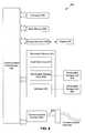
- FIG. 3illustrates a control server
- FIG. 4Aillustrates a positioning mechanism for a control system.
- FIG. 4Billustrates another positioning mechanism for a control system.
- FIG. 5illustrates a flow diagram for tracking and/or monitoring system components.
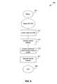
- FIG. 6illustrates a flow diagram for commanding and/or controlling system components in response to user location.
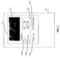
- FIG. 7illustrates a user interface for presenting control options.
- FIG. 8is an example computer system useful for implementing the present invention.
- FIG. 9illustrates a flow diagram for defining a control macro to watch a movie recording.
- FIG. 10illustrates a flow diagram for activating the control macro of FIG. 9 .
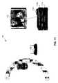
- FIG. 11illustrates another control system.
- FIG. 12illustrates another control system.
- FIG. 13illustrates another control system.
- FIG. 14illustrates a cradle for a controller client.
- FIG. 15illustrates another cradle for a controller client.
- FIG. 16illustrates another cradle for a controller client.
- FIG. 17Aillustrates another cradle for a controller client.
- FIG. 17Billustrates another cradle for a controller client.
- FIG. 18illustrates another cradle for a controller client, and a controller client.
- FIG. 19illustrates another cradle for a controller client.
- FIG. 20illustrates an EPG interface
- FIG. 21illustrates a flow diagram for presenting programming information.
- FIG. 22illustrates an EPG interface with a timer graphic.
- FIG. 23illustrates another timer graphic.
- FIG. 24illustrates a quick-view object.
- FIG. 25illustrates a jump-to-guide window
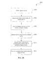
- FIG. 26depicts a flowchart of a method for legacy device virtualization.
- the present inventionincludes methodologies and/or techniques for the centralized command and control of a plurality of devices and/or applications within a controlled environment, such as a home, business, school, etc. Therefore in embodiments of the present invention, the controlled environment is a residential environment.
- the residential environmentpertains to the confines of a home, apartment, mobile home, houseboat, or other types of residences. However in embodiments, the residential environment includes the surrounding area of the residence, as well as any shelters, constructs, improvements, or the like, within a designated perimeter.
- the present inventionis implemented in non-residential environments.
- a non-residential environmentincludes, but is not limited to, an office complex, suite of small offices, production studio, warehouse, entertainment arena, health care facility, hotel, vacation resort, aircraft, ship, automobile, or the like.
- the controlled environment for the non-residential embodimentsinclude not only the actual confines of the aforementioned structures but also their surroundings within a designated perimeter.
- one or more computer servers, or the likeprovide a centralized command and control center for distributing information (including video, audio, voice, text, graphics, control messages, etc.) to the other devices and/or applications.
- Such devices and/or applicationsinclude communications equipment (such as, telephones, intercoms, etc.), entertainment systems (such as, televisions, CD/DVD players, gaming applications, stereos, etc.), monitoring systems (such as, security cameras, baby monitors, etc.), safety/security systems (such as, fire alarms, sprinkler systems, locks on doors or windows, etc.), personal computers (such as, desktops, notebooks, notepads, personal digital assistants, etc.), cooking appliances (such as, ovens, coffee makers, electrical food/beverage warmers, etc.), comfort systems (such as, heating and air conditioning, humidifiers, dehumidifiers, air purifiers, light switches, light dimmers, etc.), power outlets, power supplies, or the like.
- communications equipmentsuch as, telephones, intercoms, etc.
- entertainment systems
- a portable devicesuch as a digital personal assistant, wireless notepad, etc.
- a userenables a user to interact with the centralized command and control center. Such interaction includes altering the configuration and performance of the other devices and/or applications within the controlled environment. Accordingly, the portable device provides remote access to other devices and/or applications, and enables the user to control their functions and/or operations from any location within the controlled environment.
- a usercan operate the portable device to receive a recorded or live video from any location within the controlled environment.
- the videocan be presented on a display coupled to the portable device or a monitor within the area that the user is presently located. Accordingly, the user would be able to watch a television program while lounging near a swimming pool or in a whirlpool bath. Additionally, the user would be able to view video from a baby monitor or a security camera on the portable display device or another display, such as a wireless notepad, desktop computer, television screen, etc.
- a useris able to view or listen to media being presented on other televisions, personal computers, and/or audio systems.
- a “parent” usercan monitor television programs, web sites, and/or audio recordings that are being viewed by their children in other rooms.
- the present inventionincludes protocols that enable the parent user to block access to objectionable content.
- a useris able to access the centralized command and control center through an external interface, such as the Internet.
- a useris able to gain access to devices and/or applications that are located within the controlled environment, while the user is travelling or at work. Therefore, the present invention permits a user to log into the controlled environment to download or store files, receive feeds from surveillance equipment, open or secure locks on entry ways, or the like.
- the present inventioncan be implemented in residential and/or non-residential controlled environments.
- the following embodimentsare described with reference to a residential environment.
- the following embodimentscould be modified to include non-residential environments as well.
- FIG. 1illustrates a network control system 100 according to an embodiment of the present invention.
- System 100is a scaleable, relatively inexpensive, and versatile residential network.
- system 100includes a communications network 180 that interconnects a plurality of system components.
- the system componentsinclude a telephone 102 , a positioning unit 104 , a computer client 106 , a camera 108 , a controller client 110 , a television 112 , a control server 114 , a monitor 116 , an audio client 118 , and a residential appliance 120 .
- Other devices and/or applicationscan also be included as a system component.
- Control server 114manages the distribution of information among the other system components. As described in greater detail below, control server 114 interacts with the other components to directly or indirectly distribute data (including audio and/or video), voice, and/or control messages over communications network 180 . In an embodiment, control server 114 commands and controls the operation and/or functions of one or more of the other system components.
- Telephone 102is one or more wired and/or wireless telecommunications devices. Telephone 102 exchanges telecommunications signals over conventional residential telephone paths and communications network 180 .
- telephone 102implements a voice over Internet Protocol (VoIP) to exchange voice communications over a computer network (such as the global Internet), and makes the voice signals available to communications network 180 .
- VoIPvoice over Internet Protocol
- telephone 102includes facsimile functions.
- Positioning unit 104designates spatial locations within the residence that serves as the hosting environment for system 100 .
- Positioning unit 104is coupled to the other system components (e.g., control server 114 ) via a wired and/or wireless interface.
- Positioning unit 104is operable to designate a floor or room within the residence.
- Positioning unit 104is also operable to designate a specific location within a floor or room.
- positioning unit 104can be situated outside of the residence to thereby, designate external areas of the residence.
- positioning unit 104is coupled to another system component.
- multiple positioning units 104are distributed throughout the residence.
- the positioning units 104can be located within, or mounted to, a wall, door, ceiling, floor, etc. Positioning unit 104 is further described below.
- Computer client 106includes a wired and/or wireless personal computer, personal digital assistant (PDA), enhanced telephone, personal television, or other data processing device linked to communications network 180 .
- PDApersonal digital assistant
- computer client 106can be a desktop, notebook, notepad, or the like.
- a displayis coupled to computer client 106 to provide a text or graphical user interface (GUI) and enable a user to interactively communicate with control server 114 .
- Input devices for computer client 106include a keyboard, mouse, verbal command interface, mouse wheel, joystick, rudder pedals, touch screen, microphone, joystick, stylus, light pen, or any other type of peripheral unit.
- Camera 108is one or more video cameras, camcorders, or the like. The present invention contemplates both wired and wireless devices. Camera 108 can be a part of home security or monitoring system, such as a baby monitor, etc. In an embodiment, camera 108 includes a control unit that enables remote control of various camera functions, such as, pan, tilt, zoom, focus, iris control, etc.
- Controller client 110is a wired and/or wireless data processing device that enables a user to interact and send control messages to control server 114 and the other system components.
- Controller client 110can be a portable or non-portable version of the devices listed as computer client 106 .
- computer client 106can be a personal notebook or notepad computer, PDA, enhanced telephone, or other device linked to communications network 180 and including a display with the ability to interact with the other system components.
- controller client 110enables a user to remotely control the operations of various components of system 100 .
- the display for controller client 110is capable of receiving video and/or audio from the other system components.
- controller client 110includes a flash ROM that enables wireless downloads and/or uploads.
- Television 112can be a conventional television.
- television 112is enhanced to support interactive and/or personal services.
- Personal servicesinclude virtual recording, programming, pausing/rewinding live broadcasts, or the like.
- television 112can be a personal television enhanced to support the MSN® TV service, hosted by WebTV Networks, Inc. (Mountain View, Calif.), that supports WebTV® available from Microsoft Corporation (Redmond, Wash.).
- television 112includes a set-top box for cable and/or satellite receptions.
- television 112is connected to a PVR, VCR, or DVD player.
- Monitor 116is a wired or wireless display that supports closed-circuit viewing.
- monitor 116is a flat LCD positioned on a wall, standing on a desk, table, or counter top, situated near the side of pool or hot tub, etc.
- monitor 116receives a streaming screen saver that displays static or dynamic images of a photograph, portrait, etc. when monitor 116 is functioning in an inactive state.
- monitor 116receives feeds from a television, stereo, or security/monitoring system (e.g., a baby monitor), etc., when monitor 116 is in an active state.
- a television, stereo, or security/monitoring systeme.g., a baby monitor
- Audio client 118is a wired or wireless audio system, such as a stereo, audio server, CD/record/cassette player, MP3 player, etc. Audio client 118 can be a microphone as part of a security/monitoring system, such as a baby monitor. In an embodiment, audio client 118 is one or more speakers or like audio outputs located throughout the residence. In another embodiment, audio client 118 is an intercom system, public announcement system, door answering service, or the like.
- Residential appliance 120is one or more residential appliances, such as, but not limited to, a refrigerator, stove, microwave, toaster, coffee-maker, alarm clock, thermostats, humidifiers, sprinkler system, lighting, light dimmers, etc.
- control server 114 and/or controller client 110controls the operations and/or functions of one or more residential appliances 120 , such as on/off, timers, modulation (e.g., oven temperatures, etc.), pause, snooze, etc.
- communications network 180provides a transmission medium for communicating among the system components.
- control server 114polices traffic among the other system components.
- the exchange of information among the system componentsis routed or otherwise controlled via control server 114 .
- communications network 180supports peer-to-peer communications.
- the system componentsexchange audio, video, other data, and/or control messages directly with each other and without being centrally managed by control server 114 . Therefore, the present invention can be implemented without control server 114 .
- the control and management functions for the communications network 180are distributed and shared by multiple system components so that the system components can communicate with each other over a wired and/or wireless medium without a central control server 114 .
- Communications network 180is a wired and/or wireless local area network (LAN).
- communications network 180includes wired, wireless, or both transmission media, including satellite, terrestrial (e.g., fiber optic, copper, UTP, STP, coaxial, hybrid fiber-coaxial (HFC), or the like), radio, microwave, free-space optics, and/or any other form or method of transmission.
- satellitee.g., fiber optic, copper, UTP, STP, coaxial, hybrid fiber-coaxial (HFC), or the like
- radiomicrowave, free-space optics, and/or any other form or method of transmission.
- communications network 180is an Ethernet LAN capable of supporting, for example, one hundred Mbps to one Gbps.
- a CAT-5 cableor the like, is coupled to control server 114 and is distributed to a location within each room.
- the cableis distributed to each system component, such as television 112 , monitor 116 , etc.
- the system componentincludes an audio/video (AV) connector that is responsive to receive the cable.
- AVaudio/video
- communications network 180supports the IEEE standard 802.11(a) which specifies a wireless Ethernet protocol for large-sized video. Using this protocol, communications network 180 can handle up to fifty-four Mbps with an effective range of ninety feet.
- communications network 180supports the IEEE standard 802.11(b) which specifies a wireless Ethernet protocol for small-size video. With this wireless protocol, communications network 180 is effective for ranges approximating 150-300 feet, and capable of supporting a nominal bandwidth of eleven Mbps, with 4-5 Mbps effective bandwidth.
- communications network 180supports the IEEE 802.16 WirelessMAN® standard for wireless metropolitan area networks.
- the BluetoothTM wireless technology(developed by Bluetooth SIG, Inc.) is used to support short-range wireless interfaces with system 100 .
- communications network 180includes a telephone line and/or powerline.
- communications network 180enables conventional electrical outlets and wiring to interconnect the system components and enable them to communicate with each other.
- communications network 180includes communications technologies made available from the Home Phone Networking Alliance (HomePNA) or the like.
- HomePNA technologiesenable the operation of telephone services and home networking, including, but not limited to, video conferencing, video security, VoIP telephony, digital video networking, internet sharing, and multi-user gaming.
- communications network 180includes a central control server 114 to enable the system components to communicate with each other.
- any platform that is relatively small in physical size, has access to power lines for continuous and uninterrupted electrical power, and is physically located to facilitate transmission and reception of wireless signalsis suitable for providing housing, hosting, or the like for central control server 114 .
- FIG. 11illustrates an embodiment of network control system 100 that includes a wireless network access point 1180 , such as those available from Linksys Group Inc. (Irvine, Calif.) or Cisco Systems, Inc. (San Jose, Calif.), as a platform for control server 114 .
- Wireless access point 1180provides control server 114 ( FIG. 1 ) with a central point for connectivity in a wireless network and always-on connectivity necessary for tracking states of the system components. Additionally, wireless access point 1180 can provide a connection point between a wired and wireless network.
- the system componentsinclude controller client 110 , television 112 , a media player 1112 , and a cable box 1108 .
- Other system components having external control interfacescan be included, such as telephone 102 , positioning unit 104 , computer client 106 , camera 108 , control server 114 , monitor 116 , audio client 118 , residential appliance 120 , and the like.
- the network illustrated in FIG. 11also includes an infrared/serial bridge 1182 .
- infrared/serial bridge 1182complies with the IEEE 802.11(b) standard for wireless communications.
- Infrared/serial bridge 1182exchanges infrared signals with stand-alone system components, such as television 112 , cable box 1108 , and media player 1112 .
- FIG. 12illustrates another embodiment of network control system 100 , which includes a plurality of infrared/serial bridges 1182 ( a )- 1182 ( e ).
- Other devices in the network control system 100may not require an infrared/serial bridge.
- computer client 106 ( a ) operating Microsoft XP Media Center EditionTMowned by Microsoft® Corporation
- computer client 106 ( b ) operating Microsoft Windows XPTMowned by Microsoft Corporation
- Each infrared/serial bridge 1182 ( a )- 1182 ( e )interacts with one or more stand-alone components.
- infrared/serial bridge 1182 ( a )interacts with television 112 ( a ), cable box 1108 , and media player 1112 .
- Infrared/serial bridge 1182 ( b )interacts with a tuner 1104 or any type of proprietary Ethernet device as would be apparent to one skilled in the relevant art(s).
- Infrared/serial bridge 1182 ( c )interacts with a residential appliance 120 ( a ), namely a thermostat for a HVAC system.
- Infrared/serial bridge 1182 ( d )interacts with another residential appliance 120 ( b ), namely a lamp using LutronTM (owned by Lutron electronics Co., Inc.) or X10TM (owned by X10 Ltd. Corporation) protocols.
- Infrared/serial bridge 1182 ( e )interacts with television 112 ( b ) and a DSS box 1106 .
- the present inventioncan integrate legacy devices (e.g., consumer electronic devices that rely on infrared/serial communication protocols), as well as UPnPTM (owned by UPnP Forum) devices and applications defined by the Universal Plug and Play (UPnP) ForumTM (owned by UPnP Forum), as system components.
- legacy devicese.g., consumer electronic devices that rely on infrared/serial communication protocols
- UPnPTMowned by UPnP Forum
- UUPnPUniversal Plug and Play
- UPnP ForumTMowned by UPnP Forum
- An example of a controlled environment implementing an IEEE 802.11(b) infrared/serial bridgeis described in the application entitled “Legacy Device Bridge for Residential or Non-Residential Networks” (U.S. Patent App. Ser. No. 60/438,296; filed Jan. 7, 2003), which is incorporated herein by reference as though set forth in its entirety.
- a legacy device bridge in accordance with an embodiment of the present inventionis configured to prevent communication between the legacy device bridge and more than one control server. This could occur, for example, where multiple control servers are sharing, either advertently or inadvertently, a wireless network (for example, in a WLAN, they share the same SSID (Service Set Identifier)). Such an overlap may expose a network-controlled environment to undesired outside control, such as control by a neighbor.
- SSIDService Set Identifier
- the legacy device bridgeavoids this problem by storing the network address of the first control server that contacts the bridge after it is connected to the network. Then, future incoming packets received from any other address are discarded.
- the address of the control serveris configured out-of-band. For example, the address of the control server may be provided to the legacy device bridge using IR or serial communication with a corresponding IR or serial interface. After the address has been so configured, incoming packets received from any other address are discarded.
- the legacy device bridgeis adapted to act as a room controller.
- the legacy device bridgeis adapted as follows: (1) the legacy device bridge is adapted to automatically configure itself in most home networking environments, although some cases may require direct user intervention in order to configure the bridge; (2) to facilitate ease of use, the legacy device bridge is adapted for IrDA out-of-band configuration, e.g., the legacy device bridge can be programmed to accept network configuration parameters from an IR port using industry-standard data transmission protocols; and (3) the legacy device bridge is adapted to learn new legacy device codes, such as IR or serial control codes. For example, although a sizable body of IR codes exist in commercial databases, the broad range of available consumer electronic devices make claims of absolute compatibility difficult.
- a legacy device bridgein accordance with an embodiment of the present invention is adapted to be placed in a state where it can receive and store new IR or serial control codes.
- the IR or serial control codesmay be transmitted by another device, such as an IR remote control device.
- the legacy device bridgemay store learned codes internally or upload them to a server on the network for storage.
- FIG. 26depicts a flowchart 2600 of a method for legacy device virtualization, advertisement and control in accordance with an embodiment of the present invention.
- a virtualization appliancedetects a legacy device, such as a consumer electronic device, that it will control. By detecting legacy devices, the virtualization appliance builds a list of legacy devices under its control.
- the virtualization applianceis made aware of a legacy devices through manual programming of the virtualization appliance by a user.
- the virtualization appliancedetects a legacy device through an automatic process, such as two-way IR queries between the virtualization appliance and a legacy device.
- the virtualization applianceacquires and stores control codes for the legacy device.
- control codesare obtained through manual programming of the virtualization appliance by a user.
- the virtualization applianceobtains the control codes through an automatic process, such as two-way IR queries between the virtualization appliance and a legacy device.
- the virtualization applianceadvertises the legacy device to the network as a UPnP device possessing attributes and controls similar to the legacy device it is masquerading for.
- this stepincludes publishing a list of standard UPnP commands for controlling the legacy device, wherein the published UpnP commands correspond to one or more of the low-level legacy device codes acquired in step 2604 .
- entities on the networkperceive the virtualization appliance as a piece of IP-addressable and controllable consumer electronics.
- a network entitytransmits a standard UPnP command, such as “Power On” or “Power Off”, to control the legacy device, and this UPnP command is received by the virtualization appliance.
- the virtualization applianceconverts the UPnP command to a corresponding control code for the legacy device, and at step 2612 , the virtualization appliance transmits the corresponding control code to the legacy device.
- the virtualization applianceacts as a transparent proxy between network entities and the legacy device.
- FIG. 13illustrates another embodiment of network control system 100 , which includes a smoke detector 1380 .
- Smoke detector 1380includes a network interface card 1382 which enables smoke detector 1380 to serve as yet another platform for control server 114 , providing the control server with HomePNA and/or wireless (e.g., IEEE 802.11) network connectivity.
- the control servercan send data and/or control messages throughout the controlled environment either through a wireless connection or through the power line. Since most smoke detectors are presently hard-wired into the home or office power line, the smoke detector platform also provides always-on connectivity for control server 114 .
- Another advantage of using a smoke detector as a platform for control server 114is that smoke detectors can be ceiling mounted to facilitate a greater communications range.
- FIG. 14illustrates another device that can be used as a platform for control server 114 .
- the device shownis a cradle 1400 for a remote control unit, such as controller client 110 , or another system component.
- Alternative views of cradle 1400are illustrated in FIG. 15 and FIG. 16 .
- Cradle 1400contains a receptacle 1402 for holding the remote control unit or other device.
- Receptacle 1402provides an integrated charging base for the remote control or other device.
- Power supply port 1404supplies power to the remote control when it is docked in receptacle 1402 . Power from power supply port 1404 is converted to DC power.
- Power supply port 1404also provides connectivity with a HomePNA/powerline network.
- Cradle 1400also includes an Ethernet interface 1406 for enabling network connectivity. Additionally, cradle 1400 has a wireless interface for enabling wireless network connectivity, such as WiFi (i.e., IEEE standard 802.11(a) or (b)). Cradle 1400 also has an IR interface 1410 to communicate via IR signals. Cradle 1400 may have other transmission and data ports (e.g., serial (RS-232) or USB) and network interfaces (e.g., HomePNA/powerline). Such connectivity enables cradle 1400 to serve as a bridge for converting packet-based data signals (e.g., WiFi) to IR or serial signals. Cradle 1400 includes LED indicators indicating power 1408 and network-connectivity status 1412 of the cradle.
- WiFii.e., IEEE standard 802.11(a) or (b)
- Cradle 1400also has an IR interface 1410 to communicate via IR signals.
- Cradle 1400may have other transmission and data ports (e.g.,
- FIG. 19depicts a cradle in accordance with an embodiment of the present invention.
- cradle 1400includes a wireless interface 1902 (such as an 802.11b transceiver) for providing wireless connectivity to an IP network.
- Cradle 1400includes an IrDATM (owned by Infrared Data Association Corporation) beacon 1908 as an interface for communicating with IR-enabled legacy devices.
- Cradle 1400contains one or more infrared interfaces 1904 for communicating with IR-enabled legacy devices.
- Cradle 1400contains one or more serial interfaces 1906 for communicating with serial-enabled legacy devices.
- Cradle 1400includes a power supply interface 1910 for communicating via a HomePNA/powerline network.
- IR interface 1410can include IRDA beacon 1908 .
- IR interface 1410comprises an IR transmitter adapted for wireless one-way communication with IR-capable legacy devices.
- IR interface 1410comprises an IR transmitter/receiver pair, or IR transceiver, adapted for wireless two-way communication with IR-capable legacy devices.
- wireless IR communication with a legacy deviceis achieved by cradle 1400 in a location that is along a clear line-of-sight path to and within a certain predefined transmission range of the legacy device.
- IR interface 1904comprises an interface adapted for wired communication with a legacy device by means of, for example, an IR dongle.
- the cradle 1400need not be situated in any particular location for effective communication with the legacy device.
- Smoke detector 1380 , wireless network access point 1180 , and cradle 1400are representative devices that can be used as platforms for control server 114 .
- any other deviceincluding, but not limited to, a stand alone computer, remote control device, power device (including power strip, power conditioner, power outlet, power supply, etc.), set-top box, cable box, router, bridge, or the like, could be included and would not change the scope of the invention.
- Any presently available or future developed devicecan be used that has “always-on” functionality (i.e., access to continuous and uninterrupted electrical power) and is positioned to facilitate wireless communications with the other system components.
- Such devicescan include, or be modified to receive, a network interface card (e.g., network interface card 1382 ) to enable platform functionality.
- a network interface carde.g., network interface card 1382
- wireless network access point 1180can be hosted on any type of “always-on” platform having wireless or wired network connectivity (such as, a smoke detector, ceiling fan, etc.). As such, the platform would provide wireless access point (WAP) functionality in addition to and without interfering with its traditional functionality.
- WAPwireless access point
- an access pointe.g., wireless network access point 1180
- wireless network access point 1180can be mounted in tandem with the smoke detector. The two can be packaged into the same plastic housing.
- a wireless access pointgenerally requires an Ethernet connection to bridge it to a wired Ethernet network (which, in turn, may be connected to a cable or DSL modem).
- the wireless access pointmay be used in a repeater mode, extending the range of another wireless access point that has an Ethernet connection (see, for example, signal repeater 1202 , described herein with reference to FIG. 12 ).
- Smoke detector 1380is a representative device that can be used as a platform for wireless network access point 1180 .
- WAP functionalitycan be integrated into any other device connected to a power source, including, but not limited to, a ceiling fan, light fixture, wall switch, carbon dioxide detector, wall outlet, or the like.
- a powerline bridge and wireless access pointcan be integrated together, avoiding the need to operate solely in repeater mode.
- Control server 114is one or more servers, with each server being one or more computers providing various shared resources with each other and to other system components.
- the shared resourcesinclude files for programs, web pages, databases and libraries; output devices, such as, printers, plotters, display monitors and facsimile machines; communications devices, such as modems and Internet access facilities; and other peripherals such as scanners, etc.
- the communications devicescan support wired or wireless communications, including satellite, terrestrial (fiber optic, copper, coaxial, and the like), radio, microwave, free-space optics, and/or any other form or method of transmission.
- control server 114is configured to support the standard Internet Protocol (IP) developed to govern communications over public and private Internet backbones.
- IPInternet Protocol
- the protocolis defined in Internet Standard (STD) 5, Request for Comments (RFC) 791 (Internet Architecture Board).
- Control server 114also supports transport protocols, such as, Transmission Control Protocol (TCP), User Datagram Protocol (UDP), Real Time Transport Protocol (RTP), or Resource Reservation Protocol (RSVP).
- TCPTransmission Control Protocol
- UDPUser Datagram Protocol
- RTPReal Time Transport Protocol
- RSVPResource Reservation Protocol
- the transport protocolssupport various types of data transmission standards, such as File Transfer Protocol (FTP), Hypertext Transfer Protocol (HTTP), Simple Network Management Protocol (SNMP), Network Time Protocol (NTP), or the like.
- FTPFile Transfer Protocol
- HTTPHypertext Transfer Protocol
- SNMPSimple Network Management Protocol
- NTPNetwork Time Protocol
- control server 114is configured to support various operating systems, such as, the NetwareTM operating system available from Novell, Inc. (Provo, Utah); the MS-DOS® and Windows® operating systems available from Microsoft Corporation; the Linux® operating system available from Linux Online Inc. (Laurel, Md.); the SolarisTM operating system available from Sun Microsystems, Inc. (Palo Alto, Calif.); or the like as would be apparent to one skilled in the relevant art(s).
- operating systemssuch as, the NetwareTM operating system available from Novell, Inc. (Provo, Utah); the MS-DOS® and Windows® operating systems available from Microsoft Corporation; the Linux® operating system available from Linux Online Inc. (Laurel, Md.); the SolarisTM operating system available from Sun Microsystems, Inc. (Palo Alto, Calif.); or the like as would be apparent to one skilled in the relevant art(s).
- Control server 114is operable to query, receive, and/or write to various archival and/or retrieval components.
- the archival and/or retrieval componentscan be internal and/or external to control server 114 .
- control server 114is configured to receive compressed streams, filter the streams for metadata (such as, date, time, source, etc.), and store the streams and metadata for future retrieval.
- FIG. 2shows control server 114 connected to various archival and/or retrieval (A/R) components according to an embodiment of the present invention.
- the A/R componentsinclude a media archive 202 , a tuner 204 , a DSS box 206 , a cable box 208 , a media changer 210 , and a media player 212 .
- the aforementioned archival and/or retrieval componentsare not intended to be an exhaustive listing. Other archival and/or retrieval components can be implemented and are deemed to be within the scope of the present invention.
- Network connection 280includes a wired and/or wireless LAN or wide area network (WAN), such as an organization's intranet, a local internet, the global-based Internet (including the World Wide Web (WWW)), an extranet, a virtual private network, licensed wireless telecommunications spectrum for digital cell (including CDMA, TDMA, GSM, EDGE, GPRS, CDMA2000, WCDMA FDD and/or TDD or TD-SCDMA technologies), or the like.
- WANwide area network
- Network connection 280includes wired, wireless, or both transmission media, including satellite, terrestrial (e.g., fiber optic, copper, UTP, STP, coaxial, hybrid fiber-coaxial (HFC), or the like), radio, free-space optics, microwave, and/or any other form or method of transmission.
- satellitee.g., fiber optic, copper, UTP, STP, coaxial, hybrid fiber-coaxial (HFC), or the like
- radiofree-space optics, microwave, and/or any other form or method of transmission.
- Media archive 202provides one or more storage mediums for various data (including video and audio) and metadata.
- media archive 202includes a removable storage unit (e.g., floppy disk, CD-ROM, etc.), as described in greater detail below.
- a removable storage unite.g., floppy disk, CD-ROM, etc.
- one or more integrated databases or a data warehouse systemis used to store the content and support control server 114 , as described herein.
- media archive 202includes a relational or object oriented (OO)/component based database management system, or the like, that controls the storing, retrieving, and updating of data and metadata in the database records.
- the database management systemalso controls data integration, enforces integrity rules and constraints (including data integrity and referential integrity), and enforces security constraints.
- media archive 202is a scalable system that stores data on multiple disk arrays. Data warehousing can be implemented with the SQL Server 2000 application available from Microsoft Corporation, the Oracle 9iTM database available from Oracle Corporation (Redwood City, Calif.), or the like. In embodiments, media archive 202 supports Open DataBase Connectivity (ODBC) or Java DataBase Connectivity (JDBC) protocols.
- ODBCOpen DataBase Connectivity
- JDBCJava DataBase Connectivity
- media archive 202is an index file database system or a plan file database system, such as the Berkeley DB database resources available from Sleepycat Software, Inc. (Lincoln, Mass.).
- Tuner 204receives audio and/or video signals from television and/or radio broadcasts.
- Tuner 204is one or more individual radio and/or television tuners.
- tuner 204is configured to receive NTSC/PAL television signals.
- DSS box 206receives audio and/or video broadcast signals from a satellite receiver.
- Cable box 204receives audio and/or video broadcasts and pay-for-view unicasts over a copper, UTP, STP, coaxial, optic or HFC interface.
- control server 114is also configurable to support recording capabilities. As discussed, broadcast can be recorded to media archive 202 . However, control server 114 includes one or more record/playback applications or devices, namely media player 212 and media changer 210 .
- Media player 212can be a VCR player, DVD player, PVR, video server, virtual recorder, audio server, stereo, CD player, record player, audio tape or cassette player, digital audio tape recorder, and/or any other device or application that stores, records, generates, or plays back via magnetic, optical, electronic, or any other storage media.
- the recordingscan be indexed by album, song, artist, genres, or the like.
- Media changer 210records and plays media and/or multimedia similar to media player 212 .
- media changer 210is capable of loading multiple recordings (e.g., CD, DVD, etc.) to be played without having to be reloaded.
- media changer 210can be a jukebox or like device that enables a user to load all available CDs, for example, at once.
- Control server 114provides centralized command and control of various functions within a controlled environment, such as system 100 .
- the functions managed by control server 114includes video serving, audio serving, telephony, messaging, file sharing, Internet access, and security.
- a useroperates controller client 110 to establish or re-configure these functions and/or receive media from control server 114 or other system components (either directly from the other system components or indirectly from the system components via control server 114 ).
- FIG. 3illustrates an embodiment of control server 114 .
- Control server 114includes various controller modules for managing various system functions. As shown, control server 114 includes a video controller 302 , an audio controller 304 , a telephony controller 306 , a messaging controller 308 , a file sharing controller 310 , an external network interface (x-interface) controller 312 , and a security controller 314 .
- the controller modulesare configured to exchange signals with other system components via communications network.
- the controller modulesare also configured to exchange communications with other A/R components. As described with reference with FIG. 2 , the A/R components include media archive 202 , tuner 204 , DSS box 206 , cable box 208 , media changer 210 , media player 212 , and/or the like.
- Video controller 302manages the exchange of video signals within system 100 .
- Video controller 302receives and/or distributes video signals for displays coupled to, for example, computer client 106 , television 112 , monitor 116 , controller client 110 , etc.
- Video controller 302also interacts with the A/R components, such as, media archive 202 , tuner 204 , DSS box 206 , cable box 208 , media changer 210 , media player 212 , network connection 280 , etc.
- video controller 302reads and/or writes to an internal storage medium that is designated for video, and that is in addition to, or in lieu of, the A/R components of the present invention.
- video controller 302receives video signals from the AIR components (and/or its internal storage medium) and distributes them to other system components (e.g., television 112 , controller client 110 , etc.).
- Video controller 302can also receive a video stream from a source (e.g., network connection 280 , television 112 , media archive 202 , etc.) and store the stream in one of the A/R components (e.g., media archive 202 , media player 212 , etc.), and/or its internal storage medium, for future viewing.
- video controller 302can query a web site (e.g., “www.mtv.com”) to download a music video to be played and/or stored to a system component.
- a web sitee.g., “www.mtv.com”
- video controller 302provides MPEG encoding on the fly according to embodiments of the present invention.
- video controller 302is able to receive, encode, and distribute a media stream in real time or near term.
- network connection 280enables video controller 302 , or like components, to implement broadband internet access for audio/video distribution.
- Audio controller 304manages the exchange of audio signals within system 100 . Accordingly, audio controller 304 receives and/or distributes audio signals for one or more audio components, such as, for example, audio client 118 or speakers coupled to, for example, computer client 106 , television 112 , monitor 116 , controller client 110 , etc. Audio controller 304 also interacts with the A/R components (e.g., tuner 204 , DSS box 206 , cable box 208 , media changer 210 , media player 212 , network connection 280 , etc.) to receive audio signals from the A/R components and distribute them to other system components (e.g., audio client 118 , controller client 110 , etc.).
- A/R componentse.g., tuner 204 , DSS box 206 , cable box 208 , media changer 210 , media player 212 , network connection 280 , etc.
- audio controller 304can receive an audio stream from a source (e.g., network connection 280 , television 112 , media archive 202 , etc.) and store the stream in one of the A/R components (e.g., media archive 202 , media player 212 , etc.) for future recall.
- audio controller 304reads and/or writes to an internal storage medium that is designated for audio, and hence distributes audio to and from its internal storage medium.
- audio controller 304can query a web site (e.g., “MP3.com”) to download a digital recording to be played and/or stored to a system component.
- audio controller 304encodes the audio stream to MPEG-3 format to produce near-CD quality in real time or near time.
- audio controller 304encodes the audio stream to produce CD quality audio in real time or near term.
- Telephony controller 306is another controller module within control server 114 . Telephony controller 306 manages the distribution of telecommunications from conventional telephone paths and/or computer networks (e.g., communications network 180 , network connection 280 , etc.).
- telephone 102is coupled to a conventional wired or wireless telephone path (not shown), such as POTS or PSTN. Telephone 102 can also be coupled to a cellular or satellite communications path (not shown).
- a dedicated interface(not shown) is provided to enable the cellular/satellite telephone 102 to interact with system 100 . Calls received or transmitted over the conventional path are also monitored and/or controlled by control server 114 .
- control server 114is responsive to distributing signals from the calls to other system components.
- controller client 110is one potential recipient component. Hence, a user is able to directly operate controller client 110 to place and/or receive calls indirectly via telephone 102 .
- telephone 102is coupled to a computer network.
- a wired or wireless telephone(not shown) that is coupled to computer client 106 is capable of interacting with a computer network.
- the computer networkis a LAN or WAN (such as the Internet) that is accessed via communications network 108 or network connection 208 , or the system components (i.e., telephone 102 , computer client 106 ) can have a dedicated link to a computer network, such that the link is independent of communications network 180 .
- the telecommunications signalsare formatted for VoIP or the like. Irrespective of the source of the computer network, the telecommunications signals from the computer network are monitored and/or controlled by control server 114 . As discussed with reference to conventional telecommunications calls, control server 114 is responsive to distributing signals from the calls to other system components, such as, for example, controller client 110 .
- control server 114is operable to perform other telephony functions.
- control server 114supports speed dialing.
- Telephone numbersare stored in a memory (such as one of the A/R components described with reference to FIG. 2 ) coupled to residential control server 114 .
- control server 114is programmable to implement service blocking. A user is able to create a profile to block telephone calls from a designated number or family or numbers (e.g., 900 calls, etc.).
- control server 114logs inbound/outbound calls and/or enable redialing of past and/or missed calls.
- Control server 114also includes messaging controller 308 .
- Messaging controller 308enables centralized storage of telephone calls received via telephony controller 306 and the like. Voice messages are written to a memory (such as one of the A/R components described with reference to FIG. 2 ) coupled to control server 114 .
- Messaging controller 308also permits messages (including audio, video, and/or text) to be created, stored, and/or retrieved within system 100 .
- a usercan operate one of the system components (e.g., controller client 110 , telephone 102 , audio client 118 , etc.) to create a message for the same or another user. The message can be a “to-do” list, baby-sitting instructions, grocery list, etc.
- Messaging controller 308also enables control server 114 to interact with computer client 106 or other system components to search and/or retrieve data from computer emails, instant messaging services, and/or notes, tasks, reminders, and/or events from personal calendars.
- Control server 114also includes file sharing controller 310 .
- File sharing controller 310enables control server 114 to function as a central file server for all personal computers in communications with system 100 .
- File sharing controller 310permits files to be stored and accessed by system components located within the residence that is hosting system 100 .
- devices located outside of system 100are able to store and/or retrieve files via file sharing controller 310 . For example, if a static IP address is sustained by the ISP for system 100 , a remote user could log into control server 114 to retrieve and/or store files via file sharing controller 310 .
- X-interface controller 312is another controller module of control server 114 .
- X-interface controller 312manages access to the system components from external devices and/or applications, and/or access to external devices, applications, and/or web sites from the system components.
- x-interface controller 312provides a gateway to external networks, such as the global Internet, other private WANs, or the like.
- x-interface controller 312supports web proxies and is configurable to block designated web sites in toto or per user.
- x-interface controlleris operable to track and/or record access/visits to web sites from other system components.
- X-interface controller 312supports wired and/or wireless access to external networks, including cable and/or satellite ISPs.
- x-interface controller 312permits control server 114 to operate as a web server, provided the ISP is able to provide a static IP address.
- Security controller 314enables control server 114 to interact with and/or manage various security systems, including the communications security protocols for system 100 .
- security controller 314controls and/or monitors feedback from system components that form a part of a security system. For example, video (e.g., camera 108 , etc.) and audio (audio client 118 , camera 108 , etc.) can be captured and served to controller client 110 or monitor 116 .
- Motion sensorscan also be placed within the residence or in external locations surrounding the residence. Feedback from the motion sensors can also be transmitted to security controller 314 . In an embodiment, such feedback activates cameras 108 and/or audio clients 118 within the vicinity. In another embodiment, such feedback activates an alarm or signals the user of controller client 110 .
- controller client 110can vibrate, ring, flash a message, or the like.
- Control systems coupled to camera 108permit security controller 314 to move and/or focus camera 108 .
- security controller 314is operable to lock or unlock doors, windows, or entryways in response to user input.
- security controller 314interfaces with fire and safety control system. As such, sensors feed into control server 114 and permit system 100 or a user to monitor emergency situations. Alarms, sprinkler systems, and the like can be operated via control server 114 and/or controller client 110 .
- security controller 314In addition to home access and fire and safety systems, security controller 314 also interacts with personal asset security systems, such as safes, file cabinets, rooms, drawers, and the like. Security profiles can be created and maintained to permit selected individuals to access secured areas. Passwords, biometrics, and/or the like can be stored and authenticated to permit access.
- Security controller 314also permits profiles to be established and maintained to monitor and/or restrict access to web sites, telephone numbers, television channels, CDs, videocassettes, or the like.
- user profilesare established to permit remote access to the system components from externally located devices and/or applications.
- an external usercan be authorized via security controller 314 to log into control server 114 over the Internet from a remote location and receive live feeds from camera 108 , archived feeds from camera 108 , broadcasts from television 112 , messages stored via messaging controller 308 , files stored via file sharing controller 310 , or the like.
- parentscould access control server 114 to monitor their home and/or their children or babysitter while away on vacation or at work.
- Control server 114is not limited to the functions depicted in FIG. 3 .
- Control server 114can include other modules for controlling the operations and functions of the various system components, including by mimicking a user's remote-control commands through on-screen menus.
- control server 114can set or synchronize a clock for one or more system components, including the A/R components.
- Control server 114includes a real-time clock that can be set by a user through a direct user interface with control server 114 or through another system component, such as controller client 110 .
- the real-time clockcan be set via the Internet (i.e., network connection 280 ).
- Control server 114uses its own real-time clock to set the clock of other system components by navigating the menu system of the respective system component. Since control server 114 tracks and monitors the state of the system components, control server 114 is programmable to navigate the menus of the system component to set the clock without interfering with the component's operations, such as when a movie is playing or recording.
- Instructions for navigating a system componentare stored in a database or similar library coupled to control server 114 .
- the input numbers for navigating the menus of, for example, a VCR or DVD player to set or program its internal clockcan be memorized.
- the memorized numbersare associated with a set of IR codes, which are stored at control server 114 .
- the IR codesare retrieved from the IR code database or library, and transmitted to the appropriate media player 212 .
- the IR codesare executed to navigate the menus to set the clock.
- IR codescan also be selected to program media player 212 to record select programs, and the like.
- control server 114keeps an updated electronic program guide in a database.
- the electronic program guide(EPG) can be displayed on controller client 110 or like system components for presentation to a user.
- Control server 114can obtain the electronic guide from an Internet service, such as GUIDE Plus+® available from Gemstar-TV Guide International, Inc. (Pasadena, Calif.).
- GUIDE Plus+®available from Gemstar-TV Guide International, Inc. (Pasadena, Calif.).
- a usercan operate controller client 110 to select channels based on the electronic guide data and/or select programs for recording from the electronic guide.
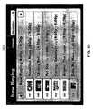
- FIG. 20illustrates an EPG interface 2000 that can be displayed on controller client 110 or another system component.
- EPG interface 2000includes a plurality of channel objects 2002 a - 2002 n , with each one representing a “favorite” programming channel as selected by a user.
- EPG interface 2000can be a touch-screen user interface, whereby a finger, stylus, or other device is used to select one of the channel objects 2002 a - 2002 n .
- voice recognition, a mouse, cursor arrows, or other pointing devices and/or user interfacescan be used.
- control server 114includes an EPG controller (operating as an integral or independent component of video controller 302 ) that manages the display of EPG interface 2000 and the channel objects 2002 a - 2002 n .
- EPG controlleroperating as an integral or independent component of video controller 302
- Each of the channel objects 2002 a - 2002 nare directly or indirectly linked to a switch and/or EPG information for a corresponding favorite channel (e.g., ArtsworldTM (owned by British Sky Broadcasting Group plc), BBC OneTM (owned by British Broadcasting Corporation), BravoTM (owned by NBC Universal Media, LLC), CNBCTM (owned by CNBC, Inc.), MTVTM (owned by Viacom International, Inc.), Cartoon NetworkTM (owned by Cartoon Network, Inc.), Animal PlanetTM (owned by Discovery Communications, Inc.), CNNTM (owned by Cable News Network, Inc.), DiscoveryTM (owned by Discovery Communications, Inc.), etc.).
- ArtsworldTMowned by British Sky Broadcasting Group plc
- BBC OneTMowned by British Broadcasting Corporation
- the activated channel object 2002 a - 2002 nenables a control message to be transmitted that either retrieves programming information for the corresponding channel or switches a selected device (e.g., television 112 , tuner 204 , DSS box 206 , cable box 208 , etc.) to the corresponding channel.
- a selected devicee.g., television 112 , tuner 204 , DSS box 206 , cable box 208 , etc.
- flowchart 2100shows an example of a control flow for presenting programming information on an EPG interface, such as EPG interface 2000 .
- the control flow of flowchart 2100begins at step 2102 and passes immediately to step 2104 .
- an activation signalis received from a user interface, such as touch screen or other input devices.
- a userpresses and holds one of the channel objects 2002 a - 2002 n to activate the channel object associate with the MTV programming channel.
- a timeris initiated at step 2106 .
- a clock signalcan be generated to increment a timer register that is initially set at zero.
- the timer valueis read from, for example, the register.
- a deactivation signalis generated.
- the control flowchecks for the deactivation signal. If found, the control flow passes immediately to step 2124 as described below. Otherwise, the control flow passes to step 2112 .
- step 2112the timer value from step 2108 is analyzed. If the timer value is less than two seconds, control passes to step 2114 .
- step 2114a timer graphic is displayed over the activated channel object 2002 a - 2002 n .
- FIG. 22illustrates an example of a timer graphic 2202 that is produced from the activation of a channel object 2002 a - 2002 n .
- Timer graphic 2202is a dynamic object having two concentric circles that are filled over time.
- FIG. 23illustrates another example of timer graphic 2202 with the two concentric circles.
- the concentric circlesinclude a quick-view circle 2304 and a jump-to-guide circle 2306 .
- Quick-view circle 2304is linked to a quick-view timer
- jump-to-guide circle 2306is linked to a jump-to-guide timer.
- timer graphic 2202and hence the concentric circles, start off translucent blue and are filled radially and clockwise with another color to indicate the passage of time.
- the quick-view timer and jump-to-guide timerare each associated with a different, predetermined time threshold, and each concentric circle is filled at a distinct rate within the corresponding time span, which expires at the predetermined time thresholds.
- the time threshold for the quick-view timercan be set at two second, and the time threshold for the jump-to-guide timer can be set at four seconds. Accordingly, quick-view circle 2304 would radially fill with another color within two seconds. Afterwards, jump-to-guide circle 2306 would radially fill with another color within the next two seconds.
- the next timer valueis read from the timer at step 2116 . Assuming that no deactivation signal has been detected at step 2110 , the timer value is compared to the predetermined time thresholds at step 2118 . If the timer value has reached the predetermined threshold for the quick-view timer, a quick-view object is displayed at step 2120 . For example, if the timer value is at least two seconds, but less than four seconds, a quick-view overlay is presented over the timer graphic 2202 .
- FIG. 24illustrates a quick-view object 2402 that is produced upon expiration of the quick-view time threshold.
- Quick-view object 2402can be a small pop-up balloon that displays the program currently being played on the activated channel.
- a jump-to-guide objectis displayed at step 2122 .
- the timer valuesis two or more seconds, but less than four seconds, a jump-to-guide window or frame is displayed that hides the timer graphic 2202 .
- FIG. 25illustrates a jump-to-guide window 2500 that displays programming information for the user's “favorite channels” station lineup. The row containing the activated favorite channel is highlighted. At this point, the user can release the finger, stylus, and/or other input device from the screen and can freely navigate the program guide.
- the timer valuewill trigger various events. For example if, at step 2124 , the user releases the finger/stylus from the screen before two seconds have elapsed (i.e., the quick-view threshold), then at step 2126 , a control message (e.g., IR commands) is sent to the appropriate system component (e.g., television 112 , tuner 204 , etc.) to switch to the selected favorite channel. Additionally at step 2130 , the timer graphic 2202 (including the concentric circles 2304 and 2306 ) is cancelled.
- a control messagee.g., IR commands
- step 2128the user releases the finger/stylus from the screen at more than two seconds but before four seconds have elapsed (i.e., the jump-to-guide threshold)
- step 2130the jump-to-guide timer is cancelled, the timer graphic 2202 is hidden, the quick-view object 2402 is hidden, and no control message is sent to the appropriate system component.
- the jump-to-guide objectis displayed as discussed above at step 2122 .
- the control flowends as indicated at step 2195 .
- timer thresholds(as described, for example, at steps 2112 , 2118 , 2124 , and 2128 , and FIG. 23 ) have been provided by way of example, and not limitation. Different threshold values can be established as desired by the system architect or user.
- control server 114governs the addition and/or deletion of system components to network control system 100 .
- a region profileis established to track and monitor all devices and/or applications (i.e., system components) within a specified region of the controlled environment.
- a text-based or graphical user interfaceenables a user to specify the dimensions of a region.
- a regioncan be one or more rooms or designated areas within a room.
- the present inventioncan also be used to control the operations and functions of system components located within the surrounding area of, for example, a home. Therefore, a region can include such external areas.
- control server 114can specify the system components to be governed by control server 114 .
- Icons and namescan be assigned to the system components, and the user can set or denote the properties.
- system componentsare automatically detected and added to network 100 .
- a system componentannounces its presence by broadcasting a discovery control message on a continuous or periodically scheduled basis.
- Control server 114receives the broadcast and adds the system component to the profile for that particular region by extracting a name and properties for the system component from the discovery message.
- the system componentcan be automatically added to the region profile, or the system component can be temporarily added until the user accepts or rejects the addition of system components added via automatic discovery.
- an automatically added or removed system componentis presented on a display device (such as, controller client 110 ). The user can expressly accept the profile change, or ignore it thereby allowing the profile change to be automatically approved.
- control server 114can also explicitly request through a broadcast mechanism that all system components in a region identify themselves.
- control server 114If a system component is removed from network 100 or ceases to broadcast its discovery message, control server 114 maintains the history for the system component. Therefore, if the system component is re-connected to network 100 , control server 114 retains the state information so that the system component would reappear in its previous manifestation (e.g., same icon, name, region, etc.). If a system component is relocated to another room, control server 114 updates the state information to automatically add the system component to the region profile for the new room. In an embodiment, the user is notified of the change in state, and can accept or reject the modification.
- controller client 110includes some or all of the functionality of control server 114 .
- the functionalitycan include video controller 302 , audio controller 304 , telephony controller 306 , messaging controller 308 , file sharing controller 310 , x-interface controller 312 , and/or security controller 314 .
- Controller client 110can also interact and control one or more of the various A/R components, discussed above. Therefore, a user can operate a portable controller client 110 to control the operations and functions of the system components from any location.
- network control system 100tracks and/or monitors the positions of various system components (herein referred to as the “target components”) in real time or near term.
- the present inventioncan implement several protocols to enable system 100 to determine a location of a target component and hence, the location of the user in communications with the target component.
- a control centere.g., control server 114 , a local processor coupled to the target component, etc. determines the current location of the target component (e.g., controller client 110 , etc.), and sends instructions to reconfigure the target component to control other system components within a specified vicinity.
- control server 114enables controller client 110 to be capable of controlling system components positioned in the dining area.
- Such componentscan include light dimmers, audio systems, heating units for food servers, or the like.
- Positioning devicesare utilized in several embodiments for tracking and/or monitoring target components. As described above with reference to FIG. 1 , one or more positioning units 104 are distributed throughout the controlled environment that hosts system 100 .
- the positioning units 104can be coupled to a target component (e.g., controller client 110 , audio client 118 , telephone 102 , etc.), or located as a stand-alone device within the controlled environment.
- a target componente.g., controller client 110 , audio client 118 , telephone 102 , etc.
- positioning unit 104is part of a RF communications system.
- a RF transponderinteracts with a RF interrogator to communicate positioning information.
- the transponderis coupled to a system component and makes available identification information that uniquely identifies the system component.
- the transpondercan make available other types of information, including an assigned location of the system component if the component is a stationary or infrequently moved device. Therefore, as described in further detail below, the transponder can be coupled to either the target component or a positioning component (e.g., positioning unit 104 ).
- the transpondercan be active or passive.
- An active transpondertransmits a continuous or periodic signal containing the identification information.
- a passive transponderremains inactive and/or silent until it is activated by, for example, an interrogator, or manually activated by a user. Therefore, the system component (that includes the transponder) can operate in a silent mode or active mode.
- active modethe position of the system component (i.e., the target component) is being tracked and/or monitored in real time or near term.
- silent modethe current position of the system component (i.e., the target component) is not known to system 100 with absolute certainty until the transponder is activated.
- the interrogatoris coupled to another system component and receives positioning information (e.g., identification information or the like) when it comes within the communications range of a transponder.
- the interrogatorwill automatically receive the positioning information from an active transponder, or will activate a passive transponder to receive the positioning information.
- FIG. 4Aillustrates an embodiment for positioning system components within system 100 .
- a transponder 404is coupled to controller client 110
- an interrogator 406is coupled to or embodied within positioning unit 104 .
- positioning unit 104receives identification codes from controller client 110 .
- the identification codesinclude an identifier for the transmitting controller client 110 , or the like.
- positioning unit 104sends the identification codes to residential control server 114 (described with reference to FIG. 1 ) for further processing.
- Positioning unit 104can also send other identification codes or information with the identifier for the polled controller client 110 .
- positioning unit 104sends a vicinity identifier, or the like, for the region (e.g., floor, room, etc.) of the residential environment where positioning unit 104 is located.
- control server 114determines the vicinity identifier from an identifier for the positioning unit 104 .
- Controller client 110has been described by way of example.
- Other system componentscan also be coupled with transponder 404 and, thereby, configured to have their locations determined by embodiments of the present invention.
- FIG. 4Billustrates another embodiment for positioning a system component within system 100 .
- transponder 404is coupled to or embodied within positioning unit 104 .
- Interrogator 406is coupled to controller client 110 . Therefore as user 402 carrying controller client 110 enters the vicinity of positioning unit 104 (i.e., transponder 404 ), controller client 110 receives identification codes from positioning unit 104 .
- the identification codesinclude an identifier for the transmitting positioning device 104 , a vicinity identifier for the region (e.g., floor, room, etc.) of the controlled environment, or the like.
- controller client 110processes the identification code to determine its location and/or sends the identification code to control server 114 for archival purposes.
- controller client 110sends the identification code to control server 114 (described with reference to FIG. 1 ) to determine its location and for further processing.
- controller client 110has been described by way of example.
- Other system componentscan also be coupled with an interrogator 406 and, thereby, configured to have their locations determined by embodiments of the present invention.
- transponder 404is an electronic tag, beacon, controller, or the like.
- the electronic tagis characterized as having any shape or size, and is located on, or integrated within, the system component.
- the electronic tagincludes a microprocessor connected to communications circuitry that supports RF communications with other devices.
- the microprocessoris coupled to a memory for storing information (i.e., identification information) and transceiver for exchanging information with the other devices.
- transponder 404has a dedicated microprocessor for transmitting positioning information.
- transponder 404utilizes or shares the microprocessor for the hosting system component (e.g., controller client 110 ) to exchange positioning information.
- the hosting system componentwould include an infrared port that is coupled to a microprocessor and memory located in the system component.
- the memoryincludes the identification information and related data.
- the microprocessorinteracts with the memory and infrared port to support exchanges with interrogator 406 . As such, the interaction among the microprocessor, memory and infrared port serves as transponder 404 .
- Wireless communications between transponder 404 and interrogator 406are supported by various technologies.
- the BluetoothTM wireless technology(developed by Bluetooth SIG, Inc.) is used to implement a short-range wireless interface between transponder 404 and interrogator 406 .
- positioning unit 104in an embodiment, is part of a data collection system using bar codes.
- a bar codeis disposed to a system component and stores identification information that uniquely identifies the system component.
- the bar codecan store other types of information, including the assigned location of the system component if the component is a stationary device.
- a bar code scannercollects the identification information so that the information can be processed to determine the location of the system component.
- interrogator 406is a bar code scanner and transponder 404 is a bar code according to embodiments of the present invention.
- a bar code 404is disposed to controller client 110 and a bar code scanner 406 is disposed to or embodied within positioning unit 104 .
- positioning unit 104receives the identification codes containing an identifier for the controller client 110 .
- controller client 110has been described by way of example, other system components can also be coupled with a bar code 404 and, thereby, configured to have their locations determined by embodiments of the present invention.
- bar code 404is disposed to or embodied within positioning unit 104
- a bar code scanner 406is disposed to controller client 110 .
- controller client 110receives the identification codes containing an identifier for the transmitting positioning unit 104 .
- the identification codesin an embodiment, includes an identifier for the transmitting positioning device 104 , a vicinity identifier for the region of the residential environment, or the like.
- controller client 110determines its location, and/or sent to control server 114 (described with reference to FIG. 1 ) for further processing.
- controller client 110has been described by way of example, other system components can also be coupled with a bar code scanner 406 and, thereby, configured to have their locations determined by embodiments of the present invention.
- RF and bar coding technologiesrepresent alternative methodologies for tracking and/or monitoring the location of system components.
- other positioning technologiescan also be implemented with the present invention. For example in larger scaled environments, the use of GPS receivers, cellular signals, triangulation, or the like are available alternatives.
- positioningcan be realized without the use of positioning unit 104 .
- Controller client 110is responsive to receive and process commands from the user operating controller client 110 .
- the commandsare manually and/or verbally entered into controller client 110 .
- Controller client 110processes the commands, or sends the commands to control server 114 , to determine the location.
- the usercan specify the location “living room,” and the controller client 110 would be profiled to control devices in the living room.
- voice and/or manual commandscan be entered into positioning unit 104 or the like.
- the userwould also enter an identifier for the target component (e.g., controller client 110 ), and position unit 104 would send control signals to control server 114 , or the like, to update the location records of target component.
- flowchart 500represents the general operational flow of an embodiment of the present invention. More specifically, flowchart 500 shows an example of a control flow for tracking and/or monitoring system components within a controlled environment.
- control flow of flowchart 500begins at step 501 and passes immediately to step 503 .
- an appropriate component of system 100accesses locator codes that correspond to a system component (i.e., target component) that is being tracked and/or monitored.
- the present inventioncan determine the current position of any of the aforementioned system components, including, but not limited to, telephone 102 , positioning unit 104 , computer client 106 , camera 108 , controller client 110 , television 112 , control server 114 , monitor 116 , audio client 118 , residential appliance 120 , media archive 202 , tuner 204 , DSS box 206 , cable box 208 , media changer 210 , media player 212 , and/or other devices and/or applications.
- any of the aforementioned system componentsincluding, but not limited to, telephone 102 , positioning unit 104 , computer client 106 , camera 108 , controller client 110 , television 112 , control server 114 , monitor 116 , audio client 118 , residential appliance 120 , media archive 202 , tuner 204 , DSS box 206 , cable box 208 , media changer 210 , media player 212 , and/or other devices and/or applications.
- the present inventionincludes various embodiments for accessing locator codes (or a vicinity identifier as described above). For instance, in an embodiment, a user interacts with a text or graphical interface to manually enter the current location for a target component. In another embodiment, a voice command interface enables the user to enter voice commands for a target component. As such, the user verbally communicates the current location.
- a target componentinteracts with positioning unit 104 to access locator codes.
- the target componente.g., controller client 110 , etc.
- Interrogator 406polls positioning unit 104 for a vicinity identifier.
- the vicinity identifierincludes locator codes for the current location for both system components.
- interrogator 406is integrated with positioning unit 104 .
- a target componente.g., controller client 110 , etc.
- interrogator 406receives an identifier for the polled target component. Locator codes are produced by associating the identifier with the vicinity identifier for interrogator 406 .
- the locator codesare sent to a command center for further positioning processing.
- the command centeris control server 114 .
- the command centeris at the target component (e.g., controller client 110 , computer client 106 , etc.).
- the locator codesare matched to a region.
- the regioncan be a specific floor, hallway, corridor, balcony, room, or the like.
- the regioncan be a specific area within a floor, hallway, corridor, balcony, room, or the like.
- the regioncan also be a specific area within an external perimeter of the residence hosting system 100 , or an adjoining or free-standing shelter on the residential grounds.
- the current regionis communicated to the target component and/or stored in the records of control server 114 for future recall.
- the control flowends as indicated at step 595 .
- the positioning informationenables system 100 to command and/or control specific system components based on the current location of a user interacting with system 100 .
- Thiscan be described with reference to FIG. 6 .
- Flowchart 600represents the general operational flow of an embodiment of the present invention. More specifically, flowchart 600 shows an example of a control flow for commanding and/or controlling system components based on a user's current location.
- locator codesenable system 100 to determine the current location or region of a user interacting with a target component (e.g., controller client 110 ).
- a region profileis accessed for the region.
- the region profileincludes a listing of devices and/or applications (i.e., system components) that receive commands and/or controls from control server 114 and/or controller client 110 .
- the region profileis processed to present control options for the user to review.
- the control optionsinclude the listing of devices and/or applications corresponding to the region profile.
- the positioningcan be determined remotely at control server 114 or locally at the target component (e.g., controller client 110 ). If determined remotely, control server 114 , for example, produces and sends a user interface to display the control options on the target component (e.g., controller client 110 or another system component the user is operating). If determined locally, the target component (e.g., controller client 110 , etc.) retrieves the region profile to produce the user interface.
- the region profilecan be sent to the target component on demand, or the target component can be updated periodically with available region profiles.
- the useroperates the target component (e.g., controller client 110 , etc.) to send a request to control a system component (e.g., television 112 , appliance 120 , etc.) that is identified in the region profile.
- the usercan send a request to control a function and/or an operation of a system component.
- the usercan send a request to alter the configuration or security profile for the component.
- Other control requestscan be sent as would be apparent to one skilled in the relevant art(s).
- control requestis executed by the designated component.
- the control requestcan be transmitted directly to the designated component, or indirectly to the designated component via control server 114 .
- control server 114After the control request has been executed, the control flow ends as indicated by step 695 .
- controller client 110would receive a user interface for controlling system components in the living room.
- One system componentcan include, for example, security monitor 116 that receives video input from camera 108 located at the front door to the residence. The user can interact with controller client 110 to pan, tilt, or focus camera 108 to display an image on monitor 116 of a visitor standing at the front door.
- Another system componentcan be television 112 , and controller client 110 can receive a user interface for controlling the volume levels or channel selections for television 112 . The user can also interact with controller client 110 to alter the settings of HVAC equipment (i.e., residential appliance 120 )
- FIG. 7illustrates an embodiment of a user interface 700 for presenting location-specific control options.
- User interface 700is produced on controller client 110 .
- a usercan operate any of the other system components to send control requests, provided the system component is configured to produce user interface 700 or the like.
- Control options region 702identifies system components from a region profile for a designated region.
- the regionis a living room.
- System components identified in the region profile for living roominclude television 112 and audio client 118 .
- Component controls 704 a - 704 benable a user to send control requests to a corresponding system component.
- Component control 704 acorresponds to television 112 .
- Component control 704 bcorresponds to audio client 118 .
- Additional component controls 704 a - 704 bcan be included to send control requests to other system components profiled for a particular region.
- control options region 702can be determined by the positioning embodiments described above, or the region can be user-specified regardless of the current location of the user of controller client 110 .
- the regionis user-specified by activating a region toggle 706 .
- Messaging toggle 708enables the user to interact with messaging controller 308 described with reference to FIG. 3 . Therefore, the user is able to check email, voice mails, intra-residential messages, or the like.
- Media viewer 710enables the user to view media from another system component.
- the usercan interact with component control 704 a to view a television program that is currently being broadcast on television 112 .
- the usercan also interact with component control 704 b to receive audio from audio client 118 .
- media viewer 710is shown as a video or multimedia player, media viewer 710 also allows audio signals to be received without video.
- Media viewer 710can also be a web browser, or software application for word processing, video games, or the like. Therefore, the user can interact with control options region 702 and region toggle 706 to receive text, audio, video, or media and/or multimedia from other system components from any location within the residential environment hosting system 100 .
- controller client 110enables a user to operate controller client 110 to command and/or control other system components.
- controller client 110only permits the user to control system components within the vicinity of controller client 110 .
- controller client 110provides the option of controlling system components in another region.
- control of the various system componentsis based on preset profiles established for the user.
- the profilescan be generic for all users and/or specifically configured for a specific user. If configured for a specific user, the present invention utilizes various protocols to identify or authenticate a specific user and execute the profile established for the user.
- a username and/or passwordis entered into a system component (e.g., controller client 110 , etc.).
- the passwordcan be expressed by a verbal command, text, object, pixel, or the like.
- biometricsare collected by a system component. As such, retinal, iris, facial, palm, fingerprint, and/or voice recognition technologies, or the like are implemented to identify and/or authenticate a user.
- a user cardis read by a system component (e.g., controller client 110 , etc.).
- a system componente.g., controller client 110 , etc.
- Other user identification and/or authentication techniquescan be used to identify and/or authenticate a user.
- the present inventionpermits the user to alter the profile, as appropriate.
- the identification and/or authentication techniques, described above,prevent other users from altering or deleting the user profile after it has been established.
- the present inventionenables a user to establish a profile to store a “favorite” setting for the system components.
- a favorite settingcan be established for television programming, audio/video recordings, room temperature, hot tub controls, clock alarms, light/dimmer settings, web sites, news broadcasts, financial channels, or the like.
- the usercan establish a profile to create a “playlist.” For example, a series of video or audio recordings can be prepared and/or stored for playback on, for example, television 112 or audio client 118 . A sequence of graphic images or photographs can be prepared and/or stored for playback on, for example, monitor 116 or computer client 106 . A playlist of other forms or media and/or multimedia can also be created according to embodiments of the present invention, as would be apparent to one skilled in the relevant art(s).
- a profilecan be created to establish a security protocol for the system components.
- a profilecan be created to block certain content from being accessed by designated users. Non-adult users, for instance, can be prevented from accessing designated television channels, web sites, areas (such as, lockable rooms, drawers, safes, etc.), or the like.
- the present inventionenables a single user to establish multiple profiles.
- Each of the multiple profilescan be tailored for context-sensitive activity. For instance, a user can create a profile for evening entertainment, which includes, without limitation, presets for lighting, audio/video presentations, security access warnings, hot tub controls, or the like.
- Another profilecan be established for home office activities, which includes, without limitation, presets for a baby monitor, a playlist of classical recordings, coffee maker timer controls, or the like.
- a profilecan be established for morning rituals, which includes, without limitation, presets for alarm/snooze controls, coffee maker timer controls, lighting, news broadcasts, or the like.
- a usercan also establish multiple profiles for use with other individuals. For example, a user can have a profile with security controls set to block certain televisions programming, web sites, audio recordings, or the like when in the company of minors. However, when in the company of adults, the user can recall another profile with more liberal security settings.
- controller client 110can be customized per user based on the aforementioned user profiles.
- the user awareness functionalitypermits system 100 to implement “follow-me” system controls. For instance, “follow-me” video is implemented to transfer a selected video production to various displays throughout the controlled environment. The user would operate, for example, controller client 110 to select a video production (e.g., television show, DVD recording, or the like). The video production can be presented on controller client 110 (e.g., media viewer 710 described with reference to FIG. 7 ).
- system 100tracks controller client 110 and retrieves a region profile for each region. Therefore, as the user enters a new region or room, a monitor 116 or television 112 located in the room will automatically start to display the video production selected by controller client 110 .
- follow-me audiocan be implemented by the present invention.
- the usercan operate, for example, controller client 110 to select an audio production (e.g., CD recording, radio broadcast, etc.).
- an audio productione.g., CD recording, radio broadcast, etc.
- the positioning techniques of the present inventionenable system 100 to transfer the audio production to the audio clients 118 , monitors 116 , or the like that are located in the vicinity of controller client 110 .
- “Follow-me” lightingis another exemplary implementation of the present invention.
- system 100sends commands to dim or turn on/off the lights based on the profile settings.
- one or more control macroscan be established to control the operations and/or functions of the system components.
- a control macroincludes a set of commands that, when executed, enables control server 114 to control multiple operations and/or functions of one or more system components.
- the control macroi.e., set of commands
- a usercan define a control macro by operating controller client 110 , computer client 106 , or a user interface in communications with control server 114 .
- a graphical user interfacecan be implemented to enable a user to define a new control macro.
- FIG. 9provides an example for defining a control macro according to an embodiment of the present invention.
- Flowchart 900shows an example of a control flow for defining a control macro to watch a movie recorded on DVD.
- control flow of flowchart 900begins at step 901 when the user triggers a record-macro command to distinguish the macro recording mode from normal system operations.
- the useroperates one of the aforementioned devices (i.e., controller client 110 , computer client 106 , or a user interface to control server 114 ) to select a room containing the system component (e.g., television 112 , monitor 116 , etc.) that the user intends to use to view the movie.
- the system componente.g., television 112 , monitor 116 , etc.
- the region profile for the selected roomis recalled.
- a region profileidentifies all system components located in a designated region.
- the region profilesare stored at control server 114 , which retrieves and makes the appropriate region profile available to the user.
- the userreviews the region profile and selects a viewing system component (e.g., television 112 ).
- a viewing system componente.g., television 112
- the useralso specifies the video input for a DVD source.
- the usercan specify any desired settings, including but not limited to, contrast, brightness, and the like.
- the userspecifies the desired audio settings.
- the usersets the volume level for the viewing system component (e.g., television 112 ).
- the userselects external speakers (e.g., audio client 118 ) to be used in addition to, or in lieu of, the internal speakers for the viewing system component (e.g., television 112 ).
- the userselects the desired DVD movie from media changer 210 .
- a DVD playeri.e., media player 212
- the selected viewing system componente.g., television 112
- the usercan instruct media player 212 to begin playing the movie currently loaded, or simply open the media bay and wait for the user to manually insert the desired DVD.
- the userspecifies the settings for lighting appliances 120 denoted in the region profile.
- the usercan dim the lighting to a desired comfort level.
- lighting appliance 120includes the RadioRA home dimming system available from Lutron Electronics Company, Inc. (Coopersburg, Pa.).
- the present inventionenables the creation of control commands for operating the RadioRA dimming system.
- lighting appliance 120is an exemplary lighting system that is controlled by a signal repeater 1202 for a dimming system, such as Lutron's RadioRA or X-10 dimming systems.
- control commands for executing the specifications for television 112 , audio client 118 (if selected), media player 212 (or media changer 210 ), and lighting appliance 120are collectively associated with a common control macro.
- the usersaves the control macro and gives it a filename, such as “watch movie.”
- a filenamesuch as “watch movie.”
- the usercan associate the macro to a specific macro button or icon. Therefore, when the user activates the “watch movie” macro button, all of the associated commands for implementing the user's pre-specified selections are recalled and executed, so that television 112 is ready to play the desired movie.
- the control macrois created and saved, it is ready for activation and the control flow ends as indicated at step 995 .
- the commands associated with a specific control macroare stored at control server 114 , or in a database or library affiliated with control server 114 or media archive 202 . Therefore, in an embodiment using controller client 110 to execute a control macro, controller client 110 enables a user to associate a control macro with a control macro button or icon. When executed, the control macro button transmits a generic command to control server 114 . Control server 114 , in turn, retrieves the set of commands associated the generic command, and transmits the set of commands to the appropriate system components for execution. In other words, the present invention enables a mobile device, such as controller client 110 , to transmit a single high-level request to a centralized command center, such as control server 114 . Control server 114 interprets the single request according to its environment (e.g., user, location) and finds the corresponding sequence of commands that needs to be transmitted over communications network 180 , which includes wireless (or powerline) communications.
- communications network 180which includes wireless (or powerline) communications.
- a control macrocan be created automatically by the control server 114 based on the particular devices existing in a selected room or region, either as known by the control server through stored room profiles or as detected in real time by the control server as the room profile is created. For example, if the control server detects that a room such as the living room has a DVD player and a TV, the control server will automatically build a basic “watch movie” macro comparable to the macro described above, which can be further customized by the user.
- FIG. 10illustrates an example for activating a control macro according to an embodiment of the present invention.
- Flowchart 1000shows a control flow for activating the control macro of flowchart 900 , which pertains to watching a movie recorded on DVD.
- control flow of flowchart 1000begins at step 1001 and passes immediately to steps 1003 .
- the useractivates the “watch movie” control macro defined in step 901 - 995 .
- the set of commands associated with the “watch movie” control macrois recalled from their storage location.
- the set of commandsincludes the user-predefined specifications for controlling the functions and/or operations of the specified system components.
- the set of commands associated with the “watch movie” control macroincludes commands for altering lighting appliance 120 , activating media changer 210 (or media player 212 ), and activating television 112 . If the user desires to listen to the movie on a home stereo speaker system, the set of commands would also include commands for activating the appropriate audio system component (e.g., audio client 118 ).
- controller client 110transmits a generic command that was associated with the “watch movie” control macro.
- the generic commandis sent to control server 114 , which recalls the set of commands associated with the generic command for the “watch movie” control macro.
- the room and system componentsare identified from the set of commands.
- the roomis specified in the control macro.
- the control macroitself, does not need to be room specific.
- the present inventionincludes methodologies and/or techniques for tracking the location of a user or controller device 110 . Therefore, the user can request to activate a control macro (such as, the “watch movie” control macro) to watch a movie in any room the user is currently located.
- control server 114would designate the user's current location as being the room for implementing the control macro.
- control server 114can retrieve the room profile for the user's current location and identify the viewing components, media player, and lighting components that are located in the designated room.
- step 1012device access permission is validated for each system component identified at step 1009 .
- restrictions on operating various system componentscan be established and policed by security controller 314 .
- the present inventionprovides methodologies and/or techniques for identifying or authenticating the user that is requesting the “watch movie” control macro, as well as for determining if the user is authorized to operate the system components (including the actual DVD) designated in the control macro. If the user is determined to lack authorization for accessing the designated system components, a message can be sent to inform the user that access has been blocked.
- the present inventiondetermines which commands are associated with each system component identified at step 1009 . For example, the control commands for specifying the viewer settings are queued for television 112 . Similarly, the control commands for specifying the lighting settings are queued for lighting appliance 120 .
- control server 114apportions the component-specific commands for each system component.
- the component-specific commandsare encoded and sent to the designated system component via the appropriate protocol.
- Control server 114also updates its records for tracking the state of each system component.
- each system componentreceives and executes the component-specific commands.
- the lightingi.e., appliance 120
- the specified television 112is turned-on and configured as predefined
- the specified DVD playermedia changer 210 or media player 212
- audio 118is also activated and waits to receive audio feed from the DVD player.
- a control screenis sent to the user interface that the user operated to activate the control macro. If controller client 110 is used, the control screen is presented on the display to designate that the control macro has been properly executed and the DVD movie is ready to commence playing (or the DVD player is ready to receive the desired movie, if this option is selected). Afterwards, the control flow ends as indicated at step 1095 .
- FIGS. 1-7are conceptual illustrations allowing an explanation of the present invention. It should be understood that embodiments of the present invention could be implemented in hardware, firmware, software, or a combination thereof. In such an embodiment, the various components and steps would be implemented in hardware, firmware, and/or software to perform the functions of the present invention. That is, the same piece of hardware, firmware, or module of software could perform one or more of the illustrated blocks (i.e., components or steps).
- the present inventioncan be implemented in one or more computer systems or other processing systems, capable of carrying out the functionality described herein.
- FIG. 8an example computer system 800 useful in implementing the present invention is shown. Various embodiments are described in terms of this exemplary computer system 800 . After reading this description, it will become apparent to a person skilled in the relevant art(s) how to implement the invention using other computer systems and/or computer architectures.
- the computer system 800includes one or more processors, such as processor 804 .
- processor 804can be a special purpose or a general purpose digital signal processor.
- the processor 804is connected to a communication infrastructure 806 (e.g., a communications bus, cross-over bar, or network).
- a communication infrastructure 806e.g., a communications bus, cross-over bar, or network.
- Computer system 800can include a display interface 802 that forwards graphics, text, and other data from the communication infrastructure 806 (or from a frame buffer not shown) for display on the display unit 830 .
- Computer system 800also includes a main memory 808 , preferably random access memory (RAM), and can also include a secondary memory 810 .
- the secondary memory 810can include, for example, a hard disk drive 812 and/or a removable storage drive 814 , representing a floppy disk drive, a magnetic tape drive, an optical disk drive, etc.
- the removable storage drive 814reads from and/or writes to a removable storage unit 818 in a well-known manner.
- Removable storage unit 818represents a floppy disk, magnetic tape, optical disk, etc. which is read by and written to removable storage drive 814 .
- the removable storage unit 818includes a computer usable storage medium having stored therein computer software (e.g., programs or other instructions) and/or data.
- secondary memory 810includes other similar means for allowing computer programs or other instructions to be loaded into computer system 800 .
- Such meansinclude, for example, a removable storage unit 822 and an interface 820 .
- Examples of such meansinclude a program cartridge and cartridge interface (such as that found in video game devices), a removable memory chip (such as, an EPROM or PROM) and associated socket, and other removable storage units 822 and interfaces 820 which allow software and data to be transferred from the removable storage unit 822 to computer system 800 .
- Computer system 800can also include a communications interface 824 .
- Communications interface 824allows software and/or data to be transferred between computer system 800 and external devices. Examples of communications interface 824 include a modem, a network interface (such as an Ethernet card), a communications port, a PCMCIA slot and card, etc.
- Software and data transferred via communications interface 824are in the form of signals 828 which can be electronic, electromagnetic, optical or other signals capable of being received by communications interface 824 . These signals 828 are provided to communications interface 824 via a communications path (i.e., channel) 826 .
- Communications path 826carries signals 828 and can be implemented using wire or cable, fiber optics, a phone line, a cellular phone link, an RF link, free-space optics, and other communications channels.
- computer program mediumand “computer usable medium” are used to generally refer to media such as removable storage unit 818 , removable storage unit 822 , a hard disk installed in hard disk drive 812 , and signals 828 .
- These computer program productsare means for providing software to computer system 800 .
- the inventionin an embodiment, is directed to such computer program products.
- Computer programsare stored in main memory 808 and/or secondary memory 810 . Computer programs can also be received via communications interface 824 . Such computer programs, when executed, enable the computer system 800 to implement the present invention as discussed herein. In particular, the computer programs, when executed, enable the processor 804 to implement the processes of the present invention, such as the method(s) implemented using residential control server 114 , controller client 110 , computer client 106 , and/or other system components of system 100 described above, such as methods 500 and/or 600 , for example. Accordingly, such computer programs represent controllers of the computer system 800 .
- the softwarecan be stored in a computer program product and loaded into computer system 800 using removable storage drive 814 , hard drive 812 or communications interface 824 .
- the control logicwhen executed by the processor 804 , causes the processor 804 to perform the functions of the invention as described herein.
- the inventionis implemented primarily in hardware using, for example, hardware components such as application specific integrated circuits (ASICs).
- ASICsapplication specific integrated circuits
- the inventionis implemented using a combination of both hardware and software.
- the designated regionincludes, but is not limited to, office complexes, suite of small offices, production studios, warehouses, entertainment arenas, health care facilities, hotels, vacation resorts, aircrafts, ships, automobiles, or the like.
- office complexessuite of small offices, production studios, warehouses, entertainment arenas, health care facilities, hotels, vacation resorts, aircrafts, ships, automobiles, or the like.
Landscapes
- Engineering & Computer Science (AREA)
- Signal Processing (AREA)
- Multimedia (AREA)
- Computer Networks & Wireless Communication (AREA)
- Health & Medical Sciences (AREA)
- Automation & Control Theory (AREA)
- Databases & Information Systems (AREA)
- Computing Systems (AREA)
- General Health & Medical Sciences (AREA)
- Medical Informatics (AREA)
- Selective Calling Equipment (AREA)
- Telephonic Communication Services (AREA)
- Two-Way Televisions, Distribution Of Moving Picture Or The Like (AREA)
- Computer And Data Communications (AREA)
- Stored Programmes (AREA)
Abstract
Description
| Table of Contents |
| I. | System Overview | ||
| II. | Network Control System | ||
| III. | Control Server and Archive | ||
| IV. | Managing System Functions | ||
| V. | Location Awareness | ||
| VI. | Profiling Controller Client for Personalized Use | ||
| VII. | Exemplary System Implementation | ||
I. System Overview
Claims (40)
Priority Applications (11)
| Application Number | Priority Date | Filing Date | Title |
|---|---|---|---|
| US11/238,160US8116889B2 (en) | 2002-06-27 | 2005-09-29 | Method, system, and computer program product for managing controlled residential or non-residential environments |
| CA2624250ACA2624250C (en) | 2005-09-29 | 2006-09-29 | Method, system, and computer program product for managing controlled residential or non-residential environments |
| EP06815786AEP1934759A4 (en) | 2005-09-29 | 2006-09-29 | Method, system, and computer program product for managing controlled residential or non-residential environments |
| JP2008533655AJP5112319B2 (en) | 2005-09-29 | 2006-09-29 | Method, system, and computer program product for managing a controlled residential or non-residential environment |
| PCT/US2006/038044WO2007041284A2 (en) | 2005-09-29 | 2006-09-29 | Product for managing controlled residential or non-residential environment |
| CN200680043731.8ACN101583931B (en) | 2005-09-29 | 2006-09-29 | Product for managing controlled residential or non-residential environments |
| KR1020087010423AKR20080057326A (en) | 2005-09-29 | 2006-09-29 | Methods, systems, and computer program products for managing controlled residential or non-residential environments |
| EP13153705.2AEP2629207A3 (en) | 2005-09-29 | 2006-09-29 | Method, system and computer program product for managing controlled residential or non-residential environments |
| US11/826,126US8196064B2 (en) | 2002-06-27 | 2007-07-12 | Method, system, and computer program product for managing controlled residential or non-residential environments |
| US11/826,142US20080221715A1 (en) | 2002-06-27 | 2007-07-12 | Method, system, and computer program product for managing controlled residential or non-residential environments |
| JP2012182383AJP2012248213A (en) | 2005-09-29 | 2012-08-21 | Method, system, and computer program product for managing controlled residential or non-residential environments |
Applications Claiming Priority (4)
| Application Number | Priority Date | Filing Date | Title |
|---|---|---|---|
| US10/180,500US7933945B2 (en) | 2002-06-27 | 2002-06-27 | Method, system, and computer program product for managing controlled residential or non-residential environments |
| US10/382,897US6792323B2 (en) | 2002-06-27 | 2003-03-07 | Method, system, and computer program product for managing controlled residential or non-residential environments |
| US10/897,410US7184848B2 (en) | 2002-06-27 | 2004-07-23 | Method, system, and computer program product for managing controlled residential or non-residential environments |
| US11/238,160US8116889B2 (en) | 2002-06-27 | 2005-09-29 | Method, system, and computer program product for managing controlled residential or non-residential environments |
Related Parent Applications (1)
| Application Number | Title | Priority Date | Filing Date |
|---|---|---|---|
| US10/897,410Continuation-In-PartUS7184848B2 (en) | 2002-06-27 | 2004-07-23 | Method, system, and computer program product for managing controlled residential or non-residential environments |
Related Child Applications (2)
| Application Number | Title | Priority Date | Filing Date |
|---|---|---|---|
| US11/826,142DivisionUS20080221715A1 (en) | 2002-06-27 | 2007-07-12 | Method, system, and computer program product for managing controlled residential or non-residential environments |
| US11/826,126DivisionUS8196064B2 (en) | 2002-06-27 | 2007-07-12 | Method, system, and computer program product for managing controlled residential or non-residential environments |
Publications (2)
| Publication Number | Publication Date |
|---|---|
| US20060053447A1 US20060053447A1 (en) | 2006-03-09 |
| US8116889B2true US8116889B2 (en) | 2012-02-14 |
Family
ID=37906736
Family Applications (2)
| Application Number | Title | Priority Date | Filing Date |
|---|---|---|---|
| US11/238,160Expired - Fee RelatedUS8116889B2 (en) | 2002-06-27 | 2005-09-29 | Method, system, and computer program product for managing controlled residential or non-residential environments |
| US11/826,126Expired - Fee RelatedUS8196064B2 (en) | 2002-06-27 | 2007-07-12 | Method, system, and computer program product for managing controlled residential or non-residential environments |
Family Applications After (1)
| Application Number | Title | Priority Date | Filing Date |
|---|---|---|---|
| US11/826,126Expired - Fee RelatedUS8196064B2 (en) | 2002-06-27 | 2007-07-12 | Method, system, and computer program product for managing controlled residential or non-residential environments |
Country Status (7)
| Country | Link |
|---|---|
| US (2) | US8116889B2 (en) |
| EP (2) | EP1934759A4 (en) |
| JP (2) | JP5112319B2 (en) |
| KR (1) | KR20080057326A (en) |
| CN (1) | CN101583931B (en) |
| CA (1) | CA2624250C (en) |
| WO (1) | WO2007041284A2 (en) |
Cited By (23)
| Publication number | Priority date | Publication date | Assignee | Title |
|---|---|---|---|---|
| US20050022134A1 (en)* | 2002-12-11 | 2005-01-27 | Sony Corporation | Information processing apparatus |
| US20090322583A1 (en)* | 2008-06-27 | 2009-12-31 | Echostar Technologies L.L.C. | Systems and Methods for Remote Control Setup |
| US20100215375A1 (en)* | 2009-02-20 | 2010-08-26 | EchoStar Techonologies, L.L.C. | Methods and apparatus for learning remote control commands |
| US20110284516A1 (en)* | 2008-12-23 | 2011-11-24 | Burda Worldwide Technologies Gmbh | Modular heating and lighting system for the construction of lighting and heating elements |
| US20120257051A1 (en)* | 2011-04-06 | 2012-10-11 | Fred Cheng | Versatile wireless video and voice monitor |
| US20130249678A1 (en)* | 2009-10-29 | 2013-09-26 | Scott Ramsdell | Geographic based remote control |
| US20130297684A1 (en)* | 2011-01-21 | 2013-11-07 | Alcatel Lucent | Method, a system, a server, a client, a computer program and a computer program product for determining a user guide in a computer network |
| US8855793B2 (en) | 2012-09-12 | 2014-10-07 | Zuli, Inc. | System for learning equipment schedules |
| US20150309493A1 (en)* | 2014-04-29 | 2015-10-29 | Cox Communications, Inc. | Systems and methods for development of an automation control service |
| US9191629B2 (en) | 2012-06-20 | 2015-11-17 | Simon Sung Lee | Baby monitoring system including video enhancement capability operable at various frequencies |
| US20150372835A1 (en)* | 2008-05-27 | 2015-12-24 | Samsung Electronics Co., Ltd. | Control device and method thereof |
| US20190018381A1 (en)* | 2017-07-13 | 2019-01-17 | Cisco Technology, Inc. | Dynamic personalized room control panel and personal preference room setup |
| US10298411B2 (en) | 2016-10-24 | 2019-05-21 | Crestron Electronics, Inc. | Building management system that determines building utilization |
| US10362739B2 (en) | 2008-08-12 | 2019-07-30 | Rain Bird Corporation | Methods and systems for irrigation control |
| US10716269B2 (en) | 2008-08-12 | 2020-07-21 | Rain Bird Corporation | Methods and systems for irrigation control |
| US10871242B2 (en) | 2016-06-23 | 2020-12-22 | Rain Bird Corporation | Solenoid and method of manufacture |
| US10980120B2 (en) | 2017-06-15 | 2021-04-13 | Rain Bird Corporation | Compact printed circuit board |
| US11163274B2 (en) | 2011-06-23 | 2021-11-02 | Rain Bird Corporation | Methods and systems for irrigation and climate control |
| US11493224B2 (en) | 2012-07-26 | 2022-11-08 | Ademco Inc. | Method of associating an HVAC controller with an external web service |
| US11503782B2 (en) | 2018-04-11 | 2022-11-22 | Rain Bird Corporation | Smart drip irrigation emitter |
| US11721465B2 (en) | 2020-04-24 | 2023-08-08 | Rain Bird Corporation | Solenoid apparatus and methods of assembly |
| US20230370300A1 (en)* | 2006-12-29 | 2023-11-16 | Kip Prod P1 Lp | System and method for providing network support services and premises gateway support infrastructure |
| US12300366B2 (en) | 2006-12-29 | 2025-05-13 | Xmatrix Llc | Multi-services application gateway and system employing the same |
Families Citing this family (310)
| Publication number | Priority date | Publication date | Assignee | Title |
|---|---|---|---|---|
| US7764026B2 (en)* | 1997-12-17 | 2010-07-27 | Philips Solid-State Lighting Solutions, Inc. | Systems and methods for digital entertainment |
| US7385359B2 (en)* | 1997-08-26 | 2008-06-10 | Philips Solid-State Lighting Solutions, Inc. | Information systems |
| US6548967B1 (en)* | 1997-08-26 | 2003-04-15 | Color Kinetics, Inc. | Universal lighting network methods and systems |
| US7642730B2 (en)* | 2000-04-24 | 2010-01-05 | Philips Solid-State Lighting Solutions, Inc. | Methods and apparatus for conveying information via color of light |
| US6658091B1 (en) | 2002-02-01 | 2003-12-02 | @Security Broadband Corp. | LIfestyle multimedia security system |
| US8116889B2 (en) | 2002-06-27 | 2012-02-14 | Openpeak Inc. | Method, system, and computer program product for managing controlled residential or non-residential environments |
| US7933945B2 (en)* | 2002-06-27 | 2011-04-26 | Openpeak Inc. | Method, system, and computer program product for managing controlled residential or non-residential environments |
| US8141117B1 (en)* | 2002-09-30 | 2012-03-20 | Arris Group, Inc. | PC media center and extension device for interfacing with a personal video recorder through a home network |
| AU2003284542A1 (en)* | 2002-11-13 | 2004-06-03 | Matsushita Electric Industrial Co., Ltd. | Remote control device and program reception system |
| US7987489B2 (en) | 2003-01-07 | 2011-07-26 | Openpeak Inc. | Legacy device bridge for residential or non-residential networks |
| EP1729615B1 (en)* | 2004-03-02 | 2019-05-08 | Signify North America Corporation | Entertainment lighting system |
| US20050215194A1 (en)* | 2004-03-09 | 2005-09-29 | Boling Brian M | Combination service request and satellite radio system |
| US9191228B2 (en) | 2005-03-16 | 2015-11-17 | Icontrol Networks, Inc. | Cross-client sensor user interface in an integrated security network |
| US11677577B2 (en) | 2004-03-16 | 2023-06-13 | Icontrol Networks, Inc. | Premises system management using status signal |
| US10339791B2 (en) | 2007-06-12 | 2019-07-02 | Icontrol Networks, Inc. | Security network integrated with premise security system |
| US20090077623A1 (en) | 2005-03-16 | 2009-03-19 | Marc Baum | Security Network Integrating Security System and Network Devices |
| US11113950B2 (en) | 2005-03-16 | 2021-09-07 | Icontrol Networks, Inc. | Gateway integrated with premises security system |
| US10156959B2 (en) | 2005-03-16 | 2018-12-18 | Icontrol Networks, Inc. | Cross-client sensor user interface in an integrated security network |
| US11368429B2 (en) | 2004-03-16 | 2022-06-21 | Icontrol Networks, Inc. | Premises management configuration and control |
| US10375253B2 (en) | 2008-08-25 | 2019-08-06 | Icontrol Networks, Inc. | Security system with networked touchscreen and gateway |
| US11159484B2 (en) | 2004-03-16 | 2021-10-26 | Icontrol Networks, Inc. | Forming a security network including integrated security system components and network devices |
| US10522026B2 (en) | 2008-08-11 | 2019-12-31 | Icontrol Networks, Inc. | Automation system user interface with three-dimensional display |
| US10380871B2 (en) | 2005-03-16 | 2019-08-13 | Icontrol Networks, Inc. | Control system user interface |
| US8635350B2 (en) | 2006-06-12 | 2014-01-21 | Icontrol Networks, Inc. | IP device discovery systems and methods |
| US9609003B1 (en) | 2007-06-12 | 2017-03-28 | Icontrol Networks, Inc. | Generating risk profile using data of home monitoring and security system |
| US10062273B2 (en) | 2010-09-28 | 2018-08-28 | Icontrol Networks, Inc. | Integrated security system with parallel processing architecture |
| US12063220B2 (en) | 2004-03-16 | 2024-08-13 | Icontrol Networks, Inc. | Communication protocols in integrated systems |
| US11277465B2 (en) | 2004-03-16 | 2022-03-15 | Icontrol Networks, Inc. | Generating risk profile using data of home monitoring and security system |
| US20170118037A1 (en) | 2008-08-11 | 2017-04-27 | Icontrol Networks, Inc. | Integrated cloud system for premises automation |
| US10313303B2 (en) | 2007-06-12 | 2019-06-04 | Icontrol Networks, Inc. | Forming a security network including integrated security system components and network devices |
| US10200504B2 (en) | 2007-06-12 | 2019-02-05 | Icontrol Networks, Inc. | Communication protocols over internet protocol (IP) networks |
| US11244545B2 (en) | 2004-03-16 | 2022-02-08 | Icontrol Networks, Inc. | Cross-client sensor user interface in an integrated security network |
| US10444964B2 (en) | 2007-06-12 | 2019-10-15 | Icontrol Networks, Inc. | Control system user interface |
| US11316958B2 (en) | 2008-08-11 | 2022-04-26 | Icontrol Networks, Inc. | Virtual device systems and methods |
| US9729342B2 (en) | 2010-12-20 | 2017-08-08 | Icontrol Networks, Inc. | Defining and implementing sensor triggered response rules |
| US10237237B2 (en) | 2007-06-12 | 2019-03-19 | Icontrol Networks, Inc. | Communication protocols in integrated systems |
| US10142392B2 (en) | 2007-01-24 | 2018-11-27 | Icontrol Networks, Inc. | Methods and systems for improved system performance |
| US11582065B2 (en) | 2007-06-12 | 2023-02-14 | Icontrol Networks, Inc. | Systems and methods for device communication |
| US8988221B2 (en) | 2005-03-16 | 2015-03-24 | Icontrol Networks, Inc. | Integrated security system with parallel processing architecture |
| US11343380B2 (en) | 2004-03-16 | 2022-05-24 | Icontrol Networks, Inc. | Premises system automation |
| JP2007529826A (en) | 2004-03-16 | 2007-10-25 | アイコントロール ネットワークス, インコーポレイテッド | Object management network |
| US8963713B2 (en) | 2005-03-16 | 2015-02-24 | Icontrol Networks, Inc. | Integrated security network with security alarm signaling system |
| US11811845B2 (en)* | 2004-03-16 | 2023-11-07 | Icontrol Networks, Inc. | Communication protocols over internet protocol (IP) networks |
| US11916870B2 (en) | 2004-03-16 | 2024-02-27 | Icontrol Networks, Inc. | Gateway registry methods and systems |
| US9141276B2 (en) | 2005-03-16 | 2015-09-22 | Icontrol Networks, Inc. | Integrated interface for mobile device |
| US11489812B2 (en) | 2004-03-16 | 2022-11-01 | Icontrol Networks, Inc. | Forming a security network including integrated security system components and network devices |
| US7711796B2 (en) | 2006-06-12 | 2010-05-04 | Icontrol Networks, Inc. | Gateway registry methods and systems |
| US10721087B2 (en) | 2005-03-16 | 2020-07-21 | Icontrol Networks, Inc. | Method for networked touchscreen with integrated interfaces |
| US9531593B2 (en) | 2007-06-12 | 2016-12-27 | Icontrol Networks, Inc. | Takeover processes in security network integrated with premise security system |
| US10382452B1 (en) | 2007-06-12 | 2019-08-13 | Icontrol Networks, Inc. | Communication protocols in integrated systems |
| US10348575B2 (en) | 2013-06-27 | 2019-07-09 | Icontrol Networks, Inc. | Control system user interface |
| US11201755B2 (en) | 2004-03-16 | 2021-12-14 | Icontrol Networks, Inc. | Premises system management using status signal |
| US8434116B2 (en) | 2004-12-01 | 2013-04-30 | At&T Intellectual Property I, L.P. | Device, system, and method for managing television tuners |
| US8510737B2 (en)* | 2005-01-07 | 2013-08-13 | Samsung Electronics Co., Ltd. | Method and system for prioritizing tasks made available by devices in a network |
| EP1846936A4 (en)* | 2005-01-24 | 2011-08-10 | Philips Solid State Lighting | Methods and apparatus for providing workspace lighting and facilitating workspace customization |
| KR100754521B1 (en)* | 2005-02-22 | 2007-09-03 | 삼성전자주식회사 | How to provide information in home network system and home network system |
| US10999254B2 (en) | 2005-03-16 | 2021-05-04 | Icontrol Networks, Inc. | System for data routing in networks |
| US11700142B2 (en) | 2005-03-16 | 2023-07-11 | Icontrol Networks, Inc. | Security network integrating security system and network devices |
| US20170180198A1 (en) | 2008-08-11 | 2017-06-22 | Marc Baum | Forming a security network including integrated security system components |
| US20110128378A1 (en)* | 2005-03-16 | 2011-06-02 | Reza Raji | Modular Electronic Display Platform |
| US20120324566A1 (en) | 2005-03-16 | 2012-12-20 | Marc Baum | Takeover Processes In Security Network Integrated With Premise Security System |
| US20150054947A1 (en)* | 2005-03-16 | 2015-02-26 | Paul J. Dawes | Device for data routing in networks |
| US11615697B2 (en) | 2005-03-16 | 2023-03-28 | Icontrol Networks, Inc. | Premise management systems and methods |
| US9306809B2 (en) | 2007-06-12 | 2016-04-05 | Icontrol Networks, Inc. | Security system with networked touchscreen |
| US11496568B2 (en) | 2005-03-16 | 2022-11-08 | Icontrol Networks, Inc. | Security system with networked touchscreen |
| US20070038787A1 (en)* | 2005-03-30 | 2007-02-15 | Logitech Europe S.A. | Interface device and method for networking legacy consumer electronics devices |
| US8365218B2 (en) | 2005-06-24 | 2013-01-29 | At&T Intellectual Property I, L.P. | Networked television and method thereof |
| US8635659B2 (en) | 2005-06-24 | 2014-01-21 | At&T Intellectual Property I, L.P. | Audio receiver modular card and method thereof |
| US8166498B2 (en)* | 2005-06-24 | 2012-04-24 | At&T Intellectual Property I, L.P. | Security monitoring using a multimedia processing device |
| US8282476B2 (en) | 2005-06-24 | 2012-10-09 | At&T Intellectual Property I, L.P. | Multimedia-based video game distribution |
| US9866697B2 (en) | 2005-08-19 | 2018-01-09 | Nexstep, Inc. | Consumer electronic registration, control and support concierge device and method |
| WO2012094520A2 (en)* | 2011-01-04 | 2012-07-12 | Nexstep, Inc. | Consumer electronic registration, control and support concierge device and method |
| US9614964B2 (en) | 2005-08-19 | 2017-04-04 | Nextstep, Inc. | Consumer electronic registration, control and support concierge device and method |
| CN100361456C (en)* | 2005-10-13 | 2008-01-09 | 华为技术有限公司 | Terminal device management method and terminal device thereof |
| US11881814B2 (en) | 2005-12-05 | 2024-01-23 | Solaredge Technologies Ltd. | Testing of a photovoltaic panel |
| US10693415B2 (en) | 2007-12-05 | 2020-06-23 | Solaredge Technologies Ltd. | Testing of a photovoltaic panel |
| US8418220B2 (en)* | 2006-02-14 | 2013-04-09 | Nec Corporation | Mobile equipment having television function, method of storing information of television program, and program of storing the same |
| EP2010975A2 (en)* | 2006-03-15 | 2009-01-07 | Anyware Technologies | Method and device for communication between a device and a server |
| GB2437592A (en)* | 2006-04-10 | 2007-10-31 | Skype Ltd | Indicating communication events on an alternative interface whilst running an application on another interface |
| US8316081B2 (en)* | 2006-04-13 | 2012-11-20 | Domingo Enterprises, Llc | Portable media player enabled to obtain previews of a user's media collection |
| US20070245377A1 (en)* | 2006-04-13 | 2007-10-18 | Concert Technology Corporation | Central system providing previews to a portable media player |
| US20070244985A1 (en)* | 2006-04-13 | 2007-10-18 | Concert Technology Corporation | User system providing previews of a user's media collection to an associated portable media player |
| US20070245378A1 (en)* | 2006-04-13 | 2007-10-18 | Concert Technology Corporation | User system providing previews to an associated portable media player |
| US7603434B2 (en)* | 2006-04-13 | 2009-10-13 | Domingo Enterprises, Llc | Central system providing previews of a user's media collection to a portable media player |
| WO2007125512A2 (en)* | 2006-05-01 | 2007-11-08 | Koninklijke Philips Electronics, N.V. | Method for situational end-user authoring of distributed media presentations |
| JP4702185B2 (en)* | 2006-05-30 | 2011-06-15 | 船井電機株式会社 | Remote control system |
| US12063221B2 (en) | 2006-06-12 | 2024-08-13 | Icontrol Networks, Inc. | Activation of gateway device |
| US10079839B1 (en) | 2007-06-12 | 2018-09-18 | Icontrol Networks, Inc. | Activation of gateway device |
| US9621559B2 (en)* | 2006-06-19 | 2017-04-11 | Bomgar Corporation | Network apparatus for secure remote access and control |
| US20080001773A1 (en)* | 2006-06-29 | 2008-01-03 | X10 Ltd. | Programmable remote control and methods of using same |
| US20090244402A1 (en)* | 2006-06-29 | 2009-10-01 | Rye David J | Favorite channel remote |
| US8392947B2 (en)* | 2006-06-30 | 2013-03-05 | At&T Intellectual Property I, Lp | System and method for home audio and video communication |
| US8402150B1 (en) | 2006-07-31 | 2013-03-19 | Automated Irrigation Controls, LLC | Manipulation of LonWorks® protocol for RF communications |
| WO2008026207A2 (en)* | 2006-08-29 | 2008-03-06 | Ilan Yoscovich | Media handling architecture for digital content |
| JP4353221B2 (en)* | 2006-08-31 | 2009-10-28 | ダイキン工業株式会社 | Device, network system, method and computer program for function activation in multiple devices |
| US8421602B2 (en)* | 2006-09-13 | 2013-04-16 | Savant Systems, Llc | Remote control unit for a programmable multimedia controller |
| JP2008085515A (en)* | 2006-09-27 | 2008-04-10 | Hitachi Ltd | Content receiving terminal system and content receiving terminal device |
| US8230466B2 (en) | 2006-11-16 | 2012-07-24 | At&T Intellectual Property I, L.P. | Home automation system and method including remote media access |
| US8947194B2 (en) | 2009-05-26 | 2015-02-03 | Solaredge Technologies Ltd. | Theft detection and prevention in a power generation system |
| US8013472B2 (en) | 2006-12-06 | 2011-09-06 | Solaredge, Ltd. | Method for distributed power harvesting using DC power sources |
| US11687112B2 (en) | 2006-12-06 | 2023-06-27 | Solaredge Technologies Ltd. | Distributed power harvesting systems using DC power sources |
| US8473250B2 (en) | 2006-12-06 | 2013-06-25 | Solaredge, Ltd. | Monitoring of distributed power harvesting systems using DC power sources |
| US9088178B2 (en) | 2006-12-06 | 2015-07-21 | Solaredge Technologies Ltd | Distributed power harvesting systems using DC power sources |
| US8618692B2 (en) | 2007-12-04 | 2013-12-31 | Solaredge Technologies Ltd. | Distributed power system using direct current power sources |
| US11855231B2 (en) | 2006-12-06 | 2023-12-26 | Solaredge Technologies Ltd. | Distributed power harvesting systems using DC power sources |
| US11569659B2 (en) | 2006-12-06 | 2023-01-31 | Solaredge Technologies Ltd. | Distributed power harvesting systems using DC power sources |
| US8319483B2 (en) | 2007-08-06 | 2012-11-27 | Solaredge Technologies Ltd. | Digital average input current control in power converter |
| US11735910B2 (en) | 2006-12-06 | 2023-08-22 | Solaredge Technologies Ltd. | Distributed power system using direct current power sources |
| US8963369B2 (en) | 2007-12-04 | 2015-02-24 | Solaredge Technologies Ltd. | Distributed power harvesting systems using DC power sources |
| US9130401B2 (en) | 2006-12-06 | 2015-09-08 | Solaredge Technologies Ltd. | Distributed power harvesting systems using DC power sources |
| US11296650B2 (en) | 2006-12-06 | 2022-04-05 | Solaredge Technologies Ltd. | System and method for protection during inverter shutdown in distributed power installations |
| US8384243B2 (en) | 2007-12-04 | 2013-02-26 | Solaredge Technologies Ltd. | Distributed power harvesting systems using DC power sources |
| US12316274B2 (en) | 2006-12-06 | 2025-05-27 | Solaredge Technologies Ltd. | Pairing of components in a direct current distributed power generation system |
| US8319471B2 (en) | 2006-12-06 | 2012-11-27 | Solaredge, Ltd. | Battery power delivery module |
| US11888387B2 (en) | 2006-12-06 | 2024-01-30 | Solaredge Technologies Ltd. | Safety mechanisms, wake up and shutdown methods in distributed power installations |
| US9112379B2 (en) | 2006-12-06 | 2015-08-18 | Solaredge Technologies Ltd. | Pairing of components in a direct current distributed power generation system |
| US8816535B2 (en) | 2007-10-10 | 2014-08-26 | Solaredge Technologies, Ltd. | System and method for protection during inverter shutdown in distributed power installations |
| US11309832B2 (en) | 2006-12-06 | 2022-04-19 | Solaredge Technologies Ltd. | Distributed power harvesting systems using DC power sources |
| US20080136664A1 (en)* | 2006-12-07 | 2008-06-12 | Gateway Inc. | Inclusion of device permissions and access in a remote control |
| US7836150B2 (en)* | 2006-12-30 | 2010-11-16 | Arcsoft (Shanghai) Technology Company, Ltd | Point-to-point communication using UPnP protocol |
| US11706279B2 (en) | 2007-01-24 | 2023-07-18 | Icontrol Networks, Inc. | Methods and systems for data communication |
| KR100934989B1 (en) | 2007-01-31 | 2009-12-31 | 삼성전자주식회사 | Content management method and apparatus |
| US7633385B2 (en) | 2007-02-28 | 2009-12-15 | Ucontrol, Inc. | Method and system for communicating with and controlling an alarm system from a remote server |
| US8451986B2 (en) | 2007-04-23 | 2013-05-28 | Icontrol Networks, Inc. | Method and system for automatically providing alternate network access for telecommunications |
| US8898128B2 (en)* | 2007-05-07 | 2014-11-25 | Nokia Corporation | Content storing device query |
| US8290133B2 (en)* | 2007-05-31 | 2012-10-16 | Centurylink Intellectual Property Llc | System and method for remote home monitoring and intercom communication |
| US11089122B2 (en) | 2007-06-12 | 2021-08-10 | Icontrol Networks, Inc. | Controlling data routing among networks |
| US10498830B2 (en) | 2007-06-12 | 2019-12-03 | Icontrol Networks, Inc. | Wi-Fi-to-serial encapsulation in systems |
| US11218878B2 (en) | 2007-06-12 | 2022-01-04 | Icontrol Networks, Inc. | Communication protocols in integrated systems |
| US11646907B2 (en) | 2007-06-12 | 2023-05-09 | Icontrol Networks, Inc. | Communication protocols in integrated systems |
| US11237714B2 (en) | 2007-06-12 | 2022-02-01 | Control Networks, Inc. | Control system user interface |
| US11601810B2 (en) | 2007-06-12 | 2023-03-07 | Icontrol Networks, Inc. | Communication protocols in integrated systems |
| US10389736B2 (en) | 2007-06-12 | 2019-08-20 | Icontrol Networks, Inc. | Communication protocols in integrated systems |
| US10523689B2 (en) | 2007-06-12 | 2019-12-31 | Icontrol Networks, Inc. | Communication protocols over internet protocol (IP) networks |
| US10423309B2 (en) | 2007-06-12 | 2019-09-24 | Icontrol Networks, Inc. | Device integration framework |
| US10666523B2 (en) | 2007-06-12 | 2020-05-26 | Icontrol Networks, Inc. | Communication protocols in integrated systems |
| US11212192B2 (en) | 2007-06-12 | 2021-12-28 | Icontrol Networks, Inc. | Communication protocols in integrated systems |
| US12283172B2 (en) | 2007-06-12 | 2025-04-22 | Icontrol Networks, Inc. | Communication protocols in integrated systems |
| US10616075B2 (en) | 2007-06-12 | 2020-04-07 | Icontrol Networks, Inc. | Communication protocols in integrated systems |
| US12184443B2 (en) | 2007-06-12 | 2024-12-31 | Icontrol Networks, Inc. | Controlling data routing among networks |
| US10051078B2 (en) | 2007-06-12 | 2018-08-14 | Icontrol Networks, Inc. | WiFi-to-serial encapsulation in systems |
| US12003387B2 (en) | 2012-06-27 | 2024-06-04 | Comcast Cable Communications, Llc | Control system user interface |
| US11423756B2 (en) | 2007-06-12 | 2022-08-23 | Icontrol Networks, Inc. | Communication protocols in integrated systems |
| US11316753B2 (en) | 2007-06-12 | 2022-04-26 | Icontrol Networks, Inc. | Communication protocols in integrated systems |
| KR101069859B1 (en)* | 2007-06-26 | 2011-10-04 | 엘지전자 주식회사 | Method and apparatus for managing and processing information of an object for multi-resource-streaming |
| WO2009002071A2 (en)* | 2007-06-26 | 2008-12-31 | Lg Electronics Inc. | Method and apparatus for managing and processing information of an object for multi-content-streaming |
| US20090053059A1 (en)* | 2007-08-20 | 2009-02-26 | Hsieh Lung-Fa | Ceiling fan and manufacturing method thereof |
| US11831462B2 (en) | 2007-08-24 | 2023-11-28 | Icontrol Networks, Inc. | Controlling data routing in premises management systems |
| US8200257B2 (en) | 2007-08-30 | 2012-06-12 | Yahoo! Inc. | Customizable mobile message services |
| US10321528B2 (en) | 2007-10-26 | 2019-06-11 | Philips Lighting Holding B.V. | Targeted content delivery using outdoor lighting networks (OLNs) |
| US11264947B2 (en) | 2007-12-05 | 2022-03-01 | Solaredge Technologies Ltd. | Testing of a photovoltaic panel |
| CN105244905B (en) | 2007-12-05 | 2019-05-21 | 太阳能安吉有限公司 | Release mechanism in distributed power device is waken up and method for closing |
| EP2225778B1 (en) | 2007-12-05 | 2019-06-26 | Solaredge Technologies Ltd. | Testing of a photovoltaic panel |
| US9291696B2 (en) | 2007-12-05 | 2016-03-22 | Solaredge Technologies Ltd. | Photovoltaic system power tracking method |
| WO2009073867A1 (en) | 2007-12-05 | 2009-06-11 | Solaredge, Ltd. | Parallel connected inverters |
| WO2009072076A2 (en) | 2007-12-05 | 2009-06-11 | Solaredge Technologies Ltd. | Current sensing on a mosfet |
| US8819743B2 (en) | 2007-12-19 | 2014-08-26 | Dish Network L.L.C. | Transfer of data related to broadcast programming over a communication network |
| US11916928B2 (en) | 2008-01-24 | 2024-02-27 | Icontrol Networks, Inc. | Communication protocols over internet protocol (IP) networks |
| US8687626B2 (en) | 2008-03-07 | 2014-04-01 | CenturyLink Intellectual Property, LLC | System and method for remote home monitoring utilizing a VoIP phone |
| US8111052B2 (en) | 2008-03-24 | 2012-02-07 | Solaredge Technologies Ltd. | Zero voltage switching |
| US8413204B2 (en) | 2008-03-31 | 2013-04-02 | At&T Intellectual Property I, Lp | System and method of interacting with home automation systems via a set-top box device |
| EP2294669B8 (en) | 2008-05-05 | 2016-12-07 | Solaredge Technologies Ltd. | Direct current power combiner |
| CA2726151C (en)* | 2008-05-30 | 2016-11-22 | Koninklijke Philips Electronics N.V. | Round illumination device |
| US8780008B2 (en)* | 2008-06-20 | 2014-07-15 | Dish Network L.L.C. | Reinforced mount for an antenna assembly |
| US9337545B2 (en) | 2008-06-20 | 2016-05-10 | Dish Network L.L.C. | Apparatus and systems for mounting an electrical switching device |
| US20170185278A1 (en) | 2008-08-11 | 2017-06-29 | Icontrol Networks, Inc. | Automation system user interface |
| US10530839B2 (en) | 2008-08-11 | 2020-01-07 | Icontrol Networks, Inc. | Integrated cloud system with lightweight gateway for premises automation |
| US11729255B2 (en) | 2008-08-11 | 2023-08-15 | Icontrol Networks, Inc. | Integrated cloud system with lightweight gateway for premises automation |
| US11792036B2 (en) | 2008-08-11 | 2023-10-17 | Icontrol Networks, Inc. | Mobile premises automation platform |
| US11258625B2 (en) | 2008-08-11 | 2022-02-22 | Icontrol Networks, Inc. | Mobile premises automation platform |
| US11758026B2 (en) | 2008-08-11 | 2023-09-12 | Icontrol Networks, Inc. | Virtual device systems and methods |
| US8041300B2 (en)* | 2008-09-26 | 2011-10-18 | Apple Inc | Adapter |
| US20100125894A1 (en)* | 2008-11-19 | 2010-05-20 | At&T Intellectual Property I, L.P. | Systems, methods and computer program products that facilitate remote access of devices in a subscriber network |
| US20100192096A1 (en)* | 2009-01-27 | 2010-07-29 | Sony Corporation | Biometrics based menu privileges |
| US8681780B2 (en)* | 2009-02-12 | 2014-03-25 | International Business Machines Corporation | Establishing electronically authenticated internet voice connections |
| GB2480737A (en)* | 2009-03-24 | 2011-11-30 | Logitech Europ Sa | Apparatus and method of operation for a remote control system |
| TWI376067B (en)* | 2009-04-06 | 2012-11-01 | Power outlet apparatus with message leaving capability and the message leaving method thereof | |
| US8638211B2 (en) | 2009-04-30 | 2014-01-28 | Icontrol Networks, Inc. | Configurable controller and interface for home SMA, phone and multimedia |
| EP2602831B1 (en) | 2009-05-22 | 2014-07-16 | Solaredge Technologies Ltd. | Electrically isolated heat dissipating junction box |
| CN101571989A (en)* | 2009-06-11 | 2009-11-04 | 何旸 | Control system, control terminal and control method for general electric appliance |
| US20110068899A1 (en)* | 2009-09-23 | 2011-03-24 | Maksim Ioffe | Method and System for Controlling Electronic Devices |
| DE102009048823A1 (en)* | 2009-10-09 | 2011-04-14 | Volkswagen Ag | Method for providing a user interface and operating device |
| DE102009050170B4 (en) | 2009-10-21 | 2013-08-01 | Diehl Ako Stiftung & Co. Kg | Home automation and home information system |
| US12418177B2 (en) | 2009-10-24 | 2025-09-16 | Solaredge Technologies Ltd. | Distributed power system using direct current power sources |
| JP2011097301A (en)* | 2009-10-28 | 2011-05-12 | Kyocera Corp | Mobile electronic apparatus, and cradle |
| US8710699B2 (en) | 2009-12-01 | 2014-04-29 | Solaredge Technologies Ltd. | Dual use photovoltaic system |
| US20110145859A1 (en)* | 2009-12-15 | 2011-06-16 | At&T Intellectual Property I, L.P. | System and method for detachable media devices and content |
| US8438504B2 (en)* | 2010-01-06 | 2013-05-07 | Apple Inc. | Device, method, and graphical user interface for navigating through multiple viewing areas |
| US8766696B2 (en) | 2010-01-27 | 2014-07-01 | Solaredge Technologies Ltd. | Fast voltage level shifter circuit |
| EP2532118B1 (en)* | 2010-02-03 | 2019-03-20 | Samsung Electronics Co., Ltd. | System and method for file transfer in universal plug and play telephony service |
| US8502856B2 (en) | 2010-04-07 | 2013-08-06 | Apple Inc. | In conference display adjustments |
| US8812656B2 (en) | 2010-04-12 | 2014-08-19 | Broadcom Corporation | System and method for automatically managing a network of user-selectable devices |
| US8836467B1 (en) | 2010-09-28 | 2014-09-16 | Icontrol Networks, Inc. | Method, system and apparatus for automated reporting of account and sensor zone information to a central station |
| US20120081615A1 (en)* | 2010-09-30 | 2012-04-05 | Starr Ephraim D | Remote control |
| US10673222B2 (en) | 2010-11-09 | 2020-06-02 | Solaredge Technologies Ltd. | Arc detection and prevention in a power generation system |
| US10673229B2 (en) | 2010-11-09 | 2020-06-02 | Solaredge Technologies Ltd. | Arc detection and prevention in a power generation system |
| US10230310B2 (en) | 2016-04-05 | 2019-03-12 | Solaredge Technologies Ltd | Safety switch for photovoltaic systems |
| GB2485527B (en) | 2010-11-09 | 2012-12-19 | Solaredge Technologies Ltd | Arc detection and prevention in a power generation system |
| JP2012124998A (en)* | 2010-12-06 | 2012-06-28 | Panasonic Corp | Monitoring controller, monitoring control system |
| GB2486408A (en) | 2010-12-09 | 2012-06-20 | Solaredge Technologies Ltd | Disconnection of a string carrying direct current |
| US11750414B2 (en) | 2010-12-16 | 2023-09-05 | Icontrol Networks, Inc. | Bidirectional security sensor communication for a premises security system |
| US9147337B2 (en) | 2010-12-17 | 2015-09-29 | Icontrol Networks, Inc. | Method and system for logging security event data |
| JP2012138849A (en)* | 2010-12-27 | 2012-07-19 | Fujitsu Ltd | Management device, management program, and management method |
| US9165334B2 (en)* | 2010-12-28 | 2015-10-20 | Pet Check Technology Llc | Pet and people care management system |
| GB2483317B (en) | 2011-01-12 | 2012-08-22 | Solaredge Technologies Ltd | Serially connected inverters |
| JP5712675B2 (en)* | 2011-03-01 | 2015-05-07 | 富士通株式会社 | Succession communication management device and succession communication management method |
| KR101770206B1 (en)* | 2011-04-06 | 2017-08-22 | 엘지전자 주식회사 | Mobile terminal and user interface providing method using the same |
| US8855680B1 (en) | 2011-06-11 | 2014-10-07 | Harris Technology Llc | Computer system with proximity based selections |
| USD693835S1 (en)* | 2011-09-23 | 2013-11-19 | Isaac S. Daniel | Display screen with graphical user interface |
| US20130036442A1 (en)* | 2011-08-05 | 2013-02-07 | Qualcomm Incorporated | System and method for visual selection of elements in video content |
| US8802985B2 (en) | 2011-09-07 | 2014-08-12 | Dish Network L.L.C. | In-wall extension apparatus |
| US8570005B2 (en) | 2011-09-12 | 2013-10-29 | Solaredge Technologies Ltd. | Direct current link circuit |
| KR101942335B1 (en)* | 2011-09-30 | 2019-01-28 | 삼성전자 주식회사 | Method for integrated management of maintenance of electronic devices and system thereof |
| HK1202211A1 (en) | 2011-11-07 | 2015-09-18 | Kortek Industries Pty Ltd | Adaptable wireless power, light and automation system |
| AU2013204478B2 (en)* | 2011-11-07 | 2015-07-02 | Kortek Industries Pty Ltd | Adaptable Wireless Power, Light and Automation System |
| US8762605B2 (en) | 2011-11-30 | 2014-06-24 | Apple Inc. | Adapter for electronic devices |
| US8478913B2 (en) | 2011-11-30 | 2013-07-02 | Apple Inc. | Adapter for electronic devices |
| US8977735B2 (en)* | 2011-12-12 | 2015-03-10 | Rackspace Us, Inc. | Providing a database as a service in a multi-tenant environment |
| GB2498365A (en) | 2012-01-11 | 2013-07-17 | Solaredge Technologies Ltd | Photovoltaic module |
| GB2498791A (en) | 2012-01-30 | 2013-07-31 | Solaredge Technologies Ltd | Photovoltaic panel circuitry |
| US9853565B2 (en) | 2012-01-30 | 2017-12-26 | Solaredge Technologies Ltd. | Maximized power in a photovoltaic distributed power system |
| GB2498790A (en) | 2012-01-30 | 2013-07-31 | Solaredge Technologies Ltd | Maximising power in a photovoltaic distributed power system |
| USD720762S1 (en)* | 2012-02-09 | 2015-01-06 | Samsung Electronics Co., Ltd. | Display screen or portion thereof with graphical user interface |
| USD707694S1 (en)* | 2012-02-28 | 2014-06-24 | Microsoft Corporation | Display screen with graphical user interface |
| GB2499991A (en) | 2012-03-05 | 2013-09-11 | Solaredge Technologies Ltd | DC link circuit for photovoltaic array |
| KR101886293B1 (en)* | 2012-03-08 | 2018-09-11 | 엘지이노텍 주식회사 | Display device, display system and data cummunication method using the same |
| IN2014DN09374A (en) | 2012-05-01 | 2015-07-17 | Xitel Pty Ltd | |
| KR102013587B1 (en) | 2012-05-03 | 2019-08-23 | 엘지전자 주식회사 | Mobile terminal and control method for the mobile terminal |
| EP2660678A1 (en)* | 2012-05-03 | 2013-11-06 | LG Electronics Inc. | Mobile terminal and control method for mobile terminal |
| US8893164B1 (en) | 2012-05-16 | 2014-11-18 | Google Inc. | Audio system |
| EP3499695B1 (en) | 2012-05-25 | 2024-09-18 | Solaredge Technologies Ltd. | Circuit for interconnected direct current power sources |
| US10115841B2 (en) | 2012-06-04 | 2018-10-30 | Solaredge Technologies Ltd. | Integrated photovoltaic panel circuitry |
| CN102710932A (en)* | 2012-06-10 | 2012-10-03 | 解波 | Underground wireless communication system |
| US9123987B2 (en) | 2012-07-31 | 2015-09-01 | Dish Network L.L.C. | Antenna mounting systems and methods |
| US9310881B2 (en)* | 2012-09-13 | 2016-04-12 | Intel Corporation | Methods and apparatus for facilitating multi-user computer interaction |
| KR101322908B1 (en) | 2012-11-29 | 2013-10-29 | 볼티어알앤디 | Adc power control module for ac and dc lamp |
| KR101934099B1 (en)* | 2012-12-14 | 2019-01-02 | 삼성전자주식회사 | Contents playing apparatus, method for providing user interface using the contents playing apparatus, network server and method for controllong the network server |
| US9191689B2 (en)* | 2012-12-21 | 2015-11-17 | Rovi Guides, Inc. | Systems and methods for translating generic requests into device specific requests based on location information |
| US20140195587A1 (en)* | 2013-01-04 | 2014-07-10 | SookBox LLC | Method and system for providing digital content |
| US9548619B2 (en) | 2013-03-14 | 2017-01-17 | Solaredge Technologies Ltd. | Method and apparatus for storing and depleting energy |
| US9941813B2 (en) | 2013-03-14 | 2018-04-10 | Solaredge Technologies Ltd. | High frequency multi-level inverter |
| US9980352B2 (en) | 2013-03-15 | 2018-05-22 | Kortek Industries Pty Ltd | Wireless light pairing, dimming and control |
| US9929876B2 (en) | 2013-03-15 | 2018-03-27 | Kortek Industries Pty Ltd | Adaptable multi-mode wireless power, light and automation |
| US9118952B2 (en)* | 2013-03-15 | 2015-08-25 | Time Warner Cable Enterprises Llc | Methods and apparatus that facilitate controlling multiple devices |
| JP6343337B2 (en)* | 2013-03-15 | 2018-06-13 | ニューラ ラブス コーポレイション | Intelligent internet system with adaptive user interface providing one-step access to knowledge |
| US20140282721A1 (en)* | 2013-03-15 | 2014-09-18 | Samsung Electronics Co., Ltd. | Computing system with content-based alert mechanism and method of operation thereof |
| EP3506370B1 (en) | 2013-03-15 | 2023-12-20 | Solaredge Technologies Ltd. | Bypass mechanism |
| US9191209B2 (en)* | 2013-06-25 | 2015-11-17 | Google Inc. | Efficient communication for devices of a home network |
| US10366589B2 (en) | 2013-09-03 | 2019-07-30 | Crotega, LLC | Building intruder defensive shield |
| FR3011649B1 (en)* | 2013-10-03 | 2015-12-04 | Peugeot Citroen Automobiles Sa | DEVICE FOR CONTROLLING THE IGNITION OF A TOUCH SCREEN FOR THE USE OF INFORMATION PROVIDING MEANS, BY CONTINUOUSLY SUPPORTING A TOUCH ZONE |
| US20150113296A1 (en)* | 2013-10-17 | 2015-04-23 | Trippe Manufacturing Company | System and method for automated inventory of power receptacle, asset, and rack space locations |
| CA2931843A1 (en) | 2013-11-28 | 2015-06-04 | Kortek Industries Pty Ltd | Modular wireless power, light and automation control with user verification |
| US20150163945A1 (en) | 2013-12-11 | 2015-06-11 | Honeywell International Inc. | Hvac controller with thermistor biased against an outer housing |
| US10168864B2 (en)* | 2014-01-24 | 2019-01-01 | Citrix Systems, Inc. | Gesture menu |
| US11146637B2 (en) | 2014-03-03 | 2021-10-12 | Icontrol Networks, Inc. | Media content management |
| US11405463B2 (en) | 2014-03-03 | 2022-08-02 | Icontrol Networks, Inc. | Media content management |
| US9318974B2 (en) | 2014-03-26 | 2016-04-19 | Solaredge Technologies Ltd. | Multi-level inverter with flying capacitor topology |
| DE102014105037A1 (en)* | 2014-04-09 | 2015-10-15 | Miele & Cie. Kg | Method and system for operating household appliances by voice control |
| WO2015156867A1 (en)* | 2014-04-09 | 2015-10-15 | Wilging Philip J | Wireless audio system using smoke detectors with integrated audio systems paired for mobile device output |
| US10635065B2 (en) | 2014-04-23 | 2020-04-28 | Time Warner Cable Enterprises Llc | Domain management and environmental settings control in a managed user domain |
| TW201543361A (en)* | 2014-05-07 | 2015-11-16 | Giga Byte Tech Co Ltd | Input system for rapidly activating macro function |
| EP2950550B1 (en)* | 2014-05-28 | 2017-10-18 | Advanced Digital Broadcast S.A. | System and method for a follow me television function |
| EP3108342B1 (en) | 2014-05-30 | 2019-10-23 | Apple Inc. | Transition from use of one device to another |
| US9084003B1 (en)* | 2014-06-19 | 2015-07-14 | Google Inc. | Methods, systems, and media for media playback |
| US9699659B2 (en) | 2014-07-31 | 2017-07-04 | Qualcomm Incorporated | On-boarding a device to a secure local network |
| US9510047B2 (en)* | 2014-08-20 | 2016-11-29 | Rovi Guides, Inc. | Systems and methods for automatically performing media actions based on status of external components |
| US20160063853A1 (en)* | 2014-08-26 | 2016-03-03 | Tsung-Hsiang Mi | Personalized home situation control system and personalized home situation control method |
| US10168125B2 (en) | 2014-09-02 | 2019-01-01 | Crotega, LLC | Sprayable composition for deterring intruders |
| US10275138B2 (en) | 2014-09-02 | 2019-04-30 | Sonos, Inc. | Zone recognition |
| US9679459B2 (en) | 2014-09-02 | 2017-06-13 | Crotega, LLC | Distracting module system |
| CN104333682A (en)* | 2014-09-26 | 2015-02-04 | 苏州博菡环保科技有限公司 | Camera device with air purifier |
| CN104503257B (en)* | 2014-11-04 | 2017-07-07 | 中国人民解放军海军工程大学 | The anti-corona system and method for vision simulation |
| US9565185B2 (en) | 2014-11-24 | 2017-02-07 | At&T Intellectual Property I, L.P. | Facilitation of seamless security data transfer for wireless network devices |
| JP6459465B2 (en)* | 2014-12-12 | 2019-01-30 | パナソニックIpマネジメント株式会社 | Equipment control system |
| EP3281412B1 (en)* | 2015-04-08 | 2021-08-25 | Sonos, Inc. | Location based playback system control |
| US10397233B2 (en) | 2015-04-20 | 2019-08-27 | Bomgar Corporation | Method and apparatus for credential handling |
| US10229262B2 (en) | 2015-04-20 | 2019-03-12 | Bomgar Corporation | Systems, methods, and apparatuses for credential handling |
| CN104954846B (en)* | 2015-07-27 | 2018-09-18 | 北京京东方多媒体科技有限公司 | Element method of adjustment, equipment and system |
| EP3332392B1 (en) | 2015-08-07 | 2019-01-02 | Tridonic GmbH & Co. KG | Commissioning device for commissioning installed building technology devices |
| CN105260638A (en)* | 2015-10-16 | 2016-01-20 | 珠海格力电器股份有限公司 | Controller iris control method and system, integrated controller and air conditioner |
| US10205994B2 (en)* | 2015-12-17 | 2019-02-12 | The Nielsen Company (Us), Llc | Methods and apparatus to collect distributed user information for media impressions |
| US9958277B1 (en)* | 2015-12-18 | 2018-05-01 | EMC IP Holding Company LLC | Waypoint-assisted navigation of an enterprise facility |
| CN105553776A (en)* | 2015-12-25 | 2016-05-04 | 新奥科技发展有限公司 | Warning method and warning system |
| DE102015226776A1 (en)* | 2015-12-29 | 2017-06-29 | Minimax Gmbh & Co. Kg | Alarm valve station for a fire alarm system |
| US10599113B2 (en) | 2016-03-03 | 2020-03-24 | Solaredge Technologies Ltd. | Apparatus and method for determining an order of power devices in power generation systems |
| US11081608B2 (en) | 2016-03-03 | 2021-08-03 | Solaredge Technologies Ltd. | Apparatus and method for determining an order of power devices in power generation systems |
| CN107153212B (en) | 2016-03-03 | 2023-07-28 | 太阳能安吉科技有限公司 | Method for mapping a power generation facility |
| US12057807B2 (en) | 2016-04-05 | 2024-08-06 | Solaredge Technologies Ltd. | Chain of power devices |
| US11177663B2 (en) | 2016-04-05 | 2021-11-16 | Solaredge Technologies Ltd. | Chain of power devices |
| US11018623B2 (en) | 2016-04-05 | 2021-05-25 | Solaredge Technologies Ltd. | Safety switch for photovoltaic systems |
| US10637986B2 (en) | 2016-06-10 | 2020-04-28 | Apple Inc. | Displaying and updating a set of application views |
| CN105929756A (en)* | 2016-06-27 | 2016-09-07 | 浪潮电子信息产业股份有限公司 | Intelligent security server control system design method based on ARM architecture |
| JP6240283B1 (en)* | 2016-06-28 | 2017-11-29 | 株式会社東芝 | Management system |
| US10488062B2 (en) | 2016-07-22 | 2019-11-26 | Ademco Inc. | Geofence plus schedule for a building controller |
| CN107992503B (en)* | 2016-10-26 | 2022-05-24 | 微软技术许可有限责任公司 | Query processing in data analysis |
| US12242707B2 (en) | 2017-05-15 | 2025-03-04 | Apple Inc. | Displaying and moving application views on a display of an electronic device |
| USD865930S1 (en) | 2017-08-01 | 2019-11-05 | D-M-S Holdings, Inc. | Humidifier |
| US10830469B2 (en) | 2017-08-01 | 2020-11-10 | D-M-S Holdings, Inc. | Humidifier measurement and control |
| USD873283S1 (en) | 2017-08-01 | 2020-01-21 | D-M-S Holdings, Inc. | Computerized display device with graphical user interface for target humidity |
| US10778674B2 (en)* | 2018-01-30 | 2020-09-15 | D&M Holdings, Inc. | Voice authentication and setup for wireless media rendering system |
| US20210410226A1 (en)* | 2018-06-20 | 2021-12-30 | Distech Controls Inc. | Environment controller and method for controlling an environmental characteristic in an area based on concurrent ble requests |
| US10694262B1 (en)* | 2019-03-12 | 2020-06-23 | Ambarella International Lp | Overlaying ads on camera feed in automotive viewing applications |
| FR3112052A1 (en)* | 2020-06-29 | 2021-12-31 | Thomas BLONDEAU | MULTI-SITE MULTIMEDIA BROADCASTING SYSTEM |
| CN113868102A (en) | 2020-06-30 | 2021-12-31 | 伊姆西Ip控股有限责任公司 | Method, electronic device and computer program product for displaying information |
| CN113865587A (en) | 2020-06-30 | 2021-12-31 | 伊姆西Ip控股有限责任公司 | Method, electronic device and computer program product for monitoring a field device |
| JP2022070719A (en) | 2020-10-27 | 2022-05-13 | シャープ株式会社 | Content display system, content display method, and content display program |
| US11449188B1 (en) | 2021-05-15 | 2022-09-20 | Apple Inc. | Shared-content session user interfaces |
| US11907605B2 (en) | 2021-05-15 | 2024-02-20 | Apple Inc. | Shared-content session user interfaces |
| US12405631B2 (en) | 2022-06-05 | 2025-09-02 | Apple Inc. | Displaying application views |
| US20250260785A1 (en)* | 2024-02-08 | 2025-08-14 | Lenovo (Singapore) Pte. Ltd. | Video processing adjustment based on user looking/not looking |
Citations (181)
| Publication number | Priority date | Publication date | Assignee | Title |
|---|---|---|---|---|
| US5414426A (en) | 1987-10-14 | 1995-05-09 | Universal Electronics Inc. | Favorite key macro command and chained macro command in a remote control |
| US5519878A (en) | 1992-03-18 | 1996-05-21 | Echelon Corporation | System for installing and configuring (grouping and node address assignment) household devices in an automated environment |
| US5537463A (en) | 1987-10-14 | 1996-07-16 | Universal Electronics Inc. | Magnetic modem in a remote control |
| US5544321A (en) | 1993-12-03 | 1996-08-06 | Xerox Corporation | System for granting ownership of device by user based on requested level of ownership, present state of the device, and the context of the device |
| US5552917A (en) | 1987-10-14 | 1996-09-03 | Universal Electronics Inc. | Remote control |
| US5570085A (en) | 1989-06-02 | 1996-10-29 | Ludo A. Bertsch | Programmable distributed appliance control system |
| US5644354A (en) | 1992-10-09 | 1997-07-01 | Prevue Interactive, Inc. | Interactive video system |
| EP0813138A1 (en) | 1996-06-11 | 1997-12-17 | Xerox Corporation | One Button searching of long lists |
| US5721583A (en)* | 1995-11-27 | 1998-02-24 | Matsushita Electric Industrial Co., Ltd. | Interactive television system for implementing electronic polling or providing user-requested services based on identification of users or of remote control apparatuses which are employed by respective users to communicate with the system |
| US5771388A (en) | 1994-05-04 | 1998-06-23 | National Instruments Corporation | System and method for mapping driver level event function calls from a process-based driver level program to a session-based instrumentation control driver level system |
| US5802467A (en) | 1995-09-28 | 1998-09-01 | Innovative Intelcom Industries | Wireless and wired communications, command, control and sensing system for sound and/or data transmission and reception |
| US5805812A (en) | 1996-05-15 | 1998-09-08 | Electronic Data Systems Corporation | Communication system for the remote control of equipment |
| US5875108A (en) | 1991-12-23 | 1999-02-23 | Hoffberg; Steven M. | Ergonomic man-machine interface incorporating adaptive pattern recognition based control system |
| US5898386A (en) | 1995-09-08 | 1999-04-27 | Sony Corporation | Electronic appliance system, electronic appliance and remote controller |
| US5926108A (en) | 1997-02-12 | 1999-07-20 | Sony Corporation | Movie information pager |
| US5930699A (en) | 1996-11-12 | 1999-07-27 | Ericsson Inc. | Address retrieval system |
| US5956487A (en) | 1996-10-25 | 1999-09-21 | Hewlett-Packard Company | Embedding web access mechanism in an appliance for user interface functions including a web server and web browser |
| US5956025A (en)* | 1997-06-09 | 1999-09-21 | Philips Electronics North America Corporation | Remote with 3D organized GUI for a home entertainment system |
| US5963624A (en) | 1997-12-05 | 1999-10-05 | Zilog, Inc. | Digital cordless telephone with remote control feature |
| US6005861A (en) | 1995-11-22 | 1999-12-21 | Samsung Electronics Co., Ltd. | Home multimedia network architecture |
| US6026150A (en) | 1997-10-30 | 2000-02-15 | Epigram | Network protocol--based home entertainment network |
| US6032202A (en) | 1998-01-06 | 2000-02-29 | Sony Corporation Of Japan | Home audio/video network with two level device control |
| US6049711A (en) | 1995-08-23 | 2000-04-11 | Teletrac, Inc. | Method and apparatus for providing location-based information services |
| US6052750A (en) | 1998-01-06 | 2000-04-18 | Sony Corporation Of Japan | Home audio/video network for generating default control parameters for devices coupled to the network, and replacing updated control parameters therewith |
| US6085236A (en) | 1998-01-06 | 2000-07-04 | Sony Corporation Of Japan | Home audio video network with device control modules for incorporating legacy devices |
| US6111569A (en) | 1997-02-21 | 2000-08-29 | Compaq Computer Corporation | Computer-based universal remote control system |
| US6131028A (en) | 1997-12-10 | 2000-10-10 | Integrated Telecom Solutions, Inc. | Method of providing services specified by feature codes based upon location of a wireless telephone unit |
| US6148205A (en) | 1998-06-30 | 2000-11-14 | Motorola, Inc. | Method and apparatus for secure registration within an in-home wireless network |
| US6154745A (en) | 1996-12-31 | 2000-11-28 | Nokia Mobile Phones Ltd. | Method for transmission of information to the user |
| US6167046A (en) | 1997-01-10 | 2000-12-26 | Sharp Kabushiki Kaisha | Communication method, communication system and computer readable recording medium recording communication program |
| US6198479B1 (en) | 1997-06-25 | 2001-03-06 | Samsung Electronics Co., Ltd | Home network, browser based, command and control |
| US6199066B1 (en) | 1998-07-20 | 2001-03-06 | Telefonaktiebolaget L M Ericsson | Meta-service activating interface between a customer administrative system and database network elements of a communications network |
| US6199136B1 (en) | 1998-09-02 | 2001-03-06 | U.S. Philips Corporation | Method and apparatus for a low data-rate network to be represented on and controllable by high data-rate home audio/video interoperability (HAVi) network |
| EP1085403A2 (en) | 1999-09-10 | 2001-03-21 | Fujitsu Limited | Input processing method and information processing apparatus |
| CN1288540A (en) | 1998-09-17 | 2001-03-21 | 皇家菲利浦电子有限公司 | Remote control device with location dependent interface |
| US6208866B1 (en) | 1998-12-30 | 2001-03-27 | Ericsson Inc. | System and method for location-based marketing to mobile stations within a cellular network |
| US6208341B1 (en) | 1998-08-05 | 2001-03-27 | U. S. Philips Corporation | GUI of remote control facilitates user-friendly editing of macros |
| US6208855B1 (en) | 1997-07-29 | 2001-03-27 | Nec Corporation | Mobile data communication system |
| US20010000194A1 (en) | 1998-08-21 | 2001-04-05 | Sequeira William J. | System and method for a master scheduler |
| JP2001092762A (en) | 1999-09-22 | 2001-04-06 | Sanyo Electric Co Ltd | Displaying method, display controller and centralized control system |
| US6218931B1 (en) | 1999-10-08 | 2001-04-17 | Advanced Micro Devices, Inc. | Home-appliance network with nodes identified by direct-sequence spreading codes |
| US6223348B1 (en) | 1997-09-03 | 2001-04-24 | Universal Electronics Inc. | Universal remote control system |
| EP1096453A2 (en) | 1999-10-26 | 2001-05-02 | Canon Kabushiki Kaisha | Remote-control system |
| US6236335B1 (en) | 1996-09-17 | 2001-05-22 | Ncr Corporation | System and method of tracking short range transmitters |
| US6243772B1 (en) | 1997-01-31 | 2001-06-05 | Sharewave, Inc. | Method and system for coupling a personal computer with an appliance unit via a wireless communication link to provide an output display presentation |
| US6259707B1 (en) | 1998-10-30 | 2001-07-10 | Sony Corporation | Synchronizing a data driven interaction controller and a non-data driven interaction controller |
| US6266612B1 (en) | 1996-10-24 | 2001-07-24 | Trimble Navigation Limited | Position based personal digital assistant |
| US6275865B1 (en) | 1998-11-25 | 2001-08-14 | Sony Corporation Of Japan | Method and system for message dispatching in a home audio/video network |
| US6282714B1 (en) | 1997-01-31 | 2001-08-28 | Sharewave, Inc. | Digital wireless home computer system |
| US20010018663A1 (en) | 1996-10-24 | 2001-08-30 | Dussell William O. | Position based personal digital assistant |
| US6292554B1 (en) | 1999-10-07 | 2001-09-18 | Simplified Telesys | System and method for communicating with and controlling disparate telecommunications devices in a telecommunications network |
| US20010030597A1 (en) | 2000-04-18 | 2001-10-18 | Mitsubushi Denki Kabushiki Kaisha | Home electronics system enabling display of state of controlled devices in various manners |
| WO2001078425A1 (en) | 2000-04-11 | 2001-10-18 | Telecommunication Systems, Inc. | Mobile activity status tracker |
| US20010036192A1 (en) | 2000-03-17 | 2001-11-01 | Chiles David Clyde | Home-networking |
| US6317028B1 (en) | 1998-07-24 | 2001-11-13 | Electronic Security And Identification Llc | Electronic identification, control, and security system and method for consumer electronics and the like |
| US6317718B1 (en) | 1999-02-26 | 2001-11-13 | Accenture Properties (2) B.V. | System, method and article of manufacture for location-based filtering for shopping agent in the physical world |
| US20010041561A1 (en) | 2000-01-14 | 2001-11-15 | Thomas Ventulett | System and method for location-based stimuli motivated information delivery |
| US6321092B1 (en) | 1998-11-03 | 2001-11-20 | Signal Soft Corporation | Multiple input data management for wireless location-based applications |
| US20010049275A1 (en) | 2000-02-14 | 2001-12-06 | Pierry Cristiano L. S. | Automated alert state change of user devices for time-based and location-based events |
| US20010049846A1 (en) | 2000-06-12 | 2001-12-13 | Guzzi Brian Daniel | Method and system for optimizing performance of consumer appliances |
| CN1327654A (en) | 1999-09-03 | 2001-12-19 | 株式会社Ntt都科摩 | Program information transmitter, communication system, program information transmitting method, program recording instructing method, and program purchasing instruction method |
| US20010054060A1 (en) | 2000-06-16 | 2001-12-20 | Fillebrown Lisa A. | Personal wireless network |
| US20010053274A1 (en) | 2000-06-20 | 2001-12-20 | Koninklijke Philips Electronics N.V. | System and method for remote control of consumer electronics over data network with visual feedback |
| US20010055978A1 (en)* | 1997-08-05 | 2001-12-27 | Alan Herrod | Portable data terminal and cradle |
| US20010055954A1 (en) | 2000-03-29 | 2001-12-27 | Cheng Vernon S. | Digital cordless telephone home network |
| US20020000092A1 (en)* | 2000-01-07 | 2002-01-03 | Sharood John N. | Refrigeration monitor unit |
| US20020005430A1 (en) | 1998-04-17 | 2002-01-17 | Randolph M. Pentel | Remote ordering device |
| US20020006788A1 (en) | 2000-05-05 | 2002-01-17 | Per Knutsson | Method and apparatus for a mobile access system delivering location based information and services |
| WO2002007122A2 (en) | 2000-07-13 | 2002-01-24 | Universal Electronics Inc. | Customizable and upgradable devices and methods related thereto |
| JP2002044763A (en) | 2000-07-28 | 2002-02-08 | Matsushita Electric Ind Co Ltd | Electronics |
| US20020019980A1 (en) | 2000-06-30 | 2002-02-14 | Dan Kikinis | Remote control of program scheduling |
| US20020019984A1 (en) | 2000-01-14 | 2002-02-14 | Rakib Selim Shlomo | Headend cherrypicker with digital video recording capability |
| US6349352B1 (en) | 1998-01-06 | 2002-02-19 | Sony Corporation Of Japan | Home audio/video network with both generic and parameterized device control |
| US20020022991A1 (en)* | 2000-01-07 | 2002-02-21 | Sharood John N. | Building marketing system |
| US20020031120A1 (en) | 2000-01-14 | 2002-03-14 | Rakib Selim Shlomo | Remote control for wireless control of system including home gateway and headend, either or both of which have digital video recording functionality |
| US6359636B1 (en)* | 1995-07-17 | 2002-03-19 | Gateway, Inc. | Graphical user interface for control of a home entertainment system |
| US6359270B1 (en) | 1998-09-04 | 2002-03-19 | Ncr Corporation | Communications module mounting for domestic appliance |
| US20020035404A1 (en) | 2000-09-14 | 2002-03-21 | Michael Ficco | Device control via digitally stored program content |
| US20020035605A1 (en) | 2000-01-26 | 2002-03-21 | Mcdowell Mark | Use of presence and location information concerning wireless subscribers for instant messaging and mobile commerce |
| US20020033760A1 (en) | 2000-09-18 | 2002-03-21 | Shinji Kobayashi | Portable information divice, access device for portable information device, home network system, and home network access method |
| US20020035621A1 (en) | 1999-06-11 | 2002-03-21 | Zintel William Michael | XML-based language description for controlled devices |
| US20020035403A1 (en) | 2000-09-18 | 2002-03-21 | Tim Clark | Method and apparatus for remotely monitoring and controlling a pool or spa |
| US20020034292A1 (en) | 2000-08-22 | 2002-03-21 | Tuoriniemi Veijo M. | System and a method to match demand and supply based on geographical location derived from a positioning system |
| US6363434B1 (en) | 1999-03-30 | 2002-03-26 | Sony Corporation Of Japan | Method of managing resources within a network of consumer electronic devices |
| US20020036795A1 (en) | 2000-09-11 | 2002-03-28 | Ricoh Company, Ltd. | Printing apparatus and printing system |
| US20020052138A1 (en) | 2000-08-02 | 2002-05-02 | Janik Craig M. | System including a wall switch device and a system including a power outlet device and methods for using the same |
| US6388399B1 (en)* | 1998-05-18 | 2002-05-14 | Leviton Manufacturing Co., Inc. | Network based electrical control system with distributed sensing and control |
| US20020068984A1 (en) | 2000-12-06 | 2002-06-06 | Bruce Alexander | System and method for implementing open-protocol remote device control |
| US6405261B1 (en)* | 1997-11-26 | 2002-06-11 | International Business Machines Corporation | Method and apparatus for an automatic multi-rate wireless/wired computer network |
| US20020072356A1 (en) | 2000-12-13 | 2002-06-13 | Atsushi Yamashita | Mobile terminal, and automatic remote control system and automatic remote control method |
| US20020078161A1 (en) | 2000-12-19 | 2002-06-20 | Philips Electronics North America Corporation | UPnP enabling device for heterogeneous networks of slave devices |
| JP2002176610A (en) | 2000-12-08 | 2002-06-21 | Brother Ind Ltd | Video operation server, video operation method, recording medium, and program |
| US20020087746A1 (en) | 1998-05-08 | 2002-07-04 | Ludtke Harold Aaron | Media manager for controlling autonomous media devices within a network environment and managing the flow and format of data between the devices |
| JP2002199625A (en) | 2000-12-28 | 2002-07-12 | Mitsubishi Electric Corp | Energy supply system, relay control terminal therefor, and program therefor |
| US6434644B1 (en)* | 1998-06-19 | 2002-08-13 | Gateway, Inc. | Communication system and method for interfacing differing communication standards |
| US6437836B1 (en) | 1998-09-21 | 2002-08-20 | Navispace, Inc. | Extended functionally remote control system and method therefore |
| JP2002237764A (en) | 2001-02-09 | 2002-08-23 | Kenwood Corp | Communication equipment and communication control method |
| US6446113B1 (en) | 1999-07-19 | 2002-09-03 | Groove Networks, Inc. | Method and apparatus for activity-based collaboration by a computer system equipped with a dynamics manager |
| US6459217B1 (en) | 1999-09-10 | 2002-10-01 | Richard S. Belliveau | Method and apparatus for digital communications with multiparameter light fixtures |
| JP2002532803A (en) | 1998-12-17 | 2002-10-02 | コーニンクレッカ フィリップス エレクトロニクス エヌ ヴィ | Synchronization property change that can multiplex control objects |
| US6463343B1 (en)* | 1999-08-10 | 2002-10-08 | International Business Machines Corporation | System and method for controlling remote devices from a client computer using digital images |
| EP1263167A1 (en) | 2001-06-01 | 2002-12-04 | Zensys A/S | A system and a method for building routing tables and for routing signals in an automation system |
| US20020180581A1 (en) | 2001-05-29 | 2002-12-05 | Fujitsu Limited | Device control system |
| US6496135B1 (en) | 1987-10-14 | 2002-12-17 | Universal Electronics Inc. | Remote control with LED capabilities |
| US20030005430A1 (en) | 2001-06-29 | 2003-01-02 | Kolessar Ronald S. | Media data use measurement with remote decoding/pattern matching |
| US6505121B1 (en)* | 2001-08-01 | 2003-01-07 | Hewlett-Packard Company | Onboard vehicle navigation system |
| US20030040813A1 (en) | 1999-12-30 | 2003-02-27 | C-Smart Corporation | Method and apparatus for providing distributed control of a home automation system |
| US20030071117A1 (en) | 2001-10-16 | 2003-04-17 | Meade William K. | System and method for determining priority among multiple mobile computing devices to control an appliance |
| US20030073411A1 (en) | 2001-10-16 | 2003-04-17 | Meade William K. | System and method for automatically applying a user preference from a mobile computing device to an appliance |
| US6563430B1 (en)* | 1998-12-11 | 2003-05-13 | Koninklijke Philips Electronics N.V. | Remote control device with location dependent interface |
| US20030095791A1 (en) | 2000-03-02 | 2003-05-22 | Barton James M. | System and method for internet access to a personal television service |
| US20030101294A1 (en) | 2001-11-20 | 2003-05-29 | Ylian Saint-Hilaire | Method and architecture to support interaction between a host computer and remote devices |
| WO2003045015A2 (en) | 2001-11-23 | 2003-05-30 | Thomson Licensing Sa | METHOD FOR CONNECTING A HAVi CLUSTER AND AN IP CLUSTER USING A BRIDGE DEVICE, AND ASSOCIATED BRIDGE DEVICE |
| US20030105854A1 (en) | 2000-07-06 | 2003-06-05 | Vilhjalmur Thorsteinsson | Method and system for controlling and coordinating devices and appliances, such as from a central portal and via a wide-area communications network |
| US20030103088A1 (en) | 2001-11-20 | 2003-06-05 | Universal Electronics Inc. | User interface for a remote control application |
| US20030136827A1 (en) | 2001-02-06 | 2003-07-24 | Taichi Kaneko | Remote control system |
| US6600421B2 (en) | 2001-07-31 | 2003-07-29 | Koninklijke Philips Electronics N.V. | System to automatically locally control a device according to preferences of a user entering a local area of the device from a remote area |
| US20030141987A1 (en) | 1999-06-16 | 2003-07-31 | Hayes Patrick H. | System and method for automatically setting up a universal remote control |
| US20030147624A1 (en) | 2002-02-06 | 2003-08-07 | Koninklijke Philips Electronics N.V. | Method and apparatus for controlling a media player based on a non-user event |
| US6618764B1 (en) | 1999-06-25 | 2003-09-09 | Koninklijke Philips Electronics N.V. | Method for enabling interaction between two home networks of different software architectures |
| US20030191826A1 (en) | 2002-02-04 | 2003-10-09 | Atreus Systems Corp. | Initiation module for initiating network-based services |
| US20030193519A1 (en) | 2001-12-20 | 2003-10-16 | Universal Electronics Inc. | System and method for controlling the recording functionality of an appliance using a program guide |
| US20030198216A1 (en) | 1998-11-20 | 2003-10-23 | Level 3 Communications, Inc. | System and method for bypassing data from egress facilities |
| US6642852B2 (en) | 2002-03-01 | 2003-11-04 | Universal Electronics Inc. | Remote control device with appliance power awareness |
| US20030210340A1 (en) | 2002-05-07 | 2003-11-13 | John Frederick Romanowich | Camera with a mechanical and electrical interface for couplable engagement with a standard lampholder |
| US20040003051A1 (en) | 2002-06-27 | 2004-01-01 | Openpeak Inc. | Method, system, and computer program product for managing controlled residential or non-residential environments |
| US20040003073A1 (en) | 2002-06-27 | 2004-01-01 | Openpeak Inc. | Method, system, and computer program product for managing controlled residential or non-residential environments |
| US20040014494A1 (en) | 2002-07-16 | 2004-01-22 | Paul Hellhake | Double wireless access point bridging system |
| US20040023635A1 (en) | 2002-05-30 | 2004-02-05 | Lockheed Martin Corporation | Rapidly deployable emergency communications system and method |
| US20040047347A1 (en) | 2000-11-13 | 2004-03-11 | Michael Worry | Method, system and apparatus for reprogramming a digital electronic device via a computer network |
| US20040054789A1 (en) | 2002-09-12 | 2004-03-18 | International Business Machines Corporation | Pervasive home network portal |
| US6711379B1 (en) | 1998-05-28 | 2004-03-23 | Kabushiki Kaisha Toshiba | Digital broadcasting system and terminal therefor |
| US20040066308A1 (en)* | 1998-06-26 | 2004-04-08 | Sampsell Jeffrey B. | Systems and methods for implementing a learning remote control |
| US6744869B2 (en) | 2001-10-03 | 2004-06-01 | Comverse, Inc. | Method and system for one party to pass a calling invitation to another party |
| US6748343B2 (en)* | 2000-09-28 | 2004-06-08 | Vigilos, Inc. | Method and process for configuring a premises for monitoring |
| US20040133704A1 (en) | 2003-01-07 | 2004-07-08 | Openpeak Inc. | Legacy device bridge for residential or non-residential networks |
| US20040163073A1 (en) | 2002-06-27 | 2004-08-19 | Openpeak Inc. | Method, system, and computer program product for automatically managing components within a controlled environment |
| US6792469B1 (en) | 1999-03-22 | 2004-09-14 | General Electric Company | System and method for monitoring and controlling the production of audio and video streams |
| US20040193449A1 (en) | 2002-09-27 | 2004-09-30 | Wildman Timothy D. | Universal communications, monitoring, tracking, and control system for a healthcare facility |
| US20040224638A1 (en)* | 2003-04-25 | 2004-11-11 | Apple Computer, Inc. | Media player system |
| US20040246240A1 (en) | 2003-06-09 | 2004-12-09 | Microsoft Corporation | Detection of a dwell gesture by examining parameters associated with pen motion |
| US20040260407A1 (en)* | 2003-04-08 | 2004-12-23 | William Wimsatt | Home automation control architecture |
| US20040267382A1 (en) | 2000-01-13 | 2004-12-30 | Glen Cunningham | Food preparation system |
| US20050015764A1 (en) | 2003-07-02 | 2005-01-20 | Intel Corporation | Method, system, and program for handling device interrupts in a multi-processor environment |
| US6874130B1 (en) | 2000-02-17 | 2005-03-29 | International Business Machines Corporation | Copy/move graphical user interface apparatus and method |
| US20050076360A1 (en) | 1999-06-11 | 2005-04-07 | Jerding Dean F. | System and method for pointing to a displayable program guide |
| US6882299B1 (en) | 1997-12-31 | 2005-04-19 | Research Investment Network, Inc. | Portable internet-enabled controller and information browser for consumer devices |
| US20050108369A1 (en) | 2003-10-27 | 2005-05-19 | Sather Dale A. | Simple and dynamic configuration of network devices |
| US20050108091A1 (en)* | 2003-11-14 | 2005-05-19 | John Sotak | Methods, systems and computer program products for providing resident aware home management |
| US6912429B1 (en) | 2000-10-19 | 2005-06-28 | Destiny Networks, Inc. | Home automation system and method |
| US20050143017A1 (en)* | 2003-12-31 | 2005-06-30 | Lopp Carl G. | Docking station for enabling landline telephones to send/receive calls via a docked walkie-talkie-type mobile telephone |
| US6914551B2 (en) | 2002-04-12 | 2005-07-05 | Apple Computer, Inc. | Apparatus and method to facilitate universal remote control |
| US20050151640A1 (en)* | 2003-12-31 | 2005-07-14 | Ge Medical Systems Information Technologies, Inc. | Notification alarm transfer methods, system, and device |
| US20050179531A1 (en) | 2003-11-25 | 2005-08-18 | Tabe Joseph A. | Vehicle interactive electronic wireless air pressure system's information: "VIEW A PSI" |
| US6937140B1 (en)* | 1993-07-30 | 2005-08-30 | Ge Interlogix, Inc. | Personal digital assistant key for an electronic lock |
| US6943778B1 (en) | 2000-11-20 | 2005-09-13 | Nokia Corporation | Touch screen input technique |
| US6959172B2 (en)* | 2003-12-31 | 2005-10-25 | Christopher Henry Becker | Docking station for enabling landline telephones to send/receive calls via a docked mobile telephone |
| US20050253807A1 (en) | 2004-05-11 | 2005-11-17 | Peter Hohmann | Method for displaying information and information display system |
| US6970127B2 (en) | 2000-01-14 | 2005-11-29 | Terayon Communication Systems, Inc. | Remote control for wireless control of system and displaying of compressed video on a display on the remote |
| US20050266878A1 (en)* | 2004-05-27 | 2005-12-01 | Samsung Electronics Co., Ltd. | Multi-function device and method for controlling the device |
| US20050267935A1 (en) | 1999-06-11 | 2005-12-01 | Microsoft Corporation | Data driven remote device control model with general programming interface-to-network messaging adaptor |
| US20060009208A1 (en) | 2004-07-12 | 2006-01-12 | Samsung Electronics Co., Ltd. | Wireless home LAN system using multiple antennas |
| US20060012488A1 (en)* | 2004-07-16 | 2006-01-19 | Universal Electronics Inc. | Media rendering system |
| US20060046653A1 (en)* | 2004-09-01 | 2006-03-02 | Bilhan Kirbas | Systems and methods for bluetooth resource conservation |
| US20060061958A1 (en)* | 2004-09-17 | 2006-03-23 | Mark Solomon | Portable computer docking station |
| US7024266B2 (en) | 2001-07-27 | 2006-04-04 | Canon Kabushiki Kaisha | Substrate processing apparatus, method of controlling substrate, and exposure apparatus |
| US7062221B1 (en)* | 2001-08-02 | 2006-06-13 | The Will-Burt Company | Wireless remote control system for extendable masts |
| US20060142880A1 (en)* | 2004-12-16 | 2006-06-29 | Deen Damon M | Messaging system based building control |
| US7111320B1 (en) | 2001-04-13 | 2006-09-19 | Digeo, Inc. | System and method for personalized remote control of an interactive television system |
| US20060218244A1 (en)* | 2005-03-25 | 2006-09-28 | Rasmussen Jung A | Methods and systems for automating the control of objects within a defined human environment |
| US7162228B2 (en)* | 2002-04-03 | 2007-01-09 | Embedded Systems Products Inc. | Apparatus, method, media and signals for controlling a wireless communication appliance |
| US20070042806A1 (en)* | 2005-08-19 | 2007-02-22 | Robert Stepanian | Tethered digital butler consumer electronic device and method |
| US7194755B1 (en) | 1996-11-26 | 2007-03-20 | Sony Corporation | Information signal transmission system and remote control device for the same |
| US20070123207A1 (en)* | 2005-01-07 | 2007-05-31 | Apple Computer, Inc. | Accessory Detection To Minimize Interference With Wireless Communication |
| US20070171091A1 (en)* | 2004-02-16 | 2007-07-26 | Gregory Nisenboim | Environmental control system |
| US7315886B1 (en)* | 2002-12-30 | 2008-01-01 | Aol Llc, A Delaware Limited Liability Company | Capability spoofing using a local proxy server |
| US20090077589A1 (en) | 1998-07-17 | 2009-03-19 | United Video Properties, Inc. | Television system with aided user program searching |
| US7526593B2 (en) | 2005-07-11 | 2009-04-28 | Nvidia Corporation | Packet combiner for a packetized bus with dynamic holdoff time |
| US7526953B2 (en) | 2002-12-03 | 2009-05-05 | Schlumberger Technology Corporation | Methods and apparatus for the downhole characterization of formation fluids |
| US7577973B1 (en) | 2001-05-31 | 2009-08-18 | Keen Personal Media, Inc. | Client terminal for displaying program guide information associated with different programs within a pop-up |
| US20100031295A1 (en) | 2002-06-27 | 2010-02-04 | Openpeak Inc. | Method, system, and computer program product for managing controlled residential or non-residential environments |
Family Cites Families (8)
| Publication number | Priority date | Publication date | Assignee | Title |
|---|---|---|---|---|
| US136827A (en)* | 1873-03-18 | Improvement in apparatus for rendering fats and deodorizing the gases | ||
| US40813A (en)* | 1863-12-08 | Improvement in railway-carriages | ||
| US6215405B1 (en) | 1998-04-23 | 2001-04-10 | Digital Security Controls Ltd. | Programmable temperature sensor for security system |
| EP1057302A1 (en) | 1998-12-29 | 2000-12-06 | Koninklijke Philips Electronics N.V. | Home control system with distributed network devices |
| AT408926B (en) | 1999-03-15 | 2002-04-25 | Siemens Ag Oesterreich | DEVICE FOR SWITCHING, CONTROLLING AND MONITORING DEVICES |
| GB2350749A (en) | 1999-06-01 | 2000-12-06 | Motorola Ltd | Transferring configuration data to a software defined radio apparatus |
| ES2260219T3 (en)* | 2000-04-21 | 2006-11-01 | Amgen Inc. | APO-AI / AII PEPTID DERIVATIVES. |
| US20030073432A1 (en)* | 2001-10-16 | 2003-04-17 | Meade, William K. | Mobile computing device with method and system for interrupting content performance among appliances |
- 2005
- 2005-09-29USUS11/238,160patent/US8116889B2/ennot_activeExpired - Fee Related
- 2006
- 2006-09-29WOPCT/US2006/038044patent/WO2007041284A2/enactiveApplication Filing
- 2006-09-29EPEP06815786Apatent/EP1934759A4/ennot_activeCeased
- 2006-09-29KRKR1020087010423Apatent/KR20080057326A/ennot_activeCeased
- 2006-09-29CNCN200680043731.8Apatent/CN101583931B/ennot_activeExpired - Fee Related
- 2006-09-29EPEP13153705.2Apatent/EP2629207A3/ennot_activeWithdrawn
- 2006-09-29CACA2624250Apatent/CA2624250C/enactiveActive
- 2006-09-29JPJP2008533655Apatent/JP5112319B2/ennot_activeExpired - Fee Related
- 2007
- 2007-07-12USUS11/826,126patent/US8196064B2/ennot_activeExpired - Fee Related
- 2012
- 2012-08-21JPJP2012182383Apatent/JP2012248213A/ennot_activeWithdrawn
Patent Citations (208)
| Publication number | Priority date | Publication date | Assignee | Title |
|---|---|---|---|---|
| US5414426A (en) | 1987-10-14 | 1995-05-09 | Universal Electronics Inc. | Favorite key macro command and chained macro command in a remote control |
| US5537463A (en) | 1987-10-14 | 1996-07-16 | Universal Electronics Inc. | Magnetic modem in a remote control |
| US5552917A (en) | 1987-10-14 | 1996-09-03 | Universal Electronics Inc. | Remote control |
| US5953144A (en) | 1987-10-14 | 1999-09-14 | Universal Electronics Inc. | Upgradeable remote control device |
| US5689353A (en) | 1987-10-14 | 1997-11-18 | Universal Electronics Inc. | Remote control with two-way data coupling |
| US6496135B1 (en) | 1987-10-14 | 2002-12-17 | Universal Electronics Inc. | Remote control with LED capabilities |
| US5959751A (en) | 1987-10-14 | 1999-09-28 | Universal Electronics Inc. | Universal remote control device |
| US6587067B2 (en) | 1987-10-14 | 2003-07-01 | Universal Electronics Inc. | Universal remote control with macro command capabilities |
| US5570085A (en) | 1989-06-02 | 1996-10-29 | Ludo A. Bertsch | Programmable distributed appliance control system |
| US5875108A (en) | 1991-12-23 | 1999-02-23 | Hoffberg; Steven M. | Ergonomic man-machine interface incorporating adaptive pattern recognition based control system |
| US5519878A (en) | 1992-03-18 | 1996-05-21 | Echelon Corporation | System for installing and configuring (grouping and node address assignment) household devices in an automated environment |
| US5644354A (en) | 1992-10-09 | 1997-07-01 | Prevue Interactive, Inc. | Interactive video system |
| US6937140B1 (en)* | 1993-07-30 | 2005-08-30 | Ge Interlogix, Inc. | Personal digital assistant key for an electronic lock |
| US5544321A (en) | 1993-12-03 | 1996-08-06 | Xerox Corporation | System for granting ownership of device by user based on requested level of ownership, present state of the device, and the context of the device |
| US5771388A (en) | 1994-05-04 | 1998-06-23 | National Instruments Corporation | System and method for mapping driver level event function calls from a process-based driver level program to a session-based instrumentation control driver level system |
| US6359636B1 (en)* | 1995-07-17 | 2002-03-19 | Gateway, Inc. | Graphical user interface for control of a home entertainment system |
| US6049711A (en) | 1995-08-23 | 2000-04-11 | Teletrac, Inc. | Method and apparatus for providing location-based information services |
| US5898386A (en) | 1995-09-08 | 1999-04-27 | Sony Corporation | Electronic appliance system, electronic appliance and remote controller |
| US5802467A (en) | 1995-09-28 | 1998-09-01 | Innovative Intelcom Industries | Wireless and wired communications, command, control and sensing system for sound and/or data transmission and reception |
| US6005861A (en) | 1995-11-22 | 1999-12-21 | Samsung Electronics Co., Ltd. | Home multimedia network architecture |
| US5721583A (en)* | 1995-11-27 | 1998-02-24 | Matsushita Electric Industrial Co., Ltd. | Interactive television system for implementing electronic polling or providing user-requested services based on identification of users or of remote control apparatuses which are employed by respective users to communicate with the system |
| US5805812A (en) | 1996-05-15 | 1998-09-08 | Electronic Data Systems Corporation | Communication system for the remote control of equipment |
| EP0813138A1 (en) | 1996-06-11 | 1997-12-17 | Xerox Corporation | One Button searching of long lists |
| US6236335B1 (en) | 1996-09-17 | 2001-05-22 | Ncr Corporation | System and method of tracking short range transmitters |
| US6266612B1 (en) | 1996-10-24 | 2001-07-24 | Trimble Navigation Limited | Position based personal digital assistant |
| US20010018663A1 (en) | 1996-10-24 | 2001-08-30 | Dussell William O. | Position based personal digital assistant |
| US5956487A (en) | 1996-10-25 | 1999-09-21 | Hewlett-Packard Company | Embedding web access mechanism in an appliance for user interface functions including a web server and web browser |
| US6170007B1 (en) | 1996-10-25 | 2001-01-02 | Hewlett-Packard Company | Embedding web access functionality into a device for user interface functions |
| US5930699A (en) | 1996-11-12 | 1999-07-27 | Ericsson Inc. | Address retrieval system |
| US7194755B1 (en) | 1996-11-26 | 2007-03-20 | Sony Corporation | Information signal transmission system and remote control device for the same |
| US6154745A (en) | 1996-12-31 | 2000-11-28 | Nokia Mobile Phones Ltd. | Method for transmission of information to the user |
| US6167046A (en) | 1997-01-10 | 2000-12-26 | Sharp Kabushiki Kaisha | Communication method, communication system and computer readable recording medium recording communication program |
| US6243772B1 (en) | 1997-01-31 | 2001-06-05 | Sharewave, Inc. | Method and system for coupling a personal computer with an appliance unit via a wireless communication link to provide an output display presentation |
| US6282714B1 (en) | 1997-01-31 | 2001-08-28 | Sharewave, Inc. | Digital wireless home computer system |
| US5926108A (en) | 1997-02-12 | 1999-07-20 | Sony Corporation | Movie information pager |
| US6111569A (en) | 1997-02-21 | 2000-08-29 | Compaq Computer Corporation | Computer-based universal remote control system |
| US5956025A (en)* | 1997-06-09 | 1999-09-21 | Philips Electronics North America Corporation | Remote with 3D organized GUI for a home entertainment system |
| US6198479B1 (en) | 1997-06-25 | 2001-03-06 | Samsung Electronics Co., Ltd | Home network, browser based, command and control |
| US6288716B1 (en) | 1997-06-25 | 2001-09-11 | Samsung Electronics, Co., Ltd | Browser based command and control home network |
| US6243707B1 (en) | 1997-06-25 | 2001-06-05 | Samsung Electronics Co. Ltd. | Method and apparatus for creating home network macros |
| US6208855B1 (en) | 1997-07-29 | 2001-03-27 | Nec Corporation | Mobile data communication system |
| US20010055978A1 (en)* | 1997-08-05 | 2001-12-27 | Alan Herrod | Portable data terminal and cradle |
| US20030181168A1 (en)* | 1997-08-05 | 2003-09-25 | Allan Herrod | Terminal with optical reader for locating products in a retail establishment |
| US6223348B1 (en) | 1997-09-03 | 2001-04-24 | Universal Electronics Inc. | Universal remote control system |
| US6026150A (en) | 1997-10-30 | 2000-02-15 | Epigram | Network protocol--based home entertainment network |
| US6405261B1 (en)* | 1997-11-26 | 2002-06-11 | International Business Machines Corporation | Method and apparatus for an automatic multi-rate wireless/wired computer network |
| US5963624A (en) | 1997-12-05 | 1999-10-05 | Zilog, Inc. | Digital cordless telephone with remote control feature |
| US6131028A (en) | 1997-12-10 | 2000-10-10 | Integrated Telecom Solutions, Inc. | Method of providing services specified by feature codes based upon location of a wireless telephone unit |
| US6882299B1 (en) | 1997-12-31 | 2005-04-19 | Research Investment Network, Inc. | Portable internet-enabled controller and information browser for consumer devices |
| US6349352B1 (en) | 1998-01-06 | 2002-02-19 | Sony Corporation Of Japan | Home audio/video network with both generic and parameterized device control |
| US6085236A (en) | 1998-01-06 | 2000-07-04 | Sony Corporation Of Japan | Home audio video network with device control modules for incorporating legacy devices |
| US6052750A (en) | 1998-01-06 | 2000-04-18 | Sony Corporation Of Japan | Home audio/video network for generating default control parameters for devices coupled to the network, and replacing updated control parameters therewith |
| US6032202A (en) | 1998-01-06 | 2000-02-29 | Sony Corporation Of Japan | Home audio/video network with two level device control |
| US20020005430A1 (en) | 1998-04-17 | 2002-01-17 | Randolph M. Pentel | Remote ordering device |
| US20020087746A1 (en) | 1998-05-08 | 2002-07-04 | Ludtke Harold Aaron | Media manager for controlling autonomous media devices within a network environment and managing the flow and format of data between the devices |
| US6388399B1 (en)* | 1998-05-18 | 2002-05-14 | Leviton Manufacturing Co., Inc. | Network based electrical control system with distributed sensing and control |
| US6711379B1 (en) | 1998-05-28 | 2004-03-23 | Kabushiki Kaisha Toshiba | Digital broadcasting system and terminal therefor |
| US6434644B1 (en)* | 1998-06-19 | 2002-08-13 | Gateway, Inc. | Communication system and method for interfacing differing communication standards |
| US20040066308A1 (en)* | 1998-06-26 | 2004-04-08 | Sampsell Jeffrey B. | Systems and methods for implementing a learning remote control |
| US6148205A (en) | 1998-06-30 | 2000-11-14 | Motorola, Inc. | Method and apparatus for secure registration within an in-home wireless network |
| US20090077589A1 (en) | 1998-07-17 | 2009-03-19 | United Video Properties, Inc. | Television system with aided user program searching |
| US6199066B1 (en) | 1998-07-20 | 2001-03-06 | Telefonaktiebolaget L M Ericsson | Meta-service activating interface between a customer administrative system and database network elements of a communications network |
| US6317028B1 (en) | 1998-07-24 | 2001-11-13 | Electronic Security And Identification Llc | Electronic identification, control, and security system and method for consumer electronics and the like |
| US6208341B1 (en) | 1998-08-05 | 2001-03-27 | U. S. Philips Corporation | GUI of remote control facilitates user-friendly editing of macros |
| US6222530B1 (en) | 1998-08-21 | 2001-04-24 | Corporate Media Partners | System and method for a master scheduler |
| US20010000194A1 (en) | 1998-08-21 | 2001-04-05 | Sequeira William J. | System and method for a master scheduler |
| US6199136B1 (en) | 1998-09-02 | 2001-03-06 | U.S. Philips Corporation | Method and apparatus for a low data-rate network to be represented on and controllable by high data-rate home audio/video interoperability (HAVi) network |
| US6359270B1 (en) | 1998-09-04 | 2002-03-19 | Ncr Corporation | Communications module mounting for domestic appliance |
| CN1288540A (en) | 1998-09-17 | 2001-03-21 | 皇家菲利浦电子有限公司 | Remote control device with location dependent interface |
| US6437836B1 (en) | 1998-09-21 | 2002-08-20 | Navispace, Inc. | Extended functionally remote control system and method therefore |
| US6259707B1 (en) | 1998-10-30 | 2001-07-10 | Sony Corporation | Synchronizing a data driven interaction controller and a non-data driven interaction controller |
| US6321092B1 (en) | 1998-11-03 | 2001-11-20 | Signal Soft Corporation | Multiple input data management for wireless location-based applications |
| US20030198216A1 (en) | 1998-11-20 | 2003-10-23 | Level 3 Communications, Inc. | System and method for bypassing data from egress facilities |
| US6275865B1 (en) | 1998-11-25 | 2001-08-14 | Sony Corporation Of Japan | Method and system for message dispatching in a home audio/video network |
| US6563430B1 (en)* | 1998-12-11 | 2003-05-13 | Koninklijke Philips Electronics N.V. | Remote control device with location dependent interface |
| JP2002532803A (en) | 1998-12-17 | 2002-10-02 | コーニンクレッカ フィリップス エレクトロニクス エヌ ヴィ | Synchronization property change that can multiplex control objects |
| US6499062B1 (en) | 1998-12-17 | 2002-12-24 | Koninklijke Philips Electronics N.V. | Synchronizing property changes to enable multiple control options |
| US6208866B1 (en) | 1998-12-30 | 2001-03-27 | Ericsson Inc. | System and method for location-based marketing to mobile stations within a cellular network |
| US6317718B1 (en) | 1999-02-26 | 2001-11-13 | Accenture Properties (2) B.V. | System, method and article of manufacture for location-based filtering for shopping agent in the physical world |
| US6792469B1 (en) | 1999-03-22 | 2004-09-14 | General Electric Company | System and method for monitoring and controlling the production of audio and video streams |
| US6363434B1 (en) | 1999-03-30 | 2002-03-26 | Sony Corporation Of Japan | Method of managing resources within a network of consumer electronic devices |
| US20050267935A1 (en) | 1999-06-11 | 2005-12-01 | Microsoft Corporation | Data driven remote device control model with general programming interface-to-network messaging adaptor |
| US20050076360A1 (en) | 1999-06-11 | 2005-04-07 | Jerding Dean F. | System and method for pointing to a displayable program guide |
| US20020035621A1 (en) | 1999-06-11 | 2002-03-21 | Zintel William Michael | XML-based language description for controlled devices |
| US20030141987A1 (en) | 1999-06-16 | 2003-07-31 | Hayes Patrick H. | System and method for automatically setting up a universal remote control |
| US6618764B1 (en) | 1999-06-25 | 2003-09-09 | Koninklijke Philips Electronics N.V. | Method for enabling interaction between two home networks of different software architectures |
| US6446113B1 (en) | 1999-07-19 | 2002-09-03 | Groove Networks, Inc. | Method and apparatus for activity-based collaboration by a computer system equipped with a dynamics manager |
| US6463343B1 (en)* | 1999-08-10 | 2002-10-08 | International Business Machines Corporation | System and method for controlling remote devices from a client computer using digital images |
| CN1327654A (en) | 1999-09-03 | 2001-12-19 | 株式会社Ntt都科摩 | Program information transmitter, communication system, program information transmitting method, program recording instructing method, and program purchasing instruction method |
| US7088952B1 (en) | 1999-09-03 | 2006-08-08 | Ntt Advanced Technology Corporation | Apparatus for transmitting program information, communicating system, method of transmitting program information, method of instructing program recording operation, and method of instructing program purchasing operation |
| JP2001084103A (en) | 1999-09-10 | 2001-03-30 | Fujitsu Ltd | Input processing method and input processing device for implementing the same |
| US6459217B1 (en) | 1999-09-10 | 2002-10-01 | Richard S. Belliveau | Method and apparatus for digital communications with multiparameter light fixtures |
| EP1085403A2 (en) | 1999-09-10 | 2001-03-21 | Fujitsu Limited | Input processing method and information processing apparatus |
| EP1657628A2 (en) | 1999-09-10 | 2006-05-17 | Fujitsu Ltd. | Input processing method, device and program, and information processing apparatus |
| JP2001092762A (en) | 1999-09-22 | 2001-04-06 | Sanyo Electric Co Ltd | Displaying method, display controller and centralized control system |
| US6292554B1 (en) | 1999-10-07 | 2001-09-18 | Simplified Telesys | System and method for communicating with and controlling disparate telecommunications devices in a telecommunications network |
| US6218931B1 (en) | 1999-10-08 | 2001-04-17 | Advanced Micro Devices, Inc. | Home-appliance network with nodes identified by direct-sequence spreading codes |
| JP2001128025A (en) | 1999-10-26 | 2001-05-11 | Canon Inc | User interface control system, method and storage medium |
| EP1096453A2 (en) | 1999-10-26 | 2001-05-02 | Canon Kabushiki Kaisha | Remote-control system |
| US20030040813A1 (en) | 1999-12-30 | 2003-02-27 | C-Smart Corporation | Method and apparatus for providing distributed control of a home automation system |
| US20020000092A1 (en)* | 2000-01-07 | 2002-01-03 | Sharood John N. | Refrigeration monitor unit |
| US20020022991A1 (en)* | 2000-01-07 | 2002-02-21 | Sharood John N. | Building marketing system |
| US20040267382A1 (en) | 2000-01-13 | 2004-12-30 | Glen Cunningham | Food preparation system |
| US20020019984A1 (en) | 2000-01-14 | 2002-02-14 | Rakib Selim Shlomo | Headend cherrypicker with digital video recording capability |
| US6970127B2 (en) | 2000-01-14 | 2005-11-29 | Terayon Communication Systems, Inc. | Remote control for wireless control of system and displaying of compressed video on a display on the remote |
| US20020031120A1 (en) | 2000-01-14 | 2002-03-14 | Rakib Selim Shlomo | Remote control for wireless control of system including home gateway and headend, either or both of which have digital video recording functionality |
| US20010041561A1 (en) | 2000-01-14 | 2001-11-15 | Thomas Ventulett | System and method for location-based stimuli motivated information delivery |
| US20020035605A1 (en) | 2000-01-26 | 2002-03-21 | Mcdowell Mark | Use of presence and location information concerning wireless subscribers for instant messaging and mobile commerce |
| US20010049275A1 (en) | 2000-02-14 | 2001-12-06 | Pierry Cristiano L. S. | Automated alert state change of user devices for time-based and location-based events |
| US6874130B1 (en) | 2000-02-17 | 2005-03-29 | International Business Machines Corporation | Copy/move graphical user interface apparatus and method |
| US20030095791A1 (en) | 2000-03-02 | 2003-05-22 | Barton James M. | System and method for internet access to a personal television service |
| US20010036192A1 (en) | 2000-03-17 | 2001-11-01 | Chiles David Clyde | Home-networking |
| US20010055954A1 (en) | 2000-03-29 | 2001-12-27 | Cheng Vernon S. | Digital cordless telephone home network |
| WO2001078425A1 (en) | 2000-04-11 | 2001-10-18 | Telecommunication Systems, Inc. | Mobile activity status tracker |
| US20010030597A1 (en) | 2000-04-18 | 2001-10-18 | Mitsubushi Denki Kabushiki Kaisha | Home electronics system enabling display of state of controlled devices in various manners |
| US20020006788A1 (en) | 2000-05-05 | 2002-01-17 | Per Knutsson | Method and apparatus for a mobile access system delivering location based information and services |
| US20010049846A1 (en) | 2000-06-12 | 2001-12-13 | Guzzi Brian Daniel | Method and system for optimizing performance of consumer appliances |
| US20010054060A1 (en) | 2000-06-16 | 2001-12-20 | Fillebrown Lisa A. | Personal wireless network |
| US20010053274A1 (en) | 2000-06-20 | 2001-12-20 | Koninklijke Philips Electronics N.V. | System and method for remote control of consumer electronics over data network with visual feedback |
| US20020019980A1 (en) | 2000-06-30 | 2002-02-14 | Dan Kikinis | Remote control of program scheduling |
| US20030105854A1 (en) | 2000-07-06 | 2003-06-05 | Vilhjalmur Thorsteinsson | Method and system for controlling and coordinating devices and appliances, such as from a central portal and via a wide-area communications network |
| WO2002007122A2 (en) | 2000-07-13 | 2002-01-24 | Universal Electronics Inc. | Customizable and upgradable devices and methods related thereto |
| JP2002044763A (en) | 2000-07-28 | 2002-02-08 | Matsushita Electric Ind Co Ltd | Electronics |
| US20020052138A1 (en) | 2000-08-02 | 2002-05-02 | Janik Craig M. | System including a wall switch device and a system including a power outlet device and methods for using the same |
| US20020034292A1 (en) | 2000-08-22 | 2002-03-21 | Tuoriniemi Veijo M. | System and a method to match demand and supply based on geographical location derived from a positioning system |
| US20020036795A1 (en) | 2000-09-11 | 2002-03-28 | Ricoh Company, Ltd. | Printing apparatus and printing system |
| US20020035404A1 (en) | 2000-09-14 | 2002-03-21 | Michael Ficco | Device control via digitally stored program content |
| US20020033760A1 (en) | 2000-09-18 | 2002-03-21 | Shinji Kobayashi | Portable information divice, access device for portable information device, home network system, and home network access method |
| US20020035403A1 (en) | 2000-09-18 | 2002-03-21 | Tim Clark | Method and apparatus for remotely monitoring and controlling a pool or spa |
| US6748343B2 (en)* | 2000-09-28 | 2004-06-08 | Vigilos, Inc. | Method and process for configuring a premises for monitoring |
| US6912429B1 (en) | 2000-10-19 | 2005-06-28 | Destiny Networks, Inc. | Home automation system and method |
| US20040047347A1 (en) | 2000-11-13 | 2004-03-11 | Michael Worry | Method, system and apparatus for reprogramming a digital electronic device via a computer network |
| US6943778B1 (en) | 2000-11-20 | 2005-09-13 | Nokia Corporation | Touch screen input technique |
| US20020068984A1 (en) | 2000-12-06 | 2002-06-06 | Bruce Alexander | System and method for implementing open-protocol remote device control |
| JP2002176610A (en) | 2000-12-08 | 2002-06-21 | Brother Ind Ltd | Video operation server, video operation method, recording medium, and program |
| US20020072356A1 (en) | 2000-12-13 | 2002-06-13 | Atsushi Yamashita | Mobile terminal, and automatic remote control system and automatic remote control method |
| US20020078161A1 (en) | 2000-12-19 | 2002-06-20 | Philips Electronics North America Corporation | UPnP enabling device for heterogeneous networks of slave devices |
| JP2002199625A (en) | 2000-12-28 | 2002-07-12 | Mitsubishi Electric Corp | Energy supply system, relay control terminal therefor, and program therefor |
| EP1359524A1 (en) | 2001-02-06 | 2003-11-05 | Dai Nippon Printing Co., Ltd. | Remote control system |
| US20030136827A1 (en) | 2001-02-06 | 2003-07-24 | Taichi Kaneko | Remote control system |
| JP2002237764A (en) | 2001-02-09 | 2002-08-23 | Kenwood Corp | Communication equipment and communication control method |
| US7111320B1 (en) | 2001-04-13 | 2006-09-19 | Digeo, Inc. | System and method for personalized remote control of an interactive television system |
| US20020180581A1 (en) | 2001-05-29 | 2002-12-05 | Fujitsu Limited | Device control system |
| US7577973B1 (en) | 2001-05-31 | 2009-08-18 | Keen Personal Media, Inc. | Client terminal for displaying program guide information associated with different programs within a pop-up |
| EP1263167A1 (en) | 2001-06-01 | 2002-12-04 | Zensys A/S | A system and a method for building routing tables and for routing signals in an automation system |
| US20030005430A1 (en) | 2001-06-29 | 2003-01-02 | Kolessar Ronald S. | Media data use measurement with remote decoding/pattern matching |
| US7024266B2 (en) | 2001-07-27 | 2006-04-04 | Canon Kabushiki Kaisha | Substrate processing apparatus, method of controlling substrate, and exposure apparatus |
| US6600421B2 (en) | 2001-07-31 | 2003-07-29 | Koninklijke Philips Electronics N.V. | System to automatically locally control a device according to preferences of a user entering a local area of the device from a remote area |
| US6505121B1 (en)* | 2001-08-01 | 2003-01-07 | Hewlett-Packard Company | Onboard vehicle navigation system |
| US7062221B1 (en)* | 2001-08-02 | 2006-06-13 | The Will-Burt Company | Wireless remote control system for extendable masts |
| US6744869B2 (en) | 2001-10-03 | 2004-06-01 | Comverse, Inc. | Method and system for one party to pass a calling invitation to another party |
| US20030073411A1 (en) | 2001-10-16 | 2003-04-17 | Meade William K. | System and method for automatically applying a user preference from a mobile computing device to an appliance |
| US20030071117A1 (en) | 2001-10-16 | 2003-04-17 | Meade William K. | System and method for determining priority among multiple mobile computing devices to control an appliance |
| US20030103088A1 (en) | 2001-11-20 | 2003-06-05 | Universal Electronics Inc. | User interface for a remote control application |
| US20030101294A1 (en) | 2001-11-20 | 2003-05-29 | Ylian Saint-Hilaire | Method and architecture to support interaction between a host computer and remote devices |
| WO2003045015A2 (en) | 2001-11-23 | 2003-05-30 | Thomson Licensing Sa | METHOD FOR CONNECTING A HAVi CLUSTER AND AN IP CLUSTER USING A BRIDGE DEVICE, AND ASSOCIATED BRIDGE DEVICE |
| US20030193519A1 (en) | 2001-12-20 | 2003-10-16 | Universal Electronics Inc. | System and method for controlling the recording functionality of an appliance using a program guide |
| US20030191826A1 (en) | 2002-02-04 | 2003-10-09 | Atreus Systems Corp. | Initiation module for initiating network-based services |
| US20030147624A1 (en) | 2002-02-06 | 2003-08-07 | Koninklijke Philips Electronics N.V. | Method and apparatus for controlling a media player based on a non-user event |
| US20040046677A1 (en)* | 2002-03-01 | 2004-03-11 | Universal Electronics Inc. | Remote control device with appliance power awareness |
| US6642852B2 (en) | 2002-03-01 | 2003-11-04 | Universal Electronics Inc. | Remote control device with appliance power awareness |
| US6870463B2 (en) | 2002-03-01 | 2005-03-22 | Universal Electronics Inc. | Remote control device with appliance power awareness |
| US7162228B2 (en)* | 2002-04-03 | 2007-01-09 | Embedded Systems Products Inc. | Apparatus, method, media and signals for controlling a wireless communication appliance |
| US7230563B2 (en)* | 2002-04-12 | 2007-06-12 | Apple Inc. | Apparatus and method to facilitate universal remote control |
| US6914551B2 (en) | 2002-04-12 | 2005-07-05 | Apple Computer, Inc. | Apparatus and method to facilitate universal remote control |
| US20030210340A1 (en) | 2002-05-07 | 2003-11-13 | John Frederick Romanowich | Camera with a mechanical and electrical interface for couplable engagement with a standard lampholder |
| US20040023635A1 (en) | 2002-05-30 | 2004-02-05 | Lockheed Martin Corporation | Rapidly deployable emergency communications system and method |
| US20040163073A1 (en) | 2002-06-27 | 2004-08-19 | Openpeak Inc. | Method, system, and computer program product for automatically managing components within a controlled environment |
| US20080221715A1 (en) | 2002-06-27 | 2008-09-11 | Openpeak Inc. | Method, system, and computer program product for managing controlled residential or non-residential environments |
| US7933945B2 (en) | 2002-06-27 | 2011-04-26 | Openpeak Inc. | Method, system, and computer program product for managing controlled residential or non-residential environments |
| US20100031295A1 (en) | 2002-06-27 | 2010-02-04 | Openpeak Inc. | Method, system, and computer program product for managing controlled residential or non-residential environments |
| US6792323B2 (en) | 2002-06-27 | 2004-09-14 | Openpeak Inc. | Method, system, and computer program product for managing controlled residential or non-residential environments |
| US20040003051A1 (en) | 2002-06-27 | 2004-01-01 | Openpeak Inc. | Method, system, and computer program product for managing controlled residential or non-residential environments |
| US20050055472A1 (en) | 2002-06-27 | 2005-03-10 | Open Peak Inc., | Method, system, and computer program product for managing controlled residential or non-residential environments |
| US7184848B2 (en) | 2002-06-27 | 2007-02-27 | Openpeak Inc. | Method, system, and computer program product for managing controlled residential or non-residential environments |
| US20040003073A1 (en) | 2002-06-27 | 2004-01-01 | Openpeak Inc. | Method, system, and computer program product for managing controlled residential or non-residential environments |
| US20040014494A1 (en) | 2002-07-16 | 2004-01-22 | Paul Hellhake | Double wireless access point bridging system |
| US20040054789A1 (en) | 2002-09-12 | 2004-03-18 | International Business Machines Corporation | Pervasive home network portal |
| US20040193449A1 (en) | 2002-09-27 | 2004-09-30 | Wildman Timothy D. | Universal communications, monitoring, tracking, and control system for a healthcare facility |
| US7526953B2 (en) | 2002-12-03 | 2009-05-05 | Schlumberger Technology Corporation | Methods and apparatus for the downhole characterization of formation fluids |
| US7315886B1 (en)* | 2002-12-30 | 2008-01-01 | Aol Llc, A Delaware Limited Liability Company | Capability spoofing using a local proxy server |
| US20040133704A1 (en) | 2003-01-07 | 2004-07-08 | Openpeak Inc. | Legacy device bridge for residential or non-residential networks |
| US20040260407A1 (en)* | 2003-04-08 | 2004-12-23 | William Wimsatt | Home automation control architecture |
| JP2006524877A (en) | 2003-04-25 | 2006-11-02 | アップル・コンピューター・インコーポレーテッド | Media player system |
| US7627343B2 (en) | 2003-04-25 | 2009-12-01 | Apple Inc. | Media player system |
| US20040224638A1 (en)* | 2003-04-25 | 2004-11-11 | Apple Computer, Inc. | Media player system |
| JP2005004732A (en) | 2003-06-09 | 2005-01-06 | Microsoft Corp | Detection of dwell gesture by examining parameter associated with pen motion |
| US7256773B2 (en) | 2003-06-09 | 2007-08-14 | Microsoft Corporation | Detection of a dwell gesture by examining parameters associated with pen motion |
| US20040246240A1 (en) | 2003-06-09 | 2004-12-09 | Microsoft Corporation | Detection of a dwell gesture by examining parameters associated with pen motion |
| US20050015764A1 (en) | 2003-07-02 | 2005-01-20 | Intel Corporation | Method, system, and program for handling device interrupts in a multi-processor environment |
| US20050108369A1 (en) | 2003-10-27 | 2005-05-19 | Sather Dale A. | Simple and dynamic configuration of network devices |
| US20050108091A1 (en)* | 2003-11-14 | 2005-05-19 | John Sotak | Methods, systems and computer program products for providing resident aware home management |
| US20050179531A1 (en) | 2003-11-25 | 2005-08-18 | Tabe Joseph A. | Vehicle interactive electronic wireless air pressure system's information: "VIEW A PSI" |
| US20050143017A1 (en)* | 2003-12-31 | 2005-06-30 | Lopp Carl G. | Docking station for enabling landline telephones to send/receive calls via a docked walkie-talkie-type mobile telephone |
| US6959172B2 (en)* | 2003-12-31 | 2005-10-25 | Christopher Henry Becker | Docking station for enabling landline telephones to send/receive calls via a docked mobile telephone |
| US20050151640A1 (en)* | 2003-12-31 | 2005-07-14 | Ge Medical Systems Information Technologies, Inc. | Notification alarm transfer methods, system, and device |
| US20070171091A1 (en)* | 2004-02-16 | 2007-07-26 | Gregory Nisenboim | Environmental control system |
| US20050253807A1 (en) | 2004-05-11 | 2005-11-17 | Peter Hohmann | Method for displaying information and information display system |
| US20050266878A1 (en)* | 2004-05-27 | 2005-12-01 | Samsung Electronics Co., Ltd. | Multi-function device and method for controlling the device |
| US20060009208A1 (en) | 2004-07-12 | 2006-01-12 | Samsung Electronics Co., Ltd. | Wireless home LAN system using multiple antennas |
| US20060012488A1 (en)* | 2004-07-16 | 2006-01-19 | Universal Electronics Inc. | Media rendering system |
| US20060046653A1 (en)* | 2004-09-01 | 2006-03-02 | Bilhan Kirbas | Systems and methods for bluetooth resource conservation |
| US20060061958A1 (en)* | 2004-09-17 | 2006-03-23 | Mark Solomon | Portable computer docking station |
| US20060142880A1 (en)* | 2004-12-16 | 2006-06-29 | Deen Damon M | Messaging system based building control |
| US20070123207A1 (en)* | 2005-01-07 | 2007-05-31 | Apple Computer, Inc. | Accessory Detection To Minimize Interference With Wireless Communication |
| US20060218244A1 (en)* | 2005-03-25 | 2006-09-28 | Rasmussen Jung A | Methods and systems for automating the control of objects within a defined human environment |
| US7526593B2 (en) | 2005-07-11 | 2009-04-28 | Nvidia Corporation | Packet combiner for a packetized bus with dynamic holdoff time |
| US20070042806A1 (en)* | 2005-08-19 | 2007-02-22 | Robert Stepanian | Tethered digital butler consumer electronic device and method |
Non-Patent Citations (74)
| Title |
|---|
| "Creston Introduces RMC2e "Mini" Control System," Home Toys New Release, URL http://www.hometoys.com/releases/mar03/creston-02.html, Home Toys Inc., Copyright 2004, 2 pgs. |
| "EtherWind 802.11b Print Server", URL http://www.troygroup.com/Connectivity/products/WirelessLAN/Etherwind.asp, TROY Group, Inc., Copyright 2004, 1 pg. |
| "EtherWind Plus", URL http://www.troygroup.com/Connectivity/products/WirelessLAN?EtherwindPlus.asp, Troy Group, Inc., Copyright 2004, 1 pg. |
| "EtherWind(TM) 802.11b(TM) Wireless Print Server", URL http://www.troygroup.com/wireless/documents/datasheets/TROYU%20EtherWind.pdf, TROY Group, Inc., Copyright 2001, 2 pgs. |
| "EtherWind(TM) IEEE 802.11b Wireless Print Server", URL http://www.troygroup.com/wireless/products/wireless/etherwind.asp, original Jun. 11, 2002, Jiff Davis Media Inc., 3 pgs. |
| "EtherWind-Plus 802.11b OEM Module", URL http://www.troygroup.com/wireless/documents/datasheets/TROY%20EtherWind%20Plus%20data%20sheet.pdf, Troy Group, Inc., Copyright 2004, 2 pgs. |
| "EtherWind-Plus(TM) 802.11b OEM Module", URL http://www.troygroup.com/wireless/documents/datasheets/Troy%20EtherWind%20Plus%20data%20sheet.pdf, Troy Group, Inc., Copyright 2002, 2 pgs. |
| "EtherWind-Plus(TM) IEEE 802.11b OEM Connectivity Module", URL http://www.troygroup.com/wireless/products/wireless/etherwindplus.asp, Troy Group, Inc., Copyright 2003, 2 pgs. |
| "EtherWind-Plus™ 802.11b OEM Module", URL http://www.troygroup.com/wireless/documents/datasheets/Troy%20EtherWind%20Plus%20data%20sheet.pdf, Troy Group, Inc., Copyright 2002, 2 pgs. |
| "EtherWind-Plus™ IEEE 802.11b OEM Connectivity Module", URL http://www.troygroup.com/wireless/products/wireless/etherwindplus.asp, Troy Group, Inc., Copyright 2003, 2 pgs. |
| "EtherWind™ 802.11b™ Wireless Print Server", URL http://www.troygroup.com/wireless/documents/datasheets/TROYU%20EtherWind.pdf, TROY Group, Inc., Copyright 2001, 2 pgs. |
| "EtherWind™ IEEE 802.11b Wireless Print Server", URL http://www.troygroup.com/wireless/products/wireless/etherwind.asp, original Jun. 11, 2002, Jiff Davis Media Inc., 3 pgs. |
| "GC-100 Key Features and Benefits," URL http://www.globalcache.com/products/gc-features.html, Global Cache, Inc., Copyright 2004, 2 pgs. |
| "Global Cache GC-100 Network Adapter-Control & Automate Common Devices Over a Network", Product Data Sheet, Global Chache, Inc., Copyright 2004, 2 pgs. |
| "Global Cache GC-100 Network Adapter-Control & Automate Common Devices Over a Network," URL http://www.globalcache.com/products/gc-index.html, Global Cache, Inc., Copyright 2004, 2 pgs. |
| "IPL T SFI244, Two Serial, Four Flex I/O, and Four IR Port IP Link(TM) Ethernet Control Interface With IR Learner", Extron IPL T SF1244 IP Link(TM) Products, URL http://www.extron.com/product/productasp?id=ipltsfi244&version=print, Extron Electronics, Copyright 2004, 6 pgs. |
| "IPL T SFI244, Two Serial, Four Flex I/O, and Four IR Port IP Link™ Ethernet Control Interface With IR Learner", Extron IPL T SF1244 IP Link™ Products, URL http://www.extron.com/product/productasp?id=ipltsfi244&version=print, Extron Electronics, Copyright 2004, 6 pgs. |
| "Products: RFX 6000, RF extender for TSU6000 & TSU3000: Using Pronto(Pro) with Radio Frequency", Koninklijke Philips Electronics N.V., URL http://www.pronto.philips.com/index.cfm?id=577f , printed Nov. 19, 2003, 2 pgs. |
| "Products: RFX 6000, RF extender for TSU7000, TSU6000 & TSU3000: Using Pronto(Pro) NG with Radio Frequency", Koninklijke Philips Electronics N.V., URL http://www.pronto.philips.com/index.cfm?id=577f , printed Jun. 21, 2004, 1 pg. |
| "Pronto RF Extender, RFX6000: Pronto accessory for operating devices inside a closed cabinet, closet or even in another room", URL http://www.remotecontrol.philips.com/library/documents/SPEC-RFX6000.Pdf, Koninklijke Philips Electronics N.V., Copyright 2002, 2 pgs. |
| "Serial Servers", URL http://www.troygroup.com/Connectivity/products/SerialDeviceConnectivity/SerialServers . . . , Troy Group, Inc., Copyright 2004, 1 pg. |
| "Troy Serial Server", Troy Group, Inc., Copyright 2004, 2 pgs. |
| "Troy Wireless Introduces EtherWind-Plus 802.11b Wireless OEM Board-Level Product; New Product Enables Wireless and Ethernet Connectivity on OEM Devices", Business Wire, Santa Ana, CA, Aug. 13, 2002, 2 pgs. |
| Bantz, D. et al., "Keyboard Device for Upper and Lower Case Keying without Shifting", Feb. 1, 1979, IBM Technical Disclosure Bulletin, International Business Machines Corp., US, pp. 3845-3846. |
| English language abstract of cited document FP1 (Japanese Patent Publication No. 2002-044763, published Feb. 8, 2002, inventors Kayashima et al., 13 pages). |
| English language abstract of cited document FP2 (Japanese Patent Publication No. 2001-092762, published Apr. 6, 2001, inventor Kaihei Kuwata, 8 pages). |
| English language abstract of cited document FP3 (Japanese Patent Publication No. JP 06-225360, published Aug. 12, 1994, inventor Masami Katou, 8 pages). |
| English language abstract of JP11122678A published Apr. 30, 1999, 1 pg. |
| English-Language Abstract for Chinese Patent Publication No. 1327654 A, published Dec. 19, 2001, from the State Intellectual Property Office of the People's Republic of China; 1 page. |
| English-Language Abstract for Japanese Patent Publication No. 2001-084103 A, published Mar. 30, 2001, from the Japanese Patent Office; 1 page. |
| English-Language Abstract for Japanese Patent Publication No. 2001-128025 A, published May 11, 2011, from the Japanese Patent Office; 1 page. |
| English-Language Abstract for Japanese Patent Publication No. 2005-004732 A, published Jan. 6, 2005, from the Japanese Patent Office; 1 page. |
| English-Language Translation of Claims and Description for JP 2002-532803 A, published Oct. 2, 2002; 11 pages. |
| English-Language Translation of Notice of Final Rejection directed to related Japanese Patent Application No. 2006-547085, mailed Jun. 17, 2011; 4 pages. |
| English-Language Translation of Notice of Reasons for Rejection directed to related Japanese Patent Application No. 2008-533655, mailed Aug. 11, 2011, from the Japanese Patent Office; 6 pages. |
| English-Language Translation of Notification of the Fifth Office Action directed to related Chinese Patent Application No. 200480006298.1, mailed Sep. 4, 2009, from the Patent Office of the People's Republic of China; 4 pages. |
| English-Language Translation of Notification of the First Office Action directed to related Chinese Patent Application No. 200480006298.1, mailed Oct. 12, 2007, from the Patent Office fo the People's Republic of China; 4 pages. |
| English-Language Translation of Notification of the Fourth Office Action directed to related Chinese Patent Application No. 200480006298.1, mailed Dec. 12, 2008, from the Patent Office of the People's Republic of China; 4 pages. |
| English-Language Translation of Notification of the Second Office Action directed to related Chinese Patent Application No. 20048006298.1, mailed May 23, 2008, from the Patent Office of the People's Republic of China; 4 pages. |
| English-Language Translation of Notification of the Third Office Action directed to related Chinese Patent Application No. 200480006298.1, mailed. Sep. 5, 2008, from the Patent Office of the People's Republic of China; 3 pages. |
| English-Translation Translation of Notification of the Sixth Office Action directed to related Chinese Patent Application No. 200480006298.1, mailed Sep. 4, 2009, from the Patent Office of the People's Republic of China; 4 pages. |
| EtherWind(TM)-Plus, OEM Connectivity Module: Developer's Guide, TROY Group, Inc., Copyright 2001, the whole book, 52 pgs. |
| EtherWind™—Plus, OEM Connectivity Module: Developer's Guide, TROY Group, Inc., Copyright 2001, the whole book, 52 pgs. |
| European Search Report directed to related European Patent Application No. 04 716 866.1-1525, mailed Jan. 7, 2009, from the European Patent Office; 5 pages. |
| European Search Report directed to related European Patent Application No. 04 716 866.1-1525, mailed Sep. 28, 2010, from the European Patent Office, 5 pages. |
| European Search Report directed to related European Patent Application No. 06 815 786.6, dated Jun. 15, 2011; 2 pages. |
| International Preliminary Report on Patentability directed to related International Patent Application No. PCT/US2006/038044, mailed Jun. 19, 2008, from the International Bureau of WIPO; 6 pages. |
| International Preliminary Report on Patentability with the Written Opinion of the International Searching Authority directed to related International Patent Application No. PCT/US2004/006348, mailed Dec. 10, 2004, from the International Bureau of WIPO; 4 pages. |
| International Search Report directed to related International Patent Application No. PCT/US2004/006348, mailed Dec. 10, 2004, from the International Searching Authority; 1 page. |
| International Search Report for International Application No. PCT/US03/20189, Issued on Oct. 29, 2003. |
| JP 08-000751 A, Jan. 9, 1996, Nohmi Bosai Ltd.* |
| JP 08-044986, Feb. 16, 1996, Otax Co Ltd.* |
| JP 2002-176610 A, Jun. 21, 2002, Brother Ind Ltd.* |
| JP 2002-199625 A, Jul. 12, 2002, Mitsubishi Electric Corp.* |
| JP 2002-237764 A, Aug. 23, 2002, Kenwood Corp.* |
| Notice of Final Rejection directed to related Korean Patent Application No. Oct. 2004-7021226, mailed Aug. 31, 2011, from the Korean Intellectual Property Office; 5 pages. |
| Notice of Final Rejection mailed Feb. 25, 2010 for Japanese Patent Application No. 2004-517889, 11 pgs. |
| Notice of Preliminary Rejection directed to related Korean Patent Application No. 10- 2005-7016586, mailed Oct. 15, 2010, from the Korean Intellectual Property Office; 13 pages. |
| Notice of Preliminary Rejection directed to related Korean Patent Application No. 10-2004-7021226, mailed Apr. 30, 2010, from the Korean Intellectual Property Office; 5 pages. |
| Notice of Preliminary Rejection directed to related Korean Patent Application No. 10-2004-7021226, mailed Oct. 29, 2010, from the Korean Intellectual Property Office; 9 pages. |
| Notice of Preliminary Rejection directed to related Korean Patent Application No. 10-2005-7016586, mailed Jun. 23, 2011, from the Korean Intellectual Property Office; 4 page. |
| Notice of Reasons for Rejection for Japanese Patent Application No. 2006-508998, mailed Jul. 27, 2010, 7 pages. |
| Notice of Reasons for Rejection mailed Feb. 9, 2010 for Japanese Application No. 2006-508998, 11 pgs. |
| Supplementary European Search Report for European Application No. EP 03762083, Issued on May 3, 2006. |
| Supplementary European Search Report for European Application Number No. EP 03762083, Issued on May 3, 2006. |
| Supplementary European Search Report mailed Feb. 18, 2010 for Application No. EP 04813734, 3 pgs. |
| Supplementary European Search Report mailed May 18, 2010 for Application No. 06815786.6, 12 pgs. |
| Supplementary Partial European Search Report issued Jul. 17, 2007 for Appl. No. EP 04716866, 4 pages. |
| Total Remote Software: Griffin Technology Downloads, 1 page, printed from Internet-URL-http://www.griffintechnology.com/software/software-totalremote.html, (printed Feb. 23, 2004). |
| Total Remote v2.0 user guide, 29 pages, printed from Internet -URL-http://www.griffintechnology.com/downloads/pdf/manuals/Total-Remote-user-manual.pdf, (printed Feb. 23, 2004). |
| U.S. Appl. No. 11/826,126, titled "Method, system, and computer program product for managing controlled residential or non-residential environments," inventor Krzyzanowski et al., Jul. 12, 2007, 89 pages. |
| U.S. Appl. No. 11/826,142, titled "Method, system, and computer program product for managing controlled residential or non-residential environments," inventor Krzyzanowski et al., Jul. 12, 2007, 86 pages. |
| UK Patent Application GB 2350749A to McAndrew et al.* |
| Written Opinion directed to related International Patent Application No. PCT/US2003/020189, mailed Sep. 27, 2007, from the International Preliminary Examination Authority; 4 pages. |
Cited By (38)
| Publication number | Priority date | Publication date | Assignee | Title |
|---|---|---|---|---|
| US20050022134A1 (en)* | 2002-12-11 | 2005-01-27 | Sony Corporation | Information processing apparatus |
| US8392852B2 (en)* | 2002-12-11 | 2013-03-05 | Sony Mobile Communications Japan, Inc. | Information processing apparatus |
| US20230370300A1 (en)* | 2006-12-29 | 2023-11-16 | Kip Prod P1 Lp | System and method for providing network support services and premises gateway support infrastructure |
| US12300366B2 (en) | 2006-12-29 | 2025-05-13 | Xmatrix Llc | Multi-services application gateway and system employing the same |
| US20150372835A1 (en)* | 2008-05-27 | 2015-12-24 | Samsung Electronics Co., Ltd. | Control device and method thereof |
| US10797903B2 (en)* | 2008-05-27 | 2020-10-06 | Samsung Electronics Co., Ltd. | Control device and method thereof |
| US20090322583A1 (en)* | 2008-06-27 | 2009-12-31 | Echostar Technologies L.L.C. | Systems and Methods for Remote Control Setup |
| US9202372B2 (en) | 2008-06-27 | 2015-12-01 | Echostar Technologies L.L.C. | Systems and methods for remote control setup |
| US11064664B2 (en) | 2008-08-12 | 2021-07-20 | Rain Bird Corporation | Methods and systems for irrigation control |
| US10716269B2 (en) | 2008-08-12 | 2020-07-21 | Rain Bird Corporation | Methods and systems for irrigation control |
| US10362739B2 (en) | 2008-08-12 | 2019-07-30 | Rain Bird Corporation | Methods and systems for irrigation control |
| US20110284516A1 (en)* | 2008-12-23 | 2011-11-24 | Burda Worldwide Technologies Gmbh | Modular heating and lighting system for the construction of lighting and heating elements |
| US8400344B2 (en)* | 2009-02-20 | 2013-03-19 | Echostar Technologies L.L.C. | Methods and apparatus for learning remote control commands |
| US20120328300A1 (en)* | 2009-02-20 | 2012-12-27 | Echostar Technologies L.L.C. | Methods and apparatus for learning remote control commands |
| US20100215375A1 (en)* | 2009-02-20 | 2010-08-26 | EchoStar Techonologies, L.L.C. | Methods and apparatus for learning remote control commands |
| US9117362B2 (en)* | 2009-02-20 | 2015-08-25 | Echostar Technologies L.L.C. | Methods and apparatus for learning remote control commands |
| US20130249678A1 (en)* | 2009-10-29 | 2013-09-26 | Scott Ramsdell | Geographic based remote control |
| US20150109109A1 (en)* | 2009-10-29 | 2015-04-23 | Time Warner Cable Enterprises Llc | Geographic based remote control |
| US8957762B2 (en)* | 2009-10-29 | 2015-02-17 | Time Warner Cable Enterprises Llc | Geographic based remote control |
| US10748416B2 (en)* | 2009-10-29 | 2020-08-18 | Time Warner Cable Enterprises Llc | Geographic based remote control |
| US20130297684A1 (en)* | 2011-01-21 | 2013-11-07 | Alcatel Lucent | Method, a system, a server, a client, a computer program and a computer program product for determining a user guide in a computer network |
| US20120257051A1 (en)* | 2011-04-06 | 2012-10-11 | Fred Cheng | Versatile wireless video and voice monitor |
| US11768472B2 (en) | 2011-06-23 | 2023-09-26 | Rain Bird Corporation | Methods and systems for irrigation and climate control |
| US11163274B2 (en) | 2011-06-23 | 2021-11-02 | Rain Bird Corporation | Methods and systems for irrigation and climate control |
| US9191629B2 (en) | 2012-06-20 | 2015-11-17 | Simon Sung Lee | Baby monitoring system including video enhancement capability operable at various frequencies |
| US11493224B2 (en) | 2012-07-26 | 2022-11-08 | Ademco Inc. | Method of associating an HVAC controller with an external web service |
| US9432210B2 (en) | 2012-09-12 | 2016-08-30 | Zuli, Inc. | System for monitor and control of equipment |
| US8855793B2 (en) | 2012-09-12 | 2014-10-07 | Zuli, Inc. | System for learning equipment schedules |
| US10331095B2 (en)* | 2014-04-29 | 2019-06-25 | Cox Communications | Systems and methods for development of an automation control service |
| US20150309493A1 (en)* | 2014-04-29 | 2015-10-29 | Cox Communications, Inc. | Systems and methods for development of an automation control service |
| US10871242B2 (en) | 2016-06-23 | 2020-12-22 | Rain Bird Corporation | Solenoid and method of manufacture |
| US10298411B2 (en) | 2016-10-24 | 2019-05-21 | Crestron Electronics, Inc. | Building management system that determines building utilization |
| US10980120B2 (en) | 2017-06-15 | 2021-04-13 | Rain Bird Corporation | Compact printed circuit board |
| US10775761B2 (en)* | 2017-07-13 | 2020-09-15 | Cisco Technology, Inc. | Dynamic personalized room control panel and personal preference room setup |
| US20190018381A1 (en)* | 2017-07-13 | 2019-01-17 | Cisco Technology, Inc. | Dynamic personalized room control panel and personal preference room setup |
| US11503782B2 (en) | 2018-04-11 | 2022-11-22 | Rain Bird Corporation | Smart drip irrigation emitter |
| US11917956B2 (en) | 2018-04-11 | 2024-03-05 | Rain Bird Corporation | Smart drip irrigation emitter |
| US11721465B2 (en) | 2020-04-24 | 2023-08-08 | Rain Bird Corporation | Solenoid apparatus and methods of assembly |
Also Published As
| Publication number | Publication date |
|---|---|
| JP2009515236A (en) | 2009-04-09 |
| WO2007041284A3 (en) | 2009-05-28 |
| US20060053447A1 (en) | 2006-03-09 |
| US8196064B2 (en) | 2012-06-05 |
| WO2007041284A2 (en) | 2007-04-12 |
| JP5112319B2 (en) | 2013-01-09 |
| EP1934759A2 (en) | 2008-06-25 |
| EP2629207A3 (en) | 2013-11-13 |
| KR20080057326A (en) | 2008-06-24 |
| CN101583931B (en) | 2014-03-12 |
| US20100031295A1 (en) | 2010-02-04 |
| EP1934759A4 (en) | 2010-06-16 |
| CN101583931A (en) | 2009-11-18 |
| CA2624250A1 (en) | 2007-04-12 |
| CA2624250C (en) | 2015-05-26 |
| JP2012248213A (en) | 2012-12-13 |
| EP2629207A2 (en) | 2013-08-21 |
Similar Documents
| Publication | Publication Date | Title |
|---|---|---|
| US8116889B2 (en) | Method, system, and computer program product for managing controlled residential or non-residential environments | |
| US7184848B2 (en) | Method, system, and computer program product for managing controlled residential or non-residential environments | |
| US7933945B2 (en) | Method, system, and computer program product for managing controlled residential or non-residential environments | |
| CA2550783C (en) | Method, system, and computer program product for automatically managing components within a controlled environment | |
| HK1183530A (en) | Method, system and computer program product for managing controlled residential or non-residential environments |
Legal Events
| Date | Code | Title | Description |
|---|---|---|---|
| AS | Assignment | Owner name:OPENPEAK INC., FLORIDA Free format text:ASSIGNMENT OF ASSIGNORS INTEREST;ASSIGNORS:KRZYZANOWSKI, PAUL;LIN, WAYZEN;PITTS, MICHAEL;AND OTHERS;SIGNING DATES FROM 20051031 TO 20051101;REEL/FRAME:016840/0244 Owner name:OPENPEAK INC., FLORIDA Free format text:ASSIGNMENT OF ASSIGNORS INTEREST;ASSIGNORS:KRZYZANOWSKI, PAUL;LIN, WAYZEN;PITTS, MICHAEL;AND OTHERS;REEL/FRAME:016840/0244;SIGNING DATES FROM 20051031 TO 20051101 | |
| STCF | Information on status: patent grant | Free format text:PATENTED CASE | |
| AS | Assignment | Owner name:ID8 GROUP R2 STUDIOS, INC., CALIFORNIA Free format text:ASSIGNMENT OF ASSIGNORS INTEREST;ASSIGNOR:OPENPEAK INC.;REEL/FRAME:028181/0520 Effective date:20120123 | |
| FEPP | Fee payment procedure | Free format text:PAT HOLDER NO LONGER CLAIMS SMALL ENTITY STATUS, ENTITY STATUS SET TO UNDISCOUNTED (ORIGINAL EVENT CODE: STOL); ENTITY STATUS OF PATENT OWNER: LARGE ENTITY | |
| REFU | Refund | Free format text:REFUND - SURCHARGE, PETITION TO ACCEPT PYMT AFTER EXP, UNINTENTIONAL (ORIGINAL EVENT CODE: R2551); ENTITY STATUS OF PATENT OWNER: LARGE ENTITY | |
| FPAY | Fee payment | Year of fee payment:4 | |
| AS | Assignment | Owner name:MICROSOFT TECHNOLOGY LICENSING, LLC, WASHINGTON Free format text:ASSIGNMENT OF ASSIGNORS INTEREST;ASSIGNOR:MICROSOFT CORPORATION;REEL/FRAME:040678/0055 Effective date:20141014 Owner name:MICROSOFT CORPORATION, WASHINGTON Free format text:MERGER;ASSIGNOR:ID8 GROUP R2 STUDIOS, INC.;REEL/FRAME:040409/0388 Effective date:20150626 | |
| AS | Assignment | Owner name:MICROSOFT TECHNOLOGY LICENSING, LLC, WASHINGTON Free format text:ASSIGNMENT OF ASSIGNORS INTEREST;ASSIGNOR:MICROSOFT CORPORATION;REEL/FRAME:045000/0980 Effective date:20171107 | |
| FEPP | Fee payment procedure | Free format text:MAINTENANCE FEE REMINDER MAILED (ORIGINAL EVENT CODE: REM.); ENTITY STATUS OF PATENT OWNER: LARGE ENTITY | |
| LAPS | Lapse for failure to pay maintenance fees | Free format text:PATENT EXPIRED FOR FAILURE TO PAY MAINTENANCE FEES (ORIGINAL EVENT CODE: EXP.); ENTITY STATUS OF PATENT OWNER: LARGE ENTITY | |
| STCH | Information on status: patent discontinuation | Free format text:PATENT EXPIRED DUE TO NONPAYMENT OF MAINTENANCE FEES UNDER 37 CFR 1.362 | |
| FP | Lapsed due to failure to pay maintenance fee | Effective date:20200214 |