US8116882B2 - Adjustable tissue or nerve cuff and method of use - Google Patents
Adjustable tissue or nerve cuff and method of useDownload PDFInfo
- Publication number
- US8116882B2 US8116882B2US12/370,364US37036409AUS8116882B2US 8116882 B2US8116882 B2US 8116882B2US 37036409 AUS37036409 AUS 37036409AUS 8116882 B2US8116882 B2US 8116882B2
- Authority
- US
- United States
- Prior art keywords
- tissue
- cuff
- end portion
- strap
- nerve
- Prior art date
- Legal status (The legal status is an assumption and is not a legal conclusion. Google has not performed a legal analysis and makes no representation as to the accuracy of the status listed.)
- Expired - Fee Related, expires
Links
- 238000000034methodMethods0.000titleclaimsabstractdescription24
- 210000005036nerveAnatomy0.000titleclaimsdescription165
- 239000012811non-conductive materialSubstances0.000claimsabstractdescription4
- 230000000638stimulationEffects0.000claimsdescription17
- 239000000853adhesiveSubstances0.000claimsdescription11
- 230000001070adhesive effectEffects0.000claimsdescription11
- 238000003780insertionMethods0.000claimsdescription8
- 230000037431insertionEffects0.000claimsdescription8
- 239000004020conductorSubstances0.000claimsdescription4
- 238000005520cutting processMethods0.000claimsdescription3
- 239000012530fluidSubstances0.000claimsdescription3
- 230000004936stimulating effectEffects0.000claimsdescription3
- 238000004519manufacturing processMethods0.000abstractdescription5
- 230000000451tissue damageEffects0.000abstractdescription2
- 231100000827tissue damageToxicity0.000abstractdescription2
- 210000001519tissueAnatomy0.000description54
- 239000000463materialSubstances0.000description20
- 238000002513implantationMethods0.000description17
- 230000007246mechanismEffects0.000description14
- UELITFHSCLAHKR-UHFFFAOYSA-Nacibenzolar-S-methylChemical compoundCSC(=O)C1=CC=CC2=C1SN=N2UELITFHSCLAHKR-UHFFFAOYSA-N0.000description9
- 229920002379silicone rubberPolymers0.000description7
- 239000004945silicone rubberSubstances0.000description7
- 239000000758substrateSubstances0.000description7
- 239000002184metalSubstances0.000description6
- 229910052751metalInorganic materials0.000description6
- 238000013461designMethods0.000description5
- 229920001971elastomerPolymers0.000description5
- 238000004873anchoringMethods0.000description4
- 239000013536elastomeric materialSubstances0.000description4
- 230000006870functionEffects0.000description4
- 239000000560biocompatible materialSubstances0.000description3
- 230000005012migrationEffects0.000description3
- 238000013508migrationMethods0.000description3
- 210000000578peripheral nerveAnatomy0.000description3
- 230000008569processEffects0.000description3
- 210000000278spinal cordAnatomy0.000description3
- 230000005540biological transmissionEffects0.000description2
- 239000004205dimethyl polysiloxaneSubstances0.000description2
- 238000009713electroplatingMethods0.000description2
- 230000014509gene expressionEffects0.000description2
- 230000035876healingEffects0.000description2
- 238000007918intramuscular administrationMethods0.000description2
- 210000003205muscleAnatomy0.000description2
- 230000007383nerve stimulationEffects0.000description2
- 238000000206photolithographyMethods0.000description2
- 229920000435poly(dimethylsiloxane)Polymers0.000description2
- 229920000642polymerPolymers0.000description2
- 201000002859sleep apneaDiseases0.000description2
- 238000001356surgical procedureMethods0.000description2
- 229920001651CyanoacrylatePolymers0.000description1
- 208000036829Device dislocationDiseases0.000description1
- 102100037241EndoglinHuman genes0.000description1
- 206010061218InflammationDiseases0.000description1
- 208000028389Nerve injuryDiseases0.000description1
- 208000018737Parkinson diseaseDiseases0.000description1
- 239000002202Polyethylene glycolSubstances0.000description1
- 239000004642PolyimideSubstances0.000description1
- 238000004458analytical methodMethods0.000description1
- 239000003242anti bacterial agentSubstances0.000description1
- 229940088710antibiotic agentDrugs0.000description1
- 238000013459approachMethods0.000description1
- 210000001367arteryAnatomy0.000description1
- 230000003190augmentative effectEffects0.000description1
- 210000004556brainAnatomy0.000description1
- 239000003990capacitorSubstances0.000description1
- 239000003795chemical substances by applicationSubstances0.000description1
- NLCKLZIHJQEMCU-UHFFFAOYSA-Ncyano prop-2-enoateChemical classC=CC(=O)OC#NNLCKLZIHJQEMCU-UHFFFAOYSA-N0.000description1
- 230000006378damageEffects0.000description1
- 230000001066destructive effectEffects0.000description1
- 230000000694effectsEffects0.000description1
- 239000000806elastomerSubstances0.000description1
- 238000002569electronystagmographyMethods0.000description1
- 230000002349favourable effectEffects0.000description1
- 239000003102growth factorSubstances0.000description1
- 230000003100immobilizing effectEffects0.000description1
- 230000004054inflammatory processEffects0.000description1
- 238000009434installationMethods0.000description1
- 230000003993interactionEffects0.000description1
- 230000007794irritationEffects0.000description1
- 238000003698laser cuttingMethods0.000description1
- 150000002739metalsChemical class0.000description1
- 230000007659motor functionEffects0.000description1
- 230000008764nerve damageEffects0.000description1
- 210000000653nervous systemAnatomy0.000description1
- 230000007971neurological deficitEffects0.000description1
- 235000001968nicotinic acidNutrition0.000description1
- 239000004033plasticSubstances0.000description1
- 229920003023plasticPolymers0.000description1
- -1polydimethylsiloxanePolymers0.000description1
- 229920001223polyethylene glycolPolymers0.000description1
- 229920001721polyimidePolymers0.000description1
- 229920002635polyurethanePolymers0.000description1
- 239000004814polyurethaneSubstances0.000description1
- 230000002980postoperative effectEffects0.000description1
- 238000007639printingMethods0.000description1
- 102000004169proteins and genesHuman genes0.000description1
- 108090000623proteins and genesProteins0.000description1
- 238000011084recoveryMethods0.000description1
- 230000004044responseEffects0.000description1
- 230000037152sensory functionEffects0.000description1
- 238000007493shaping processMethods0.000description1
- 229920000260silasticPolymers0.000description1
- 208000020431spinal cord injuryDiseases0.000description1
- 230000001954sterilising effectEffects0.000description1
- 238000004659sterilization and disinfectionMethods0.000description1
- 230000008685targetingEffects0.000description1
- 238000012360testing methodMethods0.000description1
- 210000001364upper extremityAnatomy0.000description1
- 230000007384vagal nerve stimulationEffects0.000description1
- 210000003462veinAnatomy0.000description1
Images


Classifications
- A—HUMAN NECESSITIES
- A61—MEDICAL OR VETERINARY SCIENCE; HYGIENE
- A61N—ELECTROTHERAPY; MAGNETOTHERAPY; RADIATION THERAPY; ULTRASOUND THERAPY
- A61N1/00—Electrotherapy; Circuits therefor
- A61N1/02—Details
- A61N1/04—Electrodes
- A61N1/05—Electrodes for implantation or insertion into the body, e.g. heart electrode
- A61N1/0551—Spinal or peripheral nerve electrodes
- A—HUMAN NECESSITIES
- A61—MEDICAL OR VETERINARY SCIENCE; HYGIENE
- A61B—DIAGNOSIS; SURGERY; IDENTIFICATION
- A61B5/00—Measuring for diagnostic purposes; Identification of persons
- A61B5/24—Detecting, measuring or recording bioelectric or biomagnetic signals of the body or parts thereof
- A—HUMAN NECESSITIES
- A61—MEDICAL OR VETERINARY SCIENCE; HYGIENE
- A61B—DIAGNOSIS; SURGERY; IDENTIFICATION
- A61B5/00—Measuring for diagnostic purposes; Identification of persons
- A61B5/40—Detecting, measuring or recording for evaluating the nervous system
- A61B5/4029—Detecting, measuring or recording for evaluating the nervous system for evaluating the peripheral nervous systems
- A61B5/4041—Evaluating nerves condition
- A—HUMAN NECESSITIES
- A61—MEDICAL OR VETERINARY SCIENCE; HYGIENE
- A61B—DIAGNOSIS; SURGERY; IDENTIFICATION
- A61B5/00—Measuring for diagnostic purposes; Identification of persons
- A61B5/48—Other medical applications
- A61B5/4806—Sleep evaluation
- A61B5/4818—Sleep apnoea
- A—HUMAN NECESSITIES
- A61—MEDICAL OR VETERINARY SCIENCE; HYGIENE
- A61B—DIAGNOSIS; SURGERY; IDENTIFICATION
- A61B5/00—Measuring for diagnostic purposes; Identification of persons
- A61B5/0002—Remote monitoring of patients using telemetry, e.g. transmission of vital signals via a communication network
- A61B5/0031—Implanted circuitry
- A—HUMAN NECESSITIES
- A61—MEDICAL OR VETERINARY SCIENCE; HYGIENE
- A61N—ELECTROTHERAPY; MAGNETOTHERAPY; RADIATION THERAPY; ULTRASOUND THERAPY
- A61N1/00—Electrotherapy; Circuits therefor
- A61N1/02—Details
- A61N1/04—Electrodes
- A61N1/05—Electrodes for implantation or insertion into the body, e.g. heart electrode
- A61N1/0551—Spinal or peripheral nerve electrodes
- A61N1/0556—Cuff electrodes
- A—HUMAN NECESSITIES
- A61—MEDICAL OR VETERINARY SCIENCE; HYGIENE
- A61N—ELECTROTHERAPY; MAGNETOTHERAPY; RADIATION THERAPY; ULTRASOUND THERAPY
- A61N1/00—Electrotherapy; Circuits therefor
- A61N1/02—Details
- A61N1/04—Electrodes
- A61N1/05—Electrodes for implantation or insertion into the body, e.g. heart electrode
- A61N1/0551—Spinal or peripheral nerve electrodes
- A61N1/0558—Anchoring or fixation means therefor
Definitions
- the inventionrelates to the field of surgically implantable devices and methods in the biomedical field.
- Implantable cuffshave been used for the stimulation and recording of biological tissues, particularly nerves. Stimulation of the nervous system with nerve cuffs can result in recovery of lost sensory or motor function in individuals with neurological deficits.
- An example of such an applicationis the FreehandTMstimulator (Neurocontrol Corporation, Ohio, USA) that can restore a degree of hand function in an individual with a spinal cord injury. Recording has also been performed with implantable cuffs. Recording nerve function can relay vital information back to a processor that assists in decision-making based on the activity of the nerve.
- nerve cuffsFor example, in sleep apnea, patients implanted with nerve cuffs rely on the nerve cuff to be used for recording as well as stimulation when necessary. By targeting a nerve with an implanted nerve cuff, much less electrical current is required than for intra-muscular stimulation or surface stimulation.
- Intramuscular stimulationinvolves using an electrode directly in the muscle, whereas surface stimulation utilizes electrodes at the skin surface to activate nerves in the general area of interest. Surface stimulation is much less selective of the muscles it can stimulate as compared to nerve cuffs.
- Most implantable electro-neuroprosthetics that target peripheral nervesuse some type of nerve cuff.
- nerve cuffsused to stimulate nerves with an electro-neuroprosthesis, namely C-shaped cuffs, helical cuffs, and nerve reshaping cuffs.
- C-shaped nerve cuff electrodesare named for their c-shaped cross section. They range from split cylinder, spiral and multi-compartmental designs. An example is seen in U.S. Pat. No. 6,600,956 to Maschino et al.
- the cuffis made of an electrically insulative substrate with one or more imbedded electrically conductive elements designed to interact electrically with the nerve.
- the preferred substrateis biocompatible, the most common material being silicone rubber.
- the main draw back to c-shaped nerve cuffsis that the internal diameter of the nerve cuff needs to be estimated prior to the surgery, and hence it can result in loose fitting cuffs if made too large, or too constricting cuffs resulting in nerve damage if made too small. This can greatly increase costs as multiple sizes need to be made available to the surgeon to minimize problems. Spiral electrodes that are self curling alleviate the size problem and can be removed with minimal force.
- Helical cuffssuch as shown in U.S. Pat. No. 5,964,702 to Grill et al. are built much like spiral cuffs from a self curling substrate, but they are cut to look like a spring.
- One main draw backis that they need to be wrapped around the nerve, which can be a time consuming process.
- helical cuffsrely entirely on the substrate properties to close properly as there is no closing mechanism. This can result in inappropriate contacts being made to the nerve.
- Helical cuffsare also susceptible to size constraints.
- Nerve reshaping cuffsreshape the nerve to fit the cuff's internal space.
- An example of a nerve reshaping cuffis illustrated in U.S. Pat. No. 5,634,462 to Tyler et al. This type of cuff relies on a force being applied to the nerve itself to squeeze it into a desired shape, either by using rigid structures or corrugations in the nerve cuff. If appropriate pressure is used, and enough space provided for the nerve, there is a possibility of using multiple electrically conductive units to isolate and stimulate only certain parts of the nerve. However, one risk is that damage to the nerve can occur during the installation. As well, a possible tensile strength decrease can weaken the nerve.
- the inventionprovides an implantable, circumferentially adjustable tissue cuff for circumferential attachment to an internal body tissue.
- the cuffincludes a flat, thin, elastomeric strap formed of a biocompatible non-conductive material, the strap being elongated along a longitudinal axis, the strap having a body portion connected between a tail end portion and a head end portion and a length in excess of a circumference of the body tissue.
- the tail end portion and the head end portionare configured for adjustable length fastening one to the other when wrapped around the body tissue. Either of the following configurations may be included:
- the tail end portionmay be formed with a plurality of longitudinally spaced, laterally paired locking projections while the head end portion is formed with one or more locking apertures;
- the tail end portionmay be formed with a plurality of longitudinally spaced locking apertures while the head end portion is formed with one or more laterally paired locking projections.
- each of the laterally paired locking projectionsis shaped to allow for passage through the locking apertures by flexing of the locking projections in an insertion direction through the locking aperture, and to restrict movement in a reversing direction through the locking aperture.
- the inventionprovides a tissue cuff apparatus to enable circumferential attachment of a tissue interacting device to an internal body tissue.
- the apparatusincludes the above tissue cuff and one or more implantable tissue interacting devices attached to, imbedded in, or printed on the body portion of the strap.
- the tissue interacting deviceincludes one or more conductive elements adapted to be in conducting proximity to the body tissue when the strap is wrapped around the body tissue.
- the tissue interacting devicemay be one adapted to stimulate or record the body tissue, in which case, the conductive element is adapted to respond to one or more of electrical, thermal, auditory, vibrational, light or fluid stimulation.
- a type of conductive elementis one or more electrical contacts on an inner face of the body portion of the strap.
- the apparatusmay include insulated leads connecting the electrical contacts to a remote stimulating or recording device.
- An exemplary tissue interacting deviceis an implanted conductor or electrode lead adapted to be held in contact with the body tissue by the strap.
- Another exemplary tissue interacting deviceis a wireless stimulator attached to the strap, or held within the strap.
- the inventionprovides a method for circumferential attachment of a tissue cuff to an internal body tissue, the method comprising the steps of:
- the methodthus provides an intra-operative technique to adjust cuff size around biological tissues, with the option to secure and lock the cuff to a desired size.
- Multiple sized nerve cuffsare no longer needed since during the implantation the cuff can be tightened or loosened for the best fit.
- This tissue cuffallows for intra-operative fine tuning. Test stimulations can be carried out and if an inappropriate result is seen the cuff can be moved or readjusted with ease to yield a better result, without tissue damage.
- the cuffcan be locked, stitched shut and/or anchored to nearby tissues to minimize migration of the cuff and potential failure.
- the cuff of this inventionenables simple manufacture with a simple planar 2D process from a flat sheet of substrate material. It can be stamped or laser cut from a flat biocompatible sheet of non-conductive material. The body portion of the cuff may then be attached to conductive elements such as electrode leads.
- the planar nature of the cuff apparatusalso allows for photolithography and electroplating to be used in generating custom conductive elements and electronic circuits onto the body portion of the cuff.
- the cuff simplicity and sizeare conducive to endoscopic placement of this invention.
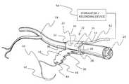
- FIG. 1is a schematic perspective view of one embodiment of the invention, showing the nerve cuff wrapped around a nerve and fastened with the adjustable closing mechanism.
- the figureshows a nerve interacting device in the form of conductive elements on the inner face of the nerve cuff and insulated leads to a stimulator or recording device.
- FIG. 2is a schematic plan view of the inner face of the nerve cuff of FIG. 1 , showing the cuff and conductive elements connected to the stimulator or recording device.
- FIG. 3is a schematic perspective view of the nerve cuff fitted around a nerve as in FIG. 1 , illustrating the removal of the excess tail end with surgical scissors once the cuff is properly positioned.
- FIG. 4is a schematic perspective view of a nerve cuff similar to that of FIG. 1 fitted around a large nerve.
- FIG. 5is a schematic perspective view of a nerve cuff similar to that of FIG. 1 fitted around a small nerve.
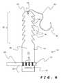
- FIG. 6is a schematic plan view of a nerve cuff similar to that of FIG. 1 , but with a nerve interacting device in the form of a multiple contact electrode lead.
- FIG. 7is a schematic plan view of the inner face of a nerve cuff illustrating a belt embodiment of the adjustable closing mechanism with multiple locking apertures on the tail end of the cuff and showing two multiple contact electrode leads as nerve interacting devices.
- FIG. 8is a schematic plan view of the inner face of a nerve cuff illustrating a further embodiment of a closing mechanism which resists movement equally in both directions once closed, and showing connection to a single multiple contact electrode lead as a nerve interacting device.
- FIG. 9is a side sectional and schematic view illustrating a method of locking the adjustable nerve cuff of FIG. 1 by wrapping it around the nerve and using a needle and suture to lock the cuff in place with a suture to the cuff itself.
- FIG. 10is a side sectional and schematic view illustrating the nerve cuff of FIG. 6 prior to cutting and discarding the excess tail end.
- FIG. 11is a side sectional and schematic view illustrating a method of anchoring the nerve cuff of FIG. 6 to nearby body tissue.
- FIG. 12is a schematic plan view of the inner face a nerve cuff with a closing mechanism similar to that of FIGS. 1 and 6 , but formed with custom printed connections as the nerve interacting device.
- FIG. 13is a schematic plan view of the outer face of a nerve cuff with printed connections and imbedded electronics and having a loop closing mechanism.
- FIG. 14is a side sectional and schematic view of the installed nerve cuff of FIG. 13 with printed connections and fully imbedded electronics, showing the loop closing mechanism in its locked position around the nerve.
- FIG. 15is a schematic plan view of the inner face of a nerve cuff with the closing mechanism similar to that of FIG. 13 , but showing a perpendicular electrode lead, and having printed conductive elements on the inner face of the nerve cuff.
- FIG. 16is a side sectional and schematic view of the nerve cuff of FIG. 15 in its locked position around the nerve.
- FIG. 17is a schematic perspective view of a nerve cuff fitted around a nerve and holding a BIONTM wireless stimulator device in proximity to the nerve.
- the BIONhas an antenna for wireless transmission to a stimulator control or recording device control unit.
- FIG. 18is a schematic plan view of the inner face of a nerve cuff showing conductive elements on the inner face of the nerve cuff and a wireless antenna device on the outer face of the nerve cuff for wireless transmission to a stimulator or recording device control unit.
- FIG. 19is a schematic plan view of the inner face of the nerve cuff apparatus used in the example of this application with an implanted conductor for nerve stimulation. Exemplary but non-limiting dimensions are provided on the figure.
- tissue cuff of the figuresis shown in the form of a nerve cuff, but the invention has broad application to other internal body tissues such as veins and arteries or other body tissues which can be encircled with a tissue cuff apparatus for purposes such as healing, attaching other devices or tissues, or immobilizing. While some dimensions are provided herein, the dimensions are non-limiting, and are provided as exemplary guidelines for preferred embodiments involving nerves, where typical nerve circumferences may be about 3 to 5 mm in diameter.
- the nerve cuff apparatus of this invention as illustrated in FIGS. 1-6is shown generally at 10 , and includes a nerve cuff 12 and a nerve interacting device 14 .
- the nerve cuff 12consists of a strap 16 formed of a thin, flat sheet of a non-conductive, biocompatible, elastomeric material that can be wrapped around a peripheral nerve 18 .
- the nerve 18is usually composed of multiple fascicles 20 , so adjustment of the nerve interacting device 14 , relative to the fascicles 20 may be desired during implantation (i.e., intra-operatively).
- the nerve interacting device 14includes conductive elements (in this case electrode units) 22 , 24 imbedded in the strap 16 (or printed or attached) direct contact to the nerve 18 .
- the non-conductive properties of the elastomeric materialensures that surrounding body tissue is insulated from the electrode units 22 , 24 .
- the strap 16is elongated with a longitudinal axis along its length dimension, and a transverse width dimension. The length dimension is longer than that needed to wrap around the body tissue of interest.
- the width dimensionis sufficient to provide structural support for the nerve interacting device of interest and sufficient to be manipulated during implantation. The width dimension (which may be constant over the length, or varied) of the strap 16 will depend on the thickness of the strap 16 , and the particular application for the nerve cuff apparatus 10 .
- the strap 16is thin.
- the strap thicknessis preferably less than about 1 mm, more preferably less than about 0.5 mm, and still more preferably between about 0.15-0.35 mm.
- the strap 16is sufficiently thin that it remains elastic, pliable and flexible for implanting, fastening, and adjusting.
- One set of exemplary, non-limiting dimensions for nerves of about 3 to 5 mm diameteris shown in FIG. 19 .
- the strap 16includes a body portion 26 connected between (preferably integral with) a head end portion 28 and a tail end portion 30 (best seen in FIG. 2 ).
- the body portion 26has an inner face 32 which faces the nerve to be encircled, and an outer face 34 which faces surrounding body tissues after implantation.
- the head and tail end portions 28 , 30are configured for adjustable length fastening one to the other around the nerve 18 , and thus provide the adjustable locking or closing mechanism of this invention. This leaves the body portion 26 isolated and remote from the adjustable length ends 28 , 30 , for stable and secure attachment to the nerve 18 , and for separate and secure attachment to one or more nerve interacting devices 14 .
- the adjustable length fasteningis generally achieved by providing the extra length (i.e., a total length of the strap 16 which is in excess of an expected circumference of a body tissue to be encircled) in one or both of the head and tail end portions 28 , 30 .
- the length of the body portion 26will not be greater than the expected circumference of the body tissue to be encircled, so the extra length is provided in one or both of the head and tail end portions 28 , 30 to ensure a secure attachment to the body tissue.
- the body tissueis very small, such as nerves
- providing extra length in both the head and tail end portions 28 , 30may be advantageous to assist in placement and manipulation during implantation.
- the head end portion 28is shown in the embodiment of FIGS. 1-6 to be formed with a transverse slot 36 as a locking aperture.
- the tail end portion 30is formed with a plurality of longitudinally spaced laterally paired locking projections 38 .
- the paired locking projections 38are spaced by narrower neck portions 39 .
- the locking projections 38are shaped to allow for passage through the slot 36 by flexing in an insertion direction (i.e., in the direction of threading through the slot 36 to fasten around the nerve 18 ), and to restrict movement in the reversing direction through the slot 36 (i.e., in the direction to loosen the strap 16 ).
- the flexibility of the projections 38permits them to be re-adjusted by the surgeon during implantation in the reverse direction if needed, but once the appropriate position is achieved, the projections 38 resist reverse movement through the slot 36 .
- the pairs of locking projections 38have a transverse width at their widest points which exceeds the transverse width dimension of the slot 36 .
- the narrow neck portions 39have a maximum transverse width dimension no greater than the transverse width dimension of the slot 36 . This enables the strap 16 to lay flat against the nerve 18 when fastened.
- the locking projections 38are preferably shaped to assist in threading through the slot 36 . For instance, with the arrow shape projections 38 of FIGS.
- the double toothed lateral edgesare tapered to narrow inwardly toward the leading edge 44 (free end) of the tail end portion 30 .
- Each pair of projections 38 at its widest pointhas a transverse width that extends transversely beyond the slot width in an overlapping and locking mode.
- the extent of overlap of each projection 38 (i.e., on each side of the slot 36 ) compared to the transverse slot widthis preferably at least about 10% of the slot width dimension, more preferably about 15-30%. This overlap of the projections resists reverse movement of the projections 38 through the slot 36 .
- the length of the individual projections 38 and the number of longitudinally spaced paired projections 38will vary to provide sufficient incremental adjustments around the nerve.
- the projection length and degree of overlapvary with such factors as the type and thickness of the elastomeric material, the nature (ex. size and weight) of the nerve interacting device 14 , and the nature and size of the body tissue being encircled, so the above dimensions are provided only as guidelines.
- the taper of the arrow shaped projections 38(narrowing toward the leading edge 44 of the tail end portion 30 ) provides a preferential sliding direction (in the insertion direction) when engaged in the slot 36 .
- the tail end portion 30may include a suture 40 and needle 42 at its leading edge 44 to assist in threading through the slot 36 , and for locking and/or anchoring to the strap 16 once implanted (see FIGS. 9-11 ).
- the leading edge 44might be formed with a suture connecting aperture 46 , or the needle 42 can be used to attach to the leading edge 44 before or during implantation.
- the strap 16is wrapped circumferentially around the nerve 18 in order to create a good contact between the nerve 18 and the conductive elements 22 , 24 .
- Insulated leads 48 , 50 and 52are shown leading to a remote stimulator or recording device 54 , which might be implanted or external to the patient.
- the conductive elements 22 , 24might be printed on, imbedded in or attached to (for example with adhesive) the inner face 32 of the body portion 26 , by techniques known in the art.
- the conductive elements 22 , 24might be conductive metal or conductive rubber. Alternatively, the conductive elements might be designed to receive other than electrical impulses, for example one or more of thermal, auditory, vibrational, light or fluid stimulation.
- FIGS. 3-5once properly positioned the excess at the tail end portion 30 can be trimmed using medical scissors 55 to remove excess material and reduce mechanical irritation.
- the excess trimmed tail end material 56(see FIGS. 4 , 5 ) containing the suture 40 and needle 42 can then be discarded.
- FIGS. 4 and 5show how the same sized nerve cuff 12 can wrap around two different sized nerves, a large nerve 18 in FIG. 4 and a smaller nerve 18 in FIG. 5 .
- the small nerve 18generates longer excess material 56 when compared to the excess material 56 from the large nerve 18 , if cut the same distance (marked with a dotted line) from the projection 38 engaged in the head end slot 36 .
- FIGS. 6-8show alternate embodiments of a nerve cuff apparatus of this invention with nerve interacting devices in the form of one or more multiple contact electrode leads 60 .
- Multiple contact electrode leads 60include a plurality of conductive elements 62 in order to achieve a specific stimulation or recording result. These leads 60 might be simply held in place by simple wrapping with the nerve cuff 12 , as in FIG. 6 , or they might be held with a non-conductive biocompatible adhesive 64 as shown in FIGS. 7 and 8 .
- FIG. 7illustrates an alternate closing/locking mechanism, namely a belt style closure.
- the strap 66is formed with a plurality of longitudinally spaced slots 68 formed in the tail end portion 70 .
- the head end portion 72is formed with laterally paired locking projections 74 .
- the leading edge 76 of the head end portion 72forms an elongated lead tab 78 to assist in threading into one of the slots 68 .
- the lead tab 78may also be attached to a suture 80 and needle 82 as above described.
- the preferred width dimensions of the projections 74 , narrower neck portion 84 and slots 68are generally as set forth above.
- the space 86 adjacent the narrower neck portion 84 between the head and body portions 72 , 88has a length component no less than the thickness dimension of the strap 66 . This assists in preventing the closure from re-opening.
- the nerve cuff strap 90is similar to that of FIG. 6 , but the tail end portion 92 is formed with laterally paired projections 94 which are rounded, rather than tapered. These rounded projections 94 resist movement in both directions equally once fitted through the locking slot 96 formed in the head end portion 98 .
- the strap 90is formed with an elongated lead tab 100 at the leading edge 102 of the tail end portion 92 to facilitate threading the tail end portion 92 into the locking slot 96 .
- FIGS. 9-11illustrate cross sectional views of different possible anchoring and locking methods for a nerve cuff 12 similar to that of FIGS. 1 or 6 .
- To lock the nerve cuff 12 in placeit is possible to wrap the excess at the tail end portion 30 around the cuff 12 , as seen in FIG. 9 .
- the needle 42 and suture 40can be used to tie the head end portion 28 with the tail end portion 30 via a stitch 104 . This reduces the chance of the nerve cuff 12 unraveling, and can be used to optimize contact between the conductive elements 22 , 24 and the nerve 18 .
- the cuff 12can also be left as is once the tail end portion 30 has been inserted into the head end portion 28 as shown in FIG.
- the suture 40 and needle 42can also be used to anchor the entire cuff 12 to nearby tissue 106 by stitching the tail end portion 30 via a stitch 108 to the nearby tissue 106 , as seen in FIG. 11 .
- the nerve interacting devicemay take the form of a circuit printed the body portion 110 of a nerve cuff strap 112 , between the head end and tail end portions 114 , 116 .
- the inner face 117 of the body portion 110is shown, but the circuit components might be printed on either or both sides, or the components may be imbedded in the strap 112 .
- the closing mechanismis similar to that shown in FIG. 6 .
- the processes of photolithography and electroplatingcan be used to generate custom conductive element contact points 118 , 119 , 120 , 121 that are unique in size and location to suit the nerve or tissue interacting device application. Some of these contact points 118 - 121 can be linked to each other with conductive but insulated tracks 122 .
- an electronic circuitis shown on the outer face 123 of a nerve cuff strap 124 .
- Printing techniques as above-mentionedcan be used to create electric circuits such as pre-amplifiers, or entire stimulator/recording devices that can be placed directly on the of the strap 124 .
- Exemplary electronic componentsare shown as a micro processor 125 , resistor 126 , and capacitor 127 , connected with can be connected with conductive and insulated tracks 128 . These are shown on the outer face 123 in FIGS. 13 , 14 , with the electrical contacts 131 being shown on the inner face 129 for contact with the nerve 18 .
- the entire electronic assembly on the outer face 123can be covered in an insulating biocompatible material 130 such as silicone rubber to prevent direct tissue interaction with the electronics.
- FIGS. 13 , 14also illustrate another embodiment for length adjustable closing mechanism.
- the strap 124 with head and tail end portions 132 , 134 , and body portion 133has a loop 136 (ex. ring) formed at the head end portion 132 .
- the loop 136sits above the plane of the strap 124 , and may be connected to the strap 124 , for example by a biocompatible adhesive.
- the opening 137 formed between the strap 124 and the loop 136functions as a locking aperture to secure the laterally paired locking projections 138 formed on the tail end portion 134 .
- the width of the pairs of projections 138 at their widest pointsis greater than the transverse width of the loop opening 137 .
- the loop 136rests on top of the head end portion 132 (best seen in FIG. 14 ).
- the loop 136might be provided as a separate ring which is attached by adhesive, similar to the figures.
- the loop 136 and strap 124can be made from a single thin insulating, flexible sheet of biocompatible material by folding side wings (not shown) inwardly to form the loop 136 , and fixing with adhesive.
- the shape of the pairs of projections 138 shown in FIG. 13is generally tear drop shaped with extra downward taper (toward the body portion 133 ), for ease of insertion in the loop 136 , and to increase the resistance to reverse movement through the loop 136 once fastened in the loop 136 .
- tear drop shaped projections 138may also be used in slot embodiments (see FIG. 19 ).
- the leading edge 140 of the tail end portion 134is formed with an elongated lead tab 142 having a transverse width at its leading edge 140 which is substantially smaller than the transverse width of the loop opening 137 . This facilitates insertion of the tail end portion 134 through the opening 137 .
- FIGS. 15 , 16A nerve cuff apparatus to accommodate this orientation is shown in FIGS. 15 , 16 .
- the nerve cuff strap 124is similar to that of FIGS. 13 , 14 , so FIGS. 15 , 16 show like components with the same reference numerals.
- FIG. 15shows the inner face 129 printed with conductive elements 144 , 145 for electrical contact with the nerve 18 .
- the insulated leads 146 from the elements 144 , 145are oriented to be perpendicular to the nerve 18 on implantation (rather than parallel as in previous embodiments). This is the ideal application for the loop closure mechanism.
- the loop 136is shown in the closed position to orient the opening 137 above the inner face 129 (the strap is shown with the outer face 123 in FIG. 14 , so the loop opening 137 there is above the outer face 123 ).
- FIGS. 17 and 18illustrate a complete wireless stimulator anchored in immediate proximity to the nerve 18 .
- a wireless stimulator 150such as a BIONTM from Advanced Bionics, LLC of California (see for example U.S. Pat. No. 5,193,539 to Schulman et al.) is attached with adhesive (not shown) to the inner face 165 of the body portion 154 of the nerve cuff strap.
- the BION 150is a self sufficient unit with an outer shell that is conductive for electrical contact with the nerve 18 .
- the BIONreceives data and/or power from an external control or recording unit 158 via an antenna 160 on the BION unit 150 .
- Radio waves 162may be used to control the unit 150 or transmit to the controller/recorder 158 .
- the nerve apparatus of the embodiment in FIG. 18has conductive elements (example metal contacts) 161 , 163 printed, attached or imbedded at the inner face 164 of the body portion 154 of strap 156 for direct contact with the nerve 18 once installed.
- the wireless control or recording unit 158can be located externally to the patient, or may be implanted.
- the laterally paired projections 166 on the tail end portion 168are shown as arrow shaped in FIG. 17 (as in FIG. 6 ) with needle 42 , suture 40 , and tear drop shaped in FIG. 18 (similar to FIG. 13 ).
- the leading edge 170 in FIG. 18is shown as forming an elongated tab 172 , connected to needle 42 and suture 40 , similar to that in earlier figures.
- the slotsmight be more oval shaped or circular shaped, with the projections being similarly altered so as to still project in a transverse width direction beyond the transverse width dimension at the widest point of the slot.
- the projectionsmight be shaped in 3D (and not just in 2D) to lock in the locking aperture to resist movement in the reversing direction.
- the above-described 2D embodimentsare preferred for their manufacturing simplicity and low cost, as well as for their ease of manipulation during implantation.
- Nerve stimulating devicesare well known in the prior art.
- Nerve recording devicesare also known.
- nerve recordings from sacral root recordings intra-operatively as electroneurographic (ENGs) signalsmay be obtained from either free electrodes or nerve cuffs. These are common in procedures for spinal cord injured patients that focus on the sacral roots of the spinal cord.
- Devices that have both stimulation and recording capabilitiesmight also be used, such as shown in U.S. Pat. No. 5,913,882 to King, designed for augmenting electrical stimulation usefulness in pain control.
- devices for sleep apnea via vagal nerve stimulation, or devices for Parkinson's disease in the form of deep brain stimulationmight be used with the nerve cuff of this invention.
- the substrate materials for the strapextend to elastomeric materials which provide sufficient elasticity, resiliency and strength in a thin flat format, without the corrugations, undulations or piercing projections of the prior art.
- the materialsare biocompatible for implantation, and are preferably non-conductive to protect/insulate surrounding body tissue from any conductive elements (typically electrical contacts).
- Exemplary materialsinclude flat sheets of silicone rubber elastomers, for example PDMS (polydimethylsiloxane), SilasticTM (a silicone rubber), and biocompatible polyurethane polymers, and biocompatible polyimides.
- the sheetshave a uniform thickness so that the strap is formed with a uniform thickness.
- the strapmight alternatively be formed with increased thickness in the certain body, head or tail portions to increase the strength of one or more of these sections for particular applications.
- Other elastomeric biocompatible materialswill be known to those skilled in the biomedical area.
- the substrate materialmay be coated or impregnated with one or more active tissue agents, such as antibiotics, proteins, growth factors and the like, for applications such as healing.
- the adhesivesare biocompatible, with exemplary materials including silicone rubber, cyanoacrylates, and polyethylene glycol polymers.
- exemplary materialsincluding silicone rubber, cyanoacrylates, and polyethylene glycol polymers.
- the latter groupare advantageous in applications where a biodegradable adhesive is desired.
- Manufacturinginvolves the shaping, cutting or stamping of a sheet of non-conductive biocompatible elastomeric material. Laser cutting is preferred, particularly for the fine details and dimensions of the projections and slots.
- the conductive elements(for example conductive metals or conductive rubber) may be imbedded, attached or printed into or on the sheet. The entire cuff apparatus can then be sterilized prior to implantation.
- the nerve cuff apparatus of this inventionin multiple of the preferred embodiments has been tested in numerous animal trials where the application was an electrical nerve cuff.
- a plurality of nerve cuff apparatus 180having the configuration and dimensions shown in FIG. 19 (not drawn to scale) were implanted in a 51 year old spinal cord injured man.
- the implantationwas directed to restore upper extremity hand function in conjunction with a nerve stimulator device as described in U.S. Patent Application No. 2006/0184211 A, published Aug. 17, 2006, to Gaunt et al.
- the nerve cuff straps 182were each laser cut out of a biocompatible silicone rubber sheet 0.254 mm thick.
- the implanted nerve cuff apparatus 180included a monopolar conductor 184 attached to the body portion 186 of the nerve cuff strap 182 with a silicone rubber adhesive 188 , cured prior to sterilization and implantation.
- the tail end portion 190was formed with tear drop shaped projections 194 as shown, and an elongated lead tab 196 to aid in manipulating into the slot 198 formed in the head end portion 200 .
- the head end portion 200 of the nerve cuff strap 182was lengthened with excess length material in order to aid in manipulation of the cuff apparatus 180 during implantation.
- the nerve cuff apparatus 180once circumferentially attached to the target nerves was tested with stimulation to verify proper positioning.
- Positionwas adjusted on each of the three implanted cuffs during the implantation procedure (i.e., intra-operatively), until the most favorable results were observed.
- Each cuff apparatus 180was then trimmed (both the head and tail end portions 200 , 190 ) with surgical scissors (as shown in FIG. 3 ). Five months later, all three implantation sites continued to stimulate the desired nerves, with no sign of apparatus migration or failure.
- the word “comprising”is used in its non-limiting sense to mean that items following the word in the sentence are included and that items not specifically mentioned are not excluded.
- the use of the indefinite article “a” in the claims before an elementmeans that one of the elements is specified, but does not specifically exclude others of the elements being present, unless the context clearly requires that there be one and only one of the elements.
- a slotas used herein and in the claims may include multiple slots.
Landscapes
- Health & Medical Sciences (AREA)
- Life Sciences & Earth Sciences (AREA)
- Heart & Thoracic Surgery (AREA)
- Neurology (AREA)
- Veterinary Medicine (AREA)
- Public Health (AREA)
- General Health & Medical Sciences (AREA)
- Animal Behavior & Ethology (AREA)
- Engineering & Computer Science (AREA)
- Biomedical Technology (AREA)
- Surgery (AREA)
- Medical Informatics (AREA)
- Molecular Biology (AREA)
- Pathology (AREA)
- Biophysics (AREA)
- Neurosurgery (AREA)
- Physics & Mathematics (AREA)
- Physiology (AREA)
- Orthopedic Medicine & Surgery (AREA)
- Cardiology (AREA)
- Nuclear Medicine, Radiotherapy & Molecular Imaging (AREA)
- Radiology & Medical Imaging (AREA)
- Electrotherapy Devices (AREA)
Abstract
Description
- i. providing a tissue cuff as described above;
- ii. wrapping the strap around the body tissue; and
- iii. fastening the tail end portion and the head end portion together with an appropriate one of the laterally paired locking projection and locking apertures, whereby the plurality of locking apertures or the plurality of laterally paired projections allows for a circumference of the tissue cuff to be adjusted intra-operatively for a particular circumference of the body tissue.
- 1. One size fits various nerve sizes or configurations. The exact nerve sizes are typically not known in advance of implantation, so the length adjustability for intra-operative manipulation provides a more secure and stable attachment to the nerve, limiting additional surgical procedures needed in the event of device migration.
- 2. Once fastened, the excess material in the tail end portion of the nerve cuff can be trimmed or sutured shut. The excess tail end material might alternatively serve as anchoring material by suturing to surrounding body tissue.
- 3. The adjustable fastening mechanism allows for intra-operative adjustment for different nerve sizes and re-positioning around the nerve until the desired result is obtained, minimizing post operative failures or migration of the apparatus.
- 4. The initial flat configuration makes the cuff easy to sterilize, manufacture and insert around the nerve.
- 5. The body portion being clear of the fastening head and tail end portions, allows for use with a wide range of conductive elements and nerve interacting devices. For instance, metal conductive elements and circuits can be printed on the inner face of the flat body portion in unique arrangements. In addition, or alternatively, other circuit components may be imbedded into the body portion or otherwise attached (similar to electronic boards). The outer face of body portion may also carry circuit components, or serve to attach nerve interacting devices. Alternatively, Silastic materials can accommodate conductive and non-conductive rubber instead of printed metal. Alternatively, the body portion can accommodate multiple conductive contacts, and can be used to secure a traditional barb/tube electrode close to the nerve. Still alternatively, a BION may be secured close to the nerve with the nerve cuff to prevent shifting.
- 6. The needle and suture at the tail end allows for intuitive and minimally destructive approach to installing the cuff (as a guide). The needle may be metal, and the suture a traditional suture. Alternatively, the needle might be plastic, and the suture a thin sheet of rubber.
Claims (21)
Priority Applications (1)
| Application Number | Priority Date | Filing Date | Title |
|---|---|---|---|
| US12/370,364US8116882B2 (en) | 2008-02-15 | 2009-02-12 | Adjustable tissue or nerve cuff and method of use |
Applications Claiming Priority (2)
| Application Number | Priority Date | Filing Date | Title |
|---|---|---|---|
| US2926908P | 2008-02-15 | 2008-02-15 | |
| US12/370,364US8116882B2 (en) | 2008-02-15 | 2009-02-12 | Adjustable tissue or nerve cuff and method of use |
Publications (2)
| Publication Number | Publication Date |
|---|---|
| US20090210042A1 US20090210042A1 (en) | 2009-08-20 |
| US8116882B2true US8116882B2 (en) | 2012-02-14 |
Family
ID=40955826
Family Applications (1)
| Application Number | Title | Priority Date | Filing Date |
|---|---|---|---|
| US12/370,364Expired - Fee RelatedUS8116882B2 (en) | 2008-02-15 | 2009-02-12 | Adjustable tissue or nerve cuff and method of use |
Country Status (3)
| Country | Link |
|---|---|
| US (1) | US8116882B2 (en) |
| CA (1) | CA2715543C (en) |
| WO (1) | WO2009100531A1 (en) |
Cited By (22)
| Publication number | Priority date | Publication date | Assignee | Title |
|---|---|---|---|---|
| US20120277819A1 (en)* | 2011-04-29 | 2012-11-01 | Cyberonics Inc. | Overwrap for nerve stimulation system |
| DE202013002803U1 (en) | 2013-03-22 | 2013-04-09 | Inomed Medizintechnik Gmbh | Electrode arrangement for electrical stimulation of nerves |
| WO2016039768A1 (en)* | 2014-09-12 | 2016-03-17 | Neuros Medical, Inc | Nerve cuff electrode for neuromodulation in large human nerve trunks |
| CN106659405A (en)* | 2014-07-10 | 2017-05-10 | 欧姆龙健康医疗事业株式会社 | Blood pressure measurement cuff and method for attaching same |
| US10231736B2 (en) | 2015-06-11 | 2019-03-19 | The Regents Of The University Of California | System and method for soft tissue gripping |
| US10589089B2 (en) | 2017-10-25 | 2020-03-17 | Epineuron Technologies Inc. | Systems and methods for delivering neuroregenerative therapy |
| US10758723B2 (en) | 2011-05-19 | 2020-09-01 | Neuros Medical, Inc. | Nerve cuff electrode for neuromodulation in large human nerve trunks |
| US20200276379A1 (en)* | 2019-02-28 | 2020-09-03 | Biosurfaces, Inc. | Tissue cuff |
| US10981000B2 (en) | 2017-05-02 | 2021-04-20 | The Alfred E. Mann Foundation For Scientific Research | Self-expanding nerve cuff electrode |
| US11116965B2 (en) | 2017-12-13 | 2021-09-14 | Neuros Medical, Inc. | Nerve cuff deployment devices |
| US11213682B2 (en) | 2018-04-09 | 2022-01-04 | Neuros Medical, Inc. | Apparatuses and methods for setting an electrical dose |
| US11247045B2 (en) | 2017-10-25 | 2022-02-15 | Epineuron Technologies Inc. | Systems and methods for delivering neuroregenerative therapy |
| US11247043B2 (en) | 2019-10-01 | 2022-02-15 | Epineuron Technologies Inc. | Electrode interface devices for delivery of neuroregenerative therapy |
| EP3970788A1 (en)* | 2018-03-02 | 2022-03-23 | Aleva Neurotherapeutics SA | Neurostimulation device |
| US11311718B2 (en) | 2014-05-16 | 2022-04-26 | Aleva Neurotherapeutics Sa | Device for interacting with neurological tissue and methods of making and using the same |
| US11413458B2 (en) | 2011-05-19 | 2022-08-16 | Neuros Medical, Inc. | Nerve cuff electrode for neuromodulation in large human nerve trunks |
| US11766560B2 (en) | 2010-04-01 | 2023-09-26 | Ecole Polytechnique Federale De Lausanne | Device for interacting with neurological tissue and methods of making and using the same |
| US11833348B2 (en) | 2021-07-09 | 2023-12-05 | The Alfred E. Mann Foundation For Scientific Research | Electrode leads having multi-application helical nerve cuffs and associated systems and methods |
| US11878172B2 (en) | 2020-02-11 | 2024-01-23 | Neuros Medical, Inc. | System and method for quantifying qualitative patient-reported data sets |
| US12194290B2 (en) | 2020-09-02 | 2025-01-14 | The Alfred E. Mann Foundation For Scientific Research | Electrode leads having multi-application nerve cuffs and associated systems and methods |
| US12296172B2 (en) | 2022-02-01 | 2025-05-13 | The Alfred E. Mann Foundation For Scientific Research | Electrode leads having nerve contact elements with coil contacts and associated systems and methods |
| US12350489B2 (en) | 2021-03-30 | 2025-07-08 | The Alfred E. Mann Foundation For Scientific Research | Electrode leads having nerve cuffs and associated systems and methods |
Families Citing this family (56)
| Publication number | Priority date | Publication date | Assignee | Title |
|---|---|---|---|---|
| US11207518B2 (en) | 2004-12-27 | 2021-12-28 | The Feinstein Institutes For Medical Research | Treating inflammatory disorders by stimulation of the cholinergic anti-inflammatory pathway |
| WO2007098200A2 (en) | 2006-02-16 | 2007-08-30 | Imthera Medical, Inc. | An rfid-based apparatus, system, and method for therapeutic treatment of obstructive sleep apnea |
| EP2197536A1 (en) | 2007-10-09 | 2010-06-23 | Imthera Medical, Inc. | System and method for neural stimulation |
| CN102112177A (en)* | 2008-05-02 | 2011-06-29 | 梅德特龙尼克有限公司 | Self expanding electrode cuff |
| EP2349139B1 (en) | 2008-10-09 | 2017-05-31 | Imthera Medical, Inc. | Stimulation of a hypoglossal nerve for controlling the position of a patient's tongue |
| US8515520B2 (en)* | 2008-12-08 | 2013-08-20 | Medtronic Xomed, Inc. | Nerve electrode |
| US9211410B2 (en) | 2009-05-01 | 2015-12-15 | Setpoint Medical Corporation | Extremely low duty-cycle activation of the cholinergic anti-inflammatory pathway to treat chronic inflammation |
| US20100298916A1 (en)* | 2009-05-22 | 2010-11-25 | Pierre Rabischong | Pelvic implanted neural electrode and method for implanting same |
| AU2010254490B2 (en)* | 2009-05-26 | 2014-06-12 | Cardiac Pacemakers, Inc. | Helically formed coil for a neural cuff electrode |
| WO2010144578A2 (en)* | 2009-06-09 | 2010-12-16 | Setpoint Medical Corporation | Nerve cuff with pocket for leadless stimulator |
| JP2011055912A (en)* | 2009-09-07 | 2011-03-24 | Terumo Corp | Electric stimulator |
| WO2011059531A1 (en) | 2009-11-10 | 2011-05-19 | Imthera Medical, Inc. | System for stimulating a hypoglossal nerve for controlling the position of a patient's tongue |
| WO2014169145A1 (en) | 2013-04-10 | 2014-10-16 | Setpoint Medical Corporation | Closed-loop vagus nerve stimulation |
| WO2011074339A1 (en)* | 2009-12-14 | 2011-06-23 | テルモ株式会社 | Electric stimulation device |
| EP2515996B1 (en) | 2009-12-23 | 2019-09-18 | Setpoint Medical Corporation | Neural stimulation devices and systems for treatment of chronic inflammation |
| JP5577469B2 (en) | 2010-09-15 | 2014-08-20 | カーディアック ペースメイカーズ, インコーポレイテッド | Automatic selection of lead configuration for neural stimulation leads |
| US12172017B2 (en) | 2011-05-09 | 2024-12-24 | Setpoint Medical Corporation | Vagus nerve stimulation to treat neurodegenerative disorders |
| WO2013003278A1 (en) | 2011-06-28 | 2013-01-03 | Cardiac Pacemakers, Inc. | Strain relief feature for an implantable medical device lead |
| US8639355B2 (en) | 2011-07-07 | 2014-01-28 | Cardiac Pacemakers, Inc. | Insulation and stability features for an implantable medical device lead |
| US8934992B2 (en) | 2011-09-01 | 2015-01-13 | Inspire Medical Systems, Inc. | Nerve cuff |
| EP2827944B1 (en) | 2012-03-21 | 2016-05-18 | Cardiac Pacemakers, Inc. | Systems and methods for stimulation of vagus nerve |
| WO2014055393A1 (en) | 2012-10-02 | 2014-04-10 | Cardiac Pacemakers, Inc. | Pinch to open cuff electrode |
| US9114250B2 (en) | 2012-10-02 | 2015-08-25 | Cardiac Pacemakers, Inc. | Pinch to open cuff electrode |
| WO2014106023A1 (en) | 2012-12-28 | 2014-07-03 | Cardiac Pacemakers, Inc. | Stimulation cuff and implantation tool |
| EP2956208B1 (en) | 2013-02-13 | 2021-01-13 | Cardiac Pacemakers, Inc. | Cuff electrode with integrated tendril |
| US10166386B2 (en)* | 2013-10-14 | 2019-01-01 | The Board Of Regents Of The University Of Oklahoma | Implantable electrode assembly |
| US20160263376A1 (en) | 2013-11-27 | 2016-09-15 | The Governing Council Of The University Of Toronto | Systems and methods for improved treatment of overactive bladder |
| US10556107B2 (en) | 2013-11-27 | 2020-02-11 | Ebt Medical, Inc. | Systems, methods and kits for peripheral nerve stimulation |
| US11633593B2 (en) | 2013-11-27 | 2023-04-25 | Ebt Medical, Inc. | Treatment of pelvic floor disorders using targeted lower limb nerve stimulation |
| US9610442B2 (en) | 2015-05-21 | 2017-04-04 | The Governing Council Of The University Of Toronto | Systems and methods for treatment of urinary dysfunction |
| CA3190484A1 (en)* | 2013-11-27 | 2015-06-04 | Ebt Medical, Inc. | Systems and methods of enhancing electrical activation of nervous tissue |
| EP3107472A4 (en)* | 2014-02-21 | 2017-11-01 | Circuit Therapeutics, Inc. | System and method for therapeutic management of unproductive cough |
| EP2959938B1 (en)* | 2014-06-25 | 2017-03-22 | Sorin CRM SAS | Implantable probe comprising a sleeve which can be wound around an organ such as a nerve |
| US11311725B2 (en) | 2014-10-24 | 2022-04-26 | Setpoint Medical Corporation | Systems and methods for stimulating and/or monitoring loci in the brain to treat inflammation and to enhance vagus nerve stimulation |
| US10864369B2 (en)* | 2015-10-19 | 2020-12-15 | Sorin Crm Sas | Implantable probe comprising a perforated sleeve |
| US10596367B2 (en) | 2016-01-13 | 2020-03-24 | Setpoint Medical Corporation | Systems and methods for establishing a nerve block |
| US11471681B2 (en) | 2016-01-20 | 2022-10-18 | Setpoint Medical Corporation | Batteryless implantable microstimulators |
| CN108882885A (en) | 2016-01-20 | 2018-11-23 | 赛博恩特医疗器械公司 | Control of vagus nerve stimulation |
| US10583304B2 (en) | 2016-01-25 | 2020-03-10 | Setpoint Medical Corporation | Implantable neurostimulator having power control and thermal regulation and methods of use |
| US10814127B2 (en)* | 2016-02-05 | 2020-10-27 | Boston Scientific Neuromodulation Corporation | Slotted sleeve neurostimulation device |
| CN109069825A (en)* | 2016-03-14 | 2018-12-21 | 通用电气公司 | The assemble in situ of two-way neural interface |
| WO2018102773A1 (en) | 2016-12-02 | 2018-06-07 | Boston Scientific Neuromodulation Corporation | Methods and systems for selecting stimulation parameters for electrical stimulation devices |
| EP3664889B1 (en) | 2017-08-11 | 2024-02-21 | Inspire Medical Systems, Inc. | Cuff electrode |
| US11173307B2 (en) | 2017-08-14 | 2021-11-16 | Setpoint Medical Corporation | Vagus nerve stimulation pre-screening test |
| US11697026B2 (en) | 2017-12-15 | 2023-07-11 | Galvani Bioelectronics Limited | Systems and methods configured to deploy cuffs onto biological structures |
| US11890474B2 (en) | 2018-04-19 | 2024-02-06 | Iota Biosciences, Inc. | Implants using ultrasonic communication for modulating splenic nerve activity |
| CN112272575B (en) | 2018-04-19 | 2024-05-17 | 艾奧塔生物科技公司 | Implants using ultrasound communication for neural sensing and stimulation |
| IL311077B2 (en) | 2018-08-29 | 2025-07-01 | Iota Biosciences Inc | Implantable closed-loop neuromodulation device, systems and methods for use |
| US11260229B2 (en) | 2018-09-25 | 2022-03-01 | The Feinstein Institutes For Medical Research | Methods and apparatuses for reducing bleeding via coordinated trigeminal and vagal nerve stimulation |
| WO2020210786A1 (en) | 2019-04-12 | 2020-10-15 | Setpoint Medical Corporation | Vagus nerve stimulation to treat neurodegenerative disorders |
| AU2020367447A1 (en) | 2019-10-17 | 2022-04-21 | Iota Biosciences, Inc. | Devices and methods for modulating immune system activity in a cancer patient and treating cancer |
| AU2020366508A1 (en)* | 2019-10-17 | 2022-04-21 | Iota Biosciences, Inc. | Helical nerve cuff and related implantable devices |
| EP4566539A1 (en) | 2020-05-21 | 2025-06-11 | The Feinstein Institutes for Medical Research | Systems and methods for vagus nerve stimulation |
| FR3114491B1 (en)* | 2020-09-29 | 2024-01-19 | Atrotech | ATRAUMATIC TAB FOR FIXING A NEUROSTIMULATION ELECTRODE ON A NERVE |
| AU2022277556B2 (en) | 2021-05-21 | 2025-03-06 | Boston Scientific Neuromodulation Corporation | Electrical stimulation cuff devices and systems with helical arrangement of electrodes |
| IT202200014269A1 (en)* | 2022-07-06 | 2024-01-06 | Scuola Superiore Di Studi Univ E Di Perfezionamento Santanna | NEURAL ELECTRODE MADE WITH SOFT POLYMERS AND RAPID PROTOTYPING TECHNIQUES |
Citations (20)
| Publication number | Priority date | Publication date | Assignee | Title |
|---|---|---|---|---|
| US3654933A (en) | 1968-11-18 | 1972-04-11 | Medtronic Inc | Implatable electrode |
| US3738368A (en) | 1970-12-14 | 1973-06-12 | R Avery | Implantable electrodes for the stimulation of the sciatic nerve |
| US3874034A (en)* | 1972-01-10 | 1975-04-01 | Mobil Oil Corp | Perforated thermoplastic plastic strap closure affixed to an open mouth bag structure |
| US4535764A (en)* | 1983-04-15 | 1985-08-20 | Tayco Developments, Inc. | Surgical bone tie |
| US4602624A (en) | 1984-10-11 | 1986-07-29 | Case Western Reserve University | Implantable cuff, method of manufacture, and method of installation |
| US5038781A (en) | 1988-01-21 | 1991-08-13 | Hassan Hamedi | Multi-electrode neurological stimulation apparatus |
| WO1993020887A1 (en) | 1992-04-20 | 1993-10-28 | Case Western Reserve University | Thin film implantable electrode and method of manufacture |
| US5487756A (en) | 1994-12-23 | 1996-01-30 | Simon Fraser University | Implantable cuff having improved closure |
| US5505201A (en) | 1994-04-20 | 1996-04-09 | Case Western Reserve University | Implantable helical spiral cuff electrode |
| US5634462A (en) | 1993-10-15 | 1997-06-03 | Case Western Reserve University | Corrugated inter-fascicular nerve cuff method and apparatus |
| US5913882A (en) | 1996-04-04 | 1999-06-22 | Medtronic Inc. | Neural stimulation techniques with feedback |
| WO2001022877A1 (en) | 1999-09-28 | 2001-04-05 | Neurocontrol | Flat interface nerve electrode and a method for use |
| US6600956B2 (en) | 2001-08-21 | 2003-07-29 | Cyberonics, Inc. | Circumneural electrode assembly |
| US20050148814A1 (en)* | 2004-01-05 | 2005-07-07 | Fischi Michael C. | Muscle function augmentation |
| WO2006017634A2 (en) | 2004-08-04 | 2006-02-16 | Ndi Medical, Llc | Devices, systems, and methods employing a molded nerve cuff electrode |
| US7072720B2 (en) | 1999-06-25 | 2006-07-04 | Emory University | Devices and methods for vagus nerve stimulation |
| US20060184211A1 (en) | 2004-01-22 | 2006-08-17 | Gaunt Robert A | Method of routing electrical current to bodily tissues via implanted passive conductors |
| WO2007082382A1 (en) | 2006-01-23 | 2007-07-26 | Rehabtronics Inc. | Method of routing electrical current to bodily tissues via implanted passive conductors |
| US7266885B1 (en) | 2000-03-02 | 2007-09-11 | Advanced Neuromodulation Systems, Inc. | Method of making a nerve cuff |
| WO2007140597A1 (en) | 2006-06-02 | 2007-12-13 | Victhom Human Bionics Inc. | Nerve cuff, method and apparatus for manufacturing same |
Family Cites Families (2)
| Publication number | Priority date | Publication date | Assignee | Title |
|---|---|---|---|---|
| US3378368A (en)* | 1965-01-04 | 1968-04-16 | Imp Metal Ind Kynoch Ltd | Titanium-base alloys |
| US20060184244A1 (en)* | 2005-02-14 | 2006-08-17 | Nguyen Tuan A | Biasing system for intraocular lens |
- 2009
- 2009-02-12WOPCT/CA2009/000171patent/WO2009100531A1/enactiveApplication Filing
- 2009-02-12USUS12/370,364patent/US8116882B2/ennot_activeExpired - Fee Related
- 2009-02-12CACA2715543Apatent/CA2715543C/ennot_activeExpired - Fee Related
Patent Citations (21)
| Publication number | Priority date | Publication date | Assignee | Title |
|---|---|---|---|---|
| US3654933A (en) | 1968-11-18 | 1972-04-11 | Medtronic Inc | Implatable electrode |
| US3738368A (en) | 1970-12-14 | 1973-06-12 | R Avery | Implantable electrodes for the stimulation of the sciatic nerve |
| US3874034A (en)* | 1972-01-10 | 1975-04-01 | Mobil Oil Corp | Perforated thermoplastic plastic strap closure affixed to an open mouth bag structure |
| US4535764A (en)* | 1983-04-15 | 1985-08-20 | Tayco Developments, Inc. | Surgical bone tie |
| US4602624A (en) | 1984-10-11 | 1986-07-29 | Case Western Reserve University | Implantable cuff, method of manufacture, and method of installation |
| US5038781A (en) | 1988-01-21 | 1991-08-13 | Hassan Hamedi | Multi-electrode neurological stimulation apparatus |
| WO1993020887A1 (en) | 1992-04-20 | 1993-10-28 | Case Western Reserve University | Thin film implantable electrode and method of manufacture |
| US5634462A (en) | 1993-10-15 | 1997-06-03 | Case Western Reserve University | Corrugated inter-fascicular nerve cuff method and apparatus |
| US5964702A (en) | 1994-04-20 | 1999-10-12 | Case Western Reserve University | Implantable helical spiral cuff electrode method of installation |
| US5505201A (en) | 1994-04-20 | 1996-04-09 | Case Western Reserve University | Implantable helical spiral cuff electrode |
| US5487756A (en) | 1994-12-23 | 1996-01-30 | Simon Fraser University | Implantable cuff having improved closure |
| US5913882A (en) | 1996-04-04 | 1999-06-22 | Medtronic Inc. | Neural stimulation techniques with feedback |
| US7072720B2 (en) | 1999-06-25 | 2006-07-04 | Emory University | Devices and methods for vagus nerve stimulation |
| WO2001022877A1 (en) | 1999-09-28 | 2001-04-05 | Neurocontrol | Flat interface nerve electrode and a method for use |
| US7266885B1 (en) | 2000-03-02 | 2007-09-11 | Advanced Neuromodulation Systems, Inc. | Method of making a nerve cuff |
| US6600956B2 (en) | 2001-08-21 | 2003-07-29 | Cyberonics, Inc. | Circumneural electrode assembly |
| US20050148814A1 (en)* | 2004-01-05 | 2005-07-07 | Fischi Michael C. | Muscle function augmentation |
| US20060184211A1 (en) | 2004-01-22 | 2006-08-17 | Gaunt Robert A | Method of routing electrical current to bodily tissues via implanted passive conductors |
| WO2006017634A2 (en) | 2004-08-04 | 2006-02-16 | Ndi Medical, Llc | Devices, systems, and methods employing a molded nerve cuff electrode |
| WO2007082382A1 (en) | 2006-01-23 | 2007-07-26 | Rehabtronics Inc. | Method of routing electrical current to bodily tissues via implanted passive conductors |
| WO2007140597A1 (en) | 2006-06-02 | 2007-12-13 | Victhom Human Bionics Inc. | Nerve cuff, method and apparatus for manufacturing same |
Non-Patent Citations (2)
| Title |
|---|
| Andreasen, LNS et al. (1998) "On the importance of configuration and closure of nerve cuff electrodes for recording"; Proceedings 20th Ann.Int.Conf. IEEE 20(6):3004-3007. |
| Int. Search Report and Written Opinion PCT/CA2009/000171. |
Cited By (35)
| Publication number | Priority date | Publication date | Assignee | Title |
|---|---|---|---|---|
| US11766560B2 (en) | 2010-04-01 | 2023-09-26 | Ecole Polytechnique Federale De Lausanne | Device for interacting with neurological tissue and methods of making and using the same |
| US20120277819A1 (en)* | 2011-04-29 | 2012-11-01 | Cyberonics Inc. | Overwrap for nerve stimulation system |
| US8965499B2 (en)* | 2011-04-29 | 2015-02-24 | Cyberonics, Inc. | Overwrap for nerve stimulation system |
| US11413458B2 (en) | 2011-05-19 | 2022-08-16 | Neuros Medical, Inc. | Nerve cuff electrode for neuromodulation in large human nerve trunks |
| US10758723B2 (en) | 2011-05-19 | 2020-09-01 | Neuros Medical, Inc. | Nerve cuff electrode for neuromodulation in large human nerve trunks |
| US12011597B2 (en) | 2011-05-19 | 2024-06-18 | Neuros Medical, Inc. | Nerve cuff electrode for neuromodulation in large human nerve trunks |
| DE202013002803U1 (en) | 2013-03-22 | 2013-04-09 | Inomed Medizintechnik Gmbh | Electrode arrangement for electrical stimulation of nerves |
| US11311718B2 (en) | 2014-05-16 | 2022-04-26 | Aleva Neurotherapeutics Sa | Device for interacting with neurological tissue and methods of making and using the same |
| CN106659405B (en)* | 2014-07-10 | 2020-05-22 | 欧姆龙健康医疗事业株式会社 | Cuff for blood pressure measurement and method of attaching the same |
| CN106659405A (en)* | 2014-07-10 | 2017-05-10 | 欧姆龙健康医疗事业株式会社 | Blood pressure measurement cuff and method for attaching same |
| CN107073263A (en)* | 2014-09-12 | 2017-08-18 | 纽若斯医疗公司 | Neural envelope electrodes for neuromodulation in large human neural trunks |
| CN107073263B (en)* | 2014-09-12 | 2021-07-23 | 纽若斯医疗公司 | Neural envelope electrodes for neuromodulation in large human neural trunks |
| WO2016039768A1 (en)* | 2014-09-12 | 2016-03-17 | Neuros Medical, Inc | Nerve cuff electrode for neuromodulation in large human nerve trunks |
| US10231736B2 (en) | 2015-06-11 | 2019-03-19 | The Regents Of The University Of California | System and method for soft tissue gripping |
| US10981000B2 (en) | 2017-05-02 | 2021-04-20 | The Alfred E. Mann Foundation For Scientific Research | Self-expanding nerve cuff electrode |
| US20210268270A1 (en)* | 2017-05-02 | 2021-09-02 | The Alfred E. Mann Foundation For Scientific Research | Nerve cuff electrode locking mechanism |
| US11247044B2 (en) | 2017-10-25 | 2022-02-15 | Epineuron Technologies Inc. | Devices for delivering neuroregenerative therapy |
| US11247045B2 (en) | 2017-10-25 | 2022-02-15 | Epineuron Technologies Inc. | Systems and methods for delivering neuroregenerative therapy |
| US12318608B2 (en) | 2017-10-25 | 2025-06-03 | Epineuron Technologies Inc. | Devices and methods for delivering neuroregenerative therapy |
| US10589089B2 (en) | 2017-10-25 | 2020-03-17 | Epineuron Technologies Inc. | Systems and methods for delivering neuroregenerative therapy |
| US11752331B2 (en) | 2017-12-13 | 2023-09-12 | Neuros Medical, Inc. | Nerve cuff deployment devices |
| US11116965B2 (en) | 2017-12-13 | 2021-09-14 | Neuros Medical, Inc. | Nerve cuff deployment devices |
| US11738192B2 (en) | 2018-03-02 | 2023-08-29 | Aleva Neurotherapeutics | Neurostimulation device |
| EP3970788A1 (en)* | 2018-03-02 | 2022-03-23 | Aleva Neurotherapeutics SA | Neurostimulation device |
| US12201837B2 (en) | 2018-04-09 | 2025-01-21 | Neuros Medical, Inc. | Apparatuses and methods for setting an electrical dose |
| US11730963B2 (en) | 2018-04-09 | 2023-08-22 | Neuros Medical, Inc. | Apparatuses and methods for setting an electrical dose |
| US11213682B2 (en) | 2018-04-09 | 2022-01-04 | Neuros Medical, Inc. | Apparatuses and methods for setting an electrical dose |
| US20200276379A1 (en)* | 2019-02-28 | 2020-09-03 | Biosurfaces, Inc. | Tissue cuff |
| US11247043B2 (en) | 2019-10-01 | 2022-02-15 | Epineuron Technologies Inc. | Electrode interface devices for delivery of neuroregenerative therapy |
| US11364381B2 (en) | 2019-10-01 | 2022-06-21 | Epineuron Technologies Inc. | Methods for delivering neuroregenerative therapy and reducing post-operative and chronic pain |
| US11878172B2 (en) | 2020-02-11 | 2024-01-23 | Neuros Medical, Inc. | System and method for quantifying qualitative patient-reported data sets |
| US12194290B2 (en) | 2020-09-02 | 2025-01-14 | The Alfred E. Mann Foundation For Scientific Research | Electrode leads having multi-application nerve cuffs and associated systems and methods |
| US12350489B2 (en) | 2021-03-30 | 2025-07-08 | The Alfred E. Mann Foundation For Scientific Research | Electrode leads having nerve cuffs and associated systems and methods |
| US11833348B2 (en) | 2021-07-09 | 2023-12-05 | The Alfred E. Mann Foundation For Scientific Research | Electrode leads having multi-application helical nerve cuffs and associated systems and methods |
| US12296172B2 (en) | 2022-02-01 | 2025-05-13 | The Alfred E. Mann Foundation For Scientific Research | Electrode leads having nerve contact elements with coil contacts and associated systems and methods |
Also Published As
| Publication number | Publication date |
|---|---|
| WO2009100531A1 (en) | 2009-08-20 |
| CA2715543C (en) | 2017-02-14 |
| CA2715543A1 (en) | 2009-08-20 |
| US20090210042A1 (en) | 2009-08-20 |
Similar Documents
| Publication | Publication Date | Title |
|---|---|---|
| US8116882B2 (en) | Adjustable tissue or nerve cuff and method of use | |
| US9364660B2 (en) | Electrode array device configured for placement inside the dura for direct spinal cord stimulation | |
| AU2019202771B2 (en) | Implant unit delivery tool | |
| US11730469B2 (en) | Implant unit delivery tool | |
| JP4635045B2 (en) | Modular stimulation lead network | |
| US9950165B2 (en) | Method for causing stochastic depolarization in the spinal cord to inhibit transmission of synchronous action potentials | |
| IL274618A (en) | Selective power supply conference tool for implant unit | |
| US20130267837A1 (en) | Electrical lead positioning systems and methods | |
| US20240325757A1 (en) | Devices and methods for improving headache disorders | |
| US20130123866A1 (en) | Neurostimulation system with lead fastener and methods of making and using | |
| JP5797062B2 (en) | Electrode placement system | |
| WO2019070211A2 (en) | An electrode embodiment for vagus nerve stimulator | |
| HK1203869B (en) | Managing back pain by applying a high frequency electrical stimulus directly to the spinal cord |
Legal Events
| Date | Code | Title | Description |
|---|---|---|---|
| AS | Assignment | Owner name:ANGELTEAR SOLUTIONS INC., CANADA Free format text:ASSIGNMENT OF ASSIGNORS INTEREST;ASSIGNOR:KOWALCZEWSKI, JON;REEL/FRAME:022258/0759 Effective date:20090211 | |
| AS | Assignment | Owner name:ANGELTEAR SOLUTIONS INC., CANADA Free format text:CORRECTIVE ASSIGNMENT TO CORRECT THE SPELLING OF THE FIRST NAME OF ASSIGNOR FROM JON TO JAN PREVIOUSLY RECORDED ON REEL 022258 FRAME 0759;ASSIGNOR:KOWALCZEWSKI, JAN;REEL/FRAME:022569/0376 Effective date:20090211 Owner name:ANGELTEAR SOLUTIONS INC., CANADA Free format text:CORRECTIVE ASSIGNMENT TO CORRECT THE SPELLING OF THE FIRST NAME OF ASSIGNOR FROM JON TO JAN PREVIOUSLY RECORDED ON REEL 022258 FRAME 0759. ASSIGNOR(S) HEREBY CONFIRMS THE ASSIGNMENT;ASSIGNOR:KOWALCZEWSKI, JAN;REEL/FRAME:022569/0376 Effective date:20090211 | |
| STCF | Information on status: patent grant | Free format text:PATENTED CASE | |
| FPAY | Fee payment | Year of fee payment:4 | |
| FEPP | Fee payment procedure | Free format text:MAINTENANCE FEE REMINDER MAILED (ORIGINAL EVENT CODE: REM.); ENTITY STATUS OF PATENT OWNER: SMALL ENTITY | |
| LAPS | Lapse for failure to pay maintenance fees | Free format text:PATENT EXPIRED FOR FAILURE TO PAY MAINTENANCE FEES (ORIGINAL EVENT CODE: EXP.); ENTITY STATUS OF PATENT OWNER: SMALL ENTITY | |
| STCH | Information on status: patent discontinuation | Free format text:PATENT EXPIRED DUE TO NONPAYMENT OF MAINTENANCE FEES UNDER 37 CFR 1.362 | |
| FP | Lapsed due to failure to pay maintenance fee | Effective date:20200214 |