US8116850B2 - Organ access device and method - Google Patents
Organ access device and methodDownload PDFInfo
- Publication number
- US8116850B2 US8116850B2US12/615,182US61518209AUS8116850B2US 8116850 B2US8116850 B2US 8116850B2US 61518209 AUS61518209 AUS 61518209AUS 8116850 B2US8116850 B2US 8116850B2
- Authority
- US
- United States
- Prior art keywords
- base
- insertion guide
- axis
- selectively
- lip
- Prior art date
- Legal status (The legal status is an assumption and is not a legal conclusion. Google has not performed a legal analysis and makes no representation as to the accuracy of the status listed.)
- Expired - Fee Related, expires
Links
- 238000000034methodMethods0.000titledescription26
- 210000000056organAnatomy0.000titledescription2
- 238000003780insertionMethods0.000claimsabstractdescription303
- 230000037431insertionEffects0.000claimsabstractdescription303
- 230000000451tissue damageEffects0.000description9
- 231100000827tissue damageToxicity0.000description9
- 210000000988bone and boneAnatomy0.000description8
- 238000003384imaging methodMethods0.000description8
- 239000003550markerSubstances0.000description8
- 210000001519tissueAnatomy0.000description8
- 238000001356surgical procedureMethods0.000description7
- 210000003128headAnatomy0.000description6
- 238000004519manufacturing processMethods0.000description5
- 230000013011matingEffects0.000description5
- 230000008901benefitEffects0.000description4
- 238000002591computed tomographyMethods0.000description4
- 210000004761scalpAnatomy0.000description4
- 210000003625skullAnatomy0.000description4
- 239000012780transparent materialSubstances0.000description4
- 238000005516engineering processMethods0.000description3
- 230000001788irregularEffects0.000description3
- 230000006378damageEffects0.000description2
- 238000010586diagramMethods0.000description2
- 238000012377drug deliveryMethods0.000description2
- 238000002595magnetic resonance imagingMethods0.000description2
- 239000000463materialSubstances0.000description2
- 238000012307MRI techniqueMethods0.000description1
- 230000006978adaptationEffects0.000description1
- 230000008878couplingEffects0.000description1
- 238000010168coupling processMethods0.000description1
- 238000005859coupling reactionMethods0.000description1
- 238000001514detection methodMethods0.000description1
- 238000002059diagnostic imagingMethods0.000description1
- 238000005553drillingMethods0.000description1
- 239000011521glassSubstances0.000description1
- 238000009434installationMethods0.000description1
- 230000003287optical effectEffects0.000description1
- 239000004033plasticSubstances0.000description1
- 239000004417polycarbonateSubstances0.000description1
- 229920000515polycarbonatePolymers0.000description1
- 229920000642polymerPolymers0.000description1
- 230000008685targetingEffects0.000description1
- 230000007704transitionEffects0.000description1
Images


Classifications
- A—HUMAN NECESSITIES
- A61—MEDICAL OR VETERINARY SCIENCE; HYGIENE
- A61B—DIAGNOSIS; SURGERY; IDENTIFICATION
- A61B90/00—Instruments, implements or accessories specially adapted for surgery or diagnosis and not covered by any of the groups A61B1/00 - A61B50/00, e.g. for luxation treatment or for protecting wound edges
- A61B90/10—Instruments, implements or accessories specially adapted for surgery or diagnosis and not covered by any of the groups A61B1/00 - A61B50/00, e.g. for luxation treatment or for protecting wound edges for stereotaxic surgery, e.g. frame-based stereotaxis
- A61B90/11—Instruments, implements or accessories specially adapted for surgery or diagnosis and not covered by any of the groups A61B1/00 - A61B50/00, e.g. for luxation treatment or for protecting wound edges for stereotaxic surgery, e.g. frame-based stereotaxis with guides for needles or instruments, e.g. arcuate slides or ball joints
- A—HUMAN NECESSITIES
- A61—MEDICAL OR VETERINARY SCIENCE; HYGIENE
- A61B—DIAGNOSIS; SURGERY; IDENTIFICATION
- A61B17/00—Surgical instruments, devices or methods
- A61B17/34—Trocars; Puncturing needles
- A61B17/3403—Needle locating or guiding means
- A61B2017/3405—Needle locating or guiding means using mechanical guide means
- A—HUMAN NECESSITIES
- A61—MEDICAL OR VETERINARY SCIENCE; HYGIENE
- A61B—DIAGNOSIS; SURGERY; IDENTIFICATION
- A61B90/00—Instruments, implements or accessories specially adapted for surgery or diagnosis and not covered by any of the groups A61B1/00 - A61B50/00, e.g. for luxation treatment or for protecting wound edges
- A61B90/36—Image-producing devices or illumination devices not otherwise provided for
- A61B2090/363—Use of fiducial points
- A—HUMAN NECESSITIES
- A61—MEDICAL OR VETERINARY SCIENCE; HYGIENE
- A61B—DIAGNOSIS; SURGERY; IDENTIFICATION
- A61B90/00—Instruments, implements or accessories specially adapted for surgery or diagnosis and not covered by any of the groups A61B1/00 - A61B50/00, e.g. for luxation treatment or for protecting wound edges
- A61B90/39—Markers, e.g. radio-opaque or breast lesions markers
- A61B2090/3904—Markers, e.g. radio-opaque or breast lesions markers specially adapted for marking specified tissue
- A61B2090/3916—Bone tissue
- B—PERFORMING OPERATIONS; TRANSPORTING
- B33—ADDITIVE MANUFACTURING TECHNOLOGY
- B33Y—ADDITIVE MANUFACTURING, i.e. MANUFACTURING OF THREE-DIMENSIONAL [3-D] OBJECTS BY ADDITIVE DEPOSITION, ADDITIVE AGGLOMERATION OR ADDITIVE LAYERING, e.g. BY 3-D PRINTING, STEREOLITHOGRAPHY OR SELECTIVE LASER SINTERING
- B33Y80/00—Products made by additive manufacturing
Definitions
- the present disclosurerelates to an organ access device and method. Specifically, the invention relates to trajectory guidance of medical devices for procedures such as catheter or lead insertion.
- a desire to reduce the disturbance of tissue during surgical proceduresdrives methods and devices for surgical insertion such as catheter insertion.
- catheteras used in this document is a broad term that generally describes an elongated tube for insertion into a region of a subject. Catheters include, but are not limited to, drug delivery catheters, optical catheters, micro-catheters, host catheters, etc.
- a small diameter cathetercan be inserted into a subject along an insertion trajectory towards a target location within the subject with a minimal disturbance to surrounding tissue.
- a drawback to catheter insertion proceduresis that the target location is hidden within the subject. Only a small opening in the subject allows insertion of the catheter. Imaging techniques such as computed tomography (CT), magnetic resonance imaging (MRI) ultrasonic imaging, etc. are helpful in guiding a surgeon or other operator to insert the catheter towards the target location within the subject. Insertion guide devices are also useful in guiding the surgeon.
- CTcomputed tomography
- MRImagnetic resonance imaging
- Insertion guide devicesare also useful in guiding the surgeon.
- Local mounted insertion guide devicesare desirable, in contrast to other guide devices such as head frames as used in neurosurgery.
- Local mounted insertion guide devicesare not as cumbersome as head frames due to their light weight and smaller size. The subject does not need to be immobilized after imaging as is the case with head frame technology.
- Local mounted insertion guide devicesare also less expensive to manufacture. In many instances they are fabricated from plastic materials, and may be disposable. Further, in contrast to head frame technology, local mounted insertion guide devices allow a subject to break up a surgical procedure into at least two different visits to the hospital.
- One visitmay include imaging, where a number of reference points called fiducial markers are attached to a subject.
- a target location tissueis imaged along with the fiducial markers, thus giving the surgeon a reference location of the target location in relation to the fiducial markers.
- the fiducial markersare left secured to the subject, the subject may now return home and complete a surgical procedure at a second visit because the fiducial markers preserve a reference frame for the surgeon to target and work with. This was not possible using head frame technology, where a subject needed to remain secured inside a head frame until after completion of the surgical procedure.
- an insertion guide deviceis also attached to the subject.
- the function of the insertion guide deviceis to guide a catheter along an axis into the subject to the target location where a selected operation such as drug delivery, tissue removal, etc. is performed.
- a difficulty with this procedurearises in location tolerance when the insertion guide device is attached to the subject.
- the insertion guide deviceis frequently attached to the subject's skull using bone screws. The screws may not center in their ideal location, making precise alignment of the insertion guide device difficult.
- a cranial drillis used to open a burr hole in the subject's skull. Variations in skull material, as well as limitations of the drilling operation can cause the burr hole location to deviate from it's ideal location, and the burr hole is not always perfectly round.
- What is neededis a method and device that can be adjusted to compensate for location errors of an insertion guide device. What is also needed is a method and device that can be adjusted to compensate for location errors in forming an opening in a subject. What is also needed is a method and device that in other ways, improves accuracy and ease of use of an insertion guide device.
- An insertion guide devicethat guides an instrument toward a target location in a subject.
- the insertion guide deviceincludes a base portion securable to the subject and an insertion guide portion defining an insertion axis.
- the insertion guide portionguides the instrument along the insertion axis, and the insertion guide portion is moveably supported by the base portion for movement of the insertion axis about at least two axes.
- the insertion guide deviceincludes a locking device that selectively fixes the insertion guide portion relative to the base portion to selectively fix the insertion axis relative to the at least two axes substantially concurrently.
- a method for guiding an instrument toward a target location in a subjectincludes securing a base portion to the subject and operatively supporting an insertion guide portion with the base portion.
- the insertion guide portiondefines an insertion axis.
- the methodincludes moving the insertion guide portion relative to the base portion and moving the insertion axis defined by the insertion guide portion about at least two axes.
- the methodincludes concurrently fixing the insertion axis about the at least two axes and guiding the instrument along the insertion axis.
- an insertion guide devicefor guiding an instrument through a hole in a subject toward a target location in the subject.
- the holeincludes an axis.
- the insertion guide deviceincludes a base portion securable to the subject.
- the base portionincludes an annular lip that extends inward.
- the devicefurther includes an insertion guide portion defining a through hole that defines an insertion axis.
- the instrumentis receivable in the through hole to be guided along the insertion axis.
- the deviceincludes a first portion fixed to the insertion guide portion. The first portion defines a slot that curves about a first axis of rotation that is positionable to be perpendicular to the axis of the hole in the subject.
- the deviceincludes a second portion disposed between the first portion and the base portion, and the second portion is rotatably supported by the base portion for rotation about a second axis of rotation that is positionable to be parallel to the axis of the hole in the subject.
- the deviceincludes a locking device that includes a gripping device, a threaded member, and a base contacting portion.
- the base contacting portionincludes a top portion that threadably receives the threaded member and a bottom portion having a lip. The lip extends radially inward.
- the threaded memberis moveably received in the slot of the first portion to limit rotation of the first portion and the insertion guide portion about the first axis of rotation.
- the threaded memberUpon rotating the gripping device, the threaded member is selectively and threadably advanced relative to the base contacting portion such that the lip of the base contacting portion selectively abuts the annular lip of the base portion and such that the threaded member and the base contacting portion cooperate to pull the base portion, the first portion, and the second portion together to concurrently fix the insertion axis relative to the first and second axes of rotation.
- FIG. 1shows a coordinate system in one embodiment of a neurosurgical procedure.
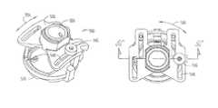
- FIG. 2shows an isometric view of an exemplary embodiment of an insertion guide device.
- FIG. 3Ashows a side view of a portion of an exemplary embodiment of an insertion guide device.
- FIG. 3Bshows a cross section view of a portion of an exemplary embodiment of an insertion guide device.
- FIG. 3Cshows an isometric view of a part of an exemplary embodiment of an insertion guide device.
- FIG. 4shows a side view of an exemplary embodiment of a centering guide.
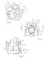
- FIG. 5Ashows an isometric view of a portion of an exemplary embodiment of an insertion guide device.
- FIG. 5Bshows a top view of a portion of an exemplary embodiment of an insertion guide device.
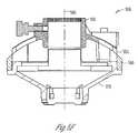
- FIG. 5Cshows a cross section view taken along line 5 C- 5 C of FIG. 5B .
- FIG. 5Dshows a top view of a portion of an exemplary embodiment of an insertion guide device.
- FIG. 5Eshows a cross section view taken along line 5 E- 5 E of FIG. 5D .
- FIG. 5Fshows a cross section view taken along line 5 F- 5 F of FIG. 5D .
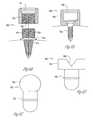
- FIG. 6Ashows a cross section view of a portion of an exemplary embodiment of a fiducial marker.
- FIG. 6Bshows a cross section view of a portion of an exemplary embodiment of a fiducial marker.
- FIG. 6Cshows a portion of an exemplary embodiment of a fiducial marker.
- FIG. 6Dshows a portion of an exemplary embodiment of a fiducial marker.
- FIG. 7shows an isometric view of an exemplary embodiment of an insertion guide device.
- FIG. 8shows an isometric view of an exemplary embodiment of an insertion guide device.
- FIG. 9shows a flow diagram of an exemplary embodiment of a method according to various teachings of the present disclosure.
- FIG. 1shows a subject surface 100 along with one possible coordinate system for defining locations and orientations with respect to the subject.
- the subject surface 100includes a skull of a subject.
- An opening 102 in the subject surfaceis shown, along with a target location 104 within the subject.
- the opening 102includes a burr hole.
- An insertion axis 110is shown that begins outside the subject surface 100 and ends at the target location 104 .
- the insertion axis 110further passes through an insertion point 112 on its way to the target location 104 .
- the insertion point 112is shown substantially within the center of the opening 102 .
- the insertion axis 110can be rotated about the insertion point 112 and further about any of three orthogonal axes that pass through the insertion point 112 . In this way, any orientation of the insertion axis 110 can be selected, while still passing through the insertion point 112 . In one embodiment, rotation about at least two of the three orthogonal axes is used to select an orientation of the insertion axis 110 . Although orthogonal axes are shown, non-orthogonal axes passing through the insertion point are also possible without departing from the scope of the present disclosure.
- a first rotational degree of freedom shown by arrow 122is included.
- the first rotational degree of freedomis used for orienting the insertion axis 110 .
- the first rotational degree of freedomrotates about a first rotational axis 120 that passes through the insertion point 112 .
- the first rotational axis 120is normal to the subject surface 100 at the insertion point 112 .
- a second rotational degree of freedom shown by arrow 132is included.
- the second rotational degree of freedomis used for orienting the insertion axis 110 .
- the second rotational degree of freedomrotates about a second rotational axis 130 that passes through the insertion point 112 .
- the second rotational axis 130is tangent to the subject surface 100 at the insertion point 112 .
- a third rotational degree of freedom shown by arrow 142is included.
- the third rotational degree of freedomis used for orienting the insertion axis 110 .
- the third rotational degree of freedomrotates about a third rotational axis 140 that passes through the insertion point 112 .
- the third rotational axis 140is tangent to the subject surface 100 at the insertion point 112 .
- the first degree of rotational freedom, the second degree of rotational freedom, and the third degree of rotational freedomall leave the location of the insertion point 112 fixed.
- the degrees of rotational freedomrotate about the insertion point 112 because the location of the opening in the subject 102 remains fixed during a surgical procedure.
- a first degree of translational freedomis also included.
- a first degree of translational freedomis defined by the adjustability of the location of the insertion point 112 along direction 114 .
- a second degree of translational freedomis also included where the location of the insertion point 112 is adjustable along direction 116 .
- FIG. 2shows one embodiment of an insertion guide device 200 .
- the insertion guide device 200includes a base unit 210 , and an insertion guide portion 220 coupled to the base unit 210 .
- the insertion guide portion 220determines an insertion axis 222 .
- a number of attachment devices 230are also shown coupled to the base unit 210 .
- the attachment devicesinclude a bone screw 232 .
- the attachment devices 230are coupled to the base unit 210 through a number of insertion point adjustment devices 240 .
- the insertion point adjustment devices 240include a split clamping portion 241 and a screw 242 .
- the insertion point adjustment devices 240allow the base unit to be adjusted with respect to the attachment devices 230 substantially along direction 244 .
- an insertion point adjustment device 240is included for each attachment device 230 .
- the insertion guide device 200includes three attachment devices 230 and three insertion point adjustment devices 240 .
- an insertion point (not shown) of the insertion axis 222is translated through at least one degree of translational freedom to a selected location within the subject surface.
- Three attachment devicesare convenient because they provide the most stable platform with a minimum number of contact points on the subject.
- FIG. 2also shows a first angular adjustment device 250 for adjusting a first rotational degree of freedom.
- the first angular adjustment device 250permits rotation of a component of the insertion axis 222 about a first rotational axis that is substantially normal to the subject surface at the insertion point.
- the rotation of the insertion axis 222 in the first rotational degree of freedomis shown by arrows 254 .
- a locking device 252is shown to secure an orientation of the insertion axis 222 in the first rotational degree of freedom as selected.
- the locking deviceincludes a threaded lock ring.
- a second angular adjustment device 260for adjusting a second rotational degree of freedom.
- the second angular adjustment device 260permits rotation of the insertion axis 222 about the insertion point and further about a second rotational axis.
- the second rotational axisis substantially tangent to the subject surface at the insertion point.
- the second angular adjustment device 260includes a rail 262 that guides the adjustment of the second angular adjustment device 260 .
- a pair of rails 262are used.
- a locking device 264is used to secure an orientation of the insertion axis 222 in the second rotational degree of freedom as selected.
- the locking device 264includes one or more set screws.
- a centering guide 270is further shown in FIG. 2 .
- the centering guideis fixed within the insertion guide portion 220 using a locking device 224 .
- the locking device 224includes one or more set screws. Embodiments of the centering guide are discussed in more detail later in the specification.
- selected elements of an insertion guide devicesuch as insertion guide device 200 are fabricated from a substantially transparent material.
- transparent materialsinclude, but are not limited to, polycarbonate, crystalline polymers, glasses, etc.
- FIG. 3Ashows an embodiment of an attachment device 330 and an insertion point adjustment devices 340 attached to a subject surface 300 .
- the attachment device 330includes a truncated cone portion 334 and a securing device 332 such as a bone screw.
- the insertion point adjustment devices 340includes a threaded portion 341 coupled to a gripping portion 342 .
- the gripping portion 342includes a knurled knob portion.
- the threaded portion 341engages a portion of a base 310 to provide motion of the base 310 substantially along directional arrows 344 with respect to the attachment device 330 .
- FIG. 3Bshows a cross section of the attachment device 330 and an insertion point adjustment devices 340 of FIG. 3A .
- the threaded portion 341 and the gripping portion 342are separately fabricated from the attachment device 330 .
- the threaded portionis rotatably coupled to the attachment device 330 by a retaining device 338 .
- the retaining device 338includes a barb. A rotatably coupled arrangement allows the attachment device 330 to remain substantially fixed while adjustments are made to the threaded portion 341 .
- FIG. 3Cshows an embodiment of an attachment device 350 including a substantially linear contact surface 352 .
- featuressuch as the substantially linear contact surface 352 and the truncated cone portion 334 help to reduce tissue damage due to attachment of the insertion guide device to a subject.
- tissue damageas a result of attachment is an issue.
- tissue damageis reduced by utilizing a minimum number of attachment devices.
- three attachment devicesare used to maintain a stable platform for the insertion guide device while minimizing a number of attachment locations.
- the attachment devicesare located apart from the opening in the subject, such as a burr hole. The more remote location of attachment devices reduces tissue damage at the opening or burr hole location.
- the attachment devicesraise a substantial portion of the insertion guide device above the subject surface. By raising the insertion guide device above the subject surface, tissue damage due to pinching large amounts of tissue under the insertion guide device is avoided.
- the shape of the attachment device or devicesfurther reduces tissue damage.
- the truncated cone shapereduces a subject contact surface to a minimum area where sufficient support for the securing device such as a bone screw is provided, while reducing the contact area.
- a cone shapeis desirable due to the use of a round cutting device to pierce tissue on a subject's scalp prior to attachment.
- a modified hypodermic needleis used to pierce the scalp, thus making a round attachment device convenient.
- a substantially linear contact surfaceis desirable due to the use of a linear cutting instrument to pierce tissue on a subject's scalp prior to attachment.
- a scalpelis used to pierce the scalp, thus making a substantially linear contact surface of an attachment device convenient.
- FIG. 4shows one embodiment of a centering device 470 similar to the embodiment illustrated in FIG. 2 .
- the device configuration and use of a centering deviceis not, however, limited to the embodiment illustrated in FIG. 2 .
- the centering device 470includes an insertion axis 472 , a first diameter portion 474 and a second diameter portion 476 .
- the first diameter portion 474forms a close tolerance fit within an insertion guide portion so that the insertion axis 472 can be adjusted using adjustable features of the insertion guide device embodiments as described above.
- the second diameter portion 476forms a close tolerance fit within an opening in a subject such as a burr hole.
- the second diameter portion 476fits inside an irregular opening in a subject such as a burr hole to effectively find an approximate center of an irregular opening.
- an insertion pointmay not be aligned over the center of a round burr hole, or the effective center of an irregular burr hole.
- the translational location of the insertion pointcan be adjusted using insertion point adjustment devices as described above.
- a centering guidecan be further utilized to indicate to a user when the insertion point is aligned with the center of the opening in the subject. In one embodiment, when the insertion point has been moved such that the second diameter portion 476 fits at least partially within the opening in the subject, the insertion point is aligned with the opening in the subject.
- a centering deviceis used to center an insertion point of an insertion guide device over an opening in a subject prior to attachment of the insertion guide device on the subject.
- the centering deviceallows a fast and efficient location of attachment points for the insertion guide device in embodiments where the location of attachment points has not already been determined.
- FIG. 5Ashows a portion of an insertion guide device 500 .
- attachment devices and insertion point adjustment devices as described aboveare used in conjunction with embodiments described in FIGS. 5A-5C .
- An insertion guide portion 520is shown coupled to a first portion 522 .
- the insertion guide portion 520is further coupled to a second portion 530 .
- the insertion guide portion 520is further coupled to a base portion 510 .
- a first angular adjustment deviceis shown in FIG. 5A that permits rotation adjustment of an insertion axis 502 along direction 524 .
- a second angular adjustment deviceis shown in FIG. 5B that permits rotation adjustment of an insertion axis 502 along direction 526 .
- the portion of an insertion guide device 500includes a locking device 540 that fixes both the first angular adjustment device and the second angular adjustment device concurrently when actuated.
- the locking device 540includes a gripping device 542 such as a knob.
- the locking device 540includes a threaded member 544 coupled to the gripping device 542 .
- the threaded member 544passes through a slot 548 in the first portion 522 , allowing the first portion to move along direction 524 with respect to the body portion 510 .
- the locking device 540includes a base contacting portion 546 .
- the base contacting portion 546can include a contacting lip 547 that extends radially inward ( FIG. 5C ).
- the base portion 510can include a base lip 549 that extends radially outward ( FIG. 5C ) to abut with the contacting lip 547 .
- FIGS. 5A-5Cfixes an orientation of the insertion axis 502 in multiple degrees of freedom concurrently by tightening the threaded member 544 with the gripping portion 542 .
- the threaded memberin turn tightens the base contacting portion 546 against the base 510 .
- This tightening motionpulls the base 510 ; the first portion 522 , and the second portion 530 together, substantially fixing their respective locations.
- Using one locking device 540 to fix multiple adjustment devicesis desirable in one embodiment because it allows a surgeon to quickly and easily secure all movement of an insertion axis 502 in a single locking operation once a desired orientation is found.
- a tradeoffis also present, in that during some operations, precise adjustment requires that each degree of freedom, or angular adjustment is focused on independently. When independent focus on each degree of freedom is necessary, individual angular adjustment and individual locking devices are desirable.
- FIG. 5Dshows a portion of an insertion guide device 550 .
- attachment devices and insertion point adjustment devices as described aboveare used in conjunction with embodiments described in FIGS. 5D-5F .
- An insertion guide portion 551is shown coupled to a first portion 552 .
- the insertion guide portion 551is further coupled to a second portion 560 .
- the insertion guide portion 551is further coupled to a base portion 570 .
- a first angular adjustment deviceis shown in FIG. 5D that permits rotation adjustment of an insertion axis 503 along direction 554 .
- a second angular adjustment deviceis shown in FIG. 5D that permits rotation adjustment of an insertion axis 503 along direction 556 .
- the portion of an insertion guide device 551includes a locking device 580 that fixes both the first angular adjustment device and the second angular adjustment device concurrently when actuated.
- the locking device 580includes a gripping device 582 such as a knob.
- the locking device 580includes a threaded member 584 coupled to the gripping device 582 .
- the threaded member 584passes through a slot 588 in the first portion 552 , allowing the first portion 552 to move along direction 554 with respect to the body portion 570 .
- the locking device 580includes a base contacting portion 586 .
- FIGS. 5D-5Ffixes an orientation of the insertion axis 503 in multiple degrees of freedom concurrently by tightening the threaded member 584 with the gripping portion 582 .
- the threaded memberin turn tightens the base contacting portion 586 against the base 570 .
- This tightening motionpulls the base 570 ; the first portion 552 , and the second portion 560 together, substantially fixing their respective locations.
- the portion of an insertion guide device 551includes a second locking device 590 that fixes both the first angular adjustment device and the second angular adjustment device concurrently when actuated.
- the locking device 590includes a gripping device 592 such as a knob.
- the locking device 590includes a threaded member 594 coupled to the gripping device 592 .
- the threaded member 594passes through a slot 598 in the first portion 552 , allowing the first portion 552 to move along direction 554 with respect to the body portion 570 .
- the locking device 590includes a base contacting portion 596 .
- FIGS. 5D-FOne advantage of designs shown in FIGS. 5D-F includes the ability to quickly and easily secure all movement of an insertion axis 503 in a single locking operation once a desired orientation is found.
- An additional locking device, such as locking device 590provides extra security that the degrees of freedom of the insertion guide device 551 will not accidentally move out of the selected alignment.
- FIGS. 6A-6Dshow a number of embodiments of fiducial markers and portions of fiducial markers according to embodiments of the invention.
- a securing device 610is shown with a subject securing portion 612 , a transition portion 614 , and an upper securing portion 616 .
- the subject securing portionincludes a bone screw portion.
- the upper securing portionincludes a threaded portion.
- the interchange portion 620includes a mating portion 622 that engages the upper securing portion 616 of the securing device 610 .
- the mating portion 622includes a mating threaded portion.
- a holding region 624such as a groove.
- FIG. 6Bshows an embodiment of a portion of a fiducial marker 650 .
- a subject securing device 652such as a more conventional bone screw, is shown attaching an interchange portion 654 to a subject surface. Similar to FIG. 6A , a holding region 656 such as a groove is shown coupled to the interchange portion 654 .
- the use of a more conventional bone screwis more cost effective in manufacturing of the portion of the fiducial marker 650 .
- FIG. 6Cshows an interchangeable indicator 630 .
- the interchangeable indicator 630includes an upper portion 634 that functions to indicate a point location in a medical imaging device such as a CT or MRI device, etc.
- the upper portionreflects a selected wavelength of light that in turn indicates a position of a portion of a subject, using a detection device.
- a mating portion 632is further shown attached to the upper portion 634 .
- the mating portion 632is adapted to be removably positioned within a holding region such as the holding regions 624 and 656 described above.
- FIG. 6Dshows an adaptor device 640 for use with embodiments of the insertion guide device as described above.
- the interchangeable indicator 630is adapted to be removed after initial subject imaging is complete.
- the adaptor device 640may then be inserted into an embodiment of the fiducial markers or portions of fiducial markers as described above.
- the insertion guide deviceis then directly mountable to the fiducial markers or portions of fiducial markers without additional attachments needed. Tissue damage, as discussed above, is reduced using this configuration, as well as increased targeting accuracy due to the use of the exact fiducial locations to mount the insertion guide device.
- the adaptor device 640includes an upper portion 644 with a receiving portion 646 .
- the receiving portionis adapted to couple with attachment devices of insertion guide devices as described above.
- the receiving portionincludes a groove, although the present disclosure is not so limited.
- an adaptor deviceis shown in FIG. 6D for use in coupling an insertion guide device to a number of fiducial markers or portions of a number of fiducial markers, the present disclosure is not so limited.
- the insertion guide devicemay also be directly attached to a number of fiducial markers or portions of a number of fiducial markers directly without use of an adaptor device.
- FIG. 7shows an embodiment of an insertion guide device 700 .
- the insertion guide device 700includes a base unit 710 , and an insertion guide portion 720 coupled to the base unit 710 .
- the insertion guide portion 720determines an insertion axis similar to embodiments shown above.
- a number of attachment devices 730are also shown coupled to the base unit 710 .
- the attachment devices 730are coupled to the base unit 710 through a number of insertion point adjustment devices 740 .
- the insertion point adjustment devices 740include a split clamping portion 741 and a screw 742 .
- the insertion point adjustment devices 740allow the base unit 710 to be adjusted with respect to the attachment devices 730 similar to embodiments discussed above.
- an insertion point adjustment device 740is included for each attachment device 730 .
- the insertion guide device 700includes three attachment devices 730 and three insertion point adjustment devices 740 .
- an insertion point(not shown) is translated through at least one degree of translational freedom to a selected location within the subject surface.
- FIG. 7also shows a first angular adjustment device 750 for adjusting a first rotational degree of freedom.
- the first angular adjustment device 750permits rotation of a component of the insertion axis about a first rotational axis.
- the first rotational axisis substantially tangent to the subject surface at the insertion point.
- at least one rail 752guides the insertion guide portion 720 along the first rotational degree of freedom.
- a locking device 754is shown to secure an orientation of the insertion axis in the first rotational degree of freedom as selected.
- the locking deviceincludes at least one set screw.
- FIG. 7also shows a second angular adjustment device 760 for adjusting a second rotational degree of freedom.
- the second angular adjustment device 760permits rotation of a component of the insertion axis about a second rotational axis.
- the second rotational axisis substantially tangent to the subject surface at the insertion point.
- at least one rail 762guides the insertion guide portion 720 along the second rotational degree of freedom.
- a locking device 764is shown to secure an orientation of the insertion axis in the first rotational degree of freedom as selected.
- the locking deviceincludes at least one set screw.
- FIG. 7also shows a third angular adjustment device 716 for adjusting a third rotational degree of freedom.
- the third angular adjustment device 716permits rotation of a component of the insertion axis about a third rotational axis.
- the third rotational axisis substantially normal to the subject surface at the insertion point.
- a rotating body portion 712is allowed to rotate with respect to the body 710 .
- a locking device 714is shown to secure an orientation of the insertion axis in the third rotational degree of freedom as selected.
- the locking deviceincludes at least one set screw.
- the insertion guide portion 720includes a locking device 722 .
- the locking device 722includes a knob attached to a threaded portion that bears down against a back plate 724 .
- at least two of the rotational degrees of freedom of the insertion guide device 700can be concurrently fixed using the locking device 722 .
- the first rotational degree of freedom and the second rotational degree of freedomcan be concurrently fixed using the locking device 722 .
- FIG. 7shows an embodiment where the rails 752 and rails 762 are fixed between the locking device 722 and the back plate 724 upon actuation of the locking device 722 .
- FIG. 8shows one embodiment of an insertion guide device 800 .
- the insertion guide device 800includes a base unit 810 , and an insertion guide portion 820 coupled to the base unit 810 .
- the insertion guide portion 820determines an insertion axis 802 similar to embodiments shown above.
- a number of attachment devices 830are also shown coupled to the base unit 810 .
- the attachment devices 830include a bone screw 832 .
- the attachment devices 830are coupled to the base unit 810 through a number of insertion point adjustment devices 840 .
- the insertion point adjustment devices 840include a split clamping portion and a screw 842 .
- the insertion point adjustment devices 840allow the base unit 810 to be adjusted with respect to the attachment devices 830 similar to embodiments discussed above. In one embodiment, the insertion point adjustment devices 840 allow the base unit 810 to be adjusted with respect to the attachment devices 830 substantially along direction 844 . In one embodiment an insertion point adjustment device 840 is included for each attachment device 830 . In one embodiment, the insertion guide device 800 includes three attachment devices 830 and three insertion point adjustment devices 840 .
- an insertion point 804is translated through at least one degree of translational freedom to a selected location within the subject surface.
- the insertion point 804is adjustable in both an X-axis and a Y-axis as shown by coordinate axes 806 .
- the insertion guide device 800does not include any adjustment about rotational degrees of freedom as described above.
- an orientation of the insertion axis 802is pre-determined upon fabrication of the body 810 and the insertion guide portion 820 .
- the insertion guide device 800is custom fabricated using stereolithography rapid prototyping or other suitable custom fabrication techniques.
- FIG. 9shows a flow diagram of one method of aligning an insertion guide using embodiments of the invention as described above.
- fiducial markersare first installed on a subject, such as a surgical patient.
- the subjectis then imaged using imaging techniques as described above, such as CT or MRI techniques, etc.
- An imageis generated of the subject with tissue shown in relation to the fiducial markers, which are concurrently imaged using the selected imaging technique.
- the target location within the subjectis determined, and a trajectory is computed between a location external to the subject, to the target location.
- an embodiment of an insertion guide deviceis then adjusted using degrees of freedom as described in embodiments above, to substantially coincide with the computed trajectory in relation to the fiducial markers.
- attachment devices and corresponding insertion point adjustment devicesare asymmetrically spaced about a circumference of the base unit of the insertion guide device to provide easy orientation of the insertion guide on the fiducial markers.
- the insertion guide deviceis then attached to the fiducial markers in a state of substantial alignment with the desired trajectory as determined by imaging.
- One advantage of a method as described aboveis that substantial alignment of the insertion guide is possible without the subject being present. This allows time in the operating room to be reduced.
- alignment of the insertion guidecan be performed on the subject. Although substantial alignment of the insertion guide device can be accomplished without the subject being present, it is sometimes necessary to perform fine adjustment with the insertion guide device attached on the subject. As described previously, variations in mounting an insertion guide device or opening a burr hole can make fine adjustments necessary.
- an insertion guidehas been shown that includes at least one insertion point adjustment device.
- a usersuch as a surgeon is able to adjust a lateral position of an insertion point to more precisely center the insertion point within an opening in a subject, such as a burr hole.
- Selected embodiments described abovefurther include a centering guide that easily indicates to a user when the insertion point is substantially centered within the opening in the subject.
- Selected embodiments described abovefurther include adjustments of rotational degrees of freedom of an insertion axis. These adjustments allow a user to align the insertion axis with a target location within a subject, without changing the lateral (translational) location of the insertion point. Selected embodiments described above permit a user to fix multiple degrees of rotational freedom using a single locking device.
- Selected embodiments described abovefurther include the ability to attach an insertion guide device to at least one existing fiducial marker.
- the ability to attach to a fiducial markerimproves accuracy of the insertion guide device by aligning more precisely with imaged locations on a subject, and tissue damage or other attachment surface damage is reduced by eliminating a separate attachment procedure for the insertion guide device, apart from the attachment of the fiducial markers.
- Selected embodiments described abovefurther include attachment of a large percentage of an insertion guide device at a distance above a subject surface. Reducing a contact surface area reduces tissue damage or other attachment surface damage due to an attachment procedure. Embodiments utilizing substantially transparent materials increase viewability of an opening in a subject.
Landscapes
- Health & Medical Sciences (AREA)
- Surgery (AREA)
- Life Sciences & Earth Sciences (AREA)
- Molecular Biology (AREA)
- General Health & Medical Sciences (AREA)
- Oral & Maxillofacial Surgery (AREA)
- Engineering & Computer Science (AREA)
- Biomedical Technology (AREA)
- Heart & Thoracic Surgery (AREA)
- Medical Informatics (AREA)
- Nuclear Medicine, Radiotherapy & Molecular Imaging (AREA)
- Animal Behavior & Ethology (AREA)
- Pathology (AREA)
- Public Health (AREA)
- Veterinary Medicine (AREA)
- Surgical Instruments (AREA)
- Vehicle Body Suspensions (AREA)
- Diaphragms For Electromechanical Transducers (AREA)
- Radiation-Therapy Devices (AREA)
- Body Structure For Vehicles (AREA)
- Seal Device For Vehicle (AREA)
- Instruments For Viewing The Inside Of Hollow Bodies (AREA)
Abstract
Description
Claims (18)
Priority Applications (1)
| Application Number | Priority Date | Filing Date | Title |
|---|---|---|---|
| US12/615,182US8116850B2 (en) | 2002-12-20 | 2009-11-09 | Organ access device and method |
Applications Claiming Priority (2)
| Application Number | Priority Date | Filing Date | Title |
|---|---|---|---|
| US10/325,615US7636596B2 (en) | 2002-12-20 | 2002-12-20 | Organ access device and method |
| US12/615,182US8116850B2 (en) | 2002-12-20 | 2009-11-09 | Organ access device and method |
Related Parent Applications (1)
| Application Number | Title | Priority Date | Filing Date |
|---|---|---|---|
| US10/325,615ContinuationUS7636596B2 (en) | 2002-12-20 | 2002-12-20 | Organ access device and method |
Publications (2)
| Publication Number | Publication Date |
|---|---|
| US20100057008A1 US20100057008A1 (en) | 2010-03-04 |
| US8116850B2true US8116850B2 (en) | 2012-02-14 |
Family
ID=32593828
Family Applications (2)
| Application Number | Title | Priority Date | Filing Date |
|---|---|---|---|
| US10/325,615Expired - LifetimeUS7636596B2 (en) | 2002-12-20 | 2002-12-20 | Organ access device and method |
| US12/615,182Expired - Fee RelatedUS8116850B2 (en) | 2002-12-20 | 2009-11-09 | Organ access device and method |
Family Applications Before (1)
| Application Number | Title | Priority Date | Filing Date |
|---|---|---|---|
| US10/325,615Expired - LifetimeUS7636596B2 (en) | 2002-12-20 | 2002-12-20 | Organ access device and method |
Country Status (6)
| Country | Link |
|---|---|
| US (2) | US7636596B2 (en) |
| EP (1) | EP1575440B1 (en) |
| AT (1) | ATE390894T1 (en) |
| AU (1) | AU2003297393A1 (en) |
| DE (1) | DE60320136T2 (en) |
| WO (1) | WO2004058086A1 (en) |
Cited By (13)
| Publication number | Priority date | Publication date | Assignee | Title |
|---|---|---|---|---|
| US20100179563A1 (en)* | 2002-09-17 | 2010-07-15 | Medtronic, Inc. | Low Profile Instrument Immobilizer |
| US20110022058A1 (en)* | 2000-04-07 | 2011-01-27 | Medtronic, Inc. | Device for Immobilizing a Primary Instrument and Method Therefor |
| US20110034981A1 (en)* | 2004-02-13 | 2011-02-10 | Medtronic, Inc. | Apparatus for Securing a Therapy Delivery Device Within a Burr Hole and Method for Making Same |
| US9161799B2 (en) | 2013-01-28 | 2015-10-20 | Warsaw Orthopedic, Inc. | Surgical implant system and method |
| US9545509B2 (en) | 2010-12-03 | 2017-01-17 | Neuropace, Inc. | Lead fixation device for securing a medical lead in a human patient |
| US9572973B2 (en) | 2013-03-10 | 2017-02-21 | Neuropace, Inc. | Recessed burr hole covers and methods for using the same |
| US9788952B2 (en) | 2012-05-10 | 2017-10-17 | Neuropace, Inc. | Burr hole covers and methods for using same |
| US9867673B2 (en) | 2015-07-14 | 2018-01-16 | Canon U.S.A, Inc. | Medical support device |
| US10285670B2 (en) | 2014-09-12 | 2019-05-14 | Canon U.S.A., Inc. | Needle positioning apparatus |
| US10543360B2 (en) | 2017-09-29 | 2020-01-28 | Neuropace, Inc. | Lead fixation accessory, lead stabilization tool, and related procedures |
| US11458302B2 (en) | 2019-12-04 | 2022-10-04 | Neuropace, Inc. | Hinged lead fixation devices for securing a lead to a cranium |
| US11547850B2 (en) | 2018-11-29 | 2023-01-10 | Neuropace, Inc. | Lead fixation devices for securing a lead to a cranium |
| US11842030B2 (en) | 2017-01-31 | 2023-12-12 | Medtronic Navigation, Inc. | Method and apparatus for image-based navigation |
Families Citing this family (91)
| Publication number | Priority date | Publication date | Assignee | Title |
|---|---|---|---|---|
| US8256430B2 (en) | 2001-06-15 | 2012-09-04 | Monteris Medical, Inc. | Hyperthermia treatment and probe therefor |
| DE10154163A1 (en) | 2001-11-03 | 2003-05-22 | Advanced Med Tech | Device for straightening and stabilizing the spine |
| FR2839440B1 (en) | 2002-05-13 | 2005-03-25 | Perception Raisonnement Action | POSITIONING SYSTEM ON A PATIENT OF AN OBSERVATION AND / OR INTERVENTION DEVICE |
| US7479146B2 (en)* | 2002-08-14 | 2009-01-20 | Boston Scientific Neuromodulation Corporation | Cranial burr hole plug and insertion tool |
| ES2288335B1 (en)* | 2004-11-04 | 2008-11-16 | Instituto Cientifico Y Tecnologico De Navarra, S.A. | SUPPORT TO STRENGTHEN A SURGICAL TOOL. |
| DE102005047527A1 (en)* | 2005-10-04 | 2007-04-05 | Rheinisch-Westfälisch Technische Hochschule Aachen | Trocar sleeve retaining device for minimal invasive surgery such as laproscopy, has retaining arms whose one end is arranged on retainer and another end is supported at surgery region such as skin of patient |
| CA2623616A1 (en) | 2005-11-29 | 2007-06-07 | Surgi-Vision, Inc. | Mri-guided localization and/or lead placement systems, related methods, devices and computer program products |
| CA2721367A1 (en)* | 2006-03-07 | 2008-04-24 | Hirdesh Sahni | Image guided stereotactic needle placement device |
| EP2051644A4 (en)* | 2006-08-01 | 2013-03-13 | Eon Surgical Ltd | System and method for telesurgery |
| US8979931B2 (en) | 2006-12-08 | 2015-03-17 | DePuy Synthes Products, LLC | Nucleus replacement device and method |
| CN101801301B (en)* | 2007-06-07 | 2013-09-25 | 核磁共振成像介入技术有限公司 | Mri-guided medical interventional systems and methods |
| US8175677B2 (en) | 2007-06-07 | 2012-05-08 | MRI Interventions, Inc. | MRI-guided medical interventional systems and methods |
| US8315689B2 (en) | 2007-09-24 | 2012-11-20 | MRI Interventions, Inc. | MRI surgical systems for real-time visualizations using MRI image data and predefined data of surgical tools |
| CA2700523A1 (en) | 2007-09-24 | 2009-04-02 | Surgivision, Inc. | Mri-guided medical interventional systems and methods |
| US20090088789A1 (en) | 2007-09-28 | 2009-04-02 | O'neil Michael J | Balloon With Shape Control For Spinal Procedures |
| BRPI0818608A2 (en) | 2007-10-05 | 2015-04-22 | Synthes Gmbh | Sequential directional dilatation system for dilating from a nerve of a patient's anatomy, and method for forming an access opening through a psoas muscle to a patient's spine using a dilatation system |
| WO2009067205A1 (en) | 2007-11-21 | 2009-05-28 | Surgi-Vision, Inc. | Methods, systems and computer program products for positioning a guidance apparatus relative to a patient |
| US8728092B2 (en) | 2008-08-14 | 2014-05-20 | Monteris Medical Corporation | Stereotactic drive system |
| US8747418B2 (en) | 2008-08-15 | 2014-06-10 | Monteris Medical Corporation | Trajectory guide |
| DE102008051111B4 (en)* | 2008-10-09 | 2013-01-24 | Reiner Kunz | Holding and guiding device for an endoscopic instrument |
| USD642209S1 (en)* | 2008-11-14 | 2011-07-26 | Applied Materials, Inc. | Alignment button |
| KR101017908B1 (en)* | 2008-12-29 | 2011-03-04 | 한국과학기술연구원 | Electrophoretic Micro Manipulator for Brain Neural Signal Measurement |
| US9232977B1 (en)* | 2009-03-27 | 2016-01-12 | Tausif-Ur Rehman | Instrument guiding device |
| EP2595560A1 (en) | 2010-07-23 | 2013-05-29 | Ecole Polytechnique Federale De Lausanne (EPFL) EPFL-TTO | Adjustable fixation system for neurosurgical devices |
| AU2011305508B2 (en) | 2010-09-21 | 2015-07-09 | The Johns Hopkins University | Method and apparatus for cochlear implant surgery |
| US20120095498A1 (en)* | 2010-10-13 | 2012-04-19 | Ethicon Endo-Surgery, Inc. | Methods and devices for mechanical space creation at a surgical site |
| US8603078B2 (en) | 2010-10-13 | 2013-12-10 | Ethicon Endo-Surgery, Inc. | Methods and devices for guiding and supporting surgical instruments |
| CN101991464B (en)* | 2010-12-02 | 2013-06-19 | 陈祎招 | Minimally invasive brain surgery cannula and/or endoscope fixer |
| US9855405B2 (en)* | 2011-04-29 | 2018-01-02 | Medtronic, Inc. | Burr hole cap assembly with therapy delivery member orientation feature |
| US8961610B2 (en)* | 2011-09-13 | 2015-02-24 | Boston Scientific Neuromodulation Corporation | Fastener holding tool for a cranial burr hole plug |
| US9622779B2 (en) | 2011-10-27 | 2017-04-18 | DePuy Synthes Products, Inc. | Method and devices for a sub-splenius / supra-levator scapulae surgical access technique |
| US9808232B2 (en) | 2011-11-01 | 2017-11-07 | DePuy Synthes Products, Inc. | Dilation system |
| JP6220345B2 (en)* | 2011-12-05 | 2017-10-25 | コーニンクレッカ フィリップス エヌ ヴェKoninklijke Philips N.V. | Surgical tool positioning and orientation during patient-specific port placement |
| US9265490B2 (en) | 2012-04-16 | 2016-02-23 | DePuy Synthes Products, Inc. | Detachable dilator blade |
| US9498297B2 (en)* | 2012-04-18 | 2016-11-22 | United Arab Emirates University | Manipulator for surgical tools |
| EP2866723A4 (en) | 2012-06-27 | 2016-12-14 | Monteris Medical Corp | GUIDED THERAPY BY IMAGE OF A FABRIC |
| US9192446B2 (en) | 2012-09-05 | 2015-11-24 | MRI Interventions, Inc. | Trajectory guide frame for MRI-guided surgeries |
| US9480855B2 (en) | 2012-09-26 | 2016-11-01 | DePuy Synthes Products, Inc. | NIR/red light for lateral neuroprotection |
| US9352125B2 (en) | 2013-03-12 | 2016-05-31 | Medtronic, Inc. | Portal anchors incorporating strain relief cup and systems using same |
| US9302043B2 (en) | 2013-03-12 | 2016-04-05 | Medtronic, Inc. | Socketed portal anchors and methods of using same |
| US10252032B2 (en) | 2013-03-12 | 2019-04-09 | Medtronic, Inc. | Socketed portal anchors and methods of using same |
| US10274553B2 (en) | 2013-03-15 | 2019-04-30 | Canon U.S.A., Inc. | Needle placement manipulator with attachment for RF-coil |
| WO2015030671A1 (en)* | 2013-08-28 | 2015-03-05 | Institute Of Technical Education | System and apparatus for guiding an instrument |
| JP6467434B2 (en) | 2014-02-27 | 2019-02-13 | ザ ブリガム アンド ウィメンズ ホスピタル インコーポレイテッドThe Brigham and Women’s Hospital, Inc. | Mounting device |
| US20150265353A1 (en) | 2014-03-18 | 2015-09-24 | Monteris Medical Corporation | Image-guided therapy of a tissue |
| US10675113B2 (en) | 2014-03-18 | 2020-06-09 | Monteris Medical Corporation | Automated therapy of a three-dimensional tissue region |
| US9433383B2 (en) | 2014-03-18 | 2016-09-06 | Monteris Medical Corporation | Image-guided therapy of a tissue |
| US10251670B2 (en) | 2014-05-09 | 2019-04-09 | Canon U.S.A., Inc. | Positioning apparatus |
| US9980737B2 (en) | 2014-08-04 | 2018-05-29 | Medos International Sarl | Flexible transport auger |
| US9924979B2 (en)* | 2014-09-09 | 2018-03-27 | Medos International Sarl | Proximal-end securement of a minimally invasive working channel |
| US10264959B2 (en) | 2014-09-09 | 2019-04-23 | Medos International Sarl | Proximal-end securement of a minimally invasive working channel |
| US10111712B2 (en) | 2014-09-09 | 2018-10-30 | Medos International Sarl | Proximal-end securement of a minimally invasive working channel |
| US20160166355A1 (en)* | 2014-11-06 | 2016-06-16 | Alpha Omega Neuro Technologies Ltd. | System and method for co-registering a stereotactic frame and a fiducial |
| US10786264B2 (en) | 2015-03-31 | 2020-09-29 | Medos International Sarl | Percutaneous disc clearing device |
| US10327830B2 (en) | 2015-04-01 | 2019-06-25 | Monteris Medical Corporation | Cryotherapy, thermal therapy, temperature modulation therapy, and probe apparatus therefor |
| US20180191482A1 (en)* | 2015-06-17 | 2018-07-05 | Nokia Solutions And Networks Oy | Adjacent frequency bands |
| US10076387B2 (en) | 2015-06-18 | 2018-09-18 | Medtronic, Inc. | Medical device implantation and positioning system |
| US10639065B2 (en) | 2015-07-21 | 2020-05-05 | Canon U.S.A., Inc. | Medical assist device |
| US10232169B2 (en) | 2015-07-23 | 2019-03-19 | Boston Scientific Neuromodulation Corporation | Burr hole plugs for electrical stimulation systems and methods of making and using |
| US10987129B2 (en) | 2015-09-04 | 2021-04-27 | Medos International Sarl | Multi-shield spinal access system |
| US11672562B2 (en) | 2015-09-04 | 2023-06-13 | Medos International Sarl | Multi-shield spinal access system |
| US12150636B2 (en) | 2015-09-04 | 2024-11-26 | Medos International Sárl | Surgical instrument connectors and related methods |
| US11439380B2 (en) | 2015-09-04 | 2022-09-13 | Medos International Sarl | Surgical instrument connectors and related methods |
| CN113143355A (en) | 2015-09-04 | 2021-07-23 | 美多斯国际有限公司 | Multi-shield spinal access system |
| US11744447B2 (en) | 2015-09-04 | 2023-09-05 | Medos International | Surgical visualization systems and related methods |
| US10702257B2 (en)* | 2015-09-29 | 2020-07-07 | Ethicon Llc | Positioning device for use with surgical instruments |
| USD788300S1 (en)* | 2015-10-27 | 2017-05-30 | Orthogrid Systems, Inc. | Grid positioning device |
| WO2017132505A1 (en) | 2016-01-29 | 2017-08-03 | Canon U.S.A., Inc. | Tool placement manipulator |
| US10299838B2 (en) | 2016-02-05 | 2019-05-28 | Medos International Sarl | Method and instruments for interbody fusion and posterior fixation through a single incision |
| EP3261572B1 (en)* | 2016-05-20 | 2018-08-01 | Brainlab AG | Tracking reference fixation support |
| JP6948389B2 (en)* | 2016-10-19 | 2021-10-13 | キヤノン ユーエスエイ, インコーポレイテッドCanon U.S.A., Inc | Placement manipulators and attachments for positioning puncture devices |
| US9707049B1 (en)* | 2016-12-22 | 2017-07-18 | The Florida International University Board Of Trustees | Stereotactic device for implantation of permanent implants into a rodent brain |
| US10905497B2 (en) | 2017-04-21 | 2021-02-02 | Clearpoint Neuro, Inc. | Surgical navigation systems |
| US11096758B2 (en) | 2017-05-23 | 2021-08-24 | Boston Scientific Limited | Surgical guidance systems, devices, and methods |
| JP2021502215A (en) | 2017-11-13 | 2021-01-28 | ボストン サイエンティフィック ニューロモデュレイション コーポレイション | Systems and methods for manufacturing and using flat control modules for electrical stimulation systems |
| US11497914B2 (en) | 2018-01-16 | 2022-11-15 | Boston Scientific Neuromodulation Corporation | Systems and methods for making and using an electrical stimulation system with a case-neutral battery |
| US11058870B2 (en) | 2018-03-09 | 2021-07-13 | Boston Scientific Neuromodulation Corporation | Burr hole plugs for electrical stimulation systems and methods of making and using |
| JP6398028B1 (en)* | 2018-03-13 | 2018-09-26 | 公立大学法人奈良県立医科大学 | Puncture needle holder |
| EP3765142B1 (en) | 2018-03-16 | 2022-05-04 | Boston Scientific Neuromodulation Corporation | Kit for securing burr hole plugs for stimulation systems |
| US10251722B1 (en) | 2018-09-17 | 2019-04-09 | The Florida International University Board Of Trustees | Stereotaxic brain implant system for large animals |
| US11013530B2 (en) | 2019-03-08 | 2021-05-25 | Medos International Sarl | Surface features for device retention |
| US11241252B2 (en) | 2019-03-22 | 2022-02-08 | Medos International Sarl | Skin foundation access portal |
| US11129727B2 (en) | 2019-03-29 | 2021-09-28 | Medos International Sari | Inflatable non-distracting intervertebral implants and related methods |
| US11813026B2 (en) | 2019-04-05 | 2023-11-14 | Medos International Sarl | Systems, devices, and methods for providing surgical trajectory guidance |
| CN112244753B (en)* | 2020-11-02 | 2021-04-30 | 康年医疗科技有限公司 | Laparoscope lens fixing equipment |
| CN112568949B (en)* | 2020-12-23 | 2022-11-01 | 南京瑞淇卓越医疗美容诊所有限公司 | A pneumoperitoneum needle puncture device for laparoscopic surgery |
| EP4039216A1 (en)* | 2021-02-05 | 2022-08-10 | Metal Aarschot NV | Instrument holder |
| US11771517B2 (en) | 2021-03-12 | 2023-10-03 | Medos International Sarl | Camera position indication systems and methods |
| US20220346831A1 (en)* | 2021-03-25 | 2022-11-03 | Shaw P. Wan | Imaging needle guide |
| WO2025049776A1 (en)* | 2023-08-30 | 2025-03-06 | Glenoid Solutions, LLC | Adjustable surgical guide, virtual planning, and surgical navigation of same |
| US11871942B1 (en)* | 2023-08-30 | 2024-01-16 | Glenoid Solutions, LLC | Adjustable surgical guide |
Citations (284)
| Publication number | Priority date | Publication date | Assignee | Title |
|---|---|---|---|---|
| US431187A (en) | 1890-04-29 | 1890-07-01 | Hub-attaching device | |
| US438801A (en) | 1890-10-21 | Bung and bushing | ||
| US873009A (en) | 1907-04-08 | 1907-12-10 | Frederic Baxter | Belt-fastener. |
| US1129333A (en) | 1914-06-27 | 1915-02-23 | Robert Henry Clarke | Stereotaxic apparatus. |
| US1664210A (en) | 1923-07-16 | 1928-03-27 | Gen Electric | Vibration recorder |
| US2119649A (en) | 1938-06-07 | Sound producer | ||
| US2135160A (en) | 1936-10-23 | 1938-11-01 | Solvay Process Co | Prevention of corrosion |
| US2497820A (en) | 1945-05-01 | 1950-02-14 | Shawinigan Water & Power Co | Cable clamp |
| US2686890A (en) | 1946-01-15 | 1954-08-17 | Us Navy | Klystron tuner |
| US3010347A (en) | 1959-03-18 | 1961-11-28 | Kron Saul | Spanner wrench |
| US3016899A (en) | 1958-11-03 | 1962-01-16 | Carl B Stenvall | Surgical instrument |
| US3017887A (en) | 1960-01-19 | 1962-01-23 | William T Heyer | Stereotaxy device |
| US3055370A (en) | 1958-11-28 | 1962-09-25 | William W Mckinney | Pallidotomy surgical instrument |
| US3055371A (en) | 1958-12-23 | 1962-09-25 | Kulick George | Device for regulation and control of esophago-gastric balloons |
| US3115140A (en) | 1960-08-18 | 1963-12-24 | Baltimore Instr Company | Apparatus for stereotaxic brain operations |
| US3135263A (en) | 1960-10-05 | 1964-06-02 | Smiths America Corp | Surgical instrument positioning device |
| US3223087A (en) | 1960-06-18 | 1965-12-14 | Chirana Praha Np | Stereotaxic device |
| US3262452A (en) | 1963-04-17 | 1966-07-26 | Hardy Wayne | Goniometer apparatus for brain surgery |
| US3273559A (en) | 1963-08-28 | 1966-09-20 | Conductron Corp | Method and apparatus for monitoring the approach of birth |
| US3282152A (en) | 1964-04-15 | 1966-11-01 | Jon H Myer | Signalment recording apparatus |
| US3402710A (en) | 1966-06-27 | 1968-09-24 | Hydra Power Corp | Self-closing valve device for implantation in the human body |
| US3444861A (en) | 1966-03-15 | 1969-05-20 | Rudolf R Schulte | Drain tube with adjusting friction lock |
| US3457922A (en) | 1966-12-13 | 1969-07-29 | Charles D Ray | Stereotaxic surgical instrument and method |
| US3460537A (en) | 1966-09-26 | 1969-08-12 | Donald C Zeis | Stereotactic guide for use in the creation of destructive brain lesions |
| US3508552A (en) | 1961-10-27 | 1970-04-28 | Alexandre & Cie | Apparatus for stereotaxic neurosurgery |
| US3672352A (en) | 1969-04-09 | 1972-06-27 | George D Summers | Implantable bio-data monitoring method and apparatus |
| US3760811A (en) | 1970-01-20 | 1973-09-25 | D Andrew | Endotracheal tube clamp |
| US3817249A (en) | 1972-04-07 | 1974-06-18 | Neuro Probe Inc | Stereotaxic instrument |
| US3893449A (en) | 1973-12-21 | 1975-07-08 | Nasa | Reference apparatus for medical ultrasonic transducer |
| US3981079A (en) | 1973-08-23 | 1976-09-21 | Lenczycki Joseph J | Dental implant and method of mounting the same in the jaw bone |
| US4013080A (en) | 1974-10-03 | 1977-03-22 | Froning Edward C | Cannula connector and direction indicator means for injection system |
| US4026276A (en) | 1976-04-05 | 1977-05-31 | The Johns Hopkins University | Intracranial pressure monitor |
| US4040427A (en) | 1976-04-01 | 1977-08-09 | The Kendall Company | Catheter support assembly |
| US4131257A (en) | 1977-11-14 | 1978-12-26 | Eby Company | Stacking cable clamp |
| US4230117A (en) | 1978-02-27 | 1980-10-28 | Anichkov Andrei D | Stereotaxic apparatus |
| US4265252A (en) | 1978-04-19 | 1981-05-05 | The Johns Hopkins University | Intracranial pressure implant |
| US4312337A (en) | 1980-09-08 | 1982-01-26 | Donohue Brian T | Cannula and drill guide apparatus |
| US4318401A (en) | 1980-04-24 | 1982-03-09 | President And Fellows Of Harvard College | Percutaneous vascular access portal and catheter |
| US4328813A (en) | 1980-10-20 | 1982-05-11 | Medtronic, Inc. | Brain lead anchoring system |
| US4341220A (en) | 1979-04-13 | 1982-07-27 | Pfizer Inc. | Stereotactic surgery apparatus and method |
| US4345606A (en) | 1977-12-13 | 1982-08-24 | Littleford Philip O | Split sleeve introducers for pacemaker electrodes and the like |
| US4350159A (en) | 1980-02-29 | 1982-09-21 | Gouda Kasim I | Frame for stereotactic surgery |
| US4355645A (en) | 1978-10-18 | 1982-10-26 | Kabushiki Kaisha Morita Seisakusho | Device for displaying masticatory muscle activities |
| US4386602A (en) | 1977-05-17 | 1983-06-07 | Sheldon Charles H | Intracranial surgical operative apparatus |
| US4418894A (en) | 1980-11-17 | 1983-12-06 | Paul Wurth S.A. | Furnace taphole drilling apparatus and method |
| DE3108766C2 (en) | 1981-03-07 | 1983-12-15 | GMS, Gesellschaft für medizinische Sondentechnik mbH, 2300 Kiel | Medical stick probe measuring device |
| US4448195A (en) | 1981-05-08 | 1984-05-15 | Leveen Harry H | Reinforced balloon catheter |
| US4463758A (en) | 1981-09-18 | 1984-08-07 | Arun A. Patil | Computed tomography stereotactic frame |
| US4475550A (en) | 1982-03-30 | 1984-10-09 | Bremer Orthopedics, Inc. | Halo for stereotaxic applications |
| US4483344A (en) | 1980-12-30 | 1984-11-20 | Atkov Oleg J | Device for positioning cardiographic sensor |
| US4572198A (en) | 1984-06-18 | 1986-02-25 | Varian Associates, Inc. | Catheter for use with NMR imaging systems |
| US4571750A (en) | 1984-02-21 | 1986-02-25 | The University Of Michigan | Acoustic myography |
| US4579120A (en) | 1982-09-30 | 1986-04-01 | Cordis Corporation | Strain relief for percutaneous lead |
| US4592352A (en) | 1984-11-30 | 1986-06-03 | Patil Arun A | Computer-assisted tomography stereotactic system |
| US4598708A (en) | 1984-09-17 | 1986-07-08 | Cordis Corporation | Torque clamp for use with pervenous lead having fixation device |
| US4608977A (en) | 1979-08-29 | 1986-09-02 | Brown Russell A | System using computed tomography as for selective body treatment |
| US4618978A (en) | 1983-10-21 | 1986-10-21 | Cosman Eric R | Means for localizing target coordinates in a body relative to a guidance system reference frame in any arbitrary plane as viewed by a tomographic image through the body |
| US4617925A (en) | 1984-10-01 | 1986-10-21 | Laitinen Lauri V | Adapter for definition of the position of brain structures |
| US4629451A (en) | 1985-09-23 | 1986-12-16 | Victory Engineering Corp. | Stereotaxic array plug |
| US4638798A (en) | 1980-09-10 | 1987-01-27 | Shelden C Hunter | Stereotactic method and apparatus for locating and treating or removing lesions |
| US4660563A (en) | 1984-12-31 | 1987-04-28 | Massachusetts Institute Of Technology | Method and means for detection of arterial lesions |
| US4665928A (en) | 1983-08-10 | 1987-05-19 | Orthotronics, Inc. | Range of motion measuring and displaying device |
| US4699616A (en) | 1986-06-13 | 1987-10-13 | Hollister Incorporated | Catheter retention device and method |
| US4705436A (en) | 1985-06-06 | 1987-11-10 | Channelwood Preservations Ltd. | Drill jig |
| US4706665A (en) | 1984-12-17 | 1987-11-17 | Gouda Kasim I | Frame for stereotactic surgery |
| US4733661A (en) | 1987-04-27 | 1988-03-29 | Palestrant Aubrey M | Guidance device for C.T. guided drainage and biopsy procedures |
| US4755642A (en) | 1986-07-07 | 1988-07-05 | Iowa State University Research Foundation, Inc. | Switching device |
| US4791934A (en) | 1986-08-07 | 1988-12-20 | Picker International, Inc. | Computer tomography assisted stereotactic surgery system and method |
| US4793355A (en) | 1987-04-17 | 1988-12-27 | Biomagnetic Technologies, Inc. | Apparatus for process for making biomagnetic measurements |
| US4798208A (en) | 1987-12-09 | 1989-01-17 | Faasse Jr Adrian L | Diagnostic electrode |
| US4805615A (en) | 1985-07-02 | 1989-02-21 | Carol Mark P | Method and apparatus for performing stereotactic surgery |
| US4805634A (en) | 1986-06-06 | 1989-02-21 | Hellige Gmbh | Adapter assembly for use with a cranial biosensor |
| US4807620A (en) | 1987-05-22 | 1989-02-28 | Advanced Interventional Systems, Inc. | Apparatus for thermal angioplasty |
| US4809694A (en) | 1987-05-19 | 1989-03-07 | Ferrara Vincent L | Biopsy guide |
| US4824436A (en) | 1985-04-09 | 1989-04-25 | Harvey Wolinsky | Method for the prevention of restenosis |
| US4826487A (en) | 1987-05-04 | 1989-05-02 | Victory Engineering Company | Alignment button for stereotaxic plug and method of using the same |
| US4869247A (en) | 1988-03-11 | 1989-09-26 | The University Of Virginia Alumni Patents Foundation | Video tumor fighting system |
| US4883053A (en) | 1987-09-18 | 1989-11-28 | Beth Israel Hospital | Self-supporting angulator device for precise percutaneous insertion of a needle or other object |
| US4896673A (en) | 1988-07-15 | 1990-01-30 | Medstone International, Inc. | Method and apparatus for stone localization using ultrasound imaging |
| US4902129A (en) | 1988-09-06 | 1990-02-20 | Schott Fiber Optics | Orientation indicator for a flexible fiberscope or endoscope including method of manufacture |
| US4922924A (en) | 1989-04-27 | 1990-05-08 | C. R. Bard, Inc. | Catheter guidewire with varying radiopacity |
| US4957481A (en) | 1987-10-01 | 1990-09-18 | U.S. Bioscience | Photodynamic therapeutic technique |
| US4986281A (en) | 1984-08-23 | 1991-01-22 | Starkey Laboratories, Inc. | Method for obtaining a signal for analyzing human and animal joint functions |
| US4986280A (en) | 1988-07-20 | 1991-01-22 | Arthur D. Little, Inc. | Hand position/measurement control system |
| US4989608A (en) | 1987-07-02 | 1991-02-05 | Ratner Adam V | Device construction and method facilitating magnetic resonance imaging of foreign objects in a body |
| US4991579A (en) | 1987-11-10 | 1991-02-12 | Allen George S | Method and apparatus for providing related images over time of a portion of the anatomy using fiducial implants |
| US4998938A (en) | 1988-06-09 | 1991-03-12 | Neurodynamics, Inc. | Removable skull mounted work platform and method of assembling same |
| US5006122A (en) | 1988-12-02 | 1991-04-09 | The United States Of America As Represented By The Department Of Health And Human Services | Tissue transplantation system |
| GB2237993A (en) | 1989-11-17 | 1991-05-22 | Squibb & Sons Inc | Ostomy coupling |
| US5024236A (en) | 1988-10-05 | 1991-06-18 | Advanced Medical Technology, Inc. | Photoprobe assembly |
| US5027818A (en) | 1987-12-03 | 1991-07-02 | University Of Florida | Dosimetric technique for stereotactic radiosurgery same |
| US5030223A (en) | 1989-06-30 | 1991-07-09 | Iowa State University Research Foundation, Inc. | Head mounted stereotaxic apparatus |
| US5050608A (en) | 1988-07-12 | 1991-09-24 | Medirand, Inc. | System for indicating a position to be operated in a patient's body |
| US5052329A (en) | 1989-09-06 | 1991-10-01 | The United States Of America As Represented By The Secretary Of The Army | Combined mine probe and marker |
| US5054497A (en) | 1990-02-21 | 1991-10-08 | Biomedical Monitors And Implants, Inc. | Cranial sensor attaching device and method for its use |
| US5057084A (en) | 1990-03-01 | 1991-10-15 | The Regents Of The University Of Michigan | Implantable infusion device |
| US5057106A (en) | 1986-02-27 | 1991-10-15 | Kasevich Associates, Inc. | Microwave balloon angioplasty |
| US5065761A (en) | 1989-07-12 | 1991-11-19 | Diasonics, Inc. | Lithotripsy system |
| US5078140A (en) | 1986-05-08 | 1992-01-07 | Kwoh Yik S | Imaging device - aided robotic stereotaxis system |
| US5078142A (en) | 1989-11-21 | 1992-01-07 | Fischer Imaging Corporation | Precision mammographic needle biopsy system |
| US5080662A (en) | 1989-11-27 | 1992-01-14 | Paul Kamaljit S | Spinal stereotaxic device and method |
| US5087256A (en) | 1990-01-12 | 1992-02-11 | Metcal Inc. | Thermal atherectomy device |
| US5099846A (en) | 1988-12-23 | 1992-03-31 | Hardy Tyrone L | Method and apparatus for video presentation from a variety of scanner imaging sources |
| US5102402A (en) | 1991-01-04 | 1992-04-07 | Medtronic, Inc. | Releasable coatings on balloon catheters |
| US5116345A (en) | 1990-11-28 | 1992-05-26 | Ohio Medical Instrument Co., Inc. | Stereotactically implanting an intracranial device |
| US5116344A (en) | 1987-04-27 | 1992-05-26 | Elekta Instrument Ab | Apparatus for marking an operating site |
| US5120322A (en) | 1990-06-13 | 1992-06-09 | Lathrotec, Inc. | Method and apparatus for treatment of fibrotic lesions |
| US5125888A (en) | 1990-01-10 | 1992-06-30 | University Of Virginia Alumni Patents Foundation | Magnetic stereotactic system for treatment delivery |
| US5143086A (en) | 1988-11-18 | 1992-09-01 | Sopha Bioconcept S.A. | Device for measuring and analyzing movements of the human body or of parts thereof |
| US5142930A (en) | 1987-11-10 | 1992-09-01 | Allen George S | Interactive image-guided surgical system |
| US5154179A (en) | 1987-07-02 | 1992-10-13 | Medical Magnetics, Inc. | Device construction and method facilitating magnetic resonance imaging of foreign objects in a body |
| US5154723A (en) | 1987-12-02 | 1992-10-13 | Olympus Optical Co., Ltd. | Cerebral surgery apparatus |
| US5163430A (en) | 1990-04-27 | 1992-11-17 | Medco, Inc. | Method and apparatus for performing stereotactic surgery |
| US5166875A (en) | 1988-11-21 | 1992-11-24 | Kabushiki Kaisha Toshiba | Reconstructing two and three dimensional images by two and three dimensional Fourier transforms in an MRI system |
| US5171217A (en) | 1991-02-28 | 1992-12-15 | Indiana University Foundation | Method for delivery of smooth muscle cell inhibitors |
| US5174297A (en) | 1989-11-22 | 1992-12-29 | S.L.T. Japan Co., Ltd. | Diagnostic apparatus for living tissues and medical treatment apparatus with diagnostic apparatus |
| US5186174A (en) | 1987-05-21 | 1993-02-16 | G. M. Piaff | Process and device for the reproducible optical representation of a surgical operation |
| US5201742A (en) | 1991-04-16 | 1993-04-13 | Hasson Harrith M | Support jig for a surgical instrument |
| US5207223A (en) | 1990-10-19 | 1993-05-04 | Accuray, Inc. | Apparatus for and method of performing stereotaxic surgery |
| US5207688A (en) | 1991-10-31 | 1993-05-04 | Medco, Inc. | Noninvasive head fixation method and apparatus |
| US5211165A (en) | 1991-09-03 | 1993-05-18 | General Electric Company | Tracking system to follow the position and orientation of a device with radiofrequency field gradients |
| US5221264A (en) | 1992-03-10 | 1993-06-22 | Wilk Peter J | Reduction port for laparoscopic trocar sleeve and related method |
| US5222499A (en) | 1989-11-15 | 1993-06-29 | Allen George S | Method and apparatus for imaging the anatomy |
| US5230623A (en) | 1991-12-10 | 1993-07-27 | Radionics, Inc. | Operating pointer with interactive computergraphics |
| US5242415A (en) | 1992-08-14 | 1993-09-07 | L-Vad Technology, Inc. | Percutaneous access device |
| US5246448A (en) | 1992-05-15 | 1993-09-21 | General Electric Company | Method and apparatus for stereotactic trajectory specification |
| US5257998A (en) | 1989-09-20 | 1993-11-02 | Mitaka Kohki Co., Ltd. | Medical three-dimensional locating apparatus |
| US5263956A (en) | 1992-03-04 | 1993-11-23 | Neuro Navigational Corporation | Ball joint for neurosurgery |
| US5263939A (en) | 1992-10-09 | 1993-11-23 | Surgin Surgical Instrumentation, Inc. | Retainer for laparoscopic cannula |
| US5267970A (en) | 1991-11-01 | 1993-12-07 | Origin Medsystems, Inc. | Device for anchoring trocar sleeve |
| US5269305A (en) | 1990-04-27 | 1993-12-14 | The Nomos Corporation | Method and apparatus for performing stereotactic surgery |
| US5279309A (en) | 1991-06-13 | 1994-01-18 | International Business Machines Corporation | Signaling device and method for monitoring positions in a surgical operation |
| US5279575A (en) | 1992-08-13 | 1994-01-18 | Brigham & Women's Hospital | Locking pivotal surgical orifice |
| US5280427A (en) | 1989-11-27 | 1994-01-18 | Bard International, Inc. | Puncture guide for computer tomography |
| US5290266A (en) | 1992-08-14 | 1994-03-01 | General Electric Company | Flexible coating for magnetic resonance imaging compatible invasive devices |
| US5291890A (en) | 1991-08-29 | 1994-03-08 | General Electric Company | Magnetic resonance surgery using heat waves produced with focussed ultrasound |
| US5300080A (en) | 1991-11-01 | 1994-04-05 | David Clayman | Stereotactic instrument guided placement |
| US5305203A (en) | 1988-02-01 | 1994-04-19 | Faro Medical Technologies Inc. | Computer-aided surgery apparatus |
| US5306272A (en) | 1992-11-02 | 1994-04-26 | Neuro Navigational Corporation | Advancer for surgical instrument |
| US5309913A (en) | 1992-11-30 | 1994-05-10 | The Cleveland Clinic Foundation | Frameless stereotaxy system |
| US5330485A (en) | 1991-11-01 | 1994-07-19 | Clayman David A | Cerebral instrument guide frame and procedures utilizing it |
| US5354283A (en) | 1994-01-07 | 1994-10-11 | Little Rapids Corporation | Trocar retention apparatus |
| US5361763A (en) | 1993-03-02 | 1994-11-08 | Wisconsin Alumni Research Foundation | Method for segmenting features in an image |
| US5366446A (en) | 1993-11-17 | 1994-11-22 | Unisurge, Inc. | Introducer assembly |
| US5375588A (en) | 1992-08-17 | 1994-12-27 | Yoon; Inbae | Method and apparatus for use in endoscopic procedures |
| US5375596A (en) | 1992-09-29 | 1994-12-27 | Hdc Corporation | Method and apparatus for determining the position of catheters, tubes, placement guidewires and implantable ports within biological tissue |
| US5380302A (en) | 1993-02-10 | 1995-01-10 | Unisurge, Inc. | Cannula fixation device with retaining ring having identations |
| US5383454A (en) | 1990-10-19 | 1995-01-24 | St. Louis University | System for indicating the position of a surgical probe within a head on an image of the head |
| US5387220A (en) | 1993-06-15 | 1995-02-07 | Pisharodi; Maohaven | Stereotactic frame and localization method |
| US5394457A (en) | 1992-10-08 | 1995-02-28 | Leibinger Gmbh | Device for marking body sites for medical examinations |
| US5405330A (en) | 1994-04-15 | 1995-04-11 | Zunitch; Daniel | Syringe needle holder |
| US5423848A (en) | 1992-04-14 | 1995-06-13 | Olympus Optical Co., Ltd. | Trocar |
| US5423832A (en) | 1993-09-30 | 1995-06-13 | Gildenberg; Philip L. | Method and apparatus for interrelating the positions of a stereotactic Headring and stereoadapter apparatus |
| US5452720A (en) | 1990-09-05 | 1995-09-26 | Photoelectron Corporation | Method for treating brain tumors |
| US5464446A (en) | 1993-10-12 | 1995-11-07 | Medtronic, Inc. | Brain lead anchoring system |
| US5470307A (en) | 1994-03-16 | 1995-11-28 | Lindall; Arnold W. | Catheter system for controllably releasing a therapeutic agent at a remote tissue site |
| US5483961A (en) | 1993-03-19 | 1996-01-16 | Kelly; Patrick J. | Magnetic field digitizer for stereotactic surgery |
| US5494034A (en) | 1987-05-27 | 1996-02-27 | Georg Schlondorff | Process and device for the reproducible optical representation of a surgical operation |
| US5494655A (en) | 1990-03-09 | 1996-02-27 | The Regents Of The University Of California | Methods for detecting blood perfusion variations by magnetic resonance imaging |
| US5515160A (en) | 1992-03-12 | 1996-05-07 | Aesculap Ag | Method and apparatus for representing a work area in a three-dimensional structure |
| US5517990A (en) | 1992-11-30 | 1996-05-21 | The Cleveland Clinic Foundation | Stereotaxy wand and tool guide |
| US5541377A (en) | 1994-08-05 | 1996-07-30 | Mcgill Manufacturing Company, Inc. | Panel mounted switch and method of assembling same |
| DE29612100U1 (en) | 1996-07-12 | 1996-09-12 | Aesculap Ag, 78532 Tuttlingen | Device for the protected insertion of objects into a trocar sleeve closed with a flexible seal |
| US5572905A (en) | 1994-08-10 | 1996-11-12 | The United States Of America As Represented By The Administrator Of The National Aeronautics And Space Administration | Displaceable spur gear torque controlled driver amd method |
| US5572999A (en) | 1992-05-27 | 1996-11-12 | International Business Machines Corporation | Robotic system for positioning a surgical instrument relative to a patient's body |
| US5575798A (en) | 1989-11-17 | 1996-11-19 | Koutrouvelis; Panos G. | Stereotactic device |
| EP0609085B1 (en) | 1993-01-28 | 1997-01-08 | Mitaka Kohki Co., Ltd. | Medical locating apparatus |
| US5618288A (en) | 1996-01-22 | 1997-04-08 | Calvo; Antonio M. | Stereotactic system for surgical procedures |
| US5622170A (en) | 1990-10-19 | 1997-04-22 | Image Guided Technologies, Inc. | Apparatus for determining the position and orientation of an invasive portion of a probe inside a three-dimensional body |
| US5638819A (en) | 1995-08-29 | 1997-06-17 | Manwaring; Kim H. | Method and apparatus for guiding an instrument to a target |
| US5639276A (en) | 1994-09-23 | 1997-06-17 | Rapid Development Systems, Inc. | Device for use in right ventricular placement and method for using same |
| US5643286A (en) | 1994-06-24 | 1997-07-01 | Cytotherapeutics, Inc. | Microdrive for use in stereotactic surgery |
| US5647361A (en) | 1992-09-28 | 1997-07-15 | Fonar Corporation | Magnetic resonance imaging method and apparatus for guiding invasive therapy |
| US5649936A (en) | 1995-09-19 | 1997-07-22 | Real; Douglas D. | Stereotactic guide apparatus for use with neurosurgical headframe |
| US5658272A (en) | 1992-09-15 | 1997-08-19 | Hasson; Harrith M. | Surgical instrument support and method of using the same |
| US5662600A (en) | 1995-09-29 | 1997-09-02 | Pudenz-Schulte Medical Research Corporation | Burr-hole flow control device |
| US5667514A (en) | 1995-12-04 | 1997-09-16 | Cochlear Ltd. | Device and method for inserting a flexible element into soft tissue |
| US5695501A (en) | 1994-09-30 | 1997-12-09 | Ohio Medical Instrument Company, Inc. | Apparatus for neurosurgical stereotactic procedures |
| US5713858A (en) | 1995-04-28 | 1998-02-03 | Medtronic, Inc. | Permanently implantable guiding catheter |
| US5755697A (en) | 1995-11-22 | 1998-05-26 | Jones; Calvin E. | Self-tunneling, self-securing percutaneous catheterization device and method of use thereof |
| US5776143A (en) | 1994-02-18 | 1998-07-07 | Implico B.V. | Stereostatic pointing device |
| US5776144A (en) | 1996-05-10 | 1998-07-07 | Implex Gmbh Spezialhorgerate | Device for positioning and fixing of therapeutic, surgical, or diagnostic instruments |
| US5788713A (en) | 1994-07-22 | 1998-08-04 | University Of Washington | Method and apparatus for stereotactic implantation |
| US5807033A (en) | 1996-07-02 | 1998-09-15 | Benway; Randy E. | Drilling jig |
| US5809694A (en) | 1994-10-14 | 1998-09-22 | Beldray Limited | Nursery gates |
| US5810712A (en) | 1996-09-27 | 1998-09-22 | Ohio Medical Instrument Company, Inc. | Surgical endoscope support and pivot |
| US5817106A (en) | 1995-09-19 | 1998-10-06 | Real; Douglas D. | Stereotactic guide apparatus for use with neurosurgical headframe |
| US5823975A (en) | 1990-02-21 | 1998-10-20 | Stark; John G. | Local monitoring system for an instrumented orthopedic restraining device and method therefor |
| US5833627A (en) | 1995-04-13 | 1998-11-10 | United States Surgical Corporation | Image-guided biopsy apparatus and methods of use |
| US5843150A (en) | 1997-10-08 | 1998-12-01 | Medtronic, Inc. | System and method for providing electrical and/or fluid treatment within a patient's brain |
| DE19726141A1 (en) | 1997-06-19 | 1999-01-28 | Daum Gmbh | Device for inserting medical instrument into neuronal part of head |
| US5865842A (en) | 1996-08-29 | 1999-02-02 | Medtronic, Inc. | System and method for anchoring brain stimulation lead or catheter |
| US5865817A (en) | 1997-04-29 | 1999-02-02 | Moenning; Stephen P. | Apparatus and method for securing a medical instrument to a cannula of a trocar assembly |
| US5871445A (en) | 1993-04-26 | 1999-02-16 | St. Louis University | System for indicating the position of a surgical probe within a head on an image of the head |
| US5873822A (en) | 1994-09-15 | 1999-02-23 | Visualization Technology, Inc. | Automatic registration system for use with position tracking and imaging system for use in medical applications |
| US5891157A (en) | 1994-09-30 | 1999-04-06 | Ohio Medical Instrument Company, Inc. | Apparatus for surgical stereotactic procedures |
| US5927277A (en) | 1995-04-28 | 1999-07-27 | Medtronic, Inc. | Method and apparatus for securing probes within a burr hole |
| DE19826078C1 (en) | 1998-06-12 | 1999-08-19 | Gms | Brain measurement probe assembly |
| US5954687A (en) | 1995-04-28 | 1999-09-21 | Medtronic, Inc. | Burr hole ring with catheter for use as an injection port |
| US5957933A (en) | 1997-11-28 | 1999-09-28 | Picker International, Inc. | Interchangeable guidance devices for C.T. assisted surgery and method of using same |
| US5957934A (en) | 1997-12-22 | 1999-09-28 | Uri Rapoport | Method and apparatus for guiding a penetrating tool into a three-dimensional object |
| US5964705A (en) | 1997-08-22 | 1999-10-12 | Image-Guided Drug Delivery System, Inc. | MR-compatible medical devices |
| US5980535A (en) | 1996-09-30 | 1999-11-09 | Picker International, Inc. | Apparatus for anatomical tracking |
| US5984930A (en) | 1996-09-30 | 1999-11-16 | George S. Allen | Biopsy guide |
| US5993463A (en)* | 1997-05-15 | 1999-11-30 | Regents Of The University Of Minnesota | Remote actuation of trajectory guide |
| US5997471A (en) | 1995-03-10 | 1999-12-07 | Forschungszentrum Karlsruhe Gmbh | Apparatus for guiding surgical instruments for endoscopic surgery |
| US6006126A (en) | 1991-01-28 | 1999-12-21 | Cosman; Eric R. | System and method for stereotactic registration of image scan data |
| US6018094A (en) | 1995-02-06 | 2000-01-25 | Biomedical Enterprises, Inc. | Implant and insert assembly for bone and uses thereof |
| US6021343A (en) | 1997-11-20 | 2000-02-01 | Surgical Navigation Technologies | Image guided awl/tap/screwdriver |
| US6024729A (en) | 1998-03-10 | 2000-02-15 | Vernay Laboratories, Inc. | Hemostasis valve assembly including guide wire seal |
| US6030223A (en) | 1995-09-08 | 2000-02-29 | Sega | Operating device for motorcycle simulation apparatus |
| US6044304A (en) | 1998-04-29 | 2000-03-28 | Medtronic, Inc. | Burr ring with integral lead/catheter fixation device |
| US6042540A (en) | 1997-08-18 | 2000-03-28 | Pacific Surgical Innovations, Inc. | Side-loading surgical retractor |
| US6058323A (en) | 1996-11-05 | 2000-05-02 | Lemelson; Jerome | System and method for treating select tissue in a living being |
| US6079681A (en) | 1997-09-26 | 2000-06-27 | Picker International, Inc. | MR compatible neurosurgical positioning apparatus |
| US6110182A (en) | 1998-06-22 | 2000-08-29 | Ohio Medical Instruments Company, Inc. | Target socket |
| US6117143A (en) | 1998-09-11 | 2000-09-12 | Hybex Surgical Specialties, Inc. | Apparatus for frameless stereotactic surgery |
| US6120465A (en) | 1994-01-24 | 2000-09-19 | Radionics Software Applications, Inc. | Virtual probe for a stereotactic digitizer for use in surgery |
| EP0724865B1 (en) | 1995-02-01 | 2000-09-20 | Ethicon Endo-Surgery, Inc. | Surgical penetration and dissection instrument |
| US6135946A (en) | 1997-06-23 | 2000-10-24 | U.S. Philips Corporation | Method and system for image-guided interventional endoscopic procedures |
| DE19820808C2 (en) | 1998-05-09 | 2000-11-02 | Wolfgang Fleckenstein | Insertion device for brain probes |
| GB2346573B (en) | 1999-02-08 | 2001-01-10 | Channelwood Systems Ltd | Drill jig and method of treatment of timber |
| US6179826B1 (en) | 1987-11-17 | 2001-01-30 | Brown University Research Foundation | Implantable therapy systems and methods |
| US6195577B1 (en) | 1998-10-08 | 2001-02-27 | Regents Of The University Of Minnesota | Method and apparatus for positioning a device in a body |
| US6210417B1 (en) | 1999-04-29 | 2001-04-03 | Medtronic, Inc. | Medical lead positioning and anchoring system |
| US6236875B1 (en) | 1994-10-07 | 2001-05-22 | Surgical Navigation Technologies | Surgical navigation systems including reference and localization frames |
| US6238402B1 (en) | 1996-11-27 | 2001-05-29 | Boston Scientific Corporation | Pull back stent delivery system with pistol grip retraction handle |
| US6254532B1 (en) | 1998-05-22 | 2001-07-03 | Coroneo Inc. | Surgical apparatus and method |
| US6257407B1 (en) | 1999-10-20 | 2001-07-10 | Lapcase, Llc | Briefcase for laptop computer |
| US6267769B1 (en) | 1997-05-15 | 2001-07-31 | Regents Of The Universitiy Of Minnesota | Trajectory guide method and apparatus for use in magnetic resonance and computerized tomographic scanners |
| US6273896B1 (en) | 1998-04-21 | 2001-08-14 | Neutar, Llc | Removable frames for stereotactic localization |
| US6282437B1 (en) | 1998-08-12 | 2001-08-28 | Neutar, Llc | Body-mounted sensing system for stereotactic surgery |
| US6290644B1 (en) | 1996-02-20 | 2001-09-18 | Cardiothoracic Systems, Inc. | Surgical instruments and procedures for stabilizing a localized portion of a beating heart |
| US6298262B1 (en) | 1998-04-21 | 2001-10-02 | Neutar, Llc | Instrument guidance for stereotactic surgery |
| US20010037524A1 (en) | 2000-05-05 | 2001-11-08 | Regents Of The University Of Minnesota | Interventional MR surgical table |
| US6315770B1 (en) | 1995-09-27 | 2001-11-13 | General Surgical Innovations, Inc. | Laparoscopic access port for surgical instruments or the hand |
| US6321104B1 (en) | 1998-11-05 | 2001-11-20 | Medtronic, Inc. | Burr hole cap for fixation of cranial lead |
| EP0386936B2 (en) | 1989-03-09 | 2001-11-21 | Vance Products Incorporated | Echogenic devices |
| US6327491B1 (en) | 1998-07-06 | 2001-12-04 | Neutar, Llc | Customized surgical fixture |
| US20020010479A1 (en) | 2000-04-07 | 2002-01-24 | Skakoon James G. | Medical device introducer |
| US20020022847A1 (en) | 1998-04-09 | 2002-02-21 | Ray Eddie F. | Methods and instrumentation for vertebral interbody fusion |
| US6356792B1 (en) | 2000-01-20 | 2002-03-12 | Electro Core Technologies, Llc | Skull mounted electrode lead securing assembly |
| US6400992B1 (en) | 1999-03-18 | 2002-06-04 | Medtronic, Inc. | Co-extruded, multi-lumen medical lead |
| US20020077646A1 (en) | 2000-07-31 | 2002-06-20 | Truwit Charles L. | Method and apparatus for taking a biopsy |
| GB2329473B (en) | 1997-07-30 | 2002-07-17 | Bruker Medizintech | Positioning system for an mr tomograph |
| US6457963B1 (en) | 1999-08-09 | 2002-10-01 | Sony Corporation | Resin-sealing apparatus |
| US6482182B1 (en) | 1998-09-03 | 2002-11-19 | Surgical Navigation Technologies, Inc. | Anchoring system for a brain lead |
| US6488620B1 (en) | 1998-04-13 | 2002-12-03 | Viamedics, Llc | Self-seating surgical access device |
| US6491699B1 (en) | 1999-04-20 | 2002-12-10 | Surgical Navigation Technologies, Inc. | Instrument guidance method and system for image guided surgery |
| US6529765B1 (en) | 1998-04-21 | 2003-03-04 | Neutar L.L.C. | Instrumented and actuated guidance fixture for sterotactic surgery |
| US6537232B1 (en) | 1997-05-15 | 2003-03-25 | Regents Of The University Of Minnesota | Intracranial pressure monitoring device and method for use in MR-guided drug delivery |
| US6546279B1 (en) | 2001-10-12 | 2003-04-08 | University Of Florida | Computer controlled guidance of a biopsy needle |
| US6546277B1 (en) | 1998-04-21 | 2003-04-08 | Neutar L.L.C. | Instrument guidance system for spinal and other surgery |
| US6547795B2 (en) | 2001-08-13 | 2003-04-15 | Depuy Acromed, Inc. | Surgical guide system for stabilization of the spine |
| US6556857B1 (en) | 2000-10-24 | 2003-04-29 | Sdgi Holdings, Inc. | Rotation locking driver for image guided instruments |
| US20030079287A1 (en) | 2000-05-05 | 2003-05-01 | Truwit Charles L. | Interventional MR surgical table |
| US6609020B2 (en) | 1999-12-01 | 2003-08-19 | Steven Gill | Neurosurgical guide device |
| US6610100B2 (en) | 1998-09-10 | 2003-08-26 | Percardia, Inc. | Designs for left ventricular conduit |
| US6632184B1 (en) | 2000-02-11 | 2003-10-14 | Regents Of The University Of Minnesota | Method and device for deflecting a probe |
| US20030208122A1 (en) | 2000-03-01 | 2003-11-06 | Melkent Anthony J. | Multiple cannula image guided tool for image guided procedures |
| US6655014B1 (en) | 1999-03-02 | 2003-12-02 | Richco Italia S.R.L. | Device for inserting wires and/or pipes in a tubular, flexible sheath provided with openable overlapping edges |
| US6662035B2 (en) | 2001-09-13 | 2003-12-09 | Neuropace, Inc. | Implantable lead connector assembly for implantable devices and methods of using it |
| US6676669B2 (en) | 2001-01-16 | 2004-01-13 | Microdexterity Systems, Inc. | Surgical manipulator |
| US20040026161A1 (en) | 2001-06-05 | 2004-02-12 | Mitsubishi Denki Kabushiki Kaisha | Electric power steering control system |
| US6706050B1 (en) | 1996-05-10 | 2004-03-16 | Emmanuil Giannadakis | System of laparoscopic-endoscopic surgery |
| WO2004026161A2 (en) | 2002-09-17 | 2004-04-01 | Image-Guided Neurologics, Inc. | Low profile instrument immobilizer |
| US6726678B1 (en) | 2001-02-22 | 2004-04-27 | Isurgical, Llc | Implantable reservoir and system for delivery of a therapeutic agent |
| US6746471B2 (en) | 1998-07-29 | 2004-06-08 | Myocor, Inc. | Transventricular implant tools and devices |
| US6752812B1 (en) | 1997-05-15 | 2004-06-22 | Regent Of The University Of Minnesota | Remote actuation of trajectory guide |
| US6765122B1 (en) | 2001-08-09 | 2004-07-20 | Cindy Kay Stout | Feeding tube skin guard |
| US6802323B1 (en) | 2001-05-04 | 2004-10-12 | Isurgical, Llc | Method and apparatus for storing guide wires |
| US20040243147A1 (en) | 2001-07-03 | 2004-12-02 | Lipow Kenneth I. | Surgical robot and robotic controller |
| US20040267284A1 (en) | 2000-08-17 | 2004-12-30 | Image-Guided Neurologics, Inc. | Trajectory guide with instrument immobilizer |
| US6913478B2 (en) | 2002-07-01 | 2005-07-05 | Dixi Microtechniques, S.A. | Multi-contact connector for electrode for example for medical use |
| US6960216B2 (en) | 2003-03-21 | 2005-11-01 | Depuy Acromed, Inc. | Modular drill guide |
| DE3937052B4 (en) | 1988-11-11 | 2005-12-22 | Picker Nordstar, Inc. | Instrument body for a medical instrument for examining objects such as the human body |
| US20060122627A1 (en) | 2004-12-04 | 2006-06-08 | Miller Thomas I | Multi-lumen instrument guide |
| US20060195119A1 (en) | 2003-02-20 | 2006-08-31 | Image-Guided Neurologics, Inc. | Trajectory guide with angled or patterned guide lumens or height adjustment |
| US20070250078A1 (en) | 2001-01-16 | 2007-10-25 | Microdexterity Systems, Inc. | Surgical manipulator |
| DE19808220B4 (en) | 1997-06-19 | 2007-11-29 | Mri Devices Daum Gmbh | Nadeltrokar |
| US20070299427A1 (en) | 2006-06-14 | 2007-12-27 | Yeung Benny H B | Surgical manipulator |
| US20080004632A1 (en) | 2002-08-13 | 2008-01-03 | Sutherland Garnette R | Microsurgical robot system |
| US7366561B2 (en) | 2000-04-07 | 2008-04-29 | Medtronic, Inc. | Robotic trajectory guide |
| US7479146B2 (en) | 2002-08-14 | 2009-01-20 | Boston Scientific Neuromodulation Corporation | Cranial burr hole plug and insertion tool |
Family Cites Families (14)
| Publication number | Priority date | Publication date | Assignee | Title |
|---|---|---|---|---|
| US4646446A (en)* | 1985-11-04 | 1987-03-03 | American Screen Printing Equipment Company | UV curing apparatus |
| DE3826277A1 (en)* | 1987-08-04 | 1989-02-16 | Yamazaki Mazak Corp | MACHINE TOOL WITH A GRINDING FUNCTION, INCLUDING AN ELECTROEROSION APPARATUS / TREATMENT DEVICE, A GRINDING TOOL AND A COLLECTING DEVICE |
| JPH02188196A (en)* | 1989-01-13 | 1990-07-24 | Copal Co Ltd | Controlling method for driving of stepper motor |
| FR2687902B1 (en) | 1992-02-27 | 1997-03-21 | Petzl Ets | SAFETY HELMET WITH ADJUSTMENT OF THE HOLDING DEVICE ON THE HEAD. |
| JP3479100B2 (en)* | 1993-06-02 | 2003-12-15 | 帝国臓器製薬株式会社 | Simple semi-quantitative immunochemical method and apparatus |
| GB9312531D0 (en)* | 1993-06-17 | 1993-08-04 | Glaxo Group Ltd | Process |
| KR19990029038A (en) | 1995-07-16 | 1999-04-15 | 요아브 빨띠에리 | Free aiming of needle ceramic |
| DE29519764U1 (en) | 1995-12-13 | 1996-02-01 | Günther, Rolf W., Prof. Dr.med., 52074 Aachen | Target device for the puncture-based puncture of certain body structures of living beings |
| WO1997042870A1 (en) | 1996-05-14 | 1997-11-20 | Camino Neurocare, Inc. | Expandable parenchymal bolt |
| WO1998017191A1 (en) | 1996-10-23 | 1998-04-30 | Magnetic Vision Gmbh | Self-locking holding device with single-point fixation |
| TW375522B (en) | 1996-10-24 | 1999-12-01 | Danek Medical Inc | Devices for percutaneous surgery under direct visualization and through an elongated cannula |
| IT1289303B1 (en) | 1996-12-11 | 1998-10-02 | Sm Scienza Machinale S R L | APPARATUS FOR ORIENTATION AND SUPPORT OF SURGICAL INSTRUMENTS |
| US6458079B1 (en) | 1997-04-25 | 2002-10-01 | Beth Israel Deaconess Medical Center | Surgical retractor and method of use |
| NO313573B1 (en) | 2000-01-06 | 2002-10-28 | Medinnova Sf | Tools for use in brain operations, as well as a system for determining the insertion depth of a probe or similar brain operations and the coordinates of the tool and probe brain operations |
- 2002
- 2002-12-20USUS10/325,615patent/US7636596B2/ennot_activeExpired - Lifetime
- 2003
- 2003-12-19DEDE60320136Tpatent/DE60320136T2/ennot_activeExpired - Lifetime
- 2003-12-19EPEP03814215Apatent/EP1575440B1/ennot_activeExpired - Lifetime
- 2003-12-19ATAT03814215Tpatent/ATE390894T1/ennot_activeIP Right Cessation
- 2003-12-19AUAU2003297393Apatent/AU2003297393A1/ennot_activeAbandoned
- 2003-12-19WOPCT/US2003/040610patent/WO2004058086A1/ennot_activeApplication Discontinuation
- 2009
- 2009-11-09USUS12/615,182patent/US8116850B2/ennot_activeExpired - Fee Related
Patent Citations (322)
| Publication number | Priority date | Publication date | Assignee | Title |
|---|---|---|---|---|
| US438801A (en) | 1890-10-21 | Bung and bushing | ||
| US2119649A (en) | 1938-06-07 | Sound producer | ||
| US431187A (en) | 1890-04-29 | 1890-07-01 | Hub-attaching device | |
| US873009A (en) | 1907-04-08 | 1907-12-10 | Frederic Baxter | Belt-fastener. |
| US1129333A (en) | 1914-06-27 | 1915-02-23 | Robert Henry Clarke | Stereotaxic apparatus. |
| US1664210A (en) | 1923-07-16 | 1928-03-27 | Gen Electric | Vibration recorder |
| US2135160A (en) | 1936-10-23 | 1938-11-01 | Solvay Process Co | Prevention of corrosion |
| US2497820A (en) | 1945-05-01 | 1950-02-14 | Shawinigan Water & Power Co | Cable clamp |
| US2686890A (en) | 1946-01-15 | 1954-08-17 | Us Navy | Klystron tuner |
| US3016899A (en) | 1958-11-03 | 1962-01-16 | Carl B Stenvall | Surgical instrument |
| US3055370A (en) | 1958-11-28 | 1962-09-25 | William W Mckinney | Pallidotomy surgical instrument |
| US3055371A (en) | 1958-12-23 | 1962-09-25 | Kulick George | Device for regulation and control of esophago-gastric balloons |
| US3010347A (en) | 1959-03-18 | 1961-11-28 | Kron Saul | Spanner wrench |
| US3017887A (en) | 1960-01-19 | 1962-01-23 | William T Heyer | Stereotaxy device |
| US3223087A (en) | 1960-06-18 | 1965-12-14 | Chirana Praha Np | Stereotaxic device |
| US3115140A (en) | 1960-08-18 | 1963-12-24 | Baltimore Instr Company | Apparatus for stereotaxic brain operations |
| US3135263A (en) | 1960-10-05 | 1964-06-02 | Smiths America Corp | Surgical instrument positioning device |
| US3508552A (en) | 1961-10-27 | 1970-04-28 | Alexandre & Cie | Apparatus for stereotaxic neurosurgery |
| US3262452A (en) | 1963-04-17 | 1966-07-26 | Hardy Wayne | Goniometer apparatus for brain surgery |
| US3273559A (en) | 1963-08-28 | 1966-09-20 | Conductron Corp | Method and apparatus for monitoring the approach of birth |
| US3282152A (en) | 1964-04-15 | 1966-11-01 | Jon H Myer | Signalment recording apparatus |
| US3444861A (en) | 1966-03-15 | 1969-05-20 | Rudolf R Schulte | Drain tube with adjusting friction lock |
| US3402710A (en) | 1966-06-27 | 1968-09-24 | Hydra Power Corp | Self-closing valve device for implantation in the human body |
| US3460537A (en) | 1966-09-26 | 1969-08-12 | Donald C Zeis | Stereotactic guide for use in the creation of destructive brain lesions |
| US3457922A (en) | 1966-12-13 | 1969-07-29 | Charles D Ray | Stereotaxic surgical instrument and method |
| US3672352A (en) | 1969-04-09 | 1972-06-27 | George D Summers | Implantable bio-data monitoring method and apparatus |
| US3760811A (en) | 1970-01-20 | 1973-09-25 | D Andrew | Endotracheal tube clamp |
| US3817249A (en) | 1972-04-07 | 1974-06-18 | Neuro Probe Inc | Stereotaxic instrument |
| US3981079A (en) | 1973-08-23 | 1976-09-21 | Lenczycki Joseph J | Dental implant and method of mounting the same in the jaw bone |
| US3893449A (en) | 1973-12-21 | 1975-07-08 | Nasa | Reference apparatus for medical ultrasonic transducer |
| US4013080A (en) | 1974-10-03 | 1977-03-22 | Froning Edward C | Cannula connector and direction indicator means for injection system |
| US4040427A (en) | 1976-04-01 | 1977-08-09 | The Kendall Company | Catheter support assembly |
| US4026276A (en) | 1976-04-05 | 1977-05-31 | The Johns Hopkins University | Intracranial pressure monitor |
| US4386602A (en) | 1977-05-17 | 1983-06-07 | Sheldon Charles H | Intracranial surgical operative apparatus |
| US4131257A (en) | 1977-11-14 | 1978-12-26 | Eby Company | Stacking cable clamp |
| US4345606A (en) | 1977-12-13 | 1982-08-24 | Littleford Philip O | Split sleeve introducers for pacemaker electrodes and the like |
| US4230117A (en) | 1978-02-27 | 1980-10-28 | Anichkov Andrei D | Stereotaxic apparatus |
| US4265252A (en) | 1978-04-19 | 1981-05-05 | The Johns Hopkins University | Intracranial pressure implant |
| US4355645A (en) | 1978-10-18 | 1982-10-26 | Kabushiki Kaisha Morita Seisakusho | Device for displaying masticatory muscle activities |
| US4341220A (en) | 1979-04-13 | 1982-07-27 | Pfizer Inc. | Stereotactic surgery apparatus and method |
| US4608977A (en) | 1979-08-29 | 1986-09-02 | Brown Russell A | System using computed tomography as for selective body treatment |
| US4350159A (en) | 1980-02-29 | 1982-09-21 | Gouda Kasim I | Frame for stereotactic surgery |
| US4318401A (en) | 1980-04-24 | 1982-03-09 | President And Fellows Of Harvard College | Percutaneous vascular access portal and catheter |
| US4312337A (en) | 1980-09-08 | 1982-01-26 | Donohue Brian T | Cannula and drill guide apparatus |
| US4638798A (en) | 1980-09-10 | 1987-01-27 | Shelden C Hunter | Stereotactic method and apparatus for locating and treating or removing lesions |
| US4328813A (en) | 1980-10-20 | 1982-05-11 | Medtronic, Inc. | Brain lead anchoring system |
| US4418894A (en) | 1980-11-17 | 1983-12-06 | Paul Wurth S.A. | Furnace taphole drilling apparatus and method |
| US4483344A (en) | 1980-12-30 | 1984-11-20 | Atkov Oleg J | Device for positioning cardiographic sensor |
| DE3108766C2 (en) | 1981-03-07 | 1983-12-15 | GMS, Gesellschaft für medizinische Sondentechnik mbH, 2300 Kiel | Medical stick probe measuring device |
| US4448195A (en) | 1981-05-08 | 1984-05-15 | Leveen Harry H | Reinforced balloon catheter |
| US4463758A (en) | 1981-09-18 | 1984-08-07 | Arun A. Patil | Computed tomography stereotactic frame |
| US4475550A (en) | 1982-03-30 | 1984-10-09 | Bremer Orthopedics, Inc. | Halo for stereotaxic applications |
| US4579120A (en) | 1982-09-30 | 1986-04-01 | Cordis Corporation | Strain relief for percutaneous lead |
| US4665928A (en) | 1983-08-10 | 1987-05-19 | Orthotronics, Inc. | Range of motion measuring and displaying device |
| US4618978A (en) | 1983-10-21 | 1986-10-21 | Cosman Eric R | Means for localizing target coordinates in a body relative to a guidance system reference frame in any arbitrary plane as viewed by a tomographic image through the body |
| US4571750A (en) | 1984-02-21 | 1986-02-25 | The University Of Michigan | Acoustic myography |
| US4572198A (en) | 1984-06-18 | 1986-02-25 | Varian Associates, Inc. | Catheter for use with NMR imaging systems |
| US4986281A (en) | 1984-08-23 | 1991-01-22 | Starkey Laboratories, Inc. | Method for obtaining a signal for analyzing human and animal joint functions |
| US4598708A (en) | 1984-09-17 | 1986-07-08 | Cordis Corporation | Torque clamp for use with pervenous lead having fixation device |
| US4617925A (en) | 1984-10-01 | 1986-10-21 | Laitinen Lauri V | Adapter for definition of the position of brain structures |
| US4592352A (en) | 1984-11-30 | 1986-06-03 | Patil Arun A | Computer-assisted tomography stereotactic system |
| US4706665A (en) | 1984-12-17 | 1987-11-17 | Gouda Kasim I | Frame for stereotactic surgery |
| US4660563A (en) | 1984-12-31 | 1987-04-28 | Massachusetts Institute Of Technology | Method and means for detection of arterial lesions |
| US4824436A (en) | 1985-04-09 | 1989-04-25 | Harvey Wolinsky | Method for the prevention of restenosis |
| US4705436A (en) | 1985-06-06 | 1987-11-10 | Channelwood Preservations Ltd. | Drill jig |
| US4805615A (en) | 1985-07-02 | 1989-02-21 | Carol Mark P | Method and apparatus for performing stereotactic surgery |
| US4955891A (en) | 1985-07-02 | 1990-09-11 | Ohio Medical Instrument Company, Inc. | Method and apparatus for performing stereotactic surgery |
| US4629451A (en) | 1985-09-23 | 1986-12-16 | Victory Engineering Corp. | Stereotaxic array plug |
| US5057106A (en) | 1986-02-27 | 1991-10-15 | Kasevich Associates, Inc. | Microwave balloon angioplasty |
| US5078140A (en) | 1986-05-08 | 1992-01-07 | Kwoh Yik S | Imaging device - aided robotic stereotaxis system |
| US4805634A (en) | 1986-06-06 | 1989-02-21 | Hellige Gmbh | Adapter assembly for use with a cranial biosensor |
| US4699616A (en) | 1986-06-13 | 1987-10-13 | Hollister Incorporated | Catheter retention device and method |
| US4755642A (en) | 1986-07-07 | 1988-07-05 | Iowa State University Research Foundation, Inc. | Switching device |
| US4791934A (en) | 1986-08-07 | 1988-12-20 | Picker International, Inc. | Computer tomography assisted stereotactic surgery system and method |
| US4793355A (en) | 1987-04-17 | 1988-12-27 | Biomagnetic Technologies, Inc. | Apparatus for process for making biomagnetic measurements |
| US5116344A (en) | 1987-04-27 | 1992-05-26 | Elekta Instrument Ab | Apparatus for marking an operating site |
| US4733661A (en) | 1987-04-27 | 1988-03-29 | Palestrant Aubrey M | Guidance device for C.T. guided drainage and biopsy procedures |
| US4826487A (en) | 1987-05-04 | 1989-05-02 | Victory Engineering Company | Alignment button for stereotaxic plug and method of using the same |
| US4809694A (en) | 1987-05-19 | 1989-03-07 | Ferrara Vincent L | Biopsy guide |
| US5186174A (en) | 1987-05-21 | 1993-02-16 | G. M. Piaff | Process and device for the reproducible optical representation of a surgical operation |
| US4807620A (en) | 1987-05-22 | 1989-02-28 | Advanced Interventional Systems, Inc. | Apparatus for thermal angioplasty |
| US5494034A (en) | 1987-05-27 | 1996-02-27 | Georg Schlondorff | Process and device for the reproducible optical representation of a surgical operation |
| US4989608A (en) | 1987-07-02 | 1991-02-05 | Ratner Adam V | Device construction and method facilitating magnetic resonance imaging of foreign objects in a body |
| US5154179A (en) | 1987-07-02 | 1992-10-13 | Medical Magnetics, Inc. | Device construction and method facilitating magnetic resonance imaging of foreign objects in a body |
| US4883053A (en) | 1987-09-18 | 1989-11-28 | Beth Israel Hospital | Self-supporting angulator device for precise percutaneous insertion of a needle or other object |
| US4957481A (en) | 1987-10-01 | 1990-09-18 | U.S. Bioscience | Photodynamic therapeutic technique |
| US4991579A (en) | 1987-11-10 | 1991-02-12 | Allen George S | Method and apparatus for providing related images over time of a portion of the anatomy using fiducial implants |
| US5142930A (en) | 1987-11-10 | 1992-09-01 | Allen George S | Interactive image-guided surgical system |
| US5230338A (en) | 1987-11-10 | 1993-07-27 | Allen George S | Interactive image-guided surgical system for displaying images corresponding to the placement of a surgical tool or the like |
| US6179826B1 (en) | 1987-11-17 | 2001-01-30 | Brown University Research Foundation | Implantable therapy systems and methods |
| US5154723A (en) | 1987-12-02 | 1992-10-13 | Olympus Optical Co., Ltd. | Cerebral surgery apparatus |
| US5027818A (en) | 1987-12-03 | 1991-07-02 | University Of Florida | Dosimetric technique for stereotactic radiosurgery same |
| US4798208A (en) | 1987-12-09 | 1989-01-17 | Faasse Jr Adrian L | Diagnostic electrode |
| US5305203A (en) | 1988-02-01 | 1994-04-19 | Faro Medical Technologies Inc. | Computer-aided surgery apparatus |
| US4869247A (en) | 1988-03-11 | 1989-09-26 | The University Of Virginia Alumni Patents Foundation | Video tumor fighting system |
| US4998938A (en) | 1988-06-09 | 1991-03-12 | Neurodynamics, Inc. | Removable skull mounted work platform and method of assembling same |
| US5050608A (en) | 1988-07-12 | 1991-09-24 | Medirand, Inc. | System for indicating a position to be operated in a patient's body |
| US4896673A (en) | 1988-07-15 | 1990-01-30 | Medstone International, Inc. | Method and apparatus for stone localization using ultrasound imaging |
| US4986280A (en) | 1988-07-20 | 1991-01-22 | Arthur D. Little, Inc. | Hand position/measurement control system |
| US4902129A (en) | 1988-09-06 | 1990-02-20 | Schott Fiber Optics | Orientation indicator for a flexible fiberscope or endoscope including method of manufacture |
| US5024236A (en) | 1988-10-05 | 1991-06-18 | Advanced Medical Technology, Inc. | Photoprobe assembly |
| DE3937052B4 (en) | 1988-11-11 | 2005-12-22 | Picker Nordstar, Inc. | Instrument body for a medical instrument for examining objects such as the human body |
| US5143086A (en) | 1988-11-18 | 1992-09-01 | Sopha Bioconcept S.A. | Device for measuring and analyzing movements of the human body or of parts thereof |
| US5166875A (en) | 1988-11-21 | 1992-11-24 | Kabushiki Kaisha Toshiba | Reconstructing two and three dimensional images by two and three dimensional Fourier transforms in an MRI system |
| US5006122A (en) | 1988-12-02 | 1991-04-09 | The United States Of America As Represented By The Department Of Health And Human Services | Tissue transplantation system |
| US5099846A (en) | 1988-12-23 | 1992-03-31 | Hardy Tyrone L | Method and apparatus for video presentation from a variety of scanner imaging sources |
| EP0386936B2 (en) | 1989-03-09 | 2001-11-21 | Vance Products Incorporated | Echogenic devices |
| US4922924A (en) | 1989-04-27 | 1990-05-08 | C. R. Bard, Inc. | Catheter guidewire with varying radiopacity |
| US5030223A (en) | 1989-06-30 | 1991-07-09 | Iowa State University Research Foundation, Inc. | Head mounted stereotaxic apparatus |
| US5065761A (en) | 1989-07-12 | 1991-11-19 | Diasonics, Inc. | Lithotripsy system |
| US5052329A (en) | 1989-09-06 | 1991-10-01 | The United States Of America As Represented By The Secretary Of The Army | Combined mine probe and marker |
| US5257998A (en) | 1989-09-20 | 1993-11-02 | Mitaka Kohki Co., Ltd. | Medical three-dimensional locating apparatus |
| EP0427358B1 (en) | 1989-11-08 | 1996-03-27 | George S. Allen | Mechanical arm for and interactive image-guided surgical system |
| US5222499A (en) | 1989-11-15 | 1993-06-29 | Allen George S | Method and apparatus for imaging the anatomy |
| US5575798A (en) | 1989-11-17 | 1996-11-19 | Koutrouvelis; Panos G. | Stereotactic device |
| GB2237993A (en) | 1989-11-17 | 1991-05-22 | Squibb & Sons Inc | Ostomy coupling |
| US5078142A (en) | 1989-11-21 | 1992-01-07 | Fischer Imaging Corporation | Precision mammographic needle biopsy system |
| US5174297A (en) | 1989-11-22 | 1992-12-29 | S.L.T. Japan Co., Ltd. | Diagnostic apparatus for living tissues and medical treatment apparatus with diagnostic apparatus |
| US5080662A (en) | 1989-11-27 | 1992-01-14 | Paul Kamaljit S | Spinal stereotaxic device and method |
| US5280427A (en) | 1989-11-27 | 1994-01-18 | Bard International, Inc. | Puncture guide for computer tomography |
| US5125888A (en) | 1990-01-10 | 1992-06-30 | University Of Virginia Alumni Patents Foundation | Magnetic stereotactic system for treatment delivery |
| US5087256A (en) | 1990-01-12 | 1992-02-11 | Metcal Inc. | Thermal atherectomy device |
| US5823975A (en) | 1990-02-21 | 1998-10-20 | Stark; John G. | Local monitoring system for an instrumented orthopedic restraining device and method therefor |
| US5054497A (en) | 1990-02-21 | 1991-10-08 | Biomedical Monitors And Implants, Inc. | Cranial sensor attaching device and method for its use |
| US5057084A (en) | 1990-03-01 | 1991-10-15 | The Regents Of The University Of Michigan | Implantable infusion device |
| US5494655A (en) | 1990-03-09 | 1996-02-27 | The Regents Of The University Of California | Methods for detecting blood perfusion variations by magnetic resonance imaging |
| US5163430A (en) | 1990-04-27 | 1992-11-17 | Medco, Inc. | Method and apparatus for performing stereotactic surgery |
| US5269305A (en) | 1990-04-27 | 1993-12-14 | The Nomos Corporation | Method and apparatus for performing stereotactic surgery |
| US5120322A (en) | 1990-06-13 | 1992-06-09 | Lathrotec, Inc. | Method and apparatus for treatment of fibrotic lesions |
| US5528652A (en) | 1990-09-05 | 1996-06-18 | Photoelectron Corporation | Method for treating brain tumors |
| US5452720A (en) | 1990-09-05 | 1995-09-26 | Photoelectron Corporation | Method for treating brain tumors |
| US5383454A (en) | 1990-10-19 | 1995-01-24 | St. Louis University | System for indicating the position of a surgical probe within a head on an image of the head |
| US6076008A (en) | 1990-10-19 | 2000-06-13 | St. Louis University | System for indicating the position of a surgical probe within a head on an image of the head |
| US5622170A (en) | 1990-10-19 | 1997-04-22 | Image Guided Technologies, Inc. | Apparatus for determining the position and orientation of an invasive portion of a probe inside a three-dimensional body |
| US5383454B1 (en) | 1990-10-19 | 1996-12-31 | Univ St Louis | System for indicating the position of a surgical probe within a head on an image of the head |
| US5891034A (en) | 1990-10-19 | 1999-04-06 | St. Louis University | System for indicating the position of a surgical probe within a head on an image of the head |
| US5851183A (en) | 1990-10-19 | 1998-12-22 | St. Louis University | System for indicating the position of a surgical probe within a head on an image of the head |
| US5207223A (en) | 1990-10-19 | 1993-05-04 | Accuray, Inc. | Apparatus for and method of performing stereotaxic surgery |
| US5116345A (en) | 1990-11-28 | 1992-05-26 | Ohio Medical Instrument Co., Inc. | Stereotactically implanting an intracranial device |
| US5102402A (en) | 1991-01-04 | 1992-04-07 | Medtronic, Inc. | Releasable coatings on balloon catheters |
| US6006126A (en) | 1991-01-28 | 1999-12-21 | Cosman; Eric R. | System and method for stereotactic registration of image scan data |
| US5171217A (en) | 1991-02-28 | 1992-12-15 | Indiana University Foundation | Method for delivery of smooth muscle cell inhibitors |
| US5201742A (en) | 1991-04-16 | 1993-04-13 | Hasson Harrith M | Support jig for a surgical instrument |
| US6231526B1 (en) | 1991-06-13 | 2001-05-15 | International Business Machines Corporation | System and method for augmentation of surgery |
| US5279309A (en) | 1991-06-13 | 1994-01-18 | International Business Machines Corporation | Signaling device and method for monitoring positions in a surgical operation |
| US5445166A (en) | 1991-06-13 | 1995-08-29 | International Business Machines Corporation | System for advising a surgeon |
| US5950629A (en) | 1991-06-13 | 1999-09-14 | International Business Machines Corporation | System for assisting a surgeon during surgery |
| US5291890A (en) | 1991-08-29 | 1994-03-08 | General Electric Company | Magnetic resonance surgery using heat waves produced with focussed ultrasound |
| US5211165A (en) | 1991-09-03 | 1993-05-18 | General Electric Company | Tracking system to follow the position and orientation of a device with radiofrequency field gradients |
| US5207688A (en) | 1991-10-31 | 1993-05-04 | Medco, Inc. | Noninvasive head fixation method and apparatus |
| US5474564A (en) | 1991-11-01 | 1995-12-12 | Clayman; David A. | Method of utilizing a cerebral instrument guide frame |
| US5300080A (en) | 1991-11-01 | 1994-04-05 | David Clayman | Stereotactic instrument guided placement |
| US5330485A (en) | 1991-11-01 | 1994-07-19 | Clayman David A | Cerebral instrument guide frame and procedures utilizing it |
| US5267970A (en) | 1991-11-01 | 1993-12-07 | Origin Medsystems, Inc. | Device for anchoring trocar sleeve |
| US5230623A (en) | 1991-12-10 | 1993-07-27 | Radionics, Inc. | Operating pointer with interactive computergraphics |
| US5263956A (en) | 1992-03-04 | 1993-11-23 | Neuro Navigational Corporation | Ball joint for neurosurgery |
| US5221264A (en) | 1992-03-10 | 1993-06-22 | Wilk Peter J | Reduction port for laparoscopic trocar sleeve and related method |
| US5515160A (en) | 1992-03-12 | 1996-05-07 | Aesculap Ag | Method and apparatus for representing a work area in a three-dimensional structure |
| US5423848A (en) | 1992-04-14 | 1995-06-13 | Olympus Optical Co., Ltd. | Trocar |
| US5246448A (en) | 1992-05-15 | 1993-09-21 | General Electric Company | Method and apparatus for stereotactic trajectory specification |
| US5572999A (en) | 1992-05-27 | 1996-11-12 | International Business Machines Corporation | Robotic system for positioning a surgical instrument relative to a patient's body |
| US5279575A (en) | 1992-08-13 | 1994-01-18 | Brigham & Women's Hospital | Locking pivotal surgical orifice |
| US5242415A (en) | 1992-08-14 | 1993-09-07 | L-Vad Technology, Inc. | Percutaneous access device |
| US5290266A (en) | 1992-08-14 | 1994-03-01 | General Electric Company | Flexible coating for magnetic resonance imaging compatible invasive devices |
| US5375588A (en) | 1992-08-17 | 1994-12-27 | Yoon; Inbae | Method and apparatus for use in endoscopic procedures |
| US5658272A (en) | 1992-09-15 | 1997-08-19 | Hasson; Harrith M. | Surgical instrument support and method of using the same |
| US5647361A (en) | 1992-09-28 | 1997-07-15 | Fonar Corporation | Magnetic resonance imaging method and apparatus for guiding invasive therapy |
| US5375596A (en) | 1992-09-29 | 1994-12-27 | Hdc Corporation | Method and apparatus for determining the position of catheters, tubes, placement guidewires and implantable ports within biological tissue |
| US5394457A (en) | 1992-10-08 | 1995-02-28 | Leibinger Gmbh | Device for marking body sites for medical examinations |
| US5263939A (en) | 1992-10-09 | 1993-11-23 | Surgin Surgical Instrumentation, Inc. | Retainer for laparoscopic cannula |
| US5306272A (en) | 1992-11-02 | 1994-04-26 | Neuro Navigational Corporation | Advancer for surgical instrument |
| US5309913A (en) | 1992-11-30 | 1994-05-10 | The Cleveland Clinic Foundation | Frameless stereotaxy system |
| US5517990A (en) | 1992-11-30 | 1996-05-21 | The Cleveland Clinic Foundation | Stereotaxy wand and tool guide |
| US5776064A (en) | 1992-11-30 | 1998-07-07 | The Cleveland Clinic Foundation | Frameless stereotaxy system for indicating the position and axis of a surgical probe |
| EP0609085B1 (en) | 1993-01-28 | 1997-01-08 | Mitaka Kohki Co., Ltd. | Medical locating apparatus |
| US5380302A (en) | 1993-02-10 | 1995-01-10 | Unisurge, Inc. | Cannula fixation device with retaining ring having identations |
| US5361763A (en) | 1993-03-02 | 1994-11-08 | Wisconsin Alumni Research Foundation | Method for segmenting features in an image |
| US5483961A (en) | 1993-03-19 | 1996-01-16 | Kelly; Patrick J. | Magnetic field digitizer for stereotactic surgery |
| US5871445A (en) | 1993-04-26 | 1999-02-16 | St. Louis University | System for indicating the position of a surgical probe within a head on an image of the head |
| US5387220A (en) | 1993-06-15 | 1995-02-07 | Pisharodi; Maohaven | Stereotactic frame and localization method |
| US5423832A (en) | 1993-09-30 | 1995-06-13 | Gildenberg; Philip L. | Method and apparatus for interrelating the positions of a stereotactic Headring and stereoadapter apparatus |
| US5464446A (en) | 1993-10-12 | 1995-11-07 | Medtronic, Inc. | Brain lead anchoring system |
| US5366446A (en) | 1993-11-17 | 1994-11-22 | Unisurge, Inc. | Introducer assembly |
| US5354283A (en) | 1994-01-07 | 1994-10-11 | Little Rapids Corporation | Trocar retention apparatus |
| US6120465A (en) | 1994-01-24 | 2000-09-19 | Radionics Software Applications, Inc. | Virtual probe for a stereotactic digitizer for use in surgery |
| US5776143A (en) | 1994-02-18 | 1998-07-07 | Implico B.V. | Stereostatic pointing device |
| US5470307A (en) | 1994-03-16 | 1995-11-28 | Lindall; Arnold W. | Catheter system for controllably releasing a therapeutic agent at a remote tissue site |
| US5405330A (en) | 1994-04-15 | 1995-04-11 | Zunitch; Daniel | Syringe needle holder |
| US5643286A (en) | 1994-06-24 | 1997-07-01 | Cytotherapeutics, Inc. | Microdrive for use in stereotactic surgery |
| US5871487A (en) | 1994-06-24 | 1999-02-16 | Cytotherpeutics, Inc. | Microdrive for use in stereotactic surgery |
| US5788713A (en) | 1994-07-22 | 1998-08-04 | University Of Washington | Method and apparatus for stereotactic implantation |
| US5541377A (en) | 1994-08-05 | 1996-07-30 | Mcgill Manufacturing Company, Inc. | Panel mounted switch and method of assembling same |
| US5572905A (en) | 1994-08-10 | 1996-11-12 | The United States Of America As Represented By The Administrator Of The National Aeronautics And Space Administration | Displaceable spur gear torque controlled driver amd method |
| US5873822A (en) | 1994-09-15 | 1999-02-23 | Visualization Technology, Inc. | Automatic registration system for use with position tracking and imaging system for use in medical applications |
| US5639276A (en) | 1994-09-23 | 1997-06-17 | Rapid Development Systems, Inc. | Device for use in right ventricular placement and method for using same |
| US5891157A (en) | 1994-09-30 | 1999-04-06 | Ohio Medical Instrument Company, Inc. | Apparatus for surgical stereotactic procedures |
| US5695501A (en) | 1994-09-30 | 1997-12-09 | Ohio Medical Instrument Company, Inc. | Apparatus for neurosurgical stereotactic procedures |
| US6261300B1 (en) | 1994-09-30 | 2001-07-17 | Ohio Medical Instrument Company, Inc. | Apparatus and method for surgical stereotactic procedures |
| US6071288A (en) | 1994-09-30 | 2000-06-06 | Ohio Medical Instrument Company, Inc. | Apparatus and method for surgical stereotactic procedures |
| US6236875B1 (en) | 1994-10-07 | 2001-05-22 | Surgical Navigation Technologies | Surgical navigation systems including reference and localization frames |
| US5809694A (en) | 1994-10-14 | 1998-09-22 | Beldray Limited | Nursery gates |
| EP0724865B1 (en) | 1995-02-01 | 2000-09-20 | Ethicon Endo-Surgery, Inc. | Surgical penetration and dissection instrument |
| US6018094A (en) | 1995-02-06 | 2000-01-25 | Biomedical Enterprises, Inc. | Implant and insert assembly for bone and uses thereof |
| US5997471A (en) | 1995-03-10 | 1999-12-07 | Forschungszentrum Karlsruhe Gmbh | Apparatus for guiding surgical instruments for endoscopic surgery |
| US5833627A (en) | 1995-04-13 | 1998-11-10 | United States Surgical Corporation | Image-guided biopsy apparatus and methods of use |
| US5713858A (en) | 1995-04-28 | 1998-02-03 | Medtronic, Inc. | Permanently implantable guiding catheter |
| US5927277A (en) | 1995-04-28 | 1999-07-27 | Medtronic, Inc. | Method and apparatus for securing probes within a burr hole |
| US5954687A (en) | 1995-04-28 | 1999-09-21 | Medtronic, Inc. | Burr hole ring with catheter for use as an injection port |
| US5638819A (en) | 1995-08-29 | 1997-06-17 | Manwaring; Kim H. | Method and apparatus for guiding an instrument to a target |
| US6030223A (en) | 1995-09-08 | 2000-02-29 | Sega | Operating device for motorcycle simulation apparatus |
| US5649936A (en) | 1995-09-19 | 1997-07-22 | Real; Douglas D. | Stereotactic guide apparatus for use with neurosurgical headframe |
| US5817106A (en) | 1995-09-19 | 1998-10-06 | Real; Douglas D. | Stereotactic guide apparatus for use with neurosurgical headframe |
| US6315770B1 (en) | 1995-09-27 | 2001-11-13 | General Surgical Innovations, Inc. | Laparoscopic access port for surgical instruments or the hand |
| US5662600A (en) | 1995-09-29 | 1997-09-02 | Pudenz-Schulte Medical Research Corporation | Burr-hole flow control device |
| US5755697A (en) | 1995-11-22 | 1998-05-26 | Jones; Calvin E. | Self-tunneling, self-securing percutaneous catheterization device and method of use thereof |
| US5667514A (en) | 1995-12-04 | 1997-09-16 | Cochlear Ltd. | Device and method for inserting a flexible element into soft tissue |
| US5618288A (en) | 1996-01-22 | 1997-04-08 | Calvo; Antonio M. | Stereotactic system for surgical procedures |
| US6290644B1 (en) | 1996-02-20 | 2001-09-18 | Cardiothoracic Systems, Inc. | Surgical instruments and procedures for stabilizing a localized portion of a beating heart |
| US6706050B1 (en) | 1996-05-10 | 2004-03-16 | Emmanuil Giannadakis | System of laparoscopic-endoscopic surgery |
| US5776144A (en) | 1996-05-10 | 1998-07-07 | Implex Gmbh Spezialhorgerate | Device for positioning and fixing of therapeutic, surgical, or diagnostic instruments |
| US5807033A (en) | 1996-07-02 | 1998-09-15 | Benway; Randy E. | Drilling jig |
| DE29612100U1 (en) | 1996-07-12 | 1996-09-12 | Aesculap Ag, 78532 Tuttlingen | Device for the protected insertion of objects into a trocar sleeve closed with a flexible seal |
| US5865842A (en) | 1996-08-29 | 1999-02-02 | Medtronic, Inc. | System and method for anchoring brain stimulation lead or catheter |
| US5810712A (en) | 1996-09-27 | 1998-09-22 | Ohio Medical Instrument Company, Inc. | Surgical endoscope support and pivot |
| US5984930A (en) | 1996-09-30 | 1999-11-16 | George S. Allen | Biopsy guide |
| US5980535A (en) | 1996-09-30 | 1999-11-09 | Picker International, Inc. | Apparatus for anatomical tracking |
| EP0832611B1 (en) | 1996-09-30 | 2005-06-29 | Allen, George S. | Image guided surgery system |
| US6058323A (en) | 1996-11-05 | 2000-05-02 | Lemelson; Jerome | System and method for treating select tissue in a living being |
| US6238402B1 (en) | 1996-11-27 | 2001-05-29 | Boston Scientific Corporation | Pull back stent delivery system with pistol grip retraction handle |
| US5865817A (en) | 1997-04-29 | 1999-02-02 | Moenning; Stephen P. | Apparatus and method for securing a medical instrument to a cannula of a trocar assembly |
| US6039725A (en) | 1997-04-29 | 2000-03-21 | Moenning; Stephen P. | Apparatus and method for securing a medical instrument to a cannula of a trocar assembly |
| US6537232B1 (en) | 1997-05-15 | 2003-03-25 | Regents Of The University Of Minnesota | Intracranial pressure monitoring device and method for use in MR-guided drug delivery |
| US5993463A (en)* | 1997-05-15 | 1999-11-30 | Regents Of The University Of Minnesota | Remote actuation of trajectory guide |
| US20020019641A1 (en) | 1997-05-15 | 2002-02-14 | Image-Guided Neurologics, Inc. | Trajectory guide |
| US6267770B1 (en) | 1997-05-15 | 2001-07-31 | Regents Of The University Of Minnesota | Remote actuation of trajectory guide |
| US6368329B1 (en) | 1997-05-15 | 2002-04-09 | Regents Of The University Of Minnesota | Method of using trajectory guide |
| US6752812B1 (en) | 1997-05-15 | 2004-06-22 | Regent Of The University Of Minnesota | Remote actuation of trajectory guide |
| US6206890B1 (en) | 1997-05-15 | 2001-03-27 | Regents Of The University Of Minnesota | Remote actuation of trajectory guide |
| US6267769B1 (en) | 1997-05-15 | 2001-07-31 | Regents Of The Universitiy Of Minnesota | Trajectory guide method and apparatus for use in magnetic resonance and computerized tomographic scanners |
| DE19808220B4 (en) | 1997-06-19 | 2007-11-29 | Mri Devices Daum Gmbh | Nadeltrokar |
| DE19726141A1 (en) | 1997-06-19 | 1999-01-28 | Daum Gmbh | Device for inserting medical instrument into neuronal part of head |
| US6135946A (en) | 1997-06-23 | 2000-10-24 | U.S. Philips Corporation | Method and system for image-guided interventional endoscopic procedures |
| GB2329473B (en) | 1997-07-30 | 2002-07-17 | Bruker Medizintech | Positioning system for an mr tomograph |
| US6042540A (en) | 1997-08-18 | 2000-03-28 | Pacific Surgical Innovations, Inc. | Side-loading surgical retractor |
| US5964705A (en) | 1997-08-22 | 1999-10-12 | Image-Guided Drug Delivery System, Inc. | MR-compatible medical devices |
| EP0904741B1 (en) | 1997-09-26 | 2004-12-08 | Koninklijke Philips Electronics N.V. | Apparatus for supporting a surgical instrument |
| US6079681A (en) | 1997-09-26 | 2000-06-27 | Picker International, Inc. | MR compatible neurosurgical positioning apparatus |
| US5843150A (en) | 1997-10-08 | 1998-12-01 | Medtronic, Inc. | System and method for providing electrical and/or fluid treatment within a patient's brain |
| US6021343A (en) | 1997-11-20 | 2000-02-01 | Surgical Navigation Technologies | Image guided awl/tap/screwdriver |
| US5957933A (en) | 1997-11-28 | 1999-09-28 | Picker International, Inc. | Interchangeable guidance devices for C.T. assisted surgery and method of using same |
| US5957934A (en) | 1997-12-22 | 1999-09-28 | Uri Rapoport | Method and apparatus for guiding a penetrating tool into a three-dimensional object |
| US6024729A (en) | 1998-03-10 | 2000-02-15 | Vernay Laboratories, Inc. | Hemostasis valve assembly including guide wire seal |
| US20020022847A1 (en) | 1998-04-09 | 2002-02-21 | Ray Eddie F. | Methods and instrumentation for vertebral interbody fusion |
| US6488620B1 (en) | 1998-04-13 | 2002-12-03 | Viamedics, Llc | Self-seating surgical access device |
| US6529765B1 (en) | 1998-04-21 | 2003-03-04 | Neutar L.L.C. | Instrumented and actuated guidance fixture for sterotactic surgery |
| US20010027271A1 (en) | 1998-04-21 | 2001-10-04 | Franck Joel I. | Instrument guidance for stereotactic surgery |
| US6298262B1 (en) | 1998-04-21 | 2001-10-02 | Neutar, Llc | Instrument guidance for stereotactic surgery |
| US6546277B1 (en) | 1998-04-21 | 2003-04-08 | Neutar L.L.C. | Instrument guidance system for spinal and other surgery |
| US20030187351A1 (en) | 1998-04-21 | 2003-10-02 | Neutar L.L.C., A Maine Corporation | Instrument guidance system for spinal and other surgery |
| US6273896B1 (en) | 1998-04-21 | 2001-08-14 | Neutar, Llc | Removable frames for stereotactic localization |
| US6044304A (en) | 1998-04-29 | 2000-03-28 | Medtronic, Inc. | Burr ring with integral lead/catheter fixation device |
| DE19820808C2 (en) | 1998-05-09 | 2000-11-02 | Wolfgang Fleckenstein | Insertion device for brain probes |
| US6254532B1 (en) | 1998-05-22 | 2001-07-03 | Coroneo Inc. | Surgical apparatus and method |
| DE19826078C1 (en) | 1998-06-12 | 1999-08-19 | Gms | Brain measurement probe assembly |
| US6110182A (en) | 1998-06-22 | 2000-08-29 | Ohio Medical Instruments Company, Inc. | Target socket |
| US6327491B1 (en) | 1998-07-06 | 2001-12-04 | Neutar, Llc | Customized surgical fixture |
| US6746471B2 (en) | 1998-07-29 | 2004-06-08 | Myocor, Inc. | Transventricular implant tools and devices |
| US6282437B1 (en) | 1998-08-12 | 2001-08-28 | Neutar, Llc | Body-mounted sensing system for stereotactic surgery |
| US6482182B1 (en) | 1998-09-03 | 2002-11-19 | Surgical Navigation Technologies, Inc. | Anchoring system for a brain lead |
| US6610100B2 (en) | 1998-09-10 | 2003-08-26 | Percardia, Inc. | Designs for left ventricular conduit |
| US6117143A (en) | 1998-09-11 | 2000-09-12 | Hybex Surgical Specialties, Inc. | Apparatus for frameless stereotactic surgery |
| US6195577B1 (en) | 1998-10-08 | 2001-02-27 | Regents Of The University Of Minnesota | Method and apparatus for positioning a device in a body |
| US20010014771A1 (en) | 1998-10-08 | 2001-08-16 | Regents Of The University Of Minnesota | Method and apparatus for positioning a device in a body |
| US6782288B2 (en) | 1998-10-08 | 2004-08-24 | Regents Of The University Of Minnesota | Method and apparatus for positioning a device in a body |
| US6321104B1 (en) | 1998-11-05 | 2001-11-20 | Medtronic, Inc. | Burr hole cap for fixation of cranial lead |
| GB2346573B (en) | 1999-02-08 | 2001-01-10 | Channelwood Systems Ltd | Drill jig and method of treatment of timber |
| US6655014B1 (en) | 1999-03-02 | 2003-12-02 | Richco Italia S.R.L. | Device for inserting wires and/or pipes in a tubular, flexible sheath provided with openable overlapping edges |
| US6400992B1 (en) | 1999-03-18 | 2002-06-04 | Medtronic, Inc. | Co-extruded, multi-lumen medical lead |
| US6491699B1 (en) | 1999-04-20 | 2002-12-10 | Surgical Navigation Technologies, Inc. | Instrument guidance method and system for image guided surgery |
| US6210417B1 (en) | 1999-04-29 | 2001-04-03 | Medtronic, Inc. | Medical lead positioning and anchoring system |
| US6457963B1 (en) | 1999-08-09 | 2002-10-01 | Sony Corporation | Resin-sealing apparatus |
| US6257407B1 (en) | 1999-10-20 | 2001-07-10 | Lapcase, Llc | Briefcase for laptop computer |
| US6609020B2 (en) | 1999-12-01 | 2003-08-19 | Steven Gill | Neurosurgical guide device |
| US6356792B1 (en) | 2000-01-20 | 2002-03-12 | Electro Core Technologies, Llc | Skull mounted electrode lead securing assembly |
| US20040059260A1 (en) | 2000-02-11 | 2004-03-25 | Regents Of The University Of Minnesota | Method and device for deflecting a probe |
| US6632184B1 (en) | 2000-02-11 | 2003-10-14 | Regents Of The University Of Minnesota | Method and device for deflecting a probe |
| US20030208122A1 (en) | 2000-03-01 | 2003-11-06 | Melkent Anthony J. | Multiple cannula image guided tool for image guided procedures |
| US20020156372A1 (en) | 2000-04-07 | 2002-10-24 | Image-Guided Neurologics, Inc. | Deep organ access device and method |
| US20020052610A1 (en) | 2000-04-07 | 2002-05-02 | Skakoon James G. | Deep organ access device and method |
| US7204840B2 (en)* | 2000-04-07 | 2007-04-17 | Image-Guided Neurologics, Inc. | Deep organ access device and method |
| US7366561B2 (en) | 2000-04-07 | 2008-04-29 | Medtronic, Inc. | Robotic trajectory guide |
| US20020010479A1 (en) | 2000-04-07 | 2002-01-24 | Skakoon James G. | Medical device introducer |
| US6944895B2 (en) | 2000-05-05 | 2005-09-20 | Regents Of The University Of Minnesota | Interventional MR surgical table |
| US20030079287A1 (en) | 2000-05-05 | 2003-05-01 | Truwit Charles L. | Interventional MR surgical table |
| US20010037524A1 (en) | 2000-05-05 | 2001-11-08 | Regents Of The University Of Minnesota | Interventional MR surgical table |
| US20040255991A1 (en) | 2000-05-05 | 2004-12-23 | Isurgical, Llc | Method and apparatus for storing guide wires |
| US20040260323A1 (en) | 2000-07-31 | 2004-12-23 | Regents Of The University Of Minnesota | Method and apparatus for taking a biopsy |
| US6773443B2 (en) | 2000-07-31 | 2004-08-10 | Regents Of The University Of Minnesota | Method and apparatus for taking a biopsy |
| US20020077646A1 (en) | 2000-07-31 | 2002-06-20 | Truwit Charles L. | Method and apparatus for taking a biopsy |
| US6902569B2 (en) | 2000-08-17 | 2005-06-07 | Image-Guided Neurologics, Inc. | Trajectory guide with instrument immobilizer |
| US20040267284A1 (en) | 2000-08-17 | 2004-12-30 | Image-Guided Neurologics, Inc. | Trajectory guide with instrument immobilizer |
| US6556857B1 (en) | 2000-10-24 | 2003-04-29 | Sdgi Holdings, Inc. | Rotation locking driver for image guided instruments |
| US20070250078A1 (en) | 2001-01-16 | 2007-10-25 | Microdexterity Systems, Inc. | Surgical manipulator |
| US6676669B2 (en) | 2001-01-16 | 2004-01-13 | Microdexterity Systems, Inc. | Surgical manipulator |
| US6726678B1 (en) | 2001-02-22 | 2004-04-27 | Isurgical, Llc | Implantable reservoir and system for delivery of a therapeutic agent |
| US20040176750A1 (en) | 2001-02-22 | 2004-09-09 | Isurgical, Llc And Regents Of The University Of Minnesota | Implantable reservoir and system for delivery of a therapeutic agent |
| US6802323B1 (en) | 2001-05-04 | 2004-10-12 | Isurgical, Llc | Method and apparatus for storing guide wires |
| US20040026161A1 (en) | 2001-06-05 | 2004-02-12 | Mitsubishi Denki Kabushiki Kaisha | Electric power steering control system |
| US20040243147A1 (en) | 2001-07-03 | 2004-12-02 | Lipow Kenneth I. | Surgical robot and robotic controller |
| US6765122B1 (en) | 2001-08-09 | 2004-07-20 | Cindy Kay Stout | Feeding tube skin guard |
| US6547795B2 (en) | 2001-08-13 | 2003-04-15 | Depuy Acromed, Inc. | Surgical guide system for stabilization of the spine |
| US6662035B2 (en) | 2001-09-13 | 2003-12-09 | Neuropace, Inc. | Implantable lead connector assembly for implantable devices and methods of using it |
| US6546279B1 (en) | 2001-10-12 | 2003-04-08 | University Of Florida | Computer controlled guidance of a biopsy needle |
| US6913478B2 (en) | 2002-07-01 | 2005-07-05 | Dixi Microtechniques, S.A. | Multi-contact connector for electrode for example for medical use |
| US20080004632A1 (en) | 2002-08-13 | 2008-01-03 | Sutherland Garnette R | Microsurgical robot system |
| US7479146B2 (en) | 2002-08-14 | 2009-01-20 | Boston Scientific Neuromodulation Corporation | Cranial burr hole plug and insertion tool |
| WO2004026161A2 (en) | 2002-09-17 | 2004-04-01 | Image-Guided Neurologics, Inc. | Low profile instrument immobilizer |
| US20060195119A1 (en) | 2003-02-20 | 2006-08-31 | Image-Guided Neurologics, Inc. | Trajectory guide with angled or patterned guide lumens or height adjustment |
| US20060192319A1 (en) | 2003-02-20 | 2006-08-31 | Image-Guided Neurologics, Inc. | Trajectory guide with angled or patterned guide lumens or height adjustment |
| US6960216B2 (en) | 2003-03-21 | 2005-11-01 | Depuy Acromed, Inc. | Modular drill guide |
| US20060122627A1 (en) | 2004-12-04 | 2006-06-08 | Miller Thomas I | Multi-lumen instrument guide |
| US20070299427A1 (en) | 2006-06-14 | 2007-12-27 | Yeung Benny H B | Surgical manipulator |
Non-Patent Citations (57)
| Title |
|---|
| "Cross-Hairs Kit", Elekta Instruction for Use Brochure, pp. 2-5. |
| "CRW(TM)-Tyco Healthcare Radionics", Tyco Product Brochure, pp. 1-7. |
| "CRW™—Tyco Healthcare Radionics", Tyco Product Brochure, pp. 1-7. |
| "Fathom Remote Introducer", Image-Guided Neurologics, Inc., CNS Hynes Convention Center, 2p., (Oct. 30-Nov. 4, 1999). |
| "Inomed Competence in Neurophysologic Monitoring", http://www.inomed.com/english/index.htm, (observed Mar. 23, 2004), 2 pgs. |
| "Leksell Stereotactic System", Elekta Product Brochure, pp. 1-6. |
| "MicroTargeting® Precision Guidance Using Microelectrode Recording", (Aug. 15, 2003), 5 pgs. |
| "Possible Existence of Common Internalization Mechanisms among Arginine-rich Peptides", Suzuki, T. et al., Journal of Biological Chemistry, vol. 277, No. 4 (2002) pp. 2437-2443. |
| Allison, S., et al "Microchannel Plate Intensifier Response in Traverse Magnetic Field", Electronic Letters, 26, (Jun. 7, 1990), 770-771. |
| Drake, J.M., et al. "ISG Viewing Wand System", Neurosurgery, 34 (6), (Jun. 1994), 1094-1097. |
| Dyer, P.V., et al., "The ISG Viewing Wand: an Application to Atlanto-Axial Cervical Surgery Using the Le for I Maxillary Osteotomy", British Journal of Oral and Maxillofacial Surgery, 33, (1995), 370-374. |
| European Office Action mailed Jan. 22, 2010 for European Application No. 05 852 969.4. |
| Franck Joel, et al., "microTargeting® Platform System incorporating StarFix(TM) guidance", microTargeting, pp. 1-44. |
| Franck Joel, et al., "microTargeting® Platform System incorporating StarFix™ guidance", microTargeting, pp. 1-44. |
| Franck, Joel, et al., "microTargeting® Platform incorporating StarFix(TM) guidance", microTargeting, 3 pgs. |
| Franck, Joel, et al., "microTargeting® Platform incorporating StarFix™ guidance", microTargeting, 3 pgs. |
| Gehring, W. J., "Homeodomain Proteins", Annu. Rev. Biochem., vol. 63 (1997) pp. 487-526. |
| Gillies, G., et al., "Magnetic Manipulation Instrumentation for Medical Physics Research", Review of Scientific Instruments, 65 (3), Review Article, (Mar. 1994), 533-562. |
| Grady, M., "Nonlinear Magnetic Stereotaxis:Three-Dimensional, in vivo Remote Magnetic Manipulation of a Small Object in Canine Brain", Medical Physics, 17 (3), (May/Jun. 1990), pp. 405-415. |
| Grady, M., et al., "Initial Experimental Results of a New Stereotaxic Hyperthermia System", American College of Surgeons: 1998 Clinical Congress: Surgical Forum, 39, (1998), 507-509. |
| Grady, M., et al., "Magnetic Stereotaxis System for Neurosurgical Procedures", Proc. 37th International Instrumentation Symp., Sand Diego, CA (May 1991), 665-675. |
| Grady, M., et al., "Magnetic Stereotaxis: A Technique to Deliver Stereotactic Hyperthermia", Neurosurgery, 27 (6), Technical Note, (Dec. 1990), pp. 1010-1016. |
| Grady, M., et al., "Preliminary Experimental Investigation of in vivo Magnetic Manipulation: Results and Potential Application in Hyperthermia", medical Physics, 16 (2), (Mar./Apr. 1989), pp. 263-272. |
| Hata, N., et al., "Needle Insertion Manipulator for CT- and MR-Guided Stereotactic Neurosurgery", Interventional MR:Techniques and Clinical Experience, St. Louis: London: Mosby; Martin Dunitz, F. Jolesz and I. Young, eds., (1998), 99-106. |
| Hirschberg, H., et al., "Image-Guided Neurosurgery-MR compatible stereotactic equipment", http:www.medinnova.no/English/P51466ster.html. (Mar. 29, 2001), 1p. |
| Hirschberg, Henry, et al., "Image-guided neurosurgery", stereotactic equipment for MR imaging, http://www.medinnova.no/English/P51466ster.html, (Observed Mar. 8, 2002), 1 page. |
| Howard, M., et al., "Magnetic Movement of a Brain Thermocepter", Neurosurgery, 24 (3), (1989), 444-448. |
| Howard, M., et al., "Magnetic Neurosurgery", Stereotactic and Functional Neurosurgery, 66, (1996), 102-107. |
| Howard, M., et al., "Magnetic Neurosurgery: Image-Guided, Remote-Controlled Movement of Neurosurgical Implants", Ch. 26 in: Clinical Neurosurgery: Proceedings of the Congress of Neurological Surgeons, San Francisco, CA, (1995), 382-391. |
| Howard, M., et al., "Review of Magnetic Neurosurgery Research", J. Image Guided Surgery, 1, (Nov. 1995), 295-299. |
| International Search Report and Written Opinion for PCT/US05/43651 mailed May 8, 2008. |
| Lawson, M., et al., "Near Real-Time Bi-planar Fluoroscopic Tracking System for the Video Tumor Fighter", SPIE, 1445, (1991), 265-275. |
| Leggett, W.B., et al. "Surgical Technology-The Viewing Wand: A New System for Three-Dimensional Computed Tomography-Correlated Intraoperative Localization", Current Surgery, (Dec. 1991), 674-678. |
| Malison, R.T., et al., "Computer-Assisted Coregistration of Multislice SPECT and MR Brain Images by Fixed External Fiducials", Journal of Computer Assisted Tomography, 17 (6), (1993), pp. 952-960. |
| Mannervik, M., "Target genes of homeodomain proteins", BioEssays vol. 21.4 (Apr. 1999) pp. 267-270. |
| McNeil., R., et al., "Characteristics of an Improved Magnetic-Implant Guidance System", IEEE Transactions on Biomedical Engineering, 42 (8), (Aug. 1995), 802-808. |
| McNeil., R., et al., "Functional Design Features and Initial Performance Characteristics of a Magnetic-Implant Guidance System for Stereotactic Neurosurgery", IEEE Transactions on Biomedical Engineering, 42 (8), (1995), 793-801. |
| Meeker, D., et al., "Optimal Realization of Arbitrary Forces in a Magnetic Stereotaxis System," IEEE Transactions on Magnetics, 32 (2), (Mar. 1996), 320-328. |
| Molloy, J., et al., "Experimental Determination of the Force Required for Insertion of a Thermoseed into Deep Brain Tissues", Annals of Biomedical Engineering, 18, (1990), 299-313. |
| Molly, J., et al., "Thermodynamics of Movable Inductively Heated Seeds for the Treatment of Brain Tumors", Medical Physics, 18 (4), (1991), 794-803. |
| Oliver, L, "Cup-And-Ball Chemopallidectomy Apparatus", (1958), p. 401. |
| Patikoglou, G. et al., "Eukaryotic Transcription Factor-DNA Complexes", Annual Review of Biophysics and Biomolecular Structure vol. 26 (1997) pp. 289-325. |
| Quate, E., et al., "Goniometric Motion Controller for the Superconducting Coil in a Magnetic Stereotaxis System", IEEE Transactions on Biomedical Engineering, 38 (9), (Sep. 1991), 899-905. |
| Ramos, P., et al., "Electro-Optic Imaging Chain for a Biplanar Fluoroscope for Neurosurgery: Magnetic Field Sensitivity and Contrast Measurements", Optical Engineering 32, (7), (1993), 1644-1656. |
| Ramos, P., et al., "Low-Dose, Magnetic Field-Immune, Bi-Planar Fluoroscopy for Neurosurgery", Proc. SPIE, 1443 (Medical Imaging V: Image Physics), (1991), 160-170. |
| Ramos, P., et al., "Microchannel Plate Image Intensifier Electron Dynamics in Magnetic Field", Electronics Letters, 27 (18), (Aug. 29, 1991), pp. 1636-1638. |
| Ritter, R., et al., "Magnetic Stereotaxis: Computer-Assisted, Image-Guided Remote Movement of Implants in the Brain", Ch. 26 in: Computer-Integrated Technology and Clinical Applications, MIT Press, Cambridge, MA., Taylor, R., et al., eds., (1996), 363-369. |
| Ritter, R., et al., "Magnetic Sterotaxis: An Application of Magnetic Control Technology to the Needs of Clinical Medicine", Proc. Of the MAG'95 Industrial Conf. and Exhibition, Technomic Pub. Co., Lancaster, PA., Allaire, P., ed., (1995), 186-193. |
| Ritter, R., et al., "Stereotaxie Magnetique: Deplacement D'Implants dans le Cerveau, Assistes par Ordinateur et Guides par Imagerie", Innovation et Technologie en Biologie et Medecine, 13, (1992), 437-449. |
| Sandeman, D.S., et al., "Advances in image-directed neurosurgery: Preliminary experience with the ISG Viewing Wand compared with the Leksell G frame", British Journal of Neurosurgery, 8 (199), pp. 529-544. |
| Stein, S. et al., "Checklist: Vertebrate homeobox genes", Mechanisms of Development, vol. 55, No. 1 (Mar. 1996) pp. 91-108. |
| Supplementary European Search Report mailed Oct. 26, 2009 for EP05852969 filed Dec. 6, 2005 claiming benefit of U.S. Appl. No. 11/005,907, filed Dec. 5, 2004. |
| Szikora, I., et al., "Endovascular Treatment of Experimental Aneurysms with Liquid Polymers: The Protective Potential of Stents", Neurosurgery, 38, (Feb. 1996), 339-347. |
| Vollmer, J. et al., "Homeobox Genes in the Developing Mouse Brain", Journal of Neurochemistry, vol. 71, No. 1 (Jul. 1998) pp. 1-19. |
| Wolberger, C., "Homeodomain Interactions", Current Opinion in Structural Biology vol. 6, No. 1 (Feb. 1996) pp. 62-68. |
| Yeh, H.S., et al., "Implantation of intracerebral depth electrodes for monitoring seizures using the Pelorus stereotactic system guided by magnetic resonance imaging", J. Neurosurg., 78 (1993), pp. 138-141. |
| Zinreich, S.J., et al., "Frameless Sterotaxic Integration of CT Imaging Data: Accuracy and Initial Applications", Radiology, 188 (3), (1993), pp. 735-742. |
Cited By (25)
| Publication number | Priority date | Publication date | Assignee | Title |
|---|---|---|---|---|
| US20110022058A1 (en)* | 2000-04-07 | 2011-01-27 | Medtronic, Inc. | Device for Immobilizing a Primary Instrument and Method Therefor |
| US10300268B2 (en) | 2000-04-07 | 2019-05-28 | Medtronic, Inc. | Device for immobilizing a primary instrument and method therefor |
| US8845656B2 (en) | 2000-04-07 | 2014-09-30 | Medtronic, Inc. | Device for immobilizing a primary instrument and method therefor |
| US9901713B2 (en) | 2002-09-17 | 2018-02-27 | Medtronic, Inc. | Low profile instrument immobilizer |
| US10974029B2 (en) | 2002-09-17 | 2021-04-13 | Medtronic, Inc. | Low profile instrument immobilizer |
| US10058681B2 (en) | 2002-09-17 | 2018-08-28 | Medtronic, Inc. | Low profile instrument immobilizer |
| US20100179563A1 (en)* | 2002-09-17 | 2010-07-15 | Medtronic, Inc. | Low Profile Instrument Immobilizer |
| US10086193B2 (en) | 2004-02-13 | 2018-10-02 | Medtronic, Inc. | Apparatus for securing a therapy delivery device within a burr hole and method for making same |
| US11938312B2 (en) | 2004-02-13 | 2024-03-26 | Medtronic, Inc. | Apparatus for securing a therapy delivery device within a burr hole and method for making same |
| US20110034981A1 (en)* | 2004-02-13 | 2011-02-10 | Medtronic, Inc. | Apparatus for Securing a Therapy Delivery Device Within a Burr Hole and Method for Making Same |
| US9545509B2 (en) | 2010-12-03 | 2017-01-17 | Neuropace, Inc. | Lead fixation device for securing a medical lead in a human patient |
| US10188855B2 (en) | 2010-12-03 | 2019-01-29 | Neuropace, Inc. | Lead fixation device for securing a medical lead in a human patient |
| US9788952B2 (en) | 2012-05-10 | 2017-10-17 | Neuropace, Inc. | Burr hole covers and methods for using same |
| US10517732B2 (en) | 2012-05-10 | 2019-12-31 | Neuropace, Inc. | Burr hole covers and methods for using same |
| US9956020B2 (en) | 2013-01-28 | 2018-05-01 | Warsaw Orthopedic, Inc. | Surgical implant system and method |
| US9161799B2 (en) | 2013-01-28 | 2015-10-20 | Warsaw Orthopedic, Inc. | Surgical implant system and method |
| US9572973B2 (en) | 2013-03-10 | 2017-02-21 | Neuropace, Inc. | Recessed burr hole covers and methods for using the same |
| US10368994B2 (en) | 2013-03-10 | 2019-08-06 | Neuropace, Inc. | Recessed burr hole covers and methods for using the same |
| US10285670B2 (en) | 2014-09-12 | 2019-05-14 | Canon U.S.A., Inc. | Needle positioning apparatus |
| US9867673B2 (en) | 2015-07-14 | 2018-01-16 | Canon U.S.A, Inc. | Medical support device |
| US11842030B2 (en) | 2017-01-31 | 2023-12-12 | Medtronic Navigation, Inc. | Method and apparatus for image-based navigation |
| US10543360B2 (en) | 2017-09-29 | 2020-01-28 | Neuropace, Inc. | Lead fixation accessory, lead stabilization tool, and related procedures |
| US11547850B2 (en) | 2018-11-29 | 2023-01-10 | Neuropace, Inc. | Lead fixation devices for securing a lead to a cranium |
| US12403303B2 (en) | 2018-11-29 | 2025-09-02 | Neuropace, Inc. | Lead fixation devices for securing a lead to a cranium |
| US11458302B2 (en) | 2019-12-04 | 2022-10-04 | Neuropace, Inc. | Hinged lead fixation devices for securing a lead to a cranium |
Also Published As
| Publication number | Publication date |
|---|---|
| US20040122446A1 (en) | 2004-06-24 |
| EP1575440A1 (en) | 2005-09-21 |
| WO2004058086A1 (en) | 2004-07-15 |
| US20100057008A1 (en) | 2010-03-04 |
| DE60320136T2 (en) | 2009-04-23 |
| DE60320136D1 (en) | 2008-05-15 |
| US7636596B2 (en) | 2009-12-22 |
| AU2003297393A1 (en) | 2004-07-22 |
| EP1575440B1 (en) | 2008-04-02 |
| ATE390894T1 (en) | 2008-04-15 |
Similar Documents
| Publication | Publication Date | Title |
|---|---|---|
| US8116850B2 (en) | Organ access device and method | |
| US7981120B2 (en) | Trajectory guide with angled or patterned guide lumens or height adjustment | |
| US8747418B2 (en) | Trajectory guide | |
| CA2405224C (en) | Deep organ access device and method | |
| US6491699B1 (en) | Instrument guidance method and system for image guided surgery | |
| US6298262B1 (en) | Instrument guidance for stereotactic surgery | |
| US6282437B1 (en) | Body-mounted sensing system for stereotactic surgery | |
| US6351662B1 (en) | Movable arm locator for stereotactic surgery | |
| US6013035A (en) | Apparatus for performing biopsies and the like | |
| US20040167542A1 (en) | Target depth locators for trajectory guide for introducing an instrument | |
| US20070149878A1 (en) | Apparatus and method for guiding a medical device in multiple planes | |
| US20050033315A1 (en) | Apparatus and method for guiding a medical device | |
| US20030187351A1 (en) | Instrument guidance system for spinal and other surgery | |
| US20120203236A1 (en) | Surgical guide | |
| US20220104905A1 (en) | Cranial anchoring and positioning system and method | |
| US20230084500A1 (en) | Cranial anchoring and positioning system and method | |
| CN117643493A (en) | Puncture needle fixing device |
Legal Events
| Date | Code | Title | Description |
|---|---|---|---|
| AS | Assignment | Owner name:MEDTRONIC IMAGE-GUIDED NEUROLOGICS, INC.,MINNESOTA Free format text:MERGER;ASSIGNOR:IMAGE-GUIDED NEUROLOGICS, INC.;REEL/FRAME:024330/0598 Effective date:20050826 Owner name:MEDTRONIC, INC.,MINNESOTA Free format text:MERGER;ASSIGNOR:MEDTRONIC IMAGE-GUIDED NEUROLOGICS, INC.;REEL/FRAME:024330/0632 Effective date:20080428 Owner name:MEDTRONIC, INC., MINNESOTA Free format text:MERGER;ASSIGNOR:MEDTRONIC IMAGE-GUIDED NEUROLOGICS, INC.;REEL/FRAME:024330/0632 Effective date:20080428 Owner name:MEDTRONIC IMAGE-GUIDED NEUROLOGICS, INC., MINNESOT Free format text:MERGER;ASSIGNOR:IMAGE-GUIDED NEUROLOGICS, INC.;REEL/FRAME:024330/0598 Effective date:20050826 | |
| AS | Assignment | Owner name:IMAGE-GUIDED NEUROLOGICS, INC.,FLORIDA Free format text:ASSIGNMENT OF ASSIGNORS INTEREST;ASSIGNOR:SOLAR, MATTHEW S.;REEL/FRAME:024399/0862 Effective date:20030409 Owner name:IMAGE-GUIDED NEUROLOGICS, INC., FLORIDA Free format text:ASSIGNMENT OF ASSIGNORS INTEREST;ASSIGNOR:SOLAR, MATTHEW S.;REEL/FRAME:024399/0862 Effective date:20030409 | |
| ZAAA | Notice of allowance and fees due | Free format text:ORIGINAL CODE: NOA | |
| ZAAB | Notice of allowance mailed | Free format text:ORIGINAL CODE: MN/=. | |
| FEPP | Fee payment procedure | Free format text:PAYOR NUMBER ASSIGNED (ORIGINAL EVENT CODE: ASPN); ENTITY STATUS OF PATENT OWNER: LARGE ENTITY | |
| STCF | Information on status: patent grant | Free format text:PATENTED CASE | |
| FPAY | Fee payment | Year of fee payment:4 | |
| MAFP | Maintenance fee payment | Free format text:PAYMENT OF MAINTENANCE FEE, 8TH YEAR, LARGE ENTITY (ORIGINAL EVENT CODE: M1552); ENTITY STATUS OF PATENT OWNER: LARGE ENTITY Year of fee payment:8 | |
| FEPP | Fee payment procedure | Free format text:MAINTENANCE FEE REMINDER MAILED (ORIGINAL EVENT CODE: REM.); ENTITY STATUS OF PATENT OWNER: LARGE ENTITY | |
| LAPS | Lapse for failure to pay maintenance fees | Free format text:PATENT EXPIRED FOR FAILURE TO PAY MAINTENANCE FEES (ORIGINAL EVENT CODE: EXP.); ENTITY STATUS OF PATENT OWNER: LARGE ENTITY | |
| STCH | Information on status: patent discontinuation | Free format text:PATENT EXPIRED DUE TO NONPAYMENT OF MAINTENANCE FEES UNDER 37 CFR 1.362 | |
| FP | Lapsed due to failure to pay maintenance fee | Effective date:20240214 |