US8116761B1 - Modifying wireless network paging zone broadcast based on wireless access congestion - Google Patents
Modifying wireless network paging zone broadcast based on wireless access congestionDownload PDFInfo
- Publication number
- US8116761B1 US8116761B1US12/854,666US85466610AUS8116761B1US 8116761 B1US8116761 B1US 8116761B1US 85466610 AUS85466610 AUS 85466610AUS 8116761 B1US8116761 B1US 8116761B1
- Authority
- US
- United States
- Prior art keywords
- wireless access
- access node
- paging zone
- wireless
- congestion
- Prior art date
- Legal status (The legal status is an assumption and is not a legal conclusion. Google has not performed a legal analysis and makes no representation as to the accuracy of the status listed.)
- Active, expires
Links
- 238000004891communicationMethods0.000claimsabstractdescription166
- 238000000034methodMethods0.000claimsabstractdescription20
- 230000004044responseEffects0.000claimsabstractdescription7
- 238000012544monitoring processMethods0.000claimsabstractdescription5
- 238000012545processingMethods0.000claimsdescription26
- 238000010586diagramMethods0.000description10
- 230000000737periodic effectEffects0.000description9
- 230000007704transitionEffects0.000description8
- 230000003287optical effectEffects0.000description4
- 238000012546transferMethods0.000description4
- 239000002184metalSubstances0.000description2
- 230000006855networkingEffects0.000description2
- 239000006163transport mediaSubstances0.000description2
- 238000013475authorizationMethods0.000description1
- 230000005540biological transmissionEffects0.000description1
- 239000000969carrierSubstances0.000description1
- 230000008859changeEffects0.000description1
- 230000000694effectsEffects0.000description1
- 238000005516engineering processMethods0.000description1
- 239000011521glassSubstances0.000description1
- 230000007774longtermEffects0.000description1
- 239000000463materialSubstances0.000description1
- 239000002609mediumSubstances0.000description1
- 238000010295mobile communicationMethods0.000description1
- 238000012986modificationMethods0.000description1
- 230000004048modificationEffects0.000description1
- -1opticalSubstances0.000description1
- 239000013307optical fiberSubstances0.000description1
- 230000002441reversible effectEffects0.000description1
- 230000011664signalingEffects0.000description1
- 230000007480spreadingEffects0.000description1
- 230000001360synchronised effectEffects0.000description1
Images


Classifications
- H—ELECTRICITY
- H04—ELECTRIC COMMUNICATION TECHNIQUE
- H04W—WIRELESS COMMUNICATION NETWORKS
- H04W68/00—User notification, e.g. alerting and paging, for incoming communication, change of service or the like
- H04W68/02—Arrangements for increasing efficiency of notification or paging channel
- H—ELECTRICITY
- H04—ELECTRIC COMMUNICATION TECHNIQUE
- H04W—WIRELESS COMMUNICATION NETWORKS
- H04W68/00—User notification, e.g. alerting and paging, for incoming communication, change of service or the like
- H04W68/06—User notification, e.g. alerting and paging, for incoming communication, change of service or the like using multi-step notification by changing the notification area
Definitions
- aspects of the disclosureare related to the field of communications, and in particular, broadcasting paging zone identifiers to wireless communication devices in wireless communication networks.
- Wireless communication networkstypically include multiple wireless access nodes spread over a geographic area through which wireless communication devices can register and receive wireless communication services.
- the wireless communication devicesare mobile, and can move between wireless coverage areas of the wireless access nodes.
- the wireless communication networktransfers information to the wireless communication devices to indicate incoming calls, messages, or other alerts. This information, many times referred to as paging information, is routed through the wireless access nodes to reach the wireless communication devices.
- the wireless access nodesare also typically grouped into paging zones, where delivery of paging information for a particular wireless communication device is transferred only to the paging zone in which that particular wireless communication device is registered.
- Wireless access nodescan also experience heavy registration traffic from wireless communication devices, leading to slower response times and dropped or blocked communication sessions.
- the methodincludes monitoring a first wireless access node to determine when the first wireless access node experiences wireless access congestion, where the first wireless access node broadcasts a first paging zone identifier for receipt by wireless communication devices receiving wireless access from the first wireless access node.
- the methodalso includes, in response to the wireless access congestion at the first wireless access node, instructing a second wireless access node which broadcasts a second paging zone identifier to toggle between broadcasting the first paging zone identifier and broadcasting the second paging zone identifier at a first duty cycle.
- the wireless access control systemincludes a processing system and a control interface.
- the processing systemis configured to monitor a first wireless access node to determine when the first wireless access node experiences wireless access congestion, where the first wireless access node broadcasts a first paging zone identifier for receipt by wireless communication devices receiving wireless access from the first wireless access node.
- a control interfaceis configured to instruct a second wireless access node which broadcasts a second paging zone identifier to toggle between broadcasting the first paging zone identifier and broadcasting the second paging zone identifier at a first duty cycle.
- FIG. 1is a system diagram illustrating a communication system.
- FIG. 2is a flow diagram illustrating a method of operation of a wireless access control system.
- FIG. 3is a system diagram illustrating a communication system.
- FIG. 4is a flow diagram illustrating a method of operation of a communication system.
- FIG. 5is a block diagram illustrating a wireless access control system.
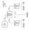
- FIG. 1is a system diagram illustrating communication system 100 .
- Communication system 100includes wireless access nodes 111 - 112 , wireless communication devices 121 - 122 , wireless access control system 130 , and core network 140 .
- Wireless access node 111 and wireless communication devices 121communicate over wireless link 161 .
- Wireless access node 112 and wireless communication devices 122communicate over wireless link 162 .
- Wireless access control system 130 and wireless access nodes 111 - 112communicate over links 151 - 152 , respectively.
- Wireless access control system 130 and core network 140communicate over link 153 .
- wireless communication devices 121receive wireless access for communication services from wireless access node 111
- wireless communication devices 122receive wireless access for communication services from wireless access node 112
- the communication servicescould include services provided by core network 140 or other systems, such as voice calls, data exchange, Internet access, text messaging, among other services.
- Each of wireless access nodes 111 - 112wirelessly exchange user and overhead communications with the associated wireless communication devices, as well as communicate with wireless access control system 130 or other systems.
- wireless links 161 - 162are merely representative of communication with a plurality of wireless communication devices over wireless links, and a different configuration, such as individual wireless links, could also be shown in FIG. 1 .
- FIG. 2is a flow diagram illustrating a method of operation of a wireless access control system, such as wireless access control system 130 of FIG. 1 .
- the operations of FIG. 2are referenced herein parenthetically.
- Wireless access node 111initially broadcasts a paging zone identifier for paging zone 1 for receipt by wireless communication devices 121 .
- Wireless access node 112initially broadcasts a paging zone identifier for paging zone 2 for receipt by wireless communication devices 122 .
- a paging zone identifieris a number, designator, or other representation which indicates a paging zone into which a wireless access node is grouped.
- Wireless access nodescan be grouped into different zones for delivery of paging information.
- This groupingcan be done to allow a page control system to route a subset of all paging information to different zones, thus reducing the amount of total paging traffic across a wireless communication network.
- many wireless access nodesare included in a paging zone.
- the paging zonescould be determined by a quantity of wireless access nodes per zone, geography, wireless coverage area limitations, or other factors, including combinations thereof.
- “zone 1 ”initially includes wireless access node 111 while “zone 2 ” initially includes wireless access node 112 . It should be understood that a different configuration or number of wireless access nodes in each zone could be employed.
- paging informationis transferred to wireless communication devices in communication system 100 .
- This paging informationcan indicate incoming calls, messages, network alerts, voice call alerts, text messages, audio messages, or other information, including combinations thereof.
- This paging informationis typically routed by a page control system through wireless access nodes for delivery to the wireless communication devices communicating therewith.
- a page control systemcould receive pages from core network 140 , could be generated from within a page control system, or could be generated due to activity of other wireless communication devices or wireless access nodes within communication system 100 .
- Wireless access control system 130could include a page control system.
- wireless access control system 130monitors ( 201 ) wireless access node 111 to determine when wireless access node 111 experiences wireless access congestion.
- the wireless access congestioncould be based upon a utilization level of the wireless access resources of wireless access node 111 , such as when access channel utilization exceeds a utilization threshold, when a predetermined amount of wireless communication devices are within a coverage area of wireless access node 111 , a level of communication traffic handled by wireless access node 111 , a number of wireless communication devices seeking to register for wireless access through wireless access node 111 , a number of wireless communication devices presently registered for communication service through wireless access node 111 , an amount of available data, voice call, or overhead communications capacity of wireless access node 111 , among other metrics of wireless access congestion.
- the wireless access congestioncould include determining if a time of day, a calendar event, or other time-based indicator indicates a predetermined time or event, which may indicate a present congestion event.
- the wireless access congestioncould include processing past monitoring of wireless congestion or future predictions to determine present wireless congestion.
- wireless access control system 130instructs ( 203 ) wireless access node 112 which broadcasts a paging zone identifier for paging zone 2 to toggle between broadcasting the paging zone identifier for paging zone 1 and broadcasting the paging zone identifier for paging zone 2 at a duty cycle.
- the duty cycleis a transition at a periodic cycle between broadcasting the paging zone identifier for paging zone 1 and broadcasting the paging zone identifier for paging zone 2 .
- the duty cyclecould be based upon a predetermined duty cycle, such as a 50% duty cycle, among other predetermined values, or could be based upon other factors.
- wireless access node 111 and wireless access node 112are located along a roadway carrying vehicle traffic, and where the duty cycle corresponds to an average speed of the vehicle traffic along the roadway or where the duty cycle corresponds to a volume level of the vehicle traffic along the roadway.
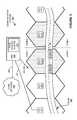
- FIG. 3is a system diagram illustrating communication system 300 .
- Communication system 300includes base transceiver stations (BTS) 311 - 315 , wireless communication devices 320 , mobile switching center (MSC) 330 , and core network 340 .
- BTSbase transceiver stations
- MSCmobile switching center
- core network 340a network 340 .
- MSC 330 and base transceiver stations 311 - 315communicate over backhaul links 351 - 355 , respectively.
- backhaul links 351 - 355are T1 links.
- MSC 330 and core network 340communicate over link 356 .
- link 356is a metropolitan area network (MAN) optical communication link.
- MANmetropolitan area network
- base transceiver stations 311 - 315are positioned along road 360 .
- Wireless communication devices 320such as mobile phones, are located in vehicles traveling to the right along road 360 , although different configurations could be employed.
- base transceiver stations 311 - 315each have a limited geographic range over which they can provide communication services to wireless communication devices.
- the limited range over which each base transceiver stations 311 - 315 can support communications with wireless communication devicesis indicated by hexagonal-shaped coverage areas in FIG. 3 . Although a hexagonal region defining each coverage area is shown in FIG.
- each hexagonal coverage area of base transceiver stations 311 - 315could be further divided into sectors, where a sector can represent a particular region of wireless coverage, typically served by a single antenna, antenna array, or base transceiver station of a wireless access node. Further base transceiver station equipment could be included in base transceiver stations 311 - 315 in examples where sectors are employed. In many examples, there are multiple sectors associated with a single wireless access node, antenna tower, or base station, with each sector describing a slice of the surrounding geographic region serviced by a base transceiver station.
- FIG. 4is a flow diagram illustrating a method of operation of communication system 300 .
- the operations of FIG. 4are referenced herein parenthetically.
- wireless communication devices 320each receive ( 401 ) wireless access to communication services from an associated base transceiver station as they each travel along road 360 .
- Wireless links between wireless communication devices 320 and each associated base transceiver stationare not shown in FIG. 3 for clarity.
- Wireless communication devices 320 registering in a coverage area of BTS 313receive ( 402 ) a first paging zone identifier as broadcast by BTS 313 . Some of wireless communication devices 320 may be registered for wireless access through others of BTS 311 - 315 before entering the wireless coverage area of BTS 313 , and a handoff may occur from the previous BTS to BTS 313 . As a part of the registration with BTS 313 , wireless communication devices receive the first paging zone identifier as broadcast by BTS 313 . In this example, each of BTS 311 - 315 receives a paging zone assignment from page control system 331 in MSC 330 over backhaul links 351 - 355 , respectively. Each wireless communication device registered for communication service with BTS 313 then reports the paging zone identifier that is broadcast by BTS 313 to paging control system 331 .
- BTS 313wirelessly exchanges ( 403 ) user and overhead communications with the associated registered wireless communication devices.
- the user communicationscould include voice calls, user data, Internet access, email, or other user communications.
- the overhead communicationscould include access or system parameter messages, resource assignments, paging information, text messages, or other overhead communications.
- Paging information, such as pages,are received or generated by page control system 331 of MSC 330 . These pages are then routed for delivery to the appropriate wireless communication devices.
- Page control system 331includes a listing of the paging zone identifiers that each of wireless communication devices 320 , as registered for communication service with any of BTS 311 - 315 , has reported to page control system 331 , as in operation 402 .
- pagesare only routed for delivery to the paging zone in which the recipient wireless communication devices are presently located. For example, pages intended for wireless communication devices registered in paging zone 1 are only transferred for delivery to wireless communication devices reporting paging zone 1 .
- BTS 313then experiences ( 404 ) wireless access congestion.
- BTS 313is located along a paging zone boundary.
- a paging zone boundarytypically comprises a boundary between a first paging zone associated with a first paging zone identifier and a second paging zone associated with a second paging zone identifier.
- a direction of travel of the wireless communication devices 320 receiving wireless access from BTS 313indicates travel across the paging zone boundary, as shown by the right arrow for wireless communication devices 320 .
- the wireless access congestion in this exampleoccurs when a utilization level of the wireless access resources of BTS 313 increases past a predetermined threshold. As shown in FIG.
- wireless communication devices 320have traveled into the coverage area of BTS 313 , perhaps due to rush hour vehicle traffic conditions, and have increased the utilization level of the wireless access resources of BTS 313 .
- the wireless access resourcescould include access channel availability or utilization, where the access channels are provided over a frequency, timeslot, or modulation in a wireless link for wireless communication devices to exchange communications through BTS 313 .
- the wireless access congestioncould also be based upon other factors, such as when a predetermined amount of wireless communication devices are within a coverage area of BTS 313 , a level of communication traffic handled by BTS 313 , a number of wireless communication devices seeking to register for wireless access through BTS 313 , a number of wireless communication devices presently registered for communication service through BTS 313 , an amount of available data, voice call, or overhead communications capacity of BTS 313 , among other metrics of wireless access congestion.
- the wireless access congestioncould include determining if a time of day, a calendar event, or other time-based indicator indicates a predetermined time or event, which may indicate a present congestion event, such as during rush hour events or sporting events.
- the wireless access congestioncould include processing past monitoring of wireless congestion or future predictions to determine present wireless congestion.
- page control system 331instructs ( 405 ) a second BTS, located across the paging zone boundary, to transition between broadcasting the first paging zone identifier and a second paging zone identifier at a periodic cycle.
- “zone 1 ” and “zone 2 ”form a paging zone boundary, indicated by the vertical dotted line.
- BTS 313is adjacent to the paging zone boundary and adjacent to BTS 314 across the paging zone boundary.
- BTS 313broadcasts a first paging zone identifier for “zone 1 ” and BTS 314 broadcasts a second paging zone identifier for “zone 2 .”
- a direction of travel of the wireless communication devices 320 receiving wireless access from BTS 313indicates travel across the paging zone boundary, as shown by the right arrow associated with wireless communication devices 320 .
- Page control system 331can anticipate possible congestion at BTS 314 , and instruct BTS 314 to help reduce the possible congestion.
- the periodic cycleis a repeated transition between broadcasting the paging zone identifier for paging zone 1 and broadcasting the paging zone identifier for paging zone 2 , such as at a duty cycle.
- only one paging zone identifieris broadcast at any particular time, although in other examples, both the first and second paging zone identifiers could be broadcast concurrently for a period of time by BTS 314 .
- BTS 313could also be instructed by page control system 331 to transition between broadcasting the first paging zone identifier and a second paging zone identifier at a periodic cycle.
- the periodic cyclescould be varied for each BTS.
- the transitionscould be scheduled for different paging zone identifiers at adjacent base transceiver stations so a BTS does not broadcast the same paging zone identifier as an adjacent BTS during a periodic cycle.
- Overlapping time periodscould also be employed.
- the periodic cyclescould be based upon a predetermined duty cycle, such as a 50% duty cycle, among other predetermined values, or could be based upon other factors.
- Other factorscould include examples where a duty cycle or transition rate corresponds to an average speed of the vehicle traffic along the roadway or a volume level of the vehicle traffic along the roadway.
- a higher average speed of the vehicle trafficcould correspond to broadcasting the second paging zone identifier at BTS 314 for a shorter period of time.
- a high volume level of vehicle trafficcould correspond to a longer broadcast period for the first paging zone identifier at BTS 314 .
- Different time periods and associations with vehicle speeds or volumescould be employed.
- Wireless communication devicesreceive ( 406 ) the associated paging zone identifier when registering for wireless access from BTS 314 .
- wireless communication devicesreceive the associated paging zone identifier as broadcast by BTS 314 .
- BTS 314transitions between broadcasting the first paging zone identifier and the second paging zone identifier at a periodic cycle, as individual wireless communication devices register for wireless access with BTS 314 , a varying paging zone identifier is received by the individual wireless communication devices.
- the same paging zone identifier as initially received from BTS 313will be received by a wireless communication device registering for subsequent wireless access from BTS 314 , while in other instances a different paging zone identifier than initially received from BTS 313 will be received from BTS 314 .
- Wireless communication devices registering for communication service with BTS 314then only report a paging zone assignment to paging control system 331 if a change in paging zone identifier is received. Since only a portion of wireless communication devices 320 enter the coverage area of BTS 314 at any given time, due to the motion of the associated vehicle traffic along road 360 , communication traffic at BTS 314 is reduced as paging zone assignment reporting, among other communication traffic, is reduced.
- Wireless communication devices 320receive ( 407 ) paging information according to the assigned paging zone.
- paging informationsuch as pages
- page control system 331 of MSC 330for delivery to specific wireless communication devices.
- These pagesare then routed for delivery to the appropriate wireless communication devices.
- page control system 331includes a listing of the paging zone identifiers that each of wireless communication devices 320 has reported to page control system 331 .
- pagesare only routed for delivery through wireless access nodes in the paging zone in which the recipient wireless communication devices are presently located. For example, pages intended for wireless communication devices registered in paging zone 1 are only transferred for delivery to wireless access nodes where wireless communication devices have reported paging zone 1 .
- FIG. 5is a block diagram illustrating wireless access control system 500 , as an example of wireless access control system 130 found in FIG. 1 , or MSC 330 found in FIG. 3 , although wireless access control system 130 or MSC 330 could use other configurations.
- Wireless access control system 500includes control interface 510 , processing system 520 , and network interface 530 .
- Control interface 510 , processing system 520 , and network interface 530communicate over bus 540 .
- Wireless access control system 500may be distributed among multiple devices that together form elements 510 , 520 - 522 , 530 , 540 , and 550 - 551 .
- Control interface 510comprises communication interfaces for communicating with and controlling the operations of wireless access nodes, such as base stations, over links 550 .
- Control interface 510also receives command and control information from processing system 520 or network interface 530 for controlling the operations of wireless access nodes over links 550 , instructing wireless access nodes on which paging zone identifiers to broadcast and duty cycles of the paging zone identifiers, among other operations.
- Links 550could each use various protocols or communication formats as described herein for links 151 - 152 or links 351 - 355 , including combinations, variations, or improvements thereof.
- Processing system 520includes storage system 521 .
- Processing system 520retrieves and executes software 522 from storage system 521 .
- processing system 520is located within the same equipment in which control interface 510 or network interface 530 are located.
- processing system 520comprises specialized circuitry, and software 522 or storage system 521 could be included in the specialized circuitry to operate processing system 520 as described herein.
- Storage system 521could include a computer-readable medium such as a disk, tape, integrated circuit, server, or some other memory device, and also may be distributed among multiple memory devices.
- Software 522may include an operating system, logs, utilities, drivers, networking software, and other software typically loaded onto a computer system.
- Software 522could contain an application program, firmware, or some other form of computer-readable processing instructions. When executed by processing system 520 , software 522 directs processing system 520 to operate as described herein, such as determining paging zone identifiers for wireless access nodes to broadcast, and determining duty cycles of the paging zone identifier broadcasts, among other operations.
- Network interface 530comprises network router and gateway equipment for communicating with a core network of a wireless communication provider, such as with core network 140 or core network 340 .
- Network interface 530exchanges user communications and overhead communications with a core network of a wireless communication system over link 551 .
- Link 551could use various protocols or communication formats as described herein for link 153 or 356 , including combinations, variations, or improvements thereof.
- Bus 540comprises a physical, logical, or virtual communication link, capable of communicating data, control signals, power, and communications, along with other information.
- bus 540is encapsulated within the elements of control interface 510 , processing system 520 , or network interface 530 , and may be a software or logical link.
- bus 540uses various communication media, such as air, space, metal, optical fiber, or some other signal propagation path, including combinations thereof.
- Bus 540could be a direct link or might include various equipment, intermediate components, systems, and networks.
- wireless communication devices 121 - 122each comprise radio frequency (RF) communication circuitry and antenna elements.
- the RF communication circuitrytypically includes amplifiers, filters, modulators, and signal processing circuitry.
- wireless communication devices 121 - 122each include circuitry and equipment to exchange communications of wireless communication services over wireless links with wireless access systems, request communication services, and receive control information from wireless access nodes, among other operations.
- Wireless communication devices 121 - 122may also each include user interface systems, memory devices, computer-readable storage mediums, software, processing circuitry, or other communication components.
- Each of wireless communication devices 121 - 122may be a user device, subscriber equipment, customer equipment, access terminal, telephone, mobile wireless telephone, computer, e-book, mobile Internet appliance, wireless network interface card, media player, game console, or some other wireless communication apparatus, including combinations thereof. Although a number of representative wireless communication devices are shown in FIG. 1 , it should be understood that a different number of wireless communication devices could be shown.
- Wireless access nodes 111 - 112each comprise RF communication and control circuitry, antenna elements, and communication routing equipment and systems.
- the RF communication circuitrytypically includes amplifiers, filters, RF modulators, transceivers, and signal processing circuitry.
- wireless access nodes 111 - 112each include equipment to provide wireless access to communication services within a coverage area to user devices such as wireless communication devices 121 - 122 shown in FIG. 1 , route user communications between core network 140 and wireless communication devices, broadcast paging zone identifiers, transfer paging information, provide network information, handoff information, or configuration information to wireless communication devices, among other operations.
- Wireless access nodes 111 - 112may also each comprise data modems, routers, servers, memory devices, software, processing systems, cabling, network communication interfaces, physical structural supports, or other communication apparatuses. Wireless access nodes 111 - 112 may also each comprise base stations, base transceiver stations (BTS), base station controllers (BSC), or other communication equipment and apparatuses.
- BTSbase transceiver stations
- BSCbase station controllers
- Wireless access control system 330includes network equipment capable of transferring pages for delivery to wireless communication devices through wireless access nodes, as well as processing systems to analyze congestion of wireless access nodes.
- Examples of wireless access control system 330include radio node controllers (RNC), mobile switching centers (MSC), call processing equipment, telephone switches, routers, gateways, computer processing equipment, microprocessors, as well as other type of communication and processing equipment, including combinations thereof.
- Core network 140could include further wireless access nodes, base station controllers (BSC), mobile switching centers (MSC), radio node controllers (RNC), call processing systems, authentication, authorization and accounting (AAA) equipment, access service network gateways (ASN-GW), Internet access nodes, telephony service nodes, wireless data access points, or other communication systems, including combinations thereof.
- Core network 140may also comprise optical networks, asynchronous transfer mode (ATM) networks, packet networks, metropolitan-area networks (MAN), Internet systems, or other network topologies, equipment, or systems, including combinations thereof.
- core network 140includes many wireless access systems and associated equipment for providing communication services to many user devices across a geographic region.
- Wireless links 161 - 162each use the air or space as the transport media.
- Wireless links 161 - 162may each use various protocols, such as Code Division Multiple Access (CDMA), Evolution-Data Optimized (EV-DO), single-carrier radio transmission technology link (1 ⁇ RTT), Worldwide Interoperability for Microwave Access (WIMAX), Global System for Mobile Communication (GSM), Universal Mobile Telecommunications System (UMTS), Long Term Evolution (LTE), Wireless Fidelity (WiFi), High Speed Packet Access (HSPA), Radio Link Protocol (RLP), or some other wireless communication format, including combinations, improvements, or variations thereof.
- CDMACode Division Multiple Access
- EV-DOEvolution-Data Optimized
- 1 ⁇ RTTsingle-carrier radio transmission technology link
- WiXWorldwide Interoperability for Microwave Access
- GSMGlobal System for Mobile Communication
- UMTSUniversal Mobile Telecommunications System
- LTELong Term Evolution
- WiFiWireless Fidelity
- HSPAHigh Speed Packet Access
- RLPRadio Link Protocol
- Communication links 151 - 153each use metal, glass, optical, air, space, or some other material as the transport media.
- Communication links 151 - 153could each use various communication protocols, such as Time Division Multiplex (TDM), asynchronous transfer mode (ATM), Internet Protocol (IP), Ethernet, synchronous optical networking (SONET), circuit-switched, communication signaling, or some other communication format, including combinations, improvements, or variations thereof.
- Communication links 151 - 153could each be a direct link or may include intermediate networks, systems, or devices.
- Links 151 - 153 and 161 - 162may each include many different signals sharing the same link—as represented by the associated lines in FIG. 1 —comprising access channels, paging channels, notification channels, forward links, reverse links, user communications, communication sessions, overhead communications, frequencies, other channels, carriers, timeslots, spreading codes, transportation ports, logical transportation links, network sockets, packets, or communication directions.
Landscapes
- Engineering & Computer Science (AREA)
- Computer Networks & Wireless Communication (AREA)
- Signal Processing (AREA)
- Mobile Radio Communication Systems (AREA)
Abstract
Description
Claims (20)
Priority Applications (1)
| Application Number | Priority Date | Filing Date | Title |
|---|---|---|---|
| US12/854,666US8116761B1 (en) | 2010-08-11 | 2010-08-11 | Modifying wireless network paging zone broadcast based on wireless access congestion |
Applications Claiming Priority (1)
| Application Number | Priority Date | Filing Date | Title |
|---|---|---|---|
| US12/854,666US8116761B1 (en) | 2010-08-11 | 2010-08-11 | Modifying wireless network paging zone broadcast based on wireless access congestion |
Publications (1)
| Publication Number | Publication Date |
|---|---|
| US8116761B1true US8116761B1 (en) | 2012-02-14 |
Family
ID=45561540
Family Applications (1)
| Application Number | Title | Priority Date | Filing Date |
|---|---|---|---|
| US12/854,666Active2030-08-13US8116761B1 (en) | 2010-08-11 | 2010-08-11 | Modifying wireless network paging zone broadcast based on wireless access congestion |
Country Status (1)
| Country | Link |
|---|---|
| US (1) | US8116761B1 (en) |
Cited By (3)
| Publication number | Priority date | Publication date | Assignee | Title |
|---|---|---|---|---|
| US8503308B1 (en)* | 2010-10-29 | 2013-08-06 | Sprint Communications Company L.P. | Page routing system |
| US10104575B1 (en)* | 2016-02-09 | 2018-10-16 | CSC Holdings, LLC | Dynamic communication channel switching in a wireless access point |
| US20250008442A1 (en)* | 2023-06-27 | 2025-01-02 | T-Mobile Innovations Llc | System and method for power management via network transmission |
Citations (28)
| Publication number | Priority date | Publication date | Assignee | Title |
|---|---|---|---|---|
| US5117502A (en) | 1990-03-19 | 1992-05-26 | Fujitsu Limited | Mobile radio communication system |
| US5327575A (en) | 1992-03-23 | 1994-07-05 | Motorola, Inc. | Directional handover control in digital mobile radio systems employing MAHO |
| US5379447A (en) | 1991-12-11 | 1995-01-03 | Motorola, Inc. | Method of selecting a handoff target in a cellular communication system |
| US5379446A (en) | 1990-05-30 | 1995-01-03 | British Telecommunications Public Limited Company | Cellular radio with microcellular/macrocellular handoff |
| US5483668A (en) | 1992-06-24 | 1996-01-09 | Nokia Mobile Phones Ltd. | Method and apparatus providing handoff of a mobile station between base stations using parallel communication links established with different time slots |
| US5513246A (en) | 1990-12-07 | 1996-04-30 | Telefonaktiebolaget Lm Ericsson | Radiotelephone locating and handoff using alternative criteria |
| US5621784A (en) | 1991-09-20 | 1997-04-15 | Qualcomm Incorporated | Comprehensive mobile communications device registration method |
| US5732352A (en) | 1995-09-29 | 1998-03-24 | Motorola, Inc. | Method and apparatus for performing handoff in a wireless communication system |
| US5822454A (en) | 1995-04-10 | 1998-10-13 | Rebus Technology, Inc. | System and method for automatic page registration and automatic zone detection during forms processing |
| US5915219A (en) | 1992-09-10 | 1999-06-22 | Nokia Telecommunications Oy | Cellular radio network divided into a primary network covering a selected operating area and at least one subsystem covering possibly overlapping area, with possibility of handoff and registration between primary network and subsystem |
| US5953661A (en) | 1997-05-16 | 1999-09-14 | Nextel Communications | Method of maximizing spectral efficiency in a cellular communications system |
| US5991626A (en) | 1992-06-18 | 1999-11-23 | Telefonakitiebolaget Lm Ericsson | Methods and apparatus pertaining to handoff in a mobile telecommunication system |
| US5995836A (en) | 1997-12-24 | 1999-11-30 | Telefonaktiebolaget Lm Ericsson | Method and system for variable handoff hysteresis in a radiocommunication system |
| US6295452B1 (en) | 1998-11-11 | 2001-09-25 | Lg Information & Communications, Ltd. | Mobile communication system that supports soft handoff between switching stations and method for implementing handoff |
| US6381458B1 (en) | 1998-05-15 | 2002-04-30 | Telefonaktiebolaget Lm Ericsson (Publ) | Method and system for soft handoff control based on access network capacity |
| US6507740B2 (en) | 1999-05-18 | 2003-01-14 | Ericsson Inc. | Adaptive threshold of handoff in mobile telecommunication systems |
| US6539227B1 (en) | 1998-12-18 | 2003-03-25 | Telefonaktiebolaget Lm Ericsson (Publ) | Methods and systems for controlling hard and soft handoffs in radio communications systems |
| US6631263B1 (en) | 1998-11-06 | 2003-10-07 | Telefonaktiebolaget Lm Ericsson (Publ) | Cell hand-off border identification using MS positioning and signal strength values |
| US20030216140A1 (en)* | 2002-05-17 | 2003-11-20 | Georg Chambert | Universal identification system for access points of wireless access networks |
| US6745034B2 (en) | 2000-12-22 | 2004-06-01 | Nokia Corporation | Apparatus, and associated method, for adaptively selecting a handoff threshold in a radio communication system |
| US6771962B2 (en) | 2001-03-30 | 2004-08-03 | Nokia Corporation | Apparatus, and an associated method, by which to provide temporary identifiers to a mobile node involved in a communication handover |
| US6778830B1 (en) | 1999-10-26 | 2004-08-17 | Nec Corporation | Mobile telecommunication system and channel handoff system between the mobile telecommunication systems |
| US20060240827A1 (en) | 2005-04-21 | 2006-10-26 | Kyocera Wireless Corp. | Apparatus and method for performing handoff with a mobile station having a smart antenna |
| US20070099618A1 (en) | 2005-10-31 | 2007-05-03 | Samsung Electronics Co., Ltd. | Method and apparatus for preventing excessive handovers in mobile communication system |
| US7263358B2 (en) | 2004-07-02 | 2007-08-28 | Groundhog Technologies Inc. | Method for detecting and reducing ping-pong handover effect of cellular network |
| US20080014943A1 (en) | 2006-07-13 | 2008-01-17 | Samsung Electronics Co., Ltd. | Method and apparatus for handoff decision in mobile communication system |
| US20080091308A1 (en)* | 2006-07-27 | 2008-04-17 | Jeremy Henson | Devices, Systems, and Methods for Adaptive RF Sensing in Arc Fault Detection |
| US20100002582A1 (en)* | 2008-07-03 | 2010-01-07 | Achim Luft | Apparatus and methods for managing access and update requests in a wireless network |
- 2010
- 2010-08-11USUS12/854,666patent/US8116761B1/enactiveActive
Patent Citations (29)
| Publication number | Priority date | Publication date | Assignee | Title |
|---|---|---|---|---|
| US5117502A (en) | 1990-03-19 | 1992-05-26 | Fujitsu Limited | Mobile radio communication system |
| US5379446A (en) | 1990-05-30 | 1995-01-03 | British Telecommunications Public Limited Company | Cellular radio with microcellular/macrocellular handoff |
| US5513246A (en) | 1990-12-07 | 1996-04-30 | Telefonaktiebolaget Lm Ericsson | Radiotelephone locating and handoff using alternative criteria |
| US5621784A (en) | 1991-09-20 | 1997-04-15 | Qualcomm Incorporated | Comprehensive mobile communications device registration method |
| US5379447A (en) | 1991-12-11 | 1995-01-03 | Motorola, Inc. | Method of selecting a handoff target in a cellular communication system |
| US5327575A (en) | 1992-03-23 | 1994-07-05 | Motorola, Inc. | Directional handover control in digital mobile radio systems employing MAHO |
| US5991626A (en) | 1992-06-18 | 1999-11-23 | Telefonakitiebolaget Lm Ericsson | Methods and apparatus pertaining to handoff in a mobile telecommunication system |
| US5483668A (en) | 1992-06-24 | 1996-01-09 | Nokia Mobile Phones Ltd. | Method and apparatus providing handoff of a mobile station between base stations using parallel communication links established with different time slots |
| US5915219A (en) | 1992-09-10 | 1999-06-22 | Nokia Telecommunications Oy | Cellular radio network divided into a primary network covering a selected operating area and at least one subsystem covering possibly overlapping area, with possibility of handoff and registration between primary network and subsystem |
| US5822454A (en) | 1995-04-10 | 1998-10-13 | Rebus Technology, Inc. | System and method for automatic page registration and automatic zone detection during forms processing |
| US5732352A (en) | 1995-09-29 | 1998-03-24 | Motorola, Inc. | Method and apparatus for performing handoff in a wireless communication system |
| US5953661A (en) | 1997-05-16 | 1999-09-14 | Nextel Communications | Method of maximizing spectral efficiency in a cellular communications system |
| US5995836A (en) | 1997-12-24 | 1999-11-30 | Telefonaktiebolaget Lm Ericsson | Method and system for variable handoff hysteresis in a radiocommunication system |
| US6381458B1 (en) | 1998-05-15 | 2002-04-30 | Telefonaktiebolaget Lm Ericsson (Publ) | Method and system for soft handoff control based on access network capacity |
| US6631263B1 (en) | 1998-11-06 | 2003-10-07 | Telefonaktiebolaget Lm Ericsson (Publ) | Cell hand-off border identification using MS positioning and signal strength values |
| US6295452B1 (en) | 1998-11-11 | 2001-09-25 | Lg Information & Communications, Ltd. | Mobile communication system that supports soft handoff between switching stations and method for implementing handoff |
| US6754493B1 (en) | 1998-12-18 | 2004-06-22 | Telefonaktiebolaget Lm Ericsson | Method and systems for dynamic threshold adjustment for handoffs in radio communication systems |
| US6539227B1 (en) | 1998-12-18 | 2003-03-25 | Telefonaktiebolaget Lm Ericsson (Publ) | Methods and systems for controlling hard and soft handoffs in radio communications systems |
| US6507740B2 (en) | 1999-05-18 | 2003-01-14 | Ericsson Inc. | Adaptive threshold of handoff in mobile telecommunication systems |
| US6778830B1 (en) | 1999-10-26 | 2004-08-17 | Nec Corporation | Mobile telecommunication system and channel handoff system between the mobile telecommunication systems |
| US6745034B2 (en) | 2000-12-22 | 2004-06-01 | Nokia Corporation | Apparatus, and associated method, for adaptively selecting a handoff threshold in a radio communication system |
| US6771962B2 (en) | 2001-03-30 | 2004-08-03 | Nokia Corporation | Apparatus, and an associated method, by which to provide temporary identifiers to a mobile node involved in a communication handover |
| US20030216140A1 (en)* | 2002-05-17 | 2003-11-20 | Georg Chambert | Universal identification system for access points of wireless access networks |
| US7263358B2 (en) | 2004-07-02 | 2007-08-28 | Groundhog Technologies Inc. | Method for detecting and reducing ping-pong handover effect of cellular network |
| US20060240827A1 (en) | 2005-04-21 | 2006-10-26 | Kyocera Wireless Corp. | Apparatus and method for performing handoff with a mobile station having a smart antenna |
| US20070099618A1 (en) | 2005-10-31 | 2007-05-03 | Samsung Electronics Co., Ltd. | Method and apparatus for preventing excessive handovers in mobile communication system |
| US20080014943A1 (en) | 2006-07-13 | 2008-01-17 | Samsung Electronics Co., Ltd. | Method and apparatus for handoff decision in mobile communication system |
| US20080091308A1 (en)* | 2006-07-27 | 2008-04-17 | Jeremy Henson | Devices, Systems, and Methods for Adaptive RF Sensing in Arc Fault Detection |
| US20100002582A1 (en)* | 2008-07-03 | 2010-01-07 | Achim Luft | Apparatus and methods for managing access and update requests in a wireless network |
Cited By (7)
| Publication number | Priority date | Publication date | Assignee | Title |
|---|---|---|---|---|
| US8503308B1 (en)* | 2010-10-29 | 2013-08-06 | Sprint Communications Company L.P. | Page routing system |
| US10104575B1 (en)* | 2016-02-09 | 2018-10-16 | CSC Holdings, LLC | Dynamic communication channel switching in a wireless access point |
| US10536877B1 (en)* | 2016-02-09 | 2020-01-14 | CSC Holdings, LLC | Dynamic communication channel switching in a wireless access point |
| US10959127B1 (en)* | 2016-02-09 | 2021-03-23 | CSC Holdings, LLC | Dynamic communication channel switching in a wireless access point |
| US11622295B1 (en)* | 2016-02-09 | 2023-04-04 | CSC Holdings, LLC | Dynamic communication channel switching in a wireless access point |
| US12022321B1 (en)* | 2016-02-09 | 2024-06-25 | CSC Holdings, LLC | Dynamic communication channel switching in a wireless access point |
| US20250008442A1 (en)* | 2023-06-27 | 2025-01-02 | T-Mobile Innovations Llc | System and method for power management via network transmission |
Similar Documents
| Publication | Publication Date | Title |
|---|---|---|
| US8358577B1 (en) | Using wireless links to offload backhaul communications | |
| US9572197B1 (en) | Configuration of remote radio head antenna ports | |
| US9986483B1 (en) | Handoff target selection based on media type | |
| US8116761B1 (en) | Modifying wireless network paging zone broadcast based on wireless access congestion | |
| US8477693B1 (en) | Out-of sector message stream delivery | |
| US9344857B1 (en) | Frequency band allocation in a wireless communication network | |
| US9560668B1 (en) | Systems and methods for scheduling low-delay transmissions in a communication network | |
| US20080101302A1 (en) | Method and system for managing communication sessions in a plurality of wireless communication networks | |
| US8874157B1 (en) | Scheduling wireless communication power resources in wireless communication systems | |
| US8442012B1 (en) | Selecting wireless access resources based on past wireless activity | |
| US8605652B1 (en) | Wireless tune away based upon congestion | |
| US9001769B1 (en) | Managing access node channel loading | |
| US8265662B1 (en) | Data mode paging in wireless communication networks | |
| US8503308B1 (en) | Page routing system | |
| US9674861B1 (en) | Systems and methods for scheduling transmissions from an access node in a communication network | |
| US8626204B1 (en) | Delivery of paging information to sets of wireless communication devices | |
| US9877204B1 (en) | Systems and methods for a multi-layer tracking area code assignment | |
| US9763130B1 (en) | Systems and methods for managing congestion in a wireless communication network | |
| US8737987B1 (en) | Enhanced wireless device network rescan rate determination | |
| US8576880B1 (en) | Congestion-based wireless paging channels | |
| US8279799B1 (en) | Intelligent transmission of wireless communication overhead messages | |
| US8223711B1 (en) | Efficient message delivery to wireless communication devices | |
| US9363716B1 (en) | Coverage area adjustment for circuit switched fallback | |
| US9525535B1 (en) | Systems and methods for scheduling transmissions from an access node | |
| US8243656B1 (en) | Efficient access identifier utilization in wireless access systems |
Legal Events
| Date | Code | Title | Description |
|---|---|---|---|
| AS | Assignment | Owner name:SPRINT COMMUNICATIONS COMPANY L.P., KANSAS Free format text:ASSIGNMENT OF ASSIGNORS INTEREST;ASSIGNORS:SINGH, JASINDER PAL;VARGANTWAR, SACHIN R.;SHETTY, MANOJ;AND OTHERS;SIGNING DATES FROM 20100806 TO 20100810;REEL/FRAME:024825/0320 | |
| STCF | Information on status: patent grant | Free format text:PATENTED CASE | |
| FPAY | Fee payment | Year of fee payment:4 | |
| AS | Assignment | Owner name:DEUTSCHE BANK TRUST COMPANY AMERICAS, NEW YORK Free format text:GRANT OF FIRST PRIORITY AND JUNIOR PRIORITY SECURITY INTEREST IN PATENT RIGHTS;ASSIGNOR:SPRINT COMMUNICATIONS COMPANY L.P.;REEL/FRAME:041895/0210 Effective date:20170203 | |
| MAFP | Maintenance fee payment | Free format text:PAYMENT OF MAINTENANCE FEE, 8TH YEAR, LARGE ENTITY (ORIGINAL EVENT CODE: M1552); ENTITY STATUS OF PATENT OWNER: LARGE ENTITY Year of fee payment:8 | |
| AS | Assignment | Owner name:SPRINT COMMUNICATIONS COMPANY L.P., KANSAS Free format text:TERMINATION AND RELEASE OF FIRST PRIORITY AND JUNIOR PRIORITY SECURITY INTEREST IN PATENT RIGHTS;ASSIGNOR:DEUTSCHE BANK TRUST COMPANY AMERICAS;REEL/FRAME:052969/0475 Effective date:20200401 Owner name:DEUTSCHE BANK TRUST COMPANY AMERICAS, NEW YORK Free format text:SECURITY AGREEMENT;ASSIGNORS:T-MOBILE USA, INC.;ISBV LLC;T-MOBILE CENTRAL LLC;AND OTHERS;REEL/FRAME:053182/0001 Effective date:20200401 | |
| AS | Assignment | Owner name:T-MOBILE INNOVATIONS LLC, KANSAS Free format text:ASSIGNMENT OF ASSIGNORS INTEREST;ASSIGNOR:SPRINT COMMUNICATIONS COMPANY L.P.;REEL/FRAME:055604/0001 Effective date:20210303 | |
| AS | Assignment | Owner name:SPRINT SPECTRUM LLC, KANSAS Free format text:RELEASE BY SECURED PARTY;ASSIGNOR:DEUTSCHE BANK TRUST COMPANY AMERICAS;REEL/FRAME:062595/0001 Effective date:20220822 Owner name:SPRINT INTERNATIONAL INCORPORATED, KANSAS Free format text:RELEASE BY SECURED PARTY;ASSIGNOR:DEUTSCHE BANK TRUST COMPANY AMERICAS;REEL/FRAME:062595/0001 Effective date:20220822 Owner name:SPRINT COMMUNICATIONS COMPANY L.P., KANSAS Free format text:RELEASE BY SECURED PARTY;ASSIGNOR:DEUTSCHE BANK TRUST COMPANY AMERICAS;REEL/FRAME:062595/0001 Effective date:20220822 Owner name:SPRINTCOM LLC, KANSAS Free format text:RELEASE BY SECURED PARTY;ASSIGNOR:DEUTSCHE BANK TRUST COMPANY AMERICAS;REEL/FRAME:062595/0001 Effective date:20220822 Owner name:CLEARWIRE IP HOLDINGS LLC, KANSAS Free format text:RELEASE BY SECURED PARTY;ASSIGNOR:DEUTSCHE BANK TRUST COMPANY AMERICAS;REEL/FRAME:062595/0001 Effective date:20220822 Owner name:CLEARWIRE COMMUNICATIONS LLC, KANSAS Free format text:RELEASE BY SECURED PARTY;ASSIGNOR:DEUTSCHE BANK TRUST COMPANY AMERICAS;REEL/FRAME:062595/0001 Effective date:20220822 Owner name:BOOST WORLDWIDE, LLC, KANSAS Free format text:RELEASE BY SECURED PARTY;ASSIGNOR:DEUTSCHE BANK TRUST COMPANY AMERICAS;REEL/FRAME:062595/0001 Effective date:20220822 Owner name:ASSURANCE WIRELESS USA, L.P., KANSAS Free format text:RELEASE BY SECURED PARTY;ASSIGNOR:DEUTSCHE BANK TRUST COMPANY AMERICAS;REEL/FRAME:062595/0001 Effective date:20220822 Owner name:T-MOBILE USA, INC., WASHINGTON Free format text:RELEASE BY SECURED PARTY;ASSIGNOR:DEUTSCHE BANK TRUST COMPANY AMERICAS;REEL/FRAME:062595/0001 Effective date:20220822 Owner name:T-MOBILE CENTRAL LLC, WASHINGTON Free format text:RELEASE BY SECURED PARTY;ASSIGNOR:DEUTSCHE BANK TRUST COMPANY AMERICAS;REEL/FRAME:062595/0001 Effective date:20220822 Owner name:PUSHSPRING, LLC, WASHINGTON Free format text:RELEASE BY SECURED PARTY;ASSIGNOR:DEUTSCHE BANK TRUST COMPANY AMERICAS;REEL/FRAME:062595/0001 Effective date:20220822 Owner name:LAYER3 TV, LLC, WASHINGTON Free format text:RELEASE BY SECURED PARTY;ASSIGNOR:DEUTSCHE BANK TRUST COMPANY AMERICAS;REEL/FRAME:062595/0001 Effective date:20220822 Owner name:IBSV LLC, WASHINGTON Free format text:RELEASE BY SECURED PARTY;ASSIGNOR:DEUTSCHE BANK TRUST COMPANY AMERICAS;REEL/FRAME:062595/0001 Effective date:20220822 | |
| MAFP | Maintenance fee payment | Free format text:PAYMENT OF MAINTENANCE FEE, 12TH YEAR, LARGE ENTITY (ORIGINAL EVENT CODE: M1553); ENTITY STATUS OF PATENT OWNER: LARGE ENTITY Year of fee payment:12 |